KR920009552B1 - Reinforcing bushings and tips for fiberglass molding - Google Patents
Reinforcing bushings and tips for fiberglass molding Download PDFInfo
- Publication number
- KR920009552B1 KR920009552B1 KR1019900007625A KR900007625A KR920009552B1 KR 920009552 B1 KR920009552 B1 KR 920009552B1 KR 1019900007625 A KR1019900007625 A KR 1019900007625A KR 900007625 A KR900007625 A KR 900007625A KR 920009552 B1 KR920009552 B1 KR 920009552B1
- Authority
- KR
- South Korea
- Prior art keywords
- tip
- bushing
- tips
- cross
- section
- Prior art date
- Legal status (The legal status is an assumption and is not a legal conclusion. Google has not performed a legal analysis and makes no representation as to the accuracy of the status listed.)
- Expired
Links
Images


Classifications
-
- C—CHEMISTRY; METALLURGY
- C03—GLASS; MINERAL OR SLAG WOOL
- C03B—MANUFACTURE, SHAPING, OR SUPPLEMENTARY PROCESSES
- C03B37/00—Manufacture or treatment of flakes, fibres, or filaments from softened glass, minerals, or slags
- C03B37/08—Bushings, e.g. construction, bushing reinforcement means; Spinnerettes; Nozzles; Nozzle plates
- C03B37/083—Nozzles; Bushing nozzle plates
Landscapes
- Engineering & Computer Science (AREA)
- Chemical & Material Sciences (AREA)
- Life Sciences & Earth Sciences (AREA)
- General Life Sciences & Earth Sciences (AREA)
- Geochemistry & Mineralogy (AREA)
- Manufacturing & Machinery (AREA)
- Materials Engineering (AREA)
- Organic Chemistry (AREA)
- Manufacture, Treatment Of Glass Fibers (AREA)
- Inorganic Fibers (AREA)
- Spinning Methods And Devices For Manufacturing Artificial Fibers (AREA)
Abstract
내용 없음.No content.
Description
제1도는 통상적인 유리섬유의 성형방법에 대한 개략도로서, 부싱, 도포기 및 권취기를 도시함.1 is a schematic view of a conventional method for forming glass fibers, showing a bushing, an applicator and a winder.
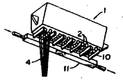
제2도는 부싱, 부싱에 결합된 냉각핀, 개개의 팁 및 팁으로부터 사출된 섬유의 사시도.2 is a perspective view of a bushing, cooling fins coupled to the bushing, individual tips and fibers ejected from the tip.
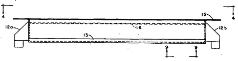
제3도는 전형적인 800팁형 제조부싱의 정면도.3 is a front view of a typical 800 tip manufacturing bushing.
제4도는 4-4선에서 본 제3도의 부싱에 대한 평면도.4 is a plan view of the bushing of FIG. 3 seen from lines 4-4.
제5도는 원형섬유를 제조하는데 사용될수 있는 각종 비원형 팁에 대한 사시도.5 is a perspective view of various non-circular tips that can be used to make circular fibers.
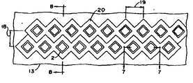
제6도는 가장 바람직한 위치에 배열된 정사각형 팁들을 갖는 팁 프레이트의 저면도.6 is a bottom view of the tip plate with square tips arranged in the most preferred position.
제7도는 제6도의 7-7선을 따라 절취한 인접 팁들의 단면도.FIG. 7 is a cross-sectional view of adjacent tips taken along line 7-7 of FIG. 6. FIG.
제8도는 제6도의 8-8선을 따라, 절취한 인접 팁들의 단면도.FIG. 8 is a cross-sectional view of the adjacent adjacent tips taken along line 8-8 of FIG.
제9도는 제6도에 도시된 팁 플레이트의 저부단면에 대한 확대 사시도.9 is an enlarged perspective view of the bottom cross section of the tip plate shown in FIG.
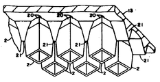
제10도는 일체형 리브로 보강된 정사각형 팁을 사용한 것을 제외하고는 제9도에 도시한 것과 동일한 팁 플레이트의 확대 사시도.FIG. 10 is an enlarged perspective view of the same tip plate as shown in FIG. 9 except that a square tip reinforced with integral ribs is used.
제11도는 가장 바람직한 위치에 배열된 리브보강재와 정사긱형 팁들을 나타내는 제10도에 도시한 팁 플레이트의 저면도.FIG. 11 is a bottom view of the tip plate shown in FIG. 10 showing rib reinforcements and square tips arranged in the most preferred position.
제12도는 제11도의 12-12선을 따라 절취한 인접 팁들의 단면도.FIG. 12 is a cross-sectional view of adjacent tips taken along line 12-12 of FIG.
제13도는 제11도의 13-13선을 따라 절취한 팁들의 단면도.13 is a cross-sectional view of the tips taken along line 13-13 of FIG.
제14도는 제11도의 14-14선을 따라 절취한 2개의 팁들에 대한 단면도.FIG. 14 is a cross sectional view of two tips taken along line 14-14 of FIG.
* 도면의 주요부분에 대한 부호의 설명* Explanation of symbols for the main parts of the drawings
1 : 부틸 어셈블리 2 : 팁1: Butyl Assembly 2: Tip
3 : 권취기 4 : 유리섬유3: winding machine 4: glass fiber
5 : 도포기 7 : 개더링 슈우5: applicator 7: gathering shoe
8 : 로테이팅 스파이어럴 9 : 카드보오드 형성튜브8: Rotating spiral 9: Card board forming tube
10 : 냉각핀 11 : 다기관10: cooling fin 11: manifold
12a, 12b : 단자 13 : 팁 플레이트12a, 12b: Terminal 13: Tip plate
15 : 플렌지 21 : 리브15: flange 21: rib
본 발명은 유리섬유의 제조를 위한 복수의 특이한 노즐 또는 돌출형 오리피스(이하 "팁"이라 칭함)을 갖는 신규의 부싱 어셈블리에 관한 것으로, 특히 유한 변수 다각형 형상의 단면을 갖는 팁들로 부터 원형 유리섬유를 제조하기 위한 부싱에 관한 것이다. 더욱 구체적으로는, 정사각형 팁들의 열들이 상호 평행하게 배열됨과 아울러 일체형 리브에 의해 서로 연결되어서 팁플레이트의 굽힘 강성과 고온 열크리프에 대한 저항력을 증가 시키도록 된 일실싱태양에 관한 것이다.The present invention relates to a novel bushing assembly having a plurality of unique nozzles or protruding orifices (hereinafter referred to as tip tips) for the production of glass fibers, in particular circular glass fibers from tips having a cross section of a finite variable polygonal shape. It relates to a bushing for manufacturing. More specifically, it relates to a one-siling sun arrangement wherein the rows of square tips are arranged in parallel to one another and are connected to each other by integral ribs to increase the bending stiffness of the tip plate and the resistance to high temperature heat creep.
최신의 기술을 이용하여 유리섬유를 제조함에 있어서는, 일반적으로 백금 또는 팔라듐 및 이들의 합금과 같은 귀금속으로 제조된 부싱이라 부르는 전기가열식 컨테이너가 사용되고 있다. 용융된 유리는 부싱으로 유입된 다음, 일반적으로 부싱의 기저부를 형성하는 소위 팁플레이트상에 부착된 다수의 팁을 통해서 홀러나온다.In the manufacture of glass fibers using state-of-the-art technology, electrically heated containers called bushings, generally made of precious metals such as platinum or palladium and their alloys, are used. The molten glass enters the bushing and then exits through a number of tips attached to a so-called tipplate that generally forms the base of the bushing.
팁을 통한 유리의 흐름은 통상적으로 팁플레이트상의 용융유리에 의해서 가해지는 유압에 의해 구동된다. 어떠한 경우에는, 상기 유리위에 공기와 같은 가압된 기체를 작용시켜서 이러한 정압수두에 미리 압력을 가하는 것이 바람직하다.The flow of glass through the tip is typically driven by hydraulic pressure applied by the molten glass on the tip plate. In some cases, it is desirable to apply a pressurized gas, such as air, on the glass to pre-press this static head.
통상적인 유리섬유 제조용 부싱에 있어서 팁플레이트의 표면에는 상당한 양의 열이 발행한다. 또한,유리가 팁에서 유출됨에 따라, 유리를 냉각시키는 기구, 즉 자연대류 및 냉각판의 부착에 따른 복사열전달에 의해서 팁플레이트에 발생하는 열의 일부는 부분적으로 제거된다. 그러나, 팁플레이트는 구조적 안정성을 유지한 채로 2000℉를 휠씬 초과하는 온도를 견디어 낼 수 있어야 만 한다. 팁을 통과하는 유리의 흐름에 구동력을 지속시키는 상기 정압수두는 팁플레이트위에 연속적인 하중을 인가하도록 한다. 성형공정에 이용되는 고온하에서는, 이러한 하중은 결국 열크리프를 유발시키는 원인이 될 수 있으며, 팁플레이트의 표면에 심한 처짐을 유발할 수도 있다. 이로인해 부싱의 사용수명이 제한된다.In conventional fiberglass bushings, a significant amount of heat is generated on the surface of the tip plate. In addition, as the glass flows out of the tip, part of the heat generated in the tip plate is partially removed by the mechanism for cooling the glass, i. However, the tip plate must be able to withstand temperatures well above 2000 ° F. while maintaining structural stability. The hydrostatic head, which maintains the driving force in the flow of glass through the tip, causes a continuous load to be applied on the tip plate. Under the high temperatures used in the molding process, these loads may eventually cause thermal creep and may cause severe deflection on the surface of the tip plate. This limits the service life of the bushing.
또한, 팁플레이트의 제조시 백금합금을 사용하면, 상기 합금에 대한 유리의 접촉각으로 인하여 용융유리가 팁의 외측 표면에 점착된다고 하는 문제가 발생한다. 이러한 점착현상은 한개의 팁으로 부터 한 줄기로 형성되어 나온 유리가 확산되어 인접줄기와 합체될 정도로 심하게 발생할 수도 있다. 이 때문에 유리를 더욱 가늘게 하는 것이 불가능하며 공정을 다시 재개할 수 있기 위해서는 팁플레이트상의 점착 유리를 깨끗하게 제거해야만한다. 상업적 제조공정에 있어서는 이러한 장해를 "공정중단"이라 부르며, 높은 공정효율을 유지하기 위해서는 공정중단의 발생빈도를 최소화해야만 한다.In addition, the use of platinum alloys in the manufacture of the tip plate causes the problem that the molten glass adheres to the outer surface of the tip due to the contact angle of the glass to the alloy. Such adhesion may occur so severe that the glass formed from one tip to one stem diffuses and coalesces with adjacent stems. Because of this, it is impossible to make the glass thinner and the adhesive glass on the tipplate must be removed cleanly in order to resume the process. In a commercial manufacturing process, such an obstacle is called a process interruption. In order to maintain high process efficiency, the occurrence frequency of the process interruption should be minimized.
최근들어, 유리섬유 제저용 부싱의 크기는 팁플레이트에 12,00개, 1,800개, 심지어는 4,000개 이상의 팁을 부착할 수 있을 정도로 증가되어 왔다. 그러나, 열크리프로 인한 변형과 공정중단의 원인이 되는 점착형상도 더욱 심해졌다. 크리프에 대한 저항성르 향상시키기 위해 입자 안정화 백금합금이 개발된 바 있으며, 종래의 귀금속합금에 소량의 이리듐 또는 루테늄을 첨가하면 팁플레이트의 강도를 개선할수 있다는 점도 알려져 있다.In recent years, the size of the fiberglass debursing bushing has been increased to attach 12,00, 1,800 and even 4,000 or more tips to the tipplate. However, the adhesive shape, which causes deformation and process interruption due to heat creep, has become more severe. Particle stabilized platinum alloys have been developed to improve resistance to creep, and it is also known that addition of a small amount of iridium or ruthenium to a conventional precious metal alloy can improve the strength of the tip plate.
더우기, 부싱을 제조하려면 고가의 귀금속을 구입하기 위해 많은 비용을 투자해야 하므로, 크리프로 인한 처짐의 문제를 최소화함과 동시에 귀금속의 사용량을 줄이기 위해서는 단위 평방인치당 가능하면 많은 수의 팁을 팁플레이트상에 배열하는것이 유리할 것이다. 이하에서는 이러한 단위 평방인치당 팁 또는 오리피스의 수를 팁플레이트의 "패킹밀도"라고 칭한다.Furthermore, the manufacture of bushings requires a significant investment in purchasing expensive precious metals, minimizing the problem of sagging due to creep and reducing the use of precious metals. It would be advantageous to arrange to. This number of tips or orifices per square inch is hereinafter referred to as "packing density" of the tip plate.
종래의 기술은, 팁을 완전히 제거하고, 이것을 유리의 흐름을 수용하기 위한 다수의 구멍 또는 오리피스를 갖는 편평한 천공 플레이트로 대체하므로서 부싱 제조시 사용되는 귀금속의 양을 줄이는 한가지 방법을 제시하고 있다. 그러나, 오리피스의 패킹 밀도가 증가함에 따라 동일한 크기의 종래 팁플레이트에서 관찰될 수 있는 것보다 더 큰 변형이 동일한 정압수두에서 발생할 정도로 평판의 유효 탄성계수 및 소성계수가 감소한다.The prior art suggests one method of reducing the amount of precious metal used in bushing manufacture by completely removing the tip and replacing it with a flat perforated plate having multiple holes or orifices to accommodate the flow of glass. However, as the packing density of the orifice increases, the effective modulus and plastic modulus of the plate decreases such that larger deformations occur at the same static head than can be observed in conventional tip plates of the same size.
이러한 구성의 또다른 결점으로서는, 유리가 팁플레이트의 기저부에 점착하려는 경향이 크다는 점을 들수 있다. 이러한 문제점을 극복하기 위해서는 오리피스사이에 서로에 대해 직각을 이루는 교차홈을 절결할 수도 있다. 이에 의하면 유리가 평판의 저면을 가로질러 유동하는 것을 억제할 수 있으며, 그에 따라 하나의 오리피스에서 나온 유리가 다른 오리피스의 유리와 합쳐지는 것을 방지할 수 있다.Another drawback of this configuration is that the glass tends to stick to the base of the tip plate. In order to overcome this problem, it is also possible to cut out the cross grooves perpendicular to each other between the orifices. This can prevent the glass from flowing across the bottom of the plate, thereby preventing the glass from one orifice from coalescing with the glass of the other orifice.
오리피스로서 팁을 채용하는 부싱에 있어서, 일반적으로 실현가능한 값보다 더 크게 나타나는 이론상의 최대 패킹밀도는 팁의 두께에 의해서 제한을 받는다. 이러한 현상은 팁사이의 공간이 점차 좁아짐에 따라 결국은 한계치에 도달하기 때문에 일어나며, 한개의 팁이 공정 중단점에 도달하면 용융된 유리가 팁플레이트의 표면을 가로질러 퍼져나가게 되고 그에 따라 공정이 중단된다.각 팁으로 부터 흘러나온 유리가 접촉되는면적은 이론적으로 팁의 단부표면에 한정되므로 상술한 문제점을 해결하기 위해서 원추형 팁이 개발되었다. 그러나, 이들 팁이 서로에 대해 아무리 가깝게 배열되더라도 유리는 모세관 작용에 의해서 팁사이의 요입부내로 유입될 수 있으며 이로 인해 성형공정의 중단 상태가 다시 야기된다.In a bushing employing a tip as an orifice, the theoretical maximum packing density, which is generally larger than a practical value, is limited by the tip thickness. This occurs because the space between the tips gradually narrows, eventually reaching a limit, and when one tip reaches the process breakpoint, the molten glass spreads across the surface of the tipplate, thus stopping the process. Since the area where the glass flows from each tip is theoretically limited to the end surface of the tip, a conical tip has been developed to solve the above problem. However, no matter how closely these tips are arranged with respect to each other, the glass can be introduced into the recesses between the tips by capillary action, which again causes an interruption of the molding process.
그럼에도 불구하고, 당업계에서는 원형 단면을 갖는 원주형 실리더의 형상으로 개개의 팁을 제조하는 것이 일반적인 관행으로 되어 있다. 케이.엘.로렌스 타인에 의해 저술되고, 1973년 뉴욕, 엘세비어 사이언티픽 출판사에 의해 발견된 "연속형 유리섬유의 제조기술(The Manufacturing Technology of continuous Glass Fibers)"이라는 제목의 책 94-95페이지에는 팁의 예가 개시되어 있다. 또한, 특허문헌 및 과학 잡지를 보더라도 원형의 유리섬유는 원형단면의 팁을 이용해서 제조하는 것으로 설명되어 있다.Nevertheless, it is a common practice in the art to manufacture individual tips in the shape of cylindrical cylinders with a circular cross section. Book 94-95, entitled The Manufacturing Technology of Continuous Glass Fibers, authored by K.L. Lawrence Tyne and discovered by Elsevier Scientific Press, New York, 1973. An example of a tip is disclosed. In addition, even in patent documents and scientific magazines, circular glass fibers are described as being produced using a tip of a circular cross section.
따라서, 열크리프, 열제거 및 유리의 범람과 연관된 문제점을 최소화하는 한편, 부싱, 특히 수천개의 팁을 갖는 대형부싱의 제조에 사용되는 귀금속의 양을 줄이는 것이 필요하다. 본 발명은 이러한 요청에 대한 해결방안을 제공한다.Therefore, it is necessary to minimize the problems associated with heat creep, heat removal and flooding of glass, while reducing the amount of precious metals used in the manufacture of bushings, especially large bushings with thousands of tips. The present invention provides a solution to this request.
본 발명은, 복수의 보강리브에 의해 서로 연결되고 그것과 일체로 형성된 복수개의 팁을 갖는 유리섬유제조용 부싱을 개시한다. 상기 리브는 팁플레이트의 폭 방향에 평행하게 배열되며 구조적으로 상기 각각의 팁과 일체화 되어 있으므로, 굽힘 강성 및 고열 열크리프에 대한 저항력이 증가한다. 그러한 팁자체는 원형단면을 갖는 종래의 것일 수도 있고 또한 유한 변수를 갖는 대략 정다각형의 것일 수 도 있다. 이들 팁은, 삼각형, 사각형, 오각형, 육각형, 칠각형 및 팔각형의 형상을 포함한다. 또한, 직각 삼각형 및 장사방형과 같은 편다각형 단면을 갖는 팁을 사용할 수도 있다. 이들 형상중 하나를 갖는 팁으로부터 사출되는 용융유리는 그 점도가 충분히 낮으므로, 각각의 용융유리 스트림은 표면장력에 의해서 대략 원형의 단면으로 변화된다. 따라서, 유리섬유의 진원도에 있어서의 불균일성은 용융유리가 냉각 및 응고되기 전에 표면장력에 의해서 교정되는 것이다.The present invention discloses a fiberglass manufacturing bushing having a plurality of tips connected to each other by a plurality of reinforcing ribs and integrally formed therewith. Since the ribs are arranged parallel to the width direction of the tip plate and are structurally integrated with the respective tips, the bending rigidity and the resistance to high thermal heat creep increase. Such tip itself may be conventional with circular cross sections or may be of substantially regular polygon with finite parameters. These tips include the shapes of triangles, squares, pentagons, hexagons, heptagons and octagons. It is also possible to use a tip having a polygonal cross section such as a right triangle and a rectangle. Since the molten glass injected from the tip having one of these shapes is sufficiently low in viscosity, each molten glass stream is changed into a substantially circular cross section by surface tension. Therefore, the nonuniformity in the roundness of the glass fibers is corrected by the surface tension before the molten glass is cooled and solidified.
지금까지는 비원형 단면을 갖는 섬유를 제조하려할때에만 비원형팁이 채용되어 왔다. 예를 들면, 미합중국 특허 제 4,636,234호는 오리피스와 비슷한 형상의 섬유를 제조하기 위한 삼각형상 오리피스를 포함하는 팁플레이트를 개시하고 있다. 미합중국 특허 제 4,622,054호와 제 4,759,784호는 다른 종류의 형상 및 방법을 개시하고 있다. 또한, 이들 인용특허는 비원형 섬유를 제조함에 있어서, 팁을 통해 유리를 압출시키려면 매우 높은 예비압력을 사용해야 한다는 것을 밝히고 있다. 또한, 유리섬유가 표면장력으로 인행 원형단면으로 변화되기 전에 당해 유리섬유를 급냉시켜야 한다. 더우기, 이러한 물리적 현상은 본 기술분야에서 오래전 부터 인식되어 왔고, 또한 이것을 방지하기 위해서 상술한 바와 가튼 여러가지의 방법이 개발되어 왔으나, 이러한 현상을 이용해서 비원형의 팁으로 부터 원형섬유를 제조하는 기술은 아직까지 전혀 알려진 바가없다. 본 명세서의 후반부에서도 설명하겠지만, 이러한 현상을 이용하면 여러가지 잇점을 얻을 수 있다.Until now non-circular tips have been employed only to produce fibers with non-circular cross sections. For example, US Pat. No. 4,636,234 discloses a tip plate comprising a triangular orifice for making fibers of a shape similar to an orifice. US Pat. Nos. 4,622,054 and 4,759,784 disclose different types of shapes and methods. In addition, these cited patents indicate that in the manufacture of non-round fibers, very high prepressure must be used to extrude the glass through the tip. In addition, the glass fiber must be quenched before the glass fiber is changed into a leading circular section by surface tension. Moreover, these physical phenomena have been recognized for a long time in the art, and various methods have been developed in order to prevent them, but techniques for producing circular fibers from non-circular tips using these phenomena have been developed. Is not known at all. As will be described later in this specification, various advantages can be obtained by using this phenomenon.
또한, 본 발명은 팁의 기하학적 형상에 관계없이 종래의 팁보다 오랫동안 열크리프 변형에 견딜수 있는 높은 강도의 팁플레이트를 제공할 수 있다.In addition, the present invention can provide a high strength tip plate that can withstand thermal creep deformation for longer than conventional tips regardless of the tip geometry.
따라서, 본 발명의 목적은 고온에서의 열크리프에 의한 변형에 견딜 수 있도록 유리섬유 제조용 부싱의 팁플레이트를 강화시키는 것이다.Accordingly, it is an object of the present invention to reinforce the tip plate of a bush for producing glass fibers to withstand deformation due to thermal creep at high temperatures.
본 발명의 또다른 목적은 팁플레이트의 구조적 안정성을 유지 또는 향상시키는 한편 단위면적당 유리의 흐름량 또는 처리량을 증가시키기 위해서 유리섬유 제조용 부싱 어셈블리의 팁플레이트상에 위치하는 팁의 패킹밀도를 증가시키는데에 있다.It is a further object of the present invention to increase the packing density of the tip located on the tip plate of the bushing assembly for glass fiber manufacturing in order to maintain or improve the structural stability of the tip plate while increasing the flow rate or throughput of the glass per unit area. .
본 발명의 또 다른 목적은 비원형의 팁을 사용해서 유리섬유 제조용 부싱 어셈블리의 팁플레이트상에 위치하는 팁의 패킹밀도를 증가시키는데에 있다.Another object of the present invention is to increase the packing density of the tip located on the tip plate of the bushing assembly for making glass fibers using a non-circular tip.
본 발명의 여러가지 목적은 별첨의 도면에 의거한 다음의 설명으로부터 더욱 명백하게 이해할수 있을 것이다.Various objects of the present invention will be more clearly understood from the following description based on the accompanying drawings.
도면을 참조하면, 제1도 및 제2도는 유리섬유를 제조하기 위한 종래의 연속적 직접인발 공정을 도시하며, 상기 도면에서 용융된 유리는 부싱 어셈블리(1)의 상부로 유입되어 팁(2)으로 부터 압출되면서 각각의 글라스콘을 형성하고, 그후 상기 글라스콘은 냉각되어지고 권취기(3)에 의해서 개개의 유리섬유(4)로 가늘게 인발된다. 개개의 섬유(4)는 도포기(5)와 접촉하면서 화학적 접착제로 피복된다. 그후,유리섬유는 개더링 슈우(7)에 의해서 한줄기(6)로 모아지며, 개더링 슈우는 일반적으로 홈이 파여진 림을 갖는 휘일의 형상을 취한다. 그리고 나서, 섬유줄기(6)로 로테이팅 스파이어릴(8)을 경유하여 카드보오드 튜브상에 감겨진다. 상기 튜브는 적절한 동력원에 연결된 권취기에 의해서 회전구동된다. 권취기는 스파이더럴(8)을 통과하는 섬유줄기(6)가 튜브(9)의 길이를 따라 균일하게 감겨지도록 하기 위해서 튜브(9)나 스파아어럴(8), 또는 양자를 그들의 회전축을 따라 앞뒤로 왕복운동시킬 수 있다. 냉각핀은 팁의 인접열 사이에 삽입되며, 각 핀의 한쪽 끝부분은 물과 같은 냉각 유체가 가압상태로 통과하는 다기관에 부착되어 있다. 냉각핀은 개개의 글라스콘으로부터 복사열을 흡수하여 그것을 다기관(11)으로 전달할 수 있도록 배치된다. 이렇게 흡수된 열은 다기관에서 냉각유체에 의해 제거된다. 또한, 냉각핀은 팁프레이트에서 복사되는 열중 일부를 제거한다.Referring to the drawings, FIGS. 1 and 2 show a conventional continuous direct drawing process for producing glass fibers, in which molten glass flows into the top of the bushing assembly 1 and into the
제3도 및 제4도는 각각 일반적인 부싱(1)에 대한 정면도 및 평면도를 나타낸다. 부싱(1)의 윗부분은 유리의 공급원에 접하고 있다. 유리 공급원은 직접융해의 전노(前櫓)일 수 있다. 이 경우 유리는 전노의 길이방향으로 직접유동하여 부싱내로 유입된다. 앞에서 인용한 로웬스타인 저서의 61~66페이지에는 일반적인 유리섬유 직접융해 전노 시스템에 대하여 설명되어 있으며, 부싱이 부착된 전노의 여러가지 형상이 도시되어 있다. 특히, 66페이지에서 저자는 일반적인 전노에 부싱을 부착시키는 방법을 설명하고 있다. 동일저서 89~100페이지에는 일반적으로 유리섬유 제조용 부싱과 그것을 이용한 유리섬유 인발공정이 설명되어 있다. 또한, 다른 유형의 유리공급장치로서는, 특수 부싱에 고형대리석의 형태로 유리를 공급하는 것을 들수 있다. 그후 대리석형태의 유리는 부싱내에서 직접 용해되며 용해된 유리는 부싱의 밑바닥에 위치한 복수개의 팁을 통해서 빠져나간다. 이러한 형태의 부싱은 앞에서 인용한 로웬스타인 저서 102~104페이지에 설명되어 있다.3 and 4 show a front view and a plan view of the general bushing 1, respectively. The upper part of the bushing 1 is in contact with the glass source. The glass source may be a pre-furnace of direct melting. In this case the glass flows directly into the bushing in the longitudinal direction of the furnace. Pages 61-66 of the Lowenstein book cited above describe a typical glass fiber direct fusion furnace system and show the various shapes of the furnace with bushings attached. In particular, on page 66, the author describes how to attach a bushing to a general furnace. Pages 89–100 of the same book generally describe bushings for glass fiber manufacturing and glass fiber drawing processes using them. Another type of glass feeder is to supply glass in the form of solid marble to a special bushing. The marbled glass is then dissolved directly in the bushing and the molten glass exits through a plurality of tips located at the bottom of the bushing. Bushings of this type are described in the Lowenstein book cited above, pages 102-104.
두개의 단자(12a,12b)가 부싱과 팁플레이트(13)를 가열하기 위해서 부싱 어셈블리(1)의 통전용으로 제공되어 있다. 부싱은 한개의 플렌지(15)에 의해 지탱되는 4개의 측벽(14a,14b,14c,14d)을 가지며 이들 측벽의 타단부는 일반적으로 용접에 의해 팁플레이트(13)에 부착되어 있다. 부싱(1)의 상부는 개방되어 있으므로, 상기 측벽과 팁플레이트는 위에서 설명한 바와 같이 전노 또는 대리석 용융부싱의 상부로부터 유출되는 용융유리를 수용하기위한 공동을 형성한다. 유리에 혼입된 모든 미립자상의 이 물질이 팁플레이트에 도달하는 것을 방지하기 위해서는 체(16)를 설치할수도 있으나, 이것이 없는 부싱도 사용가능하다.Two terminals 12a and 12b are provided for energizing the bushing assembly 1 to heat the bushing and the
팁플레이트(13)는 서로에 대해서 뿐만아니라 팁플레이트의 단축에 대해서도 평행한 적어도 2열의 집단(17)으로 배열된 복수개의 팁(2)을 구비하고 있다. 팁의 집단(17)은 통상적으로 다기관(11)에 부착된 개개의 냉각판(10)을 삽입하기에 충분한 정도의 공간만큼 이격되어 있다. (당업자들은 냉각핀(10)과 그것이 부착된 다기관(11)을 합쳐서 핀형냉각기라고 부르고 있다.)The
제5도를 참조하면, 원형 유리섬유를 제조하기 위하여 본 발명에 의해서 안출된 개개의 팁(2)의 몇가지가 사시도로서 도시되어 있다. 예를 들면, 등변삼각형(5a), 사각형(5b),오각형(5c), 육각형(5d), 및 팔각형(5e)은 모두 동일한 길이의 변을 갖는 정다각형을 형성하고 있다. 정다각형은 그것의 모든 꼭지점이 외접원에 의해서 연결될 수 있는 특성을 갖고 있다. 정다각형 바람직하기는 하지만, 그렇다고 해서 본 발명이 편다각형의 사용을 배제하고 있다는 것은 물론 아니다. 예를 들면, 등변삼각형 뿐만 아니라 직각 삼각형의 단면을 갖는 팁을 사용할수 있는 것이다. 이와 마찬가지로, 같은 길이 또는 다른 길이의 4개의 변을 갖는 평행사변형 또는 마름모 형상의 팁도 정사각형의 팁대신에 사용할수 있다.Referring to FIG. 5, several of the
본 발명을 실시함에 있어서는, 제 5d도의 정사각형 팁이 가장 바람직스런 실시태양이며, 제6도에서는 이들 팁이 가장 바람직한 배향으로 도시되어 있다. 상기 팁들은 그것의 대각선들이 팁플레이트이 장축 및 단축에 대해서 평행을 이룸과 동시에 인접열의 팁들이 교호화될수 있는 방식으로 배향된다. 이러한 배열에 의하면, 동일열내의 인접팁사이의 피치뿐만 아니라 인접열사이의 피치까지도 최소한 할 수 있다.In practicing the present invention, the square tip of FIG. 5d is the most preferred embodiment, and in FIG. 6 these tips are shown in the most preferred orientation. The tips are oriented in such a way that their diagonals are parallel to the major and minor axis of the tip plate while at the same time the tips of adjacent rows can be interchanged. According to this arrangement, not only the pitch between adjacent tips in the same row but also the pitch between adjacent rows can be minimized.
제7도는 제6도의 7-7선을 따라 절취한 단면도로서 동일열에서 서로 인접한 2개의 팁을 나타낸다. 상기 팁(2)들은 앞에서 인용한 로웬스타인 저서의 95-99페이지에도 설명되어있는 것과 같이 냉각인발 또는 압인가공에 의해서 팁플레이트(13)와 일체로 성형할수 있으나, 그 저서에 설명된 다른 기법을 사용할수도 있음은 물론이다. 또한, 각 팁(2)의 기저부 옆의 쇼울더는 통상적으로 냉각인발의 결과로 형성된다. 제8도는 6도의 8-8선을 따라 절취한 팁의 단면도를 나타낸다. 제9도는 팁의 위치관계를 더욱 명확히 도시하고 있다. 그 이유는 팁플레이트를 제3도의 9-9선으로 절취하여 저면에서 본 사시도로 도시하였기 때문이다.FIG. 7 is a cross-sectional view taken along line 7-7 of FIG. 6 showing two tips adjacent to each other in the same row. The tips (2) can be molded integrally with the tip plate (13) by cold drawing or by pressing, as described in pages 95-99 of the Lowenstein book cited above, but the other techniques described therein. Of course, you can also use. In addition, the shoulder next to the base of each
상기 부싱은, 백금, 로듐, 팔라듐 및 그들의 합금과 같은 귀금속으로 제조한다. 종래에는 중량기준으로 약 80%의 백금과 20%의 로듐을 함유한 합금이 널리 사용되어왔다. 강도 및 크리프 저항력을 중요한 설계기준으로 삼는 경우에는 입자안정화 백금 및 안정화 백금 합금을 사용하기도 한다. 기타 합금의 예로는 강도의 증가를 도모하기 위해 소량의 이리듐 또는 루테늄을 함유한 백금-로듐 함금을 들 수 있다. 또한, 유리의 점착 특성을 국부적으로 변화시키기 위해서 금을 사용하는 경우도 있었다.The bushings are made of precious metals such as platinum, rhodium, palladium and their alloys. Conventionally, alloys containing about 80% platinum and 20% rhodium by weight have been widely used. Particle stabilized platinum and stabilized platinum alloys are often used when strength and creep resistance are important design criteria. Examples of other alloys include platinum-rhodium alloys containing small amounts of iridium or ruthenium to increase strength. In addition, gold was sometimes used in order to locally change the adhesion characteristics of the glass.
종래의 팁플레이트를 제조함에 있어서는, 먼저 적절한 귀금속 합금시이트를 다이와 함께 압연기로 통과시킨다. 박판이 압착됨에 따라, 팁을 형성시키고자하는 각각의 위치에는 일련의 함몰부가 생성된다. 다음 단계에서는 유압펀치 프레스와 수다이를 사용해서 일련의 핀을 상기 시이트를 통해 암 다이로 밀어넣는다. 상기 금속 합금은 소성변형을 일으켜서핀과 다이사이의 틈새로 유입되고 그에 따라 팁(2)의 벽과 팁 기저부 쇼울더 또는 필렛(20)이 형성된다. 이러한 냉각 인발 또는 압인 공정은 앞에서 인용한 로웬스타인 저서의 95~97페이지에 더욱 상세하게 설명되어 있다.In manufacturing a conventional tip plate, first, a suitable precious metal alloy sheet is passed together with a die through a rolling mill. As the thin plates are squeezed, a series of depressions are created at each position to form the tip. In the next step, a series of pins are pushed through the sheet into the female die using a hydraulic punch press and a male die. The metal alloy causes plastic deformation to flow into the gap between the pin and the die, thereby forming the wall of the
본 발명에 있어서, 보강리브는 상술한 압연작업중 초기단계에서 성형된다. 유일한 차이점이 있다면, 그것은 팁 배치용 함몰부의 성형과 동시에 리브가 형성되도록 압연다이가 수정되어 있는 점이다. 나머지 작업은 펀치프레스 작업중에 사용되는 암 다이가 팁플레이트의 융기된 리브를 수용할 수 있도록 변형된 점을 제외하고는 동일하다.In the present invention, the reinforcing rib is molded at an initial stage during the rolling operation described above. The only difference is that the rolling die is modified so that ribs are formed at the same time as the shaping of the tip placement recess. The rest of the work is the same except that the female die used during the punch press operation is modified to accommodate the raised ribs of the tipplate.
리브(21)는 다른 형상을 가질 수도 있으나, 제10도 및 제13도에 도시된 것과 같이 삼각형 단면인 것이 바람직하다. 리브의 기저부는 팁쇼울더(20)의 최대 치수보다는 대체적으로 조금 작지만, 제조공정중에 사용된 다이의 실제치수에 따라서는 약간 클수도 있다. 리브의 높이는 팁플레이트 표면의 어느 한 지점에서 팁출구의 약간 아래위치까지의 거리이다 .The
제10도는 팁플레이트를 아래에서 보아 사시도로 나타냄으로써 팁과 리브구조물간의 관계를 더욱 명확히 도시하고 있다.Figure 10 shows the relationship between the tip and the rib structure more clearly by showing the tip plate in a perspective view from below.
본 발명의 실시에 있어서는 일체로 형성된 리브를 갖는 종래의 원형 팁을 사용할 수도 있지만, 정사각형팁을 사용하는 것이 가장 바람직한 실시태양이다. 정사각형 팁이 바람직한 이유에 대하여는 후에 상세히 설명한다.In the practice of the present invention, although a conventional round tip having an integrally formed rib can be used, the use of a square tip is the most preferred embodiment. The reason why the square tip is preferred will be described later in detail.
제11도는 상기 리브(21)구조물과 함께 가장 바람직한 위치에 정렬된 정사각형 팁을 갖는 팁플레이트의 저면도이다. 상기 팁들은 동일열내의 인접팁사이의 피치뿐만 아니라 인접열사이의 피치를 최소화하기 위해서 제6도의 배열과 동일한 형태로 배열된다.FIG. 11 is a bottom view of the tip plate with square tips aligned with the
제12도는 제11도의 12-12선을 따라 절취한 것으로서 동일열내에서 서로 인접한 2팁의 단면도를 나타낸다. 위에 언급한 것과 같이, 각 팁의 기저부옆의 쇼울더는 통상적으로 팁을 형성하는데에 이용되는 냉간인발공정중에 생성된다.FIG. 12 is a cross-sectional view of the two tips adjacent to each other in the same row, taken along line 12-12 of FIG. As mentioned above, shoulders beside the base of each tip are typically produced during the cold drawing process used to form the tip.
제13도는 제11도의 13-13선을 따라 절취한 2개의 팁에 대한 단면도이다. 이 도면을 보면, 리브(12)의 효용가치를 더욱 명백하게 파악할 수 있다. 리브는 팁플레이트의 굽힘 관성 모우멘트와 강성을 증가시키기도 하지만, 굽힘 응력을 넓은 면적에 걸쳐 더욱 균일하게 분포시켜 리브를 사용하지 않는 경우에 비해 응력 및 크리프율을 저하시키는 역할도 한다.FIG. 13 is a cross-sectional view of two tips taken along line 13-13 of FIG. Looking at this figure, the utility value of the
제14도는 제11도의 14-14선을 따라 절취한 팁의 단면도를 나타낸다.FIG. 14 shows a cross sectional view of the tip taken along line 14-14 of FIG.
부싱의 작동중에, 용융된 유리가 각각의 팁으로 부터 대기중으로 나옴에 따라 유리줄은 교축되어서 원주형 유리체를 형성하게 되고 이 유리체로 부터 유리섬유를 인발한한다. 교축의 정도는 온도 의존성이 높은 유리의 점도에 따라 결정된다. 인발공정시 원추제에 나타나는 장력은 점도와 밀접한 관련이 있다. 또한, 표면 장력은 원추체의 외주상에서 힘을 전달하는 역할을 한다.During the operation of the bushing, as the molten glass emerges from each tip into the atmosphere, the strands are throttled to form columnar glass bodies and draw glass fibers from the glass bodies. The degree of tack is determined by the viscosity of the glass, which is highly temperature dependent. The tension in the cone during the drawing process is closely related to the viscosity. The surface tension also serves to transfer forces on the outer circumference of the cone.
유리의 점도가 매우 낮은 팁 출구 근방에서는 표면장력으로 인해 유리의 표면 이 수축작용을 일으키게 되므로, 초기에는 유리가 비원형 팁의 단면형상과 대략 동일한 형상으로 압출되었다고 하더라도 결국은 표면장력으로 인해 원형의 단면을 갖게된다. 따라서, 본 명세서에서 설명한 형태의 비원형 팁을 사용해서 원형의 유리섬유를 제조할수 있는 것이다.In the vicinity of the tip exit where the glass has a very low viscosity, the surface tension causes the surface to shrink, so even if the glass is initially extruded to approximately the same cross-sectional shape of the non-circular tip, eventually the surface tension Will have a cross section. Therefore, it is possible to produce a circular glass fiber using a non-circular tip of the type described herein.
이러한 표면장력은 매우 높은 온도로 압축된 유리가 연속적으로 흐르지 못하고 비이드 또는 액적의 형태로 표면장력에 의한 영향을 별로 받지 않는다. 따라서, 비원형의 유리섬유를 제조하고자 할때에는, 비원형 팁으로부터 압출된 유리를 급냉시켜서 초기의 형상을 간직한 채로 경화되도록 해야한다. 즉 표면장력으로 인해 원형으로 응집되기 전에 유리섬유의 점도를 급격히 증가시켜야 하는 것이다.These surface tensions do not continuously flow glass compressed at very high temperatures and are not affected by surface tension in the form of beads or droplets. Therefore, when preparing non-circular glass fibers, the glass extruded from the non-circular tip must be quenched to cure while retaining the initial shape. In other words, due to the surface tension, the viscosity of the glass fiber must be increased rapidly before it aggregates in a circle.
또한, 비원형 팁을 사용하면 성형공정의 안정성을 향상시킬 수 있고 팁플레이트의 범람경향 뿐만 아니라 공정중단의 빈도를 감소킬 수 있다. 팁에 매우 가까운 위치에는, 대기중을 배출되는 섬유줄기의 불규칙한 표면으로 인하여 대류 및 복사 열전달 면적이 국부적으로 증가하게 된다. 그러나 원형단면의 유리줄기에 있어서는 이러한 현상이 나타나지 않을 것이다. 이와 같은 국부적 냉각에 의하면 섬유줄기의 나머지 부분보다 약간 더 높은 점성을 갖는 유리의 스트링거 또는 리본이 생성된다. 이러한 효과를 이용하면 유리줄기가 표면장력에 의해 응집되는 과정중 유리섬유의 성형작업을 안정화시킬수 있다.In addition, the use of non-circular tips can improve the stability of the molding process and reduce the frequency of process interruption as well as the flooding tendency of the tip plate. Very close to the tip, the convective and radiant heat transfer areas are locally increased due to the irregular surfaces of the fiber stems that discharge the atmosphere. However, this phenomenon will not appear in the glass stem of the circular section. This local cooling produces a stringer or ribbon of glass with a slightly higher viscosity than the rest of the fiber stem. Using this effect, it is possible to stabilize the molding operation of the glass fiber during the process of agglomeration of the glass stem by the surface tension.
또한, 팁에 바로 인접한 글라스콘은 표면적 대 체적의 비율이 높으므로 냉각속도가 전반적으로 빠르다.In addition, the glass cone immediately adjacent to the tip has a high ratio of surface area to volume, so that the cooling rate is high overall.
유리섬유가 팁과 대략 동일한 단면 형상으로 사출된다고 가정하면, 팁출구 근방에서의 유리섬유의 외주길이와 단면적으로 보편화된 공식을 이용하여 간단히 계산할 수 있다. 외주길이와 단면적의 비율은 글라스콘의 표면적 대 체적비율에 상응한다. 표면적 대 체적의 비율이 크다는 것은, 표면적 대 체적비율이 낮은 팁으로 부터 배출된 줄기에 비해서 더 넓은 섬유줄기 표면이 외부로 노출되어 냉각된다는 것을 의미한다. 원형 팁에서 배출된 유리는 최소의 표면적 대 체적비를 가지며, 따라서 가장 비효율적으로 냉각된다. 이러한 사실은 본 명세서의 나머지 부분으로 부터 명백하게 이해할 수 있을것이다.Assuming that the glass fiber is ejected in approximately the same cross-sectional shape as the tip, it can be simply calculated using a formula that is universal in the circumferential length and cross-sectional area of the glass fiber near the tip exit. The ratio of the outer circumference length to the cross sectional area corresponds to the surface area to volume ratio of the glass cone. The large surface area to volume ratio means that the larger fiber stem surface is exposed to the outside and cooled compared to the stem exiting from the tip with a low surface area to volume ratio. The glass discharged from the round tip has a minimum surface area to volume ratio and is therefore most inefficiently cooled. This fact will be clearly understood from the rest of the specification.
본 발명에서는, 대략 유한 변수 정다각형 또는 편다각형의 형태로 된 비원형 팁을 사용함으로써 팁의 패킹밀도를 증가시키는데에 성공했으며 그 결과 팁플레이트의 표면적을 더 효율적으로 이용할수 있게 되었고, 또한 상술한 일체형 리브 구조물은 팁플레이트의 굽힘 강성을 증가시켰으며 그에 따라 열크리프 변형의 영향을 감소시켰다.In the present invention, the use of non-circular tips in the form of approximately finite variable regular polygons or single polygons has been successful in increasing the packing density of the tips, and as a result, the surface area of the tip plate can be more efficiently utilized, and the above-mentioned integral type The rib structure increased the bending stiffness of the tipplate and thus reduced the effect of thermal creep deformation.
팁이나 기타 원형물체를 서로 가장 근접되게 배치하여 그들 사이의 간극면적을 극소화할 수 있는 최선의 방안은, 인접팁의 중심을 연결하는 선이 등변삼각형을 이루도록 교호적 방식으로 팁을 배열하는 것이다 .이러한 삼각형은 팁의 원형단면의 1/2에 비점유 간극면적을 더한 것과 동일한 면적을 완전하게 둘러싸게 될 것이다. 팁의 외경을 D라 하고, 쇼울더(20)와 벽두께의 영향을 무시하면 간극 면적은 상기 등변 삼각형의 단면적![]()
![]()
또한, 본 발명에서 설명한 비원형 팁을 사용하면, 비원형팁과 원형팁간의 크기차이로 인하여 팁의 패킹밀도를 증가시킬수 있다. 비원형 팁의 크기는 내경 D를 갖는 원형 팁과 동일한 내부단면적을 갖도록 특성 치수를 구해서 결정한다. 예를 들면, 동일한 길이의 4변을 갖는 정사각형의 경우에, L을![]()
![]()
![]()
![]()
여기서, D는 원형 팁의 내경이며, N은 동일 단면적을 갖는 다각형의 변수이며, L은 각변의 길이이다.Where D is the inner diameter of the circular tip, N is a variable of polygons with the same cross-sectional area, and L is the length of each side.
표 1은 상기 방정식을 이용해서 얻는 L/D의 비율과, 원과 다각형의 외주길이 비율(이것이 커지면 열전달에 이용될 수 있는 단면적이 증가한다)과, 결과치를 무차원화 하기 위해서 기준원의 직경 D를 곱한 표면적대 체적비를 나타낸다.Table 1 shows the ratio of L / D obtained using the above equation, the ratio of the circumferential length between the circle and the polygon (the larger the cross-sectional area available for heat transfer), and the diameter D of the reference circle in order to dimensionless the result. The surface area to volume ratio multiplied by
[표 1]TABLE 1

다각형의 변수가 증가함에 따라 그 외주의 형상은 원에 가까원진다. 그러나, 등변삼각형의 형상을 갖는 팁은 열전달에 이용될수 있는 노출표면적이 원형의 팁에 비해서 28.6%정도 더 크다는 점에 주목할 필요가 있다. 따라서, 삼각형 팁은 원형의 팁보다 우수한 것으로 볼 수 있다. 그러나, 이것이 본 발명의 바람직한 실시예라고 할수는 없다. 그 이유는 정사각형의 단면을 갖는 팁에 의해서만 최대 패킹밀도를 실현할수 있기때문이다. 45°짜리 직각삼각형의 형태로 된 팁은 정사각형을 2개로 나눈것에 불과하고 정육각형은 6개의 등변삼각형을 모아 놓은 것에 불과하다는 점을 알면 이것을 더욱명백하게 이해할수 있을것이다.As the parameters of the polygon increase, the shape of the outer circumference becomes closer to the circle. However, it should be noted that the tip having an equilateral triangle shape has an exposed surface area of 28.6% larger than that of the circular tip, which can be used for heat transfer. Thus, the triangular tip can be seen to be superior to the circular tip. However, this is not to say that it is a preferred embodiment of the present invention. This is because the maximum packing density can be realized only by the tip having a square cross section. You can understand this more clearly by knowing that the tip in the form of a 45 ° right triangle is only two squares, and the regular hexagon is just a collection of six equilateral triangles.
정사각형의 팁을 사용하면 팁패킹밀도가 개선된다는 사실은, 예를 들면 원형 팁과 정사각형팁의 장점을 비교함으로써 쉽게 파악할수 있다. 각각의 팁에 있어서, 팁플레이트로 부터 팁출구까지의 길이가 0.120in라고 가정하자. 또한, 각각의 팁은 0.010in의 균일한 벽두께를 갖는다고 가정하자. 실용상, 상기 벽두께는 원추형 팁과 관련하여 위에서 설명한 것과 같이 유리가 범람하는 것을 방지하기 위하여 상단부로 부터 바닥부를 향해 테이퍼지게 형성시키는 것이 보통이다. 내경이 0.75in인 원형 팁은 유리의 흐름을 수용할 수 있도록 4.24×10⁻³in2의 단면적을 가지며, 그 내주길이는 약 0.24in이다. 상기 내주길이에 대한 단면적의 비율 또는 표면적에 대한 체적의 비율은 53in-1이다. 내부치수가 0.886×0.075, 즉 대략 0.00665in2인 정사각형 팁을 사용해도 이와 동일한 단면적을 실현할 수 있다. 외주길이는 이 치수의 4배, 즉 0.266in로 될 것이다.The fact that the use of square tips improves the tip packing density can be easily seen, for example, by comparing the advantages of round and square tips. For each tip, assume that the length from the tip plate to the tip exit is 0.120 in. Also assume that each tip has a uniform wall thickness of 0.010 in. In practice, the wall thickness is usually tapered from the top to the bottom to prevent the glass from overflowing as described above in connection with the conical tip. The round tip, with an internal diameter of 0.75 inches, has a cross-sectional area of 4.24 x 10 -3 in 2 to accommodate the flow of glass, and its inner circumference is about 0.24 inches. The ratio of the cross-sectional area to the inner circumference length or the ratio of the volume to the surface area is 53 in -1 . The same cross-sectional area can also be achieved by using a square tip with an internal dimension of 0.886 × 0.075, or approximately 0.00665 in 2 . The outer circumference will be four times this dimension, or 0.266 inches.
이 경우, 표면적 대 체적의 비율은 약 60in-1이다.In this case, the ratio of surface area to volume is about 60 in -1 .
벽두께를 고려할때, 원형 팁은 0.95in의 변길이를 갖는 정사각형에 내접할 수 있으며, 따라서 약 9×10⁻³in2의 면적을 점유한다. 이 수치의 역수가 패킹밀도로서,이 경우에는 단위 평방인치당 약 110개의 밀도를 갖는다. 이와 동일한 단면적에 해당하는 정사각형 팁은 변길이가 불과 0.0865in이고 단면적이 7.48×10⁻³in2인 정사각형면적을 점유한다. 이 경우, 패킹 밀도는 단위평방인치당 대략 133개이다. 이러한 계산결과로 부터 알수 있는 바와 같이, 본 발명에 의하면 팁 한개당의 총 표면적이 종래의 원형팁에 비해 대략 16.8%정도 작은 팁을 사용해서 동일한 체적의 유량을 달성할수 있다.Considering the wall thickness, the circular tip can be inscribed in a square with a side length of 0.95 in, thus occupying an area of about 9 × 10 −3 in 2 . The inverse of this figure is the packing density, which in this case is about 110 densities per square inch. A square tip corresponding to this same cross-sectional area occupies a square area of only 0.0865 inches in length and a cross-sectional area of 7.48 x 10 -3 in 2 . In this case, the packing density is approximately 133 per unit square inch. As can be seen from these calculations, the present invention can achieve the same volume flow rate by using a tip having a total surface area per tip about 16.8% smaller than a conventional round tip.
이상에서는 특정한 실시예에 의거하여 본 발명을 설명하였으나, 별첨의 특허청구의 범위에서 언급이 있는 경우를 제외하고는 이것에만 한정되는 것이 아니다. 이상의 모든 실시예는 설명의 목적상 기재한 것에 불과하며, 본 발명의 범위를 한정하기 위한 것은 아니다.In the above, the present invention has been described based on specific examples, but is not limited thereto except where stated in the appended claims. All the above embodiments are merely described for the purpose of explanation and are not intended to limit the scope of the invention.
Claims (24)
Applications Claiming Priority (6)
| Application Number | Priority Date | Filing Date | Title |
|---|---|---|---|
| US35715789A | 1989-05-26 | 1989-05-26 | |
| US357,157 | 1989-05-26 | ||
| US357160 | 1989-05-26 | ||
| US07/357,160 US4941903A (en) | 1989-05-26 | 1989-05-26 | Novel fiber-forming bushing and tip plate |
| US357,160 | 1989-05-26 | ||
| US357157 | 1989-05-26 |
Publications (2)
| Publication Number | Publication Date |
|---|---|
| KR900017939A KR900017939A (en) | 1990-12-20 |
| KR920009552B1 true KR920009552B1 (en) | 1992-10-19 |
Family
ID=26999536
Family Applications (1)
| Application Number | Title | Priority Date | Filing Date |
|---|---|---|---|
| KR1019900007625A Expired KR920009552B1 (en) | 1989-05-26 | 1990-05-25 | Reinforcing bushings and tips for fiberglass molding |
Country Status (6)
| Country | Link |
|---|---|
| EP (1) | EP0399352B1 (en) |
| JP (1) | JPH0729809B2 (en) |
| KR (1) | KR920009552B1 (en) |
| CA (1) | CA1335158C (en) |
| DE (1) | DE69003736T2 (en) |
| ES (1) | ES2047195T3 (en) |
Families Citing this family (6)
| Publication number | Priority date | Publication date | Assignee | Title |
|---|---|---|---|---|
| US6453702B1 (en) * | 2000-09-29 | 2002-09-24 | Johns Manville International, Inc. | Fiberizing apparatus and method |
| US20030145631A1 (en) * | 2002-02-04 | 2003-08-07 | Sullivan Timothy A. | Support for fiber bushing and bushing with same |
| JP6794619B2 (en) * | 2015-07-21 | 2020-12-02 | 日本電気硝子株式会社 | Bushing and glass fiber manufacturing method |
| CN107988636A (en) * | 2017-12-29 | 2018-05-04 | 江苏中奕复高新科技有限公司 | Carbon fiber melt spinning process spinning nozzle component |
| DE102020005323A1 (en) * | 2020-08-31 | 2022-03-03 | Cookson Precious Metals Ltd. | Nozzle plate for a bushing and corresponding bushing |
| CN113979632A (en) * | 2021-11-29 | 2022-01-28 | 巨石集团有限公司 | Glass fiber discharge spout structure, bushing and apparatus for producing |
Family Cites Families (10)
| Publication number | Priority date | Publication date | Assignee | Title |
|---|---|---|---|---|
| CH390755A (en) * | 1959-05-16 | 1965-04-15 | Hoechst Ag | Process for making aerated synthetic yarns and using the same |
| US3514841A (en) * | 1967-05-17 | 1970-06-02 | Owens Corning Fiberglass Corp | Forming a tip section that feeds streams of heat-softened material |
| BE759554A (en) * | 1969-11-28 | 1971-05-27 | Owens Corning Fiberglass Corp | APPARATUS FOR FORMING GLASS FIBERS AND METHOD FOR MAKING SUCH AN APPARATUS |
| JPS4986613A (en) * | 1972-12-25 | 1974-08-20 | ||
| JPS6056590A (en) * | 1983-09-07 | 1985-04-02 | Mitsubishi Electric Corp | Transfer type thermal sensitive recording sheet |
| JPS60103047A (en) * | 1983-11-01 | 1985-06-07 | Tanaka Kikinzoku Kogyo Kk | Bushing plate for manufacturing glass fiber |
| JPS60141638A (en) * | 1983-12-27 | 1985-07-26 | Tanaka Kikinzoku Kogyo Kk | Bushing plate for preparation of glass fiber |
| US4622054A (en) * | 1984-12-03 | 1986-11-11 | Owens-Corning Fiberglas Corporation | Method and apparatus for making non-circular mineral fibers |
| US4636234A (en) * | 1984-12-03 | 1987-01-13 | Owens-Corning Fiberglas Corporation | Method and apparatus for making non-circular mineral fibers |
| JPS61174141A (en) * | 1985-01-25 | 1986-08-05 | Nitto Boseki Co Ltd | Glass fiber and its production |
-
1989
- 1989-09-21 CA CA 612302 patent/CA1335158C/en not_active Expired - Fee Related
-
1990
- 1990-04-25 JP JP2107737A patent/JPH0729809B2/en not_active Expired - Lifetime
- 1990-05-16 DE DE1990603736 patent/DE69003736T2/en not_active Expired - Fee Related
- 1990-05-16 ES ES90109214T patent/ES2047195T3/en not_active Expired - Lifetime
- 1990-05-16 EP EP19900109214 patent/EP0399352B1/en not_active Expired - Lifetime
- 1990-05-25 KR KR1019900007625A patent/KR920009552B1/en not_active Expired
Also Published As
| Publication number | Publication date |
|---|---|
| EP0399352B1 (en) | 1993-10-06 |
| JPH0729809B2 (en) | 1995-04-05 |
| DE69003736D1 (en) | 1993-11-11 |
| DE69003736T2 (en) | 1994-04-14 |
| CA1335158C (en) | 1995-04-11 |
| JPH02311325A (en) | 1990-12-26 |
| ES2047195T3 (en) | 1994-02-16 |
| KR900017939A (en) | 1990-12-20 |
| EP0399352A1 (en) | 1990-11-28 |
Similar Documents
| Publication | Publication Date | Title |
|---|---|---|
| US5885318A (en) | Bushing base plate and process of preparing same | |
| CA1053446A (en) | Method and apparatus for forming thin-walled honeycomb structures | |
| US11478832B2 (en) | Extrusion forming die for cabin component | |
| KR920009552B1 (en) | Reinforcing bushings and tips for fiberglass molding | |
| DE60116020T2 (en) | Spinneret and method for refining a molten material | |
| US6134936A (en) | Mold for heat sink | |
| US4941903A (en) | Novel fiber-forming bushing and tip plate | |
| JP2000335932A (en) | Nozzle tip for flat glass fiber spinning and manufacturing equipment | |
| US5062876A (en) | Method and apparatus for forming round glass fibers | |
| US4043778A (en) | Electric resistance bushing for melting inorganic materials | |
| US4166564A (en) | Method of making a multiorifice structure | |
| EP4442657B1 (en) | Nozzle structure, bushing and production apparatus for glass fibers | |
| CN207308611U (en) | A kind of heavy in section thin-walled extruding die for aluminum shaped material | |
| CN213826454U (en) | Extrusion die of asymmetric hollow structural section | |
| CN211757689U (en) | Mould of large-scale board class section bar of expanding | |
| CN216466042U (en) | One-die multi-output bar die | |
| JP2000344541A (en) | Nozzle tip for spinning glass fiber with irregular cross section | |
| CN210966415U (en) | Aluminum profile extrusion die with porous structure | |
| DE3239095C2 (en) | Forming tool for an IS or RIS machine for the production of hollow glass articles | |
| CN112246906B (en) | Ultra-thin strip extrusion die | |
| CA2260137A1 (en) | Spinner with eyelets having multiple orifices | |
| US5173096A (en) | Method of forming bushing plate for forming glass filaments with forming tips having constant sidewall thickness | |
| JP7592850B2 (en) | Bushing tip plate and bushing | |
| CN222133025U (en) | Tungsten steel inlaid aluminum alloy special mold | |
| US3044164A (en) | Process for making metal plates provided with drillings |
Legal Events
| Date | Code | Title | Description |
|---|---|---|---|
| PA0109 | Patent application |
St.27 status event code: A-0-1-A10-A12-nap-PA0109 |
|
| R17-X000 | Change to representative recorded |
St.27 status event code: A-3-3-R10-R17-oth-X000 |
|
| A201 | Request for examination | ||
| P11-X000 | Amendment of application requested |
St.27 status event code: A-2-2-P10-P11-nap-X000 |
|
| P13-X000 | Application amended |
St.27 status event code: A-2-2-P10-P13-nap-X000 |
|
| PA0201 | Request for examination |
St.27 status event code: A-1-2-D10-D11-exm-PA0201 |
|
| PG1501 | Laying open of application |
St.27 status event code: A-1-1-Q10-Q12-nap-PG1501 |
|
| G160 | Decision to publish patent application | ||
| PG1605 | Publication of application before grant of patent |
St.27 status event code: A-2-2-Q10-Q13-nap-PG1605 |
|
| E701 | Decision to grant or registration of patent right | ||
| PE0701 | Decision of registration |
St.27 status event code: A-1-2-D10-D22-exm-PE0701 |
|
| GRNT | Written decision to grant | ||
| PR0701 | Registration of establishment |
St.27 status event code: A-2-4-F10-F11-exm-PR0701 |
|
| PR1002 | Payment of registration fee |
St.27 status event code: A-2-2-U10-U11-oth-PR1002 Fee payment year number: 1 |
|
| FPAY | Annual fee payment |
Payment date: 19950925 Year of fee payment: 4 |
|
| PR1001 | Payment of annual fee |
St.27 status event code: A-4-4-U10-U11-oth-PR1001 Fee payment year number: 4 |
|
| LAPS | Lapse due to unpaid annual fee | ||
| PC1903 | Unpaid annual fee |
St.27 status event code: A-4-4-U10-U13-oth-PC1903 Not in force date: 19961020 Payment event data comment text: Termination Category : DEFAULT_OF_REGISTRATION_FEE |
|
| PC1903 | Unpaid annual fee |
St.27 status event code: N-4-6-H10-H13-oth-PC1903 Ip right cessation event data comment text: Termination Category : DEFAULT_OF_REGISTRATION_FEE Not in force date: 19961020 |
|
| P22-X000 | Classification modified |
St.27 status event code: A-4-4-P10-P22-nap-X000 |