KR920001846B1 - Flat surface fluorescent lamp - Google Patents
Flat surface fluorescent lamp Download PDFInfo
- Publication number
- KR920001846B1 KR920001846B1 KR1019890003540A KR890003540A KR920001846B1 KR 920001846 B1 KR920001846 B1 KR 920001846B1 KR 1019890003540 A KR1019890003540 A KR 1019890003540A KR 890003540 A KR890003540 A KR 890003540A KR 920001846 B1 KR920001846 B1 KR 920001846B1
- Authority
- KR
- South Korea
- Prior art keywords
- visible light
- metal plate
- plate
- fluorescent lamp
- back metal
- Prior art date
Links
Images


Classifications
-
- H—ELECTRICITY
- H01—ELECTRIC ELEMENTS
- H01J—ELECTRIC DISCHARGE TUBES OR DISCHARGE LAMPS
- H01J5/00—Details relating to vessels or to leading-in conductors common to two or more basic types of discharge tubes or lamps
- H01J5/02—Vessels; Containers; Shields associated therewith; Vacuum locks
- H01J5/04—Vessels or containers characterised by the material thereof
-
- H—ELECTRICITY
- H01—ELECTRIC ELEMENTS
- H01J—ELECTRIC DISCHARGE TUBES OR DISCHARGE LAMPS
- H01J61/00—Gas-discharge or vapour-discharge lamps
- H01J61/70—Lamps with low-pressure unconstricted discharge having a cold pressure < 400 Torr
- H01J61/72—Lamps with low-pressure unconstricted discharge having a cold pressure < 400 Torr having a main light-emitting filling of easily vaporisable metal vapour, e.g. mercury
-
- H—ELECTRICITY
- H01—ELECTRIC ELEMENTS
- H01J—ELECTRIC DISCHARGE TUBES OR DISCHARGE LAMPS
- H01J61/00—Gas-discharge or vapour-discharge lamps
- H01J61/02—Details
- H01J61/30—Vessels; Containers
-
- H—ELECTRICITY
- H01—ELECTRIC ELEMENTS
- H01J—ELECTRIC DISCHARGE TUBES OR DISCHARGE LAMPS
- H01J61/00—Gas-discharge or vapour-discharge lamps
- H01J61/02—Details
- H01J61/30—Vessels; Containers
- H01J61/32—Special longitudinal shape, e.g. for advertising purposes
Abstract
내용 없음.No content.
Description
제1도는 본 발명의 한 실시예인 평면 형광등의 분해도.1 is an exploded view of a planar fluorescent lamp according to one embodiment of the present invention.
제2도는 제1도에서 도시된 평면 형광등의 평면도.2 is a plan view of the planar fluorescent lamp shown in FIG.
제3도는 제1도에서 도시된 평면 형광등의 정면도.3 is a front view of the planar fluorescent lamp shown in FIG.
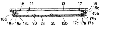
제4도는 제2도의 Ⅳ-Ⅳ선을 자른 단면도.4 is a cross-sectional view taken along the line IV-IV of FIG.
제5도는 블로킹형 인버터의 회로도.5 is a circuit diagram of a blocking inverter.
제6도는 본 발명의 다른 실시예인 평면형광등의 분해도.6 is an exploded view of a planar fluorescent lamp according to another embodiment of the present invention.
제7도는 제6도에 도시된 평면형광등의 평면도.7 is a plan view of the planar fluorescent lamp shown in FIG.
제8도는 제7도의 Ⅷ-Ⅷ선을 자른 단면도.8 is a cross-sectional view taken along the line VII-VII of FIG. 7.
제9도는 형광층으로 코팅된 배면판의 부분횡단면도.9 is a partial cross-sectional view of the back plate coated with a fluorescent layer.
제10도는 형광층으로 코팅된 또다른 배면판의 부분 횡단면도.10 is a partial cross sectional view of another backplate coated with a fluorescent layer.
* 도면의 주요부분에 대한 부호의 설명* Explanation of symbols for main parts of the drawings
11 : 평면 형광등 13 : 전면판11: flat fluorescent lamp 13: front panel
15 : 배면금속판 17, 18 : 전극15:
20 : 방전공간 23 : 광확산층20: discharge space 23: light diffusion layer
25 : 광반사층 35 : 트랜지스터25: light reflection layer 35: transistor
37 : 축전기37: capacitor
본 발명은 일반적인 형광등에 관련된 것으로, 특히 액정표시장치, 예를들어 액정텔레비젼에서 특정부분을 균등한 밝기로 비추는 배면등(backlingting)으로서 사용되는 평면형광등에 관한 것이다.BACKGROUND OF THE INVENTION 1. Field of the Invention [0001] The present invention relates generally to fluorescent lamps, and more particularly to planar fluorescent lamps used as backlighting for illuminating certain parts of a liquid crystal television with equal brightness.
종래의 형광등은 예를들어 일본국 특허공개공보(공개번호 : 62-208537, 공개일 : 87. 9.12)에 개시되어 있다.Conventional fluorescent lamps are disclosed, for example, in Japanese Patent Application Laid-Open (Publication No .: 62-208537, Publication Date: 87. 9.12).
종래의 평면 형광등은 평면형태의 장방형 정면유리와 평면 형태의 장방형 배면유리로서 구성되어 있다.Conventional planar fluorescent lamps are configured as a planar rectangular front glass and a planar rectangular rear glass.
프레임 형태의 스페이서가 정면유리와 배면유리 사이에 위치되고 용융점이 낮은 백옥(白玉 : frit : 용융가능한 磁製 혼합물로서 식기용, 욕조등의 금속표면용 유약이나 에나멜 제조에 쓰임) 유리에 의해 공기가 통하지 않도록 밀폐된 채 납땜되어 있다.Frame-shaped spacers are located between the front glass and the back glass, and have a low melting point of white jade (melt), which is used for preparing glazes or enamels for metal surfaces such as tableware and bathtubs. It is sealed and soldered to prevent passage.
그러므로 전면유리와 배면유리가 스페이서에 의해 지지되므로 적당한 방전공간이 두 유리사이에 구성된다.Therefore, the front glass and the back glass are supported by the spacer, so a suitable discharge space is formed between the two glasses.
한쌍의 냉음극이 서로 떨어져서 방전공간에 생겨 그 사이의 방전로를 유지한다.A pair of cold cathodes are separated from each other and formed in the discharge space to maintain the discharge path therebetween.
한쌍의 터미널 플레이트는 각각 대응하는 냉음극에 연결되며, 스페이서를 통하여 공기가 통하지 않도록 램프로 부터 유도형성 된다.The pair of terminal plates are each connected to a corresponding cold cathode and are inductively formed from the lamp to prevent air from passing through the spacers.
크세논, 크립톤, 알곤, 네온, 헬륨중에서 적어도 하나의 희유기체가 램프내로 밀봉된다.At least one rare gas of xenon, krypton, argon, neon, helium is sealed into the lamp.
다수의 수은 역시 희유기체와 함께 램프내에 밀봉된다. 형광층이 전면유리의 뒤쪽에 구성된다.Many mercury is also sealed in the lamp with rare gases. A fluorescent layer is built behind the windshield.
상기의 종래 평면 평광등은 램프가 전면유리, 배면유리와 프레임형태의 스페이서로 구성되므로 램프의 강도가 기압에 견딜 수 있는 전면유리와 배면유리를 형성하기 위해 비교적 두꺼운 유리가 필요하였다.Since the conventional planar flat lamp is composed of a front glass, a back glass and a spacer in the form of a frame, a relatively thick glass is required to form a windshield and a back glass whose strength of the lamp can withstand air pressure.
그러나 그런 두꺼운 유리는 램프의 무게와 두께를 증가시키는 원인이 되었다.However, such thick glass caused the lamp to increase in weight and thickness.
따라서 본 발명의 목적은 평면형광등의 두께를 줄이고자 하는 것이다.Accordingly, an object of the present invention is to reduce the thickness of a planar fluorescent lamp.
본 발명의 또 다른 목적은 평면형광등의 무게를 줄이고자 하는 것이다.Another object of the present invention is to reduce the weight of a planar fluorescent lamp.
이 목적을 달성하기 위하여 평면형광등은 투과할 수 있는 전면판과, 전면판과 배면판 사이에 방전공간을 형성하기 위한 배면판으로 구성된다. 램프는 또한 음극쌍 사이에 방전을 일으키기 위하여 방전공간 내에서 서로 반대위치에 구성되는 한쌍의 냉음극을 구성한다. 희유기체를 포함한 채움물질이 방전공간으로 공급된다.In order to achieve this object, a planar fluorescent lamp is composed of a front plate that can transmit and a back plate for forming a discharge space between the front plate and the back plate. The lamp also constitutes a pair of cold cathodes arranged in opposite positions in the discharge space to cause discharge between the cathode pairs. Filler containing rare gas is supplied to the discharge space.
배면금속판은 평판부, 평판부의 외측 가장자리로 부터 일체로 수직으로 연장형성된 주변벽부와 주변벽부의 연장된 가장 자리로 부터 일체로 외측으로 형성된 플랜지 부로 구성된다. 광확산층은 방전공간으로 노출되는 배면금속판의 표면위에 구성된다. 또한 광반사층은 광확산층위에 형성될 수 있다.The back metal plate is composed of a flat plate portion, a peripheral wall portion integrally formed vertically from the outer edge of the flat plate portion, and a flange portion integrally formed outward from the extended edge of the peripheral wall portion. The light diffusion layer is formed on the surface of the back metal plate exposed to the discharge space. In addition, the light reflection layer may be formed on the light diffusion layer.
형광층은 방전공간으로 노출되는 전면판의 표면에 구성되거나 방전공간으로 노출되는 배면금속판의 표면에 구성된다. 제1도에서 제4도까지는 본 발명의 신호된 실시예를 나타낸다.The fluorescent layer is configured on the surface of the front plate exposed to the discharge space or on the surface of the back metal plate exposed to the discharge space. 1 through 4 show signalized embodiments of the present invention.
평면형광등(11)은 빛이 통과할 수 있는 평면인 전면판(13), 금속재의 배면판(15)과 한쌍의 전극(17)(18)으로 구성되어 있다. 전면판(13)은 자외선을 투과하지 않는 유리, 예를들면 소다석회 유리나 납유리등의 장방형 유리로 형성되어 있다. 금속재의 배면판(15)은 유리와 비슷한 열팽창계수를 갖는 금속, 즉 스테인레스 강이나 니켈등으로 압축공정에 의해 장방형접시 모양으로 만들어진다. 배면금속판(15)둘레의 벽부(15a)는 평판부(15b)의 가장자리와 일체로, 상방으로 연장형성된다.The planar
플랜지부(15c)는 주변벽부(15a)의 상단으로 부터 일체로, 상방으로 연장형성된다. 배면금속판(15)의 플랜지부(15c)는 유리납땜(19)에 의해 전면판(13)의 내면에 공기가 통하지 않게 접착되어 제3도와 제4도에서처럼 그 사이에 방전공간(20)을 형성한다. 형광층(21)은 전면판(13)의 내면에 구성된다. 유리광확산층(23)은 배면금속판(15)의 내면에 구성된다. 가시광선을 반사시키고 적외선을 투과시키는 티타니아(TiO2)와 같은 광반사층(25)은 유리광확산층(23)위에 형성된다.The
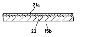
제9도에서와 같이 형광층(21a)은 전면판(13)의 내면에 형성되기 보다는 광반사층(25)위에 형성된다. 형광층(21a)이 배면금속판쪽에 구성된다면 램프(11)의 광도는 증가될 수 있다. 제10도에서도 역시 이 형광층(21a)은 광반사층(25)이 보이는 곳에 광확산층(23)위에 형성된다. 형광층(21a)이 배면금속판쪽에 구성된다면 램프(11)의 광도는 증가될 수 있다. 제1도와 제4도에서 한전극(17)은 방전공간(20)한쪽에 위치되며, 다른전극(18)은 방전공간(20)의 다른쪽에 위치되어 전극(17)과 전극(18)사이에 방전로를 형성한다.As shown in FIG. 9, the
각 전극(17)(18)은 속이비어 있는 음극형태의 냉음극이다. 각 전극(17)(18)은 프레임형태의 니켈측벽(17a)(18a)이 장방형의 니켈판(17b)(18b)으로부터 연장형성되어 있도록 구성되어 있다. 그래서 구멍(17c)이 측벽(17a)과 장방형판(17b)에 의해 구성되며 구멍(18c)역시 측벽(18a)과 장방형판(18b)에 의해 구성된다. 구멍(17c)과 구멍(18c)은 제4도에서처럼 서로 반대편에 구성되어 방전공간쪽으로 노출된다.Each
터미널 플레이트(17d)는 전극(17)으로 부터 연장형성되고, 배면금속판(15)의 주변벽부(15a)로 부터 유도 형성된다. 터미널플레이트(18d)는 전극(18)으로 부터 연장형성되고 역시 주변벽부(15a)로 부터 터미널플레이트(17d)와 같은 방향으로 유도형성된다. 제3도에서 한쌍의 구멍(27a)(27b)은 주변벽부중 한면(15a)의 반대 단부쪽에 구성된다. 터미널플레이트(17d)(18d)는 각각 대응구멍(27a)(27b)을 통과하여 구성된다. 각 구멍(27a)(27b)을 밀폐하기 위해 백옥유리(29a)(29b)가 사용된다.The
터미널플레이트(17a)(18d)와 주변벽부(15a)는 백옥유리(29a)(29b)에 의해 서로 전기적으로 분리되어 있다. 그래서 터미널플레이트(17d)(18d)는 각각 지지되는데, 즉 제4도에서 처럼 전극(17)(18)사이에 전면판(13), 배면판(15)사이의 방전공간(20)에 작은 갭이 생긴다.The
이 경우 스페이서(17e)(18e)가 각 전극(17)(18)과 배면금속판(15) 사이에 사용되어 갭을 유지시킬 수 있다. 제1,2,3도에서 처럼 배기파이프(31)가 납땜으로 한쌍의 터미널 플레이트(17d)(18d)가 지지되는 주변벽부(15a)의 한면에 접착된다. 배기파이프(31)는 바람직하기로는 유리재나 금속재로 만들어지는데, 예를들어 나오븀(Nb)과 같은 것으로 만들어진다. 램프(11)의 공기는 배출되고 크세논, 크립톤, 알곤, 네온, 헬륨 중 하나의 희유기체가 배기파이프(31)을 통해 램프(11)로 공급된다. 그후 배기파이프(31)를 밀폐한다. 비교적 적은양의 수은이 역시 램프내에 공급되고 밀봉된다.In this case,
상기의 평면형광등(11)은 사인파전원에 의해서 보다는 펄스전원에 의해 작동되어 전극(17)(18)사이의 방전을 균등하게 해준다. 램프(11)가 사인파 전원에 의해 작동될때에는 방전이 전극(17)(18)의 한부분에 집중된다. 이 경우 종래의 블로킹형 인버터(33)가 펄스전원으로서 사용된다. 블로킹형 인버터는 이 분야에서 잘 알려진 것이므로 상세한 구성과 작용은 생략한다. 제5도에서 NPN 트랜지스터(35)의 '온', '오프'는 콘덴서(37)에 의해 조절된다. 콘덴서(37)의 충전전압이 이러한 높은 수준에 이를때 트랜지스터(35)는 커져서 전류가 트랜스(39)의 제1의 감는부분(39a)을 통하여 흐른다. 트랜지스터(35)가 켜진후 즉시 저항기(41)를 통해 콘덴서(37)의 충전전압을 방전한다.The
그래서 트랜지스터(35)는 콘덴서(37)의 전압이 일정한 저수준으로 줄어들때 꺼져 제1의 감는부분(39a)를 통한 전류의 흐름이 방해된다. 그러므로 펄스전압이 제2 감는부분(39b)에 생긴다. 상기 작용이 되풀이되어 터미널플레이트(17d)(18d)를 통해 한쌍의(17)(18)에 펄스전압을 공급한다. 상기의 형광등(11)의 작용은 다음과 같다. 인버터(33)에 의해 생기는 펄스전압이 대응터미널플레이트(17d)(18d)를 통해 한쌍의 전극(냉음극)(17)(18)에 공급될때 전극(17)(18)사이에 글로우 방전이 일어난다.Thus, the
글로우 방전에 의해 자외선이 램프(11)에 채워진 희유기체(혹은 수은)로 부터 발생한다. 자외선은 전면판(13)의 뒷쪽에 형성된 형광층(21)을 여기(勵起)하여 램프(11)로 부터 나온 가시광선을 방사한다. 이때 방전공간(20)내에 생긴 자외선은 광반사층(25)에 의해 형광층(21)쪽으로 반사되어 형광층(21)의 여기계수를 증가시킨다. 가시광선은 전면판(13)의 전면으로 부터 방사된다. 그러므로 전면판(13)의 전면은 균일하게 빛을 발한다.Ultraviolet rays are generated from the rare gas (or mercury) filled in the
상기 형광등(11)이 액정표시 장치에 배면등으로서 사용될 때 액정표시 표면의 일정부분이 균등한 밝기로 완전히 밝혀진다. 상기 실시예에 따르면 배면판(15)이 얇은 금속으로 만들어 졌으므로 램프(13)의 두께는 줄어들 수 있다.When the
램프(13)의 무게 역시 기압에 의해 램프(13)가 깨짐이 없이 줄어들 수 있다.The weight of the
예를들어 종래의 평면램프가 4인치형의 액정 텔레비젼의 배면등(backlighting)으로서 사용될때 전면유리판과 배면유리 판의 90mm, 길이는 60mm이며, 두께는 3mm로서 3기압을 견딜 수 있다. 유리스페이서의 두께 3mm를 포함한 램프의 전체두께는 약 10mm이다. 램프의 무게는 약 230g이다.For example, when a conventional flat lamp is used as the backlighting of a 4 inch type liquid crystal television, the front glass plate and the rear glass plate are 90 mm long and 60 mm long, with a thickness of 3 mm, capable of withstanding 3 atmospheres. The total thickness of the lamp, including the glass spacer 3mm thick, is about 10mm. The lamp weighs about 230g.
반대로 상기 실시예에 의하면, 전면판(13)은 종래의 램프와 같은 것이나 배면판(15)은 스테인레스 강으로 만들어지며 그 두께는 종래의 램프와 같은 조건하에서 0.8mm이다. 그러므로 램프(11)의 전두께는 약 8mm이다. 램프(11)의 무게는 약 150g이다. 종래의 평면형광등과 비교하면 본 발명실시예인 램프(11)의 두께와 무게는 줄어들 수 있다.Conversely, according to this embodiment, the
상기 실시예에서, 광확산(23)과 광반사층(25)이 배면판(15)의 내면에 구성되고 방전공간(20)에 노출되어 있으므로 작동중에 배면판(15)에서 방전공간(20)으로 불순물이 방출되지 않는다.In the above embodiment, the
그러므로 램프(11)의 램프전압이 증가되는 것을 막는다. 더우기, 배면판(15)이 평판부(15b)와 주변벽부(15a)와 플랜지부(15c)를 포함하므로 플랜지부(15c)는 종래램프에 사용되던 유리스페이서를 사용하지 않고 전면판(13)에 직접 납땜된다. 그러므로 램프(11)의 조립부품수를 줄일 수 있고, 램프(11)의 납땜부분이 줄어들므로 노동효과가 증가될 수 있다. 램프(11)의 납땜부분이 줄어들므로 램프(11)를 실제 사용할동안 램프(11)로 부터 희유기체가 누출되는 것 역시 줄어들 것이다.Therefore, the lamp voltage of the
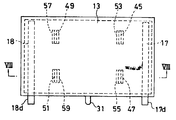
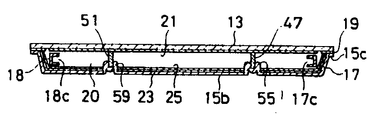
본 발명의 두번째 실시예는 제6-8도에서 설명된다. 도면에서 동일참조 번호가 전 실시예의 비슷한 부분에 적용된다. 그러므로 그에 대한 상세설명은 피한다. 최근에 액정 텔레비젼의 표시부분이 증가하는 경향이 있으므로 배면등(backlighting)즉 평면형광등의 발광면적이 증가될 필요가 있다.A second embodiment of the present invention is described in FIGS. 6-8. In the drawings, the same reference numerals apply to similar parts in the previous embodiments. Therefore, detailed descriptions thereof are avoided. In recent years, since the display portion of liquid crystal televisions tends to increase, the light emitting area of a backlight, i.e., a planar fluorescent lamp, needs to be increased.
상기의 전실시예에서 평면형광등(11)의 발광표면 부분이 증가된다면 배면금속판(15)의 중앙부분은 기압에 의해 구부러질 경향이 있다. 그래서 배면금속판(15)의 중앙부분과 전면판(13) 사이의 간격은 다양해지고 방전공간(20)의 체적역시 다양해진다. 제2실시예에서 배면판(15)이 변형되는 것을 막기 위해 4개의 간격부재(45)(47)(49)(51)가 사용된다. 간격부재(45)(47)(49)(51)는 전극(17)(18)사이의 방전을 방해하지 않도록 하기 위해 우선적으로 유리재로 만들어진다.In the above embodiment, if the light emitting surface portion of the
이경우 제6도에서와 같이 4개의 지지부분(53)(55)(57)(59)을 배면판(15)의 내면위 적당부분에 일체로 형성되어 각각 해당 간격부재(45)(47)(51)를 지지한다. 각 지지부분(53)(55)(57)(59)은 그 사이의 지지홈(53a)(55a)(57a)(59a)을 구서하는 병행한 돌출부를 포함한다. 그러므로 간격부재(45)(47)(49)(51)는 해당지지홈(53a)(55a)(57a)(59a)으로 삽입된다. 각 간격부재(45)(47)(49)(51)의 상단부분은 제8도에서와 같이 용융점이 낮은 백옥유리에 의해 전면판(13)이 내면에 납땜된다.In this case, as shown in FIG. 6, the four supporting
상기 제2실시예에 의하면 전면판(13)과 배면판(15)은 간격부재(45)(47)(49)(51)에 의해 보강되므로 배면판(15)은 변형 되지 않는다.According to the second embodiment, the
그러므로 전면판(13)과 배면판(19) 사이의 간격은 일정하게 유지된다. 더우기 전면판(13)과 배면판(15)이 간격부재(45)(47)(49)(51)에 의해 보강되므로 유리재로 된 전면판(13)의 두께는 제1 실시예와 비교할때 필요한 기계적 강도 범위내에서 줄어들 수 있다.Therefore, the gap between the
제2 실시예의 간격부재 때문에 평면형광등(13)의 두께를 더욱 줄일 수 있다. 상기 실시예들에서 전면판(13)은 유리재로 만들어지나 가벼운 투과성 세라믹이나 플라스틱으로도 만들 수 있다. 더우기, 평면형광등(11)의 외형은 제1,2 실시예의 장방형외에 적당한 형태로 만들 수 있다. 평면금속판이 배면판으로서 사용될 수 있다.The thickness of the
이 경우 프레임형태의 유리 스페이서가 전면판과 배면판 사이의 방전공간을 형성하기 위해 사용될 수 있다. 본 발명은 특별실시예를 예로써 기술되었으나 본 발명의 원리를 기초로 한 다른 실시예도 본 기술분야에서 통상의 기술을 가진자에게는 가능하다.In this case, a glass spacer in the form of a frame may be used to form a discharge space between the front plate and the back plate. Although the present invention has been described by way of example of specific embodiments, other embodiments based on the principles of the present invention are possible for those skilled in the art.
Claims (14)
Applications Claiming Priority (3)
| Application Number | Priority Date | Filing Date | Title |
|---|---|---|---|
| JP69781 | 1981-05-09 | ||
| JP63-69781 | 1988-03-25 | ||
| JP63069781A JPH01243361A (en) | 1988-03-25 | 1988-03-25 | Plane-shaped fluorescent lamp |
Publications (2)
| Publication Number | Publication Date |
|---|---|
| KR890015325A KR890015325A (en) | 1989-10-28 |
| KR920001846B1 true KR920001846B1 (en) | 1992-03-05 |
Family
ID=13412649
Family Applications (1)
| Application Number | Title | Priority Date | Filing Date |
|---|---|---|---|
| KR1019890003540A KR920001846B1 (en) | 1988-03-25 | 1989-03-21 | Flat surface fluorescent lamp |
Country Status (4)
| Country | Link |
|---|---|
| JP (1) | JPH01243361A (en) |
| KR (1) | KR920001846B1 (en) |
| DE (1) | DE3909715A1 (en) |
| GB (1) | GB2217515A (en) |
Families Citing this family (15)
| Publication number | Priority date | Publication date | Assignee | Title |
|---|---|---|---|---|
| DE69028609T2 (en) * | 1989-12-18 | 1997-05-15 | Toshiba Lighting & Technology | Fluorescent lamp device |
| JPH0498259U (en) * | 1990-07-21 | 1992-08-25 | ||
| FR2696816B1 (en) * | 1992-10-12 | 1994-12-30 | Valeo Vision | Glow discharge lighting or signaling device for a motor vehicle. |
| US5479069A (en) * | 1994-02-18 | 1995-12-26 | Winsor Corporation | Planar fluorescent lamp with metal body and serpentine channel |
| US5811925A (en) * | 1996-12-04 | 1998-09-22 | Matsushita Electric Works Research And Development Laboratory, Inc. | Integrally molded flat compact fluorescent lamp |
| US5903096A (en) * | 1997-09-30 | 1999-05-11 | Winsor Corporation | Photoluminescent lamp with angled pins on internal channel walls |
| US5914560A (en) * | 1997-09-30 | 1999-06-22 | Winsor Corporation | Wide illumination range photoluminescent lamp |
| US6100635A (en) * | 1998-02-02 | 2000-08-08 | Winsor Corporation | Small, high efficiency planar fluorescent lamp |
| US6091192A (en) * | 1998-02-02 | 2000-07-18 | Winsor Corporation | Stress-relieved electroluminescent panel |
| US6114809A (en) * | 1998-02-02 | 2000-09-05 | Winsor Corporation | Planar fluorescent lamp with starter and heater circuit |
| US6075320A (en) * | 1998-02-02 | 2000-06-13 | Winsor Corporation | Wide illumination range fluorescent lamp |
| US6127780A (en) * | 1998-02-02 | 2000-10-03 | Winsor Corporation | Wide illumination range photoluminescent lamp |
| GB9803587D0 (en) | 1998-02-23 | 1998-04-15 | Smiths Industries Plc | Gas discharge lamps and systems |
| JP4049486B2 (en) * | 1999-08-11 | 2008-02-20 | 三洋電機株式会社 | Showcase |
| JP4493064B2 (en) * | 2000-10-06 | 2010-06-30 | 日本電気株式会社 | Flat fluorescent lamp fixing structure and liquid crystal display device |
Family Cites Families (8)
| Publication number | Priority date | Publication date | Assignee | Title |
|---|---|---|---|---|
| NL35713C (en) * | 1932-05-23 | |||
| GB701589A (en) * | 1949-12-10 | 1953-12-30 | Loewe Opta Ag | Electric discharge tube for emission of visible light |
| FR2233708A1 (en) * | 1973-06-13 | 1975-01-10 | Central Laboratoire Eclairage | Low pressure metal vapour discharge lamp - has metal envelope with sealed in electrodes in two opposite envelope points |
| US4272702A (en) * | 1977-01-28 | 1981-06-09 | Stanley Electric Co., Ltd. | Fluorescent lamp |
| US4303847A (en) * | 1979-06-22 | 1981-12-01 | Lucitron, Inc. | Flat-panel display with gas-impervious metallic sheet forming part of sealed enclosure |
| US4325489A (en) * | 1980-04-17 | 1982-04-20 | Rca Corporation | Envelope for flat panel display devices |
| AU6841387A (en) * | 1986-01-17 | 1987-08-14 | Sidefact Ltd. | Flat light source |
| DE3617918A1 (en) * | 1986-05-28 | 1987-12-03 | Heimann Gmbh | Discharge lamp |
-
1988
- 1988-03-25 JP JP63069781A patent/JPH01243361A/en active Pending
-
1989
- 1989-03-21 KR KR1019890003540A patent/KR920001846B1/en active IP Right Grant
- 1989-03-23 DE DE3909715A patent/DE3909715A1/en active Granted
- 1989-03-23 GB GB8906830A patent/GB2217515A/en not_active Withdrawn
Also Published As
| Publication number | Publication date |
|---|---|
| DE3909715C2 (en) | 1991-11-14 |
| KR890015325A (en) | 1989-10-28 |
| GB8906830D0 (en) | 1989-05-10 |
| DE3909715A1 (en) | 1989-10-05 |
| GB2217515A (en) | 1989-10-25 |
| JPH01243361A (en) | 1989-09-28 |
Similar Documents
| Publication | Publication Date | Title |
|---|---|---|
| KR920001846B1 (en) | Flat surface fluorescent lamp | |
| KR960014525B1 (en) | Flat fluorescent lamp for liquid crystal display | |
| KR100395976B1 (en) | Gas discharge lamp with dielectrically impeded electrodes | |
| KR20080001227A (en) | Apparatus for fixing a lamp of the back-light | |
| KR20060014322A (en) | Backlight assembly and liquid crystal display device having the same | |
| KR100417432B1 (en) | Flat reflector lamp for dielectrically inhibited discharges with spacers | |
| JP2006108065A (en) | Backlight assembly and liquid crystal display provided with it | |
| JP2000082441A (en) | Flat plate light source | |
| JP2006147516A (en) | Flat fluorescent lamp and liquid crystal display device having the same | |
| JPH0278147A (en) | Planar fluorescent lamp | |
| KR100322057B1 (en) | Surface light source | |
| JPH0927298A (en) | Flat light source | |
| JPS62103960A (en) | Flat fluorescent lamp | |
| KR100588710B1 (en) | Internally channeled glass envelope with molded edge for affixing attachments | |
| KR20060021150A (en) | Flat fluorescent lamp and liquid crystal display device having the same | |
| JP2001155527A (en) | Back light device and liquid crystal display device | |
| JP2007087901A (en) | Flat discharge lamp lighting system | |
| JP2006093072A (en) | Flat plate fluorescent lamp and liquid crystal display device having same | |
| KR20090025521A (en) | Electrode material and method for preparing the same and and backlight unit having the same | |
| JPH03110750A (en) | Flat surface emission type electric discharge lamp | |
| JPH054200Y2 (en) | ||
| JPH02309552A (en) | Cold-cathode type discharge lamp | |
| JPH07240180A (en) | Fluorescent lamp | |
| JPH01163955A (en) | Flat fluorescent lamp | |
| JPH11307049A (en) | Fluorescent lamp and lighting system |
Legal Events
| Date | Code | Title | Description |
|---|---|---|---|
| A201 | Request for examination | ||
| E902 | Notification of reason for refusal | ||
| G160 | Decision to publish patent application | ||
| E701 | Decision to grant or registration of patent right | ||
| NORF | Unpaid initial registration fee |