KR910010087B1 - Change - speed gearbox - Google Patents
Change - speed gearbox Download PDFInfo
- Publication number
- KR910010087B1 KR910010087B1 KR1019870700679A KR870700679A KR910010087B1 KR 910010087 B1 KR910010087 B1 KR 910010087B1 KR 1019870700679 A KR1019870700679 A KR 1019870700679A KR 870700679 A KR870700679 A KR 870700679A KR 910010087 B1 KR910010087 B1 KR 910010087B1
- Authority
- KR
- South Korea
- Prior art keywords
- gear
- shaft
- transmission
- wheel
- driven
- Prior art date
Links
Images


Classifications
-
- F—MECHANICAL ENGINEERING; LIGHTING; HEATING; WEAPONS; BLASTING
- F16—ENGINEERING ELEMENTS AND UNITS; GENERAL MEASURES FOR PRODUCING AND MAINTAINING EFFECTIVE FUNCTIONING OF MACHINES OR INSTALLATIONS; THERMAL INSULATION IN GENERAL
- F16H—GEARING
- F16H3/00—Toothed gearings for conveying rotary motion with variable gear ratio or for reversing rotary motion
- F16H3/02—Toothed gearings for conveying rotary motion with variable gear ratio or for reversing rotary motion without gears having orbital motion
- F16H3/08—Toothed gearings for conveying rotary motion with variable gear ratio or for reversing rotary motion without gears having orbital motion exclusively or essentially with continuously meshing gears, that can be disengaged from their shafts
-
- F—MECHANICAL ENGINEERING; LIGHTING; HEATING; WEAPONS; BLASTING
- F16—ENGINEERING ELEMENTS AND UNITS; GENERAL MEASURES FOR PRODUCING AND MAINTAINING EFFECTIVE FUNCTIONING OF MACHINES OR INSTALLATIONS; THERMAL INSULATION IN GENERAL
- F16H—GEARING
- F16H37/00—Combinations of mechanical gearings, not provided for in groups F16H1/00 - F16H35/00
- F16H37/02—Combinations of mechanical gearings, not provided for in groups F16H1/00 - F16H35/00 comprising essentially only toothed or friction gearings
- F16H37/04—Combinations of toothed gearings only
- F16H37/042—Combinations of toothed gearings only change gear transmissions in group arrangement
- F16H37/046—Combinations of toothed gearings only change gear transmissions in group arrangement with an additional planetary gear train, e.g. creep gear, overdrive
-
- F—MECHANICAL ENGINEERING; LIGHTING; HEATING; WEAPONS; BLASTING
- F16—ENGINEERING ELEMENTS AND UNITS; GENERAL MEASURES FOR PRODUCING AND MAINTAINING EFFECTIVE FUNCTIONING OF MACHINES OR INSTALLATIONS; THERMAL INSULATION IN GENERAL
- F16H—GEARING
- F16H3/00—Toothed gearings for conveying rotary motion with variable gear ratio or for reversing rotary motion
- F16H3/02—Toothed gearings for conveying rotary motion with variable gear ratio or for reversing rotary motion without gears having orbital motion
- F16H3/08—Toothed gearings for conveying rotary motion with variable gear ratio or for reversing rotary motion without gears having orbital motion exclusively or essentially with continuously meshing gears, that can be disengaged from their shafts
- F16H3/087—Toothed gearings for conveying rotary motion with variable gear ratio or for reversing rotary motion without gears having orbital motion exclusively or essentially with continuously meshing gears, that can be disengaged from their shafts characterised by the disposition of the gears
- F16H3/093—Toothed gearings for conveying rotary motion with variable gear ratio or for reversing rotary motion without gears having orbital motion exclusively or essentially with continuously meshing gears, that can be disengaged from their shafts characterised by the disposition of the gears with two or more countershafts
- F16H3/097—Toothed gearings for conveying rotary motion with variable gear ratio or for reversing rotary motion without gears having orbital motion exclusively or essentially with continuously meshing gears, that can be disengaged from their shafts characterised by the disposition of the gears with two or more countershafts the input and output shafts being aligned on the same axis
-
- F—MECHANICAL ENGINEERING; LIGHTING; HEATING; WEAPONS; BLASTING
- F16—ENGINEERING ELEMENTS AND UNITS; GENERAL MEASURES FOR PRODUCING AND MAINTAINING EFFECTIVE FUNCTIONING OF MACHINES OR INSTALLATIONS; THERMAL INSULATION IN GENERAL
- F16H—GEARING
- F16H3/00—Toothed gearings for conveying rotary motion with variable gear ratio or for reversing rotary motion
- F16H3/02—Toothed gearings for conveying rotary motion with variable gear ratio or for reversing rotary motion without gears having orbital motion
- F16H3/08—Toothed gearings for conveying rotary motion with variable gear ratio or for reversing rotary motion without gears having orbital motion exclusively or essentially with continuously meshing gears, that can be disengaged from their shafts
- F16H3/12—Toothed gearings for conveying rotary motion with variable gear ratio or for reversing rotary motion without gears having orbital motion exclusively or essentially with continuously meshing gears, that can be disengaged from their shafts with means for synchronisation not incorporated in the clutches
- F16H2003/123—Toothed gearings for conveying rotary motion with variable gear ratio or for reversing rotary motion without gears having orbital motion exclusively or essentially with continuously meshing gears, that can be disengaged from their shafts with means for synchronisation not incorporated in the clutches using a brake
-
- F—MECHANICAL ENGINEERING; LIGHTING; HEATING; WEAPONS; BLASTING
- F16—ENGINEERING ELEMENTS AND UNITS; GENERAL MEASURES FOR PRODUCING AND MAINTAINING EFFECTIVE FUNCTIONING OF MACHINES OR INSTALLATIONS; THERMAL INSULATION IN GENERAL
- F16H—GEARING
- F16H61/00—Control functions within control units of change-speed- or reversing-gearings for conveying rotary motion ; Control of exclusively fluid gearing, friction gearing, gearings with endless flexible members or other particular types of gearing
- F16H61/04—Smoothing ratio shift
- F16H61/0403—Synchronisation before shifting
- F16H2061/0407—Synchronisation before shifting by control of clutch in parallel torque path
-
- Y—GENERAL TAGGING OF NEW TECHNOLOGICAL DEVELOPMENTS; GENERAL TAGGING OF CROSS-SECTIONAL TECHNOLOGIES SPANNING OVER SEVERAL SECTIONS OF THE IPC; TECHNICAL SUBJECTS COVERED BY FORMER USPC CROSS-REFERENCE ART COLLECTIONS [XRACs] AND DIGESTS
- Y10—TECHNICAL SUBJECTS COVERED BY FORMER USPC
- Y10T—TECHNICAL SUBJECTS COVERED BY FORMER US CLASSIFICATION
- Y10T74/00—Machine element or mechanism
- Y10T74/19—Gearing
- Y10T74/19219—Interchangeably locked
- Y10T74/19233—Plurality of counter shafts
-
- Y—GENERAL TAGGING OF NEW TECHNOLOGICAL DEVELOPMENTS; GENERAL TAGGING OF CROSS-SECTIONAL TECHNOLOGIES SPANNING OVER SEVERAL SECTIONS OF THE IPC; TECHNICAL SUBJECTS COVERED BY FORMER USPC CROSS-REFERENCE ART COLLECTIONS [XRACs] AND DIGESTS
- Y10—TECHNICAL SUBJECTS COVERED BY FORMER USPC
- Y10T—TECHNICAL SUBJECTS COVERED BY FORMER US CLASSIFICATION
- Y10T74/00—Machine element or mechanism
- Y10T74/19—Gearing
- Y10T74/19219—Interchangeably locked
- Y10T74/19377—Slidable keys or clutches
- Y10T74/19386—Multiple clutch shafts
- Y10T74/19391—Progressive
- Y10T74/19395—Keys simultaneously slidable
-
- Y—GENERAL TAGGING OF NEW TECHNOLOGICAL DEVELOPMENTS; GENERAL TAGGING OF CROSS-SECTIONAL TECHNOLOGIES SPANNING OVER SEVERAL SECTIONS OF THE IPC; TECHNICAL SUBJECTS COVERED BY FORMER USPC CROSS-REFERENCE ART COLLECTIONS [XRACs] AND DIGESTS
- Y10—TECHNICAL SUBJECTS COVERED BY FORMER USPC
- Y10T—TECHNICAL SUBJECTS COVERED BY FORMER US CLASSIFICATION
- Y10T74/00—Machine element or mechanism
- Y10T74/19—Gearing
- Y10T74/19219—Interchangeably locked
- Y10T74/19377—Slidable keys or clutches
- Y10T74/19386—Multiple clutch shafts
- Y10T74/194—Selective
Abstract
내용 없음.No content.
Description
다단계 변속기Multi-level gearbox
[도면의 간단한 설명][Brief Description of Drawings]
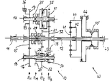
제1도는 후접속기어장치를 가진 다단계 변속기의 개략도이고,1 is a schematic diagram of a multi-stage transmission with a rear connection gear device,
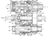
제2도는 제1도의 다단계 변속기의 구조적인 실시예이며,2 is a structural embodiment of the multistage transmission of FIG.
제3a도는 제2도의 선 Ⅲ-Ⅲ을 따라 본 부분단면도이고,3a is a partial cross-sectional view taken along the line III-III of FIG. 2,
제3b도는 제3a도의 또다른 실시예를 보여주는 도면이다.FIG. 3B is a view showing another embodiment of FIG. 3A.
[발명의 상세한 설명]Detailed description of the invention
본 발명은 청구범위 제1항의 상위개념에 전제하고 있고 오스트리아 특허 51824에 공지된 바와 같은 3개의 전진속도 및 하나의 후진속도용 다단계 변속기에 관한 것이다.The present invention is based on the high-level concept of claim 1 and relates to a three-stage transmission for three forward speeds and one reverse speed as known from Austrian patent 51824.
따라서 본 발명은 구동축 및 이 구동축과 클러치되고 동축으로 설치된 피동축 및 다수의 2차축을 갖는 다단계 변속기를 기초로 한다. 상기 축상에는 서로 맞물린 다수의 기어그룹이 설치된다. 변속을 위해서 이동할 수 있는 변속슬리브가 사용되는데 이 변속슬리브는 클러치로서 형성된다. 변속슬리브중 하나는 피동축을 구동축에 직접 클러치하는데 사용된다. 다른 변속슬리브의 각각에 의해 하나의 축상에 느슨하게 놓여진 기어가 그 축에 클러치되기 때문에 각 경우에 기어쌍으로만 작용하며, 이 기어쌍의 직경(및 상응하는 기어잇수)이 각각의 의도한 바의 기어비를 만들어낸다.Accordingly, the present invention is based on a drive shaft and a multistage transmission having a driven shaft and a plurality of secondary shafts clutched coaxially with the drive shaft. A plurality of gear groups engaged with each other are installed on the shaft. A shifting sleeve is used for shifting, which is formed as a clutch. One of the shifting sleeves is used to clutch the driven shaft directly to the drive shaft. Since each gear shifted loosely on one axis is clutched to that axis by each of the other shifting sleeves, it acts only as a gear pair in each case, and the diameter (and corresponding number of gear teeth) of this gear pair is Create a gear ratio.
공지된 다단계 변속기는 서로 동축으로 배치된 구동축 및 피동축외에 3개의 2차축을 갖는다; 기어들은 4개의 기어그룹으로 세분된다; 따라서 4개의 평면, 즉 2개의 전반면과 2개의 후반면을 갖는다. 변속슬리브는 모두 변속기의 중심영역내에, 즉 실제로는 소위 슬리브평면내에 설치되는데, 이 슬리브평면은 제2 및 제3 휘일평면사이에 놓인다. 이러한 공지된 구조에서는 이미 공간을 절약할 수 있는 구조를 찾으려고 시도했었다. 그러나 공지된 변속기는 상술한 바와 같이 4개의 휘일평면이 필요하기 때문에 비교적 큰 전체길이를 갖는다.Known multi-stage transmissions have three secondary shafts in addition to the drive shaft and the driven shaft disposed coaxially with each other; The gears are subdivided into four gear groups; Thus it has four planes, two first half and two second half. The shift sleeves are all installed in the central area of the transmission, ie in the so-called sleeve plane, which lies between the second and third wheel planes. This known structure has already attempted to find a structure that can save space. However, known transmissions have a relatively large overall length since four wheel planes are required as described above.
본 발명의 목적은 축방향 길이를 더 줄일 수 있도록 전술한 종래의 다단계 변속기를 개선하는데 있다. 또한 필요시에 소위 중심동기화가 다시 기어-전체길이를 확대함이 없이 이루어져야 한다.It is an object of the present invention to improve the conventional multistage transmission described above to further reduce the axial length. In addition, if necessary, so-called central synchronization should be achieved again without enlarging the gear-total length.
이러한 목적은 공지된 다단계 변속기를 본 발명에 따라 개선함으로써 이루어진다.This object is achieved by improving the known multistage transmission according to the invention.
본 발명에 따라 단지 3개의 기어그룹만을 필요로 하면서도 변속슬리브의 배열이 하나의 평면으로 유지될 수 있기 때문에 변속기의 축방향 길이가 최소로 이루어질 수 있다. 특히 짧은 길이로 인해 전체길이가 통상의 크기, 예를들면 자동차내에 설치하기 위한 크기를 초과하지 않으면서 이러한 변속기(독일연방공화국 특허 DE-PS 21 37 440에 공지된 바와 같은)에 기어의 수를 증가시키도록 유성기어장치가 접속될 수 있다. 따라서 본 발명에 따른 변속기의 실제적인 장점은 기어비의 범위를 가급적 확대시키기 위해 제2의 기어장치를 조합할 수 있다는데 있다.The axial length of the transmission can be made to a minimum because the arrangement of the shifting sleeves can be maintained in one plane while only requiring three gear groups in accordance with the invention. Due to the particularly short length, the number of gears in this transmission (as known in the Federal Republic of Germany Patent DE-PS 21 37 440) can be adjusted so that the overall length does not exceed the usual size, for example for installation in vehicles. The planetary gear device can be connected to increase. Therefore, a practical advantage of the transmission according to the present invention is that it is possible to combine the second gear device in order to extend the range of the gear ratio as much as possible.
이러한 견지에서 볼 때 본 발명의 특별한 실시예에 따라 슬리브평면이 제1 및 제2휘일평면사이에 놓이는 경우가 특히 유리하다. 또한 이 경우에 제2차축상에 느슨하게 놓여진 후단-기어를 이 2차축과 클러치하는 클러치부재가 이 축상에 회전하도록 놓인 또 다른 2차휘일을 통해 구현되는 것이 바람직하다.In view of this, it is particularly advantageous if the sleeve plane lies between the first and second wheel planes according to a particular embodiment of the invention. Also in this case it is preferred that the clutch member for clutching the rear-gear gear loosely laid on the second axle to the second axle is rotated on this axis by another secondary wheel.
각각의 변속슬리브가 그 고유의 동기화장치를 갖는 것이 아니라 그것 대신에 예를들면 독일연방공화국 공개공보 DE-PS 30 21 489에 공지된 바와 같은 소위 중심-동기화가 이루어짐으로써 변속기의 전체길이가 또 다시 축소될 수 있다. 중심-동기화는 한편으로는 후진변속시 구동축의 기어부를 가속하기 위한 미끄럼 클러치를 갖고 다른 한편으로는 고속변속시 구동축의 기어부를 지연시키기 위한 브레이크를 갖는다. 본 발명의 또 다른 실시에서는 두 번째 2차축상에 있는 중심 동기화에 속하는 미끄럼클러치가 중앙휘일평면내에 설치된다. 왜냐하면 이 위치에서는 미끄럼클러치에 부가적인 장소가 필요하지 않기 때문이다. 바람직하게는 브레이크가 구동축 축베어링의 평면내에 설치되기 때문에 이것을 위한 변속기-전체길이를 확대시킬 필요가 없다.Each transmission sleeve does not have its own synchronizing device, but instead the entire length of the transmission is again achieved, for example by the so-called center-synchronization, as known from DE-PS 30 21 489. Can be reduced. The center-synchronization has, on the one hand, a sliding clutch for accelerating the gear part of the drive shaft during the reverse shift, and on the other hand a brake for delaying the gear part of the drive shaft during the high speed shift. In another embodiment of the present invention, a slip clutch belonging to the center synchronization on the second secondary axis is installed in the central wheel plane. Because this position does not require an additional place for the slip clutch. It is not necessary to enlarge the transmission-total length for this, since the brake is preferably installed in the plane of the drive shaft shaft bearing.
본 발명의 실시예를 첨부한 도면을 참고로 상세히 설명하면 다음과 같다.When described in detail with reference to the accompanying drawings an embodiment of the present invention.
제1 및 제2의 왼쪽편에는 공지된 구동축(11)이 도시되어 있는데, 이 구동축에는 일반적으로 여기에는 도시되지 않은 클러치가 연결되어 있다. 피동축(12)은 구동축(11)과 동축을 이루면 마찬가지로 적합한 방식으로 지지되어 있다. 또한 도시되지 않은 기어케이스내에는 첫 번째 2차축(13)과 두 번째 2차축(14)이 지지되어 있다. 구동축(11)상에는 기어(15)가 놓이는데 이 기어는 이 축과 단단하게 연결되고 각각의 기어(16) 및 (17)와 맞물려진다. 기어(16) 및 (17)의 측면은 2차축(13) 및 (14)상에 놓이고 이 축과 단단히 연결된다. 피동축(12)상에는 제1 및 제2피동기어(21) 및 (32)가 놓이며, 이것들중 첫 번째, 즉 기어(21)는 축(12)상에 느슨하게 놓이는 반면에 두 번째, 즉 기어(32)는 축(12)과 단단히 연결된다. 느슨하게 놓여있는 첫 번째 피동기어(21)는 2차축(13)상에 단단하게 놓여있는 2차휘일(22)과 맞물려진다. 제2피동기어(32)는 제1도에 도식적으로 표시된 역기어(33)과 맞물려지고, 이 역기어의 측면은 2차축(13)상에 느슨하게 지지된 기어(34)와 맞물려진다. 변속슬리브(24)를 통해 기어(34)는 2차축(13)과 단단하게 연결될 수 있다. 다른 한편으로는 제2피동기어(32)는 기어(31)과 맞무려지는데, 이 기어(31)는 두 번째 2차축(14)상에 느슨하게 놓이고 변속슬리브(25)를 통해 2차축(14)과 단단히 연결될 수 있다.
2중 변속슬리브로 형성된 제3변속슬리브(23)는 피동축(12)이 선택적으로 구동축(11)과 직접 연결되거나 피동축상에 느슨하게 놓여진 제1피동기어(21)와 연결되도록 하는데, 이때 제1피동기어(21)는 2차축(13)상에 놓여있는 2차휘일(22)과 맞물려진다. 변속슬리브(23),(24),(25)의 이동은 공지된 방식으로 도시되지 않은 포크형 변속기구에 의해 행해진다.The
기어(15),(16) 및 (17)는 휘일평면 E1내에 놓이고, 기어(21) 및(22)는 제2휘일평면 E2내에 놓이며 기어(31),(32),(33) 및 (34)는 제3휘일평면 E3내에 놓인다. 도시된 바와 같이 3개의 변속슬리브(23),(24) 및 (25)는 전체적으로 하나의 동일한 슬리브평면 EM내에 놓이며, 이 슬리브평면 EM은 제시된 실시예에서 제1 및 제2휘일평면 E1및 E2사이에 놓인다. 후단기어(34)를 접속하기 위한 변속슬리브(24)는 2차휘일(22)에 의해 최소한 3개의 볼트(26)와 돌출하고, 이러한 구조로 인해 후진속도용 변속슬리브(24)가 후진기어(34)와 마찬가지로 2차휘일의 다른면에 설치될 수 있기 때문에 변속슬리브(24)는 두 개의 다른 변속슬리브(23) 및 (25)와 같이 동일한 평면에 놓이는 반면 기어(34)는 외부휘일평면 E3내에 놓인다. 제3a도 및 제3b도가 제시하는 바와 같이 볼트(26)는 변속슬리브(24)에 의해 기어(34)의 이내로 밀려진다. 제3a도에 따라 기어 이사이에 볼트(26)를 위한 특별한 인출부(26a)가 마련되는 반면에 제3b도에 따른 볼트는 간단히 기어 이사이의 공간내로 이동된다.
도면에서 맞은편에 있는 2차축(14)상에는 미끄럼마찰클러치(35)가 설치되고, 이 마찰클러치(35)는 제1기어(31)와 2차축(14)사이의 동력흐름내에, 즉 변속슬리브(25)의 무리클러치에 평행하게 놓인다. 물림클러치가 단속되고, 입구클러치가 단속되어 마찰클러치(35)가 단속되면 피동기어(32)와 맞물리는 기어(31)는 2차 축(14)의 회전수를 동일하게 하려고 할 것이다. 즉, 후진변속시 구동축의 기어부(기어(15),(16) 및 (17)를 변속시 동기화하기 위해, 즉 작동될 변속슬리브에서 동기화가 이루어지도록 하기 위해 상응하게 가속시키려 할 것이다. 상응하는 방식으로 고속변속시 2차축(14)상에 설치된 마찰브레이크(36)가 구동축의 기어부를 정지시킨다. 동기화장치를 상세히 설명하면 다음과 같다.A
제1단을 연결하기 위해 변속슬리브(25)의 클로오(claw)가 작동되고, 이것은 기어(31)를 2차축(14)에 단단히 연결시키는데, 2차축(14)은 구동축(11)에서부터 기어(15) 및 (17)를 통해 구동된다. 이때 동력의 흐름은 구동축(11)에서부터 맞물린 기어(15) 및 (17), 2차축(14) 및 맞물린 기어(31) 및 (32)를 통해 피동축(12)으로 진행된다. 두 개의 다른 변속슬리브(23) 및 (24)는 이 경우에 작동하지 않는다. 제2단을 연결하기 위해 변속슬리브(23)가 왼쪽으로 움직이며, 이로 인해 피동축(12)이 구동축(11)과 직접 단단하게 연결되며 회전수를 변화시키지 않으면서 직접 기어내에서 동력전달이 이루어진다. 이때 변속슬리브(24) 및 (25)는 작동하지 않는다. 제3단을 연결하지 위해 마찬가지로 변속슬리브(24) 및 (25)가 작동하지 않을 때 변속슬리브(23)는 오른쪽으로 이동됨으로 피동기어(21)가 피동축(12)과 단단하게 연결되고, 동력의 흐름은 구동축(11)에서부터 맞물린 기어(15),(16), 2차축(13) 및 맞물린 기어(22),(21)를 통해 피동축(12)으로 진행된다. 후단을 걸기 위해 변속슬리브(23) 및 (25)는 작동하지 않고 기어(34)는 변속슬리브(24) 및 2차휘일(22)를 통해 돌출된 볼트(26)에 의해 2차축(13)과 단단하게 연결한다. 이때 동력의 흐름은 구동축(11)에서부터 맞물린 기어(15),(16), 2차축(13), 기어(34), 변환기어(33) 및 피동기어(32)를 통해 피동축(12)으로 진행하는데, 피동축(12)의 회전방향은 변환기어(33)로 인해 구동축(11)의 회전방향과 반대이다.A claw of the shifting
전술한 3+R-변속기는 기어의 수를 증가시키기 위해 필요시 피동면에 부착된 1개 또는 2개의 부가적인 휘일평면으로 보강될 수 있다. 그러나 제1도에 제시한 바와 같은 장치가 바람직하다: 전술한 다단계 변속기의 피동축(12)과 유성기어장치(40)의 형태인 후접속기어장치가 클러치되고, 이 유성기어장치(40)에는 축(12)상에 고정된 태양휘일(41), 유성지지체(42) 및 중공휘일(44)이 있고 유성지지체에 클러치된 피동축은(43)으로 표시되어 있다. 다단계 변속기(10)의 매우 짧은 전체길이로 인해 이러한 후접속된 유성기어장치에 의한 보강이 매우 적합하며, 이렇게 조합된 변속기의 전체길이가 통상의 변속기의 크기를 초과하지 않으면서 다단계의 수를 증가시킬 수 있다. 유성기어장치(40)를 전환하기 위해 2중변속슬리브(45)가 사용되고, 이 2중변속슬리브(45)는 유성지지체(44)와 함께 회전하며 고정된 케이스부(46)에 또는 피동축(43)에 클러치된다. 첫 번째 경우에는 축(43)이 축(12)보다 천천히 회전하며, 두 번째 경우에는 두 개의 축(12) 및 (43)이 동일한 회전수로 회전한다.The above-described 3 + R transmission can be reinforced with one or two additional wheel planes attached to the driven surface as necessary to increase the number of gears. However, the device as shown in FIG. 1 is preferable: the rear-end gear device in the form of the driven
본 발명의 또 다른 장점은 단지 2개의 기어를 교환함으로써 변속기의 단계를 바꿀 수 있기 때문에 동일한 구성부품으로 여러단계의 변속기를 최대의 수로 구현할 수 있고 이러한 방법으로 매우 저렴한 장치를 만들 수 있다는데 있다. 이러한 목적으로 제1단기어(기어 17,31,32) 및 제3단기어(기어 16,22,21)를 위한 두 개의 동력흐름통로내에서 각 휘일의 기어잇수를 ±1정도 변환시킨다. 이때 측면이동에 의해 축간격(및 모든 여분의 기어장치부재)을 유지시킬 수 있다.Another advantage of the present invention is that the gearbox can be changed only by changing two gears, so that the gearbox can be made up to the maximum number of stages with the same components, and in this way a very inexpensive device can be made. For this purpose, the number of gear teeth of each wheel is converted by ± 1 in two power flow paths for the first gear (
예를들면 다음의 기어잇수 z 및 기어비 i를 가진 기본변속기에서 시작할 수 있다.For example, we can start with a basic transmission with the following gear tooth number z and gear ratio i.

이때 1 및 3단에서의 기어비는 i1및 i3이다.In this case, the gear ratios at 1 and 3 are i 1 and i 3 .

2단의 기어비 i2가 1이기 때문에 다음의 균일한 단계변화가 얻어진다.Since the gear ratio i 2 of the two gears is 1, the following uniform step change is obtained.

i1/i3의 전체기어비는 2.31이다.The overall gear ratio for i 1 / i 3 is 2.31.
예를들어 기어(21) 및 (31)의 잇수를 각각 하나씩 줄이면 다음과 같이 된다. 기어비 i1및 i3는 다음과 같다;For example, if the number of teeth of the

단계변화는 여전히 균일하게 더 좋은 근사치를 갖는다. 즉;The step change still has a better approximation evenly. In other words;

전체기어비는 i1/i3=1.582/0.627=2.53이다.The overall gear ratio is i 1 / i 3 = 1.582 / 0.627 = 2.53.
따라서 매우 적은 비용이 드는 다단계 변속기가 상이한 작동조건에, 예를들면 상이한 자동차-중량 또는 상이한 모터-동력에 적합할 수 있다.Thus very low cost multistage transmissions can be adapted to different operating conditions, for example different vehicle-weight or different motor-power.
후진변속시 동기화를 위해 해당하는 변속슬리브의 물림클러치가 연결될 수 있기전에, 구동축의 기어부가, 즉 구동축(11), 제1휘일평면 E1에 있는 기어(15),(16) 및 (17)와 거기에 속한 2차축(14) 및 (16)이 저속 기어에 상응하는 회전수로 가속되어야 한다. 이러한 가속은 피동축(12)에서부터 기어(32) 및 (31)를 통해 행해지며, 이것은 피동축(12) 및 2차축(14)사이에 최대의 기어비를 준다. 동기화과정에서 마찰클러치(35)가 연결되며, 이때 제2도에 상세하게 표시된 실시예에서의 압력이 클러치부(35a)의 후면위로 주어지며, 클러치부(35a)는 볼트(39)에 의해 2차축(14)과 회전할 수 있도록 단단히 연결되고 원추형 표면(35b)를 갖는다. 이 표면(35b)는 기어(31)와 단단히 연결된 포트형 클러치부(37)의 원추형 내면과 마찰되므로, 그 이동이 2차축(14)로 전달된다. 이때 2차축(14)은 피동축(12)과 기어(32) 및 (31)사이의 기어비에 의해 결정되는 회전수로 가속된다. 2차축(14)의 회전수가 기어(31)의 회전수와 동일하면, 마찬가지로 2차축(14)의 회전수로 회전하는 변속슬리브(25)의 변속클로오(25a)가 클러치부(37)의 왼쪽단부에 있는 변속클로오(38)내로 물려지고 따라서 제1단기어가 걸리게 된다.Before the buckling clutch of the corresponding shift sleeve can be connected for synchronization during reverse shift, the gear part of the drive shaft, ie the
제3단기어(기어 21,22)에서 제2단직접기어로 변속시 마찰클러치(35)를 통해 구도축(11)과 함께 변속슬리브(23)에 대한 동기화가 이루어지며, 이때 마찰클러치(35)는 2차축(14)의 가속에 의해 기어(15) 및 (17)를 통해 구동축(11)을 가속시키므로 피동축(12)과 회전하도록 단단히 연결된 변속슬리브(23)의 왼쪽클로오(23a)가 구동축(11)과 단단히 연결된 기어(15)의 역클로오(15a)내로 물려질 수 있고 구동축(11)이 피동축(12)과 직접 연결된다.When shifting from the third gear (
제1도 및 제2도에서 볼 수 있는 바와 같이, 2차축(14)상의 마찰클러치(35)가 기어(21) 및 (22)의 휘일평면 E2내의 자유공간에 설치되고, 이것은 다른 2차축(13)상에 있는 기어(22)의 맞은편에 있다. 이로 인해 동기화를 위한 마찰클러치(35)가 변속기의 축방향 길이를 부가시키지 않고 행해진다. 마찰클러치(35)의 작동은 제시된 실시예에서 2차축(14)에 있는 구멍(14a)를 통해 이송되는 압축수단에 의해 행해지는데 본 발명의 테두리내에서는 다른 작동가능성이 마련될 수도 있다. 또한 원추클러치(35) 대신에 원판클러치가 사용될 수도 있다.As can be seen in FIGS. 1 and 2, a friction clutch 35 on the
저속으로 변속할 때 동기화를 위한 피동축(12)에 대해 구동축의 기어부의 가속이 필요한 동안, 이 기어부는 다른 한편으로는 피동축(12)에 대해 정지되어져야 한다. 이때 접속가능한 마찰브레이크(36)가 사용되며, 이 마찰브레이크(36)는 2차축(14)을 정지시킬 수 있다. 2차축(14)상에 단단히 놓여진 기어(17)의 원추형면(17a)은 브레이크링(39)의 원추형 역면과 함께 작동하고, 브레이크링(39)은 링실린더로 형성된 변속기 케이스-덮개의 부분(9)내에 놓이고 마찬가지로 압축수단작동에 의해 원추형면(17a)에 대해 압축될 수 있다. 기어(17)안으로 형성된 원추형면(17a)의 배열 및 변속기의 케이스덮개내에 그 구동부와 함께 브레이크링(39)을 설치하는 것은 마찬가지로 공간을 절약할 수 있는 배열이며, 축(11),(13) 및 (14)에 대한 구동축의 베어링(51),(53) 및 (54)이 설치되어 있는 동일한 평면영역내에 브레이크링(39)이 놓이기 때문에 이러한 배열은 변속기에서 부가적인 축방향 길이를 필요로 하지 않는다. 제시된 실시예에서는 기어(31)의 오른쪽에 또 다른 마찰면(30)이 있는데, 이 마찰면에 대해 기어(31)가 물리고 따라서 축베어링을 절약할 수 있는 부가적인 마찰모우먼트가 얻어진다.While the gear part of the drive shaft needs to be accelerated with respect to the driven
Claims (12)
Applications Claiming Priority (3)
| Application Number | Priority Date | Filing Date | Title |
|---|---|---|---|
| DEP3543269.1 | 1985-12-06 | ||
| DE19853543269 DE3543269A1 (en) | 1985-12-06 | 1985-12-06 | STEPPULAR TRANSMISSION |
| PCT/EP1986/000684 WO1987003661A1 (en) | 1985-12-06 | 1986-11-26 | Multi-step gear-box |
Publications (2)
| Publication Number | Publication Date |
|---|---|
| KR880700905A KR880700905A (en) | 1988-04-13 |
| KR910010087B1 true KR910010087B1 (en) | 1991-12-14 |
Family
ID=6287875
Family Applications (1)
| Application Number | Title | Priority Date | Filing Date |
|---|---|---|---|
| KR1019870700679A KR910010087B1 (en) | 1985-12-06 | 1986-11-26 | Change - speed gearbox |
Country Status (8)
| Country | Link |
|---|---|
| US (1) | US4802375A (en) |
| EP (1) | EP0248899B1 (en) |
| JP (1) | JPS63501890A (en) |
| KR (1) | KR910010087B1 (en) |
| BR (1) | BR8607035A (en) |
| DE (2) | DE3543269A1 (en) |
| ES (1) | ES2003175A6 (en) |
| WO (1) | WO1987003661A1 (en) |
Families Citing this family (21)
| Publication number | Priority date | Publication date | Assignee | Title |
|---|---|---|---|---|
| US5178039A (en) * | 1992-01-22 | 1993-01-12 | Deere & Company | Modular transmission |
| US5370013A (en) * | 1993-05-20 | 1994-12-06 | Eaton Corporation | Helically geared compound transmission |
| US5546823A (en) * | 1993-05-20 | 1996-08-20 | Eaton Corporation | High-capacity compound transmission |
| US5642643A (en) * | 1994-11-28 | 1997-07-01 | Eaton Corporation | Reduced-length, high-capacity compound transmission |
| DE10032117A1 (en) * | 2000-07-01 | 2002-01-10 | Zahnradfabrik Friedrichshafen | switching arrangement |
| DE10214478B4 (en) | 2002-03-30 | 2004-04-15 | Zf Sachs Ag | Synchronizing device for a double clutch transmission based on at least two planetary gear sets and corresponding double clutch transmission, as well as a corresponding motor vehicle drive train |
| DE10242823A1 (en) * | 2002-09-14 | 2004-03-25 | Zf Friedrichshafen Ag | Automated or automatic shifting gearbox has braking device on coupling device to brake driving gear wheel revolution rate to that required for defined up shift with start-up/shift coupling disengaged |
| DE10320777A1 (en) * | 2003-05-09 | 2004-11-18 | Zf Friedrichshafen Ag | Load switching drive for constructional vehicle has shifter with drive gear connected to clutched drive shafts by idler gears |
| DE10323254A1 (en) | 2003-05-23 | 2004-12-23 | Zf Friedrichshafen Ag | planetary gear |
| DE102005030987A1 (en) | 2005-07-02 | 2007-01-18 | Daimlerchrysler Ag | Drive train of a motor vehicle |
| US7597644B2 (en) * | 2007-05-21 | 2009-10-06 | Gm Global Technology Operations, Inc. | Nine or ten speed split clutch countershaft automatic transmission |
| CN101975256B (en) * | 2010-11-17 | 2012-06-13 | 合肥工业大学科教开发部 | Gear transmission system of 8-automatic transmission (AT) |
| US9435413B2 (en) * | 2012-04-23 | 2016-09-06 | Sheng-Tsai Tseng | Transmission power switch device assembled with rotary shaft |
| CN102817972B (en) * | 2012-09-03 | 2015-02-18 | 江苏省无锡探矿机械总厂有限公司 | Compact type multi-gear gear box |
| SE538087C2 (en) * | 2012-09-11 | 2016-03-01 | Scania Cv Ab | Transmission system for a motor vehicle |
| DE102013202045A1 (en) * | 2013-02-07 | 2014-08-07 | Zf Friedrichshafen Ag | Group transmission of a motor vehicle |
| DE102014202080A1 (en) * | 2014-02-05 | 2015-08-06 | Zf Friedrichshafen Ag | Planetary gear and group transmission with a planetary gear |
| US10328799B2 (en) | 2017-08-01 | 2019-06-25 | United Technologies Corporation | Automatic transmission |
| CN109578533B (en) * | 2017-09-29 | 2022-03-15 | 比亚迪股份有限公司 | Three-gear electric assembly and speed ratio determination method thereof |
| WO2020080998A1 (en) * | 2018-10-17 | 2020-04-23 | Scania Cv Ab | A brake arrangement for a gearbox, a gearbox and a method |
| CN110345204A (en) * | 2019-06-13 | 2019-10-18 | 南京高精船用设备有限公司 | Half slip clutch gear-box |
Family Cites Families (14)
| Publication number | Priority date | Publication date | Assignee | Title |
|---|---|---|---|---|
| AT51824B (en) * | 1910-05-20 | 1912-01-25 | Parker Transmission And Applia | Gear change and reversing gears. |
| US1373071A (en) * | 1920-04-23 | 1921-03-29 | Hill Oscar | Speed-changing mechanism |
| DE743108C (en) * | 1941-01-11 | 1943-12-17 | Daimler Benz Ag | Change gears, especially for motor vehicles |
| US2511539A (en) * | 1947-10-09 | 1950-06-13 | Borg Warner | Five-speed transmission |
| US2935882A (en) * | 1958-01-20 | 1960-05-10 | Max M Seft | Speed change gear mechanism |
| US3451285A (en) * | 1967-07-25 | 1969-06-24 | George H Snyder | Transmission construction |
| GB1356258A (en) * | 1970-07-28 | 1974-06-12 | Turner Mfg Co Ltd | Gear boxes |
| DE2736929C3 (en) * | 1977-08-16 | 1981-04-02 | Zahnradfabrik Friedrichshafen Ag, 7990 Friedrichshafen | Switchable spur gear |
| DE2913859C2 (en) * | 1979-04-06 | 1982-11-04 | Deere & Co., Moline, Ill., US, Niederlassung Deere & Co. European Office, 6800 Mannheim | Shifting device for braking a gear element of a gearbox |
| DE3021489A1 (en) * | 1980-06-07 | 1981-12-24 | Volkswagenwerk Ag, 3180 Wolfsburg | Synchronised automatic gear system for vehicle - switches in selected gear when two mating rotating parts have same speed |
| GB2079877B (en) * | 1980-07-05 | 1984-05-16 | Rolls Royce Motors Ltd | Multi-ratio gearbox |
| JPS5749782A (en) * | 1980-09-09 | 1982-03-23 | Foster Wheeler Corp | Apparatus for removing ash from grate bottom air blast feeder for gas generation furnace |
| AU552791B2 (en) * | 1981-09-19 | 1986-06-19 | Automotive Products Plc | Transmission |
| EP0079176A3 (en) * | 1981-11-06 | 1984-10-10 | The Secretary of State for Defence in Her Britannic Majesty's Government of the United Kingdom of Great Britain and | Improvements in gearboxes |
-
1985
- 1985-12-06 DE DE19853543269 patent/DE3543269A1/en active Granted
-
1986
- 1986-11-26 US US07/112,508 patent/US4802375A/en not_active Expired - Fee Related
- 1986-11-26 DE DE8787901261T patent/DE3666088D1/en not_active Expired
- 1986-11-26 JP JP61504818A patent/JPS63501890A/en active Granted
- 1986-11-26 BR BR8607035A patent/BR8607035A/en not_active IP Right Cessation
- 1986-11-26 WO PCT/EP1986/000684 patent/WO1987003661A1/en active IP Right Grant
- 1986-11-26 KR KR1019870700679A patent/KR910010087B1/en not_active IP Right Cessation
- 1986-11-26 EP EP87901261A patent/EP0248899B1/en not_active Expired
- 1986-12-05 ES ES8603295A patent/ES2003175A6/en not_active Expired
Also Published As
| Publication number | Publication date |
|---|---|
| ES2003175A6 (en) | 1988-10-16 |
| BR8607035A (en) | 1987-12-01 |
| JPS63501890A (en) | 1988-07-28 |
| JPH0548368B2 (en) | 1993-07-21 |
| EP0248899A1 (en) | 1987-12-16 |
| KR880700905A (en) | 1988-04-13 |
| DE3543269A1 (en) | 1987-06-11 |
| EP0248899B1 (en) | 1989-10-04 |
| WO1987003661A1 (en) | 1987-06-18 |
| DE3666088D1 (en) | 1989-11-09 |
| DE3543269C2 (en) | 1990-02-01 |
| US4802375A (en) | 1989-02-07 |
Similar Documents
| Publication | Publication Date | Title |
|---|---|---|
| KR910010087B1 (en) | Change - speed gearbox | |
| US6375592B1 (en) | Automatic transmission for vehicle | |
| USRE33428E (en) | Range gearbox for motor vehicles having an axially shiftable ring gear | |
| EP2126412B2 (en) | Dual clutch transmission with multiple range gearing | |
| US5125282A (en) | Motor vehicle two countershaft transmission change-speed gearbox and method | |
| US7272986B2 (en) | Dual input automatic transaxle | |
| KR950008810B1 (en) | Connter gear supporting device for an automatic transmission | |
| EP1108920A2 (en) | Automatic transmission for vehicle | |
| KR100354183B1 (en) | Multi-speed reverse transmission | |
| JPH0621620B2 (en) | Gearbox of automatic transmission | |
| JPS599778B2 (en) | Power transmission mechanism with multiple speed ratios | |
| US4271715A (en) | Transmission equipped with auxiliary speed changing gear | |
| JPS5814940B2 (en) | Transmission with auxiliary gearbox | |
| EP0676562A1 (en) | Gear train of an automatic five-speed transmission for a vehicle | |
| US3701623A (en) | Automatic speed change device for vehicles | |
| US5073156A (en) | Nonsynchronous automatic transmission with overdrive | |
| KR0183267B1 (en) | Gear-train of 6-stage auto-transmission | |
| JP2874166B2 (en) | Gearbox for automatic transmission | |
| GB2113322A (en) | Multi-speed layshaft gearbox | |
| JP4302603B2 (en) | Tractor transmission | |
| KR0183247B1 (en) | Gear train of 5-stage auto-transmission | |
| JP3433572B2 (en) | Automatic transmission | |
| KR100229931B1 (en) | Shift gear meshing structure for ff vehicle | |
| JPH01242854A (en) | Gear transmission of automatic transmission | |
| KR100245492B1 (en) | Manual transmission for a vehicle |
Legal Events
| Date | Code | Title | Description |
|---|---|---|---|
| A201 | Request for examination | ||
| E902 | Notification of reason for refusal | ||
| G160 | Decision to publish patent application | ||
| E701 | Decision to grant or registration of patent right | ||
| GRNT | Written decision to grant | ||
| FPAY | Annual fee payment |
Payment date: 19971128 Year of fee payment: 7 |
|
| LAPS | Lapse due to unpaid annual fee |