KR910006841B1 - Telecentric image-forming system variable magnifications - Google Patents
Telecentric image-forming system variable magnifications Download PDFInfo
- Publication number
- KR910006841B1 KR910006841B1 KR1019880006933A KR880006933A KR910006841B1 KR 910006841 B1 KR910006841 B1 KR 910006841B1 KR 1019880006933 A KR1019880006933 A KR 1019880006933A KR 880006933 A KR880006933 A KR 880006933A KR 910006841 B1 KR910006841 B1 KR 910006841B1
- Authority
- KR
- South Korea
- Prior art keywords
- lens
- group
- optical system
- focal length
- group lens
- Prior art date
Links
Images


Classifications
-
- G—PHYSICS
- G02—OPTICS
- G02B—OPTICAL ELEMENTS, SYSTEMS OR APPARATUS
- G02B15/00—Optical objectives with means for varying the magnification
-
- G—PHYSICS
- G02—OPTICS
- G02B—OPTICAL ELEMENTS, SYSTEMS OR APPARATUS
- G02B13/00—Optical objectives specially designed for the purposes specified below
- G02B13/22—Telecentric objectives or lens systems
-
- G—PHYSICS
- G02—OPTICS
- G02B—OPTICAL ELEMENTS, SYSTEMS OR APPARATUS
- G02B15/00—Optical objectives with means for varying the magnification
- G02B15/14—Optical objectives with means for varying the magnification by axial movement of one or more lenses or groups of lenses relative to the image plane for continuously varying the equivalent focal length of the objective
- G02B15/142—Optical objectives with means for varying the magnification by axial movement of one or more lenses or groups of lenses relative to the image plane for continuously varying the equivalent focal length of the objective having two groups only
Abstract
내용 없음.No content.
Description
제1도는 본 발명에 관련된 텔레센트릭 결상 광학계의 원리를 설명하기 위한 선도.1 is a diagram for explaining the principle of a telecentric imaging optical system according to the present invention.
제2도는 본 발명에 관련된 텔레센트릭 결상 광학계에 있어서의 구명수차를 고려한 선도.2 is a diagram in consideration of life aberration in the telecentric imaging optical system according to the present invention.
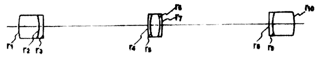
제3도는 본 발명에 관련된 텔레센트릭 결상 광학계의 제1의 실시예를 나타낸 렌즈 구성도.3 is a lens configuration diagram showing a first embodiment of a telecentric imaging optical system according to the present invention.
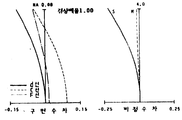
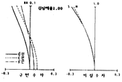
제4a, b, c도는 제1의 실시예에 있어서 결상배율을 변화시킨 경우의 각 수차 곡선도.4A, 4B, and 5C are respective aberration curve diagrams when the imaging magnification is changed in the first embodiment.
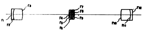
제5도는 본 발명의 제2의 실시예를 나타낸 렌즈 구성도.5 is a lens diagram showing a second embodiment of the present invention.
제6a, b, c도는 제2의 실시예에 있어서 결상배율을 변화시킨 경우의 각 수차 곡선도.6A, 6B and 6C are respective aberration curve diagrams when the imaging magnification is changed in the second embodiment.
제7도는 본 발명의 제3의 실시예를 나타낸 렌즈 구성도.7 is a lens diagram showing a third embodiment of the present invention.
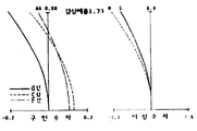
제8a, b, c도는 제3의 실시예에 있어서 결상배율을 변화시킨 경우의 각 수차 곡선도.8A, 8B and 8C are respective aberration curve diagrams when the imaging magnification is changed in the third embodiment.
제9도는 본 발명의 제4의 실시예를 나타낸 렌즈 구성도.9 is a lens block diagram showing a fourth embodiment of the present invention.
제10a, b, c도는 제4의 실시예에 있어서 결상배율을 변화시킨 경우의 각 수차 곡선도.10A, 10B and 10C are respective aberration curve diagrams when the imaging magnification is changed in the fourth embodiment.
제11는 레이저 플롯터 시스템의 외관 사시도.11 is an external perspective view of a laser plotter system.
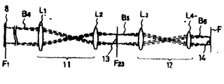
제12도 레이저 플롯터의 노광 헤드의 종래예를 나타낸 사시도.12 is a perspective view showing a conventional example of an exposure head of a laser plotter.
제13a도는 제12도의 노광 헤드의 텔레센트릭 결상 광학계를 발췌하여 나타낸 개략 렌즈 구성도.FIG. 13A is a schematic lens configuration diagram showing an excerpt from the telecentric imaging optical system of the exposure head of FIG. 12; FIG.
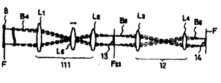
제13b, c, d도는 각각 본 발명의 적용예를 나타낸 렌즈 구성의 설명도.13B, c, and D are explanatory diagrams of a lens configuration each showing an application example of the present invention.
* 도면의 주요 부분에 대한 부호의 설명* Explanation of symbols for the main parts of the drawings
S : 서짓탈 상면 M : 메리디오널 상면S: Upper surface of Seottal M: Upper surface of Meridional
본 발명은 주광선이 광축과 평행으로 입출사하는 텔레센트릭(Telecentric) 결상 광학계에 관한 것으로, 특히 결상배율을 변경할 수 있는 텔레센트릭 결상 광학계에 관한 것이다.The present invention relates to a telecentric imaging optical system in which chief ray enters and exits in parallel with an optical axis, and more particularly, to a telecentric imaging optical system capable of changing the imaging magnification.
본 발명은 투영 검사기나, 광학 측정기에 이용할 수 있으며, 또한 광의의 노광장치나, 협의의 노광장치 예컨대 칼라 스캐너(Colour Scanner) 또는 레이저 플롯터(Laser Plotter) 등의 레이저 노광장치의 결상 광학계에 이용할 수 있는 것이다.INDUSTRIAL APPLICABILITY The present invention can be used for a projection inspector or an optical measuring device, and can be used for an optical exposure system of a wide range of exposure apparatuses, or an imaging optical system of a laser exposure apparatus such as a color scanner or a laser plotter. It can be.
정의 초점거리를 갖는 대물 렌즈의 후측 초점과, 동일하게 정의 초점거리를 갖는 접안렌즈의 전축 초점을 일치시킨 렌즈계는 망원경계로서 종래부터 이미 공지되어 있는 것이었다.A lens system in which the rear focal point of an objective lens having a positive focal length and the front axis focus of an eyepiece lens having a positive focal length are equally matched has been known in the past as a telescope system.
이 망원경계의 대물렌즈의 전측 초점근방에 물체를 위치시킨 경우 접안렌즈의 후측 초점근방에 도립실상이 형성되고, 주광선이 광축과 평행으로 일출사하는 텔레센트릭 결상 광학계로 된다.When an object is positioned near the front focal point of the objective lens of this telescope system, an inverted real image is formed near the rear focal point of the eyepiece, and a telecentric imaging optical system is formed in which the main rays of light rise and fall parallel to the optical axis.
이 경우, 형성되는 실상의 물체에 대한 배율은 접안렌즈의 초점거리와 대물렌즈의 초점거리와의 비로 되고, 물체거리를 변화시켜도 결상배율이 변화하지 않는 특성이 있다.In this case, the magnification of the actual object to be formed is a ratio between the focal length of the eyepiece and the focal length of the objective lens, and the imaging magnification does not change even if the object distance is changed.
이 특성을 이용하여 텔레센트릭 결상 광학계는 예컨대 일본국 특허공개 소51-96336호 공보에 개시된 바와 같이 치수정도가 정밀한 측정기의 광학계에서 이용하는 경우가 많은 것이다.By using this characteristic, the telecentric imaging optical system is often used in an optical system of a measuring device with precise dimensional accuracy as disclosed in, for example, Japanese Patent Application Laid-open No. 51-96336.
또한, 주광선이 광축과 평행으로 입출사하는 특성을 이용하여 전치렌즈계에 의하여 한번 결상된 공중상을 후치 렌즈계의 물체로서 그 상을 재차 작성하는 릴레이 렌즈로서도 이용되고 있다.Moreover, it is used also as a relay lens which regenerates the aerial image formed by the pre-lens system once again as an object of a post-lens system using the characteristic which a chief ray enters and exits in parallel with an optical axis.
예컨대, 미국 특허출원번호 제33,582호에는 레이저 노광장치, 특히 레이저 플롯터의 결상 광학계에 2단의 텔레센트릭 광학계를 이용한 기술이 개시되어 있다.For example, US Patent Application No. 33,582 discloses a technique using two-stage telecentric optics for an imaging optical system of a laser exposure apparatus, in particular a laser plotter.
이와 같은 텔레센트릭 결상 광학계의 결상배율은 물체거리 및 상거리를 변경하여도 항시 일정하게 유지되고, 사용하는 렌즈의 초점거리의 조합에 의해서만 결정되어 진다.The imaging magnification of the telecentric imaging optical system is always kept constant even when the object distance and the image distance are changed, and are determined only by the combination of the focal lengths of the lenses used.
따라서, 설계된 렌즈 내지 렌즈군에 가공오차가 있다든지, 조립시의 배열이나 조정에 오차가 있다든지 하여 설계시에 결정된 결상배율과는 상이한 배율로 되는 경우, 종래에는 이것을 설계를 통하여 수정하는 것은 곤란한 것이었다.Therefore, if the designed lens or lens group has a processing error, an error in the arrangement or adjustment during assembly, or a magnification different from the imaging magnification determined at the time of design, it is difficult to correct this through the design. Was.
또한, 종래의 텔레센트릭 결상 광학계에 있어서는 물상간 거리를 일정하게 유지함과 동시에 주광선이 광축과 평행으로 입출사하는 상태를 유지한 채로 결상의 성능을 양호한 일정수준 이상으로 유지시켜서 변배비를 2배이상으로 변경시키는 것은 매우 곤란한 것이었다.In addition, in the conventional telecentric imaging optical system, the distance between objects is kept constant, and the imaging performance is maintained at a good level or more while maintaining the state where the chief ray enters and exits in parallel with the optical axis. It was very difficult to change the above.
그러나, 종래에 있어서도 변배비를 1.5나 1.8 또는 높게는 2배까지 가능하게 되지만(상기 미국특허출원에 개시), 예컨대 레이저 플롯터에 있어서 완성품의 정도의 조밀에 의하여 인화정도를 2배이상으로 바꾸면 아트워크를 특단으로 효율좋게 진행시킬 수 있기 때문에, 이전부터 결상성능을 열화시킴이 없이 2배이상의 변배비를 갖는 텔레센트릭 결상 광학계가 요망되어 왔었다.However, even in the related art, the variation ratio can be 1.5 or 1.8 or twice as high (as disclosed in the above-mentioned US patent application). However, if the degree of printing is changed to 2 times or more due to the density of the finished product, for example, in a laser plotter. Since the artwork can be efficiently and efficiently progressed, a telecentric imaging optical system having a variable magnification of more than two times has been desired without deteriorating the imaging performance.
본 발명은 이와 같은 문제점을 해결하기 위하여 첫째로 렌즈의 가공오차등을 보상할 수 있도록 결상배율의 수정이 가능한 텔레센트릭 결상 광학계를 제공하는 것을 목적으로 하고, 또한 둘째로는 결상배율의 수정을 포함하고 결상성능을 2배 이상의 변배가 가능한 텔레센트릭 결상 광학계를 제공하는 것을 목적으로 하는 것이다.The present invention aims to provide a telecentric imaging optical system capable of correcting an imaging magnification so as to compensate for processing errors in a lens, and secondly, to solve such problems. It is an object of the present invention to provide a telecentric imaging optical system that includes and can double the imaging performance.
이러한 목적을 달성하기 위하여 본 발명은 기본적으로 이하와 같이 구성된 것이다.In order to achieve this object, the present invention is basically configured as follows.
즉, 물체측으로부터 순차적으로 정의 초점거리 f1을 갖는 제1군의 렌즈와, 정의 초점거리 f2를 갖는 제2군의 렌즈와, 정의 초점거리 f3을 갖는 제3군의 렌즈를 배열한 렌즈계에 있어서, 상기 제1군의 렌즈의 후측 초점에 그 전측 초점을 거의 일치하도록 상기 제3군 렌즈를 배치하고, 상기 제2군 렌즈를 적어도 f1/2<f2또한 f3/2<f2의 관계를 만족하는 초점거리로 설정함과 동시에 광축에 연하여 이동가능하게 하고, 상기 양 초점을 거의 일치시킨 위치의 근방에 배치하여 구성되며, 물상간 거리를 거의 일정하게 유지하면서 주로 상기 제2군 렌즈를 광축에 연하여 이동시키는 것에 의하여 결상배율을 변경할 수 있도록 된 변배가능한 텔레센트릭 결상 광학계인 것이다.That is, the first group of lenses having the positive focal length f 1 , the second group of lenses having the positive focal length f 2 , and the third group of lenses having the positive focal length f 3 are sequentially arranged from the object side. in the lens system, wherein the placing the third group lens to closely match the anterior focus on the rear focal point of the lens of the first group and the second group lens at least a f 1/2 <f 2 also f 3/2 < A focal length that satisfies the relationship of f 2 , and is set to be movable along the optical axis, and is arranged near the position where both the foci are substantially coincident with each other. It is a variable telecentric imaging optical system that can change the imaging magnification by moving the second group lens along the optical axis.
제2군 렌즈를 이동하면, 제1군 및 제2군 렌즈의 합성 초점위치가 변동된다. 텔레센트릭 광학계의 특성을 유지하기 위하여서는 그 변동량에 따라서 제3군 렌즈를 이동시켜서 그 전측 초점위치를 상기 합성 초점 위치에 일치시킬 필요가 있다.When the second group lens is moved, the combined focus positions of the first group and the second group lenses are changed. In order to maintain the characteristics of the telecentric optical system, it is necessary to move the third group lens in accordance with the amount of variation so that the front focal position matches the composite focal position.
그러나, 3군의 렌즈의 각각의 초점거리를 적절하게 선택하는 것에 의하여 제2군 렌즈의 이동량이 적은 경우에는 제1군 및 제2군 렌즈의 합성 초점위치의 변동량을 극히 미량으로 유지할 수 있어서 제3군 렌즈를 이동시킴이 없이 고정함에 있어서도 거의 텔레센트릭 광학계를 유지할 수가 있게 되는 것이다.However, by appropriately selecting the focal lengths of the three groups of lenses, when the amount of movement of the second group of lenses is small, the amount of variation in the combined focus positions of the first and second group of lenses can be kept to a very small amount. It is possible to maintain almost telecentric optics even when the group 3 lens is fixed without moving.
또한, 변배비를 2배이상 크게 변화시키기 위하여서는 제2군 렌즈의 이동을 크게할 필요가 있게 된다. 따라서, 적어도 제3군 렌즈를 광축에 연하여 이동가능하게 함과 동시에 제2군 렌즈의 초점거리 f2를 f2<2f1또한 f2<2f3의 관계를 제2군 관계를 만족하도록 하고, 상기 제2군 렌즈의 이동에 수난하여 이동하는 제1군 및 제2군 렌즈의 합성 후측 초점위치에 그 전측 초점이 항시 일치하도록 상기 제3군 렌즈를 이동시킨다.In addition, it is necessary to increase the movement of the second group lens in order to change the variable ratio more than twice. Therefore, at least the third group lens can be moved along the optical axis, and the focal length f 2 of the second group lens is f 2 <2f 1 and f 2 <2f 3 so as to satisfy the second group relationship. The third group lens is moved so that the front focal point always coincides with the combined rear focus position of the first group and the second group lenses which move in difficulty due to the movement of the second group lens.
이렇게 하여서 완전한 텔레센트릭 결상 광학계로 되기 때문에 이 경우 물체거리를 변경시켜도 결상배율은 변화하지 않는다.In this case, since it becomes a complete telecentric imaging optical system, the imaging magnification does not change even if the object distance is changed.
그러나, 물체거리를 변경시키면, 그 상위치도 변화하게 되어서, 각 배율에 따라서 물체거리를 적당하게 선택하면 결상배율이 어떻게 되든지는 구애받지 않고 물체와 상간격을 일정하게 유지할 수가 있다.However, if the object distance is changed, the upper value is also changed. If the object distance is appropriately selected according to each magnification, the object and the phase interval can be kept constant regardless of the imaging magnification.
이 경우 물체위치를 기준으로 하고, 또한 제1군 렌즈를 이동 가능하게 하면, 상위치는 변화하지 않고 완전한 텔레센트릭 줌 결상 광학계로 된다. 또한, 상위치를 기준으로 하는 경우, 제1군 렌즈는 반드시 이동 가능하게 할 필요가 없고, 이 광학계 전체를 광축에 연하여 이동가능하도록 구성하면 되는 것이다.In this case, if the first group lens is made movable based on the object position, the upper level value does not change and becomes a complete telecentric zoom imaging optical system. In the case where the difference value is used as a reference, the first group lens does not necessarily need to be movable, and the whole optical system may be configured to be movable in connection with the optical axis.
본 발명에 연관된 렌즈계는 실물체, 상율 대상으로 하는 결상 광학계인 것이어서 물체 및 상은 광학계의 외측, 즉 물체가 제1군 렌즈의 전방으로 위치됨과 동시에 상이 제3군 렌즈의 후방으로 존재하기 않으면 안되는 것이다.The lens system related to the present invention is a real object, an imaging optical system targeted for an image rate, so that an object and an image must be outside of the optical system, that is, the object is positioned in front of the first group lens and the image must be present behind the third group lens. .
따라서, 각군 렌즈의 초점거리 f1,f2,f3는 적어도 f1/2<f2또한 f3/2<f2의 조건을 만족시킬 필요가 있게 된다. 또한, f1,f3와 비교하여 f2의 값을 적게하면, 상면만곡이 크게 되어 유효화면 치수를 크게할 수 없게 된다.Thus, the focal length of each group lens f 1, f 2, f 3 is it is necessary to satisfy the condition of at least f 1/2 <f 2 also f 3/2 <f 2. In addition, if the value of f 2 is reduced in comparison with f 1 and f 3 , the upper surface curvature becomes larger and the effective screen size cannot be increased.
상면의 평탄성을 양호하게 함과 동시에 유효화면 치수를 크게하기 위하여서는 f2를 크게하는 것이 바람직스러운 것이다.It is desirable to increase f 2 in order to improve the flatness of the upper surface and to increase the effective screen size.
그러나, 반대로 f2가 f1및 f3와 비교하여 너무 크게하면, 제2군 렌즈를 제1군 렌즈와 제3군 렌즈의 간격으로 최대로 이동시켜도 결상배율이 그다지 변화하지 않는다.On the contrary, if f 2 is too large in comparison with f 1 and f 3 , the imaging magnification does not change much even when the second group lens is moved to the maximum at the interval between the first group lens and the third group lens.
따라서, 수차와 화면치수를 고려하여 변배비를 2배이상으로 하기 위하여서는 f2를 크게 하여도 f2<2f1또한 f2<2f3의 조건정도로 한정시킬 필요가 있는 것이다. 이것에 대하여, 2배이상의 변배비를 실현하기 위하여서는 f1/2<f2<2f1또한 f3/2<f2<2f3의 조건을 만족시킬 필요가 있다.Therefore, there is a In order to change the baebi in consideration of aberration and the screen size of 2 times or more and is necessary to limit extent of the condition by increasing the degree f 2 f 2 <2f 1 f 2 also <2f 3. On the other hand, In order to realize the service baebi two or more times, it is necessary to satisfy the condition of f 1/2 <f 2 < 2f 1 also f 3/2 <f 2 < 2f 3.
더욱이, 결상배율의 미조정만을 목정으로 하는 경우에는 f2<2f1또한 f2<2f3의 조건은 필요하지 않게 된다.In addition, in the case where only fine adjustment of the imaging magnification is to be observed, the conditions of f 2 <2f 1 and f 2 <2f 3 are not necessary.
본 발명은 결과로서 보면, 제1군 렌즈와 제3군 렌즈로 된 텔레센트릭 광학계에 제2군 렌즈를 삽입한 것으로 보이지만, 이러한 것이 아니고, 물체위치와 상위치가 고정되어 있고 이 사이에 각각 정의 초점거리를 갖는 3개의 렌즈군으로 된 렌즈계를 설계, 배치하여 상술한 문제점을 해결하도록 하는 것에 특징이 있는 것이다.As a result, the present invention appears to have inserted the second group lens into the telecentric optical system consisting of the first group lens and the third group lens, but this is not the case, and the object position and the upper value are fixed, respectively. The above-described problem is characterized by designing and arranging a lens system of three lens groups having a positive focal length.
[실시예]EXAMPLE
제1도는 본 발명에 연관된 텔레센트릭 결상 광학계의 원리를 설명하기 위한 개략도이며, 여기서는 설명을 간단하게 하기 위하여 단렌즈를 사용하였다.1 is a schematic diagram for explaining the principle of the telecentric imaging optical system according to the present invention, in which a single lens is used to simplify the description.
도시한 바과 같이, 제1,2,3렌즈의 초점거리를 각각 100, 각 렌즈간격을 각각 100으로 하고, 제1렌즈의 전방 50에 물체를 놓을 경우를 상정하면, 제3렌즈의 후방 50의 위치에 상이 결상되고 그 결상배율은 1이 된다. 지금, 제1도에서 점선으로 나타낸 바와 같이 제2렌즈를 광축상에서 후방(제3렌즈의 방향)으로 10이동시킨 경우, 제1 및 제2렌즈의 합성 후측 초점위치는 제1렌즈측으로 1.1만큼 이동한다.As shown, assuming that the focal lengths of the first, second, and third lenses are 100 and each lens interval is 100, and the object is placed in front of the first lens, the rear 50 of the third lens The image is lost at the position, and the magnification is 1. Now, as shown by the dotted line in FIG. 1, when the second lens is moved 10 backwards on the optical axis (the direction of the third lens), the combined rear focus position of the first and second lenses is shifted by 1.1 toward the first lens side. do.
따라서, 완전한 텔레센트릭 광학계를 유지하기 위하여서는 제3렌즈를 전방으로 1.1이동시킬 필요가 있지만, 그 이동량은 제3렌즈의 초점거리와 비교하면 겨우 1% 정도에 지나지 않기 때문에 제3렌즈를 고정된 그대로의 상태에서도 실용상 텔레센트릭 광학계로 생각하여도 별지장이 생기지 않는 것이다. 또한, 이 경우 물체의 위치가 동일한 위치로 하면 상위치의 변화는 +0.226으로 되지만, 이 값은 렌즈의 수차량과 거의 같은 정도의 것이어서 렌즈의 밝기에는 약간 관계가 있지만, 무시할 수 있는 수치인 것이다. 또한, 이 경우 제1 및 제2렌즈의 합성 초점거리를 111.1로 되고 결상배율은 0.9로 된다.Therefore, in order to maintain a complete telecentric optical system, it is necessary to move the third lens forward 1.1, but since the amount of movement is only about 1% compared to the focal length of the third lens, the third lens is fixed. Even in the state as it is, even if it is considered to be a telecentric optical system for practical use, it does not cause any trouble. In this case, if the position of the object is the same position, the change of the upper value becomes +0.226, but this value is almost the same as the amount of aberration of the lens, which is slightly related to the brightness of the lens, but it is a negligible value. . In this case, the combined focal length of the first and second lenses is 111.1, and the imaging magnification is 0.9.
역으로, 제2렌즈를 광축상으로 제1도에서 실선의 위치에서 전방(제1렌즈의 방향)으로 10이동시킨 경우, 제1 및 제2렌즈의 합성 초점거리는 90.909로 되고 결상배율은 1.1로 되며, 제2렌즈의 전후 10의 이동에서 1.22의 배율변화가 가능하게 된다.Conversely, if the second lens is moved ten times forward from the position of the solid line on the optical axis (in the direction of the first lens) on the optical axis, the combined focal length of the first and second lenses is 90.909 and the imaging magnification is 1.1. In this case, a magnification change of 1.22 is possible in the movement of 10 before and after the second lens.
상기한 원리설명에서는 도시, 설명을 간단하게 하기 위하여 제1,제2,제3의 각 렌즈를 얇은 단렌즈로 한 것이지만, 실제서는 각각 복수매의 렌즈로서 제1군렌즈, 제2군렌즈, 제3군렌즈로서 구성되기 때문에 주점을 고려할 필요가 있다.In the above-described principle description, for the sake of simplicity of illustration and description, each of the first, second, and third lenses is formed as a thin single lens, but in practice, a plurality of lenses are used as the first group lens, the second group lens, Since it is comprised as a 3rd group lens, it needs to consider a principal point.
또한, 제1군렌즈(각 주점:H11,H12) 및 제3군렌즈(각 주점:H31,H32)가 각각 구면수차를 갖고 있는 경우에는 광축으로 평행하게 입사된 광선이 초점위치를 통과하지 않기 때문에 제2도에 나타낸 바와 같이, 초점위치에 구면수차량 △S(△S1,△S2)를 가산된 위치를 제2군렌즈의 각 주점 H21,H22와 일치시킬 필요가 있다.Further, when the first group lens (each pub: H 11 , H 12 ) and the third group lens (each pub: H 31 , H 32 ) each have spherical aberration, the light rays incident in parallel to the optical axis are focused. As shown in FIG. 2, the position where the spherical aberration amount ΔS (ΔS 1 , ΔS 2 ) is added to the focal point is matched with the respective main points H 21 , H 22 of the second group lens as shown in FIG. 2. There is a need.
또한, 구면수차량 △S의 값은 제1군 및 제3군 렌즈의 구성에 의하여 정(正)으로 된 경우와 부(負)로 된 경우가 있다.In addition, the value of the spherical aberration amount ΔS may be positive or negative depending on the configuration of the first group and the third group lenses.
이하에 나타낸 실시예는 모두 제2군렌즈의 주점격차를 고려한 것으로, 상기 구면수차를 포함한 텔레센트릭 결상 광학계로 된 것이다.The examples shown below all consider the main point difference of the second group lens, and constitute a telecentric imaging optical system including the spherical aberration.
[실시예 1]Example 1
제1의 실시예는 상기한 결상배율의 수정을 가능하게 된 텔레센트릭 결상 광학계의 일예를 나타낸 것으로, 제3도에 나타낸 각군 렌즈로서의 이하의 것을 사용한다.The first embodiment shows an example of a telecentric imaging optical system that enables the correction of the imaging magnification described above, and uses the following as the lens for each group shown in FIG.
제1군First group
r1: 42.40r 1 : 42.40
d1: 16.0 n1: 1.564 υ1: 60.8d 1 : 16.0 n 1 : 1.564 υ 1 : 60.8
r2: -24.80r 2 : -24.80
d2: 3.2 n2: 1.744 υ2: 45.1d 2 : 3.2 n 2 : 1.744 υ 2 : 45.1
r3: -232.00r 3 : -232.00
d3: 가변d 3 : variable
제2군2nd group
r4: 92.80r 4 : 92.80
d4: 1.6 n4: 1.670 υ4: 47.1d 4 : 1.6 n 4 : 1.670 υ 4 : 47.1
r5: 24.80r 5 : 24.80
d5: 8.0 n5: 1.623 υ5: 58.2d 5 : 8.0 n 5 : 1.623 υ 5 : 58.2
r6: -24.8r 6 : -24.8
d6: 1.6 n6: 1.670 υ6: 47.1d 6 : 1.6 n 6 : 1.670 υ 6 : 47.1
r7: -92.80r 7 : -92.80
d7: 가변d 7 : variable
제3군3rd group
r8: 232.00r 8 : 232.00
d8: 3.2 n8: 1.744 υ8: 45.1d 8 : 3.2 n 8 : 1.744 υ 8 : 45.1
r9: 24.80r 9 : 24.80
d9: 16.0 n9: 1.564 υ9: 60.8d 9 : 16.0 n 9 : 1.564 υ 9 : 60.8
r10: -42.40r 10 : -42.40
f1: 102.55 f2: 95.61 f3: 102.55f 1 : 102.55 f 2 : 95.61 f 3 : 102.55
NA : 0.068NA: 0.068
화면치수 : 9![]()
![]()
기준배율(1.00)에 있어서의 물체와 상간의 거리 : 319.52Distance between object and phase at standard magnification (1.00): 319.52
본 실시예에 있어서의 각 결상배율 1.11, 1.00, 0.90에 대응하는 각 렌즈배치는 이하와 같다.Each lens arrangement corresponding to each of the image forming magnifications 1.11, 1.00, and 0.90 in the present embodiment is as follows.
d0d3d7d10배율d 0 d 3 d 7 d 10 Magnification
51.16 73.8 93.8 51.49 1.1151.16 73.8 93.8 51.49 1.11
51.16 83.8 83.8 51.16 1.0051.16 83.8 83.8 51.16 1.00
51.16 93.8 73.8 51.43 0.9051.16 93.8 73.8 51.43 0.90
단, r1,r2,....는 렌즈 각면의 곡율반경, d1,d2,d4,d5,d6,d8,d9는 각 렌즈의 중심두께, n1,n2,...는 각 렌즈엘레멘트의 파장 587.6nm로의 광에 대한 굴정율, v1,v2,...는 각 렌즈엘레멘트의 압배 수(Abbe Number), f1,f2,f3는 렌즈군의 합성초점 거리이며, d0는 물체와 곡율 r1면과의 거리, d3는 곡율 r3면과 곡율 r4면과의 거리, d7은 곡율 r7면과 곡율 r8면과의 거리, d10은 곡율 r10면과 상면과의 거리이다.Where r 1 , r 2 , .... is the radius of curvature of each side of the lens, d 1 , d 2 , d 4 , d 5 , d 6 , d 8 , d 9 is the center thickness of each lens, n 1 , n 2 , ... is the refractive index for the light of wavelength 587.6nm of each lens element, v 1 , v 2 , ... is the Abbe Number of each lens element, f 1 , f 2 , f 3 is the combined focal length of the lens, d 0 is the distance to the object and the curvature r 1 side, d 3 is the curvature r 3 if the curvature r is the distance to page 4, d 7 is a curvature r 7 side and the curvature r 8 surfaces, and D 10 is the distance between the curvature r 10 plane and the top plane.
또한, 제4도 (a),(b),(c)는 제1의 실시예에 있어서의 제2군 렌즈를 기준배율 1.00의 경우와 전후로 10이동시켜서 결상배율이 각각 1.11, 0.90으로 된 경우에 있어서의 구면수차와 비점수차를 나타낸 수차곡선도이다. 원점은 어느 것이든 상기한 상거리 d10의 지점에서 취한 것이다.4 (a), 4 (b), and (c) show that the imaging magnification becomes 1.11 and 0.90, respectively, by moving the second group lens in the first embodiment forward and backward 10 times in the case of the reference magnification 1.00. Aberration curve diagram showing spherical and astigmatism in. The origin is taken at the point of the above-mentioned distance d 10 .
본 실시예에서 상거리 d10은 51.56으로 고정시켜도 실용상 어떠한 지장이 없는 것이다.In this embodiment, even if the distance d 10 is fixed at 51.56, there is no practical problem.
또한, 제3군 렌즈를 미소량만큼 변위시키고, 상면을 극미소량만 이동시키는 것이 바람직스러운 것이다.It is also preferable to displace the third group lens by a small amount and to move only a very small amount of the image surface.
[실시예 2]Example 2
제5도에 나타낸 제2의 실시예는 렌즈제가 밝으며, 텔레센트릭 특성, 초점이동이 문제가 되는 경우를 고려한 것으로, 이 제2군 렌즈를 2군으로 분리가능하게 구성하여 제2군 렌즈의 이동에 수반하여 그 간격을 변화시키면 물체 및 제1군 렌즈, 제3군 렌즈를 고정시킨채로 텔레센트릭 특성이 유지되고, 또한 상위치의 변화를 없게 할 수 있는 일예를 나타낸 것이다.The second embodiment shown in FIG. 5 considers the case where the lens is bright, and the telecentric characteristic and the focus shift are a problem, and the second group lens is separable into two groups so that the second group lens can be separated. When the distance is changed in accordance with the movement of, the telecentric characteristic is maintained while the object, the first group lens, and the third group lens are fixed, and an example is shown in which the difference of the upper value can be prevented.
제1군First group
r1: 1180.00r 1 : 1180.00
d1: 4.0 n1: 1.728 υ1: 28.3d 1 : 4.0 n 1 : 1.728 υ 1 : 28.3
r2: 38.30r 2 : 38.30
d2: 20.0 n2: 1.670 υ2: 47.1d 2 : 20.0 n 2 : 1.670 υ 2 : 47.1
r3: -64.00r 3 : -64.00
d3: 가변d 3 : variable
제2군2nd group
r4: 115.00r 4 : 115.00
d4: 2.0 n4: 1.670 υ4: 40.4d 4 : 2.0 n 4 : 1.670 υ 4 : 40.4
r5: 37.80r 5 : 37.80
d5: 3.0 n5: 1.569 υ5: 56.0d 5 : 3.0 n 5 : 1.569 υ 5 : 56.0
r6: ∞r 6 : ∞
d6: 가변d 6 : variable
r7: ∞r 7 : ∞
d7: 3.0 n7: 1.569 υ7: 56.0d 7 : 3.0 n 7 : 1.569 υ 7 : 56.0
r8: -37.8r 8 : -37.8
d8: 2.0 n8: 1.607 υ8: 40.4d 8 : 2.0 n 8 : 1.607 υ 8 : 40.4
r9: -115.00r 9 : -115.00
d9: 가변d 9 : variable
제3군3rd group
r10: 64.00r 10 : 64.00
d10: 20.0 d10: 1.607 d10: 47.1d 10 : 20.0 d 10 : 1.607 d 10 : 47.1
r11: -38.00r 11 : -38.00
d11: 4.0 n11: 1.728 υ11: 28.3d 11 : 4.0 n 11 : 1.728 υ 11 : 28.3
d11: 4.0 n11: 1.728 υ11: 28.3d 11 : 4.0 n 11 : 1.728 υ 11 : 28.3
r12: -1180.00r 12 : -1180.00
(d12)(d 12 )
f1: 103.56f 1 : 103.56
f2(기준배율 1.00에 있어서) : 119.10f 2 (at standard magnification 1.00): 119.10
f3: 103.56f 3 : 103.56
NA : 0.08NA: 0.08
화면치수 : 12![]()
![]()
물상간거리 : 346.20Distance between water phases: 346.20
본 실시예에 있어서의 각 결상배율 1.11, 1.00, 0.90에 대응하는 각 렌즈배치는 이하와 같다.Each lens arrangement corresponding to each of the image forming magnifications 1.11, 1.00, and 0.90 in the present embodiment is as follows.
d0d2d6d9d12비율d 0 d 2 d 6 d 9 d 12 Ratio
43.50 89.1 0.1 112.0 43.50 1.1143.50 89.1 0.1 112.0 43.50 1.11
43.50 100.0 1.2 100.0 43.50 1.0043.50 100.0 1.2 100.0 43.50 1.00
43.56 112.0 0.1 89.1 43.50 0.9143.56 112.0 0.1 89.1 43.50 0.91
단, d0는 물체와 곡율, r1면과의 거리, d3는 곡율 r3면과 곡율 r4면과의 거리, d6은 곡율 r6면과 곡율 r7면과의 거리, d9은 곡율 r9면과 곡율 r10면과의 거리, d12는 곡율 r12면과 상면까지의 거리를 나타낸 것이다.Where d 0 is the distance between the object and curvature, r 1 , d 3 is the distance between curvature r 3 and curvature r 4 , d 6 is the distance between curvature r 6 and curvature r 7 , and d 9 Is the distance between the curvature r 9 plane and the curvature r 10 plane, and d 12 is the distance from the curvature r 12 plane to the top plane.
또한, 제6도 (a),(b),(c)는 제2군 렌즈의 이동에 수반되어 상기 제2군 렌즈의 곡율면 r6,r7사이의 간격을 변화시킬 시에 얻어진 경상 배율이 각각 1.00, 1.11, 0.90으로 된 경우에 있어서의 구면수차와 비점수차를 나타낸 수차곡선도이다.6 (a), 6 (b) and 6 (c) are ordinary magnifications obtained when the interval between the curvature surfaces r 6 and r 7 of the second group lens is changed with the movement of the second group lens. These are aberration curve diagrams showing spherical aberration and astigmatism when 1.00, 1.11, and 0.90 are obtained, respectively.
본 실시예에 의하면, 제2군 렌즈를 분리가능하게 된 것이어서 제3군 렌즈를 고정시킨 채로 상거리 d12를 고정시킬 수 있다.According to this embodiment, since the second group lens is detachable, the image distance d 12 can be fixed while the third group lens is fixed.
또한, 상기 제1 및 제2의 실시예에 있어서, 광이 우측에서 좌측으로 진행한다고 생각한다면, 상거리는 물체거리 그대로 적용할 수가 있다.In the first and second embodiments, if the light travels from right to left, the image distance can be applied as it is.
[실시예 3]Example 3
제7도에 나타낸 제3의 실시예는 텔레센트릭 결상 광학계에 있어서의 결상배율을 크게 변화시키기 위하여 제2군 렌즈의 이동량을 크게한 경우에 관한 것으로, 이 경우에는 제1군 렌즈 및 제2군 렌즈의 합성 초점위치의 변화도 크게되기 때문에 이 합성 초점위치의 이동에 따라서 제3군 렌즈를 이동시켜 제3군 렌즈의 전측 초점위치를 상기 합성 초점위치로 일치시켜서 구성된 것이다.The third embodiment shown in FIG. 7 relates to a case in which the movement amount of the second group lens is increased in order to greatly change the imaging magnification in the telecentric imaging optical system. In this case, the first group lens and the second group Since the change in the combined focus position of the group lens is also large, the third group lens is moved in accordance with the shift of the combined focus position, and the front focus position of the third group lens is matched with the combined focus position.
이 경우, 완전한 텔레센트릭 결상 광학계로 되기 위하여 물체거리를 변화시켜도 일단 설정된 결상배율은 변화하지 않는 특징을 가진 것이다.In this case, even if the object distance is changed to become a complete telecentric imaging optical system, the set imaging magnification does not change.
제1군First group
r1: 1180.00r 1 : 1180.00
d1: 4.0 n1: 1.728 υ1: 28.3d 1 : 4.0 n 1 : 1.728 υ 1 : 28.3
r2: 38.30r 2 : 38.30
d2: 20.0 n2: 1.670 υ2: 47.1d 2 : 20.0 n 2 : 1.670 υ 2 : 47.1
r3: -64.00r 3 : -64.00
d3: 가변d 3 : variable
제2군2nd group
r4: 115.00r 4 : 115.00
d4: 2.0 n4: 1.670 υ4: 40.4d 4 : 2.0 n 4 : 1.670 υ 4 : 40.4
r5: 37.80r 5 : 37.80
d5: 10.0 n5: 1.569 υ5: 56.0d 5 : 10.0 n 5 : 1.569 υ 5 : 56.0
r6: -37.80r 6 : -37.80
d6: 2.0 n6: 1.607 υ6: 40.4d 6 : 2.0 n 6 : 1.607 υ 6 : 40.4
r7: -115.00r 7 : -115.00
d7: 가변d 7 : variable
제3군3rd group
r8: 64.00r 8 : 64.00
d8: 20.0 n8: 1.607 υ8: 47.1d 8 : 20.0 n 8 : 1.607 υ 8 : 47.1
r9: -38.00r 9 : -38.00
d9: 4.0 n9: 1.728 υ9: 28.3d 9 : 4.0 n 9 : 1.728 υ 9 : 28.3
r10: -1180.00r 10 : -1180.00
f1: 103.56 f2: 119.45 f3: 103.56f 1 : 103.56 f 2 : 119.45 f 3 : 103.56
NA : 0.08NA: 0.08
화면치수 : 8![]()
![]()
물체 상간의 거리 : 345.74Distance between objects: 345.74
본 실시예에 있어서의 각 결상배율 1.73, 1.00, 0.58에 대응하는 각 렌즈배치는 이하와 같다.The lens arrangements corresponding to the respective imaging magnifications 1.73, 1.00, and 0.58 in this embodiment are as follows.
d0d3d7d10배율d 0 d 3 d 7 d 10 Magnification
37.50 13.0 148.0 85.25 1.7337.50 13.0 148.0 85.25 1.73
43.87 98.0 98.0 43.87 1.0043.87 98.0 98.0 43.87 1.00
85.25 148.0 13.0 37.50 0.5885.25 148.0 13.0 37.50 0.58
단, d0는 물체와 곡율 r1면과의 거리, d3는 곡율 r3면과 곡율 r4면과의 거리, d7은 곡율 r7면과 곡율 r8면과의 거리, d10은 곡율 r10면과 상면과의 거리를 나타낸 것이다.Where d 0 is the distance between the object and curvature r 1 , d 3 is the distance between curvature r 3 and curvature r 4 , d 7 is the distance between curvature r 7 and curvature r 8 , and d 10 is Curvature r 10 Shows the distance between the top and top surfaces.
또한, 제8도 (a),(b),(c)는 결상 배율이 각각 1.11, 1.73, 0.58인 경우에 있어서의 구면수차와 비점수차를 나타낸 수차곡선도이다.8A, 8B, and 8C are aberration curve diagrams showing spherical and astigmatism when the imaging magnifications are 1.11, 1.73, and 0.58, respectively.
본 실시예에 있어서 결상의 배율비는 상기의 값에 의하면 1.73/0.58 즉, 2.98로 되어 결상의 성능을 열화시킴이 없이 2배 이상의 변배가 가능하게 되는 것이다.In the present embodiment, the magnification ratio of the imaging is 1.73 / 0.58, that is, 2.98, which means that the magnification ratio of two times or more can be changed without degrading the performance of the imaging.
[실시예 4]Example 4
제9도에 나타낸 제4의 실시예는 제3의 실시예와 동일하게 비교적 큰 결상배율의 변화를 가능하게 된 텔레센트릭 결상 광학계로서 제1군 및 제3군 렌즈를 각각 3장으로 구성된 것이다.The fourth embodiment shown in FIG. 9 is a telecentric imaging optical system capable of changing a relatively large imaging magnification as in the third embodiment, and is composed of three first and third group lenses, respectively. .
제1군First group
r1: 103.60r 1 : 103.60
d1: 10.0 n1: 1.734 υ1: 51.1d 1 : 10.0 n 1 : 1.734 υ 1 : 51.1
r2: -154.00r 2 : -154.00
d2: 04d 2 : 04
r3: 51.00r 3 : 51.00
d3: 18.0 n3: 1.620 υ3: 49.8d 3 : 18.0 n 3 : 1.620 υ 3 : 49.8
r4: -60.00r 4 : -60.00
d4: 4.0 n4: 1.750 υ4: 35.2d 4 : 4.0 n 4 : 1.750 υ 4 : 35.2
r5: 40.60r 5 : 40.60
d5: 가변d 5 : variable
제2군2nd group
r6: 109.00r 6 : 109.00
d6: 2.0 n6: 1.624 υ6: 47.1d 6 : 2.0 n 6 : 1.624 υ 6 : 47.1
r7: 38.00r 7 : 38.00
d7: 10.0 n7: 1.589 υ7: 61.2d 7 : 10.0 n 7 : 1.589 υ 7 : 61.2
r8: -38.00r 8 : -38.00
d8: 2.0 n8: 1.624 υ8: 47.1d 8 : 2.0 n 8 : 1.624 υ 8 : 47.1
r9: -109.00r 9 : -109.00
d9: 가변d 9 : variable
제3군3rd group
r10: -40.60r 10 : -40.60
d10: 4.0 d10: 1.750 d10: 35.2d 10 : 4.0 d 10 : 1.750 d 10 : 35.2
r11: 60.0r 11 : 60.0
d11: 18.0 n11: 1.620 υ11: 49.8d 11 : 18.0 n 11 : 1.620 υ 11 : 49.8
r12: -15.00r 12 : -15.00
d12: 0.4d 12 : 0.4
r13: 154.00r 13 : 154.00
d13: n13: 1.734 υ13: 51.1d 13 : n 13 : 1.734 υ 13 : 51.1
r14: -103.60r 14 : -103.60
f1: 101.83 f2: 106.13 f3: 101.83f 1 : 101.83 f 2 : 106.13 f 3 : 101.83
NA : 0.1NA: 0.1
화면치수 : 10![]()
![]()
물상간거리 : 361.51Distance between water phases: 361.51
본 실시예에 있어서의 각 결상배율 1.50, 1.00, 0.67에 대응하는 각 렌즈배치는 이하와 같다.Each lens arrangement corresponding to each of the imaging magnifications 1.50, 1.00, and 0.67 in the present embodiment is as follows.
d0d5d9d14비율d 0 d 5 d 9 d 14 ratio
75.97 7.6 96.0 103.14 1.5075.97 7.6 96.0 103.14 1.50
80.55 60.8 60.8 80.55 1.0080.55 60.8 60.8 80.55 1.00
103.14 96.0 7.6 75.97 0.67103.14 96.0 7.6 75.97 0.67
단, d0는 물체와 곡율, r1면과의 거리, d5는 곡율 r5면과 곡율 r6면과의 거리, d9은 곡율 r9면과 곡율 r10면과의 거리, d14은 곡율 r14면과 상면과의 거리를 나타낸 것이다.Where d 0 is the distance between the object and curvature, r 1 , d 5 is the distance between curvature r 5 and curvature r 6 , d 9 is the distance between curvature r 9 and curvature r 10 , and d 14 shows the distance from the upper surface side and the curvature r 14.
또한, 제10도 (a),(b),(c)는 결상 배율이 각각 1.00, 1.50, 0.67인 경우에 있어서의 구면수차와 비점수차를 나타낸 수차곡선도이다.10A, 10B, and 10C are aberration curve diagrams showing spherical aberration and astigmatism when the imaging magnifications are 1.00, 1.50, and 0.67, respectively.
본 실시예에 있어서 상기의 값에 의하면, 변배비는 1.50/0.67 즉, 2.24로 되며, 이 범위에 있어서 결상의 성능을 양호하게 유지한채로 2배 이상의 변배가 가능한 것이다.According to the above-described value in the present embodiment, the variation ratio is 1.50 / 0.67, that is, 2.24. In this range, the variation ratio can be more than doubled while maintaining the performance of the imaging.
이상 설명한 제1-제4의 실시예에 있어서의 광학계에서는 변배광학의 상식에 따라서 각 렌즈군이 색수차가 없이 조합된 렌즈로 되어 있다.In the optical system according to the first to fourth embodiments described above, the lens group is a lens in which each lens group is combined without chromatic aberration in accordance with the common sense of the variable optical.
또한, 레이저 광학계의 릴레이 렌즈로서 사용하는 경우에는 제2군 렌즈는 조합렌즈로 할 필요가 없이 실용상 단렌즈로서도 되며, 이 경우 필요에 따라서 제1군 및 제3군 렌즈와 조합하여 색수차가 없으면 충분한 것이다.In addition, when used as a relay lens of a laser optical system, the second group lens does not need to be a combined lens, but may be a single lens for practical use. In this case, if there is no chromatic aberration in combination with the first group and the third group lenses as necessary, It is enough.
또한, 상기한 실시예에서는 어느 것이든 제1군 렌즈와 제3군 렌즈의 초점거리가 동등한 경우(기준배율이 1.00)에 대해서 기재한 것이지만, 필요에 따라서 변경하는 것이 가능하며, 이 경우에는 기준배율이 1.00이외의 수치로 되는 것을 자명한 것이다.In addition, in the above embodiment, any of the cases where the focal lengths of the first group lens and the third group lens are equal (reference magnification is 1.00) is described, but it is possible to change them as necessary, in which case the reference It is apparent that the magnification becomes a value other than 1.00.
또한, 1.00에서 크게 이탈되면, 코마수차(비대칭 수차)의 보정이 곤란하게 되어서 이 보정이 가능한 범위내에서 선택한다.In addition, if the deviation is large from 1.00, correction of coma aberration (asymmetry aberration) becomes difficult and is selected within a range where this correction is possible.
또한, 상기한 실시예에서는 초점거리 f2를 f1,r3에 근사한 값으로 되며, 그 이유는 f1,f3과 비교하여 f2의 값이 작게되면 상면 만곡이 크게 되어 유효화된 치수를 크게할 수 없는 점이 있으며, 상면의 평탄성을 좋게하고 유효화면 치수를 크게하기 위하여서는 제2군 렌즈의 초점거리 f2를 길게하는 것이 바람직한 것이다.In addition, in the above-described embodiment, the focal length f 2 is approximated to f 1 , r 3. The reason is that when the value of f 2 decreases as compared to f 1 , f 3 , the upper surface curvature becomes larger, so that the effective dimension is obtained. There is a point that cannot be enlarged, and it is desirable to lengthen the focal length f 2 of the second group lens in order to improve the flatness of the image surface and increase the effective screen dimension.
[적용예][Application Example]
다음, 본 발명의 적용예를 노광장치 특히, 레이저 플롯터에 대하여 설명한다.Next, the application example of this invention is demonstrated about exposure apparatus especially a laser plotter.
제11도는 레이저 플롯터 시스템의 외관구성을 나타내고 있다.11 shows an external configuration of the laser plotter system.
이와 같은 시스템은 현재 저밀도에서 고밀도의 프린트 배선판의 포토마스크를 고속과 동시에 고정도로 만드는 아트워크에 많이 이용하고 있는 것이다.Such a system is now widely used for artworks that make photomasks of low density to high density printed wiring boards high speed and high accuracy.
도면에 나타낸 원통 주사형 레이저 플롯터 시스템은 콘솔(21)과, 콘솔(21)이나 자기테이프에 의하여 입력되는 데이터를 처리하는 데이터 프로세서(23)와 처리된 데이터를 신호로 변환시키는 콘버터(22) 및 콘버터(22)에서의 신호에 따라서 실린더(25)상으로 장착된 감광필름상에 화상을 주사기록하는 레코더(24)로 구성된다.The cylindrical scanning laser plotter system shown in the figure has a console 21, a
화상의 주사기록은 제12도에 예시한 바와 같이 노광헤드가 실린더(25)의 회전축과 평행으로 이동하는 것에 의하여 행해진다.The syringe lock of the image is performed by moving the exposure head in parallel with the axis of rotation of the
제12도는 종래의 노광헤드를 나타낸 것이다.12 shows a conventional exposure head.
레이저 광원(1)으로부터 사출된 레이저광 B1은 렌즈(3a)(3b)로 된 비임 엑스팬터(3)에 의하여 비임경이 확장된 비임 B2로 된다.The laser light B 1 emitted from the laser light source 1 becomes the beam B 2 whose beam diameter is expanded by the beam expander 3 made of the
비임 B2는 비임 스프릿터(4)에 의하여 복수본의 비임 B3으로 된다. 비임 B3은 각각 광변조기(7)에 의하여 변조되어 비임정형판(8)를 통과하여 제1미러(9a), 제2미러(9b)에서 반사되어서 결상 광학제(10)로 입사된다.The beam B 2 becomes a plurality of beams B 3 by the beam splitter 4. The beams B 3 are respectively modulated by the optical modulator 7 and passed through the non-temporal plate 8 to be reflected by the first mirror 9a and the second mirror 9b to enter the imaging
결상 광학제(10)는 렌즈 L1과 렌즈 L2로 된 텔레센트릭 광학제(11)과 렌즈 L3과 렌즈 L4로 된 제2의 텔레센트릭 광학제(12)로 구성되어 있다.Forming
제2미러(9b)에서 반사된 비임 B4는 제1의 텔레센트릭 광학계(11)에 의하여 비임 간격이 좁아져 비임 B5로 된다.The beam B 4 reflected from the second mirror 9b is narrowed by the first telecentric
이 비임 B5는 제2의 텔레센트릭 광학계(12)에 의하여 릴레이되어서 비임 B6으로 되어 실린더(25)상의 필름면상에 상(14)으로 결상된다.This beam B 5 is relayed by the second telecentric
제13a도에 이 결상광학계의 직립단면과 함께 광선의 진행형태를 설명적으로 나타내고 있다. 비임 정형판(8)에 대응하는 면(F1)의 물체는 텔레센트릭 광학계(11)에 의하여 사면(F23)상에 상(13)을 만든다.FIG. 13A shows the propagation mode of the light beam along with the upright section of the imaging optical system. The object on the surface F 1 corresponding to the beam shaping plate 8 makes an
상(13)은 지금 물체로서 제2의 텔레센트릭 광학계(12)에 의하여 릴레이되어서 그 상면(F)상에 상(14)을 맺는다.The
제13b, c, d도는 제13a도와 대조적으로 나타낸 본 발명의 적용예에 연관된 결상 광학계의 설명도이다.13B, C, and D are explanatory diagrams of the imaging optical system related to the application of the present invention shown in contrast to FIG. 13A.
제1의 텔레센트릭 광학계(11) 또는 제2의 텔레센트릭 광학계(12)의 적어도 어느 것의 일방을 3개의 렌즈군으로 된 본 발명에 따른 텔레센트릭 결상 광학계로 되어 있다.At least one of the first telecentric
이와 같이 하면, 렌즈에 가공오차가 있어서 조립상의 오차가 생겨도 그 오차는 제2군 렌즈 L6,L7,L8,L9에 의하여 보정되어 소망의 결상 배율을 얻을 수 있다.In this way, even if a lens has a processing error and an assembly error occurs, the error is corrected by the second group lens L 6 , L 7 , L 8 , and L 9 to obtain a desired imaging magnification.
또한, 제2군 렌즈 예컨대 렌즈 L7,L9를 크게 이동시켜서 변배비를 2배 이상으로 할 수 있는 구성으로 하면 비임 B6의 비임 간격을 광협자재로 설정하여 조악한 패턴묘화(마무리 시간이 빠름), 조밀한 패턴 묘화(시간이 걸림)를 자유롭게 교체 적용할 수 있는 것이다.In addition, if the second group of lenses such as the lenses L 7 and L 9 are moved largely and the ratio of the displacement can be doubled or more, the beam spacing of the beam B 6 is set to the optical narrow material to coarse pattern drawing (fast finishing time). ), Dense pattern drawing (takes time) can be freely replaced and applied.
또한, 본 발명에 연관된 텔레센트릭 결상 광학계를 제11도에 나타낸 비임 엑트펜터(3)에 응용하는 것도 가능한 것이다.It is also possible to apply the telecentric imaging optical system according to the present invention to the beam actuator 3 shown in FIG.
따라서, 텔레센트릭 결상 광학계는 물체거리, 상거리를 변화시켜도 배율이 변경되지 않는 특징을 갖고 있어서 이 특징으로 렌즈의 가공오차, 그 외의 원인으로 인하여 생긴 배율 오차의 수정이 곤란하지만, 본 발명에 의하여 텔레센트릭의 특성을 유지한 채로 배율의 변경이 가능하게 되어 항시 고정도의 배율설정을 행할 수 있게 된다.Therefore, the telecentric imaging optical system has a feature that the magnification does not change even if the object distance and the image distance are changed. As a result, it is difficult to correct the magnification error caused by the processing error and other causes of the lens. The magnification can be changed while maintaining the characteristics of the telecentric, and the magnification can be always set with high accuracy.
또한, 본 발명에 의하면 텔레센트릭이 특성을 유지한 채로 변배비를 2배이상으로 할 수 있고, 이것을 레이저 플롯터등의 노광장치에 적용하면 완성품의 사양의 조악, 조밀에 따라서 이것을 유연함과 동시에 효율적으로 대처할 수 있는 이점이 있게 되는 것이다.In addition, according to the present invention, the transmission ratio can be more than doubled while the telecentric maintains the characteristics, and when applied to an exposure apparatus such as a laser plotter, this can be made flexible according to the coarseness and density of the finished product. There is an advantage to deal with it efficiently.
또한, 본 발명은 줌 변배가 가능하기 때문에 종래의 줌 변배 광학계와는 상이하게 되어 입사동과 출사동의 위치가 항시 무한원에 있게 되어 변화하지 않는 특성을 갖고 있기 때문에 릴레이 렌즈계로서 다음 단계의 광학계와 연결하는 경우, 그 설계가 극히 용이하게 되는 우수한 효과도 가진 것이다.In addition, the present invention is different from the conventional zoom shift optical system because the zoom shift is possible, and the positions of the entrance pupil and the exit pupil are always at infinity so that they do not change. In the case of connection, it also has the excellent effect that the design becomes extremely easy.
Claims (11)
Applications Claiming Priority (3)
| Application Number | Priority Date | Filing Date | Title |
|---|---|---|---|
| JP???62-153803 | 1987-06-19 | ||
| JP?87-153803 | 1987-06-19 | ||
| JP62153803A JPS63316817A (en) | 1987-06-19 | 1987-06-19 | Telecentric image forming optical system capable of power variation |
Publications (2)
| Publication Number | Publication Date |
|---|---|
| KR890000913A KR890000913A (en) | 1989-03-17 |
| KR910006841B1 true KR910006841B1 (en) | 1991-09-06 |
Family
ID=15570464
Family Applications (1)
| Application Number | Title | Priority Date | Filing Date |
|---|---|---|---|
| KR1019880006933A KR910006841B1 (en) | 1987-06-19 | 1988-06-09 | Telecentric image-forming system variable magnifications |
Country Status (5)
| Country | Link |
|---|---|
| US (1) | US4867545A (en) |
| EP (1) | EP0297361B1 (en) |
| JP (1) | JPS63316817A (en) |
| KR (1) | KR910006841B1 (en) |
| DE (1) | DE3887578T2 (en) |
Families Citing this family (26)
| Publication number | Priority date | Publication date | Assignee | Title |
|---|---|---|---|---|
| JP2870790B2 (en) * | 1989-03-17 | 1999-03-17 | ミノルタ株式会社 | Lighting system for micro reader printer |
| DD284768B5 (en) * | 1989-06-02 | 1995-06-29 | Zeiss Carl Jena Gmbh | Modular lighting device |
| US5235459A (en) * | 1989-11-18 | 1993-08-10 | Carl-Zeiss-Stiftung | Inverted microscope with integrated ray paths |
| JP2906543B2 (en) * | 1990-03-07 | 1999-06-21 | ミノルタ株式会社 | Lighting system for micro reader printer |
| JPH0782148B2 (en) * | 1990-04-26 | 1995-09-06 | インターナショナル・ビジネス・マシーンズ・コーポレイション | Zoom beam expander |
| DE4109484C2 (en) * | 1991-03-22 | 2001-03-01 | Zeiss Carl Fa | Measuring lens |
| JP2998289B2 (en) * | 1991-03-27 | 2000-01-11 | 日本電気株式会社 | Barcode reader |
| JP2731481B2 (en) * | 1992-01-23 | 1998-03-25 | 大日本スクリーン製造株式会社 | Telecentric imaging optics |
| US5822042A (en) * | 1992-11-12 | 1998-10-13 | International Business Machines Corporation | Three dimensional imaging system |
| JPH07199070A (en) * | 1993-12-28 | 1995-08-04 | Nikon Corp | Zoom lens |
| JPH08179204A (en) | 1994-11-10 | 1996-07-12 | Nikon Corp | Projection optical system and projection aligner |
| JP3753758B2 (en) * | 1995-05-24 | 2006-03-08 | フジノン株式会社 | LCD video projector |
| JP3611146B2 (en) * | 1995-12-27 | 2005-01-19 | 株式会社ニコン | Variable magnification telecentric optical system |
| KR970048631A (en) * | 1995-12-27 | 1997-07-29 | 쇼이찌로 요시다 | Variable telecentric optics |
| IL116885A0 (en) | 1996-01-24 | 1996-05-14 | Scitex Corp Ltd | An imaging apparatus for exposing a printing member |
| US5832107A (en) * | 1996-09-19 | 1998-11-03 | Optical Gaging Products, Inc. | Optical system for stereoscopically measuring feature heights based on lateral image offsets |
| US6239918B1 (en) * | 1998-07-18 | 2001-05-29 | Mark Young | Telescopic optics with peripheral vision |
| JP2000111793A (en) * | 1998-09-30 | 2000-04-21 | Fuji Xerox Co Ltd | Image forming optical system and image forming device |
| US6243212B1 (en) * | 1999-07-30 | 2001-06-05 | Amarel Precision Instruments, Inc. | Telecentric zoom lens |
| US6476962B1 (en) | 2001-04-24 | 2002-11-05 | Eastman Kodak Company | Multi-beam zoom lens for producing variable spot sizes for a laser printer |
| KR100477843B1 (en) * | 2002-04-19 | 2005-03-22 | 배상면 | Starch-wine and method for manufacturing the same |
| JP2004012825A (en) * | 2002-06-07 | 2004-01-15 | Fuji Photo Optical Co Ltd | Projection optical system and projection aligner using the same |
| US7017812B1 (en) * | 2003-11-26 | 2006-03-28 | The United States Of America As Represented By The Administrator Of The National Aeronautics And Space Administration | Variable distance angular symbology reader |
| DE102009004348A1 (en) | 2009-01-13 | 2010-07-15 | Carl Zeiss Microimaging Gmbh | Double-sided telecentric magnification system |
| JP6379649B2 (en) * | 2014-05-09 | 2018-08-29 | コニカミノルタ株式会社 | Bilateral telecentric optical system |
| CN113805306A (en) * | 2020-05-29 | 2021-12-17 | 方强 | Optical system with linkage of zoom amount and focusing amount, design method thereof and laser cutting head |
Family Cites Families (6)
| Publication number | Priority date | Publication date | Assignee | Title |
|---|---|---|---|---|
| CH321568A (en) * | 1953-04-25 | 1957-05-15 | Zeiss Carl Fa | Imaging system with telecentric beam path, in particular for a measuring microscope |
| GB1260923A (en) * | 1969-03-18 | 1972-01-19 | Szerszamgepipari Muevek | Improvements in telecentric lens systems |
| JPS56165111A (en) * | 1980-05-26 | 1981-12-18 | Nippon Kogaku Kk <Nikon> | Telecentric illuminating system |
| JPS57169717A (en) * | 1981-04-14 | 1982-10-19 | Konishiroku Photo Ind Co Ltd | Telecentric zoom lens |
| JPS5878115A (en) * | 1981-11-04 | 1983-05-11 | Nippon Kogaku Kk <Nikon> | Auxiliary condenser lens for telecentric illumination |
| US4810068A (en) * | 1986-04-02 | 1989-03-07 | Dainippon Screen Manufacturing Co., Ltd. | Laser exposure apparatus |
-
1987
- 1987-06-19 JP JP62153803A patent/JPS63316817A/en active Granted
-
1988
- 1988-06-09 KR KR1019880006933A patent/KR910006841B1/en not_active IP Right Cessation
- 1988-06-16 DE DE3887578T patent/DE3887578T2/en not_active Expired - Fee Related
- 1988-06-16 EP EP88109616A patent/EP0297361B1/en not_active Expired - Lifetime
- 1988-06-17 US US07/208,379 patent/US4867545A/en not_active Expired - Fee Related
Also Published As
| Publication number | Publication date |
|---|---|
| EP0297361A3 (en) | 1991-02-06 |
| DE3887578D1 (en) | 1994-03-17 |
| JPH042929B2 (en) | 1992-01-21 |
| DE3887578T2 (en) | 1994-05-19 |
| JPS63316817A (en) | 1988-12-26 |
| EP0297361A2 (en) | 1989-01-04 |
| US4867545A (en) | 1989-09-19 |
| KR890000913A (en) | 1989-03-17 |
| EP0297361B1 (en) | 1994-02-02 |
Similar Documents
| Publication | Publication Date | Title |
|---|---|---|
| KR910006841B1 (en) | Telecentric image-forming system variable magnifications | |
| US4353617A (en) | Optical system capable of continuously varying the diameter of a beam spot | |
| US4171871A (en) | Achromatic unit magnification optical system | |
| US5999310A (en) | Ultra-broadband UV microscope imaging system with wide range zoom capability | |
| US4929066A (en) | Telecentric image-forming optical system for large image size | |
| JPH0251165B2 (en) | ||
| US4303311A (en) | Short distance zoom lens system | |
| US20020191169A1 (en) | Projection optical system and projection and light exposure apparatus using it | |
| JPS6229767B2 (en) | ||
| JPS5934512A (en) | Optical scanning system with temperature compensation effect | |
| US4204747A (en) | Method of focussing in a photographic lens system | |
| JP3117524B2 (en) | Scanning optical system with surface tilt correction function | |
| US4527858A (en) | Uniform speed scanning lens having a high resolving power | |
| US4449794A (en) | Imaging optical system | |
| KR100288990B1 (en) | Reflection refraction reduction objective lens | |
| US5781281A (en) | Distance measuring infrared projection system | |
| US4585314A (en) | Projection lens | |
| US4029396A (en) | Lens system for modifying spherical aberration | |
| US4536084A (en) | Projection device | |
| JPH11231215A (en) | Image forming lens | |
| JPH05323192A (en) | Varifocal lens | |
| US4709997A (en) | Zoom lens | |
| US6476962B1 (en) | Multi-beam zoom lens for producing variable spot sizes for a laser printer | |
| JPS61169808A (en) | Zoom lens | |
| US6297916B1 (en) | Imaging lens for interferometric device |
Legal Events
| Date | Code | Title | Description |
|---|---|---|---|
| A201 | Request for examination | ||
| E902 | Notification of reason for refusal | ||
| G160 | Decision to publish patent application | ||
| E701 | Decision to grant or registration of patent right | ||
| GRNT | Written decision to grant | ||
| FPAY | Annual fee payment |
Payment date: 19980901 Year of fee payment: 8 |
|
| LAPS | Lapse due to unpaid annual fee |