KR910006186B1 - Device for locking a container - Google Patents
Device for locking a container Download PDFInfo
- Publication number
- KR910006186B1 KR910006186B1 KR1019860000346A KR860000346A KR910006186B1 KR 910006186 B1 KR910006186 B1 KR 910006186B1 KR 1019860000346 A KR1019860000346 A KR 1019860000346A KR 860000346 A KR860000346 A KR 860000346A KR 910006186 B1 KR910006186 B1 KR 910006186B1
- Authority
- KR
- South Korea
- Prior art keywords
- container
- fastening
- corner
- flat plate
- frame element
- Prior art date
Links
Images


Classifications
-
- B—PERFORMING OPERATIONS; TRANSPORTING
- B61—RAILWAYS
- B61D—BODY DETAILS OR KINDS OF RAILWAY VEHICLES
- B61D5/00—Tank wagons for carrying fluent materials
- B61D5/08—Covers or access openings; Arrangements thereof
-
- B—PERFORMING OPERATIONS; TRANSPORTING
- B65—CONVEYING; PACKING; STORING; HANDLING THIN OR FILAMENTARY MATERIAL
- B65D—CONTAINERS FOR STORAGE OR TRANSPORT OF ARTICLES OR MATERIALS, e.g. BAGS, BARRELS, BOTTLES, BOXES, CANS, CARTONS, CRATES, DRUMS, JARS, TANKS, HOPPERS, FORWARDING CONTAINERS; ACCESSORIES, CLOSURES, OR FITTINGS THEREFOR; PACKAGING ELEMENTS; PACKAGES
- B65D90/00—Component parts, details or accessories for large containers
- B65D90/0026—Corner fittings characterised by shape, configuration or number of openings
-
- B—PERFORMING OPERATIONS; TRANSPORTING
- B60—VEHICLES IN GENERAL
- B60P—VEHICLES ADAPTED FOR LOAD TRANSPORTATION OR TO TRANSPORT, TO CARRY, OR TO COMPRISE SPECIAL LOADS OR OBJECTS
- B60P7/00—Securing or covering of load on vehicles
- B60P7/06—Securing of load
- B60P7/13—Securing freight containers or forwarding containers on vehicles
-
- B—PERFORMING OPERATIONS; TRANSPORTING
- B65—CONVEYING; PACKING; STORING; HANDLING THIN OR FILAMENTARY MATERIAL
- B65D—CONTAINERS FOR STORAGE OR TRANSPORT OF ARTICLES OR MATERIALS, e.g. BAGS, BARRELS, BOTTLES, BOXES, CANS, CARTONS, CRATES, DRUMS, JARS, TANKS, HOPPERS, FORWARDING CONTAINERS; ACCESSORIES, CLOSURES, OR FITTINGS THEREFOR; PACKAGING ELEMENTS; PACKAGES
- B65D90/00—Component parts, details or accessories for large containers
- B65D90/0006—Coupling devices between containers, e.g. ISO-containers
- B65D90/0013—Twist lock
Abstract
Description
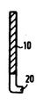
제1도는 제1실시예에 따른 체결판의 평면도.1 is a plan view of a fastening plate according to the first embodiment.
제2도는 제1도의 II-II선을 취한 체결판의 단면도.2 is a cross-sectional view of a fastening plate taken along the line II-II of FIG.
제3도는 컨테이너 프레임 요소 내에 삽입되어 거치되어 있는 상태의 제1도에 따른 체결판을 도시한 도면.3 shows the fastening plate according to FIG. 1 in a state where it is inserted into and mounted in a container frame element.
제4도는 체결판이 체결된 위치에 있는 제3도에 도시된 장치의 사시도.4 is a perspective view of the device shown in FIG. 3 with the fastening plate in the fastened position.
제5도는 제2실시예에 따른 체결판을 도시한 제1도와 유사한 평면도.FIG. 5 is a plan view similar to FIG. 1 showing a fastening plate according to the second embodiment; FIG.
제6도는 제5도에 도시된 체결판이 체결 위치에 있는 컨테이너 코너를 도시한 도면.FIG. 6 shows a container corner with the fastening plate shown in FIG. 5 in a fastening position. FIG.
제7도는 제5도에 도시된 체결판의 측면도.7 is a side view of the fastening plate shown in FIG.
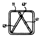
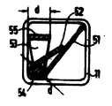
제8도, 제10도 및 제12도는 다른 실시예들에 따른 체결판들의 평면도.8, 10 and 12 are plan views of fastening plates according to other embodiments.
제9도, 제11도, 제13도, 제8도, 제10도 및 제12도에 따른 체결판들이 각각 거치되어 있는 상태를 도시한 컨테이너 프레임 요소의 개략적인 단부도.Fig. 9 is a schematic end view of a container frame element showing a state in which fastening plates according to Figs. 9, 11, 13, 8, 10 and 12 are mounted, respectively.
* 도면의 주요부분에 대한 부호의 설명* Explanation of symbols for main parts of the drawings
10 : 체결판 11 : 프레임 요소10: fastening plate 11: frame element
12, 13 : 절 췌부 15 : 후방연부12, 13: section pancreas 15: posterior edge
16, 18 : 웨브 17 : 전방면부16, 18: web 17: the front portion
20 : 연장부 21 : 코너 결속구20: extension part 21: corner fasteners
23 : 절 췌부 24, 26, 27 : 프레임 요소23: Section Pancreas 24, 26, 27: Frame Elements
29 : 요홈 30 : 기부29: home 30: donation
31 : 회전체결부 35 : 코너 개구부31: rotation fastening part 35: corner opening
36 : 보강리브 40 : 체결판36: reinforcing rib 40: fastening plate
43 : 회동부 44 : 슬로트43: rotation part 44: slot
45, 46 : 돌출부 47 : 개구부45, 46: protrusion 47: opening
48 : 절췌부 50 : 체결판48: incision 50: fastening plate
본 발명은 중공(hollow)의 장방형 단면을 갖는 하부 프레임 요소들 및 각각 코너 개구부를 구성하는 코너 결속구들이 마련된 컨테이너를 체결 부재들에 체결 또는 고정하는 체결장치에 관한 것이다.The present invention relates to a fastening device for fastening or fastening to a fastening member a container provided with lower frame elements having a hollow rectangular cross section and corner fasteners constituting corner openings, respectively.
상기한 형태의 프레임 요소들 및 코너 결속구들을 포함하는 컨테이너는 독일연방공화국 특허출원공지공보 제3,239,620호에 설명되어 있다. 여기에 포함된 개념은 두개 또는 세개만 적층될 수 있는 폭 2200mm의 중형 컨테이너에 특히 적합한 컨테이너에 관한 것이다. 화물등급 30톤(이는 300KN에 상당함)이고 6개의 층으로 적층시킬 수 있는 국제적으로 규격화된 운송 컨테이너에 마련되는, ISO에 따른 코너 결속구들을 화물등급 10톤(이는 100KN에 상당함)인 상기 중형 컨테이너에 고정하게 되면, 이 코너 결속구들은 이에 의해 중량이 증가되게 되고 적절한 치수를 갖는 프레임 요소들을 필요로 하게 되며, 이 프레임 요소들 및 코너 결속구들을 중형 컨테이너에 필요한 수치보다 3배 정도 크게 된다. 이에 반하여 상기한 출원공개공보에 기재된 코너 결속구는 경량이고 소형으로 되어 있어 중형 컨테이너들에 충분히 사용될 수 있는 형태의 대응된 경량 프레임 요소들에 사용할 수 있으나, 이 코어 결속구는 ISO 1161에 부합되지 않고 상기 규정에 규정되어 있고 규격화된 컨테이너들을 운반하는데 사용되는 차량의 적재 부분에 장착되는 회전체결장치(twistlock)와 함께 사용할 수가 없다. 더욱이, 상기한 중형 컨테이너들의 외부치수는 상기한 회전체결장치 또는 볼터들이 상기 차량에 장착되는 위치 사이의 간격과 일치되지 않는다.Containers comprising frame elements and corner fasteners of the type described above are described in Federal Patent Application Publication No. 3,239,620. The concepts contained herein relate to containers which are particularly suitable for medium containers of width 2200 mm, in which only two or three can be stacked. ISO-bound corner fasteners in an internationally standardized shipping container capable of stacking 30 tons of cargo (equivalent to 300 KN) and stacking in six layers above 10 tons of cargo (equivalent to 100 KN) When secured to a medium container, these corner fasteners thereby increase in weight and require frame elements with appropriate dimensions, and these frame elements and corner fasteners are three times larger than required for the medium container. do. On the other hand, the corner fasteners described in the above-mentioned publication can be used for the corresponding lightweight frame elements of a type that can be used for medium containers in light weight and small size, but the core fasteners are not compliant with ISO 1161. It cannot be used with a twistlock mounted on the loading portion of the vehicle specified in the regulations and used to transport standardized containers. Moreover, the external dimensions of the medium containers do not coincide with the spacing between the positions at which the fastening device or bolters are mounted on the vehicle.
본 발명의 목적은 상기 규격의 컨테이너들을 차량의 적재부분 또는 선박 갑판상에 마련되는 체결 부재들에 체결시키기 위한 체결구를 제공하는데 있다. 본 발명의 다른 목적은 국제규격 ISO 1611에 부합되지 않는 코어 결속구들을 갖는 컨테이너들을 규격화된 체결부재들, 특히 ISO 1611에 따른 회전체결장치에 체결시키기 위함이다.It is an object of the present invention to provide a fastener for fastening containers of the above dimensions to fastening members provided on a loading portion or a ship deck of a vehicle. Another object of the present invention is to fasten containers having core fasteners that do not conform to international standard ISO 1611 to standardized fastening members, in particular to a rotary fastening device according to ISO 1611.
본 발명에 따른 상기 목적을 수행할 수 있는 장치는 특허청구범위 제1항에 기재되어 있다. 위 청구범위에 따라 제공되는 체결편들은 컨테이너의 프레임 요소들 내측으로 진입될 수 있고, 각각의 코너 결속구들의 코너 개구부들을 통해 외측으로 부분적으로 돌출되며, 이 체결편들은 또한 체결 부재들에 결합되는 부분에서 규격화된 각각의 체결 부재들에 일치되는 형태로 절췌된 부분을 포함하고 이동방향에 대해 횡방향으로 마련된 두개의 각 체결부재 쌍들 사이의 설정된 간격에 각각 일치되는 크기를 갖는 변위편(transition piece)들을 구성한다. 프레임 요소들 내부에 위치되도록 함으로써, 체결편들을 경제적이고 컨테이너들에 있어서 간단한 부가물로 제조할 수가 있다.An apparatus capable of performing the above object according to the present invention is described in claim 1. Fasteners provided according to the above claims may enter into the frame elements of the container and partially protrude outwards through the corner openings of the respective corner fasteners, which fasteners are also coupled to the fastening members. A displacement piece comprising a cutout portion in conformity with each of the fastening members standardized in the portion and having a size corresponding to a predetermined spacing between each of the two pairs of fastening members provided transverse to the direction of movement; ). By being located inside the frame elements, the fastening pieces can be manufactured economically and as a simple addition to containers.
본 발명의 유리한 개선점은 종속항에 기재되어 있다. 특허청구범위 제2항은 특히 간단하고 중량을 절감할 수 있는 체결편들의 구조에 관한 것이고, 제3항 내지 6항은 체결판이 체결위치로부터 이탈되는 것을 방지하는 간단하고 기능적으로 안정성있는 방법에 관한 것이고, 제7항 내지 9항은 체결판 부분의 높이를 조절하는 방법에 관한 것이고, 제10항 및 제11항은 체결판들을 프레임 요소들 내부에 고정시킬 수 있는 방법에 관한 것이고, 제12항은 체결판을 완성된 컨테이너 프레임 내로 삽입할 수 있는 방법에 관한 것이며, 제13항은 보강방법에 관한 것이다. 특허청구범위 제14항의 특징에 따라 각각의 코너 결속구에 연결된 양하부 프레임 요소들의 방향으로 체결판들을 지지할 수 있는 장점을 마련하게 되어, 컨테이너를 대응된 체결부재에 보다 보강된 강도로 고정시킬 수가 있게 된다. 이 고정상태에 따른 보다 개선된 결과는 제15항에서 얻을 수 있는데, 이는 체결 부재를 구성하는 회전체결장치와 관련하여 특히 적합하며, 여기에서 체결판에 마련된 개구부를 통해 회전체결장치를 회전고정시킴으로써 컨테이너를 요동하지 않게 유지할 수 있게 된다. 특허청구범위 제17항에 내지 제19항에 기재된 실시예들은 폭이 증가된 체결판을 각각의 프레임 요소 단면내에 수용할 수 있는 유리한 가능성에 대해 기술한 것이다.Advantageous refinements of the invention are described in the dependent claims. Claim 2 relates to a structure of fastening pieces that can be particularly simple and save weight, and claims 3 to 6 relate to a simple and functionally stable method of preventing the fastening plate from being released from the fastening position Claims 7 to 9 relate to a method of adjusting the height of the fastening plate part, and claims 10 and 11 relate to a method that can fasten the fastening plates inside the frame elements. Relates to a method by which the fastening plate can be inserted into a finished container frame, and
이하 첨부된 도면을 참조로 하여 본 발명을 상술한다.Hereinafter, the present invention will be described in detail with reference to the accompanying drawings.
제1도 및 제2도에 도시한 평강 체결판(10)(flat-steel locking plate)의 전체폭은 B이며 이는 제3도에 도시한 장방형 및 특히 정방형 단면을 갖는 컨테이너 프레임 요소(11)들의 대각선 길이 보다 약간 짧게 되어 있다. 체결판(10)의 양 종측면 중의 하나에는 두개의 절췌부(12,13)을 마련하는데, 이중 절췌부(12)는 체결판(10)의 후방연부(15)로 직각으로 연장되며 한편, 절췌부(13)은 절췌부(12)와 함께 웨브(16)을 형성하고 체결판(12,13)의 깊이는 체결판(10)의 감소된 폭 b가 프레임 요소(11)의 폭 β(제3도) 보다 약간 작도록 구성되어 있다.The overall width of the flat-
제2도에 도시된 바와 같이, 체결판(10)에는 웨브(16,18)부분과 전방 연부(17)을 따라 장방형 굴곡부로 형성된 연장부(20)을 마련한다. 다른 방법으로는 웨브들에 비드(bead) 또는 주름을 마련할 수도 있다. 상기 연장부의 두께는 프레임 요소(11)의 하부 다리들 및 코너 결속구(21)(corner fitting)(제3도)의 재료 두께의 합과 동일하게 된다. 제4도 및 제6도에서 명백하듯이, 위와 같은 치수로 된 연장부(20)은 이에 의해 형성되는 체결판(10)의 최하부면이 코너 결속구(21)의 바닥면과 동일면 상에 위치되도록 하는 역할을 한다. 연장부는 다음에 제7도를 참조로 하여 설명하는 바와 같이 너트들을 용접하는 다른 구조로 할 수도 있다.As shown in FIG. 2, the
제1도에 도시한 체결판 웨브(16)의 폭은 이 웨브(16)이 프레임 요소(11)의 하부 외측 연부상에 제4도에서와 같이 마련된 연부구멍(22)를 통과할 수 있는 치수로 한다. 코너 결속구(21)의 형태에 따라, 연부구멍(22)는 코너 결속구(21) 자체에도 마련할 수 있으며, 제6도에 도시한 바와 같이 코너 결속구(21)상의 프레임 요소(11,24)상의 대응 절췌부(23)으로 마련할 수도 있다.The width of the
절췌부(13)의 폭 및 형상은 체결부위의 폭 및 형상에 따라 결정되며, 이는 제4도에서 실선으로 도시되어 있으며 예컨대 차량의 적재부분 상에 고정되는 볼트(25)에 일치되는 것으로 도시되어 있는데, 여기에서 프레임 요소(11), 코너 결속구(21) 및 체결판(10)으로 구성되는 컨테이너가 체결된다. 이러한 고정된 볼트들은 특히 기차의 적재부분에 마련되는데, 여기에서는 수직가속력을 지탱하기 위한 수직방향의 체결이 필요하지 않다. 특히, 볼트(25)는 ISO 1161에 따른 표준 코너 결속구들의 대응된 하부위치의 구멍들 내로 삽입될 수 있는 형태로 구성할 수도 있다. 체결판(10)의 절췌부(13)은 C형으로 3방향에서 상기 볼트(25) 주위에 결합되는 구조로 되어 있다.The width and shape of the
따라서, 제4도에 도시된 바와 같이 프레임 요소(11,26,27)과 코너 결속구(21)로 구성되는 컨테이너는 3방향, 즉 프레임 요소(11)의 종방향 연장부의 양측 방향과 프레임(27)의 종방향 연장부의 일방향에서 고정된다. 제4방향에서의 고정은 제4도에서의 프레임 요소(27)의 다른 단부 부분에서 또다른 체결판(10)을 마련함으로써 달성될 수 있는데, 상기 체결판(10)에는 제4도에 도시한 체결판(10)의 절췌부(13)에 대해 반대 방향으로 개방되고 상기 부분에 위치한 볼트에 결합되는 절췌부가 마련된다.Thus, as shown in FIG. 4, the container consisting of the
제3도는 체결판(10)을 프레임 요소(11)내로 가압시킨 상태에서 체결판이 거치되어 있는 상태를 도시한 것이다. 이 대각선 위치에서 체결판은 프레임 요소(11)에 완전히 수용된다. 코너 결속구(21)에 대면되는 프레임 요소(11)의 한쪽단부 또는 프레임 요소 내부에 체결판(10)상의 대응된 성형부(도시안됨)와 협력되는 성형부(역시 도시안됨)를 마련하여 체결판(10)이 거치 위치에 있을 때 프레임 요소 내로 깊이 활주 삽입되는 것을 방지된다.3 shows a state in which the fastening plate is mounted while the
제3도에 도시된 바와 같이 본 경우에서는 4분원 형태인 코너 결속구(21)의 코너 구멍(28)의 반경이 체결판(10)의 전체폭 B보다 작게 되어 있으므로 체결판(10)이 낙하되어 이탈되는 것이 방지된다. 컨테이너를 제작한 후에, 코너 결속구(21)을 부착하기 전에 체결판(10)을 프레임 요소(11)내로 삽입한다.As shown in FIG. 3, in this case, the radius of the
제3도에서, 프레임 요소(11)은 정방형 단면을 갖는 것으로 도시하였다. 다른 방법으로는 장방형 단면을 갖는 하부 프레임 요소들을 그 긴변이 수직이 되도록 하여 설치할 수 있다. 이 경우에, 체결판들의 전체폭 B도 따라서 크게 하여야 한다. 프레임 요소의 구멍폭 β 및 체결판의 축소폭 b는 변화하지 않기 때문에, 폭 b를 지나 돌출되는 웨브(16,18)의 길이는 증가되어 이에 의해 체결부재는 증가된 길이만큼 감싸여진다.In FIG. 3, the
사용시에, 체결할 컨테이너는 차량 횡축을 따라 배열된 두개의 볼트(25) 사이에서 각각의 적재 부분상에 상기 양 볼트들이 양 코너 결속구(21)에 인접하도록 위치시킨다. 다음에 제3도에 도시된 바와 같이 그 대각선 위치에 있는 두개의 체결판(10)들을 웨브(16)이 연부구멍(22)를 통과하는 절췌부(13)이 각각의 볼트(15) 주위에 결합되도록 외부로 당긴다. 이 위치에서 체결판(10)은 제4도에 도시한 수평위치로 되며, 여기에서 체결판은 컨테이너를 볼트(25)에 대해 체결하게 된다. 체결판(10)의 전방 연부(17)은 코너 결속구의 각 내부벽에 접하거나 또는 그 바로 앞에서 종단된다. 이 위치에서 체결판(10)은 그 저면이 프레임 요소(11)의 하부다리 상에 놓여지고 연장부(20)의 바닥면은 적재부분상에 놓여지게 된다.In use, the container to be fastened is positioned such that both bolts abut the two
연장부(20)은 체결판(10)이 제4도에 도시된 체결 위치에 있을 때 체결판(10)을 내측 방향으로 약간 경사지게 하기에 충분한 두께를 갖는데, 이는 체결판(10)이 해제 위치(거치위치)로 우발적으로 이동되는 것을 방지하는 역할을 한다.The
제5도에 도시된 체결판(10')는 제3의 중심 절췌부(14)가 마련된 것이 제1도에 도시한 체결판과 다른데, 이 절췌부는 후방 절췌부(12)와 함께 웨브(16)을 형성하고 전방 절췌부(13)과 함께 또 다른 웨브(19)를 형성한다. 또한, 제5도에 따른 체결판(10')에는 반대편 종측면에 정방 연부(17)에 대해 수직으로 연장되는 절췌부(29)를 마련하는데, 이 요홈은 경사진 위치에 있는 체결판(10')가 코너 결속구(21)로부터 코너 개구부(28)를 통해 그 대응된 길이 만큼 연장되도록 하는 역할을 한다.The
제6도에 도시된 체결 위치에서 체결판(10')의 웨브(16)은 프레임요소(11) 및 코너 결속구(21)상의 절췌부(23,24)에 의해 형성되는 연부구성(22')을 통과하며, 절췌부(13)는 본 실시예에서는 ISO 1161에 따른 회전 체결부(31)로 되어 있는 체결부재의 기부(30) 사이에 삽입된다. 체결판(10')가 코너 결속구(21)로부터 특정 거리만큼 연장되고 연장된 위치에서 절췌부(13)이 이에 대응되는 간격만큼 외측에 놓여지게 되므로, 체결부재가 코너 개구부(28)부분내에 완전히 위치한 상태로 이제 컨테이너는 체결부재에 대해 고정되게 된다. 제6도에 도시되어 있는 바와 같이 체결부재가 회전체결부로 구성될 경우에, 그 두부를 회전시켜 체결판(10')를 체결시키고 이에 의해 컨테이너를 수직방향으로 체결시키게 된다. 수직 가속방향에 대하여도 회전 체결부로 고정시키는 것은 컨테이너들을 자동차의 적재부분 상에 고정시켜 운송할 때 특히 필요하다.In the fastening position shown in FIG. 6, the
제6도에 도시된 회전 체결부의 체결 작동과 관련해서, 체결판(10')에 제2도에 도시한 굴곡부로 연장부(20)을 마련하는 대신에 대응된 두께를 갖는 너트(32)(제7도)들로 연장부를 마련하는 것이 좋은데, 상기 너트들은 웨브(16,18,19)부분에서 체결판(10')의 저면에 용접으로 결합된다. 제5도에 도시된 바와 같이, 웨브(18)에는 구멍(33)을 또한 마련하는데, 이는 너트(32)의 나사구멍과 정렬된다.In connection with the fastening operation of the rotational fastening portion shown in FIG. 6, the
체결판(10')가 제6도에 도시한 회전체결부(31)에 의해 체결될 때, 이 체결 조립체는 위로부터 너트(32)를 통과하여 그 저면으로부터 연장되게 되는 조임나사(34)에 의해 부가적인 고정력을 얻게 된다. 필요하면 동일한 조임수단이 제5도 및 제6도에 따른 웨브(19)부분에도 마련할 수 있다. 상기 조임나사들에 의해 체결판 웨브들이 상승될 때 웨브(16,19)의 측연부 사이와 연부 구멍(22)와 코너 개구부(28)의 경계연부 사이에는 부가적인 쐐기 효과가 발생되는데, 이 쐐기 효과는 체결 조립체의 강도를 증가시키는 역할을 한다.When the fastening plate 10 'is fastened by the
제5도에 점선으로 도시된 바와 같이, 코너 요홈(29)는 후방으로 상당 거리만큼 연장되어, 후방을 향한 연장된 코너 개구부(35)를 형성하는 절췌부가 웨브(16) 및 절췌부(14) 사이에 형성된 연부와 대체로 정렬되게 한다. 이러한 구조로 해서 코너 결속구(21)을 고정시킨 후에라도 코너 결속구의 코너 개구부(28)을 통하여 체결판(10')를 프레임 요소(11)내로 삽입시킬 수 있으나, 이 경우에 체결판은 우발적으로 이탈되지 않도록 강하게 유지된다. 본 체결판에서 웨브(16) 부분에만 유지되는 전체폭 B는 체결판(10')가 적절한 기능을 수행하는데 충분하다. 체결판(10')의 강도를 증진시키기 위해 그 상부면에 판의 종방향으로 연장된 보강리브(36)을 마련할 수도 있다. 필요하면 리브를 웨브(16,18,19)부분 내로 연장된 단면으로 할 수도 있다. 필요한 강도를 판재료의 두께에 의해서만 얻을 수 없는 경우에는 제1도에 따른 체결판(10)에도 유사한 보강리브를 사용할 수 있다.As shown in dashed lines in FIG. 5, the
제8도에 도시된 체결판(40)은 개략적으로 도시한 회동부(43)에 의해 상호 연결된 두개의 판(41,42)로 구성되어 있다. 그 좌측단에서 판(41)은 제1도의 폭 b와 일치하는 폭 b인 부분을 갖는데, 이는 제3도에 도시한 프레임 요소(11)의 구멍폭 β에 비해서 약간 작다. 판(41)의 주부분은 보다 큰 폭을 가지며 회동부의 반대방향에서 판(41)의 연부로부터 연장된 슬로트(44)를 포함하여, 상기 연부에 두개의 돌출부(45,46)을 형성한다. 판(42)에는 ISO 1161에 따른 회전 체결부 상에 삽입될 수 있는 형태로 된 타원형 개구부(47)을 마련한다. 제8도에 도시된 실시예에서, 회동부(43)의 축은 개구부(47)의 내측 연부를 따라 연장된다.The fastening plate 40 shown in FIG. 8 consists of two
제9도는 제8도 도시 체결판(40)이 그 거치 위치로 프레임 요소(11) 내로 완전히 삽입되는 방법을 도시한 것이다. 컨테이너를 고정하기 위해, 프레임 요소(11)에 대해 수직으로 연장된 하부 프레임 요소(27)이 코너 결속구(21)에서 종결되는 부분에 돌출부(45)가 위치할 수 있는 거리만큼 체결판(40)을 프레임 요소로부터 꺼낸다. 체결판(40)을 직선 상태로 펼쳤을 때, 슬로트(44)는 코너 결속구(21)의 벽에 결합되고, 돌출부(46)은 코너 결속구(21) 외측에 위치하게 된다. 개구부(47)은 체결부재를 감싼다. 이 경우에 체결부재는 회전체결부로 구성되며, 회전 체결부를 90°회전시킴으로써 체결판(40)을 유지하게 되어, 컨테이너를 활주 및 요동을 하지 못하도록 고정하게 된다.9 illustrates how the fastening plate 40 shown in FIG. 8 is fully inserted into the
제10도에 도시된 체결판(40')는 회동부(43')의 축이 개구부(47) 외측에 위치하여 양 판(41',42')가 동일폭을 갖도록 한 것이 제8도 도시 체결판(40)과 구별된다. 이 경우에, 회동부(43')는 절췌부(48)에서 그 좌측단에서 종단된다. 제11도는 제10도 도시 체결판(40')가 프레임 요소(11) 내에서 거치되는 방법을 도시한 것이다.In the fastening plate 40 'shown in FIG. 10, the shaft of the pivoting portion 43' is located outside the opening 47 so that both plates 41 'and 42' have the same width. It is distinguished from the fastening plate 40. In this case, the pivot 43 'is terminated at its left end in the cutout 48. FIG. 11 illustrates how the FIG. 10 fastening plate 40 ′ is mounted within the
제12도 및 제13도에 도시된 체결판(50)은 판(51)을 갖는데, 그 주부분은 제8도 도시 판(41)의 형태와 일치한다. 슬로트(44)의 반대측인 연부에서 판(51)과 일체로 중첩부(52)가 형성되는데, 이 중첩부(52)는 링(53)을 통해 연장되고 판(51)의 주부분상으로 접혀진다. 제13도에 도시된 바와 같이, 링(53)의 내측부(54)는 원형이고 링(53)은 판(51)에 회동형으로 회동 자재하게 연결된다. 링(53)의 링 외측부(55)는 내측부(54)의 두께와 판(51)의 두께의 2배의 합과 동일한 두께로 되어 있다. 이 치수는 제13도에 d로 표시하였으며 이 두께는 체결판(50)의 작동 위치에서 판(51)이 프레임 요소(11)의 내부면 상에 평면으로 위치할 때 링 외측부(55)가 지지부상에 수직으로 직립될 수 있도록 선택된다. 회동부를 형성하는 중첩부(52)의 적합한 두께면에서 볼 때 링(53)의 구멍 치수는 제8도 및 제10도의 체결판에서의 개구부(47)의 형태와 일치한다.The
상기한 모든 실시예들에서 체결판은 프레임 요소(11) 내로 삽입되어 그에 대해 고정되며, 컨테이너를 체결 또는 고정하는데 사용되진 않을 때는 방출한다. 다른 방법으로는, 프레임 요소(11) 또는 프레임 요소(27)에 코너 결속구(21)에 인접하여 그 상부 내측연부에 슬로트를 마련하여, 체결판을 상기 슬로트를 통해 각각의 프레임 요소에 삽입할 수도 있다. 이 체결판 보관방법은 체결판의 전체 폭이 프레임 요소 구멍의 대각선 길이 보다 크고 체결판이 회동부를 갖지 않을 경우에 적합하다.In all of the above embodiments the fastening plate is inserted into and secured to the
Claims (19)
Applications Claiming Priority (2)
| Application Number | Priority Date | Filing Date | Title |
|---|---|---|---|
| DEP3501969.7 | 1985-01-22 | ||
| DE19853501969 DE3501969A1 (en) | 1985-01-22 | 1985-01-22 | DEVICE FOR LOCKING A CONTAINER |
Publications (2)
| Publication Number | Publication Date |
|---|---|
| KR860005738A KR860005738A (en) | 1986-08-11 |
| KR910006186B1 true KR910006186B1 (en) | 1991-08-16 |
Family
ID=6260426
Family Applications (1)
| Application Number | Title | Priority Date | Filing Date |
|---|---|---|---|
| KR1019860000346A KR910006186B1 (en) | 1985-01-22 | 1986-01-21 | Device for locking a container |
Country Status (14)
| Country | Link |
|---|---|
| US (1) | US4682923A (en) |
| EP (1) | EP0189054B1 (en) |
| JP (1) | JPS61203392A (en) |
| KR (1) | KR910006186B1 (en) |
| CN (1) | CN85101117B (en) |
| AT (1) | ATE56920T1 (en) |
| AU (1) | AU585928B2 (en) |
| BR (1) | BR8600232A (en) |
| CA (1) | CA1249531A (en) |
| DE (2) | DE3501969A1 (en) |
| ES (1) | ES296447Y (en) |
| HK (1) | HK21791A (en) |
| SU (1) | SU1558297A3 (en) |
| ZA (1) | ZA86295B (en) |
Families Citing this family (12)
| Publication number | Priority date | Publication date | Assignee | Title |
|---|---|---|---|---|
| DE3615354C1 (en) * | 1986-05-06 | 1987-09-17 | Westerwaelder Eisen Gerhard | Arrangement for locking a container |
| DE8708562U1 (en) * | 1987-06-19 | 1988-10-20 | Westerwaelder Eisenwerk Gerhard Gmbh, 5241 Weitefeld, De | |
| EP0483605A3 (en) * | 1990-11-02 | 1992-05-20 | Westerwaelder Eisenwerk Gerhard Gmbh | Arrangement for fixing of a loading unit |
| DE9015209U1 (en) * | 1990-11-05 | 1992-03-05 | Westerwaelder Eisenwerk Gerhard Gmbh, 5241 Weitefeld, De | |
| GB2319017B (en) * | 1996-11-07 | 2000-08-30 | Bell Lines Ltd | Freight containers |
| US6315141B1 (en) * | 1999-03-26 | 2001-11-13 | James Brennan, Jr. | Shipping box lockdown |
| ATE349384T1 (en) * | 2003-04-16 | 2007-01-15 | Garofoli Spa | SYSTEM FOR SECURING PROTECTION ROOMS OR THE LIKE |
| SE527501C2 (en) * | 2004-04-01 | 2006-03-21 | All Set Marine Lashing Ab | Turn the locking device |
| WO2006041301A1 (en) * | 2004-10-14 | 2006-04-20 | Ragnar Vidum | Cargo securement device on carriers |
| CN104228658B (en) * | 2014-08-29 | 2016-06-08 | 江苏捷诚车载电子信息工程有限公司 | Vertical or horizontal put the fixing device of rotation lock that shelter all can lock |
| US10155621B1 (en) * | 2016-04-25 | 2018-12-18 | Precision Maintenance & Fabrication, LLC | Sea container bracket |
| CN115248015B (en) * | 2022-09-23 | 2022-12-06 | 四川鑫跃鑫科学仪器有限公司 | A device for buried pipeline nondestructive test |
Family Cites Families (10)
| Publication number | Priority date | Publication date | Assignee | Title |
|---|---|---|---|---|
| US1407594A (en) * | 1920-06-09 | 1922-02-21 | Alfred H Smith | Compartment freight car |
| NL246597A (en) * | 1959-05-04 | |||
| SE318827B (en) * | 1968-06-17 | 1969-12-15 | Seasafe Transport Ab | |
| US3709455A (en) * | 1970-08-24 | 1973-01-09 | Peck & Hale | Tie down device |
| US3722714A (en) * | 1971-09-14 | 1973-03-27 | Peck & Hale | Container interconnection arrangement |
| GB1543711A (en) * | 1974-11-30 | 1979-04-04 | Hutsons Ltd | Coupling devices for use in lifting cargo containers |
| US4280811A (en) * | 1979-07-02 | 1981-07-28 | W. R. Grace & Co., Cryovac Division | Bag dispenser |
| EP0054881B1 (en) * | 1980-12-23 | 1984-10-24 | Westerwälder Eisenwerk Gerhard GmbH | Corner fittings for freight containers |
| DE3239620C2 (en) * | 1982-10-26 | 1985-01-24 | Westerwaelder Eisenwerk Gerhard Gmbh, 5241 Weitefeld | Freight container |
| EP0097269B1 (en) * | 1982-06-18 | 1987-10-14 | Westerwälder Eisenwerk Gerhard GmbH | Corner fittings for freight containers |
-
1985
- 1985-01-22 DE DE19853501969 patent/DE3501969A1/en active Granted
- 1985-04-01 CN CN85101117A patent/CN85101117B/en not_active Expired
-
1986
- 1986-01-08 EP EP86100187A patent/EP0189054B1/en not_active Expired - Lifetime
- 1986-01-08 DE DE8686100187T patent/DE3674420D1/en not_active Expired - Fee Related
- 1986-01-08 AT AT86100187T patent/ATE56920T1/en not_active IP Right Cessation
- 1986-01-13 AU AU52218/86A patent/AU585928B2/en not_active Ceased
- 1986-01-15 ZA ZA86295A patent/ZA86295B/en unknown
- 1986-01-16 US US06/819,366 patent/US4682923A/en not_active Expired - Fee Related
- 1986-01-21 SU SU864012603A patent/SU1558297A3/en active
- 1986-01-21 ES ES1986296447U patent/ES296447Y/en not_active Expired - Fee Related
- 1986-01-21 CA CA000500032A patent/CA1249531A/en not_active Expired
- 1986-01-21 BR BR8600232A patent/BR8600232A/en not_active IP Right Cessation
- 1986-01-21 KR KR1019860000346A patent/KR910006186B1/en not_active IP Right Cessation
- 1986-01-22 JP JP61012933A patent/JPS61203392A/en active Granted
-
1991
- 1991-03-21 HK HK217/91A patent/HK21791A/en unknown
Also Published As
| Publication number | Publication date |
|---|---|
| CN85101117A (en) | 1986-08-20 |
| SU1558297A3 (en) | 1990-04-15 |
| CA1249531A (en) | 1989-01-31 |
| EP0189054A3 (en) | 1988-12-07 |
| CN85101117B (en) | 1988-09-14 |
| HK21791A (en) | 1991-03-28 |
| ZA86295B (en) | 1986-09-24 |
| EP0189054B1 (en) | 1990-09-26 |
| AU5221886A (en) | 1986-07-31 |
| JPS61203392A (en) | 1986-09-09 |
| AU585928B2 (en) | 1989-06-29 |
| ATE56920T1 (en) | 1990-10-15 |
| ES296447U (en) | 1989-05-01 |
| DE3501969A1 (en) | 1986-07-24 |
| KR860005738A (en) | 1986-08-11 |
| DE3501969C2 (en) | 1987-01-22 |
| BR8600232A (en) | 1986-09-30 |
| ES296447Y (en) | 1990-03-16 |
| JPH0260588B2 (en) | 1990-12-17 |
| EP0189054A2 (en) | 1986-07-30 |
| US4682923A (en) | 1987-07-28 |
| DE3674420D1 (en) | 1990-10-31 |
Similar Documents
| Publication | Publication Date | Title |
|---|---|---|
| KR910006186B1 (en) | Device for locking a container | |
| US4844672A (en) | Interlocking adapter casting | |
| EP0130663B1 (en) | Captive dunnage fitting | |
| US4914874A (en) | System for interconnecting panels of containers | |
| US6460724B1 (en) | Tote box with interengaging top rail | |
| US4591307A (en) | Corner fitting with retractable twist lock | |
| US6592025B2 (en) | Tote box with corner enhancers, clips and top rail | |
| US4044693A (en) | Inflatable dunnage with tie-downs | |
| US5474230A (en) | Folding box | |
| US20020079359A1 (en) | Tote box with multiple piece top rail including corner pieces with projections | |
| JPH026707B2 (en) | ||
| US5494167A (en) | Returnable case | |
| US5505323A (en) | Container capable of being assembled by interlocking connections | |
| WO2002018217A1 (en) | Collapsible bin | |
| US4944421A (en) | Angle reinforcement | |
| JP2823009B2 (en) | Double pallet | |
| US6305601B1 (en) | Tote box with corner enhancers and top rail | |
| GB2101963A (en) | Improvements relating to pallets or stillages | |
| US5115933A (en) | Freight container | |
| KR920001608Y1 (en) | Foldable box | |
| JP4291059B2 (en) | container | |
| US4593831A (en) | Containers | |
| KR920007062B1 (en) | Arrangement for locking loading units | |
| JP3140959B2 (en) | Pallet containers | |
| GB2152127A (en) | Sliding bolt fastening |
Legal Events
| Date | Code | Title | Description |
|---|---|---|---|
| A201 | Request for examination | ||
| E902 | Notification of reason for refusal | ||
| G160 | Decision to publish patent application | ||
| E701 | Decision to grant or registration of patent right | ||
| GRNT | Written decision to grant | ||
| LAPS | Lapse due to unpaid annual fee |