KR910004223B1 - Oxigen sensor and combustion gas ratio control device engine - Google Patents
Oxigen sensor and combustion gas ratio control device engine Download PDFInfo
- Publication number
- KR910004223B1 KR910004223B1 KR1019880002625A KR880002625A KR910004223B1 KR 910004223 B1 KR910004223 B1 KR 910004223B1 KR 1019880002625 A KR1019880002625 A KR 1019880002625A KR 880002625 A KR880002625 A KR 880002625A KR 910004223 B1 KR910004223 B1 KR 910004223B1
- Authority
- KR
- South Korea
- Prior art keywords
- oxygen
- gas
- detected
- oxygen sensor
- sensor
- Prior art date
Links
Images


Classifications
-
- G—PHYSICS
- G01—MEASURING; TESTING
- G01N—INVESTIGATING OR ANALYSING MATERIALS BY DETERMINING THEIR CHEMICAL OR PHYSICAL PROPERTIES
- G01N27/00—Investigating or analysing materials by the use of electric, electrochemical, or magnetic means
- G01N27/26—Investigating or analysing materials by the use of electric, electrochemical, or magnetic means by investigating electrochemical variables; by using electrolysis or electrophoresis
-
- F—MECHANICAL ENGINEERING; LIGHTING; HEATING; WEAPONS; BLASTING
- F02—COMBUSTION ENGINES; HOT-GAS OR COMBUSTION-PRODUCT ENGINE PLANTS
- F02D—CONTROLLING COMBUSTION ENGINES
- F02D41/00—Electrical control of supply of combustible mixture or its constituents
- F02D41/02—Circuit arrangements for generating control signals
- F02D41/14—Introducing closed-loop corrections
- F02D41/1438—Introducing closed-loop corrections using means for determining characteristics of the combustion gases; Sensors therefor
- F02D41/1473—Introducing closed-loop corrections using means for determining characteristics of the combustion gases; Sensors therefor characterised by the regulation method
- F02D41/1475—Regulating the air fuel ratio at a value other than stoichiometry
-
- G—PHYSICS
- G01—MEASURING; TESTING
- G01N—INVESTIGATING OR ANALYSING MATERIALS BY DETERMINING THEIR CHEMICAL OR PHYSICAL PROPERTIES
- G01N27/00—Investigating or analysing materials by the use of electric, electrochemical, or magnetic means
- G01N27/26—Investigating or analysing materials by the use of electric, electrochemical, or magnetic means by investigating electrochemical variables; by using electrolysis or electrophoresis
- G01N27/403—Cells and electrode assemblies
- G01N27/406—Cells and probes with solid electrolytes
- G01N27/407—Cells and probes with solid electrolytes for investigating or analysing gases
- G01N27/4077—Means for protecting the electrolyte or the electrodes
-
- G—PHYSICS
- G01—MEASURING; TESTING
- G01N—INVESTIGATING OR ANALYSING MATERIALS BY DETERMINING THEIR CHEMICAL OR PHYSICAL PROPERTIES
- G01N1/00—Sampling; Preparing specimens for investigation
- G01N1/28—Preparing specimens for investigation including physical details of (bio-)chemical methods covered elsewhere, e.g. G01N33/50, C12Q
- G01N1/40—Concentrating samples
- G01N1/405—Concentrating samples by adsorption or absorption
Landscapes
- Chemical & Material Sciences (AREA)
- Health & Medical Sciences (AREA)
- Engineering & Computer Science (AREA)
- Life Sciences & Earth Sciences (AREA)
- Physics & Mathematics (AREA)
- Analytical Chemistry (AREA)
- Pathology (AREA)
- Molecular Biology (AREA)
- Chemical Kinetics & Catalysis (AREA)
- Electrochemistry (AREA)
- Immunology (AREA)
- General Physics & Mathematics (AREA)
- Biochemistry (AREA)
- General Health & Medical Sciences (AREA)
- General Engineering & Computer Science (AREA)
- Combustion & Propulsion (AREA)
- Mechanical Engineering (AREA)
- Measuring Oxygen Concentration In Cells (AREA)
- Investigating Or Analyzing Materials By The Use Of Fluid Adsorption Or Reactions (AREA)
- Electrical Control Of Air Or Fuel Supplied To Internal-Combustion Engine (AREA)
Abstract
내용 없음.No content.
Description
제 1 도는 종래의 산소 센서의 개념적 구성을 도시하는 종단면도.1 is a longitudinal sectional view showing a conceptual configuration of a conventional oxygen sensor.
제 2 도는 종래의 다른 형태의 산소 센서의 개념적 구성을 도시한 종단면도.2 is a longitudinal sectional view showing a conceptual configuration of another conventional oxygen sensor.
제 3 도는 제 2 도의 III-III선에 따른 단면도.3 is a cross-sectional view taken along the line III-III of FIG.
제 4 도는 종래 니연기관의 공연비 제어 장치의 개념적 구성을 도시하는 블록도.4 is a block diagram showing a conceptual configuration of an air-fuel ratio control device of a conventional knee combustion engine.
제 5a 도 내지 제 5c 도는 종래의 산소 센서를 사용하여 공연비 제어를 행한 경우의 기관에 공급되는 혼합기의 공연비에 대응시켜 표시한, 배기 통로의 산소 센서 근방 및 산소 센서의 전극부 근방의 각 산소 농도, 산소 센서가 출력하는 산소 농도 검출 신호치 및 연료 분사 밸브의 연료 분사량을 보정하는 피이드 백 보정 계수치 K1의 각 시간 변화의 관계를 설명하기 위한 타이밍 챠트.5A to 5C show respective oxygen concentrations in the vicinity of the oxygen sensor in the exhaust passage and in the vicinity of the electrode portion of the oxygen sensor, which are displayed in correspondence with the air-fuel ratio of the mixer supplied to the engine when the air-fuel ratio control is performed using a conventional oxygen sensor. And a timing chart for explaining the relationship between the oxygen concentration detection signal value output from the oxygen sensor and the feed back correction coefficient value K 1 for correcting the fuel injection amount of the fuel injection valve.
제 6 도는 본 발명의 산소 센서의 개념적 구성을 도시하며 산소 검출 소자 주위에 산소 저장 물질을 보유하는 펠릿이 충전된 타입의 종단면도.6 is a longitudinal sectional view of a type filled with pellets holding an oxygen storage material around an oxygen detection element, showing a conceptual configuration of the oxygen sensor of the present invention.
제 7 도는 본 발명의 다른 형태의 산소 센서의 개념적 구성을 도시하며, 제 6 도에 도시한 센서와 마찬가지의 펠릿 타입의 종단면도.FIG. 7 shows a conceptual configuration of an oxygen sensor of another embodiment of the present invention, and is a longitudinal cross-sectional view of a pellet type similar to the sensor shown in FIG.
제 8 도는 본 발명의 또다른 형태의 산소 센서의 개념적 구성을 도시하며, 보호층에 산소 저장 물질을 보유시키는 타입의 종단면도.8 shows a conceptual configuration of another type of oxygen sensor of the present invention, the longitudinal cross section of the type holding oxygen storage material in the protective layer.
제 9 도는 본 발명의 또다른 형태의 산소 센서의 개념적 구성을 도시하며, 완충층에 산소 저장 물질을 보유시키는 타입의 종단면도.9 shows a conceptual configuration of another type of oxygen sensor of the present invention, a longitudinal cross-sectional view of a type for retaining an oxygen storage material in a buffer layer.
제 10 도는 본 발명의 또다른 형태의 산소 센서의 개념적 구성을 도시하며, 산소 저장 물질을 보유시킨 완충층과 전극사이에 보호층이 개재되는 타입의 종단면도.10 shows a conceptual configuration of another type of oxygen sensor of the present invention, wherein a longitudinal cross section of a type is provided with a protective layer interposed between a buffer layer and an electrode holding an oxygen storage material.
제 11 도는 본 발명의 또다른 형태의 산소 센서의 개념적 구성을 도시하며, 완충층에 산소 저장 물질을 보유시키는 타입의 종단면도.Figure 11 shows a conceptual configuration of another type of oxygen sensor of the present invention, in which a longitudinal cross-sectional view of the type holding oxygen storage material in the buffer layer.
제 12 도는 제 11 도의 XII-XII선에 따른 단면도.12 is a cross-sectional view taken along line XII-XII in FIG.
제 13 도는 본 발명의 또다른 형태의 산소 센서의 개념적 구성을 도시하며, 다공질 층에 산소 저장 물질을 보유시키는 타입의 종단면도.13 shows a conceptual configuration of another type of oxygen sensor of the present invention, the longitudinal cross section of the type of retaining the oxygen storage material in the porous layer.
제 14 도는 제 13 도의 XIV-XIV선에 따른 단면도.14 is a cross-sectional view taken along line XIV-XIV in FIG.
제 15 도는 본 발명의 산소 센서를 사용하여 공연비 제어를 행한 경우의 기관에 공급되는 혼합기의 공연비에 대응시켜 표시한 배기 통로의 산소 센서 근방 및 산소 센서의 전극부 근방의 각 산소 농도의 시간 변화의 관계를 설명하기 위한 타이밍 차트.Fig. 15 shows the time variation of the oxygen concentration in the vicinity of the oxygen sensor in the exhaust passage and in the vicinity of the electrode part of the oxygen sensor displayed in correspondence with the air-fuel ratio of the mixer supplied to the engine when the air-fuel ratio control is performed using the oxygen sensor of the present invention. Timing chart to illustrate the relationship.
제 16 도는 산소 저장 물질을 적량을 초과하여 과잉 보유시킨 담체를 갖는 산소 센서를 사용하여 공연비 제어를 행한 경우의 제 15 도와 유사한 산소 농도의 시간 변화의 관계를 도시한 타이밍 차트.FIG. 16 is a timing chart showing a relationship of time variation of oxygen concentration similar to that of FIG. 15 when the air-fuel ratio control is performed using an oxygen sensor having a carrier in which an oxygen storage material is excessively held in excess.
제 17 도는 본 발명의 내연기관의 공연비 제어 장치의 개념적 구성을 도시하는 블록도.17 is a block diagram showing the conceptual configuration of an air-fuel ratio control device for an internal combustion engine of the present invention.
제 18 도는 제 17 도에 도시한 공연비 제어 장치의 배기 가스 특성 평가 시험 결과를 도시하며 NOx와 CO의 각 배출량의 관계를 도시하는 그래프.FIG. 18 is a graph showing the results of the exhaust gas characteristic evaluation test of the air-fuel ratio control device shown in FIG. 17, and showing the relationship between the respective emissions of NOx and CO.
제 19 도는 제 18 도와 마찬가지로 배기 가스 특성 평가 시험을 도시하며 NOx와 CO의 배출량 관계의 그래프.19 is a graph of the emission relationship between NOx and CO, showing an exhaust gas characteristic evaluation test similarly to FIG.
제 20 도는 제 17 도에 도시한 공연비 제어 장치의 OSC 보유량과 NOx, CO, HC의 각 배출 지수의 관계를 도시하는 그래프.FIG. 20 is a graph showing the relationship between the OSC holding amount of the air-fuel ratio control device shown in FIG. 17 and the emission indexes of NOx, CO, and HC.
* 도면의 주요부분에 대한 부호의 설명* Explanation of symbols for main parts of the drawings
1c : 산소센서 2 : 보호관1c: oxygen sensor 2: protective tube
5,6 : 전극 7 : 보호층5,6 electrode 7: protective layer
12 : 지지체 13 : 검출 소자12 support 13 detection element
14 : 칩 17 : 히터14: chip 17: heater
18 : 전원 단자 19 : 출력 단자18: power supply terminal 19: output terminal
20 : 접지 단자 31 : 내연기관20: ground terminal 31: internal combustion engine
33 : 3원 촉매33: three-way catalyst
본 발명은 예를들어 차량용 내연기관의 공연비 제어에 적합하게 사용되는 산소 센서 및 그 산소 센서를 적용한 내연기관의 공연비 제어 장치에 관한 것이다.The present invention relates to, for example, an oxygen sensor suitably used for controlling the air-fuel ratio of an internal combustion engine for a vehicle, and an air-fuel ratio control apparatus for an internal combustion engine to which the oxygen sensor is applied.
자동차 등의 내연기관에 있어서는 기관 성능을 최대한으로 인출하기 위해, 기간에 공급되는 혼합기의 공연비를 이론 공연비 근방으로 항상 제어하는 것이 바람직하다. 또, 배기 가스중의 유해 물질을 정화하기 위해 사용되는 3원 촉매가 상기한 이론 공연비 근방의 극히 좁은 영역으로 제어된 공연비를 갖는 혼합기를 연소시킨 배기 가스중의 CO, NOx, HC를 동시에 고정화율로 정화하는 촉매 성능을 발휘한다는 점에서도 전술한 공연비 제어는 극히 중요하다.In an internal combustion engine such as an automobile, it is preferable to always control the air-fuel ratio of the mixer supplied in the period near the theoretical air-fuel ratio in order to take out the engine performance to the maximum. In addition, the three-way catalyst used to purify the harmful substances in the exhaust gas simultaneously fixes the CO, NOx and HC in the exhaust gas in which a mixer having a controlled air-fuel ratio is burned to an extremely narrow region near the theoretical air-fuel ratio. The above-described air-fuel ratio control is also very important in that it exhibits catalytic performance to purify.
이러한 내연기관의 공연비 제어에는 공연비 제어 장치가 사용되고, 이 공연비 제어 장치는 예를들어 내연기관의 배기 통로의 3원 촉매 상류측에 배치된 산소 센서가 출력하는 산소 농도 검출 신호에 따라 연료 분사 밸브의 연료 분사량을 제어하는 것이다.An air-fuel ratio control device is used to control the air-fuel ratio of such an internal combustion engine, and the air-fuel ratio control device is, for example, in response to an oxygen concentration detection signal output from an oxygen sensor disposed upstream of the three-way catalyst in the exhaust passage of the internal combustion engine. It is to control the fuel injection amount.
보다 구체적으로 기관에 공급되는 혼합기의 공연비가 이론 공연비에 대해 연료 풍부측으로부터 연료 희박측으로, 또는 그 반대로 연료 희박측으로부터 연료 풍부측으로 변화하면 배기 가스중의 산소 농도가 변화하고, 이에 수반하여 산소 센서의 출력치도 소정 판별치 Vx를 가로질러 변화한다. 전자 제어 장치는 이 산소 센서의 출력치, 구체적으로 상기 소정 판별 Vx에 대한 센서 출력치 변화의 방향 및 센서 출력치가 소정 판별치 Vc를 가로지른 시점으로부터의 경과 시간에 따라 연료 공급량을 증감하고, 공연비를 이론 공연비 근방으로 제어하는 것이다.More specifically, when the air-fuel ratio of the mixer supplied to the engine changes from the fuel rich side to the fuel lean side or vice versa with respect to the theoretical air-fuel ratio, the oxygen concentration in the exhaust gas changes, and thus the oxygen sensor The output value of also changes across the predetermined discrimination value Vx. The electronic controller increases or decreases the fuel supply amount according to the output value of the oxygen sensor, specifically, the direction of the sensor output value change with respect to the predetermined determination Vx and the elapsed time from the time when the sensor output value crosses the predetermined determination value Vc, Is controlled near the theoretical air-fuel ratio.
이러한 공연비 제어에 사용되는 산소 센서로서는 산소 이온 전도성 고체 전해질을 한쌍의 전극으로 협지하고, 각각의 전극을 다른 산소 농도의 분위기에 접촉시켜서 산소 농염 전지를 형성하고, 이 전지의 기전력에 의해 피검출 가스중의 산소 농도를 측정하는 것이 실용화 되어 있다.As an oxygen sensor used for such an air-fuel ratio control, an oxygen ion conductive solid electrolyte is sandwiched with a pair of electrodes, each electrode is brought into contact with an atmosphere having a different oxygen concentration to form an oxygen concentrated salt battery, and the gas to be detected is caused by the electromotive force of the battery. It is practical to measure the oxygen concentration in water.
이 종래의 산소 센서는 예를들어 산소 이온 전도성 고체 전해질의 양측을 다공질의 백금(Pt)등 가스투과성을 갖는 전극으로 끼우고, 또 이들 전극중 피검출 가스에 접촉하는 측의 전극 표면에 다공질 세라믹스로 이루어지는 보호층을 형성한 것이 사용되고 있다.In this conventional oxygen sensor, for example, both sides of an oxygen ion conductive solid electrolyte are sandwiched by electrodes having gas permeability such as porous platinum (Pt), and porous ceramics are formed on the electrode surface on the side of the electrodes in contact with the gas to be detected. What formed the protective layer which consists of is used.
또 다른 산소 센서로서는 예를들면 알루미나 등으로 이루어지는 절연 지지체와, 이 절연 지지체내에 배치된 산소 농도 검출 소자로 구성되는 것이 알려져 있다. 이 센서의 산소 농도 검출 소자는 지지체의 한쪽 측면에 형성된 직사각형 요부의 한쪽면이 노출하도록 배치된 칩과, 상기 칩의 배면에 접속되고 이 전기 저항의 변화를 검출하기 위한 한쌍의 Pt 전극으로 구성된다. 이 칩은 예를들면 산화 티탄(TiO2)등, 산소와 접촉함으로써 이 산소 농도에 따라 내부 전기 저항이 변화하는 물질로 형성되어 있다.As another oxygen sensor, for example, an insulating support made of alumina or the like and an oxygen concentration detecting element disposed in the insulating support are known. The oxygen concentration detecting element of the sensor is composed of a chip arranged so as to expose one side of a rectangular recess formed on one side of the support, and a pair of Pt electrodes connected to the back of the chip to detect a change in the electrical resistance. . The chip is made of a material in which the internal electrical resistance changes according to the oxygen concentration by contact with oxygen such as titanium oxide (TiO 2 ).
그러나, 종래의 산소 센서는 일반적으로 응답성이 낮고, 예를들어 자동차 가속시등 공연비가 일단 대폭적으로 희박측으로 이행한 경우, 그후 실제로는 공연비가 이론치 근방으로 복귀하여 풍부측으로 이행되고 있는 데도 불구하고 산소 센서는 전자 제어 장치에 여전히 희박 신호를 계속 보낸다는 결점이 있다. 이 산소 센서의 응답 지연에 기인하여 가속 종료후에 원래는 기관에 공급되는 혼합기의 공연비는 곧바로 이론치 근방의 값으로 제어해야 하지만 풍부측으로 크게 이탈하는 소위 풍부 이탈(Rich Excursion)이 발생한다.However, conventional oxygen sensors generally have low responsiveness. For example, when the air-fuel ratio such as automobile acceleration has once shifted to the lean side, even though the air-fuel ratio has actually returned to near the theoretical value and then shifted to the rich side, The oxygen sensor has the drawback that it still sends a lean signal to the electronic control unit. Due to the delay of the response of the oxygen sensor, the air-fuel ratio of the mixer originally supplied to the engine after the end of the acceleration should be controlled to a value near the theoretical value, but there is a so-called rich excursion that deviates greatly to the rich side.
또, 기관에 공급되는 혼합기의 공연비가 반대로 풍부측으로 일단 대폭 이행한 후, 이론 공연비 근방으로 복귀하는 경우에도 센서의 응답 지연에 의해 산소 센서는 풍부 신호를 계속 보낸다는 결점이 있다.In addition, even when the air-fuel ratio of the mixer supplied to the engine is largely shifted to the rich side once, and then returns to the vicinity of the theoretical air-fuel ratio, there is a drawback that the oxygen sensor continues to send the rich signal due to the delay of the sensor response.
이와같이, 기관에 공급되는 혼합기의 공연비가 이론치로부터 벗어나면 3원 촉매인 CO, HC, NOx의 정화능력이 격감되어버리고, 배기 가스중의 이들의 농도가 증가한다는 문제가 생긴다.In this way, if the air-fuel ratio of the mixer supplied to the engine deviates from the theoretical value, the purification ability of the three-way catalysts CO, HC, and NOx decreases, and there arises a problem that their concentration in the exhaust gas increases.
이런 문제를 해결하기 위해, 종래 백금에 로듐 및 적어도 한 종류의 희토류 원소 산화물을 첨가한 도전성 재료를 전극으로서 이용함으로써 전극의 촉매 활성을 높이고, 산소 센서의 응답 속도를 높인 것이 일본국 특허공개 소60-256046호 공보에 의해 알려져 있다.In order to solve this problem, conventionally, a conductive material containing rhodium and at least one rare earth element oxide added to platinum is used as an electrode to increase the catalytic activity of the electrode and to increase the response speed of the oxygen sensor. Known by the publication -256046.
또, 산소 센서를 3원 촉매의 상류에 배치하고 산소 센서 자신 혹은 그 상류에 3원 촉매와 같은 촉매 성능을 갖는 촉매체를 배치하여 산소 센서의 공연비에 대한 산소 농도 검출 특성이 급변하는 위치와 3원 촉매의 최적 정화율이 얻어지는 공연비 위치를 일치시킴으로써 3원 촉매를 유효하게 작동시키는 배기 가스 정화 장치가 일본국 특허공고 소 57-12002호 공보에 의해 알려져 있다.In addition, the oxygen sensor is placed upstream of the three-way catalyst and the catalyst body having the same catalytic performance as that of the three-way catalyst is placed on the oxygen sensor itself or upstream, so that the oxygen concentration detection characteristic with respect to the air-fuel ratio of the oxygen sensor changes rapidly. An exhaust gas purifying apparatus for effectively operating a three-way catalyst by matching the air-fuel ratio position at which the optimum purification rate of the original catalyst is obtained is known from Japanese Patent Laid-Open No. 57-12002.
본 발명의 주된 목적은 배기 가스중의 산소 농도 변화를 가능한한 빠르게 검출할 수 있는 산소 센서를 제공하는데 있다.The main object of the present invention is to provide an oxygen sensor capable of detecting a change in oxygen concentration in exhaust gas as quickly as possible.
본 발명의 다른 목적은 배기 통로에 3원 촉매가 배치되는 차량용 내연기관 등 공연비 제어에 적합하게 사용되며, 차량 가속시 등에 배기 통로내의 산소량이 일시적으로 증가된 때에도, 소위 풍부 이탈이 발생하지 않고 3원 촉매의 배기 가스 정화 효율의 저하를 방지할 수 있는 산소 센서를 제공하는 데 있다.Another object of the present invention is suitably used for controlling the air-fuel ratio such as an internal combustion engine for a vehicle in which a three-way catalyst is arranged in the exhaust passage, and even when the amount of oxygen in the exhaust passage temporarily increases during vehicle acceleration, the so-called rich departure does not occur. The present invention provides an oxygen sensor capable of preventing a decrease in the exhaust gas purification efficiency of a raw catalyst.
본 발명의 또다른 목적은 차량용 내연기관 등의 공연비 제어에 적합하게 사용되고, 가속 등에 의한 공연비의 급격한 변화에 대해 가능한한 그 변화에 추종하여 배기 가스중의 산소 농도를 검출하고, 그로써 공연비 제어를 보다 정확하게 행할 수 있는 산소 센서를 구비한 내연기관의 공연비 제어 장치를 제공하는 데 있다.Another object of the present invention is suitably used for air-fuel ratio control of an internal combustion engine for a vehicle, and detects the oxygen concentration in the exhaust gas by following the change as much as possible with respect to a sudden change in the air-fuel ratio due to acceleration or the like, thereby further controlling the air-fuel ratio There is provided an air-fuel ratio control device for an internal combustion engine having an oxygen sensor that can be accurately performed.
본 발명은 산소 센서의 응답성을 저해하는 요인은 센서가 과잉한 O2가스 내지는 CO 가스에 쪼인 경우 이 과잉 O2가스 내지 CO 가스에게서 독성을 입기 때문이라는 인식을 기초로 한 것이며, 이 특성을 입는(피독되는) 것을 방지하는 데는 산소 검출 소자 근방에 산소 분압에 따라 산소를 흡착 내지는 방출하는 물질을 배치하여 산소 검출 소자에 도달하는 과잉 O2가스 내지는 CO 가스를 저지하면 된다는 지견에 의한 것이다.The present invention is a recognition that when factors can interfere with the response of the oxygen sensor is lighted in the CO gas naejineun O 2 gas sensor is excessive is due to wear toxicity from excess O 2 gas to CO gas as the basis, the characteristics It is based on the knowledge that an excessive O 2 gas or CO gas reaching the oxygen detection element may be prevented by placing a substance which adsorbs or releases oxygen in accordance with the oxygen partial pressure in the vicinity of the oxygen detection element.
본 발명에 따르면, 피검출 가스중의 산소 농도를 검출하는 검출 소자를 갖는 산소 센서가 제공된다. 본 발명의 산소 센서는 피검출 가스중의 산소를 그 분압에 따라 흡착 또는 방출하는 물질을 보유하는 담체를 구비하고 있으며, 피검출 가스는 이 담체를 거쳐 검출 소자에 도달한다. 이로써, 검출 소자는 O2내지 CO2에 의한 피독이 방지되고, 산소 센서가 일시적으로 과잉의 O2내지 CO에 쪼여져도 그 후의 산소 농도 검출의 응답성이 향상된다.According to this invention, the oxygen sensor which has a detection element which detects the oxygen concentration in a gas to be detected is provided. The oxygen sensor of the present invention includes a carrier that holds a substance that adsorbs or releases oxygen in the gas to be detected according to the partial pressure, and the gas to be detected reaches the detection element via the carrier. As a result, the detection element is prevented from poisoning by O 2 to CO 2 , and the response of subsequent oxygen concentration detection is improved even if the oxygen sensor is temporarily interrupted by excess O 2 to CO.
검출 소자로서는 산소 이온 전도성 개체 전해질층과, 상기 개체 전해질 층을 협지하는 한쌍의 전극으로 이루어지는 것이어도 좋고, 또 이들에다가 한쌍의 전극중 피검출가스측 전극의 외표면에 형성된 보호층을 포함하여 이루어진 것이어도 좋다.The detection element may comprise an oxygen ion conductive individual electrolyte layer and a pair of electrodes sandwiching the individual electrolyte layer, and a protective layer formed on the outer surface of the electrode to be detected side of the pair of electrodes. It may be.
또, 검출 소자의 다른 형태로서 절연 지지체와, 상기 지지체의 일측면에 배치되고, 산소와 접촉하며 그 산소 농도에 따라 전기 저항이 변화하는 물질, 바람직하게는 산화 티탄으로 이루어지는 칩과, 상기 칩에 소정 간극만큼 떨어져서 접속된 한쌍의 전극으로 이루어지는 것이라도 좋다.In another embodiment of the detection element, a chip comprising an insulating support, a material which is disposed on one side of the support, which is in contact with oxygen and whose electrical resistance changes according to its oxygen concentration, preferably titanium oxide, It may be composed of a pair of electrodes connected apart by a predetermined gap.
담체로서는, 검출 소자가 배치되고, 수개의 작은 구멍이 형성된 보호관의 상기 보호관 내벽과 검출 소자간의 공간에 충전되는 펠릿이라도 좋고 검출 소자의 보호층이라도 좋다. 또, 검출 소자의 한쌍의 전극의 내 피검출 가스측의 전극 외표면에 형성된 완충층이라도 좋다. 또, 검출 소자의 칩의 피검출 가스측의 표면을 덮어 형성되는 다공질 층이라도 좋다. 또, 이 담체는 산소 센서와는 별개의 부재로, 산소 센서보다 상류이 배기 가스 통로에 배치해도 좋다.As a carrier, the detection element may be arrange | positioned and the pellet filled in the space between the said inner side of the said protective tube and the detection element of the protective tube in which several small holes were formed may be sufficient, and the protective layer of a detection element may be sufficient as it. Further, the buffer layer formed on the outer surface of the electrode on the inner side of the gas to be detected of the pair of electrodes of the detection element may be used. Moreover, the porous layer formed by covering the surface of the chip | tip to be detected by the side of the chip | tip of a detection element may be sufficient. The carrier is a member separate from the oxygen sensor, and may be disposed in the exhaust gas passage upstream of the oxygen sensor.
산소를 흡착 또는 방출하는 물질로서는 산화 셀륨, 산화 란탄 등이 적합하게 사용된다.As a substance which adsorbs or releases oxygen, cerium oxide, lanthanum oxide, or the like is suitably used.
펠릿을 담체로 하는 경우의 펠릿에 대한 산소를 흡착 또는 방출하는 물질의 함유량은 4 내지 80g/l, 적합하게는 8 내지 40g/l이며, 산소층 내지 완충층을 담체로 하는 경우에는(0.8 내지 16중량%), 보다 바람직하게는 1.6 내지 8중량% 비율로 함유시키는 것이 바람직하다.The content of the substance adsorbing or releasing oxygen to the pellet when the pellet is a carrier is 4 to 80 g / l, preferably 8 to 40 g / l, and when the oxygen layer or the buffer layer is a carrier (0.8 to 16). Wt%), more preferably 1.6 to 8% by weight.
본 발명의 산소 센서는 내연기관의 공연비 제어 장치에 적합하게 사용된다.The oxygen sensor of this invention is used suitably for the air-fuel ratio control apparatus of an internal combustion engine.
본 발명의 상술한 목적 및 기타 목적, 특징 그리고 장점은 첨부도면을 기초로 한 하기 상세한 설명으로부터 한층 명백해질 것이다.The above and other objects, features and advantages of the present invention will become more apparent from the following detailed description based on the accompanying drawings.
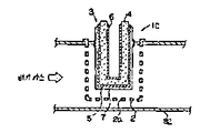
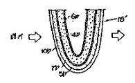
제 1 도는 내연기관이 공연비 제어에 사용되는 종래의 산소 센서의 일예를 도시하며, 산소 센서(1c)는 엔진에 접속된 배기 통로(32)내에 삽입 고정된 보호관(2)과, 그 보호관(2)내에 수용된 산소 검출 소자(3)로 구성된다. 보호관(2)의 전체면에는 피검출 가스, 즉 배기 가스를 통과시키기 위한 작은 구멍(2a)이 다수 형성되어 있다. 한편, 산소 검출 소자(3)를 예를들어 산소 이온 전도성 고체 전해질(4)과, 이 고체 전해질(4)의 양측을 끼는 전극(5,6)과, 또 이들 전극(5,6)중 피검출 가스에 접촉하는 측의 전극(5)의 표면에 형성한 보호층(7)으로 구성되고, 고체 전해질(4)로서는 투과성을 갖는 다공질 백금(Pt)등이, 보호등(7)으로서는 스피낼 등의 다공질 세라믹스가 각각 일반적으로 사용되고 있다.1 shows an example of a conventional oxygen sensor in which an internal combustion engine is used for air-fuel ratio control, wherein the oxygen sensor 1c includes a
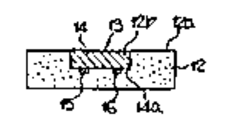
제 2 도 및 제 3 도는 종래의 다른 산소 센서의 구성을 도시하며, 산소 센서(11c)는 예를들어 알루미나 등으로 이루어지는 질연 지지체(12)와, 이 절연 지지체(12)내에 배치된 산소 농도 검출 소자(13)로 구성된다. 이 산소 농도 검출 소자(13)는 지지체(12)의 한쪽 측면(12a)에 형성된 사각형 요부(12b)에 한쪽면이 노출하도록 배치된 칩(14)과, 그 칩(14)의 배면(14a)에 접속되고, 이 내부 전기 저항의 변화를 검출하기 위한 한쌍의 Pt전극(15,16)으로 구성된다. 이 칩(14)은 예를들어 산화티탄(TiO2; 이하 티타니아라 함)등, 산소와 접촉함으로써 이 산호 농도에 따라 내부의 전기 저항이 변화하는 물질로 형성되어 있다.2 and 3 show the structure of another conventional oxygen sensor, wherein the oxygen sensor 11c is, for example, a
전극(15,16)은 출력 단자(19), 접지 단자(20)에 각각 접속되어 있다. 한편, 티타니아는 온도에 의해서도 그 내부 저항이 변화하기 때문에 주위의 온도에 의해 산소 농도 검출치가 영향받지 않도록 소정 온도로 유지할 필요가 있다. 거기서, 칩(14) 부근에는 그 칩을 소정 온도, 구체적으로는 배기 가스의 온도보다 고온으로 유지하기 위한 히터(17)가 배치되고, 그 히터(17)는 전원 단자(18), 접지 단자(20)에 각각 접속되어 있다. 이와같은 산소 센서(11c)가 엔진의 배기 통로(32)내에 예를들면 밀폐부재(23)를 거쳐 부착되어 있다.The
이와같은 종래의 산소 센서는 제 4 도에 도시한 구성의 공연비 제어 장치에 사용되고 있다. 즉, 공연비 제어 장치는 내연기관(31)의 배기 통로(32)의 3원 촉매(33)의 상류측에 배치되고, 예를들면 제 1 도에 도시한 타입의 산소 센서(1c)와, 내연기관(31)의 흡기 통로(34)에 배치된 연료 분사 밸브(35)와, 전자 제어 장치(ECU)(36)로 구성된다. 이 전자 제어 장치(36)는 산소 센서(1c)와 전기적으로 접속되고, 산소 센서(1c)가 출력하는 산소 농도 검출 신호에 따라 연료 분사 밸브(35)의 연료 분사량을 제어한다. 또 전자 제어 장치(36)의 입력측에는 도시하지 않은 드로틀 개방도 센서 크랭크 각도 위치 센서, 엔진 수온 센서, 기타 엔진 운전 변수를 검출하는 센서가 각각 전기적으로 접속되어 있다.Such a conventional oxygen sensor is used for an air-fuel ratio control device having the configuration shown in FIG. That is, the air-fuel ratio control device is disposed upstream of the three-way catalyst 33 of the
이러한 종래의 산소 센서를 사용한 공연비 제어 장치에 의한 공연비 제어를 제 5 도를 참조하여 설명한다.The air-fuel ratio control by the air-fuel ratio control apparatus using such a conventional oxygen sensor is demonstrated with reference to FIG.
기관(31)에 공급되는 혼합기의 공연비 변화에 대해 배기 통로(32)로 배출되는 배기 가스의 산소 농도의 시간 변화는 제 5a 도의 실선으로 도시된다. 또, 이 도면의 산소 농도의 시간 변화는 공연비에 대응시키기 위해 편의상 산소 농도로 나타내는 대신에 공연비로 표시하고 있다.The change in time of the oxygen concentration of the exhaust gas discharged to the
이제, 공연비(A/F)가변화하여 배기 통로(32)내의 산소 농도가 예를들면 t1시점에서 연료 풍부측으로부터 연료 부족측으로 변화했다고 하자. 산소 센서(1c)는 이 공연비 변화를 t'1시점에서 검출하여 그 출력치는 제5b도에 도시한 바와같이 소정 판별치 Vx를 가로질러 강하한다. 또, 공연비가 t2인 시점에서 연료 희박측으로부터 연료 풍부측으로 변화하면 산소 센서 1c의 출력치는 t'2시점에서 다시 상기 판별치 Vx를 가로질러 상승한다. 그때, 전자 제어 장치(36)는 이 산소 센서(1c)의 출력치, 구체적으로는 판별치 Vx에 대한 센서 출력치의 변화의 방향, 판별치 Vx를 가로질러 변화한 시점으로부터의 경과 시간에 따라 연료 공급량을 증감하는 것이다. 즉, 전자 제어 장치(36)는 피이드백 제어 모드에 의해 연료 공급량 제어를 실행하고, 이 피이드백 제어 모드에 있어서 연료 분사 밸브(35)의 연료 분사 시간 T는 예를들면 다음식(1)로 계산된다.Now, it is assumed that the air-fuel ratio A / F has changed so that the oxygen concentration in the
T=TB×K1×K2×C+TD --------------(1)T = T B × K 1 × K 2 × C + T D -------------- (1)
상기 식(1)에 있어서, TB는 기본 분사 시간이며, K1은 산소 센서에 의해 검출되는 전압치 v에 따라 결정되는 피이드백 비례항 및 적분항으로 이루어지는 보정 계수, K2는 엔진 수온, 드로틀 개방도, 대기압 등에 의해 결정되는 보정 계수, TD는 전지 전압 등에 따라 결정되는 보정 계수, C는 정수이다. 제 5c 도는 상기 보정 계수치 K1의 변화를 도시하며, K1치중 비례항치는 배기 가스중의 공연비가 풍부측으로부터 희박으로 변화되었다고 판정된 경우에는 공연비를 풍부측으로 변화시키는 소정치만큼 작은 값으로, 반대로 희박측으로부터 풍부측으로 변화했다고 판정되는 경우에는 공연비를 희박측으로 변화시키는 소정치만큼 큰 값으로 각각 설정되고, 적분항치는 예를들어 소정 미소치 당 소정 기간마다(예를들어 소정 시간마다 또는 소정 회전마다) 상기 비례항치의 변화에 대응하여 감소 또는 증가시킨 값으로 설정된다.In the above formula (1), T B is the basic injection time, K 1 is a correction coefficient composed of a feedback proportional term and an integral term determined according to the voltage value v detected by the oxygen sensor, and K 2 is the engine water temperature and the throttle. The correction coefficient determined by the opening degree, atmospheric pressure, etc., T D is the correction coefficient determined according to the battery voltage, etc., and C is an integer. 5C shows the change of the correction coefficient K 1 , where the K 1 weight proportional value is a value as small as a predetermined value for changing the air-fuel ratio to the rich side when it is determined that the air-fuel ratio in the exhaust gas is changed from the rich side to the lean side. When it is determined that the change from the lean side to the rich side is set to a value as large as a predetermined value for changing the air-fuel ratio to the lean side, the integral term is, for example, every predetermined time period (e.g., every predetermined time or predetermined rotation, for example). Each value) is set to a value that is decreased or increased corresponding to the change in the proportional term.
다음에, 기관(31)의 도시하지 않은 드로틀 밸브를 급히 개방하여 예를들어 tA시점에서 가속했다고 하면, 배기 가스 중의 산소 농도가 일시적으로 대폭 증가한다. 이 일시적 증가후에 tB시점에서 실제 산소 농도가 이론 공연비에 대응하는 값을 넘어 희박측으로 변화해도 종래의 산소 센서(1c)는 그 응답 지연 등에 기인하여 여전히 연료를 증량하는 신호를 예를들어 t'B시점까지 계속 출력하고, 그 결고 제 5c 도에 도시한 바와같이 k1치는 산소 센서(1c)의 출력이 반전되는 시점 tB로부터 t'B시점까지, △t1의 기간에 걸쳐 더욱 계속 증가하고 이 결과 상기 (1)식에 표시한 연료 분사 밸브(7)의 연료 분사 시간 T가 증가하고, 과잉 연료가 엔진(31)에 공급되고 공연비가 풍부측으로 크게 이탈하는 소위 풍부 이탈이 발생한다. 이러한 풍부 이탈이 발생하면 그동안 3원 촉매(33)의 배기 가스 정화 효율이 저하하고, CO, HC의 스파이크, 소위 풍부 스파이크가 생긴다.Next, if the throttle valve (not shown) of the
상술한 종래의 산소 센서(1c)의 응답 지연은 상세는 후술하는 바와같이, 산소 센서(1c)의 백금 전극이 일시적으로 과잉한 산소 분위기에 쪼이고, 산소에 피독되는 결과 생기는 것으로, 이러한 현상은 기관(31)에 과잉 연료가 공급되어 공연비가 일시적으로 연료 풍부측으로된 경우에도 생기고, 이경우에는 백금 전극이 과잉인 CO에 쪼이고, 이 CO에 피독됨으로써 산소 센서(1c)의 응답 지연이 생긴다.The response delay of the conventional oxygen sensor 1c described above is caused as a result of the platinum electrode of the oxygen sensor 1c being temporarily subjected to excessive oxygen atmosphere and poisoned with oxygen, as will be described later in detail. This occurs even when excess fuel is supplied to 31 and the air-fuel ratio is temporarily turned to the fuel rich side. In this case, the platinum electrode is spun by excess CO, and poisoned by this CO, causing a response delay of the oxygen sensor 1c.
다음에, 본 발명의 산소 센서의 한 형태를 제 6 도를 참조하여 설명한다. 또, 도면중, 제 1 도에 도시한 종래의 산소 센서(1c)와 동일한 구성 요소에는 동일한 부호를 붙여 표시하였다.Next, one embodiment of the oxygen sensor of the present invention will be described with reference to FIG. In addition, in the figure, the same code | symbol is attached | subjected to the component same as the conventional oxygen sensor 1c shown in FIG.
본 발명의 산소 센서(1)는 산소 이온 전도성 고체 전해질(4)을 피검출 가스, 예를들면 배기 가스에 접촉하는 제1전극(5)과 표준 공기, 예를들면 대기에 접촉하는 제2전극(6)에 의해 협지하고, 또 전극(5)의 표면을 보호층(7)에 의해 피복한 구성의 산소 농도 검출 소자(3)가 보호관(2')내에 수용되어 있다. 산소 이온 전도성 고체 전해질(4)로서는 이트리아 안정화 지르코니아(YSZ)가바람직하지만, 카르시아 안정화 지르코니아라도 좋다. 전극(5,6)으로서는 백금(Pt)이 각각 사용된다. 보호층(7)은 스피넬, r-알루미나 등의 다공질 물질로 이루어지는 것이다.The
그리고, 보호관(2')과 상기 산소 농도 검출 소자(3)의 최외층 즉 보호층(7) 사이의 공간에는 산소 분압에 따라 산소를 흡착 또는 방출하는 물질을 보유한 펠릿(8)이 충전되어 있다. 이 산소 분압에 따라 산소를 흡착 또는 방출하는 물질로서는 특히 한정되는 것은 아니나, 예를들면 산화 란탄(La2O3)이나 산소 저장 물질(OSC)로서 알려져 있는 산화 셀륨(CeO2), 산화 동(CuO), 산화 니켈(NiO) 등을 들 수 있고, 그중에서도 산화 셀륨이 적합하다. 이 산소분압에 따라 산소를 흡착 또는 방출하는 물질(이하 이들을 산소 저장 물질이라 총칭한다)은 알루미나 등의 담체에 보유되고, 펠릿형으로 형성된다. 또, 알루미나 자체는 산소 저장물질을 보유하지 않아도 산소를 흡착 또는 방출하는 특성을 가지므로, 산소 저장 물질을 보유하지 않는 알루미나 입자를 이용하는 것도 가능하다. 이 경우, 알루미나 입자는 통기성이 있는 다공질 r 알루미나가 적합하게 이용되며, 흡착 표면적을 확보하기 위해 소립자인 것이 좋다. 이 펠릿(8)의 입자 직경은 보호관(2')의 작은 구멍(2a')의 직경(d)보다 크게 설정할 필요가 있다. 또, 이 펠릿(8)의 입자 직경이 너무 크면 그 펠릿(8)을 보호관(2°)내에 충전한 때에 공극이 증대하고, 배기 가스가 펠릿(8)의 표면에 충분히 접촉하지 않고 통과해버리고, 산소 저장 물질의 작용을 충분히 발휘시키는 릿이 곤란하다. 한편, 펠릿(8)의 입자 직경이 너무 작으면 보호관(2')의 작은 구멍(2a')의 구멍 직경을 상당히 작게 형성할 필요가 있으며, 제조 비용이 상승한다. 이들 점을 감안하여 펠릿(8)의 입자 직경이 결정되지만 통상 0.5 내지 2.0mm가 적합하다.In addition, the space between the protective tube 2 'and the outermost layer of the oxygen
펠릿(8)에 보유되는 산소 저장 물질의 보유량은 특히 한정되는 것은 아니나, 예를들면 CeO2의 경우, 통상, 금속 Ce로 환산하여 4 내지 80g/l로, 적합하게는 8 내지 40g/l로 설정된다. 또, 산화 동(CuO)의 경우에는 금속 Cu로 환산하여 4 내지 20g/l가 산화 란탄(La2O3)의 경우에는 금속 La로 환산하여 8 내지 40g/l가 적합한 범위이다. 상세는 후술하는 바와같이, 이들 범위의 하한치 이하에서는 산호 흡착 효과가 없고, 상한치 이상에서는 흡착량이 너무 많아 오히려 산소 센서의 응답성을 지연시키게 된다.The amount of the oxygen storage material retained in the
알루미나에 산화 셀륨을 보유시킨 펠릿(8)은 예를들어 알루미나 담체에 초산 셀륨 용액을 소정량 함침시키고, 이어서 500℃ 이상의 온도에서 구워 형성하여 제조한다.The
제7도는 본 발명에 관한 산소 센서의 다른 형태를 도시하며, 산소 센서(11)는 산소 검출 소자(3')로서 티타니아(TiO2)를 사용한 것을 제외하고는 제 6 도에 도시한 실시예와 동일한 구성으로 한 것이다. 또, 도면중 제 2 도에 도시한 종래의 산소 센서(11c)와 동일한 구성 요소에는 동일한 부호를 붙여 표시하여 이들의 상세한 설명은 생략한다.FIG. 7 shows another embodiment of the oxygen sensor according to the present invention, and the
제 7 도에 도시한 산소 센서(11)의 산소 검출 소자(3)도 제 2 도에 도시한 종래의 산소 센서(11c)도 마찬가지로 알루미나 등의 지지체(12)의 한쪽측면에 그 표면이 노출되도록 티나니아로 이루어지는 칩(14)이 매설되고, 칩(14)에는 두 곳에 예를들어 Pt(도시 않음)이 고착되어 있다. 그리고 산소 검출 소자(3)와 보고환(2') 사이에 제 6 도에 도시한 제 1 실시예와 마찬가지로 산소 저장 물질, 예를들어 CeO2를 보유한 펠릿(8)이 충전된다.Similarly, the
또, 본 발명에 관한 산소 센서에 있어서는 산소 농도 검출 소자로서 소위 선형 센서를 사용할 수도 있다.Moreover, in the oxygen sensor which concerns on this invention, what is called a linear sensor can also be used as an oxygen concentration detection element.
제 8 도는 본 발명의 또다른 형태의 산소 센서(1A)를 도시하며, 이 산소 센서(1A)는 보호층에 산소 저장 물질을 보유시키고 있다. 보다 상세하게는, 산소 센서(1A)의 이트리어 안정화 지르코니아(YSZ)로 이루어지는 산소 이온 전도성 고체 전해질층(4a)은 표면 공기, 예를들면 대기에 접촉하는 백금 전극(6a) 및 피검출 가스, 예를들어 배기 가스에 접촉하는 백금 전극(5a)에 의해 끼어 있으며, 배기 가스측 전극(5a)의 외표면에 보호층(7a)이 형성되어 있다. 보호층(7a)은 스피넬, 알루미나 등의 다공질 물질에 산소 저장 물질을 함유시킨 것이다. 산소 저장 물질로서는 전술한, 예를들면 산화 셀륨(CeO2), 산화 란탄(La2O3), 산화 동(CuO) 등을 들 수 있고, 그중에서도 산화 셀륨이 적합하다. 이 산소 저장 물질은 상기 다공질 물질중에서, 금속 단체로 환산하여 0.8 내지 16중량% 정도 함유되는 것이 바람직하고, 더욱 바람직하게는 1.6 내지 8중량%를 함유시키는 것이 좋다. 이 함유율이 0.8중량% 미만인 경우에는 첨가 효과가 별로 인정되지 않으며, 16중량%를 초과하면 보호층 전체의 내구성이 저하되는 외에, 후술하는 바와같이 산소 센서의 응답성이 오히려 악화한다. 알루미나에 산화 셀륨을 함유시킨 보호층은 예를들면 우선 알루미나졸과 초산 셀륨 혹은 염화 셀륨을 소정 중량비로 혼합하고, 전극(5a) 외표면에 도포한 다음 건조시키고, 이어서 500℃ 이상의 온도로 구워 성형함으로써 형성된다.8 shows another type of oxygen sensor 1A of the present invention, which holds an oxygen storage material in a protective layer. More specifically, the oxygen ion conductive solid electrolyte layer 4a made of the yttria stabilized zirconia (YSZ) of the oxygen sensor 1A includes a platinum electrode 6a and a gas to be detected, which contact the surface air, for example, the atmosphere. For example, it is interposed by the platinum electrode 5a which contacts exhaust gas, and the protective layer 7a is formed in the outer surface of the exhaust gas side electrode 5a. The protective layer 7a contains an oxygen storage material in a porous material such as spinel and alumina. Examples of the oxygen storage material include the above-described examples of cerium oxide (CeO 2 ), lanthanum oxide (La 2 O 3 ), copper oxide (CuO), and the like. Among them, cerium oxide is suitable. The oxygen storage material is preferably contained in the porous material in an amount of about 0.8 to 16% by weight, more preferably 1.6 to 8% by weight, in terms of metal. When this content rate is less than 0.8 weight%, the addition effect is not recognized very much, and when it exceeds 16 weight%, the durability of the whole protective layer falls but also the responsiveness of an oxygen sensor worsens as mentioned later. The protective layer containing alumina containing cerium oxide is, for example, first mixed with alumina sol and cerium acetate or cerium chloride in a predetermined weight ratio, coated on the outer surface of the electrode 5a, and then dried and baked at a temperature of 500 ° C. or higher. It is formed by.
산소 저장 물질이 보유하는 담체는 보호층이 아니어도 좋으며, 완충층이라도 좋다. 보다 구체적으로 설명하면, 제 9 도에 도시한 산소 센서(1B)는 본 발명의 또다른 실시예를 도시하고, 이 산소 센서(1B)의 산소 이온 전도성 고체 전해질층(4b)이 대기에 접촉하는 전극(6b) 및 피검출 가스에 접촉하는 전극(5b)에 의해 끼워져 있다. 피검출 가스측의 전극(5b) 외표면에는 산소 저장 물질을 함유하는 완충층(10b)이 형성되어 있다. 산소 이온 전도성 고체 전해질(4b)로서는 이트리아 안정화 지르코니아가 전극(5b,6b)으로서는 백금이 각각 사용된다. 완충층(4)에 함유되는 산소 저장 물질로서는 특히 한정되는 것은 아니나 예를들면 산화 셀륨(CeO2), 산화 란탄(La2O3), 산화 동(CuO) 등을 들 수 있고, 그중에서도 산화 셀륨이 적합하다. 그리고, 이 완충층(10b)은 상기 산소 저장 물질을 함유하는 물질을 전극(5b) 외표면에 직접 코팅함으로써 형성된다. 구체적으로 스피넬, 실리카, 알루미나 등의 내열성 무기 산화물에 산소 저장 물질을 함유시킨 것이며, 상기 산소 저장 물질의 함유량은 금속 단체로 환산하여 무기 산화물에 대해 0.8 내지 16중량% 정도로 설정하는 것이 바람직하다.The carrier held by the oxygen storage material may not be a protective layer or may be a buffer layer. More specifically, the oxygen sensor 1B shown in FIG. 9 shows another embodiment of the present invention, in which the oxygen ion conductive solid electrolyte layer 4b of the oxygen sensor 1B contacts the atmosphere. It is interposed by the electrode 6b and the electrode 5b which contacts the to-be-detected gas. On the outer surface of the electrode 5b on the side of the gas to be detected, a buffer layer 10b containing an oxygen storage material is formed. Yttria stabilized zirconia is used as the oxygen ion conductive solid electrolyte 4b, and platinum is used as the electrodes 5b and 6b, respectively. The oxygen storage material contained in the buffer layer 4 is not particularly limited, but examples thereof include cerium oxide (CeO 2 ), lanthanum oxide (La 2 O 3 ), copper oxide (CuO), and the like. Suitable. The buffer layer 10b is formed by directly coating a material containing the oxygen storage material on the outer surface of the electrode 5b. Specifically, an oxygen storage material is contained in a heat resistant inorganic oxide such as spinel, silica, alumina, and the like, and the content of the oxygen storage material is preferably set to about 0.8 to 16% by weight relative to the inorganic oxide in terms of metal.
무기 산화물로서 알루미나를 사용하는 경우, 우선 알루미나졸과 초산 셀륨 혹은 염화셀륨을 소정 중량비로 혼합하고, 전극(5b) 외표면에 도포한 다음 건조시키고 이어서 500℃ 이상의 온도에서 구워 형성한다.When alumina is used as the inorganic oxide, first, alumina sol and cerium acetate or cerium chloride are mixed in a predetermined weight ratio, applied to the outer surface of the electrode 5b, dried, and then baked to form at a temperature of 500 ° C or higher.
또, 상기 구성에 있어서 완충층(10b) 외표면을 또 스피넬, 알루미나 등으로 이루어지고 산소 확산층으로서의 기능을 갖는 피복층으로 덮어도 좋다.Moreover, in the said structure, you may cover the outer surface of the buffer layer 10b with the coating layer which consists of spinel, alumina, etc., and has a function as an oxygen diffusion layer.
또, 제 10 도는 제 9 도에 도시한 산소 센서(1B)의 전극(5b)과 완충층(10b) 사이에 보호층(7b)을 개재시킨 변형예를 도시하며, 상기 제 9 도와 동일한 구성 요소에는 동일 부호를 붙여 표시하였다. 이 산소 센서(1B')의 보호층(7b)은 산소 확산층으로서 기능하는 것으로, 통상, 스피넬, 알루미나 등으로 형성한다. 따라서, 완충층(10b)은 이 보호층(7b) 외표면에 형성되게 된다. 또, 완충층(10b)의 형성 방법으로서는, 상기와 같은 방법을 사용할 수 있다.FIG. 10 shows a modification in which the protective layer 7b is interposed between the electrode 5b and the buffer layer 10b of the oxygen sensor 1B shown in FIG. The same code | symbol was attached | subjected and shown. The protective layer 7b of this oxygen sensor 1B 'functions as an oxygen diffusion layer, and is usually formed of spinel, alumina, or the like. Thus, the buffer layer 10b is formed on the outer surface of the protective layer 7b. In addition, as the formation method of the buffer layer 10b, the method similar to the above can be used.
제 11 도 및 제 12 도는 본 발명을 소위 후막형(두꺼운 막형) 산소 센서(1c)에 적용한 형태를 도시한다. 제 11 도는 후박형 센서(1c)를 배기 통로(32)내에 배치한 상태를 도시하며, 도면에 있어서 후막형 센서(1c)는 산소 이온 전도성 고체 전해질층(40a)을 겸하는 안정화 지르코니아로 이루어지는 지지체(40)와, 지지체(40)의 한쪽 측면(40b)에 형성된 지르코니아 등으로 이루어지는 다공질 층(41)과, 상기 다공질 층(41)으로 형성된 요부(41a)에 배치된 전극(5c), 보호층(7c) 및 산소 저장물질을 함유하는 완충층(10c)와, 지지체(40)의 중공부(40c)에 배치된 전극(6c)으로 구성된다. 한쌍의 전극(5c 및 6c)은 산소 이온 전도성 고체 전해질층(40a)을 협지하고 있으며, 각각 도시하지 않은 단자에 접속되어 있다. 중공부(40c)는 표준 가스 예를들어 대신에 연통하고 있다.11 and 12 show a mode in which the present invention is applied to a so-called thick film type (thick film type) oxygen sensor 1c. 11 shows a state where the thick thin sensor 1c is disposed in the
이러한 후막형 센서(1c)에 있어서, 보호층(7c) 및 완충층(10c)으로서는 전술한 제 9 도 및 제 10 도에 도시한 산소 센서(1B, 1B')와 마찬가지로 형성할 수 있다. 그리고, 이들 보호층(7c) 및 완충층(10c)을 다공질층(41)의 요부(41a)에 매설한 구성으로 함으로써 구조적이고 고 강도가 된다. 또, 다공질 층(41)으로서 지르코니아에 알루미나를 혼합한 것을 사용하면, 기공률이 증대하는 동시에, 완충층(10c)을 구성하는 산소 저장 물질 보유 아루미나 층과의 밀착도가 향상된다는 잇점이 있다. 또, 이 실시예에 있어서는, 보호층(7c) 및 완충층(10c)을 동시에 다공질 층(41)의 요부(41a)에 매설 형성한 경우에 대해 기술하였으나, 이에 한정되는 것은 아니며, 예를들면 다공질 층(41)을 형성하지 않고, 고체 전해질 층(40a)의 표면에 직접 전극(5c), 보호층(7c) 및 완충층(10c)을 이 순서로 형성하는 구성으로 해도 좋다.In such a thick film type sensor 1c, the protective layer 7c and the buffer layer 10c can be formed in the same manner as the oxygen sensors 1B and 1B 'shown in FIGS. 9 and 10 described above. The protective layer 7c and the buffer layer 10c are embedded in the recessed portions 41a of the
제 13 도 및 제 14 도에 도시한 산소 센서(11A)는 제 7 도에 도시한 산소 센서(11)와 유사한 티타니아 센서이며, 보호막이 산소 저장 물질을 보유하는 형태의 것이다. 또, 도면중 제 7 도와 동일한 구성 요소에는 동일부호를 붙여 표시하였다.The oxygen sensor 11A shown in FIGS. 13 and 14 is a titania sensor similar to that of the
산소 센서(11A)는 알루미나 등으로 이루어지는 절연 지지체(12') 하부에 형성된 요부(12'b)내에 산소와 접촉하여 이 접촉한 산소 농도에 따라 내부 저항이 변화되는 물질로 이루어지는, 예를들어 사각형 형상의 칩(14') 및 산소 저장 물질을 보유한 다공질 층(21)이 이 순서로 배치되고, 칩(14'), 다공질 층(21) 및 전극(15,16)으로 산소 농도 검출 소자(13')가 구성되어 있다. 산소 농도에 따라 내부 저항이 변화하는 물질로서는 전술한 티타니아가 사용되고 있다. 이와같이, 지지체(12')의 요부(12'b)내에 티타니아 칩(14') 및 다공질 층(21)을 배치하고, 다공질 층(21)의 외표면과 절연 지지체(12')의 한쪽 측면(12'a)이 균일면을 이루도록 구성함으로써, 구조적으로 고강도로 하는 것이 가능하게 되며, 또 다공질 층(21)의 박리 등의 발생도 방지할 수 있게 된다. 또, 절연 지지체(12')를 다공질 알루미나 등의 다공질체로 구성하면 상기 다공질 층(21)과 지지체(12') 사이의 정박 효과에 의해 다공질 층(21)이 한층 견고하게 지지되게 된다.The oxygen sensor 11A is made of a material which contacts with oxygen in the recessed portion 12'b formed under the insulating support 12 'made of alumina or the like and whose internal resistance changes according to the contacted oxygen concentration. A chip 14 'shaped in shape and a
다공질 층(21)에 보유되는 산소저장 물질로서는 전술한 산화 셀륨(CeO2), 산화 동(CuO) 등을 들 수 있고, 그중에서도 산화셀륨이 가장 적합하다. 다공질 층(21)에 보유되는 산소 저장 물질의 보유량은 특히 한정되는 것은 아니나, 예를들면 CeO2의 경우, 통상, 금속 Ce로 환산하여 0.8 내지 16중량%로 설정된다. 이 다공질 층(21)을 예를들면 알루미나 졸과 초산 셀륨 혹은 염화 셀륨을 소정 중량비로 혼합한 것을 칩(14')의 표면에 도포한 후, 500℃ 이상의 온도에서 구워 형성한다.Examples of the oxygen storage material held in the
또한, 본 발명의 산소 센서에 있어서는, 상술한 바와같은 절연 지지체에 형성된 요부에 칩 및 다공질 층이 함께 매설된 구성으로 한정되는 것은 아니며, 절연 지지체의 요부에 칩만이 매설되어 있는 것, 혹은 절연 지지체에 요부를 형성하지 않고, 그 절연 지지체의 한쪽 표면상에 칩 및 다공질 층이 밀착 형성되어 있는 것 등이라도 좋다.In addition, the oxygen sensor of the present invention is not limited to the configuration in which the chip and the porous layer are embedded together in the recess formed in the insulating support as described above, and only the chip is embedded in the recess of the insulating support or the insulating support. The chip and the porous layer may be formed in close contact with each other on one surface of the insulating support without forming recesses in the groove.
상술한 본 발명의 여러 가지 형태의 산소 센서는 자동차용 공연비 제어 장치에 적합하게 사용된다. 이들 산소 센서가 제 4 도에 도시한 공연비 제어 장치의 종래의 산소 센서(1c) 대신에 사용되는 경우의 작용을 제 15 도를 참조하여 설명한다.Various types of oxygen sensors of the present invention described above are suitably used for an air-fuel ratio control device for automobiles. An operation when these oxygen sensors are used in place of the conventional oxygen sensor 1c of the air-fuel ratio control device shown in FIG. 4 will be described with reference to FIG.
제 15 도는 배기 통로(32)로 배출되는 배기 가스의 산소 농도 및 산소 센서의 전극 근방의 산소 농도의 각 시간 변화를 도시하며, 제 5a 도와 유사한 그래프이다. 기관(31)의 도시하지 않은 드로틀 밸브가 te 시점에서 급히 개방되어 기관(31)이 급가속되면 배기 통로(32)내의 산소 농도는 제 15 도의 실선으로 도시한 바와같이 크게 희박측으로 변화한다. 이때, 본 발명의 산소 센서의 산소 저장 물질이 배기 가스중의 산소 분압에 따라 산소를 흡착함으로써 센서의 전극부 근방의 산소 농도는 제 15 도의 파선으로 도시한 바와같이 변화하고, 전극 근방은 과잉 산소에 쪼이는 일이 없게 되며, 전극의 산소 피독이 생기지 않는다.15 is a graph similar to that of FIG. 5A, showing each time change of the oxygen concentration of the exhaust gas discharged to the
여기서 전극의 산소 피독을 설명하면, 산소 센서의 전극 근방, 보다 정확하게는 고체 전해질 층(예를들면 이트리아 안정화 지르코니아층)과, 전극층(예를들면 백금 전극층)과, 가스층의 3상 계면인 소위 3중점(Triple Point)에서는 그근방에 도달하는 O2나 CO 등의 가스 성분을 흡착하고, 흡착된 가스 성분은 활성 상태에 있어서 가까이 흡착된 가스 성분과 활발히 반응한다. 예를들면, 흡착된 산소는 그 부근에 부착된 CO와 용이하게 반응하여 CO2가 되며, 이 CO2가 탈착된다. 이때, 흡착된 산소와 CO끼리의 반응 속도는 산소가 흡착되지 않는 CO와 반응하는 속도에 비해 현저히 빠르다.Here, the oxygen poisoning of the electrode is described as the so-called three-phase interface between the electrode of the oxygen sensor, more precisely, a solid electrolyte layer (eg yttria stabilized zirconia layer), an electrode layer (eg platinum electrode layer), and a gas layer. At the triple point, gas components such as O 2 and CO that reach the vicinity are adsorbed, and the adsorbed gas component actively reacts with the gas component adsorbed near in the active state. For example, the adsorbed oxygen to readily react with the attachment in the vicinity of the CO and CO 2, the CO 2 is the desorption. At this time, the reaction rate between the adsorbed oxygen and CO is significantly faster than the rate at which the oxygen is not adsorbed with the CO.
전극이 산소에 의해 피독된 상태라 함은 상기 3중점의 흡착 가능한 장소가 산소 가스로 대략 점령되어 CO 등의 다른 가스 성분이 흡착될 여지가 없는 상태를 말한다. 종래의 산소 센서는 산소 저장 물질을 보유하는 담체를 구비하지 않으므로 전극 근방이 일시적으로 과잉으로 산소에 쪼이기 쉽고, 일단 과잉 산소에 쪼이면 3중점은 흡착된 산소에 점령되고, 그후에 CO가스가 3중점 근방에 도달해도 흡착된 산소와 치환되는데 시간이 걸린다. 즉, 산소와 CO가 치환되기 위해서는 우선 산소가 흡착되지 않는 CO와 결부되어 탈착되어야 하며, 이 반응 속도는 상술한 바와같이 시간이 걸린다. 이 때문에 종래의 산소 센서에서는 일단 산소 피독이 발생하면, 그후에 산소 농도를 정확히 검출할 수 있는 상태로 회복할 때까지 시간이 걸리게 되며, 응답성이 나쁜 원인이 되고 있었다.The state in which the electrode is poisoned by oxygen refers to a state in which the triple adsorbable place is occupied substantially by oxygen gas and there is no room for other gas components such as CO to be adsorbed. Conventional oxygen sensors do not have a carrier that holds an oxygen storage material, so the vicinity of the electrode is temporarily prone to excess oxygen, and once exposed to excess oxygen, the triple point is occupied by adsorbed oxygen, after which the CO gas is 3 Even when it reaches the midpoint, it takes time to replace the adsorbed oxygen. That is, in order for oxygen and CO to be replaced, first, the oxygen must be desorbed in conjunction with CO which is not adsorbed, and the reaction rate takes time as described above. For this reason, in the conventional oxygen sensor, once the oxygen poisoning occurs, it takes time until the oxygen concentration can be recovered to the state where the oxygen concentration can be detected accurately, which causes a poor response.
본 발명의 산소 센서는 일시적으로 과잉 산소에 쪼여도 산소 저장 물질이 배기 가스중의 산소 분압에 따라 산소를 흡착 또는 방출하므로 전극까지 과잉 산소가 도달하지 않고, 전극의 피독의 발생이 억제된다. 산소 피독이 발생하지 않으면 배기 통로내의 산소 농도가 일시적으로 과잉으로 되었다고 해도 3중점에는 CO를 흡착할 수 있는 여지가 남게 되며, 배기 가스중의 산소 농도가 풍부측으로 복귀한 경우, CO가 남은 흡착 장소에 신속히 흡착된다. 흡착된 CO는 인접 흡착 산소와 반응하여 생성물의 CO2가 탈착하고, 후속 CO를 위해 새로운 흡착 장소가 확보된다. 이리하여 3중점은 급속히 CO로 치환되고, 배기 가스중의 산소 농도 변화가 신속히 검출되게 된다.The oxygen sensor of the present invention adsorbs or releases oxygen in accordance with the partial pressure of oxygen in the exhaust gas even if it is temporarily subjected to excess oxygen, so that excess oxygen does not reach the electrode and generation of poisoning of the electrode is suppressed. If oxygen poisoning does not occur, there is room for adsorption of CO at the triple point even if the oxygen concentration in the exhaust passage is temporarily excessive. If the oxygen concentration in the exhaust gas returns to the rich side, the adsorption place where CO remains. Adsorbed quickly. The adsorbed CO reacts with adjacent adsorbed oxygen to desorb the CO 2 of the product, leaving a new adsorption site for subsequent CO. Thus, the triple point is rapidly replaced with CO, and a change in the oxygen concentration in the exhaust gas is quickly detected.
제 15 도로 돌아가서, 상술한 설명으로부터 용이하게 추고할 수 있는 바와같이 가속후의 배기 가스중의 산소 농도가 이른 공연비에 대응하는 값을 초과하여 풍부측으로 변화하면 그 변화는 짧은 시간 지연되어, 즉 △t3시간후에 검출되고 그 결과 엔진(31)에 공급되는 혼합기의 공연비를 이론 공연비 근방으로 보다 정확히 제어할 수 있고, 소위 풍부 스파이크가 생기기 어려워진다.Returning to the fifteenth degree, if the oxygen concentration in the exhaust gas after acceleration changes to the rich side beyond the value corresponding to the early air-fuel ratio, as described easily from the above description, the change is delayed for a short time, i.e.,? T It is possible to more accurately control the air-fuel ratio of the mixer detected after 3 hours and supplied as a result to the
본 발명의 산소 센서는 공연비가 일시적으로 연료 풍부측으로 크게 변화한 경우에 생기는 산소 센서의 CO 피독도 상술한 바와 같이 유효하게 방지된다. 즉, 산소 센서의 전극이 과잉이 CO에 쪼여져서 CO로 피독되고, 전극이 흡착된 CO로 일단 점령되며 그후 전극 근방에 도달하는 산소가 전극에 흡착되기 어려워진다. 그러나, 본 발명의 산소 센서는 배기 가스중의 CO 농도가 과잉으로 많아진 경우, 산소 저장 물질로부터 흡착되어 있던 산소를 일시적으로 방출하여 전극이 과잉 CO에 쪼이는 것을 유효하게 방지하는 것이다. 따라서, 제 15 도에 도시한 바와같이 본 발명의 산소 센서는 배기 통로내의 산소 농도가 tG시점에서 풍부측으로부터 희박측으로 변화하면 짧은 시간 지연으로, 즉 △t4시간후의 t'G시점에서 그 농도 변화를 검출할 수 있다.In the oxygen sensor of the present invention, CO poisoning of the oxygen sensor generated when the air-fuel ratio is temporarily changed to the fuel rich side temporarily is also effectively prevented as described above. In other words, the excess of the electrode of the oxygen sensor is decomposed into CO and poisoned with CO, and once the electrode is occupied by the adsorbed CO, it becomes difficult to adsorb oxygen to the electrode. However, the oxygen sensor of the present invention, when the concentration of CO in the exhaust gas is excessively high, temporarily releases oxygen adsorbed from the oxygen storage material to effectively prevent the electrode from being subjected to excess CO. Therefore, as shown in FIG. 15, the oxygen sensor of the present invention has a short time delay when the oxygen concentration in the exhaust passage is changed from the rich side to the lean side at time t G , that is, at time t ' G after? T 4 hours. Changes in concentration can be detected.
또, 본 발명의 산소 센서에 사용되는 산소 저장물질은 배기 가스중의 산소 농도가 이론 공연비에 대응하는 값 근방에서는 산소를 거의 흡착도 방출도 행하지 않는다. 따라서, 담체에 보유되는 산소 저장 물질의 보유량이 적량이면 정상시에 있어서의 공연비 제어에 영향을 줄 우려는 없다.In addition, the oxygen storage material used in the oxygen sensor of the present invention hardly adsorbs or releases oxygen in the vicinity of a value where the oxygen concentration in the exhaust gas corresponds to the theoretical air-fuel ratio. Therefore, if the amount of the oxygen storage material retained in the carrier is appropriate, there is no fear of affecting the air-fuel ratio control at the time of normal operation.
그러나, 산소 센서의 보호층, 완충층 내지는 펠릿에 보유시키는 산소 저장 물질의 보유량이 적량을 초과하여 너무 많은 경우에는 산소 센서의 응답성은 오히려 악화한다. 제 16 도는 산소저장 물질의 보유량이 너무 많은 경우의 산소 센서의 전극 근방의 산소 농도 변화를 도시한다. 이와같은 산소 센서에서는 전극의 산소 피독 혹은 CO 피독은 생기지 않는다. 전극 근방의 산소 농도의 시간 변화에 지연이 생기고, 구체적으로는 제 16 도에 도시한 △t5및 △t6의 시간이 제15도에 도시한 대응하는 시간보다 길어지며, 또 가속시는 원래부터 정상 운전시에 있어서도 센서의 응답성이 악화되고 공연비 제어에 있어서의 피이드 백 주기 및 진폭이 커지며, 3원 촉매의 정화 효율이 저하한다.However, if the amount of oxygen storage material retained in the protective layer, buffer layer or pellet of the oxygen sensor exceeds a proper amount, the responsiveness of the oxygen sensor is rather deteriorated. FIG. 16 shows the oxygen concentration change near the electrode of the oxygen sensor when the amount of oxygen storage material is too large. In such an oxygen sensor, oxygen poisoning or CO poisoning of the electrode does not occur. There is a delay in the time change of the oxygen concentration near the electrode, specifically, the time of Δt 5 and Δt 6 shown in FIG. 16 is longer than the corresponding time shown in FIG. Even during normal operation, the responsiveness of the sensor deteriorates, the feed back period and amplitude in air-fuel ratio control become large, and the purification efficiency of the three-way catalyst decreases.
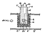
본 발명의 산소 저장 물질은 전술한 바와같이 꼭 산소 센서의 보호층, 완충층 내지는 보호관에 충전한 펠릿에 보유시킬 필요는 없고, 산소 센서와는 별개로 제 17 도에 도시한 바와같이 산소 센서의 상류에 산소 저장 물질을 보유한 모노리스(38)을 배치하게 해도 마찬가지 효과를 얻을 수 있다. 또, 제 17 도에 도시한 본 발명의 내연기관의 공연비 제어 장치의 구성 요소 중 제4도에 도시한 장치와 실질적으로 동일한 구성요소에는 도일부호를 붙여 표시하였다.As described above, the oxygen storage material of the present invention does not necessarily need to be held in pellets filled in the protective layer, the buffer layer, or the protective tube of the oxygen sensor, and is separate from the oxygen sensor, as shown in FIG. 17 upstream of the oxygen sensor. The same effect can be obtained by arranging the monolith 38 having the oxygen storage material in the. In addition, among the components of the air-fuel ratio control apparatus of the internal combustion engine of the present invention shown in FIG. 17, the same components as those shown in FIG. 4 are denoted with the same reference numerals.
본 발명의 공연비 제어 장치는 배기 통로(32)의 3원 촉매(33) 상류측에는 종래와 같은 산소 센서, 예를들면 제 1 도에 도시한 산소 센서(1c)가 배치되고, 이 산소 센서(1c)의 더욱 상류측의 배기 통로(32)에는 산소 저장 물질(OSC)을 함유하는 담체, 예를들면 OSC 보유 모노리스(38)가 배치된다.In the air-fuel ratio control device of the present invention, an oxygen sensor, such as the oxygen sensor 1c shown in FIG. 1, is arranged on the upstream side of the three-way catalyst 33 in the
3원 촉매(33)는 통상의 Pt, Rh 등을 사용한 것을 사용할 수 있고, 그 구조도 하니컴 등의 모노리스형, 혹은 펠릿형, 원통형, 구형 등의 입자형 등을 바라는 바에 따라 선택할 수 있다.As the ternary catalyst 33, one using ordinary Pt, Rh, or the like can be used, and the structure thereof can also be selected as desired such as monolith type such as honeycomb, or particle type such as pellet, cylindrical, spherical, or the like.
OSC 보유 보노리스(38)는 산소 저장 물질을 보유한 것이면 특히 한정되는 것은 아니며, 예를들면 코딜라이트에 알루미나를 주성분으로 하는 워시 코트를 실시하여 얻어진 모노리스에 산소 저장 물질을 보유해서 이루어지는 것을 사용할 수 있다. 산소 저장 물질로서는 전술한 산화 세륨(CeO2), 산화 니텔(NiO), 산화 동(CuO) 등을 들 수 있고, 그중에서 산화 셀륨이 적합하다. 산화 셀륨을 사용한 경우, Ce량으로서 10 내지 80g/l가 적합하며, 또 20 내지 60g/l가 보다 적합하다.The OSC retaining bonolith 38 is not particularly limited as long as it retains an oxygen storage material. For example, the OSC retaining bonoryris 38 may be one formed by retaining an oxygen storage material in a monolith obtained by applying a wash coat containing alumina as a main component. . Examples of the oxygen storage material include cerium oxide (CeO 2 ), nitel oxide (NiO), copper oxide (CuO), and the like, of which cerium oxide is suitable. When cerium oxide is used, 10-80 g / l is suitable as Ce amount, and 20-60 g / l is more suitable.
또, 산소 저장 물질을 보유하는 담체로서는 모노리스형에 한정되지 않고, OSC 보유 보노리스(38) 대신에 상술한 3원 촉매(33)의 경우와 마찬가지로 펠릿형, 원통, 구형 등의 입자형이라도 좋다.In addition, the carrier holding the oxygen storage material is not limited to the monolithic type, and may be a pellet type such as pellet type, cylinder, spherical shape or the like in the case of the above-described three-way catalyst 33 instead of the OSC-containing bonolith 38. .
상기 공연비 제어 장치에 따르면, 내연기관(31)으로부터의 배기 가스는 우선 OSC 보유 모노리스(38)를 통과한 후 3원 촉매(33)에 도입된다. 산소 센서(1c)는 OSC 보유 모노리스(38)을 통과 후의 배기 가스중의 산소 농도를 검출하여 그검출 신호를 전자 제어 장치(36)로 출력하게 되며 OSC 보유 모노리스(38)는 전술한 산소 센서의 산소 저장 물질을 보유한 보호층, 완충층 내지는 보호관에 충전한 펠릿과 실질적으로 같은 기능을 한다.According to the air-fuel ratio control device, the exhaust gas from the
[실시예1]Example 1
제 4 도에 도시한 공연비 제어장치의 산소 센서(1c) 대신에, 제 6 도에 도시한 산소 센서(1)를 사용하고, 그때 펠릿(8)에 보유시키는 산소 저장 물질 및 그 보유량을 여러 가지로 변화시켜 배기 가스 특성 평가 시험을 실시하였다. 산소 센서 이외의 공연비 제어 장치의 구성에 변경은 없고, 각 시험마다 3원 촉매(33)로부터 대기로 방출되는 배기 가스 성분을 측정하여 그들의 결과를 표 1에 표시하였다. 시험에 제공된 어떤 산소 센서에 대해서도 기관(31)의 운전 조건은 같으며, 기관(31)은 각 기통마다 연료 분사 밸브(35)가 배치되는 소위 다점분사(Multi Point Injection)방식의 엔진을 사용하고, 이 엔진을 LA-4 모드로 운전하여 LA-4 모드 규정의 2산째의 가속(30km/h→74km/h)시에 있어서의 CO량, HC량 및 NOx량을 구하였다.Instead of the oxygen sensor 1c of the air-fuel ratio control device shown in FIG. 4, the
또, 각 종류의 산소 센서를 각각 2개씩 준비하고 각각 2개의 산소 센서를 시험하여 얻어진 배출량을 평균하여 시험 결과로 하였다. 또, 표 1에 있어서, 각 성분의 배출량은 비교를 위해 산소 저장 물질을 보유하는 펠릿을 충전하지 않은 산소 센서, 즉 제 1 도에 도시한 종래의 산소 센서(1c)를 사용한 경우의 각 성분의 배출량을 기준(100)으로, 이와의 상대 비교치(배출 지수)가 표시되어 있다. 또, 일반적으로 엔진의 배기 가스 특성은 CO 및 미연 탄화수소(HC)가 NOx와의 배출 경향이 역 경향, 즉 한쪽 배출량이 증가하면 다른쪽은 감소한다는 경향에 있으므로, 산소 센서의 성능 비교 편의상 CO와 NOx의 배출량 상대 비교치의 승산치(CO*NOx) 및 HC가 NOx의 배출량 상대 비교치의 승산치(HC*NOx)를 표시하였다. 실제로는 얻어진 승산치를 100으로 나눈 지수가 표시되어 있다. 평가는 ◎가 개선효과 현저, ○가 효과 있음, △가 종래의 산소 센서와 비교하여 효과가 인정되지만 그 효과는 작음, ×가 개선 효과 없음을 각각 표시한다.In addition, two oxygen sensors of each type were prepared, respectively, and the discharges obtained by testing the two oxygen sensors were averaged to obtain test results. In addition, in Table 1, the discharge amount of each component is compared with each component in the case of using the oxygen sensor without filling the pellets containing the oxygen storage material, that is, the conventional oxygen sensor 1c shown in FIG. Based on the discharge amount, the relative comparison value (emission index) thereof is displayed. In general, the exhaust gas characteristics of the engine have a tendency that the emission tendency of CO and unburned hydrocarbons (HC) with NOx tends to be inverse, i.e., when one emission increases, the other tends to decrease. The multiplication value (CO * NOx) of the relative emission value of and the HC expressed the multiplication value (HC * NOx) of the relative value of the emission of NOx. In practice, an index obtained by dividing the obtained multiplication value by 100 is shown. The evaluation indicates that the improvement is remarkable, the effect is significant, and the effect is recognized as compared with the conventional oxygen sensor, but the effect is small, and x indicates no improvement.
[표 1]TABLE 1

[실시예2]Example 2
실시예 1과 같은 배기 가스 특성 평가 시험을 제 8 도에 도시한 형태의 산소 센서를 이용하여 행하고, 그들 시험 결과를 표 2에 도시한다. 시험방법, 조건, 평가 방법등은 실시예 1과 같으며, 그 설명은 생략한다.The exhaust gas characteristic evaluation test similar to Example 1 is performed using the oxygen sensor of the form shown in FIG. 8, and the test result is shown in Table 2. FIG. Test methods, conditions, evaluation methods, etc. are the same as Example 1, and the description is abbreviate | omitted.
[표 2]TABLE 2

[실시예 3]Example 3
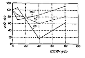
제 17 도에 도시한 OSC 보유 모노리스(38)를 구비한 공연비 제어 장치와, 이 OSC 보유 모노리스(38) 대신에 OSC를 보유하지 않을 뿐, 형상 등이 같은 OSC 비보유 모노리스를 배치한 종래의 공연비 제어 장치의 배기 가스 특성 평가 시험을 실시하고, 이들 시험 결과를 제 18 도 및 제 19 도에 도시한다. 시험은 응답성이 다른 10개의 산소 센서를 두 세트 준비하고, 각 세트의 산소 센서로 OSC 보유 모노리스에 의한 개선 효과를 조사하였다. 기타 시험 방법, 조건 등은 실시예 (1)과 같다. 제 18 도 및 제 19 도중 사선이 그어진 영역의 각 플로트는 OSC 보유 모노리스(38)를 배치한 경우, 사선이 그러지지 않은 영역의 각 플로트는 OSC 비보유 보노리스를 배치한 경우의 각 배기 가스 성분의 측정 결과이며, 산소 센서의 응답성이 다르면 엔진(31)의 배기 가스 특성이 다르긴 하지만, OSC 보유 모노리스(38)를 배치함으로써 배기 가스 특성의 향상이 현저하다는 것이 명백하다.Conventional air-fuel ratio control apparatus provided with the OSC holding monolith 38 shown in FIG. 17, and OSC non-holding monolith which does not hold an OSC instead of this OSC holding monolith 38, and has the same shape, etc. are arranged. The exhaust gas characteristic evaluation test of a control apparatus is implemented and these test results are shown in FIG. 18 and FIG. The test prepared two sets of ten oxygen sensors with different responsiveness, and investigated the improvement effect by OSC retaining monolith with each set of oxygen sensors. Other test methods, conditions, etc. are the same as Example (1). When each float of the area | region which has become oblique in the case of FIG. 18 and 19 arrange | positions the OSC holding monolith 38, each float of the area | region which does not have the diagonal line has each exhaust gas component in the case which arrange | positioned OSC non-retaining bonoris. As a result of the measurement, if the responsiveness of the oxygen sensor is different, although the exhaust gas characteristics of the
제 20 도는 마찬가지로 제 17 도에 도시한 공연비 제어 장치를 이용하고, OSC 보유 모노리스(38)의 OSC 보유량을 변화시키고, LA-4 모드 규정의 2산째 가속(30km/h→74km/h)시에 있어서의 CO, HC 및 NOx 배기량을 도시하며, 시험 결과는 OSC 보유량이 0, 즉 OSC 비보유 모노리스를 사용한 경우의 각 배기량을 100으로한 배출 지수로 표시하고 있다. OSC 보유 모노리스(38)의 OSC 보유량이 약 10 내지 80g/l의 설정범위에서 배기 가스 특성 개선 효과가 인정되고, 보유량을 20 내지 60g/l로 설정하면 가속시의 CO, HC 및 NOx 배기량은 제 18 도 및 제 19 도에 도시한 바와같이 사용하는 산소 센서의 응답성이 다르면 다르지만, 제 20 도에 도시하는 바와같이 배출 지표로 데이타를 정리하면 응답성이 다른 산소 셀서를 사용해도 거의 같은 효과가 얻어진다.FIG. 20 similarly uses the air-fuel ratio control device shown in FIG. 17 to change the OSC holding amount of the OSC holding monolith 38, and at the second acceleration (30km / h → 74km / h) of LA-4 mode regulation. CO, HC, and NOx emissions are shown, and the test results are expressed in an emission index in which the OSC reserve is 0, that is, each displacement is 100 when the OSC non-bearing monolith is used. When the OSC retention amount of the OSC retention monolith 38 is about 10 to 80 g / l, the effect of improving the exhaust gas characteristics is recognized. When the retention amount is set to 20 to 60 g / l, the CO, HC and NOx emissions during acceleration are reduced. If the responsiveness of the oxygen sensor used as shown in Figs. 18 and 19 is different, it is different. However, as shown in Fig. 20, when the data is arranged by the emission index, the effect is almost the same even when using oxygen cells having different responsiveness. Obtained.
Claims (6)
Applications Claiming Priority (21)
| Application Number | Priority Date | Filing Date | Title |
|---|---|---|---|
| JP3598587 | 1987-03-13 | ||
| JP62-35985 | 1987-03-13 | ||
| JP35985 | 1987-03-13 | ||
| JP3598687 | 1987-03-13 | ||
| JP62-35986 | 1987-03-13 | ||
| JP35986 | 1987-03-13 | ||
| JP3920287 | 1987-03-19 | ||
| JP62-39202 | 1987-03-19 | ||
| JP39202 | 1987-03-19 | ||
| JP280129 | 1987-11-05 | ||
| JP62-280129 | 1987-11-05 | ||
| JP280130 | 1987-11-05 | ||
| JP28012987 | 1987-11-05 | ||
| JP28012887 | 1987-11-05 | ||
| JP62-280130 | 1987-11-05 | ||
| JP28012787 | 1987-11-05 | ||
| JP280127 | 1987-11-05 | ||
| JP280128 | 1987-11-05 | ||
| JP28013087 | 1987-11-05 | ||
| JP62-280128 | 1987-11-05 | ||
| JP62-280127 | 1987-11-05 |
Publications (2)
| Publication Number | Publication Date |
|---|---|
| KR880011590A KR880011590A (en) | 1988-10-29 |
| KR910004223B1 true KR910004223B1 (en) | 1991-06-24 |
Family
ID=27564409
Family Applications (1)
| Application Number | Title | Priority Date | Filing Date |
|---|---|---|---|
| KR1019880002625A KR910004223B1 (en) | 1987-03-13 | 1988-03-12 | Oxigen sensor and combustion gas ratio control device engine |
Country Status (4)
| Country | Link |
|---|---|
| US (1) | US4834051A (en) |
| JP (1) | JP2797306B2 (en) |
| KR (1) | KR910004223B1 (en) |
| DE (1) | DE3807907A1 (en) |
Families Citing this family (22)
| Publication number | Priority date | Publication date | Assignee | Title |
|---|---|---|---|---|
| JPH0760141B2 (en) * | 1988-10-11 | 1995-06-28 | 株式会社日立製作所 | Air-fuel ratio controller for engine |
| DE4004172C2 (en) * | 1989-02-14 | 1998-06-04 | Ngk Spark Plug Co | An oxygen sensor for air-fuel mixture control having a protective layer comprising an oxygen occluding substance, and a method of manufacturing the sensor |
| US5232890A (en) * | 1990-01-02 | 1993-08-03 | Ganguli Partha S | Precious metal catalysts with oxygen-ion conducting support |
| CH682340A5 (en) * | 1990-04-27 | 1993-08-31 | Klaus Leistritz | |
| JP2989929B2 (en) * | 1991-05-13 | 1999-12-13 | 株式会社デンソー | Air-fuel ratio control device for internal combustion engine |
| US5268086A (en) * | 1991-08-07 | 1993-12-07 | Ford Motor Company | Catalyst monitoring using ego sensors |
| JPH06235715A (en) * | 1993-02-10 | 1994-08-23 | Toyota Motor Corp | Oxygen concentration sensor |
| DE4325183C2 (en) * | 1993-07-27 | 1995-11-23 | Roth Technik Gmbh | Oxygen sensor based on undoped cuprates |
| DE4418117C1 (en) * | 1994-05-24 | 1995-06-29 | Daimler Benz Ag | Petrol driven IC engine |
| NO310322B1 (en) * | 1999-01-11 | 2001-06-18 | Flowsys As | Painting of multiphase flow in rudder |
| DE10305856A1 (en) * | 2003-02-13 | 2004-09-02 | Robert Bosch Gmbh | sensor element |
| WO2004109252A2 (en) * | 2003-05-30 | 2004-12-16 | University Of Southern California | Oxygen sensor with a solid state reference and manufacturing thereof |
| JP2007224856A (en) * | 2006-02-24 | 2007-09-06 | Yamaha Motor Co Ltd | Control device and control method for engine |
| US20080229821A1 (en) * | 2007-03-20 | 2008-09-25 | Reeder Kevin R | Sensor impact protection apparatus |
| DE102007050119A1 (en) * | 2007-10-19 | 2009-04-23 | Robert Bosch Gmbh | Storage device, sensor element and method for the qualitative and / or quantitative determination of at least one gas component, in particular of nitrogen oxides, in a gas |
| ES2614154T3 (en) * | 2008-07-10 | 2017-05-29 | Robert Bosch Gmbh | Sensor element and procedure for determining gaseous components in gaseous mixtures and their use |
| JP5332379B2 (en) | 2008-07-28 | 2013-11-06 | オイレス工業株式会社 | Synthetic plastic thrust plain bearing |
| JP5704625B2 (en) | 2009-12-11 | 2015-04-22 | オイレス工業株式会社 | Synthetic plastic thrust plain bearing |
| US8459004B2 (en) * | 2010-10-26 | 2013-06-11 | Liang Fei Industry Co., Ltd. | Oxygen sensor bung of motor vehicle exhaust pipe |
| JP5842402B2 (en) | 2011-06-20 | 2016-01-13 | オイレス工業株式会社 | Thrust sliding bearing |
| JP6609905B2 (en) | 2014-10-27 | 2019-11-27 | オイレス工業株式会社 | Synthetic plastic plain bearing |
| JP2017089666A (en) | 2015-11-02 | 2017-05-25 | オイレス工業株式会社 | Synthetic resin-made slide bearing |
Family Cites Families (33)
| Publication number | Priority date | Publication date | Assignee | Title |
|---|---|---|---|---|
| DE2341256C3 (en) * | 1973-08-16 | 1980-08-28 | Brown, Boveri & Cie Ag, 6800 Mannheim | Measuring cell |
| US4132615A (en) * | 1974-04-05 | 1979-01-02 | Robert Bosch Gmbh | Internal combustion engine exhaust gas oxygen sensor and catalyzer combination |
| JPS5244689A (en) * | 1975-10-06 | 1977-04-07 | Toyota Motor Corp | Oxygen sensor |
| FR2354813A1 (en) * | 1976-06-17 | 1978-01-13 | Commissariat Energie Atomique | OXIDO-REDUCTION CATALYST FOR THE TREATMENT OF COMBUSTION GASES AND ITS MANUFACTURING PROCESS |
| JPS5329191A (en) * | 1976-08-31 | 1978-03-18 | Toyota Motor Co Ltd | Oxygen sensor and method of producing same |
| JPS5350888A (en) * | 1976-10-20 | 1978-05-09 | Nippon Denso Co Ltd | Oxygen concentration detector |
| US4206087A (en) * | 1977-01-06 | 1980-06-03 | Engelhard Minerals & Chemicals Corporation | Catalyst for reducing pollutants in waste gas streams and process for preparing the catalyst |
| US4080276A (en) * | 1977-04-25 | 1978-03-21 | Bendix Autolite Corporation | Gas sensor with protective coating and method of forming same |
| DE2738756A1 (en) * | 1977-08-27 | 1979-03-01 | Bbc Brown Boveri & Cie | Electrochemical cell for determining oxygen in exhaust gas - using reference electrode coated with metal oxide catalyst layer |
| JPS5853862B2 (en) * | 1978-02-20 | 1983-12-01 | 松下電器産業株式会社 | Flammable gas detection element |
| BR7902625A (en) * | 1978-05-04 | 1979-11-27 | Du Pont | IMPROVEMENT IN OXYGEN CONCENTRATION SENSOR |
| JPS584985B2 (en) * | 1978-05-10 | 1983-01-28 | 株式会社日立製作所 | gas detection element |
| JPS5590943U (en) * | 1978-12-19 | 1980-06-23 | ||
| DE2908308A1 (en) * | 1979-03-03 | 1980-09-04 | Jenaer Glaswerk Schott & Gen | MEASURING PROBE FOR DETERMINING OXYGEN PARTIAL PRESSURE IN GASES |
| JPS55166039A (en) * | 1979-06-12 | 1980-12-24 | Nissan Motor Co Ltd | Air fuel ratio detector |
| JPS55166040A (en) * | 1979-06-13 | 1980-12-24 | Nissan Motor Co Ltd | Air fuel ratio detector |
| JPS6029066B2 (en) * | 1979-07-28 | 1985-07-08 | 日産自動車株式会社 | Air-fuel ratio control signal generator |
| US4406754A (en) * | 1980-03-28 | 1983-09-27 | Kabushiki Kaisha Kobe Seiko Sho | Method and probe for the rapid determination of sulfur level |
| JPS5712002A (en) * | 1980-06-27 | 1982-01-21 | Lion Corp | Emulsifying agent for emulsion polymerization |
| JPS5754854A (en) * | 1980-09-19 | 1982-04-01 | Matsushita Electric Ind Co Ltd | Oxygen concentration detector |
| FR2494445A1 (en) * | 1980-11-17 | 1982-05-21 | Socapex | ELECTROCHEMICAL SENSOR OF SPECIES CONCENTRATIONS IN A FLUID MIXTURE AND SYSTEM FOR REGULATING THE WEALTH OF AN AIR-FUEL MIXTURE USING SUCH A SENSOR |
| US4626338A (en) * | 1981-05-01 | 1986-12-02 | Kabushiki Kaisha Toyota Chuo Kenkyusho | Equipment for detecting oxygen concentration |
| JPS59147250A (en) * | 1983-02-14 | 1984-08-23 | Fuji Electric Corp Res & Dev Ltd | Gas analyser |
| JPS59194059A (en) * | 1983-04-19 | 1984-11-02 | Toyota Motor Corp | Control method and device for air-fuel ratio and ignition timing |
| DE3322534A1 (en) * | 1983-06-23 | 1985-01-10 | Robert Bosch Gmbh, 7000 Stuttgart | RESISTANCE PROBE |
| JPS60219548A (en) * | 1984-04-16 | 1985-11-02 | Ngk Spark Plug Co Ltd | Oxygen concentration detector for exhaust gas of automobile |
| JPS60183857U (en) * | 1984-05-07 | 1985-12-06 | 株式会社デンソー | oxygen concentration detector |
| JPS60256045A (en) * | 1984-06-01 | 1985-12-17 | Nissan Motor Co Ltd | Electrode for oxygen sensor |
| JPS6179155A (en) * | 1984-09-27 | 1986-04-22 | Nissan Motor Co Ltd | Oxygen sensor element |
| JPS61241657A (en) * | 1985-04-19 | 1986-10-27 | Nissan Motor Co Ltd | Oxygen sensor element |
| JPS62245148A (en) * | 1986-04-17 | 1987-10-26 | Toyota Central Res & Dev Lab Inc | Oxygen concentration sensor |
| JPH07107524B2 (en) * | 1986-09-10 | 1995-11-15 | 日本特殊陶業株式会社 | Oxygen gas detector |
| US4773376A (en) * | 1986-11-10 | 1988-09-27 | Japan Electronic Control Systems Co., Ltd. | Oxygen gas concentration-detecting apparatus and air-fuel ratio-controlling apparatus using same in internal combustion engine |
-
1988
- 1988-03-10 DE DE3807907A patent/DE3807907A1/en active Granted
- 1988-03-10 JP JP63057011A patent/JP2797306B2/en not_active Expired - Fee Related
- 1988-03-11 US US07/166,968 patent/US4834051A/en not_active Expired - Lifetime
- 1988-03-12 KR KR1019880002625A patent/KR910004223B1/en not_active IP Right Cessation
Also Published As
| Publication number | Publication date |
|---|---|
| DE3807907C2 (en) | 1993-08-05 |
| JP2797306B2 (en) | 1998-09-17 |
| DE3807907A1 (en) | 1988-10-13 |
| JPH021532A (en) | 1990-01-05 |
| KR880011590A (en) | 1988-10-29 |
| US4834051A (en) | 1989-05-30 |
Similar Documents
| Publication | Publication Date | Title |
|---|---|---|
| KR910004223B1 (en) | Oxigen sensor and combustion gas ratio control device engine | |
| EP1074834B1 (en) | Method and apparatus for measuring NOx gas concentration | |
| KR100347643B1 (en) | Electrochemical Sensors for Determining Oxygen Concentrations in Gas Mixtures | |
| US4863583A (en) | Electrode structure of an oxygen sensing element | |
| US4306957A (en) | Device for producing control signal for feedback control of air/fuel ratio | |
| EP1760461B1 (en) | Gas sensor and method for forming same | |
| KR100355318B1 (en) | Gas sensor and its manufacturing process | |
| EP0903576B1 (en) | Gas sensor | |
| US4272349A (en) | Catalyst supported oxygen sensor with sensor element having catalyst and protective layers and a method of manufacturing same | |
| US5423973A (en) | Exhaust gas sensor and method of producing the same | |
| US8940144B2 (en) | Sensor element and method for determining gas components in gas mixtures, and use thereof | |
| US20090218220A1 (en) | Amperometric Electrochemical Cells and Sensors | |
| JP2002047919A (en) | Method for inspecting nitrogen oxide storage catalyst for working capacity | |
| EP1004877B1 (en) | Gas sensor, method of manufacturing the same, and gas sensor system using the gas sensor | |
| US20030154764A1 (en) | Sensor element operated with a preliminary catalysis | |
| JP2000310610A (en) | Gas sensor element and production thereof | |
| US4786476A (en) | Gas sensor element using porously fired mass of titania | |
| US20030121800A1 (en) | Sensor element of a gas sensor for determining gas components | |
| US6637197B1 (en) | Method for controlling a rich/lean combustion mixture in a defined manner | |
| JPS6179155A (en) | Oxygen sensor element | |
| US6942772B1 (en) | Measuring sensor for the determination of a concentration of gas constituents in gaseous mixtures | |
| JP3589872B2 (en) | Method and apparatus for detecting exhaust gas concentration | |
| EP0178149B1 (en) | Method of detecting oxygen partial pressure | |
| JPH10325824A (en) | Hydrocarbon sensor | |
| JPS6214055A (en) | Oxygen sensor |
Legal Events
| Date | Code | Title | Description |
|---|---|---|---|
| A201 | Request for examination | ||
| G160 | Decision to publish patent application | ||
| E701 | Decision to grant or registration of patent right | ||
| GRNT | Written decision to grant | ||
| FPAY | Annual fee payment |
Payment date: 20060612 Year of fee payment: 16 |
|
| LAPS | Lapse due to unpaid annual fee |