KR910002425B1 - Temperature-controlled tank container - Google Patents
Temperature-controlled tank container Download PDFInfo
- Publication number
- KR910002425B1 KR910002425B1 KR1019870014446A KR870014446A KR910002425B1 KR 910002425 B1 KR910002425 B1 KR 910002425B1 KR 1019870014446 A KR1019870014446 A KR 1019870014446A KR 870014446 A KR870014446 A KR 870014446A KR 910002425 B1 KR910002425 B1 KR 910002425B1
- Authority
- KR
- South Korea
- Prior art keywords
- tank
- rings
- container
- inner plate
- casing
- Prior art date
Links
Images


Classifications
-
- B—PERFORMING OPERATIONS; TRANSPORTING
- B61—RAILWAYS
- B61D—BODY DETAILS OR KINDS OF RAILWAY VEHICLES
- B61D5/00—Tank wagons for carrying fluent materials
- B61D5/04—Tank wagons for carrying fluent materials with means for cooling, heating, or insulating
-
- B—PERFORMING OPERATIONS; TRANSPORTING
- B65—CONVEYING; PACKING; STORING; HANDLING THIN OR FILAMENTARY MATERIAL
- B65D—CONTAINERS FOR STORAGE OR TRANSPORT OF ARTICLES OR MATERIALS, e.g. BAGS, BARRELS, BOTTLES, BOXES, CANS, CARTONS, CRATES, DRUMS, JARS, TANKS, HOPPERS, FORWARDING CONTAINERS; ACCESSORIES, CLOSURES, OR FITTINGS THEREFOR; PACKAGING ELEMENTS; PACKAGES
- B65D88/00—Large containers
- B65D88/74—Large containers having means for heating, cooling, aerating or other conditioning of contents
- B65D88/748—Large containers having means for heating, cooling, aerating or other conditioning of contents for tank containers
-
- B—PERFORMING OPERATIONS; TRANSPORTING
- B65—CONVEYING; PACKING; STORING; HANDLING THIN OR FILAMENTARY MATERIAL
- B65D—CONTAINERS FOR STORAGE OR TRANSPORT OF ARTICLES OR MATERIALS, e.g. BAGS, BARRELS, BOTTLES, BOXES, CANS, CARTONS, CRATES, DRUMS, JARS, TANKS, HOPPERS, FORWARDING CONTAINERS; ACCESSORIES, CLOSURES, OR FITTINGS THEREFOR; PACKAGING ELEMENTS; PACKAGES
- B65D88/00—Large containers
- B65D88/74—Large containers having means for heating, cooling, aerating or other conditioning of contents
- B65D88/744—Large containers having means for heating, cooling, aerating or other conditioning of contents heating or cooling through the walls or internal parts of the container, e.g. circulation of fluid inside the walls
-
- B—PERFORMING OPERATIONS; TRANSPORTING
- B65—CONVEYING; PACKING; STORING; HANDLING THIN OR FILAMENTARY MATERIAL
- B65D—CONTAINERS FOR STORAGE OR TRANSPORT OF ARTICLES OR MATERIALS, e.g. BAGS, BARRELS, BOTTLES, BOXES, CANS, CARTONS, CRATES, DRUMS, JARS, TANKS, HOPPERS, FORWARDING CONTAINERS; ACCESSORIES, CLOSURES, OR FITTINGS THEREFOR; PACKAGING ELEMENTS; PACKAGES
- B65D90/00—Component parts, details or accessories for large containers
- B65D90/02—Wall construction
- B65D90/06—Coverings, e.g. for insulating purposes
Landscapes
- Engineering & Computer Science (AREA)
- Mechanical Engineering (AREA)
- Transportation (AREA)
- Filling Or Discharging Of Gas Storage Vessels (AREA)
Abstract
내용 없음.No content.
Description
제l도는 온도 제어 탱크 컨테이너의 개략 측면도.1 is a schematic side view of a temperature controlled tank container.
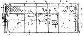
제2도는 제1도의 탱크 컨테이너의 평면도.2 is a plan view of the tank container of FIG.
제3도는 제1도 및 제2도의 탱크 컨테이너의 단부도.3 is an end view of the tank container of FIGS. 1 and 2;
제4도는 탱크 및 단열 재킷(jacket)의 축방향 부분 단면도.4 is an axial partial cross-sectional view of the tank and the thermal insulation jacket.
제5도는 탱크상에 장착된 단열 재킷의 다른 실시예를 도시하는 제4도와 유사한 축방향 단면도.5 is an axial cross-sectional view similar to FIG. 4 showing another embodiment of a thermal insulation jacket mounted on a tank.
제6도는 탱크와 단열 재킷의 내측판 및 외측판 사이에 삽입된 다른 스페이서(spacer) 부재를 도시하는 제4도와 유사한 또다른 축방향 단면도.FIG. 6 is another axial cross sectional view similar to FIG. 4 showing another spacer member inserted between the tank and the inner and outer plates of the insulating jacket.
제7도는 단열 재킷의 내측판의 장착 방법을 도시하는 상세도.7 is a detailed view showing a mounting method of the inner side plate of the heat insulation jacket.
* 도면의 주요부분에 대한 부호의 설명* Explanation of symbols for main parts of the drawings
10 : 탱크 동체 11, 12 : 바닥 부재10
13 : 보강링 14 : 단부링13: reinforcing ring 14: end ring
16 : 프레임 워크(framework) 17 : 맨홀(manhole)16: framework 17: manhole
18 : 탱크 이음쇠 19 : 오버플로우 섬프(overflow sump)18
20 : 발판 21, 22 : 구멍20:
23 : 단열재킷(jacket) 26 : 단열물질23: insulation jacket (jacket) 26: insulation material
27 : 스페이서 링(spacer ring) 29, 45 : 스페이서 부재27: spacer ring 29, 45: spacer member
30 : 간막이 웨브(partition web) 31,32,37,38,39,40,41,42 : 관통구멍30:
34 : 정부채널(vertex channel) 36 : 웨브34
43 : 이중 T형 단면 링 46 : 컵형 단열 본체43: double T-shaped cross-section ring 46: cup-shaped insulation body
47 : 보울트47: Bolt
본 발명은 온도제어 탱크 컨테이너(container)에 관한 것이며, 독일연방공화국 특허 제 2,917,364호로부터, 컨테이너 프레임워크(framework)내에 장착되고 탱크 케이싱(casing)이 정부에 마련된 탱크 이음쇠(fittings)들을 갖는 원통형 동체 및 두개의 바닥 부재들을 포함하는 탱크, 탱크를 사방에서 둘러싸며 온도제어 매체의 진입 및 배출을 위해 한쪽 단부상에 두개의 포트홀(porthole)들이 형성되어 있는 단열 재킷(jacket), 및 온도 제어 매체가 전체 탱크 둘레로 유동하도록 탱크와 재킷 사이에 배치된 간막이(partition)들로 구성된 온도 제어 탱크 컨테이너가 공지되어 있다.FIELD OF THE INVENTION The present invention relates to a temperature controlled tank container, and from a German Federal Patent No. 2,917,364, a cylindrical body having tank fittings mounted in a container framework and provided with a tank casing in the government And a tank comprising two bottom members, an insulating jacket having two ports formed on one end for enclosing the tank and entering and exiting the temperature control medium, and a temperature control medium. Temperature controlled tank containers are known which consist of partitions disposed between the tank and the jacket to flow around the entire tank.
상기 특허의 공보에서 단열 재킷이 입방체형 컨테이너 프레임워크의 평평한 벽면들상에 장착된다는 것이 중요한 특징으로 강조되었다. 이들 평평한 벽면들과 원통형 탱크 사이에는 큰 삼각유동 구역들이 형성된다.It is highlighted in the publication of this patent that the insulating jacket is mounted on the flat walls of the cube container framework. Large triangular flow zones are formed between these flat walls and the cylindrical tank.
따라서 온도 제어 매체의 많은 부분이 탱크와 접촉하지 않고 유동할 수 있으며, 이는 온도 제어 매체를 통과시키기 위한 관통 구멍들이 횡방향 격벽(bulkhead)들내에서 탱크로부터 다소 멀리 떨어지게 마련되므로 더욱 심하다.Thus, much of the temperature control medium can flow without contacting the tank, which is even worse because through-holes for passing the temperature control medium are provided some distance away from the tank in the transverse bulkheads.
또한, 공지된 탱크 컨테이너에 있어, 탱크와 단열 재킷 사이의 공간은 온도 제어 매체가 거의 탱크의 축방향으로만 유동되는 방식으로 간막이들로 분할되어 있어서, 층류(laminar flow)가 긴거리에 걸쳐서 발달할 수 있다. 간막이들의 설치에 의하여, 유동통로 길이는 탱크 길이의 2 내지 4배 이하로 얻어진다.Also, in known tank containers, the space between the tank and the insulating jacket is divided into partitions in such a way that the temperature control medium flows almost exclusively in the axial direction of the tank, so that laminar flow develops over a long distance. can do. By the installation of the diaphragms, the flow passage length is obtained to be 2 to 4 times less than the tank length.
이와같은 사실들은 온도 제어 매체가 탱크를 냉각 또는 가열하는데 사용되는 정도를 제한한다.These facts limit the extent to which the temperature control medium is used to cool or heat the tank.
또한, 단열 재킷이 컨테이너 프레임워크의 평평한 벽면을 따라 배치되어 있기 때문에, 상당히 많은 양의 단열 재료 및 덮개 재료가 필요하고, 이는 결국 전체 탱크 컨테이너의 용기 중량(tare mass)을 증가시킨다.In addition, since the insulation jacket is disposed along the flat wall of the container framework, a significant amount of insulation material and covering material is required, which in turn increases the tare mass of the entire tank container.
독일연방공화국 실용신안등록 제 7,120,959호로부터, 단열 재킷을 탱크에 대해 동심으로 상이한 반경 평면들로 연장되는 링들 사이에 배설하여, 이와같이 형성된 공간을 통하여 온도 제어 매체가 유동되도록 하는것이 공지되어 있다. 그러나, 탱크 둘레의 전체적인 매체 유동은 역시 불충분하다.From Federal Utility Model Registration No. 7,120,959, it is known that a thermal insulation jacket is arranged between the rings extending in different radial planes concentrically with respect to the tank, so that the temperature control medium flows through the space thus formed. However, the overall media flow around the tank is also insufficient.
본 발명의 목적은 온도 제어 매체를 가장 적절하게 이용하는 동시에 탱크 이음쇠들을 포함하는 탱크의 전체 둘레에 균일 유동시키는 온도 제어 탱크 컨테이너를 마련하는 것이다.It is an object of the present invention to provide a temperature controlled tank container which utilizes the temperature control medium most appropriately and at the same time uniformly flows around the entire tank including the tank fittings.
상기 목적을 이루기 위하여, 본 발명은 컨테이너 프레임워크내에 장착되고 탱크 케이싱이 정부에 마련된 탱크 이음쇠들을 갖는 원통형 동체 및 두개의 바닥 부재들을 포함하는 탱크, 전체적으로 사실상 일정 간격을 가지고 탱크 케이싱을 사방에서 둘러싸며 온도 제어 매체를 진입 및 배출시키도록 한쪽 단부에 형성된 두개의 포트홀 들을 가지고 있는 재킷, 및 탱크 케이싱과 상기 재킷 사이에 배치되고 반경방향 평면들 내에서 탱크 케이싱을 둘러싸는 다수의 간막이 링들 및 탱크의 정부선(vertex line)의 양측상에 평행하게 연장되는 두개의 간막이 웨브(web)들을 구비하는 간막이들로 구성되고, 상기 간막이 링들 및 웨브들은 상기 간막이 링들내에 형성된 관통 구멍들에 의해 서로 연통하는 구획들을 형성하여 온도 제어 매체가 탱크 이음쇠들을 둘러싸는 정부 채널(vertex channel)을 통해 탱크의 전체 길이를 따라 제1방향으로 유동하고 또한 탱크 케이싱의 모든 잔여 구역들을 통과하는 곡류형 통로(meandering path)를 따라 제2방항으로 유동하도록 하는 탱크 컨테이너를 마련한다.In order to achieve the above object, the present invention provides a tank comprising a cylindrical body and two bottom members, which are mounted in a container framework and the tank casing is provided in the government, and surrounds the tank casing from all sides at substantially regular intervals throughout. A jacket having two portholes formed at one end to enter and exit the temperature control medium, and a plurality of diaphragm rings and tanks disposed between the tank casing and the jacket and surrounding the tank casing in radial planes Two membranes extending in parallel on both sides of a vertex line consist of membranes having webs, wherein the membrane rings and the webs are partitions in communication with each other by through holes formed in the membrane rings. Forming a temperature control medium to surround the tank fittings Arrange a tank container that flows in a first direction along the entire length of the tank through a vertex channel and in a second direction along a meandering path through all remaining zones of the tank casing. do.
그러므로 온도 제어 매체는 전체 두께가 사실상 균일한 층으로 통과되며, 실제로 상기 두께는 탱크와 밀착하여 접촉하는 단지 수센티미터(cm)가 된다. 또한 단열 재킷과 탱크 사이의 균일한 작은 간격 및 유동통로의 곡류 형상은 온도 제어 매체가 계속적으로 난류(turbulence)들을 일으키도록하여, 매체의 대부분이 탱크 표면을 따라 효과적인 열교환을 위해 이용되도록 한다. 탱크가 밀접하게 둘러싸여 있기 때문에, 단열재킷에 대해 단열 및 덮개 재료가 보다 적게 소요되므로, 탱크 컨테이너의 전제 중량이 감소된다.The temperature control medium is therefore passed through a layer whose overall thickness is substantially uniform, in fact the thickness being only a few centimeters (cm) in close contact with the tank. In addition, the uniform small spacing between the thermal insulation jacket and the tank and the grain shape of the flow passages allow the temperature control medium to continuously generate turbulences, so that most of the medium is used for effective heat exchange along the tank surface. Since the tank is closely enclosed, less heat and cover material is required for the insulation jacket, thus reducing the total weight of the tank container.
적합한 실시예에 있어, 본 발명은, 단지 단부 링들을 경유하여 컨테이너 프레임워크의 단부부분들에 의해 지지되고, 이들 단부링들이 탱크와 단열 재킷사이의 공간을 세분하도록 사용된 탱크에 적용된다. 이와 같은 장치에 있어, 전체 유동 시스템내에 정부 채널을 결합하고, 또한 온도 제어 매체의 유동 통로내의 탱크 이음쇠들을 둘러싸는 오버플로우 섬프(overflow sump)를 제공하여, 오버플로우(overflow)가 상기 유동 통로에 도달하지 못하도록 하는 것이 유리하다.In a suitable embodiment, the invention is applied to a tank which is supported by the end portions of the container framework only via the end rings, which end rings are used to subdivide the space between the tank and the insulating jacket. In such a device, it provides an overflow sump that couples the government channel into the overall flow system and also surrounds the tank fittings in the flow passage of the temperature control medium, so that an overflow flows into the flow passage. It is advantageous to prevent it from reaching.
본 발명의 또다른 실시예에 있어, 정부 채널을 형성하는 간막이 웨브들은 단열 재킷 또는 단열 재킷의 내측판을 고정하는데도 사용될 수 있다.In another embodiment of the present invention, the diaphragm webs forming the government channel can also be used to secure an insulating jacket or an inner plate of the insulating jacket.
추가적인 방법들이 전체 구조를 보강하고 온도제어 매체의 유동을 원주 방향으로 제한하는 동시에 매체의 통과를 위해 유동횡단면들을 충분히 크게하도록 마련될 수 있다.Additional methods may be provided to reinforce the overall structure and limit the flow of the temperature controlled medium in the circumferential direction while at the same time making the flow cross sections large enough for the passage of the medium.
본 발명의 또다른 또는 선택적인 특징들은 단열 재킷의 외측판과 내측판 사이의 필요 간격을 얻도록 하고 또한 탱크 케이싱상에 상기 재킷을 지지하도록 한다.Another or optional feature of the invention allows to obtain the required spacing between the outer and inner plates of the insulating jacket and to support the jacket on the tank casing.
이하 본 발명의 적합한 실시예에 대하여 첨부 도면을 참조하여 상세히 기술한다.DESCRIPTION OF THE PREFERRED EMBODIMENTS Preferred embodiments of the present invention will now be described in detail with reference to the accompanying drawings.
제1도 및 제2도에 도시한 바와 같이, 탱크는 원통형 동체(10) 및 동체(10)의 양쪽 단부들에 부착된 바닥 부재들(11),(12)로 구성되며, 동체(10)은 축방향으로 격설된 다수의 보강링(13)들로 둘러싸여 있다. 바닥부재들(11),(12)는 입방형 윤곽을 갖는 외부 컨테이너 프레임워크(16)의 단부 부재(15)들상에 단부링(14)들을 관통하여 장착된다. 이와같이 프레임워크내에 단부들만에 의해 탱크를 장착하는 방법은 미합중국 특허출원 제 4,593,832호 로부터 공지되었다. 동체(10)의 상부에는 오버플로우 섬프(overflow sump)(19)내에 배치된 맨홀(manhole)(17) 및 탱크 이음쇠(18)이 갖추어져 있다. 발판(walkway)들은 제2도에 참조번호 20으로 표시되어 있다.As shown in FIGS. 1 and 2, the tank consists of a
제3도의 좌측 부분은 바닥부재(11)을 포함하는 좌측으로부터 도시한 제1도 및 제2도의 탱크 컨테이너의 단부도이나, 우측부분은 바닥부재(12)를 포함하는 제1도 및 제2도의 우측단부도이다. 바닥부재(11)은 온도 제어 매체 공급 시스템과 연결하기 위한 두개의 구멍들(21,22)가 형성되어 있다. 이와같은 공급 시스템들은 특히 컨테이너선들에 통상적이며, 온도 제어 매체는 유동율은 크나 차압(differential pressure)은 작은 경우에 유용한 정상적으로 냉각된 공기이다. 이와같은 냉각 시스템에 있어, 구멍들(21), (22)는 "포트홀(porthole)"이라는 명칭으로도 불려지며, 하부 구멍(21)은 유입 포트홀이고 상부 구멍(22)는 유출 포트홀이다. 냉각 매체의 유동은 유출 구멍(22)상에 작용하는 부압(negative pressure)에 기인한다.The left part of FIG. 3 is an end view of the tank container of FIGS. 1 and 2 shown from the left side including the
제4도의 축방향 단면도는 탱크 케이싱의 원통형 부분을 형성하는 탱크 동체(10)상에 장착된 이중 T형 단면 보강링(13)을 도시한다. 보강링(13)의 외측 플랜지는 내측판(24), 외측판(25) 및 내측판(24)와 외측판(25) 사이에 배치된 단열 물질(26)으로 구성된 단열 재킷(jacket)(23)을 지지한다. 외측판(25)는 보강링(13)과 동일한 반경방향 평면내에 배치되어 내측판(24)를 중간에 두고 보강링상에 위치한 C형 단면 스페이서 링(27)을 통해 지지된다. 보강링(13)들 사이의 구역내에서, 내측판(24)는 독특한 파형부(corrugation)(28)들 및/또는 삽입된 스페이서 부재(29)들에 의해 지지된다.The axial cross-sectional view of FIG. 4 shows a double T-shaped
탱크 동체(10)과 단열 재킷(23)의 내측판(24) 사이에 형성된 공간은, 보강링(13)들의 웨브의 높이에 의해 정해지는만큼 수센티미터(cm)정도만의 높이를 가지며, 오버플로우 섬프(19)의 폭과 원주방향으로 거의 같은 크기를 갖도록 서로 격설된 간막이 웨브(30)들에 의해 제2도에 따라 정부선의 양측에서 다시 나뉘어진다.The space formed between the
상기 간막이 웨브(30)들은 탱크동체(10)의 양족 단부에서 탱크 바닥 부재들(11),(12)와 단열 재킷(23)의 내측판(24)사이의 구역내로 연장되어 단부링(14)에서 끝난다. 양쪽 간막이 웨브(30)들 사이의 구역내에, 보강링(13)들은 관통 구멍(31)들을 가지고 있다. 이와같은 방법으로, 정부 채널(34)는 탱크 케이싱과 단열 재킷 사이에 탱크의 정상선을 따라 형성되어, 한쪽 바닥면으로부터 다른쪽 바닥면으로 축방향으로 연장된다. 제3도에 도시한 바와 같이, 오버플로우 섬프(19)의 수평 바닥부(33)들은 간막이 웨브(30)들이 오버플로우섬프(19)의 단부벽들과 계합하는 위치의 외부에, 그러므로 그 하부에, 마련된다. 그러므로, 오버플로우 섬프내에 축적된 액체가 정부 채널(34)로 들어가는 것을 지지한다.The
좌측 단부의 근처에서, 제1도 및 제2도에 도시한 바와 같이, 정부 채널(34)는 양쪽 웨브(36)들에 의해 형성된 쐐기형 구획(35)내로 연장되며, 상기 양쪽 웨브(36)들은 재킷(23)의 내측판(24)와 탱크 바닥부재(11) 사이에 삽입되고 각을 이루어 좁아져서 출구 포트홀(22)를 둘러싼다. [제3도는 상기 양쪽 웨브(36)들중의 한쪽만을 도시함]이와같은 쐐기형 구획(35)를 통하여, 정부 채널(34)는 출구 포트홀(22)내로 개방되고, 유출 포트홀(22)는 재킷(23)을 관통하며, 예컨대 컨테이너 선의 경우와 같이, 냉각 시스템과 연결되도록 칼라(co1lar)(도시생략)가 갖추어져 있다.In the vicinity of the left end, as shown in FIGS. 1 and 2, the
정부 채널(34)의 외부에, 단부링(14)들 및 보강링(13)들은 정부채널의 근처에(정부채널에 원주방향 양측에) 및 하부의 저부 구역내에 교대로 마련된 또다른 관통 구멍들(37 내지 42)가 형성되어 있다. 제1도에 도시한 바와같이, 좌측 단부링(14)내의 관통구멍(37)과 보강링(13)내의 관통 구멍들(39) 및 (41)은 정부채널(34) 근처에 배치되어 있으나, 보강링(13)들내의 관통구멍들(38) 및 (40)과 우측 단부링(14)내의 관통구멍(42)(제3도 참조)는 탱크 저부 부근에 배치되어 있다. 제3도에 도시한 바와같이, 쐐기형 구획(35) 외부에 형성되고 탱크 바닥부재(11) 및 재킷(23)의 내측판에 의해 한정된 공간은 하부 유입 구멍(21)과 통하고, 상기 하부 유입 구멍(2l)은, 유출구멍(22)와 마찬가지로, 재킷을 관통하며 상기 하부 유입 구멍(21)의 외부상에는 냉각 시스템과 연결되도록 칼라(도시생략)가 갖추어져 있다.Outside of the
여러 간막이들, 즉 보강링(13)들, 단부링(14)들, 및 간막이 웨브들(30) 및 (36)에 의하여 탱크 케이싱과 단열 재킷 사이에 형성된 구획들은 관통 구멍들(31),(32) 및 (37) 내지 (42)에 의해 서로 연통되어 있어서, 처음에 유입 구멍(21)을 통해 유입된 냉각 매체는 (제1도에 도시한 바와같이) 좌측 탱크바닥 부재를 따라 상향 유동하고, 관통 구멍(37)을 통과하여 단부링(14)와 제1보강링(13) 사이의 구역내에서 하향 유동하며, 관통구멍(38)을 통과하여 두개의 연속된 보강링(13)들 사이에 형성된 다음 구획내에서 상향 유동하고, 그다음에 하향 유동, 상향 유동, 및 다시 하향 유동하여 우측 단부링(14)내의 관통 구멍(42)를 통과한 후에, 우측 탱크 바닥 부재(12)를 따라 상향 유동하여, (제2도에 도시한 바와 같이) 단부 보강링 (14)내에 형성된 우측 관통 구멍(32)를 통하여 정부 채널(34)내로 유동하고, 정부 채널(34)내에서 오버플로우 섬프(19)를 통하여 탱크 이음쇠(18)들 및 맨홀(17)을 둘러 싸면서 축방향 좌측으로 유동하며, 마지막으로 (제2도에 도시한 바와같이) 단부링(14)의 좌측 관통구멍(32)를 통하여 및 쐐기형 구획(35)를 통하여 유출 구멍(22)로 유동한다.Several partitions, namely reinforcing
유입 구멍(21)과 우측 단부링(14)사이에서, 냉각 매체 유동은 탱크의 수직 종방향 평면의 좌우에 마련된 두 구역들로 분배되어, 각각의 상기 구역들 내에서 제1도에서 화살표들로 나타낸 곡류형 통로를 따라 유동한다.Between the
제5도에 도시한 단열 재킷(23)의 장착 방법은 제4도의 보강링(13) 및 스페이서링(27)이 탱크 케이싱용 보강링으로써 사용되는 일체로된 이중 T형 단면링(43)을 형성하도록 결합되었다는 점에서 제4도의 방법과 상이하다. 제5도에서, 상기 링(43)은 구멍들이 미리 성형되어 있으며 뒷면 붙임(back-to-back)되어 있는 두개의 C형 단면 링들로 구성된 것으로 도시되어 있다. 이와 같은 경우에, 온도 제어 매체용 관통 구멍(44)(반쪽 관통구멍으로만 도시함)는 전체 웨브 높이를 횡단하여 연장될 수 있어서 횡단면을 동일하게 유지하면서 원주 방향으로 더 좁은 구역으로 한정될 수 있다. 이는 모든 온도 제어 매체가 두개의 보강링들 사이에 형성된 각각의 구획 내에서 가능한한 원주 방향으로 유동될 수 있는 이점을 제공한다. 관통 구멍(44)에 대해 전체 웨브 높이를 사용하도록, 단열 재킷(23)의 내측판(24)는, 제5도의 좌측 부분에 도시한 바와 같이, 외측으로 절곡되어 링(43)의 외측 레그(leg)에 고정되는데 반하여, 내측판(24)의 다른쪽 부분은, 제5도의 우측부분에 도시한 바와 같이, 링(43)의 웨브의 중간부에 고정된다.The mounting method of the insulating
제6도에는 스페이서 부재(45)의 또다른 변경을 도시하며, 스페이서 부재(45)에 의해 재킷(23)의 외측판(25) 및 내측판(24)는 서로 및 탱크 동체에 대하여 격설된 관계로 고정될 수 있다. 상기 스페이서 부재(45)는 단단한 폴리우레탄 발포제, 목재, 또는 폴리에틸렌으로 제조될 수 있는 두개의 컵형 단열 본체(46)들로 되어 있으며, 상기 컵형 본체(46)들의 저부들은 내측판(24)와 계합하나 상기 컵형 본체(46)들의 연부들은 각각 탱크 동체(10) 및 외측판(25)와 계합한다. 통상적인 보울트(47)은 두개의 컵 저부들 및 내측판(24)내에 형성된 구멍(48)을 관통하며, 상기 구멍(48)의 치수는 보울트 직경보다 충분히 크다. 보울트(47)의 양쪽머리부들(보울트머리 및 너트)은 탱크 동체와 또는 외측판(25)와 모두 접촉하지 않도록 양쪽 컵 모양들 내에 들어가 있다. 양쪽 단열 본체(46)들의 컵 연부 및 컵 저부는 크라우닝(crowning)되어 있어서 탱크 및 재킷의 내측 및 외측판들의 원통형 형상이 연부들에 의하거나 또는 주름들의 형성에 의해 손상되지 않도록한다.6 shows another modification of the
조립시에, 우선 스페이서 부재(45)들은, 두개의 단열 본체(46)들이 보울트(47)에 의해 서로 죄어졌을때, 내측판(24)에 고정될 수 있다. 그 다음에, 준비된 내측판은 탱크 케이싱 둘레에 펼쳐지는데, 이 경우 반경방향 내측 단열 본체(46)들의 연부들은 접착제와 같은 것에 의하여 탱크 케이싱에 고정될 수 있다. 내측판(24)의 해제 이동은 보울트(47)과 구멍(48) 사이의 틈새에 의해 가능하다. 폴리우레탄 발포체일 수 있는 단열 물질(26)이 투여된 다음에 외측판(25)는 외측 단열 본체(46)을 가로질러 펼쳐진다.In assembly, the
이와같은 스페이서 부재(45)가 사용될때, 제4도에 도시한 스페이서 링(27)은 없어도 된다.When such a
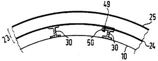
제7도에 상세히 도시한 바와 같이, 정부 채널(34)를 형성하는 간막이 웨브(30)은 상부 단부들에 플랜지(49)들을 가지고 있다. 재킷(23)의 내측판(24)는 탱크 위에 펼쳐지면 크림프 부분(crimp portion)(50)들에 의해 웨브(30)들의 플랜지(49)들 중 한쪽에 걸릴수 있다. 이와 같은 경우에 있어서 웨브(30)들은, 제7도에 도시한 바와 같이, 반경방향이나 또는 수직하게 연장될 수 있다.As shown in detail in FIG. 7, the
Claims (11)
Applications Claiming Priority (3)
| Application Number | Priority Date | Filing Date | Title |
|---|---|---|---|
| DEP3643557 | 1986-12-19 | ||
| DE19863643557 DE3643557A1 (en) | 1986-12-19 | 1986-12-19 | TEMPERATURE TANK CONTAINER |
| DE3643557.0 | 1986-12-19 |
Publications (2)
| Publication Number | Publication Date |
|---|---|
| KR880007337A KR880007337A (en) | 1988-08-26 |
| KR910002425B1 true KR910002425B1 (en) | 1991-04-22 |
Family
ID=6316658
Family Applications (1)
| Application Number | Title | Priority Date | Filing Date |
|---|---|---|---|
| KR1019870014446A KR910002425B1 (en) | 1986-12-19 | 1987-12-18 | Temperature-controlled tank container |
Country Status (11)
| Country | Link |
|---|---|
| US (1) | US4756447A (en) |
| EP (1) | EP0272494B1 (en) |
| JP (1) | JPH0613356B2 (en) |
| KR (1) | KR910002425B1 (en) |
| BR (1) | BR8706908A (en) |
| CS (1) | CS8709178A3 (en) |
| DE (1) | DE3643557A1 (en) |
| ES (1) | ES2020997B3 (en) |
| HK (1) | HK63791A (en) |
| IL (1) | IL84669A (en) |
| SG (1) | SG57991G (en) |
Families Citing this family (20)
| Publication number | Priority date | Publication date | Assignee | Title |
|---|---|---|---|---|
| DE8706579U1 (en) * | 1987-05-07 | 1988-09-08 | Westerwälder Eisenwerk Gerhard GmbH, 57586 Weitefeld | Temperature-controlled tank container |
| DE8710599U1 (en) * | 1987-08-03 | 1987-09-24 | Cassens, Holger, 2000 Hamburg | Temperature-controlled tank container |
| US4882912A (en) * | 1988-10-12 | 1989-11-28 | Container Design Limited | Temperature controllable tank container |
| DE9014104U1 (en) * | 1990-10-10 | 1992-02-06 | Westerwälder Eisenwerk Gerhard GmbH, 5241 Weitefeld | Tank container |
| US5314027A (en) * | 1993-02-12 | 1994-05-24 | Wood Donald A | Fire suppression system for a double walled storage tank |
| DE29513656U1 (en) * | 1995-08-25 | 1995-10-19 | Feldbinder & Beckmann Fahrzeugbau GmbH & Co KG, 21423 Winsen | Thermally insulated tank or silo container |
| DE29720675U1 (en) * | 1997-11-21 | 1999-04-08 | Gerhard Engineering GmbH, 57586 Weitefeld | Container tank |
| DE29816764U1 (en) * | 1998-09-18 | 2000-01-20 | GB Engineering GmbH & Co. KG, 57586 Weitefeld | Tank container |
| KR100945009B1 (en) * | 2008-03-19 | 2010-03-05 | 서울산업대학교 산학협력단 | Carrying vessel of multipurpose wagon |
| JP4707764B1 (en) | 2010-04-13 | 2011-06-22 | 八尾乳業協同組合 | Method and apparatus for preventing contamination in a fluid storage tank requiring temperature control |
| DE202010006563U1 (en) * | 2010-05-11 | 2010-09-02 | Trs Transportkoeling B.V. | Mobile tank container, equipped with a heating system |
| CN102556541B (en) * | 2012-01-11 | 2014-01-01 | 南通四方罐式储运设备制造有限公司 | Flue heating type tank container |
| US9938030B2 (en) * | 2014-12-22 | 2018-04-10 | The Nippon Synthetic Chemical Industry Co., Ltd. | Method of transporting saponified ethylene-vinyl ester-based copolymer pellets |
| US10815051B2 (en) * | 2015-06-05 | 2020-10-27 | Intermodal Sciences, Llc | Container for transport of bulk liquids using dry trailers |
| US10788269B2 (en) * | 2016-11-07 | 2020-09-29 | Wabash National, L.P. | Cooling system for mobile bulk tanks |
| CN109110320B (en) * | 2018-10-26 | 2023-09-19 | 苏州圣汇装备有限公司 | Marine low temperature fluid reservoir structure |
| RU204547U1 (en) * | 2021-02-18 | 2021-05-31 | Акционерное общество "Рузаевский завод химического машиностроения" (АО "Рузхиммаш") | Tank container |
| RU205250U1 (en) * | 2021-03-09 | 2021-07-06 | Акционерное общество "Рузаевский завод химического машиностроения" (АО "Рузхиммаш") | Tank container |
| RU205251U1 (en) * | 2021-03-09 | 2021-07-06 | Акционерное общество "Рузаевский завод химического машиностроения" (АО "Рузхиммаш") | Tank container |
| RU204634U1 (en) * | 2021-03-09 | 2021-06-02 | Акционерное общество "Рузаевский завод химического машиностроения" (АО "Рузхиммаш") | Tank container |
Family Cites Families (12)
| Publication number | Priority date | Publication date | Assignee | Title |
|---|---|---|---|---|
| US2882694A (en) * | 1956-10-05 | 1959-04-21 | Arend Peter C Vander | Cool-down apparatus for cryogenic liquid containers |
| US3157147A (en) * | 1963-05-09 | 1964-11-17 | California Research Corp | Vessel for liquefied gas |
| GB1172102A (en) * | 1967-05-26 | 1969-11-26 | A I R Air Conditioning And Ref | Thermally Insulated Container |
| FR1535681A (en) * | 1967-06-29 | 1968-08-09 | Tank container of standardized dimensions for continental transport of various liquids | |
| FR1577510A (en) * | 1968-05-17 | 1969-08-08 | ||
| DE7120959U (en) * | 1971-05-29 | 1971-11-04 | Licentia Gmbh | Heatable tank container |
| US3984994A (en) * | 1972-12-05 | 1976-10-12 | Messer Griesheim Gmbh | Process and device for filling multilayer pressure containers |
| DE2917364C2 (en) * | 1979-04-28 | 1984-01-05 | C.E.M.A.N. Special-Container Gmbh, 2000 Hamburg | Temperature controllable tank container |
| JPS56106775A (en) * | 1979-12-10 | 1981-08-25 | Transfresh Corp | Method of transporting corruptible product by continer |
| US4422274A (en) * | 1980-12-10 | 1983-12-27 | Reynolds Metals Company | Insulated panel |
| JPS589916U (en) * | 1981-07-13 | 1983-01-22 | ト−ハツ株式会社 | Cooling system for air-cooled engine for water pump |
| FI64295C (en) * | 1982-04-28 | 1983-11-10 | Santasalo Sohlberg Ab Oy | FOERVARINGSTANK FOER DESTILLERAT VATTEN |
-
1986
- 1986-12-19 DE DE19863643557 patent/DE3643557A1/en active Granted
-
1987
- 1987-11-26 EP EP87117500A patent/EP0272494B1/en not_active Expired - Lifetime
- 1987-11-26 ES ES87117500T patent/ES2020997B3/en not_active Expired - Lifetime
- 1987-12-01 IL IL84669A patent/IL84669A/en unknown
- 1987-12-14 CS CS879178A patent/CS8709178A3/en unknown
- 1987-12-15 US US07/133,337 patent/US4756447A/en not_active Expired - Fee Related
- 1987-12-18 JP JP62322657A patent/JPH0613356B2/en not_active Expired - Lifetime
- 1987-12-18 KR KR1019870014446A patent/KR910002425B1/en not_active IP Right Cessation
- 1987-12-18 BR BR8706908A patent/BR8706908A/en not_active IP Right Cessation
-
1991
- 1991-07-17 SG SG579/91A patent/SG57991G/en unknown
- 1991-08-15 HK HK637/91A patent/HK63791A/en unknown
Also Published As
| Publication number | Publication date |
|---|---|
| SG57991G (en) | 1991-08-23 |
| CS275469B2 (en) | 1992-02-19 |
| EP0272494B1 (en) | 1991-03-27 |
| JPH0613356B2 (en) | 1994-02-23 |
| KR880007337A (en) | 1988-08-26 |
| EP0272494A2 (en) | 1988-06-29 |
| ES2020997B3 (en) | 1991-10-16 |
| IL84669A (en) | 1991-06-10 |
| EP0272494A3 (en) | 1988-10-26 |
| DE3643557A1 (en) | 1988-06-23 |
| BR8706908A (en) | 1988-07-26 |
| US4756447A (en) | 1988-07-12 |
| HK63791A (en) | 1991-08-23 |
| JPS63178979A (en) | 1988-07-23 |
| CS8709178A3 (en) | 1992-02-19 |
| DE3643557C2 (en) | 1989-06-08 |
| IL84669A0 (en) | 1988-05-31 |
Similar Documents
| Publication | Publication Date | Title |
|---|---|---|
| KR910002425B1 (en) | Temperature-controlled tank container | |
| US5398889A (en) | Aircraft fuselage lining system | |
| US5545559A (en) | Compost maker | |
| US4257171A (en) | Fluidized bed gas distributor system | |
| JPH026709B2 (en) | ||
| US4478165A (en) | Ballast-cargo grid system for tankers | |
| US3990941A (en) | Nuclear reactor pressure vessel installation | |
| JPH0610023B2 (en) | Temperature controlled tank container | |
| US5899161A (en) | Ship with plane area elements which extend horizontally and are located in the hull of the ship | |
| US4104338A (en) | Bubble cap tray | |
| US3944113A (en) | Floating roof | |
| CA1089300A (en) | Refrigerated container ship with a refrigerating plant | |
| US6790357B2 (en) | Media bed support grid | |
| EP0922189B1 (en) | Rotary regenerative preheater | |
| US2916272A (en) | Column tray-structure | |
| FI67135B (en) | MEMBRANTANK | |
| KR100457880B1 (en) | Cargo containment system for LNG ship | |
| US4326920A (en) | Nuclear reactor including a reactor vessel and technique for supporting the latter | |
| KR840002351B1 (en) | Temperature tank container | |
| JPH0717671Y2 (en) | Insulation tank independent tank for liquefied gas carrier | |
| US5533463A (en) | Hull structure of nonmetallic material | |
| KR790001748B1 (en) | Load bearers for bearing solid of revolution tanks having vertical axis of revolution on board ships | |
| AU2018217864A1 (en) | Converter for converting SO2 into SO3 | |
| JPH03287485A (en) | Cooled liquid carrying vessel | |
| US4006087A (en) | Fluid distribution system |
Legal Events
| Date | Code | Title | Description |
|---|---|---|---|
| A201 | Request for examination | ||
| E902 | Notification of reason for refusal | ||
| G160 | Decision to publish patent application | ||
| E701 | Decision to grant or registration of patent right | ||
| GRNT | Written decision to grant | ||
| LAPS | Lapse due to unpaid annual fee |