KR900009131B1 - Apparatus for transferring a blank - Google Patents
Apparatus for transferring a blank Download PDFInfo
- Publication number
- KR900009131B1 KR900009131B1 KR1019840002275A KR840002275A KR900009131B1 KR 900009131 B1 KR900009131 B1 KR 900009131B1 KR 1019840002275 A KR1019840002275 A KR 1019840002275A KR 840002275 A KR840002275 A KR 840002275A KR 900009131 B1 KR900009131 B1 KR 900009131B1
- Authority
- KR
- South Korea
- Prior art keywords
- jig
- rotating arm
- horizontal
- arm
- processing material
- Prior art date
Links
Images


Classifications
-
- B—PERFORMING OPERATIONS; TRANSPORTING
- B23—MACHINE TOOLS; METAL-WORKING NOT OTHERWISE PROVIDED FOR
- B23Q—DETAILS, COMPONENTS, OR ACCESSORIES FOR MACHINE TOOLS, e.g. ARRANGEMENTS FOR COPYING OR CONTROLLING; MACHINE TOOLS IN GENERAL CHARACTERISED BY THE CONSTRUCTION OF PARTICULAR DETAILS OR COMPONENTS; COMBINATIONS OR ASSOCIATIONS OF METAL-WORKING MACHINES, NOT DIRECTED TO A PARTICULAR RESULT
- B23Q7/00—Arrangements for handling work specially combined with or arranged in, or specially adapted for use in connection with, machine tools, e.g. for conveying, loading, positioning, discharging, sorting
- B23Q7/04—Arrangements for handling work specially combined with or arranged in, or specially adapted for use in connection with, machine tools, e.g. for conveying, loading, positioning, discharging, sorting by means of grippers
Abstract
내용 없음.No content.
Description
제1도는 본 발명의 일 실시예의 치구(冶具)를 해제한 상태를 나타낸 평면도.1 is a plan view showing a state in which the jig release of an embodiment of the present invention.
제2도는 동 정면도.2 is a front view of the same.
제3도는 동 측면도.3 is the same side view.
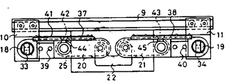
제4도는 본 발명의 일 실시예의 반전(反轉)용 치구를 장착한 상태를 나타낸 평면도.4 is a plan view showing a state in which the jig for reversal of one embodiment of the present invention is mounted.
제5도는 본 발명의 일 실시예의 이동용 치구를 장착한 상태를 나타낸 평면도.5 is a plan view showing a state in which the jig for movement of an embodiment of the present invention is mounted.
제6∼8도는 동 반전 반송 장치의 다른 상태를 각각 나타낸 정면도.6 to 8 are front views each showing another state of the inversion conveying apparatus.
제9∼11도는 동 비반전(非反轉)반송 동작의 다른 상태를 각각 나타낸 정면도.9 to 11 are front views each showing different states of the non-inverting conveyance operation.
제12도와 제13도는 브레이크의 작동을 나타낸 부분 정면도.12 and 13 are partial front views showing the operation of the brake.
* 도면의 주요부분에 대한 부호의 설명* Explanation of symbols for main parts of the drawings
1 : 본체 2 : 구동축1
4 : 종동축 5, 6 : 기어4: driven
9 : 가이드 레일 10 : 제1수평 이동 부재9: guide rail 10: first horizontal moving member
11 : 제2수평 이동 부재 12, 13 : 로울러11: second horizontal moving
18, 19 : 핀 20 : 제1회전 아암18, 19: pin 20: first rotating arm
21 : 제2회전 아암 20a, 21a : 외측 단부21:
20b, 21b : 내측 단부 25, 26 : 링크20b, 21b:
29, 30 : 요부 33, 34 : 장착부29, 30:
37, 38 : 반전용 치구 41 : 가공 재료37, 38: reverse jig 41: processing material
42 : 제1흡착기 43 : 제2흡착기42: first adsorber 43: second adsorber
48, 49 : 이동용 치구 52 : 제1흡착기48, 49: mobile jig 52: first adsorber
53 : 제2흡착기53: second adsorber
본 발명은 가공 재료 반송 장치에 관한 것으로서, 상세하게는 프레스 2차 가공 재료를 다음 프레스 가공공정을 위하여 보내는데 적합한 가공 재료 반송 장치에 관한 것이다.BACKGROUND OF THE INVENTION Field of the Invention The present invention relates to a workpiece material conveying apparatus, and in particular, to a workpiece material conveying apparatus suitable for sending a press secondary processed material for the next press working process.
선행 공정의 프레스기로부터 인출 장치에 의하여 인출된 가공 재료의 인출 종점과 후 공정의 프레스기에 공급 장치에 의하여 공급되는 가공 재료의 공급 기점과의 사이에 거리가 있는 경우에는 콘베이어등의 반송장치가 사용됨이 보통이다. 또, 가공 재료를 180도 반전시켜서 보낼 필요가 있는 경우에는, 반전 장치가 사용된다. 종래에는, 반전하지 않고 그대로 가공 재료를 반송할 경우에는, 통상의 반송 장치를 설치하고 가공 재료를 반전시켜서 반송할 경우에는 통상의 반송 장치 대신에 반전 장치를 다시 설치 하였었다. 그러므로, 하나의 프레스 가공 라인에 있어, 비반전 반송과 반전 반송이 종종 절환될 경우에는 전환 설치 작업이 번거롭고 시간도 걸렸다.When there is a distance between the withdrawal end point of the processing material drawn out by the drawing device from the pressing machine of the preceding process and the starting point of supply of the processing material supplied by the feeding device to the press machine of the subsequent process, a conveying device such as a conveyor is used. is average. Moreover, when it is necessary to invert 180 degree and send a process material, the inversion apparatus is used. Conventionally, when conveying a processing material as it is without inversion, when installing a normal conveying apparatus and inverting and conveying a processing material, the inversion apparatus was reinstalled instead of the normal conveying apparatus. Therefore, in one press working line, switching installation work is cumbersome and time-consuming when non-inverting conveyance and reverse conveyance are often switched.
본 발명의 목적은, 상술한 문제점을 해결하여 비반전 반송과 반전 반송을 치구의 개체에 의하여, 간단히 절환할 수 있는 가공 재료 반송 장치를 제공함에 있다.An object of the present invention is to solve the above-mentioned problems and to provide a workpiece material conveying apparatus which can easily switch non-inverting conveyance and reverse conveyance by an object of a jig.
이 목적을 단성하기 위하여, 본 발명은 제1회전 아암의 내측 단부와 제2회전 아암의 내측 단부를 회전가능하게 연결하여 제1회전 아암과 제2회전 아암의 외측 단부를 수평 방향으로만 이동 가능한 제1수평 이동 부재와 제2수평 이동 부재에 각각회전 가능하게 지지시키고, 제1회전 아암과 제2회전 아암에 각각 착탈 자재하게 장착되는 2개의 반전용 치구와 제1수평 이동 부재와 제 2수평 이동 부재에 각각 착탈 자재하게 장착되는 2개의 이동용 치구를 구비시키고, 전기 각 치구에 치구상의 가공 재료를 흡착하는 흡착기를 장착하고, 제1회전 아암과 제2회전 아암을 비동작시에는 수평 위치에 유지하고, 동작시에는 연결된 내측단부를 일방의 치구로부터 타방의 치구에 가공 재료가 넘어가는 수도 위치까지 인하하고, 다시 수평 위치에 되돌리는 구동력 전달 수단을 형성하고, 이로써, 반전 반송의 경우에는, 반전용 치구를 사용하고 제1회전 아암과 제2회전 아암의 90도의 하방에의 회전과 역 방향 회전과 수직 위치에서의 일방의 반전용 치구로부터 타방의 반전용 치구에의 가공 재료의 수도에 의하여 가공 재료를 180도 반전시키면서 반송하게 하며, 비반전 반송의 경우에는, 이동용 치구를 사용하여 제1회전 아암과 제2회전 아암의 90도 보다 작은 소정 각도의 하방에의 회전과 역 방향 회전과 접근 위치에서의 일방의 이동용 치구로부터 타방의 이동용 치구에의 가공 재료의 수도에 의하여 가공 재료를 이동시키도록 함을 특징으로 한다.In order to achieve this object, the present invention rotatably connects the inner end of the first rotating arm and the inner end of the second rotating arm to move the outer end of the first rotating arm and the second rotating arm only in the horizontal direction. Two reverse jig, first horizontal moving member and second horizontal support which are rotatably supported by the first horizontal moving member and the second horizontal moving member, respectively, and detachably mounted to the first rotating arm and the second rotating arm, respectively. The movable member is provided with two movable jig which are detachably attached to each of the movable members, and is equipped with an adsorber for adsorbing jig-shaped workpieces on each jig, and the first rotary arm and the second rotary arm are moved to the horizontal position when they are inoperative. During operation, the connected inner end is lowered from one jig to the other position where the processing material is passed to the other jig, and the driving force is transmitted back to the horizontal position. A stage is formed, whereby in the case of inversion conveyance, by using the inversion jig, the first rotational arm and the second rotational arm are rotated downward by 90 degrees and in one direction from the inverted jig at the vertical position. The processing material is transferred to the other reversing jig by inverting the processing material by 180 degrees. In the case of non-inverting conveying, the moving jig is used to be smaller than 90 degrees of the first rotating arm and the second rotating arm. It is characterized by moving a processing material by the number of the processing materials from one movement jig | tool to the other movement jig | tool in the rotation below and a reverse rotation and an approach position of a predetermined angle.
다음에, 본 발명을 도시한 실시예에 의하여 상세히 설명한다.Next, the present invention will be described in detail by way of examples.
제1∼3도는, 가공 재료를 유지하기 위한 반전용 치구 또는 이동용 치구를 해제한 상태를 나타낸다. 본체(1)는, 프레스기의 보울스터등에 공정된다. 프레스기의 크랭크축등의 동력원에 접속된 구동축(2)을, 본체(1)내의 베어링(3)에 의하여 회전 가능하게 지지됨과 동시에, 그 선단부는 본체(1)로부터 돌출한다. 구동축(2)에 평행으로 종동축(4)이 형성되며 기어(5), (6)에 의하여 구동력이 전달된다. 기어(6)에는 랙기어(7)가 치합하며, 랙기어(7)는, 에어 실린더(8)의 롯에 연결된다. 에어 실린더(8)는 복귀 스프링의 기능을 역할한다.1 to 3 show a state in which the reversing jig or the moving jig for holding the work material is released. The
본체(1)에는, 수평의 가이드 레일(9)이 고정되며, 가이드 레일(9)에는 제1수평 이동 부재(l0)와 제2수평 이동 부재(11)의 로울러(12), (13)가 전동 가능하게 감합한다. 이로써, 제1수평 이동 부재(10)와 제2수평 이동 부재(11)는 수평 방향으로만 이동 가능하게 안내된다. 제1수평 이동 부재(10)와 제2수평 이동 부재(11)에는 브레이크(14), (15)가 고정되며, 브레이크(14), (15)는 내장하는 브레이크 드럼(16), (17)에 마찰 접촉한다. 브레이크 드럼(16), (17)에는 핀(18), (19)이 고정된다. 이로써, 통상은 핀(18), (19)은 회전하지 않고, 제1, 2수평 이동 부재(10), (11)에 고정되어 있으나, 외부로부터 소정 이상의 회전력이 핀(18), (19)에 걸리면 브레이크(14), (15)와 브레이크 드럼(16), (17)과의 사이에 유동이 생겨서 핀(18), (19)은 회전한다.A
핀(18)에 의하여, 제1회전 아암(20)의 외측 단부(20a)가 회전 가능하게 지지된다. 마찬가지로, 핀(19)에 의하여 제2회전 아암(21)의 외측 단부(21a)가 회전 가능하게 지지된다. 제1회전 아암(20)의 내측 단부(20b)와 제2회전 아암(21)의 내측 단부(21b)는 링크(22)와 핀(23), (24)에 의하여 회전 가능하게 연결된다.By the
본체(1)로부터 전방으로 돌출하는 종동축(4}과 구동축(2)의 선단부에는 링크(25), (26)의 내측 단부가 각각이 고정되며, 링크(25), (26)의 외측 단부에는 핀(27), (28)이 각각 고정된다. 핀(27)은 제1회전 아암(20)의 중앙부에 회전 가능하게 연결되며, 핀(28)은 제2회전 아암(21)의 중앙부에 회전 가능하게 연결된다. 반전용 치구(후술)가 장착되는 요부(29), (30)가 제1회전 아암(20)과 제2회전 아암(21)에 각각 형성된다. 요부(29), (30)는, 나사 구멍(31), (32)을 갖는다. 핀(18), (19)의 선단은, 이동용 치구(후술) 가 장착되는 장착부(33), (34)로 되어 있으며, 나사 구멍(35), (36)을 갖고 있다.The inner ends of the
제4도는, 반전용 치구(37), (38)를 장착한 상태를 나타낸다. 반전용 치구(37), (38)는, 4각의 틀상의 것으로서, 나사(39), (40)(제 6 도)에 의하여 요부(29), (30)에 고정된다. 반전용 치구(37), (38)에는, 가공 재료(41)를 진공 흡착에 의하여 유지하는 제1흡착기(42)와 제2흡착기(43)가 홀더(44), (45)에 의하여 장착된다. 46,47은 가공 재료(41)를 위치 결정하는 가이드 핀으로서 인입 가능하게 장착되어 있다.4 shows a state in which the
제5도는, 이동용 치구(48), (49)를 장착한 상태를 나타낸다. 이동용 치구(48), (49)는![]()
![]()
먼저, 반전 반송 동작을 제6∼8도에 의하여 설명한다. 비동각시에는 링크(25), (26)는 제6도에 나타낸 수평 위치에 있으며, 이로써, 제1회전 아암(20)과 제2회전 아암(21)은 동일 수평면상에 있는 수평 위치에 정지하고 있다. 도시하지 않은 인출 장치의 아암이 프레스기로부터 가공 재료(41)를 인출하여 운반하여 와서 반전용 치구(37)에 얹으면 도시하지 않은 제어 장치의 제어에 의하여 제1흡착기(42)가 흡착 동작을 개시하여, 가공 재료(41)를 유지한다. 동시에, 구동축(2)이 제6도의 시계 방향으로 회전하며, 이에 따라서, 종동축(4)은 반시계 방향으로 회전한다. 따라서, 제7도에 나타낸 바와 같이 링크(25), (26)는 서로 역방향으로 회전하여 제1과 제2수평 이동 부재(10), (11)를 내측으로 향하여 이동시키면서 제1회전 아암(20)과 제2회전 아암(21)이 연결한 내측 단부(20b), (21b)를 인하한다. 구동축(2)이 90도 회전하면 제1회전 아암(20)과 제2회전 아암(21)은 제8도에 나타낸 수직 위치에 이르러 겹친 상태로 된다. 여기서, 구동축(2)의 시계 방향의 회전은 멈춘다.First, the reverse conveyance operation will be described with reference to FIGS. 6 to 8. At non-parallel, the
수직 위치에 이른 사실이 리밋 스위치(도시하지 않음)등의 센서에 의하여 검지되면, 제1흡착기(42)는 가공 재료(41)의 흡착을 해방하며, 동시에 제2흡착기(43)는 가공 재료(41)를 흡착한다. 그러므로, 가공 재료(41)는 반전용 치구(37)로부터 반전용 치구(38)로 넘어간다.When the fact of reaching the vertical position is detected by a sensor such as a limit switch (not shown), the
제8도에 나타낸 수직 외치로부터는 구동축(2)이 90도 반시계 방향으로 회전하므로 제1 및 제2회전 아암(20), (21)은 제7도의 위치를 거쳐서 제6도의 수핑 외치에 복귀한다. 이로써, 가공 재료(41)는, 제6도에 2점 점선으로 나타낸 위치에 180도 반전된 상태로 멈춘다. 이 위치에서, 제2 흡착기(43)는, 가공 재료(41)의 흡착을 해방한다.Since the
다음에, 비 반전 반송 동작을 제9∼11도에 의하여 설명한다. 구동축(2)의 시계 방향의 회전에 의하여 제1회전 아암(20)과 제2회전 아암(21)이 연결한 내측단부(20b),(21b)가 인하되어 제1 및 제2수평 이동 부재(10), (11)가 내측으로 향하여 이동하면 이동용 치규(48), (49)는 서로 접근하는 방향으로 수평 이동한다. 구동축(2)이 80도 정도의 소정 각도 회전하면 제1 및 제2회전 아암(20), (21)은 제11도에 나타낸 받아 넘기는 위치에 이르며, 이동용 치구(48), (49)는 접근하여 가공 재료(1)가 2개의 이동용 치구(48), (49)상에 등분으로 얹힌 상태로 된다. 여기서, 구동축(2)의 시계방향의 회전은 멈춘다.Next, the non-inverted conveyance operation will be described with reference to FIGS. 9 to 11. The clockwise rotation of the
받아 넘기는 위치에 이른 사실이 리밋 스위치(도시하지 않음)등의 센서에 의하여 검지되면 제1흡착기(52)는 가공 재료(41)의 흡착을 해방하며, 동시에 제2흡착기(53)는 가공 재료(41)를 흡착한다. 그러므로, 가공 재로(41)는 이동용 치구(48)로부터 이동용 치구(49)로 넘어간다.When the fact that the position is reached is detected by a sensor such as a limit switch (not shown), the
제11도에 나타낸 받아 넘기는 위치로부터는 구동축(2)이 역 회전하므로 제1 및 제2회전 아암(20), (21)은 제9도의 수평 위치에 복귀한다. 이로써, 가공 재료(41)는 제9도에 2점 점선으로 나타낸 위치에 멈춘다. 이 위치에서 제2흡착기(53)는 가공 재료(41)의 흡착을 해방한다. 이 이동거리는 제6∼8도에 나타낸 반전 반송 거리와 같다.Since the
브레이크(14), (15)는 비반전 반송시에 작동하는 것이다. 이 작동은 같은 것이므로 브레이크(14)의 작동을 제12, 13도에 의하여 설명한다. 제1회전 아암(20)이 수평 위치에 복귀한 때에 제12도에 나타낸 바와 같이, 이동용 치구(48)에 장착된 접촉편(58)이 지지부재(59)에 고정된 스토퍼(60)에 닿으므로 핀(18)에 소정 이상의 반시계 방향의 회전력이 주어져서 핀(18)은 약간 좌회전한다. 따라서, 이동용 치구(48)상에 가공 재료(41)가 얹히면 수평 이동 라인(61)에 대하여 약간 상향으로 유지된다. 이로써, 받아 넘기는 위치에서 가공재료(41)의 선단이 이동용 치구(49)에 돌출하는 일은 없다.The
제1회전 아암(21)이 제13도에 나타낸 받아 넘기는 위치까지 회전하면, 접촉편(58)이 다른 스토퍼(62)에 닿음으로써 핀(18)에 소정 이상의 시계 방향의 회전력이 주어져서 핀(18)은 약간 우회전한다. 그러므로, 가공 재료(41)의 선단은 하강하여 이동용 치구(49)의 위에 얹힌다.When the first
본 실시예에 의하면, 반전용 치구(37), (38)와 이동용 치구(48), (49)의 개체만에 의하여 반전 반송과, 비반전 반송을 절환할 수가 있으므로 절환 작업을 간단히 할 수 있고 절환 시간을 단축할 수가 있다. 또, 링크(25), (26)와 제1, 제2회전 아암(20), (21)의 회전 각도는 최대 90도이므로 동작 속도를 빨리할 수가 있다. 또한, 가동 부분의 동작은 가이드 레일(9)보다 아래에서 행해지므로 인출 장치의 아암이 치구의 위로부터 빠지기 전에 동작을 개시하여도 아암에 닿는 일이 없으며, 가공 재료(40)의 반송 시간을 단축할 수가 있다.According to the present embodiment, since the reverse conveyance and the non-invert conveyance can be switched only by the objects of the
본 실시예에 있어서, 기어(5), (6) 종동축(4)과 링크(25), (26)가 본 발명의 구동력 전달 수단에 상당한다.In this embodiment, the
본 실시예에 있어서, 제1, 제2흡착기는 가공 재료(41)가 자성체의 경우에는 전자석이어도 무방하다.In the present embodiment, the first and second adsorbers may be electromagnets when the
이상 설명한 바와 같이, 본 발명은 제1회전 아암의 내측 단부와 제2회전 아암의 내측 단부를 회전 가능하게 연결하고 제1회전 아암과 제2회전 아암의 외측 단부를 수평 방향으로만 이동 가능한 제1수평 이동부재와 제2수평 이동 부재에 각각 회전 가능하게 지지시켜서, 제1회전 아암과 제2회전 아암에 각각 착탈자재하게 장착되는, 2개의 반전용 치구와 제1수평 이동 부재와 제2수평 이동 부재에 각각 착탈 자재하게 장착되는 2개의 이동용 치구를 구비시키고 전기 각 치구에 치구상의 가공 재료를 흡착하는 흡착기를 장착하여 제1회전 아암과 제2회전 아암을 비동작시에는, 수평 위치로 유지하고, 동작시에는, 연결된 내측 단부를 일방의 치구로부터 타방의 치구에 가공 재료가 옮기는 받아 넘기는 위치까지 인하하고 재차 수평 위치에 되돌리는 구동력 전달 수단을 형성하고, 이로써, 반전 반송의 경우에는 반전용 치구를 사용하고, 제1회전 아암과 제2회전 아암의 90도의 하방에의 회전과 역방향 회전과 수직 위치에의 일방의 반전용 치구로부터 타방의 반전용 치구에의 가공 재료의 받아 넘김에 의하여 가공재료를 180도 반전시키면서 반송하도록 하며, 비반전 반송의 경우에는 이동용 치구를 사용하여 제1회전 아암과 제2회전 아암의 90도 보다 작은 소정 각도의 하방에의 회전과 역방향 회전과 접근 위치에서의 일방의 이동용 치구로부터 타방의 이동용 치구에의 가공 재료의 받아 넘김에 의하여 가공 재료를 이동시키도록 함을 특징으로 하는 것이므로 비반전 반송과 반전 반송을 치구의 개체에 의하여 간단히 절환할 수가 있다.As described above, the present invention includes a first rotatably connecting the inner end of the first rotating arm and the inner end of the second rotating arm and movable only the horizontal direction of the first rotating arm and the outer end of the second rotating arm. Two reversing jig, first horizontal moving member and second horizontal moving, which are rotatably supported on the horizontal moving member and the second horizontal moving member, respectively and detachably mounted to the first rotating arm and the second rotating arm, respectively. Each movable jig is provided with two movable jig which are detachably attached to the member, and each jig is equipped with an adsorber for absorbing jig-like workpiece material, and the first rotary arm and the second rotary arm are kept in the horizontal position when not in operation. At the time of operation, the driving force transmission is lowered from the one jig to the dripping position where the processing material is transferred from the other jig to the other jig and returned to the horizontal position again. A means is formed, whereby a reverse jig is used in the case of reverse conveyance, and the other of the first rotary arm and the second rotary arm is rotated downward by 90 degrees and reverse rotated from one reverse jig to the vertical position. The conveying of the processing material to the reversing jig of the reversal is carried out while the working material is reversed by 180 degrees, and in the case of non-inverting conveying, a predetermined smaller than 90 degrees of the first rotating arm and the second rotating arm is used by using the moving jig. Non-inverted conveyance and reverse conveyance are characterized in that the workpiece is moved by turning the workpiece from one movement jig to the other movement jig at an angle and downward rotation and in an approaching position. Can be easily switched by the jig.
Claims (1)
Applications Claiming Priority (3)
| Application Number | Priority Date | Filing Date | Title |
|---|---|---|---|
| JP58076585A JPS59201784A (en) | 1983-04-30 | 1983-04-30 | Conveyor for working material |
| JP83-76585 | 1983-04-30 | ||
| JP76585 | 1983-04-30 |
Publications (2)
| Publication Number | Publication Date |
|---|---|
| KR840008634A KR840008634A (en) | 1984-12-17 |
| KR900009131B1 true KR900009131B1 (en) | 1990-12-22 |
Family
ID=13609359
Family Applications (1)
| Application Number | Title | Priority Date | Filing Date |
|---|---|---|---|
| KR1019840002275A KR900009131B1 (en) | 1983-04-30 | 1984-04-27 | Apparatus for transferring a blank |
Country Status (2)
| Country | Link |
|---|---|
| JP (1) | JPS59201784A (en) |
| KR (1) | KR900009131B1 (en) |
Cited By (1)
| Publication number | Priority date | Publication date | Assignee | Title |
|---|---|---|---|---|
| KR20200101030A (en) * | 2019-02-19 | 2020-08-27 | 씨제이제일제당 (주) | Transperring equipment for turn arrounding product and product packaging apparatus including the same |
Families Citing this family (1)
| Publication number | Priority date | Publication date | Assignee | Title |
|---|---|---|---|---|
| JPH0230105Y2 (en) * | 1985-04-12 | 1990-08-14 |
-
1983
- 1983-04-30 JP JP58076585A patent/JPS59201784A/en active Granted
-
1984
- 1984-04-27 KR KR1019840002275A patent/KR900009131B1/en not_active IP Right Cessation
Cited By (1)
| Publication number | Priority date | Publication date | Assignee | Title |
|---|---|---|---|---|
| KR20200101030A (en) * | 2019-02-19 | 2020-08-27 | 씨제이제일제당 (주) | Transperring equipment for turn arrounding product and product packaging apparatus including the same |
Also Published As
| Publication number | Publication date |
|---|---|
| JPS59201784A (en) | 1984-11-15 |
| KR840008634A (en) | 1984-12-17 |
| JPS6362297B2 (en) | 1988-12-01 |
Similar Documents
| Publication | Publication Date | Title |
|---|---|---|
| KR100754831B1 (en) | Inversion device for printed circuit board | |
| JPH09290391A (en) | Robot | |
| KR900009131B1 (en) | Apparatus for transferring a blank | |
| EP0123478A1 (en) | Workpiece-handling apparatus | |
| US4173426A (en) | Apparatus for the automatic loading of a continuously working machine | |
| JP3356526B2 (en) | Pallet transfer device | |
| JP2001315951A (en) | Rotating device for transfer member | |
| JPS5935697B2 (en) | Pressed product reversing device | |
| JPS637482Y2 (en) | ||
| JP4282800B2 (en) | Work transfer device | |
| JPH0613811Y2 (en) | Transfer device | |
| JP3356528B2 (en) | Pallet transfer mechanism of pallet transfer device | |
| JPH0659333U (en) | Glass plate transfer device | |
| JPH087953Y2 (en) | Robot hand | |
| JPS60118440A (en) | Work gripping device | |
| JPH078123Y2 (en) | Variable stroke work transfer device | |
| SU1266732A1 (en) | Arrangement for transfer of glass workpieces on edge-working machine | |
| JPS6122897Y2 (en) | ||
| KR950010257B1 (en) | Apparatus for controlling feed-direction of three dimensional workpiece | |
| JPS6122896Y2 (en) | ||
| JPS60135192A (en) | Conveyor | |
| JP2524175Y2 (en) | Laser processing equipment | |
| JPH0738266Y2 (en) | Elevator for conveying parts with direction change function | |
| JP2001179371A (en) | Transfer-machine | |
| JPH11114763A (en) | Multiple workpiece conveying device |
Legal Events
| Date | Code | Title | Description |
|---|---|---|---|
| N231 | Notification of change of applicant | ||
| A201 | Request for examination | ||
| G160 | Decision to publish patent application | ||
| E701 | Decision to grant or registration of patent right | ||
| GRNT | Written decision to grant | ||
| FPAY | Annual fee payment |
Payment date: 19931203 Year of fee payment: 4 |
|
| LAPS | Lapse due to unpaid annual fee |