KR900007201B1 - Seal element for sealing ducts of an air conditioner system - Google Patents
Seal element for sealing ducts of an air conditioner system Download PDFInfo
- Publication number
- KR900007201B1 KR900007201B1 KR1019850009103A KR850009103A KR900007201B1 KR 900007201 B1 KR900007201 B1 KR 900007201B1 KR 1019850009103 A KR1019850009103 A KR 1019850009103A KR 850009103 A KR850009103 A KR 850009103A KR 900007201 B1 KR900007201 B1 KR 900007201B1
- Authority
- KR
- South Korea
- Prior art keywords
- main body
- pair
- foam
- seal
- arc
- Prior art date
Links
Images


Classifications
-
- B—PERFORMING OPERATIONS; TRANSPORTING
- B29—WORKING OF PLASTICS; WORKING OF SUBSTANCES IN A PLASTIC STATE IN GENERAL
- B29C—SHAPING OR JOINING OF PLASTICS; SHAPING OF MATERIAL IN A PLASTIC STATE, NOT OTHERWISE PROVIDED FOR; AFTER-TREATMENT OF THE SHAPED PRODUCTS, e.g. REPAIRING
- B29C67/00—Shaping techniques not covered by groups B29C39/00 - B29C65/00, B29C70/00 or B29C73/00
- B29C67/20—Shaping techniques not covered by groups B29C39/00 - B29C65/00, B29C70/00 or B29C73/00 for porous or cellular articles, e.g. of foam plastics, coarse-pored
-
- F—MECHANICAL ENGINEERING; LIGHTING; HEATING; WEAPONS; BLASTING
- F16—ENGINEERING ELEMENTS AND UNITS; GENERAL MEASURES FOR PRODUCING AND MAINTAINING EFFECTIVE FUNCTIONING OF MACHINES OR INSTALLATIONS; THERMAL INSULATION IN GENERAL
- F16L—PIPES; JOINTS OR FITTINGS FOR PIPES; SUPPORTS FOR PIPES, CABLES OR PROTECTIVE TUBING; MEANS FOR THERMAL INSULATION IN GENERAL
- F16L23/00—Flanged joints
- F16L23/16—Flanged joints characterised by the sealing means
- F16L23/18—Flanged joints characterised by the sealing means the sealing means being rings
-
- B—PERFORMING OPERATIONS; TRANSPORTING
- B29—WORKING OF PLASTICS; WORKING OF SUBSTANCES IN A PLASTIC STATE IN GENERAL
- B29C—SHAPING OR JOINING OF PLASTICS; SHAPING OF MATERIAL IN A PLASTIC STATE, NOT OTHERWISE PROVIDED FOR; AFTER-TREATMENT OF THE SHAPED PRODUCTS, e.g. REPAIRING
- B29C43/00—Compression moulding, i.e. applying external pressure to flow the moulding material; Apparatus therefor
- B29C43/02—Compression moulding, i.e. applying external pressure to flow the moulding material; Apparatus therefor of articles of definite length, i.e. discrete articles
-
- B—PERFORMING OPERATIONS; TRANSPORTING
- B29—WORKING OF PLASTICS; WORKING OF SUBSTANCES IN A PLASTIC STATE IN GENERAL
- B29C—SHAPING OR JOINING OF PLASTICS; SHAPING OF MATERIAL IN A PLASTIC STATE, NOT OTHERWISE PROVIDED FOR; AFTER-TREATMENT OF THE SHAPED PRODUCTS, e.g. REPAIRING
- B29C59/00—Surface shaping of articles, e.g. embossing; Apparatus therefor
- B29C59/007—Forming single grooves or ribs, e.g. tear lines, weak spots
-
- F—MECHANICAL ENGINEERING; LIGHTING; HEATING; WEAPONS; BLASTING
- F16—ENGINEERING ELEMENTS AND UNITS; GENERAL MEASURES FOR PRODUCING AND MAINTAINING EFFECTIVE FUNCTIONING OF MACHINES OR INSTALLATIONS; THERMAL INSULATION IN GENERAL
- F16J—PISTONS; CYLINDERS; SEALINGS
- F16J15/00—Sealings
- F16J15/02—Sealings between relatively-stationary surfaces
- F16J15/021—Sealings between relatively-stationary surfaces with elastic packing
- F16J15/022—Sealings between relatively-stationary surfaces with elastic packing characterised by structure or material
-
- F—MECHANICAL ENGINEERING; LIGHTING; HEATING; WEAPONS; BLASTING
- F16—ENGINEERING ELEMENTS AND UNITS; GENERAL MEASURES FOR PRODUCING AND MAINTAINING EFFECTIVE FUNCTIONING OF MACHINES OR INSTALLATIONS; THERMAL INSULATION IN GENERAL
- F16J—PISTONS; CYLINDERS; SEALINGS
- F16J15/00—Sealings
- F16J15/02—Sealings between relatively-stationary surfaces
- F16J15/06—Sealings between relatively-stationary surfaces with solid packing compressed between sealing surfaces
- F16J15/10—Sealings between relatively-stationary surfaces with solid packing compressed between sealing surfaces with non-metallic packing
- F16J15/108—Special methods for making a non-metallic packing
-
- F—MECHANICAL ENGINEERING; LIGHTING; HEATING; WEAPONS; BLASTING
- F16—ENGINEERING ELEMENTS AND UNITS; GENERAL MEASURES FOR PRODUCING AND MAINTAINING EFFECTIVE FUNCTIONING OF MACHINES OR INSTALLATIONS; THERMAL INSULATION IN GENERAL
- F16J—PISTONS; CYLINDERS; SEALINGS
- F16J15/00—Sealings
- F16J15/02—Sealings between relatively-stationary surfaces
- F16J15/14—Sealings between relatively-stationary surfaces by means of granular or plastic material, or fluid
-
- B—PERFORMING OPERATIONS; TRANSPORTING
- B29—WORKING OF PLASTICS; WORKING OF SUBSTANCES IN A PLASTIC STATE IN GENERAL
- B29K—INDEXING SCHEME ASSOCIATED WITH SUBCLASSES B29B, B29C OR B29D, RELATING TO MOULDING MATERIALS OR TO MATERIALS FOR MOULDS, REINFORCEMENTS, FILLERS OR PREFORMED PARTS, e.g. INSERTS
- B29K2105/00—Condition, form or state of moulded material or of the material to be shaped
- B29K2105/04—Condition, form or state of moulded material or of the material to be shaped cellular or porous
- B29K2105/043—Skinned foam
-
- B—PERFORMING OPERATIONS; TRANSPORTING
- B29—WORKING OF PLASTICS; WORKING OF SUBSTANCES IN A PLASTIC STATE IN GENERAL
- B29K—INDEXING SCHEME ASSOCIATED WITH SUBCLASSES B29B, B29C OR B29D, RELATING TO MOULDING MATERIALS OR TO MATERIALS FOR MOULDS, REINFORCEMENTS, FILLERS OR PREFORMED PARTS, e.g. INSERTS
- B29K2105/00—Condition, form or state of moulded material or of the material to be shaped
- B29K2105/04—Condition, form or state of moulded material or of the material to be shaped cellular or porous
- B29K2105/045—Condition, form or state of moulded material or of the material to be shaped cellular or porous with open cells
-
- B—PERFORMING OPERATIONS; TRANSPORTING
- B29—WORKING OF PLASTICS; WORKING OF SUBSTANCES IN A PLASTIC STATE IN GENERAL
- B29K—INDEXING SCHEME ASSOCIATED WITH SUBCLASSES B29B, B29C OR B29D, RELATING TO MOULDING MATERIALS OR TO MATERIALS FOR MOULDS, REINFORCEMENTS, FILLERS OR PREFORMED PARTS, e.g. INSERTS
- B29K2105/00—Condition, form or state of moulded material or of the material to be shaped
- B29K2105/04—Condition, form or state of moulded material or of the material to be shaped cellular or porous
- B29K2105/046—Condition, form or state of moulded material or of the material to be shaped cellular or porous with closed cells
Abstract
Description
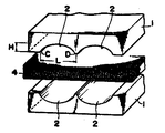
제 1 도 (a), (b)는 본 발명의 한 실시예를 나타낸 것으로,Figure 1 (a), (b) shows an embodiment of the present invention,
제 1 도 (a)는 발포시일을 가압하기 전의 상태를 나타낸 사시도.1 (a) is a perspective view showing a state before pressing the foam seal.
제 1 도 (b)는 형성된 주상체의 사시도.1B is a perspective view of the formed columnar body.
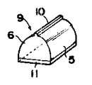
제 2 도는 위와 같은 제조방법으로 성형된 성형시일재를 나타낸 사시도.2 is a perspective view showing a molding seal material molded by the above manufacturing method.
제 3 도 (a), (b)는 본 발명의 다른 실시예를 나타낸 것으로,Figure 3 (a), (b) shows another embodiment of the present invention,
제 3 도 (a)는 발포시일을 가압하기 전의 상태를 나타낸 사시도.Figure 3 (a) is a perspective view showing a state before pressing the foam seal.
제 3 도 (b)는 형성된 주상체의 사시도.(B) is a perspective view of the columnar body formed.
제 4 도는 위와 같은 제조방법으로 성형된 성형시일재를 나타낸 사시도.4 is a perspective view showing a molding seal material molded by the manufacturing method as described above.
제 5 도 (a), (b)는 종래예를 나타낸 것으로,5 (a) and 5 (b) show a conventional example,
제 5 도 (a)는 발포시일을 가압하기 전의 상태를 나타낸 사시도.Figure 5 (a) is a perspective view showing a state before pressing the foam seal.
제 5 도 (b)는 형성된 주상체의 사시도.(B) is a perspective view of the columnar body formed.
* 도면의 주요 부분에 대한 부호의 설명* Explanation of symbols on main parts of drawing
1 : 성형틀 2 : 홈1: forming mold 2: groove
4 : 발포시이트 5 : 호상부4: foam sheet 5: arc part
6 : 본체부 7 : 연결부6: body part 7: connection part
8 : 주상체 9 : 성형시일재8 columnar body 9: molding sealing material
본 발명은 발포주상성형(發抱柱狀成形)시일재에 관한 것으로 에어시일재, 물시일재 등으로 사용되며, 특히 자동차용 공기조화(air conditioning)의 송풍장치(blower unit), 냉각장치(cooling unit), 가열장치(heater unit) 사이를 연결하는 접합부분 및 접합부재사이의 기밀성을 유지하는 시일재로서, 가장 적합한 시일재를 제공하려는 것이다.BACKGROUND OF THE INVENTION 1. Field of the Invention The present invention relates to a foam columnar sealing material and is used as an air seal material, a water seal material, and the like, and in particular, a blower unit and a cooling device of air conditioning for automobiles ( As a sealing material for maintaining the airtightness between the cooling unit, the joint portion connecting the heater (heater unit) and the bonding member, it is to provide the most suitable sealing material.
종래에는 고무 또는 합성수지 발포체로된 반원형 또는 반타원형의 시일재 그 자체는 예컨데; 일본국 실개소 48-94337호 공보에 따라 널리 알려져 있으며, 그 제조방법으로서는,Conventionally, semi-circular or semi-elliptic seal materials of rubber or synthetic resin foams themselves are, for example; It is widely known according to Japanese Patent Application Laid-Open No. 48-94337, and as a manufacturing method thereof,
(1) 가황(加黃) 전의 고무스폰지 원료를 성형틀내에 주입한 다음 열을 가하여 가하여 가황하는 방법.(1) A method of vulcanizing by injecting a rubber sponge raw material before vulcanization into a mold and then applying heat.
(2) 원료를 다이스에서 압출하는 방법.(2) A method of extruding a raw material from a die.
(3) 폴리우레탄형 등의 액상원료를 성형틀에 주입하여 성형하는 방법.(3) A method of molding by injecting a liquid raw material such as polyurethane type into a molding die.
(4) 단면이 호상(弧狀)의 홈을 지닌 성형틀을 이용하여 사용하는 발포시이트를 압축하여 성형하는 방법.(4) A method of compressing and molding a foam sheet to be used using a molding die having an arc-shaped groove in cross section.
이 알려져 있다.This is known.
그러나 (1)의 방법은 열성형시간이 길고, 또 발포가 클때에는 가황의 정도에 따라 미묘하게 변화하여 일정한 제품을 얻을 수 없는 결점이 있었다.However, the method of (1) has a drawback in that when the thermoforming time is long and the foaming is large, it is delicately changed depending on the degree of vulcanization and a constant product cannot be obtained.
(2)의 방법은 안정하나 균일한 발포체를 얻기 어렵고, 또 특히 연속기포체는 균일한 발포체를 얻기 어려워 고발포체(高發泡體)를 얻을 수 없는 결점이 있었다.Although the method of (2) is stable, it is difficult to obtain a uniform foam, and in particular, the continuous foam has a drawback in that it is difficult to obtain a uniform foam and a high foaming body cannot be obtained.
(3)의 방법은 낱낱의 금형을 필요로 하기 때문에 다량생산하려면 다수의 금형을 필요로 하여 값이 비싸게 될뿐 아니라 연속적 제조가 불가능하여 작업성도 좋지 않고 비능율적이었다. 그뿐 아니라 액상원료이기 때문에 금형온도의 작은 변화에 따라 핀홀(pin hole)이 생성한다거나 또는 표피가 벗겨진다거나 하는 결점이있었다.Since the method of (3) requires a single mold, a large number of molds require a large number of molds, which is expensive, and continuous manufacturing is not possible, resulting in poor workability and inefficiency. In addition, because it is a liquid raw material, there was a drawback that pinholes were generated or the skin was peeled off due to a small change in the mold temperature.
(4)의 방법은 제 5 도 (a), (b)에서 보는 바와 같이 발포시이트(4)를 호상의 홈(2)이 형성된 성형틀(1)과 평판상의 대판(3)와의 사이에 삽입하여 압축하면 상부면에 호상부(5)를 지닌 주상체(8)를 얻을 수 있다. 그러나 발포시이트(4)의 상부면에 호상부(5)를 형성하고, 호상부(5)의 높이(h)를 그대로 제품의 높이를 하고있다.In the method of (4), as shown in FIGS. 5A and 5B, the foam sheet 4 is inserted between the mold 1 in which the arc-
따라서, 주상체(8)의 호상부(5)의 길이가 발포시이트(4)의 상부면(4a)의 길이보다 길어지므로, 발포시이트(4)의 하부면(4b)에서 세게 당겨져서 이때문에 홈(2)의 깊이(H)를 아무리 깊이하여도 호상부(5)의 높이(h)는 제한되며, 제품의 높이가 대단히 낮아지는 결점이 있었다. 또 얻을 수 있는 시일재는 호상부(5)를 높게하기 위하여 세게 가압하기 때문에 고밀도로 되어서 유연성을 잃게되어 단단하여진다. 이것을 시일을 입히는 부분이 모서리와 같은 경우, 구부리기 어렵기 때문에 작업성이 나쁠뿐 아니라 모서리부분에 순응하지 않아서 사용할 수 없다.Therefore, since the length of the arc part 5 of the
나아가서 자동차 등과 같은 조립제품인 경우, 각기의 치수 오차가 합계되어, 시일간극이 커진 부분에는 호상부 높이가 낮기 때문에 사용할 수 없는 등의 많은 결점을 지니고 있었다.Furthermore, in the case of an assembled product such as an automobile, the dimensional error of each was summed up, and the part where the time gap was enlarged had many defects such as unusability because the height of the upper part was low.
본 발명의 목적은, 종래 시일재의 결점을 해소하며, 특히 전술(4)한 방법에 있어서의 결점을 없애고 발포시일을 사용하여 성형을 가압에 따라 호상부 높이가 높은 시일재를 용이하게 제공함에 있다.SUMMARY OF THE INVENTION An object of the present invention is to eliminate the drawbacks of the conventional seal material, and in particular, to provide a seal material having a high arc height as the molding is pressed by using a foam seal and eliminating the drawback in the above-described method (4). .
제 2 의 목적은 다량생산이 용이하고, 호상부 높이도 용이하게 조정할 수 있음과 동시에, 호상부의 상부돌기를 지니는 것 또는 표면에 표피를 지닌 것을 용이하게 얻을 수 있으며 또한 유연성을 보유하여, 장치하기 용이한 시일재를 제공함에 있다.The second object is that the mass production is easy, the height of the upper part can be easily adjusted, and at the same time, the upper protrusion of the upper part or the epidermis on the surface can be easily obtained and also have flexibility, It is to provide a sealing material that is easy to do.
본 발명자는 전술한 목적을 달성하도록 연구한 결과, 단면호상의 홈을 지닌 성형틀을 사용하여. 이 성형틀을 사용하여 발포시이트를 압축한다.The present inventors have studied to achieve the above-mentioned object, and as a result, use a mold having a groove in a cross-sectional arc. The foam sheet is compressed using this mold.
이에 따라 호상부를 지닌 본체부와, 이 본체부 사이를 연결하는 연결부를 번갈아 마련한 주상체를 얻을 수 있다. 이 주상체의 본체부의 중앙과 연결부를 절단하면, 홈 저변의 길이(L)의 1/2의 높이를 지닌 성형시이트재를 얻을 수 있는 것이다.Thereby, the columnar body which alternately provided the main-body part which has an arc shape part, and the connection part which connects between this main-body part can be obtained. When the center part and the connection part of this columnar body are cut | disconnected, the molded sheet material which has the height of 1/2 of the length L of a groove base side can be obtained.
따라서 절단한 본체부의 저면과 선단과의 거리가 성형시이트재의 높이로 되므로 발포시이트의 성형틀에 의한 압축은, 종래와 마찬가지의 호상부 높이를 얻을 경우에도 강력한 가압을 필요로 하지 않기 때문에 유연성을 보유한 성형시이트재를 용이하게 얻을 수 있으며, 그 때문에 상기 목적을 달성할 수 있는 것이다.Therefore, since the distance between the bottom face and the tip of the cut-out body portion becomes the height of the molded sheet material, the compression of the foam sheet by the molding frame does not require strong pressurization even when obtaining the same height of the arc as in the prior art. A molded sheet material can be obtained easily, and therefore the said objective can be achieved.
본 발명의 실시예를 도면에 따라 설명한다.Embodiments of the present invention will be described with reference to the drawings.
제 1 도 (a), (b)에서 성형틀(1)은, 이 성형틀(1)의 하부면에 반원형, 반타원형 등의 단면호상의 홈(2), (2)이 평행으로 여러개 형성되어 있다.In Fig. 1 (a) and (b), the molding die 1 has a plurality of
이 성형틀(1)과 평판상의 대략 (3)의 사이에 발포시이트(4)를 삽입하여 가압하면, 발포시이트(4)의 상부면(4a)은 성형틀(1)의 홈(2), (2)에 밀어넣어져서 호상부(5)가 형성되고, 이 호상부(5)를 지닌 본체(6)와, 이 본체(6) 사이를 연결하는 연결부(7)를 번갈아 구비한 주상체(8)가 형성된다. L은 홈(2)의 개구부 사이의 거리, H는 홈(2)의 깊이를 나타낸다.When the foam sheet 4 is inserted and pressurized between the mold 1 and the
다음에 상술한 주상체(8)의 본체(6)의 중앙 및 연결부(7)의 중앙을 각 길이방향으로 잇따른 단면 A-A및 단면 B-B에서 절단한다. 이에 따라 전술한 개구부 사이의 거리(L)의 1/2에 같은 높이를 지닌 성형시일재(9)를 얻을 수 있다(제 2 도 참조).Next, the center of the
따라서 전술한 개구부의 위치 C, D를 조절함에 따라서 성형시일재(9)의 높이를 조정할 수 있음과 동시에, 그 높이가 높은 것을 용이하게 얻을 수 있다.Therefore, the height of the shaping | molding sealing material 9 can be adjusted by adjusting the position C, D of the opening part mentioned above, and the thing with the high height can be obtained easily.
또 이와 같이, 연결부(7)를 절단한 결과 성형시일재(9)의 호상부(5)의 상단에는 시일돌기(10)가 길이방향으로 잇따라서 잔존하여 있으며, 이 시일돌기(10)는 시일재로서 사용되는 경우 시일되는 부분의 한편에 밀접하여 보다 한층 시일효과를 높이게 된다.Moreover, as a result of cutting the connection part 7, the seal |
제 3 도 (a), (b)에서 본 발명의 다른 실시예를 나타내고 있으며 성형틀(1), (1)은 짝을 이루고 있어, 양성형틀(1), (1)의 하부면과 상부면에 각기 실시예와 마찬가지의 홈(2), (2)이 맞서서 형성되어 있으며 이 성형틀(1), (1)의 사이에 발포시이트(4)를 끼워서 동시에 가압하면, 상, 하에 호상부(5),(5)가 형성된 타원형의본체(6)를 지닌 주상체(8)가 형성되어 있다. 그리고 이것을 전술한 실시예와 마찬가지로 단면 A-A 및 단면 B-B에 따라 절단하면, 제 4 도에 표시한 바와 같이 호상부(5)의 정상부에 시일돌기(10)를 지닌 성형시일재(9)를 얻을 수 있다.Figure 3 (a), (b) shows another embodiment of the present invention, the forming mold (1), (1) is paired, the lower surface and the upper surface of the positive mold (1), (1) The
이 방법에 있어서도 종래법에 있어서와 같은 호상부 높이를 성형틀의 홈에 밀어넣어서 얻을 수 있는 것은 아니고 절단하여 얻기 때문에 가압력은 작아도 된다. 따라서, 성형시일재(9)는 크고 압축성형되지 않기 때문에 유연성을 보유하게 되고 작업성이 뛰어나게 된다.Also in this method, the pressing force may be small because the height of the arc portion as in the conventional method is not obtained by pushing it into the groove of the molding die, but is obtained by cutting. Therefore, since the molding seal member 9 is large and not compression molded, it has flexibility and excellent workability.
실시예 : 전술한 성형시일재(9)를 제 6 도에 표시한 바와 같이 그 평탄부는 자동차용 공기조화덕트(12a)의 플랜지(13a)에 형성된 홈(14)에 끼우고, 이 홈(14)의 저면에 예를 들면 양면테이프로 된 정착제(15)를 개재하여 정착된다.Example: As shown in Fig. 6, the above-described molded seal member 9 is inserted into a groove 14 formed in the flange 13a of the automotive air conditioning duct 12a, and this groove 14 ) Is fixed to the bottom surface of the base plate through a fixing agent 15 made of a double-sided tape.
한편, 전술한 성형시일재(9)의 호상부(5)는 상술한 바와 같이 대응하는 방향의 가압력을 받아서 압축되고, 시일돌기(10)가 호상부(5)의 내측으로 끌어들이는 형태로 되며, 이 시일돌기(10)가 강압되어서 기포층(16)내의 제공이 더욱 적게됨과 동시에 시일돌기(10)의 양쪽 호상부(5)가 공기조화덕트(12b)의 플랜지(13b)에 접촉한다.On the other hand, the arcuate portion 5 of the aforementioned molding seal material 9 is compressed in response to the pressing force in the corresponding direction as described above, and the
이 경우 상술한 바와 같이 접속평면방향(도면에서는 좌우방향)으로 공기조화덕트(12b)가 움직이지만, 시일돌기(10)가 강압되므로서, 양쪽의 호상부(5)의 접촉이 확보된다.In this case, the air conditioning duct 12b moves in the connection plane direction (left and right direction in the drawing) as described above, but the
본 발명에서 사용하는 발포시이트로서는 고무 및 합성수지 등의 발포물, 예를 들면 천연고무, 합성고무, 폴리에틸렌, 폴리프로필렌, 프로필렌등의 올레핀 중합체, 염화비닐 등의 비닐중합체, 폴리우레탄으로 된 것을 사용할 수 있다.As the foam sheet used in the present invention, foams such as rubber and synthetic resin, for example, natural rubber, synthetic rubber, olefin polymers such as polyethylene, polypropylene, propylene, vinyl polymers such as vinyl chloride, and polyurethanes may be used. have.
물자단용 밀봉제를 얻으려 할 경우에는 소수성 원료를 사용하는 것이 바람직하다. 성형법으로서는 열가소성수지의 경우는 발포시이트를 가열하여 성형틀을 냉각하여 가압한다.In order to obtain a material cutting sealant, it is preferable to use a hydrophobic raw material. As the molding method, in the case of thermoplastic resin, the foam sheet is heated to cool the molding die and pressurize it.
또 열경화성 수지의 경우는 성형틀을 가열하여 가압한다. 폴리우레탄을 원료로 하여 사용하는 경우에는 폴리우레탄 원료로서 소수성 원료를 사용한 폴리부타디엔계 폴리우레탄, 다이머(dimmer)산 폴리우레탄을 사용하는 것이 바람직하다. 나아가서 소수성을 높이려면, 이것에 소수성을 기초로 하는 주로 탄화수소로 된기름, 석유수지, 폴리부텐(polybutene) 등을 첨가할 수 있다.In the case of thermosetting resin, the molding die is heated and pressurized. When using polyurethane as a raw material, it is preferable to use polybutadiene-type polyurethane and dimer acid polyurethane which used hydrophobic raw material as a polyurethane raw material. Furthermore, in order to improve hydrophobicity, the oil, petroleum resin, polybutene, etc. which are mainly hydrocarbon-based based on hydrophobicity can be added to this.
널리 사용하는 에테르 또는 에스테르를 사용한 폴리우레탄의 경우는, 전술한 소수성을 부여하는 물질을 첨가하는 것이 좋다. 발포체로서는 연속기포체라도 좋고, 또한 독립기포체라도 좋다. 독립기포체의 경우는 상당히 큰 압력으로 프레스할 필요가 있기 때문에, 시일재를 장치할때 시일부재 사이에 삽임함에 커다란 압력을 필요로 한다. 이에 대하여 연속기포체의 경우는 시일재를 장치할때 시일부재 사이에 긁어넣음에 작은 압력의 가압으로 끝난다는 것, 또 특히 시일을 입히는 부재의 강도가 작을 경우에는 시일재를 죄어부치는 보울트 사이에 평활하게 삽입할 수 있다는 점에서 바람직하다.In the case of the polyurethane using the ether or ester which is widely used, it is good to add the substance which gives hydrophobicity mentioned above. The foam may be a continuous foam or may be an independent foam. In the case of the independent foam, it is necessary to press at a considerably large pressure, and therefore, a large pressure is required to insert between the seal members when the seal member is mounted. On the other hand, in the case of the continuous foam body, when the sealing material is mounted, the sealing member is finished by pressing with a small pressure, and in particular, when the strength of the sealing member is small, it is smooth between the bolts for tightening the sealing material. It is preferable in that it can insert.
또 발포시이트의 표면에 외피를 지닌것을 사용하면, 표면에 외피가 달린 시일재를 용이하게 얻을 수 있다. 이 외피가 달린 시일재는 전술한 이외에 제조시에 성형하는 것이라도 좋고 혹은 필름을 맞붙이거나 그렇지 않으면 열등으로 표면을 용융하여 외피를 형성시켜도 좋다. 또 수득한 시일재의 저부에는 제 2 도, 제 4 도에서 나타낸 바와 같이 양면테이프등의 점착데이프(11)를 맞붙어도 좋다.In addition, by using the outer shell on the surface of the foam sheet, it is possible to easily obtain a sealing material having a shell on the surface. The sealant with a sheath may be molded at the time of manufacture other than the above-mentioned, or a film may be bonded together, or the surface may be melted or inferior to form a sheath. Moreover, you may stick together the
이상에서 설명한 바와 같이, 본 발명에 의하면 적어도 2개의 단면호상의 홈이 평행으로 형성된 성형틀로 반포시이트를 가압하여 호상을 지닌 본체부와, 이 본체 사이를 연결하는 연결부를 번갈아 마련한 주상체를 형성하여, 이 주상체의 본체의 중앙 및 연결부를 각기 길이방향으로 잇따라서 절단한 다음 성형시일재를 형성하도록 하였으므로 반원형 타원형등의 호상부 높이의 높은 것이 용이하게 얻을 수 있으며, 그 높이도 용이하게 조절할 수 있기 때문에 시일국간이 크게 변화하는 곳에 사용할 수 있다. 또 수득하는 시일링재는 크게 압축되지 않고 유연하기 때문에 시일부재 사이에 장치하는 것이 용이하고 모서리부분에도 충분히 적합함과 동시에 작업자의 부담이 작고, 작업성이 극히 좋다. 그뿐 아니라 호상부의 정상부에 시임돌기를 지닌 것을 얻을 수 있기 때문에 호상부뿐 아니라, 이 시일돌기로 제 6 도에 표시한 바와 같이 시일성을 높일 수 있는 등의 효과를 올릴 수 있는 것이다.As described above, the present invention forms a main body portion having an arc shape and a columnar body alternately provided between the main body portion having an arc shape by pressing the half-position sheet with a forming mold in which at least two cross-sectional arc-shaped grooves are formed in parallel. By cutting the center and the connecting portion of the main body of the columnar body in the longitudinal direction, and forming a molding seal material, it is possible to easily obtain the height of the arc of the semicircular elliptical shape, etc., and the height is also easily adjusted. Because it can be used, it can be used where seal countries change greatly. Moreover, since the obtained sealing material is not compressed very much and is flexible, it is easy to install between sealing members, it is suitable for a corner part, and the burden of an operator is small, and workability is extremely good. Not only that but also the seal protrusion at the top of the arc can be obtained, so that not only the arc but also the seal protrusion can improve the sealability as shown in FIG.
Claims (3)
Applications Claiming Priority (2)
| Application Number | Priority Date | Filing Date | Title |
|---|---|---|---|
| JP59259267A JPS61140674A (en) | 1984-12-10 | 1984-12-10 | Manufacturing of formed foam sealing rod |
| JP84-259267 | 1984-12-10 |
Publications (2)
| Publication Number | Publication Date |
|---|---|
| KR860004729A KR860004729A (en) | 1986-07-11 |
| KR900007201B1 true KR900007201B1 (en) | 1990-10-05 |
Family
ID=17331725
Family Applications (1)
| Application Number | Title | Priority Date | Filing Date |
|---|---|---|---|
| KR1019850009103A KR900007201B1 (en) | 1984-12-10 | 1985-12-04 | Seal element for sealing ducts of an air conditioner system |
Country Status (2)
| Country | Link |
|---|---|
| JP (1) | JPS61140674A (en) |
| KR (1) | KR900007201B1 (en) |
Families Citing this family (2)
| Publication number | Priority date | Publication date | Assignee | Title |
|---|---|---|---|---|
| JP5566590B2 (en) * | 2007-11-30 | 2014-08-06 | 株式会社リコー | Urethane foam member, seal structure, toner storage container, process cartridge, and image forming apparatus. |
| US8999501B2 (en) | 2007-11-30 | 2015-04-07 | Ricoh Company, Ltd | Urethane foam member, seal structure, toner storage container, process cartridge, image forming apparatus |
-
1984
- 1984-12-10 JP JP59259267A patent/JPS61140674A/en active Granted
-
1985
- 1985-12-04 KR KR1019850009103A patent/KR900007201B1/en not_active IP Right Cessation
Also Published As
| Publication number | Publication date |
|---|---|
| KR860004729A (en) | 1986-07-11 |
| JPH0214582B2 (en) | 1990-04-09 |
| JPS61140674A (en) | 1986-06-27 |
Similar Documents
| Publication | Publication Date | Title |
|---|---|---|
| US4715609A (en) | Seal element for sealing ducts of an air conditioner system | |
| CN106827471B (en) | The manufacturing method in air duct and air duct | |
| US5756189A (en) | Resin product having a skin layer and method for manufacturing the same | |
| KR900007201B1 (en) | Seal element for sealing ducts of an air conditioner system | |
| JP3283337B2 (en) | Method for producing article having thermally stable resin | |
| US7740466B2 (en) | Molding device for molding a weather strip | |
| US5346572A (en) | Method of producing sealing material for electric wire connection | |
| KR900003684B1 (en) | Air-stream control valve for automotive airconditioning apparatus and producting method therefor | |
| JP2000246742A (en) | Resin molded article with foam body and manufacture thereof | |
| US6616878B2 (en) | Method and apparatus for bonding extrusion-molded or die-molded pieces | |
| JP3822208B2 (en) | Vacuum forming method and vacuum forming machine for interior parts | |
| GB2039824A (en) | Shaping Thermoplastic Double Plate Having Stays | |
| JP3743542B2 (en) | Method for producing molded product with fine hollow pipe | |
| JPS56161126A (en) | Preparation of synthetic resin foamed body with excellent bending strength | |
| JP3526510B2 (en) | Foam molded product and method for producing the same | |
| JP2000141403A (en) | Bonding method of resin molded product | |
| JP3080735B2 (en) | Elastic molding injection mold | |
| CN220129394U (en) | Injection mold | |
| WO2000003175A1 (en) | Improvements relating to gaskets and their manufacture | |
| JPH0134909Y2 (en) | ||
| JPH0521776B2 (en) | ||
| JPH11188747A (en) | Production of foam-molded product | |
| JPH0544098Y2 (en) | ||
| JPH02184413A (en) | Slush molding device of interior surfacing material | |
| JPH07125653A (en) | Manufacture of cowl louver top |
Legal Events
| Date | Code | Title | Description |
|---|---|---|---|
| A201 | Request for examination | ||
| E902 | Notification of reason for refusal | ||
| E902 | Notification of reason for refusal | ||
| G160 | Decision to publish patent application | ||
| E701 | Decision to grant or registration of patent right | ||
| GRNT | Written decision to grant | ||
| LAPS | Lapse due to unpaid annual fee |