KR900002718B1 - Counter electrode frr corona discharge treatment - Google Patents
Counter electrode frr corona discharge treatment Download PDFInfo
- Publication number
- KR900002718B1 KR900002718B1 KR1019870000534A KR870000534A KR900002718B1 KR 900002718 B1 KR900002718 B1 KR 900002718B1 KR 1019870000534 A KR1019870000534 A KR 1019870000534A KR 870000534 A KR870000534 A KR 870000534A KR 900002718 B1 KR900002718 B1 KR 900002718B1
- Authority
- KR
- South Korea
- Prior art keywords
- corona discharge
- electrode
- counter electrode
- discharge
- discharge treatment
- Prior art date
Links
Images


Classifications
-
- H—ELECTRICITY
- H01—ELECTRIC ELEMENTS
- H01T—SPARK GAPS; OVERVOLTAGE ARRESTERS USING SPARK GAPS; SPARKING PLUGS; CORONA DEVICES; GENERATING IONS TO BE INTRODUCED INTO NON-ENCLOSED GASES
- H01T19/00—Devices providing for corona discharge
- H01T19/04—Devices providing for corona discharge having pointed electrodes
-
- B—PERFORMING OPERATIONS; TRANSPORTING
- B01—PHYSICAL OR CHEMICAL PROCESSES OR APPARATUS IN GENERAL
- B01J—CHEMICAL OR PHYSICAL PROCESSES, e.g. CATALYSIS OR COLLOID CHEMISTRY; THEIR RELEVANT APPARATUS
- B01J19/00—Chemical, physical or physico-chemical processes in general; Their relevant apparatus
- B01J19/08—Processes employing the direct application of electric or wave energy, or particle radiation; Apparatus therefor
-
- B—PERFORMING OPERATIONS; TRANSPORTING
- B29—WORKING OF PLASTICS; WORKING OF SUBSTANCES IN A PLASTIC STATE IN GENERAL
- B29C—SHAPING OR JOINING OF PLASTICS; SHAPING OF MATERIAL IN A PLASTIC STATE, NOT OTHERWISE PROVIDED FOR; AFTER-TREATMENT OF THE SHAPED PRODUCTS, e.g. REPAIRING
- B29C59/00—Surface shaping of articles, e.g. embossing; Apparatus therefor
- B29C59/10—Surface shaping of articles, e.g. embossing; Apparatus therefor by electric discharge treatment
- B29C59/103—Surface shaping of articles, e.g. embossing; Apparatus therefor by electric discharge treatment of profiled articles, e.g. hollow or tubular articles
-
- C—CHEMISTRY; METALLURGY
- C08—ORGANIC MACROMOLECULAR COMPOUNDS; THEIR PREPARATION OR CHEMICAL WORKING-UP; COMPOSITIONS BASED THEREON
- C08J—WORKING-UP; GENERAL PROCESSES OF COMPOUNDING; AFTER-TREATMENT NOT COVERED BY SUBCLASSES C08B, C08C, C08F, C08G or C08H
- C08J7/00—Chemical treatment or coating of shaped articles made of macromolecular substances
-
- H—ELECTRICITY
- H01—ELECTRIC ELEMENTS
- H01T—SPARK GAPS; OVERVOLTAGE ARRESTERS USING SPARK GAPS; SPARKING PLUGS; CORONA DEVICES; GENERATING IONS TO BE INTRODUCED INTO NON-ENCLOSED GASES
- H01T19/00—Devices providing for corona discharge
-
- B—PERFORMING OPERATIONS; TRANSPORTING
- B29—WORKING OF PLASTICS; WORKING OF SUBSTANCES IN A PLASTIC STATE IN GENERAL
- B29L—INDEXING SCHEME ASSOCIATED WITH SUBCLASS B29C, RELATING TO PARTICULAR ARTICLES
- B29L2031/00—Other particular articles
- B29L2031/30—Vehicles, e.g. ships or aircraft, or body parts thereof
- B29L2031/3044—Bumpers
Landscapes
- Chemical & Material Sciences (AREA)
- Health & Medical Sciences (AREA)
- Plasma & Fusion (AREA)
- Physics & Mathematics (AREA)
- Engineering & Computer Science (AREA)
- Organic Chemistry (AREA)
- Chemical Kinetics & Catalysis (AREA)
- General Health & Medical Sciences (AREA)
- Toxicology (AREA)
- Medicinal Chemistry (AREA)
- Polymers & Plastics (AREA)
- Treatments Of Macromolecular Shaped Articles (AREA)
- Physical Or Chemical Processes And Apparatus (AREA)
Abstract
Description
제 1 도 내지 제 7 도는 본 발명을 구체화한 일실시예를 도시한 것으로서, 제 1 도는 설치 패널 패드 및 대향 전극수단을 전후로 절단하여 도시한 단면도.1 to 7 show one embodiment in which the present invention is embodied, and FIG. 1 is a cross-sectional view showing the mounting panel pad and the counter electrode means cut back and forth.
제 2 도는 동일하게 좌우로 절단하여 도시한 단면도.2 is a cross-sectional view of the same left and right cut.
제 3 도는 설치 패널 패드의 사시도.3 is a perspective view of an installation panel pad.
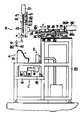
제 4 도는 코로나 방전 처리장치의 정면도.4 is a front view of the corona discharge treatment apparatus.
제 5 도는 상기 장치의 우측면도.5 is a right side view of the device.
제 6 도는 Y축 이동수단의 평면도.6 is a plan view of the Y-axis moving means.
제 7 도는 방전 전극과 고주파 인가수단과의 접속을 도시한 개략도.7 is a schematic diagram showing a connection between a discharge electrode and a high frequency application means.
* 도면의 주요부분에 대한 부호의 설명* Explanation of symbols for main parts of the drawings
1 : 설치 패널 패드 50 : 방전 전극1: mounting panel pad 50: discharge electrode
62 : 대향 전극 63 : 전극 기재62: counter electrode 63: electrode base material
64 : 도전층64: conductive layer
본 발명은 수지성형품의 코로나 방전처리에 사용되는 대향 전극에 관한 것이다.The present invention relates to a counter electrode used for corona discharge treatment of a resin molded article.
폴리프로필렌등의 폴리올레핀계 수지는 극성기가 적으므로 그 표면에 도료, 접착제, 인쇄제 등이 부착하기 어렵다는 특성이 있다.Since polyolefin resins, such as polypropylene, have few polar groups, it has the characteristic that a paint, an adhesive agent, a printing agent, etc. are hard to adhere to the surface.
여기서 상기 수지의 표면에 도료, 접착, 인쇄 등을 행하는 경우에는 그 전처리로서 표면에 개질처리를 행하고 상기 부착성을 향상시킬 필요가 있다.When coating, adhering, printing, etc. to the surface of the said resin here, it is necessary to perform a modification process to the surface as the pretreatment, and to improve the said adhesiveness.
이 폴리올레핀계 수지로 되어 있는 3차원 수지성형품의 개질처리로서, 종래에 있어서는 프레임처리(화염처리)나 중크롬산 용액등을 사용하는 산성용액 처리등이 행해져 왔지만, 최근에는 플라즈마 처리도 행해지게 되었다. 상기 플라즈마 처리는 수지성형품의 거의 전표면을 한번에 활성화할 수 있으므로 자동차용 범퍼, 몰 등의 도장, 접착 전처리에 큰 성과를 올리고 있다.As a modification treatment of a three-dimensional resin molded article made of this polyolefin resin, conventionally, an acid solution treatment using a flame treatment (flame treatment), a dichromic acid solution or the like has been performed, but in recent years, a plasma treatment has also been performed. Since the plasma treatment can activate almost the entire surface of the resin molded product at once, the plasma treatment has a great effect on the coating and adhesion pretreatment of bumpers and moles for automobiles.
그러나, 상기 플라즈마 처리에서는 감압된 플라즈마 가스 분위가 필요하므로 진공조, 진공펌프, 밸브 장치, 캐리어 가스 등이 많이 소요되어 고가의 설비를 요하는 데다가, 상기 진공조내를 감압하는데 시간이 걸린다는 문제가 있었다. 또 공정은 어떻게 하더라도 뱃치 처리를 취하지 않을 수 없으므로 공정의 자동화는 곤란하고 공정마다 진공이 끊어져 다음의 감압에 시간이 걸린다고 하는 문제도 있었다.However, the plasma treatment requires a reduced pressure of the plasma gas, which requires a lot of vacuum chambers, vacuum pumps, valve devices, carrier gases, etc., and requires expensive equipment, and it takes a long time to depressurize the vacuum chamber. . In addition, the batch process is inevitably required in any process, and automation of the process is difficult, and there is also a problem that the vacuum is cut for each process, and the next decompression takes time.
여기서, 본 발명자는 수지 필름의 개질 처리로서 행해지는 코로나 방전 처리에 착안하고 있지만, 이 처리방법을 3차원 수지 성형품의 개질 처리에 채용함에는 많은 곤란이 따른다. 그 하나는 성형품이 여러가지의 3차원 형상을 하고 있는 경우에는 이때가지의 롤형이나 평판형의 대량 전극으로는 상기 수지와의 사이에 큰 공기층이 생김은 물론 방전 전극과의 간극이 크게 되기 때문에 코로나 방전이 발생하지 않게 된다는 남점이다.Here, although this inventor pays attention to the corona discharge process performed as a reforming process of a resin film, when employ | adopting this processing method for the reforming process of a 3D resin molded article, many difficulty comes. One of them is that when a molded article has various three-dimensional shapes, a large air electrode having a roll-like or flat plate-like electrode has a large air layer between the resin and a large gap with the discharge electrode. This is a spot that will not occur.
따라서, 상기 대향 전극을 3차원 수지 성형품의 이면의 형상과 거의 동일 형상으로 형성하는 것을 생각할 수 있지만, 이 경우에는 상기 3차원 수지 성형품의 이면과 동일형상의 전극 기재를 형성하고, 이 표면에 박막형의 도전층을 피복시킴으로써 상기 대향 전극을 형성하고 있다.Therefore, although it is conceivable to form the counter electrode in a shape substantially the same as the shape of the back surface of the three-dimensional resin molded article, in this case, an electrode base material having the same shape as the back surface of the three-dimensional resin molded article is formed, and a thin film type is formed on this surface. The counter electrode is formed by covering the conductive layer.
그런데, 상기 방법으로 형성된 대향 전극상에 3차원 수지 성형품을 배치하는 경우에는 다음과 같은 문제점을 생각할 수 있다.By the way, when arrange | positioning a three-dimensional resin molded article on the counter electrode formed by the said method, the following problem can be considered.
즉, 상기 3차원 수지 성형품에 투공, 절결부등의 관통부분이 구비되어 있는 경우에는 그 부분으로 부터 상기 도전층이 방전 전극측에 노출하게 된다. 따라서, 상기 관통부분상에 코로나 방전중에 방전 전극이 위치하면 상기 코로나 방전이 흩어져 충분한 코로나 방전 처리가 행해지지 않는 것을 생각할 수 있다. 이 때문에 상기 대향 전극의 관통 부분과 대향하는 부분에 유전체로된 완충판을 설치하여야 하고 여분의 제조공정이 필요하다.That is, in the case where the three-dimensional resin molded article is provided with through portions such as perforations and cutouts, the conductive layer is exposed from the portions to the discharge electrode side. Therefore, it is conceivable that the corona discharge is scattered and sufficient corona discharge treatment is not performed when the discharge electrode is positioned on the penetrating portion during the corona discharge. For this reason, a buffer plate made of a dielectric material must be provided at the portion facing the through portion of the counter electrode, and an extra manufacturing process is required.
본 발명은 상기 문제점을 해결하기 위하여 코로나 방전 처리용 성형품의 피처리면의 이면에 배치되고 상기 성형품을 통해 방전 전극과 대향하는 대향 전극으로서, 상기 코로나 방전 처리용 성형품의 이면과 동일 또는 대략 동일 형상으로 형성된 전극 기재와, 그 내부에 형성된 도전층으로 구성되어 있는 수단을 채용하고 있다.The present invention is a counter electrode disposed on the back surface of the to-be-processed surface of the corona discharge-treated molded article and facing the discharge electrode through the molded article, in order to solve the above problems, having the same or substantially the same shape as the back surface of the molded product for the corona discharge treatment. The means which consists of the formed electrode base material and the conductive layer formed in the inside is employ | adopted.
본 발명의 대향 전극은 3차원 수지 성형품의 이면의 형상과 동일 또는 대략 동일하게 형성된 전극 기재와, 그 내부에 형성된 도전층으로 구성되어 있기 때문에 상기 3차원 수지 성형품에 투광이나 절결부의 관통부분이 구비되어 있는 경우에도 그 부분으로부터 상기 도전층이 방전 전극측에 노출하지 않는다. 따라서, 상기 투광이나 절결부의 상방에 방전 전극이 위치한 경우에도 상기 방전 전극으로부터의 코로나 방전이 흩어짐이 없이 균일한 코로나 방전을 발생시킬 수가 있고, 더우기 상기 절결부의 이면에 돌아서 들어간 부분까지 코로나 방전 처리가 행해진다.Since the counter electrode of the present invention is composed of an electrode substrate formed the same as or substantially the same as the shape of the back surface of the three-dimensional resin molded article, and a conductive layer formed therein, a penetration portion of the light-transmitting or cutout portion is formed in the three-dimensional resin molded article. Even when provided, the conductive layer is not exposed to the discharge electrode side from the portion. Therefore, even when the discharge electrode is located above the light projection or the cutout portion, it is possible to generate a uniform corona discharge without scattering the corona discharge from the discharge electrode. The process is performed.
이하, 본 발명을 구체화한 실시예를 도면에 따라 설명한다.EMBODIMENT OF THE INVENTION Hereinafter, the Example which actualized this invention is described according to drawing.
우선, 이 실시예에서 코로나 방전 처리되는 성형품에 관하여 간단히 설명하면 이 성형품은 3차원 수지 성형품으로서 3차원적인 凹凸을 가지는 것을 말한다. 또, 여기서 말하는 수지를 특히 유전체인 합성수지를 가르킨다.First, the molded article subjected to the corona discharge treatment in this embodiment will be briefly described as saying that the molded article has a three-dimensional shape as a three-dimensional resin molded article. In addition, the resin mentioned here points out the synthetic resin which is a dielectric material especially.
본 실시예에 따라 코로나 방전 처리하는 3차원 수지 성형품은 제 1 도 내지 제 3 도에 도시하는 바와같이 유전체인 PP수지로 형성된 자동차용 설치 패널 패드(1)ㄹ서, 그 표면에 PVC(폴리 염화 비닐) 수지제의 표피 시트가 접착됨으로써 설치 패널 패드가 구성되도록 되어 있다.According to the present embodiment, the three-dimensional resin molded article subjected to corona discharge treatment is an automobile installation panel pad (1) formed of PP resin, which is a dielectric material, as shown in FIGS. ) A skin panel sheet made of resin is adhered to each other so that an installation panel pad is formed.
상기 설치 패널 패드(1)는 그 상면(2)과 전면(3)과의 경계, 상면(2)과 측면(4)과의 경계등에 凸형의 코너부(5)를 가지고 있다.The mounting panel pad 1 has an
또, 설치 패널 패드 상면(2)의 좌우측에는 2개의 얕은 접시부(6, 7)가 설치되어 있다. 따라서, 제 2 도에 도시하는 바와같이 접시부(6, 7)의 저면 가장자리에서는 凹형의 코너부(9)가 각각 존재한다. 또, 상기 상면(2)의 좌단부에는 측면 디프로스터용 공기의 취출구(10)가, 똑같이 전면(3)의 좌우 양측에는 2개의 환개, 공기조절용 공기 취출구(11, 12)가 각각 형성되어 있다. 각 취출구(10, 11, 12)는 대략 4각 형상을 이루고, 가장자리 및 네 모퉁이에 R형의 코너부(13)가 형성되어 있다.Moreover, two
상기한 대로, 설치 패널 패드(1)는 3차원 수지 성형품임은 물론, 많은 코너부(5, 8, 9, 13)를 구비한 점에 특징을 가지는 것이다.As described above, the mounting panel pad 1 is a three-dimensional resin molded article, and is characterized by having
그리고, 다음에 상기 설치 패널 패드(1)를 코로나 방전 처리하기 위한 장치를 설명한다.Next, an apparatus for corona discharge treatment of the mounting panel pad 1 will be described.
이 코로나 방전 처리장치는 금속 프레임에 의해 전후 2단으로 형성된 베이스(80)상에 얹혀져 있고, 본 장치를 구분하면, A : 설치 패널 패드(1)를 고정함은 물론 그 이면에 대항 전극을 접촉시키기 위해 베이스(80)의 제 1 단째에 접지된 대향 전극 수단(A)과, B : 코로나 방전 처리와 이것을 3차원적으로 이동시키기 위한 이동 수단을 가지고, 베이스(80)의 제 2 단째에 배치된 방전 전극 수단(B)과, C : 상기 전극간에 고주파를 인가히기 위해 베이스(80)의 좌측의 선반(14)에 배치된 고주파인가 수단(C)과, D : 전극 이동 수단(B)을 제어하기 위해 베이스(80)의 우측에 접지된 제어 유니트(D)로 구성되어 있다. 이하, 상기 각부 A 내지 D의 상세를 차례로 설명한다.The corona discharge treatment apparatus is mounted on a
[대향 전극 수단(A)]Counter electrode means A
제 1 도, 2 도, 4 도 및 제 5 도에 도시하는 바와같이 베이스(80)의 제 1 단째에는 중공의 전극대(61)가 설치되어 있고, 상기 전극대(61)의 상부에는 설치 패널 패드(1)의 내부의 3차원 형상에 합치하도록 형성된 대향전극(62)이 설치되어 있고, 상기 설치 패널 패드91)를 내측으로부터 지지하도록 되어 있다.As shown in FIG. 1, FIG. 2, FIG. 4, and FIG. 5, the
이 대향 전극(62)은 상기 설치 패널 패드(1)의 이면의 3차원 형상가 동일 형상으로 형성된 에폭시 수지제의 전극 기재(63)와, 그 내부에 형성된 박막형의 도전층(64)으로 구성되어 있다.This counter electrode 62 is comprised from the
이 때문에 이 대향 전극(62)상에 상기 설치 패널 패드91)를 배치해도 그 취출구(10, 11, 12)로 부터 도전층(64)이 방전 전극(50)에 노출하지 않는다. 따라서, 코로나 방전중의 방전 전극(50)이 상기 취출구(10, 11, 12)상에 위치한 경우에도 상기 코로나 방전이 흩어지지 않고 더우기 상기 취출구(10, 11, 12)의 이면측까지 돌아 들어가 코로나 방전 처리가 행해지도록 되어 있다.For this reason, even if the said mounting panel pad 91 is arrange | positioned on this counter electrode 62, the conductive layer 64 is not exposed to the
또, 상기 대향 전극(62)은 설치 패널 패드(1)의 이면에 용융 에폭시 수지를 5㎜ 정도의 두께로 될때까지 충전하고, 그후 도전체로서의 은분말들은 도료(도 다이트)를 분무 도포하여 도전층(64)을 형성하고, 더우기 그 위에 상기와 똑같은 용융 에폭시 수지를 충전함으로써 형성된다.In addition, the counter electrode 62 is filled with a molten epoxy resin on the back surface of the installation panel pad 1 until it becomes about 5 mm thick. Then, silver powder as a conductor is spray-coated with a paint (painting die). It is formed by forming the conductive layer 64 and further filling the same molten epoxy resin as above.
전술한 대로, 본 실시예의 대향 전극(62)은 도전층(64)을 전극 기재(63)의 내부에 설치하였으므로 종래와 같이 상기 취출구(10, 11, 12)부분에서의 코로나 방전의 흩어짐을 방지하기 위해 대향 전극의 취출구(10, 11, 12)와 대향하는 부분에 유전체로된 완충판을 설치하고 상기 취출구(10, 11, 12)를 막는 처리를 행할 필요는 없고 따라서 상기 대향 전극(62)자체를 간단히 그리고 염가로 형성할 수 있고, 설비비의 저감, 재현성의 향상등에 효과적이다.As described above, the counter electrode 62 of the present embodiment is provided with a conductive layer 64 inside the
[방전 전극 수단(B)][Discharge electrode means (B)]
제 4 도 내지 제 6 도에 도시하는 바와같이, 방전 전극 수단(B)은 코로나 방전 전극(50)과, 이것을 X축(좌우)방향으로 이동시키기 위한 X축 이동 수단(20)과, 똑같이 Y축(전후)방향으로 이동시키기 위한 Y축이동 수단과, 똑같이 Z축(상하)방향으로 이동시키기 위한 Z축 이동 수단(40)으로 구성되어 있다.As shown in Figs. 4 to 6, the discharge electrode means B is the same as the
X축 이동 수단(20)에 있어서, 베이스(80)에는 수평 방향으로 연장하는 2개의 안내로드(28)가 설치되어 있다. 상기 안내 로드(28)에는 다음의 Y축 이동 수단(30)을 지지하기 위한 턴 테이블(26)이 X축 방향으로 미끄럼 가능하게 설치되어 있다. 즉, 턴 테이블(26)의 하면에는 지지부재(23)가 설치되고, 상기 지지부재(23)에 양 안내로드(28)가 삽입 관통됨으로써 턴 테이블(26)이 미끄럼 가능하게 되어 있다.In the X-axis moving means 20, the
더우기, 턴 테이블(26)의 하면중 지지부재(23)의 좌우측에는 나사결합부(23)가 부착되고, 상기 나사결합부(29)에는 1개의 스크류 축(27)이 나사식으로 결합되어 있다. 스크류 축(27)의 우단에는 치차(21a)가 설치되고, 상기 치차(21a)는 베이스(80)의 우단부에 설치된 서보 모터(25)의 치차(21b)와 맞물려 있다.In addition, the screw coupling portion 23 is attached to the left and right sides of the support member 23 in the lower surface of the turn table 26, and one screw shaft 27 is screwed to the screw coupling portion 29. . A gear 21a is provided at the right end of the screw shaft 27, and the gear 21a is engaged with the gear 21b of the
따라서, 서보 모터(25)가 회전하면 치차(21a, 21b)를 통해 스크류 축(27)이 회전하므로 상기 스크류 축(27)에 나사결합된 나사결합부(29)와 함께 턴 테이블(26)은 X축 방향으로 이동하도록 되어 있다.Accordingly, when the
다음에, Y축 이동 수단(30)에 있어서 턴 테이블(26) 상면의 양측부에는 각각 2개의 베어링(35)이 설치되어 있다. 좌우의 베어링(35)사이에는 2개의 스크류 축(31)이 회전가능하게 그리고 전진후퇴는 불가능하게 설치되고 양측(31)은 수평방향으로 평행하게 연장하고 있다. 각 스크류축(31)의 전후에는 치차(36a)가 설치되고, 각 치차(36a)는 베이스(80)의 후단부에 설치된 서보 모터(32)의 치차(36b)와 맞물린다.Next, two
2개의 스크류 축(31)에는 양축(31)에 걸쳐져 있는 나사결합부(34)가 나사결합되어 있고, 상기 나사 결합부재(34)의 중앙부에는 전방으로 연장하는 Y축 아암(33)이 설치되어 있다. Y축 아암(33)의 전단에는 다음의 Z축 이동수단(40)이 고정되어 있다.The two
따라서, Y축 이동 수단(30)에 있어서도 서보모터(32)의 회전이 치차(36), 스크류 축(31) 및 나사 결합부재(34)의 순으로 전달되고 Z축 이동수단(40)이 Y축 방향으로 이동하도록 되어 있다.Therefore, also in the Y-axis moving means 30, the rotation of the servomotor 32 is transmitted in the order of the gear 36, the
다음에, Z축 이동 수단(40)에 있어서, Y축 아암(33)의 전단에는 고정 테이블(41)이 수직으로 고정되어 있다. 고정 테이블(41)의 전단에는 2개의 안내로드(42)가 고정되고, 양 로드(42)는 상하방향으로 평행하게 연장하고 있다.Next, in the Z-axis moving means 40, the fixed table 41 is vertically fixed to the front end of the Y-axis arm 33. Two guide rods 42 are fixed to the front end of the fixed table 41, and both rods 42 extend in parallel in the vertical direction.
양 안내 로드(42)에는 이에 걸쳐져 있는 미끄럼 부재(44)가 미끄럼 가능하게 설치되고, 상기 미끄럼 부재(44)의 중앙부에는 암나사(도시되지 않음)가 형성되어 있다. 상기 암나사에는 상방으로 연장하는 스크류 축(46)이 나사결합되고, 상기 스크류 축(46)은 고정 테이블(41)의 상부에 설치된 설치된 서보 모터(45)의 회전축(47)에 직결되어 있다.Sliding
한편, 미끄럼 부재(44)의 중앙부에는 하방으로 연장하는 Z축 아암(43)이 그 상단부에서 고정되고, 상기 Z축 아암(43)의 하단부에는 코로나 방전용의 방전 전극(50)이 항상 거의 연직상태로 파지되고 있다. 따라서, 서보 모터(45)를 회전시키면 스크류축(46)이 회전하여 미끄럼 부재(44)를 통해 Z축 아암(44) 및 방전전극(50)이 승강하도록 되어 있다.On the other hand, the Z-axis arm 43 extending downward is fixed to the central portion of the sliding
대기중에 배치되는 상기 방전 전극(50)은 스테인레스강으로 형성된 직경 약 2㎜ 봉형의 피파지부(51)와, 똑같이 스테인레스강으로 되어 있고 상기 피파지부(51)의 선단에 부착된 직경 약 6㎜의 구형의 방전선단부(52)로 되어 있다. 피파지부(51)는 상술한 대로 Z축 아암(43)에 항상 거의 연직 상태로 파지되고, 상기 각 이동 수단(20, 30, 40)에 의해 이동되는 때도 경사져 운동하지 않도록 되어 있다.The
제 7 도에 도시하는 바와같이 상기 방전 전극(50)의 주위에는 스테인레스강 등으로 형성된 그물형의 보호통(53)을 설치하는 것이 바람직하다. 상기 보호통(53)에 의해 코로나 방전시에 있어서 고주파 노이즈의 복사를 방지할 수가 있기 때문이다.As shown in FIG. 7, it is preferable to provide a mesh-shaped
[고주파 인가수단(C)][High frequency application means (C)]
제 4 도, 7 도에 도시하는 바와같이 상기 대향 전극(62)과 방전 전극(50)에는 고주파 발진기(16)와 고압 트랜스(17)로 이루어진 고주파 인가수단(C)이 접속되어 있다. 또, 고주파 노이즈 대책을 위해 고주파 발진기(16)로부터도 직접 접지가 취해지고 있다.As shown in FIG. 4 and FIG. 7, the counter electrode 62 and the
고주파 발진기(16)에는 20 내지 30KHz, 최대 출력 350W의 고주파를 발생하는 단덱사의 제품(상품명 HV 05-2)가 사용되고 있다. 고압 트랜스(17)는 고주파 발진기(16)의 고주파 출력을 승압하여 전극(63, 50)간에 고전압을 인가하기 위한 것으로서, 똑같이 단덱사의 제품(상품명 슈퍼-C)이 사용되고 있다.The
[제어 유니트(D)][Control unit (D)]
제어 유니트(D)에는 컴퓨터 등을 사용한 제어회로(도시되지 않음)가 조립되고, 상기 제어회로에는 방전 전극(50)을 설치 패널 패드(1)의 표면 근방에 이동시키기 위해 X, Y, Z축 이동 수단(20, 30, 40)의 작동을 제어하는 운동 프로그램이나 고주파 인가수단(C)의 작동 개시와 정지를 제어하는 프로그램 등이 서입되고 있다.A control circuit (not shown) using a computer or the like is assembled in the control unit D, and the X, Y, and Z axes are provided in the control circuit to move the
이 제어 유니트(D)와 상기 고주파 인가수단 (C)은 베이스(80)를 사이에 두고 상당한 간격을 두고 배치되어 있고 전원은 따로따로 독립해서 취해져 있다. 고주파 인가 수단(C)으로부터 누설하는 고주파 노이즈에 의해 제어 유니트(D)의 컴퓨터가 오작동하는 것을 방지하기 위한 것이다. 또, 같은 이유로부터 상기 고주파 발진기(16), 고압 트랜스917) 및 방전 전극(50)을 접속하는 코드는 확실히 시일드할 필요가 있다.The control unit D and the high frequency applying means C are arranged at a considerable interval with the base 80 interposed therebetween, and the power supply is taken independently. It is for preventing the computer of the control unit D from malfunctioning by the high frequency noise leaking from the high frequency applying means (C). For the same reason, the cord connecting the
또, 제 5 도에 도시하는 바와같이, 베이스(80)중 상기 대향 전극 수단(A)으로부터 후방의 위치에는 코로나 방전 처리시에 발생하는 오존등의 가스를 배출하기 위한 배기수단(E)이 배치되고 있다.5, the exhaust means E for discharging gas, such as ozone which generate | occur | produces at the time of a corona discharge process, is arrange | positioned in the position of the base 80 back from the said counter electrode means A. It is becoming.
그런데, 이상과 같이 구성된 코로나 방전 처리 장치를 사용하여 설치 팬ㄹ 패드(1)를 발전 처리하는 방법에 관하여 설명한다.By the way, the method to generate power generation treatment of the installation fan pad 1 using the corona discharge treatment apparatus comprised as mentioned above is demonstrated.
우선, 형성된 설치 패널 패드(1)에 이형제나 손작업에 기인하는 오염물 등이 부착하고 있는 경우에는 이것을 트리클로로에탄 등의 유기용제로 세정하는 전처리를 행하는 것이 바람직하다. 확실히 코로나 방전 처리를 행하기 위한 것이다. 그러나, 이형제나 오염물이 없는 경우나 경미한 경우에는 전처리를 행할 필요는 없다.First, when contaminants or the like caused by a releasing agent or a hand work adhere to the formed installation panel pad 1, it is preferable to perform a pretreatment for washing this with an organic solvent such as trichloroethane. It is for surely performing a corona discharge process. However, the pretreatment does not need to be performed in the absence or milder release or milder condition.
다음에, 제 1 도, 2 도, 4 도, 5 도에 도시하는 바와같이, 대향 전극 수단(A)의 대향 전극(62)에 설치 패널 패드(1)를 끼운다. 이때 대향 전극(62)은 그 표면 내지 전체가 설치 패널 패드91)의 이면의 3차원 형상과 대략 동일 형상으로 형성되어 있기 때문에 상기 대향 전극(62)의 표면 전체가 설치 패널 패드(1)의 이면 전체에 확실히 접촉한다.Next, as shown in FIG. 1, FIG. 2, FIG. 4, and FIG. 5, the mounting panel pad 1 is fitted to the counter electrode 62 of the counter electrode means A. As shown in FIG. At this time, the entire surface of the counter electrode 62 is the back surface of the mounting panel pad 1 because the entire surface of the counter electrode 62 is formed in substantially the same shape as the three-dimensional shape of the back surface of the mounting panel pad 91. Make sure you touch the whole thing.
따라서, 유전체 PP수지로 형성된 설치 패널 패드(1)는 그 거의 전체가 대향 전극(62)에 대하여 전기적으로 유효하게 결합되고, 대향 전극(62)과 방전 전극(50)과의 간격을 항상 작게 하는 것도 가능하게 된다. 그 결과 방전 전극(50)으로부터 코로나 방전이 발생하기 쉽게 된다.Therefore, almost all of the mounting panel pads 1 formed of the dielectric PP resin are electrically coupled to the counter electrode 62, and the gap between the counter electrode 62 and the
지금 가령 대향 전극(62)의 표면과 설치 패널 패드(1)의 이면이 접촉되지 않고 그 사이에 공기층이 형성되면, 이 공기층은 절연층으로서 작용하여 코로나 방전이 발생하기 어렵게 된다. 본 실시예에서는 이 공기층을 확실히 없애 상기 전기적 결합을 실현하고 있는 것이다.If the surface of the counter electrode 62 and the back surface of the mounting panel pad 1 are not in contact with each other now, and an air layer is formed therebetween, the air layer acts as an insulating layer, making corona discharge less likely to occur. In this embodiment, this air layer is reliably removed to realize the electrical coupling.
다음에, 배기 수단(E)을 작동시켜 줌으로써 제어 유니트(D)의 스위치를 넣어 방전 전극 수단(B)에 있어서의 각 축의 이동 수단(20, 30, 40)을 코로나 방전 처리의 시작 위치로 설정한다. 이때, ① 방전 전극(50)의 피파지부(51)는 항상 연직상태로 지지되어 있고 ② 방전 선단부(52)는 설치 패널 패드 (1)의 앞 가장자리의 좌단으로부터 상방으로 약 10㎜의 간격을 두고 위치된다.Next, by operating the exhaust means E, the control unit D is switched to set the moving
다음에, 고주파 인가 수단(C)의 고주파 발진기(16)가 작동되면 그 고주파 출력은 고압 트랜스(17)에서 승압되고, 대향 전극(62)과 방전 전극(50)간에 25KV의 고주파가 인가된다. 이렇게 되면 방전 선단부(52)중 상면(2)에 대향하고 있는 부분과 그 상면(2)간의 대기중에 코로나 방전이 발생하고 상면(2)의 코로나 방전 처리가 개시된다.Next, when the
X, Y, Z축 이동 수단(20, 30, 40)은 제어 유니트(D)로부터의 제어신호에 기초하여 작동하는 서보 모터(25, 32, 45)의 회전에 의해 각각의 방향으로 이동하고, 방전 전극(50)은 설치 패널 패드(1)의 표면 근방을 이동해 간다.The X, Y, Z axis moving means 20, 30, 40 move in each direction by rotation of the
또, 상기 방전 전극(50)의 이동 속도는 상기 방전 조건하에서는 1 내지 250㎜/초의 범위내에서 임의로 설정할 수가 있지만, 본 실시예에서는 충분한 코로나 방전 효과와 처리 소요 시간의 단축을 아울러 고려해서 150㎜/초로 하였다.In addition, although the moving speed of the said
이상과 같은 왕복 이동을 동반하는 코로나 방전 처리에 의해 설치 패널 패드(1)의 표면 전체가 코로나 방전 처리되고, 접착제 등의 부착성이 향상한다. 본 실시예의 코로나 방전 처리에 의한 젖음성의 향상은 종래의 프레임 처리(화염처리)와 같은 정도이다.By the corona discharge treatment accompanying the above reciprocating movement, the whole surface of the installation panel pad 1 is corona discharge-processed, and adhesiveness, such as an adhesive agent, improves. The improvement of the wettability by the corona discharge treatment of this embodiment is about the same as the conventional frame treatment (flame treatment).
그리고, 제 2 도에 도시하는 바와같이, 방전 전극(50)이 취출구(10, 11, 12)나 접시부(6, 7)의 상방을 통과할 때에는 상기 방전 전극(50)은 그 낙차분만 하방으로 이동된다. 이때 상기 대향 전극(62)의 취출구(10, 11, 12)와 대향하는 부분은 도전층(64)이 노출하지 않기 때문에 코로나 방전이 흩어지지 않는다. 따라서, 상기 취출구(10, 11, 12)의 내측면 및 이면측, 접시부(6, 7)의 저면, 코너부(9, 13)등도 확실하고 균일한 코로나 방전 처리된다. 더우기, 상기 표피 시트의 접착시에 그 표피시트를 상기 치출구(10, 11, 12)의 이면측까지 감아넣어 접착해도 상기 이면까지 코로나 방전 처리가 행해지고 있기 때문에 확실히 양자를 접착시킬 수가 있다.As shown in FIG. 2, when the
상기 코로나 방전 처리의 현상은 방전에 의해 생기는 다량의 전자의 흐름이 합성 수지(본 실시예에서는 PP)에 충돌하고, 그 충돌 에너지가 탄소와 수소의 결합을 부분적으로 파괴하고, 합성 수지 표면을 산화, 이온화시켜 활성화시키기 위한 것이라 생각된다.In the phenomenon of the corona discharge treatment, a large amount of electrons generated by the discharge impinge on the synthetic resin (PP in this embodiment), and the collision energy partially destroys the bond between carbon and hydrogen, and oxidizes the surface of the synthetic resin. It is considered to be ionized and activated.
또, 상기 코로나 방전은 제 7 도에 도시하는 바와같은 방전 선단부(52)로부터 극히 균일한 방전 패턴을 가지고 넓어지므로 그때마다의 설치 패널 패드(1)의 원내는 충분하게 처리된다. 이것은 방전 선단부(52)가 구형(곡면 형상)이기 때문에 코로나 방전이 일점(뾰족한 부분이나 귀퉁이)등에 집중하지 않고 균일하게 분산하기 때문이다.In addition, since the corona discharge is widened from the
이와같이, 본 실시예의 코로나 방전 처리 장치에 의하면 종래의 플라즈마 처리에 있어서의 진공조, 진공펌프, 밸브기구, 캐리어 가스등의 대규모 설비나 감압에 요하는 준비시간 등이 불필요하게 되고, 방전 전극(50)등에 의해 대기중에서 코로나 방전 처리를 발생시켜 이것을 이동시킬 뿐으로 PP 수지제 설치 패널 패드(1)의 표면 개질을 행할 수 있다. 따라서, 설비비나 설비 공간을 대폭으로 절감할 수 있을 뿐만 아니라 처리시간도 단축할 수 있다.As described above, according to the corona discharge treatment apparatus of the present embodiment, large-scale facilities such as a vacuum chamber, a vacuum pump, a valve mechanism, a carrier gas, and a preparation time required for decompression are unnecessary in the conventional plasma processing, and the
더우기, 적어도 방전 선단부가 곡면 형상인 방전 전극(51)을 설치 패널 패드(1)의 표면을 따라 이동시키므로 코너부(5, 8, 9, 13)도 확실히 처리할 수가 있다.Furthermore, the
또, 본 발명은 상기 실시예에 한정되는 것은 아니고, 예를들어 다음에 도시하는 바와같이 변경하여 구체화하는 것도 가능하다.In addition, this invention is not limited to the said Example, For example, it can also be changed and actualized as shown below.
(1) 상기 대향 전극(62)의 도전층(64)은 상기 실시예의 도전성 도료외에, Au, Cu, Al, Zn등의 모든 금속을 사용하는 것이 가능하다.(1) As the conductive layer 64 of the counter electrode 62, all metals such as Au, Cu, Al, and Zn can be used, in addition to the conductive paint of the above embodiment.
(2) 상기 도전층(64)의 형성방법은 상기 실시예의 플라즈마 도포 외에, 솔칠, 진공 증착, 스퍼터링 등의 모든 형성 방법을 사용할 수 있다.(2) As the method for forming the conductive layer 64, any method of forming such as brushing, vacuum deposition, sputtering, etc. can be used in addition to the plasma coating in the above embodiment.
(3) 상기 방전 전극 수단(B0에 있어서의 X, Y, Z축 이동 수단(20, 30, 40)의 구조를 변경하거나, 이에 대신하여 다관절형의 로보트 등을 사용하거나 하는 것도 가능하다. 또 대향 전극 수단(B)에 3차원 이동기구를 설치하고, 설치 패널 패드(1)를 이동시켜 방전 전극(50)에 접근시키도록 해도 좋다.(3) It is also possible to change the structure of the X, Y, Z axis moving means 20, 30, 40 in the discharge electrode means B0, or to use a multi-joint robot or the like instead. In addition, a three-dimensional moving mechanism may be provided in the counter electrode means B, and the mounting panel pad 1 may be moved to approach the
(4) 본 발명은 상기 설치 패널 패드91)이외에도, 자동차용 범퍼, 자동차용 몰, 오토바이의 흙받이 외에, 더우기 각종 산업기구, 가정용품등의 성형후에 도장, 접착, 인쇄 등이 필요한 모든 3차원 수지 성형품의 대향 전극으로서 사용할 수 있음은 물론, 2차원 수지 성형품의 대향 전극으로서도 사용할 수 있다.(4) The present invention, in addition to the installation panel pad 91, in addition to the bumper for cars, the mall for cars, the fenders of motorcycles, in addition, all three-dimensional, such as painting, bonding, printing, etc. required after molding of various industrial equipment, household goods, etc. Not only can it be used as a counter electrode of a resin molded article, it can also be used as a counter electrode of a two-dimensional resin molded article.
이상 상술한 바와같이 본 발명의 코로나 방전처리용 대향 전극은 코로나 방전 처리용 성형품의 이면과 동일 또는 대략 동일하게 형성된 전극 기재와, 그 내부에 형성된 도전층으로 구성되어 있기 때문에 투공이나 절결부등의 관통부분을 구비한 성형품이라도 상기 관통 부분에서 코로나 방전이 흩어짐이 없이 어떤 부분에 있어서도 균일하게 코로나 방전 처리를 행할 수가 있다고 하는 우수한 효과를 나타낸다.As described above, the counter electrode for corona discharge treatment of the present invention is composed of an electrode substrate formed on the same or substantially the same as the back surface of the molded article for corona discharge treatment, and a conductive layer formed therein, such as perforations and cutouts. Even a molded article having a penetrating portion exhibits an excellent effect that the corona discharge treatment can be uniformly performed at any portion without scattering the corona discharge in the penetrating portion.
Claims (2)
Applications Claiming Priority (2)
| Application Number | Priority Date | Filing Date | Title |
|---|---|---|---|
| JP61101317A JPS62256839A (en) | 1986-04-30 | 1986-04-30 | Counter electrode for corona discharge treatment |
| JP101317 | 1986-04-30 |
Publications (2)
| Publication Number | Publication Date |
|---|---|
| KR870010659A KR870010659A (en) | 1987-11-30 |
| KR900002718B1 true KR900002718B1 (en) | 1990-04-23 |
Family
ID=14297434
Family Applications (1)
| Application Number | Title | Priority Date | Filing Date |
|---|---|---|---|
| KR1019870000534A KR900002718B1 (en) | 1986-04-30 | 1987-01-23 | Counter electrode frr corona discharge treatment |
Country Status (2)
| Country | Link |
|---|---|
| JP (1) | JPS62256839A (en) |
| KR (1) | KR900002718B1 (en) |
-
1986
- 1986-04-30 JP JP61101317A patent/JPS62256839A/en active Granted
-
1987
- 1987-01-23 KR KR1019870000534A patent/KR900002718B1/en not_active IP Right Cessation
Also Published As
| Publication number | Publication date |
|---|---|
| JPH0313255B2 (en) | 1991-02-22 |
| KR870010659A (en) | 1987-11-30 |
| JPS62256839A (en) | 1987-11-09 |
Similar Documents
| Publication | Publication Date | Title |
|---|---|---|
| US4836901A (en) | Corona discharge treating method and apparatus for resin moldings | |
| WO2006083758A1 (en) | Apparatus and method for plasma treating and dispensing an adhesive/sealant onto a part | |
| US6612910B1 (en) | Liquid crystal glass substrate, method of cutting the liquid crystal glass substrate, cutter for the liquid crystal glass substrate and display using the liquid crystal glass substrate | |
| KR900002718B1 (en) | Counter electrode frr corona discharge treatment | |
| CN210031337U (en) | Plastic-coated film coating device | |
| CN104955281A (en) | Method for manufacturing or repairing stereoscopic circuit on surface of three-dimensional high polymer material | |
| JP2000117750A (en) | Apparatus for cleaning mold for resin molding and method for cleaning it | |
| JPH0612682B2 (en) | Method of manufacturing counter electrode for corona discharge treatment | |
| KR900003047B1 (en) | Corona discharge discharge treatment of molded resin | |
| KR890004070B1 (en) | Method for treating surface of polyolefin molding | |
| JP2000294472A (en) | Stage with static eliminating function, method for static- eliminating processing body, and processing apparatus and seal agent coater using the same | |
| CN114919289A (en) | Ink-jet printing equipment and ink-jet printing method | |
| JPS62167043A (en) | Molded shape for corona discharge treatment | |
| JPS62179532A (en) | Molding for corona discharge treatment | |
| CN220516286U (en) | Surface cleaning and activating device | |
| JPH0312569B2 (en) | ||
| CN215325190U (en) | Feeding device for processing electronic components | |
| JPH0312571B2 (en) | ||
| JPS62112630A (en) | Counter electrode for corona discharge treatment and corona discharge treatment using same | |
| KR102187547B1 (en) | Precision Discharge Control Dispenser with Plasma Pre-treatment | |
| JPH0312572B2 (en) | ||
| CN219519327U (en) | Waterproof coating flush coater for screw | |
| CN216639311U (en) | Toughened hollow glass coating equipment suitable for different thicknesses | |
| JPS62106934A (en) | Electrode for corona discharge and corona discharge treatment using the same | |
| CN201619027U (en) | Solar panel film removing device |
Legal Events
| Date | Code | Title | Description |
|---|---|---|---|
| A201 | Request for examination | ||
| G160 | Decision to publish patent application | ||
| E701 | Decision to grant or registration of patent right | ||
| GRNT | Written decision to grant | ||
| FPAY | Annual fee payment |
Payment date: 19970415 Year of fee payment: 8 |
|
| LAPS | Lapse due to unpaid annual fee |