KR900002263B1 - Method for preparing optical-fiber preform - Google Patents
Method for preparing optical-fiber preform Download PDFInfo
- Publication number
- KR900002263B1 KR900002263B1 KR1019860002464A KR860002464A KR900002263B1 KR 900002263 B1 KR900002263 B1 KR 900002263B1 KR 1019860002464 A KR1019860002464 A KR 1019860002464A KR 860002464 A KR860002464 A KR 860002464A KR 900002263 B1 KR900002263 B1 KR 900002263B1
- Authority
- KR
- South Korea
- Prior art keywords
- gas
- core
- heating
- clad
- gap
- Prior art date
Links
Images


Classifications
-
- C—CHEMISTRY; METALLURGY
- C03—GLASS; MINERAL OR SLAG WOOL
- C03B—MANUFACTURE, SHAPING, OR SUPPLEMENTARY PROCESSES
- C03B37/00—Manufacture or treatment of flakes, fibres, or filaments from softened glass, minerals, or slags
- C03B37/01—Manufacture of glass fibres or filaments
- C03B37/02—Manufacture of glass fibres or filaments by drawing or extruding, e.g. direct drawing of molten glass from nozzles; Cooling fins therefor
- C03B37/025—Manufacture of glass fibres or filaments by drawing or extruding, e.g. direct drawing of molten glass from nozzles; Cooling fins therefor from reheated softened tubes, rods, fibres or filaments, e.g. drawing fibres from preforms
-
- C—CHEMISTRY; METALLURGY
- C03—GLASS; MINERAL OR SLAG WOOL
- C03B—MANUFACTURE, SHAPING, OR SUPPLEMENTARY PROCESSES
- C03B37/00—Manufacture or treatment of flakes, fibres, or filaments from softened glass, minerals, or slags
- C03B37/01—Manufacture of glass fibres or filaments
- C03B37/012—Manufacture of preforms for drawing fibres or filaments
- C03B37/01205—Manufacture of preforms for drawing fibres or filaments starting from tubes, rods, fibres or filaments
- C03B37/01211—Manufacture of preforms for drawing fibres or filaments starting from tubes, rods, fibres or filaments by inserting one or more rods or tubes into a tube
-
- C—CHEMISTRY; METALLURGY
- C03—GLASS; MINERAL OR SLAG WOOL
- C03B—MANUFACTURE, SHAPING, OR SUPPLEMENTARY PROCESSES
- C03B20/00—Processes specially adapted for the production of quartz or fused silica articles, not otherwise provided for
-
- G—PHYSICS
- G02—OPTICS
- G02B—OPTICAL ELEMENTS, SYSTEMS OR APPARATUS
- G02B6/00—Light guides; Structural details of arrangements comprising light guides and other optical elements, e.g. couplings
-
- G—PHYSICS
- G02—OPTICS
- G02B—OPTICAL ELEMENTS, SYSTEMS OR APPARATUS
- G02B6/00—Light guides; Structural details of arrangements comprising light guides and other optical elements, e.g. couplings
- G02B6/02—Optical fibres with cladding with or without a coating
-
- Y—GENERAL TAGGING OF NEW TECHNOLOGICAL DEVELOPMENTS; GENERAL TAGGING OF CROSS-SECTIONAL TECHNOLOGIES SPANNING OVER SEVERAL SECTIONS OF THE IPC; TECHNICAL SUBJECTS COVERED BY FORMER USPC CROSS-REFERENCE ART COLLECTIONS [XRACs] AND DIGESTS
- Y02—TECHNOLOGIES OR APPLICATIONS FOR MITIGATION OR ADAPTATION AGAINST CLIMATE CHANGE
- Y02P—CLIMATE CHANGE MITIGATION TECHNOLOGIES IN THE PRODUCTION OR PROCESSING OF GOODS
- Y02P40/00—Technologies relating to the processing of minerals
- Y02P40/50—Glass production, e.g. reusing waste heat during processing or shaping
- Y02P40/57—Improving the yield, e-g- reduction of reject rates
-
- Y—GENERAL TAGGING OF NEW TECHNOLOGICAL DEVELOPMENTS; GENERAL TAGGING OF CROSS-SECTIONAL TECHNOLOGIES SPANNING OVER SEVERAL SECTIONS OF THE IPC; TECHNICAL SUBJECTS COVERED BY FORMER USPC CROSS-REFERENCE ART COLLECTIONS [XRACs] AND DIGESTS
- Y10—TECHNICAL SUBJECTS COVERED BY FORMER USPC
- Y10S—TECHNICAL SUBJECTS COVERED BY FORMER USPC CROSS-REFERENCE ART COLLECTIONS [XRACs] AND DIGESTS
- Y10S65/00—Glass manufacturing
- Y10S65/15—Nonoxygen containing chalogenides
- Y10S65/16—Optical filament or fiber treatment with fluorine or incorporating fluorine in final product
-
- Y—GENERAL TAGGING OF NEW TECHNOLOGICAL DEVELOPMENTS; GENERAL TAGGING OF CROSS-SECTIONAL TECHNOLOGIES SPANNING OVER SEVERAL SECTIONS OF THE IPC; TECHNICAL SUBJECTS COVERED BY FORMER USPC CROSS-REFERENCE ART COLLECTIONS [XRACs] AND DIGESTS
- Y10—TECHNICAL SUBJECTS COVERED BY FORMER USPC
- Y10S—TECHNICAL SUBJECTS COVERED BY FORMER USPC CROSS-REFERENCE ART COLLECTIONS [XRACs] AND DIGESTS
- Y10S65/00—Glass manufacturing
- Y10S65/90—Drying, dehydration, minimizing oh groups
Landscapes
- Chemical & Material Sciences (AREA)
- Engineering & Computer Science (AREA)
- Physics & Mathematics (AREA)
- Organic Chemistry (AREA)
- Materials Engineering (AREA)
- Geochemistry & Mineralogy (AREA)
- Manufacturing & Machinery (AREA)
- Life Sciences & Earth Sciences (AREA)
- General Life Sciences & Earth Sciences (AREA)
- General Physics & Mathematics (AREA)
- Optics & Photonics (AREA)
- Manufacture, Treatment Of Glass Fibers (AREA)
- Glass Melting And Manufacturing (AREA)
Abstract
Description
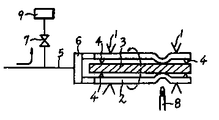
제 1 도(a) 및 (b)는 본 발명의 일실시 태양의 개략 설명도.1 (a) and (b) are schematic explanatory diagrams of an embodiment of the present invention.
* 도면의 주요부분에 대한 부호의 설명* Explanation of symbols for main parts of the drawings
(1) : 유리선반(旋盤) (2) : 클래드용관(1) Glass shelves (2) Clad tubes
(3) : 코어재 (4) : 지지재(3): core material (4): support material
(5) : 가스도입라인 (6) : 회전코넥터(5): Gas introduction line (6): Rotating connector
(7) : 밸브 (8) : 가열원(7): valve (8): heating source
(9) : 폐가스처리장치(9): waste gas treatment system
본 발명은 저손실의 광파이버용 모재의 제조방법에 관한 것이다. 광파이버용 모재의 제조방법에 있어서, 클래드재가 되는 관의 속에 이 클래드재보다도 고굴절률을 가진 코어용 유리롯드를 삽입하여 가열 중실화(中實化)해서, 광파이버용 모재를 제조하는 롯드인 튜우브법은 대표적인 제조방법의 하나로서 알려져 있으나, 이 방법에는 코어재와 클래드재의 계면에 기포·불순물등의 결함이 남기 쉬우며, 광파이버로 했을 때에 광의 손실이 커진다고 하는 결점이 있었다.The present invention relates to a method for producing a low loss optical fiber base material. In the manufacturing method of the base material for an optical fiber, the tubing method which is a rod which inserts the glass rod for cores which have a higher refractive index than this clad material in the inside of the tube used as a clad material, heat-solidifies, and manufactures the base material for optical fibers. Although is known as one of the typical manufacturing methods, defects such as bubbles and impurities are likely to remain at the interface between the core material and the clad material, and there is a drawback that the loss of light increases when the optical fiber is used.
이 결점을 해결하는 방법으로서, 일본국특공소 59-46898호 공보에 있어서, 할로겐화금속가스와 산소가스와의 혼합가스를 공급하여 이 혼합원료가스를 산화분해시켜서, 석영관내 표면과 코어바깥표면에 부착시키는 방법이 제안되어 있다.As a method for resolving this drawback, Japanese Patent Application Laid-Open No. 59-46898 discloses a mixed gas of a metal halide gas and an oxygen gas to oxidatively decompose the mixed raw material gas to the surface inside the quartz tube and the surface outside the core. A method of attaching is proposed.
또 일본국특개소 54-135810호 공보에는, 유리롯드와 유리관의 사이에, 불소와 붕소 혹은 그 어느 하나를 함유하는 유리형성원료를 산소가스와 함께 공급가열하여, 유리봉의 표면위와 유리관의 내벽에, 유리봉보다도 굴절률이 낮은 석영유리층을 형성하는 방법이 제안되어 있다.In Japanese Patent Laid-Open No. 54-135810, a glass-forming material containing fluorine and boron or either is heated together with oxygen gas between the glass rod and the glass tube, and heated on the surface of the glass rod and the inner wall of the glass tube. A method of forming a quartz glass layer having a lower refractive index than that of a glass rod has been proposed.
또한 일본국특공소 59-6261, 58-52935각호 공보에는 코어재와 클래드재의 용착 중실화전에, 관한 롯드와의 간극에, 산소가스의 공존하에서 고온도로 가열되었을 때에, 융착중실화되는데 필요한 온도보다 높은 비등점 또는 승화점을 가진 Si의 할로겐화물과 같은 물질을 함유하지 않은, 융착일체화할 때에 생성물이 거의 완전히 휘산되는, 유리표면변성 처리재를 사용하는 방법이 제안되어 있다.Also, Japanese Unexamined Patent Publications 59-6261 and 58-52935 disclose that the gap between the core material and the clad material prior to welding solidification is higher than the temperature required for fusion solidification when heated at high temperature in the presence of oxygen gas. A method of using a glass surface modification treatment which does not contain a material such as a halide of Si having a high boiling point or sublimation point, in which the product is almost completely volatilized upon fusion incorporation has been proposed.
그러나, 상기 각호공보에 기재된 방법에 따라, 광의파장 1.3~1.6㎛ 대 영역에서 사용되는 장거리 대용량 통신용의 저손실 싱글모우드파이버를 제작하였던바, OH 기에 의한 흡수손실과 코어·클래드의 계면결함에 의하는 것으로 생각되는 산란손실이 크고, 1.3㎛ 이상의 장파장대에 필요로 하는 0.5㏈/㎞ 이하의 저손실의 특성은 도저히 얻을 수 없다고 하는 결과를 얻었다.However, according to the method described in each of the above publications, a low loss single mode fiber for long-distance large capacity communication used in the wide wavelength range of 1.3 to 1.6 µm was fabricated, and due to the absorption loss due to the OH group and the interfacial defect between the core and the clad. The scattering loss is considered to be large, and the low loss characteristic of 0.5 mW / km or less required for a long wavelength band of 1.3 µm or more is hardly obtained.
본 발명자들이, 상기 각호 공보에 기재된 종래법을 상세히 검토하였던바, OH기의 오염원은 코어록드표면에 확산한 화학흡착하고 있는 OH기, 및 가열중실화시의 코어재와 클래드재의 간극의 분위기에 함유되는 수분으로서, 광파이버의 코어와 클래드의 경계이고 OH 기 함유층이 존재하는 것이 판명되었다.The present inventors have studied in detail the conventional method described in the above-mentioned publications. The source of the OH group is determined by the chemical adsorption of the OH group diffused on the surface of the core lock, and the atmosphere of the gap between the core material and the clad material at the time of heat deterioration. As the water contained, it was found that the core of the optical fiber and the cladding were present and that an OH group containing layer was present.
상술한 일본국특공소 59-6261, 58-52935 각호 공보에 기재된 공지기술에 따라, 중실화전에 예를들면 SF6, CCl2F2등의 불소를 함유하는 가스를 기상(氣相)처리재로서 가열처리하면, 이 기상처리재의 에칭작용에 의하여 코어용롯드표면과 클래드재의 내부표면에 화합흡착하고 있는 OH 기층을 제거할 수 있으나, 코어롯드가 열변형하지 않는 1900℃ 이하의 온도로 가열하면, 코어롯드와 클래드재의 내표면이 거칠게되어, 젖빛유리형상으로 불투명하게 된다. 이와같은 표면상태의 롯드를 중실화하면, 광파이버의 코어와 클래드의 경계에 구조결함이 남아서, 큰 산란손실이 생기는 결과가 된다. 또, 중실화전의 가열처리에, 기상처리제로서 불소를 함유하지 않은 예를들면 SOCl2, CCl4등의 가스를 사용하면, 에칭작용을 가지지 않기 때문에, 광파이버의 코어와 클래드의 경계에 고온도의 OH 기층이 남아서, OH 기에 의한 흡수손실이 생기는 결과가 된다.According to the known techniques described in Japanese Unexamined Patent Publication Nos. 59-6261 and 58-52935, the gaseous-treatment material is treated with fluorine-containing gas such as SF 6 and CCl 2 F 2 before solidification. When the heat treatment is carried out, the OH base layer which is chemically adsorbed on the surface of the core rod and the inner surface of the clad material can be removed by the etching action of the gas phase treatment material. However, when the core rod is heated to a temperature of 1900 ° C. or lower, which does not thermally deform, The inner surface of the core rod and the cladding material becomes rough and becomes opaque in frosted glass shape. When the rod of such a surface state is solidified, structural defects remain at the boundary between the core and the clad of the optical fiber, resulting in a large scattering loss. In addition, when a gas such as SOCl 2 , CCl 4, etc., which does not contain fluorine, is used for the heat treatment before the solidification, it does not have an etching effect. Therefore, the temperature of the core of the optical fiber and the cladding is high. The OH base layer remains, resulting in absorption loss due to the OH group.
또 상기한 일본국특공소 59-46898, 특개소 54-135810 각호 공보에 기재된 공지기술에 따라, 석영관내표면과 코어바깥 표면에 유리층을 퇴적시켜도, 역시 광파이버의 코어와 클래드의 경계에 고농도 OH 기층이 남아서, OH 기에 의한 큰 흡수손실이 생겼다. 또한, 가열표면처리 후의 중실화시의 코어재와 클래드재의 간극에 N2, O2, He 가스등만을 사용하면, 배관시스템의 누설등에 의하여, 가스의 로점(수분함유량)을 안정하게 낮게 유지하는 것은 곤란하며, 장파장대이고 저손실의 저 OH 기의 광파이버를, 재현성(再現性)좋게, 경제적으로 제조하는 것은 곤란하다.In addition, according to the well-known techniques described in Japanese Patent Application Laid-Open No. 59-46898 and Japanese Patent Laid-Open No. 54-135810, even when a glass layer is deposited on the inner surface of the quartz tube and the outer surface of the core, a high concentration of OH is formed at the boundary between the core and the clad of the optical fiber. The base layer remained, resulting in a large absorption loss due to the OH group. In addition, when only N 2 , O 2 , He gas, etc. are used in the gap between the core material and the clad material during the solidification after the heating surface treatment, it is possible to stably maintain the low dew point (water content) of the gas due to leakage of the piping system. It is difficult to produce an optical fiber of low OH group having a long wavelength and low loss with good reproducibility and economical.
본 발명의 목적은, 상기한 종래 공지기술의 결점을 극복하여, 장파장대이고 저손실의 광파이버를 경제적으로 제조할 수 있는 광파이버용 모재의 제조방법을 제공하는데 있다.SUMMARY OF THE INVENTION An object of the present invention is to provide a method of manufacturing a base material for an optical fiber that overcomes the above-mentioned drawbacks of the prior art and can economically produce an optical fiber with a long wavelength and low loss.
본 발명은 석영유리롯드를 코어재로 하고, 이 코어재보다 낮은 굴절률을 가진 클래드재의 속에 상기 코어재를 삽입하여 가열함으로서, 상기 코어재와 상기 클래드재와의 간극을 중실화하여 광파이버용 모재를 제조하는 방법에 있어서, 중실화하기 이전에 상기 간극에 적어도 규소의 할로겐화합물과 불소계가스와 산소가스를 함유하고, 또한 Si/F의 몰비(比)가 1/300〈Si/F〈1/5의 범위에 있는 혼합가스를 흐르게 하고, 관의 외부에 있는 가열원으로 가열한 후, 또 상기 간격의 분위기를 할로겐을 함유한 화합물과 산소가스의 혼합가스 분위기로 하여, 온도 1900℃ 이상으로 가열해서 중실화하는 것을 특징으로 하는 광파이버용 모재의 제조방법이다.According to the present invention, a quartz glass rod is used as a core material, and the core material is inserted into a clad material having a lower refractive index than the core material and heated to thereby solidify the gap between the core material and the clad material to provide a base material for an optical fiber. In the manufacturing method, at least the halogen compound of silicon, the fluorine gas, and the oxygen gas are contained in the said gap before solidification, and the molar ratio of Si / F is 1/300 <Si / F <1/5 After flowing a mixed gas in the range of, and heating with a heating source outside the tube, and the atmosphere of the interval is a mixed gas atmosphere of a compound containing halogen and oxygen gas, and heated to a temperature of 1900 ℃ or more It is a manufacturing method of the base material for optical fibers characterized by solidifying.
본 발명에서 사용하는, 규소의 할로겐화합물로서는, 예를들면 SiCl4, SiBr4, SiF4, Si2F6, Si2Cl6, SiFCl3, SiF2Cl2등을 들수 있으며, 또 불소계가스로서는 예를들면 CCL2F2, CF4, SF6, F2, SO2F2등을 들 수 있다.Examples of the halogen compound of silicon used in the present invention include SiCl 4 , SiBr 4 , SiF 4 , Si 2 F 6 , Si 2 Cl 6 , SiFCl 3 , SiF 2 Cl 2 , and the like. for example, a CCL 2 F 2, CF 4, SF 6, F 2, SO 2 F 2 or the like.
또 가열처리시에, 상기에 첨가하여 염소계가스, 예를들면 Cl2, SOCl2등을 탈수제로서 혼합하여도 좋다.In addition, during the heat treatment, chlorine-based gas such as Cl 2 , SOCl 2 , and the like may be added as the dehydrating agent.
본 발명의 방법에 있어서는, 중실화전에 코어재와 클래드재와의 간극에 규소의 할로겐화합물, 불소계가스 및 산소가스를 흐르게 하여 가열함으로서, 롯드표면에 부착되어 있는 수분, 이물, 먼지등을 휘발성 할로겐화물로서 제거할 수 있는 동시에, 코어롯드 표면을 에칭하여 OH 기를 제거할수 있다.In the method of the present invention, volatile halogens, such as moisture, foreign matter, dust, and the like adhering to the surface of the rod are heated by flowing silicon halogen compounds, fluorine-based gases, and oxygen gases through a gap between the core material and the clad material before solidification. It can be removed as a cargo, while at the same time etching the corerod surface to remove OH groups.
본 발명의 방법에서는, 종래법에서는 롯드표면에 생긴 에칭에 의한 표면거치름이, 규소와 할로겐의 화합물을 혼합함으로서 저감되고, 중실화 후에는, 코어와 클래드의 경계에, 산란(散亂)의 원인이 되는 구조결함이 잔존하지 않는다. 이 사실은 본 발명자들이 연구도중에 발견한 것이며, 그 상세한 것은 명백하지는 않으나, 불소계가스에 의하여 유리표면의 고 OH 기층이 제거되는 동시에, 규소와 산소로부터 생긴 유리미립자가 표면에 퇴적하여, 표면의 거치름의 깊이가 완화되어 있는 것으로 추정된다.In the method of the present invention, in the conventional method, surface roughness due to etching generated on the rod surface is reduced by mixing silicon and halogen compounds, and after solidification, scattering is formed at the boundary between the core and the clad. The causal structural defect does not remain. This fact was discovered by the inventors during the study, and the details are not clear, but the high OH base layer on the glass surface is removed by the fluorine-based gas, and glass fine particles formed from silicon and oxygen are deposited on the surface, and the surface is mounted. The depth of the ice is assumed to be relaxed.
여기서 생긴 표면의 거치름은, 중실화시에 생기는 유리의 점성유동(粘性流動)으로 평활화되는데 충분할 정도로 경미한 것으로 되어있다고 생각된다.The roughness of the surface produced here is considered to be slight enough to be smoothed by the viscous flow of the glass generated at the time of solidification.
규소와 할로겐의 화합물로서 SiCl4를, 불소계가스로서 SF6을 사용하여, 다른조건을 일정으로 하고, SiCl4/SF6의 혼합비율을 표 1에 표시하는 바와같이 바꾸어, 프로포옴을 제작하여, 다시 와이어드로우잉하여 파이버화해서, 로스(손실)의 파장특성을 구하였다. 얻어진 파장특성의 그래프로부터 1/λ4에 비례하는 레이리 산란항(散亂項) 및 OH 기에 의한 흡수증(吸收增)을 공제하여 구한 산란로스와, λ=1.38㎛에서의 OH 흡수로스를 표 1에 합해서 표시한다. 또한 종래법인 SF6만을 흐르게 한 경우를 표 1의 No.6에 표시하였다.SiCl 4 is used as the compound of silicon and halogen, SF 6 is used as the fluorine-based gas, and other conditions are fixed, and the mixing ratio of SiCl 4 / SF 6 is changed as shown in Table 1 to produce a profile. The wire was drawn again and fiberized to determine the wavelength characteristics of loss (loss). From the graph of the wavelength characteristics obtained, the scattering loss obtained by subtracting the Rayleigh scattering term proportional to 1 / λ 4 and the absorption by the OH group, and the OH absorption loss at λ = 1.38 μm. Displayed in conjunction with Table 1. Moreover, the case where only SF 6 which is a conventional method is made to flow is shown in No. 6 of Table 1.
[표 1]TABLE 1

표 1의 결과에서, Si/F의 혼합몰비에는 최적치가 존재하며, 1/300〈Si/F〈1/5인 것이 명백하다. Si/F의 혼합몰비가 1/5을 초과하면 유리퇴적이 주가 되어, 유리표층의 에칭이 불충분하게 되기 때문에 OH 흡수로스가 증가되고있다. 또 Si/F가 1/300보다 작으면, 에칭에 의한 표면의 거치름이 깊게 되어, 중실화 후에도 산란원(散亂源)으로서 남는다. 따라서 1/300〈Si/F〈1/5가 되도록 혼합가스비율을 조제해간다.In the results of Table 1, there is an optimum value in the mixing molar ratio of Si / F, and it is clear that 1/300 < Si / F < 1/5. When the mixing molar ratio of Si / F exceeds 1/5, the glass deposition is mainly used, and the etching of the glass surface layer becomes insufficient, so that the OH absorption loss is increased. When Si / F is smaller than 1/300, the roughness of the surface by etching becomes deep and remains as a scattering source even after solidification. Therefore, the mixed gas ratio is prepared so that 1/300 < Si / F < 1/5.
또 중실화에 선행되는 전천리가열은 온도 500~1900℃의 범위에서 행하는 것이 바람직하며, 특히 바람직한 것은 1000~1600℃의 온도범위를 들 수 있다.Moreover, it is preferable to perform all-thermal heating which precedes solidification in the range of the temperature of 500-1900 degreeC, Especially preferably, the temperature range of 1000-1600 degreeC is mentioned.
상술한 바와같이, 중실화전의 가열처리를 한 후 롯드와 클래드재의 간극에 할로겐을 함유한 화합물과 산소가스의 혼합가스를 충전하여, 온도 1900℃ 이상으로 가열해서 중실화한다. 산소가스는 코어와 클래드경계의 분자레벨의 결함을 감소시키는 효과가 있으며, 산소이외의 예를들면 He 등의 불활성가스분위기에서는 자외부의 흡수가 크게 되고, 그테일의 영향에 의하여 근적외역(近赤外域)까지 로스가 증가해 버린다.As described above, after the heat treatment prior to the solidification, a mixture gas of a halogen-containing compound and oxygen gas is filled in the gap between the rod and the clad material, and heated to a temperature of 1900 占 폚 or more to solidify. Oxygen gas has the effect of reducing the defects in the molecular level of the core and cladding boundary. In the inert gas atmosphere other than oxygen, for example, the absorption of ultraviolet rays is increased, and the near-infrared region is affected by the tail effect. Loss will increase to 赤 外 域).
따라서 장거리, 대용량의 통신매체로서 사용되는 저손실광파이버의 제조에 있어서는, 중실화시에 코어와 클래드 간격의 분위기를 산소가스 분위기로 하는 것이 필요하다.Therefore, in the production of low-loss optical fibers used as long-distance, large-capacity communication media, it is necessary to make the atmosphere of the core and the clad gap an oxygen gas atmosphere at the time of solidification.
그러나 산소가스 단독으로는 수분이 함유되므로, 저 OH 기의 광파이버를 제조할 수 없기 때문에, 산소가스에 탈수제로서 할로겐을 함유하는 화합물을 혼합하는 것이 바람직하다. 할로겐을 함유하는 화합물로서는 예를들면 Cl2, F2, SOCl2, CCl4, SiF4, NF3, CCl2F2, CF4, SF6등을 들 수 있다.However, since oxygen gas alone contains moisture, it is not possible to produce an optical fiber of low OH groups, and therefore, it is preferable to mix a compound containing halogen as oxygen dehydrating agent in oxygen gas. Examples of the compound containing a halogen include Cl 2 , F 2 , SOCl 2 , CCl 4 , SiF 4 , NF 3 , CCl 2 F 2 , CF 4 , SF 6 , and the like.
다만 광의 파장 1㎛ 이상에서는 현저한 흡수를 나타내는 B2O3, P2O3와 같은 물질을 발생시킬 가능성을 가진 BBr3, BCl3, BF3, PCl3, POCl3, PF3와 같은 화합물을 사용하는 것은 바람직하지 않다.However the compounds, such as BBr 3, BCl 3, BF 3 ,
또한 중실화시의 가열온도는, 1900℃ 이상으로 유지하는 것이 바람직하며, 1900℃ 이하로는 산란로스가 증가하여 저손실파이버를 제조할 수 없다.In addition, it is preferable to maintain the heating temperature at the time of solidification above 1900 degreeC, and scattering loss increases to below 1900 degreeC, and low loss fiber cannot be manufactured.
이하에 본 발명의 방법을 구체적으로 설명한다.The method of the present invention is specifically described below.
제 1 도(a) 및 (b)는 본 발명의 일실시 태양을 설명하는 도면으로서, 도면중(1)은 유리선반, (2)는 클래드용관, (3)은 코어재, (4)는 지지재, (5)는 가스도입라인, (6)은 회전코넥터, (7)은 밸브, (8)은 가열원, (9)는 폐가스처리장치를 나타낸다. 클래드용관(2)의 내부에 코어재(코어용유리롯드)(3)를 삽입한 후, 이 관(2) 내에 가스도입라인(5)으로부터 규소의 할로겐화합물, 불소계가스 및 산소로 이루어진 혼합가스를 흐르게 하여, 가열원(8)을 사용하여 온도 500~1900℃의 범위로, 특히 바람직하게는 1000~1600℃의 온도범위에서 가열한다. 이때 클래드용관(2)은 20~80rpm으로 회전시키고, 가열원(8)은 50~250㎜/분으로 이동시키는 것이 바람직하다. 또 복수회(예를들면 2~10회)의 이동가열처리를 행하는 것이 바람직하다.1 (a) and (b) illustrate one embodiment of the present invention, in which (1) is a glass shelf, (2) is a cladding tube, (3) is a core material, and (4) is The support material (5) is a gas introduction line, (6) a rotary connector, (7) a valve, (8) a heating source, and (9) a waste gas treatment device. After inserting the core material (glass rod for core) 3 into the
이상과 같은 가열전 처리 후, 클래드용관(2)과 코어재(3)의 간극의 분위기를 할로겐을 함유한 화합물과 산소와의 혼합가스로 절환하고, 이어서 관(2)의 한쪽의 단부를 제 1 도(b)에 표시한 바와같이, 가열원(8)으로 가열 용착한다. 이때 밸브(7)를 용착직전에 개방상태로 하여, 클래드용관(2)내의 압력이 상승하지 않도록 한다. 이와같이 클래드용관(2)과 코어재(3)의 간극에 할로겐을 함유한 화합물과 산소와의 혼합가스를 충전한 상태에서, 회전하는 관(2)에 따라, 가열원(8)을 이동시킴으로서, 이 간극을 중실화해간다. 중실화시에 폐가스처리장치(9)에 의하여 감압하고, 관(2)의 내부의 압력을 부압(負壓)으로 하는 것도 가능하나, 감압할 때에 가열온도가 1900℃ 이하에서 중실화하지 않는 압력범위로 설정하는 것이 필요하다.After the pre-heating treatment as described above, the atmosphere of the gap between the
이상에 의하여, 코어용롯드와 클래드용관을 중실화하여 얻어진 프로포옴은, 그대로 광파이버용 모재로서 와이어드로우잉부에 이송되어도 좋으나, 경우에 따라서는, 클래드/코어직경비의 조정을 위하여, 다시 석영관 혹은 도우프된 클래드재로 피복하고, 혹은 외부법(外付法)에 의하여 피복층을 형성한 후에, 와이어드로우잉부에 이송되어 광파이버로 된다.As mentioned above, the profile obtained by solidifying the core rod and the cladding tube may be transferred directly to the wire drawing portion as a base material for the optical fiber, but in some cases, the quartz tube is again used for adjustment of the clad / core diameter ratio. Alternatively, the coated layer is coated with a doped clad material, or a coating layer is formed by an external method, and then transferred to a wire drawing unit to form an optical fiber.
[실시예 1]Example 1
화염가수분해법에 의하여 제작된 순실리카스우트를, 불소계가스를 함유한 분위기로 소결하여, 불소가 첨가된 석영유리롯드를 제작하였다. 이 롯드의 중심에 개공(開孔)가공을 실시하여, 클래드용 무수관(無水管)을 제작하였다. 이관은 외경 25㎜ψ, 길이 40mml, 석영유리와의 굴절률차 -Δ=0.32%였다.Pure silica scout prepared by flame hydrolysis was sintered in an atmosphere containing fluorine-based gas to prepare a quartz glass rod containing fluorine. Opening was performed in the center of this rod, and the waterless pipe for clad was produced. The transfer pipe had an outer diameter of 25 mm, a length of 40 mml, and a refractive index difference of -Δ = 0.32% from quartz glass.
상기 클래드용관에 SF6300CC/분, SOCl2, 70CC/분을 흐르게 하여, 50㎜/분의 이동속도로 이동하는 산수소바아너로 온도 2070℃로 4회 가열하여, 이관의 내표면을 평활화한 후에, 이관내에 코어용롯드로서 외경 3.4㎜ψ의 순석영 유리롯드를 삽입하였다. 이 순석영유리롯드는 기상축부법(氣相軸付法)으로 제작되어 저항로를 사용하여 3.4㎜ψ으로 연신되고, 삽입전에 초음파세정기를 사용하여, HF·알코올 및 순수종에서 세정된 것이다.SF 6 300CC / min, SOCl 2 , 70CC / min were flowed into the clad tube and heated four times at 2070 ° C. with an oxyhydrogen barner moving at a moving speed of 50 mm / min to smooth the inner surface of the pipe. Subsequently, a pure quartz glass rod having an outer diameter of 3.4 mm φ was inserted into the tube as a core rod. This pure quartz glass rod was manufactured by vapor phase axial method, stretched to 3.4 mm, using a resistance furnace, and washed with HF alcohol and pure species using an ultrasonic cleaner before insertion.
다음에 클래드용관에 도입하는 가스를, SiCl4, 120CC/분, SF6200CC/분, SOCl2, 70CC/분, O2800CC/분으로 절환하여 클래드재와 코어재의 간극에 흐르게한 후, 1300㎜/분으로 이동하는 산수소바아너로 온도 1460℃로 5회 가열전 처리하였다.Next, the gas introduced into the cladding tube was switched to SiCl 4 , 120CC / min, SF 6 200CC / min, SOCl 2 , 70CC / min, O 2 800CC / min and flowed into the gap between the cladding material and the core material, and then 1300. It was treated five times before heating at a temperature of 1460 ° C. with an oxyhydrogen barner moving at mm / min.
그후, 관내에 도입하는 가스중에 SiCl4만의 공급을 정지하여, SF6200CC/분, SOCl270CC/분, O2800CC/분의 혼합가스로 하고, 클래드용관의 한쪽의 단부를 산수소바아너로 밀착봉지하여, 코어용롯드와 클래드용관의 SF6과 SOCl2와의 O2로 이루어진 분위기로 충전한후, 3㎜/분의 이동속도의 산수소바아너로 온도 2140℃로 가열하여 중실화하였다.After that, the supply of only SiCl 4 was stopped in the gas introduced into the tube, and a mixed gas of SF 6 200CC / min, SOCl 2 70CC / min and O 2 800CC / min was used. in close contact with a bag, and then filled with a core for the rod and the SF 6 and O 2 atmosphere consisting of SOCl 2 with the clad yonggwan were screen by a solid dispersion water noodles Honor of 3㎜ / minute moving speed of the heating up to 2140 ℃.
이상에 의하여 얻어진 롯드는, 다시 외부법에 의하여 재킷이 되는 유리층을 피복하여, 외경/코어직경비가 125/8가 되도록 조정한 후, 와이어드로우잉하여 파이버화 하였다.The rod obtained by the above was again coated with the glass layer used as a jacket by the external method, it adjusted so that outer diameter / core diameter ratio might be 125/8, and wired by fiberization.
얻어진 파이버의 전송손실은, 파장 1.3㎛에서 0.34㏈/㎞, 파장 1.55㎛에서 0.17㏈/㎞이라는 저손실의 값이 달성되었다. 또 OH 기의 흡수손실도 파장 1.38㎛에서 1.2㏈/㎞이라는 낮은 것이였다.As for the transmission loss of the obtained fiber, a low loss value of 0.34 dB / km at a wavelength of 1.3 µm and 0.17 dB / km at a wavelength of 1.55 µm was achieved. The absorption loss of the OH group was also as low as 1.2 mA / km at a wavelength of 1.38 µm.
[비교예 1]Comparative Example 1
비교를 위하여, 중실화전의 가열처리에 흐르게 하는 혼합가스로부터, SiCl4를 제거한 이외는 실시예 1과 동일한 조건으로 프로포옴을 제작하여, 얻어진 파이버의 손실을 평가하였는바, 파장 1.3㎛에서 1.2㏈/㎞이라는 높은 손실로서, 장거리 통신용에 제공할 수 있는 싱글모우드파이버를 제작할 수 없었다.For comparison, from the mixed gas flowing in the heat treatment before solidification, a profile was produced under the same conditions as in Example 1 except that SiCl 4 was removed, and the loss of the obtained fiber was evaluated. With a high loss of / km, it was impossible to produce a single mode fiber that could be provided for long distance communication.
[비교예 2]Comparative Example 2
실시예 1의 프로세스에 있어서, 중실화전의 가열전처리를 생략하고, 또 코어와 클래드재의 간극에 SiCl4, 120CC/분, SF6200CC/분, SOCl270CC/분, O2800CC/분의 혼합가스를 흐르게 하여, 클래드관의 한쪽의 단부를 밀착봉지하여 상기 가스로 충전한 후 중실화한 프로포옴을 제작하였다. 얻어진 파이버의 손실특성은 OH 기의 흡수가 파장 1.38㎛에서 85㏈/㎞, 산란로스가 4.3㏈/㎞로 높았고, 저손실의 싱글모우드파이버를 제작할 수 없었다.In the process of Example 1, heating pretreatment before solidification is omitted, and a mixture of SiCl 4 , 120CC / min, SF 6 200CC / min, SOCl 2 70CC / min, and O 2 800CC / min is inserted into the gap between the core and the clad material. The gas was allowed to flow, and one end of the clad tube was tightly sealed and filled with the gas to prepare a solid profile. The loss characteristics of the obtained fiber were 85 ㏈ / km and scattering loss was 4.3 ㏈ / km at the wavelength of 1.38 占 퐉, and low loss single mode fiber could not be produced.
이상의 설명 및 실시예의 결과에서 명백한 바와같이, 본 발명의 방법은, 장거리 대용량통신용에 제공할 수 있는 저손실의 싱글모우드파이버를, 롯드인튜우브법에 있어서 제조가능하게 하는 것에 대하여, 제조코스트도 저감할 수 있는 산업상 유리한 방법이다.As apparent from the results of the above description and the examples, the method of the present invention reduces the manufacturing cost while allowing the low loss single mode fiber which can be provided for long-distance large-capacity communication to be manufactured in the rod-in-tubing method. It is an industrially advantageous way.
Claims (1)
Applications Claiming Priority (2)
| Application Number | Priority Date | Filing Date | Title |
|---|---|---|---|
| JP60-69203 | 1985-04-03 | ||
| JP60069203A JPS61227938A (en) | 1985-04-03 | 1985-04-03 | Preparation of parent material for optical fiber |
Publications (2)
| Publication Number | Publication Date |
|---|---|
| KR860008093A KR860008093A (en) | 1986-11-12 |
| KR900002263B1 true KR900002263B1 (en) | 1990-04-07 |
Family
ID=13395933
Family Applications (1)
| Application Number | Title | Priority Date | Filing Date |
|---|---|---|---|
| KR1019860002464A KR900002263B1 (en) | 1985-04-03 | 1986-04-01 | Method for preparing optical-fiber preform |
Country Status (6)
| Country | Link |
|---|---|
| US (1) | US4793842A (en) |
| EP (1) | EP0196671B1 (en) |
| JP (1) | JPS61227938A (en) |
| KR (1) | KR900002263B1 (en) |
| AU (1) | AU577938B2 (en) |
| DE (1) | DE3660424D1 (en) |
Families Citing this family (26)
| Publication number | Priority date | Publication date | Assignee | Title |
|---|---|---|---|---|
| JPS6236035A (en) * | 1985-04-18 | 1987-02-17 | Sumitomo Electric Ind Ltd | Production of optical fiber base material |
| DE3731806A1 (en) * | 1987-09-22 | 1989-06-08 | Rheydt Kabelwerk Ag | Process for the production of a preform for optical fibres |
| US5026409A (en) * | 1989-01-03 | 1991-06-25 | Hughes Aircraft Company | Preparation of fluoride glass optical preforms and fibers |
| ATE116448T1 (en) * | 1989-06-09 | 1995-01-15 | Heraeus Quarzglas | OPTICAL PARTS AND BLANKS MADE OF SYNTHETIC SILICON DIOXIDE GLASS AND METHOD FOR THEIR PRODUCTION. |
| DE4005730A1 (en) * | 1990-02-23 | 1991-08-29 | Kabelmetal Electro Gmbh | DEVICE FOR MANUFACTURING A LIGHTWAVE LEAD PREFORM |
| JPH04270132A (en) * | 1991-02-25 | 1992-09-25 | Sumitomo Electric Ind Ltd | Production of glass matrix for optical fiber |
| CA2125508C (en) * | 1993-06-16 | 2004-06-08 | Shinji Ishikawa | Process for producing glass preform for optical fiber |
| KR0177088B1 (en) * | 1993-11-29 | 1999-05-15 | 김광호 | The overcladding process for the first preform of single mode optical fiber and facilities thereof |
| GB2291643B (en) * | 1994-07-21 | 1998-01-28 | Pirelli General Plc | Optical fibre preforms |
| US5560759A (en) * | 1994-11-14 | 1996-10-01 | Lucent Technologies Inc. | Core insertion method for making optical fiber preforms and optical fibers fabricated therefrom |
| EP0716047A3 (en) * | 1994-12-02 | 1996-10-09 | Fibercore Inc | Method and apparatus for producing optical fiber preform |
| DE69630426T2 (en) * | 1995-08-31 | 2004-08-19 | Sumitomo Electric Industries, Ltd. | Dispersion-compensating fiber and process for its manufacture |
| KR0184481B1 (en) * | 1996-06-10 | 1999-05-15 | 김광호 | Highly productive optical fiber extraction facility and extraction process thereof |
| AU719475B2 (en) * | 1997-03-27 | 2000-05-11 | Samsung Electronics Co., Ltd. | Apparatus and method for overcladding optical fiber preform rod and optical fiber drawing method |
| EP1061055A4 (en) * | 1998-02-03 | 2006-11-15 | Sumitomo Electric Industries | Method of manufacturing optical fiber base material |
| JP3859189B2 (en) * | 1998-11-09 | 2006-12-20 | 信越石英株式会社 | Manufacturing method of optical fiber preform |
| US6767579B1 (en) * | 1998-11-24 | 2004-07-27 | Corning Incorporated | Methods for protecting silica-containing article in optical fiber manufacturing |
| US6210487B1 (en) * | 1999-08-26 | 2001-04-03 | Lucent Technologies Inc. | Disposable seal system with integral buffer |
| JP4759816B2 (en) * | 2001-02-21 | 2011-08-31 | 住友電気工業株式会社 | Optical fiber manufacturing method |
| US6574994B2 (en) | 2001-06-18 | 2003-06-10 | Corning Incorporated | Method of manufacturing multi-segmented optical fiber and preform |
| CA2454896A1 (en) * | 2003-01-16 | 2004-07-16 | Sumitomo Electric Industries, Ltd. | Method of producing optical fiber preform, and optical fiber preform and optical fiber produced with the method |
| KR20050071797A (en) * | 2004-01-02 | 2005-07-08 | 삼성전자주식회사 | Fabrication method for optical fiber preform |
| CN103011578B (en) * | 2012-12-17 | 2014-12-24 | 中天科技精密材料有限公司 | Device and method for manufacturing depressed cladding super-low water peak fiber mandril |
| US9212082B2 (en) | 2012-12-26 | 2015-12-15 | Heraeus Quarzglas Gmbh & Co. Kg | System and method for fabricating optical fiber preform and optical fiber |
| US20140186645A1 (en) * | 2013-01-02 | 2014-07-03 | Ofs Fitel, Llc | Manufacture of bend insensitive multimode optical fiber |
| US10185084B2 (en) * | 2016-02-23 | 2019-01-22 | Corning Incorporated | Layered glass structures |
Family Cites Families (7)
| Publication number | Priority date | Publication date | Assignee | Title |
|---|---|---|---|---|
| JPS54135810A (en) | 1978-04-14 | 1979-10-22 | Nippon Telegraph & Telephone | Manufacture of optical fiber parent material |
| JPS5852935B2 (en) * | 1978-11-20 | 1983-11-26 | 三菱マテリアル株式会社 | Manufacturing method for optical transmission materials |
| JPS5924092B2 (en) * | 1978-12-29 | 1984-06-07 | 三菱マテリアル株式会社 | Manufacturing method of optical fiber base material |
| JPS603019B2 (en) * | 1979-12-06 | 1985-01-25 | 三菱電線工業株式会社 | Manufacturing method of optical fiber base material |
| DE3031160A1 (en) * | 1980-08-18 | 1982-04-01 | Siemens AG, 1000 Berlin und 8000 München | Cleaning of glass surfaces by etching with gas - esp. where mixt. of oxygen and sulphur hexa:fluoride is used to clean bore of quartz tube used to make blank for mfg. optical fibres |
| NL8300650A (en) * | 1983-02-22 | 1984-09-17 | Philips Nv | METHOD FOR MANUFACTURING A SOLID FORM FOR DRAWING OPTICAL FIBERS |
| JPS6011244A (en) * | 1983-06-29 | 1985-01-21 | Hitachi Cable Ltd | Manufacture of optical fiber |
-
1985
- 1985-04-03 JP JP60069203A patent/JPS61227938A/en active Granted
-
1986
- 1986-04-01 KR KR1019860002464A patent/KR900002263B1/en not_active IP Right Cessation
- 1986-04-03 EP EP86104530A patent/EP0196671B1/en not_active Expired
- 1986-04-03 AU AU55605/86A patent/AU577938B2/en not_active Ceased
- 1986-04-03 DE DE8686104530T patent/DE3660424D1/en not_active Expired
-
1987
- 1987-12-21 US US07/139,141 patent/US4793842A/en not_active Expired - Lifetime
Also Published As
| Publication number | Publication date |
|---|---|
| JPH0510288B2 (en) | 1993-02-09 |
| EP0196671B1 (en) | 1988-07-27 |
| EP0196671A1 (en) | 1986-10-08 |
| AU5560586A (en) | 1986-10-09 |
| US4793842A (en) | 1988-12-27 |
| KR860008093A (en) | 1986-11-12 |
| DE3660424D1 (en) | 1988-09-01 |
| JPS61227938A (en) | 1986-10-11 |
| AU577938B2 (en) | 1988-10-06 |
Similar Documents
| Publication | Publication Date | Title |
|---|---|---|
| KR900002263B1 (en) | Method for preparing optical-fiber preform | |
| US4668263A (en) | Method for producing glass preform for optical fiber | |
| CA1120727A (en) | Method of producing glass optical filaments | |
| US6422042B1 (en) | Rit method of making optical fiber having depressed index core region | |
| US4772302A (en) | Optical waveguide manufacture | |
| EP0915064B1 (en) | Method of making segmented core optical waveguide preforms | |
| Schultz | Fabrication of optical waveguides by the outside vapor deposition process | |
| KR20050031110A (en) | Low loss optical fiber and method for making same | |
| US5090980A (en) | Method of producing glass bodies with simultaneous doping and sintering | |
| CA1260684A (en) | Optical waveguide manufacture | |
| JP2007513862A (en) | Alkali-doped optical fiber, preform thereof and method for producing the same | |
| US6776012B2 (en) | Method of making an optical fiber using preform dehydration in an environment of chlorine-containing gas, fluorine-containing gases and carbon monoxide | |
| US5163987A (en) | Method for producing glass preform for optical fiber | |
| EP1270522B1 (en) | Method for fabricating optical fiber from preforms, using control of the partial pressure of oxygen during preform dehydration | |
| JPH051221B2 (en) | ||
| JPH062599B2 (en) | Method for manufacturing base material for optical fiber | |
| JPS6259545A (en) | Production of optical fiber preform | |
| JPS61219733A (en) | Production of base material for optical fiber | |
| CA1261127A (en) | Optical waveguide manufacture | |
| RU2173672C2 (en) | Method of manufacture pieces with composite core for optical waveguides (versions) | |
| JPH0559850B2 (en) | ||
| JPS63256545A (en) | Production of base material for optical fiber | |
| JPS6120491B2 (en) |
Legal Events
| Date | Code | Title | Description |
|---|---|---|---|
| A201 | Request for examination | ||
| G160 | Decision to publish patent application | ||
| E701 | Decision to grant or registration of patent right | ||
| GRNT | Written decision to grant | ||
| FPAY | Annual fee payment |
Payment date: 20030320 Year of fee payment: 14 |
|
| LAPS | Lapse due to unpaid annual fee |