KR890003280B1 - Method of forming box-section frame members - Google Patents
Method of forming box-section frame members Download PDFInfo
- Publication number
- KR890003280B1 KR890003280B1 KR1019860002018A KR860002018A KR890003280B1 KR 890003280 B1 KR890003280 B1 KR 890003280B1 KR 1019860002018 A KR1019860002018 A KR 1019860002018A KR 860002018 A KR860002018 A KR 860002018A KR 890003280 B1 KR890003280 B1 KR 890003280B1
- Authority
- KR
- South Korea
- Prior art keywords
- blank
- cross
- mold
- section
- deformed
- Prior art date
Links
Images


Classifications
-
- B—PERFORMING OPERATIONS; TRANSPORTING
- B21—MECHANICAL METAL-WORKING WITHOUT ESSENTIALLY REMOVING MATERIAL; PUNCHING METAL
- B21D—WORKING OR PROCESSING OF SHEET METAL OR METAL TUBES, RODS OR PROFILES WITHOUT ESSENTIALLY REMOVING MATERIAL; PUNCHING METAL
- B21D51/00—Making hollow objects
-
- B—PERFORMING OPERATIONS; TRANSPORTING
- B21—MECHANICAL METAL-WORKING WITHOUT ESSENTIALLY REMOVING MATERIAL; PUNCHING METAL
- B21D—WORKING OR PROCESSING OF SHEET METAL OR METAL TUBES, RODS OR PROFILES WITHOUT ESSENTIALLY REMOVING MATERIAL; PUNCHING METAL
- B21D26/00—Shaping without cutting otherwise than using rigid devices or tools or yieldable or resilient pads, i.e. applying fluid pressure or magnetic forces
- B21D26/02—Shaping without cutting otherwise than using rigid devices or tools or yieldable or resilient pads, i.e. applying fluid pressure or magnetic forces by applying fluid pressure
- B21D26/033—Deforming tubular bodies
-
- B—PERFORMING OPERATIONS; TRANSPORTING
- B62—LAND VEHICLES FOR TRAVELLING OTHERWISE THAN ON RAILS
- B62D—MOTOR VEHICLES; TRAILERS
- B62D25/00—Superstructure or monocoque structure sub-units; Parts or details thereof not otherwise provided for
-
- Y—GENERAL TAGGING OF NEW TECHNOLOGICAL DEVELOPMENTS; GENERAL TAGGING OF CROSS-SECTIONAL TECHNOLOGIES SPANNING OVER SEVERAL SECTIONS OF THE IPC; TECHNICAL SUBJECTS COVERED BY FORMER USPC CROSS-REFERENCE ART COLLECTIONS [XRACs] AND DIGESTS
- Y10—TECHNICAL SUBJECTS COVERED BY FORMER USPC
- Y10T—TECHNICAL SUBJECTS COVERED BY FORMER US CLASSIFICATION
- Y10T29/00—Metal working
- Y10T29/49—Method of mechanical manufacture
- Y10T29/49805—Shaping by direct application of fluent pressure
Landscapes
- Engineering & Computer Science (AREA)
- Mechanical Engineering (AREA)
- Fluid Mechanics (AREA)
- Transportation (AREA)
- Combustion & Propulsion (AREA)
- Physics & Mathematics (AREA)
- Chemical & Material Sciences (AREA)
- Shaping Metal By Deep-Drawing, Or The Like (AREA)
- Recrystallisation Techniques (AREA)
- Superconductors And Manufacturing Methods Therefor (AREA)
- Crystals, And After-Treatments Of Crystals (AREA)
- Closing Of Containers (AREA)
- Audible-Bandwidth Dynamoelectric Transducers Other Than Pickups (AREA)
- Bridges Or Land Bridges (AREA)
- Making Paper Articles (AREA)
Abstract
Description
제1도 내지 제4도는 성형방법상 순차적 단계에 있는 튜브형 블랭크(Blank)의 사시도.1 to 4 are perspective views of tubular blanks in sequential steps in the molding process.
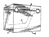
제5도 및 제6도는 본 제조 방법에 사용할 성형용 금형의 개략적 사시도.5 and 6 are schematic perspective views of a molding die for use in the present production method.
본 발명은 박스형 프레임부재들의 성형방법에 관한 것이다.The present invention relates to a method of forming box-shaped frame members.
예를 들면 자동차나 기타 도로용 차량의 제종에 있어서, 속이 비인(중공)박스형 단면의 프레임부재들을 자주 필요로 한다. 이러한 프레임부재들은 보통 한쌍 또는 그 이상의 평평하고 상호 대향하는 측면을 일반적으로 보유하고 있다. 단면의 속이 비어있다는 사실은 중량을 가볍게하는 한편, 훌륭한 경직성과 기타 바람직한 기계적 특성을 제공한다. 평평한 표면을 가지고 있다는 사실은 타 구조물에 연결하기가 쉬운것, 즉 예를들면, 용접이나 다른 고정수단이나, 또는 스터브(stub), 러그(lug), 브라켓 및 플렌지등의 연결수단에 의해 타 구조물과 결합시키는데 편리하다.For example, in the class of automobiles or other road vehicles, frame members of hollow box-shaped cross sections are frequently required. Such frame members usually have one or more flat, mutually opposite sides generally. The fact that the cross section is hollow makes the weight light while providing good rigidity and other desirable mechanical properties. The fact that it has a flat surface is easy to connect to other structures, ie welding or other fastening means, or other structures by means of connecting means such as stubs, lugs, brackets and flanges. It is convenient to combine with.
종래에는 이러한 구조물을 만들때, 시트 메탈(sheet metal)로 부터 채널모형의 반쪽 외곽을 스템핑(stamping)하여 내므로써 만들었다. 이 과정은 비교적 시간 소비적이고, 비용이 많이드는데 그 이유는 상기반쪽외곽을 스템핑해 내는데는 복잡한 프로그래시브금형의 사용이 필요하며, 또 적어도 용접작업을 자동적으로 수행하려면 복잡한 용접설비를 필요로하기 때문이다. 또한 스템핑 작업에는 많은 양의 시트메탈 손실이 초래된다. 용접할 부위가 넓기 때문에 제품이 불완전성이 띄는 경향이 있으며, 그 이유는 용접제어를 수행함에 근본적인 어려움이 내재하기 때문이다. 보통, 용접한 부위는 약간의 연마를 가해야 되는데, 이것도 시간 및 에너지 소비를 필요로 한다.Conventionally, when making such a structure, it was made by stamping out the outer half of the channel model from sheet metal. This process is relatively time consuming and costly because the stamping of the upper half requires the use of complex progressive molds, and at least complex welding equipment to perform the welding operation automatically. Because. Stamping operations also result in large sheet metal losses. Due to the large area to be welded, the product tends to be incomplete, because the fundamental difficulty in performing welding control is inherent. Normally, the welded area requires some polishing, which also requires time and energy consumption.
본 발명은 튜브형 블랭크가 금형의 동공내에 갇혀있는 동안 액체로 내부적 압력을 가하므로써 튜브형 블랭크를 둘레방향으로 팽창시켜 박스형 크레임부재를 성형시키는 방법을 제공하고자는 것이다. 이 방법은 종래의 스템핑한 부품을 다시 용접하는 방법보다 훨씬더 단순하며, 장비에 있어서도 덜 복잡한것을 필요로 한다.It is an object of the present invention to provide a method of forming a box-shaped frame member by expanding the tubular blank in the circumferential direction by applying internal pressure with liquid while the tubular blank is trapped in the cavity of the mold. This method is much simpler than the conventional method of rewelding stamped parts and requires less complexity in the equipment.
튜브형 블랭크를 팽창시키는 과정이 일려져 있기는하나, 본 출원인이 아는 종전의 제안은 강도 특성이나, 규격상의 균일성이나 반복가능성 박스형 프레임부재의 구조물로써 필요한 정확도를 가진 제품을 생산하지 못하였다.Although the process of inflating tubular blanks has taken place, previous proposals known to the applicant have not produced products with the required accuracy as strength properties, normative uniformity or repeatability box-shaped frame members.
본 방법에 있어서는 스무스하게 연속성을 띈 아치형모양 가급적 원형의 튜브블랭크의 측벽을 안쪽으로 변형시켜, 균일한 단면의 길죽한 변형체를 만들며, 이 변형은 최소한 구조물상의 원하는 양측 평면이 있어야할 위치에 해당하는 부위에 발생시키며, 이 변형은 곡면의 측벽부가 오히려 안으로 굽어들게 만든다. 이 작업은 블랭크가 원주방향으로 심한 팽창을 수반하지 않고 일반적으로 원하는 바의 평평한 표면의 단면을 가진 구조 물로 팽창 되게끔한다. 또한 상기 측벽의 내향변형은 블랭크의 일반적인 단면의 외형 또는 외피를 감소시키기 때문에, 블랭크를 금형속에 넣고 금형을 닫을때 금형의 부위가 블랭크를 찝어 상하게하는 일이없어 단면성형용금형속에 블랭크를 넣는것이 가능하다. 블랭크에 측벽을 내향 변형시키고, 금형동공의 다면 형태를 선택함에 있어서, 스무스하고 연속성을 띈 단면모형을 보존 시키도록 주의해야 한다. 이렇게하여 제품상의 기계적 약점이 될수 있는 단면 모형상의 날카로운 불연속성을 피하게된다. 확장단계에 있어서, 튜브의 모든 외부표면이 금형의 동공에 들어맞게끔 튜브형 블랭크를 팽창시키며 이렇게하여 높은 정확도와 균일성을 갖춘 금형동공의 내부표면규격이 복사되어 나온다.In this method, the side wall of a smoothly arcuately arcuate tube blank is deformed inwardly to create an elongated deformable body of uniform cross section, which is at least the position corresponding to the desired bilateral plane of the structure. This deformation causes the curved sidewall portion to bend inward. This operation causes the blank to expand into a structure with a generally flat surface cross section as desired without enormous swelling in the circumferential direction. In addition, since the inward deformation of the side wall reduces the appearance or skin of the general cross-section of the blank, it is not necessary to put the blank into the mold and close the mold so that the blank of the mold does not spoil the blank and put the blank into the cross-section mold. It is possible. Care should be taken to preserve the smooth, continuous cross-section of the sidewalls in the blank and to select the multifaceted shape of the mold cavity. This avoids sharp discontinuities on the cross-sectional model, which can be a mechanical weakness on the product. In the expansion step, the tubular blank is expanded so that all the outer surface of the tube fits into the cavity of the mold, thereby replicating the inner surface specification of the mold cavity with high accuracy and uniformity.
따라서 본 발명은 박스형 단면의 프레임부재를 형성하는 방법을 제공하는데 그 프레임부재의 최소한 길죽한 일부분은 균일한 단면으로 구성되고 최소한 두개의 일반적으로 대립한 평면의 표면을 구비하며, 이 제조방법의 구성은 다음과 같다. 즉, 연속성의 스무스한 아치형 단면의 튜브 블랭크를 주선하고, 이 블랭크의 긴 쪽 부위의 대립되는 부위를 내향 굴곡시켜 그 측벽을 변형시키는데 즉 최종제품에서 평면을 갖기를 원하는 그 해당부위에 변형을 가하여 이에 의해 연속성의 스무스한 아치형 단면을 가진 블랭크는 안으로 굽은 측벽 즉 대립되는 양쪽 내향 침강부를 가지며, 변형된 블랭크모양과 거의 같은 긴 동공을 가진 협력성 두쪼각의 금형내에 변형된 튜브 블랭크를 넣으며, 이 금형은 연속성의 스무스한 단면모양을 구비하여, 모든 횡반향의 규격이 변형된 블랭크보다 크며, 블랭크의 내향 침강 측벽에 대해 최소한 대체적으로 인접하고 평행한 모양을 갖도록 종방향 모양을 구비하고 있으며, 액체로서 내부 압력을 가하여 원주면방향으로 블랭크를 확장시켜 블랭크의 외부표면 전체가 금형의 내표면에 맞게끔 만들며, 금형 단면을 분리시키고, 완전히 확장된 블랭크를 금형으로 부터 분리해낸다.The present invention therefore provides a method of forming a frame member of a box-shaped cross-section, wherein at least the elongated portion of the frame member consists of a uniform cross section and has at least two generally opposing planar surfaces, the construction of which is As follows. In other words, arrange a continuous, smooth arc-shaped tube blank and bend the opposing parts of the long side of the blank inwardly to deform its sidewalls, i.e. by modifying the corresponding part where it is desired to have a plane in the final product. The blank with the continuous smooth arcuate cross section thereby has an inwardly curved sidewall, ie opposing inwardly settled sides, which encloses the modified tube blank in a mold of cooperative double-sided mold with a long pupil approximately equal to the modified blank shape. The mold has a continuous smooth cross-sectional shape, with all transverse dimensions larger than the modified blank, with a longitudinal shape such that it has at least a generally adjacent and parallel shape with respect to the inwardly settled sidewalls of the blank. To expand the blank in the circumferential direction by applying an internal pressure. To match the mold's inner surface, separate the mold section, and separate the fully expanded blank from the mold.
본 방법은 훌륭한 강도 특성과, 훌륭한 규격상의 정확도 및 균일성을 구비한 구조물을 생산할 수 있다.The method can produce structures with good strength properties and good standard accuracy and uniformity.
본 방법은 다른 잇점은 본 발명에 의한 한 성형방법을 다만 한 실시예로 도시하는 첨부도면을 참조해가며 아래에서 기술할 것이다.Another advantage of the method will be described below with reference to the accompanying drawings which show, by way of example, one molding method according to the invention.
도면을 참조하면, 제1도는 튜브형 금속블랭크(10)를 도시하며, 이것은 본 발명의 제조방법의 시작물질로 사용된다. 제4도는 제품 즉 프레임부재(11)를 도시하며 이것은 그렇게 성형하기를 원했든 것이다. 어느정도는 제품(11)의 윤곽 및 평평한 측면의 위치는 구조물의 의도된 최종 용도에의해 지시된 것이다. 그러나 본 발명의 목적을 위해서 바람직한 것은 제품(11)의 모양을 선택할때 그 횡단면 윤곽의 모든 곳에 거의같은 윤곽선을 갖도록 하여 블랭크(10)의 벽 어느점이나 너무 얇게 되거나 약하게 되지않도록하여, 최종 완제품내에 어떤 기계적 강도의 결함을 초래하는것을 피함이 좋다. 단면 주변상의 즉 구조물 제품의 벽두께의 약간의 비 균일성은 그 구조물의 용도에 따라 용납될수 있는 경우도 있다. 그러나 바람직하게는 완제품 구조물의 단면 윤곽의 가장큰 둘레부위가 가장 작은 둘레부위에 비하여 20%이상차이가 있어서는 아니되며 더 바람직하게는 5%이상 차이가 있어서는 아니된다.Referring to the drawings, FIG. 1 shows a tubular metal blank 10, which is used as a starting material for the manufacturing method of the present invention. 4 shows the product, ie the frame member 11, which would have been desired to be so shaped. To some extent the contours of the product 11 and the position of the flat sides are indicated by the intended end use of the structure. However, for the purposes of the present invention, it is preferred that the selection of the shape of the product 11 have approximately the same contour everywhere in the cross-sectional contour so that any point of the wall of the blank 10 is not too thin or too weak, in the final finished product. It is good to avoid causing defects of any mechanical strength. Some non-uniformity on the periphery of the cross section, ie the wall thickness of the structural product, may be acceptable depending on the application of the structure. However, preferably the largest perimeter of the cross-sectional contour of the finished structure should not differ by more than 20% compared to the smallest perimeter and more preferably not more than 5%.
또한 바람직하게는 완제품 프레임부재(11)의 단면 둘레는 블랭크(10)의 단면둘레에 비해여 5% 이상 커서는 아니된다. 출원인이 발견한 것은 적어도 구입하게 쉬운 등급의 강철튜브로서 블랭크의 단면 둘레가 5%이상 확대되며 블랭크의 벽이 극심하게 약화되거나, 금이가거나, 우그러지는 경향이있다.Also preferably, the circumference of the end face of the finished frame member 11 is not greater than 5% compared to the circumference of the end face of the blank 10. Applicant's finding is a steel tube of at least an easy-to-purchase grade, which extends more than 5% around the cross section of the blank and tends to be extremely weak, cracked or warped.
튜브금속을 완전 소둔한 경우에는 튜브단면의 주변을 20%까지 확장할 수 있으나, 그러나 블랭크 재료에 대해 소둔과 같은 특별한 사전처리를 하지않고 확장을 수행하는 것이 선호된다. 선호된 형태에 있어서, 튜브벽의 약한 지점이나 금이가는 일을 초래하지 않고, 원하는 단면 윤곽을 블랭크에 부여하기 위하여 완제품 프레임부재(11)는 그 모든 단면부위에 있어서, 균일한 단면 윤곽을 구비하며 블랭크(10)의 단면 둘레에 비하여 약2내지 4%크게한다.Full annealing of the tube metal can extend the periphery of the tube section by 20%, but it is preferred to perform the expansion without special pretreatment such as annealing on the blank material. In the preferred form, the finished frame member 11 has a uniform cross-sectional contour at all of its cross-sections in order to give the blank the desired cross-sectional contour without causing weak spots or cracking of the tube walls. It is about 2 to 4% larger than the circumference of the blank 10.
도면에서 볼수있는 바와같이 본 실시예는 자체의 보조 프레임인데, 그 바람직한 제품형태는 횡방향 중앙면에 대하여 대칭적이며, 직선형 중간부분(12)을 구비하며, 이 부위의 양 끝은 굴곡전환부 즉 엘보(13)를 통하여 한 끝 부분(14)에 연결되며, 이 끝 부분(14)은 중간부분(12)에 대하여 비스듬한 각으로 기울어져 있다. 각 끝부분(14)은 중간부분(12)의 중심축으로부터 바깥쪽으로 서로 같은 각도로, 예를들면 약 135°각으로 뻗어있으며 이렇게하여 부분(12및14)들은 제1평면에서 형성된다. 각 끝부분(14)은 또 다른 굴곡전환부 즉 엘보(16)를 거쳐 외측 끝부분(17)에 연결된다. 각 외측 끝부분(17)은 같은 평면상에서 부분들(12및14)에 의해 형성된 평면에 대해 일정각으로 뻗어있다. 각 외측 끝부분(17)은 일반적으로 보조프레임의 횡방향 중심면에 평행하게 뻗어있거나 또는 그에 대하여 약간 바깥쪽으로 각을 이루어 뻗어 있을 것이다.As can be seen in the drawing, this embodiment has its own auxiliary frame, the preferred form of which is symmetrical with respect to the transverse center plane and has a straight middle portion 12, both ends of which are bent transitions. That is, it is connected to one end portion 14 through the elbow 13, and this end portion 14 is inclined at an oblique angle with respect to the middle portion 12. Each end 14 extends at the same angle to the outside from the central axis of the middle part 12, for example at an angle of about 135 ° such that the parts 12 and 14 are formed in the first plane. Each end 14 is connected to the outer end 17 via another bend switch, ie elbow 16. Each outer end 17 extends at an angle to the plane formed by the parts 12 and 14 on the same plane. Each outer end 17 will generally extend parallel to the transverse center plane of the auxiliary frame or at an angle outwardly relative thereto.
제4도에 도시한 바와같이 원하는 바의 보조프레임을 비원형 단면윤곽을 가지고있다. 본 출원인이 발견한 것은 제품의 구조적 허약성을 피하기 위해서는 모든 횡단면부위에 있어서 윤곽이 스무스하게 연속성을 띄며 날카로운 각이나 불연속성을 가져서는 아니되며 이러것을 있을시는 스트레스의 집적을 일으키고 구조적 허약성을 유발하게 된다. 이리하여 예를들면 제4도에 도시한 보조 프레임에서, 프레임의 중간부분(12)은 일반적으로 사다리꼴의 단면윤곽(18)을 구비하여 경사진 측면(19및21)을 동반하며, 대체적인 평행측면(22및 23)을 구비한다. 각 측면들이 결합하는 부위는 완만하게 둥근 모서리 부분으로 구성되며, 각 측면(19내지23)자체도 완만하게 볼록한 곡면을 나타낼수도 있다. 각 끝부분(14)은 대체적인 정사각형단면(24)으로서 상부 및 하부변(26및27)과 횡변(28및29)을 구비한다. 외측 끝부분(17)들은 각각 일반적으로 사각형 윤곽(31)으로서 상부 및 하부변(32및33)과 횡변(34및36)을 구비한다. 단면 윤곽(18)에서와 같이, 단면윤곽(24및31)은 전체적으로 스무스한 연속성을 가지며, 둥근 모서리 부분으로서, 대체적인 직성형의 변(26내지 29및 32 내지 36)을 접합시키고 있다. 이변 자체들도 완만하게 외향으로 볼록한 굴곡면을 이루어도 좋다. 일반적으로 사다리꼴 단면의 중간부분(12)과 각 끝부분(14)사이에 있는 전환부분(13)은 부분들(12및14)의 끝과 각각 스무스하게 융합하며, 이 전환부의 중간부위는 대체적으로 원형이다.As shown in Fig. 4, the auxiliary frame as desired has a non-circular cross section. Applicants have found that in order to avoid structural fragility of the product, the contours are smoothly continual in all cross-sectional areas and should not have sharp angles or discontinuities, which will cause stress accumulation and structural weakness. Thus, for example in the auxiliary frame shown in FIG. 4, the middle portion 12 of the frame is generally provided with a trapezoidal cross-sectional contour 18, with inclined sides 19 and 21, and generally parallel. With
각 끝부분(14)과 각 외측 끝부분(17)사이의 전환부분(16)은 일반적으로 직사각형 단면이다. 여기서도 역시, 부분들(14 및 17)의 각 끝과 스무스하게 융합한다. 이렇게 상하변(26 및 27)이 외측 끝부분 단면의 상하변(32 및 33)으로 연장되어 갈때 그 중간 전환부분(16)은 그 단면의 높이에 있어 태이퍼져 가는 경향이 있고, 한편 전환부분(16)의 측변들은 끝부분(14)으로부터 외측끝부분(17)으로 향함에 따라 바깥쪽으로 벌어진다.The transition 16 between each end 14 and each outer end 17 is generally rectangular in cross section. Here too, smooth fusion with each end of portions 14 and 17. As the upper and lower sides 26 and 27 extend to the upper and lower sides 32 and 33 of the outer end section, the intermediate transition portion 16 tends to taper at the height of the cross section, while the transition portion ( The sides of 16 open outwardly from the end 14 toward the outer end 17.
상기 보조 프레임부재를 성형시키는 방법에 있어서 블랭크(10)는 원하는 제품 프레임부재의 대체적인 윤곽으로 굴곡시켜서 중간부분(12a)과, 외향 굴곡 끝부분(14a)과, 외측 끝부분(17a)을 형성시킨다. 도시한 바와 같이 블랭크(10)의 굴곡시는 그 전체 길이에 걸쳐 제2도에서 도시한 바와 같이, 원형의 단면(18a)을 보존케하며, 블랭크(10)의 그 어느 부위의 단면도 그 원형의 윤곽에 거의 변화가 초래되지 않게 한다. 굴곡작업은 종래의 굴곡 방법을 사용하여 수행할수 있는데 에를들면, 내부 맨드릴과 외부 굴곡용 공구를 사용하는것, 즉 맨드릴 굴곡, 을 사용할 수도 있고 스트레치stretch굴곡도 있는데 이 방법은 내부 맨드릴을 사용치 않는다. 이러한 굴곡방법은 이 분야에 술달된 사람들에게 잘 알려져 있기 때문에 여기서 상세하게 설명할 필요는 없을 것이다. 맨드릴굴곡에 있어서, 튜브에 가할수 있는 굴곡의 최소반경은 튜브 블랭크(10)의 직경의 약 2배이며, 인접 굴곡부위간의 최소거리는 튜브직경의 크기와 거의 같다. 맨드릴굴곡을 수행할 때, 5%의 단면적감소를 보통 달성한다. 맨드릴을 사용하지 않는 스트레치 굴곡을 수행할때는 최고굴곡반경이 블랭크(10)의 직경의 약 3배가 되며, 인접굴곡 부위간의 거리는 블랭크(10)의 직경의 약 반이다. 이 경우 약15%의 단면적 감소를 달성한다.In the method of forming the auxiliary frame member, the blank 10 is bent to an alternative contour of the desired product frame member to form an intermediate portion 12a, an outwardly curved end portion 14a and an outer end portion 17a. Let's do it. As shown, the bending time of the blank 10 preserves the circular cross section 18a, as shown in FIG. 2 over its entire length, and the cross-sectional view of any part of the blank 10 of the circular There is little change in the contour. Bending can be done using conventional bending methods, for example, using an internal mandrel and an external bending tool, ie mandrel bending, or stretch stretch, which does not use an internal mandrel. Such flexure methods are well known to those skilled in the art and need not be described in detail here. In mandrel bending, the minimum radius of curvature that can be applied to the tube is about twice the diameter of the tube blank 10, and the minimum distance between adjacent bends is approximately equal to the size of the tube diameter. When performing mandrel bending, a 5% cross-sectional area reduction is usually achieved. When performing stretch bending without using a mandrel, the maximum bending radius is about three times the diameter of the blank 10, and the distance between adjacent bending portions is about half the diameter of the blank 10. FIG. In this case a reduction of about 15% in cross section is achieved.
첨부도면에서 도시한 보조 프레임의 경우, 내부 맨드릴과 외부 굴국공구를 사용하는 맨드릴굴곡법을 사용하는 것이 선호된다.In the case of the auxiliary frame shown in the accompanying drawings, it is preferred to use a mandrel bending method using an inner mandrel and an outer mandrel tool.
부분들(12a, 14a, 및 17a)의 측벽은 제3도에 도시한 바와같이 내향 변형시키며, 이에의해 최종제품에서 평면 또는 대체적인 평면을 이루는 부위에 해당하는 곳에 내향침강된 부위를 갖게한다. 이 방법은 다음과 같은 잇점을 가지고 있다. 즉, 위의 작업으로 원하는 비원형 단면을 가진 금형의 동공내에 튜브형 블랭크를 꼬집힘이나 날카로운 각진변형을 일으키지않고 넣을수 있으며, 여기서 금형의 동공의 단면의 둘레는 블랭크(10)의 둘레의 길이에 비하여 약 5%까지 더 크다. 굴곡된 튜브형 블랭크의 측벽의 내향변형을 가함에 있어서는 제3도에 도시한 단면 윤곽(18b, 24b 및 31b)을 만들어 내기위하여, 어떤 단면윤곽 부위에 있어서나, 블랭크 단면의 둘레 길이를 많이 변경시키지 않으며, 이리하여 블랭크 둘레는 모든부위에 있어서 처음 시작물질로서의 튜브형 블랭크(10)의 둘레와 거의 같게남는다.The sidewalls of the portions 12a, 14a, and 17a deform inward as shown in FIG. 3, thereby having an inwardly settled portion in the end product that corresponds to a planar or alternate planar portion. This method has the following advantages: That is, the above operation can be inserted into the pupil of the mold having the desired non-circular cross section without causing pinching or sharp angular deformation, wherein the perimeter of the cross section of the pupil of the mold is compared with the length of the perimeter of the blank 10. Up to about 5%. In applying the inward deformation of the side wall of the curved tubular blank, in order to create the
동시에, 굴곡된 블랭크의 측벽을 내향 변형시킴에 있어서, 내향 굴곡된 윤곽, 예를들면, 윤곽(18b, 24b및 31b)들은 모든 부위의 단면에 있어서 블랭크가 스무스하고 연속성을 띄며, 완만하게 둥근 단면 윤곽을 갖게끔 결정한다. 이렇게하면, 내향 변형 작업중 및 추후의 확장단계에서 블랭크에 스트레스가 생기는 것은 피할수 있고, 따라서 훌륭한 기계적 강조를 가진 제품을 성형시키는데 도움이된다.At the same time, in deforming the sidewalls of the curved blank, the inwardly curved contours, for example, the
도시한 실시예에 있어서, 굴곡된 블랭크에 중간부분(12b)은 제3도의 18b에 의해 표시되는 바와 같이 균일한 단면으로 성형된다. 이 부분은 침강식 굴곡부위(19b 및 21b)를 갖는데 이 부위는 최종제품 구조물의 경사면(19 및 21)에 해당하는 곳이다. 이와 유사하게, 각 끝부분(14b)은 균일성을 띈 단면(24b)으로 성형 시켰는데, 이것은 내향 침강형상하변(26b 및 27b)을 구비하는데, 이 변들은 최종 제품의 단면에서 거의 직선형 상하변(26 및 27)에 해당하는 부위이다. 굴곡된 블랭크의 외측단부(17b)는 제3도에서 31b로 표시한 형태로 변형시켰으며, 상하의 내향 아치형 굴곡면(32b 및 33b)을 구비한다.In the illustrated embodiment, the intermediate portion 12b in the curved blank is shaped into a uniform cross section as indicated by 18b in FIG. This part has sedimentary bends 19b and 21b which correspond to the slopes 19 and 21 of the final product structure. Similarly, each end 14b is shaped into a
중간부분(12b)과 끝부분(14b)사이, 및 끝부분(14b)과 외측단부(17b)사이의 전환부분들 즉 엘보(13b 및 16b)는 각각 그 길이를 따라 변화하는 단면 윤곽을 가지며, 인접한 비원형단면 윤곽들(18b, 14b 및 17b)과 스무스하게 흡수결합된다. 전환부분(13b)의 중앙부분은 원형의 단면이며, 전환부분(16b)은 점차적으로 그 횡적인 길이가 늘어나고, 끝부분(14b)에서 외측 끝부분(17b)쪽으로 연장됨에 따라 그 높이는 낮아진다.The transition portions between the middle portion 12b and the end portion 14b and between the end portion 14b and the outer end portion 17b, that is, the
제3도에 도시한 바와같이 변화하는 단면모형을 갖게끔, 굴곡된 블랭크의 측벽을 내향변형 시키는 것은 종래의 일반적인 공지의 금속성형 기술을 사용하여 수행할수 있다. 본 발명의 실시예에서는 제2도에 도시한 일반적 원형 단면의 굴곡 블랭크를 제5도에 도시한 두 부분으로 구성된 금형에 넣고 눌러서 수행하였으며, 이금형은 상부 및 하부 금형의 반쪽(27 및 38)으로 구성되며, 이 금형은 또한 비 평면 분리부위(39)를 구비하는데 이것은 제2도에 도시한 굴곡된 튜브 블랭크의 비 평면적 윤곽과 일치한다. 이 금형의 반쪽들은 이 분리부위를 따라 금형의 동공을 형성하고, 이 두쪽을 양립시켜 합치면 제3도에 도시한 변형된 윤곽을 가진 금형 동공을 형성하게끔 두쪽이 협력한다. 작업시에는 제2도에 도시한 원형단면의 튜브 블랭크를 하부 금형반쪽(38)의 동공위에 놓고, 상부 금형반쪽(37)을 하부 금형반쪽(38)쪽으로 하향 이동시켜, 그 두쪽이 접촉하여, 제3도에 표시한 모양이 형성되게끔 한다.Inward deformation of the sidewall of the bent blank, such as to have a varying cross-sectional model as shown in FIG. 3, can be performed using conventional general known metal forming techniques. In the embodiment of the present invention was carried out by pressing the bending blank of the general circular cross section shown in Figure 2 into a mold consisting of two parts shown in Figure 5, the mold is pressed into the halves (27 and 38) of the upper and lower molds This mold also has a non-planar separation 39 which is consistent with the non-planar contour of the curved tube blank shown in FIG. The halves of the mold form a cavity of the mold along this separation, and when the two are combined, the two cooperate to form a mold pupil with a deformed contour shown in FIG. In operation, the tube blank of the circular cross section shown in FIG. 2 is placed on the cavity of the lower mold half 38, and the
제3도의 중간 변형 블랭크를 최종제품이 되게끔 확장시킴에 있어서는, 두 부분으로 되어 짝마추게되는 금형(42)을 제6도에 도시한 바와같이 사용한다. 이 금형은 상부 및 하부 금형반쪽(43 및 44)으로 구성되고, 그두쪽 사이에 비평면 분리부위(46)를 구비한다. 분리부위(46)로 접해있는 금형반쪽 (43 및 44)면을 따라 금형반쪽 (43 및 44)들은 동공부위를 형성하는데, 이 두쪽(43 및 44)을 맞추면 제4도에 도시한 원하는 제품에 일치하는 동공(47)을 형성한다.In extending the intermediate strain blank of FIG. 3 into a final product, a mold 42 which is made up of two parts and mated is used as shown in FIG. The mold consists of upper and lower mold halves 43 and 44, with a non-planar separation 46 between the two. The mold halves 43 and 44 form pupils along the mold halves 43 and 44, which are in contact with the separating portions 46, and the two halves 43 and 44 fit together to the desired product shown in FIG. A matching pupil 47 is formed.
상술한 바와같이, 본 실시예에서, 제4도에 도시한 최종제품은 모든 부위에서 그 단면의 둘레길이가 사실상 거의 같도록 결정하며, 또 최종제품은 시작물질 튜브블랭크(10)의 둘레보다 약 2내지 4%크게한다. 그러므로 여기서 음미할수있는 것은 제3도에 도시한 중간제품 블랭크는 제4도에 도시한 최종제품의 것보다 더 작은 외피에 맞을 것이다.As described above, in this embodiment, the final product shown in FIG. 4 determines that the circumferential length of the cross section is substantially the same in all the parts, and the final product is about the circumference of the starting material tube blank 10. 2 to 4% larger. Therefore, what can be enjoyed here is that the intermediate blank shown in FIG. 3 will fit into a smaller sheath than that of the final product shown in FIG.
제3도에 도시한 변형된 중간제품 튜브 블랭크는 그러므로 최종금형의 하부반쪽(44)의 동공내에 헐겁게 넣을수있으며, 상부금형반쪽(43)을 하부 금형반쪽(44)위에 맞출대 중간제품 블랭크를 꼬집거나 달리 변형시키지 않고 닫을수있다.The modified intermediate tube blank shown in FIG. 3 can therefore fit loosely into the cavity of the lower half 44 of the final mold, pinching the intermediate blank to align the upper mold half 43 on the lower mold half 44. Or close without deforming otherwise.
상부 및 하부 금형 반쪽들(43 및 44)은 충분한 힘으로 함께 지지되어있어 중간제품 블랭크를 최종형태로 확장시키는 과정중 움질일수 없게 잘 방지 되어있다. 일반에 널리 공지의 사실이 된 종래의 방법을 사용하여 중간제품 블랭크내에 내부압력을 투입하여 최종형태가 되도록 단면의 둘레방향으로 확장시킬수 있다. 간단히 설명하면, 중간제품 튜브블랭크의 양 끝을 밀폐하고, 이 밀폐부위 한쪽을 통하여, 유압용 액체를 충분한 악력으로주입하여 블랭크의 모든 외부표면이 금형동공(47)의 내면에 꼭 맞을때까지 블랭크를 확장시키는 것이다. 이 과장은 도시한 바와같은 여러가지 기하학적 모형의 단면체를 매우 높은 정확도와, 균일성과 반복가능성으로서 생산해 낼수있다. 이 확장단계를 완성한 후에 압력은 해제시키고, 유압용 액체는 변형된 튜브의 내부로부터 펌프해내며, 상부 및 하부 금형반쪽들(43 및 44)은 분리시키고, 최종제품을 금형으로 부터 옮겨낸다.The upper and lower mold halves 43 and 44 are held together with sufficient force to prevent them from moving during the process of expanding the intermediate blank to its final form. The conventional method, which is widely known in the art, can be used to extend the circumferential direction of the cross section so that an internal pressure is introduced into the intermediate blank to give a final shape. Briefly, the both ends of the intermediate tube blank are sealed, and through one of these sealing portions, the hydraulic liquid is injected with sufficient grip force so that the blanks are fitted until all the outer surfaces of the blank fit the inner surface of the mold cavity 47. To expand. This exaggeration can produce cross-sections of various geometrical models as shown with very high accuracy, uniformity and repeatability. After completing this expansion step the pressure is released, the hydraulic liquid is pumped out of the interior of the deformed tube, the upper and lower mold halves 43 and 44 are separated and the final product is removed from the mold.
충분한 연성(延性)을 구비한 물질이면 어느것이나 상기 방법을 적용하여 사용할 수 있다. 선호된 실시예에서는 최종제품이 거의 균일한 둘레를 가지고 있는데 최종제품의 둘레의 크기는 블랭크의 처음 둘레보다 약5%이상 더 크지 않으며, 여기서 사용할 수 있는 물질로는 연성의 강철을 소둔과 같은 특별한 사전처리를 하지 않고 사용할수 있다.Any material having sufficient ductility can be used by applying the above method. In a preferred embodiment, the final product has a nearly uniform circumference where the size of the circumference of the final product is no more than about 5% larger than the initial circumference of the blank, and the material that can be used is a special material such as annealing ductile steel. Can be used without preprocessing.
대표적인 예로서, 직경 3.5인치, 벽두께 0.080인치, 길이 60인치의 SEA1010강철을 사용하여 변형을 가하고 제4도에 도시한 모양의 최종제품으로 확장시켰으며, 단면둘레의 증가율은 튜브의 모든점의 담면에 있어서 약3%였다.As a representative example, SEA1010 steel with a diameter of 3.5 inches, a wall thickness of 0.080 inches, and a length of 60 inches was modified and expanded to the final product of the shape shown in FIG. It was about 3% in surface area.
위에 기술한 과정에 여러가지 수정을 가할수 있다. 예를들면, 한 타원단면의 예로서 스무스하게 둥그스럼한 비원형 단면의 시작물질 블랭크(10)를 사용할수 있다.Many modifications can be made to the process described above. For example, as an example of an elliptical section, a starting material blank 10 of smooth rounded non-circular cross section may be used.
일반적으로 블랭크의 반대편 벽을 확장전 내향 변형시키는 상기 방법의 또 하나의 잇점은 다음과 같은 것이다. 즉 확장과정중, 변형된 블랭크는 단면둘레의 모든 점에 있어서, 금형의 동공의 내부 표면을 향하여 거의 균일하게 외향 확장한다는 것이다. 이 방법은 블랭크에 표면과 금형의 표면 사이의 마찰적 접촉을 피한다. 그 결과, 금형 내표면에 마모가 거의 발생치 않고, 본 제조방법의 훌륭한 반복성이 달성된다. 또한 금형은 비교적 부드럽고 염가인 물질로 만들고 특별한 표면 경화처리를 할 필요도 없다.In general, another advantage of the method of inwardly deforming the opposite wall of the blank is as follows. In other words, during the expansion, the deformed blank expands outwardly almost uniformly towards the inner surface of the pupil of the mold at all points of the cross sectional area. This method avoids frictional contact between the surface of the mold and the surface of the mold. As a result, wear hardly occurs on the mold inner surface, and excellent repeatability of the present production method is achieved. In addition, molds are made of relatively soft and inexpensive materials and require no special surface hardening.
실시예에 있어서, 금형(42)의 각 동공은 (가급적 사전 성형용 금형(36)에서도 마찬가지로) 그 측면들이 약간 벌어진 각을 가진다. 이렇게하면 중간제품 블랭크가 최종제품이 금형의 동공내에 끼는 경향이 방지되고 제품을 금형으로부터 쉽게 옮겨낼수 있다.In an embodiment, each pupil of the mold 42 has an angle that slightly flanks its sides (preferably also in the preforming mold 36). This prevents the intermediate blanks from tending the final product to fit in the mold cavity and allows the product to be easily removed from the mold.
일반적으로 중간제품 블랭크의 표면이나 금형(36 및 42)의 표면에 윤활유를 바를 필요는 없다.It is generally not necessary to lubricate the surface of the intermediate blanks or the surfaces of the molds 36 and 42.
일반적으로 상술한 제조방법에서와 같이 블랭크(10)를 최종제품 모형에 맞게끔 굴곡시키는 것이 편리하며, 그렇게 굴곡시킨 다음에 튜브 블랭크의 측벽을 내향 변형시켜, 상술한 바와 같은 내향 침강부를 형성시키는 것이 좋은데, 그 이유는 이 경우, 굴곡용 맨드릴과 단순한 굴곡표면을 가진 기타 굴곡용 공구를 사용하여 튜브블랭크에 끼워 굴곡시킬수가 있기 때문이다.In general, it is convenient to bend the blank 10 to fit the final product model, as in the above-described manufacturing method, and it is then bent to deform the sidewalls of the tube blank inwards to form an inward settling as described above. Good, because in this case, the bending mandrel and other bending tools with a simple bending surface can be used to bend the tube blank.
그러나 여기서 음미할 점은 변형된 블랭크의 복잡한 굴곡표면에 맞는 표면을 가진 특별 굴곡용 공구를 사용할 경우, 굴곡작업은 블랭크의 측벽을 내향 변형시킨후에 시행할수 있다.However, it should be noted that when special bending tools are used that have a surface that fits the complex bending surface of the deformed blank, the bending can be done after the side walls of the blank are deformed inwards.
Claims (11)
Applications Claiming Priority (3)
| Application Number | Priority Date | Filing Date | Title |
|---|---|---|---|
| US713,750 | 1985-03-19 | ||
| US06/713,750 US4567743A (en) | 1985-03-19 | 1985-03-19 | Method of forming box-section frame members |
| US713750 | 1985-03-19 |
Publications (2)
| Publication Number | Publication Date |
|---|---|
| KR860007040A KR860007040A (en) | 1986-10-06 |
| KR890003280B1 true KR890003280B1 (en) | 1989-09-06 |
Family
ID=24867376
Family Applications (1)
| Application Number | Title | Priority Date | Filing Date |
|---|---|---|---|
| KR1019860002018A KR890003280B1 (en) | 1985-03-19 | 1986-03-19 | Method of forming box-section frame members |
Country Status (9)
| Country | Link |
|---|---|
| US (1) | US4567743A (en) |
| EP (1) | EP0195157B1 (en) |
| JP (1) | JPS61219435A (en) |
| KR (1) | KR890003280B1 (en) |
| AT (1) | ATE48772T1 (en) |
| BR (1) | BR8504492A (en) |
| CA (1) | CA1227921A (en) |
| DE (1) | DE3574834D1 (en) |
| MX (1) | MX162457A (en) |
Families Citing this family (62)
| Publication number | Priority date | Publication date | Assignee | Title |
|---|---|---|---|---|
| US4829803A (en) * | 1987-05-06 | 1989-05-16 | Ti Corporate Services Limited | Method of forming box-like frame members |
| USRE33990E (en) * | 1987-05-06 | 1992-07-14 | Ti Corporate Services Limited | Method of forming box-like frame members |
| US4744237A (en) * | 1987-05-06 | 1988-05-17 | Ti Automotive Division Of Ti Canada Inc. | Method of forming box-like frame members |
| US4776196A (en) * | 1987-07-14 | 1988-10-11 | Ti Automotive Division Of Ti Canada Inc. | Process and apparatus for forming flanged ends on tubular workpieces |
| US4759111A (en) * | 1987-08-27 | 1988-07-26 | Ti Automotive Division Of Ti Canada Inc. | Method of forming reinforced box-selection frame members |
| US5890387A (en) * | 1989-08-24 | 1999-04-06 | Aquaform Inc. | Apparatus and method for forming and hydropiercing a tubular frame member |
| CA2023675C (en) * | 1989-08-24 | 2001-07-31 | Ralph E. Roper | Apparatus and method for forming a tubular frame member |
| US5481892A (en) * | 1989-08-24 | 1996-01-09 | Roper; Ralph E. | Apparatus and method for forming a tubular member |
| US5353618A (en) * | 1989-08-24 | 1994-10-11 | Armco Steel Company, L.P. | Apparatus and method for forming a tubular frame member |
| DE4017072A1 (en) * | 1990-05-26 | 1991-11-28 | Benteler Werke Ag | METHOD FOR HYDRAULIC FORMING A TUBULAR HOLLOW BODY AND DEVICE FOR CARRYING OUT THE METHOD |
| US5070717A (en) * | 1991-01-22 | 1991-12-10 | General Motors Corporation | Method of forming a tubular member with flange |
| US5170557A (en) * | 1991-05-01 | 1992-12-15 | Benteler Industries, Inc. | Method of forming a double wall, air gap exhaust duct component |
| DE4142325C2 (en) * | 1991-12-20 | 1996-06-13 | Bayerische Motoren Werke Ag | Method of manufacturing chassis beams |
| DE4214557A1 (en) * | 1992-04-28 | 1993-11-04 | Mannesmann Ag | Method for hydraulic expansion of closed hollow profiles - processes blank, which is pre-profiled before hydraulic expansion |
| AU752981B2 (en) * | 1992-09-15 | 2002-10-03 | Aquaform, Inc | Apparatus and method for forming and hydropiercing a tubular frame member |
| US5327764A (en) * | 1993-04-05 | 1994-07-12 | Aluminum Company Of America | Apparatus and method for the stretch forming of elongated hollow metal sections |
| US5349839A (en) * | 1993-04-05 | 1994-09-27 | Aluminum Company Of America | Flexible constraining apparatus and method for the stretch forming of elongated hollow metal sections |
| US5339667A (en) * | 1993-04-19 | 1994-08-23 | General Motors Corporation | Method for pinch free tube forming |
| DE69403722T2 (en) * | 1993-04-19 | 1997-09-25 | Gen Motors Corp | Process for forming a tubular element |
| US5363544A (en) * | 1993-05-20 | 1994-11-15 | Benteler Industries, Inc. | Multi-stage dual wall hydroforming |
| US5644829A (en) * | 1993-08-16 | 1997-07-08 | T I Corporate Services Limited | Method for expansion forming of tubing |
| US5471857A (en) * | 1994-03-07 | 1995-12-05 | Mascotech Tubular Products, Inc. | Process for hydroforming a vehicle manifold |
| DE4412108C1 (en) * | 1994-04-08 | 1995-11-02 | Porsche Ag | Roll bars for a motor vehicle |
| US5561902A (en) * | 1994-09-28 | 1996-10-08 | Cosma International Inc. | Method of manufacturing a ladder frame assembly for a motor vehicle |
| US5666727A (en) * | 1995-02-17 | 1997-09-16 | General Motors Corporation | Method of manufacturing a passenger compartment from a cylindrical tube |
| EP0760265A1 (en) * | 1995-08-26 | 1997-03-05 | Benteler Ag | Tube and its application in the manufacturing of components of vehicle axles and vehicle axle with such a tube |
| US5882039A (en) * | 1997-01-23 | 1999-03-16 | Dana Corporation | Hydroformed engine cradle and cross member for vehicle body and frame assembly |
| US5884722A (en) * | 1997-01-23 | 1999-03-23 | Dana Corporation | Engine cradle for vehicle body and frame assembly and method of manufacturing same |
| DE19706218C2 (en) * | 1997-02-18 | 1999-05-06 | Siempelkamp Pressen Sys Gmbh | Process for forming a curved component in the context of hydroforming technology and device for carrying out the process |
| DE19708905C2 (en) * | 1997-03-05 | 2002-06-27 | Daimler Chrysler Ag | Process for the production of body panels |
| WO1998043758A1 (en) * | 1997-03-27 | 1998-10-08 | T I Corporate Services Limited | Method and apparatus for forming of tubing |
| US5992197A (en) * | 1997-03-28 | 1999-11-30 | The Budd Company | Forming technique using discrete heating zones |
| US6016603A (en) * | 1997-05-12 | 2000-01-25 | Dana Corporation | Method of hydroforming a vehicle frame component |
| US6502822B1 (en) | 1997-05-15 | 2003-01-07 | Aquaform, Inc. | Apparatus and method for creating a seal on an inner wall of a tube for hydroforming |
| US6006567A (en) * | 1997-05-15 | 1999-12-28 | Aquaform Inc | Apparatus and method for hydroforming |
| US6120059A (en) * | 1997-06-04 | 2000-09-19 | Dana Corporation | Vehicle frame assembly |
| GB9721465D0 (en) * | 1997-10-10 | 1997-12-10 | Gkn Sankey Ltd | A process for producing a tubular structural element |
| US6070445A (en) * | 1997-10-29 | 2000-06-06 | Trw Inc. | Method of manufacturing the control arm |
| US6098437A (en) * | 1998-03-20 | 2000-08-08 | The Budd Company | Hydroformed control arm |
| US6006568A (en) * | 1998-03-20 | 1999-12-28 | The Budd Company | Multi-piece hydroforming tool |
| DE19813012C2 (en) * | 1998-03-25 | 2002-08-01 | Daimler Chrysler Ag | Process for producing a hollow body from a tubular blank by hydroforming |
| US6216509B1 (en) | 1998-08-25 | 2001-04-17 | R.J. Tower Corporation | Hydroformed tubular member and method of hydroforming tubular members |
| JP3688921B2 (en) * | 1999-01-14 | 2005-08-31 | 日産自動車株式会社 | Hydraulic forming nozzle and hydraulic forming apparatus |
| US6032501A (en) * | 1999-02-09 | 2000-03-07 | The Budd Company | Method of hydroforming multi-lateral members from round tubes |
| US6279364B1 (en) * | 1999-02-16 | 2001-08-28 | Gary E. Morphy | Sealing method and press apparatus |
| US6609301B1 (en) | 1999-09-08 | 2003-08-26 | Magna International Inc. | Reinforced hydroformed members and methods of making the same |
| CN1418136A (en) * | 2000-02-18 | 2003-05-14 | 科西马国际公司 | Tubular assembly having hydroformed interconnecting member and method for making same |
| US6662611B2 (en) | 2000-02-22 | 2003-12-16 | Magna International, Inc. | Hydroforming flush system |
| IT1320503B1 (en) | 2000-06-16 | 2003-12-10 | Iveco Fiat | PROCEDURE FOR THE PRODUCTION OF AXLES FOR INDUSTRIAL VEHICLES. |
| SE0003655D0 (en) * | 2000-10-10 | 2000-10-10 | Avesta Sheffield Ab | Method and apparatus for manufacturing a single tube structure comprising tubes and a tube manufactured in accordance with the method |
| JP3834276B2 (en) * | 2002-08-30 | 2006-10-18 | 伊田 忠一 | Cold bending method for hollow pipes |
| US6764559B2 (en) | 2002-11-15 | 2004-07-20 | Commonwealth Industries, Inc. | Aluminum automotive frame members |
| US20040250404A1 (en) * | 2003-01-14 | 2004-12-16 | Cripsey Timothy J. | Process for press forming metal tubes |
| US20060096099A1 (en) * | 2003-05-08 | 2006-05-11 | Noble Metal Processing, Inc. | Automotive crush tip and method of manufacturing |
| DE10351137B3 (en) * | 2003-11-03 | 2005-02-24 | Daimlerchrysler Ag | Chassis frame for road vehicle has longitudinal members made of two square or rectangular-section beams one above the other, joined by cross-members and modified to form body and suspension mountings |
| FR2874174B1 (en) * | 2004-08-11 | 2006-11-24 | Bourjois Soc Par Actions Simpl | COSMETIC COMPOSITION COMPRISING A SUPERABSORBENT POLYMER |
| JP5299936B2 (en) * | 2005-08-08 | 2013-09-25 | 日産自動車株式会社 | Method and apparatus for molding hollow molded body and hollow molded body |
| KR100851828B1 (en) * | 2006-11-08 | 2008-08-13 | 현대자동차주식회사 | Hydro forming apparatus for making u-shape products |
| DE102008014213A1 (en) | 2008-03-13 | 2009-09-17 | Schuler Hydroforming Gmbh & Co. Kg | Workpiece manufacturing method, involves axially compressing molding blank by sealant in end and simultaneously sliding to final dimension when inner fluid pressure is increased beyond flow limit of material |
| JP5339774B2 (en) * | 2008-05-20 | 2013-11-13 | 日本発條株式会社 | Frame structure of vehicle seat back and vehicle seat back having the structure |
| DE102013212758A1 (en) | 2013-06-28 | 2014-12-31 | Bayerische Motoren Werke Aktiengesellschaft | A tool for preforming a tube for subsequent hydroforming, and methods of making such a tool and producing a component by hydroforming |
| DE102018115052A1 (en) | 2018-06-22 | 2019-12-24 | Salzgitter Hydroforming GmbH & Co. KG | Process for producing a bent, tubular preliminary product made of metal for the internal high pressure forming of components and tool for producing such a preliminary product |
Family Cites Families (9)
| Publication number | Priority date | Publication date | Assignee | Title |
|---|---|---|---|---|
| US1210629A (en) * | 1914-04-16 | 1917-01-02 | Charles G Conn | Process of calibrating and justifying parts of wind musical instruments. |
| GB1378242A (en) * | 1971-02-25 | 1974-12-27 | Jury & Spiers Pty Ltd | Process for the production of thin walled tube from ductile metal |
| JPS5396963A (en) * | 1977-02-04 | 1978-08-24 | Yamaha Motor Co Ltd | Manufacturing method of fuel tank for autoobicycle |
| JPS5410268A (en) * | 1977-06-24 | 1979-01-25 | Nippon Musical Instruments Mfg | Method of making cylindrical member |
| US4125937A (en) * | 1977-06-28 | 1978-11-21 | Westinghouse Electric Corp. | Apparatus for hydraulically expanding a tube |
| US4238878A (en) * | 1979-03-09 | 1980-12-16 | Brooks & Perkins, Incorporated | Method and apparatus for forming shroud |
| JPS6016855B2 (en) * | 1979-09-27 | 1985-04-27 | 勲 木村 | Hydraulic bulge forming method for integral front fork material for bicycles |
| JPS56154228A (en) * | 1980-04-28 | 1981-11-28 | Yamamoto Suiatsu Kogyosho:Kk | Hydraulic bulging method |
| JPS59130633A (en) * | 1983-01-17 | 1984-07-27 | Masanobu Nakamura | Production of bent pipe having small curvature |
-
1985
- 1985-03-19 US US06/713,750 patent/US4567743A/en not_active Expired - Lifetime
- 1985-04-16 CA CA000479290A patent/CA1227921A/en not_active Expired
- 1985-09-16 BR BR8504492A patent/BR8504492A/en not_active IP Right Cessation
- 1985-09-19 DE DE8585306675T patent/DE3574834D1/en not_active Expired - Lifetime
- 1985-09-19 AT AT85306675T patent/ATE48772T1/en not_active IP Right Cessation
- 1985-09-19 EP EP85306675A patent/EP0195157B1/en not_active Expired
- 1985-11-08 JP JP60250560A patent/JPS61219435A/en active Granted
- 1985-11-15 MX MX628A patent/MX162457A/en unknown
-
1986
- 1986-03-19 KR KR1019860002018A patent/KR890003280B1/en not_active IP Right Cessation
Also Published As
| Publication number | Publication date |
|---|---|
| DE3574834D1 (en) | 1990-01-25 |
| CA1227921A (en) | 1987-10-13 |
| EP0195157A3 (en) | 1987-05-06 |
| KR860007040A (en) | 1986-10-06 |
| ATE48772T1 (en) | 1990-01-15 |
| BR8504492A (en) | 1986-12-16 |
| US4567743A (en) | 1986-02-04 |
| MX162457A (en) | 1991-05-13 |
| EP0195157A2 (en) | 1986-09-24 |
| JPH0555209B2 (en) | 1993-08-16 |
| JPS61219435A (en) | 1986-09-29 |
| EP0195157B1 (en) | 1989-12-20 |
Similar Documents
| Publication | Publication Date | Title |
|---|---|---|
| KR890003280B1 (en) | Method of forming box-section frame members | |
| KR970010546B1 (en) | Method of forming reinforced box-section frame members | |
| EP0294034B1 (en) | Method of forming box-like frame members | |
| US4829803A (en) | Method of forming box-like frame members | |
| EP1109636B1 (en) | Method of hydroforming tubular members | |
| US5070717A (en) | Method of forming a tubular member with flange | |
| JPH0739965A (en) | Production of hollow integral metal element | |
| US4364252A (en) | Method for the manufacture of diaphragm bellows | |
| KR100789014B1 (en) | Apparatus and method for hydroforming a tubular part | |
| US6209372B1 (en) | Internal hydroformed reinforcements | |
| JPWO2004041458A1 (en) | Deformed element pipe for hydraulic bulge processing, hydraulic bulge processing apparatus using the same, hydraulic bulge processing method, and hydraulic bulge processed product | |
| US4342213A (en) | Closed chamber extrusion method and apparatus for shaping of metal rod into tulip-shaped part | |
| KR20090079235A (en) | Metal forming with vibration assist | |
| US4435894A (en) | Ductile cast iron pipe having constricted end casing | |
| JP4546592B2 (en) | Metal pipe bending method and metal bent pipe | |
| KR0131464B1 (en) | Method for forming box-like frame members | |
| CN109496169B (en) | Internal high-pressure forming die and method for forming workpiece by internal high-pressure forming | |
| SU1754289A1 (en) | Method to fabricate hollow articles from tubular workpieces | |
| SU1480956A1 (en) | Method of producing hollow thin-wall articles with laminated edge expansion shaped as a rim | |
| JPH09150225A (en) | Production of l-shaped pipe product | |
| SU460919A1 (en) | Method of forming curved adapters | |
| PL158272B1 (en) | Method for plastic working of shaped elements with cross section having an opening | |
| JPH07329167A (en) | Mold for bending work | |
| JPH0491842A (en) | Plastic working method for differential pinion |
Legal Events
| Date | Code | Title | Description |
|---|---|---|---|
| A201 | Request for examination | ||
| G160 | Decision to publish patent application | ||
| E701 | Decision to grant or registration of patent right | ||
| GRNT | Written decision to grant | ||
| FPAY | Annual fee payment |
Payment date: 20000904 Year of fee payment: 12 |
|
| LAPS | Lapse due to unpaid annual fee |