KR890001930B1 - The process of measurment of single mode fiber's spot size - Google Patents
The process of measurment of single mode fiber's spot size Download PDFInfo
- Publication number
- KR890001930B1 KR890001930B1 KR1019840005865A KR840005865A KR890001930B1 KR 890001930 B1 KR890001930 B1 KR 890001930B1 KR 1019840005865 A KR1019840005865 A KR 1019840005865A KR 840005865 A KR840005865 A KR 840005865A KR 890001930 B1 KR890001930 B1 KR 890001930B1
- Authority
- KR
- South Korea
- Prior art keywords
- spot size
- measurement
- ffp
- mode fiber
- fiber
- Prior art date
Links
Images


Classifications
-
- G—PHYSICS
- G01—MEASURING; TESTING
- G01B—MEASURING LENGTH, THICKNESS OR SIMILAR LINEAR DIMENSIONS; MEASURING ANGLES; MEASURING AREAS; MEASURING IRREGULARITIES OF SURFACES OR CONTOURS
- G01B11/00—Measuring arrangements characterised by the use of optical techniques
- G01B11/08—Measuring arrangements characterised by the use of optical techniques for measuring diameters
-
- G—PHYSICS
- G01—MEASURING; TESTING
- G01M—TESTING STATIC OR DYNAMIC BALANCE OF MACHINES OR STRUCTURES; TESTING OF STRUCTURES OR APPARATUS, NOT OTHERWISE PROVIDED FOR
- G01M11/00—Testing of optical apparatus; Testing structures by optical methods not otherwise provided for
- G01M11/30—Testing of optical devices, constituted by fibre optics or optical waveguides
- G01M11/33—Testing of optical devices, constituted by fibre optics or optical waveguides with a light emitter being disposed at one fibre or waveguide end-face, and a light receiver at the other end-face
Abstract
Description
제1(a)도는, 종래의 NFP 측정법의 구성예를 표시한 도면.1 (a) is a diagram showing an example of the configuration of a conventional NFP measuring method.
제1(b)도는, 이 측정법에 의한 측정예를 표시한 도면.1 (b) is a figure which shows the measurement example by this measuring method.
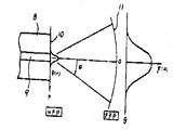
제2도는 NFP와 FFP의 관계를 모식적으로 표시한 도면.2 is a diagram schematically showing a relationship between NFP and FFP.
제3도는 스텝형 단일 모우드 파이버의 FFP의 계산예를 표시한 그래프.3 is a graph showing an example of calculating the FFP of a stepped single mode fiber.
제4도는 FFP 측정시의 최대 방사각을 바꾸었을 때의 스폿 사이즈의 계산 오차와 FFP 최소값과의 관계를 표시한 그래프로서, 제4(a)도는, 동최대 방사각을 바꾸었을때의 FFP 최소 파우어 값을 표시한 그래프 제4(b)도는 동 최대 방사각을 바꾸었을때의 스폿 사이즈 계산 오차를 표시한 그래프.4 is a graph showing the relationship between the calculation error of the spot size when the maximum radiation angle at the time of FFP measurement is changed and the minimum value of FFP. FIG. 4 (a) is the minimum FFP when the maximum radiation angle is changed. Graph showing the power value Figure 4 (b) shows the spot size calculation error when the maximum radiation angle is changed.
제5도는 본 발명 방법의 측정계 구성예를 표시한 도면.5 is a diagram showing an example of a measurement system configuration of the method of the present invention.
* 도면의 주요부분에 대한 부호의 설명* Explanation of symbols for main parts of the drawings
8 : 파이버 9 : 코어8: fiber 9: core
10 : 파이버의 출사 단부면 11 : FFP의 관측면10: exit end face of the fiber 11: observation face of the FFP
12 : 광원 13 : 광학계12 light source 13 optical system
14 : 피측정 파이버 15 : Ge-APD14 fiber to be measured 15 Ge-APD
16 : 신호 증폭부 17 : 계산기16: signal amplification unit 17: calculator
본 발명은 단일 모우드 파이버의 스폿 사이즈(혹은 모우드계 반경)의 측정 방법에 관한 것이다.The present invention relates to a method for measuring the spot size (or the mode radius) of a single mode fiber.
종래, 스폿 사이즈의 측정법은 여러가지 제안되어 있다. 그 하나는, 제1(a)에 표시한 바와같이, 광원(1)으로부터 광학계(2)를 개재해서 광파이버(3)에 측정광을 입사시켜서, 이 광파이버단에 있어서의 근단계 강도분포(Near Field Pattbrn : 이하 NFP라고 약칭함)를 직접 광학계(4) 및 적외선 비디콘 카메라(5)를 사용해서 측정하고 (측정예를 제1(b)도에 표시함), 어떤 정의식 예를들면, i) NFP가 최대값으로부터 1/e2으로 저하할때까지의 반경 방향 거리(ωo2)(단, e는 자연 개수의 밑) 혹은Conventionally, various methods of measuring the spot size have been proposed. One of them, as shown in the first (a), causes the measurement light to enter the
![]()
![]()
로써 정의되는 스폿 사이즈(ωo2)를 구하는 것이다.The spot size (ωo 2 ) defined as
(단 │R(γ)│2은 NFP, γ는 파이버 중심으로부터의 반경). 또한 도면중 (6)은 카메라 제어부, (7)은 계산기를 표시한다.(Where R (γ) 2 is NFP and γ is the radius from the fiber center). 6, a camera control part and 7 display a calculator.
그러나, 이 방법은 적외선 비디콘 카메라의 광전변화 특성의 비직선성이나 비디콘 감도의 불균일성에 의해서 측정 오차를 일으키기 쉽고, 또 광학계(5)로써 상을 확대하기 위한 렌즈계가 불가결하기 때문에 렌즈와 수차에 의한 측정오차도 피할 수 없고, 정밀도가 좋은 측정을 할 수 없는 결점이 있다. 한편 원방계 강도 분포(Far Field Pattern : 이하 FFP라고 약칭함)로 부터 스폿 사이즈를 구하는 방법으로써 간행물 "영국 전기학회 마이크로파 광파 음파저어널" (제 1 권, 13페이지, 1976년)에 기재된 갬블링들에 의한 방법이 알려져 있다. 그러나, 이 방법은 NFP가 가우스 분포라고 가정했을 경우의 간편법이고, 실제로 제조되는 단일 모우드 파이버의 NFP는 파이버 횡단면내의 굴절률 분포에 의해서 변화되어 가우스 분포로부터 벗어나는 일이 않기 때문에 커다란 측정 오차를 일으킬 위험이 있다. 또, 이 방법은 NFP를 직접 구하는 것이 아니므로 식 [1] 등으로 표시된 정의식으로 스폿 사이즈를 구할 경우에는 원리적으로 적용할 수 없다는 결점을 가지고 있다.However, this method is prone to measurement errors due to nonlinearity of photoelectric change characteristics of the infrared video camera, and nonuniformity of the sensitivity of the video camera, and since the lens system for enlarging an image with the
본 발명은 상기 종래의 결점을 제거하기 위하여 이루어진 것으로서, 이 때문에 본 발명은 단일 모우드 파이버의 파이버 단부로부터 방사된 광파의 원방계강도 분포를 그 최대값을 표시하는 방사각으로부터 25dB이상 저하되는 방사각까지의 범위에 걸쳐서 측정하고, 이 측정된 원방계 강도 분포로부터 한켈(Hankel) 변환을 이용해서 근단계 강도 분포를 계산하여, 이 근단계 강도 분포로부터 소정의 정의식에 의해 스폿 사이즈를 구함으로서 광전 변환특성의 비직선성이나 비디콘 감도의 불균일성등의 여러가지 문제점을 가진 적외선 비디콘 카메라나 수차가 문제로 되는 렌즈계를 사용하지 않고, 고정밀도의 측정을 가능하게 하고, 더우기 모든 스폿 사이즈의 정의식에도 적용가능하도록 한 것을 특징으로 한다.SUMMARY OF THE INVENTION The present invention has been made to eliminate the above-mentioned drawbacks. For this reason, the present invention provides a radiation angle of 25 dB or more lower than the radiation angle indicating the maximum value of the far-field intensity distribution of the light waves emitted from the fiber ends of the single-mode fiber. Measured over the range up to, photoelectric conversion by calculating the near-level intensity distribution using the Hankel transformation from the measured far-field intensity distribution, and obtaining the spot size from the near-level intensity distribution by a predetermined definition. High-precision measurement is possible without using an infrared video camera with various problems such as non-linearity of characteristics and non-uniformity of video sensitivity or aberration, and also applies to the definition of all spot sizes. It is characterized by making it possible.
이하, 본 발명의 구체적인 예에 대해서 설명한다.Hereinafter, specific examples of the present invention will be described.
단일 모우드 파이버의 NFP와 FFP의 전계분포의 함수는 키르히호프의 회절 이론을 이용하면 다음 식과 같이 표현된다.Using the Kirchhoff's diffraction theory, the function of the electric field distribution of NFP and FFP of a single mode fiber is expressed as
F(θ)α0R(γ)J0(Kr sinθ)rdr....................................[2]F (θ) α 0 R (γ) J 0 (Kr sinθ) rdr ... ...[2]
단, 여기서 F(θ),R(γ)는 각각 FFP, NFP의 전계분포 K=2π/λ (λ : 파장), (J0)는 0차의 베쎌함수, (θ)는 방사각을 표시한다.Where F (θ) and R (γ) are the electric field distributions K = 2π / λ (λ: wavelength) of FFP and NFP, respectively, (J 0 ) is the zeroth-order beam function, and (θ) is the emission angle. do.
이들 관계를 모식적으로 나타낸 것이 제2도이다. 또한 동도면에 있어서 (8)은 파이버, (9)는 코어, (10)은 파이버의 출사단부면, (11)은 FFP의 관측면을 표시한다.Fig. 2 schematically shows these relationships. In the same figure, 8 denotes a fiber, 9 denotes a core, 10 denotes an exit end face of the fiber, and 11 denotes an FFP observation plane.
상기 식[2]로부터 한켈 변환을 이용해서 다음 식이 유도된다.From the above equation [2], the following equation is derived using the Hankel transformation.
R(γ)α0F(θ)J0(Kr sinθ)sin 2θdθ............................[3]R (γ) α 0 F (θ) J 0 (Kr sinθ) sin 2θdθ ............ [3]
즉, F(θ)를 구함으로서 R(γ)을 구할 수가 있다.That is, R (γ) can be obtained by finding F (θ).
따라서, FFP인 │F(θ)│2을 측정함으로서 F(θ)가 구해지고, 식[3]을 이용함으로서 R(γ)이 구해지며 NFP인 │R(γ)│2이 계산에 의해 얻어지고, 이 NFP로부터 여러가지 정의에 의한 스폿 사이즈, 특히 식[1]로 정의되는 스폿 사이즈(![]()
![]()
단 FFP(│F(θ)│2)의 측정은 측정계의 수신 감도의 관게로부터 유한의 방사각(θ)의 범위에서 밖에 측정할 수가 없다.However , the measurement of FFP (| F (θ) | 2) can only be measured within the range of finite emission angle (θ) from the viewpoint of the reception sensitivity of the measurement system.
따라서 식 [3]으로부터 분명한 바와같이 R(γ) 즉 NFP(│R(γ)│2)는 완전히 역산할 수가 없다. 그래서 본 발명에서는 유한의 방사각(θ) 범위(0![]()
![]()
![]()
![]()
이 계산은 다음의 스칼라 파동 방정식This calculation is based on the scalar wave equation
![]()
![]()
에 의해 R(γ)을 구하고, 다시 상기 식[2]를 이용해서 F(θ)를 구함으로서 FFP(│F(θ)│2)를 얻을 수가 있다.F (? F (θ) | 2 ) can be obtained by obtaining R (γ) and F (θ) again using Equation [2].
이 제3도에서 FFP 측정 범위 0![]()
![]()
![]()
![]()
즉, 먼저 제3도에 표시된 값 θ에 대응하는 │F(θ)│2를 구하고, 이것으로부터 F(θ)를 구하며, 다시 상기 식[3]에 의해 R(γ)을 구하고, 이것으로부터 │R(γ)2│을 구하여, 이 (│R(γ)2│)을 정의식[1]에 대입해서 (ωο)를 구한다. 이 순서를 여러가지의 θmax 값에 대해서 행한다.That is, first, | F (θ) | 2 corresponding to the value [theta] shown in FIG. 3 is obtained, F (θ) is obtained from this, and R ([gamma]) is again obtained by the above formula [3], and from this | R (γ) 2 | is obtained and (ωο) is obtained by substituting this (│R (γ) 2 |) into the formula [1]. This procedure is performed for various θmax values.
한편, 스폿 사이즈의 엄밀한 값(ωο')는 상기 스칼라 파동 방정식 [4]에 의해 R(γ)을 구하고, 이것으로부터 │R(γ)2│을 구하며, 이 │R(γ)2│을 정의식 [1]에 대힙함으로서 얻어진다.On the other hand, the exact value (ωο ') of the spot size is obtained by obtaining the R (γ) from the scalar wave equation [4], obtaining R (γ) 2 from this, and defining this R (γ) 2 | It is obtained by facing [1].
제4(b)도는, 상기 θmax를 여러가지로 변화시킨 경우의 ωο를 엄밀한 값 ωο'와 비교해서 이것을 스폿 사이즈 계산 오차(%)로 표시한 것이다. 또, 제4(a)도는 θmax를 변화시킨 경우의 FFP의 상대 강도 최소값을 스폿 사이즈 계산 오차와 대응해서 표시한 것이다.In FIG. 4 (b), ωο in the case where the above θ max is changed in various ways is compared with the exact value ωο ', and this is expressed as a spot size calculation error (%). In addition, FIG. 4 (a) shows the relative intensity minimum value of FFP when θmax is changed in correspondence with the spot size calculation error.
이렇게해서 스폿 사이즈의 측정오차로써는 통상 약 ±2% 이내인 것이 필요하므로, 따라서 FFP로부터 스폿 사이즈를 역산할때에 발생하는 계산 오차는 약 2% 이내로 할 필요가 있다.In this way, the measurement error of the spot size usually needs to be within about ± 2%. Therefore, the calculation error generated when inverting the spot size from the FFP needs to be within about 2%.
제4(a)도에서 FFP의 최대치를 표시한 방사각으로부터 25dB이상 저하하는 방사각까지 범위에 걸쳐서 FFP를 측정함으로서, 스폿 사이즈의 계산 오차를 ±2%이내로 억제할 수 있음을 알 수 있다.It can be seen that the calculation error of the spot size can be suppressed within ± 2% by measuring the FFP from the radiation angle at which the maximum value of the FFP is shown in FIG.
제5도에 본 발명 방법에 의한 측정계의 구성예를 표시한다. 도면에 있어서, (12)는 광원, (13)은 광학계, (14)는 피측정 파이버, (15)는 Ge-APP, (16)은 신호 증폭부, (17)은 계산기를 각각 표시한다. 광원(12)으로써는 측정계의 다이나믹 레인지를 올리기 위하여, 가능한 한 고출력이며 또한 안정된 출력을 가진 광원을 사용하는 것이 바람직하고, 이러한 점에서 레이저 광원이 바람직하다. 광원으로써 반도체 레이저를 사용한 구성예에서는 36dB의 다이나믹 레인지를 얻을 수가 있었다. 계산기(17)에서는, 상술한 바와같이, FFP의 최대값을 나타낸 방사각으로부터 25dB이 이상 저하하는방사각까지의 범위에 걸친FFP(│F(θ)│2)로부터 F(θ)를 구하고, 식[3]에 의해 R(γ)을 구하고, 식[3]에 의해 R(γ)을 구하며 다시 NFP인 │R(γ)2│을 구하고, 또한 예를들면 식[1]과 같은 정의식을 이용해서 스폿 사이즈(ωο)를 계산한다.5 shows an example of the configuration of a measurement system according to the method of the present invention. In the drawing,
다음에, 본 발명의 측정예에 대해서 설명한다. 제 1 표는, 제1(a)도에 표시된 종래법에 의한 측정결과와 제5도에 표시된 본 발명의 구성예에 의한 측정 결과를 비교해서 표시한 것이다.Next, the measurement example of this invention is demonstrated. The 1st table compares and displays the measurement result by the conventional method shown in FIG. 1 (a), and the measurement result by the structural example of this invention shown in FIG.
이 측정에서는 2개의 단일 모우드 파이버의 스폿 사이즈를 각 측정법에 의해 각각 10회 측정하여, 그 평균값과 표준편차(σ)를 구했다. 제 1 표에서 명백한 바와같이 본 발명 방법에 의하면 종래법에 비해서 표준편차(σ)를 약 1/3∼1/4로 작게 할 수 있고, 측정 오차를 대폭 감소시킬 수 있는 것이 명백하다.In this measurement, the spot sizes of two single-mode fibers were measured 10 times by each measurement method, and the average value and standard deviation (?) Were obtained. As apparent from the first table, the method of the present invention makes it possible to reduce the standard deviation? To about 1/3 to 1/4 compared with the conventional method, and to significantly reduce the measurement error.
[제 1 표][Table 1]

이상과 같이, 본 발명에 의하면 광전변환 특성의 비직선성이나 비디콘 감도의 불균일성 등의 문제를 가진 적외선 비디콘 카메라나 수차가 문제가 되는 렌즈계를 필요로 하지 않으므로, 고정밀도의 측정이 가능하게 되고, 또한 NFP를 계산에 의해서 구하므로 어떠한 스폿 사이즈의 정의식에도 적용할 수 있다는 이점이 얻어진다.As described above, the present invention does not require an infrared video camera having problems such as nonlinearity of photoelectric conversion characteristics and nonuniformity of video sensitivity, or a lens system in which aberration is a problem, so that high-precision measurement is possible. In addition, since the NFP is obtained by calculation, an advantage can be obtained that can be applied to any spot size definition.
Claims (2)
Applications Claiming Priority (2)
| Application Number | Priority Date | Filing Date | Title |
|---|---|---|---|
| JP58181318A JPS6071934A (en) | 1983-09-29 | 1983-09-29 | Spot size measuring method of single mode fiber |
| JP58-181318 | 1983-09-29 |
Publications (2)
| Publication Number | Publication Date |
|---|---|
| KR850002319A KR850002319A (en) | 1985-05-10 |
| KR890001930B1 true KR890001930B1 (en) | 1989-05-31 |
Family
ID=16098580
Family Applications (1)
| Application Number | Title | Priority Date | Filing Date |
|---|---|---|---|
| KR1019840005865A KR890001930B1 (en) | 1983-09-29 | 1984-09-25 | The process of measurment of single mode fiber's spot size |
Country Status (6)
| Country | Link |
|---|---|
| EP (1) | EP0141251B1 (en) |
| JP (1) | JPS6071934A (en) |
| KR (1) | KR890001930B1 (en) |
| AU (1) | AU3363884A (en) |
| CA (1) | CA1213056A (en) |
| DE (1) | DE3466283D1 (en) |
Families Citing this family (5)
| Publication number | Priority date | Publication date | Assignee | Title |
|---|---|---|---|---|
| CA1245072A (en) * | 1985-11-05 | 1988-11-22 | Richard S. Lowe | Method and apparatus for measuring single mode fiber mode field radius |
| US5663798A (en) * | 1995-05-08 | 1997-09-02 | Dr. Khaled Karrai Und Dr. Miles Haines Gesellschaft Burgerlichen Rechts | Far-field characterization of sub-wavelength sized apertures |
| KR100434542B1 (en) * | 2001-09-18 | 2004-06-05 | 삼성전자주식회사 | Apparatus of measuring an aperture size of near-field optical probes and method thereof |
| JP5966672B2 (en) * | 2012-06-27 | 2016-08-10 | 住友電気工業株式会社 | Optical fiber measurement method |
| JP6705356B2 (en) * | 2016-10-12 | 2020-06-03 | 住友電気工業株式会社 | Optical fiber characteristic evaluation method and optical fiber characteristic evaluation apparatus |
Family Cites Families (3)
| Publication number | Priority date | Publication date | Assignee | Title |
|---|---|---|---|---|
| JPS5478156A (en) * | 1977-12-05 | 1979-06-22 | Hitachi Ltd | Detector of break point of optical fibers |
| DE2842316A1 (en) * | 1978-09-28 | 1980-04-17 | Siemens Ag | Optical fibre refractive index profile determination - using TV camera to scan light passing through end face of fibre |
| FR2514493A1 (en) * | 1981-10-12 | 1983-04-15 | Alard F | METHOD AND DEVICE FOR MEASURING THE EFFECTIVE DIAMETER OF THE GUIDE MODE IN A MONOMODE OPTICAL FIBER |
-
1983
- 1983-09-29 JP JP58181318A patent/JPS6071934A/en active Granted
-
1984
- 1984-09-25 KR KR1019840005865A patent/KR890001930B1/en not_active IP Right Cessation
- 1984-09-26 DE DE8484111473T patent/DE3466283D1/en not_active Expired
- 1984-09-26 EP EP84111473A patent/EP0141251B1/en not_active Expired
- 1984-09-28 AU AU33638/84A patent/AU3363884A/en not_active Abandoned
- 1984-09-28 CA CA000464304A patent/CA1213056A/en not_active Expired
Also Published As
| Publication number | Publication date |
|---|---|
| CA1213056A (en) | 1986-10-21 |
| JPH0317292B2 (en) | 1991-03-07 |
| KR850002319A (en) | 1985-05-10 |
| EP0141251A1 (en) | 1985-05-15 |
| AU3363884A (en) | 1985-04-18 |
| DE3466283D1 (en) | 1987-10-22 |
| JPS6071934A (en) | 1985-04-23 |
| EP0141251B1 (en) | 1987-09-16 |
Similar Documents
| Publication | Publication Date | Title |
|---|---|---|
| Anderson et al. | Spot size measurements for single-mode fibers-a comparison of four techniques | |
| Artiglia et al. | Mode field diameter measurements in single-mode optical fibers | |
| US10775541B2 (en) | Optical-fiber output beam profile measurement method and optical-fiber output beam profile measurement apparatus | |
| KR890001930B1 (en) | The process of measurment of single mode fiber's spot size | |
| Truax | Absolute interferometric testing of spherical surfaces | |
| Anderson et al. | Mode-field diameter measurements for single-mode fibers with non-Gaussian field profiles | |
| US4934819A (en) | Apparatus for measuring transverse moment of an electromagnetic field associated with an optical beam | |
| JPH05142097A (en) | Apparatus for measuring refractive index distribution | |
| Billington | Effective area of optical fibres definition and measurement techniques | |
| Ohashi et al. | Mode field diameter measurement conditions for fibers by transmitted field pattern methods | |
| Nilsson et al. | A microinterferometric method for analysis of rotation‐symmetric refractive‐index gradients in intact objects | |
| JPH05272920A (en) | Optical-fiber displacement gage | |
| JPH0439902B2 (en) | ||
| KR900007133B1 (en) | Laser scanner | |
| Kim et al. | Measurement of far-field and near-field radiation patterns from optical fibers | |
| Tomlinson et al. | Requirements And Measurement Techniques For GRIN-rod Lenses In Optical Fiber Components | |
| SU1620825A1 (en) | Method of micropositioning object | |
| Campos et al. | Characterization of single-mode fibers from wavelength dependence of modal field and far field | |
| JPH0293612A (en) | Mode conversion adapter | |
| GB2151351A (en) | Apparatus for checking optical fibres | |
| Di Vita et al. | Single-Mode Fibre Measurements and Standardization | |
| JPH04198822A (en) | Laser beam wavelength detection method and device | |
| JPS5815054B2 (en) | Excitation method of graded optical fiber | |
| Kim et al. | Measurement of far field radiation patterns from optical fibers | |
| Nobuyoshi | Hybrid Optical Processing for Measuring the Refractive Index Profile in Single-Mode Fibers |
Legal Events
| Date | Code | Title | Description |
|---|---|---|---|
| A201 | Request for examination | ||
| N231 | Notification of change of applicant | ||
| G160 | Decision to publish patent application | ||
| E701 | Decision to grant or registration of patent right | ||
| GRNT | Written decision to grant | ||
| FPAY | Annual fee payment |
Payment date: 19960517 Year of fee payment: 8 |
|
| LAPS | Lapse due to unpaid annual fee |