KR890001495B1 - Latch needle for a textile machine and method of producing same - Google Patents
Latch needle for a textile machine and method of producing same Download PDFInfo
- Publication number
- KR890001495B1 KR890001495B1 KR1019870000133A KR870000133A KR890001495B1 KR 890001495 B1 KR890001495 B1 KR 890001495B1 KR 1019870000133 A KR1019870000133 A KR 1019870000133A KR 870000133 A KR870000133 A KR 870000133A KR 890001495 B1 KR890001495 B1 KR 890001495B1
- Authority
- KR
- South Korea
- Prior art keywords
- needle
- latch
- hole
- shaft
- needle body
- Prior art date
Links
Images


Classifications
-
- D—TEXTILES; PAPER
- D04—BRAIDING; LACE-MAKING; KNITTING; TRIMMINGS; NON-WOVEN FABRICS
- D04B—KNITTING
- D04B35/00—Details of, or auxiliary devices incorporated in, knitting machines, not otherwise provided for
- D04B35/02—Knitting tools or instruments not provided for in group D04B15/00 or D04B27/00
- D04B35/04—Latch needles
Abstract
내용 없음.No content.
Description
제1도는 본 발명에 따른 래치 바늘의 부분 종단면도.1 is a partial longitudinal cross-sectional view of a latch needle according to the present invention.
제2도는 제1도의 따른 래치 바늘 A-B 선을 취한 확대 측단면도.2 is an enlarged side cross-sectional view of the latch needle A-B line according to FIG.
제3도는 제2도에 도시된 부품의 수정 실시예의 확대 단면도.3 is an enlarged cross-sectional view of a modified embodiment of the component shown in FIG.
제4도 내지 제7도는 제작중 네개의 연속 상태를 도시한 제1도의 A-B 선을 취한 확대 단면도.4 to 7 are enlarged cross-sectional views taken along the line A-B of FIG. 1 showing four continuous states during fabrication.
제8도 내지 제10도는 제작중 교체 제작방법을 세개의 연속 상태를 도시한 제1도의 A-B 선을 취한 확대 단면도.8 to 10 are enlarged cross-sectional views taken along line A-B of FIG. 1 showing three successive states of a replacement fabrication method during fabrication.
* 도면의 주요부분에 대한 부호의 설명* Explanation of symbols for main parts of the drawings
1 : 바늘 몸통 2 : 슬롯1: needle body 2: slot
4 바늘 래치 7 : 래치 몸통4 needle latch 7: latch body
9 : 피봇 축 11 : 축 스텃9
20 : 후크 120 : 원통형 볼트20
본 발명은 바늘 몸통의 긴 슬롯내에서 선회할 수 있고 한 연속 베어링 구멍에 의해 두개의 동축인 축 스텃상에 선회 가능하도록 탑재된 래치를 포함하는 방직 기계용 래치 바늘에 관한 것이다. 축 스텃은 긴 슬롯에 측면적으로 제한되는 비늘 몸통 측면에 설치되고 긴 슬롯안에 돌출된다. 본 발명은 또한 이러한 래치 바늘을 제조하는 방법에 관한 것이다.The present invention relates to a latch needle for a weaving machine comprising a latch that can pivot within an elongated slot of the needle body and is pivotably mounted on two coaxial shaft swabs by one continuous bearing hole. The axial swab is installed on the side of the scale body which is laterally limited to the long slot and protrudes in the long slot. The invention also relates to a method of making such a latch needle.
이러한 형식의 래치 바늘은 특히, 편물기와 예를 들면, 특수 재봉틀 등의 여러가지 방직기계에서 광범위하게 사용된다. 실제로 이러한 래치 바늘은 긴 슬롯내에 측면으로 돌출된 두개의 축 스텃을 가지며, 래치 바늘은 두개의 바늘 몸통 측면이 압축된 부품에 의해 형성되고, 바늘 몸통 측면상에 한 몸체로 형성된 베어링 핀과 같은 방법으로 래치 구멍에서 변형된다.This type of latch needle is particularly widely used in knitting machines and various textile machines such as, for example, special sewing machines. In practice, such a latch needle has two axial swabs projecting laterally in a long slot, and a latch needle is formed by a component in which two needle body sides are compressed, and a method of bearing pin formed as a body on the needle body side. Deformed from the latch hole.
이러한 형식의 래치 베어링을 가지는 래치 베어링의 예는 예를 들면, 미합중국 특허 제3,934,109호와 영국 특허 제836,297호에 설명되어 있다.Examples of latch bearings having latch bearings of this type are described, for example, in US Pat. No. 3,934,109 and UK Pat. No. 836,297.
두개의 베어링 핀이 서로 견고히 연결되어 있지 않고 래치 구멍에서 래치 구멍의 전면판과 거의 접촉하는 사실에 따라 래치 베어링은 바늘 몸통 측면내의 파손 발생 감소라는 측면에서 보면 어느 정도의 탄력을 가지는 것을 양호하다는 것을 발견하게 된다. 그러나, 실제에 있어서, 래치 구멍내에서 설치된 측면의 재질은 예견할 수 없는 유동 움직임에 따라 몸통 스텃의 이론적인 원통 형상으로부터 비롯되는 크거나 또는 작은 편차가 되도록 래치 구멍의 형상에 불완전하게 적용되도록 성형할 수 밖에 없다. 비록 공장으로부터 방금 받은 래치 바늘일지라도 베어링 핀상의 래치 구멍의 단위 표면적당 하중은 베어링 핀이 바늘 몸통 측면에 이 구멍을 통하여 엠보싱 방법으로 형성되었기 때문에 비교적 작다. 사용기간의 증가에 따라, 두개의 베어링 핀상에서 유동하는 래치 베어링의 래치 안내부면 상에 발생하는 마모의 결과로 발생하는 바늘의 기능 장해의 위험은 이들이 원통형 형상에 대응하여 매우 불완전하게 성형되어서 래치의 폐쇄운동 동안에 래치의 자유단부에 연장되는 것이 증가하여 측면상에서 바늘 후크 또는 슬라이드가 떨어져 잃어버리게 되며 따라서 바늘은 못쓰게 된다.Due to the fact that the two bearing pins are not firmly connected to each other and almost contact the front plate of the latch hole at the latch hole, it is preferable that the latch bearing has a certain degree of elasticity in terms of reducing the occurrence of breakage in the needle body side. You will find it. In practice, however, the material of the side installed in the latch hole is shaped to be incompletely applied to the shape of the latch hole so that there is a large or small deviation resulting from the theoretical cylindrical shape of the trunk spool as unpredictable flow movements. Have no choice but to. Although the latch needle just received from the factory, the load per unit surface area of the latch hole on the bearing pin is relatively small because the bearing pin is formed by embossing through this hole on the side of the needle body. As the service life increases, the risk of needle failure as a result of wear occurring on the latch guide surface of the latch bearing flowing on the two bearing pins is that they are very incompletely shaped corresponding to the cylindrical shape so that the latch The extension to the free end of the latch during the closing movement increases, causing the needle hook or slide to fall off and lose on the side, thus causing the needle to wear out.
미합중국 특허 제3,394,109호는 몸통 측면으로부터 성형된 재질로부터 축 스텃을 형성한 천공 베어링 핀의 전면판을 용접, 예를 들면, 고초점 레이저 광선에 의한 용접을 포함하는 이러한 문제점에 대한 방법을 설명하고 있다. 그러나, 이 방법은 이러한 문제를 극복하지 못했다. 이러한 문제는 래치 바늘이 고속 운전 편물기 또는 튼튼한 생사를 편물하는데 사용된다면 매우 중대한 문제가 되는데 즉, 래치 베어링은 래치 안내부의 정밀도 뿐만 아니라 기계적 강도도 또한 매우 높은 요구 조건에 맞아야만 한다.U.S. Patent No. 3,394,109 describes a method for this problem, including welding the face plate of a pierce bearing pin with an axial swab from a material molded from the body side, for example welding with a high focus laser beam. . However, this method did not overcome this problem. This problem is very important if the latch needle is used to knit a high speed driving knitting machine or sturdy green yarn, ie the latch bearing must meet very high requirements as well as the precision of the latch guide.
공지된 다른 래치 바늘은 예를 들면, 독일연방공화국 특허 제1,296,743호에는 래치 베어링이 한 몸체로 형성되고, 원통형 축 또는 볼트는 바늘 몸통의 긴 슬롯을 횡단하고 바늘 몸통 측면의 대응 동축 구멍내의 두개의 단부상에 놓이고 축 측면에 나사 또는 레어저 용접에 의해 그곳에 단단히 연결된다. 비록 래치 바늘에 매끄러운 축 볼트에 면하는 원통형 재킷이 정밀하게 가공되었기 때문에 몸통 측면에 대응되는 횡단 구멍에 삽입되도록 분리 제작되고 정밀한 원통형인 연속 축볼트상에 장착된 래치는 정밀도와 내마모성에 대한 우수한 래치 안내부를 가지고 있다고 하더라도 이러한 래치 바늘은 래치 베어링 배열에 작용하는 연속 축 볼트가 단단하고 바늘의 대칭축에 완전히 비탄력적이기 때문에 오늘날 그 중요성은 거의 없다. 이러한 피할수 없는 원인은 바늘이 높은 응력 특히, 동적인 응력을 받을 때 바늘 몸통 측면이 파손되고 따라서, 이러한 바늘의 사용 수명은 바람직하지 않게 제한된다.Other known latch needles are described, for example, in German Patent No. 1,296,743 with latch bearings in one body, cylindrical shafts or bolts traversing long slots in the needle body and two in corresponding coaxial holes on the side of the needle body. It is placed on the end and securely connected thereto by screw or laser welding on the side of the shaft. Although a cylindrical jacket facing the smooth shaft bolts on the latch needle has been precisely machined, the latches, which are separately manufactured for insertion into the transverse holes corresponding to the body side and mounted on a precision cylindrical continuous shaft bolt, are excellent latches for precision and wear resistance. Even with guides, these latch needles are of little importance today because the continuous shaft bolts acting on the latch bearing arrangement are rigid and completely inelastic to the axis of symmetry of the needle. This inevitable cause is that the needle body side breaks when the needle is subjected to high stress, especially dynamic stress, and thus the useful life of such needle is undesirably limited.
부가적으로, 독일연방공화국 특허 제215,749호는 축 볼트와 관련된 바늘 몸통 측면의 빈 구멍내의 한 측면상에 장착되는 것과 축 볼트를 대응 바늘 몸통 측면의 횡단 구멍내의 다른 측면상에 용접에 의해 고정시키는 것이 설명되어 있다. 비록 바늘 몸통 측면이 래치 베어링내에서 어느 정도의 탄성의 구비되어 이러한 바늘을 제작하는데 비싸므로 이 때문에 대량 생산에 적합하지 않다는 사실은 별 문제로 하고라도 이러한 탄성은 제한적이다.Additionally, Federal Republic of Germany Patent No. 215,749 is mounted on one side in the hollow hole on the side of the needle body associated with the shaft bolt and the welding of the shaft bolt on the other side in the transverse hole on the side of the corresponding needle body by welding. Is described. Although the needle body side has some elasticity in the latch bearings and is expensive to manufacture such needles, the fact that it is not suitable for mass production because of this is limited.
그러므로, 본 발명의 목적은 경제적으로 대량 생산할 수 있고 뛰어난 내마모성과 긴 사용기간에 걸쳐 전유용성을 보유하도록 래치가 꼭 맞는 베어링 유격과 동시에 바늘 몸통 측면의 파손 발생 위험을 제거 또는 최소로 줄이는 래치 바늘을 제공하는 데 있다.Therefore, it is an object of the present invention to provide a latch needle that economically mass-produces and which eliminates or minimizes the risk of occurrence of breakage on the side of the needle body at the same time as the latch fits snugly to provide excellent wear resistance and overall utility over long service life. To provide.
본 발명의 상기 목적과 다른 목적의 달성은 각각의 축 스텃이 분리 원통형 볼트의 형상을 갖고 관련된 바늘 몸통 측면내의 연속 구멍을 통하여 꼭 맞게 적합하게 맞춰져 삽입되고 전위에 대항하여 고정되도록 이 구멍내에 고정되는 래치를 제공하는데 있다.Achieving the above and other objects of the present invention is that each axial swab has the shape of a separate cylindrical bolt and is secured in this hole such that it is properly fitted and inserted through a continuous hole in the associated needle body side and fixed against dislocations. To provide a latch.
긴 슬롯의 나비에 정확히 맞춰지는 래치 축과 협동하는 두 축 스텃의 재킷면이 매끄럽고 정확하게 원통형이기 때문에 베어링 축과 래치 구멍사이의 단위 면적당 최대 허용 하중이 생기게 되므로 단위 면적당 특정 피봇 베어링 하중을 최소화하여 래치 베어링의 내마모성을 증가시키는 결과가 된다. 래치 구멍의 직경은 바늘 몸통 스텃에 접근하도록 만들어 질 수 있기 때문에 래치 구멍의 직경은 변하지 않으며 예를 들면 +0.001㎜의 직경 차이로 방사상 방향은 물론이고 축방향으로 래치 베어링을 매우 타이트한 유격을 가능하게 해준다. 따라서, 래치는 비록 장기간 동안 사용후일지라도 매우 정밀하게 안내되므로 래치의 선회 운동은 바늘의 대칭축으로부터 알아차릴 만큼 편차가 나지 않을 것이므로 래치는 폐쇄 과정중에 후크상에 신뢰할 수 있게 위치된다. 두 축 스텃이 두축 스텃에 인접한 전면판에 서로 연결되어 있지 않기 때문에 또 래치 베어링이 동시에 바늘의 대칭축을 횡단하는 매우 많은 탄성을 가지고 있기 때문에 바늘 몸통 측면의 파손은 영구히 방지된다. 래치 구멍내의 축 스텃의 인접 전면판 사이의 축방향 유격은 적어도 약 0.01㎜는 되어야만 한다. 그러나, 어떤 두께보다 적은 바늘, 래치 베어링의 충분한 탄성은 만약에 두 축 스텃의 축 스텃의 인접 전면판에 서로 접하도록 배열되어 있다면 또한 주어짐이 실험에서 보여준다.Since the jacket face of the two shaft spans, cooperating with the latch axis that exactly fits into the long slot butterfly, is smooth and precisely cylindrical, there is a maximum allowable load per unit area between the bearing axis and the latch hole, minimizing the specific pivot bearing load per unit area. This results in increased wear resistance of the bearings. Since the diameter of the latch hole can be made to approach the needle trunk swab, the diameter of the latch hole does not change and, for example, a +/- 0.001 mm diameter difference allows for very tight clearance of the latch bearing in the axial direction as well as in the radial direction. Let's do it. Thus, since the latch is guided very precisely even after long term use, the latch's pivoting motion will not deviate noticeably from the axis of symmetry of the needle, so the latch is reliably positioned on the hook during the closing process. Since the two axial swabs are not connected to each other on the faceplate adjacent to the two axial swabs and because the latch bearings have so much elasticity that traverses the axis of symmetry of the needle at the same time, the breakage of the needle body side is permanently prevented. The axial play between adjacent faceplates of the axial swabs in the latch holes should be at least about 0.01 mm. However, it is also shown in the experiment that a needle less than a certain thickness, sufficient elasticity of the latch bearing is also given if it is arranged in contact with each other on the adjacent faceplate of the shaft span of the two shaft spans.
오히려, 두 축 스텃은 축 스텃의 전면판 부근내의 구멍에 고정되고 이 전면판은 이 목적을 위해 예를 들면, 긴 슬롯으로부터 멀리 떨어져서 바늘 몸통 측면에 특히, 레이저 용접에 의해 용접된다. 그러나, 축 스텃은 구멍을 둘러싸는 각각의 바늘 몸통 측면의 재질의 변형에 의해 고정되고 이러한 변형이 구멍내로 돌출되는 것이 특히 유리하다는 것을 발견하게 된다. 이러한 변형은 종래의 엠보싱 방법에 의해 제조될 수 있다.Rather, the two shaft swabs are fixed in a hole in the vicinity of the faceplate of the shaft swab and this faceplate is welded for this purpose, for example by laser welding, in particular on the needle body side away from the long slot. However, the axial swabs are fixed by deformation of the material of the side of each needle body surrounding the hole, and it is found that it is particularly advantageous for this deformation to protrude into the hole. Such modifications can be made by conventional embossing methods.
장치에서 축 스텃은 긴 슬롯에 인접한 바늘 몸통 측면 구멍의 근처에만 장착될 수 있고 구멍 길이의 약 절반까지 연장되며 이 때문에 구멍의 잔류 자유부분은 축 스텃을 고정하기 위해 사용 가능하다.In the device, the shaft swab can only be mounted in the vicinity of the needle body side hole adjacent to the long slot and extends to about half the length of the hole so that the remaining free portion of the hole can be used to secure the shaft swab.
본 발명의 실시예에서 환형 비드의 재질은 긴 슬롯으로부터 멀리 떨어져 면하는 각 축 스텃의 단부 근처에 설치된다. 이 환형 비드는 구멍을 둘러싸고 있는 바늘 몸통 측면의 재질로부터 성형되고 구멍의 자유부분내로 연장된다. 환형 비드는 관련된 축 스텃의 인접 외부 전면판으로부터의 거리에 설치되며 이 때문에 래치 운동의 영향하에서 구멍의 탈선으로부터 축 스텃을 방지한다. 그러나 어떤 경우에도 환형 비드는 래치 베어링의 탄성에 방해 없이 확실히 위치된다.In an embodiment of the invention the material of the annular bead is installed near the end of each axial swab facing away from the elongated slot. This annular bead is formed from the material on the side of the needle barrel surrounding the hole and extends into the free portion of the hole. The annular beads are installed at a distance from the adjacent outer faceplate of the associated axial swabs, thereby preventing the axial swabs from deviation of the holes under the influence of the latch movement. In any case, however, the annular bead is reliably positioned without disturbing the elasticity of the latch bearing.
본 발명에 따라서 이러한 래치 바늘은 슬롯이 없는 바늘 몸통을 가지고 시작하여 처음으로 바늘 몸통에 래치의 피봇축과 동축인 횡단 구멍을 만들고, 연속 원통형 볼트를 횡단 구멍내에 꼭 맞춰지도록 삽입되고 그 다음에 긴 슬롯은 볼트의 작용에 의해 바늘 몸통에서 작동되도록 특히, 간단하고 경제적이며 정밀하게 제조될 수 있다. 긴 슬롯내에 래치를 삽입한 후 두 바늘 몸통 측면내에 남아 있는 볼트 부분은 래치 베어링 구멍의 양 측면내에 긴 슬롯을 측면을 제한하는 축 스텃으로써 삽입되고 전위에 대항하여 고정되도록 바늘 몸통 측면의 구멍내에 최종적으로 고정된다.According to the invention, such a latch needle starts with a slotless needle body and first makes a transverse hole coaxial with the pivot axis of the latch in the needle body and is inserted so that a continuous cylindrical bolt fits snugly within the transverse hole and then is elongated. The slot can be manufactured in particular simply, economically and precisely to be operated in the needle barrel by the action of the bolt. The part of the bolt remaining in the two needle body sides after the latch is inserted into the long slot is inserted into the side of the needle bearing hole by the axial swab restricting the long slot in both sides of the latch bearing hole and finally in the hole in the needle body side to be fixed against the dislocation. Is fixed.
볼트가 횡단 구멍에 삽입되어 후에 형성된 긴 슬롯 나비의 거의 절반에 대응하는 길이에 의해 바늘 몸통의 양측면을 지나서 돌출될 것이다. 베어링 구멍내에 볼트 부재를 삽입한 후 볼트 부재는 바늘 몸통의 외부 측면과 실제적으로 동일 평면이 된다. 두개의 볼트 부재는 이에 맞는 길이를 또한 가질 수 있고 압축기구에 의해 삽입되는데 이것은 각각의 바늘 몸통 측면 구멍내에 놓여 있는 볼트 부재의 외부 전면판이 삽입된 상태에서 바늘 몸통 측면 구멍내에 맞춰져 있다. 볼트 부재를 고정하기 위하여 바늘 몸통 측면의 구멍을 둘러싸는 바늘 몸통 측면의 재질이 소성 변형되고 본 발명의 양호한 실시예에서 바늘 몸통 측면의 재질은 관련된 볼트 부재의 인접 외부 전면판으로부터 축방향의 거리까지 가능하도록 각각의 구멍내에 연장되는 환형 비드내에서 변형된다.The bolt will be inserted into the transverse hole and protrude past both sides of the needle barrel by a length corresponding to almost half of the long slot butterfly formed later. After inserting the bolt member into the bearing hole, the bolt member is substantially coplanar with the outer side of the needle barrel. The two bolt members may also have a length corresponding thereto and are inserted by the compression mechanism, which is fitted in the needle body side hole with the outer faceplate of the bolt member lying in each needle body side hole inserted. In order to secure the bolt member, the material of the needle body side surrounding the hole of the needle body side is plastically deformed and in a preferred embodiment of the invention the material of the needle body side is axially distanced from the adjacent outer faceplate of the associated bolt member. It is deformed in annular beads extending in each hole so as to be possible.
제1도에 도시된 래치 바늘은 바늘의 한 단부에 형성된 후크(20)와 예를 들면, 편물기에서 사용되는 공지의 잠금부재에 의해 제어되는 바늘과 적어도 하나의 다리(자세히 도시되지 않음)를 가질 수 있는 바늘 몸통(1)을 포함하고 있다. 바늘의 종축과 대칭인 긴 슬롯(2)은 바늘 몸통(1)내에 내재해 있고 바늘의 하부 에지쪽으로 보푸라기를 배출하도록 바늘 몸통의 하부 에지내의 통로(3)에 대하여 열려 있다. 래치 몸통을 구비한 바늘 래치(4)는 슬롯(2)내에 선회 가능하도록 수용되어 있다. 도시된 폐쇄위치에서 바늘 래치(4)의 무딘 단부(5)는 바늘의 팁(6)을 덮고 있다. 무딘 단부(5)로부터 떨어져 면한 래치의 단부 근처에 바늘 래치(4)는 연속 원통형 베어링 구멍(8)이 구비되어 있어서 바늘 래치(4)는 선회 가능하도록 탑재된다. 횡단 연장 피봇 축(9)이 참조번호(9)로 도시되어 있다.The latch needle shown in FIG. 1 comprises a needle and at least one leg (not shown in detail) controlled by a hook 20 formed at one end of the needle and, for example, a known locking member used in a knitting machine. It includes a needle body (1) that can have. The long slot 2, which is symmetric to the longitudinal axis of the needle, is inherent in the
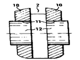
제2도 및 제3도에 도시된 바와 같이, 각각 측면으로 긴 슬롯(2)을 제한하는 바늘 몸통 측면(10)의 하나는 피봇축(9)과 동축인 원통형 구멍을 구비한다. 분리 원통형 볼트의 형태인 축 스텃(12)은 각각의 구멍(11)에 단단히 삽입되고 래치 몸통(7)의 베어링 구멍(8)내에 끼워지고 긴 슬롯(2)내에 돌출되도록 압축하여 맞춘다. 두개의 동축 원통형 축 스텃(12)은 그들끼리 축방향으로 이격되고 이들이 적어도 0.01㎜의 갭(13)이 형성되도록 평행 전면판과 면하게 된다.As shown in FIGS. 2 and 3, one of the
두개의 동축 원통형 축 스텃(12)의 매끄러운 재킷면상에서 래치 몸통(7)의 베어링 구멍(8)은 약간의 유격이 있게 장착되고, 축 스텃과 베어링 구멍(8) 사이는 +0.001㎜나 그 이하의 직경의 차이가 있다. 래치 몸통(7)은 긴 슬롯(2)에 형성된 바늘 몸통 측면(10)과의 사이는 약간의 유격을 가지고 정밀하게 안내된다.On the smooth jacket face of the two coaxial cylindrical shaft swims 12 the bearing bore 8 of the
두개의 원통형 축 스텃(12)은 전위에 대항하여 고정되도록 하기 위하여 바늘 몸통 측면(10)에 연관된 각각의 구멍(11)에 고정되어 있다.Two cylindrical shaft swims 12 are secured to
제2도의 실시예에서, 축 스텃(12)은 구멍의 약 절반이 바깥쪽으로 긴 슬롯(2)으로부터 연장된 바늘 몸통 측면(10)의 구멍(11)의 부근에만 장착된다. 변형부(14)는 구멍(11)을 둘러싼 곳의 각각의 바늘 몸통 측면(10)의 재질로 만들어지고, 이들 변형부는 축 스텃(12)이 바늘 몸통 측면(10)의 바깥쪽으로의 축방향 전위를 방지하기 위하여 환형 비드의 형상을 갖는 것이 양호하다. 환형 비드 대신에 구멍(11)내에 돌출된 개개의 핑거 또는 투쓰와 같은 융기부나 몸통 측면의 재질로 대응하는 변형부를 고정수단으로써 또한 구비할 수도 있다.In the embodiment of FIG. 2, the
변형부에서 환형 비드 또는 대응 융기부나 변형부는 각각의 인접 축 스텃(12)의 외부 전면판의 인접한 곳에서 직접 제2도에 도시된 바와 같이 설치될 수 있다. 그러나, 그 배열은 각각의 비드(14)와 제2도에서 점선(12a)으로 전개된 인접한 외부 전면판 사이에 존재하는 축방향의 길이와 같이 배열되는 것이 양호할지도 모른다.The annular beads or corresponding ridges or deformations in the deformable portion can be installed as shown in FIG. 2 directly in the vicinity of the outer faceplate of each adjacent
제3도에 따른 실시예는 본질적으로 제2도의 실시예와 같다. 그러므로, 같은 부품은 동일한 도면부호가 주어지고 같은 부품은 다시 설명하지 않기로 한다. 제2도에 따른 실시예와의 비교로, 동축인 두개의 원통형 축스텃(12)은 연관된 구멍에 용접에 의해 양호하게는 레이저 빔에 의해 고정된다. 용접 접합부 또는 용접 위치(15)는 도면부호로 표시되어 있다.The embodiment according to FIG. 3 is essentially the same as the embodiment of FIG. 2. Therefore, the same parts are given the same reference numerals and the same parts will not be described again. In comparison with the embodiment according to FIG. 2, two
제1도에 따른 래치 바늘은, 래치 베어링의 관계에 대하여 제4도 내지 제7도 또는 제8도 내지 제10도에 도시된 조금 변경된 방법으로 특히 간단하고 정밀한 방법으로 제조될 수 있다.The latch needle according to FIG. 1 can be manufactured in a particularly simple and precise manner in a slightly modified manner as shown in FIGS. 4 to 7 or 8 to 10 with respect to the relationship of the latch bearing.
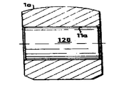
슬롯을 아직 갖지 않은 바늘 몸통(1)을 갖는 바늘 반제품은 제4도 내지 제8도에 도시된 바와 같이 래치의 피봇 축(9)과 동축인 원통형 구멍(11a)을 바늘 몸통(1a)내에 예를 들면 천공에 의해 처음으로 가공을 시작하게 된다. 구멍(11a)의 직경은 후에 가공된 두개의 축 스텃(12)의 직경과 같다. 원통형 볼트(120)(제5도 참조) 또는 원통형 볼트(120a)(제18도 참조)는 그 다음에 바늘 몸통(1a)의 두께와 제8도에서 바늘 몸통(1a) 두께의 약 1.25배의 두께로 대응하는 제5도의 볼트의 길이로 연속 구멍(11a) 내에 단단히 압축 고정된다. 따라서 제5도에서, 삽입된 원통형 볼트(120)는 바늘 몸통(1a)의 측면과 동일 평면이며 한편, 제8도에서의 원통형 볼트(120)는 대응되는 양에 의해 바늘 몸통(1a)의 측면 이상 돌출되어 있으나 후에 형성된 긴 슬롯(2)의 절반의 넓이에 해당한다.A needle semifinished product having a
제6도 및 제9도에 따라서, 그 다음에 긴 슬롯은 바늘 몸통내에 깎여지고 원통형 볼트(120, 120a)가 동시에 깎여서 두개의 축 스텃(12)으로 세분된다.According to FIGS. 6 and 9, the long slot is then cut into the needle barrel and the
바늘 래치(4)의 래치 몸통(7)은 베어링 구멍(8)이 피봇 축(9)과 동축이 되게 하기 위하여 긴 슬롯(2)에 삽입되고 그래서 두개의 원통형 볼트는 두개의 축 스텃(12)을 형성하여 바늘의 대칭 평면에 대하여 양측면으로부터 축방향으로 전진되고 이에 의해 래치 몸통(7)의 베어링 구멍(8)내로 들어간다. 삽입된 상태에서, 두개의 축 스텃(12)은 전에 설명한 갭(13)(제2도 참조)에 의해 서로 조금 이격되거나 교체적으로 축 스텃의 전면판에서 서로 대향하여 또는 놓일 수도 있다.The
한편 제8도 내지 제10도에 따른 실시예에서, 두개의 축 스텃의 바깥쪽으로 향한 전면판은 삽입된 상태에서, 바늘 몸통(제10도 참조)의 측면과 동일 평면이 되고, 제4도 내지 제7도에 따른 실시예에서, 축 스텃(12)은 각각의 구멍(11)에 장착된 두개의 축 스텃(12)의 외향된 전면판과 같이 구멍(11)안에 끼워진 압축 도구(도시되지 않음)에 의해 삽입되고 대응하는 긴 슬롯(2) 넓이의 약 절반 넓이에 상당하는 거리로 연장되어 있다.On the other hand, in the embodiment according to FIGS. 8 to 10, the outwardly facing front plate of the two axial swabs is coplanar with the side of the needle barrel (see FIG. 10) in the inserted state, and FIGS. In the embodiment according to FIG. 7, the
최종적으로, 두개의 삽입된 축 스텃(12)은 융기된 환형 비드(14) 또는 용접의 한 수단에 의해 제2도 및 제3도에 도시된 방법으로 고정되고, 측면의 바늘 측면(10)의 구멍(11)의 변위에 대항하여 고정되도록 하기 위하여 긴 슬롯(2)에 의해 서로 분리되어 있다.Finally, the two inserted
본 설명은 1986년 1월 11일 출원된 독일연방공화국 특허 제3600620; 3호에 설명된 주제와 관련되고 전 명세서가 본원에 참조로써 인용되어 있다.This description is of the Federal Republic of Germany Patent No. 3600620, filed January 11, 1986; Regarding the subject matter described in No. 3, the entire specification is incorporated herein by reference.
본 발명의 상기 설명에 여러 가지 변형, 변화 및 적용을 하여도 이해될 것이고 첨부된 특허청구의 범위와 동등한 범위와 의미가 이해되도록 의도되었다.Various modifications, changes, and adaptations to the above description of the invention are to be understood and are intended to be understood as the scope and meaning equivalent to the scope of the appended claims.
Claims (16)
Applications Claiming Priority (2)
| Application Number | Priority Date | Filing Date | Title |
|---|---|---|---|
| DE3600620.3 | 1986-01-11 | ||
| DE3600620A DE3600620C1 (en) | 1986-01-11 | 1986-01-11 |
Publications (2)
| Publication Number | Publication Date |
|---|---|
| KR870007322A KR870007322A (en) | 1987-08-18 |
| KR890001495B1 true KR890001495B1 (en) | 1989-05-04 |
Family
ID=6291679
Family Applications (1)
| Application Number | Title | Priority Date | Filing Date |
|---|---|---|---|
| KR1019870000133A KR890001495B1 (en) | 1986-01-11 | 1987-01-10 | Latch needle for a textile machine and method of producing same |
Country Status (8)
| Country | Link |
|---|---|
| US (1) | US4747277A (en) |
| EP (1) | EP0231435B1 (en) |
| JP (1) | JPS62162057A (en) |
| KR (1) | KR890001495B1 (en) |
| CN (1) | CN1004561B (en) |
| CA (1) | CA1269857A (en) |
| DE (2) | DE3600620C1 (en) |
| ES (1) | ES2012333B3 (en) |
Families Citing this family (8)
| Publication number | Priority date | Publication date | Assignee | Title |
|---|---|---|---|---|
| DE3800802C1 (en) * | 1988-01-14 | 1989-02-16 | Theodor Groz & Soehne & Ernst Beckert Nadelfabrik Kg, 7470 Albstadt, De | |
| JPH0265731U (en) * | 1988-11-08 | 1990-05-17 | ||
| DD284925A5 (en) * | 1989-06-12 | 1990-11-28 | ��������@��������@����������@���k�� | LATCH NEEDLE |
| US5697773A (en) * | 1994-08-23 | 1997-12-16 | Denticator International, Inc. | Rotary fluid reaction device having hinged vanes |
| DE10341630B4 (en) * | 2003-09-10 | 2006-11-16 | Groz-Beckert Kg | latch needle |
| EP2224048B1 (en) * | 2009-02-26 | 2011-08-31 | Groz-Beckert KG | Latch needle with rotating axle pin |
| EP2604359B1 (en) * | 2011-12-14 | 2017-06-14 | Groz-Beckert KG | Latch needle with improved latch bearing and its method of manufacturing |
| CN112251903A (en) * | 2020-09-28 | 2021-01-22 | 宋悦 | Knitting needle structure of textile machine |
Family Cites Families (10)
| Publication number | Priority date | Publication date | Assignee | Title |
|---|---|---|---|---|
| DE215749C (en) * | ||||
| DE608619C (en) * | 1935-01-28 | Torrington Co | Method of manufacturing knitting machine needles | |
| US1794309A (en) * | 1922-09-30 | 1931-02-24 | Marx Richard | Knitting needle and method of making same |
| US1961624A (en) * | 1931-06-15 | 1934-06-05 | Torrington Co | Latch needle and method of making the same |
| GB836297A (en) * | 1958-01-23 | 1960-06-01 | Torrington Co | Improvements in or relating to bearings for latch knitting needles |
| GB1142409A (en) * | 1966-06-21 | 1969-02-05 | Groz & Soehne Theodor | A latch needle for knitting machines |
| DE1296734B (en) * | 1967-12-18 | 1969-06-04 | Groz & Soehne Theodor | Latch needle for knitting machines |
| DE1906892A1 (en) * | 1969-02-12 | 1970-05-14 | ||
| US3850011A (en) * | 1972-06-23 | 1974-11-26 | Torrington Co | Latch pivot for latch needle |
| US3934109A (en) * | 1972-06-23 | 1976-01-20 | The Torrington Company | Latch pivot for latch needle |
-
1986
- 1986-01-11 DE DE3600620A patent/DE3600620C1/de not_active Expired
- 1986-10-17 DE DE8686114373T patent/DE3668334D1/en not_active Expired - Lifetime
- 1986-10-17 ES ES86114373T patent/ES2012333B3/en not_active Expired - Lifetime
- 1986-10-17 EP EP86114373A patent/EP0231435B1/en not_active Expired - Lifetime
-
1987
- 1987-01-05 CN CN87100050.4A patent/CN1004561B/en not_active Expired
- 1987-01-06 US US07/000,881 patent/US4747277A/en not_active Expired - Lifetime
- 1987-01-09 CA CA000527002A patent/CA1269857A/en not_active Expired - Fee Related
- 1987-01-09 JP JP62001969A patent/JPS62162057A/en active Granted
- 1987-01-10 KR KR1019870000133A patent/KR890001495B1/en not_active IP Right Cessation
Also Published As
| Publication number | Publication date |
|---|---|
| CN87100050A (en) | 1987-07-22 |
| EP0231435A1 (en) | 1987-08-12 |
| EP0231435B1 (en) | 1990-01-17 |
| US4747277A (en) | 1988-05-31 |
| JPH0253539B2 (en) | 1990-11-19 |
| DE3668334D1 (en) | 1990-02-22 |
| KR870007322A (en) | 1987-08-18 |
| CA1269857A (en) | 1990-06-05 |
| ES2012333B3 (en) | 1990-03-16 |
| DE3600620C1 (en) | 1987-02-12 |
| JPS62162057A (en) | 1987-07-17 |
| CN1004561B (en) | 1989-06-21 |
Similar Documents
| Publication | Publication Date | Title |
|---|---|---|
| KR890001495B1 (en) | Latch needle for a textile machine and method of producing same | |
| CA1271318A (en) | Strand storing and delivering device | |
| EP1039003A1 (en) | Sliding tongue needle with split tongue | |
| EP0967411B1 (en) | Composite bearing structures | |
| DE3417367A1 (en) | THREAD SPLICING DEVICE FOR WIDNED THREADS | |
| DE3906354A1 (en) | THREAD SPLICE HEAD | |
| DE3809462A1 (en) | ROLLER PIN BEARING AND BOTTOM BEARING PART FOR | |
| EP1188850A2 (en) | Open-end spinning device | |
| DE10037904B4 (en) | Yarn guide for use in a spinning machine | |
| DE112017007853B4 (en) | ball screw | |
| KR920006580Y1 (en) | Knitting machine | |
| CN1025926C (en) | Hinged connection set between two rods | |
| EP0291687B1 (en) | Latch needle for stitch-forming textile machines | |
| EP0624671A1 (en) | Thread retainer for a supply gripper and gripper loom with thread retainer | |
| KR20000057084A (en) | Lever to operate the weft yarn gripping devices in a pair of weft carrying and drawing grippers for looms | |
| EP2224048B1 (en) | Latch needle with rotating axle pin | |
| EP1382729A1 (en) | Latch needle | |
| DE3600985C2 (en) | ||
| DE3331518C2 (en) | Tensioning device for a strap | |
| JPH0157174B2 (en) | ||
| LU502705B1 (en) | Air-jet spinning machine and drafting unit for a spinning station of an air-jet spinning machine | |
| EP3597807B1 (en) | Machine knitting tool, in particular machine knitting needle | |
| JPH0544609Y2 (en) | ||
| JPH07150451A (en) | Latch needle for textile machine | |
| DE3443901A1 (en) | DEVICE FOR OE-FRICTION SPINNING |
Legal Events
| Date | Code | Title | Description |
|---|---|---|---|
| A201 | Request for examination | ||
| G160 | Decision to publish patent application | ||
| E701 | Decision to grant or registration of patent right | ||
| GRNT | Written decision to grant | ||
| FPAY | Annual fee payment |
Payment date: 19970425 Year of fee payment: 9 |
|
| LAPS | Lapse due to unpaid annual fee |