KR890000136B1 - Device for lowering a person or a load on a rope - Google Patents
Device for lowering a person or a load on a rope Download PDFInfo
- Publication number
- KR890000136B1 KR890000136B1 KR1019830005611A KR830005611A KR890000136B1 KR 890000136 B1 KR890000136 B1 KR 890000136B1 KR 1019830005611 A KR1019830005611 A KR 1019830005611A KR 830005611 A KR830005611 A KR 830005611A KR 890000136 B1 KR890000136 B1 KR 890000136B1
- Authority
- KR
- South Korea
- Prior art keywords
- rope
- cam
- moved
- control lever
- concave
- Prior art date
Links
- 238000010521 absorption reaction Methods 0.000 description 1
- 238000010586 diagram Methods 0.000 description 1
- 230000037431 insertion Effects 0.000 description 1
- 238000003780 insertion Methods 0.000 description 1
- XLYOFNOQVPJJNP-UHFFFAOYSA-N water Substances O XLYOFNOQVPJJNP-UHFFFAOYSA-N 0.000 description 1
Images


Classifications
-
- A—HUMAN NECESSITIES
- A62—LIFE-SAVING; FIRE-FIGHTING
- A62B—DEVICES, APPARATUS OR METHODS FOR LIFE-SAVING
- A62B1/00—Devices for lowering persons from buildings or the like
- A62B1/06—Devices for lowering persons from buildings or the like by making use of rope-lowering devices
- A62B1/14—Devices for lowering persons from buildings or the like by making use of rope-lowering devices with brakes sliding on the rope
Abstract
Description
제1도는 본 발명의 일 실시예의 내부 정면도.1 is a front elevational view of one embodiment of the present invention.
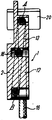
제2도는 제1도의 선 II-II의 단면도.2 is a sectional view taken along the line II-II of FIG.
제3도는 제1도의 화살표 III방향에서 본 저면도.3 is a bottom view from arrow III in FIG.
제4도는 다른 작동 방식을 도시하는, 제1도 실시예의 개략 측면도.4 is a schematic side view of the FIG. 1 embodiment showing another mode of operation.
5도는 본 발명 장치의 사용상태를 도시하는 도식도.5 is a schematic diagram showing a state of use of the apparatus of the present invention.
* 도면의 주요 부분에 대한 부호의 설명* Explanation of symbols for the main parts of the drawings
1 : 하우징 2 : 베이스판1
4 : 덮개 5 : 노브4 cover 5 knob
12 : 마찰 실린더 13 : 마찰 몸체12: friction cylinder 13: friction body
19 : 제어레버19: control lever
본 발명은 로프를 이용하여 사람 또는 하물을 내리기 위한 하물 하강장치에 관한 것으로, 특히 베이스판에 설치한 마찰 실린더와, 보조 마찰 몸체와, 피벗장착된 제어레버를 구비하여, 로프를 이동시 마찰실린더와 마찰몸체의 둘레부분의 적어도 일부를 거치게끔 하고, 로프가 미끄럼 이동할 시 제어레버의 캠면과 마찰식 결합을 이루어 제어레버를 피벗 시킴으로써 자동적으로 제동을 이루게 할 수 있는 하물하강 장치에 관한 것이다.The present invention relates to a load lowering device for lowering a person or a load using a rope, and in particular, a friction cylinder installed on a base plate, an auxiliary friction body, and a control lever mounted with a pivot, and a friction cylinder when the rope is moved. The present invention relates to a load lowering device capable of passing through at least a portion of the circumference of the friction body and automatically braking by pivoting the control lever by frictionally engaging the cam surface of the control lever when the rope slides.
로프를 이용하여 사람을 내리게 하는 장치는 일예로 미합중국 틀허출원 제296,374호에서 찾아볼 수 있는데, 상기 출원의 도면 제7도 내지 제10도에 도시된 바와같은 실시예에 있어서는 로프를 마찰 실린더 둘레에 11/2바퀴 만큼 돌린후 보조 마찰 몸체를 거치게끔 하고, 그뒤에 다시 약 180로 방향을 틀어 피벗식 캠 제어레버를 거치게 한후 보조 마찰 몸체의 평평한 제동면을 거치게하고, 스프링 힘을 받고 있는 상기 제어레버에 의해 로프를 가압하도록 하여, 로프가 제동면과 제어레버 사이를 미끄럼 이동하는 중에 로프를 항상 제어레버와 소정의 마찰을 이루게 하고 있다. 로프는 제어레버를 피벗시키려는 경향을 가지어, 제어레버가 로프를 제동면과의 사이에 쐐기식으로 고정시키게 함으로써, 하강장치를 로프상에 고정시키게 하며, 또한 제어레버는 자유롭게 이동할 수 있어 제동을 해제시켜 로프를 미끄럼 이동시킬 수 있게 되어 있다.A device for lowering a person using a rope can be found, for example, in U.S. Patent Application Nos. 296,374. In the embodiment as shown in FIGS. 7 to 10 of the application, the rope is wrapped around a friction cylinder. After turning 11/2 wheels, the sub frictional body is subjected to the rotation, and then rotates about 180 degrees to the pivot cam control lever, and then through the flat braking surface of the sub frictional body, and the control under the spring force. The lever is pressed by the lever so that the rope is always in friction with the control lever while the rope is sliding between the braking surface and the control lever. The rope has a tendency to pivot the control lever, causing the control lever to wedge securely between the braking surface, thereby securing the lowering device on the rope, and the control lever can move freely to provide braking. It can be released to slide the rope.
상기 장치의 주된 단점은 장치의 기능을 발휘하는데 스프링을 사용한다는데 있는 것으로, 그 이유는 상기 스프링이 스프링 자체의 손상의 위험 또는 오랜기간 사용치 않은 후에 사용할때 다른 요인에 의해 발생할 수도 있는 작동불능의 위험을 방지할 수 있도록 주기적으로 기능시험을 하여야 하는 취약부이고, 또한 장치의 작동 성능이 스프링의 적절한 기능 발휘시에만 제대로 발휘되기 때문이다.The main disadvantage of the device is the use of springs to function the device, because of the risk of damage of the spring itself or of inoperability which may be caused by other factors when used after long periods of inactivity. This is because it is a weak point that must be regularly tested to prevent danger, and the operating performance of the device is only properly performed when the spring is properly functioned.
상기 출원의 도면 제1도 내지 제7도의 실시예에 있어서는 로프가 감긴 보조마찰몸체를 이심적으로 피벗시키게 하여 로프의 회전 이동시 보조 마찰몸체가 피벗되면서 로프를 제동면과 함께 사이에 쐐기식으로 고정시켜 더 이상의 로프의 이동을 방지시키게 하기 때문에 상술한 바와 같은 단점은 없게 된다. 그러나 이러한 구성의 장치는 복잡하고 비용도 많이 들 뿐만 아니라, 하강이 요구되는 경우 보조 마찰 몸체의 제동력에 대해 반발하도록 제어레버로 부터 기어를 통해 보조마찰 몸체에 힘이 전달되어야 하기 때문에, 거친 환경에 사용하는 경우 파괴될 위험도 있고, 상기한 바와같은 기어가 더럽혀 지게 되면 기능을 발휘하지 못할 뿐만 아니라, 공차가 적게 정밀 가공된 부품들도 다수 필요하게 된다.In the embodiments of FIGS. 1 to 7 of the application, the auxiliary friction body wound around the rope is pivotally pivoted so that the auxiliary friction body pivots in a wedge fashion between the braking surface and the pivoting body during the rotational movement of the rope. This prevents further movement of the rope so that there are no disadvantages as described above. However, the device of this configuration is not only complicated and expensive, but also requires a force to be transmitted to the auxiliary friction body through the gear from the control lever to counteract the braking force of the auxiliary friction body when lowering is required. In use, there is a risk of being destroyed, and if the gears are dirty as described above, they will not function but also require a large number of precision machined parts with low tolerances.
로프를 이용하여 사람 또는 하물을 내리게 하는 공지의 하물 하강장치는 그다지 단순하게 되어 있지 않고 있으며, 또한 작동 안전성을 위한 다음의 요건을 충족시키지 못하고 있다.Known load lowering devices which use ropes to unload people or loads are not very simple and do not meet the following requirements for operational safety.
가) 장치는 다양한 직경의 로프에 대해 사용 가능하여야 한다. 즉, 로프가 물을 흡수함으로 인해 직경 증가를 이룸으로써 발생하게 되는 직경 변화에 대해 적응할 수 있어야만 한다.A) The apparatus is to be available for ropes of various diameters. That is, the rope must be able to adapt to the change in diameter caused by the increase in diameter due to the absorption of water.
나) 스프링 및 기어휘일과 같이 파손괴기 쉬운 기계부품들이 사용되지 말아야만 한다.B) Mechanical parts prone to breakage, such as springs and gear wheels, shall not be used.
다) 장치를 상기(가)의 요건에서 언급한 것 보다 더욱 큰 직경차를 갖는 다양한 직경의 로프에 대해 사용가능하게 할 수 있도록, 제동에 필요한 이심 장착부를 갖는 제어레버는 용이하게 교환가능하여야만 한다.C) Control levers with eccentric mountings required for braking should be easily interchangeable in order to enable the device to be used for ropes of various diameters having a larger diameter difference than those mentioned in (a) above. .
라) 속도제어가 정확해야만 한다.D) Speed control must be accurate.
마) 로프가 요구되는 방향이 아닌 다른 방향으로 제어레버를 거쳐 이동할때와 같이 정확치 못하게 장치내에 삽입되었을 경우에도 제동은 이루어져야만 한다.E) Braking shall be carried out even if the rope is inserted in the system incorrectly, such as when moving through the control lever in a direction other than the required direction.
바) 조작자가 장치를 부정확하게 조각하였을 경우에도(즉, 조작자가 제동을 위해 제어레버를 밀거나 당기는 경우 모두) 제동을 이루어져야만 한다.F) Braking shall be performed even if the operator has carved the equipment incorrectly (ie, if the operator pushes or pulls the control lever for braking).
사) 장치는 로프를 따라 하강하고 또한 제위치에 고정될 수 있도록 여러방식으로 작동될 수 있어야만 한다.G) The device must be capable of operating in several ways so that it can be lowered along the rope and held in place.
따라서, 본 발명의 목적은 상술한 바와같은 요건을 충족시킬 수 있는 로프를 이용하는 하물 하강장치를 제공하는 것으로, 상기한 요건은 보다 큰 작동안정성 및 단순화를 위해 꼭 필요한 것이다. 상기한 목적은 본 발명에 따라, 보조 마찰 몸체상에서의 로프의 이동방향으로 연장되는 오목한 제동면을 제공하고, 상기 오목한 제동면의 반대쪽에 위치하는 제어레버의 단부에 두 개의 캠면을 제공함으로써 달성될 수 있다.It is therefore an object of the present invention to provide a load lowering device using a rope capable of meeting the above requirements, which is necessary for greater operational stability and simplicity. The above object is achieved according to the invention by providing a concave braking surface extending in the direction of movement of the rope on the auxiliary friction body and providing two cam faces at the ends of the control lever located opposite the concave braking surface. Can be.
이와같이 구성함으로써, 레버가 요구되는 방향이 아닌 다른 방향으로 우연히 밀리거나 당겨지는 경우에도 제동은 이루어질 수 있게되며, 또한 로프가 제어레버의 캠면을 따라 어느 방향으로 미끄러지던지 간에 자기 제동이 이루어지기 때문에 로프의 형상이 다양하도라도 제동은 이루어질 수 있게 되며, 또한 캠면을 갖는 제어레버는 단순하게 형성되어 있고 장착도 용이하기 때문에 용이하게 교환가능하게 되어 있다. 따라서, 직경이 아주 다른 로프를 사용하여야 하는 경우에는 제어레버를 교환하면 된다. 그러나, 그와같이 제어레버를 교환하지 않아도 본 발명의 장치는 다소의 직경변화를 갖는 로프에 대해 사용할 수 있게 되는데, 그 이유는 로프가 제어레버의 캠면에 항상 맞물리어 쐐기식의 자기 제동을 이룰 수 있게끔 마찰 몸체의 오목한 면을 따라 신장되기 때문이다.With this configuration, braking can be achieved even if the lever is accidentally pushed or pulled in a direction other than the required direction, and also because the rope is self-braking in which direction the rope slides along the cam surface of the control lever. The braking can be made even if the shape of the manifold is varied, and the control lever having the cam surface is easily exchanged since it is simply formed and easy to mount. Therefore, if a rope with a very different diameter must be used, the control lever can be replaced. However, without changing the control lever, the device of the present invention can be used for a rope having a slight change in diameter because the rope always engages the cam surface of the control lever to achieve wedge magnetic braking. This is because it extends along the concave side of the friction body.
도면, 특히 제1도에는 로프를 사용하여 하물 또는 사람을 내리기 위한 하물 하강장치가 도시되어 있는데, 상기 장치는 베이스판(2)과, 연부(3)로된 하우징을 가지고 있으며, 상기 하우징에는 덮개(4)가 힌지되어 있다. 제1도에 있어서, 상기 덮개(4)는 열려져 있어 하우징의 내부가 보여지고 있으며, 우측으로 피벗시 닫혀지게 되는데, 그때, 나사노브(5)를 돌려 나사구멍(6)에 결합시킴으로써, 덮개(4)를 닫힌 상태로 고정시킬 수 있게 된다.The drawing, in particular FIG. 1, shows a load lowering device for lowering a load or a person using a rope, the device having a
베이스판(2)의 상부 및 하부에는 각각 제1개구(7) 및 제2개부(8)이 형성되어 있는데, 상기 개구들은 후술하는 바와같이 조작자가 로프를 타고 미끄럼 하강하게 되는 방식에 따라 선택적으로 사용되게 된다. 또한 연부(3)에는 제1개구(9), 제2개구(10), 그리고 제3개구(11)가 형성되어 있다.A
하우징의 내부에는 고정된 마찰실린더(12)가 위치되며, 상기 마찰실린더(12)의 상부에는 보조 마찰몸체(13)가 고정되어 있는데, 그 보조 마찰몸체(13)는 표면이 거칠게 형성되어 있고 그의 하부에는 볼록면(14)이 형성되어 있고, 상부에는 오목한 제동면(15)이 보조 마찰몸체(13)의 축부를 따라 형성되어 있다.A fixed
상기 보조 마찰몸체(13)의 제동면(15)의 반대측에는 손잡이(20)를 사용하여 수동 조작할 수 있는 제어레버(19)가 위치되어 있는데, 상기 제어레버(19)는 피벗 베어링(21)에 피벗식으로 장착되고, 제동면(15)쪽으로 면해 있는 제어레버 단부에는 두 개의 캠면(22),(23)이 형성되어 있다.On the opposite side of the
상기 캡면(22),(23)은 피벗 베어링(21)의 회전축과 각 캡면(22),(23)간의 거리가 레버(19)의 단부상의 이웃하는 다른 표면과 상기 피벗 베어링의 회전축간의 거리보다 클 수 있게끔 형성되어 있다. 또한 캡면(22),(23)의 형태는 제어레버(19)가 요구되는 대로 상측, 또는 하측으로 피벗이동될때 각 캡면(22),(23)이 제동면(15)과의 거리를 감소시킬수 있도록 상기 제동면(15)쪽으로 이동할 수 있게끔 되어 있으며, 대체로 피벗 베어링(21)의 양측에 위치하게 된다. 제어레버(19) 다른표면은 캡면(22),(23)사이에 위치하여야 하고, 피벗 베어링(21)의 축으로부터 상기 다른 표면까지의 거리는 피벗베어링(21)의 축과 각 캡면(22),(23)간의 거리보다 작아야 한다.The cap faces 22, 23 are the distances between the axis of rotation of the pivot bearing 21 and each
제1도에 있어서, 로프(16)는 하강이동을 이루게 할 수 있게끔 하우징내에 위치되어 있다. 즉 제5도에 도시된 바와 같이 로프의 상단은 고정점에 부착되어 있다. 로프를 이용하여 하강하기 위해서는 먼저 조작자는 트리거스냅에 의해 베이스판(2)의 하우징개구(8)에 후크식으로 연결된 벨트(17)에 매어지도록 해야 한다. 그리고 로프(16)를 아래로부터 개구 (11)를 통해 하우징(1)내로 삽입시켜야 하며, 그뒤에는 로프(16)를 마찰몸체(13)의 둘레에 감아돌린 후, 제동면(15)을 거치게 하고, 다시 그로부터 방향을 약 180°로 틀어 볼록면(14)을 거치게 하고, 그뒤에는 원통형 마찰실린더(12)의 둘레에 약 270°의 호형태로 감아돌린 후 상측으로 이동시켜 개구(9)를 통해 하우징(1)으로 부터 빠져나오게 한다.In FIG. 1, the
로프는 두 개의 평면을 따라 이동하게 되는데, 제2도에 도시된 바와같이, 베이스판(2)의 벽은 로프의 경로를, 로프가 마찰몸체(13)의 둘레를 따라 방향을 전환하게 되는 상측위치(A)와, 로프가 마찰실린더(13)의 하측 둘레를 거치게 되는 하측위치(B)간을 제1도의 평면에 대해 수직하는 방향으로 로프직경과 대체로 동일한 양만큼 측방향으로 변위시킬 수 있게끔 경사져 있다.The rope moves along two planes. As shown in FIG. 2, the wall of the
제1도 및 5도의 배치상태에서, 레버(19)는 두 개의 작동위치간을 이동할 수 있게 되는데, 레버의 제1작동위치에서 로프에 매달린 조작자는 하강할 수 있게된다. 조작자는 장치의 개구(8)에 연결된 벨트(17) 및 트리거 스냅(18)에 의해 장치에 매달리게 되어 있어, 조작자의 자중에 의해 장치를 하측으로 잡아 내리게 되며, 그 결과 로프(16)은 개구(9)를 통해 상측으로 잡아당겨지게 된다. 또한 로프는 하측으로 부터 개구(11)을 통해 상측으로 이동하여, 먼저 마찰몸체(13)의 제동면(15)과 캡면(22)사이를 통과하게 되는데, 이때 로프는 캡면(22)과 마찰접촉을 하며 캡면(22)을 제1도에 도시된바와 같이 시계방향으로 피벗시킴으로써 캡면(22)과 제동면(15)간의 거리를 감소시키게 된다. 그리하여, 제어레버(19)는 제1도에 도시된 위치로 피벗되게되고, 그에 따라 로프(16)는 캡면(22)과 제동면(15)사이에 쐐기식으로 단단하게 고정되게되며, 이와같이 됨으로써 제어레버(19)를 조작할 필요없이도 장치를 로프상에 위치고정시킬 수 있게 된다.In the arrangement of FIGS. 1 and 5, the
제2작동위치에서, 로프에 매달린 조작자가 제어레버(19)를 점선"ㄴ"과 대체로 평행한 위치까지 피벗시키면, 마찰몸체(13)의 제동면(15)과 제어레버(19)의 표면사이의 거리는 로프를 쐐기식으로 고정되게 함이 없이 마찰몸체와 제어레버 사이로 통과시킬 수 있게끔 되어, 로프는 위치(A)까지 상측으로 이동될 수 있게되고, 그 위치에서 방향을 전환하여 마찰몸체(13)의 볼록면(14)을 거쳐가게되며, 그 뒤에는 마찰실린더(12)의 둘레상을 270°만큼 돌아간 후에 상측으로 이동하여 개구(9)를 통해 하우징(1)으로 부터 빠져나가게 된다. 로프는 마찰몸체(13) 및 마찰실린더(12)를 돌아 이동하게 되어 부분적으로 제동되게 된다.In the second operating position, when the operator suspended from the rope pivots the
캡면(22)와 제동면(15)은 제어레버(19)가 위치(ㄴ)에 있을때 로프가 장치를 통해 요구되는 초기속도로 이동할 수 있게할 수 있게끔 조작자의 중량이 충분히 크게 될 수 있도록 조작자의 예상중량을 고려하여 적절한 형태를 가져야하며 서로 짝을 이루어야만 한다. 캡면(22)과 제동면(15)은 제어레버(19)가 위치(ㄴ)에 있을때 로프를 장치를 통해 빠르지 않으면서도 조용하게 그리고 안정되게 이동시킬 수 있도록, 그리고 제어레버가 정ㅊ밀한 속도조절을 위해 반시계방향으로 회전될 수 있게끔 충분히 느슨한 여유를 가질 수 있도록 충분한 제동이 발생되어야만 한다.The
제4도에는 본 발명의 다른 실시예가 도시되어 있는데, 그에 있어서, 로프는 장치를 개구에서 트리거 스냅(25)에 의해 소정의 고정점에 고정시킬 수 있게 하도록 삽입되게 된다.Another embodiment of the present invention is shown in FIG. 4, in which a rope is inserted to enable the device to be secured to a predetermined anchor point by a
제4도에 있어서, 로프(16)는 상측 및 하측 모두로 부터 장치내로 삽입되게되며, 하측을 통해 장치로 부터 빠져나오게 된다. 제4도의 실시예에 있어서, 로프는 양방향으로 모두 이동할 수 있는데, 일예로 로프를 개구(10)를 통해 하측으로 부터 삽입한 후 마찰실린더(12)의 둘레에 1 1/2바퀴맡큼 돌려진 후 마찰몸체(13)의 볼록면(14)과 제동면(15)을 차례로 거치고, 그 뒤에는 다시 개구(11)를 통해 하측으로 이동하여 장치로 부터 빠져나오게 한다. 이와같이 함으로써, 로프는 제어레버(19)의 캡면(22)과 마찰 접촉을 하게되어, 상기 레버(19)를 제4도의 반시계방향으로 피벗시키게 되고, 그에 따라 마찰몸체(13)의 제동면(15)과 캡면(22)간의 거리가 감소하게 됨으로써, 로프는 그 사이에 웨지식으로 조여지게 된다.In FIG. 4, the
제동면과 마주보는 두 개의 캡면(22),(23)을 가진 제어레버(19)의 이동에 따라 장치내로의 로프의 삽입을 각기 다른 방식으로 이루게 할 수 있게되며, 어느 경우에나 또는 어느 방향으로의 이동시에도, 로프는 두 캠면중 하나에 의해 웨지시으로 조여지게 됨으로써 자동적으로 제동되게 되며, 수동조작에 의해 제어레버를 위치(ㄴ)로 피벗시킴으로써 다시 장치를 통해 이동될 수 있게된다.The movement of the
본 발명의 장치는 다양한 직경의 로프에 대해 사용할 수 있는데, 그 이유는 마찰몸체(13)가 제동면(15)과 마주보는 오목형의 캡면(22),(23)을 가지어, 로프가 항상 상기 지역에서 신장되게 되므로써, 로프가 두 캡면(22),(23)중 하나에 대해 가압되게 되고 그에 따라 레버(19)를 마찰을 통해 피벗시켜 제위치에 쐐기식으로 조여지게 됨으로써 자동적으로 제동될 수 있게 되기 때문이다.The device of the present invention can be used for ropes of various diameters, since the
Claims (6)
Applications Claiming Priority (2)
| Application Number | Priority Date | Filing Date | Title |
|---|---|---|---|
| DEP3243952.0 | 1982-11-27 | ||
| DE3243952A DE3243952C2 (en) | 1982-11-27 | 1982-11-27 | Descender |
Publications (2)
| Publication Number | Publication Date |
|---|---|
| KR840007075A KR840007075A (en) | 1984-12-05 |
| KR890000136B1 true KR890000136B1 (en) | 1989-03-08 |
Family
ID=6179217
Family Applications (1)
| Application Number | Title | Priority Date | Filing Date |
|---|---|---|---|
| KR1019830005611A KR890000136B1 (en) | 1982-11-27 | 1983-11-28 | Device for lowering a person or a load on a rope |
Country Status (10)
| Country | Link |
|---|---|
| US (1) | US4580658A (en) |
| EP (1) | EP0110078B1 (en) |
| JP (1) | JPS59108567A (en) |
| KR (1) | KR890000136B1 (en) |
| AT (1) | ATE43069T1 (en) |
| CA (1) | CA1219244A (en) |
| DE (2) | DE3243952C2 (en) |
| IL (1) | IL70263A (en) |
| SG (1) | SG67389G (en) |
| ZA (1) | ZA838257B (en) |
Cited By (1)
| Publication number | Priority date | Publication date | Assignee | Title |
|---|---|---|---|---|
| KR200450338Y1 (en) * | 2008-03-07 | 2010-09-24 | 양해완 | Emergency escape device for high-storied building |
Families Citing this family (42)
| Publication number | Priority date | Publication date | Assignee | Title |
|---|---|---|---|---|
| US5029669A (en) * | 1984-11-30 | 1991-07-09 | Lew Hyon S | Rope climbing and sliding device |
| DE3531391A1 (en) * | 1985-09-03 | 1987-03-12 | Bornack Herbert Fa | Fall brake |
| US4714137A (en) * | 1986-04-29 | 1987-12-22 | Chou Hung Chang | Building safety rescue device |
| DE8709183U1 (en) * | 1986-12-27 | 1987-09-03 | Zenhaeusern, Heinrich, Urdorf, Zuerich, Ch | |
| JPS63255073A (en) * | 1987-04-10 | 1988-10-21 | 石岡 繁雄 | Falling device for refuge |
| US4787474A (en) * | 1987-11-23 | 1988-11-29 | Brennan Daniel F | Rope controller |
| US4881622A (en) * | 1988-03-01 | 1989-11-21 | Henry Machal | Safety grab protection device |
| US4934484A (en) * | 1989-08-07 | 1990-06-19 | Green Kenneth E | Descending life saving device |
| US5348116A (en) * | 1992-08-12 | 1994-09-20 | Pickering Gregory R | Rescue system |
| US5348117A (en) * | 1992-08-12 | 1994-09-20 | Pickering Gregory R | Rescue system |
| US5597052A (en) * | 1995-08-15 | 1997-01-28 | Rogleja; Boris | Descender |
| FR2741539B1 (en) * | 1995-11-28 | 1998-01-30 | Zedel | SELF-LOCKING DESCENDER FOR CONTROL LEVER ROPE |
| US5924522A (en) * | 1997-05-16 | 1999-07-20 | Ostrobrod; Meyer | Cable grab |
| DE10011753C2 (en) * | 2000-03-13 | 2003-10-09 | Hubert Kowalewski | Climbing device for ascending and descending processes |
| US6488267B1 (en) | 2000-09-12 | 2002-12-03 | The United States Of America As Represented By The Secretary Of The Army | Apparatus for lifting or pulling a load |
| FR2815874B1 (en) * | 2000-11-02 | 2002-12-27 | Protecta Internat Sa | PERSONAL SECURITY DEVICE FOR A VERTICAL CABLE |
| US6561313B2 (en) * | 2001-08-16 | 2003-05-13 | Trimorphics, Inc. | Belay/rappel device for use in climbing activities and the like |
| GB2384182A (en) * | 2002-01-17 | 2003-07-23 | Ian Campbell Lyle | Emergency escape apparatus |
| NO318353B1 (en) * | 2002-08-30 | 2005-03-07 | Nordisk Terapi As | Device by training apparatus consisting of a rope which is transported via a hinged steering |
| US6832668B2 (en) * | 2002-12-20 | 2004-12-21 | American Escape Systems, Inc. | Descender apparatus |
| US6820721B1 (en) * | 2002-12-23 | 2004-11-23 | American Escape Systems, Inc. | Rescue apparatus |
| US6814185B1 (en) * | 2003-05-15 | 2004-11-09 | Meyer Ostrobrod | Descent controller with safety brake |
| US9016431B2 (en) * | 2005-06-03 | 2015-04-28 | Great Trango Holdings, Inc. | Load balancing descending device |
| AT502056A1 (en) * | 2005-06-22 | 2007-01-15 | Oebb Infrastruktur Betr Ag | DEVICE FOR SAVING, BORING AND ABORING PERSONS AND / OR GOODS |
| TWM279354U (en) * | 2005-07-05 | 2005-11-01 | Hung-Huei Chen | Suspension type escape device |
| US20070193824A1 (en) * | 2006-02-16 | 2007-08-23 | Anderson Patrick K | Ladder safety apparatus |
| WO2009023833A2 (en) * | 2007-08-15 | 2009-02-19 | Rit Rescue And Escape Systems | Descending device and method of use |
| US20090120720A1 (en) * | 2007-11-13 | 2009-05-14 | Johnny Wayne Arms | Frictionless descender for abseiling along a rope |
| SE533775C2 (en) * | 2009-05-13 | 2011-01-11 | Initium System Ab | Downhill device comprising a suspension rocker with formed braking means |
| DE102009034158B4 (en) * | 2009-07-20 | 2023-11-16 | Flender Gmbh | Encapsulation of an electrical machine |
| US9587434B2 (en) * | 2009-08-21 | 2017-03-07 | Rory Frick | Ladder |
| US8348016B2 (en) * | 2009-08-26 | 2013-01-08 | Lewis Richard W | Descender with fall arrest and controlled rate of descent |
| US8925680B2 (en) * | 2010-07-14 | 2015-01-06 | Brian Christopher Herrli | Rappelling apparatus and method |
| CN102125732B (en) * | 2011-04-14 | 2012-07-18 | 鞍山拜尔自控有限公司 | Climbing type firefighting refuge compartment |
| CN102423513A (en) * | 2011-11-02 | 2012-04-25 | 张一扬 | Controllable high-building escape device |
| US9173386B2 (en) * | 2012-08-13 | 2015-11-03 | Rupp Marine, Inc. | Outrigger line lock positioning device |
| EP3047090B1 (en) | 2013-09-18 | 2018-11-21 | Wing Enterprises, Inc. | Ladders including rope and pulley system and fall protection |
| US9630034B2 (en) * | 2014-02-05 | 2017-04-25 | AHS Rescue, LLC | Method and apparatus for controlled emergency descent |
| US10315056B2 (en) | 2016-07-11 | 2019-06-11 | Great Trango Holdings, Inc. | Belay device |
| US10704623B2 (en) * | 2017-02-14 | 2020-07-07 | Cory Robert Mahana | Rope arrest-and-release device for use on utility poles |
| US20190338593A1 (en) * | 2017-07-17 | 2019-11-07 | Safeworks, Llc | Integrated climb assist and fall arrest systems and methods |
| DE202020102347U1 (en) * | 2019-05-01 | 2020-07-24 | Ti-An Chih | A device that enables immediate and precise locking and loosening of a rope |
Family Cites Families (11)
| Publication number | Priority date | Publication date | Assignee | Title |
|---|---|---|---|---|
| US209137A (en) * | 1878-10-22 | Improvement in fire-escapes | ||
| DE244762C (en) * | ||||
| US394109A (en) * | 1888-12-04 | Fire-escape | ||
| US544724A (en) * | 1895-08-20 | Fire-escape | ||
| GB631984A (en) * | 1943-02-17 | 1949-11-14 | Edward Thomas Wiley | Improvements in portable fire escapes |
| JPS5519611A (en) * | 1978-07-21 | 1980-02-12 | Nissan Motor Co Ltd | Load controller for car |
| FR2448910A1 (en) * | 1979-02-13 | 1980-09-12 | Dressler Bruno | Self locking rope abseiling brake - consists of two rounded pieces over which the rope passes in S=shape |
| FR2451752A1 (en) * | 1979-03-23 | 1980-10-17 | Petzl Paul | IMPROVED SELF-LOCKING DESCENDER |
| FR2472395A1 (en) * | 1979-12-26 | 1981-07-03 | Derrien Le Faucheur Yves | Rope fire escape device for building - has rope passing over pulley in housing with articulated lever attached to pulley for braking and halting downwards movement |
| DE3047284A1 (en) * | 1980-12-16 | 1982-07-15 | Otto 8112 Bad Kohlgrub Brda | Self controlled abseil cable mechanism - has harness secured to friction brake with lever operated locking pulley adjacent to cable loop |
| EP0046891A3 (en) * | 1980-08-30 | 1982-03-17 | Walter Brda | Rope lowering device |
-
1982
- 1982-11-27 DE DE3243952A patent/DE3243952C2/en not_active Expired
-
1983
- 1983-10-13 EP EP83110211A patent/EP0110078B1/en not_active Expired
- 1983-10-13 AT AT83110211T patent/ATE43069T1/en not_active IP Right Cessation
- 1983-10-13 DE DE8383110211T patent/DE3379864D1/en not_active Expired
- 1983-11-07 ZA ZA838257A patent/ZA838257B/en unknown
- 1983-11-08 CA CA000440632A patent/CA1219244A/en not_active Expired
- 1983-11-17 IL IL70263A patent/IL70263A/en not_active IP Right Cessation
- 1983-11-22 US US06/554,257 patent/US4580658A/en not_active Expired - Lifetime
- 1983-11-28 JP JP58224012A patent/JPS59108567A/en active Granted
- 1983-11-28 KR KR1019830005611A patent/KR890000136B1/en not_active IP Right Cessation
-
1989
- 1989-09-30 SG SG67389A patent/SG67389G/en unknown
Cited By (1)
| Publication number | Priority date | Publication date | Assignee | Title |
|---|---|---|---|---|
| KR200450338Y1 (en) * | 2008-03-07 | 2010-09-24 | 양해완 | Emergency escape device for high-storied building |
Also Published As
| Publication number | Publication date |
|---|---|
| EP0110078A3 (en) | 1985-05-15 |
| US4580658A (en) | 1986-04-08 |
| SG67389G (en) | 1990-01-26 |
| JPH0526512B2 (en) | 1993-04-16 |
| IL70263A0 (en) | 1984-02-29 |
| DE3243952A1 (en) | 1984-05-30 |
| IL70263A (en) | 1988-08-31 |
| EP0110078B1 (en) | 1989-05-17 |
| EP0110078A2 (en) | 1984-06-13 |
| ZA838257B (en) | 1984-06-27 |
| CA1219244A (en) | 1987-03-17 |
| JPS59108567A (en) | 1984-06-23 |
| ATE43069T1 (en) | 1989-06-15 |
| DE3379864D1 (en) | 1989-06-22 |
| DE3243952C2 (en) | 1984-11-29 |
| KR840007075A (en) | 1984-12-05 |
Similar Documents
| Publication | Publication Date | Title |
|---|---|---|
| KR890000136B1 (en) | Device for lowering a person or a load on a rope | |
| US5803437A (en) | Chainless drive winch | |
| EP0416079B1 (en) | Self-locking descending device for rope with two locking positions | |
| US3908560A (en) | Counterbalancing system for a drafting table or the like | |
| US3674116A (en) | Fall-prevention safety device | |
| CA2263666A1 (en) | Cable failure device | |
| CA2735381A1 (en) | Fall arrest device | |
| EP0561682A1 (en) | Security apparatus for workers working at high places | |
| EP0018434B1 (en) | Improved up-and-down pulley device for suspension lamps and the like | |
| US5379858A (en) | Compact emergency descender system | |
| US5101937A (en) | Self centering elevator cable safety brake | |
| US3042435A (en) | Self-locking gate latch | |
| EP1460019A1 (en) | Unlocking device for a safety catch of an elevator car, and the safety catch so equipped | |
| EP1948321A2 (en) | Descender | |
| EP1460020A1 (en) | Elevator safety gear | |
| US4437624A (en) | Positioning reel | |
| EP1404605A1 (en) | Device for locking a lift door with independent emergency unlocking | |
| US3113545A (en) | Cleats | |
| GB2367048A (en) | Rope safety device | |
| KR101820631B1 (en) | Floor hinge apparatus | |
| FR2434631A1 (en) | AUTOMATIC SEAT BELT LATCHER | |
| GB2134593A (en) | Door closing devices | |
| GB2131921A (en) | Rope descending device | |
| SU1237068A3 (en) | Apparatus for rope descending of human or load | |
| JP2642276B2 (en) | Belt tension adjustment device for opening and closing shoji |
Legal Events
| Date | Code | Title | Description |
|---|---|---|---|
| A201 | Request for examination | ||
| G160 | Decision to publish patent application | ||
| E701 | Decision to grant or registration of patent right | ||
| GRNT | Written decision to grant | ||
| FPAY | Annual fee payment |
Payment date: 19970308 Year of fee payment: 9 |
|
| LAPS | Lapse due to unpaid annual fee |