KR860002204B1 - Combustion safty device - Google Patents
Combustion safty device Download PDFInfo
- Publication number
- KR860002204B1 KR860002204B1 KR1019830000556A KR830000556A KR860002204B1 KR 860002204 B1 KR860002204 B1 KR 860002204B1 KR 1019830000556 A KR1019830000556 A KR 1019830000556A KR 830000556 A KR830000556 A KR 830000556A KR 860002204 B1 KR860002204 B1 KR 860002204B1
- Authority
- KR
- South Korea
- Prior art keywords
- combustion
- comparator
- burner
- frame current
- main burner
- Prior art date
Links
Images


Classifications
-
- F—MECHANICAL ENGINEERING; LIGHTING; HEATING; WEAPONS; BLASTING
- F23—COMBUSTION APPARATUS; COMBUSTION PROCESSES
- F23N—REGULATING OR CONTROLLING COMBUSTION
- F23N5/00—Systems for controlling combustion
- F23N5/20—Systems for controlling combustion with a time programme acting through electrical means, e.g. using time-delay relays
-
- F—MECHANICAL ENGINEERING; LIGHTING; HEATING; WEAPONS; BLASTING
- F23—COMBUSTION APPARATUS; COMBUSTION PROCESSES
- F23N—REGULATING OR CONTROLLING COMBUSTION
- F23N5/00—Systems for controlling combustion
- F23N5/003—Systems for controlling combustion using detectors sensitive to combustion gas properties
- F23N5/006—Systems for controlling combustion using detectors sensitive to combustion gas properties the detector being sensitive to oxygen
-
- F—MECHANICAL ENGINEERING; LIGHTING; HEATING; WEAPONS; BLASTING
- F23—COMBUSTION APPARATUS; COMBUSTION PROCESSES
- F23N—REGULATING OR CONTROLLING COMBUSTION
- F23N2229/00—Flame sensors
-
- F—MECHANICAL ENGINEERING; LIGHTING; HEATING; WEAPONS; BLASTING
- F23—COMBUSTION APPARATUS; COMBUSTION PROCESSES
- F23N—REGULATING OR CONTROLLING COMBUSTION
- F23N2229/00—Flame sensors
- F23N2229/02—Pilot flame sensors
Landscapes
- Engineering & Computer Science (AREA)
- Chemical & Material Sciences (AREA)
- Combustion & Propulsion (AREA)
- Mechanical Engineering (AREA)
- General Engineering & Computer Science (AREA)
- Control Of Combustion (AREA)
- Regulation And Control Of Combustion (AREA)
Abstract
Description
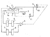
제1도는 이미 제안된 계통선도.1 is a schematic diagram already proposed.
제2도는 본 발명장치의 일예의 계통선도.2 is a system diagram of an example of the apparatus of the present invention.
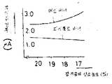
제3도는 공기과잉율에 대한 후레임전류치와 CO/CO2값의 변화를 표시한 선도.3 is a diagram showing the change of the frame current value and the CO / CO 2 value for the excess air ratio.
제4도는 후레임전류치의 변화특성도.4 is a characteristic diagram of change of the frame current value.
제5도는 제1 비교기의 입력전위의 변화특성도.5 is a characteristic diagram of change of the input potential of the first comparator.
제6도는 제2 비교기의 입력전위의 변화특성도.6 is a characteristic diagram of change of the input potential of the second comparator.
* 도면의 주요부분에 대한 부호의 설명* Explanation of symbols for main parts of the drawings
1 : 메인버너 2 : 파이롯드버너1: main burner 2: pilot burner
1a, 2a : 연소면 5 : 후레임롯드1a, 2a: combustion surface 5: frame rod
6 : 제1 비교기 12 : 제 2비교기6: first comparator 12: second comparator
본 발명은 전1차(全1次)공기식 연소장치의 연소안전장치에 관한 것이다.The present invention relates to a combustion safety device of an all-first air combustion device.
본원 출원인은 이미 이런 종류의 장치로서 일본국 특허원 소56-177833호에 의해 제1도에 표시한 바와같이 메인버너(1)와 파이롯드버너(2)를 예를 들면 연소팬(3)에서의 공기를 1차공기로서 연소하는 전1차공기식의 가스버너로 구성하고 각 버너(1)(2)에의 공급공기량을 예를 들면 제어판(4)에 의해 조정하여 파이롯드버너(2)의 공기과잉율(공급공기량/연소필요공기량)을 메인버너(1)의 공기과잉을 보다 작은 값으로 설정함과 동시에 메인버너(1)와 파이롯드버너(2)와의 각 연소면(1a)(2a)에 각각 별개의 후레임롯드(5)(5)를 설치하며 메인버너(1)의 후레임전류치와 파이롯드버너(2)의 후레임전류치를 검출하고 이들 양 후레임전류치를 비교기(6)로 비교하여 산소결핍시의 연소를 정지하고, CO/CO2값의 증가에 의한 일산화탄소 중독사고의 발생을 미연에 방지하도록 한 것을 제안하였다.Applicant has already applied this type of apparatus to the main burner 1 and the
이러한 장치는 전1차공기식 버너의 후레임전류치를 검출하면 후레임전류치는 버너의 인폿트에 따라 그 절대치는 변하지만 공기과잉율에 대한 변화특성은 제3도의 a선으로 표시한 바와 같이 공기과잉을 1.0-1.1의 범위에서 피이크가 되는 산형(山形)의 특성을 나타내는 것에 착안하여 제안된 것으로 이를 더욱 상술하면 메인버너(1)의 파이롯드버너(2)와의 공기과잉율을 예를 들면 전자를 1.5, 후자를 1.1로 설정하면 공기중의 산소농도가 저하되어 실질적인 과잉율이 저하됨에 따라 제4도에 표시한 바와 같이 메인버너(1)의 후레임전류치의 증가와 파이롯트버너(2)의 후레임전류치의 감소가 생기게 되어 이들 양 후레임전류치를 각각 전류-전압변환기(7)(7)와 증폭기(8)(8)를 설치하여 비교기(6)에 입력시켜 비교하면 증폭기(8)(8)의 증폭율을 알맞게 설정하는 것에 의해 예를 들면 공기중 산소농도의 18%으로의 저하로 제5도에 표시한 바와 같이 비교기(6)에의 파이롯드버너(2)측의 입력전위가 메인버너(1)측에서의 입력전위를 밑돌게 되며 이것에 의하면 공기중 산소농도의 18%으로의 저하로 비교기(6)에서 낮은 레벨의 출력이 발생되어서 가스공급로(9)에 설치되는 전자안전변(10)이 닫히게 되어 연소가 정지된다.When such a device detects the frame current value of the primary air burner, the frame current value changes according to the burner's inpot, but the change characteristic of the air excess rate is indicated by a line in FIG. The present invention has been proposed in view of showing the characteristic of a mountain peak that becomes a peak in the range of 1.0-1.1. More specifically, the ratio of excess air to the
또한 도면중(11)은 메인버너(1)에의 가스공급을 공급하거나 차단시키는 온도조절용과 기타의 제어변을 표시한 것이다.In addition, 11 in the figure shows the temperature control and other control valves for supplying or blocking the gas supply to the main burner 1.
여기에서 고무관을 밟은 경우나 공급가스압의 저하등으로 가스공급로(9)내의 가스압이 심상치 않게 저하되면 공급공기량이 변화하지 않는데 공급가스량에 따라서 연소필요 공기량이 저하되고 미리 공기과잉량을 크게 설정한 메인버너(1)의 공기과잉량이 심상치 않게 증가이며 이 경우 CO/CO2값은 제3도의 b선으로 표시한 바와 같이 산소결핍에 의한 공기과잉량의 감소시와 마찬가지로 증가하나 이러한 상태에 있어서 메인버너(1)측의 입력전위는 파이롯드버너(2)측의 입력전위보다 낮고 상기의 장치로는 비교기(6)에 의한 연소의 정지를 할 수 없는 불편이 따른다.Here, if the gas pressure in the gas supply passage 9 decreases unexpectedly when the rubber tube is stepped on or the supply gas pressure decreases, the amount of supply air does not change. The excess air in the main burner 1 is significantly increased, and in this case, the CO / CO 2 value is increased in the same manner as the decrease of the excess air due to oxygen deficiency, as indicated by the b line in FIG. The input potential on the burner 1 side is lower than the input potential on the
본 발명은 이러한 불편을 해소하고 상기에서 제안한 장치의 개량장치를 제공하는 것을 그 목적으로 하는 것으로 이하 본 발명을 첨부도면 제2도에 표시한 실시예에 따라 설명한다.The present invention aims to solve such inconvenience and to provide a device for improving the above-mentioned device. The present invention will now be described according to the embodiment shown in FIG.
제2도에 있어서 상기에서 제안한 것과 동일한 부재에는 제1도와 동일한 부호를 사용하였다.In FIG. 2, the same code | symbol as FIG. 1 was used for the same member proposed above.
본 발명에 있어서는 메인버너(1)의 후레임전류치와 파이롯드버너(1)의 후레임전류치를 비교하는 제1 비교기(6)에 덧붙혀서 메인버너(1)의 후레임전류치를 기준치와 비교하는 제2 비교기(12)를 설치하고 이 제2 비교기(12)에 의해 공기과잉율의 증가로 후레임전류치가 기준치를 밑돌았을때 연소가 정지되도록 하였다.In the present invention, in addition to the first comparator 6 for comparing the frame current value of the main burner 1 and the frame current value of the pilot burner 1, the second comparator for comparing the frame current value of the main burner 1 with the reference value. (12) was installed, and the
이를 더욱 상술하면 제2 비교기(12)에 메인버너(1)측의 증폭기(8)에서의 전위를 입력하고 이 제2 비교기(12)의 기준전위 Vo를 메인버너(1)의 공기과잉율이 예를들면 2.0이상으로 되었을 때의 후레임전류치에 대응하는 값으로 설정하여 가스압 저하에 의한 공기과잉율의 증가로 이것이 2.0이상으로 되어서 CO/CO2값이 증가하는 상태로 되면 제6도에 표시한 바와 같이 제2 비교기(12)의 입력전위가 기준전위 Vo를 밑돌아서 제2 비교기(12)에서 낮은 레벨의 출력이 발생되도록 하였다.More specifically, the potential of the amplifier 8 on the main burner 1 side is input to the
그리고 이 제2 비교기(12)와 상기한 제1 비교기(6)와의 출력을 입력하는 AND회로(13)을 설치하여서 양 비교기(6)(12)중 어느 한쪽의 출력이 낮은 레벨로 되었을 때는 이 AND회로(13)의 출력이 낮은 레벨로 되어서 전자안전변(10)이 닫혀지도록 하여 산소결핍시는 상기한 앞에서 제안한 것과 마찬가지로 제1 비교기(6)에서 낮은 레벨의 출력이 발생되어서 연소가 정지되고 공기과잉율의 이상증가시는 제2 비교기(12)에서 낮은 레벨의 출력이 발생되어서 연소가 정지되도록 하였다.And when the AND circuit 13 which inputs the output of this
이와 같이 본 발명에 의할 때는 제2 비교기를 설치하여서 산소결핍시 뿐만 아니라 가스압 저하에 의한 공기과잉율의 증가에서도 연소가 정지되는 것으로 안전한 효과를 갖는 것이다.As described above, according to the present invention, the second comparator is installed to stop the combustion not only at the time of oxygen deficiency but also at the increase of the excess air ratio due to the decrease in gas pressure, thereby having a safe effect.
Claims (1)
Applications Claiming Priority (2)
| Application Number | Priority Date | Filing Date | Title |
|---|---|---|---|
| JP57-21082 | 1982-02-15 | ||
| JP57021082A JPS58138919A (en) | 1982-02-15 | 1982-02-15 | Combustion safety device in total primary air type combustion equipment |
Publications (2)
| Publication Number | Publication Date |
|---|---|
| KR840003758A KR840003758A (en) | 1984-09-15 |
| KR860002204B1 true KR860002204B1 (en) | 1986-12-31 |
Family
ID=12044956
Family Applications (1)
| Application Number | Title | Priority Date | Filing Date |
|---|---|---|---|
| KR1019830000556A KR860002204B1 (en) | 1982-02-15 | 1983-02-11 | Combustion safty device |
Country Status (2)
| Country | Link |
|---|---|
| JP (1) | JPS58138919A (en) |
| KR (1) | KR860002204B1 (en) |
Families Citing this family (2)
| Publication number | Priority date | Publication date | Assignee | Title |
|---|---|---|---|---|
| JPS6057126A (en) * | 1983-09-09 | 1985-04-02 | Matsushita Electric Ind Co Ltd | Combustion control device |
| JPH11503817A (en) * | 1995-04-19 | 1999-03-30 | ボウィン テクノロジー ピーティーワイ リミテッド | Heating equipment |
-
1982
- 1982-02-15 JP JP57021082A patent/JPS58138919A/en active Granted
-
1983
- 1983-02-11 KR KR1019830000556A patent/KR860002204B1/en not_active IP Right Cessation
Also Published As
| Publication number | Publication date |
|---|---|
| KR840003758A (en) | 1984-09-15 |
| JPS58138919A (en) | 1983-08-18 |
| JPS6326814B2 (en) | 1988-05-31 |
Similar Documents
| Publication | Publication Date | Title |
|---|---|---|
| US3602487A (en) | Blast furnace stove control | |
| EP0068323A3 (en) | System for feedback control of air/fuel ratio in ic engine with means to control current supply to oxygen sensor | |
| KR860002204B1 (en) | Combustion safty device | |
| US4189295A (en) | Control for heating apparatus | |
| US4493635A (en) | Oxygen-enriched air ratio control device for combustion apparatus | |
| JPS55123345A (en) | Exhaust gas reflux apparatus | |
| GB1126812A (en) | A method of and apparatus for controlling the induced flow through a heat exchange unit of gases | |
| JPS6239331B2 (en) | ||
| JPS5955334A (en) | System for controlling injection of reducing agent in denitrator for stack gas | |
| JPS5381824A (en) | Diagnostic device of air fuel ratio controller | |
| KR920008683B1 (en) | System for controlling the atmosphere of the heat treatment furnace | |
| JPH0791539B2 (en) | Air blowing method for coke dry fire extinguishing equipment | |
| JPH11159756A (en) | Water injection control device for oil fired dln combustor | |
| JPS5743120A (en) | Operation of low nox boiler | |
| JPS5824688B2 (en) | Flow rate control method in exhaust gas treatment equipment | |
| JPS61276624A (en) | Method for controlling oxygen-enriched combustion and controlling device thereof | |
| JPS6071027A (en) | Controlling method of ammonia injection amount in dry waste gas denitration apparatus | |
| JPS5952515A (en) | Method for controlling flow rate of ammonia in waste gas denitration apparatus | |
| JPS618517A (en) | Burning safety device | |
| KR870000664B1 (en) | Combustion safty device | |
| JPS5543383A (en) | Imperfect-combustion detector | |
| JPS5582224A (en) | Combustion control method based on concentration of o2 and co in combustion waste gas | |
| JPS60117001A (en) | Control system of combustion of mixed firing boiler | |
| JPS55109952A (en) | Air-fuel-ratio detection circuit using titania type sensor | |
| JPS599281Y2 (en) | Mixed combustion fuel control device |
Legal Events
| Date | Code | Title | Description |
|---|---|---|---|
| A201 | Request for examination | ||
| E902 | Notification of reason for refusal | ||
| G160 | Decision to publish patent application | ||
| E701 | Decision to grant or registration of patent right | ||
| GRNT | Written decision to grant | ||
| FPAY | Annual fee payment |
Payment date: 19891229 Year of fee payment: 4 |
|
| LAPS | Lapse due to unpaid annual fee |