KR860001418B1 - Weft operating apparatus during stopping of jet loom - Google Patents
Weft operating apparatus during stopping of jet loom Download PDFInfo
- Publication number
- KR860001418B1 KR860001418B1 KR1019830003351A KR830003351A KR860001418B1 KR 860001418 B1 KR860001418 B1 KR 860001418B1 KR 1019830003351 A KR1019830003351 A KR 1019830003351A KR 830003351 A KR830003351 A KR 830003351A KR 860001418 B1 KR860001418 B1 KR 860001418B1
- Authority
- KR
- South Korea
- Prior art keywords
- weft
- loom
- woven fabric
- stopping
- jet loom
- Prior art date
Links
Images


Classifications
-
- D—TEXTILES; PAPER
- D03—WEAVING
- D03D—WOVEN FABRICS; METHODS OF WEAVING; LOOMS
- D03D51/00—Driving, starting, or stopping arrangements; Automatic stop motions
Abstract
Description
제1도는 본발명을 실시하는 애어젯트직기의 구동계의 개요를 표시하는 측면도.BRIEF DESCRIPTION OF THE DRAWINGS The side view which shows the outline | summary of the drive system of the jet loom which implements this invention.
제2도는 본발명을 실시하는 장치의 개략평면도.2 is a schematic plan view of an apparatus for carrying out the present invention.
제3(a)도, 제3(b)도는 본발명의 원리를 설명하는 측면도.3 (a) and 3 (b) are side views illustrating the principle of the present invention.
제4(a)도, 제4(b)도, 제4(c)도는 본발명을 실시하는 장치의 측면도.4 (a), 4 (b), and 4 (c) are side views of the apparatus for carrying out the present invention.
제5도는 본발명을 실시하는 다른장치의 측면도이다.5 is a side view of another apparatus for implementing the present invention.
* 도면의 주요부분에 대한 부호의 설명* Explanation of symbols for main parts of the drawings
11 : 구동모우터 15 : 크랭프샤프트11: drive motor 15: crankshaft
24 : 종광틀 25 : 바디24: heald frame 25: body
26 : 위입가이드 43 : 공급로울러26: enclosed guide 43: supply roller
44 : 위사 46 : 풀파이프44: weft 46: full pipe
48 : 그립퍼 50 : 측장드럼48: gripper 50: side drum
49 : 메인 애어 젯트노즐 51, 52 : 검출기49: main air jet nozzle 51, 52: detector
53 : 압출부재 54 : 아암(腕)부재53
61 : 흡인노즐 62 : 왕복운동부재61: suction nozzle 62: reciprocating member
63 : 유도판 64 : 위사절단용 캇터63: guide plate 64: weft cutting cutter
67 : 유체압실린더 74 : 종간67: fluid pressure cylinder 74: longitudinal
91 : 자(子)압출부재 88. 89 : 리미트스윗치91: child extrusion member 88. 89: limit switch
본발명은 무저(無![]()
![]()
제직작업의 고속화를 도모하기 위하여 측장(測長)한 위사를 젯트노즐로부터 상하경사 사이에 형성된 저구(![]()
![]()
이와같은 고속직기에서는 제직속도가 크므로 직기의 정지에 의하여 생기는 생산성 저하에 대한 영향이 종래의 직기보다 현저하다.In such a high speed loom, the weaving speed is large, and thus the effect on productivity decrease caused by the stopping of the loom is more pronounced than in the conventional loom.
따라서 젯트직기에서는 직기정지시간을 가급적 짧아지게 하는 것이 바람직하다.Therefore, it is desirable for the jet loom to keep the loom stop time as short as possible.
한편, 젯트직기에 있어서는 종래의 유저직기와 달라 북을 사용하지 않고 위사를 공기 또는 물과 같은 유체에 의하여 저구속을 비주(飛走)시키고 있으므로 유저직기에 비하여 위입미스(miss)가 생기기 쉽다.On the other hand, in jet looms, unlike the conventional user looms, the weft yarns are low-restrained by a fluid such as air or water, without using a book.
즉, 젯트노즐로부터 위사가 공급되지 않는 소위 위입공급미스가 생기거나 젯트노즐로부터 공급은 되었으나 젯트노즐의 반대쪽의 이사(耳![]()
![]()
또 고속도로 작동하고 있는 젯트직기에서는 위입미스를 발견한 직후에 직기의 구동을 정지시켜도 직기의 각 부분이 과대한 감속도에 의하여 파괴되는 것을 방지하기 위하여 위입미스검출후 약 1사이클정도 관성작동시킨 후에 직기가 정지하도록 타임밍선정되고 있다.In the jet loom operating on the highway, even if the loom is stopped immediately after finding the inlet miss, each part of the loom is inertial operation after detection of the inlet miss for about one cycle in order to prevent each part of the loom from being destroyed by excessive deceleration. The time is selected to stop the loom.
이때문에 종래 위입미스신호에 의하여 젯트직기가 정지한 경우에는 정지하기 전에 그 다음의 위입사이클이 수행되어 버린다.For this reason, when the jet loom is stopped by the conventional slipping miss signal, the next stepping cycle is performed before stopping.
따라서 기대(機台)를 역전시켜서 그 위입미스가 발생된 위사뿐만 아니라 그 위입미스후의 사이클에 있어 위입된 위사도 제거시켜야 할 필요가 있다.Therefore, it is necessary to reverse the expectation to remove not only the weft yarns in which the false entry occurred but also the weft yarns in the cycle after the false miss.
그런데 위입미스 직후에 위입된 위사는 통상의 위사와 마찬가지로 비이팅(筬打)된 직포에 단단하게 보지되어 있으므로 쉽게 제거되지 않아 그 제거작업이 극히 번거로와진다.By the way, the weft yarn enclosed immediately after the weft miss is held firmly in the woven fabric like the normal weft yarn, so it is not easily removed and the removal work is extremely cumbersome.
또 직성작업중에 경사(耳![]()
![]()
본출원인은 상술한 바와 같이 젯트직기가 이상 정지할때등의 위입미스된 위사를 제거를 자동적으로 행할 수 있는 방법으로서 정지 신호에 의하여 젯트직기를 개구상태로 정지시켜 정지직전에 위입된 위사를 자유로운 상태가 되게 하고 압축개시 신호에 따라 젯트직기에 설치된 압출부재를 전기한 위사와 직포와의 사이에 자동적으로 삽입시켜서 이 위사를 직포로부터 분리시키고 분리된 위사를 제거시키는 젯트직기의 정지시의 위사처리방법을 제안하였다.As described above, the present applicant can automatically remove the missed weft yarns such as when the jet loom stops abnormally, and stop the jet loom in the opening state by the stop signal to free the weft yarns just before stopping. Weft treatment at the time of stopping of the jet loom which separates the weft from the woven fabric by automatically inserting the extrusion member installed on the jet loom between the electric weft and the woven fabric according to the compression start signal. A method was proposed.
이 제안방법에 의하여, 예를들면 위입미스후의 사이클 즉 직기정지직후의 사이클에서 위입된 위사를 먼저 제거한다. 이어서 그 사이클전에 위입되어 위입미스를 발생한 위사를 마찬가지로 이 제안방법에 의하여 제거시킨다. 그리하여 젯트직기의 정지시의 위사처리를 완전히 또는 거의 자동적으로 행할 수가 있다.According to this proposed method, the encased weft is first removed, for example, in a cycle after the inlet miss, that is, in a cycle immediately after loom stop. Subsequently, the weft yarn which entered before the cycle and generated false miss was similarly removed by this proposed method. Thus, weft processing at the time of stopping the jet loom can be performed completely or almost automatically.
또한 본출원인은 앞서 위입미스시, 경사절단시, 인위적조작에 의한 직기정지시등의 젯트직기의 수복(修復)을 용이하게 하고 동시에 숙련을 요하는 일 없이 행할 수 있는 젯트직기의 미스된 실(즉, 위입미스된 위사, 끊어진 경사등)의 처리방법으로서 측장된 위사를 젯트노즐로부터 상하경사사이에 형성된 저구속으로 위입시키는 젯트직기에서 직기의 이상정지 신호를 검출하면 직기가 정지할 때까지의 사이의 위입을 저지시키면서 직기를 제동키고 이어서 저구에 대한 위사의 공급을 행하지 않고 전기한 이상정지신호를 발신시킨 미스된 실의 처리가 가능한 상태까지 기대를 역전시키는 젯트직기에 있어서의 미스된 실의 처리방법을 제안하였다.In addition, the present applicant may facilitate the repair of jet looms such as misalignment, incline cutting, or stopping looms by artificial manipulation, and at the same time, the missed yarn of jet looms which can be performed without requiring skill. In other words, when we detect the abnormal stop signal of the loom in the jet loom that weaved the weft, which is measured as the upper weft, broken slope, etc., from the jet nozzle to the low restraint formed between the upper and lower inclinations, until the loom stops. Missed thread in a jet loom which reverses expectations to the state where the thread can be processed while the braking of the loom is prevented and the missed thread which has transmitted the above abnormal stop signal without supplying the weft to the bottom can be processed. A treatment method was proposed.
이 방법과 함께 최초에 설명한 방법을 실시하는 경우에는 위입미스후의 위입이 저지되고 있으므로 위입미스된 위사만을 자동적으로 직포로부터 분리시키고 분리시킨 미스된 위사를 용이하게 제거시켜 직기를 재기동시킬 수가 있다.In the case of performing the method described earlier with this method, since the encroachment after the encroachment miss is prevented, only the weft missed weft is automatically separated from the woven fabric, and the missed weft that is separated can be easily removed to restart the loom.
또한 본출원인은 위사검출장치가 위입미스를 검출했을 때에 젯트노즐쪽에 설치된 위사절단용캇터의 위사절단기능을 일시적으로 부작동되게 하여 위사가 젯트노즐로부터 위입미스된 위사에 이어진 상태에서 직기의 운전을 정지시켜서 미절단된 위사와 함께 위입미스된 위사를 뽑아냄으로써 미스된 실의 제거가 용이하게 행하여지는 젯트직기에 있어서의 미스된 실의 처리방법을 제안하였다.In addition, the present applicant temporarily disables the weft cutting function of the weft cutting cutter installed on the jet nozzle side when the weft detecting device detects the weft miss, and operates the loom while the weft is connected to the weft missed from the jet nozzle. A method for treating missed yarns in a jet loom is proposed in which the missed yarn is easily removed by stopping and pulling out the weft missed weft together with the uncut weft.
이 미스된 실을 처리하는 방법을 최초에 설명한 방법과 함께 실시하는 경우에는 위임미스된 위사를 완전하게 또는 거의 자동적으로 행할 수가 있다.When the missed thread is treated together with the method described earlier, the delegated weft can be performed completely or almost automatically.
또한 전술한 세가지의 미스된 실의 처리방법을 동시에 실시할 수도 있다.It is also possible to simultaneously perform the above three missed thread processing methods.
이와 같이 최초에 설명한 방법은 매우 뛰어난 효과를 나타낼 수 있는 미스된 실의 처리방법으로 상술한 바와같이 여러가지의 응용이 가능하여 극히 실용가치가 큰 것이다.As described above, the first method described above is a method for treating missed yarns that can exhibit a very excellent effect, and thus, various applications are possible as described above.
그러나 콜듀로이와 같은 직물조직이 조밀한 직포에서는 압출부재를 1회 밖에 작동시키는 것만으로서는 위사를 제거시킬 수가 없다는 경우가 가끔 있다.However, in a woven fabric with a dense fabric such as a corduroy, it is sometimes impossible to remove the weft by only operating the extrusion member once.
본 발명은 이와같은 점을 간안하여 발명된 것으로서 항상 위사의 제거를 확실하게 행할 수 있는 젯트직기의 정지시의 위사처리방법을 제공함을 목적으로 하고 있다.It is an object of the present invention to provide a method for weft treatment at the time of stopping of a jet loom which can be reliably removed at all times.
본 발명에서는 정지신호에 의하여 젯트직기를 개구상태에서 정지시켜서 정지직전에 위입된 위사를 자유로운 상태가 되게 하는 공정, 젯트직기에 설치한 압출부재를 전기한 위사와 직포와의 사이에 침입시키는 긍정이 압출부재를 직포로부터 멀어지도록 이동시켜서 해당위사를 직포로부터 분리시키는 공정, 그리고 분리시킨 위사를 제거시키는 공정으로 구성된 젯트직기의 정지시의 위사처리방법에 있어서 전기한 압출부재를 운동시키는 긍정의 적어도 일부를 복수회 반복하여 행하는 젯트 직기의 정지시의 위사처리방법에 의하여 그 목적을 달성시키고 있다.In the present invention, a process of stopping the jet loom in the open state by the stop signal to free the wefts entered immediately before the stop, and positively invading the extruded member installed on the jet loom between the weft and the woven fabric. At least a part of the positives of moving the extruded member in the method of weft treatment at the time of stopping the jet loom, which comprises moving the extruded member away from the woven fabric to separate the weft from the woven fabric, and removing the separated weft. The object is achieved by a weft treatment method at the time of stopping the jet loom which is repeated several times.
직물조직이 조밀하고 경사를 개구하여 최후에 위입된 위사를 자유로운 상태가 되게한 것만으로는 이위사와 직포와의 사이로 압출부재가 삽입되기에는 곤란이 있을 때에는, 전기한 압압부재를 직포쪽으로부터 직전(織前)을 향하여 직포를 따라 접동(摺動)시키고 또한 침입시키는 공정을 복수회 반복하여 행한다.When it is difficult for the extruded member to be inserted between the weft yarn and the woven fabric only by making the fabric structure dense and opening the warp so that the last weft yarn is freed, the press member described above is moved immediately from the woven fabric side ( The process of sliding and penetrating along the woven fabric toward the front is repeated a plurality of times.
이 공정의 반복에 의하여 상기한 위사는 기계적으로 눌려서 압출부재의 침입이 가능하게 된다. 또 이 공정의 반복에 의하여 경사에 의한 위사파지력이 약화되어 다음의 분리공정도 원활하게 행할 수가 있다.By repeating this process, the weft is mechanically pressed to allow the intrusion of the extrusion member. In addition, by repeating this process, the weft holding force due to the warp is weakened, and the following separation process can be performed smoothly.
한편, 위사가 경사에 단단하게 파지되어 있어 분리에 곤란이 수반할 때에는 전기한 압출부재를 직포로부터 멀어지도록 이동시켜서 그 위사를 직포로부터 분리시키는 공정을 여러번 반복하여 행한다.On the other hand, when the weft yarn is firmly held on the inclination and the separation is difficult, the process of moving the extruded member away from the woven fabric and separating the weft yarn from the woven fabric is repeated several times.
이 공정의 반복은 경사와 위사와의 파지부에 바이브래이션을 주어 그 결과 파지가 완화되어 위사의 분리가 용이하게 행하여 질 수 있다.The repetition of this process gives a vibration to the gripping portion between the warp and the weft, and as a result, the gripping is alleviated, so that the weft can be easily separated.
이하 첨부도면을 참조하면서 본발명을 상세하게 설명한다.Hereinafter, the present invention will be described in detail with reference to the accompanying drawings.
본발명에서는 최초에 설명한 방법과 마찬가지로 비록 비이팅(筬打)후일지라도 직기의 경사를 개구상태가 되게 하여 최후에 위입된 위사를 자유로운 상태가 되게 하면 이 위사가 직포로부터 근소하게 떨어져 이위사와 직포사이에 작은 간극이 형성된다는 점에 착안하고 있다.In the present invention, similarly to the method described earlier, even if after weaving, if the loom is inclined to open and the last weft yarn is freed, the weft yarn is slightly separated from the weaving cloth and between the weft yarn and the weaving cloth. It is noted that a small gap is formed in the gap.
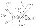
본발명에서는 직기의 경사를 개구상태가 되게하고 이 개구상태에서는 제3(a)도에 표시한 바와같이 압출부재 53의 선단 53a를 직포에 가볍게 접촉시켜서 직포를 따라 위사 1-2본분의 거리 내지 수 cm의 거리직전(織前)방향으로 이동시킨다.In the present invention, the inclination of the loom is brought into an open state. In this open state, as shown in FIG. Move in the direction just before the distance of several centimeters.
상하의 경사 21a, 21b가 개구하고 있으므로 상술한 바와 같이 최후에 위입되 위사 44b는 직포중의 위사 44a와의 사이에 소간극을 형성하고 있다.Since the upper and
이 때문에 직포상을 접촉이동한 압출부재 53의 선단 53a를 그 압하력(押下力)에 의하여 직포와 위사 44b사이의 소간극에 침입시킬 수가 있다. ("제3b도" 참조)For this reason, the
압출부재 53을 다시 직포로부터 멀어지는 방향으로 이동시킴으로써 위사 44b를 직포로부터 분리시키고 그 결과 적절한 뽑아내기 수단 또는 사람손에 의하여 이 위사를 용이하게 제거시킬 수가 있다. 또한 압출부재 53의 선단은 직포를 따라 위사 1-2분 내지 수 cm의 범위의 거리에 걸쳐서 접동(摺動)시키는 것은 직성 조직에 의하여 직전위치가 약간 전후로 변동되거나 또는 동일한 직포의 직폭방향으로 직전위치가 약간 변화되어 있어도 직포와 최후위입된 위사간의 소간극에 압출부재 53의 선단을 확실하게 삽입시켜서 최후위입되 위사를 확실하게 압출할 수 있기 때문이다.By moving the
따라서 상술한 바와같은 변동이 적은 경우에는 접동거리를 극히 작게할 수도 있다.Therefore, when the above-mentioned fluctuations are small, the sliding distance can be made extremely small.
상술한 방법을 실시하는 장치를 제1도, 제2도 및 제4도를 참조하여 설명한다.An apparatus implementing the above-described method will be described with reference to FIGS. 1, 2 and 4.
제1도는 본발명에 관한 애어 젯트직기의 구동계의 개요를 표시하는 측면도로서 종래의 장치와 마찬가지로 구동모우터 11로부터 V 밸트 13과 같은 전동부재를 개재시켜서 크랭크샤프트 15에 동력이 전달된다.1 is a side view showing an outline of a drive system of an air jet loom according to the present invention, and power is transmitted to the
크랭크샤프트 15는 변속기 17을 개재시켜서 야안비임 19를 구동시켜 경사 21을 풀어내고 또 서패이스로울러 31에 의하여 권취로울러 32를 마찰구동시켜서 직포 33을 권취시킨다.The
상기한 변속기 17은 장력로울러 23의 변위에 따라서 변속비가 조정되며 백로울러 22를 지나 송출되는 경사의 장력을 소정치(値)가 되도록 한다. 크랭크샤프트 15는 종광틀 24를 상하동시켜서 경사 21에 필요한 개구운동을 행하게 한다.The transmission ratio of the
또 록킹샤프트 29는 슬래이스워드 28을 개재하여 슬래이 27을 지지하며 슬래이 27에는 바디 25 및 위입가이드 26이 착설되어 있다.In addition, the locking shaft 29 supports slae 27 via the
크랭크 샤프트 15는 록킹샤프트 29를 개재하여 바디 25와 우입가이드 26을 실선위치와 파선위치사이에서 이동시키고 이에 따라서 바디 25가 위입된 위사를 비이팅시킨다. 이상의 구성은 종래의 애어 젯트직기와 동일하다.The
다음에 제2제도를 참조하여 위입기구를 설명한다.Next, the transfer mechanism will be described with reference to the second system.
치이즈 41로부터 텐서 42를 지나서 공급로울러 43에 의하여 위사 44는 풀려나와서 애어노즐 45에 의하여 풀파이프 46속에 저류(貯留)된다.The weft 44 is released by the
측장드럼 50은 크랭크샤프트 15(제1도)로 연동되고 있음과 동시에 공급로울러 43을 마찰구동시키고 있으며 크랭크샤프트 15(제1도)의 회전에 따라서 소정된 길이의 위사 44가 공급로울러 43에 의하여 측장되어 애어 노즐 45에 공급된다.The measuring drum 50 is interlocked with the crankshaft 15 (FIG. 1) and at the same time frictionally driving the
풀파이프 46은 그 한쪽에 측방향의 슬리트 47을 가졌으며 풀파이프 46속에 저류된 위사 44는 이슬리트 47로부터 끌어낼 수가 있다.The full pipe 46 has a slit 47 on one side and the weft 44 stored in the full pipe 46 can be pulled out of the islet 47.
또한 상술한 공급로울러와 풀파이프를 조합시킨 측장저류기구 대신에 예를들면 일본 특허공개공보중 공개번호 특개소 57-16946호나 특개소 58-58028호에 개시(開示)된 측장드럼의 주면에 위사를 감고 이 측장드럼으로부터 풀려나오는 것을 제어하도록 구성한 측장저류기구를 사용하여도 좋다.In addition, instead of the above-described measuring storage mechanism in which the supply roller and the pull pipe are combined, for example, wefts on the main surface of the measuring drum disclosed in Japanese Patent Application Laid-Open No. 57-16946 or 58-58028 May be used to control the holding and control of the release from the measuring drum.
풀파이프 46 및 매인 애어 젯트노즐 49사이에 그립퍼 48을 설치하여 풀파이프 46으로부터 매인 애어 젯트노즐 49로 위사 44가 공급되는 것을 제어하게 한다.A gripper 48 is installed between the full pipe 46 and the main air jet nozzle 49 to control the supply of the weft 44 from the full pipe 46 to the main air jet nozzle 49.
매인 에어젯트 노즐 49는 크랭크 샤프트 15(제1도)의 회전과 동기적(同期的)으로 압축공기를 분사하여 상하경사 21 사이에 형성된 저구속으로 위사 44를 위입하고 바디 25로 비이팅한다.The main air jet nozzle 49 injects compressed air synchronously with the rotation of the crankshaft 15 (FIG. 1) and injects the weft 44 into the
매인 애어젯트 노즐 49의 반대쪽의 이사(耳絲)부근에 위사 44가 확실히 위입되었는지 여부를 검출하는 광전식, 기계식 또는 유체식 등의 적당한 형식의 검출기 51,52를 설치하여 예를들면 일본 특허공보중 공고번호 특공소 54-21475호에 기재된 방법에 따라서 매인 애어 젯트노즐 49로부터 위사 44가 확실하게 공급되고 있음을 검출한다.A Japanese patent publication is provided by installing a suitable type of detector 51,52 such as a photoelectric, mechanical or fluid type that detects whether or not the weft 44 is securely inserted near the moving side of the main jet nozzle 49 It is detected that the weft yarn 44 is reliably supplied from the main air jet nozzle 49 in accordance with the method described in Heavy Publication No. 54-21475.
매인 애어젯트노즐 49와 이사와의 사이에 압축공기의 작용에 의하여 흡인력을 일으킬 수 있는 공지의 이젝터 타입의 흡인노즐 61이 설치된다. 이 흡인노즐 61에는 애어실린더 또는 전자솔레노이드등의 적당한 왕복운동부재 62가 연결되고 이 왕복운동부재 62의 작동에 의하여 흡인노즐 61의 선단이 매인 애어 젯트노즐 49로부터 사출되는 위사의 경로로부터 떨어진 위치와 위사경로 근방의 위치사이를 이동할 수 있다.A suction nozzle 61 of a known ejector type is provided between the main air jet nozzle 49 and the moving member to generate a suction force by the action of compressed air. The suction nozzle 61 is connected to a suitable reciprocating member 62 such as an air cylinder or an electromagnetic solenoid, and the position of the suction nozzle 61 is separated from the path of the weft from which the tip of the suction nozzle 61 is ejected from the main air jet nozzle 49 by the operation of the reciprocating member 62. You can move between locations near the weft path.
흡인노즐 61의 선단에 유도판 63을 착설하여 흡인노즐 61이 후퇴하였을 때에는 이 유도판 63이 위사의 경로로부터 벗어나있게 하고 또한 흡입노즐 61이 전진하면 유도판 63이 위사경로에 교차되도록 한다.The
흡인노즐 61의 후단에는 사복(蛇腹)형식의 신축연결구 66이 연결되어 있고 이 흡인노즐 61의 이동이 원활하게 행하여지도록 한다.The rear end of the suction nozzle 61 is connected to the expansion-and-collective connector 66 of the plain clothes type, and this suction nozzle 61 is moved smoothly.
또한 전기한 흡인노즐 61 및 여기에 일체적으로 형성된 유도판 63은 직기의 전후방향으로 운동하는 것에 한하는 것이 아니고 예를들면 상하방향으로 회동하는 형식의 것이라도 좋다.The suction nozzle 61 and the
65는 흡인노즐 61속을 향한 공기의 흐름의 분출을 제어하는 밸브이다.65 is a valve for controlling the flow of air toward the suction nozzle 61.
매인 에어 젯트노즐 49와 그립퍼 48과의 사이에 전자솔레노이드 71 또는 애어실린더(도시되지 않음) 등에 의하여 개폐작동되는 보조그립퍼 72를 설치한다.Between the main air jet nozzle 49 and the gripper 48, an auxiliary gripper 72 which is opened and closed by an electronic solenoid 71 or an air cylinder (not shown) is installed.
73은 광전식, 기계식 또는 유체식의 필러이다. 전술한 공급로울러 43은 핀 81의 둘레를 회동가능하게 지지된 아암 83의 선단에 지지되어 있다.73 is a photoelectric, mechanical or fluid filler. The
아암 83의 공급로울러 43지지단과 반대쪽의 단부에는 스프링 85을 착설하여 항상 애어실린더 86의 피스턴 또는 전자솔레노이드의 아마튜어의 선단에 아암 83이 닿아서 접하도록 부세(付勢)시킨다.A spring 85 is installed at the end opposite to the
따라서 스프링 85 및 애어실린더 86의 작용에 의하여 공급로울러 43은 측장드럼 50에 압압되어 마찰구동되는 상태 및 측장드럼 50으로부터 멀어져서 측장드럼 50에 의하여 구동되지 않는 상태를 취할수가 있다.Therefore, the
87은 측장드럼 50으로부터 멀어지게 된 공급로울러 43에 마찰접촉하여 제동을 가하기 위한 브래이크슈이다. 직기에는 위사절단용캇터가 착설되어 있다.87 is a brake shoe for applying friction braking to the
이 위사절단용캇터에 있어서는 정상운전시에는 고정칼과 크랭크샤프트에 연동하는 가공칼에 의하여 가이드의 파지요부(凹部)에 보지된 위사를 절단한다.In this weft cutting cutter, the weft held by the holding portion of the guide is cut by a fixed knife and a processing knife linked to the crankshaft during normal operation.
한편 이상정지신호가 발신되면 위사는 가이드의 요부(凹部)에 보지되지 않고 가동칼과 고정칼사이에서 절단되지 않게되는 구조를 하고 있다.On the other hand, when the abnormal stop signal is transmitted, the weft thread is not held by the recessed portion of the guide and is cut off between the movable knife and the fixed knife.
다음에 압출부재의 구성을 제4도를 참조하면서 설명한다.Next, the structure of an extrusion member is demonstrated, referring FIG.
직기의 직폭보다 긴 빔(beam : 梁)부재 76은 양단이 한상의 종간 74(제4도)에 의하여 지지되고 직기의 직포의 위쪽 또는 아래쪽에 설치된다.The
비임부재 76에는 직폭, 직물조직, 실의재질, 또 아암부재의 전후방향의 이동스트로우크에 따라서 직폭의 중앙에 하나 또는 직폭방향으로 간격을 둔 복수의 아암부재 54가 고착되며 이 아암부재 54의 선단에 압출부재 53이 핀 55에 의하여 회동가능하게 착설되어 있다.The
셀배이지 부근의 아암부재 54로 부터 일체적으로 돌출된 브라켓트 77에 나합된 보울트 78의 선단이 종간 74에 형성된 돌기 74a에 계합됨으로써 아암부재 54는 종간 74와 일체적으로 운동한다.The tip of the bolt 78, which is integral with the
스프링 79는 보울트 78의 선단을 돌기 74a 방향으로 부세시키는 것으로 보울트 78이 돌기 74a로부터 떨어져 있으면 스프링 79에 의하여 암부재 54에 적당한 압하력이 작용한다.The
각 아암부재 54에 일체적으로 형성한 브라켓트 56에 보울트 57을 나합시키고 그 선단이 △자상을 한 압출부재 53의 배면을 압압하도록 되어있다. 스프링 58은 압출부재 53을 보울트 57에 압압시키는 것이다.The
종간 74를 지축 75의 둘레에 회동 가능하게 지지시키고 있으며, 그 하단에 애어실린더 등의 유체압실린더 67의 피스턴롯드 68을 핀 64로 연결시키고 있다. 이 유체압실린더 67은 핀 64에 의하여 프레임에 지지되어 있다.The longitudinal section 74 is rotatably supported around the
또한 유체압실린더는 직기의 프레임의 양측에 설치하여도 좋고 또는 제2도에 표시한 바와 같이 한쪽에만 설치하여도 좋다.In addition, the fluid pressure cylinder may be provided on both sides of the frame of the loom, or may be provided only on one side as shown in FIG.
유체압실린더 67의 피스턴롯드 68의 작동방향을 제어하기 위하여 프레임에 리미트 스윗치 88,89가 착설되어 있다.Limit switches 88,89 are mounted on the frame to control the direction of operation of the
유체압실린더 67의 피스턴롯드 68의 후퇴중에 종간 74에 착설된 독그(도시되지 않음)가 리미트 스윗치 89를 치면 피스턴롯드 68은 전진한다. 전기한 독그가 리미트 스윗치 88을 치면 피스톤롯드 68은 다시 후퇴한다. 필요에 따라서 이 동작을 여러번 반복하여도 좋다.During retreat of
또한 상술한 리미트스윗치 88,89에 의한 제어 대신에 컴퓨터에 의한 제어를 하여도 좋다.Instead of the control by the limit switches 88 and 89 described above, control by a computer may be performed.
다음에 본발명의 이상정지시의 위사처리방법의 실시예를 설명한다.Next, a description will be given of an embodiment of a weft treatment method for abnormal stop of the present invention.
종광틀 24를 개구운동시켜서 상하경사 21 사이에 형성된 저구속으로 위사 44를 위입시킨다.The weft yarn 44 is enclosed with a low restraint formed between the upper and
즉, 제2도에서 치이즈 41로부터 텐서 42를 지나 풀려나온 위사 44는 크랭크샤로트 15(제1도)의 회전에 따라서 회전하는 공급로울러 43에 의하여 측장된후 애어노즐 45(제2도)에 의하여 풀파이프 46속으로 저류된다.In other words, the weft yarn 44 released from the cheese 41 through the tensor 42 in FIG. 2 is measured by the
풀파이프 46과 매인 애어 젯트 노즐 49와의 사이에 설치된 그립퍼 48과 매인 애어젯트노즐 49를 크랭크샤프트 15(제1도)의 회전에 동기적으로 작동제어시켜서 매인 애어 젯트노즐49로부터 분사되는 압축공기에 의하여 전기한 풀파이프 46속에 저류된 위사 44를 상하경사 21사이에 형성된 저구속으로 위입시킨다.The compressed air injected from the main air jet nozzle 49 is operated by controlling the gripper 48 and the main air jet nozzle 49 installed between the full pipe 46 and the main air jet nozzle 49 synchronously with the rotation of the crankshaft 15 (FIG. 1). The weft yarn 44 stored in the above-mentioned full pipe 46 is enclosed into a low bond formed between the up and down
매인 애어젯트 노즐 49와 반대쪽의 이사부근에 설치된 검출기 51,52는 경사 21가 거의 폐구시(크랭크 각도 250-300도)에 위입상태를 체크하고 어떤 원인에 의하여 저구에 위입된 위사가 매인 애어젯트노즐 49의 반대쪽의 이사까지 도달되지 않은 위입미스가 생기면 검출기 51,52가 위입미스 신호를 발한다.The detector 51,52 installed near the main jet nozzle 49 and near the moving side checks the intrusion state when the
이 위입미스신호에 의하여 직기를 구동하는 모우터 11(제1도)의 운전이 정지되고 관성운전에 들어간다. 또 위입미스신호가 발신되면 왕북운동부재 62의 피스턴이 전진하여 흡인노즐 61 선단에 착설된 유도판 63을 위사의 경로에 교차시킨다.The operation of the motor 11 (FIG. 1) which drives the loom stops by this false input signal, and enters inertia operation. In addition, when the upper miss signal is transmitted, the piston of the north north movement member 62 moves forward to intersect the
이와같이 하여 위입미스후에 매인 애어 젯트 노즐 49로부터 분출되는 위사는 유도판 63에 안내되어 흡인노즐 61에 이르게 되고 이 흡인노즐 61에 흡인된다. 또한 위사절단용 캇터의 절단기능을 일시적으로 부작동되게하고 위입미스된 위사가 젯트노즐로부터 이어진 상태가 되게 한다.In this manner, the wefts ejected from the main air jet nozzle 49 after the inlet miss are guided to the
따라서 위입미스 신호발신후의 위입은 저지되고 위사가 저구로부터 흡인노즐 61을 경유 매인 애어젯트노즐 49에 이어진 상태가 된다.Therefore, gastric infiltration after gastric miss signal transmission is inhibited, and the weft thread is connected to the air jet nozzle 49 via the suction nozzle 61 via the mouth.
관성운전하고 있던 직기는 약 1사이클 작동한 후 경사 21이 겨의 폐구한 상태(크랭크 각도 약 300도)에서 정지한다.The loom in inertial operation operates about one cycle, and then stops when the inclined 21 is closed by the chaff (crank angle approximately 300 degrees).
이어서 역(회)전 준비에 들어간다. 즉, 매인 애어 젯트노즐 49를 부작동상태가 도게 한다. 그립퍼 48을 닫고 또는 전자솔레노이드 71에 의하여 보조그립퍼 72를 닫는다.Then, we prepare for the station turn. That is, the main air jet nozzle 49 is brought into a non-operational state. Close the gripper 48 or close the auxiliary gripper 72 by the solenoid 71.
또한 애어실린더 86을 작동시켜서 공급로울러 43을 측장드럼 50으로부터 멀어지게하여 위사공급기구를 부작동되게 한다.In addition, the air cylinder 86 is operated so that the
한편, 왕복운동부재 62의 피스턴을 후퇴시켜서 흡인노즐 61의 선단의 유도판 63을 위사의 경로로부터 벗어나게 한다. 이 상태에서 구동모우터 11(제1도)을 직접 역(회)전시키거나 또는 구동모우터 11과는 별도로 설치된 보조모우터(도시되지 않음)를 작동시켜서 기대(機臺) 약 480도 역(회)전시킴으로써 경사 21을 개구상태가 되게 한다(크랭크 각도 약 180도).On the other hand, the piston of the reciprocating member 62 is retracted so that the
이와같은 개구상태에서 압출부재를 위사와 직포와의 사이의 소간극에 삽입시킴으로써 위입미스된 위사를 직포로부터 분리시킨다.In such an open state, the extruded weft yarn is separated from the woven fabric by inserting the extruded member into the small gap between the weft and the woven fabric.
또한 압출부재의 압출 개시신호는 전술한 위입미스 신호등의 정지신호 발신후 소정의 시간이 경과되면 타임머로 발신시키도록 하여도 좋고 기대를 역회전시켜서 개구상태가 되면 리미트 스윗치 등으로부터의 신호로 발신되도록 하여도 좋고 또는 사람의 손에 의하여 압단추를 눌러서 발신하여도 좋다.In addition, the extrusion start signal of the extruded member may be sent to the timer when a predetermined time elapses after the stop signal of the above-mentioned false inlet signal or the like. This may be done, or by pressing a push button by a human hand.
정상운전시에는 제4(a)도에 표시한 바와같이 유체압실린더 67의 피스턴롯드 68을 돌출시켜두며 종간 74는 지축 75의 둘레를 시계방향으로 회동하고 있게 해둔다.In normal operation, as shown in FIG. 4 (a), the
보울트 78의 선단은 돌기 74a에 계합되고 보울트 57의 선단은 압출부재 53의 배면에 계합되며 압압부재 53의 선단은 직포로부터 떨어져 있으며 압압부재 53은 정상운전중의 젯트직기의 제직작업을 전혀 방해하지 않는다.The tip of the bolt 78 is engaged with the projection 74a, the tip of the
전술한 정지신호에 의하여 직기가 정지하고 상하의 경사 21a, 21b가 개구상태에서 정지하여 압출개시 신호가 발신되면 유체압실린더 67의 피스턴롯드 68이 후퇴한다.When the loom is stopped by the stop signal described above, the
이에 따라 종간 74는 지축 75의 둘레를 반시계방향으로 회동한다.As a result, the section 74 rotates around the
이때에 압출부재 53의 선단이 직포에 접촉하게 될때까지는(제4"b"도 참조)압출부재 53, 아암부재 54 그리고 종간 74가 일체가 되어 회동한다. 그리고 압출부재 53이 직포에 접촉하면 압출부재 53의 하강운동이 방해되고 압출부재 53은 핀 55의 둘레를 회동하여 압출부재 53이 보울트 57로부터 떨어진다.At this time, the extruding
이 결과 스프링 58에 의하여 압출부재 53의 선단은 소정의 압압력으로 직포에 접촉한다.As a result, the tip of the
유체압실린더 67의 피스턴롯드 68이 다시 후퇴하고 종간 74가 다시 반시계 방향으로 회동됨과 동시에 압출부재 53의 선단은 적당한 정도의 압압력으로 직포위를 접동(摺動)한다.The
압압부재 53의 선단이 직포와 최종위입된 위사 44(제3"a"도, 제3"b"도 참조) 사이의 소간극에 이르면 스프링 58 혹은 경우에 따라서는 스프링 79의 탄발력에 의하여 소간극에 압압부재 53의 선단을 침입시킨다. (제4"c"도 참조)When the tip of the pressing
골듀로 이와같이 직포의 직물조직이 조밀하면 경사를 개구시킴으로써 위사와 직포와의 사이에 형성되는 소간극이 극히 작아지고 이때문에 압출부재가 소간극에 확실하게 침입할 수 없을때가 있다.If the fabric structure of the woven fabric is dense as described above, the small gap formed between the weft and the woven fabric is extremely small by opening the warp, and thus the extruded member cannot reliably enter the small gap.
그리하여 유체압실린더 67의 피스턴롯드 68이 후퇴하여 리미트 스윗치 89를 치면 피스턴롯드를 재차 전진시키게 된다.Thus, when the
이에 따라서 압출부재 53의 선단은 직포에 따라 전술한 방향과는 역방향으로 접동한다.Accordingly, the tip of the
리미트 스윗치 88을 치면 재차 압출부재 53의 선단은 직포를 따라 직전을 향하여 최초의 방향으로 접동하여 나간다.When the limit switch 88 is hit, the tip of the extruded
압출부재가 한번 소간국에 침입한 경우에는 압출부재에 의하여 간극이 넓혀져 있게 될 것이므로 한번 압출부재가 간극을 벗어나도 다음번의 접동동작에 의하여 압출부재의 선단은 소간극에 확실하게 침입된다.If the extruded member enters the small space once, the gap will be widened by the extruded member, so that the tip of the extruded member will certainly enter the small gap by the next sliding action even if the extruded member leaves the gap once.
한편 전술한 바와 같이 직물조직이 조밀하여 간극이 작고 이 간극에 압출부재가 침입할 수 없었던 경우에도 최초의 접동동작시에 압출부재 53의 선단에 의하여 위사 44b는 직전으로부터 떨어져 간극이 증가되는 방향으로 눌려진다.On the other hand, as described above, even when the fabric structure is dense and the gap is small, and the extrusion member cannot penetrate the gap, the weft yarn 44b is separated from the last by the tip of the
이 때문에 다음에 압출부재 53이 도달하였을 때에는 간극이 넓혀져 있어 압출부재 53은 요번에는 용이하게 간극에 침입할 수가 있다.Therefore, when the
또 압출부재가 접동시에 위사에 주는 접동저항은 충분히 적으므로 압출부재의 후퇴에 의하여 열어진 간극이 좁아지는 일은 없다.Moreover, since the sliding resistance given to the weft yarn by the extrusion member when sliding is sufficiently small, the gap opened by the retraction of the extrusion member is not narrowed.
이 압출부재가 소간극에 삽입된 상태에서 유체압실린더 67의 피스턴롯드 68을 다시 후퇴시킴으로써 압출부재 53은 위사 44b를 직포로부터 분리시킨다.By retracting the
또한 위사 44b가 직포에 단단하게 보지되어 있는 경우에는 이 위사 44b를 직포로부터 분리시키는 동작을 전술한 바와 같이 반복시킨다.In the case where the weft 44b is held firmly in the woven fabric, the operation of separating the weft 44b from the woven fabric is repeated as described above.
이 반복 동작은 위사와 그것을 단단하게 잡고 있는 경사 21a,21b와의 사이에 말하자면 진동작용을 줌으로써 경사의 위사 44b에 대한 보지력을 어느정도 약화시키고 그 결과 위사가 직포로부터 용이하게 분리될 수 있다.This repetitive operation slightly weakens the holding force of the warp weft 44b by vibrating, as it is, between the weft yarn and the
이와 같이하여 분리된 위사는 이미 경사에 단단하게 잡혀져 있지 않으므로 예를들면 흡인노즐 61과 같은 적당한 뽑아내기 수단에 의하여 또는 사람손에 의하여 용이하게 뽑아내어 제거시킬 수가 있다.Since the wefts separated in this way are not already held firmly on the inclination, they can be easily pulled out and removed by means of a suitable extraction means such as, for example, a suction nozzle 61 or by a human hand.
실을 이와같이하여 제거시킨후 자동적 또는 사람손에 의하여 스윗치 온 시킴으로써 경사 21이 폐구된 상태(크랭크 각도 약 270도)까지 기대를 약 270도 역(회)전시켜 애어 젯트직기의 기동에 적당하게 한다.After the thread is removed in this manner, the switch is turned on automatically or by human hand to reverse the expectations about 270 degrees until the inclined 21 is closed (crank angle about 270 degrees), making it suitable for maneuvering the Air Jet loom. .
이어서 매인 애어 젯트노즐 49를 작동상태가 되게 한다.The Main Air Jet Nozzle 49 is then brought into operation.
전자솔레노이드 71을 비여자(非勵磁)상태가 되게 하여 보조그립퍼 72를 열고, 한편 그립퍼 48도 정상작동상태가 되게 한다.The electronic solenoid 71 is made non-excited to open the auxiliary gripper 72, while the gripper 48 is also brought into normal operation.
또한 애어실린더 86의 피스턴을 후퇴시켜 공급로울러 43을 측장드럼 50의 주면에 압압시켜서 위사공급기구를 작동상태가 되게한다.In addition, the piston of the air cylinder 86 is retracted, and the
이상에서 애어 젯트직기의 운전을 재개시킨다.The operation of the air jet loom is restarted.
본 발명의 방법을 실시하는 다른 장치를 제5도를 참조하여 설명한다. 제4도에 표시한 장치에서는 유체압 실린더의 왕복운동을 제어하여 압출부재 53의 운동을 여러번 반복하도록 하고 있다.Another apparatus for implementing the method of the present invention is described with reference to FIG. In the apparatus shown in FIG. 4, the reciprocating motion of the hydraulic cylinder is controlled to repeat the movement of the
한편, 제5도에 표시한 장치에서는 압출부재 53에 핀 92에 의하여 자(子) 압출부재 91을 회동가능하게 지지시키고 이 자압출부재 91을 압출부재 53에 대하여 회동시켜서 압출부재 53 및 자압출부재에 91에 의하여 전체로서 압출부재의 운동을 반복시키고 있다.On the other hand, in the apparatus shown in FIG. 5, the
즉, 핀 95에 의하여 종간 74에 레버 94를 회동가능하게 지지하고 있다.That is, the
이 레버 94의 하단에 전자솔레노이드 96의 아마튜어 또는 유체압실린더의 피스턴롯드와 같은 왕복운동부재를 연결시키고 있다.The lower end of the
또 레버 94의 상단에는 핀 98에 의하여 연결간 93을 연결하고 있다.The upper end of the
이 연결간 93은 핀 97에 의하여 자압출부재 91에 연결되어 있다.The connection 93 is connected to the self-
따라서 왕복운동부재를 왕복시킴으로써 자압출부재 91은 레버 94 및 연결간 93에 의하여 핀 97의 둘레를 회동한다.Thus, by reciprocating the reciprocating member, the self-
또한 자압출부재 91의 작동 타이밍은 전술한 실시예와 마찬가지로 선정하고 컴퓨터 또는 리미트 스윗치등으로 제어하면 된다.The operation timing of the self-
이상의 설명에서는 위입미스된 위사의 수복(修復)의 예에 대하여 설명하였으나 본발명은 경사끊김, 이사끊김, 또는 인위적 조작에 의한 애어젯트직기기의 정지시에도 적용 가능하다.In the above description has been described an example of restoring the weft missed weft, the present invention can be applied to the stop of the jet loom machine by the inclination break, moving break, or artificial manipulation.
본발명에 의하여 젯트직기의 정지시의 위사제거가 확실하게 행하여지고 위사제거를 완전하게 또한 거의 완전자동화시킬 수가 있다.According to the present invention, weft removal at the stop of the jet loom can be reliably performed, and weft removal can be completely and almost completely automated.
Claims (4)
Applications Claiming Priority (2)
| Application Number | Priority Date | Filing Date | Title |
|---|---|---|---|
| JP125844 | 1982-07-21 | ||
| JP57125844A JPS5921753A (en) | 1982-07-21 | 1982-07-21 | Weft yarn treatment at stop time of jet loom |
Publications (2)
| Publication Number | Publication Date |
|---|---|
| KR840007259A KR840007259A (en) | 1984-12-06 |
| KR860001418B1 true KR860001418B1 (en) | 1986-09-23 |
Family
ID=14920338
Family Applications (1)
| Application Number | Title | Priority Date | Filing Date |
|---|---|---|---|
| KR1019830003351A KR860001418B1 (en) | 1982-07-21 | 1983-07-20 | Weft operating apparatus during stopping of jet loom |
Country Status (2)
| Country | Link |
|---|---|
| JP (1) | JPS5921753A (en) |
| KR (1) | KR860001418B1 (en) |
Families Citing this family (2)
| Publication number | Priority date | Publication date | Assignee | Title |
|---|---|---|---|---|
| JPH01166937U (en) * | 1988-05-16 | 1989-11-22 | ||
| JPH0531198U (en) * | 1991-09-26 | 1993-04-23 | 富士通テン株式会社 | Mounting structure of conductive plate to electronic equipment |
-
1982
- 1982-07-21 JP JP57125844A patent/JPS5921753A/en active Granted
-
1983
- 1983-07-20 KR KR1019830003351A patent/KR860001418B1/en not_active IP Right Cessation
Also Published As
| Publication number | Publication date |
|---|---|
| JPS5921753A (en) | 1984-02-03 |
| KR840007259A (en) | 1984-12-06 |
| JPS6237139B2 (en) | 1987-08-11 |
Similar Documents
| Publication | Publication Date | Title |
|---|---|---|
| US4502512A (en) | Method for treating a weft yarn upon stoppage of a shuttleless loom and device for effecting the same | |
| KR860002101B1 (en) | Weft operating method & apparatus in jet loom | |
| KR860001411B1 (en) | Protection method of difect weft weaving in the shuttless loom | |
| JPH0343378B2 (en) | ||
| US4711273A (en) | Loom | |
| EP0332258A1 (en) | Method for removing a loose incorrect piece of weft thread from the shed on weaving machines | |
| KR860001418B1 (en) | Weft operating apparatus during stopping of jet loom | |
| JPS633986B2 (en) | ||
| US5209271A (en) | Mispicked weft removing method | |
| US4899788A (en) | Apparatus for removing a faulty weft yarn from a weaving shed | |
| KR860001417B1 (en) | Weft operating apparatus during stopping of jet loom | |
| JPS6262167B2 (en) | ||
| JPH0689498B2 (en) | Miss yarn removing device for jet looms | |
| EP0517664A1 (en) | Weft handling apparatus in a shuttleless loom | |
| KR100324193B1 (en) | Weaving gripping device of the loom | |
| EP0150763A2 (en) | Loom | |
| JPH0663160B2 (en) | Method and device for processing defective wefts in shuttleless loom | |
| JP2503546Y2 (en) | Weft cutting avoidance device in loom | |
| JPS6262166B2 (en) | ||
| JPS62141158A (en) | Method for treating yarn in shuttleless loom | |
| JPH11323698A (en) | Drive unit for selvedge control element | |
| JPS58220850A (en) | Weft yarn treating apparatus of jet loom | |
| JPH0635695B2 (en) | Weft processing method for shuttleless loom | |
| JPH0336548Y2 (en) | ||
| JPH0329904B2 (en) |
Legal Events
| Date | Code | Title | Description |
|---|---|---|---|
| A201 | Request for examination | ||
| G160 | Decision to publish patent application | ||
| E701 | Decision to grant or registration of patent right | ||
| GRNT | Written decision to grant | ||
| FPAY | Annual fee payment |
Payment date: 19931214 Year of fee payment: 9 |
|
| LAPS | Lapse due to unpaid annual fee |