KR860000172B1 - Jacking apparatus having a fast repositioning stroke - Google Patents
Jacking apparatus having a fast repositioning stroke Download PDFInfo
- Publication number
- KR860000172B1 KR860000172B1 KR8205647A KR820005647A KR860000172B1 KR 860000172 B1 KR860000172 B1 KR 860000172B1 KR 8205647 A KR8205647 A KR 8205647A KR 820005647 A KR820005647 A KR 820005647A KR 860000172 B1 KR860000172 B1 KR 860000172B1
- Authority
- KR
- South Korea
- Prior art keywords
- cylinder
- piston
- fluid
- jacking
- pressure
- Prior art date
Links
Images


Classifications
-
- B—PERFORMING OPERATIONS; TRANSPORTING
- B63—SHIPS OR OTHER WATERBORNE VESSELS; RELATED EQUIPMENT
- B63C—LAUNCHING, HAULING-OUT, OR DRY-DOCKING OF VESSELS; LIFE-SAVING IN WATER; EQUIPMENT FOR DWELLING OR WORKING UNDER WATER; MEANS FOR SALVAGING OR SEARCHING FOR UNDERWATER OBJECTS
- B63C3/00—Launching or hauling-out by landborne slipways; Slipways
- B63C3/08—Tracks on slipways
-
- B—PERFORMING OPERATIONS; TRANSPORTING
- B66—HOISTING; LIFTING; HAULING
- B66F—HOISTING, LIFTING, HAULING OR PUSHING, NOT OTHERWISE PROVIDED FOR, e.g. DEVICES WHICH APPLY A LIFTING OR PUSHING FORCE DIRECTLY TO THE SURFACE OF A LOAD
- B66F1/00—Devices, e.g. jacks, for lifting loads in predetermined steps
- B66F1/02—Devices, e.g. jacks, for lifting loads in predetermined steps with locking elements, e.g. washers, co-operating with posts
- B66F1/04—Devices, e.g. jacks, for lifting loads in predetermined steps with locking elements, e.g. washers, co-operating with posts the posts being toothed
- B66F1/08—Devices, e.g. jacks, for lifting loads in predetermined steps with locking elements, e.g. washers, co-operating with posts the posts being toothed and the devices being operated by fluid pressure
-
- B—PERFORMING OPERATIONS; TRANSPORTING
- B66—HOISTING; LIFTING; HAULING
- B66F—HOISTING, LIFTING, HAULING OR PUSHING, NOT OTHERWISE PROVIDED FOR, e.g. DEVICES WHICH APPLY A LIFTING OR PUSHING FORCE DIRECTLY TO THE SURFACE OF A LOAD
- B66F3/00—Devices, e.g. jacks, adapted for uninterrupted lifting of loads
- B66F3/24—Devices, e.g. jacks, adapted for uninterrupted lifting of loads fluid-pressure operated
- B66F3/25—Constructional features
- B66F3/26—Adaptations or arrangements of pistons
-
- F—MECHANICAL ENGINEERING; LIGHTING; HEATING; WEAPONS; BLASTING
- F15—FLUID-PRESSURE ACTUATORS; HYDRAULICS OR PNEUMATICS IN GENERAL
- F15B—SYSTEMS ACTING BY MEANS OF FLUIDS IN GENERAL; FLUID-PRESSURE ACTUATORS, e.g. SERVOMOTORS; DETAILS OF FLUID-PRESSURE SYSTEMS, NOT OTHERWISE PROVIDED FOR
- F15B11/00—Servomotor systems without provision for follow-up action; Circuits therefor
- F15B11/02—Systems essentially incorporating special features for controlling the speed or actuating force of an output member
- F15B11/028—Systems essentially incorporating special features for controlling the speed or actuating force of an output member for controlling the actuating force
- F15B11/036—Systems essentially incorporating special features for controlling the speed or actuating force of an output member for controlling the actuating force by means of servomotors having a plurality of working chambers
- F15B11/0365—Tandem constructions
-
- F—MECHANICAL ENGINEERING; LIGHTING; HEATING; WEAPONS; BLASTING
- F15—FLUID-PRESSURE ACTUATORS; HYDRAULICS OR PNEUMATICS IN GENERAL
- F15B—SYSTEMS ACTING BY MEANS OF FLUIDS IN GENERAL; FLUID-PRESSURE ACTUATORS, e.g. SERVOMOTORS; DETAILS OF FLUID-PRESSURE SYSTEMS, NOT OTHERWISE PROVIDED FOR
- F15B2211/00—Circuits for servomotor systems
- F15B2211/20—Fluid pressure source, e.g. accumulator or variable axial piston pump
- F15B2211/205—Systems with pumps
- F15B2211/2053—Type of pump
- F15B2211/20538—Type of pump constant capacity
-
- F—MECHANICAL ENGINEERING; LIGHTING; HEATING; WEAPONS; BLASTING
- F15—FLUID-PRESSURE ACTUATORS; HYDRAULICS OR PNEUMATICS IN GENERAL
- F15B—SYSTEMS ACTING BY MEANS OF FLUIDS IN GENERAL; FLUID-PRESSURE ACTUATORS, e.g. SERVOMOTORS; DETAILS OF FLUID-PRESSURE SYSTEMS, NOT OTHERWISE PROVIDED FOR
- F15B2211/00—Circuits for servomotor systems
- F15B2211/30—Directional control
- F15B2211/305—Directional control characterised by the type of valves
- F15B2211/3056—Assemblies of multiple valves
- F15B2211/30565—Assemblies of multiple valves having multiple valves for a single output member, e.g. for creating higher valve function by use of multiple valves like two 2/2-valves replacing a 5/3-valve
-
- F—MECHANICAL ENGINEERING; LIGHTING; HEATING; WEAPONS; BLASTING
- F15—FLUID-PRESSURE ACTUATORS; HYDRAULICS OR PNEUMATICS IN GENERAL
- F15B—SYSTEMS ACTING BY MEANS OF FLUIDS IN GENERAL; FLUID-PRESSURE ACTUATORS, e.g. SERVOMOTORS; DETAILS OF FLUID-PRESSURE SYSTEMS, NOT OTHERWISE PROVIDED FOR
- F15B2211/00—Circuits for servomotor systems
- F15B2211/30—Directional control
- F15B2211/31—Directional control characterised by the positions of the valve element
- F15B2211/3122—Special positions other than the pump port being connected to working ports or the working ports being connected to the return line
-
- F—MECHANICAL ENGINEERING; LIGHTING; HEATING; WEAPONS; BLASTING
- F15—FLUID-PRESSURE ACTUATORS; HYDRAULICS OR PNEUMATICS IN GENERAL
- F15B—SYSTEMS ACTING BY MEANS OF FLUIDS IN GENERAL; FLUID-PRESSURE ACTUATORS, e.g. SERVOMOTORS; DETAILS OF FLUID-PRESSURE SYSTEMS, NOT OTHERWISE PROVIDED FOR
- F15B2211/00—Circuits for servomotor systems
- F15B2211/70—Output members, e.g. hydraulic motors or cylinders or control therefor
- F15B2211/705—Output members, e.g. hydraulic motors or cylinders or control therefor characterised by the type of output members or actuators
- F15B2211/7051—Linear output members
- F15B2211/7055—Linear output members having more than two chambers
- F15B2211/7056—Tandem cylinders
Landscapes
- Engineering & Computer Science (AREA)
- Mechanical Engineering (AREA)
- Physics & Mathematics (AREA)
- Fluid Mechanics (AREA)
- Life Sciences & Earth Sciences (AREA)
- Geology (AREA)
- Structural Engineering (AREA)
- General Engineering & Computer Science (AREA)
- Ocean & Marine Engineering (AREA)
- Actuator (AREA)
- Centrifugal Separators (AREA)
- Making Paper Articles (AREA)
- Dowels (AREA)
- Waveguide Aerials (AREA)
- Manufacturing Of Electrical Connectors (AREA)
- Conveying And Assembling Of Building Elements In Situ (AREA)
Abstract
Description
제1도는 본 발명을 구체화한 재킹장치의 평면도.1 is a plan view of a jacking device embodying the present invention.
제2도는 제1도 재킹장치의 정면도.2 is a front view of the first jacking device.
제3도는 파우어행정중 실린더로 부터나 실린더에로의 유체의 흐름을 설명한 제도의 재킹장치에 대한 실린더 배치의 개략도.3 is a schematic diagram of a cylinder arrangement for a drafting jacking device illustrating the flow of fluid to and from the cylinder during the power stroke.
제4도는 귀환행정중에 유체의 실린더에로의 유동 및 실린더로부터의 유동을 도시한 제3도와 유사한 개략도.FIG. 4 is a schematic similar to FIG. 3 showing the flow of fluid into and out of the cylinder during the return stroke.
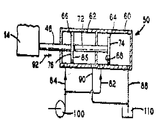
제5도는 제1도 재킹장치의 유체공급과 되돌림장치 및 실린더의 개략도.5 is a schematic diagram of the fluid supply and return device and cylinder of the first jacking device.
제6도는 본 발명의 다른 구체적 예를 도시한 제4도와 유사한 개략도.6 is a schematic view similar to FIG. 4 showing another specific example of the present invention.
* 도면의 주요부분에 대한 부호의 설명* Explanation of symbols for main parts of the drawings
10 : 함재데크(barge deck) 12 : 진수로10: barge deck 12: by the launch
20 : 재킹장치 22 : 앵커지점20: jacking device 22: anchor point
28, 34 : 도그(dog) 30, 32 : 하우징28, 34: dog 30, 32: housing
60, 62 : 실린더 64, 66 : 피스톤60, 62:
100 : 펌프100: pump
본 발명은 무거운 물체를 효과적으로 이동시키기 위한 재킹 장치에 관한 것으로, 특히 유압장치를 이용하여 무거운 물체를 이동시키는 재킹장치에 관한 것이다.The present invention relates to a jacking device for effectively moving a heavy object, and more particularly to a jacking device for moving a heavy object using a hydraulic device.
산업적 계획의 실시 중에 때때로 무거운 물체를 한곳으로부터 다른 곳으로 이동시킬 필요가 있다. 예컨대, 해상응용에 있어서 무거운 보우트 또는 해안유정탐사 플래트홈(platform)을 물속에 진수시키기 위해 진수로를 따라 보우트 또는 플래트홈을 이동시켜야 한다. 이러한 경우에 무거운 물체를 이동시키는데 필요한 힘을 얻기 위해 유압실린더를 이용한 재킹장치가 사용되어지는 바, 일반적인 재킹장치에 있어서는 이동시킬 물체가 각종의 상호 연결구조를 통해서 피스톤 내에 있는 피스톤의 맞은편 양쪽에 부착되어 있는 피스톤로드에 부착되어 있다.It is sometimes necessary to move heavy objects from one place to another during the implementation of an industrial plan. For example, in maritime applications, the boat or platform must be moved along the launching path to launch a heavy boat or offshore oil exploration platform into the water. In this case, a jacking device using a hydraulic cylinder is used to obtain the force required to move a heavy object. In a typical jacking device, the object to be moved is provided on both sides of the piston in the piston through various interconnection structures. It is attached to the attached piston rod.
본 명세서 및 특허청구 범위에서 "실린더"라 함은 별도로 명시되지 않은 한 피스톤 또는 피스톤로드(piston rod) 부분을 포함한 것을 의미하지 않는다.In the present specification and claims, "cylinder" does not mean including a piston or piston rod portion unless otherwise specified.
실린더는 피스톤의 파우어행정(힘을 제공받는 행정) 중 물체를 이동시키고자 하는 방향의 반대방향으로의 이동되는 것을 방지하기 위해 장치를 지지하는 구조 내 또는 구조 위에 있는 여러개의 앵커지점(anchor point)에 고정된다. 여기에서 "파우어행정(power point)"이라 함은 물체를 이동시키는 피스톤 행정을 의미하는 것으로 파우어행정 중에 앵커지점에서 실린더가 정지되므로 피스톤은 이동하게 된다. 이것은 파우어행정중에 준비상태인 재킹장치의 이동이라고 칭하는 "귀환행정"과는 구별되는 것으로서 되돌림 행정중에, 실린더는 이동하는 물체와 피스톤은 정지된 채로 있는다.The cylinder has several anchor points in or on the structure that supports the device to prevent movement of the piston in the opposite direction to which the object is to be moved during the power stroke (forced stroke). Is fixed to. Here, "power point" refers to a piston stroke for moving an object, and the piston moves because the cylinder is stopped at the anchor point during the power stroke. This is distinguished from the "return stroke", which is referred to as the movement of the jacking device that is ready during the power stroke, and during the return stroke, the cylinder moves and the piston remains stationary.
압력유체가 파우어행정 중에 실린더에 공급되면 유체(액체)는 피스톤의 한쪽 측면과 이에 대응하는 반대측 실린더 벽체 사이에 힘을 가하게 되고, 실린더는 실린더벽체에 가해지는 유체의 압력이 실린더의 벽에 가해지므로서 이에 대한 방향으로 실린더가 이동되는 것을 방지하기 위해 앵커지점에서 고정시키므로 물체를 이동시키고자 하는 방향으로 피스톤을 이동시키게 된다. 따라서 물체는 피스톤이 파우어행정 중에 이동하는 거리와 실질적으로 동일한 거리만큼 원하는 방향으로 이동된다.When a pressure fluid is supplied to the cylinder during the pneumatic stroke, the fluid (liquid) exerts a force between one side of the piston and the corresponding cylinder wall on the opposite side, and the cylinder exerts a pressure on the wall of the cylinder that is applied to the cylinder wall. Since the cylinder is fixed at the anchor point to prevent the cylinder from moving in this direction, the piston is moved in the direction to move the object. The object is thus moved in the desired direction by a distance substantially equal to the distance the piston travels during the powder stroke.
이런 형태의 공통된 재킹장치의 있어서는 귀환행정을 시키기 위해 재킹장치를 앵커지점과 분리시키기 위한 규제가 취해지고 귀환행정을 시키기 위해 압력유체를 피스톤의 다른 측면과 이에 대응하는 반대측 실린더벽 사이에 가해지게 되는데, 이러한 장치는 통상적으로 이동시킬 물체보다 사실상 가벼워서 실질적으로 보다 적은 저항을 주므로 실린더벽에 작용하는 유체의 압력은 물체가 먼저 이동한 것과 같은 방향으로 실린더와 장치의 나머지 부분(물론, 피스톤에 부착된 장치의 부분 및 피스톤은 제외됨)을 이동시키게 된다. 이 지점에서, 다른 앵커지점 또는 앵커지점의 셋트(set)는 결합되어 물체를 원하는 방향으로 또 다른 한정된 거리로 이동시키기 위한 다른 파우어행정을 위해 장치를 준비시키게 된다.In a common jacking device of this type, a restriction is made to separate the jacking device from the anchor point for the return stroke, and a pressure fluid is applied between the other side of the piston and the corresponding opposite cylinder wall for the return stroke. These devices are typically virtually lighter than the object to be moved, giving them substantially less resistance, so that the pressure of the fluid acting on the cylinder wall is reduced to the cylinder and the rest of the device (of course, Parts of the device and pistons are excluded). At this point, another anchor point or set of anchor points are combined to prepare the device for another power stroke to move the object another desired distance in the desired direction.
실린더와 유압펌프장치는 특정한 속도에서 파우어행정을 하는 중에 최대로 큰 물체를 이동시킬 수 있는 크기로 할 수 있는데 종래의 전형적인 재킹장치에 있어서의 실린더 및 유체공급장치는 파우어행정중에 피스톤의 한측면에 유압을 가하고, 귀환행정중에 피스톤의 달느 측면에 유압을 가하며 이때 피스톤의 각각 반대쪽의 유체는 대응하는 각 행정마다 저장탱크(sump)에 복귀된다. 재크장치는 통상적으로 이동시킬 물체보다 사실상 가벼우므로 귀환행정중에 재크장치의 이동을 위한 가능한 힘은 재킹장치를 이동시키는데 필요한 힘보다 실질적으로 더 크다. 그러나, 귀환행정시에 이러한 전형적인 재킹장치의 속도는 귀환행정의 속도뿐 아니라 파우어행정의 속도가 유압의 실린더내내로 흘러 들어가는 속도비에 좌우되므로 제한된다.The cylinder and hydraulic pump device can be sized to move the largest object during the power stroke at a certain speed. The cylinder and fluid supply device in the conventional jacking device is provided on one side of the piston during the power stroke. Hydraulic pressure is applied, and hydraulic pressure is applied to the other side of the piston during the return stroke, in which the fluid on each side of the piston is returned to the sump at each corresponding stroke. Since the jacking device is typically substantially lighter than the object to be moved, the possible force for the movement of the jacking device during the return stroke is substantially greater than the force required to move the jacking device. However, the speed of this typical jacking device in the return stroke is limited because not only the speed of the return stroke but also the speed ratio of the power stroke flows into the hydraulic cylinder.
거대한 해안유정탐사플래트홈을 적재하거나 진수시키기 위한 재저작등에 소요되는 시간은 대부분 파우어 행정 및 귀환행정의 연속에 의해 걸리는 시간으로 30시간 또는 40시간을 필요로 하고, 이러한 조작(작용)은 여러가지의 예인선과 크레인을 이용하며 이러한 재크조작을 위해서는 통틀어 30명 또는 40명의 사람이 필요하다. 만일 이러한 조작에 있어서 각각의 귀환행정에 요구되는 시간이 약 절반으로 절약될 수 있다면 그 결과는 많은 시간을 절약할 수 있을 뿐만 아니라 비용을 크게 절감시킬 수 있을 것이다.Most of the time spent reloading or launching a huge offshore oil well exploration platform requires 30 hours or 40 hours, which is the time taken by a series of power administration and return administrations. Tugboats and cranes are used and these jacking operations require a total of 30 or 40 people. If the time required for each return administration in this operation can be saved in about half, the result will not only save a lot of time, but also greatly reduce the cost.
그러므로, 본 발명은 각 귀환행정에 요구되는 시간을 줄이기 위해 주어진 펌프용량에서 최대속도의 귀환행정을 제공하는 유압실린더 유체공급장치를 갖춘 재킹장치를 제공하는 것이다.It is therefore an object of the present invention to provide a jacking device with a hydraulic cylinder fluid supply device that provides a maximum speed feedback stroke at a given pump capacity to reduce the time required for each feedback stroke.
본 발명을 첨부된 도면과 함께 상세히 설명하면 다음과 같다.The present invention will be described in detail with reference to the accompanying drawings as follows.
제1도 및 제2도는 중량이 많이 나가는 배 또는 해안 유정탐사 플래트홈과 같은 물체(14)를 지지하고 이동시키기 위해 진수로(12)의 셋트(도면에는 하나만 표시되어 있음)와 같은 지지구좀루이 세워져 있는 함재테크(10)를 나타낸 것으로, 진수로(12)는 물체가 쉽게 슬라이딩 이동할 수 있도록 면 마찰계수가 낮은 테프론수지와 같은 재질로 이루어져 물체를 이동시키고자 하는 방향(제1도 및 제2도에서 좌측으로부터 우측 또는 우측으로부터 좌측중 어느 하나의 방향)으로 뻗어 있으며, 각 진수로(12)는 재킹빔(16)과 같은 하나 또는 그 이상의 부재에 따라 소정의 방향으로 물체를 슬라이딩 이동시키기 위해 한쌍의 재킹장치(20)뿐 아니라 물체(14)를 지지한다. 이후 이 방향(제1도 및 제2도에서 우측으로부터 좌측 또는 좌측으로부터 우측중 하나의 방향)을 종축방향이라 칭하기로 한다. 재킹범(16)에 수직방향으로 뚫어져 있는 슬로트(slot)로 된 다수의 앵커지점은 파우어행정중의 이동에 반해 각 재크장치(20)를 고정시키기 위한 수단을 제공하는 것으로서, 재킹빔(16)은 물체(14)를 안내하는데 도움되게 하기 위해 각 진수로(12) 측부에 연하여 연장되고 각 진수로(12)보다 약간 더 높은 것이 바람직하다.Figures 1 and 2 show a support piece, such as a set of launching furnaces 12 (only one is shown in the drawing) for supporting and moving
각 재킹빙(16)의 앵커지점(22)의 다음 선단은 제1도에서 간격(18)으로 표시된 거리만큼 종축방향으로 떨어져 위치하는데 각 재킹장치(20)의 파우어행정 또는 귀환행정의 길이와 대략 같은 것이 바람직하지만 적을 수도 있다.The next tip of the
여기서 각 재킹장치(20)는 사실상 동일하고 실질적으로 동일한 방법으로 작동하므로 이후에는 하나의 재킹장치만을 설명코자 한다. 물체를 재킹장치(20)에 결속시키기 위하여서 피(26)을 포함한 여러가지 수단이 제공되는데, 이러한 물체의 결속수단은 물체를 원하는 방향으로 이동시키기 위해 물체(14)를 결속시킬 수 있는 일종의 결속 메카니즘으로 구성되는 것으로서 예컨대, 물체를 밀어내기 위해 램(ram)을 갖출 수도 있다.Here, since each jacking device 20 operates in substantially the same and substantially the same manner, only one jacking device will be described later. Various means are provided to bind the object to the jacking device 20, including the
진수로(12)로부터 데크에 전달되는 재킹력을 지지하기 위해 데크(10)에 전단부재(도시되지 않음)을 용접시킨 다음 전단부재 사이에 진수로 지지체를 위치시켜 전단부재와 접촉되어 종축방향으로 진수로 지지체를 이동시키는 제지부재에 의해 진수로 지지체가 수직으로 움직이지 못하게 되어 있고, 다음에 전단부재는 상기 지지체가 종축방향으로 움직이지 못하도록 되어 있다.A shear member (not shown) is welded to the deck 10 to support the jacking force transmitted from the
따라서, 전단부재의 사용은 진수로(12)를 데크에 부착시키는 과정과 데크의 다른 위치에 부착하기 위해 데크로부터 이탈시키는 방법을 간소화시킨다. 재킹장치(20)에는 하나 이상의 하우징(32) 내에 움직일 수 있도록 내장되어 있는 도그(28)와 같은 앵커지점 결속수단이 갖추어져 이것이 빔(16) 위에 있는 각각의 앵커지점에 결속되어 재킹장치가 이동되는 것을 저지하여 앵커지점에 힘이 가해질 때 물체(14)가 이동되도록 하고, 반대측 종축방향에서 앵커지점(22)에 힘이 가해질 때에는 재킹장치(20)가 이동될 수 있도록 할다.Thus, the use of the shear member simplifies the process of attaching the
제2도에서와 같이 도그(28)는 하우징(32)에서 제거될 수 있는데 각 하우징(32)의 개구부(33)에 일정한 방향으로 삽입되어진다. 상기 도그(28)는 종축방향으로 저면이 경사진 특징이 있는데, 도그(28)를 제거하고 삽입시키는 통상 과정을 돕기 위해 호이스트장치를 설치하기 위한 세발기둥소켓트(29)가 갖추어져 있으며, 이들 도그(28)는 제2도에 도시된 바와 같이 물체(14)에 근접하여 위치한 저면(36)의 최하위점(38)과 각 하우징(32)의 저면을 지나서 삽입되는 저면(36)의 상당한 부분이 각 개구부(33)에 삽입되어 앵커지점인 각각의 슬로트와 결합시키므로서 재킹장치(20)의 이동을 저지하여 물체(14)를 화살표(40) 방향으로 이동시키게 된다. 그러나, 제2도에 도시된 바와 같이, 도그(28)를 삽입시킴에 따라 재크장치(20)에 화살표(40) 방향으로 힘이 가해질 때(후에 설명될 재킹장치 내에 가해지는 압력유체에 의해 이루어짐)이 방향으로 재킹장치(20)가 이동되지 못하게 하지만 그 대신에 도그(28)가 앵커지점(22)으로부터 이탈하여 빔(16)의 표면위를 미끄러져 종축 방향으로 떨어져 있는 다른 앵커지점(22)에 결합된다.As shown in FIG. 2, the dog 28 may be removed from the housing 32 and inserted into the opening 33 of each housing 32 in a predetermined direction. The dog 28 is characterized in that the bottom surface is inclined in the longitudinal axis direction, is provided with a tri-pole socket 29 for installing a hoist device to help the normal process of removing and inserting the dog 28, these dogs 28 shows the lowermost point 38 of the bottom 36 located in proximity to the
또한 제2도에 도시된 도그(28)는 각각의 개구부(33)와 앵커지점(22)에 삽입되기 전에 180도로 회동하여 이의 최하위점(38)을 물체(14)로부터 가장 멀리 떨어져 물체로부터 멀어지는 방향으로 재킹장치(20)가 이동하려는 것을 저지시키므로서 물체(14)로부터 가장 멀리 떨어져 물체로부터 멀어지는 방향으로 재킹장치(20)가 이동하려는 것을 저지시키므로서 물체(14)가 화살표(44) 방향으로 이동되게 한다. 여기서는 비록 한 형태의 앵커지점과 앵커지점 결합수단이 기술되었지만 다른 형태의 수단도 사용할 수 있으며, 이들 역시 본 발명의 범위에 속하는 것으로 예를 들면, 래크(Rack)와 포올(Pawl) 혹은 캘리퍼시스템(Caliper system)이 제공되어 질수 있다.The dog 28 shown in FIG. 2 also rotates 180 degrees before being inserted into each opening 33 and
재크장치(20)의 이동에 저항하도록 앵커지점(22)과 실린더 구조(50) 사이에 힘을 전달하기 위하여서 하우징(32)이 관통피(58) 및 부재(59)와 같은 수단에 의해 유압실린더 구조(50)에 연결되어 있다.In order to transfer the force between the
재크장치(20)가 제1도에서의 화살표방향(44)과 같이 물체(14)를 밀어내는데 사용될 경우에는 잭크장치(20)를 물체(14)에 부착시키지 않는 것이 바람직하다. 다시 말해서, 물체(14)는 재크장치(20)에 부착되지 않은채로 피스톤로드 구조에 부착된 램에 의해 밀려지게 하는 것이 바람직하다. 이러한 경우에 도그(28)는 하우징(32)의 각 개구부(33)로 삽입되어질 수 있고 물체(14)로부터 가장 멀리 떨어진 각 저면(36)의 최하위점(38)과 다음의 슬로트(22)에 삽입될 수 있다. 파우어행정중에 물체(14)는 화살표 방향(44)으로 밀려질 수 있는 한편, 실린더구조(50)는 도그(28)에 의해 확고히 정지될 수 있다. 본 발명의 바람직한 실시예에 따라 유압실린더구조(50)의 피스톤로드부분(46)은 핀(52)과 같은 수단을 통해서 다른 하우징(20)의 일측부에 연결된다. 도그(28)와 유사한 제거가능한 도그(34)는 하우징(30)의 각개구부(31)에 삽입된다. 이들 도그(34)는 로우드과 피스톤 로드구조에 부착되지 않거나 이동에 대항하는 피스톤 로드구조를 고정시키는데 너무 가벼울 때 귀환행정시 이동에 대항하는 피스톤 로드구조를 고정시키기 위한 수단을 제공하도록 물체(14)로부터 가장 멀리 떨어진 각 저면(37)의 최하위점(39)으로 각 슬로트(22)와 하우징(30) 내에 삽입될 수 있다. 하우징(30)은 피스톤로드부분(46)과 물체(14) 사이에 힘을 전달하기 위해 핀(26)을 통해서 물체(14)에 연결된다.It is preferable not to attach the jack device 20 to the
특정한 크기의 실린더보어(bore)를 위해 증가된 출력을 제공하기 위해서는 재크장치실린더구조(50)에 제5도에 도시된 바와 같이 직렬로 배치된 적어도 하나의 제1실린더(60)와 적어도 하나의 제2실린더(62)를 포함한 최소한 도 개의 2중작용을 하는 유압실린더의 그룹이 제공되는데, 이들 실린더(60) 및 (62)의 각각에는 피스톤(64) 및 (66)이 각각 제공된다. 이중작용 실린더라 함은 유압이 어느 측부에서나 피스톤에 가해질 수 있는 실린더와 피스톤의 결합체를 의미하고, 직렬실린더 장치라 함은 통상의 피스톤로드배치에 의해 연결된 피스톤과 일렬로 고정된 두개 또는 그 이상의 실린더를 의미한다. 실린더(60) 및 (62)의 이중작용조작을 허용하기 위해 통상의 로드 실(rod seals)(도시되어 있지 않음) 사이에 장치된다.In order to provide increased output for a cylinder bore of a particular size, at least one of the
제5도에 도시된 바와 같이, 피스톤로드부분(46)은 제2실린더(62)의 각 피스톤(66)의 제1측부(76)에 연장된다. 또 다른 피스톤로드부분(72)은 제2실린더피스톤(66)의 제2측부(86)로부터 제1실린더(60) 각 피스톤(64)의 제1측부(68)에 연장된다.As shown in FIG. 5, the piston rod portion 46 extends to the
상술한 바와 같은 직렬실린더장치는 최대의 작업 압력이 동일한 보어 크기의 단일실린더로 낼 수 없는 필요한 출력을 내도록 제한하는 경우에 바람직한 것으로 고려될 수 있다. 예컨대, 15평방인치(97㎠)의 피스톤 면적을 가진 실린더는 몰리적으로 특수한 기계를 적재할 수 있는 가장 큰 보어크리고 될 수 있다. 아직 가능한 최대의 작업압력은 평방인치당 500 파운드(㎠당 29kg)에 불과하며 기계는 10,000파운드(3, 700kg)의 저항을 제공하는 로우드를 이동시키는데 필요하다. 직렬실린더장치는 그 장치가 15평방인치(572㎠) 면적의 피스톤과 3평방인치(23㎠) 면적의 피스톤로드를 가진 두개의 실린더로 구성된 경우에 사용될 수 있다. 15평방인치 면적의 피스톤 하나와 12평방인치(366㎠) 면적의 다른 피스톰에 작용하는 평방인치당 500파운드일 때 힘이 10,000파운드(3,700kg) 몰체를 이동시키기에 충분한 무거운 물체를 이동시키는 데는 13,500파운드(5,000kg)의 힘이 내어진다.The serial cylinder device as described above may be considered to be desirable when the maximum working pressure is limited to yield the required output which cannot be achieved by a single cylinder of the same bore size. For example, a cylinder with a piston area of 15 square inches (97 cm 2) can be the largest borer that can rationally load a special machine. The maximum possible working pressure is still only 500 pounds per square inch (29 kg per cm 2) and the machine is needed to move the rods providing 10,000 pounds (3,700 kg) of resistance. The tandem cylinder device can be used when the device consists of two cylinders having a piston of 15 square inches (572 cm 2) and a piston rod of 3 square inches (23 cm 2). At 500 pounds per square inch acting on a piston of 15 square inches and another piston of 12 square inches (366 cm 2), 13,500 force is required to move a heavy object sufficient to move a 10,000 pound (3,700 kg) mass. Pounds (5,000kg).
유압펌프(100)와 같은 유체공급수단은 실린더(60) 및 (62)의 그룹에 예정된 유속으로 유압을 제공한다. 유압 실린더의 한 그룹 이상이 단일수압펌프에 공급될 수 있으므로 유압실린더(60) 및 (62)의 그룹에 대한 예정된 유속은 펌프의 총출력유속보다 적을 수 있다. 예컨대, 만일 단일펌프가 두 그룹의 유압실린더를 동등하게 공급한다면 한 그룹의 유압실린더에 대한 유체의 예정된 유속은 펌프의 총출력유속의 절반으로 될 것이다. 유속이라 함은 배관의 교출부를 지나서 흐르는 유체의 분당 겔론(gallons)수와 같은 단위시간당 주어진위치로 또는 위치를 지나서 흐르는 애체의 용량을말한다.Fluid supply means such as
이 배관은 접합부로부터 한 그룹의 유압실린더의 각각에 흐르는 분지관을 갖는다. 원하는 방향으로 물체이동을 위해 최대량의 힘을 제공하도록 유압실린더(60)과 (62)사이에 유체의 예정된 유속을 할당하고 유체의할당된 유속을 일정하게 하기 위해 장치들에 제공된다. 보다 신속한 귀환행정을 위해 실린더(60)과 (62)그의룹의 하나에 유체의 증가된 유속을 제공하기 위해서 실린더(60)와 (62)그룹의 하나에만 유체의 에정된 유속룹모두 일정하게 하기 위한 본 발명에 따라 장치들이 제공된다.This pipe has a branch pipe flowing from each joint to each of a group of hydraulic cylinders. Devices are provided to assign a predetermined flow rate of the fluid between the
실질적인 모든 예정된 유속이라 함은 본 발명의 목적과 청구를 위해 예정된 유속의 적오도75%를 의미하는 것으로 예컨대, 예정된 유속의 50%는 다른 실린더에 대해서와 같이 전환될 수 있으며 그 장치는 본 발명의 범위에 속함을 의미하는 것이다.Substantially all predetermined flow rates refer to an equatorial 75% of the intended flow rate for the purposes and claims of the present invention, for example 50% of the predetermined flow rate can be converted as for other cylinders and the apparatus of the invention It means belonging to a range.
또한 유압이 되돌림행정중에 저항을 받거나 배체되는 실린더에 진공형성을 방지하기 위한 수단에 제공되는것이 바람직하다.It is also desirable that hydraulic pressure be provided in the means for preventing vacuum formation in the cylinder being resisted or drained during the return stroke.
제3도에 도시된 바와같이 본 발명의 바람직한 실시예 따라 유압은 액체배관(82)및 (84)를 각각 통해서 양피스톤(64)및 (66)의 제1측부(68)및 (76)에 가해지고, 유체는 92로 표시된 종축방향으로 물체(14)를 이동시키도록 파우어행정을 위해 유체라인(88, 90)을 각각 통해서 양피스톤(64)및 (66)의 제2측부(74)및 (86)으로부터 배출됨으로써 실린더 (60)이 (62)는 앵커지점 결합수단에 의해 이동이 억제되며 피스톤(64)및 (66)은 방향(92)로 이동된다.According to a preferred embodiment of the present invention, as shown in FIG. 3, the hydraulic pressure is applied to the
제4도에 도시된 바와같이, 보다 신속한 귀환 행정을 위해 실린더내에 유체에 유속을 증가시키기 위하여 유압을 본 발명에 따라 배관(88)을 통해서 제1실린더 피스톤(64)의 제2측부에 가해지는 한편, 제2실린더스톤(74)의 제2측부에도 적용하는 유압은 앵커지점 결속수단이 귀환행정동안 앵커지점을 분리시키므로써 생기는 실린더(66)및 실린더(94)의 운동이 방향(74)으로 일어나므로써 최소한 저지당하거나 바람직하게배제되어진다.As shown in FIG. 4, hydraulic pressure is applied to the second side of the
한편, 피스톤(64)및 (66)의 제1측부(68)및 (76)에 대한 유체는 각각 배관(82)및 (84)를 통해서 배출된다. 배관(82)을 통해서 피스톤(64)의 제1측부(68)로부터 배출된 액체는 필요에 따라 저장탱크에 유입될지라도 보다 신속한 귀환행정을 위해 피스톤(64)의 제2측부(74)에 유체의 보다 빠른 유속을 제공하도록 배관(88)으로 유입되게 하는 것이 좋다.On the other hand, the fluid to the
제4도에 도시된 바와같이, 이러한 귀환행정중에 압력은 동시에 제1실린더피스톤(64)의 양측부에 가해진다. 이것은 외관상 실린더를 유압식으로 로크된 상태로 하지만 유압에 노출된 제1측부(68)상의 피스톤면적과 유압에 노출된 제2측부(74)상의 피스톤면적 사이의 차이는 방향(94)으로 실린더(60)(62)의 이동을 위해 피스톤(64)의제2측부(74)에 가해지는 보다 큰 힘을 생기게 하는 결과가 된다. 그러므로 제1실린더 피스톤(64)의제1측부(68)상의 실린더용적이 감소하므로 제1실린더 피스톤(64)의 제1측부(68)로부터 액체의 배출이 생기게 된다.As shown in FIG. 4, during this return stroke, pressure is applied to both sides of the
그러므로 이와 같이 배출된 액체는 배관(88)에 유입된 후 펌프(100)에 의해 제1실린더 피스톤(64)의 제2측부에 공급되는 유체와 합쳐진다.Therefore, the discharged liquid is introduced into the
제2실린더피스톤(66)의 제2측부(86)에서 진공형성으로 인해 귀환행정의 속도가 감소되거나 정지되는 것을지하기 위하여 제2실린더피스톤(66)의 제2측부(86)는 제4도에 도시된 바와 같이 배관(84)및 (90)을 통해서 제2실린더피스톤(66)의 제1측부(76)또는 저장탱크(101)에 연결되거나 또는 양측에 연결되는것이하다. 제5도는 제3도및 제4도에 도시된 파우어행정 및 귀환행정을 제공하는데 바람직한 수단을 나타낸것인바 이러한 수단을 제1및 제2의실린더(60) 및 (62)의 각각에 공용되는 방향 밸브(96) 및 (98)을 포함한다펌프(100)와 같은 유체공급수단은 배관(101)을 통해서 유압실린더(60) 및 (62)의 그룹에 예정된 유속으로 유압을 제공하고, 분지관(102) 및(104)은 배관(101)으로부터 방향밸브(96) 및 (98)에 각각 연장된다 또한 펌프(100)는 관통배관(103) 및 (105)과 같은 유압실린더의 다른그룹에 유체를 추가함으로써 유압을 제공할 수도 있다.The second side portion 86 of the
분지관(106) 및 (108)은 저장탱크(110)에 액체의 배출을 위해 방향밸브(110)에 각각 연결된다.
방향밸브(96) 및 (98)는 각각 (112) 및 (113)으로 각각 표시된 파우어행정피스톤과 (114) 및 (115)로 각각 표시된 귀환행정피스톤을 갖는다. 방향밸브(96) 및 (98)는 (116)으로 표시된 방향으로 실린더(6) 및 (62)의 이동을 위해 제5도에서 귀환행정피스톤이 도시되어 있다.
파우어행정피스톤(112) 및 (113)은 각 배관(102) 및 (104)를 배관(82) 및 (84)와 연결하여 유압실린더(60) 및 (62) 사이의 배관(101)을 통해서 펌프(100)으로부터 흐르는 유체의 예정된 유속을 할당하고 유체의 할당된 유속을 각 피스톤(64) 및 (66)의 각 제1축부(68) 및 (76)에 배분한다. 제5도에 도시된 바와 같이, 파우어행정피스톤 (112) 및 (113)은 각 배관(88) 및 (00)을 저장탱크(110)에 안내하는 배관(106) 및 (108)과 연결하여 각 피스톤(64) 및 (66)의 각 축부(74) 및 (86)으로부터 유체를 배출되게 하는 것이 바람직하다.The
본 발명의 바람직한 실시예에 따라 귀환행정피스톤(115)은 배관(104)을 폐쇄 또는 차단하여 배관(104)을 통해서 제2실린더(62)에 유체의 유동을 배제시키고 귀환행정피스톤(114)은 배관(102)을 배관(88)과 연결시켜서 배관(101) 내에 흐르는 유체의 예정된 모든 유속을 귀환행정을 위해 제1실린더피스톤(64)의 제2축부(74)에 보낸다.According to a preferred embodiment of the present invention, the
제5도에 도시된 바와 같이, 또한 귀환행정피스톤(114)은 제1실린더피스톤(64)의 제1측부(68)로부터 배출되는 배관(82) 내에 흐르는 유체의 유동을 보다 신속한 귀환행정을 위해 배관(8)내로 보내는 것이 바람직하다. 또한 제5도에 도시된 바와 같이, 귀환행정피스톤(115)은 배관(90)을 저장탱크(110)에 배관(108)과 배관(84)을 연결하여 귀환행정중에 제2실린더피스톤(66)의 제2측부에 진공형성을 방지한다.As shown in FIG. 5, the
제6도는 본 발명의 다른 구체적 실시예를 위한 귀환행정을 설명한 것으로, 이 경우 유압실린더구조(150)는 제4도의 유압실린더구조(50)와 유사한 것이다.6 illustrates a return stroke for another specific embodiment of the present invention, in which case the
유압실린더구조(150)에는 피스톤로드 부분(172)에 의해 각각 연결된 피스톤(164) 및 (166)을 가지며 직렬로 배치된 제1 및 제2 이중작용 유압실린더(160) 및 (162)가 제공된다. 그러나, 이 구체적 실시예에서 피스톤로드부분(146)은 실린더구조(150)과 이동시키고자 하는 물체(14) 사이에 힘을 전담하기 위해 제1실린더피스톤(164)의 제2측부(174)로부터 연장된다. 유압은 예정된 유속을 제4도의 펌프(100)와 마찬가지로 펌프(190)에 의해 유압실린더구조(150)에 공급된다. 이 구체적 실시예에서 유체의 모든 예정된 유속은 배관(88)을 통해서 이 실린더 피스톤(164)의 제2측부(174)에 공급되고, 유체는 증가된 귀환행정을 위해 제2실린더(162)에의 유동으로부터 배출되는 한편 유체는 제4도는 저장탱크(110)와 마찬가지로 피스톤(164) 및 (166)의 제1측부(168) 및 (176)으로부터 각 배관(182) 및 (184)를 통해서 저장탱크(192)로 배출된다.The
제2실린더피스톤(166)의 제2측부(86)는 배관(190)을 통해서 저장탱크(192) 및 제2실린더 피스톤(166)의 제1측부(176)에 연결되어 진공형성을 방지하게 된다.The second side portion 86 of the
Claims (7)
Applications Claiming Priority (2)
| Application Number | Priority Date | Filing Date | Title |
|---|---|---|---|
| US06/331,737 US4506867A (en) | 1981-12-17 | 1981-12-17 | Jacking apparatus having a fast repositioning stroke |
| US331737 | 1981-12-17 |
Publications (2)
| Publication Number | Publication Date |
|---|---|
| KR840002734A KR840002734A (en) | 1984-07-16 |
| KR860000172B1 true KR860000172B1 (en) | 1986-02-28 |
Family
ID=23295167
Family Applications (1)
| Application Number | Title | Priority Date | Filing Date |
|---|---|---|---|
| KR8205647A KR860000172B1 (en) | 1981-12-17 | 1982-12-16 | Jacking apparatus having a fast repositioning stroke |
Country Status (8)
| Country | Link |
|---|---|
| US (1) | US4506867A (en) |
| EP (1) | EP0082676B1 (en) |
| JP (1) | JPS58109395A (en) |
| KR (1) | KR860000172B1 (en) |
| AU (1) | AU554581B2 (en) |
| DE (1) | DE3274669D1 (en) |
| IN (1) | IN157339B (en) |
| NO (1) | NO824239L (en) |
Families Citing this family (12)
| Publication number | Priority date | Publication date | Assignee | Title |
|---|---|---|---|---|
| JPS60148707U (en) * | 1984-03-10 | 1985-10-02 | 日本鉱機株式会社 | Heavy object moving equipment |
| DE3523944A1 (en) * | 1985-07-04 | 1987-01-15 | Dyckerhoff & Widmann Ag | Apparatus for moving heavy loads, e.g. parts of a structure, scaffolding or the like |
| US5098065A (en) * | 1987-12-22 | 1992-03-24 | Aldo Beletich | Mine extraction device and method |
| GB8905202D0 (en) * | 1989-03-08 | 1989-04-19 | Qualter Hall & Co Ltd | Power operated device |
| US5114861A (en) * | 1990-09-14 | 1992-05-19 | General Electric Company | Detecting the endpoint in interfacial aromatic polycarbonate polymerization reactions |
| CA2185378A1 (en) * | 1995-09-29 | 1997-03-30 | Joseph E. O'brien | Actuator for forming a flange on a wheelhouse |
| FI100677B (en) * | 1996-09-13 | 1998-01-30 | Multilift Oy | Method for controlling the speed of movement of hydraulically driven machine, drive system of hydraulically driven machine and control device |
| US6572080B1 (en) | 2001-06-15 | 2003-06-03 | Chris A. Delikatzis | Dual hydraulic jack system |
| JP5714341B2 (en) * | 2011-01-19 | 2015-05-07 | ナブテスコ株式会社 | Aircraft actuator |
| US20150217938A1 (en) * | 2014-02-05 | 2015-08-06 | Ventura Hydraulic & Machine Works, Inc. | Hydraulic Device With Heating Element |
| WO2016080874A1 (en) * | 2014-11-19 | 2016-05-26 | Saab Ab | A fluid actuator arrangement |
| EP3458726A4 (en) | 2016-05-19 | 2020-02-19 | Saab Ab | A fluid actuator arrangement and a method for control of a fluid actuator arrangement |
Family Cites Families (9)
| Publication number | Priority date | Publication date | Assignee | Title |
|---|---|---|---|---|
| US2517164A (en) * | 1947-02-19 | 1950-08-01 | Bruno F Arps | Two-speed hydraulic ram |
| US2962001A (en) * | 1958-11-07 | 1960-11-29 | Hartford Special Machinery Co | Hydro-pneumatic power mechanism |
| US3170379A (en) * | 1962-02-13 | 1965-02-23 | Dempster Brothers Inc | Hydraulic system |
| US3680713A (en) * | 1970-11-09 | 1972-08-01 | Snorkel Fire Equipment Co | Fluid power device |
| US4024794A (en) * | 1973-02-02 | 1977-05-24 | Amp Incorporated | Pneumatically operated cable-slitting tool |
| FR2309430A1 (en) * | 1975-05-02 | 1976-11-26 | Union Ind Entreprise | HANDLING DEVICE INTENDED FOR RIPING HEAVY LOADS |
| US4007915A (en) * | 1975-12-15 | 1977-02-15 | Hydranautics | Jacking apparatus |
| GB1568086A (en) * | 1976-03-05 | 1980-05-21 | Kosmala R | Hydraulic devices |
| US4296677A (en) * | 1979-06-25 | 1981-10-27 | Mcdonnell Douglas Corporation | Tandem hydraulic actuator |
-
1981
- 1981-12-17 US US06/331,737 patent/US4506867A/en not_active Expired - Lifetime
-
1982
- 1982-12-15 IN IN1444/CAL/82A patent/IN157339B/en unknown
- 1982-12-15 AU AU91560/82A patent/AU554581B2/en not_active Ceased
- 1982-12-16 KR KR8205647A patent/KR860000172B1/en active
- 1982-12-16 EP EP82306714A patent/EP0082676B1/en not_active Expired
- 1982-12-16 DE DE8282306714T patent/DE3274669D1/en not_active Expired
- 1982-12-16 NO NO824239A patent/NO824239L/en unknown
- 1982-12-17 JP JP57220399A patent/JPS58109395A/en active Pending
Also Published As
| Publication number | Publication date |
|---|---|
| EP0082676A2 (en) | 1983-06-29 |
| IN157339B (en) | 1986-03-01 |
| KR840002734A (en) | 1984-07-16 |
| JPS58109395A (en) | 1983-06-29 |
| EP0082676A3 (en) | 1983-11-30 |
| AU9156082A (en) | 1983-06-23 |
| US4506867A (en) | 1985-03-26 |
| AU554581B2 (en) | 1986-08-28 |
| EP0082676B1 (en) | 1986-12-10 |
| NO824239L (en) | 1983-06-20 |
| DE3274669D1 (en) | 1987-01-22 |
Similar Documents
| Publication | Publication Date | Title |
|---|---|---|
| KR860000172B1 (en) | Jacking apparatus having a fast repositioning stroke | |
| US4674914A (en) | Replacing mains | |
| KR920007709B1 (en) | Choke valve especlally used in oil and gas wells | |
| US4490096A (en) | Pump system for liquid/solid materials with balanced output | |
| NO320076B1 (en) | borehole Tractor | |
| US3266776A (en) | Hydraulic winch with self-clamping jaws | |
| EP0094395A1 (en) | An elevating apparatus. | |
| KR910007429B1 (en) | Pipe proepelling device | |
| EA008642B1 (en) | Tubular injector apparatus and method of use | |
| US4558629A (en) | Hydraulic control means for pipe thrust-jacking apparatus | |
| EP0324287B1 (en) | Pipe burster | |
| US10612377B2 (en) | Hydraulically operated splitting device | |
| US4379662A (en) | Control device for an advancing support in underground mining | |
| EP0082677B1 (en) | Jacking apparatus and force transmitting methods | |
| JP2840567B2 (en) | Method and apparatus for reducing surge motion between offshore structures | |
| US4474253A (en) | Apparatus for producing an upwardly directed drill hole | |
| SE444836B (en) | DEVICE ON MOUNTAIN OR EARTH DRILLING UNIT | |
| US4396072A (en) | Method and apparatus for producing a drill hole | |
| US3545204A (en) | Arrangements in the control system of hydrostatic winches of the low pressure type | |
| SU1652244A1 (en) | Hydraulic transport arrangement | |
| SU1041647A1 (en) | Method and apparatus for trenchless laying of pipelines | |
| SU1661300A1 (en) | Method and apparatus for trenchless laying of pipeline | |
| SU899918A1 (en) | Apparatus for boosting liquid pressure | |
| SU1186728A1 (en) | Arrangement for lifting hydraulic gate | |
| KR800000454B1 (en) | Placement method for q.d. charges using minimum diving time |