KR850001729B1 - Speed rachet - Google Patents
Speed rachet Download PDFInfo
- Publication number
- KR850001729B1 KR850001729B1 KR8204901A KR820004901A KR850001729B1 KR 850001729 B1 KR850001729 B1 KR 850001729B1 KR 8204901 A KR8204901 A KR 8204901A KR 820004901 A KR820004901 A KR 820004901A KR 850001729 B1 KR850001729 B1 KR 850001729B1
- Authority
- KR
- South Korea
- Prior art keywords
- ratchet
- plunger
- tool
- lever
- ratchet tool
- Prior art date
Links
Images


Classifications
-
- B—PERFORMING OPERATIONS; TRANSPORTING
- B25—HAND TOOLS; PORTABLE POWER-DRIVEN TOOLS; MANIPULATORS
- B25B—TOOLS OR BENCH DEVICES NOT OTHERWISE PROVIDED FOR, FOR FASTENING, CONNECTING, DISENGAGING OR HOLDING
- B25B13/00—Spanners; Wrenches
- B25B13/10—Spanners; Wrenches with adjustable jaws
- B25B13/12—Spanners; Wrenches with adjustable jaws the jaws being slidable
- B25B13/20—Arrangements for locking the jaws
- B25B13/22—Arrangements for locking the jaws by ratchet action or toothed bars
-
- B—PERFORMING OPERATIONS; TRANSPORTING
- B25—HAND TOOLS; PORTABLE POWER-DRIVEN TOOLS; MANIPULATORS
- B25B—TOOLS OR BENCH DEVICES NOT OTHERWISE PROVIDED FOR, FOR FASTENING, CONNECTING, DISENGAGING OR HOLDING
- B25B17/00—Hand-driven gear-operated wrenches or screwdrivers
-
- B—PERFORMING OPERATIONS; TRANSPORTING
- B25—HAND TOOLS; PORTABLE POWER-DRIVEN TOOLS; MANIPULATORS
- B25B—TOOLS OR BENCH DEVICES NOT OTHERWISE PROVIDED FOR, FOR FASTENING, CONNECTING, DISENGAGING OR HOLDING
- B25B13/00—Spanners; Wrenches
- B25B13/46—Spanners; Wrenches of the ratchet type, for providing a free return stroke of the handle
- B25B13/461—Spanners; Wrenches of the ratchet type, for providing a free return stroke of the handle with concentric driving and driven member
- B25B13/467—Spanners; Wrenches of the ratchet type, for providing a free return stroke of the handle with concentric driving and driven member which are gear-operated
-
- B—PERFORMING OPERATIONS; TRANSPORTING
- B25—HAND TOOLS; PORTABLE POWER-DRIVEN TOOLS; MANIPULATORS
- B25B—TOOLS OR BENCH DEVICES NOT OTHERWISE PROVIDED FOR, FOR FASTENING, CONNECTING, DISENGAGING OR HOLDING
- B25B13/00—Spanners; Wrenches
- B25B13/48—Spanners; Wrenches for special purposes
- B25B13/481—Spanners; Wrenches for special purposes for operating in areas having limited access
Abstract
Description
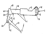
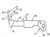
제1도는 본 발명의 일실시예에 따른 래칫공구의 평면도.1 is a plan view of a ratchet tool according to an embodiment of the present invention.
제2도는 제1도의 화살표(2)방향을 따라 취한 래칫공구의 측면도.2 is a side view of the ratchet tool taken along the direction of arrow 2 in FIG.
제3도는 부분적으로 나타낸 레버가 있는 제1도의 손공구의 배면도.3 is a rear view of the hand tool of FIG. 1 with the lever partially shown.
제4도는 제1도의 래칫공구의 단부면도.4 is an end view of the ratchet tool of FIG.
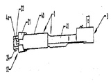
제5도는 덮개판이 제거되어 있는 제1도의 래칫공구의 평면도.5 is a plan view of the ratchet tool of FIG. 1 with the cover plate removed.
제6도는 제1도의 손공구의 손잡이의 단면도.6 is a cross-sectional view of the handle of the hand tool of FIG.
제7도는 공구용 구동체인과 중간 덮개판이 제거되어 있는 제1도의 손공구의 머리부분의 평면도.7 is a plan view of the head of the hand tool of FIG. 1 with the drive chain for the tool and the intermediate cover plate removed.
제8도는 제7도의 Ⅷ-Ⅷ선의 머리부분의 단면도.8 is a cross-sectional view of the head of the X-ray of FIG.
* 도면의 주요부분에 대한 부호의 설명* Explanation of symbols for main parts of the drawings
(1) : 관형상 몸체 (2) : 손잡이(1): tubular body (2): handle
(3) : 래칫구동요소 (4) : 플런저메카니즘(3): Ratchet driving element (4): Plunger mechanism
(5) : 구동메카니즘 (6) (39) : 스프링(5): driving mechanism (6) (39): spring
(7) : 기어메카니즘 (8) : 가용성요소(7) Gear mechanism (8) Availability factor
(9) : 고정래크 (10) : 미끄럼식래크(9): fixed rack (10): sliding rack
(11) : 피니언 (12) (38) : 레버(11): Pinion (12) (38): Lever
(14) : 구동요소(3)의 바퀴 (15) : 연결요소(14): wheels of drive element 3 (15): connecting element
(16) : 통로 (17) : 노치16: passage 17: notch
(18) : 요소 (19) : 연결체인(18): Element (19): Connect Chain
(20) : 선형통로 (21) : 엔드캡(20): Linear passage (21): End cap
(22) : 브래킷 (23) : 당김쇠(22): bracket 23: pull
(24) : 피벗핀 (26) : 만능조인트(24): Pivot Pin (26): Universal Joint
(28) : 래칫기어 (29) : 원형공간(28): Ratchet gear (29): Circular space
(30) : 포올 (33) : 덮개판30: Fool 33: cover plate
(35) : 포올로크 (36) : 포올팔부분(35): Fooloque (36): Fool arm part
(37) : 정지요소 (43) : 가이드(37): Stop element (43): Guide
(45) : 격벽45: bulkhead
본 발명은 래칫공구에 관한 것이다.The present invention relates to a ratchet tool.
직접적으로 접근이 불가능한 목적물을 손공구이든 공작기계이든간에 공구를 이용하여 회전시켜야 하는 분야와 서어비스업 또는 제작업에 있어서 여러가지 경우에 처할수가 있다. 예를들자면, 차량서어비스기사들은 종래의 래칫공구 또는 기타공구를 사용할때 제한을 받게되는 위치에 있는 너트를 조이거나 풀어주어야할 경우에 자주 직면하게 된다.There are many cases in which the indirectly accessible objects, whether by hand tool or machine tool, must be rotated with a tool and in service or manufacturing. For example, vehicle service technicians are often faced with the need to tighten or loosen the nut in a location that would be restricted when using conventional ratchet or other tools.
종래의 래칫스패너는 일반적으로 이러한 경우에 사용되지만, 이러한 스패너를 사용할 경우 손잡이와 어떤 자유공간을 방사상으로 이동을 시켜야만 소켓에서 회전이 되며, 더우기 특히 제한된 공간에 있어서는 공구를 사용하게 되는 목적물에 대하여 약간씩 점차로 회전을 시킬수 있을 뿐이다.Conventional ratchet spanners are generally used in this case, but using these spanners requires a radial movement of the handle and some free space to rotate in the socket, and moreover, especially in the limited space, with respect to the object to be used with the tool. You can only rotate gradually.
본 발명의 한가지 목적은 래칫공구를 제공함에 있고, 또 다른 목적은 사용시에 종래의 공구가 가지는 문제점과 결점, 특히 위에서 상술한 바 있는 여러 문제점들을 해결할 수 있는 래칫공구를 제시함에 있다. 편의상 본 발명은 래칫공구에 대해 상술되어 있으며 본 발명의 정의에 속하는 범위내에서 유사한 조작에 사용하도록 되어있는 동력공구와 수동식공구를 포함한다.One object of the present invention is to provide a ratchet tool, and another object is to provide a ratchet tool that can solve the problems and drawbacks of conventional tools in use, in particular the various problems described above. For convenience, the present invention includes power tools and hand tools that are described above with respect to ratchet tools and are intended for use in similar operations within the scope of the present invention.
따라서 본 발명에 의한 래칫공구는 한쪽끝에 손잡이가 있고 다른 한쪽끝에는 래칫구동요소가 있는 관형상의 몸체와, 이 관형상 몸체속에 구성된 플런저와, 래칫구동요소와 플런저를 연결하는 구동메카니즘과, 플런저 또는 구동메카니즘에 대하여 복귀바이어스를 가하도록 구성된 복귀바이어스수단 및 기어메카니즘과 래칫구동요소에 연결되며 이들사이에 삽입되는 가요성 요소로 래칫공구를 구성하며, 구동메카니즘은 플런저에 작동식으로 연결된 기어메카니즘으로 구성하고 플런저가 왕복운동할때 플런저의 선형운동이 래칫머리부분의 회전운동으로 전환되도록 한 것이다.Therefore, the ratchet tool according to the present invention has a tubular body having a handle at one end and a ratchet driving element at the other end, a plunger configured in the tubular body, a driving mechanism connecting the ratchet driving element and the plunger, a plunger or The return bias means configured to apply a return bias to the drive mechanism, and the ratchet tool is composed of a flexible element inserted between the gear mechanism and the ratchet drive element, and the drive mechanism is a gear mechanism operably connected to the plunger. When the plunger reciprocates, the linear movement of the plunger is converted to the rotational movement of the ratchet head.
이하 본 발명을 첨부된 도면을 따라 상술하기로 한다.Hereinafter, the present invention will be described in detail with reference to the accompanying drawings.
도면에 예시된 바와같이 본 발명에 의한 래칫공구는 한쪽끝에 화살표(2)로 나타낸 손잡이가 있고 다른 한쪽끝에 화살표(3)로 나타낸 래칫구동요소가 있는 머리부분을 가진 화살표(1)로 나타낸 관형상 몸체로 구성되어 있다. 화살표(4)로 나타낸 플런저메카니즘으로 된 플런저(4)를 래칫구동요소(3)에 연결하는 구동메카니즘(5)과 함께 몸체(1)속에 구성한다.As illustrated in the drawings, the ratchet tool according to the present invention has a tubular shape indicated by an
스프링(6)과 같은 복귀바이어스수단을 배치하여 플런저(4) 및/또는 구동메카니즘(5)에 대해 복귀바이어스를 가하도록 한다. 구동메카니즘(5)은 플런저(4)에 작동식으로 연결된 기어메카니즘(7)과 기어메카니즘(7) 및 래칫구동요소(3)에 작동식으로 연결되어 이들사이에 삽입된 가요성요소(8)로 구성되는데 플런저(4)가 왕복운동할때 플런저의 선형운동이 래칫구동요소의 회전운동으로 전환되도록 구성한다.A return bias means such as a spring 6 is arranged to apply a return bias to the plunger 4 and / or the drive mechanism 5. The drive mechanism 5 is a gear mechanism 7 operably connected to the plunger 4 and a flexible element 8 operably connected to and inserted between the gear mechanism 7 and the ratchet drive element 3. When the plunger 4 reciprocates, the linear motion of the plunger is converted into the rotational motion of the ratchet drive element.
기어메카니즘은 몸체(1)와 일체가 되게 구성한 고정래크(9), 가요성요소(8)의 첫번째끝에 고정된 미끄럼식래크(10), 및 플런저(4)의 한쪽끝에서 회전하도록 설치되며 고정래크 및 미끄럼식래크(9) 및 (10)과 영구적으로 맞물리도록 되어있는 피니언(11)으로 구성되어 있다.The gear mechanism is installed to rotate at one end of the fixed rack (9) configured to be integral with the body (1), the sliding rack (10) fixed to the first end of the flexible element (8), and the plunger (4) and fixed rack And pinion 11 adapted to be permanently engaged with sliding racks 9 and 10.
몸체(1)로부터 연장되는 플런저의 한쪽끝(4a)에 연결되는 레버(12)를 설치하도록 하는 래칫공구의 손잡이(1)를 구성하며, 이때 레버(12)가 화살표(13)방향으로 안쪽으로 이동하므로서 플런저(4)를 바깥쪽으로 끌어당기는 운동을 하도록 구성한다.The
가요성요소(8)의 두번째 끝부분(8b)은 래칫구동요소(3)의 바퀴(14)의 주변에서 맞물리도록하고 래칫공구의 머리부분에 있는 손공구의 몸체(1)와 바퀴(14)사이에 형성된 통로(16)속에 있는 활꼴모양의 연결요소(15)를 두번째 끝부분에 구성한다.The second end 8b of the flexible element 8 engages around the
바퀴(14)는 바깥주변부에 다수의 일정간격을 가진 노치(17)가 있는 톱니바퀴이고 활꼴모양의 연결요소(15)에는 노치와 맞물리는 요소(18)를 구성하여 가요성요소를 구동방향으로 끌어당길 경우 노치(17)속에 위치하도록 하고 가요성요소를 반대방향으로 회전시킬 경우 미끄러지도록 한다.The
가요성요소(8)에는 미끄럼식래크(10)와 활꼴모양 연결요소(15)사이에 삽입된 연결체인(19)의 중간부분이 있는데 이 연결체인의 중간부분을 구성하므로서 기어(7)와 래칫구동요소(3)사이에 있는 선형의 통로(20)속에서 왕복운동이 된다.The flexible element 8 has an intermediate portion of the connecting chain 19 inserted between the sliding rack 10 and the arch-shaped connecting element 15, which constitutes the intermediate portion of the connecting chain, thereby forming the gear 7 and the ratchet drive. It is a reciprocating motion in the linear passage 20 between the elements 3.
레버(12)는 손잡이(2)의 한쪽끝에 회전식으로 설치된 엔드캡(21)과 외부로 연장되는 브래킷(22) 및 피벗핀(24)에 의해 브래킷(22)에 회전식으로 연결된 L자모양의 당김쇠(23)로 구성되는데 당김쇠에 내부로 향하는 부분(25)을 구성하여 플런저의 연장되는끝(4a)과 물리도록 하며, 레버(12)는 사용자에 의해 소요의 방사상위치로 회전이 가능하도록 구성한다.The
위에 상술된 실시예에 있어서 복귀바이어스수단(6)은 복귀바이어스를 플런저(4)에 가할수 있게끔 플런저(4)와 동축으로 설치되며 손잡이(2)속에 위치하도록 한 코일스프링이다.In the above-described embodiment, the return bias means 6 is a coil spring installed coaxially with the plunger 4 and positioned in the handle 2 so that the return bias can be applied to the plunger 4.
제6도에서 플런저(4)에 만능조인트(26)를 구성하여 플런저의 일부가 다른 것에 대해 회전이되도록 하고 코일스프링(6)을 캡(4b)으로 고정시켜 플런저가 스프링의 한쪽끝을 차지하도록 하고 와셔는 스프링의 다른 한쪽끝을 차지하도록 한다.In Figure 6, a universal joint 26 is formed on the plunger 4 so that part of the plunger is rotated relative to the other, and the coil spring 6 is fixed with the
제7도와 제8도에서 본 발명에 의한 래칫공구의 래칫구동요소(3)는 몸체(1)의 원형공간(29)에서 회전이되게 설치한 래칫기어(28)로 구성하므로서 2중작용 포올(30)에 의해 래칫기어(28)의 회전방향을 조절하여 구성요소를 정지시키거나 한쪽방향으로 회전이 되게한다. 편의상 래칫기어(28)를 바퀴(14)에 일체가 되게 구성하며 결합된 바퀴와 기어를 설치하여 반원형의 자리잡기핀(34)에 의해 부착시킬 수도 있고 공구로 부터분리시키게끔 되어있는 기어(7)용 덮개판(33)과 몸체(1)에 형성된 자리잡기구멍(31)(32)에 대해 회전이 가능하도록 한다. 포올의 팔부분(36)사이에 회전식으로 연결되며 정지요소(37)와 외부레버(38)로 구성된 종래의 포올로크(35)를 사용하여 포올(30)을 제위치에서 걸리도록 한다. 포올의 팔부분(36)을 종래의 방법대로 스프링(39)으로 연결하며 쇼울더(37a)를 이용하여 레버(38)가 완전회전하지 않도록 한다.The ratchet drive element 3 of the ratchet tool according to the present invention in FIG. 7 and FIG. 8 consists of a
강철 또는 기타 적당한 재질로 손공구의 몸체(1)를 만들며 플런저를 수용하고 손잡이(2)를 형성하는 원형의 단면부분(40)과 구동메카니즘(7)을 수용하는 직사각형 단면의 중간부분(41) 및 래칫구동요소(3)를 수용하는 원형의 끝부분(42)으로 몸체(1)를 구성한다.A circular cross section 40 for receiving the plunger and forming a handle 2 and a rectangular cross section for receiving the drive mechanism 7, making the body of the
엔드캡(21), 브래킷(22) 및 당김쇠로 구성된 레버(12)는 래칫공구로부터 분리할 수 있도록 설계한 것인데, 이 경우에 있어서 표준래칫공구를 사용하여 동일한 성능을 가지도록 하는 동일한 방법으로 래칫공구를 사용할 수 있도록 한다. 레버(12)를 제거하자면 피벗핀(24)을 제거하고 내부로 향한 부분(25)을 플런저의 연장되는 끝부분(4a)과 분리시킨 다음 엔드캡(21)을 제거하고 플런저(4)의 노출된 끝을 별도의 캡(도시되지 않음)으로 덮어둔다.The
연결체인(19)을 수용하는 통로(20)는 몸체(1)의 중간부분(41)의 한쪽 벽(41a)과 이 중간부분(41)의 반대쪽벽(41b)에 고정된 길이가 긴 가이드(43)에 의해 형성된다. 이 가이드(43)에는 활꼴모양의 요소(15)의 끝(18)과 상호보완적이 되게끔 형상을 가진 끝(44)을 형성하여 레버(12)를 풀어줄 경우 활꼴모양의 요소의 받침대역할을 하도록 한다.The passage 20 for receiving the connecting chain 19 has a long guide fixed to one wall 41a of the middle part 41 of the
연결체인(19)과 가이드(43)아래와 포올(30)의 위에다 격벽(45)을 구성한다.A partition wall 45 is formed below the connection chain 19 and the guide 43 and above the
Claims (12)
Applications Claiming Priority (6)
| Application Number | Priority Date | Filing Date | Title |
|---|---|---|---|
| NZ198861 | 1981-11-03 | ||
| NZ19886181A NZ198861A (en) | 1981-11-03 | 1981-11-03 | Ratchet drive for hand tool:lever-operated plunger in tool handle drives ratchet |
| NZ81-198861 | 1981-11-03 | ||
| NZ82-199602 | 1982-01-29 | ||
| NZ199602 | 1982-01-29 | ||
| NZ199602A NZ199602A (en) | 1981-11-03 | 1982-01-29 | Ratchet drive for hand tool:lever-operated plunger in tool handle drives ratchet |
Publications (2)
| Publication Number | Publication Date |
|---|---|
| KR840002283A KR840002283A (en) | 1984-06-25 |
| KR850001729B1 true KR850001729B1 (en) | 1985-12-07 |
Family
ID=26650494
Family Applications (1)
| Application Number | Title | Priority Date | Filing Date |
|---|---|---|---|
| KR8204901A KR850001729B1 (en) | 1981-11-03 | 1982-11-01 | Speed rachet |
Country Status (7)
| Country | Link |
|---|---|
| US (1) | US4507989A (en) |
| KR (1) | KR850001729B1 (en) |
| AU (1) | AU9008382A (en) |
| CA (1) | CA1190069A (en) |
| DE (1) | DE3240362A1 (en) |
| FR (1) | FR2515560A1 (en) |
| GB (1) | GB2108415B (en) |
Families Citing this family (10)
| Publication number | Priority date | Publication date | Assignee | Title |
|---|---|---|---|---|
| GB2133729B (en) * | 1983-01-22 | 1986-06-25 | Colin Arthur Reeves | Improvements in socket wrenches |
| US4993893A (en) * | 1990-01-08 | 1991-02-19 | Kennametal Inc. | Cutting insert with chip control |
| EP0510020A4 (en) * | 1990-01-09 | 1993-06-30 | Matricbrook Pty. Ltd. | Power tool |
| GB9009607D0 (en) * | 1990-04-28 | 1990-06-20 | Baker Albert T | Nut turner |
| GB2298602B (en) * | 1993-08-25 | 1998-01-14 | Rodney William Baker | A hand tool |
| US6300451B1 (en) | 1994-10-24 | 2001-10-09 | Exxon Chemical Patents Inc. | Long-chain branched polymers and their production |
| US6536311B2 (en) * | 2000-09-15 | 2003-03-25 | Jonathan Mark Heaven | Mechanical hand tool called the swing arm |
| NL2000579C1 (en) * | 2007-04-10 | 2008-10-13 | A V Custom Style B V | Wrench provided with swivel head mechanism with pulling members. |
| US10814460B2 (en) | 2015-01-16 | 2020-10-27 | Randy Otterson | Ratchet wrench with fine socket-indexing machanism |
| US10189148B2 (en) * | 2016-02-06 | 2019-01-29 | Chih-Ying Huang | One-way wrench switchable between two modes |
Family Cites Families (5)
| Publication number | Priority date | Publication date | Assignee | Title |
|---|---|---|---|---|
| US2578686A (en) * | 1945-04-27 | 1951-12-18 | Tubing Appliance Co Inc | Open-sided-socket ratchet wrench |
| US2726563A (en) * | 1952-03-29 | 1955-12-13 | Blackburn George William | Ratchet wrench provided with supplemental head turning means |
| US2708383A (en) * | 1954-08-12 | 1955-05-17 | Herbst Seymour | Hydraulic ratchet wrenches |
| US2954715A (en) * | 1958-12-29 | 1960-10-04 | Casmir E Wycech | Open head ratchet wrench |
| US4224844A (en) * | 1979-05-14 | 1980-09-30 | Henriksen Ronald W | Ratchet bolt drive apparatus incorporating bidirectionally operable reciprocating drive means |
-
1982
- 1982-10-29 AU AU90083/82A patent/AU9008382A/en not_active Abandoned
- 1982-11-01 KR KR8204901A patent/KR850001729B1/en active
- 1982-11-01 GB GB08231199A patent/GB2108415B/en not_active Expired
- 1982-11-02 FR FR8218336A patent/FR2515560A1/en active Granted
- 1982-11-02 DE DE19823240362 patent/DE3240362A1/en not_active Withdrawn
- 1982-11-03 US US06/438,966 patent/US4507989A/en not_active Expired - Fee Related
- 1982-11-03 CA CA000414805A patent/CA1190069A/en not_active Expired
Also Published As
| Publication number | Publication date |
|---|---|
| GB2108415B (en) | 1985-09-04 |
| GB2108415A (en) | 1983-05-18 |
| AU9008382A (en) | 1983-05-12 |
| DE3240362A1 (en) | 1983-05-11 |
| FR2515560B3 (en) | 1984-11-16 |
| FR2515560A1 (en) | 1983-05-06 |
| KR840002283A (en) | 1984-06-25 |
| CA1190069A (en) | 1985-07-09 |
| US4507989A (en) | 1985-04-02 |
Similar Documents
| Publication | Publication Date | Title |
|---|---|---|
| US5174176A (en) | Reversible rachet wrench with integrated dual pawl and spring and cam unit | |
| KR850001729B1 (en) | Speed rachet | |
| US6370988B1 (en) | Ratcheting screwdriver with reversing cap having projecting pin | |
| US5584220A (en) | Angle attachment tool | |
| US4308769A (en) | Reversing ratcheting wrench | |
| EP0623489B1 (en) | Headlamp adjustment assembly | |
| US4290328A (en) | Ratchet handle | |
| US2721090A (en) | Socket retainer for rotary power tools | |
| US3475999A (en) | Racheting handtool mechanism | |
| US10525580B2 (en) | Power tool | |
| US4813214A (en) | Radial throttle control | |
| US3867855A (en) | Lever actuated ratchet wrench | |
| US5905237A (en) | Vehicular knob switch apparatus | |
| US4270417A (en) | Two-way ratchet wrench | |
| JPH0328093A (en) | Gear change lever for bicycle | |
| JPH0212705B2 (en) | ||
| US4800785A (en) | Dual-drive ratchet wrench | |
| CN211466177U (en) | Open spanner | |
| US2723580A (en) | Power driven wrench | |
| US4339969A (en) | Ratchet wrench | |
| EP0382408A1 (en) | Hydraulic torque wrench | |
| WO2002083365A1 (en) | Externally captured ratchet head and housing assembly | |
| US3272037A (en) | Mechanical turning tool unit | |
| US5562015A (en) | Automatic ratchet reversal device | |
| US4577522A (en) | Torsional thrust tool |