KR850000056B1 - Ultrasonic scanning apparatus - Google Patents
Ultrasonic scanning apparatus Download PDFInfo
- Publication number
- KR850000056B1 KR850000056B1 KR1019810001482A KR810001482A KR850000056B1 KR 850000056 B1 KR850000056 B1 KR 850000056B1 KR 1019810001482 A KR1019810001482 A KR 1019810001482A KR 810001482 A KR810001482 A KR 810001482A KR 850000056 B1 KR850000056 B1 KR 850000056B1
- Authority
- KR
- South Korea
- Prior art keywords
- electrodes
- axis direction
- vibrator
- ultrasonic
- divided
- Prior art date
Links
Images


Classifications
-
- A—HUMAN NECESSITIES
- A61—MEDICAL OR VETERINARY SCIENCE; HYGIENE
- A61B—DIAGNOSIS; SURGERY; IDENTIFICATION
- A61B10/00—Other methods or instruments for diagnosis, e.g. instruments for taking a cell sample, for biopsy, for vaccination diagnosis; Sex determination; Ovulation-period determination; Throat striking implements
-
- G—PHYSICS
- G10—MUSICAL INSTRUMENTS; ACOUSTICS
- G10K—SOUND-PRODUCING DEVICES; METHODS OR DEVICES FOR PROTECTING AGAINST, OR FOR DAMPING, NOISE OR OTHER ACOUSTIC WAVES IN GENERAL; ACOUSTICS NOT OTHERWISE PROVIDED FOR
- G10K11/00—Methods or devices for transmitting, conducting or directing sound in general; Methods or devices for protecting against, or for damping, noise or other acoustic waves in general
- G10K11/18—Methods or devices for transmitting, conducting or directing sound
- G10K11/26—Sound-focusing or directing, e.g. scanning
- G10K11/34—Sound-focusing or directing, e.g. scanning using electrical steering of transducer arrays, e.g. beam steering
- G10K11/341—Circuits therefor
- G10K11/345—Circuits therefor using energy switching from one active element to another
Landscapes
- Engineering & Computer Science (AREA)
- Health & Medical Sciences (AREA)
- Life Sciences & Earth Sciences (AREA)
- Acoustics & Sound (AREA)
- Multimedia (AREA)
- Physics & Mathematics (AREA)
- Heart & Thoracic Surgery (AREA)
- Biomedical Technology (AREA)
- Pathology (AREA)
- Medical Informatics (AREA)
- Molecular Biology (AREA)
- Surgery (AREA)
- Animal Behavior & Ethology (AREA)
- General Health & Medical Sciences (AREA)
- Public Health (AREA)
- Veterinary Medicine (AREA)
- Ultra Sonic Daignosis Equipment (AREA)
- Investigating Or Analyzing Materials By The Use Of Ultrasonic Waves (AREA)
- Transducers For Ultrasonic Waves (AREA)
Abstract
Description
제1도는 종래의 진동자의 구조를 나타내는 사시도.1 is a perspective view showing the structure of a conventional vibrator.
제2도는 그 등가회로도.2 is an equivalent circuit diagram thereof.
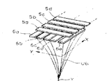
제3도는 본 발명장치에 사용되는 진동자의 한실시예를 나타내는 사시도.3 is a perspective view showing one embodiment of a vibrator used in the apparatus of the present invention.
제4도는 그 등가회로도.4 is an equivalent circuit diagram thereof.
제5도는 그 분활진동자의 실효체적을 설명하는 모식도(模式圖).5 is a schematic diagram explaining the effective volume of the divided vibrator.
제6도는 및 제7도는 진동자의 구동방법의 한실시예를 나타내는 원리도 및 요부사시도.6 and 7 are principle diagrams and main parts perspective views showing an embodiment of a method of driving a vibrator.
제8도는 진동자의 구동방법의 다른실시예를 나타내는 원리도.8 is a principle diagram showing another embodiment of the driving method of the vibrator.
제9도 및 제10도는 진동자의 구동방법의 한실시예의 회로 및 타이밍차아트.9 and 10 are circuit and timing difference arts of one embodiment of a method of driving a vibrator.
본 발명은 전자스캔(Scan)방식의 초음파프로우브(탐침)를 구비한 초음파 진단장치에 관한 것이다.The present invention relates to an ultrasonic diagnostic apparatus having an ultrasonic probe (probe) of an electronic scan method.
종래의 초음파 진단장치에 사용되는 전자스캔방식의 초음파프로우브는 제1도에서 보는 바와같이, 진동자재료 (예를들면, 압전소자) 1을 협지한 양면에 구동전극(2) 및 접지전극(3)이 형성된 진동자를 구비하고 있다. 이 구동전극(2)이 길이방향(X축 방향)에 따라 배치된 복수개의 분할전극에 의하여 구성된 개개의 분할전극에는 각각, 리이드선(2a)에 접속되고, 다른쪽의 접지전극(3)은 1장의 판상체(단일 플레이트)에 의하여 구성되고 1줄의 리이드선(3a)이 접속되어 있다. 여기에서, 각 분할전극과 접지전극으로 협지된 체적부분(압전소자의 각부분)은 개개의 진동자로서 기능을 하게되고, 제2도와 같은 등가회로로 표시된다.As shown in FIG. 1, the electronic scan type ultrasonic probe used in the conventional ultrasonic diagnostic apparatus includes a driving electrode 2 and a
이와 같은 구조의 진동자를 구비한 초음파 프로우브에 의하면, 분할진동자의 각각을 순차적으로 절환, 구동시키므로서, 또는 복수의 진동자를 몇개의 조로 구성하여, 동시구동한후 1개씩 간격을 두고 구동시키므로서 초음파비임의 촛점(focus)이나 진동자의 실효구경을 제어하게되고, 이에 따라 발사되는 초음파비임의 방향을 변경시키기도하고, 이동시킬 수도 있게 된다.According to the ultrasonic probe having a vibrator having such a structure, each of the divided vibrators is sequentially switched and driven, or a plurality of vibrators are configured in a plurality of pairs, and are driven at intervals one by one after simultaneous driving. The focus of the ultrasonic beam or the effective diameter of the vibrator is controlled, and thus the direction of the ultrasonic beam emitted can be changed or moved.
그러나, 상기 초음파프로우브에 사용되는 진동자에 의하며, 구동전극이 X축방향으로 복수개로 분할된 구조이기 때문에, X축 방향의 초음파 비임의 방향성(또는 특성)제어는 가능하지만, 진동자의 짧은 방향(Y축방향)에 대한 제어는 불가능하므로 여러가지 문제점이 발생하였다. 즉, 통상적으로 진동자의 구경이 작아지면 초음파비임의 지향성이 약화하므로 X축 방향만이 아니고, Y축방향에 있어서도 어느정도의 폭을 지니는 진동자를 사용해야하나, 이것을 위해 발사되는 초음파비임의 축방향의 지향성이 나빠져서, 필연적으로 얻어지는 에코우신호의 분해능이 저하되면서 불선명한 초음 파화상이 되고마는 일이많다. 이 경우에 Y축방향의 지향성의 개선을 도모하기 위하여 음향렌즈를 사용하는 방법이 있으나, 취급상의 불편이 있고, 부품수가 증가하는 등의 문제가 있었다. 한편, 공지사실로서, 구동전극을 X, Y측 양방향으로 분할하고 (이른바 매트릭스상으로 형성), 초음파비임의 X, Y측 양쪽방향의 지향성을 개선하려 해보았으나 이 경우에는 구동전극을 매트릭스상으로 배치하는 것이 가공기술적으로 곤란하다는 점, 또는 각 칩마다에 리이드선을 접속하기 때문에 배선수가 증대하는 등의 결점이 있어, 현실적으로 불가능했다.However, since the drive electrodes are divided into plural in the X-axis direction by the vibrator used in the ultrasonic probe, the directional (or characteristic) control of the ultrasonic beam in the X-axis direction is possible, but the short direction of the vibrator ( The control of the Y-axis direction) is impossible, causing various problems. That is, in general, when the diameter of the vibrator decreases, the directivity of the ultrasonic beam is weakened. Therefore, not only the X-axis direction but also a vibrator having a certain width in the Y-axis direction should be used. This worsens, and the resolution of the echo signal obtained inevitably decreases, often resulting in an unclear ultrasonic image. In this case, there is a method of using an acoustic lens to improve the directivity in the Y-axis direction, but there are problems such as inconvenience in handling and an increase in the number of parts. On the other hand, as a known fact, the driving electrodes were divided into both X and Y sides (so-called matrix formation), and an attempt was made to improve the directivity of both the X and Y sides of the ultrasonic beam. Arrangement is difficult in terms of processing technology, or there is a drawback in that the number of wirings is increased because the lead wires are connected to each chip.
따라서, 본 발명은 상기 결점을 고려하여 연구된 것으로서, 간단한 구조로 X, Y축 양방향의 송수신의 지향성의 개선을 할 수 있는 초음파프로우브를 구비한 초음파진단장치를 제공하는 것을 목적으로 하는 것이다. 이하 실시예를 따라, 본 발명을 구체적으로 설명한다.Accordingly, an object of the present invention is to provide an ultrasonic diagnostic apparatus having an ultrasonic probe capable of improving the directivity of transmission and reception in both X and Y axes in a simple structure. According to the following Examples, the present invention will be described in detail.
제3도는 본 발명의 초음파 진단장치에 사용되는 초음파프로우브의 진동자에 대한 한실시예를 나타내는 사시도인바, 이 진동자는 진동자재료(압전소자)(4)과, 이 압전소자를 협지하도록 배치형성된 구동전극(5) 및 접지전극(6)에 의하여 구성되어 있다. 여기에서, 구동전극(5)은 종래장치와 같이 X측방향에 따라 대략, 같은 간격으로 배열된 복수개(예를들면, 64개)의 분할전극(5a)-(5n)에 의하여 구성되고, 각 전극에는 리이드선(7)이 접속되어 있으나, 접지전극(6)은 종래와는 달리, Y측방향 (구동전극의 길이 방향에 직교되는 방향)에 따라 배열된 복수개(예를들면, 5개)의 분할적극(6a)-(6e)에 의하여 구성되고, 각 분할전극에는 각각 리이드선(8)이 접속되어 있다. 이와같은 구조의 진동자는 제4도에서 보는 바와같이 등가회로로서 표시된다. 즉, 각 분할구동전극(5a)-(5n)을 횡촉에 따라 배열한 경우, 각 전극에 압전소자(4)를 현저한 상태로 각분할 접지전극(6a)-(6e)이 배열결합된다.3 is a perspective view showing an embodiment of a vibrator of an ultrasonic probe used in the ultrasonic diagnostic apparatus of the present invention, the vibrator being a drive arranged to sandwich the vibrator material (piezoelectric element) 4 and the piezoelectric element. The
이와같은 구조의 진동자이면, 예를들어, 제5도와 같이 1개의 분할 구동전극(5c)과 분할접지전극(6c)에 전압을 인가했을때, 양전극에 의하여 협지된 공유부분(체적부분) S가 유효하게 진동자로서 작동하게 된다. 따라서, 각 분할전극에 개별적으로 또는 동시에 전압을 인가하므로서 진동자의 실효면적(진동자구경)을 임의로 제어할 수 있게 된다. 즉, 종래와 같이 구동전극에 적당히 전압을 인가하므로서 초음파비임의 X축 방향의 지향성을 제어할 수 있는 동시에, 접지전극에 적당히 전압을 인가하므로서 초음파비임 Y의 축방향의 지향성을 제어할 수 있는바, 양전극의 상호적구동(X 및 Y축에 대한)에 의하여 초음파비임의 특성(방향성)을 쉽게 개선할 수가 있다. 이 경우에, 각 분할전극은 방형(方形)상의 판재를 등간격으로 배열형성한 것으로서, 종래와 같이 미세칩상전극을 매트릭스상으로 배열한 경우와 비교해볼때 가공기술적으로도, 조립시에 있어서도 작업이 용이하고, 충분히 실현 가능한 것이다.In the vibrator having such a structure, for example, when a voltage is applied to one of the divided
이하, 송신시의 초음파비임의 지향성의 개선수법에 대한 한실시예의 대하여 제6도 및 제7도를 참조하여 설명한다. 각 분할진동자를 지연구동하므로서 발사되는 초음파비임을 집속시켜서 비임의 방해분해능을 개선하는 촛점법은 공지의 것이다. 제6도는 Y축방향에 대하여 이 촛점법을 적용한 것으로서, Y축방향으로 배열된 상기와 같은 분할진동자(S1)-(S5)를 적합하게 시간적으로 달리한 펄스(P1)-(P5)에 의하여 구동시키므로서 초음파비임 UB의 Y축방향의 지향성을 개선하는 것이다. 따라서, Y축방향의 비임의 집속구동과 X축방향의 비임의 집속구동을 동시에 실시하면, 제7도에 보는 바와같이 초음파비임 UB를 촛점 X에 접속하는 역 3각추상으로 할 수가 있고, 발사초음파 비임의 지향성의 현저한 개선이 도모된다.Hereinafter, an embodiment of the method for improving the directivity of the ultrasonic beam during transmission will be described with reference to FIGS. 6 and 7. FIG. The focusing method of focusing the ultrasonic beam emitted by delaying each split oscillator to improve the interference resolution of the beam is known. FIG. 6 shows the application of this focusing method in the Y-axis direction, in which the pulses P 1 )-(P appropriately different in time from the divided oscillators S 1- (S 5 ) arranged in the Y-axis direction. 5 ) to improve the directivity of the ultrasonic beam UB in the Y-axis direction. Therefore, if the focusing drive of the beam in the Y-axis direction and the focusing drive of the beam in the X-axis direction are performed at the same time, as shown in FIG. 7, the inverted triangular abstraction connecting the ultrasonic beam UB to the focus X can be made. A marked improvement in the directivity of the ultrasound beam is achieved.
이밖에, 각 분할진동자를 1개 간격으로 몰려놓고 차례로 구동해서 직선적으로 스캔하는 라이너(linear) 전자주사법, 또는 순차적으로 지연구동함으로서 비임을 소정각도의 섹터(Sector)상으로 주사시키는 섹터 주사법등의 수법을 Y축방향에도 채용할 수가 있고, 발신 초음파비임의 특성의 개선을 도모할수가 있다.In addition, a linear electron scanning method in which each divided vibrator is grouped at one interval and driven in sequence to scan linearly, or a sector scanning method in which a beam is scanned onto a sector at a predetermined angle by delayed driving in sequence The technique can be adopted also in the Y-axis direction, and the characteristics of the outgoing ultrasonic beam can be improved.
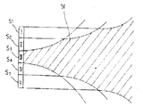
상기 설명은 발신시 초음파비임의 주향성의 개선에 대하여 설명한 것이나, 에코우(echo)원에 부딪쳐서 돌아오는 초음파에코우신호를 수신하는 경우에도 동일하게 적용된다. 제8도는 에코우원의 거리에 따라 진동자의 실현면적을 변화시키므로서 해칭(hatching)부 W와 같이 수신시의 지향성의 개선을 도모할 경우를 설명하기 위한 원리도로서, 이 도면에서 표시하는 바와같이, 5개의 진동자(S1)-(S5)를 배열한 경우, 근거리 에코우는 중앙의 진동자(S5)에 의해 수신하고, 중거리 에코우는 중간분의 3개의 진동자(S2)-(S4)에 의해 수신하고, 원거리 에코우는 전체의 진동자(S1)-(S5)로 수신하므로서 수신시의 지향성의 개선을 도모할 수가 있다. 따라서, 상기와 같이 Y축 방향으로 분할 배치된 5개의 접지전극을 사용하므로서 Y축방향의 수신지향성의 개선을 쉽게할 수가 있는 것이다.The above description is directed to the improvement of the directivity of the ultrasonic beam at the time of transmission, but the same applies to the case of receiving the ultrasonic echo signal that comes back by hitting the echo source. FIG. 8 is a principle diagram for explaining a case in which the directivity at the time of reception, such as a hatching part W, is to be improved by changing the realization area of the vibrator according to the distance of the echo circle, as shown in this figure. In the case of arranging five vibrators (S 1 )-(S 5 ), the near echo is received by the central vibrator (S 5 ), and the mid-distance echoes are three vibrators (S 2 )-(S 4) ), And the far echo is received by the entire vibrators S 1- (S 5 ), whereby the directivity at the time of reception can be improved. Therefore, the improvement of the reception directivity in the Y-axis direction can be easily achieved by using five ground electrodes dividedly arranged in the Y-axis direction as described above.
이하, 상시 진동자를 사용해서 수신시의 초음파에코우의 지향성의 개선을 도모하는 방법의 한실시예를 제9도 및 제10도를 참조해서 설명한다. 각 분할구동전극(5a)-(5n)는 긱각, 스위치(SW1)-(SW2)의 개재에 의해 절환스위치(SWA)에 공통적으로 접속되고, 각 분할접지전극(6a)-(6e)중 중앙의 접지전극(6c)은 직접 접지되고, 다른 접지전극(6a), (6b), (6e)은 각각, 스위치(SWa), (SWb), (SWc), (SWd)의 개재에 의해 공통으로 접지되고 있다. 상기 절환스위치(SWA)의 한쪽의 단자(a)는 발신기(10)에, 다른쪽 단자(b)는 수신기(11)에 각각 접속되어 있다. 각 스위치(SW1)-(SWn), (SWa)-(SWd), (SWA)는 각각 제어회로(12)로 부터의 제어신회에 의하여 구동되도록 되어 있다.Hereinafter, an embodiment of a method of improving the directivity of the ultrasonic echo at the time of reception using a constant oscillator will be described with reference to FIGS. 9 and 10. Each of the divided driving
이하, 제10도의 타이밍차아트를 참조하여 동작을 설명한다. 우선, 송신의 경우는 절환스위치(SWA)를 단자(a)쪽에 접속하는 동시에 구동전극측의 스위치(SW1)를 폐쇄하고, 접지전측의 스위치(SWa)-(SWd)를 폐쇄하여 소망의 초음파비임을 발신한다(시각 t1).The operation will be described below with reference to the timing difference art in FIG. First, in the case of transmission, the switching switch SWA is connected to the terminal a, and at the same time, the switch SW 1 on the drive electrode side is closed, and the switches SWa-SWd on the front ground side are closed, and the desired ultrasonic wave is closed. Send the beam (time t 1 ).
다음에, 절환스위치(SWA)를 (b)측으로 절환하는 동시에, 접지전극의 스위치(SWa)-(SWd)를 전부폐쇄하여 중앙부의 진동자에 의하여 근거리 에코우를 수신한다(시각 t2). 그리고, 접지전극전극측의 스위치(SWb) 및 (SWc)를 폐쇄하고 중간부의 3개의 진동자부분으로 중거리 에코우를 수신한다(시각 t3). 마지막으로, 모든 접지전극측의 스위치(SWa)-(SWd)를 폐쇄하고, 5개의 진동자에 의하여 원거리 에코우를 수신한다(시각 t4). 이와 같이 하여 1사이클의 동작이 종료된다. 다음은, 구동전극측의 스위치(SW1)를 개방하는 동시에, 2단째의 스위치(SW2)를 폐쇄하여 상기와 같은 구동을 실시하여 이하 차례로 조작을 한다. 이와 같이하여 초음파비임이 X방향으로 차례로 스캔되고, 수신되어서 소망의 진단이 이루어진다. 이때, 상기와 같이 수신시의 Y축 방향의 초음파의 지향성이 개선되는 것이다.Next, the switching switch SWA is switched to the (b) side, and the switches SWa-SWd of the ground electrode are all closed to receive the near-echo rain by the vibrator at the center (time t 2 ). Then, the switches SWb and SWc on the ground electrode electrode side are closed, and the middle distance echo is received by the three vibrator portions of the middle portion (time t 3 ). Finally, the switches SWa-SWd on all ground electrode sides are closed, and the far echo is received by the five vibrators (time t 4 ). In this way, the operation of one cycle is terminated. Next, the switch SW 1 on the drive electrode side is opened, the switch SW 2 on the second stage is closed, and the above-described driving is performed to operate in the following order. In this way, the ultrasonic beams are sequentially scanned in the X-direction, and received, and a desired diagnosis is made. At this time, the directivity of the ultrasonic wave in the Y-axis direction at the time of reception is improved as described above.
이상의 동작설명은 Y축방향의 초음파의 지향성의 개선에 대한 것이였으나, X축 방향의 지향성에 대해서는 종래와 동일한 수법에 의하여 개선이 도모되는 것은 물론이다. 따라서, 이소음파 프로우브을 사용한 초음파구동에 의하면 X, Y축 양방향성을 개선할 수 있는 것이다.The above description of the operation is directed to the improvement of the directivity of the ultrasonic waves in the Y-axis direction, but of course the improvement in the directivity in the X-axis direction can be achieved by the same method as in the prior art. Therefore, according to the ultrasonic drive using the acoustic wave probe, the bidirectional X and Y axes can be improved.
본 발명은 상기 실시예에 한정되지 않고, 각분할전극 수의 증감, 또는 구동방법을 여러가지 조합하므로서 지향성을 더욱 개선하도록 해도 되고, 진동자를 구성하는 불할전극은 분할구동 전극에 대하여 직교하는 방향으로 분할접지전극을 배열하는 경우에 한정되지 아니하고, 양자가 어느정도의 각도를 유지하여 배열(즉, 교차만 되어 있지 아니하면)되도록 해도된다.The present invention is not limited to the above embodiment, and the directivity may be further improved by increasing or decreasing the number of divided electrodes or by combining various driving methods, and the non-electrode constituting the vibrator is divided in a direction orthogonal to the divided driving electrodes. The present invention is not limited to the case of arranging the ground electrodes, but may be arranged so as to be arranged at a certain angle (that is, not intersecting only).
이상 설명한 본 발명에 의하면, 각 분할전극을 서로 교차하는 방향으로 배열하는 것만의 간단한 구성의 진동자를 사용하여 X, Y축 양방향의 초음파 송수신시의 지향성의 개선을 실시할 수가 있는 초음파 프로우브를 구비한 초음파 진단장치를 제공할 수가 있다.According to the present invention described above, an ultrasonic probe is provided which can improve the directivity in transmitting / receiving ultrasonic waves in both X and Y axes by using a vibrator having a simple configuration only by arranging the divided electrodes in a direction crossing each other. One ultrasonic diagnostic apparatus can be provided.
Claims (1)
Applications Claiming Priority (2)
| Application Number | Priority Date | Filing Date | Title |
|---|---|---|---|
| JP6159280A JPS56158648A (en) | 1980-05-09 | 1980-05-09 | Ultrasonic diagnostic apparatus |
| JP61592 | 1980-05-09 |
Publications (2)
| Publication Number | Publication Date |
|---|---|
| KR830004830A KR830004830A (en) | 1983-07-20 |
| KR850000056B1 true KR850000056B1 (en) | 1985-02-15 |
Family
ID=13175565
Family Applications (1)
| Application Number | Title | Priority Date | Filing Date |
|---|---|---|---|
| KR1019810001482A KR850000056B1 (en) | 1980-05-09 | 1981-04-29 | Ultrasonic scanning apparatus |
Country Status (4)
| Country | Link |
|---|---|
| US (1) | US4448075A (en) |
| JP (1) | JPS56158648A (en) |
| KR (1) | KR850000056B1 (en) |
| GB (1) | GB2075797B (en) |
Families Citing this family (26)
| Publication number | Priority date | Publication date | Assignee | Title |
|---|---|---|---|---|
| DE3373739D1 (en) * | 1982-07-21 | 1987-10-22 | Technicare Corp | Selectable focus ultrasonic transducers for diagnostic imaging |
| JPS605136A (en) * | 1983-06-24 | 1985-01-11 | 株式会社日立製作所 | Ultrasonic tomographic apparatus |
| JPS60158844A (en) * | 1984-01-27 | 1985-08-20 | 横河メディカルシステム株式会社 | Ultrasonic diagnostic apparatus |
| DE3409815A1 (en) * | 1984-03-16 | 1985-09-26 | Siemens AG, 1000 Berlin und 8000 München | Porous sintered oxide ceramic and transducers produced therefrom |
| US4640291A (en) * | 1985-06-27 | 1987-02-03 | North American Philips Corporation | Bi-plane phased array for ultrasound medical imaging |
| DE3525179A1 (en) * | 1985-07-15 | 1987-01-22 | Siemens Ag | METHOD AND DEVICE FOR ULTRASONIC SCANNING OF AN OBJECT |
| JPH0783518B2 (en) * | 1985-10-09 | 1995-09-06 | 株式会社日立製作所 | Ultrasonic probe |
| GB8617567D0 (en) * | 1986-07-18 | 1986-08-28 | Szilard J | Ultrasonic imaging apparatus |
| US4945915A (en) * | 1987-02-20 | 1990-08-07 | Olympus Optical Co., Ltd. | Ultrasonic diagnosis apparatus |
| US4881409A (en) * | 1988-06-13 | 1989-11-21 | Westinghouse Electric Corp. | Multi-point wall thickness gage |
| JPH02217000A (en) * | 1989-02-16 | 1990-08-29 | Hitachi Ltd | Ultrasonic wave probe |
| US5466336A (en) * | 1992-02-10 | 1995-11-14 | Cpg Holdings Inc. | Process for making a paper based product employing a polymeric latex binder |
| DE4405504B4 (en) * | 1994-02-21 | 2008-10-16 | Siemens Ag | Method and apparatus for imaging an object with a 2-D ultrasound array |
| US5671746A (en) * | 1996-07-29 | 1997-09-30 | Acuson Corporation | Elevation steerable ultrasound transducer array |
| CA2406684A1 (en) * | 2001-10-05 | 2003-04-05 | Queen's University At Kingston | Ultrasound transducer array |
| JP2003235839A (en) * | 2002-02-18 | 2003-08-26 | Matsushita Electric Ind Co Ltd | Ultrasonic diagnostic system |
| US6637268B1 (en) * | 2002-05-20 | 2003-10-28 | Kohji Toda | Vibration displacement sensing system |
| US6640631B1 (en) * | 2002-05-20 | 2003-11-04 | Kohji Toda | System and measuring sound velocity in material |
| JP2004230033A (en) * | 2003-01-31 | 2004-08-19 | Toshiba Corp | Ultrasonic search unit repolarizing apparatus, ultrasonic probe, and ultrasonograph |
| US7828736B2 (en) * | 2004-01-27 | 2010-11-09 | Fujinon Corporation | Electronic scan type ultrasound diagnostic instrument |
| JP4486127B2 (en) * | 2004-05-17 | 2010-06-23 | ヒューマンスキャン・カンパニー・リミテッド | Ultrasonic probe and manufacturing method thereof |
| JP4621452B2 (en) * | 2004-08-20 | 2011-01-26 | 富士フイルム株式会社 | Ultrasound endoscope and ultrasound endoscope apparatus |
| KR101336246B1 (en) * | 2012-04-23 | 2013-12-03 | 삼성전자주식회사 | Ultrasonic transducer, ultrasonic probe, and ultrasound image diagnosis apparatus |
| US11061124B2 (en) | 2016-10-21 | 2021-07-13 | The Governors Of The University Of Alberta | System and method for ultrasound imaging |
| US11150344B2 (en) | 2018-01-26 | 2021-10-19 | Roger Zemp | 3D imaging using a bias-sensitive crossed-electrode array |
| US11448621B2 (en) | 2020-03-30 | 2022-09-20 | Olympus NDT Canada Inc. | Ultrasound probe with row-column addressed array |
Family Cites Families (14)
| Publication number | Priority date | Publication date | Assignee | Title |
|---|---|---|---|---|
| GB772083A (en) * | 1952-09-20 | 1957-04-10 | Nat Res Dev | Improvements in and relating to the transmission of ultrasonic vibrations |
| GB1023549A (en) * | 1962-10-26 | 1966-03-23 | Nat Res Dev | Apparatus comprising piezo-electric elements and circuits used in conjunction therewith |
| GB1244551A (en) * | 1969-02-28 | 1971-09-02 | British Aircraft Corp Ltd | Improvements relating to acoustic detector arrays |
| JPS5237951B2 (en) * | 1973-01-18 | 1977-09-26 | ||
| FR2252580B1 (en) * | 1973-11-22 | 1980-02-22 | Realisations Ultrasoniques Sa | |
| FR2334953A1 (en) * | 1975-12-11 | 1977-07-08 | Labo Electronique Physique | ULTRASONIC ANALYSIS SYSTEM AND ITS APPLICATION TO ECHOGRAPHY |
| US4131023A (en) * | 1976-03-04 | 1978-12-26 | Rca Corporation | Pulse-echo ultrasonic-imaging display system |
| DE2713087A1 (en) * | 1976-04-05 | 1977-10-13 | Varian Associates | PROCESS FOR IMPROVING THE RESOLUTION OF ULTRASONIC IMAGES AND DEVICE FOR CARRYING OUT THE PROCESS |
| JPS52131676A (en) * | 1976-04-27 | 1977-11-04 | Tokyo Shibaura Electric Co | Probe for ultrasonic diagnostic device |
| JPS53142071A (en) * | 1977-05-17 | 1978-12-11 | Aloka Co Ltd | Ultrasonic diagnosing device |
| JPS547786A (en) * | 1977-06-17 | 1979-01-20 | Aloka Co Ltd | Ultrasonic wave receiver |
| US4307613A (en) * | 1979-06-14 | 1981-12-29 | University Of Connecticut | Electronically focused ultrasonic transmitter |
| FR2460489A1 (en) * | 1979-07-04 | 1981-01-23 | Labo Electronique Physique | CIRCUIT FOR PROCESSING RECEPTION SIGNALS OF A ULTRA-SOUND TRANSDUCER MOSAIC USED IN B-TYPE ECHOGRAPHY |
| DE3010210A1 (en) * | 1980-03-17 | 1981-09-24 | Siemens AG, 1000 Berlin und 8000 München | ULTRASONIC ARRAY |
-
1980
- 1980-05-09 JP JP6159280A patent/JPS56158648A/en active Granted
-
1981
- 1981-04-29 KR KR1019810001482A patent/KR850000056B1/en active
- 1981-05-06 US US06/260,992 patent/US4448075A/en not_active Expired - Lifetime
- 1981-05-07 GB GB8113910A patent/GB2075797B/en not_active Expired
Also Published As
| Publication number | Publication date |
|---|---|
| GB2075797A (en) | 1981-11-18 |
| JPS6346693B2 (en) | 1988-09-16 |
| US4448075A (en) | 1984-05-15 |
| JPS56158648A (en) | 1981-12-07 |
| KR830004830A (en) | 1983-07-20 |
| GB2075797B (en) | 1984-07-04 |
Similar Documents
| Publication | Publication Date | Title |
|---|---|---|
| KR850000056B1 (en) | Ultrasonic scanning apparatus | |
| US4550606A (en) | Ultrasonic transducer array with controlled excitation pattern | |
| US5115810A (en) | Ultrasonic transducer array | |
| US4319489A (en) | Ultrasonic diagnostic method and apparatus | |
| US4542653A (en) | Apparatus and method for beamforming in an ultrasonic transducer array | |
| US4692654A (en) | Ultrasonic transducer of monolithic array type | |
| US4831601A (en) | Apparatus for transmitting and receiving ultrasonic signals | |
| US4440025A (en) | Arc scan transducer array having a diverging lens | |
| JP4172841B2 (en) | Ultrasound imaging system, method of operating ultrasound imaging system and multiplexer motherboard | |
| US4870867A (en) | Crossed linear arrays for ultrasonic medical imaging | |
| KR910000233B1 (en) | Ultrasonic diagnostic apparatus | |
| JPS625337A (en) | Phased array for medical ultrasonic imaging | |
| US4644214A (en) | Probe for electronic scanning type ultrasonic diagnostic apparatus | |
| JPS5941730B2 (en) | Biological examination device using ultrasound scanning | |
| EP0396761B1 (en) | Ultrasonic wave inspecting apparatus | |
| US4200858A (en) | Acoustic wave scanning apparatus | |
| JPH0886777A (en) | Ultrasonic wave probe device | |
| JP4365158B2 (en) | 2D array ultrasonic probe | |
| JP2004286680A (en) | Ultrasonic transceiver | |
| JPH0113546B2 (en) | ||
| JPS6227600B2 (en) | ||
| JPH0242498B2 (en) | ||
| US3132276A (en) | Electroluminescent display device | |
| JPH0862196A (en) | Ultrasonic diagnostic apparatus | |
| JPS6258738B2 (en) |