KR820000756B1 - Rotor blade - Google Patents
Rotor blade Download PDFInfo
- Publication number
- KR820000756B1 KR820000756B1 KR7803921A KR780003921A KR820000756B1 KR 820000756 B1 KR820000756 B1 KR 820000756B1 KR 7803921 A KR7803921 A KR 7803921A KR 780003921 A KR780003921 A KR 780003921A KR 820000756 B1 KR820000756 B1 KR 820000756B1
- Authority
- KR
- South Korea
- Prior art keywords
- radius
- blade
- disk
- root
- groove
- Prior art date
Links
- 238000005452 bending Methods 0.000 description 7
- 239000000463 material Substances 0.000 description 5
- 230000003247 decreasing effect Effects 0.000 description 2
- 241001659652 Discus catskillensis Species 0.000 description 1
- 230000000712 assembly Effects 0.000 description 1
- 238000000429 assembly Methods 0.000 description 1
- 238000002485 combustion reaction Methods 0.000 description 1
- 230000006835 compression Effects 0.000 description 1
- 238000007906 compression Methods 0.000 description 1
- 238000005516 engineering process Methods 0.000 description 1
- 239000000446 fuel Substances 0.000 description 1
- 230000000149 penetrating effect Effects 0.000 description 1
- 230000001629 suppression Effects 0.000 description 1
Images


Classifications
-
- F—MECHANICAL ENGINEERING; LIGHTING; HEATING; WEAPONS; BLASTING
- F01—MACHINES OR ENGINES IN GENERAL; ENGINE PLANTS IN GENERAL; STEAM ENGINES
- F01D—NON-POSITIVE DISPLACEMENT MACHINES OR ENGINES, e.g. STEAM TURBINES
- F01D5/00—Blades; Blade-carrying members; Heating, heat-insulating, cooling or antivibration means on the blades or the members
- F01D5/30—Fixing blades to rotors; Blade roots ; Blade spacers
- F01D5/32—Locking, e.g. by final locking blades or keys
-
- F—MECHANICAL ENGINEERING; LIGHTING; HEATING; WEAPONS; BLASTING
- F01—MACHINES OR ENGINES IN GENERAL; ENGINE PLANTS IN GENERAL; STEAM ENGINES
- F01D—NON-POSITIVE DISPLACEMENT MACHINES OR ENGINES, e.g. STEAM TURBINES
- F01D5/00—Blades; Blade-carrying members; Heating, heat-insulating, cooling or antivibration means on the blades or the members
- F01D5/30—Fixing blades to rotors; Blade roots ; Blade spacers
- F01D5/3007—Fixing blades to rotors; Blade roots ; Blade spacers of axial insertion type
- F01D5/3015—Fixing blades to rotors; Blade roots ; Blade spacers of axial insertion type with side plates
-
- F—MECHANICAL ENGINEERING; LIGHTING; HEATING; WEAPONS; BLASTING
- F01—MACHINES OR ENGINES IN GENERAL; ENGINE PLANTS IN GENERAL; STEAM ENGINES
- F01D—NON-POSITIVE DISPLACEMENT MACHINES OR ENGINES, e.g. STEAM TURBINES
- F01D5/00—Blades; Blade-carrying members; Heating, heat-insulating, cooling or antivibration means on the blades or the members
- F01D5/30—Fixing blades to rotors; Blade roots ; Blade spacers
- F01D5/3007—Fixing blades to rotors; Blade roots ; Blade spacers of axial insertion type
Abstract
Description
제1도는 로우터 블레이드 조립체의 일부의 개략도.1 is a schematic representation of a portion of a rotor blade assembly.
제2도는 본 발명에 따른 형상을 가진 제1도의 블레이드의 근부 부착구조의 일부를 보인 확대도.Figure 2 is an enlarged view showing a part of the root attachment structure of the blade of Figure 1 having a shape according to the present invention.
제3도는 종래 기술의 근부 부착구조의 제2도와 유사한 확대도.3 is an enlarged view similar to FIG. 2 of the root attachment structure of the prior art.
제4도는 본 발명의 이중 곡률반경을 보인 “톱니뿌리형”부착구조의 일부를 보인 확대도.4 is an enlarged view showing a part of the "toothed root" attachment structure showing the double curvature radius of the present invention.
본 발명은 회전기계류, 특히 가스터어빈 엔진의 터어빈 휘일 조립체의 로우터 블레이드에 관한 것이다.The present invention relates to rotor blades of rotary machinery, in particular turbine wheel assemblies of a gas turbine engine.
근래 가스터어빈엔진은 본 발명의 개념이 적용되는 제1급의 회전기계류를 포함한다. 가스터어빈 엔진에서, 구동 매개가스는 엔진이 압축실에서 압축되고, 연료가 구동매개 가스에 혼합되고 연소되어 유통 매개체에 에너지를 부여하는 연소실로 흐른다. 그리하여 높은 에너지 매개체가 터어빈실로 흐르고 여기에서 그 에너지의 일부가 추출되어 엔진 압축기를 구동시키도록 공급된다.Recently, a gas turbine engine includes a first class rotary machinery to which the concept of the present invention is applied. In the gas turbine engine, the driving medium gas flows into the combustion chamber where the engine is compressed in the compression chamber, the fuel is mixed with the driving medium gas and burned to energize the flow medium. Thus, a high energy medium flows into the turbine chamber, where part of that energy is extracted and supplied to drive the engine compressor.
터어빈은 다수의 교대적인 열들의 로우터 블레이드 및 고정 베인(vane)으로 구성고되, 고정 베인의 각열은 로우터 블레이드의 하류측열에 선택된 유입각도로 구동 매개 가스를 직접 향하게 하고, 다시 로우터 블레이드는 그 매개가스로부터 엔진 압축기를 구동시키기 위한 에너지를 추출한다. 각 열의 로우터 블레이드는 원형 원반체의외 주면에 착설되어 있다. 로우터 블레이드와 지지원반체의 조합체는 휘일조립체로 알려져 있다. 가스터어빈 엔진이 작동하는 동안 터어빈 휘일의 회전속도는 7500rpm 이상인 것이 보통이다.The turbine consists of a plurality of alternating rows of rotor blades and stationary vanes, each row of stationary vanes directs the driving medium gas at a selected inlet angle downstream of the rotor blades, and again the rotor blades Energy is extracted from the engine for driving the compressor. The rotor blades in each row are mounted on the outer main surface of the circular disk. The combination of rotor blade and support disc is known as wheel assembly. While the gas turbine engine is in operation, the rotation speed of the turbine wheel is usually more than 7500 rpm.
터어빈 휘일 조립체의 각 블레이드는, 원반체의 동일형상의 부작용 슬로트(slot)와 계합하는 근부(root section)가 형성되어 있다. 복잡한 근부의 가하학적인 구조는 원반체로 부터 각 블레이드로의 구심력억제 하중을 전달할 수 있도록 창안되어 있다. 광범위하게 사용되는 하나의 그러한 기하학적인 구조로서 “토비 뿌리형”(fir tree)부착 구조가 있다. 이러한 부착구조가 제1도에 도시되어 있으며, 본 발명은 이러한 형태에 관한 것으로 설명된다.Each blade of the turbine wheel assembly has a root section engaging with a side-effect slot of the same shape of the disk. The complex geometry of the root is designed to transfer centripetal force suppression loads from the disk to each blade. One such geometric structure that is widely used is the "fir tree" attachment structure. This attachment structure is shown in FIG. 1, and the invention is described as being in this form.
로우터블레이드와 원반체의 수명을 제한하는 하나의 요인은 각 부품이 제조되는 재료의 낮은 주기 피로 수명(low cycle fatigue life)이다. 각 작동주기는 각 부품에 일정한 수준의 영향을 가하며, 이러한 것이 반복된 후는 최종적으로는 그 부품들이 약화되어 파열될 것이다. 매우 낮은 응력수준에서, 파열이 일어나기 전의 싸이클수는 거의 무한하다., 그러나, 매우 높은 응력 수준에서는 싸이클수가 매우 엄격히 제한된다.One factor that limits the life of rotorblades and discs is the low cycle fatigue life of the material from which each part is made. Each cycle of operation exerts a certain level of influence on each component, and after this is repeated, the components will eventually weaken and burst. At very low stress levels, the number of cycles before rupture occurs is almost infinite, but at very high stress levels the number of cycles is very strictly limited.
각 부품의 피로수명은 그의 LCF수명으로 불린다.The fatigue life of each part is called its LCF life.
가장 최근의 엔진에서 실시되고 있는 블레이드 부착기술의 현재수준은 “톱니뿌리형”부착구조의 일부를 나타낸 제3도(종래기술)에서 보인 바와 같다. 블레이드 근부의 치(齒)는 원반체 부착의 슬로트에 형성된 상응하는 홈에 계합하도록 연장되어 있다. 원반체의 각 홈은 단일 반경으로 형성되어 있으며, 유사하게 원반체슬로트의 치도 블레이드 근부의 상응하는 홈들에 계합하도록 연장되어 있다. 근부의 각 홈도 단일반경으로 형성되어 있다. 본 발명의 개념은 이후 설명되는 바와 같은 종래기술의 개념과는 상이하다.The current level of blade attachment technology implemented in the most recent engines is as shown in Figure 3 (prior art) showing some of the "toothed" attachment structures. The teeth of the blade root extend to engage corresponding grooves formed in the slot of disc attachment. Each groove of the disk is formed with a single radius and similarly extends to engage corresponding grooves of the dent blade edge of the disk slot. Each groove in the root portion is also formed with a single radius. The concept of the present invention is different from the concept of the prior art as described later.
본 발명의 주 목적은, 터어빈 블레이드 근부와 그들의 상응하는 원반체 부착 슬로트에 적절한 낮은 주기 피로수명을 제공하기 위한 것이다. 부수적인 목적은 각 근부와 그의 상응하는 부착슬로트의 길이를 최소화하는데 있다. 또한 조합된 굽힘응력과 전단응력의 수준이 감소되었으며, 특별한 목적은 굽힘하중 및 전단하중에 의해 외주면 재질에 장력이 부여되는 지역에서 윤곽의 반경을 증가시킬 수 있게 하는데 있다.The main object of the present invention is to provide a low cycle fatigue life suitable for turbine blade roots and their corresponding disk attachment slots. A secondary purpose is to minimize the length of each root and its corresponding attachment slot. In addition, the levels of combined bending and shear stresses have been reduced, and a special purpose is to increase the radius of the contour in areas where tension is applied to the outer circumferential material by bending and shear loads.
본 발명에 따라, 로우터 블레이드의 근부는 지지원반체의 부착슬로트에 형성된 홈들에 계합하도록 연장한 다수의 치를 가지고 있으며, 각 홈은 반경방향의 측지역의제 반1경부와 반경방향 제2반경부를 가지는 형상으로 형성되고, 제1 반경부가 제2반경부보다 크게되어 있다.According to the invention, the root portion of the rotor blade has a number of teeth extending to engage grooves formed in the attachment slot of the support disk, each groove having a first half diameter and a second radial radius in the radial side region. It is formed in the shape which has a part, and a 1st radius part is larger than a 2nd radius part.
유사하게, 로우터 원반체의 부착 슬로트는 로우터 블레이드의 근부에 형성된 홈들과 계합하도록 연장한 수개의 치를 가지며, 여기에서 각홈은 반경방향 내측 지역의 제1 반경부와 반경방향 외측지역의 제2 반경부를 가지는 형상으로 형성되고, 그 제1 반경부가 제2 반경부보다 크게 되어 있다.Similarly, the attachment slot of the rotor disc has several teeth extending to engage the grooves formed in the vicinity of the rotor blade, wherein each groove has a first radius in the radially inner region and a second radius in the radially outer region. The branch is formed into a shape, and the first radius portion is larger than the second radius portion.
본 발명의 주 특징은 원반체 홈들과 로우터 블레이드의 홈들의 복합적인 형상구조이다. 각 홈은 제1 반경부와 제2반경부를 갖는 형상으로 형성되고, 그 제1 반경부가 제3 반경부보다 크며, 굽힘하중과 전단하중에 의해 블레이드가 큰 장력하게 있게 하도록 작용하는 홈의 지역에 형성되어 있다. 제2 반경부는 굽힘하중과 전단하중이 반대로 작용하는 근부의 지역에 형성된다.The main feature of the present invention is a complex geometry of disk grooves and grooves of the rotor blade. Each groove is formed in a shape having a first radius portion and a second radius portion, the first radius portion of which is larger than the third radius portion, and in an area of the groove that acts to cause the blade to be greatly tensioned by bending and shear loads. Formed. The second radius is formed in the region of the root where the bending and shear loads act oppositely.
이러한 본 발명의 한 실시형태의 주요잇점은 동일한 근부 깊이에 낮은주기 피로수명(LCF)을 부여하는 것이다.The main advantage of one embodiment of this invention is to impart low cycle fatigue life (LCF) to the same root depth.
본 발명에 따른 제1 반경부를 증가시키고 제2 반경부를 감소시킴에 의해, 그에 다른 근부깊이의 증가없이 최대응력을 줄일수 있게 된다. 다른 실시 형태에서, 원반체 하중이 낮은 주기 피로수명이 감소없이도 감소될 수 있고, 근부깊이의 감소에 의해 원반체 림(rin)의 재료의 양이 감소된다.By increasing the first radius and decreasing the second radius according to the invention, it is possible to reduce the maximum stress without increasing the other depth of the root. In another embodiment, the disk load can be reduced without reducing the low cycle fatigue life, and the amount of material of the disk rin is reduced by decreasing the root depth.
본 발명을 첨부된 예시도면에 의하여 보다 상세히 설명하면 다음과 같다.When described in more detail by the accompanying drawings illustrating the present invention.
터어빈 휘일조립체(10)의 일부분이 제1도에 도시되었다. 이 터어빈휘일 조립체는 로우터 원반체(12)와 이로부터 반경방향 외측으로 연장한 다수의 로우터 블레이드(14)로 구성되며, 각 블레이드는 근부(16)와 에어포일 부분(19)로 구성되고, 각 근부는 “톱니뿌리형”으로 되어 있다. 각 블레이드의 근부는 원반체의 외주면에 형성되고 근부와 같은 형태의 슬로트(20)에 계합하여, 각원반체의 슬로트는 블레이드와 원반체사이에 근부공동부(cavity)(22)를 형성하도록 블레이드 근부의 하측으로 연장되어 있다. 그리고 적어도 하나의 측판914)이 블레이드를 원반체슬로트내에 고정시키기 위하여 원반체에 부착되어 있고, 근부공동부를 관통하는 다수의 리벳트(26)가 각 측판을 원반체에 고정한다.A portion of the turbine wheel assembly 10 is shown in FIG. This turbine wheel assembly consists of a rotor disc 12 and a plurality of
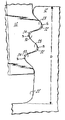
“톱니뿌리형”부착구조가 제2도 및 제4도에 보다 상세히 도시되어 있다. 블레이드이 근부(16)에는 원반체와 계합하기 위하여 연장한 다수의 치(28)가 형성되어 있고, 이와 유사하게 원반체의 부착슬르트에도 블레이드의 근부와 계합하기 위하여 연장한 수개의 치(30)가 형성되어 있다. 즉 각 블레이드의 치는 원반체 슬로트에 형성된 홈(32)에 수용되고, 각 원반체의 치는 블레이드에 형성된 홈(34)에 수용된다. 각원반체 홈은 그의 상측부, 즉 반경방향 외측지역(36)에는 제1반경부(R1)이, 그리고 하측부, 즉 반경방향 내측지역(30)에는 제2반경부(R2)이 형성된 형상으로 되어있다. 또한 각 블레이드 홈은 그의 하측부, 즉 반경 방향내측지역(40)에 제1반경부(R1)이 그리고 상측부, 즉 반경방향 외측지역(42)에 제2 반경부(R2)가 형성된 형상으로 되어 있다. 여기에서, 반경 R1은 반경 R2보다 크다. 제4도는 원반체 홈과 블레이드 홈의 형상을 형성하는 반경 R1과 R2의 관계를 나타낸다.A "toothed root" attachment structure is shown in greater detail in FIGS. 2 and 4. A plurality of
터어빈휘일 조립체의 회전중, 원심력이 블레이드를 원반체로부터 반경 방향의 측으로 향하게 하고 구심억제력은 원반체의 “톱니뿌리형”부착구조를 통하여 각 블레이드에 부여된다. 따라서 블레이드의 치와 원반체의 치에 전단응력과 굽힘응력이 조합되어 부여된다. 원반체 홈(32)의 상측지역(36)과 블레이드 홈(34)의 하측지역(40)에서 전단 및 굽힘응력이 부가된다. 원반체 홈의 하측지역(38)과 블레이드 홈의 상측지역(42)에서는 전단응력과 굽힘응력이 서로 반대로 된다. 따라서, 조합된 최대응력은 지역(38)(40)에서, 특히휘이 S에까이에서 일어나가게 되는 것이다.During rotation of the turbine wheel assembly, centrifugal force directs the blades radially from the disk and centripetal restraint is imparted to each blade through the disk's "toothed" attachment structure. Therefore, the shear stress and bending stress are imparted to the teeth of the blade and the teeth of the disk. Shear and bending stresses are applied in the upper region 36 of the disk groove 32 and in the lower region 40 of the
본 발명의 “톱니뿌리형”부착구조가 제2도 및 제3도에서 종래기술의 “톱니뿌리형”부착구조와 비교하여 도시되어 있다. 블레이드의 외주와 원반체의 외주에서의 최대응력은 가장 응력이 집중되는 지역 S에서 거의 동일하게 나타난다. 그러므로, 본 발명의 실시형태에서는 근부깊이(D)의 감소가 가능하게 된다. 근부의 깊이의 감소는 원반체 홈(32)와 블레이드홈(34)를 형성하는 복합적인 반경을 이용함으로서 가능하게 될수 있다. 그 홈들은 놓은 응력이 집중적으로 가하여지는 지역 S에 큰 반경부(R1)이 형성되고 응력을 적게받는 지역에 작은 반경부(R2)가 형성되었다.The "toothed" attachment structure of the present invention is shown in FIGS. 2 and 3 as compared to the "toothed" attachment structure of the prior art. The maximum stresses on the outer periphery of the blade and the outer periphery of the disc appear almost the same in the area S where the most stress is concentrated. Therefore, in the embodiment of the present invention, the root depth D can be reduced. Reduction of the depth of the root can be made possible by using a complex radius that forms the disk groove 32 and the
원반체의 림(rin)의 응력을 받지않는 부분의 재료의 양은 근부의 깊이(D)에직접적으로 비례한다. 따라서 근부깊이의 감소에 의해 가벼운 원반체 구성이 가능하게 되고, 부수적으로 근부깊이의 감소에 의해, 비교적 직경이 작은 원반체상에 다수의 블레이드를 필요로하는 예에서 원반치에 많은 수의 블레이드를 설치할 수 있게된다. 블레이드를 원반체의 외주면에 적절한 재료를 유지하면서 보다 근접되게 착설할 수도 있다.The amount of material in the unstressed portion of the disk rin is directly proportional to the depth D of the root. Therefore, a light disk can be constructed by reducing the depth of the root, and consequently, by reducing the depth of the root, a large number of blades are installed on the disk in an example requiring a large number of blades on a relatively small disk. Will be. The blade may be placed closer to the outer circumferential surface of the disk while maintaining a suitable material.
다른 실시형태에서, 본 발명은 동등한 블레이드 깊이(D)에서의 최대 응력을 줄일 수도 있다. 이러한 실싱형태에서는, 반경 R1이 제2도에서 보인것보다 더 크게되고, 반면에 반경 R2는 일정하게 유지된다.In another embodiment, the present invention may reduce the maximum stress at equivalent blade depth D. In this type of seal, the radius R 1 becomes larger than shown in FIG. 2 , while the radius R 2 remains constant.
Claims (1)
Applications Claiming Priority (2)
| Application Number | Priority Date | Filing Date | Title |
|---|---|---|---|
| US05/864,948 US4191509A (en) | 1977-12-27 | 1977-12-27 | Rotor blade attachment |
| US864.948 | 1977-12-27 |
Publications (1)
| Publication Number | Publication Date |
|---|---|
| KR820000756B1 true KR820000756B1 (en) | 1982-05-04 |
Family
ID=25344390
Family Applications (1)
| Application Number | Title | Priority Date | Filing Date |
|---|---|---|---|
| KR7803921A KR820000756B1 (en) | 1977-12-27 | 1978-12-26 | Rotor blade |
Country Status (19)
| Country | Link |
|---|---|
| US (1) | US4191509A (en) |
| JP (1) | JPS5496618A (en) |
| KR (1) | KR820000756B1 (en) |
| AU (1) | AU520295B2 (en) |
| BE (1) | BE873014A (en) |
| BR (1) | BR7808517A (en) |
| CA (1) | CA1112184A (en) |
| CH (1) | CH640916A5 (en) |
| DE (1) | DE2853856A1 (en) |
| DK (1) | DK581078A (en) |
| FR (1) | FR2413541B1 (en) |
| GB (1) | GB2011552B (en) |
| IL (2) | IL56125A (en) |
| IN (1) | IN149724B (en) |
| IT (1) | IT1101094B (en) |
| NO (1) | NO155159C (en) |
| PL (1) | PL123377B1 (en) |
| SE (1) | SE443184B (en) |
| YU (1) | YU39689B (en) |
Families Citing this family (47)
| Publication number | Priority date | Publication date | Assignee | Title |
|---|---|---|---|---|
| US4477222A (en) * | 1982-09-30 | 1984-10-16 | The United States Of America As Represented By The Secretary Of The Air Force | Mounting construction for turbine vane assembly |
| JPS63501372A (en) * | 1985-07-30 | 1988-05-26 | ウエスチングハウス・エレクトリック・コ−ポレ−ション | Method for determining the shape of side-entry turbine blades that can be designed using scale models |
| US4692976A (en) * | 1985-07-30 | 1987-09-15 | Westinghouse Electric Corp. | Method of making scalable side entry turbine blade roots |
| US4824328A (en) * | 1987-05-22 | 1989-04-25 | Westinghouse Electric Corp. | Turbine blade attachment |
| GB2238581B (en) * | 1989-11-30 | 1994-01-12 | Rolls Royce Plc | Improved attachment of a gas turbine engine blade to a turbine rotor disc |
| US5100292A (en) * | 1990-03-19 | 1992-03-31 | General Electric Company | Gas turbine engine blade |
| US5152669A (en) * | 1990-06-26 | 1992-10-06 | Westinghouse Electric Corp. | Turbomachine blade fastening |
| US5141401A (en) * | 1990-09-27 | 1992-08-25 | General Electric Company | Stress-relieved rotor blade attachment slot |
| US5147180A (en) * | 1991-03-21 | 1992-09-15 | Westinghouse Electric Corp. | Optimized blade root profile for steam turbine blades |
| US5176500A (en) * | 1992-03-24 | 1993-01-05 | Westinghouse Electric Corp. | Two-lug side-entry turbine blade attachment |
| DE4432999C2 (en) * | 1994-09-16 | 1998-07-30 | Mtu Muenchen Gmbh | Impeller of a turbomachine, in particular an axially flow-through turbine of a gas turbine engine |
| DE4435268A1 (en) * | 1994-10-01 | 1996-04-04 | Abb Management Ag | Bladed rotor of a turbo machine |
| US5494408A (en) * | 1994-10-12 | 1996-02-27 | General Electric Co. | Bucket to wheel dovetail design for turbine rotors |
| DE4436727A1 (en) * | 1994-10-14 | 1996-04-18 | Abb Management Ag | Drum rotor for an axially flowed turbo machine |
| US5531569A (en) * | 1994-12-08 | 1996-07-02 | General Electric Company | Bucket to wheel dovetail design for turbine rotors |
| DE19516694C2 (en) * | 1995-05-06 | 2001-06-28 | Mtu Aero Engines Gmbh | Device for fixing blades to the impeller, in particular a turbine of a gas turbine engine |
| DE19603388C1 (en) * | 1996-01-31 | 1997-07-24 | Mtu Muenchen Gmbh | Device for fixing the blades on the impeller, in particular a turbine of a gas turbine engine, by riveting |
| DE19619316C2 (en) * | 1996-05-14 | 2002-07-18 | Voith Siemens Hydro Power | Impeller for a free jet turbine |
| JP2000512707A (en) * | 1996-06-21 | 2000-09-26 | シーメンス アクチエンゲゼルシヤフト | Rotor of turbine machine having blades mountable in groove and rotor blades |
| AUPO729997A0 (en) * | 1997-06-11 | 1997-07-03 | Cleland, Glen Irving | Engine disabling apparatus |
| DE19728085A1 (en) * | 1997-07-02 | 1999-01-07 | Asea Brown Boveri | Joint connection between two joining partners and their use |
| US6033185A (en) * | 1998-09-28 | 2000-03-07 | General Electric Company | Stress relieved dovetail |
| GB2345943B (en) * | 1998-12-04 | 2003-07-09 | Glenn Bruce Sinclair | Precision crowning of blade attachments in gas turbines |
| US6139277A (en) * | 1998-12-22 | 2000-10-31 | Air Concepts, Inc. | Motorized fan |
| US6592330B2 (en) * | 2001-08-30 | 2003-07-15 | General Electric Company | Method and apparatus for non-parallel turbine dovetail-faces |
| US6773234B2 (en) | 2002-10-18 | 2004-08-10 | General Electric Company | Methods and apparatus for facilitating preventing failure of gas turbine engine blades |
| US8079817B2 (en) * | 2004-02-10 | 2011-12-20 | General Electric Company | Advanced firtree and broach slot forms for turbine stage 3 buckets and rotor wheels |
| US7905709B2 (en) * | 2004-02-10 | 2011-03-15 | General Electric Company | Advanced firtree and broach slot forms for turbine stage 1 and 2 buckets and rotor wheels |
| EP1584792A1 (en) * | 2004-04-08 | 2005-10-12 | Siemens Aktiengesellschaft | Blade attachment for a compressor or a turbine |
| DE102004051116A1 (en) * | 2004-10-20 | 2006-04-27 | Mtu Aero Engines Gmbh | Rotor of a turbomachine, in particular gas turbine rotor |
| US7261518B2 (en) * | 2005-03-24 | 2007-08-28 | Siemens Demag Delaval Turbomachinery, Inc. | Locking arrangement for radial entry turbine blades |
| JP4869616B2 (en) * | 2005-04-01 | 2012-02-08 | 株式会社日立製作所 | Steam turbine blade, steam turbine rotor, steam turbine using the same, and power plant |
| US7156612B2 (en) * | 2005-04-05 | 2007-01-02 | Pratt & Whitney Canada Corp. | Spigot arrangement for a split impeller |
| US7387494B2 (en) * | 2005-04-28 | 2008-06-17 | General Electric Company | Finger dovetail attachment between a turbine rotor wheel and bucket for stress reduction |
| US7690896B2 (en) * | 2005-05-27 | 2010-04-06 | United Technologies Corporation | Gas turbine disk slots and gas turbine engine using same |
| EP2019913A4 (en) * | 2006-05-12 | 2011-06-01 | Gen Electric | BLADE/DISK DOVETAIL BACKCUT FOR BLADE/DISK STRESS REDUCTION (6FA+e, STAGE 2) |
| US8047797B2 (en) * | 2007-07-16 | 2011-11-01 | Nuovo Pignone Holdings, S.P.A. | Steam turbine and rotating blade |
| US8038404B2 (en) * | 2007-07-16 | 2011-10-18 | Nuovo Pignone Holdings, S.P.A. | Steam turbine and rotating blade |
| US8047796B2 (en) * | 2007-11-16 | 2011-11-01 | General Electric Company | Dovetail attachment for use with turbine assemblies and methods of assembling turbine assemblies |
| EP2546465A1 (en) * | 2011-07-14 | 2013-01-16 | Siemens Aktiengesellschaft | Blade root, corresponding blade, rotor disc, and turbomachine assembly |
| US9359905B2 (en) | 2012-02-27 | 2016-06-07 | Solar Turbines Incorporated | Turbine engine rotor blade groove |
| US9546556B2 (en) * | 2012-09-26 | 2017-01-17 | United Technologies Corporation | Turbine blade root profile |
| GB201416505D0 (en) * | 2014-09-18 | 2014-11-05 | Rolls Royce Plc | Gas turbine engine |
| CN104832220A (en) * | 2014-12-31 | 2015-08-12 | 东方电气集团东方汽轮机有限公司 | Blade root and wheel groove structure of turbine moving blade |
| EP3093441B1 (en) | 2015-05-12 | 2019-07-10 | Ansaldo Energia Switzerland AG | Turbo engine rotor comprising a blade-shaft connection, and blade for said rotor |
| WO2016195689A1 (en) * | 2015-06-04 | 2016-12-08 | Siemens Energy, Inc. | Attachment system for turbine engine airfoil |
| CN109145335B (en) * | 2017-06-28 | 2023-05-30 | 中国航发贵阳发动机设计研究所 | Method for improving low cycle fatigue life of wheel disc through pre-rotation |
Family Cites Families (5)
| Publication number | Priority date | Publication date | Assignee | Title |
|---|---|---|---|---|
| US2429215A (en) * | 1943-01-16 | 1947-10-21 | Jarvis C Marble | Turbine blade |
| GB677142A (en) * | 1949-08-24 | 1952-08-13 | Power Jets Res & Dev Ltd | Improved mounting for turbine and like blades |
| DE950557C (en) * | 1952-12-23 | 1956-10-11 | Svenska Turbinfab Ab | Fir tree base for blades of axial turbines or compressors |
| US3891351A (en) * | 1974-03-25 | 1975-06-24 | Theodore J Norbut | Turbine disc |
| US4029436A (en) * | 1975-06-17 | 1977-06-14 | United Technologies Corporation | Blade root feather seal |
-
1977
- 1977-12-27 US US05/864,948 patent/US4191509A/en not_active Expired - Lifetime
-
1978
- 1978-12-05 IL IL56125A patent/IL56125A/en unknown
- 1978-12-06 CA CA317,455A patent/CA1112184A/en not_active Expired
- 1978-12-08 PL PL1978211564A patent/PL123377B1/en unknown
- 1978-12-13 DE DE19782853856 patent/DE2853856A1/en active Granted
- 1978-12-14 AU AU42519/78A patent/AU520295B2/en not_active Expired
- 1978-12-15 YU YU2954/78A patent/YU39689B/en unknown
- 1978-12-18 SE SE7812961A patent/SE443184B/en not_active IP Right Cessation
- 1978-12-18 IN IN1351/CAL/78A patent/IN149724B/en unknown
- 1978-12-19 CH CH1286978A patent/CH640916A5/en not_active IP Right Cessation
- 1978-12-19 GB GB7849010A patent/GB2011552B/en not_active Expired
- 1978-12-22 IT IT31226/78A patent/IT1101094B/en active
- 1978-12-22 NO NO784349A patent/NO155159C/en unknown
- 1978-12-22 BE BE192511A patent/BE873014A/en not_active IP Right Cessation
- 1978-12-22 DK DK581078A patent/DK581078A/en not_active Application Discontinuation
- 1978-12-25 JP JP16461378A patent/JPS5496618A/en active Granted
- 1978-12-26 KR KR7803921A patent/KR820000756B1/en active
- 1978-12-26 BR BR7808517A patent/BR7808517A/en unknown
- 1978-12-27 FR FR7837057A patent/FR2413541B1/en not_active Expired
-
1981
- 1981-05-08 IL IL62817A patent/IL62817A0/en unknown
Also Published As
| Publication number | Publication date |
|---|---|
| YU295478A (en) | 1982-06-30 |
| DE2853856A1 (en) | 1979-07-05 |
| PL211564A1 (en) | 1979-07-30 |
| IN149724B (en) | 1982-03-27 |
| IT7831226A0 (en) | 1978-12-22 |
| US4191509A (en) | 1980-03-04 |
| PL123377B1 (en) | 1982-10-30 |
| JPS5496618A (en) | 1979-07-31 |
| BR7808517A (en) | 1979-08-21 |
| IL62817A0 (en) | 1981-07-31 |
| SE7812961L (en) | 1979-06-28 |
| IT1101094B (en) | 1985-09-28 |
| AU4251978A (en) | 1979-07-05 |
| NO155159B (en) | 1986-11-10 |
| GB2011552A (en) | 1979-07-11 |
| BE873014A (en) | 1979-04-17 |
| CA1112184A (en) | 1981-11-10 |
| YU39689B (en) | 1985-03-20 |
| IL56125A (en) | 1982-02-28 |
| SE443184B (en) | 1986-02-17 |
| FR2413541B1 (en) | 1986-04-18 |
| FR2413541A1 (en) | 1979-07-27 |
| GB2011552B (en) | 1982-03-31 |
| NO784349L (en) | 1979-06-28 |
| JPS6146644B2 (en) | 1986-10-15 |
| NO155159C (en) | 1987-02-18 |
| CH640916A5 (en) | 1984-01-31 |
| DK581078A (en) | 1979-06-28 |
| AU520295B2 (en) | 1982-01-21 |
| DE2853856C2 (en) | 1987-04-02 |
Similar Documents
| Publication | Publication Date | Title |
|---|---|---|
| KR820000756B1 (en) | Rotor blade | |
| EP0431766B1 (en) | Improved attachment of a gas turbine engine blade to a turbine rotor disc | |
| JP4017794B2 (en) | Stress relaxation dovetail | |
| US5232344A (en) | Internally damped blades | |
| US3918842A (en) | Blade assembly for a fluid flow machine | |
| US9822647B2 (en) | High chord bucket with dual part span shrouds and curved dovetail | |
| EP0799972B1 (en) | A root attachment for a Turbomachine blade | |
| US3734646A (en) | Blade fastening means | |
| US5183389A (en) | Anti-rock blade tang | |
| JP2000337294A (en) | Moving blade support structure from which stress is removed | |
| US3047268A (en) | Blade retention device | |
| EP3380704B1 (en) | Flexible damper for turbine blades | |
| US5284421A (en) | Rotor blade with platform support and damper positioning means | |
| KR20010062682A (en) | Blade attachment configuration | |
| EP3880936B1 (en) | Bladed rotor system and method of servicing a bladed rotor system | |
| US4685863A (en) | Turbine rotor assembly | |
| EP2275644A2 (en) | Turbine bucket tip cover comprising a plurality of depressions | |
| US4688992A (en) | Blade platform | |
| US3198485A (en) | Turbine blade lock | |
| JP2017519143A (en) | Rotationally symmetric components for turbine engine rotors, and associated turbine engine rotors, turbine engine modules, and turbine engines | |
| US10876411B2 (en) | Non-axisymmetric end wall contouring with forward mid-passage peak | |
| GB2127104A (en) | Sealing means for a turbine rotor blade in a gas turbine engine | |
| GB2344383A (en) | Damping vibration of gas turbine engine blades | |
| US5104290A (en) | Bladed rotor with axially extending radially re-entrant features | |
| NO760674L (en) |