KR20240046536A - Quenching device and continuous annealing equipment, and quenching method, manufacturing method of steel sheet, and manufacturing method of plated steel sheet - Google Patents
Quenching device and continuous annealing equipment, and quenching method, manufacturing method of steel sheet, and manufacturing method of plated steel sheet Download PDFInfo
- Publication number
- KR20240046536A KR20240046536A KR1020247007663A KR20247007663A KR20240046536A KR 20240046536 A KR20240046536 A KR 20240046536A KR 1020247007663 A KR1020247007663 A KR 1020247007663A KR 20247007663 A KR20247007663 A KR 20247007663A KR 20240046536 A KR20240046536 A KR 20240046536A
- Authority
- KR
- South Korea
- Prior art keywords
- metal plate
- flow rate
- quenching
- cooling
- shape
- Prior art date
Links
- 238000010791 quenching Methods 0.000 title claims abstract description 148
- 230000000171 quenching effect Effects 0.000 title claims abstract description 147
- 229910000831 Steel Inorganic materials 0.000 title claims abstract description 44
- 239000010959 steel Substances 0.000 title claims abstract description 44
- 238000004519 manufacturing process Methods 0.000 title claims abstract description 25
- 238000000034 method Methods 0.000 title claims abstract description 24
- 238000000137 annealing Methods 0.000 title claims abstract description 13
- 239000002184 metal Substances 0.000 claims abstract description 194
- 229910052751 metal Inorganic materials 0.000 claims abstract description 194
- 238000001816 cooling Methods 0.000 claims abstract description 75
- 239000012809 cooling fluid Substances 0.000 claims abstract description 43
- 239000007921 spray Substances 0.000 claims abstract description 7
- 238000005452 bending Methods 0.000 claims description 71
- 238000007747 plating Methods 0.000 claims description 5
- 238000005246 galvanizing Methods 0.000 claims description 4
- 238000005507 spraying Methods 0.000 claims description 4
- 239000003507 refrigerant Substances 0.000 description 17
- 239000000463 material Substances 0.000 description 16
- XLYOFNOQVPJJNP-UHFFFAOYSA-N water Substances O XLYOFNOQVPJJNP-UHFFFAOYSA-N 0.000 description 16
- 238000005259 measurement Methods 0.000 description 9
- 229910001335 Galvanized steel Inorganic materials 0.000 description 6
- 239000002826 coolant Substances 0.000 description 6
- 239000008397 galvanized steel Substances 0.000 description 6
- 230000000052 comparative effect Effects 0.000 description 5
- 239000010960 cold rolled steel Substances 0.000 description 4
- 238000010586 diagram Methods 0.000 description 4
- 238000002347 injection Methods 0.000 description 4
- 239000007924 injection Substances 0.000 description 4
- 238000005516 engineering process Methods 0.000 description 3
- 239000000498 cooling water Substances 0.000 description 2
- 230000007547 defect Effects 0.000 description 2
- 239000012530 fluid Substances 0.000 description 2
- 230000006870 function Effects 0.000 description 2
- 229910052748 manganese Inorganic materials 0.000 description 2
- 239000000203 mixture Substances 0.000 description 2
- 230000009466 transformation Effects 0.000 description 2
- 238000009835 boiling Methods 0.000 description 1
- 229910052804 chromium Inorganic materials 0.000 description 1
- 229910052802 copper Inorganic materials 0.000 description 1
- 238000009826 distribution Methods 0.000 description 1
- 230000000694 effects Effects 0.000 description 1
- 238000010438 heat treatment Methods 0.000 description 1
- 238000010191 image analysis Methods 0.000 description 1
- 238000007654 immersion Methods 0.000 description 1
- 239000012535 impurity Substances 0.000 description 1
- 238000010801 machine learning Methods 0.000 description 1
- 229910000734 martensite Inorganic materials 0.000 description 1
- 229910052750 molybdenum Inorganic materials 0.000 description 1
- 229910052759 nickel Inorganic materials 0.000 description 1
- 229910052758 niobium Inorganic materials 0.000 description 1
- 230000000630 rising effect Effects 0.000 description 1
- 238000005096 rolling process Methods 0.000 description 1
- 230000001629 suppression Effects 0.000 description 1
- 238000004381 surface treatment Methods 0.000 description 1
- 229910052719 titanium Inorganic materials 0.000 description 1
- 229910052720 vanadium Inorganic materials 0.000 description 1
Images
Classifications
-
- C—CHEMISTRY; METALLURGY
- C21—METALLURGY OF IRON
- C21D—MODIFYING THE PHYSICAL STRUCTURE OF FERROUS METALS; GENERAL DEVICES FOR HEAT TREATMENT OF FERROUS OR NON-FERROUS METALS OR ALLOYS; MAKING METAL MALLEABLE, e.g. BY DECARBURISATION OR TEMPERING
- C21D1/00—General methods or devices for heat treatment, e.g. annealing, hardening, quenching or tempering
- C21D1/62—Quenching devices
- C21D1/63—Quenching devices for bath quenching
-
- C—CHEMISTRY; METALLURGY
- C21—METALLURGY OF IRON
- C21D—MODIFYING THE PHYSICAL STRUCTURE OF FERROUS METALS; GENERAL DEVICES FOR HEAT TREATMENT OF FERROUS OR NON-FERROUS METALS OR ALLOYS; MAKING METAL MALLEABLE, e.g. BY DECARBURISATION OR TEMPERING
- C21D1/00—General methods or devices for heat treatment, e.g. annealing, hardening, quenching or tempering
- C21D1/18—Hardening; Quenching with or without subsequent tempering
-
- C—CHEMISTRY; METALLURGY
- C21—METALLURGY OF IRON
- C21D—MODIFYING THE PHYSICAL STRUCTURE OF FERROUS METALS; GENERAL DEVICES FOR HEAT TREATMENT OF FERROUS OR NON-FERROUS METALS OR ALLOYS; MAKING METAL MALLEABLE, e.g. BY DECARBURISATION OR TEMPERING
- C21D1/00—General methods or devices for heat treatment, e.g. annealing, hardening, quenching or tempering
- C21D1/62—Quenching devices
- C21D1/667—Quenching devices for spray quenching
-
- C—CHEMISTRY; METALLURGY
- C21—METALLURGY OF IRON
- C21D—MODIFYING THE PHYSICAL STRUCTURE OF FERROUS METALS; GENERAL DEVICES FOR HEAT TREATMENT OF FERROUS OR NON-FERROUS METALS OR ALLOYS; MAKING METAL MALLEABLE, e.g. BY DECARBURISATION OR TEMPERING
- C21D9/00—Heat treatment, e.g. annealing, hardening, quenching or tempering, adapted for particular articles; Furnaces therefor
- C21D9/52—Heat treatment, e.g. annealing, hardening, quenching or tempering, adapted for particular articles; Furnaces therefor for wires; for strips ; for rods of unlimited length
- C21D9/54—Furnaces for treating strips or wire
- C21D9/56—Continuous furnaces for strip or wire
- C21D9/573—Continuous furnaces for strip or wire with cooling
-
- C—CHEMISTRY; METALLURGY
- C23—COATING METALLIC MATERIAL; COATING MATERIAL WITH METALLIC MATERIAL; CHEMICAL SURFACE TREATMENT; DIFFUSION TREATMENT OF METALLIC MATERIAL; COATING BY VACUUM EVAPORATION, BY SPUTTERING, BY ION IMPLANTATION OR BY CHEMICAL VAPOUR DEPOSITION, IN GENERAL; INHIBITING CORROSION OF METALLIC MATERIAL OR INCRUSTATION IN GENERAL
- C23C—COATING METALLIC MATERIAL; COATING MATERIAL WITH METALLIC MATERIAL; SURFACE TREATMENT OF METALLIC MATERIAL BY DIFFUSION INTO THE SURFACE, BY CHEMICAL CONVERSION OR SUBSTITUTION; COATING BY VACUUM EVAPORATION, BY SPUTTERING, BY ION IMPLANTATION OR BY CHEMICAL VAPOUR DEPOSITION, IN GENERAL
- C23C2/00—Hot-dipping or immersion processes for applying the coating material in the molten state without affecting the shape; Apparatus therefor
- C23C2/04—Hot-dipping or immersion processes for applying the coating material in the molten state without affecting the shape; Apparatus therefor characterised by the coating material
- C23C2/06—Zinc or cadmium or alloys based thereon
-
- C—CHEMISTRY; METALLURGY
- C25—ELECTROLYTIC OR ELECTROPHORETIC PROCESSES; APPARATUS THEREFOR
- C25D—PROCESSES FOR THE ELECTROLYTIC OR ELECTROPHORETIC PRODUCTION OF COATINGS; ELECTROFORMING; APPARATUS THEREFOR
- C25D3/00—Electroplating: Baths therefor
- C25D3/02—Electroplating: Baths therefor from solutions
- C25D3/22—Electroplating: Baths therefor from solutions of zinc
-
- C—CHEMISTRY; METALLURGY
- C22—METALLURGY; FERROUS OR NON-FERROUS ALLOYS; TREATMENT OF ALLOYS OR NON-FERROUS METALS
- C22C—ALLOYS
- C22C38/00—Ferrous alloys, e.g. steel alloys
-
- C—CHEMISTRY; METALLURGY
- C22—METALLURGY; FERROUS OR NON-FERROUS ALLOYS; TREATMENT OF ALLOYS OR NON-FERROUS METALS
- C22C—ALLOYS
- C22C38/00—Ferrous alloys, e.g. steel alloys
- C22C38/60—Ferrous alloys, e.g. steel alloys containing lead, selenium, tellurium, or antimony, or more than 0.04% by weight of sulfur
Abstract
??칭 전의 금속판에 이미 휨이 있었던 경우에도, ??칭 후의 금속판의 휨을 억제할 수 있는 ??칭 장치 및 연속 어닐링 설비, 그리고 ??칭 방법, 강판의 제조 방법 및 도금 강판의 제조 방법을 제공하는 것을 목적으로 하는 것이다.
??칭 장치 (1) 는, 금속판 (S) 의 표면 및 이면에 냉각 유체를 분사하는 복수의 분출 노즐 (12) 을 구비하는 냉각 장치 (10) 와, ??칭 전의 금속판 (S) 의 형상에 기초하여, 분출 노즐 (12) 로부터 금속판 (S) 의 표면 및 이면에 분사하는 냉각 유체의 유량을 설정하는 유량 조정 장치 (30) 를 구비한다.A quenching device and continuous annealing facility that can suppress the warping of a metal sheet after quenching even when there is already warpage in the metal sheet before quenching, as well as a quenching method, a steel sheet manufacturing method, and a plated steel sheet manufacturing method. The purpose is to provide.
The quenching device 1 includes a cooling device 10 including a plurality of jet nozzles 12 that spray cooling fluid on the front and back surfaces of the metal plate S, and the shape of the metal plate S before quenching. Based on this, a flow rate adjustment device 30 is provided that sets the flow rate of the cooling fluid sprayed from the jet nozzle 12 onto the front and back surfaces of the metal plate S.
Description
본 발명은, 금속판을 연속적으로 통판하면서 ??칭을 실시하는 ??칭 장치 및 연속 어닐링 설비, 그리고 ??칭 방법, 강판의 제조 방법 및 도금 강판의 제조 방법에 관한 것이다.The present invention relates to a quenching device and continuous annealing equipment for performing quenching while continuously sheeting a metal plate, as well as a quenching method, a steel sheet manufacturing method, and a plated steel sheet manufacturing method.
강판을 비롯한 금속판의 제조에 있어서는, 금속판을 연속적으로 통판시키면서 어닐링을 실시하는 연속 어닐링 설비에 있어서, 금속판을 가열 후에 냉각하여, 상 변태를 촉진시키는 것 등에 의해, 재질을 만들어 낸다. 최근, 자동차 업계에서는 차체의 경량화와 충돌 안전성의 양립을 목적으로 하여, 박육화한 고장력 강판 (하이텐) 의 수요가 증가하고 있다.In the production of metal plates, including steel plates, materials are created by heating and then cooling the metal plates to promote phase transformation in a continuous annealing facility that performs annealing while continuously rolling the metal plates. Recently, in the automobile industry, demand for thinner high-strength steel sheets (HI-TEN) has been increasing for the purpose of achieving both lightweight car bodies and crash safety.
고장력 강판의 제조시에는, 강판을 급속히 냉각시키는 기술이 중요해진다. 예를 들어, 가장 빠르게 냉각시킬 수 있는 기술 중 하나가 워터 ??칭법이다. 워터 ??칭법에서는, 가열된 강판을 수중에 침지시킴과 동시에 수중 내에 설치된 ??치 노즐에 의해 냉각수를 강판에 분사함으로써, 강판의 ??칭이 행해진다. 강판의 ??칭시에는, 강판에 휨이나 파상 (波狀) 변형 등의 형상 불량이 발생한다는 문제가 있다.When manufacturing high-strength steel sheets, technology for rapidly cooling the steel sheets becomes important. For example, one of the fastest cooling technologies is water cooling. In the water quenching method, quenching of the steel sheet is performed by immersing the heated steel sheet in water and simultaneously spraying cooling water onto the steel sheet through a quench nozzle installed in the water. When forming a steel plate, there is a problem that shape defects such as bending and waviness deformation occur in the steel plate.
이러한 강판의 ??칭시에 있어서의 형상 불량을 방지하기 위해, 종래, 다양한 수법이 제안되어 있다 (예를 들면 특허문헌 1, 2 참조). 특허문헌 1 에는, 가열된 스트립을 수랭하는 침지수 중에, 냉각수 분사 노즐이 다단으로 설치되고, 또한, 각 노즐 헤더가 각각 스트립 진행 방향에 대하여 이간시켜 배치된 구조가 개시되어 있다. 이로써, 종래의 다단 슬릿 노즐에서 발생하였던 횡 흐름을 방지하고, 판폭 방향 냉각에 있어서의 균일성을 갖게 할 수 있다.In order to prevent shape defects when forming such steel sheets, various methods have been conventionally proposed (for example, see Patent Documents 1 and 2). Patent Document 1 discloses a structure in which cooling water spray nozzles are installed in multiple stages in immersion water for water cooling a heated strip, and each nozzle header is arranged to be spaced apart with respect to the strip travel direction. As a result, it is possible to prevent the lateral flow that occurred in the conventional multi-slit nozzle and provide uniformity in cooling in the sheet width direction.
또, 특허문헌 2 에서는, 연속 어닐링로 (爐) 에서의 ??칭시에 발생하는 금속판의 파상 변형을 억제하기 위해, ??칭 공정에 부가되는 강판의 장력을 바꿀 수 있는 장력 변경 수단으로서, 브라이들 롤을 ??칭부 전후에 형성하는 수법이 개시되어 있다.Additionally, in
그러나 특허문헌 1 에 개시된 방법에서는, ??칭 전의 금속판에 이미 휨이 있었던 경우에는, 형상 교정 효과가 불충분하다는 문제가 있다. 또한, 특허문헌 2 에 개시된 방법에서는, 고온의 금속판에 큰 장력을 가하기 때문에 금속판의 파단이 일어날 우려가 있다. 또, 고온의 금속판에 접촉하는 ??칭부 전의 브라이들 롤에는 큰 서멀 크라운이 발생하여, 브라이들 롤과 금속판이 폭 방향으로 불균일하게 접촉하고, 그 결과, 금속판에 좌굴이나 흠집이 발생하기 때문에, 금속판의 형상을 개선할 수 없다는 문제가 있다.However, in the method disclosed in Patent Document 1, there is a problem that the shape correction effect is insufficient when the metal plate before quenching is already warped. Additionally, in the method disclosed in
본 발명은 이러한 과제를 해결하기 위해 이루어진 것으로, ??칭 전의 금속판에 이미 휨이 있었던 경우에도, ??칭 후의 금속판의 휨을 억제할 수 있는 ??칭 장치 및 연속 어닐링 설비, 그리고 ??칭 방법, 강판의 제조 방법 및 도금 강판의 제조 방법을 제공하는 것을 목적으로 한다.The present invention was made to solve these problems, and provides a quenching device and continuous annealing equipment that can suppress the warping of a metal sheet after quenching even when the metal sheet before quenching already has warpage, and a quenching method. The purpose is to provide a method of manufacturing a steel sheet and a method of manufacturing a plated steel sheet.
[1] 금속판을 냉각하는 ??칭 장치로서, 상기 금속판의 표면 및 이면에 냉각 유체를 분사하는 복수의 분출 노즐을 구비하는 냉각 장치와, ??칭 전의 상기 금속판의 형상에 기초하여, 상기 분출 노즐로부터 상기 금속판의 표면 및 이면에 분사되는 냉각 유체의 유량을 설정하는 유량 조정 장치를 갖고, 상기 유량 조정 장치는, ??칭 전의 상기 금속판이 표면측으로 볼록한 휨 형상인 경우에는 상기 금속판의 표면측보다 이면측의 유량을 크게 설정하고, ??칭 전의 상기 금속판이 이면측으로 볼록한 휨 형상인 경우에는 상기 금속판의 이면측보다 표면측의 유량을 크게 설정하는, ??칭 장치.[1] A cooling device for cooling a metal plate, the cooling device comprising a plurality of jet nozzles for spraying cooling fluid on a front and back surfaces of the metal plate, and based on the shape of the metal plate before quenching, the jet It has a flow rate adjustment device that sets the flow rate of the cooling fluid sprayed from a nozzle on the front and back surfaces of the metal plate, and the flow rate adjustment device is configured to adjust the flow rate of the cooling fluid on the surface side of the metal plate when the metal plate before quenching has a curved shape that is convex toward the surface side. A quenching device in which the flow rate on the back side is set to be larger, and when the metal plate before quenching has a curved shape that is convex toward the back side, the flow rate on the front side is set to be larger than that on the back side of the metal plate.
[2] 상기 금속판의 형상은, ??칭 전의 상기 금속판의 형상을 측정하는 형상 측정 장치에 의해 측정되는, [1] 에 기재된 ??칭 장치.[2] The quenching device according to [1], wherein the shape of the metal plate is measured by a shape measuring device that measures the shape of the metal plate before quenching.
[3] 상기 형상 측정 장치는, 상기 금속판의 휨량을 측정하는 기능을 갖고, 상기 유량 조정 장치는, 상기 금속판의 휨량이 커질수록, 상기 금속판의 표면에 분사하는 냉각 유체의 유량과 이면에 분사하는 냉각 유체의 유량의 유량차를 크게 설정하는 [2] 에 기재된 ??칭 장치.[3] The shape measuring device has a function of measuring the amount of deflection of the metal plate, and the flow rate adjustment device adjusts the flow rate of the cooling fluid sprayed on the surface of the metal plate and the flow rate of the cooling fluid sprayed on the back side as the amount of deflection of the metal plate increases. A cooling device described in [2] that sets a large flow rate difference in the flow rate of the cooling fluid.
[4] 상기 금속판의 표면에 분사하는 냉각 유체의 유량과 이면에 분사하는 냉각 유체의 유량의 유량차는, 휨량을 d (mm) 로 했을 때, 20×d+200 (m3/hr) 미만인 [3] 에 기재된 ??칭 장치.[4] The flow rate difference between the flow rate of the cooling fluid sprayed on the surface of the metal plate and the flow rate of the cooling fluid sprayed on the back side is less than 20 × d + 200 (m 3 /hr) when the deflection amount is d (mm) [3] The quenching device described in .
[5] 상기 형상 측정 장치는, ??칭 전의 상기 금속판이 통과하는 형상 측정 롤로 이루어지고, 상기 형상 측정 장치와 상기 냉각 장치에 의한 냉각 개시점의 거리는 0.5 m 이상 2.0 m 이하인 [2] ∼ [4] 중 어느 하나에 기재된 ??칭 장치.[5] The shape measuring device consists of a shape measuring roll through which the metal plate before quenching passes, and the distance between the shape measuring device and the cooling start point by the cooling device is 0.5 m or more and 2.0 m or less [2] to [ 4] The quenching device described in any one of the above.
[6] [1] ∼ [5] 중 어느 하나에 기재된 ??칭 장치를 균열대의 출측에 구비하는 연속 어닐링 설비.[6] A continuous annealing facility equipped with the quenching device according to any one of [1] to [5] on the exit side of the crack zone.
[7] 복수의 분출 노즐로부터 금속판의 표면 및 이면에 냉각 유체를 분사하여 금속판을 냉각하는 ??칭 방법으로서, ??칭 전의 상기 금속판의 형상에 기초하여, 상기 분출 노즐로부터 상기 금속판의 표면 및 이면에 분사하는 냉각 유체의 유량을 설정할 때, 상기 금속판이 표면측으로 볼록한 휨 형상인 경우에는 상기 금속판의 표면측보다 이면측의 유량을 크게 하고, 상기 금속판이 이면측으로 볼록한 휨 형상인 경우에는 상기 금속판의 이면측보다 표면측의 유량을 크게 하는 ??칭 방법.[7] A quenching method in which a cooling fluid is sprayed onto the front and back surfaces of a metal plate from a plurality of jet nozzles to cool the metal sheet, based on the shape of the metal sheet before quenching, from the jet nozzles to the surface and back of the metal sheet. When setting the flow rate of the cooling fluid sprayed on the back side, if the metal plate has a curved shape that is convex toward the front side, the flow rate on the back side is set larger than the surface side of the metal plate. If the metal plate has a curved shape that is convex toward the back side, the flow rate on the back side is set to be larger. A method of increasing the flow rate on the surface side than on the back side.
[8] 상기 금속판의 형상 중, 상기 금속판의 휨량을 파악하고, 냉각 유체의 유량을 설정할 때, 상기 금속판의 휨량이 커질수록, 상기 금속판의 표면에 분사하는 냉각 유체의 유량과 이면에 분사하는 냉각 유체의 유량의 유량차를 크게 하는 [7] 에 기재된 ??칭 방법.[8] Among the shapes of the metal plate, when determining the amount of deflection of the metal plate and setting the flow rate of the cooling fluid, as the amount of deflection of the metal plate increases, the flow rate of the cooling fluid sprayed on the surface of the metal plate and the cooling sprayed on the back surface increase. The quenching method described in [7], which increases the flow rate difference in fluid flow rate.
[9] 상기 금속판의 표면에 분사하는 냉각 유체의 유량과 이면에 분사하는 냉각 유체의 유량의 유량차는, 휨량을 d (mm) 로 했을 때, 20×d+200 (m3/hr) 미만인 [8] 에 기재된 ??칭 방법.[9] The flow rate difference between the flow rate of the cooling fluid sprayed on the surface of the metal plate and the flow rate of the cooling fluid sprayed on the back side is less than 20 × d + 200 (m 3 /hr) when the deflection amount is d (mm) [8] The naming method described in .
[10] [7] ∼ [9] 중 어느 하나에 기재된 ??칭 방법으로 상기 금속판인 강판의 ??칭을 실시하는 강판의 제조 방법.[10] A method of manufacturing a steel sheet, wherein the steel sheet, which is the metal plate, is quenched by the quenching method according to any one of [7] to [9].
[11] [10] 에 기재된 방법으로 제조한 강판에 도금 처리를 실시하는 도금 강판의 제조 방법.[11] A method of manufacturing a plated steel sheet in which plating is applied to the steel sheet manufactured by the method described in [10].
[12] 상기 도금 처리가, 용융 아연 도금 처리, 전기 아연 도금 처리 및 합금화 용융 아연 도금 처리 중 어느 것인 [11] 에 기재된 도금 강판의 제조 방법.[12] The method for producing a plated steel sheet according to [11], wherein the plating treatment is any of hot-dip galvanizing treatment, electrogalvanizing treatment, and alloyed hot-dip galvanizing treatment.
본 발명에 의하면, 금속판의 형상에 따라서 표면 및 이면에 분사하는 냉각 유체의 유량을 조정한다. 이로써, 금속판을 연속적으로 통판시키면서 ??칭을 실시할 때에, ??칭 전의 금속판에 휨이 있었던 경우에도, ??칭 후의 금속판의 휨을 억제할 수 있다.According to the present invention, the flow rate of the cooling fluid sprayed on the front and back surfaces of the metal plate is adjusted according to the shape of the metal plate. As a result, when quenching is performed while continuously sheeting a metal plate, even if there is bending in the metal plate before quenching, the bending of the metal plate after quenching can be suppressed.
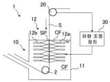
도 1 은, 본 발명의 실시형태에 관련된 ??칭 장치를 나타내는 모식도이다.
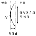
도 2 는, 금속판의 휨량의 정의의 일례를 나타내는 모식도이다.1 is a schematic diagram showing a quenching device according to an embodiment of the present invention.
Figure 2 is a schematic diagram showing an example of the definition of the amount of bending of a metal plate.
본 발명의 실시형태를 도면에 기초하여 설명한다. 도 1 은 본 발명의 실시형태에 관련된 ??칭 장치의 일례를 나타내는 모식도이다. 또한, 도 1 의 ??칭 장치 (1) 는, 예를 들어 금속판 (S) 으로서 강재의 ??칭을 실시하는 것으로, 연속 어닐링로의 균열대의 출측에 형성된 냉각 설비에 적용된다. 도 1 의 ??칭 장치 (1) 는, 금속판 (S) 을 냉각하는 냉각 장치 (10) 를 구비한다. 냉각 장치 (10) 는, 냉매 (CF) 를 사용하여 금속판을 냉각하는 것으로, 냉매 (CF) 를 저류하는 냉각조 (11) 와, 냉각조 (11) 내에 설치되고, 금속판 (S) 의 표면 및 이면에 냉매 (CF) 를 분사하는 복수의 분출 노즐 (12) 을 구비한다.Embodiments of the present invention will be described based on the drawings. 1 is a schematic diagram showing an example of a quenching device according to an embodiment of the present invention. In addition, the quenching device 1 in FIG. 1 quenches a steel material, for example, a metal plate S, and is applied to a cooling facility formed on the exit side of the crack zone of a continuous annealing furnace. The cooling device 1 in FIG. 1 is provided with a
냉각조 (11) 에는 냉매 (CF) 로서 물이 저류되어 있고, 예를 들면 냉각조 (11) 의 상면으로부터 금속판 (S) 이 통판 방향을 향해 침지해 간다. 냉각조 (11) 내의 냉매 (CF) 는, ??칭에 적절한 수온이 되도록 유지된다. 예를 들어, 냉각조 (11) 내의 수온으로는, 0 ℃ 초과 50 ℃ 이하가 바람직하고, 10 ℃ 이상 40 ℃ 이하가 특히 바람직하다. 냉각조 (11) 내의 냉매 (CF) 의 일부가, 외부의 쿨링 타워 등의 냉각 설비로 보내져 냉각된 후에, 냉각 후의 냉매 (CF) 가 냉각조 (11) 로 되돌려짐으로써, 냉각조 (11) 내의 수온 상승이 방지된다. 또한, 냉각조 (11) 내에는, 금속판 (S) 의 통판 방향을 변경하는 싱크 롤 (2) 이 설치되어 있다.Water is stored in the
복수의 분출 노즐 (12) 은, 금속판의 양면측의 각각에 금속판 (S) 의 통판 방향을 따라서 설치되어 있다. 따라서, 금속판 (S) 은, 냉각조 (11) 내의 냉매 (CF) 및 복수의 분출 노즐 (12) 로부터 분사되는 냉매 (CF) 에 의해 냉각된다. 복수의 분출 노즐 (12) 은, 금속판 (S) 의 이면측으로부터 금속판 (S) 에 냉매를 분사하여 급속 냉각을 실시하는 복수의 뒷측 분출 노즐 (12a) 과, 금속판 (S) 의 표면측으로부터 금속판 (S) 에 냉매 (CF) 를 분사하여 급속 냉각을 실시하는 복수의 앞측 분출 노즐 (12b) 을 구비한다. 복수의 뒷측 분출 노즐 (12a) 및 복수의 앞측 분출 노즐 (12b) 은, 각각 독립적으로 분사하는 냉매 (CF) 의 유량을 조정할 수 있다.A plurality of
뒷측 분출 노즐 (12a) 및 앞측 분출 노즐 (12b) 은, 도시하지 않은 배관에 접속되어 있고, 펌프에 의해 냉각조 (11) 내의 냉매 (CF) 가 배관 내로 퍼올려져, 뒷측 분출 노즐 (12a) 및 앞측 분출 노즐 (12b) 로 압송된다. 그리고, 뒷측 분출 노즐 (12a) 및 앞측 분출 노즐 (12b) 의 개구부로부터 고압수가 분출된다. 뒷측 분출 노즐 (12a) 및 앞측 분출 노즐 (12b) 은, 각각 금속판 (S) 의 앞측 및 뒷측에 대칭으로 배치하는 것이 바람직하고, 보다 폭 방향으로 균일한 냉각 능력을 얻기 위해서는 슬릿 노즐이 바람직하다.The
도 1 에 나타내는 바와 같이, 냉각조 (11) 및 복수의 분출 노즐 (12) 의 쌍방을 사용하여 금속판 (S) 을 냉각함으로써, 금속판 (S) 의 표면의 비등 (沸騰) 상태를 안정시키고, 균일한 형상 제어를 실시할 수 있다. 또한 도 1 에 있어서, 냉각 장치 (10) 는, 냉각조 (11) 와 복수의 분출 노즐 (12) 을 구비하고 있는 경우에 대해서 예시하고 있지만, 복수의 분출 노즐 (12) 을 구비하고 있으면, 냉각조 (11) 가 없어도 된다. 또한, 냉매 (CF) 로서 물을 사용한 워터 ??칭의 경우에 대해 예시하고 있지만, 냉매 (CF) 로서 오일을 사용한 유랭이어도 된다. 그리고, 냉각조 (11) 에 저류되고, 분출 노즐 (12) 로부터 분출되는 유체는, 냉매 (CF) 를 일례로 하는 냉각 유체이면 된다. 또한, 도 1 에 있어서, 복수의 분출 노즐 (12) 이 냉각조 (11) 내에 설치되어 있는 경우에 대해 예시하고 있지만, 금속판 (S) 을 원하는 온도 범위에서 냉각할 수 있는 수법이면, 냉각 방법은 이것에 한정되지 않는다.As shown in FIG. 1, by cooling the metal plate S using both the
여기서, ??칭 전의 금속판 (S) 에 이미 휨이 있는 경우, ??칭 후의 금속판 (S) 에도 휨이 잔류하는 경우가 있고, 나아가서는, 휨이 있는 금속판 (S) 에 대해 ??칭을 실시함으로써, 휨이 악화되어 버리는 경우가 있다. 이 때문에, ??칭 후의 금속판 (S) 의 휨의 발생을 억제하는 것이 요망되고 있으며, 나아가서는 ??칭 전의 금속판 (S) 의 휨을 ??칭에 의해 교정하는 것이 바람직하다. 그래서, 도 1 의 ??칭 장치 (1) 에서는, ??칭 전의 금속판 (S) 의 형상에 따라서 금속판 (S) 의 표면 및 이면의 각각의 냉각 능력을 설정하도록 되어 있다. 여기서, 금속판 (S) 의 「형상」은, 「휨 방향」 및 「휨량」이 포함된다. 그리고, 「휨 방향」은, 금속판 (S) 에 있어서의 「볼록한 휨 형상」과 동일한 의미이다.Here, when there is already a bend in the metal plate (S) before quenching, the bending may remain in the metal plate (S) after quenching, and further, quenching is performed on the warped metal plate (S). By carrying out this, the bending may worsen. For this reason, it is desired to suppress the occurrence of warping of the metal plate S after quenching, and furthermore, it is desirable to correct the warpage of the metal plate S before quenching by quenching. Therefore, in the quenching device 1 in FIG. 1, the cooling capabilities of the front and back surfaces of the metal plate S are set according to the shape of the metal plate S before quenching. Here, the “shape” of the metal plate S includes the “bending direction” and “bending amount.” In addition, “bending direction” has the same meaning as “convex bending shape” in the metal plate S.
??칭 전의 금속판 (S) 의 형상을 파악하는 방법은, 금속판 (S) 의 휨 방향 및 휨량을 파악할 수 있는 방법이면 특별히 한정되는 것은 아니다. ??칭 전의 금속판 (S) 의 형상은, ??칭 전의 통판되는 경로의 임의의 위치에서 측정한 형상을 바탕으로, ??칭 직전까지의 금속판 (S) 의 어닐링 조건이나, 금속판 (S) 의 반송 조건을 더한 물리 모델을 사용하여 산출해도 된다. 또한, ??칭 전의 금속판 (S) 의 형상은, 기계 학습 모델을 이용한 예측 모델을 사용하여 예측해도 된다. ??칭 직전에 형상 측정 장치를 형성하여, 금속판 (S) 의 형상의 측정을 실시해도 된다.The method of determining the shape of the metal plate S before quenching is not particularly limited as long as it is a method that can determine the bending direction and amount of bending of the metal plate S. The shape of the metal plate (S) before quenching is based on the shape measured at an arbitrary position along the path before quenching, and is based on the annealing conditions of the metal plate (S) just before quenching, or the shape of the metal plate (S) before quenching. It may be calculated using a physical model that adds the transport conditions of . In addition, the shape of the metal plate S before quenching may be predicted using a prediction model using a machine learning model. Immediately before quenching, a shape measuring device may be provided to measure the shape of the metal plate S.
또한, ??칭 후의 금속판 (S) (선행재) 의 형상의 측정에 있어서의 「휨 방향」 및 「휨량」에 기초하여, 후행재의 ??칭 전의 형상을 추정해도 된다. 구체적으로, 측정된 ??칭 후의 금속판 (S) (선행재) 의 휨량이, 과거의 제조 실적 (??칭 후의 휨량) 의 평균값보다 큰 경우에, ??칭 전에 존재한 휨이 영향을 미치고 있다고 판단하여, 금속판 (S) (후행재) 의 ??칭 전의 휨량 및 휨 방향을 추정해도 된다. 그리고, 추정된 후행재에 대해서 복수의 분출 노즐 (12) 에 있어서의 표면 및 이면의 유량 조정을 실시해도 된다.Additionally, the shape of the succeeding member before quenching may be estimated based on the “bending direction” and “bending amount” in the measurement of the shape of the metal plate S (preceding material) after quenching. Specifically, when the measured warp amount of the metal plate (S) (preceding material) after quenching is greater than the average value of past manufacturing performance (warpage amount after quenching), the warpage that existed before quenching has an influence. If it is determined that there is, the amount of bending and direction of bending of the metal plate (S) (post-material) before quenching may be estimated. In addition, the flow rate adjustment of the front and back surfaces of the plurality of
여기서, ??칭 전의 금속판 (S) 의 휨량을 정량적으로 파악할 수 있는 경우에는, 후술하는 바와 같이, 당해 휨량에 기초하여, 뒷측 분출 노즐 (12a) 및 앞측 분출 노즐 (12b) 로부터 분출하는 냉각 유체의 유량차를 결정하면 된다. 또한, ??칭 전의 금속판 (S) 의 휨량의 정량적인 파악을 할 수 없는 경우에는, 과거의 제조 실적으로서의 뒷측 분출 노즐 (12a) 및 앞측 분출 노즐 (12b) 로부터 분출하는 냉각 유체의 유량차, 및 당해 유량차에 대응하는 ??칭 후의 금속판 (S) 의 휨량 (보다 평탄화된 형상) 의 데이터에 기초하여, 뒷측 분출 노즐 (12a) 및 앞측 분출 노즐 (12b) 에 있어서의 냉각 유체의 유량을 결정해도 된다. 또한, ??칭 전의 금속판 (S) 의 휨 방향은, 연속 어닐링로의 입측의 원판 (原板) 의 형상이 반영되는 경향이 있어, 미리 원판의 휨 형상을 검지하거나 할 수 있으면, 그 정보를 바탕으로 표면 및 이면의 유량 조정을 실시해도 된다.Here, when the amount of deflection of the metal plate S before quenching can be quantitatively determined, the cooling fluid ejected from the
이하, 금속판 (S) 의 형상의 파악에 형상 측정 장치를 사용하는 경우의 실시형태에 대해 설명한다. 도 1 의 ??칭 장치 (1) 는, ??칭 전의 금속판의 형상을 측정하는 기능을 갖는 형상 측정 장치 (20) 와, 형상 측정 장치 (20) 에 의해 측정된 금속판 (S) 의 형상에 기초하여, 분출 노즐 (12) 로부터 금속판 (S) 의 표면 및 이면에 분사하는 냉매 (CF) 의 유량을 설정하는 유량 조정 장치 (30) 를 갖는다. 형상 측정 장치 (20) 는, 예를 들면 형상 측정 롤로 이루어져 있고, 구체적으로는 볼머사의 BFI 형상 롤이라고 불리는 제품을 사용할 수 있다. 형상 측정 장치 (20) 에는 폭 방향을 따라 복수의 압전 센서가 형성되어 있고, 금속판 (S) 이 형상 측정 장치 (20) 상을 통과함으로써 금속판 (S) 의 형상을 측정할 수 있다. 형상 측정 장치 (20) 는, 금속판 (S) 의 형상으로서, ??칭 전의 금속판 (S) 의 휨 방향을 측정하는 것으로, 바람직하게는 휨 방향 및 휨량을 측정한다.Hereinafter, an embodiment in the case where a shape measuring device is used to determine the shape of the metal plate S will be described. The quenching device 1 in FIG. 1 includes a
형상 측정 장치 (20) 와 냉각 개시점 (SP) 의 거리는 0.5 m 이상 2.0 m 이하인 것이 바람직하다. 형상의 측정은 가능한 한 냉각 개시점에 가까운 장소에서 실시하는 것이 바람직하지만, 0.5 m 미만이 되면, 냉각 장치와의 간섭이나, 냉각 유체의 비산에 의한 형상 측정 롤의 슬립 등이 우려되기 때문에 바람직하지 않다. 한편, 2.0 m 보다 멀어지면, 휨의 측정에서부터 냉각 개시까지의 사이에 휨이 변화될 가능성이 높기 때문에 피할 필요가 있다. 도 1 에는, 형상 측정 장치 (20) 가 형상 측정 롤로 이루어지는 경우에 대해 예시하고 있지만, 이것에 한정되지 않고, 예를 들면 카메라에 의한 계측이나 레이저 계측 등의 공지된 기술을 이용하여 ??칭 전의 금속판 (S) 의 형상을 측정해도 된다. 또한, 형상 측정 장치 (20) 와 냉각 개시점 (SP) 의 거리는, 구체적으로는, 형상 측정 장치에 있어서의 금속판 (S) 의 계측 지점에서부터 냉각 개시점 (SP) 까지의 거리이다. 금속판 (S) 의 형상을 예측하는 경우도, 냉각 개시점 (SP) 에 가능한 한 가까운 위치의 금속판 (S) 의 형상을 예측하는 것이 바람직하다.The distance between the
유량 조정 장치 (30) 는, 금속판 (S) 의 형상에 맞춰서, 뒷측 분출 노즐 (12a) 및 앞측 분출 노즐 (12b) 로부터의 냉매 (CF) 의 분사량을 설정한다. 상기 서술한 바와 같이, 뒷측 분출 노즐 (12a) 및 앞측 분출 노즐 (12b) 로부터 분출하는 냉각 유체의 유량이 펌프에 의해 제어되고 있는 경우, 유량 조정 장치 (30) 는 펌프의 동작을 제어함으로써 냉각 유체의 유량을 제어한다. 또한, 뒷측 분출 노즐 (12a) 및 앞측 분출 노즐 (12b) 로부터의 냉매 (CF) 의 분사량은, 워터 ??칭의 경우, 각각 200 m3/hr 이상인 것이 바람직하다. 200 m3/hr 보다 적으면, 금속판 (S) 의 피냉각면에 발생하는 증기막을 충분히 제거할 수 없게 되기 때문이다.The flow
유량 조정 장치 (30) 는, ??칭 전의 금속판 (S) 이 표면측으로 볼록한 휨 형상일 경우, 금속판 (S) 의 앞측 분출 노즐 (12b) 의 유량보다 뒷측 분출 노즐 (12a) 의 유량을 크게 한다. 한편, 유량 조정 장치 (30) 는 ??칭 전의 금속판 (S) 이 이면측으로 볼록한 휨 형상일 경우, 금속판의 이면측의 유량보다 뒷측 분출 노즐 (12b) 의 유량을 크게 한다.When the metal plate S before quenching has a curved shape that is convex toward the surface, the flow
연속 어닐링 설비에 있어서는, 금속판 (S) 의 반송 방향으로 장력이 부여되어 있다. 그 때문에, 금속판 (S) 의 앞측과 뒷측의 냉각 속도가 상이하도록 변화시키면, 강(强)냉각면측이 냉각 후에 볼록한 휨 형상이 된다. 이 현상은, 강냉각면측이 보다 크게 열수축하려고 하면, 약(弱)냉면으로부터 폭 방향의 인장 응력을 받기 때문에, 강냉면측에는 인장 방향, 약냉면측에는 압축 방향의 잔류 응력이 발생하는 것에서 기인한다. 이 잔류 응력에 의해, 냉각 종료 후, 강냉각면쪽이 볼록한 형상으로 휘는 경향이 있다.In continuous annealing equipment, tension is applied in the conveyance direction of the metal plate S. Therefore, if the cooling rates on the front and back sides of the metal plate S are changed to be different, the steel cooling surface side becomes a convex curved shape after cooling. This phenomenon is caused by the fact that when the strongly cooled surface side tries to thermally contract to a greater extent, it receives tensile stress in the width direction from the weakly cooled surface, so residual stress occurs in the tensile direction on the strongly cooled surface side and in the compressive direction on the weakly cooled surface side. Due to this residual stress, the strongly cooled surface tends to bend into a convex shape after cooling is completed.
이것을 이용하여, ??칭 전의 강판에 이미 휨이 있었던 경우, 그 휨의 오목측의 면의 냉각 속도를 볼록측의 면의 냉각 속도보다 크게 한다. 이로써, ??칭 전의 금속판 (S) 에 휨이 발생되어 있는 경우에도 ??칭 후의 형상을 평탄하게 제어할 수 있다. 그래서, 금속판 (S) 의 휨의 형상을 파악한 후에, 오목측의 면으로 되어 있는 쪽에 설치되어 있는 노즐로부터 분출되는 냉각 유체의 유량을 올림으로써, 휨을 개선할 수 있다.Using this, when there is already warpage in the steel sheet before quenching, the cooling rate of the surface on the concave side of the bending is made larger than the cooling rate of the surface on the convex side. As a result, even when bending occurs in the metal plate S before quenching, the shape after quenching can be controlled to be flat. Therefore, after determining the shape of the bending of the metal plate S, the bending can be improved by increasing the flow rate of the cooling fluid ejected from the nozzle installed on the side of the concave side.
도 2 는, 휨량 (d) 의 정의를 나타내는 모식도이다. 유량 조정 장치 (30) 는, 휨 방향뿐만 아니라 휨량 (d) 도 냉매 (CF) 의 분사량에 반영시키는 것이 바람직하다. 유량 조정 장치 (30) 는, 금속판 (S) 의 휨량 (d) 이 커질수록, 금속판 (S) 의 표면에 분사하는 냉각 유체의 유량과 이면에 분사하는 냉각 유체의 유량의 유량차를 크게 한다. 유량 조정 장치 (30) 에는, 예를 들면 휨량 (d) 과 유량차의 관계가 미리 설정되어 있고, 측정된 휨 방향 및 휨량 (d) 에 따라서 뒷측 분출 노즐 (12a) 및 앞측 분출 노즐 (12b) 로부터 분출하는 냉매 (CF) 의 유량이 설정된다.Figure 2 is a schematic diagram showing the definition of the amount of deflection (d). The flow
특히, ??칭 전에 발생한 휨량을 d (mm) 로 하고, 냉각시의 냉각 유체의 유량차를 Q (m3/hr) 로 했을 때, d 의 값에 대하여 0 ≤ Q < 20d+200 으로 하는 것이 바람직하다. 여기서, Q = 0 (m3/hr) 은, 휨이 측정 또는 예측되지 않은 상태이며, 앞측 및 뒷측 어느 분사 유량도 동등하게 하면 되는 것에 기초한다. 한편, 유량차 Q 가 20d+200 (m 3/hr) 이상이 되면, 유량차에 의한 냉각 능력의 차에 의해, 냉각 전의 휨과는 반대 방향으로 휘기 시작한다. 냉각 개시 전의 휨량 (d) (mm) 에 대하여, 10d (m3/hr) 로 사전의 휨이 개선되고, 또한 강판이라면, 냉각 중에 발생하는 휨이 10 mm 정도이기 때문에, 현실적으로는 0 ≤ Q ≤ 10d+100 (m3/hr) 가 적합하다.In particular, when the amount of deflection occurring before quenching is d (mm) and the flow rate difference of the cooling fluid during cooling is Q (m 3 /hr), it is desirable to set the value of d to 0 ≤ Q < 20d + 200. do. Here, Q = 0 (m 3 /hr) is based on the fact that the deflection is not measured or predicted, and the injection flow rates on both the front and rear sides are made equal. On the other hand, when the flow rate difference Q becomes 20d+200 (m 3 /hr) or more, it begins to bend in the opposite direction to the bending before cooling due to the difference in cooling capacity due to the flow rate difference. With respect to the amount of deflection (d) (mm) before the start of cooling, the pre-deflection is improved by 10d (m 3 /hr), and if it is a steel plate, the deflection that occurs during cooling is about 10 mm, so in reality, 0 ≤ Q ≤ 10d+100 (m 3 /hr) is suitable.
도 1 을 참조하여 본 발명의 ??칭 방법 및 강판의 제조 방법에 대해 설명한다. 먼저, ??칭 전의 금속판 (S) 의 휨 방향 및 휨량 (d) 의 형상이 파악된다. 유량 조정 장치 (30) 에 있어서, 금속판 (S) 의 형상에 따라서, 앞측 분출 노즐 (12b) 및 뒷측 분출 노즐 (12a) 의 유량이 설정된다. 그리고, 금속판 (강판) 이 반송되면서 냉각 장치 (10) 에 의해 냉각되어, 금속판 (S) 의 ??칭이 실시된다. 구체적으로는, 표면측으로 볼록한 휨 형상인 경우, 뒷측 분출 노즐 (12a) 의 유량이 앞측 분출 노즐 (12b) 보다 크게 설정되고, ??칭 전의 금속판 (S) 이 이면측으로 볼록한 휨 형상인 경우, 앞측 분출 노즐 (12b) 이 뒷측 분출 노즐 (12a) 의 유량보다 크게 설정된다. 또한, 이 유량차는, 휨량 (d) 에 의해 설정된다.Referring to FIG. 1, the quenching method and the steel sheet manufacturing method of the present invention will be described. First, the shape of the bending direction and bending amount (d) of the metal plate (S) before quenching is determined. In the flow
상기 실시형태에 따르면, ??칭 전의 금속판 (S) 의 형상을 파악하고, 금속판 (S) 의 형상에 따라서 표면 및 이면에 분사하는 냉각 유체의 유량을 설정한다. 이로써, 금속판 (S) 을 연속적으로 반송하면서 ??칭을 실시할 때에, ??칭 전의 금속판에 휨이 있었던 경우라도, ??칭 중의 휨의 조장을 억제하고, ??칭 후의 금속판의 휨을 억제할 수 있다.According to the above embodiment, the shape of the metal plate S before quenching is determined, and the flow rate of the cooling fluid sprayed on the front and back surfaces is set according to the shape of the metal plate S. As a result, when quenching is performed while continuously transporting the metal plate S, even if there is bending in the metal plate before quenching, the promotion of warpage during quenching is suppressed, and the bending of the metal plate after quenching is suppressed. can do.
종래의 금속판의 ??칭에서는, ??칭 전의 금속판에 이미 휨이 있었던 경우, ??칭에 의해 그 휨이 더욱 커진다. ??칭에 의해 금속판에 작용하는 굽힘 모멘트는, ??칭 전에 이미 휨이 있었던 경우, 휨을 되돌리는 방향으로의 저항이 있기 때문에, 보다 휨을 조장하는 방향으로 작용한다. 그 때문에, ??칭 전의 금속판의 휨 방향과, ??칭 후의 금속판의 휨 방향은 동일하며, 또한 휨량은 ??칭 전보다도 커진다.In the conventional quenching of a metal plate, if there is already a bend in the metal plate before quenching, the bending increases further due to quenching. The bending moment applied to the metal plate by quenching acts in a direction that promotes bending more because there is resistance in the direction of returning the bending when there has already been bending before quenching. Therefore, the bending direction of the metal plate before quenching and the bending direction of the metal plate after quenching are the same, and the amount of bending is larger than before quenching.
종래의 ??칭에서는, ??칭 전의 휨을 고려하지 않았기 때문에, 강판의 피냉각면은 표면 및 이면에서 균일하게 냉각하는 것이 강판 형상에 있어서 이상적으로 되어 있다. 그러나, 사전에 휨이 있는 것을 파악하고 있으면, 그 휨에 따라서 휨을 교정시키는 방향으로 대책을 강구할 수 있다. 따라서, 휨을 파악함으로써 계속되는 ??칭시의 냉각 속도를 제어하고, 휨을 교정할 수 있는 것에 착안하여, ??칭 전의 금속판 (S) 의 형상을 파악하고, 금속판 (S) 의 형상에 따라서 표면 및 이면에 분사하는 냉각 유체의 유량을 설정한다. 이로써, ??칭 전의 금속판 (S) 에 휨이 있었던 경우에도, ??칭 후의 금속판의 휨을 억제할 수 있다.In conventional quenching, the bending before quenching is not taken into consideration, so the ideal shape of the steel sheet is for the surface to be cooled to be cooled uniformly on the front and back surfaces. However, if it is known in advance that there is bending, measures can be taken to correct the bending according to the bending. Therefore, focusing on the fact that the cooling rate during continued quenching can be controlled and the warpage corrected by determining the warpage, the shape of the metal plate (S) before quenching is determined, and the surface and back surfaces are determined according to the shape of the metal plate (S). Set the flow rate of the cooling fluid sprayed. As a result, even when there is bending in the metal plate S before quenching, the bending of the metal plate after quenching can be suppressed.
특히 본 발명은, 금속판 (S) 의 급랭 중에 마텐자이트 변태가 일어나 조직이 체적 팽창할 때에 발생하는 복잡하고 불균일한 요철상의 형상을 저감시킬 수 있다. 따라서, 금속판 (S) 이 고강도 강판 (하이텐) 일 때, 변형 억제 효과가 커진다. 특히, ??칭 장치 (1) 는, 금속판 (S) 이 고강도 강판인 경우의 ??칭에 적용하는 것이 바람직하다. 보다 구체적으로, 인장 강도가 580 MPa 이상인 강판의 제조에 적용하는 것이 바람직하다. 인장 강도의 상한은 특별히 제한되지 않지만, 일례로서 2000 MPa 이하이면 된다. 상기의 고강도 강판 (하이텐) 으로는, 고강도 냉연 강판, 및 그것들에 표면 처리 (도금 처리) 를 실시한 용융 아연 도금 강판 (용융 아연 도금 처리 강판), 전기 아연 도금 강판 (전기 아연 도금 처리 강판), 합금화 용융 아연 도금 강판 (합금화 용융 아연 도금 처리 강판) 등이 있다. 고강도 강판의 조성의 구체예로서, 질량% 로, C 가 0.04 % 이상 0.35 % 이하, Si 가 0.01 % 이상 2.50 % 이하, Mn 이 0.80 % 이상 3.70 % 이하, P 가 0.001 % 이상 0.090 % 이하, S 가 0.0001 % 이상 0.0050 % 이하, sol.Al 이 0.005 % 이상 0.065 % 이하, 필요에 따라서, Cr, Mo, Nb, V, Ni, Cu, 및 Ti 중 적어도 1 종 이상이 각각 0.5 % 이하, 추가로 필요에 따라서, B, Sb 가 각각 0.01 % 이하, 잔부가 Fe 및 불가피적 불순물로 이루어지는 예를 들 수 있다. 또한, 본 발명의 실시형태는, 강판을 ??칭하는 예에 한정되는 것이 아니라, 강판 이외의 금속판 전반의 ??칭에 적용할 수 있다.In particular, the present invention can reduce the complex and uneven uneven shape that occurs when martensitic transformation occurs during rapid cooling of the metal plate S and the structure expands in volume. Therefore, when the metal plate (S) is a high-strength steel plate (High Ten), the deformation suppression effect increases. In particular, the quenching device 1 is preferably applied to quenching when the metal plate S is a high-strength steel sheet. More specifically, it is desirable to apply it to the production of steel sheets with a tensile strength of 580 MPa or more. The upper limit of the tensile strength is not particularly limited, but may be 2000 MPa or less as an example. The above high-strength steel sheet (Hi-ten) includes high-strength cold-rolled steel sheet, hot-dip galvanized steel sheet (hot-dip galvanized steel sheet), and electro-galvanized steel sheet (electro-galvanized steel sheet) to which surface treatment (plating treatment) has been applied. There are alloyed hot-dip galvanized steel sheets (alloyed hot-dip galvanized steel sheets), etc. As a specific example of the composition of the high-strength steel sheet, in mass%, C is 0.04% or more and 0.35% or less, Si is 0.01% or more and 2.50% or less, Mn is 0.80% or more and 3.70% or less, P is 0.001% or more and 0.090% or less, and S is 0.0001% or more and 0.0050% or less, sol.Al is 0.005% or more and 0.065% or less, and, if necessary, at least one of Cr, Mo, Nb, V, Ni, Cu, and Ti is 0.5% or less each, additionally If necessary, an example may be given in which B and Sb are each 0.01% or less, and the remainder is Fe and inevitable impurities. In addition, the embodiment of the present invention is not limited to the example of quenching a steel plate, but can be applied to quenching of all metal plates other than steel plates.
실시예Example
본 발명의 실시예를 서술한다. 본 발명예 1 ∼ 14 로서, 도 1 의 ??칭 장치 (1) 를 사용하여 판두께가 1.0 mm, 판폭이 1000 mm 인 인장 강도 1470 MPa 급의 고장력 냉연 강판을 금속판 (S) 으로서 제조하였다. 또한, 인장 강도 1470 MPa 급의 고장력 냉연 강판의 조성은, 질량% 로, C 가 0.20 %, Si 가 1.0 %, Mn 이 2.3 %, P 가 0.005 %, S 가 0.002 % 이다. 냉매 (CF) 로서 물을 사용하고, 물의 온도는 30 ℃ 로 하였다.An embodiment of the present invention is described. In Examples 1 to 14 of the present invention, a high-strength cold-rolled steel sheet with a sheet thickness of 1.0 mm and a sheet width of 1000 mm and a tensile strength of 1470 MPa grade was manufactured as a metal sheet (S) using the quenching device 1 of FIG. 1. In addition, the composition of the high-strength cold-rolled steel sheet with a tensile strength of 1470 MPa class, in mass%, is 0.20% C, 1.0% Si, 2.3% Mn, 0.005% P, and 0.002% S. Water was used as the refrigerant (CF), and the temperature of the water was 30°C.
한편, 비교예 1 ∼ 6 으로서, 특허문헌 1 에 나타낸 ??칭 장치를 사용하고, 그 밖의 조건은 본 발명예와 동일하게 하여, 상기의 고장력 냉연 강판을 제조하였다. 그리고, 본 발명예 1 ∼ 12 및 비교예 1 ∼ 6 에 대해서, ??칭 전의 금속판 (S) 의 휨량과, ??칭 후의 금속판 (S) 의 휨량의 관계를 측정하였다. 본 발명예 13, 14 에 대해서는, ??칭 전의 금속판 (S) 의 「휨 방향」 및 「휨량」의 측정은 행하지 않고, ??칭 전의 「휨 방향」 및 「휨량」을 추정하여 실시하였다. 또한, 휨량의 정의는 도 2 에 나타내며, 본 발명예 1 ∼ 12 및 비교예 1 ∼ 6 에 대해서는, ??칭 후의 금속판 (S) 의 휨량이 ??칭 전의 휨량 이하로 되어 있으면, 휨이 억제되어 있는 것으로 판단하였다. 또한, 본 발명예 13, 14 에 대해서는, ??칭 후의 금속판 (S) (후행재) 의 휨량이 ??칭 후의 금속판 (S) (선행재) 의 휨량 이하로 되어 있으면, 휨이 억제되어 있는 것으로 판단하였다. 본 발명예 1 ∼ 14 와 비교예 1 ∼ 6 의 휨량을 하기 표 1 에 나타낸다.On the other hand, as Comparative Examples 1 to 6, the above high-strength cold-rolled steel sheets were manufactured using the quenching device shown in Patent Document 1 and other conditions being the same as those of the present invention example. And, for Invention Examples 1 to 12 and Comparative Examples 1 to 6, the relationship between the amount of warping of the metal plate (S) before quenching and the amount of warping of the metal plate (S) after quenching was measured. For invention examples 13 and 14, the “bending direction” and “bending amount” of the metal plate S before quenching were not measured, but the “bending direction” and “bending amount” before quenching were estimated. In addition, the definition of the amount of warping is shown in FIG. 2, and for Invention Examples 1 to 12 and Comparative Examples 1 to 6, if the amount of warping of the metal plate S after quenching is less than the amount of warping before quenching, the warping is suppressed. It was judged that it was done. Additionally, regarding the present invention examples 13 and 14, if the amount of warping of the metal plate (S) (successor material) after quenching is less than or equal to the amount of warping of the metal plate (S) (preceding material) after quenching, the warping is suppressed. It was judged that it was. The amount of warpage of invention examples 1 to 14 and comparative examples 1 to 6 is shown in Table 1 below.

표 1 에 나타내는 바와 같이, 본 발명예 1 ∼ 14 에서는, ??칭 전의 금속판 (S) 에 이미 휨이 있었던 경우라도, ??칭 후의 금속판 (S) 의 휨을 억제할 수 있었다. 특히, 본 발명예 2, 4, 6, 8, 10, 12 와 같이, 휨 방향뿐만 아니라 휨량 (d) 에 따라서 유량차를 설정한 경우, ??칭 전의 금속판 (S) 의 휨을, ??칭 후에는 0 mm 로 할 수 있었다. 한편, 비교예 1 ∼ 6 에서는, ??칭 전의 금속판 (S) 에 이미 휨이 있었던 경우에는, ??칭 후의 금속판 (S) 의 휨이 커져 버렸다.As shown in Table 1, in Examples 1 to 14 of the present invention, even when the metal plate S before quenching already had bending, the bending of the metal plate S after quenching could be suppressed. In particular, when the flow rate difference is set not only according to the bending direction but also the bending amount (d), as in Examples 2, 4, 6, 8, 10, and 12 of the present invention, the bending of the metal plate (S) before quenching is quenched. Later it was possible to set it to 0 mm. On the other hand, in Comparative Examples 1 to 6, when the metal plate S before quenching already had curvature, the warp of the metal plate S after quenching increased.
본 발명예 13, 14 에 있어서는, 금속판 (S) (선행재) 의 ??칭 후의 휨 방향 및 휨량을 카메라 화면에서 육안으로 확인함으로써, 금속판 (S) (후행재) 의 ??칭 전의 형상을 추정하였다. 구체적으로, 금속판 (S) (선행재) 의 ??칭 후의 휨량의 계측은, 금속판 (S) 의 에지측 (폭 방향의 양단측) 에서부터 촬영한 화상을 사용하여, 휨량이 극대가 되는 위치를 화상 해석으로 검출하고, 실스케일에 맞춤으로써 측정하였다. 그리고, 과거의 제조 실적 (??칭 후의 휨량) 의 평균값과 비교하여 측정된 휨량이 큰 경우에, ??칭 전의 금속판 (S) 의 형상에 휨이 존재한다고 판단하였다. 또한, 「휨이 존재한다」고 판단한 경우에, 과거의 제조 실적 (??칭 후의 휨량) 의 평균값과 측정된 휨량과의 괴리차로부터, ??칭 전의 휨량을 추정하였다. 그 때문에, 미리 제조 실적을 수집해 두고, 제조 실적 (??칭 후의 휨량) 의 평균값과 측정된 휨량과의 괴리차와, ??칭 전의 휨량과의 상관 관계를 미리 파악해 두는 것이 바람직하다. 또한 금속판 (S) (후행재) 의 휨 방향의 추정은, ??칭 전후에 있어서의 금속판 (S) 의 휨 방향이 동일한 것으로 하여, 금속판 (S) (선행재) 의 휨 방향에 기초하여 추정하였다.In Examples 13 and 14 of the present invention, the shape of the metal plate (S) (successor material) before quenching was confirmed by visually checking the bending direction and amount of bending of the metal plate (S) (preceding material) after quenching on the camera screen. It was estimated. Specifically, the measurement of the amount of deflection of the metal plate S (preceding material) after bending is performed using images taken from the edge side (both ends in the width direction) of the metal plate S, and the position where the amount of deflection is maximized is determined. It was detected by image analysis and measured by adjusting to real scale. And, when the measured amount of warp was large compared to the average value of past manufacturing performance (amount of warp after quenching), it was determined that warp existed in the shape of the metal plate S before quenching. In addition, when it was determined that “warpage exists,” the amount of warp before quenching was estimated from the difference between the average value of past manufacturing performance (the amount of warp after quenching) and the measured warp amount. Therefore, it is desirable to collect the manufacturing performance in advance and understand in advance the correlation between the average value of the manufacturing performance (the amount of warpage after quenching) and the measured warpage amount and the amount of warpage before quenching. Additionally, the bending direction of the metal plate S (successor material) is estimated based on the bending direction of the metal plate S (preceding material), assuming that the bending direction of the metal plate S before and after quenching is the same. did.
그리고, 추정한 금속판 (S) (후행재) 의 ??칭 전의 「휨 방향」 및 「휨량」에 기초하여, 금속판 (S) (후행재) 의 표면 및 이면의 분사 유량의 조정을 실시함으로써, 동일 조건에서의 후행재에 있어서, ??칭 후의 휨량을 개선할 수 있음을 확인할 수 있었다. 또한, 동일 제조 조건의 동일 코일에 있어서는, ??칭 전의 휨량이 길이 방향으로 대폭 변동되지 않기 때문에, ??칭 후의 휨량을 확인하면서, ??칭 전의 휨 형상의 유무, 휨 방향 및 휨량을 판단하여, 금속판 (S) 의 표면 및 이면의 분사 유량의 조정을 실시함으로써, ??칭 후의 휨량을 개선할 수 있음을 확인할 수 있었다.Then, based on the estimated “bending direction” and “bending amount” of the metal plate S (following material) before quenching, the spray flow rate on the front and back surfaces of the metal plate S (following material) is adjusted, It was confirmed that the amount of warpage after quenching could be improved in the lagging material under the same conditions. In addition, for the same coil under the same manufacturing conditions, the amount of warp before quenching does not vary significantly in the longitudinal direction, so while checking the amount of warp after quenching, the presence or absence of the bent shape before quenching, the bending direction, and the amount of bending can be determined. Thus, it was confirmed that the amount of warpage after quenching could be improved by adjusting the spray flow rate on the front and back surfaces of the metal plate S.
본 발명예에서는, ??칭 후의 휨량을 0 mm 로 하는 실시예도 포함되지만, 통판 경로의 설비의 사정 등에 의해, 금속판 (S) 의 일방의 면 (표면 또는 이면) 의 휨량의 허용 범위가 좁은 경우에, 타방의 면 (이면 또는 표면) 으로 휨 방향을 바꾸는 등의, 휨 방향의 조정도 가능하다.In the example of the present invention, an embodiment in which the amount of deflection after quenching is set to 0 mm is also included, but in cases where the allowable range of the amount of deflection of one side (front or back) of the metal plate S is narrow due to the circumstances of the equipment of the distribution route, etc. It is also possible to adjust the bending direction, such as changing the bending direction to the other side (back side or front surface).
1 : ??칭 장치
10 : 냉각 장치
11 : 냉각조
12 : 분출 노즐
12a : 뒷측 분출 노즐
12b : 앞측 분출 노즐
20 : 형상 측정 장치
30 : 유량 조정 장치
CF : 냉매
S : 금속판 (강판)
SP : 냉각 개시점
d : 휨량1: Quenching device
10: Cooling device
11: cooling tank
12: Blowout nozzle
12a: rear blowout nozzle
12b: Front blowout nozzle
20: Shape measurement device
30: flow adjustment device
CF: refrigerant
S: Metal plate (steel plate)
SP: Cooling start point
d: amount of deflection
Claims (12)
상기 금속판의 표면 및 이면에 냉각 유체를 분사하는 복수의 분출 노즐을 구비하는 냉각 장치와,
??칭 전의 상기 금속판의 형상에 기초하여, 상기 분출 노즐로부터 상기 금속판의 표면 및 이면에 분사하는 냉각 유체의 유량을 설정하는 유량 조정 장치를 갖고,
상기 유량 조정 장치는, ??칭 전의 상기 금속판이 표면측으로 볼록한 휨 형상인 경우에는 상기 금속판의 표면측보다 이면측의 유량을 크게 설정하고, ??칭 전의 상기 금속판이 이면측으로 볼록한 휨 형상인 경우에는 상기 금속판의 이면측보다 표면측의 유량을 크게 설정하는, ??칭 장치.As a cooling device for cooling a metal plate,
A cooling device having a plurality of jet nozzles that spray cooling fluid on the front and back surfaces of the metal plate;
It has a flow rate adjustment device that sets the flow rate of the cooling fluid sprayed from the jet nozzle to the front and back surfaces of the metal plate based on the shape of the metal plate before quenching,
The flow rate adjustment device sets the flow rate on the back side of the metal plate to be larger than that on the front side of the metal plate when the metal plate before quenching has a curved shape that is convex toward the back side, and when the metal plate before quenching has a curved shape that is convex toward the back side. A quenching device in which the flow rate on the surface side of the metal plate is set to be larger than that on the back side.
상기 금속판의 형상은, ??칭 전의 상기 금속판의 형상을 측정하는 형상 측정 장치에 의해 측정되는, ??칭 장치.According to claim 1,
A quenching device in which the shape of the metal plate is measured by a shape measuring device that measures the shape of the metal plate before quenching.
상기 형상 측정 장치는, 상기 금속판의 휨량을 측정하는 기능을 갖고,
상기 유량 조정 장치는, 상기 금속판의 휨량이 커질수록, 상기 금속판의 표면에 분사하는 냉각 유체의 유량과 이면에 분사하는 냉각 유체의 유량의 유량차를 크게 설정하는 ??칭 장치.According to claim 2,
The shape measuring device has a function of measuring the amount of bending of the metal plate,
The flow rate adjustment device sets the flow rate difference between the flow rate of the cooling fluid sprayed on the surface of the metal plate and the flow rate of the cooling fluid sprayed on the back side to be larger as the amount of deflection of the metal plate increases.
상기 금속판의 표면에 분사하는 냉각 유체의 유량과 이면에 분사하는 냉각 유체의 유량의 유량차는, 휨량을 d (mm) 로 했을 때, 20×d+200 (m3/hr) 미만인 ??칭 장치.According to claim 3,
The flow rate difference between the flow rate of the cooling fluid sprayed on the surface of the metal plate and the flow rate of the cooling fluid sprayed on the back surface is less than 20 × d + 200 (m 3 /hr) when the deflection amount is d (mm).
상기 형상 측정 장치는, ??칭 전의 상기 금속판이 통과하는 형상 측정 롤로 이루어지고,
상기 형상 측정 장치와 상기 냉각 장치에 의한 냉각 개시점의 거리는 0.5 m 이상 2.0 m 이하인 ??칭 장치.According to any one of claims 2 to 4,
The shape measuring device consists of a shape measuring roll through which the metal plate before quenching passes,
A cooling device wherein the distance between the shape measuring device and the cooling start point by the cooling device is 0.5 m or more and 2.0 m or less.
??칭 전의 상기 금속판의 형상에 기초하여, 상기 분출 노즐로부터 상기 금속판의 표면 및 이면에 분사하는 냉각 유체의 유량을 설정할 때, 상기 금속판이 표면측으로 볼록한 휨 형상인 경우에는 상기 금속판의 표면측보다 이면측의 유량을 크게 하고, 상기 금속판이 이면측으로 볼록한 휨 형상인 경우에는 상기 금속판의 이면측보다 표면측의 유량을 크게 하는 ??칭 방법.A cooling method of cooling a metal plate by spraying cooling fluid on the front and back surfaces of the metal plate from a plurality of jet nozzles,
When setting the flow rate of the cooling fluid sprayed from the jet nozzle to the front and back surfaces of the metal plate based on the shape of the metal plate before quenching, if the metal plate has a curved shape that is convex toward the surface, the flow rate is greater than the surface side of the metal plate. A quenching method in which the flow rate on the back side is increased, and when the metal plate has a curved shape that is convex toward the back side, the flow rate on the front side is made larger than that on the back side of the metal plate.
상기 금속판의 형상 중, 상기 금속판의 휨량을 파악하고,
냉각 유체의 유량을 설정할 때, 상기 금속판의 휨량이 커질수록, 상기 금속판의 표면에 분사하는 냉각 유체의 유량과 이면에 분사하는 냉각 유체의 유량의 유량차를 크게 하는 ??칭 방법.According to claim 7,
Among the shapes of the metal plate, determine the amount of bending of the metal plate,
When setting the flow rate of the cooling fluid, as the amount of deflection of the metal plate increases, the flow rate difference between the flow rate of the cooling fluid sprayed on the surface of the metal plate and the flow rate of the cooling fluid sprayed on the back side increases.
상기 금속판의 표면에 분사하는 냉각 유체의 유량과 이면에 분사하는 냉각 유체의 유량의 유량차는, 휨량을 d (mm) 로 했을 때, 20×d+200 (m3/hr) 미만인 ??칭 방법.According to claim 8,
The flow rate difference between the flow rate of the cooling fluid sprayed on the surface of the metal plate and the flow rate of the cooling fluid sprayed on the back side is less than 20 × d + 200 (m 3 /hr) when the deflection amount is d (mm).
상기 도금 처리가, 용융 아연 도금 처리, 전기 아연 도금 처리 및 합금화 용융 아연 도금 처리 중 어느 것인 도금 강판의 제조 방법.According to claim 11,
A method of manufacturing a plated steel sheet, wherein the plating treatment is any one of hot-dip galvanizing treatment, electrogalvanizing treatment, and alloyed hot-dip galvanizing treatment.
Applications Claiming Priority (3)
| Application Number | Priority Date | Filing Date | Title |
|---|---|---|---|
| JP2021150948 | 2021-09-16 | ||
| JPJP-P-2021-150948 | 2021-09-16 | ||
| PCT/JP2022/034060 WO2023042794A1 (en) | 2021-09-16 | 2022-09-12 | Quenching device, continuous annealing equipment, quenching method, method for manufacturing steel sheet, and method for manufacturing plated steel sheet |
Publications (1)
| Publication Number | Publication Date |
|---|---|
| KR20240046536A true KR20240046536A (en) | 2024-04-09 |
Family
ID=85602884
Family Applications (1)
| Application Number | Title | Priority Date | Filing Date |
|---|---|---|---|
| KR1020247007663A KR20240046536A (en) | 2021-09-16 | 2022-09-12 | Quenching device and continuous annealing equipment, and quenching method, manufacturing method of steel sheet, and manufacturing method of plated steel sheet |
Country Status (5)
| Country | Link |
|---|---|
| EP (1) | EP4365320A1 (en) |
| JP (1) | JP7306590B1 (en) |
| KR (1) | KR20240046536A (en) |
| CN (1) | CN117999366A (en) |
| WO (1) | WO2023042794A1 (en) |
Citations (2)
| Publication number | Priority date | Publication date | Assignee | Title |
|---|---|---|---|---|
| JPS59153843A (en) | 1983-02-18 | 1984-09-01 | Nippon Kokan Kk <Nkk> | Cooling method of strip |
| JP2011184773A (en) | 2010-03-10 | 2011-09-22 | Kobe Steel Ltd | Continuous annealing apparatus, and method for suppressing corrugation deformation of metal sheet during quenching in the same |
Family Cites Families (4)
| Publication number | Priority date | Publication date | Assignee | Title |
|---|---|---|---|---|
| JPH0987752A (en) * | 1995-09-25 | 1997-03-31 | Kawasaki Steel Corp | Device for cooling steel strip and method for restraining curving or steel strip |
| JP4464567B2 (en) | 2001-01-31 | 2010-05-19 | 古河スカイ株式会社 | Continuous quenching method for aluminum alloy strip |
| CN101928811A (en) | 2009-06-23 | 2010-12-29 | 宝山钢铁股份有限公司 | Steel plate quenching method based on model control |
| JP7314989B2 (en) | 2019-03-29 | 2023-07-26 | Jfeスチール株式会社 | Quenching device and method for manufacturing metal plate |
-
2022
- 2022-09-12 JP JP2022575215A patent/JP7306590B1/en active Active
- 2022-09-12 CN CN202280060385.3A patent/CN117999366A/en active Pending
- 2022-09-12 EP EP22869941.9A patent/EP4365320A1/en active Pending
- 2022-09-12 WO PCT/JP2022/034060 patent/WO2023042794A1/en active Application Filing
- 2022-09-12 KR KR1020247007663A patent/KR20240046536A/en unknown
Patent Citations (2)
| Publication number | Priority date | Publication date | Assignee | Title |
|---|---|---|---|---|
| JPS59153843A (en) | 1983-02-18 | 1984-09-01 | Nippon Kokan Kk <Nkk> | Cooling method of strip |
| JP2011184773A (en) | 2010-03-10 | 2011-09-22 | Kobe Steel Ltd | Continuous annealing apparatus, and method for suppressing corrugation deformation of metal sheet during quenching in the same |
Also Published As
| Publication number | Publication date |
|---|---|
| JPWO2023042794A1 (en) | 2023-03-23 |
| CN117999366A (en) | 2024-05-07 |
| WO2023042794A1 (en) | 2023-03-23 |
| JP7306590B1 (en) | 2023-07-11 |
| EP4365320A1 (en) | 2024-05-08 |
Similar Documents
| Publication | Publication Date | Title |
|---|---|---|
| KR101987566B1 (en) | Method for manufacturing metal sheet and rapid quenching unit | |
| CN108474052B (en) | Quenching apparatus and quenching method | |
| US10927441B2 (en) | High-strength galvanized hot-rolled steel sheet and method for manufacturing same | |
| JP6687084B2 (en) | Quenching and quenching apparatus, quenching and quenching method, and method for manufacturing metal plate product | |
| CN114555846B (en) | Steel sheet, component, and method for producing same | |
| US20220364198A1 (en) | Steel sheet, member, and methods for producing the same | |
| KR20240046536A (en) | Quenching device and continuous annealing equipment, and quenching method, manufacturing method of steel sheet, and manufacturing method of plated steel sheet | |
| US20220090223A1 (en) | High-strength hot-dip galvanized steel sheet and method for manufacturing the same | |
| JP4192857B2 (en) | High-strength cold-rolled steel sheet and manufacturing method thereof | |
| WO2023042795A1 (en) | Quenching apparatus, continuous annealing facility, quenching method, steel sheet production method, and plated steel sheet production method | |
| WO2020203261A1 (en) | Quenching device and metal sheet manufacturing method | |
| JP6687090B2 (en) | Quenching and quenching apparatus, quenching and quenching method, and method for manufacturing metal plate product | |
| WO2023002741A1 (en) | Metal sheet-quenching apparatus, continuous annealing facility, metal sheet-quenching method, cold-rolled steel sheet production method, and plated steel sheet production method | |
| JP2008231476A (en) | Method for producing steel sheet | |
| KR20220029743A (en) | Steel plate manufacturing equipment and manufacturing method | |
| WO2023026774A1 (en) | Quench-hardening apparatus, quench-hardening method, and metal sheet manufacturing method | |
| CN112912522A (en) | Quenching apparatus, quenching method, and method for manufacturing steel sheet | |
| US20220349018A1 (en) | Metal-strip rapid cooling apparatus, metal-strip rapid cooling method, and method of producing metal strip product | |
| EP4275806A1 (en) | Method for predicting shape of steel sheet, shape control method, manufacturing method, method for generating shape prediction model, and manufacturing equipment | |
| WO2023026773A1 (en) | Quenching device, quenching method, and metal sheet manufacturing method | |
| US20240158885A1 (en) | Continuous annealing equipment, continuous annealing method, method of producing cold-rolled steel sheets and method of producing coated or plated steel sheets | |
| WO2022209320A1 (en) | Method of generating steel-plate material prediction model, material prediction method, manufacturing method, and manufacturing facility | |
| JP4428040B2 (en) | Method for producing hot-dip metal strip | |
| JP4389435B2 (en) | Method and apparatus for manufacturing hot-dip metal strip | |
| JP2005171279A (en) | Method for manufacturing hot-dipped metal strip |