KR20240004667A - Bearing structure of canned motor pump - Google Patents
Bearing structure of canned motor pump Download PDFInfo
- Publication number
- KR20240004667A KR20240004667A KR1020237040864A KR20237040864A KR20240004667A KR 20240004667 A KR20240004667 A KR 20240004667A KR 1020237040864 A KR1020237040864 A KR 1020237040864A KR 20237040864 A KR20237040864 A KR 20237040864A KR 20240004667 A KR20240004667 A KR 20240004667A
- Authority
- KR
- South Korea
- Prior art keywords
- bearing
- support member
- bearing support
- rotor
- impeller
- Prior art date
Links
- 239000000463 material Substances 0.000 claims abstract description 24
- 239000007788 liquid Substances 0.000 claims description 40
- 230000002093 peripheral effect Effects 0.000 description 12
- 230000004308 accommodation Effects 0.000 description 9
- 230000000903 blocking effect Effects 0.000 description 8
- 239000000314 lubricant Substances 0.000 description 4
- 239000002184 metal Substances 0.000 description 4
- HBMJWWWQQXIZIP-UHFFFAOYSA-N silicon carbide Chemical compound [Si+]#[C-] HBMJWWWQQXIZIP-UHFFFAOYSA-N 0.000 description 3
- 229910010271 silicon carbide Inorganic materials 0.000 description 3
- 238000003466 welding Methods 0.000 description 3
- 238000005452 bending Methods 0.000 description 2
- 238000010586 diagram Methods 0.000 description 1
- 238000007599 discharging Methods 0.000 description 1
- 238000012986 modification Methods 0.000 description 1
- 230000004048 modification Effects 0.000 description 1
- 230000000149 penetrating effect Effects 0.000 description 1
Images


Classifications
-
- F—MECHANICAL ENGINEERING; LIGHTING; HEATING; WEAPONS; BLASTING
- F04—POSITIVE - DISPLACEMENT MACHINES FOR LIQUIDS; PUMPS FOR LIQUIDS OR ELASTIC FLUIDS
- F04D—NON-POSITIVE-DISPLACEMENT PUMPS
- F04D13/00—Pumping installations or systems
- F04D13/02—Units comprising pumps and their driving means
- F04D13/06—Units comprising pumps and their driving means the pump being electrically driven
- F04D13/0606—Canned motor pumps
-
- F—MECHANICAL ENGINEERING; LIGHTING; HEATING; WEAPONS; BLASTING
- F04—POSITIVE - DISPLACEMENT MACHINES FOR LIQUIDS; PUMPS FOR LIQUIDS OR ELASTIC FLUIDS
- F04D—NON-POSITIVE-DISPLACEMENT PUMPS
- F04D13/00—Pumping installations or systems
- F04D13/02—Units comprising pumps and their driving means
- F04D13/06—Units comprising pumps and their driving means the pump being electrically driven
-
- F—MECHANICAL ENGINEERING; LIGHTING; HEATING; WEAPONS; BLASTING
- F04—POSITIVE - DISPLACEMENT MACHINES FOR LIQUIDS; PUMPS FOR LIQUIDS OR ELASTIC FLUIDS
- F04D—NON-POSITIVE-DISPLACEMENT PUMPS
- F04D29/00—Details, component parts, or accessories
- F04D29/04—Shafts or bearings, or assemblies thereof
- F04D29/046—Bearings
-
- F—MECHANICAL ENGINEERING; LIGHTING; HEATING; WEAPONS; BLASTING
- F16—ENGINEERING ELEMENTS AND UNITS; GENERAL MEASURES FOR PRODUCING AND MAINTAINING EFFECTIVE FUNCTIONING OF MACHINES OR INSTALLATIONS; THERMAL INSULATION IN GENERAL
- F16C—SHAFTS; FLEXIBLE SHAFTS; ELEMENTS OR CRANKSHAFT MECHANISMS; ROTARY BODIES OTHER THAN GEARING ELEMENTS; BEARINGS
- F16C17/00—Sliding-contact bearings for exclusively rotary movement
- F16C17/02—Sliding-contact bearings for exclusively rotary movement for radial load only
-
- F—MECHANICAL ENGINEERING; LIGHTING; HEATING; WEAPONS; BLASTING
- F16—ENGINEERING ELEMENTS AND UNITS; GENERAL MEASURES FOR PRODUCING AND MAINTAINING EFFECTIVE FUNCTIONING OF MACHINES OR INSTALLATIONS; THERMAL INSULATION IN GENERAL
- F16C—SHAFTS; FLEXIBLE SHAFTS; ELEMENTS OR CRANKSHAFT MECHANISMS; ROTARY BODIES OTHER THAN GEARING ELEMENTS; BEARINGS
- F16C27/00—Elastic or yielding bearings or bearing supports, for exclusively rotary movement
- F16C27/06—Elastic or yielding bearings or bearing supports, for exclusively rotary movement by means of parts of rubber or like materials
-
- F—MECHANICAL ENGINEERING; LIGHTING; HEATING; WEAPONS; BLASTING
- F16—ENGINEERING ELEMENTS AND UNITS; GENERAL MEASURES FOR PRODUCING AND MAINTAINING EFFECTIVE FUNCTIONING OF MACHINES OR INSTALLATIONS; THERMAL INSULATION IN GENERAL
- F16C—SHAFTS; FLEXIBLE SHAFTS; ELEMENTS OR CRANKSHAFT MECHANISMS; ROTARY BODIES OTHER THAN GEARING ELEMENTS; BEARINGS
- F16C33/00—Parts of bearings; Special methods for making bearings or parts thereof
- F16C33/02—Parts of sliding-contact bearings
- F16C33/04—Brasses; Bushes; Linings
- F16C33/06—Sliding surface mainly made of metal
- F16C33/08—Attachment of brasses, bushes or linings to the bearing housing
-
- F—MECHANICAL ENGINEERING; LIGHTING; HEATING; WEAPONS; BLASTING
- F16—ENGINEERING ELEMENTS AND UNITS; GENERAL MEASURES FOR PRODUCING AND MAINTAINING EFFECTIVE FUNCTIONING OF MACHINES OR INSTALLATIONS; THERMAL INSULATION IN GENERAL
- F16C—SHAFTS; FLEXIBLE SHAFTS; ELEMENTS OR CRANKSHAFT MECHANISMS; ROTARY BODIES OTHER THAN GEARING ELEMENTS; BEARINGS
- F16C33/00—Parts of bearings; Special methods for making bearings or parts thereof
- F16C33/02—Parts of sliding-contact bearings
- F16C33/04—Brasses; Bushes; Linings
- F16C33/06—Sliding surface mainly made of metal
- F16C33/10—Construction relative to lubrication
-
- F—MECHANICAL ENGINEERING; LIGHTING; HEATING; WEAPONS; BLASTING
- F16—ENGINEERING ELEMENTS AND UNITS; GENERAL MEASURES FOR PRODUCING AND MAINTAINING EFFECTIVE FUNCTIONING OF MACHINES OR INSTALLATIONS; THERMAL INSULATION IN GENERAL
- F16C—SHAFTS; FLEXIBLE SHAFTS; ELEMENTS OR CRANKSHAFT MECHANISMS; ROTARY BODIES OTHER THAN GEARING ELEMENTS; BEARINGS
- F16C35/00—Rigid support of bearing units; Housings, e.g. caps, covers
- F16C35/02—Rigid support of bearing units; Housings, e.g. caps, covers in the case of sliding-contact bearings
-
- H—ELECTRICITY
- H02—GENERATION; CONVERSION OR DISTRIBUTION OF ELECTRIC POWER
- H02K—DYNAMO-ELECTRIC MACHINES
- H02K5/00—Casings; Enclosures; Supports
- H02K5/04—Casings or enclosures characterised by the shape, form or construction thereof
- H02K5/16—Means for supporting bearings, e.g. insulating supports or means for fitting bearings in the bearing-shields
- H02K5/167—Means for supporting bearings, e.g. insulating supports or means for fitting bearings in the bearing-shields using sliding-contact or spherical cap bearings
Landscapes
- Engineering & Computer Science (AREA)
- General Engineering & Computer Science (AREA)
- Mechanical Engineering (AREA)
- Power Engineering (AREA)
- Structures Of Non-Positive Displacement Pumps (AREA)
Abstract
모터부 (11) 의 로터 (12) 와 일체 회전하는 회전축 (2) 과 펌프부 (31) 에 형성된 케이싱측 베어링 하우징 (32a), (32b) 에 탄성 박판재 (33) 를 개재하여 끼워넣어져 회전축 (2) 을 수직인 방향으로 자유롭게 회전할 수 있도록 지지하는 베어링 (3a), (3b) 과 모터부 (11) 의 로터 (12) 와 베어링 (3a), (3b) 의 사이에 있어서 회전축 (2) 에 대해 축방향으로 고정되어 베어링 (3a), (3b) 에 의해 자유롭게 회전할 수 있도록 축방향으로 지지되는 피베어링 지지 부재 (4a), (4b) 와 회전축 (2) 과 일체로 회전하는 임펠러 (6a), (6b) 를 구비하고, 임펠러 (6a), (6b) 의 회전에 의해 반송되는 액체의 일부가 회전축 (2) 과 베어링 (3a), (3b) 의 사이를 흐르는 캔드 모터 펌프 (8) 에 있어서, 베어링 (3a), (3b) 이 피베어링 지지 부재 (4a), (4b) 에 의해 로터 (12) 와 반대측으로 압압되었을 경우에, 축방향으로 탄성 반력을 부여하는 캔드 모터 펌프의 베어링 구조.A rotating shaft (2) that rotates integrally with the rotor (12) of the motor unit (11) and a rotating shaft are inserted into the casing side bearing housings (32a) and (32b) formed in the pump unit (31) via an elastic thin plate material (33). A rotating shaft (2) between the bearings (3a) and (3b) and the rotor (12) of the motor unit (11) and the bearings (3a) and (3b) that support (2) so that it can rotate freely in the vertical direction. ) and an impeller that rotates integrally with the bearing support members (4a), (4b), which are axially supported so that they can rotate freely by bearings (3a), (3b) and the rotation shaft (2). A cand motor pump (6a), (6b) and a cand motor pump ( 8), wherein when the bearings (3a) and (3b) are pressed against the rotor (12) by the bearing support members (4a) and (4b), an elastic reaction force is applied in the axial direction to the canned motor pump. bearing structure.

Description
본 발명은, 캔드 모터 펌프의 베어링 구조에 관한 것이다.The present invention relates to a bearing structure of a canned motor pump.
본원은, 2021년 6월 4일에 일본에 출원된 일본 특허출원 2021-094287호에 기초하여 우선권을 주장하고, 그 내용을 여기에 원용한다.This application claims priority based on Japanese Patent Application No. 2021-094287, filed in Japan on June 4, 2021, and uses the content here.
종래, 회전축과 베어링의 사이에 펌프의 송액의 일부를 흘려 윤활제로서 사용하는 캔드 모터 펌프가 알려져 있다 (예를 들어 특허문헌 1 을 참조).Conventionally, a canned motor pump is known in which a part of the pump liquid is flowed between a rotating shaft and a bearing and used as a lubricant (see, for example, Patent Document 1).
특허문헌 1 에 개시되어 있는 캔드 모터 펌프는, 회전축을 축방향과 수직인 방향으로 지지하는 미끄럼 베어링 (이하「레이디얼 방향 베어링」이라고 한다.) 과, 회전축에 고정된 미끄럼 베어링 (이하「트러스트 방향 베어링」이라고 한다.) 을 구비하고 있다. 트러스트 방향 베어링은, 그 맞닿음면을 레이디얼 방향 베어링의 측면에 대해 축방향으로 접촉시킴으로써 회전축의 축방향으로의 이동을 제한한다.The canned motor pump disclosed in Patent Document 1 includes a sliding bearing (hereinafter referred to as “radial bearing”) that supports the rotating shaft in a direction perpendicular to the axial direction, and a sliding bearing (hereinafter referred to as “thrust direction”) fixed to the rotating shaft. It is equipped with a “bearing”). The thrust bearing restricts the movement of the rotating shaft in the axial direction by bringing its abutting surface into axial contact with the side surface of the radial bearing.
회전축과 레이디얼 방향 베어링 사이에, 펌프의 송액의 일부를 흘리기 위한 일정한 간극이 형성되어 있다. 또, 동 문헌에는 기재되어 있지 않지만, 대부분의 경우, 레이디얼 방향 베어링은 톨러런스 링 등의 탄성 박판재를 개재하여, 베어링 하우징에 끼워넣어져 있다.A certain gap is formed between the rotating shaft and the radial direction bearing to allow a portion of the pump liquid to flow. In addition, although it is not described in the same document, in most cases, the radial direction bearing is inserted into the bearing housing through an elastic thin plate material such as a tolerance ring.
상기 캔드 모터 펌프의 베어링 구조에 있어서, 각 부의 치수 공차의 영향에 의해, 레이디얼 방향 베어링의 측면과 트러스트 방향 베어링의 맞닿음면이 상대적으로 경사져 서로 접촉할 때에 면접촉하지 않는 경우가 있다. 이 경우, 레이디얼 방향 베어링의 측면의 일부나, 트러스트 방향 베어링의 맞닿음면의 일부의 마모가 진행되어, 회전축의 당초의 축방향의 유격이나, 회전축의 당초의 축방향에 대한 기울기가 점차 증폭되어, 펌프의 성능이 저하될 우려가 있었다.In the bearing structure of the canned motor pump, due to the influence of dimensional tolerances of each part, the contact surfaces of the side surfaces of the radial bearing and the thrust direction bearing are relatively inclined, and there are cases where surface contact does not occur when they contact each other. In this case, wear of part of the side surface of the radial bearing or part of the contact surface of the thrust bearing progresses, and the clearance in the original axial direction of the rotating shaft or the inclination of the rotating shaft relative to the original axial direction gradually increases. As a result, there was a risk that the performance of the pump would deteriorate.
본 발명은, 상기 과제를 감안하여 창안된 것이고, 회전축과, 회전축을 축방향과 수직인 방향으로 지지하는 베어링 (레이디얼 방향 베어링) 의 사이에서 송액의 일부를 윤활제로서 사용하는 캔드 모터 펌프에 있어서, 베어링 (레이디얼 방향 베어링) 의 측면과, 회전축에 대해 축방향으로 고정된 피베어링 지지 부재 (트러스트 방향 베어링) 의 맞닿음면이 서로 면접촉하기 쉬워지도록 구성된 캔드 모터 펌프의 베어링 구조를 제공하는 것을 목적으로 한다.The present invention was created in view of the above problems, and is a cand motor pump that uses a part of the supplied liquid as a lubricant between a rotating shaft and a bearing (radial bearing) that supports the rotating shaft in a direction perpendicular to the axial direction. Providing a bearing structure for a canned motor pump configured to facilitate surface contact between the side surface of the bearing (radial bearing) and the contact surface of the bearing support member (thrust direction bearing) fixed axially with respect to the rotating shaft. The purpose is to
본 발명의 제 1 양태에 관련된 캔드 모터 펌프의 베어링 구조는, 모터부의 로터와 일체로 회전하는 회전축과, 펌프부에 형성된 케이싱측 베어링 하우징에 탄성 박판재를 개재하여 끼워넣어져, 상기 회전축을 축방향과 수직인 방향으로 자유롭게 회전할 수 있도록 지지하는 베어링과, 상기 모터부의 로터와 상기 베어링의 사이에 있어서 상기 회전축에 대해 장착되어, 상기 베어링에 의해 자유롭게 회전할 수 있도록 축방향으로 지지되는 피베어링 지지 부재와, 상기 회전축과 일체로 회전하는 임펠러를 구비하고, 상기 임펠러의 회전에 의해 반송되는 액체의 일부가 상기 회전축과 상기 베어링의 사이를 흐르는 것을 전제로 하고, 상기 베어링이 상기 피베어링 지지 부재에 의해 상기 모터부의 로터와 반대측으로 압압되었을 경우에, 상기 베어링 및 상기 피베어링 지지 부재의 일방 또는 쌍방에 대해 축방향으로 탄성 반력을 부여하는 탄성 구조가 형성된 것을 특징으로 한다.The bearing structure of the canned motor pump according to the first aspect of the present invention includes a rotating shaft that rotates integrally with the rotor of the motor section, a casing side bearing housing formed in the pump section, fitted through an elastic thin plate material, and the rotating shaft is rotated in the axial direction. a bearing that is supported so that it can freely rotate in a direction perpendicular to the bearing, and a bearing support that is mounted on the rotation axis between the rotor of the motor unit and the bearing and is axially supported so that it can rotate freely by the bearing. It is provided with a member and an impeller that rotates integrally with the rotating shaft, provided that a part of the liquid conveyed by rotation of the impeller flows between the rotating shaft and the bearing, and the bearing is connected to the bearing support member. An elastic structure is formed that provides an elastic reaction force in the axial direction to one or both of the bearing and the bearing support member when pressed against the rotor of the motor unit.
본 발명의 제 2 양태에 관련된 캔드 모터 펌프의 베어링 구조는, 제 1 양태에 관련된 캔드 모터 펌프의 베어링 구조에 있어서, 상기 탄성 구조는, 상기 베어링에 대해 축방향으로 상기 탄성 반력을 부여하는 것으로서, 상기 베어링의 상기 모터부의 로터와 반대측과, 상기 케이싱측 베어링 하우징과의 사이에 형성된 탄성체이다.The bearing structure of the canned motor pump according to the second aspect of the present invention is the bearing structure of the canned motor pump according to the first aspect, wherein the elastic structure provides the elastic reaction force in the axial direction with respect to the bearing, It is an elastic body formed between the side of the bearing opposite to the rotor of the motor section and the bearing housing on the casing side.
본 발명의 제 3 양태에 관련된 캔드 모터 펌프의 베어링 구조는, 제 1 양태에 관련된 캔드 모터 펌프의 베어링 구조에 있어서, 상기 피베어링 지지 부재는, 피베어링 지지 부재용 하우징을 개재하여 상기 회전축에 장착되어 있다. 상기 탄성 구조는, 상기 피베어링 지지 부재에 대해 축방향으로 상기 탄성 반력을 부여하는 것으로서, 상기 피베어링 지지 부재용 하우징과, 상기 피베어링 지지 부재의 상기 모터부의 로터측과의 사이에 형성된 탄성체이다.The bearing structure of the canned motor pump according to the third aspect of the present invention is the bearing structure of the canned motor pump according to the first aspect, wherein the bearing support member is mounted on the rotating shaft via a housing for bearing support members. It is done. The elastic structure provides the elastic reaction force in the axial direction with respect to the bearing support member, and is an elastic body formed between the housing for the bearing support member and the rotor side of the motor portion of the bearing support member. .
본 발명의 제 4 양태에 관련된 캔드 모터 펌프의 베어링 구조는, 제 1 양태에 관련된 캔드 모터 펌프의 베어링 구조에 있어서, 상기 탄성 구조는, 상기 베어링의 상기 모터부의 로터와 반대측과, 상기 케이싱측 베어링 하우징과의 사이에 판재가 형성되어 있다. 상기 케이싱측 베어링 하우징이 상기 판재의 상기 베어링과 반대측의 면의 일부만을 축방향으로 지지함으로써, 상기 베어링에 대해 축방향으로 상기 탄성 반력을 부여하는 것이다.The bearing structure of the canned motor pump according to the fourth aspect of the present invention is the bearing structure of the canned motor pump according to the first aspect, wherein the elastic structure is located on a side of the bearing opposite to the rotor of the motor portion and on the casing side of the bearing. A plate is formed between the housing and the housing. The casing-side bearing housing provides the elastic reaction force to the bearing in the axial direction by supporting only a portion of the surface of the plate opposite to the bearing in the axial direction.
본 발명의 제 5 양태에 관련된 캔드 모터 펌프의 베어링 구조는, 제 1 양태에 관련된 캔드 모터 펌프의 베어링 구조에 있어서, 상기 피베어링 지지 부재는, 피베어링 지지 부재용 하우징을 개재하여 상기 회전축에 대해 축방향으로 고정되어 있다. 상기 탄성 구조는, 상기 피베어링 지지 부재의 상기 모터부의 로터측과, 상기 피베어링 지지 부재용 하우징과의 사이에 판재가 형성되고, 상기 피베어링 지지 부재용 하우징이 상기 판재의 상기 피베어링 지지 부재와 반대측의 면의 일부만을 축방향으로 지지함으로써, 상기 피베어링 지지 부재에 대해 축방향으로 상기 탄성 반력을 부여하는 것이다.The bearing structure of the canned motor pump according to the fifth aspect of the present invention is the bearing structure of the canned motor pump according to the first aspect, wherein the bearing support member is connected to the rotating shaft via a housing for bearing support members. It is fixed in the axial direction. The elastic structure is such that a plate is formed between the rotor side of the motor portion of the bearing support member and the housing for the bearing support member, and the housing for the bearing support member is formed on the bearing support member of the plate. By supporting only a part of the surface opposite to the axial direction, the elastic reaction force is applied to the bearing support member in the axial direction.
본 발명에 의하면, 베어링과 피베어링 지지 부재가 서로 면접촉하기 쉬워진다.According to the present invention, it becomes easy for the bearing and the bearing support member to come into surface contact with each other.
도 1 은 본 실시형태에 관련된 캔드 모터 펌프의 부분 단면도이다.
도 2 는 본 실시형태에 관련된 제 1 베어링 주변의 확대 단면도이다.
도 3 은 도 1 의 A 부 확대도이다.
도 4 는 도 1 의 B 부 확대도이다.
도 5 는 다른 실시형태에 관련된 연결 파이프 주변의 확대 단면도이다.
도 6 은 다른 실시형태에 관련된 탄성 구조 주변의 확대 단면도이다.
도 7 은 본 실시형태에 관련된 탄성 구조 주변의 확대 단면도이다.
도 8 은 다른 실시형태에 관련된 탄성 구조 주변의 확대 단면도이다.
도 9 는 본 실시형태에 관련된 탄성 구조 주변의 확대 단면도이다.1 is a partial cross-sectional view of a canned motor pump related to this embodiment.
Fig. 2 is an enlarged cross-sectional view around the first bearing according to the present embodiment.
Figure 3 is an enlarged view of part A of Figure 1.
Figure 4 is an enlarged view of part B of Figure 1.
Figure 5 is an enlarged cross-sectional view around a connecting pipe related to another embodiment.
Figure 6 is an enlarged cross-sectional view around an elastic structure related to another embodiment.
Fig. 7 is an enlarged cross-sectional view around the elastic structure related to this embodiment.
Figure 8 is an enlarged cross-sectional view around an elastic structure related to another embodiment.
Fig. 9 is an enlarged cross-sectional view around the elastic structure related to this embodiment.
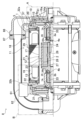
이하, 본 발명의 실시형태에 관련된 캔드 모터 펌프의 베어링 구조에 대해, 도면을 참조하면서 설명한다. 도 1 ∼ 도 4 에 나타내는 바와 같이, 캔드 모터 펌프의 베어링 구조 (1) 는, 캔드 모터 펌프 (8) 에 포함되는, 회전축 (2), 베어링 (3a, 3b), 피베어링 지지 부재 (4a, 4b), 임펠러 (6a, 6b), 탄성 구조 (7) 등으로 구성된다.Hereinafter, the bearing structure of the canned motor pump according to the embodiment of the present invention will be described with reference to the drawings. 1 to 4, the bearing structure 1 of the canned motor pump includes a rotating
캔드 모터 펌프 (8) 는, 도 1 에 나타내는 바와 같이, 모터부 (11) 와, 모터부 (11) 에 의해 구동되는 펌프부 (31) 를 구비한다. 모터부 (11) 는, 마그넷 (27) 을 가진 로터 (12) 와, 로터 (12) 외주의 스테이터 (13) 로 이루어지는 캔드 모터이며, 로터 (12) 가 고정된 회전축 (2) 은, 케이싱측 베어링 하우징 (32a, 32b) 에 장착된 베어링 (3a, 3b) 에 슬리브 (25) 를 개재하여 지지되어 있다. 펌프부 (31) 는, 회전축 (2) 에 고정된 임펠러 (6a, 6b) 와, 임펠러 (6a, 6b) 를 수용하는 임펠러 수용 공간 (14a, 14b) 을 갖는 펌프 케이싱 (16a, 16b) 을 구비한다. 모터부 (11) 의 로터 (12) 는 스테이터 캔 (9) 의 내측에 수용되어 있다. 모터부 (11) 의 스테이터 (13) 는 스테이터 캔 (9) 내의 로터 (12) 에 대응하는 위치에 있어서, 스테이터 캔 (9) 의 외주면 (17) 과 원통상의 모터 프레임 (18) 의 내주면 (19) 의 사이에 수용되어 있다. 모터 프레임 (18) 은, 스테이터 캔 (9) 을 내포하고 있다. 스테이터 캔 (9) 과, 모터 프레임 (18) 의 양단에 형성된 스테이터 측판 (10) 은 용접으로 밀봉 접속되어 있다. 모터 프레임 (18) 과, 모터 프레임 (18) 의 양단에 형성된 스테이터 측판 (10) 은 O 링 (5) 으로 시일됨과 함께, 부분 용접됨으로써 밀봉 접속되어 있다. 스테이터 측판 (10) 과 케이싱측 베어링 하우징 (32a, 32b) 은, 스테이터 측판 (10) 의 양단에 배치 형성된 O 링 (15) 으로 내부 공간 (66) 을 봉지하고 있다. 펌프 케이싱 (16a, 16b) 과 케이싱측 베어링 하우징 (32a, 32b) 은, 케이싱측 베어링 하우징 (32a, 32b) 의 양단에 배치 형성된 O 링 (20) 으로 임펠러 수용 공간 (14a, 14b) 을 봉지하고 있다. 또한, 베어링 (3a, 3b) 의 내주면과 슬리브 (25) 의 사이에는 미소 간극이 형성되어 있기 때문에 베어링 (3a, 3b) 은, 축선에 대해 미소 각도 경사지는 것이 가능하게 되어 있다. 이하, 펌프 케이싱 (16a) 을「제 1 펌프 케이싱 (16a)」이라고 하고, 펌프 케이싱 (16b) 을「제 2 펌프 케이싱 (16b)」이라고 한다.As shown in FIG. 1 , the
또, 스테이터 캔 (9) 의 외주면 (17) 상으로서, 스테이터 코어 (21) 가 존재하지 않는 부분은, 서포트 캔 (22) 에 덮여 있다. 서포트 캔 (22) 은, 스테이터 캔 (9) 의 외주면 (17) 을 따른 원통 형상을 갖는다.Additionally, the portion on the outer
모터부 (11) 는, 로터 (12) 와 스테이터 (13) 를 구비한다. 로터 (12) 는, 로터 캔 (23), 로터 측판 (24), 로터 본체 (26), 마그넷 (27), 요크 (28) 등을 포함하여 구성되어 있다. 로터 (12) 는, 회전축 (2) 과 일체로 회전하도록 회전축 (2) 에 고정되어 있다. 회전축 (2) 은, 케이싱측 베어링 하우징 (32a, 32b) 에 장착된 베어링 (3a, 3b) 에 슬리브 (25) 를 개재하여 지지되어 있다. 로터 (12) 는, 회전축 (2) 에 대해 고정된 로터 본체 (26) 와, 로터 본체 (26) 에 지지된 요크 (28), 마그넷 (27), 로터 측판 (24), 로터 캔 (23) 을 구비한다. 로터 캔 (23) 은, 로터 본체 (26) 및 로터 측판 (24) 과 용접에 의해 접합되어 있고, 마그넷 (27) 과 요크 (28) 가 밀봉되어 있다. 로터 (12) 는, 캔드 모터 펌프 (8) 에 있어서의 스테이터 캔 (9) 의 내측에 수용되어 있다.The
스테이터 (13) 는, 전자 코일 (29) 등으로 구성되어 있고, 스테이터 (13) 에 구동 전류가 공급되면, 로터 (12) 및 회전축 (2) 이 회전 구동한다.The
회전축 (2) 은, 모터부 (11) 의 로터 (12) 가 고정되어 있고, 모터부 (11) 의 로터 (12) 와 일체로 회전한다.The
베어링 (3a, 3b) 은, 도 1 ∼ 도 4 에 나타내는 바와 같이, 펌프부 (31) 에 형성된 케이싱측 베어링 하우징 (32a, 32b) 에 탄성 박판재 (33) 를 개재하여 끼워넣어져 있다. 베어링 (3a, 3b) 은, 회전축 (2) 을 축방향과 수직인 방향으로 자유롭게 회전할 수 있도록 지지한다. 베어링 (3a, 3b) 은 원통상이다. 베어링 (3a, 3b) 에는, 축방향 단면 (34) 에 반경 방향으로 연장되는 홈 (76) 이 형성되고, 내주벽 (36) 에 나선상의 홈 (74) 이 형성되어 있다. 어느 홈 (74, 76) 도 액체를 흘리기 위해서 형성되어 있다. 베어링 (3a, 3b) 의 재질로서, 예를 들어, 내열성, 내구성이 우수한 SiC (실리콘 탄화규소) 가 사용된다.As shown in FIGS. 1 to 4, the
본 실시형태에서는, 베어링 (3a, 3b) 은, 회전축 (2) 의 일부재인 슬리브 (25) 의 외주에 배치 형성되어 있다. 슬리브 (25) 의 재질로서도, 베어링 (3a, 3b) 과 마찬가지로, 내열성, 내구성이 우수한 재질이 사용된다.In this embodiment, the
베어링 (3a, 3b) 은, 회전축 (2) 의 축방향에 있어서 모터부 (11) 의 로터 (12) 의 양측에 형성되어 있다. 이하, 베어링 (3a) 을「제 1 베어링 (3a)」이라고 하고, 베어링 (3b) 을「제 2 베어링 (3b)」이라고 한다.
케이싱측 베어링 하우징 (32a, 32b) 에는, 베어링 (3a, 3b) 이 끼워넣어져 있다. 케이싱측 베어링 하우징 (32a, 32b) 은 펌프부 (31) 에 형성되어 있다.
케이싱측 베어링 하우징 (32a, 32b) 은, 회전축 (2) 의 축방향에 있어서 모터부 (11) 의 로터 (12) 의 양측에 형성되어 있다. 이하, 2 개의 케이싱측 하우징 (32) 을, 각각「제 1 케이싱측 베어링 하우징 (32a)」과「제 2 케이싱측 베어링 하우징 (32b)」이라고 한다.The casing
탄성 박판재 (33) 로서 본 실시형태에서는, 톨러런스 링이 사용되고 있다. 베어링 (3a, 3b) 이 탄성 박판재 (33) 를 개재하여 케이싱측 베어링 하우징 (32a, 32b) 에 끼워넣어져 있기 때문에, 베어링 (3a, 3b) 의 케이싱측 베어링 하우징 (32a, 32b) 에 대한 덜걱거림이 방지되고, 케이싱측 베어링 하우징 (32a, 32b) 과 베어링 (3a, 3b) 의 사이에 있어서의 열팽창 계수의 차가 흡수된다.In this embodiment, a tolerance ring is used as the elastic
회전축 (2) 및 로터 (12) 에는, 피베어링 지지 부재 (4a, 4b) 를 수용하는 피베어링 지지 부재용 하우징 (38a, 38b) 이 형성되어 있다. 피베어링 지지 부재 (4a, 4b) 는, 피베어링 지지 부재용 탄성 박판재 (35) 를 개재하여, 피베어링 지지 부재용 하우징 (38a, 38b) 에 끼워넣어져 있다. 본 실시형태에서는, 피베어링 지지 부재용 탄성 박판재 (35) 에도 톨러런스 링이 사용되고 있다. 피베어링 지지 부재용 하우징 (38a, 38b) 이 회전축 (2) 에 대해 축방향으로 상대적으로 고정되어 있다. 피베어링 지지 부재 (4a, 4b) 는 피베어링 지지 부재용 하우징 (38a, 38b) 을 개재하여 회전축 (2) 에 대해 장착되어 있다. 그 때문에, 회전축 (2) 은, 피베어링 지지 부재 (4a, 4b) 및 피베어링 지지 부재용 하우징 (38a, 38b) 을 개재하여 축방향으로 베어링 (3a, 3b) 에 지지된다. 또한, 피베어링 지지 부재 (4a, 4b) 의 내주면과 피베어링 지지 부재용 하우징 (38a, 38b) 의 사이에는 소정 치수의 간극이 형성되어 있고, 피베어링 지지 부재 (4a, 4b) 는 축선에 대해 미소 각도 경사 가능하게 되어 있다.On the
피베어링 지지 부재 (4a, 4b) 도 회전축 (2) 의 축방향에 있어서 모터부 (11) 의 로터 (12) 의 양측에 형성되어 있다. 구체적으로는, 피베어링 지지 부재 (4a, 4b) 는, 모터부 (11) 의 로터 (12) 와 베어링 (3a, 3b) 의 사이에 있어서 회전축 (2) 에 대해 장착되고, 베어링 (3a, 3b) 에 의해 자유롭게 회전할 수 있도록 축방향으로 지지되어 있다. 피베어링 지지 부재 (4a, 4b) 의 재질로서 예를 들어 내열성, 내구성이 우수한 SiC 가 사용된다.
이하, 제 1 베어링 (3a) 에 지지되는 피베어링 지지 부재 (4a) 를「제 1 피베어링 지지 부재 (4a)」라고 하고, 제 2 베어링 (3b) 에 지지되는 피베어링 지지 부재 (4b) 를「제 2 피베어링 지지 부재 (4b)」라고 한다.Hereinafter, the bearing
임펠러 (6a, 6b) 는, 회전축 (2) 과 일체로 회전한다. 도 2 및 도 4 에 나타내는 바와 같이, 임펠러 (6a, 6b) 는, 회전축 (2) 에 고정된 원통상의 임펠러 보스부 (39a, 39b) 와, 임펠러 보스부 (39a, 39b) 에 접속된 원환판상의 임펠러 날개부 (45a, 45b) 를 구비하고 있다. 임펠러 보스부 (39a, 39b) 는, 원통상으로서 임펠러 보스부 (39a, 39b) 를 회전축 (2) 에 고정시키는 회전축 고정부 (47) 와, 회전축 고정부 (47) 의 외주면 위로부터 회전축 고정부 (47) 의 반경 방향으로 연장된 원환판상으로서 임펠러 날개부 (45a, 45b) 와 접속되는 임펠러 날개 접속부 (48) 를 갖는다. 임펠러 보스부 (39a, 39b) 는, 임펠러 날개 접속부 (48) 에 있어서 임펠러 날개부 (45a, 45b) 의 회전 중심측 단부 (46) 와 접속되어 있다. 임펠러 보스부 (39a, 39b) 의 임펠러 날개 접속부 (48) 에는, 축방향으로 관통된 임펠러 보스부 관통공 (49a, 49b) 이 형성되어 있다. 이 임펠러 보스부 관통공 (49a, 49b) 에는, 스테이터 캔 (9) 측으로부터 환류하는 액체가 통과한다. 또 임펠러 보스부 (39a, 39b) 의 임펠러 날개 접속부 (48) 에는, 액체의 역류를 방지하는 스테이터 캔 (9) 측으로 연장된 원환상의 임펠러 보스부 돌기편 (51a, 51b) 이 형성되어 있다. 임펠러 보스부 돌기편 (51a, 51b) 은 펌프 케이싱 (16a, 16b) 의 내벽면 (52) 에 형성된 원환상의 오목부 (53a, 53b) 에 삽입되어 있다.The
본 실시형태에 있어서의 캔드 모터 펌프 (8) 에서는, 임펠러 (6a, 6b) 가 스테이터 캔 (9) 의 축방향 양단에 1 개씩 형성되어 있다. 이하, 임펠러 (6a) 를「제 1 임펠러 (6a)」라고 하고, 임펠러 (6b) 를「제 2 임펠러 (6b)」라고 한다.In the can motor pump 8 in this embodiment, one
제 1 임펠러 (6a) 가 수용되어 있는 제 1 펌프 케이싱 (16a) 의 측면에는, 제 1 유입구 (56) 가 형성되어 있다. 또 제 1 펌프 케이싱 (16a) 의 상면에는, 제 1 펌프 케이싱 (16a) 내에 유입된 액체를 제 2 펌프 케이싱 (16b) 에 보내는 송액구 (57) 가 형성되어 있다.A
제 1 케이싱측 베어링 하우징 (32a) 은 제 1 임펠러 수용 공간 (14a) 과 스테이터 캔 (9) 의 내부 공간 (66) 을 연통하는 제 1 연통로 (67) 를 갖는다. 제 1 연통로 (67) 의 제 1 연통로 개구 (64) 는, 제 1 임펠러 수용 공간 (14a) 의 스테이터 캔 (9) 측의 벽면 (63) 으로서, 제 1 임펠러 보스부 돌기편 (51a) 보다 회전축 (2) 에 가까운 위치에서 제 1 임펠러 보스부 관통공 (49a) 의 근방에 형성된다.The first casing
제 1 케이싱측 베어링 하우징 (32a) 은, 제 1 임펠러 수용 공간 (14a) 을 제 1 펌프 케이싱 (16a) 과 함께 형성한다. 제 1 케이싱측 베어링 하우징 (32a) 은, 제 1 임펠러 수용 공간 (14a) 을 형성하는 스테이터 캔 (9) 측의 벽면 (63) 에 제 1 오목부 (53a) 를 갖는다. 제 1 오목부 (53a) 에는, 제 1 임펠러 보스부 (39a) 에 형성된 제 1 임펠러 보스부 돌기편 (51a) 이 삽입된다.The first casing
또 제 1 임펠러 날개부 (45a) 에는, 회전축 (2) 과 동축 중심이 되는 원통상의 제 1 폐색판 (78) 이 형성되어 있다. 제 1 폐색판 (78) 은, 회전축 (2) 의 축방향에서 제 1 유입구 (56) 의 방향으로 연장되고, 그 외주면과 제 1 펌프 케이싱 (16a) 에 있어서의 제 1 유입구 (56) 의 내벽 (77) 과의 간극을 작게 하고 있다. 제 1 폐색판 (78) 은, 제 1 임펠러 날개부 (45a) 에 있어서의 제 1 폐색판 (78) 측의 외벽 (79) 과 제 1 펌프 케이싱 (16a) 의 내벽 (54) 으로 형성되는 공간과 제 1 유입구 (56) 에 있어서의 공간의 사이를 폐색한다.Additionally, a cylindrical
타방의 임펠러인 제 2 임펠러 (6b) 는, 도 4 에 나타내는 바와 같이, 회전축 (2) 에 고정된 제 2 임펠러 보스부 (39b) 와, 제 2 임펠러 보스부 (39b) 에 접속된 제 2 임펠러 날개부 (45b) 를 구비하고 있다. 제 2 임펠러 보스부 (39b) 에는, 축방향으로서 스테이터 캔 (9) 측방향으로 연장된 원환상의 제 2 임펠러 보스부 돌기편 (51b) 이 형성되어 있다.As shown in FIG. 4, the
제 2 임펠러 (6b) 가 수용되어 있는 제 2 펌프 케이싱 (16b) 의 측면에는, 제 2 유입구 (58) 가 형성되어 있다. 제 2 유입구 (58) 는, 회전축 (2) 과 동축 중심축을 갖는 원통상으로서, 제 1 임펠러 (6a) 로부터 보내져 온 액체를 유입시킨다. 또 제 2 펌프 케이싱 (16b) 의 상면측에는, 제 2 펌프 케이싱 (16b) 내에 유입된 액체를 제 2 펌프 케이싱 (16b) 밖으로 토출하는 토출구 (61) 가 형성되어 있다.A
제 2 케이싱측 베어링 하우징 (32b) 은, 제 2 임펠러 수용 공간 (14b) 과 스테이터 캔 (9) 의 내부 공간 (66) 을 연통하는 제 2 연통로 (71) 를 갖는다. 제 2 연통로 (71) 의 제 2 연통로 개구 (69) 는, 제 2 임펠러 수용 공간 (14b) 의 스테이터 캔 (9) 측의 벽면 (68) 으로서, 제 2 임펠러 보스부 돌기편 (51b) 보다 회전축 (2) 에 가까운 위치에서 제 2 임펠러 보스부 관통공 (49b) 의 근방에 형성된다.The second casing side bearing housing (32b) has a second communication path (71) that communicates the second impeller accommodation space (14b) with the internal space (66) of the stator can (9). The second
제 2 케이싱측 베어링 하우징 (32b) 은, 제 2 임펠러 수용 공간 (14b) 을 제 2 펌프 케이싱 (16b) 과 함께 형성한다. 제 2 케이싱측 베어링 하우징 (32b) 은, 제 2 임펠러 수용 공간 (14b) 을 형성하는 스테이터 캔 (9) 측의 벽면 (68) 에 제 2 오목부 (53b) 를 갖는다. 제 2 오목부 (53b) 에는, 제 2 임펠러 보스부 (39b) 에 형성된 제 2 임펠러 보스부 돌기편 (51b) 이 삽입된다.The second casing
또 제 2 임펠러 날개부 (45b) 에는, 회전축 (2) 과 동축 중심이 되는 원통상의 제 2 폐색판 (82) 이 형성되어 있다. 제 2 폐색판 (82) 은, 회전축 (2) 의 축방향에서 제 2 유입구 (58) 의 방향으로 연장되고, 그 외주면과 제 2 펌프 케이싱 (16b) 에 있어서의 제 2 유입구 (58) 의 내벽 (81) 과의 간극을 작게 하고 있다. 제 2 폐색판 (82) 은, 제 2 임펠러 날개부 (45b) 에 있어서의 제 2 폐색판 (82) 측의 외벽 (83) 과 제 2 펌프 케이싱 (16b) 의 내벽 (59) 으로 형성되는 공간과 제 2 유입구 (58) 에 있어서의 공간의 사이를 폐색한다.Additionally, a cylindrical
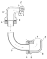
제 1 펌프 케이싱 (16a) 과 제 2 펌프 케이싱 (16b) 은, 제 1 임펠러 (6a) 로부터 제 2 임펠러 (6b) 에 액체를 보낼 때의 유로를 형성하는 연결 파이프 (62) 에 의해 연결되어 있다. 연결 파이프 (62) 는, 모터 프레임 (18) 의 외측을 지나, 제 1 펌프 케이싱 (16a) 의 송액구 (57) 로부터 토출되는 액체를 제 2 펌프 케이싱 (16b) 의 제 2 유입구 (58) 에 보낸다.The
본 실시형태에 있어서의 캔드 모터 펌프 (8) 에 있어서는, 도 3 및 도 4 에 나타내는 바와 같이, 임펠러 (6a, 6b) 의 회전에 의해 반송되는 액체의 일부가 회전축 (2) 과 베어링 (3a, 3b) 의 사이를 이점쇄선의 화살표로 나타내는 바와 같이 흐른다.In the can motor pump 8 in this embodiment, as shown in Figs. 3 and 4, a part of the liquid conveyed by rotation of the
제 1 유입구 (56) 로부터 제 1 펌프 케이싱 (16a) 내로 유입된 액체는, 제 1 임펠러 (6a) 의 회전력에 의해 제 1 임펠러 (6a) 의 제 1 임펠러 날개 내 유로 (72) 를 지나, 연결 파이프 (62) 내를 통과하여 제 2 유입구 (58) 로부터 제 2 펌프 케이싱 (16b) 내로 유입된다.The liquid flowing into the first pump casing (16a) from the first inlet (56) passes through the flow path (72) within the first impeller blade of the first impeller (6a) by the rotational force of the first impeller (6a), and is connected. It passes through the
제 2 펌프 케이싱 (16b) 내로 유입된 액체는, 2 방향으로 분기되고, 분기된 일방의 액체는 제 2 임펠러 (6b) 의 회전력에 의해 제 2 임펠러 (6b) 의 제 2 임펠러 날개 내 유로 (73) 를 지나, 토출구 (61) 로부터 제 2 펌프 케이싱 (16b) 밖으로 토출된다. 분기된 타방의 액체는, 제 2 임펠러 (6b) 의 제 2 임펠러 보스부 관통공 (49b) 을 통과하여 스테이터 캔 (9) 내로 보내진다.The liquid flowing into the second pump casing (16b) branches in two directions, and one branched liquid flows into the flow path (73) within the second impeller blade of the second impeller (6b) by the rotational force of the second impeller (6b). ), and is discharged out of the second pump casing (16b) from the discharge port (61). The other branched liquid passes through the second impeller boss through
제 2 펌프 케이싱 (16b) 으로부터 스테이터 캔 (9) 내로 보내진 액체는, 나아가 2 방향으로 분기된다. 분기된 액체의 일방은, 제 2 펌프 케이싱 (16b) 에 형성된 제 2 연통로 (71) 를 통과하여, 스테이터 캔 (9) 과 로터 (12) 의 사이의 공간을 제 1 베어링 (3a) 의 방향으로 향하여 통과한다. 분기된 액체의 타방은, 회전축 (2) 의 슬리브 (25) 와 제 2 베어링 (3b) 의 사이를 통과한다.The liquid sent from the
회전축 (2) 의 슬리브 (25) 와 제 2 베어링 (3b) 의 사이를 통과한 액체는, 제 2 베어링 (3b) 과 제 2 피베어링 지지 부재 (4b) 의 사이를 통과하여, 스테이터 캔 (9) 과 로터 (12) 의 사이의 공간을 제 1 베어링 (3a) 의 방향으로 향하여 통과한다. 액체가 회전축 (2) 의 슬리브 (25) 와 제 2 베어링 (3b) 의 사이를 통과하는 경우 및 액체가 제 2 베어링 (3b) 과 제 2 피베어링 지지 부재 (4b) 의 사이를 통과하는 경우, 액체는 주로 제 2 베어링 (3b) 에 형성된 홈 (76, 74) 을 통과한다. 액체가 회전축 (2) 의 슬리브 (25) 와 제 2 베어링 (3b) 의 사이 및 제 2 베어링 (3b) 과 제 2 피베어링 지지 부재 (4b) 의 사이를 통과하는 경우, 액체는, 회전축 (2) 의 슬리브 (25) 와 제 2 베어링 (3b) 의 사이 및 제 2 베어링 (3b) 과 제 2 피베어링 지지 부재 (4b) 의 사이에 있어서의 윤활제가 된다.The liquid that has passed between the
스테이터 캔 (9) 과 로터 (12) 의 사이의 공간을 통과한 액체는, 2 방향으로 분기된다. 일방의 액체는, 제 1 펌프 케이싱 (16a) 의 제 1 연통로 (67) 및 제 1 임펠러 보스부 (39a) 의 제 1 임펠러 보스부 관통공 (49a) 을 통과하여 제 1 임펠러 (6a) 의 제 1 임펠러 날개 내 유로 (72) 에 들어간다. 타방의 액체는, 제 1 베어링 (3a) 과 제 1 피베어링 지지 부재 (4a) 의 사이를 통과하여, 제 1 베어링 (3a) 과 회전축 (2) 의 슬리브 (25) 의 사이를 통과한다. 액체가 제 1 베어링 (3a) 과 제 1 피베어링 지지 부재 (4a) 의 사이를 통과하는 경우, 및 액체가 제 1 베어링 (3a) 과 회전축 (2) 의 슬리브 (25) 의 사이를 통과하는 경우, 액체는 주로 제 1 베어링 (3a) 에 형성된 홈 (74, 76) 을 통과한다. 액체가 제 1 베어링 (3a) 과 제 1 피베어링 지지 부재 (4a) 의 사이를 통과하는 경우, 및 제 1 베어링 (3a) 과 회전축 (2) 의 슬리브 (25) 의 사이를 통과하는 경우, 액체는, 제 1 베어링 (3a) 과 제 1 피베어링 지지 부재 (4a) 의 사이, 및 제 1 베어링 (3a) 과 회전축 (2) 의 슬리브 (25) 의 사이에 있어서의 윤활제가 된다. 제 1 베어링 (3a) 과 회전축 (2) 의 슬리브 (25) 의 사이를 통과한 액체는, 제 1 임펠러 보스부 (39a) 의 제 1 임펠러 보스부 관통공 (49a) 을 통과하여 제 1 임펠러 (6a) 의 제 1 임펠러 날개 내 유로 (72) 에 들어간다.The liquid that passes through the space between the stator can 9 and the
제 1 펌프 케이싱 (16a) 과 연결 파이프 (62) 는, 도 5 에 나타내는 바와 같이, 제 1 펌프 케이싱 (16a) 상면측의 송액구 (57) 의 2 차측에 형성된 제 1 토출 유로 (84) 를 개재하여 접속되어 있다. 제 1 토출 유로 (84) 와 연결 파이프 (62) 는, 서로 대향하는 단부의 각각에 형성된 플랜지 (86, 87) 끼리를 볼트로 체결하여 접속되어 있다.As shown in FIG. 5, the
제 2 펌프 케이싱 (16b) 과 연결 파이프 (62) 는, 제 2 펌프 케이싱 (16b) 에 있어서의 제 2 유입구 (58) 의 1 차측에 형성된 제 2 흡입 유로 (88) 를 개재하여 접속되어 있다. 제 2 흡입 유로 (88) 와 연결 파이프 (62) 는, 서로 대향하는 단부의 각각에 형성된 플랜지 (89, 91) 끼리를 볼트로 체결하여 접속되어 있다.The
탄성 구조 (7) (7A, 7B 및 7C) 는, 도 6, 도 7 및 도 8 에 나타내는 바와 같이, 베어링 (3a, 3b) 이 피베어링 지지 부재 (4a, 4b) 에 의해 모터부 (11) 의 로터 (12) 와 반대측으로 압압되었을 경우에, 베어링 (3a, 3b) 및 피베어링 지지 부재 (4a, 4b) 의 일방 또는 쌍방에 대해 축방향으로 탄성 반력을 부여하는 것이다.As shown in Figs. 6, 7, and 8, the elastic structure 7 (7A, 7B, and 7C) is such that the
회전축 (2) 은, 축방향의 압력차에 의해 제 1 임펠러 (6a) 측으로 유격분만큼 이동하고, 베어링 (3a, 3b) 과 피베어링 지지 부재 (4a, 4b) 가 서로 축방향으로 압압한다. 이 때, 피베어링 지지 부재용 하우징 (38a, 38b) 의 내주면 및 케이싱측 베어링 하우징 (32a, 32b) 의 내주면에 치수 오차가 있어도, 탄성 구조 (7) 가 형성되어 있으므로, 베어링 (3a, 3b) 및/또는 피베어링 지지 부재 (4a, 4b) 는, 서로 대향하는 면이 면접촉하도록, 축방향에 대해 미소각 경동 (傾動) 하면서 서로 맞닿는다. 이와 같이, 베어링 (3a, 3b) 과 피베어링 지지 부재 (4a, 4b) 가 면접촉함으로써, 베어링 (3a, 3b) 이 피베어링 지지 부재 (4a, 4b) 에 국부 접촉함으로써 발생하는 마모가 방지된다.The
도 6 은, 탄성 구조 (7B) 가, 베어링 (3a) 의 모터부 (11) 의 로터 (12) 와 반대측과, 케이싱측 베어링 하우징 (32a) 과의 사이에 형성된 탄성체로 구성되어 있는 예, 및, 탄성 구조 (7B) 가, 피베어링 지지 부재용 하우징 (38a) 과, 피베어링 지지 부재 (4a) 의 모터부 (11) 의 로터 (12) 측과의 사이에 형성된 예를 나타낸다. 동 도면에 나타내는 탄성체는, 코일 스프링이다. 코일 스프링은, 그 직경이, 베어링 (3a) 및 피베어링 지지 부재 (4a) 의 직경 방향의 두께와 동일 또는 그들의 두께보다 작은 것이다. 또, 코일 스프링은, 베어링 (3a) 및 피베어링 지지 부재 (4a) 의 각각의 둘레 방향으로 일정한 간격을 두고 복수 형성되어 있다. 또한, 도 6 은, 제 1 임펠러 (6a) 측의 탄성 구조 (7B) 만을 나타내고, 제 2 임펠러 (6b) 측의 탄성 구조 (7B) 의 도시를 생략하고 있다. 제 2 임펠러 (6b) 측의 탄성 구조 (7B) (도시 생략) 는, 로터 (12) 를 중심으로 하여, 제 1 임펠러 (6a) 측의 탄성 구조 (7B) 와 축방향으로 대칭인 구조를 갖는다.Figure 6 shows an example in which the
도 8 에 나타내는 탄성 구조 (7C) 는, 도 6 에 나타내는 예에 있어서, 탄성 구조 (7B) 를 이루는 복수의 코일 스프링을 1 개의 코일 스프링으로 치환한 것이다. 탄성 구조 (7C) 를 이루는 코일 스프링은, 회전축 (2) 과 동심 위치에 배치되어 있다. 도 8 의 코일 스프링은, 베어링 (3a, 3b) 및 피베어링 지지 부재 (4a, 4b) 의 각각의 단면의 직경 방향 중앙 근방을 압압하고 있다. 또한, 도 8 은, 제 1 임펠러 (6a) 측의 탄성 구조 (7C) 만을 나타내고, 제 2 임펠러 (6b) 측의 탄성 구조 (7C) 의 도시를 생략하고 있다. 제 2 임펠러 (6b) 측의 탄성 구조 (7C) (도시 생략) 는, 로터 (12) 를 중심으로 하여, 제 1 임펠러 (6a) 측의 탄성 구조 (7C) 와 축방향으로 대칭인 구조를 갖는다.The
또한, 탄성 구조 (7B, 7C) 를 이루는 코일 스프링 대신에, 스프링 와셔, 접시 스프링 와셔, 웨이브 와셔 등도 채용할 수 있다.Additionally, instead of the coil spring forming the elastic structure (7B, 7C), a spring washer, disc spring washer, wave washer, etc. can also be employed.
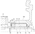
도 7 은, 탄성 구조 (7A) 가, 베어링 (3a) 의 모터부 (11) 의 로터 (12) 와 반대측과, 케이싱측 베어링 하우징 (32a) 과의 사이에 판재 (92) 가 형성되고, 케이싱측 베어링 하우징 (32a) 이 판재 (92) 의 베어링 (3a) 과 반대측의 면의 일부만을 축방향으로 지지함으로써, 베어링 (3a) 에 대해 축방향으로 탄성 반력을 부여하는 것이다. 판재 (92) 에는 예를 들어 금속제의 얇은 판, 예를 들어 금속제 와셔 등을 사용할 수 있다. 이 경우, 케이싱측 베어링 하우징 (32a) 과 판재 (92) 의 사이에 베어링측 간극 (93) 이 형성된다. 또한, 도 7 에서는 판재 (92) 의 구부러진 정도 그리고 베어링 (3a) 및 피베어링 지지 부재 (4a) 의 경사를 강조하여 표현하고 있다. 또한, 도 7 은, 제 1 임펠러 (6a) 측의 탄성 구조 (7A) 만을 나타내고 있다. 제 2 임펠러 (6b) 측의 탄성 구조 (7A) 는, 도 2 에 나타내는 바와 같이, 로터 (12) 를 중심으로 하여, 제 1 임펠러 (6a) 측의 탄성 구조 (7A) 와 축방향으로 대칭인 구조를 갖는다.7 shows that the
본 실시형태에서는, 베어링측 간극 (93) 은, 판재 (92) 의 내경측의 편면측에 형성되고, 판재 (92) 의 외경측은, 베어링 (3a, 3b) 과 케이싱측 베어링 하우징 (32a, 32b) 사이에 끼워진다. 판재 (92) 의 내경측의 편면측에만 베어링측 간극 (93) 이 형성됨으로써, 베어링 (3a, 3b) 이 회전축 (2) 에 대해 경사진 경우, 판재 (92) 가 베어링측 간극 (93) 측으로 휘어 탄성력을 발생시킨다.In this embodiment, the bearing
또 도 7 에서는, 가일층의 탄성 구조 (7D) 로서, 피베어링 지지 부재 (4a) 의 모터부 (11) 의 로터 (12) 측과, 피베어링 지지 부재용 하우징 (38a) 과의 사이에 판재 (92) 가 형성되고, 피베어링 지지 부재용 하우징 (38a) 이 판재 (92) 의 피베어링 지지 부재 (4a) 와 반대측의 면의 일부만을 축방향으로 지지함으로써, 피베어링 지지 부재 (4a) 에 대해 축방향으로 탄성 반력을 부여하는 것을 나타낸다. 여기서도, 판재 (92) 에는 예를 들어 금속제의 얇은 판, 예를 들어 금속제 와셔 등을 사용할 수 있고, 피베어링 지지 부재용 하우징 (38a) 에는 판재 (92) 와의 사이에 피베어링 지지 부재측 간극 (94) 이 형성된다. 또한, 도 7 은, 제 1 임펠러 (6a) 측의 탄성 구조 (7D) 만을 나타내고 있다. 제 2 임펠러 (6b) 측의 탄성 구조 (7D) 는, 도 4 에 나타내는 바와 같이, 로터 (12) 를 중심으로 하여, 제 1 임펠러 (6a) 측의 탄성 구조 (7D) 와 축방향으로 대칭인 구조를 갖는다.Also, in Fig. 7, as an additional layer of
본 실시형태에서는, 피베어링 지지 부재측 간극 (94) 은, 판재 (92) 의 외경측의 편면측에 형성되고, 판재 (92) 의 내경측은, 피베어링 지지 부재 (4a, 4b) 와 피베어링 지지 부재용 하우징 (38a, 38b) 사이에 끼워진다. 판재 (92) 의 외경측의 편면측에만 피베어링 지지 부재측 간극 (94) 이 형성됨으로써, 피베어링 지지 부재 (4a, 4b) 가 회전축 (2) 에 대해 경사진 경우, 판재 (92) 가 피베어링 지지 부재측 간극 (94) 측으로 휘어 탄성력을 발생시킨다.In this embodiment, the bearing support
도 9 는, 베어링 (3a) 과 피베어링 지지 부재 (4a) 가 회전축 (2) 에 대해 약간 기울어진 상태에서 면접촉하고 있는 상태를 나타내는 도면이다. 단, 판재 (92) 의 구부러진 정도만을 강조하여 표현하고, 베어링 (3a) 및 피베어링 지지 부재 (4a) 의 경사는 강조하지 않고 표현하고 있다.FIG. 9 is a diagram showing a state in which the
판재 (92) 는, 둘레 방향의 임의의 위치에서, 베어링측 간극 (93) 측 또는 피베어링 지지 부재측 간극 (94) 측으로 휘는 것이 가능하기 때문에, 베어링 (3a, 3b) 과 피베어링 지지 부재 (4a, 4b) 가 서로 면접촉하지 않는 상태에서 축방향으로 가압되면, 베어링 (3a, 3b) 과 피베어링 지지 부재 (4a, 4b) 는, 도 9 에 나타내는 바와 같이, 각각 축방향에 대해 경동함과 동시에, 판재 (92) 의 일부가 베어링측 간극 (93) 측 또는 피베어링 지지 부재측 간극 (94) 측으로 휘고, 그 결과, 베어링 (3a, 3b) 과 피베어링 지지 부재 (4a, 4b) 는, 서로 면접촉하게 된다. 또한, 도 9 에 나타내는 예에서는, 피베어링 지지 부재 (4a) 의 도면 중 상부의 외경측이 판재 (92) 를 피베어링 지지 부재측 간극 (94) 측으로 압압하고, 베어링 (3a) 의 도면 중 상부의 내경측이 판재 (92) 를 베어링측 간극 (93) 측으로 압압하고 있기 때문에, 각 판재 (92) 가 휘어져 있다.Since the
상기 실시형태의 변형예로서, 상기 실시형태에 있어서, 판재 (92) 는, 베어링 (3a, 3b) 과 케이싱측 베어링 하우징 (32a, 32b) 의 사이, 피베어링 지지 부재 (4a, 4b) 와 피베어링 지지 부재용 하우징 (38a, 38b) 의 사이의 어느 일방에만 형성되어도 된다.As a modification of the above embodiment, in the above embodiment, the
본 발명은, 그 정신이나 주지 또는 주요한 특징으로부터 일탈하는 일 없이, 다른 여러 형태로 실시할 수 있다. 그 때문에, 상기 서술한 실시형태는 모든 점에서 단순한 예시에 지나지 않고, 한정적으로 해석해서는 안 된다.The present invention can be implemented in various other forms without departing from its spirit, main principles, or main features. Therefore, the above-described embodiment is merely an example in all respects and should not be interpreted limitedly.
본 발명은, 예를 들어, 캔드 모터 펌프에 적용할 수 있다.The present invention can be applied to, for example, canned motor pumps.
1 : 캔드 모터 펌프의 베어링 구조
2 : 회전축
3a, 3b : 베어링
4a, 4b : 피베어링 지지 부재
6a, 6b : 임펠러
7A, 7B, 7C, 7D : 탄성 구조
8 : 캔드 모터 펌프
11 : 모터부
12 : 로터
31 : 펌프부
32a, 32b : 케이싱측 베어링 하우징
33 : 탄성 박판재
38a, 38b : 피베어링 지지 부재용 하우징
92 : 판재1: Bearing structure of canned motor pump
2: rotation axis
3a, 3b: Bearing
4a, 4b: bearing support member
6a, 6b: Impeller
7A, 7B, 7C, 7D: Elastic structure
8: Canned motor pump
11: motor part
12: rotor
31: pump part
32a, 32b: Casing side bearing housing
33: Elastic sheet material
38a, 38b: Housing for bearing support member
92: plate
Claims (5)
펌프부에 형성된 케이싱측 베어링 하우징에 탄성 박판재를 개재하여 끼워넣어져, 상기 회전축을 축방향과 수직인 방향으로 자유롭게 회전할 수 있도록 지지하는 베어링과,
상기 모터부의 로터와 상기 베어링의 사이에 있어서 상기 회전축에 대해 장착되어, 상기 베어링에 의해 자유롭게 회전할 수 있도록 축방향으로 지지되는 피베어링 지지 부재와,
상기 회전축과 일체로 회전하는 임펠러를 구비하고,
상기 임펠러의 회전에 의해 반송되는 액체의 일부가 상기 회전축과 상기 베어링의 사이를 흐르는 캔드 모터 펌프에 있어서,
상기 베어링이 상기 피베어링 지지 부재에 의해 상기 모터부의 로터와 반대측으로 압압되었을 경우에, 상기 베어링 및 상기 피베어링 지지 부재의 일방 또는 쌍방에 대해 축방향으로 탄성 반력을 부여하는 탄성 구조가 형성된 것을 특징으로 하는 캔드 모터 펌프의 베어링 구조.A rotating shaft that rotates integrally with the rotor of the motor unit,
A bearing that is inserted into the casing-side bearing housing formed in the pump unit through an elastic thin plate material and supports the rotation shaft so that it can freely rotate in a direction perpendicular to the axial direction;
a bearing support member mounted on the rotation axis between the rotor of the motor unit and the bearing and supported in the axial direction so as to rotate freely by the bearing;
Provided with an impeller that rotates integrally with the rotation shaft,
In the canned motor pump, a part of the liquid conveyed by rotation of the impeller flows between the rotation shaft and the bearing,
When the bearing is pressed against the rotor of the motor unit by the bearing support member, an elastic structure is formed that provides an elastic reaction force in the axial direction to one or both of the bearing and the bearing support member. Bearing structure of canned motor pump.
상기 탄성 구조는, 상기 베어링에 대해 축방향으로 상기 탄성 반력을 부여하는 것으로서, 상기 베어링의 상기 모터부의 로터와 반대측과, 상기 케이싱측 베어링 하우징과의 사이에 형성된 탄성체인 것을 특징으로 하는 캔드 모터 펌프의 베어링 구조.According to claim 1,
The elastic structure provides the elastic reaction force in the axial direction with respect to the bearing, and is an elastic body formed between a side of the bearing opposite to the rotor of the motor part and the bearing housing on the casing side. bearing structure.
상기 피베어링 지지 부재는, 피베어링 지지 부재용 하우징을 개재하여 상기 회전축에 대해 장착되어 있고,
상기 탄성 구조는, 상기 피베어링 지지 부재에 대해 축방향으로 상기 탄성 반력을 부여하는 것으로서, 상기 피베어링 지지 부재용 하우징과, 상기 피베어링 지지 부재의 상기 모터부의 로터측과의 사이에 형성된 탄성체인 것을 특징으로 하는 캔드 모터 펌프의 베어링 구조.According to claim 1,
The bearing support member is mounted with respect to the rotation shaft via a housing for the bearing support member,
The elastic structure provides the elastic reaction force in the axial direction with respect to the bearing support member, and is an elastic chain formed between the housing for the bearing support member and the rotor side of the motor portion of the bearing support member. Bearing structure of a canned motor pump, characterized in that.
상기 탄성 구조는,
상기 베어링의 상기 모터부의 로터와 반대측과, 상기 케이싱측 베어링 하우징과의 사이에 판재가 형성되고,
상기 케이싱측 베어링 하우징이 상기 판재의 상기 베어링과 반대측의 면의 일부만을 축방향으로 지지함으로써, 상기 베어링에 대해 축방향으로 상기 탄성 반력을 부여하는 것인 것을 특징으로 하는 캔드 모터 펌프의 베어링 구조.According to claim 1,
The elastic structure is,
A plate is formed between a side of the bearing opposite to the rotor of the motor section and the bearing housing on the casing side,
A bearing structure for a canned motor pump, wherein the casing-side bearing housing axially supports only a portion of a surface of the plate opposite to the bearing, thereby imparting the elastic reaction force to the bearing in the axial direction.
상기 피베어링 지지 부재는, 피베어링 지지 부재용 하우징을 개재하여 상기 회전축에 대해 축방향으로 고정되어 있고,
상기 탄성 구조는,
상기 피베어링 지지 부재의 상기 모터부의 로터측과, 상기 피베어링 지지 부재용 하우징과의 사이에 판재가 형성되고,
상기 피베어링 지지 부재용 하우징이 상기 판재의 상기 피베어링 지지 부재와 반대측의 면의 일부만을 축방향으로 지지함으로써, 상기 피베어링 지지 부재에 대해 축방향으로 상기 탄성 반력을 부여하는 것인 것을 특징으로 하는 캔드 모터 펌프의 베어링 구조.According to claim 1,
The bearing support member is axially fixed to the rotation axis via a housing for the bearing support member,
The elastic structure is,
A plate is formed between the rotor side of the motor portion of the bearing support member and the housing for the bearing support member,
Characterized in that the housing for the bearing support member provides the elastic reaction force to the bearing support member in the axial direction by supporting only a portion of the surface of the plate opposite to the bearing support member in the axial direction. Bearing structure of canned motor pump.
Applications Claiming Priority (3)
| Application Number | Priority Date | Filing Date | Title |
|---|---|---|---|
| JP2021094287 | 2021-06-04 | ||
| JPJP-P-2021-094287 | 2021-06-04 | ||
| PCT/JP2022/016912 WO2022254959A1 (en) | 2021-06-04 | 2022-03-31 | Canned-motor-pump bearing structure |
Publications (1)
| Publication Number | Publication Date |
|---|---|
| KR20240004667A true KR20240004667A (en) | 2024-01-11 |
Family
ID=84323118
Family Applications (1)
| Application Number | Title | Priority Date | Filing Date |
|---|---|---|---|
| KR1020237040864A KR20240004667A (en) | 2021-06-04 | 2022-03-31 | Bearing structure of canned motor pump |
Country Status (4)
| Country | Link |
|---|---|
| JP (1) | JP7525739B2 (en) |
| KR (1) | KR20240004667A (en) |
| CN (1) | CN117460892A (en) |
| WO (1) | WO2022254959A1 (en) |
Citations (1)
| Publication number | Priority date | Publication date | Assignee | Title |
|---|---|---|---|---|
| JP3897931B2 (en) | 1999-05-20 | 2007-03-28 | 株式会社荏原製作所 | Canned motor pump |
Family Cites Families (4)
| Publication number | Priority date | Publication date | Assignee | Title |
|---|---|---|---|---|
| JPH1169704A (en) * | 1997-08-21 | 1999-03-09 | Asmo Co Ltd | Bearing device for motor |
| JP2011032923A (en) * | 2009-07-31 | 2011-02-17 | Yamada Seisakusho Co Ltd | Water pump |
| DE102013208460A1 (en) | 2013-05-08 | 2014-11-13 | Ksb Aktiengesellschaft | Pump arrangement with a sliding bearing arrangement |
| KR20230107881A (en) | 2020-12-15 | 2023-07-18 | 산소덴키 가부시키가이샤 | cand motor pump |
-
2022
- 2022-03-31 JP JP2023525643A patent/JP7525739B2/en active Active
- 2022-03-31 KR KR1020237040864A patent/KR20240004667A/en unknown
- 2022-03-31 WO PCT/JP2022/016912 patent/WO2022254959A1/en active Application Filing
- 2022-03-31 CN CN202280039152.5A patent/CN117460892A/en active Pending
Patent Citations (1)
| Publication number | Priority date | Publication date | Assignee | Title |
|---|---|---|---|---|
| JP3897931B2 (en) | 1999-05-20 | 2007-03-28 | 株式会社荏原製作所 | Canned motor pump |
Also Published As
| Publication number | Publication date |
|---|---|
| JPWO2022254959A1 (en) | 2022-12-08 |
| CN117460892A (en) | 2024-01-26 |
| JP7525739B2 (en) | 2024-07-30 |
| WO2022254959A1 (en) | 2022-12-08 |
Similar Documents
| Publication | Publication Date | Title |
|---|---|---|
| US10253783B2 (en) | Pump arrangement comprising a plain bearing arrangement | |
| US10920787B2 (en) | Blower | |
| CN107835905B (en) | Bearing structure and supercharger | |
| US20150159666A1 (en) | Spherical Sleeve and Bushing Bearing for Centrifugal Pump Stage | |
| US11035403B2 (en) | Radial force support apparatus | |
| US6540474B2 (en) | Side-channel pump | |
| KR20240004667A (en) | Bearing structure of canned motor pump | |
| JP6934781B2 (en) | Multi-stage centrifugal fluid machine | |
| JP4078833B2 (en) | Double suction centrifugal pump | |
| US20100021282A1 (en) | Side-Channel Pump | |
| JP6863477B2 (en) | Electric motor and electric blower | |
| US6503049B2 (en) | Feed pump | |
| JP6559717B2 (en) | mechanical seal | |
| KR102512293B1 (en) | Motor assembly and manufacturing method thereof | |
| JP2006037918A (en) | Axial-flow pump | |
| KR102512292B1 (en) | Motor assembly and manufacturing method thereof | |
| CN111720355B (en) | Bearing structure of electric fluid pump | |
| JP2000240583A (en) | Electric motor | |
| KR20200034676A (en) | Motor | |
| EP4004372A1 (en) | Scroll pump | |
| JP4300529B2 (en) | Vane pump | |
| KR20240038771A (en) | Bearing structure of canned motor pump | |
| KR102124493B1 (en) | Motor assembly and manufacturing method thereof | |
| CN111271382B (en) | Rolling bearing fixing structure | |
| KR102410221B1 (en) | Motor assembly and manufacturing method thereof |