KR20230148928A - Actuator for driving zoom - Google Patents
Actuator for driving zoom Download PDFInfo
- Publication number
- KR20230148928A KR20230148928A KR1020220047917A KR20220047917A KR20230148928A KR 20230148928 A KR20230148928 A KR 20230148928A KR 1020220047917 A KR1020220047917 A KR 1020220047917A KR 20220047917 A KR20220047917 A KR 20220047917A KR 20230148928 A KR20230148928 A KR 20230148928A
- Authority
- KR
- South Korea
- Prior art keywords
- carrier
- optical axis
- support member
- actuator
- guiding space
- Prior art date
Links
- 230000003287 optical effect Effects 0.000 claims abstract description 51
- 239000000969 carrier Substances 0.000 claims description 19
- 238000000034 method Methods 0.000 claims description 11
- 238000010586 diagram Methods 0.000 description 13
- 230000008569 process Effects 0.000 description 4
- 230000008901 benefit Effects 0.000 description 3
- 238000002347 injection Methods 0.000 description 3
- 239000007924 injection Substances 0.000 description 3
- 239000000463 material Substances 0.000 description 3
- 101001045744 Sus scrofa Hepatocyte nuclear factor 1-beta Proteins 0.000 description 2
- 239000007769 metal material Substances 0.000 description 2
- 238000012986 modification Methods 0.000 description 2
- 230000004048 modification Effects 0.000 description 2
- 230000005355 Hall effect Effects 0.000 description 1
- 230000000712 assembly Effects 0.000 description 1
- 238000000429 assembly Methods 0.000 description 1
- 230000008859 change Effects 0.000 description 1
- 238000001514 detection method Methods 0.000 description 1
- 238000005516 engineering process Methods 0.000 description 1
- 230000007613 environmental effect Effects 0.000 description 1
- 239000011521 glass Substances 0.000 description 1
- 238000001746 injection moulding Methods 0.000 description 1
- 230000002452 interceptive effect Effects 0.000 description 1
- 239000002184 metal Substances 0.000 description 1
- 239000003607 modifier Substances 0.000 description 1
- 238000000465 moulding Methods 0.000 description 1
- 230000035939 shock Effects 0.000 description 1
- 230000006641 stabilisation Effects 0.000 description 1
- 238000011105 stabilization Methods 0.000 description 1
Images


Classifications
-
- G—PHYSICS
- G02—OPTICS
- G02B—OPTICAL ELEMENTS, SYSTEMS OR APPARATUS
- G02B7/00—Mountings, adjusting means, or light-tight connections, for optical elements
- G02B7/02—Mountings, adjusting means, or light-tight connections, for optical elements for lenses
- G02B7/04—Mountings, adjusting means, or light-tight connections, for optical elements for lenses with mechanism for focusing or varying magnification
- G02B7/09—Mountings, adjusting means, or light-tight connections, for optical elements for lenses with mechanism for focusing or varying magnification adapted for automatic focusing or varying magnification
-
- G—PHYSICS
- G02—OPTICS
- G02B—OPTICAL ELEMENTS, SYSTEMS OR APPARATUS
- G02B27/00—Optical systems or apparatus not provided for by any of the groups G02B1/00 - G02B26/00, G02B30/00
- G02B27/64—Imaging systems using optical elements for stabilisation of the lateral and angular position of the image
- G02B27/646—Imaging systems using optical elements for stabilisation of the lateral and angular position of the image compensating for small deviations, e.g. due to vibration or shake
-
- G—PHYSICS
- G02—OPTICS
- G02B—OPTICAL ELEMENTS, SYSTEMS OR APPARATUS
- G02B7/00—Mountings, adjusting means, or light-tight connections, for optical elements
- G02B7/02—Mountings, adjusting means, or light-tight connections, for optical elements for lenses
- G02B7/04—Mountings, adjusting means, or light-tight connections, for optical elements for lenses with mechanism for focusing or varying magnification
- G02B7/10—Mountings, adjusting means, or light-tight connections, for optical elements for lenses with mechanism for focusing or varying magnification by relative axial movement of several lenses, e.g. of varifocal objective lens
Abstract
본 발명에 의한 줌 구동용 액추에이터는 제1지지부재, 상기 제1지지부재의 일부분인 제1파트가 노출되도록 상기 제1지지부재가 인서트되어 성형되는 제1몸체부와, 광축을 기준으로 상기 제1파트의 반대편에 형성되는 제1가이딩공간을 포함하며, 하우징을 기준으로 광축 방향으로 이동하는 제1캐리어; 및 제2지지부재, 상기 제2지지부재의 일부분인 제2파트가 노출되도록 상기 제2지지부재가 인서트되어 성형되는 제2몸체부와, 광축을 기준으로 상기 제2파트의 반대 방향에 형성되는 제2가이딩공간을 포함하는 제2캐리어를 포함하며, 상기 제1파트는 상기 제2가이딩공간에 의하여 가이딩되고, 상기 제2파트는 상기 제1가이딩공간에 의하여 가이딩되는 것을 특징으로 한다.The actuator for zoom driving according to the present invention includes a first support member, a first body portion into which the first support member is inserted and molded so that the first part, which is a part of the first support member, is exposed, and the first body portion with respect to the optical axis. A first carrier including a first guiding space formed on the opposite side of one part and moving in the direction of the optical axis with respect to the housing; And a second support member, a second body portion formed by inserting the second support member so that the second part, which is a part of the second support member, is exposed, and a second body portion formed in the opposite direction of the second part with respect to the optical axis. It includes a second carrier including a second guiding space, wherein the first part is guided by the second guiding space, and the second part is guided by the first guiding space. Do it as
Description
본 발명은 줌 구동용 액추에이터에 관한 것으로서, 더욱 구체적으로는 렌즈의 확장된 이동거리에 따른 공간 활용성을 더욱 향상시킬 수 있는 줌 구동 액추에이터에 대한 관한 것이다.The present invention relates to an actuator for zoom driving, and more specifically, to a zoom driving actuator that can further improve space utilization according to the extended moving distance of the lens.
영상 처리에 대한 하드웨어 기술이 발전하고 영상 촬영 등에 대한 사용자 니즈가 높아짐에 따라, 독립된 카메라 장치는 물론, 휴대폰, 스마트폰 등과 같은 모바일 단말에 장착된 카메라 모듈 등에 오토포커스(AF, Auto Focus), 손떨림 보정(OIS, Optical Image Stabilization) 등의 기능이 구현되고 있다.As hardware technology for image processing develops and user needs for video shooting increase, autofocus (AF) and camera modules mounted on mobile terminals such as mobile phones and smartphones, as well as independent camera devices, prevent camera shake. Functions such as OIS (Optical Image Stabilization) are being implemented.
또한 최근에는 줌인(Zoom-in) 및 줌아웃(Zoom-out) 기능 등을 통하여 피사체의 크기 등을 다양하게 가변시킬 수 있는 줌 구동용 액추에이터도 개시되고 있으며, 실시형태에 따라서 복수 개 렌즈(렌즈조립체)의 상호 위치 관계를 조합적으로 적용함으로써 AF 또는/및 줌 기능을 더욱 다양하게 구현하는 액추에이터도 개시되고 있다.In addition, recently, an actuator for driving a zoom that can vary the size of the subject through zoom-in and zoom-out functions has been disclosed, and depending on the embodiment, a plurality of lenses (lens assembly) have been disclosed. ) An actuator that implements more diverse AF or/and zoom functions by applying the mutual positional relationship in combination has also been disclosed.
이러한 줌 구동용 액추에이터의 경우, 광축 방향으로 이동하는 줌렌즈의 이동거리(스트로크(stroke)라고도 지칭된다)가 일반 렌즈보다 연장 내지 확장되고 실시형태에 따라서 복수 개 캐리어가 적용되기도 하므로 일반 액추에이터와 대비할 때 상대적으로 길이와 폭 등의 부피 증가를 수반하게 된다.In the case of such zoom actuators, the moving distance (also referred to as stroke) of the zoom lens moving in the direction of the optical axis is longer or longer than that of a general lens, and multiple carriers may be applied depending on the embodiment, so when compared to a general actuator This is accompanied by a relative increase in volume such as length and width.
그러나 종래 액추에이터의 경우 복수 개 캐리어 각각의 독자적인 이동공간이 개별적으로 확보되는 방식으로만 구현되므로 공간 활용성이 높지 않아 휴대 단말에 최적화되기 어렵다고 할 수 있다. However, in the case of the conventional actuator, it is implemented only in a way that the independent movement space of each of the plurality of carriers is individually secured, so space utilization is not high, so it is difficult to optimize it for mobile terminals.
또한, 줌 구동용 액추에이터의 경우, 렌즈가 탑재된 캐리어의 이동 거리가 증가함은 물론, 실시형태에 따라 복수 개 렌즈의 탑재를 위하여 캐리어 자체의 길이가 연장되므로 환경 변화, 외부 충격 등에 지속적으로 노출되는 경우 캐리어 자체의 뒤틀림, 틸팅, 선형성 와해 등에 의하여 구동 성능의 저하가 발생될 수 있다.In addition, in the case of an actuator for zoom driving, not only does the moving distance of the carrier on which the lens is mounted increase, but depending on the embodiment, the length of the carrier itself is extended to mount a plurality of lenses, so it is continuously exposed to environmental changes, external shocks, etc. In this case, driving performance may be deteriorated due to distortion, tilting, or loss of linearity of the carrier itself.
최근 다양한 기능을 제공하기 위한 구성이 증가하고 있는 모바일 단말의 경향성을 고려할 때, 모바일(휴대) 단말 내 공간적 제약은 더 심화되고 있다고 할 수 있다. Considering the recent trend of mobile terminals increasing in configuration to provide various functions, it can be said that spatial constraints within mobile (portable) terminals are becoming more severe.
그러므로 연속-줌을 위한 액추에이터와 같이 복잡하고 상대적 크기가 큰 액추에이터의 경우, 공간 효율성은 더욱 중요한 이슈가 됨은 물론, 모바일 단말 내 적용 가능성을 비약적으로 높일 수 있는 핵심적인 요소가 될 수 있다.Therefore, in the case of actuators that are complex and relatively large in size, such as those for continuous-zoom, space efficiency not only becomes a more important issue, but can also be a key factor that can dramatically increase the applicability in mobile devices.
본 발명은 상기와 같은 배경에서 상술된 문제점을 해결하기 위하여 창안된 것으로서, 캐리어의 구동이 더욱 안정적으로 유지됨은 물론, 액추에이터의 공간적 활용을 더욱 효과적으로 구현할 수 있는 줌 구동용 액추에이터를 제공하는데 그 목적이 있다.The present invention was created to solve the above-described problems against the above background, and its purpose is to provide an actuator for zoom driving that not only maintains the drive of the carrier more stably but also realizes more effective spatial utilization of the actuator. there is.
본 발명의 다른 목적 및 장점들은 아래의 설명에 의하여 이해될 수 있으며, 본 발명의 실시예에 의하여 보다 분명하게 알게 될 것이다. 또한, 본 발명의 목적 및 장점들은 특허청구범위에 나타난 구성과 그 구성의 조합에 의하여 실현될 수 있다.Other objects and advantages of the present invention can be understood from the description below, and will be more clearly understood through embodiments of the present invention. In addition, the objects and advantages of the present invention can be realized by the configuration indicated in the patent claims and the combination of the configuration.
상기 목적을 달성하기 위한 본 발명의 줌 구동용 액추에이터는 제1지지부재, 상기 제1지지부재의 일부분인 제1파트가 노출되도록 상기 제1지지부재가 인서트되어 성형되는 제1몸체부와, 광축을 기준으로 상기 제1파트의 반대편에 형성되는 제1가이딩공간을 포함하며, 하우징을 기준으로 광축 방향으로 이동하는 제1캐리어; 및 제2지지부재, 상기 제2지지부재의 일부분인 제2파트가 노출되도록 상기 제2지지부재가 인서트되어 성형되는 제2몸체부와, 광축을 기준으로 상기 제2파트의 반대편에 형성되는 제2가이딩공간을 포함하는 제2캐리어를 포함하며, 이 경우 상기 제1파트는 상기 제2가이딩공간에 의하여 가이딩되고, 상기 제2파트는 상기 제1가이딩공간에 의하여 가이딩되도록 구성된다.The actuator for zoom driving of the present invention for achieving the above object includes a first support member, a first body portion into which the first support member is inserted and molded so that the first part, which is a part of the first support member, is exposed, and an optical axis. A first carrier that includes a first guiding space formed on the opposite side of the first part and moves in the optical axis direction with respect to the housing; and a second support member, a second body portion formed by inserting the second support member so that the second part, which is a part of the second support member, is exposed, and a second body portion formed on the opposite side of the second part based on the optical axis. It includes a second carrier including two guiding spaces, and in this case, the first part is guided by the second guiding space, and the second part is configured to be guided by the first guiding space. do.
구체적으로 본 발명의 상기 제1캐리어는 복수 개 렌즈가 각각 탑재되며 광축 방향을 기준으로 상호 이격되는 복수 개 제1마운터를 포함할 수 있으며, 본 발명의 상기 제2캐리어는 렌즈가 탑재되는 m개(m은 1이상의 자연수) 제2마운터를 포함하되, 상기 제2마운터 중 하나 이상은 상기 복수 개 제1마운터 사이에 위치하도록 구성될 수 있다.Specifically, the first carrier of the present invention may include a plurality of first mounters on which a plurality of lenses are each mounted and are spaced apart from each other based on the optical axis direction, and the second carrier of the present invention may include m pieces on which lenses are mounted. (m is a natural number of 1 or more) It may include a second mounter, and at least one of the second mounters may be configured to be located between the plurality of first mounters.
바람직하게, 본 발명의 상기 제1캐리어는 광축을 기준으로 상기 제1파트의 반대편 측면에 형성되며, 상기 하우징에 구비된 제1코일과 대면하는 제1마그네트가 탑재되는 제1탑재부를 포함할 수 있으며, 이 경우 상기 제1가이딩공간은 상기 제1마운터와 상기 제1탑재부 사이에 형성될 수 있다.Preferably, the first carrier of the present invention is formed on a side opposite to the first part with respect to the optical axis and may include a first mounting portion on which a first magnet facing the first coil provided in the housing is mounted. In this case, the first guiding space may be formed between the first mounter and the first mounting part.
또한, 본 발명의 상기 제2캐리어는 광축을 기준으로 상기 제2파트의 반대편 측면에 형성되며, 상기 하우징에 구비된 제2코일과 대면하는 제2마그네트가 탑재되는 제2탑재부를 포함할 수 있으며, 이 경우 상기 제2가이딩공간은 상기 제2마운터와 상기 제2탑재부 사이에 형성될 수 있다.In addition, the second carrier of the present invention is formed on a side opposite to the second part with respect to the optical axis, and may include a second mounting portion on which a second magnet facing the second coil provided in the housing is mounted. , In this case, the second guiding space may be formed between the second mounter and the second mounting unit.
나아가 본 발명의 상기 제1 및 제2가이딩공간은 상하부를 기준으로 개방 부위의 방향성이 서로 반대가 되도록 구성될 수 있다.Furthermore, the first and second guiding spaces of the present invention may be configured so that the directions of the open portions are opposite to each other with respect to the upper and lower portions.
실시형태에 따라서 본 발명은 상기 제1캐리어와 상기 하우징 사이 또는 상기 제2캐리어와 상기 하우징 사이 중 하나 이상에 배치되는 볼을 더 포함할 수 있다.Depending on the embodiment, the present invention may further include a ball disposed between one or more of the first carrier and the housing or the second carrier and the housing.
또한, 본 발명의 상기 제1 및 제2캐리어는 상기 제1파트와 상기 제2가이딩공간 사이 및 상기 제2파트와 상기 제1가이딩공간 사이의 상호 가이딩을 통하여 이동 구간 중 일부가 중첩되도록 구성될 수 있다.In addition, the first and second carriers of the present invention overlap with some of the movement sections through mutual guiding between the first part and the second guiding space and between the second part and the first guiding space. It can be configured as follows.
본 발명의 일 실시예에 의할 때, 캐리어의 일부가 상호 교차 내지 중첩되는 형태로 물리적 구조를 개선시킴으로써, 복수 개 캐리어 각각의 독립된 이동을 효과적으로 확보할 수 있음은 물론, 장치 전체의 구조와 형상을 더욱 공간 집약된 형태로 구현할 수 있어 전체적인 공간의 최소화와 이를 통한 모바일 단말의 소형화 등에 더욱 최적화될 수 있다.According to one embodiment of the present invention, by improving the physical structure in such a way that some of the carriers intersect or overlap each other, independent movement of each of the plurality of carriers can be effectively secured, as well as the structure and shape of the entire device. can be implemented in a more space-intensive form, which can be further optimized for minimizing the overall space and miniaturizing mobile terminals.
본 발명의 일 실시예에 의할 때, 캐리어의 내구성 증진 등을 위하여 인서트되는 지지부재의 일부가 외부로 노출되도록 구조 등이 복수 개 캐리어 각각에 형성되도록 하고, 하나의 캐리어에 형성된 노출 구조가 다른 캐리어의 가이딩공간에 교차적으로 안착되는 방식을 통하여 복수 개 캐리어가 배치됨으로써 공간 활용성은 물론, 조립 공정의 효율성을 더욱 향상시킬 수 있다.According to one embodiment of the present invention, in order to improve the durability of the carrier, etc., a structure is formed on each of a plurality of carriers so that a portion of the inserted support member is exposed to the outside, and the exposed structure formed on one carrier is formed on another carrier. By arranging a plurality of carriers by intersecting them in the carrier's guiding space, not only space utilization but also the efficiency of the assembly process can be further improved.
본 발명의 일 실시예에 의할 때, 인서트되는 지지부재를 통하여 캐리어의 내구성을 효과적으로 증진할 수 있음은 물론, 각 캐리어의 가이딩공간을 렌즈가 탑재되는 마운터와 마그네트가 탑재되는 탑재부 사이에 형성시킴으로써 물리적으로 간섭되는 구조를 원천적으로 배제시킬 수 있어 캐리어의 독립 구동을 더욱 안정적으로 구현할 수 있다.According to one embodiment of the present invention, not only can the durability of the carrier be effectively improved through the inserted support member, but the guiding space of each carrier is formed between the mounter on which the lens is mounted and the mounting portion on which the magnet is mounted. By doing so, physically interfering structures can be fundamentally excluded, allowing independent operation of the carrier to be implemented more stably.
본 명세서에 첨부되는 다음의 도면들은 본 발명의 바람직한 실시예를 예시하는 것이며, 후술되는 발명의 상세한 설명과 함께 본 발명의 기술사상을 더욱 효과적으로 이해시키는 역할을 하는 것이므로, 본 발명은 이러한 도면에 기재된 사항에만 한정되어 해석되어서는 아니 된다.
도 1은 본 발명의 바람직한 일 실시예에 의한 줌 구동용 액추에이터 및 카메라 모듈의 전체적인 구성을 도시한 도면,
도 2는 본 발명의 바람직한 일 실시예에 의한 줌 구동용 액추에이터의 전체적인 구성을 도시한 도면,
도 3은 본 발명의 일 실시예에 의한 캐리어 및 이와 관련된 구성을 도시한 도면,
도 4는 본 발명의 일 실시예에 의한 제1캐리어 등의 상세 구성을 도시한 도면,
도 5는 본 발명의 일 실시예에 의한 제2캐리어 등의 상세 구성을 도시한 도면,
도 6은 제1 및 제2캐리어가 결합된 모습을 도시한 도면,
도 7 및 도 8은 제1캐리어와 제2캐리어가 결합되는 관계를 도시한 도면이다.The following drawings attached to this specification illustrate preferred embodiments of the present invention, and together with the detailed description of the invention described later, serve to more effectively understand the technical idea of the present invention, so the present invention is described in these drawings. It should not be interpreted as limited to the specific details.
1 is a diagram showing the overall configuration of a zoom actuator and a camera module according to a preferred embodiment of the present invention;
Figure 2 is a diagram showing the overall configuration of an actuator for zoom driving according to a preferred embodiment of the present invention;
Figure 3 is a diagram showing a carrier and its related configuration according to an embodiment of the present invention;
4 is a diagram showing the detailed configuration of a first carrier, etc. according to an embodiment of the present invention;
5 is a diagram showing the detailed configuration of a second carrier, etc. according to an embodiment of the present invention;
Figure 6 is a diagram showing the first and second carriers combined;
Figures 7 and 8 are diagrams showing the relationship in which a first carrier and a second carrier are combined.
이하, 첨부된 도면을 참조하여 본 발명의 바람직한 실시예를 상세히 설명하기로 한다. 이에 앞서, 본 명세서 및 청구범위에 사용된 용어나 단어는 통상적이거나 사전적인 의미로 한정해서 해석되어서는 아니 되며, 발명자는 그 자신의 발명을 가장 최선의 방법으로 설명하기 위해 용어의 개념을 적절하게 정의할 수 있다는 원칙에 입각하여 본 발명의 기술적 사상에 부합하는 의미와 개념으로 해석되어야만 한다.Hereinafter, preferred embodiments of the present invention will be described in detail with reference to the attached drawings. Prior to this, the terms or words used in this specification and claims should not be construed as limited to their usual or dictionary meanings, and the inventor should appropriately define the concept of terms in order to explain his or her invention in the best way. It must be interpreted as meaning and concept consistent with the technical idea of the present invention based on the principle of definability.
따라서 본 명세서에 기재된 실시예와 도면에 도시된 구성은 본 발명의 가장 바람직한 일 실시예에 불과할 뿐이고 본 발명의 기술적 사상을 모두 대변하는 것은 아니므로, 본 출원시점에 있어서 이들을 대체할 수 있는 다양한 균등물과 변형예들이 있을 수 있음을 이해하여야 한다.Therefore, the embodiments described in this specification and the configuration shown in the drawings are only one of the most preferred embodiments of the present invention and do not represent the entire technical idea of the present invention, and therefore, various equivalents that can replace them at the time of filing the present application It should be understood that variations and variations may exist.
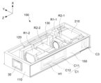
도 1은 본 발명의 바람직한 일 실시예에 의한 줌 구동용 액추에이터(이하 '액추에이터'라 지칭한다)(100) 및 카메라 모듈(1000)의 전체적인 구성을 도시한 도면이다.Figure 1 is a diagram showing the overall configuration of a zoom driving actuator (hereinafter referred to as 'actuator') 100 and a
본 발명의 액추에이터(100)는 자체로서 단일의 장치로 구현될 수 있음은 물론이며, 도 1에 도시된 바와 같이 반사계 모듈(200) 등이 포함되는 카메라 모듈(1000)로도 구현될 수 있다.Of course, the
본 발명의 액추에이터(100)는 후술되는 바와 같이 렌즈(렌즈조립체)가 탑재된 하나 이상의 캐리어를 광축 방향으로 선형 이동시켜 자동초점(AF, Auto Focus) 또는 줌(Zoom, continuous Zoom) 등의 기능을 구현하는 액추에이터에 해당한다.As will be described later, the
액추에이터(100)의 전방 내지 상부(광축 방향, 도면 기준 Z축 방향 기준)에 구비될 수 있는 반사계 모듈(200)은 피사체의 빛(light) 경로(Z1)를 렌즈 방향의 경로(Z)로 반사 내지 굴절시키는 기능을 수행한다. 이와 같이 광축 방향으로 반사 내지 굴절된 빛은 캐리어(120, 130)에 구비되는 렌즈(렌즈조립체)를 거쳐 CMOS, CCD 등과 같은 이미지센서(30)로 유입된다.The
빛의 경로를 변경시키는 반사계 모듈(200)은 미러(mirror) 또는 프리즘(prism) 중 선택된 하나 또는 이들의 조합으로 이루어질 수 있는 반사계(210)를 포함할 수 있다. 이 반사계(210)는 외계에서 유입되는 빛을 광축 방향으로 변경시킬 수 있는 다양한 부재에 의하여 구현될 수 있으나, 광학적 성능을 향상시키기 위하여 유리(glass) 재질로 구현하는 것이 바람직하다.The
반사계 모듈(200) 등이 함께 포함되는 본 발명의 카메라 모듈(1000)은 빛의 경로를 굴절시켜 빛이 렌즈 방향으로 유입되도록 구성되므로 장치 자체를 휴대 단말(스마트폰 등)의 두께 방향으로 설치하지 않고 길이 방향으로 설치할 수 있어 휴대 단말의 두께를 증가시키지 않아 휴대 단말의 소형화 내지 슬림화 등에 최적화될 수 있다.The
실시형태에 따라서, 반사계(210)는 마그네트 및 코일(C3, 도 2 참조)과 같은 자기력을 발생시키는 구동수단 및 위치감지센서 등에 의하여 회전 이동되도록 구성될 수 있다. Depending on the embodiment, the
이와 같이 반사계(210)가 이동 또는 회전 이동하면, 반사계(210)를 통하여 반사(굴절)되는 피사체의 빛이 ±Y 방향 및/또는 ±X 방향으로 이동하게 되므로 손떨림 등에 의한 X축 및/또는 Y축 방향 보정이 구현될 수 있다.In this way, when the
반사계 모듈(200)을 통하여 반사된 피사체의 빛은 광축 방향(Z축)을 기준으로 선형 이동하는 하나 이상의 캐리어(120, 130)에 탑재되는 하나 이상 렌즈(R2-1, R1-1, R2-2, R1-2 등)로 입사되며, 본 발명의 액추에이터(100)에 의하여 하나 이상 렌즈의 위치(광축 방향 기준)가 조합적으로 조정됨으로써 줌 또는 AF 등의 기능이 구현된다.The light of the subject reflected through the
도면에는 하우징(110)을 상대적 고정체로 광축 방향으로 이동하는 두 개의 캐리어(120, 130)가 도시되어 있으나 이는 하나의 예시로서, 이와는 다른 개수의 캐리어가 구비될 수 있음은 물론이며, 광학적 스펙이나 성능 등에 따라서 고정식 렌즈가 하우징(110) 등에 구비될 수도 있다.In the drawing, two
이하 본 발명의 설명에 있어, 렌즈 등으로 빛이 유입되는 경로에 대응되는 방향축을 광축(Z축)으로 정의하며, 이 광축(Z축)과 수직한 두 축을 X축 및 Y축으로 정의한다.In the following description of the present invention, the direction axis corresponding to the path through which light flows into a lens, etc. is defined as the optical axis (Z-axis), and the two axes perpendicular to this optical axis (Z-axis) are defined as the X-axis and Y-axis.
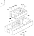
도 2는 본 발명의 바람직한 일 실시예에 의한 액추에이터(100)의 전체적인 구성을 도시한 도면이며, 도 3은 본 발명의 일 실시예에 의한 캐리어(120, 130) 및 이와 관련된 구성을 도시한 도면이다.FIG. 2 is a diagram showing the overall configuration of the
본 발명의 액추에이터(100)는 액추에이터(100)의 기본적인 프레임 구조에 해당하며 내부 구성을 수용하는 하우징(110), 제1캐리어(120) 및 제2캐리어(130) 등을 포함한다.The
제1캐리어(120) 또는/및 제2캐리어(130)는 광축 방향(Z축 방향)을 기준으로 선형 이동하는 이동체에 해당하며, 이에 상응하는 상대적 관점에서 하우징(110)은 고정체에 해당한다. 실시형태에 따라서 제1캐리어(120) 및 제2캐리어(130) 모두 광축 방향으로 독립된 방식에 의하여 이동할 수도 있으며 이 중 하나만 광축 방향으로 이동하도록 구성될 수 있다.The
후술되는 바와 같이 제1캐리어(120)에는 광축 방향 구동을 위한 제1마그네트(M1)가 탑재되며, 제1렌즈(R1-1, R1-2)가 장착되는 제1마운터(123, 124, 도 4 참조)가 형성될 수 있다. 하우징(110)에는 제1마그네트(M1)와 대면하여 제1마그네트(M1)에 구동력을 제공하는 제1코일(C1)이 배치된다. As will be described later, the
제1캐리어(120)의 확장된 가동영역/가동구간(스트로크, stroke)에 상응할 수 있도록 상기 제1코일(C1)은 도면에 예시된 바와 같이 광축 방향을 따라 상하로 배치되는 복수 개의 코일(C11, C12)로 구현되는 것이 바람직하다.To correspond to the expanded movable area/movement section (stroke) of the
구동드라이버(미도시)의 제어에 의하여 적절한 크기와 방향의 전원이 제1코일(C1)로 인가되면 제1코일(C1)과 제1마그네트(M1) 사이에 전자기력이 발생하고 이 발생된 전자기력에 의하여 제1캐리어(120)가 광축 방향으로 진퇴(forward and backward) 이동한다.When power of an appropriate size and direction is applied to the first coil (C1) under the control of a drive driver (not shown), electromagnetic force is generated between the first coil (C1) and the first magnet (M1), and this generated electromagnetic force As a result, the
이와 같이 제1캐리어(120)가 광축 방향으로 선형 이동하면, 제1캐리어에 탑재된 제1렌즈(R1-1, R1-2) 또한, 광축 방향으로 선형 이동하게 되므로 렌즈의 상대적인 위치 관계에 의하여 AF 또는 줌 기능 등이 구현된다. In this way, when the
제1코일(C1)에서 발생된 전자기력이 외부로 누설되는 것을 방지하고 제1마그네트(M1) 방향으로 더욱 집중되도록 제1마그네트(M1)와 대면하는 제1코일(C1)의 반대 반향에는 금속재질의 요크 플레이트가 구비될 수 있다.To prevent the electromagnetic force generated in the first coil (C1) from leaking to the outside and to be more concentrated in the direction of the first magnet (M1), a metal material is used in the opposite reflection of the first coil (C1) facing the first magnet (M1). A yoke plate may be provided.
제1홀센서(H1)는 홀효과(hall effect)를 이용하여 대향하는 방향의 제1마그네트(M1)에서 발생되는 자기장의 크기와 방향을 감지하고 이에 대응되는 신호를 구동드라이버로 출력한다.The first Hall sensor (H1) uses the Hall effect to detect the size and direction of the magnetic field generated from the first magnet (M1) in the opposite direction and outputs a corresponding signal to the driving driver.
구동드라이버는 제1홀센서(H1)로부터 입력된 신호를 연산 처리하고 그 결과에 대응하는 크기와 방향의 전원이 제1코일(C1)로 인가되도록 제어한다.The driving driver calculates and processes the signal input from the first Hall sensor (H1) and controls the result so that power of a magnitude and direction corresponding to the result is applied to the first coil (C1).
제1홀센서(H1)의 감지 및 구동드라이버의 제어 프로세싱은, 시계열적이며 연속적인 제어를 통하여 구동 정밀성이 더욱 향상될 수 있도록 피드백 제어를 통하여 순환적으로 적용되도록 구성되는 것이 바람직하다.The detection of the first Hall sensor H1 and the control processing of the driving driver are preferably configured to be applied cyclically through feedback control so that driving precision can be further improved through time-series and continuous control.
구동드라이버는 독립된 전자 부품, 소자 등으로 구현될 수도 있음은 물론이나 SOC(System On Chip) 등을 통하여 제1홀센서(H1) 등과 통합된 단일 전자부품(chip)의 형태로 구현될 수 있음은 물론이다.The driving driver may be implemented as an independent electronic component or device, but may also be implemented as a single electronic component (chip) integrated with the first Hall sensor (H1) through SOC (System On Chip). Of course.
또한, 제1코일(C1), 제1홀센서(H1) 등은 외부 모듈, 전원부, 외부 장치 등과 전기적/신호적으로 인터페이싱(interfacing)되는 회로기판(150)(FPCB) 상에 실장될 수 있음은 물론이다.In addition, the first coil (C1), the first Hall sensor (H1), etc. may be mounted on the circuit board (FPCB) 150 (FPCB) that is electrically/signally interfaced with external modules, power supplies, external devices, etc. Of course.
실시형태에 따라서 도면에 예시된 바와 같이 광축으로 선형 이동하는 캐리어(120, 130)는 복수 개가 구비될 수 있다. 제1캐리어(120)의 선형 이동 등과 관련하여 앞서 설명된 구성들은 다른 캐리어인 제2캐리어(130)의 선형 이동에 관련된 구성들(제2코일(C2), 제2홀센서(H2), 제2마그네트(M2) 등)에도 적용될 수 있으므로 이들에 대한 상세한 설명은 생략한다.Depending on the embodiment, as illustrated in the drawing, a plurality of
제1캐리어(120)가 최소화된 마찰력으로 더욱 유연하게 선형 이동할 수 있도록 제1캐리어(120)와 하우징(110) 사이에는 볼(B)이 배치되는 것이 바람직하다.It is preferable that a ball B is placed between the
제1캐리어(120)의 선형 이동이 효과적으로 유도되도록 제1캐리어(120)의 하부에 구비된 제1가이딩레일(126, 도 4 참조)과 하우징(110)의 바닥면에 구비된 홈부레일(111) 사이에 볼(B)이 배치되는 것이 바람직하다.A first guiding rail (126, see FIG. 4) provided on the lower part of the
이 경우, 선형적 이동에 대한 효과적인 가이딩이 구현되도록 볼(B)은 홈부레일(111) 또는/및 제1가이딩레일(126) 중 하나 이상에 그 일부가 수용되는 형태가 되도록 구성되는 것이 바람직하다.In this case, the ball B is configured so that a portion of it is accommodated in one or more of the
이와 같이 볼(B)이 개재되는 경우, 볼의 구름(rolling), 이동(moving), 회전(rotation), 대면 객체와의 점접촉(point-contact) 등에 의한 최소화된 마찰력으로 제1캐리어(120)가 더욱 유연하게 선형 이동할 수 있고 소음 감소 및 구동력 최소화는 물론, 구동 정밀성 등이 향상되는 장점을 가질 수 있다.In this way, when the ball B is interposed, the first carrier 120 ) can move linearly more flexibly and have the advantage of reducing noise and minimizing driving force, as well as improving driving precision.
이와 상응하는 관점에서 제2캐리어(130)의 하부에 구비된 제2가이딩레일(136, 도 4 참조)과 하우징(110)의 홈부레일(111) 사이에도 볼(B)이 배치될 수 있음은 물론이다.From a corresponding viewpoint, the ball B can also be placed between the second guiding rail 136 (see FIG. 4) provided at the lower part of the
제1캐리어(120) 및 제2캐리어(130) 모두 독립된 구동이 이루어지는 경우 도 3에 도시된 실시예를 기준으로 할 때, 제1캐리어(120)가 광축 방향으로 선형 이동하면 제1캐리어(120)에 탑재된 제1렌즈(R1-1, R1-2)가 광축 방향으로 이동하며, 제2캐리어(130)가 이동하면 그에 따라 제2캐리어(130)에 탑재된 제2렌즈(R2-1, R2-2)가 광축 방향으로 이동한다.When both the
제1캐리어(120)에 탑재되는 제1렌즈(R1-1, R1-2) 사이(광축 방향 기준)에 위치하는 제2렌즈(R2-2)만 제2캐리어(130)에 구비되는 형태를 비롯하여, 실시형태에 따라서 제1캐리어(120) 또는 제2캐리어(130)에 탑재되는 렌즈의 개수는 도면에 예시된 개수와 다르게 구비될 수 있음은 물론이다.Only the second lens (R2-2) located between the first lenses (R1-1, R1-2) mounted on the first carrier 120 (based on the optical axis direction) is provided on the
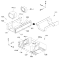
도 4는 본 발명의 일 실시예에 의한 제1캐리어(120) 등의 상세 구성을 도시한 도면이다.Figure 4 is a diagram showing the detailed configuration of the
도 4에 예시된 바와 같이 본 발명의 제1캐리어(120)는 제1캐리어(120)의 내구성 등의 증강을 위하여 금속 등과 같이 고강도 재질로 이루어지는 제1지지부재(121) 및 이 제1지지부재(121)가 인서트되어 성형(사출 성형 등)되는 제1몸체부(122)를 포함하여 구성될 수 있다.As illustrated in FIG. 4, the
제1지지부재(121)는 실시형태에 따라서 복수 개 유닛을 포함하는 형태로 이루어질 수도 있으나, 내구성 증강, 조립 성형의 효율성 등을 높이기 위하여 도면에 도시된 바와 같이 일체형으로 이루어지는 것이 바람직하다.The
제1캐리어(120), 구체적으로 제1캐리어(120)의 전체적인 형상이나 구조 등을 형성하는 제1몸체부(122)는 상기 제1지지부재(121)가 인서트되는 사출 성형 등의 방식으로 구현될 수 있으며, 도면에 도시된 바와 같이 제1지지부재(121)의 일부분인 제1파트(121a)가 노출되도록 구성된다. 실시형태에 따라서 제1캐리어(120)는 제1파트(121a)가 노출되는 제1공간(125)을 가질 수 있다.The
제1파트(121a)는 제2캐리어(130)와 대면하는 부분으로서, 제1지지부재(121) 중 외부로 노출되는 부분이므로 제2캐리어(130)와 대면하는 부분의 두께 내지 부피를 감소시킬 수 있다.The
또한, 제1캐리어(120)는 광축을 기준으로 제1파트(121a) 또는 제1공간(125)의 반대편에 형성되는 제1가이딩공간(120A)을 포함한다. 이 제1가이딩공간(120A)은 후술되는 바와 같이 제2캐리어(130)에 속한 제2지지부재(131)의 제2파트(131a)에 상응하는 공간으로서 제2파트(131a)를 가이딩한다.Additionally, the
제1캐리어(120)는 단일 개수 또는 북수 개의 제1렌즈(R1-1, R1-2)가 서로 이격되어 설치되도록 제1렌즈(R1-1, R1-2)가 탑재되며 광축 방향을 기준으로 상호 이격되는 하나 이상의 제1마운터(123, 124)를 포함한다.The
제1마운터(123, 124)는 제1몸체부(122)에 의하여 형성되는 공간으로 구성될 수 있으며, 실시형태에 따라서 제1몸체부(122)에 의한 파트와 함께 제1지지부재(121)가 노출되는 파트에 의하여 형성되는 공간으로 구성될 수도 있다.The
도면에 도시된 바와 같이 제1마운터(123, 124)의 바닥면(X축 기준)이 제1지지부재(121)가 노출되는 파트로 구성되는 경우, 높이(X축 기준)를 낮출 수 있으므로 액추에이터(100) 자체의 두께 방향 크기(휴대 단말의 두께)를 감소시킬 수 있다.As shown in the drawing, when the bottom surface (based on the (100) It is possible to reduce its size in the thickness direction (thickness of the mobile terminal).
앞서 기술된 바와 같이 제1캐리어(120)의 하부(X축 기준)에는 볼(B)이 배치되는 제1가이딩레일(126)이 형성되며, 실시형태에 따라서 하우징(110)에 구비되는 금속재질의 요크 플레이트(미도시)와 인력을 발생시키는 흡입마그네트(Ma)가 구비될 수 있다.As previously described, a
제1캐리어(120)는 광축을 기준으로 제1파트(121a)의 반대 방향 측면에 형성되며, 하우징(110)에 구비된 제1코일(C1)과 대면하는 제1마그네트(M1)가 탑재되는 제1탑재부(127)를 포함할 수 있다. The
이 경우, 도 4의 아래 도면에 도시된 바와 같이 제1가이딩공간(120A)은 제1탑재부(127)와 제1마운터(123) 사이에 형성되는 것이 바람직하다. In this case, as shown in the drawing below in FIG. 4, the
이와 같이 구성되는 경우, 제1캐리어(120)와 제2캐리어(130)는 각각 독립적으로 이동할 수 있음은 물론, 가이딩을 위한 추가적인 물리적 구조를 적용하지 않고도 각각의 일부 구성이 상호 교차 내지 중첩/적층되는 형태의 물리적 구조로 구현될 수 있어 공간 활용성을 더욱 높일 수 있다.When configured in this way, not only can the
도 5는 본 발명의 일 실시예에 의한 제2캐리어(130) 등의 상세 구성을 도시한 도면이다.Figure 5 is a diagram showing the detailed configuration of the
제2캐리어(130)는 전체적으로 상술된 제1캐리어(120)와 상응하는 구조를 가지되, 제1캐리어(120)와 전체적으로 대칭되는 구조 내지 형상을 가지도록 구성된다.The
구체적으로 제2캐리어(130)는 제2지지부재(131) 및 상기 제2지지부재(131)의 일부분인 제2파트(131a)가 노출되도록 상기 제2지지부재(131)가 인서트되어 성형되는 제2몸체부(132)를 포함한다.Specifically, the
제2공간(135) 등을 통하여 노출되는 제2지지부재(131)의 제2파트(131a)는 전술된 제1캐리어(120)와 대면하는 부분으로서 제2지지부재(131)가 그대로 외부로 노출되도록 구성되므로 제1캐리어(120)와 대면하는 부분의 두께 내지 부피를 감소시킬 수 있다.The
또한, 제2캐리어(130)는 제2파트(131a)의 반대 방향(Y축 기준)에 형성되며 제1캐리어(120)의 제1파트(121a)를 가이딩하는 제2가이딩공간(130A)을 포함한다.In addition, the
상기 제2캐리어(130)의 제2파트(131a)와 제2가이딩공간(130A)은 앞서 기술된 제1캐리어(120)의 제1파트(121a)와 제1가이딩공간(120A) 각각과 반대방향에 위치한다.The second part (131a) and the second guiding space (130A) of the
예시적으로, 제1캐리어(120)의 제1파트(121a)가 제1캐리어(120)의 좌측(Y축 방향 기준) 방향에 위치하는 경우, 제1공간(125) 등을 통하여 노출되는 제1파트(121a)를 가이딩하는 제2캐리어(130)의 제2가이딩공간(130A) 또한, 좌측 방향에 위치한다.For example, when the
아울러 이 경우, 제1캐리어(120)의 제1가이딩공간(120A) 즉, 제2캐리어(130)에 속한 구성으로서 제2공간(135) 등을 통하여 노출되는 제2지지부재(131)의 제2파트(131a)를 가이딩하는 제1가이딩공간(120A)은 제1캐리어(120)의 우측(Y축 방향 기준) 방향에 위치한다.In addition, in this case, the
상기 제2캐리어(130)는 렌즈가 탑재되는 m개(m은 1이상의 자연수) 제2마운터(133, 134)를 포함하되, 상기 제2마운터(133, 134) 중 하나 이상은 상기 복수 개 제1마운터(123, 124) 사이(광축 방향(Z축) 기준)에 위치하도록 구성된다.The
이와 같이 구성되는 경우, 동일한 간격을 유지한 상태로 함께 이동하는 복수 개 제1렌즈(예를 들어, R1-1, R1-2) 사이에 제2렌즈(R2-1, R2-2) 중 하나 이상이 위치하므로 복수 개 렌즈들의 이동에 따른 다양한 조합적 적용이 가능하게 된다.In the case of this configuration, one of the second lenses (R2-1, R2-2) is provided between the plurality of first lenses (e.g., R1-1, R1-2) that move together while maintaining the same spacing. Since the above is located, various combinatorial applications are possible according to the movement of a plurality of lenses.
제2마운터(133, 134)는 제2몸체부(132)에 의하여 형성되는 공간으로 구성될 수 있으며, 실시형태에 따라서 제2몸체부(132)에 의한 파트와 함께 제2지지부재(131)가 노출되는 파트에 의하여 형성되는 공간으로 구성될 수도 있다.The
도면에 도시된 바와 같이 제2마운터(133, 134)의 바닥면(X축 기준)이 제2지지부재(131)가 노출되는 파트로 구성되는 경우, 높이(X축 기준)를 낮출 수 있으므로 액추에이터(100) 자체의 두께 방향 크기(휴대 단말의 두께)를 감소시킬 수 있다.As shown in the drawing, when the bottom surface (based on the (100) It is possible to reduce its size in the thickness direction (thickness of the mobile terminal).
제2캐리어(120)의 하부(X축 기준)에는 볼(B)이 배치되는 제2가이딩레일(136)이 형성되며, 실시형태에 따라서 하우징(110)에 구비되는 금속재질의 요크 플레이트(미도시)와 인력을 발생시키는 흡입마그네트(Ma)가 구비될 수 있다.A
제2캐리어(130)는, 제2파트(131a)의 반대 방향(Y축 기준) 측면에 형성되며 하우징(110)에 구비된 제2코일(C2)과 대면하는 제2마그네트(M2)가 탑재되는 제2탑재부(137)를 포함할 수 있다. 이 경우, 도 5에 도시된 바와 같이 제2가이딩공간(130A)은 제2탑재부(137)와 제2마운터(134) 사이에 형성되는 것이 바람직하다. The
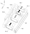
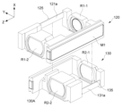
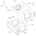
도 6은 제1 및 제2캐리어(120, 130)가 결합된 모습을 도시한 도면이며, 도 7 및 도 8은 제1캐리어(120)와 제2캐리어(130)가 결합되는 관계를 도시한 도면이다.Figure 6 is a diagram showing the first and
도 6에는 제1캐리어(120) 및 제2캐리어(130) 모두 독립적으로 광축 방향으로 이동하며 각 캐리어(120, 130)에는 복수 개의 렌즈가 설치된 액추에이터(100)의 실시예가 도시되어 있다.Figure 6 shows an embodiment of the
도 6에 도시된 바와 같이 제1캐리어(120)가 광축 방향으로 이동하는 경우 설계된 거리만큼 물리적으로 이격된 복수 개 제1렌즈(R1-1, R1-2)가 이격된 거리를 유지하면서 광축 방향으로 이동한다.As shown in FIG. 6, when the
이와 독립적으로 제2캐리어(130)가 광축 방향으로 진퇴 이동하면, 적절한 거리만큼 이격된 복수 개 제2렌즈(R2-1, R2-2)가 광축 방향으로 이동한다. 이러한 각 캐리어의 독립된 이동에 따라 제1렌즈(R1-1, R1-2) 및 제2렌즈(R2-1, R2-2)의 상대적 거리에 따른 다양한 조합이 적용되며 이를 통하여 연속적으로 변화되는 배율의 줌 기능이 구현된다.Independently of this, when the
제1캐리어(120)와 제2캐리어(130)는 독립된 자신만의 개별 공간을 차지하는 것이 아니라, 앞서 상술된 본 발명만의 구조적 적용을 통하여 상당 부분의 공간이 상호 중첩 내지 교차되도록 구성된다.The
즉, 제1캐리어(120)와 제2캐리어(130)는 상기 제1파트(121a)와 상기 제2가이딩공간(130A) 사이 그리고 상기 제2파트(131a)와 상기 제1가이딩공간(120A) 사이의 상호 가이딩을 통하여 이동 구간 중 일부가 중첩되도록 구성된다.That is, the
또한, 제1캐리어(120)와 제2캐리어(130)는 제1파트(121a) 및 제2파트(131a)와 같이 사출 구조물에 비하여 상대적으로 크게 얇은 객체와 이에 상응하는 구성이 서로 대면하는 구조를 가지므로 공간 효율성을 더욱 높일 수 있다.In addition, the
도 7 및 도 8에 예시된 도시된 바와 같이, 제1캐리어(120)에 속한 제1지지부재(121)의 제1파트(121a)는 제2캐리어(130)의 제2가이딩공간(130A)에 안착되며, 이 과정에서 제2캐리어(130)에 속한 제2지지부재(131)의 제2파트(131a)는 제1캐리어(120)의 제1가이딩공간(120A)으로 유입될 수 있다.As illustrated in FIGS. 7 and 8, the
이와 같이 상호 대응하는 구조를 더욱 효과적으로 구현하기 위하여 제1가이딩공간(120A) 또는 제2가이딩공간(130A) 중 하나는 상부(X축 기준)가 차단되고 하부가 개방되는 형상을 가지며, 다른 하나는 이와 반대로 상부가 개방되고 하부가 차단되는 형상을 가지도록 구성될 수 있다.In order to more effectively implement such mutually corresponding structures, one of the first guiding space (120A) or the second guiding space (130A) has a shape in which the upper part (based on the On the contrary, one may be configured to have a shape in which the upper part is open and the lower part is blocked.
도면에는 이에 대한 일 예로, 제1캐리어(120)가 제2캐리어(130)의 상부에 위치하는 실시예가 도시되어 있다. 이 경우 제1캐리어(120)의 제1파트(121a)는 제2캐리어(130)의 제2가이딩공간(130A)에, 제1캐리어(120)의 제1가이딩공간(120A)은 제2캐리어(130)의 제2파트(131a)에 위치하도록 하고 제1캐리어(120)를 제2캐리어(130) 방향으로 결합시키는 간단한 방법으로 양 캐리어를 조립할 수 있어 조립 공정의 효율성 또한, 높일 수 있다.As an example of this, the drawing shows an embodiment in which the
이와 같이 조립되는 경우, 인서트되는 구조체의 일부분으로서 사출물보다 상당히 얇은 제1파트(121a)와 제2파트(131a)가 서로 다른 캐리어의 상응하는 제2가이딩공간(130A) 및 제1가이딩공간(120A)을 통하여 서로 대면하게 되므로 폭 방향(Y축 방향)의 길이 또한, 감소시킬 수 있어 공간 적응성을 더욱 높일 수 있다.When assembled in this way, the first part (121a) and the second part (131a), which are parts of the inserted structure and are considerably thinner than the injection molded product, are connected to the corresponding second guiding space (130A) and first guiding space of different carriers. Since they face each other through (120A), the length in the width direction (Y-axis direction) can also be reduced, further improving spatial adaptability.
아울러, 제1캐리어(120) 또는/및 제2캐리어(130)가 금속 재질과 같은 높은 강성을 가지며 인서트되는 지지부재에 의하여 물리적으로 지지되므로 캐리어 자체의 강성 증가는 물론, 각 캐리어의 물리적인 변형이나 광축 상에서의 틸팅(tilting) 등이 더욱 효과적으로 억제될 수 있다.In addition, since the
이상에서 본 발명은 비록 한정된 실시예와 도면에 의해 설명되었으나, 본 발명은 이것에 의해 한정되지 않으며 본 발명이 속하는 기술 분야에서 통상의 지식을 가진 자에 의해 본 발명의 기술사상과 아래에 기재될 특허청구범위의 균등범위 내에서 다양한 수정 및 변형이 가능함은 물론이다.Although the present invention has been described above with limited examples and drawings, the present invention is not limited thereto, and the technical idea of the present invention and the description below will be understood by those skilled in the art to which the present invention pertains. Of course, various modifications and variations are possible within the scope of equivalence of the patent claims.
상술된 본 발명의 설명에 있어 제1 및 제2 등과 같은 수식어는 상호 간의 구성요소를 상대적으로 구분하기 위하여 사용되는 도구적 개념의 용어일 뿐이므로, 특정의 순서, 우선순위 등을 나타내기 위하여 사용되는 용어가 아니라고 해석되어야 한다.In the description of the present invention described above, modifiers such as first and second are merely instrumental terms used to relatively distinguish components from each other, and are therefore used to indicate a specific order, priority, etc. It should be interpreted that it is not a valid term.
본 발명의 설명과 그에 대한 실시예의 도시를 위하여 첨부된 도면 등은 본 발명에 의한 기술 내용을 강조 내지 부각하기 위하여 다소 과장된 형태로 도시될 수 있으나, 앞서 기술된 내용과 도면에 도시된 사항 등을 고려하여 본 기술분야의 통상의 기술자 수준에서 다양한 형태의 변형 적용 예가 가능할 수 있음은 자명하다고 해석되어야 한다.The drawings attached to explain the present invention and illustrate its embodiments may be shown in a somewhat exaggerated form in order to emphasize or highlight the technical content of the present invention, but the contents described above and the matters shown in the drawings, etc. Considering this, it should be interpreted as obvious that various types of modifications and application examples may be possible at the level of a person skilled in the art.
1000 : 카메라 모듈
30 : 이미지센서
200 : 반사계 모듈
210 : 반사계
100 : 액추에이터
110 : 하우징
111 : 홈부레일
120 : 제1캐리어
120A : 제1가이딩공간
121 : 제1지지부재
121a : 제1파트
122 : 제1몸체부
123, 124 : 제1마운터
125 : 제1공간
126 : 제1가이딩레일
127 : 제1탑재부
130 : 제1캐리어
130A : 제2가이딩공간
131 : 제2지지부재
131a : 제2파트
132 : 제2몸체부
133, 134 : 제2마운터
135 : 제2공간
136 : 제2가이딩레일
137 : 제2탑재부
150 : 회로기판
B : 볼
M1 : 제1마그네트
M2 : 제2마그네트
C1 : 제1코일
C2 : 제2코일
H1 : 제1홀센서
H2 : 제2홀센서
R1-1, R1-2 : 제1렌즈
R2-1, R2-2 : 제2렌즈1000: Camera module 30: Image sensor
200: Reflectometer module 210: Reflectometer
100: Actuator 110: Housing
111: Home rail
120: first carrier
120A: first guiding space 121: first support member
121a: first part 122: first body part
123, 124: 1st mounter 125: 1st space
126: first guiding rail 127: first mounting unit
130: first carrier
130A: Second guiding space 131: Second support member
131a: second part 132: second body part
133, 134: 2nd mounter 135: 2nd space
136: 2nd guiding rail 137: 2nd mounting unit
150: Circuit board B: Ball
M1: 1st magnet M2: 2nd magnet
C1: 1st coil C2: 2nd coil
H1: 1st Hall sensor H2: 2nd Hall sensor
R1-1, R1-2: 1st lens R2-1, R2-2: 2nd lens
Claims (7)
제2지지부재, 상기 제2지지부재의 일부분인 제2파트가 노출되도록 상기 제2지지부재가 인서트되어 성형되는 제2몸체부와, 광축을 기준으로 상기 제2파트의 반대편에 형성되는 제2가이딩공간을 포함하는 제2캐리어를 포함하고,
상기 제1파트는 상기 제2가이딩공간에 의하여 가이딩되고, 상기 제2파트는 상기 제1가이딩공간에 의하여 가이딩되는 것을 특징으로 하는 줌 구동용 액추에이터.A first support member, a first body portion formed by inserting the first support member so that the first part, which is a part of the first support member, is exposed, and a first body portion formed on the opposite side of the first part with respect to the optical axis. A first carrier that includes a guiding space and moves in the direction of the optical axis with respect to the housing; and
A second support member, a second body portion formed by inserting the second support member so that the second part, which is a part of the second support member, is exposed, and a second body formed on the opposite side of the second part based on the optical axis. It includes a second carrier including a guiding space,
The first part is guided by the second guiding space, and the second part is guided by the first guiding space.
복수 개 렌즈가 각각 탑재되며 광축 방향을 기준으로 상호 이격되는 복수 개 제1마운터를 포함하고,
상기 제2캐리어는 렌즈가 탑재되는 m개(m은 1이상의 자연수) 제2마운터를 포함하되, 상기 제2마운터 중 하나 이상은 상기 복수 개 제1마운터 사이에 위치하는 것을 특징으로 하는 줌 구동용 액추에이터.The method of claim 1, wherein the first carrier is:
It includes a plurality of first mounters on which a plurality of lenses are each mounted and are spaced apart from each other based on the optical axis direction,
The second carrier includes m second mounters on which lenses are mounted (m is a natural number of 1 or more), and at least one of the second mounters is located between the plurality of first mounters. Actuator.
광축을 기준으로 상기 제1파트의 반대편 측면에 형성되며, 상기 하우징에 구비된 제1코일과 대면하는 제1마그네트가 탑재되는 제1탑재부를 포함하고,
상기 제1가이딩공간은 상기 제1마운터와 상기 제1탑재부 사이에 형성되는 것을 특징으로 하는 줌 구동용 액추에이터.The method of claim 2, wherein the first carrier is:
It is formed on a side opposite to the first part with respect to the optical axis and includes a first mounting part on which a first magnet facing the first coil provided in the housing is mounted,
An actuator for zoom driving, wherein the first guiding space is formed between the first mounter and the first mounting part.
광축을 기준으로 상기 제2파트의 반대편 측면에 형성되며, 상기 하우징에 구비된 제2코일과 대면하는 제2마그네트가 탑재되는 제2탑재부를 포함하고,
상기 제2가이딩공간은 상기 제2마운터와 상기 제2탑재부 사이에 형성되는 것을 특징으로 하는 줌 구동용 액추에이터.The method of claim 2, wherein the second carrier is:
It is formed on a side opposite to the second part with respect to the optical axis and includes a second mounting part on which a second magnet facing the second coil provided in the housing is mounted,
An actuator for zoom driving, wherein the second guiding space is formed between the second mounter and the second mounting part.
상하부를 기준으로 개방 부위의 방향성이 서로 반대인 것을 특징으로 하는 줌 구동용 액추에이터.The method of claim 1, wherein the first and second guiding spaces are,
An actuator for zoom driving, characterized in that the directions of the opening areas are opposite to each other based on the upper and lower parts.
상기 제1캐리어와 상기 하우징 사이 또는 상기 제2캐리어와 상기 하우징 사이 중 하나 이상에 배치되는 볼을 더 포함하는 것을 특징으로 하는 줌 구동용 액추에이터.According to paragraph 1,
An actuator for zoom driving, further comprising a ball disposed between the first carrier and the housing or between the second carrier and the housing.
상기 제1파트와 상기 제2가이딩공간 사이 및 상기 제2파트와 상기 제1가이딩공간 사이의 상호 가이딩을 통하여 이동 구간 중 일부가 중첩되는 것을 특징으로 하는 줌 구동용 액추에이터.The method of claim 1, wherein the first and second carriers are:
An actuator for zoom driving, wherein a portion of the movement section overlaps through mutual guiding between the first part and the second guiding space and between the second part and the first guiding space.
Priority Applications (2)
| Application Number | Priority Date | Filing Date | Title |
|---|---|---|---|
| KR1020220047917A KR20230148928A (en) | 2022-04-19 | 2022-04-19 | Actuator for driving zoom |
| PCT/KR2023/002741 WO2023204428A1 (en) | 2022-04-19 | 2023-02-27 | Zoom-driving actuator |
Applications Claiming Priority (1)
| Application Number | Priority Date | Filing Date | Title |
|---|---|---|---|
| KR1020220047917A KR20230148928A (en) | 2022-04-19 | 2022-04-19 | Actuator for driving zoom |
Publications (1)
| Publication Number | Publication Date |
|---|---|
| KR20230148928A true KR20230148928A (en) | 2023-10-26 |
Family
ID=88420208
Family Applications (1)
| Application Number | Title | Priority Date | Filing Date |
|---|---|---|---|
| KR1020220047917A KR20230148928A (en) | 2022-04-19 | 2022-04-19 | Actuator for driving zoom |
Country Status (2)
| Country | Link |
|---|---|
| KR (1) | KR20230148928A (en) |
| WO (1) | WO2023204428A1 (en) |
Family Cites Families (5)
| Publication number | Priority date | Publication date | Assignee | Title |
|---|---|---|---|---|
| KR20080075641A (en) * | 2007-02-13 | 2008-08-19 | 파워옵틱스 주식회사 | Zoom lens barrel and digital photographing device comprising the same |
| KR102443783B1 (en) * | 2018-03-08 | 2022-09-16 | 자화전자(주) | Actuator for camera |
| US11336830B2 (en) * | 2019-01-03 | 2022-05-17 | Corephotonics Ltd. | Multi-aperture cameras with at least one two state zoom camera |
| KR20200125221A (en) * | 2019-04-26 | 2020-11-04 | 엘지이노텍 주식회사 | Camera module and Camera Apparatus including the same |
| KR102400385B1 (en) * | 2020-11-12 | 2022-05-20 | 자화전자(주) | Actuator for driving zoom |
-
2022
- 2022-04-19 KR KR1020220047917A patent/KR20230148928A/en unknown
-
2023
- 2023-02-27 WO PCT/KR2023/002741 patent/WO2023204428A1/en unknown
Also Published As
| Publication number | Publication date |
|---|---|
| WO2023204428A1 (en) | 2023-10-26 |
Similar Documents
| Publication | Publication Date | Title |
|---|---|---|
| US10564442B2 (en) | Apparatus for driving optical-reflector for OIS with multi-axial structure | |
| US10921552B1 (en) | Autofocus apparatus and camera module including the same | |
| KR102423363B1 (en) | Actuator for zoom camera | |
| KR20180012150A (en) | Auto focussing apparatus for zoom lens | |
| US11333951B2 (en) | Actuator for camera | |
| KR102146385B1 (en) | Image sensor actuator for ois and camera module including it | |
| KR20200012421A (en) | Actuator for camera with module combination | |
| KR101729543B1 (en) | Single actuator for dual lens and camera module including the same | |
| KR20180076165A (en) | Camera module | |
| KR20180015966A (en) | Actuator for zoom lens | |
| KR102423685B1 (en) | Apparatus for operating lens | |
| KR20230148928A (en) | Actuator for driving zoom | |
| KR102400385B1 (en) | Actuator for driving zoom | |
| US20220155553A1 (en) | Imaging device and electronic device | |
| KR102533577B1 (en) | Actuator for reflector | |
| CN117616764A (en) | Rotating mechanism, camera module thereof, driving device and electronic equipment | |
| KR102351233B1 (en) | Actuator for auto focus and driving driver controlling it | |
| KR102467587B1 (en) | Actuator for driving zoom | |
| KR102565566B1 (en) | Actuator for driving zoom with differential structure | |
| KR20230157042A (en) | Actuator for camera | |
| KR20200144349A (en) | Camera actuator | |
| KR20100071565A (en) | Camera module | |
| KR102467588B1 (en) | Actuator for driving zoom | |
| US20220317412A1 (en) | Actuator for driving zoom | |
| KR20230140031A (en) | Actuator for camera |