KR20230145211A - Method and apparatus for forming advanced polishing pads using an additive manufacturing process - Google Patents
Method and apparatus for forming advanced polishing pads using an additive manufacturing process Download PDFInfo
- Publication number
- KR20230145211A KR20230145211A KR1020237033070A KR20237033070A KR20230145211A KR 20230145211 A KR20230145211 A KR 20230145211A KR 1020237033070 A KR1020237033070 A KR 1020237033070A KR 20237033070 A KR20237033070 A KR 20237033070A KR 20230145211 A KR20230145211 A KR 20230145211A
- Authority
- KR
- South Korea
- Prior art keywords
- polishing
- polishing pad
- pad
- layer
- polymer
- Prior art date
Links
- 238000005498 polishing Methods 0.000 title claims abstract description 1162
- 238000000034 method Methods 0.000 title claims abstract description 153
- 239000000654 additive Substances 0.000 title abstract description 86
- 238000004519 manufacturing process Methods 0.000 title abstract description 85
- 230000000996 additive effect Effects 0.000 title abstract description 79
- 239000000463 material Substances 0.000 claims abstract description 567
- 239000000203 mixture Substances 0.000 claims abstract description 409
- 229920000642 polymer Polymers 0.000 claims abstract description 249
- 239000002243 precursor Substances 0.000 claims abstract description 192
- 239000003795 chemical substances by application Substances 0.000 claims abstract description 70
- 238000009472 formulation Methods 0.000 claims description 111
- 229920005989 resin Polymers 0.000 claims description 101
- 239000011347 resin Substances 0.000 claims description 101
- 239000000178 monomer Substances 0.000 claims description 60
- NIXOWILDQLNWCW-UHFFFAOYSA-M Acrylate Chemical compound [O-]C(=O)C=C NIXOWILDQLNWCW-UHFFFAOYSA-M 0.000 claims description 35
- 239000003361 porogen Substances 0.000 claims description 20
- 125000001931 aliphatic group Chemical group 0.000 claims description 17
- 230000005670 electromagnetic radiation Effects 0.000 claims description 17
- UHESRSKEBRADOO-UHFFFAOYSA-N ethyl carbamate;prop-2-enoic acid Chemical compound OC(=O)C=C.CCOC(N)=O UHESRSKEBRADOO-UHFFFAOYSA-N 0.000 claims description 16
- 238000009826 distribution Methods 0.000 claims description 14
- LYCAIKOWRPUZTN-UHFFFAOYSA-N Ethylene glycol Chemical compound OCCO LYCAIKOWRPUZTN-UHFFFAOYSA-N 0.000 claims description 9
- 239000007864 aqueous solution Substances 0.000 claims description 5
- 238000002360 preparation method Methods 0.000 claims description 4
- 239000012704 polymeric precursor Substances 0.000 claims 4
- 230000000379 polymerizing effect Effects 0.000 claims 4
- WGCNASOHLSPBMP-UHFFFAOYSA-N hydroxyacetaldehyde Natural products OCC=O WGCNASOHLSPBMP-UHFFFAOYSA-N 0.000 claims 2
- 230000008569 process Effects 0.000 abstract description 103
- 239000000126 substance Substances 0.000 abstract description 62
- 150000001875 compounds Chemical class 0.000 abstract description 35
- 239000003085 diluting agent Substances 0.000 abstract description 33
- 230000008021 deposition Effects 0.000 abstract description 21
- 238000007639 printing Methods 0.000 abstract description 20
- 230000001976 improved effect Effects 0.000 abstract description 18
- 229920001002 functional polymer Polymers 0.000 abstract description 9
- 239000003054 catalyst Substances 0.000 abstract description 2
- 239000010410 layer Substances 0.000 description 336
- 238000003860 storage Methods 0.000 description 184
- 239000000758 substrate Substances 0.000 description 129
- 238000001723 curing Methods 0.000 description 95
- 238000007517 polishing process Methods 0.000 description 67
- -1 functional polymers Chemical class 0.000 description 56
- 238000006243 chemical reaction Methods 0.000 description 48
- 239000002002 slurry Substances 0.000 description 47
- 239000000047 product Substances 0.000 description 39
- 230000001965 increasing effect Effects 0.000 description 35
- 230000005855 radiation Effects 0.000 description 34
- 238000006116 polymerization reaction Methods 0.000 description 31
- 239000004593 Epoxy Substances 0.000 description 28
- 239000002585 base Substances 0.000 description 28
- 238000012545 processing Methods 0.000 description 28
- 239000002245 particle Substances 0.000 description 27
- 238000000151 deposition Methods 0.000 description 26
- 230000015572 biosynthetic process Effects 0.000 description 25
- 239000011800 void material Substances 0.000 description 25
- 238000007151 ring opening polymerisation reaction Methods 0.000 description 24
- 239000002609 medium Substances 0.000 description 23
- 239000002861 polymer material Substances 0.000 description 23
- 230000000694 effects Effects 0.000 description 22
- 238000002156 mixing Methods 0.000 description 21
- 150000001252 acrylic acid derivatives Chemical class 0.000 description 20
- 150000001412 amines Chemical class 0.000 description 20
- 238000013461 design Methods 0.000 description 20
- 230000009477 glass transition Effects 0.000 description 20
- 150000003254 radicals Chemical class 0.000 description 20
- 239000002131 composite material Substances 0.000 description 19
- 238000004132 cross linking Methods 0.000 description 18
- QVGXLLKOCUKJST-UHFFFAOYSA-N atomic oxygen Chemical compound [O] QVGXLLKOCUKJST-UHFFFAOYSA-N 0.000 description 17
- 239000001301 oxygen Substances 0.000 description 17
- 229910052760 oxygen Inorganic materials 0.000 description 17
- 238000012360 testing method Methods 0.000 description 17
- OXBLVCZKDOZZOJ-UHFFFAOYSA-N 2,3-Dihydrothiophene Chemical compound C1CC=CS1 OXBLVCZKDOZZOJ-UHFFFAOYSA-N 0.000 description 16
- 239000000976 ink Substances 0.000 description 16
- CERQOIWHTDAKMF-UHFFFAOYSA-M Methacrylate Chemical compound CC(=C)C([O-])=O CERQOIWHTDAKMF-UHFFFAOYSA-M 0.000 description 15
- 125000004122 cyclic group Chemical group 0.000 description 15
- 239000004814 polyurethane Substances 0.000 description 15
- 229920002635 polyurethane Polymers 0.000 description 15
- XLYOFNOQVPJJNP-UHFFFAOYSA-N water Substances O XLYOFNOQVPJJNP-UHFFFAOYSA-N 0.000 description 15
- 125000003118 aryl group Chemical group 0.000 description 14
- 238000011084 recovery Methods 0.000 description 14
- 239000004094 surface-active agent Substances 0.000 description 14
- IJGRMHOSHXDMSA-UHFFFAOYSA-N Atomic nitrogen Chemical compound N#N IJGRMHOSHXDMSA-UHFFFAOYSA-N 0.000 description 13
- 230000008901 benefit Effects 0.000 description 13
- 125000002091 cationic group Chemical group 0.000 description 13
- 230000002209 hydrophobic effect Effects 0.000 description 13
- 230000002829 reductive effect Effects 0.000 description 12
- 238000010146 3D printing Methods 0.000 description 11
- NIXOWILDQLNWCW-UHFFFAOYSA-N acrylic acid group Chemical group C(C=C)(=O)O NIXOWILDQLNWCW-UHFFFAOYSA-N 0.000 description 11
- 150000001993 dienes Chemical class 0.000 description 11
- 150000002118 epoxides Chemical group 0.000 description 11
- 230000006870 function Effects 0.000 description 11
- 238000005698 Diels-Alder reaction Methods 0.000 description 10
- 239000002202 Polyethylene glycol Substances 0.000 description 10
- 238000012644 addition polymerization Methods 0.000 description 10
- 230000008859 change Effects 0.000 description 10
- 238000010438 heat treatment Methods 0.000 description 10
- 229920000728 polyester Polymers 0.000 description 10
- 229920001223 polyethylene glycol Polymers 0.000 description 10
- 239000011148 porous material Substances 0.000 description 10
- 208000014117 bile duct papillary neoplasm Diseases 0.000 description 9
- 239000006227 byproduct Substances 0.000 description 9
- 125000004386 diacrylate group Chemical group 0.000 description 9
- 239000004615 ingredient Substances 0.000 description 9
- 239000007788 liquid Substances 0.000 description 9
- 230000000704 physical effect Effects 0.000 description 9
- UMIVXZPTRXBADB-UHFFFAOYSA-N benzocyclobutene Chemical compound C1=CC=C2CCC2=C1 UMIVXZPTRXBADB-UHFFFAOYSA-N 0.000 description 8
- 238000007906 compression Methods 0.000 description 8
- 230000006835 compression Effects 0.000 description 8
- 230000003750 conditioning effect Effects 0.000 description 8
- 125000003700 epoxy group Chemical group 0.000 description 8
- 239000000017 hydrogel Substances 0.000 description 8
- 239000003999 initiator Substances 0.000 description 8
- 238000011068 loading method Methods 0.000 description 8
- 230000007246 mechanism Effects 0.000 description 8
- 239000007787 solid Substances 0.000 description 8
- 229920001187 thermosetting polymer Polymers 0.000 description 8
- 238000007259 addition reaction Methods 0.000 description 7
- 229920001577 copolymer Polymers 0.000 description 7
- 229920000647 polyepoxide Polymers 0.000 description 7
- 229920001169 thermoplastic Polymers 0.000 description 7
- JOYRKODLDBILNP-UHFFFAOYSA-N Ethyl urethane Chemical compound CCOC(N)=O JOYRKODLDBILNP-UHFFFAOYSA-N 0.000 description 6
- 238000006845 Michael addition reaction Methods 0.000 description 6
- 229920001730 Moisture cure polyurethane Polymers 0.000 description 6
- VYPSYNLAJGMNEJ-UHFFFAOYSA-N Silicium dioxide Chemical compound O=[Si]=O VYPSYNLAJGMNEJ-UHFFFAOYSA-N 0.000 description 6
- 125000000217 alkyl group Chemical group 0.000 description 6
- 238000010586 diagram Methods 0.000 description 6
- 239000012530 fluid Substances 0.000 description 6
- RAXXELZNTBOGNW-UHFFFAOYSA-N imidazole Natural products C1=CNC=N1 RAXXELZNTBOGNW-UHFFFAOYSA-N 0.000 description 6
- 230000005764 inhibitory process Effects 0.000 description 6
- 230000003993 interaction Effects 0.000 description 6
- 239000012705 liquid precursor Substances 0.000 description 6
- 230000033001 locomotion Effects 0.000 description 6
- 229910052751 metal Inorganic materials 0.000 description 6
- 239000002184 metal Substances 0.000 description 6
- 229910052757 nitrogen Inorganic materials 0.000 description 6
- 230000036961 partial effect Effects 0.000 description 6
- 229920001296 polysiloxane Polymers 0.000 description 6
- 229910052724 xenon Inorganic materials 0.000 description 6
- FHNFHKCVQCLJFQ-UHFFFAOYSA-N xenon atom Chemical compound [Xe] FHNFHKCVQCLJFQ-UHFFFAOYSA-N 0.000 description 6
- 239000012958 Amine synergist Substances 0.000 description 5
- 238000012935 Averaging Methods 0.000 description 5
- ISWSIDIOOBJBQZ-UHFFFAOYSA-N Phenol Chemical compound OC1=CC=CC=C1 ISWSIDIOOBJBQZ-UHFFFAOYSA-N 0.000 description 5
- 238000005266 casting Methods 0.000 description 5
- 238000011960 computer-aided design Methods 0.000 description 5
- 230000007423 decrease Effects 0.000 description 5
- 230000007547 defect Effects 0.000 description 5
- 238000005137 deposition process Methods 0.000 description 5
- 239000006260 foam Substances 0.000 description 5
- 125000000524 functional group Chemical group 0.000 description 5
- 239000011261 inert gas Substances 0.000 description 5
- 239000010954 inorganic particle Substances 0.000 description 5
- 239000000543 intermediate Substances 0.000 description 5
- 239000011146 organic particle Substances 0.000 description 5
- 229920003229 poly(methyl methacrylate) Polymers 0.000 description 5
- 229920000058 polyacrylate Polymers 0.000 description 5
- 239000004926 polymethyl methacrylate Substances 0.000 description 5
- 239000002904 solvent Substances 0.000 description 5
- PZNSFCLAULLKQX-UHFFFAOYSA-N Boron nitride Chemical compound N#B PZNSFCLAULLKQX-UHFFFAOYSA-N 0.000 description 4
- KAKZBPTYRLMSJV-UHFFFAOYSA-N Butadiene Chemical compound C=CC=C KAKZBPTYRLMSJV-UHFFFAOYSA-N 0.000 description 4
- RTZKZFJDLAIYFH-UHFFFAOYSA-N Diethyl ether Chemical compound CCOCC RTZKZFJDLAIYFH-UHFFFAOYSA-N 0.000 description 4
- 238000005033 Fourier transform infrared spectroscopy Methods 0.000 description 4
- 239000005062 Polybutadiene Substances 0.000 description 4
- 239000004721 Polyphenylene oxide Substances 0.000 description 4
- DNIAPMSPPWPWGF-UHFFFAOYSA-N Propylene glycol Chemical compound CC(O)CO DNIAPMSPPWPWGF-UHFFFAOYSA-N 0.000 description 4
- 238000005299 abrasion Methods 0.000 description 4
- 239000000370 acceptor Substances 0.000 description 4
- 150000001336 alkenes Chemical class 0.000 description 4
- 238000004458 analytical method Methods 0.000 description 4
- 230000006399 behavior Effects 0.000 description 4
- 238000012656 cationic ring opening polymerization Methods 0.000 description 4
- 239000007822 coupling agent Substances 0.000 description 4
- 238000001514 detection method Methods 0.000 description 4
- 150000004985 diamines Chemical class 0.000 description 4
- 238000012672 diels-alder polymerization Methods 0.000 description 4
- 125000006575 electron-withdrawing group Chemical group 0.000 description 4
- 238000005516 engineering process Methods 0.000 description 4
- JBKVHLHDHHXQEQ-UHFFFAOYSA-N epsilon-caprolactam Chemical compound O=C1CCCCCN1 JBKVHLHDHHXQEQ-UHFFFAOYSA-N 0.000 description 4
- 125000005842 heteroatom Chemical group 0.000 description 4
- 239000008240 homogeneous mixture Substances 0.000 description 4
- 230000000670 limiting effect Effects 0.000 description 4
- 150000002739 metals Chemical class 0.000 description 4
- 238000000465 moulding Methods 0.000 description 4
- 150000004767 nitrides Chemical class 0.000 description 4
- 239000012038 nucleophile Substances 0.000 description 4
- 230000003287 optical effect Effects 0.000 description 4
- 229920003023 plastic Polymers 0.000 description 4
- 239000004033 plastic Substances 0.000 description 4
- 229920001606 poly(lactic acid-co-glycolic acid) Polymers 0.000 description 4
- 229920002857 polybutadiene Polymers 0.000 description 4
- 229920000515 polycarbonate Polymers 0.000 description 4
- 239000004417 polycarbonate Substances 0.000 description 4
- 229920000570 polyether Polymers 0.000 description 4
- 125000002924 primary amino group Chemical group [H]N([H])* 0.000 description 4
- 238000010526 radical polymerization reaction Methods 0.000 description 4
- 230000009467 reduction Effects 0.000 description 4
- 238000012546 transfer Methods 0.000 description 4
- 230000007704 transition Effects 0.000 description 4
- YHQGMYUVUMAZJR-UHFFFAOYSA-N α-terpinene Chemical compound CC(C)C1=CC=C(C)CC1 YHQGMYUVUMAZJR-UHFFFAOYSA-N 0.000 description 4
- PSGCQDPCAWOCSH-UHFFFAOYSA-N (4,7,7-trimethyl-3-bicyclo[2.2.1]heptanyl) prop-2-enoate Chemical compound C1CC2(C)C(OC(=O)C=C)CC1C2(C)C PSGCQDPCAWOCSH-UHFFFAOYSA-N 0.000 description 3
- 229910052582 BN Inorganic materials 0.000 description 3
- XWUNIDGEMNBBAQ-UHFFFAOYSA-N Bisphenol A ethoxylate diacrylate Chemical compound C=1C=C(OCCOC(=O)C=C)C=CC=1C(C)(C)C1=CC=C(OCCOC(=O)C=C)C=C1 XWUNIDGEMNBBAQ-UHFFFAOYSA-N 0.000 description 3
- PEDCQBHIVMGVHV-UHFFFAOYSA-N Glycerine Chemical compound OCC(O)CO PEDCQBHIVMGVHV-UHFFFAOYSA-N 0.000 description 3
- 239000004793 Polystyrene Substances 0.000 description 3
- PPBRXRYQALVLMV-UHFFFAOYSA-N Styrene Natural products C=CC1=CC=CC=C1 PPBRXRYQALVLMV-UHFFFAOYSA-N 0.000 description 3
- 241000364021 Tulsa Species 0.000 description 3
- 239000003082 abrasive agent Substances 0.000 description 3
- 125000003277 amino group Chemical group 0.000 description 3
- 238000000137 annealing Methods 0.000 description 3
- 239000012965 benzophenone Substances 0.000 description 3
- 150000008366 benzophenones Chemical class 0.000 description 3
- 230000005540 biological transmission Effects 0.000 description 3
- 239000013590 bulk material Substances 0.000 description 3
- 125000000484 butyl group Chemical group [H]C([*])([H])C([H])([H])C([H])([H])C([H])([H])[H] 0.000 description 3
- 238000007334 copolymerization reaction Methods 0.000 description 3
- MTHSVFCYNBDYFN-UHFFFAOYSA-N diethylene glycol Chemical compound OCCOCCO MTHSVFCYNBDYFN-UHFFFAOYSA-N 0.000 description 3
- 238000010894 electron beam technology Methods 0.000 description 3
- 229940052303 ethers for general anesthesia Drugs 0.000 description 3
- 239000000945 filler Substances 0.000 description 3
- 230000004907 flux Effects 0.000 description 3
- VOZRXNHHFUQHIL-UHFFFAOYSA-N glycidyl methacrylate Chemical compound CC(=C)C(=O)OCC1CO1 VOZRXNHHFUQHIL-UHFFFAOYSA-N 0.000 description 3
- 125000000623 heterocyclic group Chemical group 0.000 description 3
- 239000001257 hydrogen Substances 0.000 description 3
- 229910052739 hydrogen Inorganic materials 0.000 description 3
- 230000006872 improvement Effects 0.000 description 3
- 238000001746 injection moulding Methods 0.000 description 3
- 239000012948 isocyanate Substances 0.000 description 3
- 150000002513 isocyanates Chemical class 0.000 description 3
- 230000014759 maintenance of location Effects 0.000 description 3
- 238000005259 measurement Methods 0.000 description 3
- 229910044991 metal oxide Inorganic materials 0.000 description 3
- 150000004706 metal oxides Chemical class 0.000 description 3
- 125000000956 methoxy group Chemical group [H]C([H])([H])O* 0.000 description 3
- 238000000016 photochemical curing Methods 0.000 description 3
- 229920002223 polystyrene Polymers 0.000 description 3
- 238000010926 purge Methods 0.000 description 3
- 239000011342 resin composition Substances 0.000 description 3
- 230000004044 response Effects 0.000 description 3
- 230000002441 reversible effect Effects 0.000 description 3
- 238000007142 ring opening reaction Methods 0.000 description 3
- 230000003068 static effect Effects 0.000 description 3
- 238000003786 synthesis reaction Methods 0.000 description 3
- 238000009736 wetting Methods 0.000 description 3
- TVXNKQRAZONMHJ-UHFFFAOYSA-M (4-ethenylphenyl)methyl-trimethylazanium;chloride Chemical compound [Cl-].C[N+](C)(C)CC1=CC=C(C=C)C=C1 TVXNKQRAZONMHJ-UHFFFAOYSA-M 0.000 description 2
- WBYWAXJHAXSJNI-VOTSOKGWSA-M .beta-Phenylacrylic acid Natural products [O-]C(=O)\C=C\C1=CC=CC=C1 WBYWAXJHAXSJNI-VOTSOKGWSA-M 0.000 description 2
- BGJSXRVXTHVRSN-UHFFFAOYSA-N 1,3,5-trioxane Chemical compound C1OCOCO1 BGJSXRVXTHVRSN-UHFFFAOYSA-N 0.000 description 2
- LUBJCRLGQSPQNN-UHFFFAOYSA-N 1-Phenylurea Chemical compound NC(=O)NC1=CC=CC=C1 LUBJCRLGQSPQNN-UHFFFAOYSA-N 0.000 description 2
- XFCMNSHQOZQILR-UHFFFAOYSA-N 2-[2-(2-methylprop-2-enoyloxy)ethoxy]ethyl 2-methylprop-2-enoate Chemical compound CC(=C)C(=O)OCCOCCOC(=O)C(C)=C XFCMNSHQOZQILR-UHFFFAOYSA-N 0.000 description 2
- UUODQIKUTGWMPT-UHFFFAOYSA-N 2-fluoro-5-(trifluoromethyl)pyridine Chemical compound FC1=CC=C(C(F)(F)F)C=N1 UUODQIKUTGWMPT-UHFFFAOYSA-N 0.000 description 2
- CFAKWWQIUFSQFU-UHFFFAOYSA-N 2-hydroxy-3-methylcyclopent-2-en-1-one Chemical compound CC1=C(O)C(=O)CC1 CFAKWWQIUFSQFU-UHFFFAOYSA-N 0.000 description 2
- 125000003903 2-propenyl group Chemical group [H]C([*])([H])C([H])=C([H])[H] 0.000 description 2
- JHWGFJBTMHEZME-UHFFFAOYSA-N 4-prop-2-enoyloxybutyl prop-2-enoate Chemical compound C=CC(=O)OCCCCOC(=O)C=C JHWGFJBTMHEZME-UHFFFAOYSA-N 0.000 description 2
- OZJPLYNZGCXSJM-UHFFFAOYSA-N 5-valerolactone Chemical compound O=C1CCCCO1 OZJPLYNZGCXSJM-UHFFFAOYSA-N 0.000 description 2
- NLHHRLWOUZZQLW-UHFFFAOYSA-N Acrylonitrile Chemical compound C=CC#N NLHHRLWOUZZQLW-UHFFFAOYSA-N 0.000 description 2
- XKRFYHLGVUSROY-UHFFFAOYSA-N Argon Chemical compound [Ar] XKRFYHLGVUSROY-UHFFFAOYSA-N 0.000 description 2
- 239000004342 Benzoyl peroxide Substances 0.000 description 2
- OMPJBNCRMGITSC-UHFFFAOYSA-N Benzoylperoxide Chemical compound C=1C=CC=CC=1C(=O)OOC(=O)C1=CC=CC=C1 OMPJBNCRMGITSC-UHFFFAOYSA-N 0.000 description 2
- OKTJSMMVPCPJKN-UHFFFAOYSA-N Carbon Chemical compound [C] OKTJSMMVPCPJKN-UHFFFAOYSA-N 0.000 description 2
- WBYWAXJHAXSJNI-SREVYHEPSA-N Cinnamic acid Chemical compound OC(=O)\C=C/C1=CC=CC=C1 WBYWAXJHAXSJNI-SREVYHEPSA-N 0.000 description 2
- 239000004971 Cross linker Substances 0.000 description 2
- 229920002943 EPDM rubber Polymers 0.000 description 2
- LFQSCWFLJHTTHZ-UHFFFAOYSA-N Ethanol Chemical compound CCO LFQSCWFLJHTTHZ-UHFFFAOYSA-N 0.000 description 2
- IAYPIBMASNFSPL-UHFFFAOYSA-N Ethylene oxide Chemical compound C1CO1 IAYPIBMASNFSPL-UHFFFAOYSA-N 0.000 description 2
- RRHGJUQNOFWUDK-UHFFFAOYSA-N Isoprene Chemical compound CC(=C)C=C RRHGJUQNOFWUDK-UHFFFAOYSA-N 0.000 description 2
- KFZMGEQAYNKOFK-UHFFFAOYSA-N Isopropanol Chemical compound CC(C)O KFZMGEQAYNKOFK-UHFFFAOYSA-N 0.000 description 2
- 239000002841 Lewis acid Substances 0.000 description 2
- WSTYNZDAOAEEKG-UHFFFAOYSA-N Mayol Natural products CC1=C(O)C(=O)C=C2C(CCC3(C4CC(C(CC4(CCC33C)C)=O)C)C)(C)C3=CC=C21 WSTYNZDAOAEEKG-UHFFFAOYSA-N 0.000 description 2
- CTQNGGLPUBDAKN-UHFFFAOYSA-N O-Xylene Chemical group CC1=CC=CC=C1C CTQNGGLPUBDAKN-UHFFFAOYSA-N 0.000 description 2
- 229910019142 PO4 Inorganic materials 0.000 description 2
- GLUUGHFHXGJENI-UHFFFAOYSA-N Piperazine Chemical compound C1CNCCN1 GLUUGHFHXGJENI-UHFFFAOYSA-N 0.000 description 2
- 239000004696 Poly ether ether ketone Substances 0.000 description 2
- 239000004952 Polyamide Substances 0.000 description 2
- 229920002873 Polyethylenimine Polymers 0.000 description 2
- 239000004734 Polyphenylene sulfide Substances 0.000 description 2
- NINIDFKCEFEMDL-UHFFFAOYSA-N Sulfur Chemical compound [S] NINIDFKCEFEMDL-UHFFFAOYSA-N 0.000 description 2
- WYURNTSHIVDZCO-UHFFFAOYSA-N Tetrahydrofuran Chemical compound C1CCOC1 WYURNTSHIVDZCO-UHFFFAOYSA-N 0.000 description 2
- GSEJCLTVZPLZKY-UHFFFAOYSA-N Triethanolamine Chemical compound OCCN(CCO)CCO GSEJCLTVZPLZKY-UHFFFAOYSA-N 0.000 description 2
- MCMNRKCIXSYSNV-UHFFFAOYSA-N Zirconium dioxide Chemical compound O=[Zr]=O MCMNRKCIXSYSNV-UHFFFAOYSA-N 0.000 description 2
- 125000002777 acetyl group Chemical group [H]C([H])([H])C(*)=O 0.000 description 2
- 150000001298 alcohols Chemical class 0.000 description 2
- 125000000129 anionic group Chemical group 0.000 description 2
- MWPLVEDNUUSJAV-UHFFFAOYSA-N anthracene Chemical compound C1=CC=CC2=CC3=CC=CC=C3C=C21 MWPLVEDNUUSJAV-UHFFFAOYSA-N 0.000 description 2
- 238000003491 array Methods 0.000 description 2
- 239000012298 atmosphere Substances 0.000 description 2
- JUPQTSLXMOCDHR-UHFFFAOYSA-N benzene-1,4-diol;bis(4-fluorophenyl)methanone Chemical compound OC1=CC=C(O)C=C1.C1=CC(F)=CC=C1C(=O)C1=CC=C(F)C=C1 JUPQTSLXMOCDHR-UHFFFAOYSA-N 0.000 description 2
- RWCCWEUUXYIKHB-UHFFFAOYSA-N benzophenone Chemical compound C=1C=CC=CC=1C(=O)C1=CC=CC=C1 RWCCWEUUXYIKHB-UHFFFAOYSA-N 0.000 description 2
- 235000019400 benzoyl peroxide Nutrition 0.000 description 2
- 125000001797 benzyl group Chemical group [H]C1=C([H])C([H])=C(C([H])=C1[H])C([H])([H])* 0.000 description 2
- 230000001588 bifunctional effect Effects 0.000 description 2
- 229920001400 block copolymer Polymers 0.000 description 2
- 125000004432 carbon atom Chemical group C* 0.000 description 2
- 239000011203 carbon fibre reinforced carbon Substances 0.000 description 2
- 125000003178 carboxy group Chemical group [H]OC(*)=O 0.000 description 2
- 230000015556 catabolic process Effects 0.000 description 2
- 239000000919 ceramic Substances 0.000 description 2
- CETPSERCERDGAM-UHFFFAOYSA-N ceric oxide Chemical compound O=[Ce]=O CETPSERCERDGAM-UHFFFAOYSA-N 0.000 description 2
- 229910000422 cerium(IV) oxide Inorganic materials 0.000 description 2
- 238000012512 characterization method Methods 0.000 description 2
- 239000007795 chemical reaction product Substances 0.000 description 2
- 239000003153 chemical reaction reagent Substances 0.000 description 2
- 229930016911 cinnamic acid Natural products 0.000 description 2
- 235000013985 cinnamic acid Nutrition 0.000 description 2
- 238000000576 coating method Methods 0.000 description 2
- 239000011231 conductive filler Substances 0.000 description 2
- 238000001816 cooling Methods 0.000 description 2
- 125000001995 cyclobutyl group Chemical class [H]C1([H])C([H])([H])C([H])(*)C1([H])[H] 0.000 description 2
- MGNZXYYWBUKAII-UHFFFAOYSA-N cyclohexa-1,3-diene Chemical compound C1CC=CC=C1 MGNZXYYWBUKAII-UHFFFAOYSA-N 0.000 description 2
- 238000013016 damping Methods 0.000 description 2
- 238000000354 decomposition reaction Methods 0.000 description 2
- 230000002950 deficient Effects 0.000 description 2
- 238000006731 degradation reaction Methods 0.000 description 2
- QGBSISYHAICWAH-UHFFFAOYSA-N dicyandiamide Chemical compound NC(N)=NC#N QGBSISYHAICWAH-UHFFFAOYSA-N 0.000 description 2
- 150000002009 diols Chemical class 0.000 description 2
- 229920001971 elastomer Polymers 0.000 description 2
- 230000007613 environmental effect Effects 0.000 description 2
- 239000003822 epoxy resin Substances 0.000 description 2
- LDLDYFCCDKENPD-UHFFFAOYSA-N ethenylcyclohexane Chemical compound C=CC1CCCCC1 LDLDYFCCDKENPD-UHFFFAOYSA-N 0.000 description 2
- 125000001033 ether group Chemical group 0.000 description 2
- 150000002170 ethers Chemical class 0.000 description 2
- STVZJERGLQHEKB-UHFFFAOYSA-N ethylene glycol dimethacrylate Substances CC(=C)C(=O)OCCOC(=O)C(C)=C STVZJERGLQHEKB-UHFFFAOYSA-N 0.000 description 2
- 238000002474 experimental method Methods 0.000 description 2
- 239000012949 free radical photoinitiator Substances 0.000 description 2
- 238000007306 functionalization reaction Methods 0.000 description 2
- 239000007789 gas Substances 0.000 description 2
- 230000005661 hydrophobic surface Effects 0.000 description 2
- 230000001939 inductive effect Effects 0.000 description 2
- 150000003951 lactams Chemical class 0.000 description 2
- 150000002596 lactones Chemical class 0.000 description 2
- 150000007517 lewis acids Chemical class 0.000 description 2
- QSHDDOUJBYECFT-UHFFFAOYSA-N mercury Chemical compound [Hg] QSHDDOUJBYECFT-UHFFFAOYSA-N 0.000 description 2
- 229910052753 mercury Inorganic materials 0.000 description 2
- 150000001247 metal acetylides Chemical class 0.000 description 2
- 125000002496 methyl group Chemical group [H]C([H])([H])* 0.000 description 2
- WBYWAXJHAXSJNI-UHFFFAOYSA-N methyl p-hydroxycinnamate Natural products OC(=O)C=CC1=CC=CC=C1 WBYWAXJHAXSJNI-UHFFFAOYSA-N 0.000 description 2
- 239000000693 micelle Substances 0.000 description 2
- 238000012701 michael addition polymerization Methods 0.000 description 2
- 230000004048 modification Effects 0.000 description 2
- 238000012986 modification Methods 0.000 description 2
- 239000003607 modifier Substances 0.000 description 2
- QJGQUHMNIGDVPM-UHFFFAOYSA-N nitrogen group Chemical group [N] QJGQUHMNIGDVPM-UHFFFAOYSA-N 0.000 description 2
- 229920003986 novolac Polymers 0.000 description 2
- JRZJOMJEPLMPRA-UHFFFAOYSA-N olefin Natural products CCCCCCCC=C JRZJOMJEPLMPRA-UHFFFAOYSA-N 0.000 description 2
- 150000002989 phenols Chemical class 0.000 description 2
- 125000001997 phenyl group Chemical group [H]C1=C([H])C([H])=C(*)C([H])=C1[H] 0.000 description 2
- 235000021317 phosphate Nutrition 0.000 description 2
- 229920005593 poly(benzyl methacrylate) Polymers 0.000 description 2
- 229920001084 poly(chloroprene) Polymers 0.000 description 2
- 229920001643 poly(ether ketone) Polymers 0.000 description 2
- 229920002492 poly(sulfone) Polymers 0.000 description 2
- 229920002647 polyamide Polymers 0.000 description 2
- 238000012643 polycondensation polymerization Methods 0.000 description 2
- 229920002530 polyetherether ketone Polymers 0.000 description 2
- 229920002959 polymer blend Polymers 0.000 description 2
- 229920000098 polyolefin Polymers 0.000 description 2
- 229920006324 polyoxymethylene Polymers 0.000 description 2
- 229920000069 polyphenylene sulfide Polymers 0.000 description 2
- 239000000843 powder Substances 0.000 description 2
- KCTAWXVAICEBSD-UHFFFAOYSA-N prop-2-enoyloxy prop-2-eneperoxoate Chemical compound C=CC(=O)OOOC(=O)C=C KCTAWXVAICEBSD-UHFFFAOYSA-N 0.000 description 2
- 238000010791 quenching Methods 0.000 description 2
- GHMLBKRAJCXXBS-UHFFFAOYSA-N resorcinol Chemical compound OC1=CC=CC(O)=C1 GHMLBKRAJCXXBS-UHFFFAOYSA-N 0.000 description 2
- 238000007152 ring opening metathesis polymerisation reaction Methods 0.000 description 2
- 239000005060 rubber Substances 0.000 description 2
- 150000003335 secondary amines Chemical class 0.000 description 2
- 239000000377 silicon dioxide Substances 0.000 description 2
- 238000005245 sintering Methods 0.000 description 2
- 239000007779 soft material Substances 0.000 description 2
- 238000006467 substitution reaction Methods 0.000 description 2
- 239000011593 sulfur Substances 0.000 description 2
- 229910052717 sulfur Inorganic materials 0.000 description 2
- 230000008093 supporting effect Effects 0.000 description 2
- 125000000999 tert-butyl group Chemical group [H]C([H])([H])C(*)(C([H])([H])[H])C([H])([H])[H] 0.000 description 2
- 150000003568 thioethers Chemical class 0.000 description 2
- 150000003573 thiols Chemical class 0.000 description 2
- YRHRIQCWCFGUEQ-UHFFFAOYSA-N thioxanthen-9-one Chemical class C1=CC=C2C(=O)C3=CC=CC=C3SC2=C1 YRHRIQCWCFGUEQ-UHFFFAOYSA-N 0.000 description 2
- RWQNBRDOKXIBIV-UHFFFAOYSA-N thymine Chemical compound CC1=CNC(=O)NC1=O RWQNBRDOKXIBIV-UHFFFAOYSA-N 0.000 description 2
- 239000012780 transparent material Substances 0.000 description 2
- 229960004418 trolamine Drugs 0.000 description 2
- 238000009281 ultraviolet germicidal irradiation Methods 0.000 description 2
- KOMNUTZXSVSERR-UHFFFAOYSA-N 1,3,5-tris(prop-2-enyl)-1,3,5-triazinane-2,4,6-trione Chemical compound C=CCN1C(=O)N(CC=C)C(=O)N(CC=C)C1=O KOMNUTZXSVSERR-UHFFFAOYSA-N 0.000 description 1
- WNXJIVFYUVYPPR-UHFFFAOYSA-N 1,3-dioxolane Chemical compound C1COCO1 WNXJIVFYUVYPPR-UHFFFAOYSA-N 0.000 description 1
- MWZJGRDWJVHRDV-UHFFFAOYSA-N 1,4-bis(ethenoxy)butane Chemical compound C=COCCCCOC=C MWZJGRDWJVHRDV-UHFFFAOYSA-N 0.000 description 1
- 238000007115 1,4-cycloaddition reaction Methods 0.000 description 1
- ILBBNQMSDGAAPF-UHFFFAOYSA-N 1-(6-hydroxy-6-methylcyclohexa-2,4-dien-1-yl)propan-1-one Chemical compound CCC(=O)C1C=CC=CC1(C)O ILBBNQMSDGAAPF-UHFFFAOYSA-N 0.000 description 1
- FYBFGAFWCBMEDG-UHFFFAOYSA-N 1-[3,5-di(prop-2-enoyl)-1,3,5-triazinan-1-yl]prop-2-en-1-one Chemical compound C=CC(=O)N1CN(C(=O)C=C)CN(C(=O)C=C)C1 FYBFGAFWCBMEDG-UHFFFAOYSA-N 0.000 description 1
- OSSNTDFYBPYIEC-UHFFFAOYSA-N 1-ethenylimidazole Chemical compound C=CN1C=CN=C1 OSSNTDFYBPYIEC-UHFFFAOYSA-N 0.000 description 1
- ZKJNETINGMOHJG-UHFFFAOYSA-N 1-prop-1-enoxyprop-1-ene Chemical class CC=COC=CC ZKJNETINGMOHJG-UHFFFAOYSA-N 0.000 description 1
- IMQFZQVZKBIPCQ-UHFFFAOYSA-N 2,2-bis(3-sulfanylpropanoyloxymethyl)butyl 3-sulfanylpropanoate Chemical compound SCCC(=O)OCC(CC)(COC(=O)CCS)COC(=O)CCS IMQFZQVZKBIPCQ-UHFFFAOYSA-N 0.000 description 1
- KWVGIHKZDCUPEU-UHFFFAOYSA-N 2,2-dimethoxy-2-phenylacetophenone Chemical compound C=1C=CC=CC=1C(OC)(OC)C(=O)C1=CC=CC=C1 KWVGIHKZDCUPEU-UHFFFAOYSA-N 0.000 description 1
- BTJPUDCSZVCXFQ-UHFFFAOYSA-N 2,4-diethylthioxanthen-9-one Chemical compound C1=CC=C2C(=O)C3=CC(CC)=CC(CC)=C3SC2=C1 BTJPUDCSZVCXFQ-UHFFFAOYSA-N 0.000 description 1
- SMZOUWXMTYCWNB-UHFFFAOYSA-N 2-(2-methoxy-5-methylphenyl)ethanamine Chemical compound COC1=CC=C(C)C=C1CCN SMZOUWXMTYCWNB-UHFFFAOYSA-N 0.000 description 1
- XMNIXWIUMCBBBL-UHFFFAOYSA-N 2-(2-phenylpropan-2-ylperoxy)propan-2-ylbenzene Chemical compound C=1C=CC=CC=1C(C)(C)OOC(C)(C)C1=CC=CC=C1 XMNIXWIUMCBBBL-UHFFFAOYSA-N 0.000 description 1
- WVXLLHWEQSZBLW-UHFFFAOYSA-N 2-(4-acetyl-2-methoxyphenoxy)acetic acid Chemical compound COC1=CC(C(C)=O)=CC=C1OCC(O)=O WVXLLHWEQSZBLW-UHFFFAOYSA-N 0.000 description 1
- JKNCOURZONDCGV-UHFFFAOYSA-N 2-(dimethylamino)ethyl 2-methylprop-2-enoate Chemical compound CN(C)CCOC(=O)C(C)=C JKNCOURZONDCGV-UHFFFAOYSA-N 0.000 description 1
- GOXQRTZXKQZDDN-UHFFFAOYSA-N 2-Ethylhexyl acrylate Chemical compound CCCCC(CC)COC(=O)C=C GOXQRTZXKQZDDN-UHFFFAOYSA-N 0.000 description 1
- XHZPRMZZQOIPDS-UHFFFAOYSA-N 2-Methyl-2-[(1-oxo-2-propenyl)amino]-1-propanesulfonic acid Chemical compound OS(=O)(=O)CC(C)(C)NC(=O)C=C XHZPRMZZQOIPDS-UHFFFAOYSA-N 0.000 description 1
- LTHJXDSHSVNJKG-UHFFFAOYSA-N 2-[2-[2-[2-(2-methylprop-2-enoyloxy)ethoxy]ethoxy]ethoxy]ethyl 2-methylprop-2-enoate Chemical compound CC(=C)C(=O)OCCOCCOCCOCCOC(=O)C(C)=C LTHJXDSHSVNJKG-UHFFFAOYSA-N 0.000 description 1
- NYEZZYQZRQDLEH-UHFFFAOYSA-N 2-ethyl-4,5-dihydro-1,3-oxazole Chemical compound CCC1=NCCO1 NYEZZYQZRQDLEH-UHFFFAOYSA-N 0.000 description 1
- NLGDWWCZQDIASO-UHFFFAOYSA-N 2-hydroxy-1-(7-oxabicyclo[4.1.0]hepta-1,3,5-trien-2-yl)-2-phenylethanone Chemical compound OC(C(=O)c1cccc2Oc12)c1ccccc1 NLGDWWCZQDIASO-UHFFFAOYSA-N 0.000 description 1
- 239000001837 2-hydroxy-3-methylcyclopent-2-en-1-one Substances 0.000 description 1
- OMIGHNLMNHATMP-UHFFFAOYSA-N 2-hydroxyethyl prop-2-enoate Chemical compound OCCOC(=O)C=C OMIGHNLMNHATMP-UHFFFAOYSA-N 0.000 description 1
- QTWJRLJHJPIABL-UHFFFAOYSA-N 2-methylphenol;3-methylphenol;4-methylphenol Chemical compound CC1=CC=C(O)C=C1.CC1=CC=CC(O)=C1.CC1=CC=CC=C1O QTWJRLJHJPIABL-UHFFFAOYSA-N 0.000 description 1
- KGIGUEBEKRSTEW-UHFFFAOYSA-N 2-vinylpyridine Chemical compound C=CC1=CC=CC=N1 KGIGUEBEKRSTEW-UHFFFAOYSA-N 0.000 description 1
- GOLORTLGFDVFDW-UHFFFAOYSA-N 3-(1h-benzimidazol-2-yl)-7-(diethylamino)chromen-2-one Chemical compound C1=CC=C2NC(C3=CC4=CC=C(C=C4OC3=O)N(CC)CC)=NC2=C1 GOLORTLGFDVFDW-UHFFFAOYSA-N 0.000 description 1
- ATVJXMYDOSMEPO-UHFFFAOYSA-N 3-prop-2-enoxyprop-1-ene Chemical compound C=CCOCC=C ATVJXMYDOSMEPO-UHFFFAOYSA-N 0.000 description 1
- FAUAZXVRLVIARB-UHFFFAOYSA-N 4-[[4-[bis(oxiran-2-ylmethyl)amino]phenyl]methyl]-n,n-bis(oxiran-2-ylmethyl)aniline Chemical compound C1OC1CN(C=1C=CC(CC=2C=CC(=CC=2)N(CC2OC2)CC2OC2)=CC=1)CC1CO1 FAUAZXVRLVIARB-UHFFFAOYSA-N 0.000 description 1
- DBCAQXHNJOFNGC-UHFFFAOYSA-N 4-bromo-1,1,1-trifluorobutane Chemical compound FC(F)(F)CCCBr DBCAQXHNJOFNGC-UHFFFAOYSA-N 0.000 description 1
- FIHBHSQYSYVZQE-UHFFFAOYSA-N 6-prop-2-enoyloxyhexyl prop-2-enoate Chemical compound C=CC(=O)OCCCCCCOC(=O)C=C FIHBHSQYSYVZQE-UHFFFAOYSA-N 0.000 description 1
- HRPVXLWXLXDGHG-UHFFFAOYSA-N Acrylamide Chemical compound NC(=O)C=C HRPVXLWXLXDGHG-UHFFFAOYSA-N 0.000 description 1
- 238000006596 Alder-ene reaction Methods 0.000 description 1
- PIGFYZPCRLYGLF-UHFFFAOYSA-N Aluminum nitride Chemical compound [Al]#N PIGFYZPCRLYGLF-UHFFFAOYSA-N 0.000 description 1
- 101100504388 Arabidopsis thaliana GFS12 gene Proteins 0.000 description 1
- LCFVJGUPQDGYKZ-UHFFFAOYSA-N Bisphenol A diglycidyl ether Chemical compound C=1C=C(OCC2OC2)C=CC=1C(C)(C)C(C=C1)=CC=C1OCC1CO1 LCFVJGUPQDGYKZ-UHFFFAOYSA-N 0.000 description 1
- 102100024522 Bladder cancer-associated protein Human genes 0.000 description 1
- 101150110835 Blcap gene Proteins 0.000 description 1
- PUNIDMUCDALJAS-UHFFFAOYSA-N C(C1=CC=C(C=C1)N(C(=O)NC)C)C1=CC=C(C=C1)N(C(=O)NC)C Chemical compound C(C1=CC=C(C=C1)N(C(=O)NC)C)C1=CC=C(C=C1)N(C(=O)NC)C PUNIDMUCDALJAS-UHFFFAOYSA-N 0.000 description 1
- 229920000049 Carbon (fiber) Polymers 0.000 description 1
- VEXZGXHMUGYJMC-UHFFFAOYSA-M Chloride anion Chemical compound [Cl-] VEXZGXHMUGYJMC-UHFFFAOYSA-M 0.000 description 1
- 241000579895 Chlorostilbon Species 0.000 description 1
- 229920001651 Cyanoacrylate Polymers 0.000 description 1
- RWSOTUBLDIXVET-UHFFFAOYSA-N Dihydrogen sulfide Chemical class S RWSOTUBLDIXVET-UHFFFAOYSA-N 0.000 description 1
- VGGSQFUCUMXWEO-UHFFFAOYSA-N Ethene Chemical compound C=C VGGSQFUCUMXWEO-UHFFFAOYSA-N 0.000 description 1
- 239000005977 Ethylene Substances 0.000 description 1
- AEMRFAOFKBGASW-UHFFFAOYSA-N Glycolic acid Polymers OCC(O)=O AEMRFAOFKBGASW-UHFFFAOYSA-N 0.000 description 1
- 244000043261 Hevea brasiliensis Species 0.000 description 1
- UFHFLCQGNIYNRP-UHFFFAOYSA-N Hydrogen Chemical compound [H][H] UFHFLCQGNIYNRP-UHFFFAOYSA-N 0.000 description 1
- PEEHTFAAVSWFBL-UHFFFAOYSA-N Maleimide Chemical compound O=C1NC(=O)C=C1 PEEHTFAAVSWFBL-UHFFFAOYSA-N 0.000 description 1
- 229920000877 Melamine resin Polymers 0.000 description 1
- MWCLLHOVUTZFKS-UHFFFAOYSA-N Methyl cyanoacrylate Chemical compound COC(=O)C(=C)C#N MWCLLHOVUTZFKS-UHFFFAOYSA-N 0.000 description 1
- WHNWPMSKXPGLAX-UHFFFAOYSA-N N-Vinyl-2-pyrrolidone Chemical compound C=CN1CCCC1=O WHNWPMSKXPGLAX-UHFFFAOYSA-N 0.000 description 1
- 101100493740 Oryza sativa subsp. japonica BC10 gene Proteins 0.000 description 1
- AMFGWXWBFGVCKG-UHFFFAOYSA-N Panavia opaque Chemical compound C1=CC(OCC(O)COC(=O)C(=C)C)=CC=C1C(C)(C)C1=CC=C(OCC(O)COC(=O)C(C)=C)C=C1 AMFGWXWBFGVCKG-UHFFFAOYSA-N 0.000 description 1
- 229930040373 Paraformaldehyde Natural products 0.000 description 1
- 229920003171 Poly (ethylene oxide) Polymers 0.000 description 1
- 239000004695 Polyether sulfone Substances 0.000 description 1
- 239000004697 Polyetherimide Substances 0.000 description 1
- 239000004698 Polyethylene Substances 0.000 description 1
- 229920000954 Polyglycolide Polymers 0.000 description 1
- 239000004642 Polyimide Substances 0.000 description 1
- 229920000265 Polyparaphenylene Polymers 0.000 description 1
- 239000004743 Polypropylene Substances 0.000 description 1
- 239000006087 Silane Coupling Agent Substances 0.000 description 1
- XUIMIQQOPSSXEZ-UHFFFAOYSA-N Silicon Chemical compound [Si] XUIMIQQOPSSXEZ-UHFFFAOYSA-N 0.000 description 1
- 244000028419 Styrax benzoin Species 0.000 description 1
- 235000000126 Styrax benzoin Nutrition 0.000 description 1
- QAOWNCQODCNURD-UHFFFAOYSA-L Sulfate Chemical compound [O-]S([O-])(=O)=O QAOWNCQODCNURD-UHFFFAOYSA-L 0.000 description 1
- ULUAUXLGCMPNKK-UHFFFAOYSA-N Sulfobutanedioic acid Chemical class OC(=O)CC(C(O)=O)S(O)(=O)=O ULUAUXLGCMPNKK-UHFFFAOYSA-N 0.000 description 1
- 235000008411 Sumatra benzointree Nutrition 0.000 description 1
- UWHCKJMYHZGTIT-UHFFFAOYSA-N Tetraethylene glycol, Natural products OCCOCCOCCOCCO UWHCKJMYHZGTIT-UHFFFAOYSA-N 0.000 description 1
- ZJCCRDAZUWHFQH-UHFFFAOYSA-N Trimethylolpropane Chemical compound CCC(CO)(CO)CO ZJCCRDAZUWHFQH-UHFFFAOYSA-N 0.000 description 1
- DAKWPKUUDNSNPN-UHFFFAOYSA-N Trimethylolpropane triacrylate Chemical compound C=CC(=O)OCC(CC)(COC(=O)C=C)COC(=O)C=C DAKWPKUUDNSNPN-UHFFFAOYSA-N 0.000 description 1
- 238000003848 UV Light-Curing Methods 0.000 description 1
- XSQUKJJJFZCRTK-UHFFFAOYSA-N Urea Chemical compound NC(N)=O XSQUKJJJFZCRTK-UHFFFAOYSA-N 0.000 description 1
- QYKIQEUNHZKYBP-UHFFFAOYSA-N Vinyl ether Chemical class C=COC=C QYKIQEUNHZKYBP-UHFFFAOYSA-N 0.000 description 1
- FDLQZKYLHJJBHD-UHFFFAOYSA-N [3-(aminomethyl)phenyl]methanamine Chemical compound NCC1=CC=CC(CN)=C1 FDLQZKYLHJJBHD-UHFFFAOYSA-N 0.000 description 1
- BZRLFVYTFDNRJT-UHFFFAOYSA-N [P]C=C Chemical compound [P]C=C BZRLFVYTFDNRJT-UHFFFAOYSA-N 0.000 description 1
- 150000001241 acetals Chemical class 0.000 description 1
- IPBVNPXQWQGGJP-UHFFFAOYSA-N acetic acid phenyl ester Natural products CC(=O)OC1=CC=CC=C1 IPBVNPXQWQGGJP-UHFFFAOYSA-N 0.000 description 1
- 239000002253 acid Substances 0.000 description 1
- 239000003377 acid catalyst Substances 0.000 description 1
- 239000004676 acrylonitrile butadiene styrene Substances 0.000 description 1
- 230000003213 activating effect Effects 0.000 description 1
- 239000004480 active ingredient Substances 0.000 description 1
- 239000011149 active material Substances 0.000 description 1
- 230000002411 adverse Effects 0.000 description 1
- 150000001299 aldehydes Chemical class 0.000 description 1
- 125000002723 alicyclic group Chemical group 0.000 description 1
- 229910052783 alkali metal Inorganic materials 0.000 description 1
- 150000001340 alkali metals Chemical class 0.000 description 1
- 150000001345 alkine derivatives Chemical class 0.000 description 1
- 150000004703 alkoxides Chemical class 0.000 description 1
- 125000003545 alkoxy group Chemical group 0.000 description 1
- 150000001346 alkyl aryl ethers Chemical group 0.000 description 1
- 125000004414 alkyl thio group Chemical group 0.000 description 1
- 229910045601 alloy Inorganic materials 0.000 description 1
- 239000000956 alloy Substances 0.000 description 1
- 125000000746 allylic group Chemical group 0.000 description 1
- HSFWRNGVRCDJHI-UHFFFAOYSA-N alpha-acetylene Natural products C#C HSFWRNGVRCDJHI-UHFFFAOYSA-N 0.000 description 1
- PNEYBMLMFCGWSK-UHFFFAOYSA-N aluminium oxide Inorganic materials [O-2].[O-2].[O-2].[Al+3].[Al+3] PNEYBMLMFCGWSK-UHFFFAOYSA-N 0.000 description 1
- 125000003368 amide group Chemical group 0.000 description 1
- 150000001408 amides Chemical class 0.000 description 1
- 150000003863 ammonium salts Chemical class 0.000 description 1
- 150000008064 anhydrides Chemical class 0.000 description 1
- 229940045713 antineoplastic alkylating drug ethylene imines Drugs 0.000 description 1
- 239000012736 aqueous medium Substances 0.000 description 1
- 239000003125 aqueous solvent Substances 0.000 description 1
- 229910052786 argon Inorganic materials 0.000 description 1
- 150000004982 aromatic amines Chemical class 0.000 description 1
- 150000001491 aromatic compounds Chemical class 0.000 description 1
- 125000003710 aryl alkyl group Chemical group 0.000 description 1
- 125000005110 aryl thio group Chemical group 0.000 description 1
- 125000004104 aryloxy group Chemical group 0.000 description 1
- WPKYZIPODULRBM-UHFFFAOYSA-N azane;prop-2-enoic acid Chemical compound N.OC(=O)C=C WPKYZIPODULRBM-UHFFFAOYSA-N 0.000 description 1
- 150000001541 aziridines Chemical class 0.000 description 1
- 125000000751 azo group Chemical group [*]N=N[*] 0.000 description 1
- 229960002130 benzoin Drugs 0.000 description 1
- 239000011230 binding agent Substances 0.000 description 1
- XUCHXOAWJMEFLF-UHFFFAOYSA-N bisphenol F diglycidyl ether Chemical compound C1OC1COC(C=C1)=CC=C1CC(C=C1)=CC=C1OCC1CO1 XUCHXOAWJMEFLF-UHFFFAOYSA-N 0.000 description 1
- 230000000903 blocking effect Effects 0.000 description 1
- 238000006664 bond formation reaction Methods 0.000 description 1
- 238000012662 bulk polymerization Methods 0.000 description 1
- 239000004202 carbamide Substances 0.000 description 1
- 229910052799 carbon Inorganic materials 0.000 description 1
- 239000006229 carbon black Substances 0.000 description 1
- CREMABGTGYGIQB-UHFFFAOYSA-N carbon carbon Chemical compound C.C CREMABGTGYGIQB-UHFFFAOYSA-N 0.000 description 1
- 239000004917 carbon fiber Substances 0.000 description 1
- 150000004649 carbonic acid derivatives Chemical class 0.000 description 1
- 238000012663 cationic photopolymerization Methods 0.000 description 1
- 229920006317 cationic polymer Polymers 0.000 description 1
- 238000010538 cationic polymerization reaction Methods 0.000 description 1
- 150000001768 cations Chemical class 0.000 description 1
- 229910000420 cerium oxide Inorganic materials 0.000 description 1
- 239000013043 chemical agent Substances 0.000 description 1
- 125000003636 chemical group Chemical group 0.000 description 1
- 238000007385 chemical modification Methods 0.000 description 1
- 239000011248 coating agent Substances 0.000 description 1
- 230000000052 comparative effect Effects 0.000 description 1
- 238000009833 condensation Methods 0.000 description 1
- 230000005494 condensation Effects 0.000 description 1
- 238000010276 construction Methods 0.000 description 1
- 239000000356 contaminant Substances 0.000 description 1
- 238000007796 conventional method Methods 0.000 description 1
- 238000005260 corrosion Methods 0.000 description 1
- 230000007797 corrosion Effects 0.000 description 1
- 230000008878 coupling Effects 0.000 description 1
- 238000010168 coupling process Methods 0.000 description 1
- 238000005859 coupling reaction Methods 0.000 description 1
- 238000005336 cracking Methods 0.000 description 1
- 229930003836 cresol Natural products 0.000 description 1
- 229920006037 cross link polymer Polymers 0.000 description 1
- 239000003431 cross linking reagent Substances 0.000 description 1
- 239000011243 crosslinked material Substances 0.000 description 1
- 238000005520 cutting process Methods 0.000 description 1
- 125000004093 cyano group Chemical group *C#N 0.000 description 1
- 125000000753 cycloalkyl group Chemical group 0.000 description 1
- GEQHKFFSPGPGLN-UHFFFAOYSA-N cyclohexane-1,3-diamine Chemical compound NC1CCCC(N)C1 GEQHKFFSPGPGLN-UHFFFAOYSA-N 0.000 description 1
- 125000000596 cyclohexenyl group Chemical class C1(=CCCCC1)* 0.000 description 1
- FWLDHHJLVGRRHD-UHFFFAOYSA-N decyl prop-2-enoate Chemical compound CCCCCCCCCCOC(=O)C=C FWLDHHJLVGRRHD-UHFFFAOYSA-N 0.000 description 1
- 238000006356 dehydrogenation reaction Methods 0.000 description 1
- 239000000412 dendrimer Substances 0.000 description 1
- 229920000736 dendritic polymer Polymers 0.000 description 1
- ISAOCJYIOMOJEB-UHFFFAOYSA-N desyl alcohol Natural products C=1C=CC=CC=1C(O)C(=O)C1=CC=CC=C1 ISAOCJYIOMOJEB-UHFFFAOYSA-N 0.000 description 1
- 230000006866 deterioration Effects 0.000 description 1
- LSXWFXONGKSEMY-UHFFFAOYSA-N di-tert-butyl peroxide Chemical compound CC(C)(C)OOC(C)(C)C LSXWFXONGKSEMY-UHFFFAOYSA-N 0.000 description 1
- 150000001983 dialkylethers Chemical class 0.000 description 1
- 229910003460 diamond Inorganic materials 0.000 description 1
- 239000010432 diamond Substances 0.000 description 1
- 235000014113 dietary fatty acids Nutrition 0.000 description 1
- 238000009792 diffusion process Methods 0.000 description 1
- GYZLOYUZLJXAJU-UHFFFAOYSA-N diglycidyl ether Chemical compound C1OC1COCC1CO1 GYZLOYUZLJXAJU-UHFFFAOYSA-N 0.000 description 1
- 238000010790 dilution Methods 0.000 description 1
- 239000012895 dilution Substances 0.000 description 1
- YSCHCBVNGBHFJV-UHFFFAOYSA-N dimethyl(3-sulfopropyl)azanium hydroxide Chemical compound [OH-].C[NH+](C)CCCS(O)(=O)=O YSCHCBVNGBHFJV-UHFFFAOYSA-N 0.000 description 1
- 229910001873 dinitrogen Inorganic materials 0.000 description 1
- 229910001882 dioxygen Inorganic materials 0.000 description 1
- SZXQTJUDPRGNJN-UHFFFAOYSA-N dipropylene glycol Chemical compound OCCCOCCCO SZXQTJUDPRGNJN-UHFFFAOYSA-N 0.000 description 1
- 239000006185 dispersion Substances 0.000 description 1
- 238000004090 dissolution Methods 0.000 description 1
- 150000002019 disulfides Chemical class 0.000 description 1
- AFOSIXZFDONLBT-UHFFFAOYSA-N divinyl sulfone Chemical compound C=CS(=O)(=O)C=C AFOSIXZFDONLBT-UHFFFAOYSA-N 0.000 description 1
- GMSCBRSQMRDRCD-UHFFFAOYSA-N dodecyl 2-methylprop-2-enoate Chemical compound CCCCCCCCCCCCOC(=O)C(C)=C GMSCBRSQMRDRCD-UHFFFAOYSA-N 0.000 description 1
- 239000013536 elastomeric material Substances 0.000 description 1
- 238000001227 electron beam curing Methods 0.000 description 1
- 238000007336 electrophilic substitution reaction Methods 0.000 description 1
- 238000003379 elimination reaction Methods 0.000 description 1
- 239000010976 emerald Substances 0.000 description 1
- 229910052876 emerald Inorganic materials 0.000 description 1
- 239000000839 emulsion Substances 0.000 description 1
- 230000002708 enhancing effect Effects 0.000 description 1
- 238000006735 epoxidation reaction Methods 0.000 description 1
- 238000011067 equilibration Methods 0.000 description 1
- 150000002148 esters Chemical class 0.000 description 1
- 125000001495 ethyl group Chemical group [H]C([H])([H])C([H])([H])* 0.000 description 1
- 125000002534 ethynyl group Chemical group [H]C#C* 0.000 description 1
- 230000001747 exhibiting effect Effects 0.000 description 1
- 239000000194 fatty acid Substances 0.000 description 1
- 229930195729 fatty acid Natural products 0.000 description 1
- 150000004665 fatty acids Chemical class 0.000 description 1
- 239000013020 final formulation Substances 0.000 description 1
- 239000010419 fine particle Substances 0.000 description 1
- 239000013022 formulation composition Substances 0.000 description 1
- 238000012682 free radical photopolymerization Methods 0.000 description 1
- 150000002240 furans Chemical class 0.000 description 1
- 238000007499 fusion processing Methods 0.000 description 1
- 229910002804 graphite Inorganic materials 0.000 description 1
- 239000010439 graphite Substances 0.000 description 1
- 238000000227 grinding Methods 0.000 description 1
- 235000019382 gum benzoic Nutrition 0.000 description 1
- LNEPOXFFQSENCJ-UHFFFAOYSA-N haloperidol Chemical compound C1CC(O)(C=2C=CC(Cl)=CC=2)CCN1CCCC(=O)C1=CC=C(F)C=C1 LNEPOXFFQSENCJ-UHFFFAOYSA-N 0.000 description 1
- 239000000383 hazardous chemical Substances 0.000 description 1
- 230000036541 health Effects 0.000 description 1
- 238000013007 heat curing Methods 0.000 description 1
- JAGYXYUAYDLKNO-UHFFFAOYSA-N hepta-2,5-diene Chemical compound CC=CCC=CC JAGYXYUAYDLKNO-UHFFFAOYSA-N 0.000 description 1
- 150000002431 hydrogen Chemical class 0.000 description 1
- 230000007062 hydrolysis Effects 0.000 description 1
- 238000006460 hydrolysis reaction Methods 0.000 description 1
- 238000006459 hydrosilylation reaction Methods 0.000 description 1
- 125000002887 hydroxy group Chemical group [H]O* 0.000 description 1
- 238000010348 incorporation Methods 0.000 description 1
- 238000007373 indentation Methods 0.000 description 1
- 238000002329 infrared spectrum Methods 0.000 description 1
- 239000003112 inhibitor Substances 0.000 description 1
- 230000000977 initiatory effect Effects 0.000 description 1
- 238000007641 inkjet printing Methods 0.000 description 1
- 229910000765 intermetallic Inorganic materials 0.000 description 1
- MGFYSGNNHQQTJW-UHFFFAOYSA-N iodonium Chemical compound [IH2+] MGFYSGNNHQQTJW-UHFFFAOYSA-N 0.000 description 1
- 238000010884 ion-beam technique Methods 0.000 description 1
- 230000001788 irregular Effects 0.000 description 1
- 125000000959 isobutyl group Chemical group [H]C([H])([H])C([H])(C([H])([H])[H])C([H])([H])* 0.000 description 1
- 125000001449 isopropyl group Chemical group [H]C([H])([H])C([H])(*)C([H])([H])[H] 0.000 description 1
- 238000003475 lamination Methods 0.000 description 1
- 238000000608 laser ablation Methods 0.000 description 1
- 239000004816 latex Substances 0.000 description 1
- 229920000126 latex Polymers 0.000 description 1
- 230000031700 light absorption Effects 0.000 description 1
- 229920005684 linear copolymer Polymers 0.000 description 1
- 125000005647 linker group Chemical group 0.000 description 1
- 238000010550 living polymerization reaction Methods 0.000 description 1
- 238000003754 machining Methods 0.000 description 1
- 238000012423 maintenance Methods 0.000 description 1
- 239000011159 matrix material Substances 0.000 description 1
- JDSHMPZPIAZGSV-UHFFFAOYSA-N melamine Chemical compound NC1=NC(N)=NC(N)=N1 JDSHMPZPIAZGSV-UHFFFAOYSA-N 0.000 description 1
- 238000002844 melting Methods 0.000 description 1
- 230000008018 melting Effects 0.000 description 1
- 238000010309 melting process Methods 0.000 description 1
- VNWKTOKETHGBQD-UHFFFAOYSA-N methane Chemical compound C VNWKTOKETHGBQD-UHFFFAOYSA-N 0.000 description 1
- 239000004005 microsphere Substances 0.000 description 1
- 230000005012 migration Effects 0.000 description 1
- 238000013508 migration Methods 0.000 description 1
- 230000001617 migratory effect Effects 0.000 description 1
- 238000003801 milling Methods 0.000 description 1
- 238000012544 monitoring process Methods 0.000 description 1
- 239000002105 nanoparticle Substances 0.000 description 1
- 239000002077 nanosphere Substances 0.000 description 1
- 229920003052 natural elastomer Polymers 0.000 description 1
- 229920001194 natural rubber Polymers 0.000 description 1
- 150000002823 nitrates Chemical class 0.000 description 1
- 150000002825 nitriles Chemical class 0.000 description 1
- 125000000449 nitro group Chemical group [O-][N+](*)=O 0.000 description 1
- RPMXALUWKZHYOV-UHFFFAOYSA-N nitroethene Chemical group [O-][N+](=O)C=C RPMXALUWKZHYOV-UHFFFAOYSA-N 0.000 description 1
- SJYNFBVQFBRSIB-UHFFFAOYSA-N norbornadiene Chemical compound C1=CC2C=CC1C2 SJYNFBVQFBRSIB-UHFFFAOYSA-N 0.000 description 1
- 230000000269 nucleophilic effect Effects 0.000 description 1
- 238000010534 nucleophilic substitution reaction Methods 0.000 description 1
- 229940078552 o-xylene Drugs 0.000 description 1
- 238000010943 off-gassing Methods 0.000 description 1
- 239000003921 oil Substances 0.000 description 1
- 125000000962 organic group Chemical group 0.000 description 1
- 150000002918 oxazolines Chemical class 0.000 description 1
- RZFODFPMOHAYIR-UHFFFAOYSA-N oxepan-2-one;prop-2-enoic acid Chemical compound OC(=O)C=C.O=C1CCCCCO1 RZFODFPMOHAYIR-UHFFFAOYSA-N 0.000 description 1
- 150000002921 oxetanes Chemical class 0.000 description 1
- 230000003647 oxidation Effects 0.000 description 1
- 238000007254 oxidation reaction Methods 0.000 description 1
- MPQXHAGKBWFSNV-UHFFFAOYSA-N oxidophosphanium Chemical class [PH3]=O MPQXHAGKBWFSNV-UHFFFAOYSA-N 0.000 description 1
- 150000002923 oximes Chemical class 0.000 description 1
- 150000002924 oxiranes Chemical class 0.000 description 1
- BMMGVYCKOGBVEV-UHFFFAOYSA-N oxo(oxoceriooxy)cerium Chemical compound [Ce]=O.O=[Ce]=O BMMGVYCKOGBVEV-UHFFFAOYSA-N 0.000 description 1
- 239000003002 pH adjusting agent Substances 0.000 description 1
- 230000000149 penetrating effect Effects 0.000 description 1
- UCUUFSAXZMGPGH-UHFFFAOYSA-N penta-1,4-dien-3-one Chemical compound C=CC(=O)C=C UCUUFSAXZMGPGH-UHFFFAOYSA-N 0.000 description 1
- 239000013500 performance material Substances 0.000 description 1
- 230000002093 peripheral effect Effects 0.000 description 1
- 150000002978 peroxides Chemical class 0.000 description 1
- 238000005191 phase separation Methods 0.000 description 1
- 230000010363 phase shift Effects 0.000 description 1
- 229940049953 phenylacetate Drugs 0.000 description 1
- WLJVXDMOQOGPHL-UHFFFAOYSA-N phenylacetic acid Chemical compound OC(=O)CC1=CC=CC=C1 WLJVXDMOQOGPHL-UHFFFAOYSA-N 0.000 description 1
- NBIIXXVUZAFLBC-UHFFFAOYSA-K phosphate Chemical compound [O-]P([O-])([O-])=O NBIIXXVUZAFLBC-UHFFFAOYSA-K 0.000 description 1
- 239000010452 phosphate Substances 0.000 description 1
- 150000003003 phosphines Chemical class 0.000 description 1
- 150000003013 phosphoric acid derivatives Chemical class 0.000 description 1
- 150000003014 phosphoric acid esters Chemical class 0.000 description 1
- 238000011907 photodimerization Methods 0.000 description 1
- 238000009832 plasma treatment Methods 0.000 description 1
- 239000004014 plasticizer Substances 0.000 description 1
- 230000010287 polarization Effects 0.000 description 1
- 229920000765 poly(2-oxazolines) Polymers 0.000 description 1
- 229920003192 poly(bis maleimide) Polymers 0.000 description 1
- 229920001490 poly(butyl methacrylate) polymer Polymers 0.000 description 1
- 229920001652 poly(etherketoneketone) Polymers 0.000 description 1
- 229920000205 poly(isobutyl methacrylate) Polymers 0.000 description 1
- 229920000747 poly(lactic acid) Polymers 0.000 description 1
- 229920000636 poly(norbornene) polymer Polymers 0.000 description 1
- 229920002627 poly(phosphazenes) Polymers 0.000 description 1
- 229920002285 poly(styrene-co-acrylonitrile) Polymers 0.000 description 1
- 229920002239 polyacrylonitrile Polymers 0.000 description 1
- 229920006393 polyether sulfone Polymers 0.000 description 1
- 229920001601 polyetherimide Polymers 0.000 description 1
- 229920000573 polyethylene Polymers 0.000 description 1
- 239000004848 polyfunctional curative Substances 0.000 description 1
- 229920001721 polyimide Polymers 0.000 description 1
- 229920006254 polymer film Polymers 0.000 description 1
- 239000002954 polymerization reaction product Substances 0.000 description 1
- 229920000193 polymethacrylate Polymers 0.000 description 1
- 229920001155 polypropylene Polymers 0.000 description 1
- 229920001451 polypropylene glycol Polymers 0.000 description 1
- 229920000909 polytetrahydrofuran Polymers 0.000 description 1
- 238000012805 post-processing Methods 0.000 description 1
- 150000003141 primary amines Chemical class 0.000 description 1
- ZJLMKPKYJBQJNH-UHFFFAOYSA-N propane-1,3-dithiol Chemical compound SCCCS ZJLMKPKYJBQJNH-UHFFFAOYSA-N 0.000 description 1
- 125000001436 propyl group Chemical group [H]C([*])([H])C([H])([H])C([H])([H])[H] 0.000 description 1
- 150000003856 quaternary ammonium compounds Chemical class 0.000 description 1
- 230000000171 quenching effect Effects 0.000 description 1
- 238000003847 radiation curing Methods 0.000 description 1
- 238000007348 radical reaction Methods 0.000 description 1
- 238000007347 radical substitution reaction Methods 0.000 description 1
- 239000012048 reactive intermediate Substances 0.000 description 1
- 230000009257 reactivity Effects 0.000 description 1
- 230000008521 reorganization Effects 0.000 description 1
- 230000000717 retained effect Effects 0.000 description 1
- 125000006413 ring segment Chemical group 0.000 description 1
- 150000003839 salts Chemical class 0.000 description 1
- 238000006748 scratching Methods 0.000 description 1
- 230000002393 scratching effect Effects 0.000 description 1
- 238000000110 selective laser sintering Methods 0.000 description 1
- 239000004065 semiconductor Substances 0.000 description 1
- 238000000926 separation method Methods 0.000 description 1
- 229910052710 silicon Inorganic materials 0.000 description 1
- 239000010703 silicon Substances 0.000 description 1
- 235000012239 silicon dioxide Nutrition 0.000 description 1
- 229910052814 silicon oxide Inorganic materials 0.000 description 1
- 239000002356 single layer Substances 0.000 description 1
- 150000003384 small molecules Chemical class 0.000 description 1
- MNCGMVDMOKPCSQ-UHFFFAOYSA-M sodium;2-phenylethenesulfonate Chemical compound [Na+].[O-]S(=O)(=O)C=CC1=CC=CC=C1 MNCGMVDMOKPCSQ-UHFFFAOYSA-M 0.000 description 1
- XFTALRAZSCGSKN-UHFFFAOYSA-M sodium;4-ethenylbenzenesulfonate Chemical compound [Na+].[O-]S(=O)(=O)C1=CC=C(C=C)C=C1 XFTALRAZSCGSKN-UHFFFAOYSA-M 0.000 description 1
- 238000001228 spectrum Methods 0.000 description 1
- 239000007858 starting material Substances 0.000 description 1
- PJANXHGTPQOBST-UHFFFAOYSA-N stilbene Chemical group C=1C=CC=CC=1C=CC1=CC=CC=C1 PJANXHGTPQOBST-UHFFFAOYSA-N 0.000 description 1
- 125000003011 styrenyl group Chemical group [H]\C(*)=C(/[H])C1=C([H])C([H])=C([H])C([H])=C1[H] 0.000 description 1
- 125000001424 substituent group Chemical group 0.000 description 1
- BDHFUVZGWQCTTF-UHFFFAOYSA-M sulfonate Chemical compound [O-]S(=O)=O BDHFUVZGWQCTTF-UHFFFAOYSA-M 0.000 description 1
- 150000003871 sulfonates Chemical class 0.000 description 1
- 238000010059 sulfur vulcanization Methods 0.000 description 1
- 239000002344 surface layer Substances 0.000 description 1
- 230000003746 surface roughness Effects 0.000 description 1
- 238000010408 sweeping Methods 0.000 description 1
- 230000002195 synergetic effect Effects 0.000 description 1
- 238000009864 tensile test Methods 0.000 description 1
- GJBRNHKUVLOCEB-UHFFFAOYSA-N tert-butyl benzenecarboperoxoate Chemical compound CC(C)(C)OOC(=O)C1=CC=CC=C1 GJBRNHKUVLOCEB-UHFFFAOYSA-N 0.000 description 1
- MDDUHVRJJAFRAU-YZNNVMRBSA-N tert-butyl-[(1r,3s,5z)-3-[tert-butyl(dimethyl)silyl]oxy-5-(2-diphenylphosphorylethylidene)-4-methylidenecyclohexyl]oxy-dimethylsilane Chemical compound C1[C@@H](O[Si](C)(C)C(C)(C)C)C[C@H](O[Si](C)(C)C(C)(C)C)C(=C)\C1=C/CP(=O)(C=1C=CC=CC=1)C1=CC=CC=C1 MDDUHVRJJAFRAU-YZNNVMRBSA-N 0.000 description 1
- YLQBMQCUIZJEEH-UHFFFAOYSA-N tetrahydrofuran Natural products C=1C=COC=1 YLQBMQCUIZJEEH-UHFFFAOYSA-N 0.000 description 1
- 239000012815 thermoplastic material Substances 0.000 description 1
- 239000004416 thermosoftening plastic Substances 0.000 description 1
- 239000002562 thickening agent Substances 0.000 description 1
- 229940113082 thymine Drugs 0.000 description 1
- 230000009466 transformation Effects 0.000 description 1
- 238000002834 transmittance Methods 0.000 description 1
- ZIBGPFATKBEMQZ-UHFFFAOYSA-N triethylene glycol Chemical compound OCCOCCOCCO ZIBGPFATKBEMQZ-UHFFFAOYSA-N 0.000 description 1
- RRHXZLALVWBDKH-UHFFFAOYSA-M trimethyl-[2-(2-methylprop-2-enoyloxy)ethyl]azanium;chloride Chemical compound [Cl-].CC(=C)C(=O)OCC[N+](C)(C)C RRHXZLALVWBDKH-UHFFFAOYSA-M 0.000 description 1
- FKMJROWWQOJRJX-UHFFFAOYSA-M triphenyl(prop-2-enyl)phosphanium;chloride Chemical compound [Cl-].C=1C=CC=CC=1[P+](C=1C=CC=CC=1)(CC=C)C1=CC=CC=C1 FKMJROWWQOJRJX-UHFFFAOYSA-M 0.000 description 1
- 150000003673 urethanes Chemical class 0.000 description 1
- 238000009834 vaporization Methods 0.000 description 1
- 230000008016 vaporization Effects 0.000 description 1
- 229920002554 vinyl polymer Polymers 0.000 description 1
- ZTWTYVWXUKTLCP-UHFFFAOYSA-N vinylphosphonic acid Chemical compound OP(O)(=O)C=C ZTWTYVWXUKTLCP-UHFFFAOYSA-N 0.000 description 1
- 239000003190 viscoelastic substance Substances 0.000 description 1
- 238000001429 visible spectrum Methods 0.000 description 1
- 239000002699 waste material Substances 0.000 description 1
Images


Classifications
-
- B—PERFORMING OPERATIONS; TRANSPORTING
- B24—GRINDING; POLISHING
- B24D—TOOLS FOR GRINDING, BUFFING OR SHARPENING
- B24D11/00—Constructional features of flexible abrasive materials; Special features in the manufacture of such materials
- B24D11/001—Manufacture of flexible abrasive materials
-
- B—PERFORMING OPERATIONS; TRANSPORTING
- B24—GRINDING; POLISHING
- B24D—TOOLS FOR GRINDING, BUFFING OR SHARPENING
- B24D18/00—Manufacture of grinding tools or other grinding devices, e.g. wheels, not otherwise provided for
- B24D18/0045—Manufacture of grinding tools or other grinding devices, e.g. wheels, not otherwise provided for by stacking sheets of abrasive material
-
- B—PERFORMING OPERATIONS; TRANSPORTING
- B24—GRINDING; POLISHING
- B24B—MACHINES, DEVICES, OR PROCESSES FOR GRINDING OR POLISHING; DRESSING OR CONDITIONING OF ABRADING SURFACES; FEEDING OF GRINDING, POLISHING, OR LAPPING AGENTS
- B24B37/00—Lapping machines or devices; Accessories
- B24B37/11—Lapping tools
- B24B37/20—Lapping pads for working plane surfaces
- B24B37/22—Lapping pads for working plane surfaces characterised by a multi-layered structure
-
- B—PERFORMING OPERATIONS; TRANSPORTING
- B24—GRINDING; POLISHING
- B24B—MACHINES, DEVICES, OR PROCESSES FOR GRINDING OR POLISHING; DRESSING OR CONDITIONING OF ABRADING SURFACES; FEEDING OF GRINDING, POLISHING, OR LAPPING AGENTS
- B24B37/00—Lapping machines or devices; Accessories
- B24B37/11—Lapping tools
- B24B37/20—Lapping pads for working plane surfaces
- B24B37/24—Lapping pads for working plane surfaces characterised by the composition or properties of the pad materials
-
- B—PERFORMING OPERATIONS; TRANSPORTING
- B24—GRINDING; POLISHING
- B24B—MACHINES, DEVICES, OR PROCESSES FOR GRINDING OR POLISHING; DRESSING OR CONDITIONING OF ABRADING SURFACES; FEEDING OF GRINDING, POLISHING, OR LAPPING AGENTS
- B24B37/00—Lapping machines or devices; Accessories
- B24B37/11—Lapping tools
- B24B37/20—Lapping pads for working plane surfaces
- B24B37/26—Lapping pads for working plane surfaces characterised by the shape of the lapping pad surface, e.g. grooved
-
- B—PERFORMING OPERATIONS; TRANSPORTING
- B24—GRINDING; POLISHING
- B24D—TOOLS FOR GRINDING, BUFFING OR SHARPENING
- B24D11/00—Constructional features of flexible abrasive materials; Special features in the manufacture of such materials
- B24D11/04—Zonally-graded surfaces
-
- B—PERFORMING OPERATIONS; TRANSPORTING
- B24—GRINDING; POLISHING
- B24D—TOOLS FOR GRINDING, BUFFING OR SHARPENING
- B24D18/00—Manufacture of grinding tools or other grinding devices, e.g. wheels, not otherwise provided for
-
- B—PERFORMING OPERATIONS; TRANSPORTING
- B24—GRINDING; POLISHING
- B24D—TOOLS FOR GRINDING, BUFFING OR SHARPENING
- B24D18/00—Manufacture of grinding tools or other grinding devices, e.g. wheels, not otherwise provided for
- B24D18/009—Tools not otherwise provided for
-
- B—PERFORMING OPERATIONS; TRANSPORTING
- B24—GRINDING; POLISHING
- B24D—TOOLS FOR GRINDING, BUFFING OR SHARPENING
- B24D3/00—Physical features of abrasive bodies, or sheets, e.g. abrasive surfaces of special nature; Abrasive bodies or sheets characterised by their constituents
- B24D3/02—Physical features of abrasive bodies, or sheets, e.g. abrasive surfaces of special nature; Abrasive bodies or sheets characterised by their constituents the constituent being used as bonding agent
- B24D3/20—Physical features of abrasive bodies, or sheets, e.g. abrasive surfaces of special nature; Abrasive bodies or sheets characterised by their constituents the constituent being used as bonding agent and being essentially organic
- B24D3/28—Resins or natural or synthetic macromolecular compounds
-
- B—PERFORMING OPERATIONS; TRANSPORTING
- B33—ADDITIVE MANUFACTURING TECHNOLOGY
- B33Y—ADDITIVE MANUFACTURING, i.e. MANUFACTURING OF THREE-DIMENSIONAL [3-D] OBJECTS BY ADDITIVE DEPOSITION, ADDITIVE AGGLOMERATION OR ADDITIVE LAYERING, e.g. BY 3-D PRINTING, STEREOLITHOGRAPHY OR SELECTIVE LASER SINTERING
- B33Y10/00—Processes of additive manufacturing
-
- B—PERFORMING OPERATIONS; TRANSPORTING
- B33—ADDITIVE MANUFACTURING TECHNOLOGY
- B33Y—ADDITIVE MANUFACTURING, i.e. MANUFACTURING OF THREE-DIMENSIONAL [3-D] OBJECTS BY ADDITIVE DEPOSITION, ADDITIVE AGGLOMERATION OR ADDITIVE LAYERING, e.g. BY 3-D PRINTING, STEREOLITHOGRAPHY OR SELECTIVE LASER SINTERING
- B33Y80/00—Products made by additive manufacturing
-
- B—PERFORMING OPERATIONS; TRANSPORTING
- B29—WORKING OF PLASTICS; WORKING OF SUBSTANCES IN A PLASTIC STATE IN GENERAL
- B29C—SHAPING OR JOINING OF PLASTICS; SHAPING OF MATERIAL IN A PLASTIC STATE, NOT OTHERWISE PROVIDED FOR; AFTER-TREATMENT OF THE SHAPED PRODUCTS, e.g. REPAIRING
- B29C64/00—Additive manufacturing, i.e. manufacturing of three-dimensional [3D] objects by additive deposition, additive agglomeration or additive layering, e.g. by 3D printing, stereolithography or selective laser sintering
- B29C64/10—Processes of additive manufacturing
- B29C64/106—Processes of additive manufacturing using only liquids or viscous materials, e.g. depositing a continuous bead of viscous material
- B29C64/112—Processes of additive manufacturing using only liquids or viscous materials, e.g. depositing a continuous bead of viscous material using individual droplets, e.g. from jetting heads
Abstract
본 개시내용의 실시예들은 튜닝가능한 화학, 재료 및 구조 속성들을 갖는 진보된 연마 패드들, 및 이를 제조하는 새로운 방법들에 관한 것이다. 본 개시내용의 하나 이상의 실시예에 따르면, 개선된 속성들을 갖는 연마 패드가 3차원(3D) 프린팅 프로세스와 같은 적층 제조 프로세스에 의해 제조될 수 있는 것으로 발견되었다. 따라서, 본 개시내용의 실시예들은, 관능성 폴리머, 관능성 올리고머, 반응성 희석제, 첨가 폴리머 프리커서 화합물, 촉매, 및 경화제를 포함하는 적어도 2가지 상이한 재료로 형성된 불연속 피쳐들 및 기하형상들을 갖는 진보된 연마 패드를 제공할 수 있다. 예를 들어, 진보된 연마 패드는, 적어도 하나의 폴리머 프리커서 조성물의 자동화된 순차적인 퇴적과, 그에 후속하는 적어도 하나의 경화 단계에 의해, 복수의 폴리머 층들로 형성될 수 있고, 여기서 각각의 층은 적어도 하나의 폴리머 조성물, 및/또는 상이한 조성물들의 영역들을 나타낼 수 있다. 본 개시내용의 실시예들은 상호침투하는 폴리머 네트워크들일 수 있는 폴리머 층들을 갖는 연마 패드를 추가로 제공한다.Embodiments of the present disclosure relate to advanced polishing pads with tunable chemical, material and structural properties, and new methods for manufacturing the same. In accordance with one or more embodiments of the present disclosure, it has been discovered that a polishing pad with improved properties can be manufactured by an additive manufacturing process, such as a three-dimensional (3D) printing process. Accordingly, embodiments of the present disclosure provide advances with discontinuous features and geometries formed from at least two different materials including a functional polymer, a functional oligomer, a reactive diluent, an additive polymer precursor compound, a catalyst, and a curing agent. A polishing pad can be provided. For example, an advanced polishing pad can be formed of a plurality of polymer layers by automated sequential deposition of at least one polymer precursor composition, followed by at least one curing step, wherein each layer may represent at least one polymer composition, and/or regions of different compositions. Embodiments of the present disclosure further provide a polishing pad having polymer layers, which may be interpenetrating polymer networks.
Description
본 명세서에 개시된 실시예들은 일반적으로 연마 제품들(polishing articles), 및 연마 프로세스들에서 이용되는 연마 제품들을 제조하기 위한 방법들에 관한 것이다. 더 구체적으로는, 본 명세서에 개시된 실시예들은 튜닝가능한 성능(tunable performance)을 포함하여 개선된 연마 패드 속성들 및 성능을 산출하는 프로세스들에 의해 제조되는 연마 패드들에 관한 것이다.Embodiments disclosed herein generally relate to polishing articles and methods for manufacturing polishing articles used in polishing processes. More specifically, embodiments disclosed herein relate to polishing pads manufactured by processes that yield improved polishing pad properties and performance, including tunable performance.
화학적 기계적 연마(CMP: chemical mechanical polishing)는 기판들의 표면들을 평탄화하기 위해 다수의 상이한 산업계들에서 이용되어온 종래의 프로세스이다. 반도체 산업계에서, 디바이스 피쳐 크기들이 계속하여 감소함에 따라, 연마 및 평탄화의 균일성은 점점 더 중요해져 왔다. CMP 프로세스 동안, 실리콘 웨이퍼와 같은 기판은 디바이스 표면을 회전하는 연마 패드에 맞닿아 위치시킨 채로 캐리어 헤드 상에 장착된다. 캐리어 헤드는 연마 패드에 대하여 디바이스 표면을 푸시하기 위해 기판 상에 제어가능한 로드를 제공한다. 전형적으로, 연마재 입자들(abrasive particles)을 갖는 슬러리와 같은 연마 액체(polishing liquid)가 이동하는 연마 패드 및 연마 헤드의 표면에 공급된다. 연마 패드 및 연마 헤드는 기판에 기계적 에너지를 인가하는 한편, 패드는 또한 연마 프로세스 동안 기판과 상호작용하는 슬러리의 이송을 제어하는 데에 도움이 된다. 연마 패드들은 전형적으로 점탄성 폴리머 재료(viscoelastic polymeric materials)로 이루어지기 때문에, 연마 패드의 기계적 속성들(예를 들어, 탄성, 반발(rebound), 경도(hardness), 및 강성도(stiffness)), 및 CMP 처리 조건들은 IC 다이 레벨(마이크로스코픽(microscopic)/나노스코픽(nanoscopic)) 및 웨이퍼 또는 전역적 레벨(매크로스코픽(macroscopic)) 둘 다에서 CMP 연마 성능에 상당한 영향을 미친다. 예를 들어, 처리 동안의 패드 압축, 패드 반발, 마찰, 및 온도 변화와 같은 CMP 프로세스의 힘들 및 조건들과, 연마 수성 슬러리 화학물질들(abrasive aqueous slurry chemistries)은 연마 패드 속성들에 영향을 미칠 것이고, 따라서 CMP 성능에도 영향을 미칠 것이다.Chemical mechanical polishing (CMP) is a conventional process that has been used in a number of different industries to planarize the surfaces of substrates. In the semiconductor industry, as device feature sizes continue to decrease, uniformity of polishing and planarization has become increasingly important. During the CMP process, a substrate, such as a silicon wafer, is mounted on a carrier head with the device surface positioned against a rotating polishing pad. The carrier head provides a controllable load on the substrate to push the device surface against the polishing pad. Typically, a polishing liquid, such as a slurry with abrasive particles, is supplied to the surface of the moving polishing pad and polishing head. While the polishing pad and polishing head apply mechanical energy to the substrate, the pad also helps control the transport of slurry that interacts with the substrate during the polishing process. Because polishing pads are typically made of viscoelastic polymeric materials, the mechanical properties (e.g., elasticity, rebound, hardness, and stiffness) of the polishing pad, and CMP Processing conditions have a significant impact on CMP polishing performance at both the IC die level (microscopic/nanoscopic) and the wafer or global level (macroscopic). For example, the forces and conditions of the CMP process, such as pad compression, pad rebound, friction, and temperature changes during processing, and abrasive aqueous slurry chemistries can affect polishing pad properties. This will also affect CMP performance.
연마 시스템에서 수행되는 화학적 기계적 연마 프로세스들은 전형적으로 전체 연마 프로세스의 상이한 부분들을 수행하는 다수의 연마 패드를 포함할 것이다. 연마 시스템은 제1 플래튼 상에 배치된 제1 연마 패드를 전형적으로 포함하고, 이는 기판의 표면 상의 제1 표면 마감(surface finish) 및 제1 평탄도(flatness)와 제1 재료 제거율을 만들어낸다. 제1 연마 단계는 전형적으로 거친 연마 단계(rough polish step)로서 공지되어 있고, 일반적으로 높은 연마율에서 수행된다. 시스템은 또한 적어도 하나의 추가 플래튼 상에 배치된 적어도 하나의 추가 연마 패드를 전형적으로 포함할 것이고, 이는 기판의 표면 상의 제2 표면 마감 및 평탄도와 제2 재료 제거율을 만들어낸다. 전형적으로, 제2 연마 단계는 일반적으로 거친 연마 단계보다 느린 레이트에서 수행되는 미세한 연마 단계로서 공지되어 있다. 일부 구성에서, 시스템은 제3 플래튼 상에 배치된 제3 연마 패드를 또한 포함할 수 있고, 이는 기판의 표면 상의 제3 표면 마감 및 평탄도와, 제3 제거율을 만들어낸다. 제3 연마 단계는 전형적으로 재료 클리어링(material clearing), 또는 버핑(buffing) 단계로서 공지되어 있다. 다수의 패드 연마 프로세스는 다단계 프로세스에서 이용될 수 있는데, 여기서 패드들은 상이한 연마 특성들을 갖고 기판들은 점진적으로 더 미세해지는 연마를 겪거나, 연마 특성들은 연마 동안 만나게 되는 상이한 층들, 예를 들어 산화물 표면 아래의 금속 라인들을 보상하도록 조정된다.Chemical mechanical polishing processes performed in a polishing system will typically include multiple polishing pads that perform different portions of the overall polishing process. The polishing system typically includes a first polishing pad disposed on a first platen, which produces a first surface finish and a first flatness and a first material removal rate on the surface of the substrate. . The first polishing step is typically known as the rough polish step and is generally performed at high polishing rates. The system will also typically include at least one additional polishing pad disposed on the at least one additional platen, which produces a second surface finish and flatness and a second material removal rate on the surface of the substrate. Typically, the second polishing step is known as a fine polishing step, which is generally performed at a slower rate than the coarse polishing step. In some configurations, the system may also include a third polishing pad disposed on the third platen, which produces a third surface finish and flatness and a third removal rate on the surface of the substrate. The third polishing step is typically known as material clearing, or buffing. Multiple pad polishing processes can be used in a multi-step process, where the pads have different polishing properties and the substrates undergo progressively finer polishing, or the polishing properties vary depending on the different layers encountered during polishing, e.g. beneath the oxide surface. is adjusted to compensate for the metal lines of
CMP 처리 단계들 각각 동안, 연마 패드는 압축 및 반발 사이클들, 가열 및 냉각 사이클들, 및 연마재 슬러리 화학물질들에 노출된다. 결국, 연마 패드는 특정 개수의 기판을 연마한 후에 마모되거나 "글레이징"되고(glazed), 그러면 교체되거나 리컨디셔닝될(reconditioned) 필요가 있다.During each of the CMP processing steps, the polishing pad is exposed to compression and repulsion cycles, heating and cooling cycles, and abrasive slurry chemicals. Eventually, the polishing pad becomes worn or "glazed" after polishing a certain number of substrates and then needs to be replaced or reconditioned.
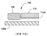
종래의 연마 패드는 전형적으로 폴리우레탄 재료들을 포함하는 폴리머 재료들을 성형, 캐스팅 또는 소결함으로써 제조된다. 성형의 경우에, 연마 패드들은 예를 들어 사출 성형에 의해 한번에 하나씩 제조될 수 있다. 캐스팅의 경우에, 액체 프리커서가 캐스팅되어 케이크로 경화되는데, 이 케이크는 후속하여 개별적인 패드 조각들로 슬라이싱된다. 그 후, 이러한 패드 조각들은 최종 두께로 기계가공될 수 있다. 슬러리 이송을 돕는 홈들을 포함하는 패드 표면 피쳐들이 사출 성형 프로세스의 일부로서 형성되거나 또는 연마 표면 내로 기계가공될 수 있다. 이러한 연마 패드들을 제조하는 방법들은 고비용이 소요되며 시간 소모적이고, 종종 패드 표면 피쳐 치수들의 생성 및 제어에서의 어려움들로 인해 불균일한 연마 결과들을 산출한다. IC 다이들 및 피쳐들의 치수들이 계속해서 축소함에 따라, 불균일성은 점점 더 중요해져 왔다.Conventional polishing pads are typically manufactured by molding, casting or sintering polymeric materials, including polyurethane materials. In the case of molding, the polishing pads can be manufactured one at a time, for example by injection molding. In the case of casting, the liquid precursor is cast and hardened into a cake, which is subsequently sliced into individual pad pieces. These pad pieces can then be machined to final thickness. Pad surface features, including grooves that aid slurry transport, may be formed as part of the injection molding process or machined into the polishing surface. Methods of manufacturing these polishing pads are expensive and time-consuming, and often produce non-uniform polishing results due to difficulties in creating and controlling pad surface feature dimensions. As the dimensions of IC dies and features continue to shrink, non-uniformity has become increasingly important.
현재의 패드 재료들 및 이들을 제조하는 방법들은 패드 성능에 있어서 중대한 역할을 하는 저장 탄성률(storage modulus)(E') 및 손실 탄성률(loss modulus)(E")과 같은 조작 및 미세 제어 벌크 패드 속성들을 제한한다. 그러므로, 균일한 CMP는, 예를 들어 약 30℃ 내지 약 90℃의 CMP 처리 온도 범위에 걸쳐 추가로 유지되는 저장 탄성률 E' 및 손실 탄성률 E"의 예측가능하고 미세하게 제어되는 밸런스를 갖는 패드 재료 및 표면 피쳐들, 예컨대 홈들 및 채널들을 요구한다. 불행하게도, 전통적인 벌크 중합 및 캐스팅 및 성형 기술들을 통한 종래의 패드 제조는 약간의 패드 속성(예를 들어, 탄성률) 제어를 제공할 뿐인데, 왜냐하면 패드는 분자내 척력과 인력 및 가변적인 폴리머 사슬 얽힘(variable polymer chain entanglement)을 겪는 상 분리된 거대분자 도메인들(phase separated macromolecular domains)의 랜덤 혼합물이기 때문이다. 예를 들어, 벌크 패드에서의 상 분리된 마이크로스코픽 및 매크로스코픽 구조 도메인들의 존재는, 기판들의 배치들(batches)의 CMP 처리 동안 전형적으로 발생하는 다수의 가열 및 냉각 사이클에 걸친 저장 탄성률 E'에서의 히스테리시스와 같은 비선형 재료 응답들의 가산적 조합(additive combination)을 산출할 수 있고, 이는 기판들의 배치에 걸쳐 연마 불균일성들 및 예측불가능한 성능을 초래할 수 있다.Current pad materials and methods for manufacturing them allow manipulating and finely controlling bulk pad properties such as storage modulus (E') and loss modulus (E"), which play critical roles in pad performance. Therefore, uniform CMP provides a predictable and finely controlled balance of storage modulus E' and loss modulus E" that is further maintained over a CMP processing temperature range of, for example, about 30° C. to about 90° C. It requires pad material and surface features such as grooves and channels. Unfortunately, conventional pad fabrication through traditional bulk polymerization and casting and molding techniques provides only little control of pad properties (e.g., elastic modulus), because pads are subject to intramolecular repulsive and attractive forces and variable polymer chain entanglements ( This is because it is a random mixture of phase separated macromolecular domains that undergo variable polymer chain entanglement. For example, the presence of phase-separated microscopic and macroscopic structural domains in the bulk pad determines the storage modulus E' over multiple heating and cooling cycles that typically occur during CMP processing of batches of substrates. can yield an additive combination of nonlinear material responses, such as hysteresis, which can lead to polishing unevenness and unpredictable performance across a batch of substrates.
종래의 연마 패드들 및 그들의 제조 방법들과 연관된 결점들 때문에, 패드 피쳐 기하형상의 제어, 및 패드의 재료, 화학적 및 물리적 속성들의 미세 제어를 제공하는 새로운 연마 패드 재료들, 및 연마 패드들을 제조하는 새로운 방법들이 필요하다. 이러한 개선들은 마이크로스코픽 레벨 및 매크로스코픽 레벨 둘 다에서, 예컨대 전체 기판에 걸쳐, 개선된 연마 균일성을 산출할 것으로 예상된다.Because of the drawbacks associated with conventional polishing pads and their manufacturing methods, there are new polishing pad materials, and methods for manufacturing polishing pads that provide control of pad feature geometry and fine control of the material, chemical and physical properties of the pad. New methods are needed. These improvements are expected to yield improved polishing uniformity at both microscopic and macroscopic levels, such as across the entire substrate.
본 개시내용의 실시예들은 복수의 순차적으로 형성된 층들을 포함하는 제1 연마 요소를 포함하는 연마 제품을 제공할 수 있다. 순차적으로 형성된 층들은 제1 층을 포함할 수 있고 제1 층은 제1 층이 형성되는 표면 상에 배치되는 다공성 형성제 함유 영역들의 제1 패턴, 및 제1 구조 재료 함유 영역을 포함하고, 상기 제1 구조 재료 함유 영역은 상기 표면 상에 그리고 상기 제1 패턴의 인접하게 위치된 다공성 형성제 함유 영역들 사이에 배치된다. 상기 순차적으로 형성된 층들은 또한 상기 제1 층의 표면 상에 배치되는 제2 층을 포함할 수 있고, 상기 제2 층은 상기 제1 층의 표면 상에 배치되는 다공성 형성제 함유 영역들의 제2 패턴, 및 제2 구조 재료 함유 영역을 포함하고, 상기 제2 구조 재료 함유 영역은 상기 제1 층의 표면 상에 그리고 상기 제2 패턴의 인접하게 위치된 다공성 형성제 함유 영역들 사이에 배치된다. 다공성 형성제 함유 영역들의 상기 제1 패턴 및 상기 제2 패턴은 각각 수용액에 노출될 때 분해되는 다공성 형성제 재료를 추가로 포함할 수 있고, 상기 다공성 형성제 재료는 아크릴레이트를 추가로 포함할 수 있다.Embodiments of the present disclosure may provide an abrasive article including a first abrasive element comprising a plurality of sequentially formed layers. The sequentially formed layers may include a first layer, the first layer comprising a first pattern of porosity former containing regions disposed on a surface on which the first layer is formed, and a first structural material containing region, A first structural material containing region is disposed on the surface and between adjacent porosity former containing regions of the first pattern. The sequentially formed layers may also include a second layer disposed on a surface of the first layer, the second layer comprising a second pattern of porous former-containing regions disposed on the surface of the first layer. , and a second structural material-containing region, the second structural material-containing region disposed on the surface of the first layer and between adjacent porosity former-containing regions of the second pattern. Each of the first pattern and the second pattern of porosity-containing regions may further comprise a porogen-former material that decomposes when exposed to an aqueous solution, and the porosity-former material may further comprise an acrylate. there is.
본 개시내용의 실시예들은 복수의 폴리머 층들을 순차적으로 형성하는 단계를 포함하는 연마 제품을 형성하는 방법을 추가로 제공할 수 있다. 상기 방법은 상기 연마 제품의 복수의 제1 연마 요소들의 제1 층을 형성하는 단계를 포함할 수 있고, 상기 제1 층을 형성하는 단계는 제1 층이 형성되는 표면 상에 다공성 형성제 함유 영역들의 제1 패턴을 형성하는 단계, 및 제1 구조 재료 함유 영역을 형성하는 단계를 포함하고, 상기 제1 구조 재료 함유 영역은 상기 표면 상에 그리고 상기 제1 패턴의 인접하게 위치된 다공성 형성제 함유 영역들 사이에 배치된다. 그 후 상기 복수의 제1 연마 요소들의 제2 층을 형성하는 단계를 포함할 수 있고, 상기 제2 층을 형성하는 단계는 상기 제1 층의 표면 상에 배치되고, 상기 제1 층의 표면 상에 다공성 형성제 함유 영역들의 제2 패턴을 형성하는 단계, 및 제2 구조 재료 함유 영역을 형성하는 단계를 포함하고, 상기 제2 구조 재료 함유 영역은 상기 제1 층의 표면 상에 그리고 상기 제2 패턴의 인접하게 위치된 다공성 형성제 함유 영역들 사이에 배치된다.Embodiments of the present disclosure may further provide a method of forming an abrasive product comprising sequentially forming a plurality of polymer layers. The method may include forming a first layer of a plurality of first abrasive elements of the abrasive product, wherein forming the first layer comprises forming a porous former-containing region on the surface on which the first layer is formed. forming a first pattern of, and forming a first structural material-containing region, wherein the first structural material-containing region contains a porosity former located on the surface and adjacent to the first pattern. placed between areas. thereafter forming a second layer of the plurality of first abrasive elements, wherein forming the second layer is disposed on a surface of the first layer, forming a second pattern of porosity-forming agent-containing regions on the surface of the first layer and forming a second structural material-containing region on the surface of the first layer and on the second structural material-containing region. It is disposed between adjacently located porogen-containing regions of the pattern.
본 개시내용의 실시예들은 기판의 표면을 연마하도록 구성되는 연마 표면을 갖는 연마 패드를 제공할 수 있는데, 이 연마 패드는 복수의 제1 폴리머 층들을 각각 포함하는 복수의 제1 연마 요소들 ― 상기 복수의 제1 폴리머 층들 중 적어도 하나가 상기 연마 표면을 형성함 ―; 및 복수의 제2 폴리머 층들을 각각 포함하는 하나 이상의 제2 연마 요소를 포함하고, 상기 하나 이상의 제2 연마 요소 각각의 적어도 하나의 영역이 상기 복수의 제1 연마 요소들 중 적어도 하나와 상기 연마 패드의 지지 표면 사이에 배치된다. 일부 구성에서, 상기 복수의 제1 폴리머 층들은 제1 폴리머 조성물을 포함하고, 상기 복수의 제2 폴리머 층들은 제2 폴리머 조성물을 포함한다. 상기 제1 폴리머 조성물은 제1 액적 조성물(droplet composition)로 형성될 수 있고, 상기 제2 폴리머 조성물은 제2 액적 조성물로 형성될 수 있다. 일부 실시예에서, 상기 제2 액적 조성물은 상기 제1 액적 조성물보다 더 많은 양의 수지 프리커서 조성물 재료(resin precursor composition material)를 포함할 수 있고, 상기 수지 프리커서 조성물 재료는 약 40℃ 이하, 예컨대 30℃ 이하의 유리 전이 온도(glass transition temperature)를 가질 수 있다. 일부 실시예에서, 상기 제1 액적은 상기 제2 액적 조성물보다 더 많은 양의 올리고머 및 수지 프리커서 조성물 재료를 포함하고, 상기 올리고머 및 수지 프리커서 조성물 재료는 2 이상의 관능가(functionality)를 갖는다. 일부 실시예에서, 상기 제1 액적 조성물은 2 이상의 관능가를 갖는 올리고머 및 수지 프리커서 조성물 재료를 포함하고, 상기 제2 액적 조성물은 2 이하의 관능가를 갖는 수지 프리커서 조성물 재료를 포함한다.Embodiments of the present disclosure may provide a polishing pad having a polishing surface configured to polish a surface of a substrate, the polishing pad comprising a plurality of first polishing elements each comprising a plurality of first polymer layers, the polishing pad comprising: at least one of the plurality of first polymer layers forming the polishing surface; and one or more second polishing elements each comprising a plurality of second polymer layers, wherein at least one region of each of the one or more second polishing elements is aligned with at least one of the plurality of first polishing elements and the polishing pad. is placed between the supporting surfaces of In some configurations, the first plurality of polymer layers comprise a first polymer composition and the plurality of second polymer layers comprise a second polymer composition. The first polymer composition may be formed as a first droplet composition, and the second polymer composition may be formed as a second droplet composition. In some embodiments, the second droplet composition may include a greater amount of a resin precursor composition material than the first droplet composition, wherein the resin precursor composition material has a temperature of about 40° C. or lower, For example, it may have a glass transition temperature of 30°C or lower. In some embodiments, the first droplet comprises a greater amount of oligomeric and resinous precursor composition material than the second droplet composition, and the oligomeric and resinous precursor composition material has a functionality of 2 or greater. In some embodiments, the first droplet composition includes oligomer and resin precursor composition material having a functionality of 2 or greater, and the second droplet composition includes a resin precursor composition material having a functionality of 2 or less.
본 개시내용의 실시예들은 기판의 표면을 연마하도록 구성되는 연마 표면을 갖는 연마 패드를 추가로 제공할 수 있는데, 이 연마 패드는 제1 폴리머 재료를 포함하는 복수의 제1 폴리머 층들을 각각 포함하는 복수의 제1 연마 요소들 ― 상기 복수의 제1 폴리머 층들 중 적어도 하나가 상기 연마 표면을 형성함 ―; 및 상기 복수의 제1 연마 요소들 중 적어도 하나와 상기 연마 패드의 지지 표면 사이에 배치되는 베이스 영역을 포함하고, 상기 베이스 영역은, 제1 수지 프리커서 조성물 재료의 복수의 경화된 액적들(cured droplets) 및 제2 수지 프리커서 조성물 재료의 복수의 경화된 액적들을 각각 포함하는 복수의 층들을 포함한다.Embodiments of the present disclosure may further provide a polishing pad having a polishing surface configured to polish a surface of a substrate, the polishing pad comprising a plurality of first polymer layers each comprising a first polymer material. a plurality of first polishing elements, at least one of the plurality of first polymer layers forming the polishing surface; and a base region disposed between at least one of the plurality of first polishing elements and a support surface of the polishing pad, the base region comprising a plurality of cured droplets of a first resin precursor composition material. droplets) and a plurality of layers each comprising a plurality of cured droplets of a second resin precursor composition material.
본 개시내용의 실시예들은 연마 제품을 형성하는 방법을 추가로 제공할 수 있는데, 이 방법은 복수의 우레탄 아크릴레이트 폴리머 층들을 형성하는 단계를 포함하고, 상기 복수의 우레탄 아크릴레이트 폴리머 층들을 형성하는 단계는 제1 재료 조성물을 포함하는 연마 바디의 표면에 걸쳐 제1 패턴으로 제1 프리커서 제제의 복수의 액적들을 분배하는 단계 ― 상기 제1 프리커서 제제는 제1 다관능성 우레탄 아크릴레이트 올리고머, 제1 양의 제1 다관능성 아크릴레이트 프리커서, 및 제1 양의 제1 경화제를 포함함 ―, 상기 연마 바디의 표면에 걸쳐 제2 패턴으로 제2 프리커서 제제의 복수의 액적들을 분배하는 단계 ― 상기 제2 프리커서 제제는 상기 제1 다관능성 우레탄 아크릴레이트 올리고머 및/또는 상기 제1 다관능성 아크릴레이트 프리커서를 포함함 ―, 및 상기 제1 프리커서 제제의 액적들 및 상기 제2 프리커서 제제의 액적들을 부분적으로만 경화시키기 위해 제1 시간 기간 동안 상기 제1 프리커서 제제의 분배된 액적들 및 상기 제2 프리커서 제제의 분배된 액적들을 전자기 복사에 노출시키는 단계를 포함한다.Embodiments of the present disclosure may further provide a method of forming an abrasive article, the method comprising forming a plurality of urethane acrylate polymer layers, forming the plurality of urethane acrylate polymer layers. The step includes dispensing a plurality of droplets of a first precursor agent in a first pattern across the surface of an abrasive body comprising a first material composition, wherein the first precursor agent comprises a first multifunctional urethane acrylate oligomer, dispensing a plurality of droplets of a second precursor formulation comprising an amount of a first multifunctional acrylate precursor, and a first amount of a first curing agent in a second pattern across the surface of the polishing body. the second precursor formulation comprising the first multifunctional urethane acrylate oligomer and/or the first polyfunctional acrylate precursor, and droplets of the first precursor formulation and the second precursor formulation. exposing the dispensed droplets of the first precursor agent and the dispensed droplets of the second precursor agent to electromagnetic radiation for a first period of time to only partially cure the droplets.
본 개시내용의 실시예들은 기판의 표면을 연마하도록 구성된 연마 표면을 갖는 연마 제품을 제공할 수 있는데, 이 연마 제품은 복수의 제1 폴리머 층들을 각각 포함하는 복수의 제1 연마 요소들-상기 복수의 제1 폴리머 층들 중 적어도 하나가 상기 연마 표면을 형성함-, 및 복수의 제2 폴리머 층들을 각각 포함하는 하나 이상의 제2 연마 요소를 포함하고, 상기 하나 이상의 제2 연마 요소 각각의 적어도 하나의 영역이 복수의 제1 연마 요소들 중 적어도 하나와 상기 연마 제품의 지지 표면 사이에 배치되고, 상기 복수의 제1 폴리머 층들은 제1 폴리머 조성물을 포함하고, 상기 복수의 제2 폴리머 층들은 제2 폴리머 조성물을 포함하고, 상기 복수의 제1 연마 요소들은 각각 노출된 부분 및 노출되지 않은 부분을 갖고, 상기 제1 연마 요소들의 노출되지 않은 부분은 상기 하나 이상의 제2 연마 요소의 부분 내에 배치되고, 상기 노출된 부분은 상기 연마 표면을 포함하는 노출 표면 면적 및 노출 표면 면적 대 체적 비율을 갖고, 상기 노출 표면 면적 대 체적 비율은 약 20mm-1 미만이다. 일부 구성에서, 상기 노출 표면 면적 대 체적 비율은 약 15mm-1 미만, 또는 약 10mm-1 미만이다.Embodiments of the present disclosure may provide an abrasive product having an abrasive surface configured to abrade a surface of a substrate, the abrasive product comprising a plurality of first abrasive elements each comprising a plurality of first polymer layers, the plurality of at least one of the first polymer layers forming the polishing surface, and one or more second polishing elements each comprising a plurality of second polymer layers, each of the one or more second polishing elements comprising at least one A region is disposed between at least one of a plurality of first abrasive elements and a support surface of the abrasive article, the first plurality of polymer layers comprising a first polymer composition, and the plurality of second polymer layers comprising a second polymer composition. comprising a polymer composition, wherein the plurality of first polishing elements each have an exposed portion and an unexposed portion, the unexposed portion of the first polishing elements being disposed within a portion of the one or more second polishing elements; The exposed portion has an exposed surface area including the polishing surface and an exposed surface area to volume ratio, wherein the exposed surface area to volume ratio is less than about 20 mm -1 . In some configurations, the exposed surface area to volume ratio is less than about 15 mm -1 , or less than about 10 mm -1 .
본 개시내용의 실시예들은 기판의 표면을 연마하도록 구성된 연마 표면을 갖는 연마 제품을 추가로 제공할 수 있는데, 이 연마 제품은 복수의 제1 폴리머 층들을 각각 포함하는 복수의 제1 연마 요소들 ― 상기 복수의 제1 폴리머 층들 중 적어도 하나가 상기 연마 표면을 형성함 ―, 및 복수의 제2 폴리머 층들을 각각 포함하는 하나 이상의 제2 연마 요소를 포함하고, 상기 하나 이상의 제2 연마 요소 각각의 적어도 하나의 영역이 상기 복수의 제1 연마 요소들 중 적어도 하나와 상기 연마 제품의 지지 표면 사이에 배치되고, 상기 복수의 제1 폴리머 층들은 제1 폴리머 조성물을 포함하고 상기 복수의 제2 폴리머 층들은 제2 폴리머 조성물을 포함하고, 상기 연마 표면에서의 상기 적어도 하나의 제1 폴리머 층은 약 60° 미만의 동적 접촉 각도를 갖는다.Embodiments of the present disclosure may further provide an abrasive product having an abrasive surface configured to abrade a surface of a substrate, the abrasive product comprising a plurality of first abrasive elements each comprising a plurality of first polymer layers; at least one of the plurality of first polymer layers forming the polishing surface, and one or more second polishing elements each comprising a plurality of second polymer layers, each of the one or more second polishing elements comprising: A region is disposed between at least one of the plurality of first abrasive elements and a support surface of the abrasive article, the first plurality of polymer layers comprising a first polymer composition and the plurality of second polymer layers and a second polymer composition, wherein the at least one first polymer layer at the polishing surface has a dynamic contact angle of less than about 60°.
본 개시내용의 실시예들은 기판의 표면을 연마하도록 구성된 연마 표면을 갖는 연마 제품를 추가로 제공할 수 있는데, 이 연마 제품은 복수의 제1 폴리머 층들을 각각 포함하는 복수의 제1 연마 요소들 ― 상기 복수의 제1 폴리머 층들 중 적어도 하나가 상기 연마 표면을 형성함 ―; 및 복수의 제2 폴리머 층들을 각각 포함하는 하나 이상의 제2 연마 요소를 포함하고, 상기 하나 이상의 제2 연마 요소 각각의 적어도 하나의 영역이 상기 복수의 제1 연마 요소들 중 적어도 하나와 상기 연마 패드의 지지 표면 사이에 배치되고, 상기 복수의 제1 폴리머 층들은 제1 폴리머 조성물을 포함하고 상기 복수의 제2 폴리머 층들은 제2 폴리머 조성물을 포함하고; 상기 제2 폴리머 층들은 90 미만의 쇼어 A 경도를 갖는다.Embodiments of the present disclosure may further provide an abrasive product having an abrasive surface configured to abrade a surface of a substrate, the abrasive product comprising a plurality of first abrasive elements each comprising a plurality of first polymer layers, the abrasive article comprising: at least one of the plurality of first polymer layers forming the polishing surface; and one or more second polishing elements each comprising a plurality of second polymer layers, wherein at least one region of each of the one or more second polishing elements is aligned with at least one of the plurality of first polishing elements and the polishing pad. disposed between the support surfaces of, wherein the first plurality of polymer layers comprise a first polymer composition and the plurality of second polymer layers comprise a second polymer composition; The second polymer layers have a Shore A hardness of less than 90.
본 개시내용의 실시예들은 기판의 표면을 연마하도록 구성된 연마 표면을 갖는 연마 제품을 추가로 제공할 수 있는데, 이 연마 제품은 복수의 제1 폴리머 층들을 각각 포함하는 복수의 제1 연마 요소들 ― 상기 복수의 제1 폴리머 층들 중 적어도 하나가 상기 연마 표면을 형성함 ―, 및 복수의 제2 폴리머 층들을 각각 포함하는 하나 이상의 제2 연마 요소를 포함하고, 상기 하나 이상의 제2 연마 요소 각각의 적어도 하나의 영역이 상기 복수의 제1 연마 요소들 중 적어도 하나와 상기 연마 제품의 지지 표면 사이에 배치되고, 상기 복수의 제1 폴리머 층들은 제1 폴리머 조성물을 포함하고 상기 복수의 제2 폴리머 층들은 제2 폴리머 조성물을 포함하고, 상기 제1 폴리머 층들의 열확산율은 약 6E-6 m2/s 미만이다.Embodiments of the present disclosure may further provide an abrasive product having an abrasive surface configured to abrade a surface of a substrate, the abrasive product comprising a plurality of first abrasive elements each comprising a plurality of first polymer layers; at least one of the plurality of first polymer layers forming the polishing surface, and one or more second polishing elements each comprising a plurality of second polymer layers, each of the one or more second polishing elements comprising: A region is disposed between at least one of the plurality of first abrasive elements and a support surface of the abrasive article, the first plurality of polymer layers comprising a first polymer composition and the plurality of second polymer layers and a second polymer composition, wherein the first polymer layers have a thermal diffusivity of less than about 6E-6 m 2 /s.
본 개시내용의 실시예들은 기판의 표면을 연마하도록 구성된 연마 표면을 갖는 연마 제품을 추가로 제공할 수 있는데, 이 연마 제품은 복수의 제1 폴리머 층들을 각각 포함하는 복수의 제1 연마 요소들 ― 상기 복수의 제1 폴리머 층들 중 적어도 하나가 상기 연마 표면을 형성함 ―, 및 복수의 제2 폴리머 층들을 각각 포함하는 하나 이상의 제2 연마 요소를 포함하고, 상기 하나 이상의 제2 연마 요소 각각의 적어도 하나의 영역이 상기 복수의 제1 연마 요소들 중 적어도 하나와 상기 연마 제품의 지지 표면 사이에 배치되고, 상기 복수의 제1 폴리머 층들은 제1 폴리머 조성물을 포함하고 상기 복수의 제2 폴리머 층들은 제2 폴리머 조성물을 포함하고; 상기 제2 폴리머 층들 중 하나 이상은 25℃와 90℃의 온도 범위 내에서 적어도 0.25 이상의 탄젠트 델타를 갖는다.Embodiments of the present disclosure may further provide an abrasive product having an abrasive surface configured to abrade a surface of a substrate, the abrasive product comprising a plurality of first abrasive elements each comprising a plurality of first polymer layers; at least one of the plurality of first polymer layers forming the polishing surface, and one or more second polishing elements each comprising a plurality of second polymer layers, each of the one or more second polishing elements comprising: A region is disposed between at least one of the plurality of first abrasive elements and a support surface of the abrasive article, the first plurality of polymer layers comprising a first polymer composition and the plurality of second polymer layers comprising a second polymer composition; One or more of the second polymer layers has a tan delta of at least 0.25 within a temperature range of 25°C and 90°C.
본 개시내용의 실시예들은 연마 제품을 형성하는 방법을 추가로 제공할 수 있는데, 이 방법은 복수의 폴리머 층들을 순차적으로 형성하는 단계를 포함하고, 상기 복수의 폴리머 층들을 형성하는 단계는: (a) 적층 제조 프로세스의 이용에 의해 표면의 제1 영역 상에 소정 양의 제1 첨가 폴리머 프리커서 제제를 분배하는 단계 ― 상기 제1 첨가 폴리머 프리커서 제제는 소정 양의 제1 첨가 폴리머 프리커서 성분 및 상기 제1 첨가 폴리머 프리커서 제제가 상기 적층 제조 프로세스를 이용하여 분배되는 것을 가능하게 하는 점도를 갖는 제2 양의 제2 첨가 폴리머 프리커서 성분을 포함함 ―; (b) 상기 적층 제조 프로세스의 이용에 의해 상기 표면의 제2 영역 상에 소정 양의 제2 첨가 폴리머 프리커서 제제를 분배하는 단계 ― 상기 제2 첨가 폴리머 프리커서 제제는 제3 양의 제3 첨가 폴리머 프리커서 성분 및 상기 제2 첨가 폴리머 프리커서 제제가 상기 적층 제조 프로세스를 이용하여 분배되는 것을 가능하게 하는 점도를 갖는 제4 양의 제4 첨가 폴리머 프리커서 성분을 포함함 ―; (c) 상기 제1 양의 제1 첨가 폴리머 프리커서 제제 및 상기 제2 양의 제2 첨가 폴리머 프리커서 제제를 부분적으로만 경화시키기 위해 제1 시간 기간 동안 상기 분배된 양의 제1 첨가 폴리머 프리커서 제제 및 상기 분배된 양의 제2 첨가 폴리머 프리커서 제제를 전자기 복사에 노출시키는 단계; 및 (d) 복수의 제1 연마 요소들을 형성하기 위해 (a)-(c)를 반복하는 단계를 포함하고, 상기 제1 연마 요소들은 각각 상기 연마 표면을 포함하는 노출 표면 면적, 및 약 20mm-1 미만인 노출 표면 면적 대 체적 비율을 갖는 노출된 부분을 갖는다.Embodiments of the present disclosure may further provide a method of forming an abrasive article, the method comprising sequentially forming a plurality of polymer layers, wherein forming the plurality of polymer layers includes: ( a) dispensing an amount of a first added polymer precursor agent onto a first region of the surface using an additive manufacturing process, wherein the first added polymer precursor agent comprises an amount of a first added polymer precursor component. and a second amount of a second added polymer precursor component having a viscosity that allows the first added polymer precursor formulation to be dispensed using the additive manufacturing process; (b) dispensing an amount of a second added polymer precursor agent onto a second region of the surface using the additive manufacturing process, wherein the second added polymer precursor agent comprises a third amount of a third added polymer precursor agent. comprising a fourth amount of a fourth added polymer precursor component having a viscosity that allows the polymer precursor component and the second added polymer precursor formulation to be dispensed using the additive manufacturing process; (c) said dispensed amount of said first added polymer precursor agent over a first period of time to only partially cure said first amount of first added polymer precursor agent and said second amount of second added polymer precursor agent. exposing the cursor formulation and the dispensed amount of the second added polymer precursor formulation to electromagnetic radiation; and (d) repeating (a)-(c) to form a plurality of first abrasive elements, each of the first abrasive elements having an exposed surface area comprising the abrasive surface, and about 20 mm - It has an exposed portion having an exposed surface area to volume ratio of less than 1 .
본 개시내용의 실시예들은 연마 제품을 형성하는 방법을 추가로 제공할 수 있는데, 이 방법은 복수의 폴리머 층들을 순차적으로 형성하는 단계를 포함하고, 상기 복수의 폴리머 층들을 형성하는 단계는 복수의 제1 연마 요소들을 형성하는 단계로서, (a) 적층 제조 프로세스의 이용에 의해 표면의 제1 영역 상에 제1 양의 제1 첨가 폴리머 프리커서 제제를 분배하는 단계 ― 상기 제1 첨가 폴리머 프리커서 제제는 소정 양의 제1 첨가 폴리머 프리커서 성분 및 상기 제1 첨가 폴리머 프리커서 제제가 상기 적층 제조 프로세스를 이용하여 분배되는 것을 가능하게 하는 점도를 갖는 제2 양의 제2 첨가 폴리머 프리커서 성분을 포함함-; (b) 상기 적층 제조 프로세스의 이용에 의해 상기 표면의 제2 영역 상에 제2 양의 제2 첨가 폴리머 프리커서 제제를 분배하는 단계 ― 상기 제2 첨가 폴리머 프리커서 제제는 제3 양의 제3 첨가 폴리머 프리커서 성분 및 상기 제2 첨가 폴리머 프리커서 제제가 상기 적층 제조 프로세스를 이용하여 분배되는 것을 가능하게 하는 점도를 갖는 제4 양의 제4 첨가 폴리머 프리커서 성분을 포함함 ―; (c) 상기 제1 양의 제1 첨가 폴리머 프리커서 제제 및 상기 제2 양의 제2 첨가 폴리머 프리커서 제제를 부분적으로만 경화시키기 위해 제1 시간 기간 동안 상기 분배된 제1 양의 제1 첨가 폴리머 프리커서 제제 및 상기 분배된 제2 양의 제2 첨가 폴리머 프리커서 제제를 전자기 복사에 노출시키는 단계; 및 (d) (a)-(c)를 반복하는 단계를 포함하는 단계; 및 제2 연마 요소를 형성하는 단계로서, (e) 적층 제조 프로세스의 이용에 의해 상기 표면의 제3 영역 상에 제3 양의 제1 첨가 폴리머 프리커서 제제를 분배하는 단계; (f) 상기 적층 제조 프로세스의 이용에 의해 상기 표면의 제4 영역 상에 제4 양의 제2 첨가 폴리머 프리커서 제제를 분배하는 단계; (g) 상기 제3 양의 제1 첨가 폴리머 프리커서 제제 및 상기 제4 양의 제2 첨가 폴리머 프리커서 제제를 부분적으로만 경화시키기 위해 제2 시간 기간 동안 상기 분배된 제3 양의 제1 첨가 폴리머 프리커서 제제 및 상기 분배된 제4 양의 제2 첨가 폴리머 프리커서 제제를 전자기 복사에 노출시키는 단계; 및 (h) (e)-(g)를 반복하는 단계를 포함하는 단계를 포함하고; 상기 형성된 제1 연마 요소들은 각각 연마 표면을 포함하는 노출 표면 면적을 갖는 노출된 부분을 갖는다.Embodiments of the present disclosure may further provide a method of forming an abrasive article, the method comprising sequentially forming a plurality of polymer layers, wherein forming the plurality of polymer layers comprises a plurality of polymer layers. Forming first abrasive elements, comprising: (a) dispensing a first amount of a first added polymer precursor formulation onto a first region of the surface by using an additive manufacturing process, said first added polymer precursor The formulation comprises an amount of a first added polymer precursor component and a second amount of a second added polymer precursor component having a viscosity that allows the first added polymer precursor formulation to be dispensed using the additive manufacturing process. Contains-; (b) dispensing a second amount of a second added polymer precursor agent onto a second region of the surface by using the additive manufacturing process, wherein the second added polymer precursor agent is a third amount of the third added polymer precursor agent. comprising a fourth amount of a fourth additive polymer precursor component having a viscosity that allows the additive polymer precursor component and the second additive polymer precursor formulation to be dispensed using the additive manufacturing process; (c) a first addition of the first amount dispensed over a first period of time to only partially cure the first amount of the first added polymer precursor agent and the second amount of the second added polymer precursor agent. exposing the polymer precursor agent and the dispensed second amount of the second added polymer precursor agent to electromagnetic radiation; and (d) repeating (a)-(c); and forming a second abrasive element, comprising: (e) dispensing a third amount of a first additive polymer precursor formulation onto a third region of the surface using an additive manufacturing process; (f) dispensing a fourth amount of a second additive polymer precursor agent onto a fourth region of the surface using the additive manufacturing process; (g) the first addition of the third amount dispensed over a second period of time to only partially cure the third amount of the first added polymer precursor agent and the fourth amount of the second added polymer precursor agent. exposing the polymer precursor agent and the dispensed fourth amount of the second added polymer precursor agent to electromagnetic radiation; and (h) repeating (e)-(g); The formed first polishing elements each have an exposed portion having an exposed surface area comprising a polishing surface.
본 개시내용의 실시예들은 연마 제품을 형성하는 방법을 추가로 제공할 수 있는데, 이 방법은 연마 바디의 일부의 표면 상에 제1 액체의 제1 액적을 분배하는 단계 ― 상기 표면은 소정 양의 제1 액체를 경화시킴으로써 형성된 제1 재료를 포함함 ―; 및 상기 제1 액적 내의 재료를 부분적으로만 경화시키기 위해 제1 시간 기간 동안 상기 제1 액체의 분배된 제1 액적을 전자기 복사에 노출시키는 단계를 포함하고, 상기 제1 액체의 분배된 제1 액적을 노출시키는 단계는 제2 시간 기간이 경과한 후에 발생하고, 상기 제2 시간은 상기 제1 액적이 상기 표면 상에 배치될 때에 시작된다. 상기 제1 액적은 우레탄 아크릴레이트, 표면 경화 광개시제(surface cure photoinitiator) 및 벌크 경화 광개시제(bulk cure photoinitiator)를 포함할 수 있고, 상기 벌크 경화 광개시제는 벤조인 에테르, 벤질 케탈, 아세틸 페논, 알킬 페논, 및 포스핀 옥사이드로 구성된 그룹으로부터 선택되는 재료를 포함하고, 상기 표면 경화 광개시제는 벤조페논 화합물 및 티오크산톤 화합물로 구성된 그룹으로부터 선택되는 재료를 포함한다.Embodiments of the present disclosure may further provide a method of forming an abrasive article, the method comprising dispensing a first droplet of a first liquid onto a surface of a portion of an abrasive body, wherein the surface is subjected to a predetermined amount of abrasive body. comprising a first material formed by curing a first liquid; and exposing the dispensed first droplet of the first liquid to electromagnetic radiation for a first period of time to only partially cure the material within the first liquid droplet. Exposing the droplet occurs after a second period of time has elapsed, the second time period beginning when the first droplet is disposed on the surface. The first droplet may include urethane acrylate, a surface cure photoinitiator, and a bulk cure photoinitiator, and the bulk cure photoinitiator may include benzoin ether, benzyl ketal, acetyl phenone, alkyl phenone, and phosphine oxide, wherein the surface curing photoinitiator includes a material selected from the group consisting of benzophenone compounds and thioxanthone compounds.
본 개시내용의 실시예들은 기판의 표면을 연마하도록 구성되는 연마 표면을 갖는 연마 패드를 추가로 제공할 수 있는데, 이 연마 패드는 상기 연마 표면에 대해 소정 패턴으로 배치되는 복수의 제1 연마 요소들 ― 각각의 제1 연마 요소는 제1 폴리머 재료를 포함하는 복수의 제1 폴리머 층들을 포함하고, 상기 제1 연마 요소들 각각에서 상기 복수의 제1 폴리머 층들 중 적어도 하나가 상기 연마 표면의 일부를 형성함 ―; 및 상기 복수의 제1 연마 요소들 중 적어도 하나와 상기 연마 패드의 지지 표면 사이에 배치되는 베이스 영역을 포함하고, 상기 베이스 영역은 제2 폴리머 재료를 포함한다. 상기 제1 폴리머 재료는 제1 E'30/E'90 비율을 가질 수 있고 상기 제2 폴리머 재료는 상기 제1 E'30/E'90 비율과 상이한 제2 E'30/E'90 비율을 가질 수 있다. 상기 베이스 영역은 각각이 상기 제1 폴리머 재료의 복수의 경화된 액적들 및 제2 폴리머 재료의 복수의 경화된 액적들을 포함하는 복수의 층들을 포함할 수 있다. 상기 제1 폴리머 재료의 상기 제1 폴리머 층들 각각은 제1 액적 조성물의 복수의 경화된 액적들을 포함할 수 있다. 일부 구성에서, 상기 제1 폴리머 재료는 6보다 큰 제1 E'30/E'90 비율을 갖는다. 상기 연마 패드 내의 상기 제1 폴리머 재료는 제1 저장 탄성률을 가질 수 있고, 상기 제2 폴리머 재료는 제2 저장 탄성률을 가질 수 있고, 상기 제1 저장 탄성률은 상기 제2 저장 탄성률보다 크고, 상기 베이스 영역은 상기 제1 폴리머 재료에 비해 더 큰 체적 퍼센트(volume percent)의 상기 제2 폴리머 재료를 추가로 포함할 수 있다. 일부 실시예에서, 상기 제1 연마 요소는 상기 제2 폴리머 재료에 비해 더 큰 체적 퍼센트의 상기 제1 폴리머 재료를 추가로 포함할 수 있다.Embodiments of the present disclosure may further provide a polishing pad having a polishing surface configured to polish a surface of a substrate, the polishing pad comprising a plurality of first polishing elements disposed in a pattern relative to the polishing surface. - each first polishing element comprises a plurality of first polymer layers comprising a first polymer material, and in each of the first polishing elements at least one of the plurality of first polymer layers forms a portion of the polishing surface. Formed -; and a base region disposed between at least one of the plurality of first polishing elements and a support surface of the polishing pad, the base region comprising a second polymer material. The first polymeric material may have a first E'30/E'90 ratio and the second polymeric material may have a second E'30/E'90 ratio that is different from the first E'30/E'90 ratio. You can have it. The base region can include a plurality of layers, each comprising a plurality of cured droplets of the first polymer material and a plurality of cured droplets of the second polymer material. Each of the first polymer layers of the first polymer material can include a plurality of cured droplets of the first droplet composition. In some configurations, the first polymer material has a first E'30/E'90 ratio greater than 6. The first polymeric material in the polishing pad can have a first storage modulus, the second polymeric material can have a second storage modulus, the first storage modulus is greater than the second storage modulus, and the base The region may further include a greater volume percent of the second polymeric material compared to the first polymeric material. In some embodiments, the first abrasive element can further include a greater volume percentage of the first polymeric material compared to the second polymeric material.
위에서 언급된 본 개시내용의 특징들이 상세하게 이해될 수 있도록, 위에 간략하게 요약된 본 개시내용의 더 구체적인 설명은 실시예들을 참조할 수 있으며, 그들 중 일부는 첨부 도면들에 예시되어 있다. 그러나, 첨부 도면들은 본 개시내용의 전형적인 실시예들만을 예시하고, 따라서 그것의 범위를 제한하는 것으로 간주되어서는 안 되며, 동등한 효과의 다른 실시예들을 인정할 수 있다는 점에 주목해야 한다.
도 1a는 연마 스테이션의 개략적인 단면도이다.
도 1b 내지 도 1e는 도 1a에 예시된 연마 스테이션 내에 위치되는 연마 헤드 및 연마 패드 구성의 일부의 개략적인 단면도들이다.
도 1f 및 도 1g는 본 개시내용의 실시예에 따른 도 1a에 예시된 연마 스테이션 내에 위치되는 연마 헤드 및 연마 패드 구성의 일부의 개략적인 단면도이다.
도 1h는 도 1b 및 도 1c에 예시된 연마 스테이션 구성을 이용하여 연마되고 있는 기판의 일부의 개략적인 단면도이다.
도 1i는 도 1d 및 도 1e에 예시된 연마 스테이션 구성을 이용하여 연마되고 있는 기판의 일부의 개략적인 단면도이다.
도 1j는 본 개시내용의 실시예에 따른 도 1f 및 도 1g에 예시된 연마 스테이션 구성을 이용하여 연마되고 있는 기판의 일부의 개략적인 단면도이다.
도 2a는 본 개시내용의 실시예에 따른 연마 패드의 개략적인 등축 단면도이다.
도 2b는 본 개시내용의 실시예에 따른 연마 패드의 개략적인 부분 상면도이다.
도 2c는 본 개시내용의 실시예에 따른 연마 패드의 개략적인 등축 단면도이다.
도 2d는 본 개시내용의 실시예에 따른 연마 패드의 일부의 개략적인 측단면도이다.
도 2e는 본 개시내용의 실시예에 따른 연마 패드의 일부의 개략적인 측단면도이다.
도 2f 내지 도 2k는 본 개시내용의 실시예들에 따른 연마 패드 설계들의 상면도들이다.
도 3a는 본 개시내용의 실시예에 따른 진보된 연마 패드들을 제조하기 위한 시스템의 개략도이다.
도 3b는 본 개시내용의 실시예에 따른 도 3a에 예시된 시스템의 일부의 개략도이다.
도 3c는 본 개시내용의 실시예에 따른 도 3b에 예시된 진보된 연마 패드의 소정 영역의 표면 상에 배치되는 분배된 액적의 개략도이다.
도 3d는 본 개시내용의 실시예에 따른 진보된 연마 패드들을 제조하기 위한 시스템에서 사용되는 노즐 어셈블리의 개략도이다.
도 4a 내지 도 4d는 본 개시내용의 적어도 하나의 실시예에 따른 진보된 연마 패드를 형성하는 데 사용되는 픽셀 차트들의 상면도들이다.
도 4e는 본 개시내용의 실시예에 따른 웹 또는 롤-투-롤 타입 연마 패드의 개략적인 상면도이다.
도 4f는 본 개시내용의 실시예에 따른 연마 패드의 일부의 개략적인 측단면도이다.
도 5a는 본 개시내용의 적어도 하나의 실시예에 따른, 공극들을 함유할 수 있는 진보된 연마 패드를 형성하는 데 사용되는 픽셀 차트의 상면도이다.
도 5b는 본 개시내용의 실시예에 따른 진보된 연마 패드의 일부의 개략적인 측단면도이다.
도 5c는 본 개시내용의 실시예에 따른 진보된 연마 패드의 일부의 개략적인 측단면도이다.
도 6a는 본 개시내용의 실시예에 따른 진보된 연마 패드를 형성하는 데 사용되는 다양한 패드 재료들에 대한 재료 경도 대비 연마된 재료 제거율의 플롯을 예시한다.
도 6b는 본 개시내용의 실시예에 따른 연마된 기판의 반경 방향 위치 대비 연마된 재료 제거율의 플롯을 예시한다.
도 6c는 본 개시내용의 실시예에 따른 연마 패드의 피쳐 높이 대비 연마된 재료 제거율의 플롯을 예시한다.
도 6d는 본 개시내용의 실시예에 따른 연마 패드의 피쳐 높이 대비 표면 면적 대 체적 비율의 플롯을 예시한다.
도 6e는 본 개시내용의 실시예에 따른 연마 패드의 개략적인 단면도이다.
도 6f는 본 개시내용의 실시예에 따른 연마 패드의 개략적인 단면도이다.
도 6g는 본 개시내용의 실시예에 따른 진보된 연마 패드에 형성된 제1 연마 요소들의 퍼센트 접촉 면적 대비 연마된 재료 제거율의 플롯을 예시한다.
도 6h는 본 개시내용의 실시예에 따른 진보된 연마 패드에 형성된 제1 연마 요소들의 퍼센트 접촉 면적 대비 연마 패드 온도의 플롯을 예시한다.
도 7a는 본 개시내용의 실시예에 따른 진보된 연마 패드 및 다양한 재료들에 대한 온도 대비 탄젠트 델타의 플롯을 예시한다.
도 7b는 본 개시내용의 실시예에 따른 진보된 연마 패드에 사용될 수 있는 재료들에 대한 변형률 대비 응력의 플롯을 예시한다.
도 7c는 본 개시내용의 실시예에 따른 연마 시스템에서 주기적 처리를 받는 패드 재료들에 대한 온도 대비 저장 탄성률의 변화의 플롯을 예시한다.
도 8a는 본 개시내용의 실시예에 따른 진보된 연마 패드 및 다양한 재료들에 대한 온도 대비 탄젠트 델타의 플롯을 예시한다.
도 8b 및 도 8c는 각각 본 개시내용의 실시예에 따른 진보된 연마 패드의 부분들의 개략적인 측단면도들이다.
도 9는 본 개시내용의 실시예에 따른 연마 패드의 일부의 개략적인 측단면도이다.
도 10은 본 개시내용의 실시예에 따른 투명 영역이 내부에 형성되어 있는 연마 패드의 개략적인 측단면도이다.
도 11은 본 개시내용의 실시예에 따른 지지 발포체 층(supporting foam layer)을 포함하는 연마 패드의 개략적인 단면 사시도이다.
이해를 용이하게 하기 위해서, 가능한 경우에, 도면들에 공통인 동일한 요소들을 지시하는 데에 공통 단어들이 이용되었다. 일 실시예에 개시된 요소들은 구체적인 언급 없이도 다른 실시예들에서 유익하게 이용될 수 있을 것으로 고려된다.In order that the above-mentioned features of the present disclosure may be understood in detail, a more detailed description of the present disclosure briefly summarized above may refer to embodiments, some of which are illustrated in the accompanying drawings. However, it should be noted that the accompanying drawings illustrate only exemplary embodiments of the present disclosure, and therefore should not be considered limiting its scope, and other embodiments of equivalent effect may be recognized.
1A is a schematic cross-sectional view of a polishing station.
1B-1E are schematic cross-sectional views of a portion of the polishing head and polishing pad configuration located within the polishing station illustrated in FIG. 1A.
1F and 1G are schematic cross-sectional views of a portion of a polishing head and polishing pad configuration located within the polishing station illustrated in FIG. 1A according to an embodiment of the present disclosure.
1H is a schematic cross-sectional view of a portion of a substrate being polished using the polishing station configuration illustrated in FIGS. 1B and 1C.
1I is a schematic cross-sectional view of a portion of a substrate being polished using the polishing station configuration illustrated in FIGS. 1D and 1E.
FIG. 1J is a schematic cross-sectional view of a portion of a substrate being polished using the polishing station configuration illustrated in FIGS. 1F and 1G according to an embodiment of the present disclosure.
2A is a schematic isometric cross-sectional view of a polishing pad according to an embodiment of the present disclosure.
2B is a schematic partial top view of a polishing pad according to an embodiment of the present disclosure.
2C is a schematic isometric cross-sectional view of a polishing pad according to an embodiment of the present disclosure.
2D is a schematic cross-sectional side view of a portion of a polishing pad according to an embodiment of the present disclosure.
2E is a schematic cross-sectional side view of a portion of a polishing pad according to an embodiment of the present disclosure.
2F-2K are top views of polishing pad designs according to embodiments of the present disclosure.
3A is a schematic diagram of a system for manufacturing advanced polishing pads according to an embodiment of the present disclosure.
FIG. 3B is a schematic diagram of a portion of the system illustrated in FIG. 3A according to an embodiment of the present disclosure.
FIG. 3C is a schematic diagram of dispensed droplets disposed on the surface of a region of the advanced polishing pad illustrated in FIG. 3B according to an embodiment of the present disclosure.
3D is a schematic diagram of a nozzle assembly used in a system for manufacturing advanced polishing pads in accordance with an embodiment of the present disclosure.
4A-4D are top views of pixel charts used to form an advanced polishing pad according to at least one embodiment of the present disclosure.
4E is a schematic top view of a web or roll-to-roll type polishing pad according to an embodiment of the present disclosure.
4F is a schematic cross-sectional side view of a portion of a polishing pad according to an embodiment of the present disclosure.
FIG. 5A is a top view of a pixel chart used to form an advanced polishing pad that may contain voids, according to at least one embodiment of the present disclosure.
5B is a schematic cross-sectional side view of a portion of an advanced polishing pad according to an embodiment of the present disclosure.
5C is a schematic cross-sectional side view of a portion of an advanced polishing pad according to an embodiment of the present disclosure.
6A illustrates a plot of polished material removal rate versus material hardness for various pad materials used to form an advanced polishing pad in accordance with an embodiment of the present disclosure.
FIG. 6B illustrates a plot of polished material removal rate versus radial position of a polished substrate according to an embodiment of the present disclosure.
FIG. 6C illustrates a plot of polished material removal rate versus feature height of a polishing pad according to an embodiment of the present disclosure.
6D illustrates a plot of surface area to volume ratio versus feature height for a polishing pad according to an embodiment of the present disclosure.
Figure 6E is a schematic cross-sectional view of a polishing pad according to an embodiment of the present disclosure.
6F is a schematic cross-sectional view of a polishing pad according to an embodiment of the present disclosure.
FIG. 6G illustrates a plot of polished material removal rate versus percent contact area of first polishing elements formed in an advanced polishing pad according to an embodiment of the present disclosure.
FIG. 6H illustrates a plot of polishing pad temperature versus percent contact area of first polishing elements formed in an advanced polishing pad according to an embodiment of the present disclosure.
7A illustrates a plot of tan delta versus temperature for an advanced polishing pad and various materials in accordance with an embodiment of the present disclosure.
FIG. 7B illustrates a plot of stress versus strain for materials that may be used in advanced polishing pads according to embodiments of the present disclosure.
FIG. 7C illustrates a plot of change in storage modulus versus temperature for pad materials subjected to cyclic processing in a polishing system according to an embodiment of the present disclosure.
8A illustrates a plot of tan delta versus temperature for an advanced polishing pad and various materials in accordance with an embodiment of the present disclosure.
8B and 8C are schematic cross-sectional side views, respectively, of portions of an advanced polishing pad according to an embodiment of the present disclosure.
9 is a schematic cross-sectional side view of a portion of a polishing pad according to an embodiment of the present disclosure.
Figure 10 is a schematic side cross-sectional view of a polishing pad with a transparent area formed therein according to an embodiment of the present disclosure.
11 is a schematic cross-sectional perspective view of a polishing pad including a supporting foam layer according to an embodiment of the present disclosure.
To facilitate understanding, where possible, common words have been used to refer to identical elements that are common to the drawings. It is contemplated that elements disclosed in one embodiment may be beneficially used in other embodiments without specific recitation.
본 개시내용은 튜닝가능한 화학, 재료 및 구조 속성들을 갖는 진보된 연마 제품들, 또는 진보된 연마 패드들, 및 이들을 제조하는 새로운 방법들에 관한 것이다. 본 개시내용의 하나 이상의 실시예에 따르면, 개선된 속성들을 갖는 연마 패드가 3차원(3D) 프린팅 프로세스와 같은 적층 제조 프로세스에 의해 제조될 수 있는 것으로 발견되었다. 본 개시내용의 실시예들은, 관능성 폴리머, 관능성 올리고머, 모노머, 반응성 희석제, 유동 첨가제, 경화제, 광개시제, 및 경화 상승작용제(cure synergists)를 포함하지만 이에 한정되지는 않는 "수지 프리커서 성분들"을 함유하는 프리커서들, 또는 수지 프리커서 조성물로 형성되는 적어도 2가지 상이한 재료로 형성된 불연속 피쳐들(discrete features) 및 기하형상들을 갖는 진보된 연마 패드를 제공한다. 수지 프리커서 성분들은 또한 적어도 일관능성일 수 있는 관능성 폴리머, 관능성 올리고머, 및 반응성 희석제와 같은 화학적으로 활성인 재료들 및/또는 화합물들을 포함할 수 있고, 자유 라디칼, 루이스 산, 및/또는 전자기 복사에 노출될 때 중합을 겪을 수 있다. 일례로서, 진보된 연마 패드는, 적어도 하나의 수지 프리커서 조성물의 자동화된 순차적인 퇴적과, 그에 후속하는 적어도 하나의 경화 단계에 의해, 복수의 폴리머 층들로 형성될 수 있고, 여기서 각각의 층은 적어도 하나의 폴리머 조성물, 및/또는 상이한 조성물들의 영역들을 나타낼 수 있다. 일부 실시예에서, 진보된 연마 패드의 층들 및/또는 영역들은, 금속, 반금속 산화물(semimetal oxides), 탄화물, 질화물 및/또는 폴리머 입자들과 같은 적어도 하나의 충전재(filler)를 함유하는 복사 경화 폴리머(radiation cured polymer)와 같은 복합 재료 구조물을 포함할 수 있다. 일부 실시예에서, 충전재들은 연마 저항성(abrasion resistance)을 증가시키고, 마찰을 감소시키고, 마모에 저항하고, 전체 패드 또는 패드의 특정 영역들의 가교결합 및/또는 열 전도율을 증대시키기 위해 이용될 수 있다. 그러므로, 패드 바디, 및 패드 바디 위에, 상에 그리고 내에 생성된 불연속 피쳐들을 포함하는 진보된 연마 패드는 복수의 상이한 재료들 및/또는 재료 조성물들로 동시에 형성될 수 있고, 따라서 패드 아키텍쳐 및 속성들의 미크론 스케일 제어를 가능하게 할 수 있다.This disclosure relates to advanced abrasive products, or advanced polishing pads, with tunable chemical, material and structural properties, and new methods of manufacturing them. In accordance with one or more embodiments of the present disclosure, it has been discovered that a polishing pad with improved properties can be manufactured by an additive manufacturing process, such as a three-dimensional (3D) printing process. Embodiments of the present disclosure describe “resin precursor components,” including but not limited to functional polymers, functional oligomers, monomers, reactive diluents, flow additives, curing agents, photoinitiators, and cure synergists. "An advanced polishing pad having discrete features and geometries formed of at least two different materials formed from precursors containing "or resin precursor compositions. Resin precursor components may also include chemically active materials and/or compounds, such as functional polymers, functional oligomers, and reactive diluents, which may be at least monofunctional, and may contain free radicals, Lewis acids, and/or May undergo polymerization when exposed to electromagnetic radiation. As an example, an advanced polishing pad can be formed from a plurality of polymer layers by automated sequential deposition of at least one resin precursor composition, followed by at least one curing step, where each layer has: It may represent at least one polymer composition, and/or regions of different compositions. In some embodiments, the layers and/or regions of the advanced polishing pad are radiation hardened containing at least one filler such as metals, semimetal oxides, carbides, nitrides, and/or polymer particles. It may include a composite material structure such as a radiation cured polymer. In some embodiments, fillers may be used to increase abrasion resistance, reduce friction, resist abrasion, crosslink the entire pad or specific areas of the pad, and/or increase thermal conductivity. . Therefore, an advanced polishing pad comprising a pad body and discontinuous features created on, on, and within the pad body can be formed simultaneously from a plurality of different materials and/or material compositions, thus providing a variety of pad architectures and properties. It can enable micron scale control.
또한, 완전한 연마 프로세스 범위에 걸쳐 바람직한 패드 연마 속성들을 포함하는 연마 패드가 제공된다. 전형적인 연마 패드 속성들은 연마 패드의 정적 속성들 및 동적 속성들 둘 다를 포함하고, 이러한 속성들은 연마 패드 내의 개별 재료들 및 완전한 연마 패드 구조물의 복합 속성들에 의해 영향을 받는다. 진보된 연마 패드는 복수의 불연속 재료를 포함하는 영역들, 및/또는 형성된 연마 패드 내의 하나 이상의 방향에서의 재료 조성의 경사들(gradients)을 포함하는 영역들을 포함할 수 있다. 연마 프로세스 범위에 걸쳐 바람직한 연마 성능을 갖는 진보된 연마 패드를 형성하도록 조정될 수 있는 기계적 속성들의 일부의 예들은 저장 탄성률 E', 손실 탄성률 E", 경도, 항복 강도(yield strength), 극한 인장 강도(ultimate tensile strength), 연신율(elongation), 열 전도율, 제타 전위(zeta potential), 질량 밀도(mass density), 표면 장력, 푸아송 비, 파괴 인성(fracture toughness), 표면 조도(surface roughness)(Ra) 및 다른 관련 속성들을 포함하지만, 이에 제한되지는 않는다. 진보된 연마 패드 패드 내에서 조정될 수 있는 동적 속성들의 일부의 예들은 탄젠트 델타(tan δ) 저장 탄성률 비율(또는 E'30/E'90 비율), 및 다른 관련 파라미터들, 예컨대 에너지 손실 계수(energy loss factor)(KEL)를 포함할 수 있지만, 이에 제한되지는 않는다. 에너지 손실 계수(KEL)는 패드 재료의 탄성 반발 및 댐프닝 효과(elastic rebound and dampening effect)에 관련된다. KEL은 다음의 식에 의해 정의될 수 있다: , 여기서 E'는 파스칼 단위이다. KEL은 전형적으로 40℃의 온도, 및 1 또는 1.6 헤르츠(Hz)의 주파수에서 동적 기계적 분석(DMA)의 방법을 이용하여 측정된다. 달리 특정되지 않는 한, 본 명세서에 제공된 저장 탄성률 E', E'30/E'90 비율 및 퍼센트 회복률(percent recovery) 측정치들은 약 1 헤르츠(Hz)의 주파수 및 약 5℃/min의 온도 상승률(temperature ramp rate)에서 수행된 DMA 테스팅 프로세스를 이용하여 수행되었다. 패드 속성들 중 하나 이상을 제어함으로써, 개선된 연마 프로세스 성능, 개선된 연마 패드 수명, 및 개선된 연마 프로세스 반복가능성이 달성될 수 있다. 하나 이상의 이러한 속성을 나타내는 패드 구성들의 예들은 본 명세서에 논의된 하나 이상의 실시예와 함께 아래에 추가로 논의된다.Additionally, a polishing pad is provided that includes desirable pad polishing properties over the complete range of polishing processes. Typical polishing pad properties include both static and dynamic properties of the polishing pad, which are influenced by the individual materials within the polishing pad and the composite properties of the complete polishing pad structure. An advanced polishing pad may include regions comprising a plurality of discontinuous materials, and/or regions comprising gradients of material composition in one or more directions within the formed polishing pad. Some examples of mechanical properties that can be tuned to form advanced polishing pads with desirable polishing performance over a range of polishing processes include storage modulus E', loss modulus E", hardness, yield strength, ultimate tensile strength ( ultimate tensile strength, elongation, thermal conductivity, zeta potential, mass density, surface tension, Poisson's ratio, fracture toughness, surface roughness (R a ) and other related properties. Examples of some of the dynamic properties that can be tuned within an advanced polishing pad pad include the tan delta (tan δ) storage modulus ratio (or E'30/E'90 ratio), and other related parameters such as, but not limited to, the energy loss factor (KEL). The energy loss factor (KEL) is defined as the elastic rebound and dampening effects of the pad material ( elastic rebound and dampening effect). KEL can be defined by the following equation: , where E' is in pascal units. KEL is typically measured using the method of dynamic mechanical analysis (DMA) at a temperature of 40° C. and a frequency of 1 or 1.6 hertz (Hz). Unless otherwise specified, the storage modulus E', E'30/E'90 ratio and percent recovery measurements provided herein are measured at a frequency of about 1 hertz (Hz) and a temperature rise rate of about 5°C/min ( This was performed using a DMA testing process performed at a temperature ramp rate). By controlling one or more of the pad properties, improved polishing process performance, improved polishing pad life, and improved polishing process repeatability can be achieved. Examples of pad configurations exhibiting one or more of these properties are discussed further below along with one or more embodiments discussed herein.
아래에 더 상세하게 논의되는 바와 같이, 저장 탄성률 E'는 연마 결과들이 기판에 걸쳐 균일한 것을 보장하는 데에 있어서 중요한 인자이고, 따라서 연마 패드 성능에 대해 유용한 메트릭이다. 저장 탄성률 E'는 응력-변형률 곡선의 탄성 선형 부분(elastic linear portion)에서의 연신 변형률(extensional strain)로 인가된 인장 응력을 나누는 것에 의해 전형적으로 계산된다(예를 들어, 기울기 또는 Δy/Δx). 유사하게, 점성 변형률(viscous strain)에 대한 점성 응력(viscous stress)의 비율은 손실 탄성률 E"를 정의하기 위해 이용된다. 저장 탄성률 E' 및 손실 탄성률 E" 둘 다는 재료 내에서의 분자간 및 분자내 화학적 결합으로부터 기인하는 고유 재료 속성들이라는 점에 유의한다. 저장 탄성률은 재료 테스팅 기술, 예컨대 동적 기계적 분석(DMA)(예를 들어, ASTM D4065, D4440, 및 D5279)을 이용하여 원하는 온도에서 측정될 수 있다. 상이한 재료들의 속성들을 비교할 때 25℃와 40℃ 사이의 범위, 예컨대 40℃에서 단일 온도에서 재료의 저장 탄성률 E'를 측정하는 것이 전형적이다.As discussed in more detail below, storage modulus E' is an important factor in ensuring that polishing results are uniform across the substrate and is therefore a useful metric for polishing pad performance. Storage modulus E' is typically calculated by dividing the applied tensile stress by the extensional strain in the elastic linear portion of the stress-strain curve (e.g., slope or Δy/Δx). . Similarly, the ratio of viscous stress to viscous strain is used to define the loss modulus E". Both the storage modulus E' and loss modulus E" are intermolecular and intramolecular within the material. Note that these are intrinsic material properties that result from chemical bonds. Storage modulus can be measured at the desired temperature using materials testing techniques such as dynamic mechanical analysis (DMA) (e.g., ASTM D4065, D4440, and D5279). When comparing the properties of different materials it is typical to measure the storage modulus E' of the material at a single temperature in the range between 25°C and 40°C, for example at 40°C.
연마 패드 성능 및 균일성에서의 다른 관련 메트릭은 재료의 댐프닝 능력의 척도, 예컨대 연마 패드의 압축 및 반발 댐프닝 속성들의 척도이다. 댐프닝을 측정하는 일반적인 방식은 원하는 온도에서 재료의 탄젠트 델타(tan δ를 계산하는 것이고, 여기서 tan δ= 손실 탄성률/저장 탄성률 = E"/E'이다. 상이한 재료들의 속성들을 비교할 때 40℃와 같은 단일 온도에서 재료들에 대한 tan δ 측정들을 비교하는 것이 전형적이다. 달리 특정되지 않는 한, 본 명세서에 제공된 tan δ측정치들은 1 헤르츠(Hz)의 주파수 및 약 5℃/min의 온도 상승률에서 수행된 DMA 테스팅 프로세스를 이용하여 수행되었다. 일반적으로, tan δ는, 재료에서의 스프링-유사 탄성 화학 구조들(spring-like elastic chemical structures), 예컨대 힘이 해제될 때 바람직한 저 에너지 형태(conformation) 및 구조로 복귀되는 가요성의 코일형 지방족 폴리머 사슬들(flexible and coiled aliphatic polymer chains)과 비교하여, 재료 내의 "점성" 화학 구조들이 인가된 반복 변형률(cyclic strain)에 어떻게 응답하는지(예를 들어, 결합 회전(bond rotation), 폴리머 사슬 슬리피지(slippage) 및 이동)의 척도이다. 예를 들어, 재료의 탄성이 적을수록, 주기적 부하(cyclic load)가 인가될 때, 재료의 점성 분자 세그먼트들의 응답은 재료의 탄성 분자 세그먼트들에 뒤떨어질 것이고(상 시프트(phase shift)), 열이 발생된다. 기판들의 처리 동안 연마 패드에서 발생되는 열은 연마 프로세스 결과들(예를 들어, 연마 균일성)에 영향을 미칠 수 있고, 따라서 패드 재료들의 신중한 선택(judicious choice)에 의해 제어 및/또는 보상되어야 한다.Another relevant metric in polishing pad performance and uniformity is a measure of the dampening ability of the material, such as a measure of the compressive and rebound damping properties of the polishing pad. A common way to measure dampening is to calculate the material's tangent delta (tan δ) at the desired temperature, where tan δ = loss modulus/storage modulus = E"/E'. When comparing the properties of different materials, the It is typical to compare tan δ measurements for materials at the same single temperature.Unless otherwise specified, tan δ measurements provided herein are performed at a frequency of 1 hertz (Hz) and a temperature rise rate of approximately 5° C./min. was performed using the DMA testing process. In general, tan δ is determined by the spring-like elastic chemical structures in the material, such as the desired low-energy conformation and Compared to flexible and coiled aliphatic polymer chains, which return to their structure, how the “sticky” chemical structures within the material respond to applied cyclic strain (e.g., bonding). bond rotation, polymer chain slippage, and movement. For example, the less elastic a material is, the greater the response of the material's viscous molecular segments when a cyclic load is applied. The elastic molecular segments of the material will lag behind (phase shift) and heat will be generated. The heat generated in the polishing pad during processing of the substrates will affect the polishing process results (e.g. polishing uniformity). may have an impact and therefore must be controlled and/or compensated for by judicious choice of pad materials.
연마 패드 내의 재료들의 경도는 연마 후에 기판 상에서 발견되는 연마 균일성 결과들, 및 재료 제거율에 있어서 역할을 한다. 종종 로크웰(Rockwell), 볼(Ball) 또는 쇼어(Shore) 경도 스케일을 이용하여 또한 측정되는 재료의 경도는 압입(indentation)에 대한 재료 저항성을 측정하고, 경험적인 경도 값을 제공하며, 저장 탄성률 E'의 증가를 추적하거나 이러한 증가에 따라 증가할 수 있다. 전형적으로, 패드 재료들은 ASTM D2240 기술을 이용하여 전형적으로 측정되는 쇼어 경도 스케일을 이용하여 측정된다. 전형적으로, 패드 재료 경도 속성들은, 폴리올레핀과 같은 더 연질이거나 낮은 저장 탄성률 E'의 폴리머 재료들을 위해 흔하게 이용되는 쇼어 A 또는 쇼어 D 스케일로 측정된다. 로크웰 경도(예를 들어, ASTM D785) 테스팅이 또한 열가소성 및 열경화성 재료들과 같은 "경질"의 강성 엔지니어링 폴리머 재료들의 경도를 테스트하는 데 사용될 수 있다.The hardness of the materials within the polishing pad plays a role in the polishing uniformity results and material removal rate found on the substrate after polishing. The hardness of a material, often also measured using the Rockwell, Ball, or Shore hardness scales, measures the material's resistance to indentation, provides an empirical hardness value, and the storage modulus E ' can track the increase in or increase in line with this increase. Typically, pad materials are measured using the Shore hardness scale, which is typically measured using ASTM D2240 technology. Typically, pad material hardness properties are measured on the Shore A or Shore D scale, which are commonly used for softer or lower storage modulus E' polymer materials such as polyolefins. Rockwell hardness (e.g., ASTM D785) testing can also be used to test the hardness of “hard” rigid engineering polymer materials such as thermoplastics and thermosets.
연마 패드 장치 및 연마 방법Polishing pad device and polishing method
도 1a는 다수의 연마 스테이션들(100)을 포함하는 더 큰 화학 기계적 연마(CMP) 시스템 내에 위치될 수 있는 연마 스테이션(100)의 개략적인 단면도이다. 연마 스테이션(100)은 플래튼(102)을 포함한다. 플래튼(102)은 중심 축(104)을 중심으로 회전할 수 있다. 연마 패드(106)가 플래튼(102) 상에 배치될 수 있다. 전형적으로, 연마 패드(106)는 연마 스테이션(100) 내에서 처리될 기판(110)의 크기(예를 들어, 기판 직경)보다 적어도 1배 내지 2배 더 큰 플래튼(102)의 상부 표면을 커버한다. 일례에서, 연마 패드(106) 및 플래튼(102)은 직경이 약 6 인치(150mm) 내지 약 40 인치(1,016mm)이다. 연마 패드(106)는 플래튼(102)의 표면 위에 위치되는 지지 표면(103), 및 하나 이상의 기판(110)에 접촉하여 이러한 기판들을 처리하도록 구성된 연마 표면(112)을 포함한다. 플래튼(102)은 연마 동안 연마 패드(106)를 지지하며 연마 패드(106)를 회전시킨다. 캐리어 헤드(108)가 연마 패드(106)의 연마 표면(112)에 대하여 기판(110)을 유지한다. 캐리어 헤드(108)는 기판(110)을 연마 패드(106)에 대하여 압박하기 위해 이용되는 가요성 다이어프램(111), 및 연마 프로세스 동안 기판의 표면에 걸쳐 발견되는 고유하게 불균일한 압력 분포를 정정하기 위해 이용되는 리테이닝 링(109)을 전형적으로 포함한다. 캐리어 헤드(108)는 기판(110)과 연마 패드(106) 사이에 상대적인 움직임들을 발생시키기 위해 스위핑 모션으로 이동하고/하거나 중심 축(114)을 중심으로 회전할 수 있다.1A is a schematic cross-sectional view of a polishing
전달 암(118)이 연마 동안 연마 표면(112)에 공급되는 연마 유체(116), 예컨대 연마재 슬러리를 전달한다. 연마 유체(116)는 기판의 화학 기계적 연마을 가능하게 하기 위해 화학적 활성 성분들, pH 조정제 및/또는 연마재 입자들을 함유할 수 있다. 연마 유체(116)의 슬러리 화학물질은 금속들, 금속 산화물들, 및 반금속 산화물들을 포함할 수 있는 웨이퍼 표면들 및/또는 피쳐들을 연마하도록 설계된다. 전형적으로, 연마 스테이션(100)은 패드 컨디셔닝 어셈블리(120)를 또한 포함하고, 이 패드 컨디셔닝 어셈블리는 패드 컨디셔닝 디스크(128)(예를 들어, 다이아몬드 함침 디스크)가 연마 프로세스 사이클 동안 상이한 시간들에서 연마 표면(112)에 대하여 압박되고 연마 표면에 걸쳐 스위프하여, 연마 패드(106)의 표면(112)을 연마하고 회생(rejuvenate)시키게 하도록 구성되는 액추에이터들(124 및 126) 및 컨디셔닝 암(122)을 포함한다.
도 1b 및 도 1c는 연마 스테이션(100) 내에 위치되는 종래의 "경질" 또는 높은 저장 탄성률 E' 탄성률 연마 패드(106A) 및 캐리어 헤드(108)의 일부의 개략적인 단면도들이다. 도 1d 및 도 1e는 연마 스테이션(100) 내에 위치되는 종래의 연질 또는 낮은 저장 탄성률 E' 연마 패드(106B) 및 캐리어 헤드(108)의 일부의 개략적인 단면도들이다. 도 1f 및 도 1g는 연마 스테이션(100) 내에 위치되는, 아래에 추가로 설명되는, 진보된 연마 패드(200)의 일 실시예, 및 캐리어 헤드(108)의 일부의 개략적인 단면도들이다. 명료성을 위해, 캐리어 헤드(108)의 상부 부분 및 가요성 다이어프램(111)은 도 1b 내지 도 1g에서 빠져있다. 동작 동안, 가요성 다이어프램(111)(도 1a)은 기판(110)을 연마 패드(106A, 106B) 또는 진보된 연마 패드(200)에 대하여 압박하도록 위치되고, 캐리어 헤드(108)의 장착 부분(도시되지 않음)에 결합되는 캐리어 헤드 액추에이터(도시되지 않음)는 캐리어 헤드(108) 및 리테이닝 링(109)을 연마 패드(106A, 106B) 또는 진보된 연마 패드(200)의 표면에 대하여 개별적으로 압박하도록 구성된다. 도 1c, 도 1e 및 도 1f에 도시된 바와 같이, 가요성 다이어프램(111)은 인가된 힘 F2에 의해 예시되는 기판(110)의 후면에 대한 압력을 인가하도록 구성되고, 캐리어 헤드 액추에이터는 리테이닝 링(109)에 힘 F1을 인가하도록 구성된다.1B and 1C are schematic cross-sectional views of a portion of a conventional “hard” or high storage modulus E'
도 1b는 연마 프로세스가 기판(110)에 대해 수행되기 전에, 캐리어 헤드(108) 내에, 그리고 종래의 "경질" 또는 높은 저장 탄성률 E' 연마 패드(106A)의 일부 위에 위치되는 기판(110)의 에지의 일부를 예시한다. 기판(110)은 후속 CMP 프로세스 동안 제거 및/또는 평탄화될 하나 이상의 디바이스 피쳐(110B)를 갖는 층(110A)을 포함한다(도 1h). 도 1c는 도 1b에 예시된 종래의 "경질" 연마 패드(106A)를 사용한 연마 프로세스 동안의 기판(110)을 예시한다. "경질" 연마 패드들을 이용하는 CMP 프로세스들은 기판(110)의 에지에서 발견되는 에지 효과들(edge effects)로 인해 불균일한 평탄화 결과들을 갖는 경향이 있는 것으로 밝혀졌으며, 이러한 에지 효과들은 CMP 프로세스 동안 기판(110)의 에지에서 발견되는 더 큰 고유 연마 불균일성을 보상하기 위해 힘 F1을 리테이닝 링(109)에 인가할 필요성에 구체적으로 관련된다. 다시 말하면, "경질" 연마 패드를 형성하기 위해 이용되는 재료의 높은 저장 탄성률 E', 강성 또는 경질 성질은 리테이닝 링(109)에 의해 힘 F1이 "경질" 연마 패드(106A)에 인가될 때 패드 반발 또는 리지(ridge)(107A)가 형성되게 한다. 리지(107A)의 형성은 인가된 힘 F1로 인한 "경질" 연마 패드(106A)의 변형(107B)에 일반적으로 관련되고, 이는 기판(110)의 에지가 기판(110)의 중심보다 더 빠르게 연마되게 한다. 기판(110)의 에지에서의 더 높은 연마 속도는 "전역적" CMP 평탄화 불균일성(예를 들어, 기판에 걸친 불균일성)을 초래한다.1B shows a view of a
도 1h는 종래의 "경질" 연마 패드(106A)를 이용하여 연마되고 있는 기판(110)의 일부의 개략적인 단면도이다. 도시된 바와 같이, 기판(110)은, 층(110A) 내에 형성되고, CMP 프로세스 동안 제거 및/또는 평탄화되는 복수의 피쳐들(110B)을 포함한다. 이러한 예에서, "경질" 연마 패드(106A)를 형성하기 위해 이용되는 재료의 높은 저장 탄성률 E', 강성 및/또는 경질 성질은, 가요성 다이어프램(111)에 의해 힘 F2가 기판(110)에 인가될 때 이러한 패드가 마이크로스코픽 스케일(예를 들어, 10nm-1000nm 피쳐 피치)에서 상당히 변형되는 것을 허용하지 않을 것이다. 이러한 경우에, "경질" 연마 패드(106A)는 마이크로스코픽 스케일에서 허용가능한 양의 평탄화 및 평탄화 효율을 일반적으로 산출할 것이지만, 위에서 논의된 이유들로 인해 불량한 전역적 평탄화 결과들을 달성할 것이다.1H is a schematic cross-sectional view of a portion of a
도 1d는 연마 프로세스가 기판(110)에 대해 수행되기 전에, 캐리어 헤드(108) 내에, 그리고 종래의 연질 또는 낮은 저장 탄성률 E' 연마 패드(106B)의 일부 위에 위치되는 기판(110)의 에지의 일부를 예시한다. 기판(110)은 후속 CMP 프로세스 동안 제거 및 평탄화될 하나 이상의 디바이스 피쳐(110B)(도 1i)를 갖는 층(110A)을 포함한다. 도 1e는 도 1d에 예시된 종래의 연질 또는 낮은 저장 탄성률 E' 연마 패드(106B)를 사용하는 연마 프로세스 동안 기판(110)을 예시한다. 연질 또는 낮은 저장 탄성률 E' 연마 패드가 CMP 프로세스 동안 리테이닝 링(109)에 의해 발생되는 인가된 힘 F1 및 가요성 다이어프램(111)에 의해 발생되는 인가된 힘 F2 하에서 변형되는 것이 비교적 용이한 것으로 인해, 연질 또는 낮은 저장 탄성률 E' 연마 패드들을 이용하는 CMP 프로세스들은 불균일한 평탄화 결과들을 갖는 경향이 있는 것으로 밝혀졌다. 다시 말하면, 연질 또는 낮은 저장 탄성률 E' 연마 패드(106B)를 형성하기 위해 이용되는 재료의 연질, 가요성 및 낮은 저장 탄성률 E' 성질은 리테이닝 링(109)에 의해 공급되는 힘 F1이 최소화되는 효과를 허용하고, 이것은 패드가 리테이닝 링(109)의 하향력을 보상하는 능력을 개선한다. 낮은 탄성률(elastic modulus) 재료의 이러한 압축 응답(compressive response)은 리테이닝 링 압축의 신속한 회복, 및 연마 프로세스 동안 기판의 중심과 에지 사이에서 보이는 더 일관된 연마 속도를 허용한다. 그러므로, 연질 또는 낮은 저장 탄성률 E' 연마 패드의 이용은 더 전역적인 CMP 평탄화 균일성을 야기할 것이다.1D illustrates an edge of a
도 1i는 종래의 연질 또는 낮은 저장 탄성률 E' 연마 패드(106B)를 이용하여 연마되고 있는 기판의 일부의 개략적인 단면도이다. 이러한 예에서, 연질 또는 낮은 저장 탄성률 E' 연마 패드(106B)를 형성하기 위해 이용되는 재료의 가요성 또는 연질 또는 낮은 저장 탄성률 E' 성질은, 가요성 다이어프램(111)에 의해 힘 F2가 기판(110)에 인가될 때 재료가 마이크로스코픽 스케일(예를 들어, 10nm-1000nm 피쳐 피치)로 변형되는 것을 허용한다. 도 1i에 도시된 바와 같이, 연질 또는 낮은 저장 탄성률 E' 연마 패드(106B) 내의 재료는 변형되고, 후속하여 디바이스 피쳐들(110B) 사이의 층(110A)의 영역들에 접촉하여 이러한 영역들을 연마할 수 있다. 피쳐들(110B)의 최상부들 및 피쳐들(110B) 사이의 영역들의 부분들을 동시에 연마하는 동작은 평탄화 불균일성들 및 다른 평탄화 문제점들을 생성할 것이다. 이 경우, 연질 또는 낮은 저장 탄성률 E' 연마 패드(106B)는 일반적으로 허용가능한 양의 전역적 평탄화를 산출할 것이지만, 불량한 평탄화 효율을 달성하고 불량한 디싱 결과들(dishing results)을 제공할 것이다. 낮은 저장 탄성률 함유 연마 패드들은 마이크로스코픽 스케일의 개선된 스크래치 성능에서 이점을 제공하는데, 왜냐하면 이러한 연마 패드들은 패드 표면과 기판의 표면 사이에 배치될 수 있는 경질 결함들(hard defects)이 더 높은 저장 탄성률 재료에 의해 기판 표면에 대해 강제되기보다는 패드 매트릭스 내에서 압축 및/또는 수용되는 것을 허용하기 때문이다.1I is a schematic cross-sectional view of a portion of a substrate being polished using a conventional soft or low storage modulus E'
진보된 연마 패드들Advanced Polishing Pads
본 개시내용의 실시예들은 적층 제조 프로세스의 이용에 의해 형성될 수 있는 진보된 연마 패드들(200)을 일반적으로 제공한다. 진보된 연마 패드들은, 적어도 2가지 상이한 재료 조성물로 형성되는 불연속 피쳐들 또는 영역들을 전형적으로 포함하는 패드 바디를 갖는다. 도 1f 및 도 1g는 연마 스테이션(100) 내에 위치되는 진보된 연마 패드(200)의 패드 바디(202) 및 캐리어 헤드(108)의 일부의 개략적인 단면도들이다. 일반적으로, 진보된 패드의 기계적, 구조적, 및/또는 동적 속성을 개선하기 위해, 연마 프로세스 동안 인가되는 부하가 2가지 이상의 재료 조성물을 포함하는 연마 바디(202)의 영역들을 통해 분산되도록 구성되는 진보된 연마 패드(200)를 형성하는 것이 바람직하다. 일 실시예에서, 패드 바디(202)는 제1 저장 탄성률 E' 재료(예를 들어, 높은 저장 탄성률 E' 재료)로 형성되는 제1 연마 요소(204), 및 제2 저장 탄성률 E' 재료(예를 들어, 중간 또는 낮은 저장 탄성률 E' 재료)로 형성될 수 있는 제2 연마 요소(206)를 적어도 포함할 수 있다. 일 구성에서, 제1 연마 요소(204)의 상부 표면들(208)이 제2 연마 요소(들)(206) 위로 돌출되도록, 지지 표면(203)으로부터의 제1 연마 요소(들)(204)의 높이(150)는 제2 연마 요소(들)(206)의 높이(151)보다 더 높다. 일례에서, 도 1g에 도시된 바와 같이, 연마 요소들 각각에서의 재료들의 조합인 원하는 기계적 및 동적 속성들을 갖는 진보된 연마 패드를 형성하기 위해, 힘 F2가 가요성 다이어프램(111)에 의해 제1 연마 요소들(204)을 통해, 도 1a에 도시된 플래튼(102)과 같은 지지 부재에 의해 지지되는 제2 연마 요소(206)로 전달된다. 더 높은 저장 탄성률 타입의 연마 피쳐들을 낮은 저장 탄성률 타입의 지지 피쳐로부터 분리시킴으로써, 진보된 연마 패드는 더 높은 저장 탄성률의 최상부 패드에 의해 제공되는 개선된 다이 및 어레이 레벨 평면성의 이점을 유지하면서, 개선된 전역적 평면성의 이점을 제공한다.Embodiments of the present disclosure generally provide
도 1j는 본 개시내용의 실시예에 따른 진보된 연마 패드(200)를 이용하여 연마되고 있는 기판(110)의 일부의 개략적인 단면도이다. 도 1j에 예시된 바와 같이, 일부 실시예에서, 연마 바디(202) 내의 제1 연마 요소(204)는, 기판(110)의 표면 상에 형성되는 적어도 2개 이상의 디바이스 피쳐(110B)(예를 들어, 집적 회로 디바이스들)의 거리에 걸쳐질 정도로 충분히 크도록 형성된다. 일부 실시예에서, 제1 연마 요소들(204) 중 하나 이상은 기판의 주요 치수(예를 들어, 원형 기판의 반경)보다는 작지만 기판(110) 상에서 발견되는 가장 작은 디바이스 피쳐 크기보다는 크도록 크기가 정해진다. 일부 실시예에서, 복수의 제1 연마 요소들(204)은, 크기가 약 250 마이크로미터 내지 약 3mm인, 연마 표면에 평행한 측방향 치수(208L)를 각각 갖는다. 일례에서, 제1 연마 요소들(204)이 연마 표면(208)에서 원형, 정사각형, 직사각형 또는 삼각형 단면을 갖는 경우, 측방향 치수(예를 들어, 길이(208L))는 제1 연마 요소(204)의 정사각형, 직사각형 또는 삼각형 각각의 레그(leg) 또는 직경일 수 있다. 다른 예에서, 제1 연마 요소들(204)이 연마 표면(208)에서 토로이드 형상 또는 아크 형상을 갖는 경우, 측방향 치수(예를 들어, 폭(214))는 반경을 따라 측정될 때의 토로이드 또는 아크의 두께, 또는 심지어는 일부 경우들에서는 토로이드의 외측 직경일 수 있다. 따라서, 아래에 추가로 논의되는 바와 같이, 진보된 연마 패드를 이용하여 기판에 대해 수행되는 연마 프로세스의 결과들을 개선하도록 진보된 연마 패드 속성들 및 성능을 조정하기 위해 제1 연마 요소들(204) 및 하나 이상의 제2 연마 요소(206)의 조합이 이용될 수 있다.1J is a schematic cross-sectional view of a portion of a
일부 실시예에서, 진보된 연마 패드(200)는 적어도 하나의 높은 저장 탄성률 E', 매체 저장 탄성률 E', 및/또는 낮은 저장 탄성률 E' 연마 요소 및/또는 화학 구조적 피쳐를 포함할 수 있다. 예를 들어, 높은 저장 탄성률 E' 재료 조성물은 방향족 고리(aromatic ring)(들) 및 일부 지방족 사슬들을 포함하는 화학적 기들 및/또는 구조적 피쳐들 중 적어도 하나 또는 이들의 혼합물일 수 있다. 일부 경우들에서, 높은 저장 탄성률 E' 재료들은 2%보다 큰 가교결합 밀도를 갖는다. 높은 저장 탄성률 E' 조성물들은 진보된 연마 패드에서 가장 강성인 요소일 수 있고, 높은 경도 값을 가질 수 있으며, 최소 연신율을 나타낼 수 있다. 중간 저장 탄성률 E' 조성물들은 가교결합, 방향족 고리들의 혼합물을 함유할 수 있지만, 높은 저장 탄성률 E' 조성물들보다 더 많은 함량의 지방족 사슬들, 에테르 세그먼트들, 및/또는 폴리우레탄 세그먼트들을 함유할 수 있다. 중간 저장 탄성률 E' 조성물들은 중간 강성, 경도를 가질 수 있고, 높은 저장 탄성률 E' 재료들보다 더 많은 양의 연신율을 나타낼 수 있다. 낮은 저장 탄성률 E' 조성물들은 지방족 사슬들, 에테르 세그먼트들, 및/또는 폴리우레탄 세그먼트들을 함유할 수 있고, 방향족 고리들 또는 가교결합으로부터의 기여는 최소이거나 없다. 낮은 저장 탄성률 E' 조성물들은 가요성, 연질, 및/또는 고무-유사(rubber-like)일 수 있다.In some embodiments,
30℃의 온도들에서 바람직한 낮은, 중간 및/또는 높은 저장 탄성률 E' 속성들(E'30)을 갖는 재료들이 표 1에 요약되어 있다.Materials with desirable low, medium and/or high storage modulus E' properties (E'30) at temperatures of 30°C are summarized in Table 1.
<표 1><Table 1>

일 실시예에서, 그리고 표 1을 참조하면, 연마 패드 바디(202)는 상이한 저장 탄성률 E' 및/또는 손실 탄성률 E" 를 갖는 적어도 하나의 점탄성 재료로 형성될 수 있다. 그 결과, 패드 바디는 제1 저장 탄성률 E' 및 손실 탄성률 E"를 갖는 제1 재료 또는 제1 재료 조성물, 및 제1 저장 탄성률 E' 및 손실 탄성률 E"와 상이한 제2 저장 탄성률 E' 및 손실 탄성률(E")을 갖는 제2 재료 또는 제2 재료 조성물을 포함할 수 있다. 일부 실시예에서, 연마 패드 표면 피쳐들은 하나 이상의 폼 팩터 또는 치수를 갖는 복수의 피쳐들을 포함할 수 있고, 상이한 기계적, 열적, 계면적(interfacial), 및 화학적 속성들을 갖는 피쳐들의 혼합물일 수 있다. 예를 들어, 패드 바디 위에, 상에 그리고 내에 배치된 채널들, 홈들, 및/또는 돌기들과 같은 패드 표면 피쳐들은 제1 재료 또는 제1 재료 조성물로부터 도출된 더 높은 저장 탄성률 E' 속성들, 및 제1 재료 또는 제1 재료 조성물보다 더 큰 탄성을 갖는 제2 재료 또는 제2 재료 조성물로부터 도출된 일부 더 낮은 저장 탄성률 E' 속성들 둘 다를 포함할 수 있다.In one embodiment, and with reference to Table 1, polishing
본 명세서에서 사용된 진보된 연마 패드(200)라는 용어는, 위에서 논의되고 아래에 추가로 논의되는 속성들, 재료들, 피쳐들 및/또는 속성들 중 하나 이상을 포함하는 진보된 연마 패드를 광범위하게 설명하는 것으로 의도된다. 진보된 연마 패드들의 특정 구성들은 도 2a 내지 도 2k에 예시된 예들과 함께 논의된다. 달리 특정되지 않는 한, 제1 연마 요소(들)(204) 및 제2 연마 요소(들)(206)라는 용어들은 진보된 연마 패드(200)의 연마 바디 내의 부분들, 영역들, 및/또는 피쳐들을 광범위하게 설명하는 것으로 의도된다. 본 명세서에 설명된 적층 제조 프로세스들 중 하나 이상의 이용에 의해 다른 유사한 구성들이 형성될 수 있으므로, 도 2a 내지 도 2k에 도시된 상이한 진보된 연마 패드 구성들의 특정 예들은 본 명세서에 제공된 본 개시내용의 범위에 관하여 제한하는 것으로 의도되지는 않는다.As used herein, the term
진보된 연마 패드들은, 적어도 하나의 수지 프리커서 조성물의 층별의(layer by layer) 자동화된 순차적인 퇴적과, 그에 후속하는 적어도 하나의 경화 단계에 의해 형성될 수 있고, 여기서 각각의 층은 적어도 하나의 폴리머 조성물, 및/또는 상이한 조성물들의 영역들을 나타낼 수 있다. 조성물들은 관능성 폴리머들, 관능성 올리고머들, 반응성 희석제들, 및 경화제들을 포함할 수 있다. 관능성 폴리머들은 다관능성 아크릴레이트 프리커서 성분들을 포함할 수 있다. 복수의 고체 폴리머 층들을 형성하기 위해, 하나 이상의 조성물을 UV 복사 및/또는 컬럼 에너지에 노출시키는 것과 같은 하나 이상의 경화 단계가 이용될 수 있다. 이러한 방식으로, 전체 연마 패드는 3D 프린팅에 의해 복수의 폴리머 층들로 형성될 수 있다. 경화된 층의 두께는 약 0.1 미크론 내지 약 1mm, 예컨대 5 미크론 내지 약 100 미크론, 및 예컨대 25 미크론 내지 약 30 미크론일 수 있다.Advanced polishing pads can be formed by automated sequential deposition, layer by layer, of at least one resin precursor composition, followed by at least one curing step, wherein each layer has at least one polymer composition, and/or regions of different compositions. Compositions may include functional polymers, functional oligomers, reactive diluents, and curing agents. Functional polymers may contain multifunctional acrylate precursor components. To form a plurality of solid polymer layers, one or more curing steps may be used, such as exposing one or more compositions to UV radiation and/or column energy. In this way, the entire polishing pad can be formed from multiple polymer layers by 3D printing. The thickness of the cured layer can be from about 0.1 micron to about 1 mm, such as from 5 microns to about 100 microns, and such as from 25 microns to about 30 microns.
본 개시내용에 따른 연마 패드들은 연마 요소와 연마 요소 간의 적어도 하나의 조성 경사(compositional gradient)에 의해 반영된 바와 같이, 패드 바디(202)에 걸쳐, 저장 탄성률 E' 및 손실 탄성률 E"와 같은 상이한 기계적 속성들을 가질 수 있다. 연마 패드(200)에 걸친 기계적 속성들은, 정적 기계적 속성들, 동적 기계적 속성들, 및 마모 속성들을 포함할 수 있는 타겟 연마 패드 속성들을 달성하기 위해 대칭 또는 비대칭, 균일 또는 불균일할 수 있다. 패드 바디(202)에 걸친 연마 요소들(204, 206) 중 어느 하나의 패턴들은 연마 패드에 걸쳐 저장 탄성률 E' 및 손실 탄성률 E"를 포함하는 타겟 속성들을 달성하기 위해 방사형, 동심형, 직사각형, 나선형, 프랙탈 또는 랜덤일 수 있다. 유리하게는, 3D 프린팅 프로세스는 패드의 특정 패드 영역들 내에서 또는 패드의 더 큰 영역들 위에서 원하는 속성들을 갖는 재료 조성물들의 특정 배치를 가능하게 하고, 따라서 속성들은 결합되고, 속성들의 더 큰 평균 또는 속성들의 "복합물"을 표현한다.Polishing pads according to the present disclosure have different mechanical properties, such as storage modulus E' and loss modulus E", across
진보된 연마 패드 구성의 예들Examples of Advanced Polishing Pad Configurations
도 2a는 본 개시내용의 일 실시예에 따른 진보된 연마 패드(200a)의 개략적인 사시 단면도이다. 하나 이상의 제1 연마 요소(204a)는 원형 패드 바디(202)를 형성하기 위해 하나 이상의 제2 연마 요소(206a)에 결합되는 교대하는 동심 링들(alternating concentric rings)로 형성될 수 있다. 일 실시예에서, 제1 연마 요소(들)(204a)의 상부 표면들(208)이 제2 연마 요소(들)(206a) 위로 돌출되도록, 지지 표면(203)으로부터의 제1 연마 요소(들)(204a)의 높이(210)는 제2 연마 요소(들)(206a)의 높이(212)보다 더 높다. 일 실시예에서, 제1 연마 요소(204)는 제2 연마 요소(들)(206a)의 부분(212A) 위에 배치된다. 홈들(218) 또는 채널들이 제1 연마 요소(들)(204a) 사이에 형성되고, 제2 연마 요소(들)(206a)의 일부를 적어도 포함한다. 연마 동안, 제1 연마 요소들(204a)의 상부 표면들(208)은 기판에 접촉하는 연마 표면을 형성하는 한편, 홈들(218)은 연마 유체를 보유하고 나른다(channel). 일 실시예에서, 패드 바디(202)의 최상부 표면 상에 채널들 또는 홈들(218)이 형성되도록, 제1 연마 요소(들)(204a)는 패드 바디(202)의 연마 표면 또는 상부 표면(208)에 평행한 평면에 수직인 방향(즉, 도 2a의 Z 방향)에서 제2 연마 요소(들)(206a)보다 더 두껍다.2A is a schematic perspective cross-sectional view of an
일 실시예에서, 제1 연마 요소들(204a)의 폭(214)은 약 250 미크론 내지 약 5 밀리미터일 수 있다. 경질의 제1 연마 요소(들)(204a) 간의 피치(216)는 약 0.5 밀리미터 내지 약 5 밀리미터일 수 있다. 각각의 제1 연마 요소(204a)는 약 250 미크론 내지 약 2 밀리미터의 범위 내의 폭을 가질 수 있다. 가변 경도의 구역들을 정의하기 위해 진보된 연마 패드(200)의 반경에 걸쳐 폭(214) 및/또는 피치(216)가 달라질 수 있다.In one embodiment, the
도 2b는 본 개시내용의 실시예에 따른 진보된 연마 패드(200b)의 개략적인 부분 상면도이다. 진보된 연마 패드(200b)가 인터로킹하는 제1 연마 요소들(204b) 및 제2 연마 요소들(206b)을 포함한다는 점을 제외하면, 진보된 연마 패드(200b)는 도 2a의 진보된 연마 패드(200)와 유사하다. 제1 연마 요소들(204b) 및 제2 연마 요소들(206b)은 복수의 동심 링을 형성한다. 제1 연마 요소들(204b)은 돌출하는 수직 리지들(220)을 포함할 수 있고, 제2 연마 요소들(206b)은 이러한 수직 리지들(220)을 수용하기 위한 수직 리세스들(222)을 포함할 수 있다. 대안적으로, 제2 연마 요소들(206b)이 돌출하는 리지들을 포함할 수 있는 한편, 제1 연마 요소들(204b)이 리세스들을 포함한다. 제2 연마 요소들(206b)이 제1 연마 요소들(204b)과 인터로킹하게 함으로써, 진보된 연마 패드(200b)는 CMP 프로세스 및/또는 재료 핸들링 동안 발생될 수 있는 인가되는 전단력들(shear forces)에 관련하여 기계적으로 더 강할 것이다. 일 실시예에서, 제1 연마 요소들 및 제2 연마 요소들은, 연마 패드의 강도를 개선하고 연마 패드들의 물리적 무결성을 개선하기 위해 인터로킹될 수 있다. 피쳐들의 인터로킹은 물리적 및/또는 화학적 힘들로 인한 것일 수 있다.2B is a schematic partial top view of an
도 2c는 본 개시내용의 실시예에 따른 진보된 연마 패드(200c)의 개략적인 사시 단면도이다. 연마 패드(200c)는 제2 연마 요소(206c)와 같은 베이스 재료 층으로부터 연장되는 복수의 제1 연마 요소들(204c)을 포함한다. 제1 연마 요소들(204c)의 상부 표면들(208)은 연마 동안 기판에 접촉하기 위한 연마 표면을 형성한다. 제1 연마 요소들(204c) 및 제2 연마 요소들(206c)은 상이한 재료 및 구조적 속성들을 갖는다. 예를 들어, 제1 연마 요소들(204c)은 경질 재료로 형성될 수 있는 한편, 제2 연마 요소들(206c)은 연질 또는 낮은 저장 탄성률 E' 재료로 형성될 수 있다. 연마 패드(200c)는 진보된 연마 패드(200)와 유사하게 3D 프린팅에 의해 형성될 수 있다.2C is a schematic perspective cross-sectional view of an advanced polishing pad 200c according to an embodiment of the present disclosure. Polishing pad 200c includes a plurality of
제1 연마 요소들(204c)은 실질적으로 동일한 크기일 수 있거나, 연마 패드(200c)에 걸쳐, 가변 저장 탄성률 E' 및/또는 가변 손실 탄성률 E"와 같은 가변 기계적 속성들을 생성하기 위해 크기가 달라질 수 있다. 제1 연마 요소들(204c)은 연마 패드(200c)에 걸쳐 균일하게 분포될 수 있거나, 또는 진보된 연마 패드(200c)에서 타겟 속성들을 달성하기 위해 불균일한 패턴으로 배열될 수 있다.The
도 2c에서, 제1 연마 요소들(204c)은 제2 연마 요소들(206c)로부터 연장되는 원형 컬럼들인 것으로 도시되어 있다. 대안적으로, 제1 연마 요소들(204c)은 임의의 적합한 단면 형상을 가질 수 있는데, 예를 들어 토로이드형, 부분적 토로이드형(예를 들어, 아크), 타원형, 정사각형, 직사각형, 삼각형, 다각형 또는 다른 불규칙한 단면 형상, 또는 이들의 조합을 갖는 컬럼들일 수 있다. 일 실시예에서, 제1 연마 요소들(204c)은 진보된 연마 패드(200c)의 경도, 기계적 강도, 또는 다른 바람직한 속성들을 튜닝하기 위해 상이한 단면 형상들을 가질 수 있다.In Figure 2C, the
도 2d는 본 개시내용의 실시예에 따른 진보된 연마 패드(200c)의 연마 바디(202)의 개략적인 부분 측단면도이다. 진보된 연마 패드(200d)가 인터로킹하는 제1 연마 요소들(204d) 및 제2 연마 요소들(206d)을 포함한다는 점을 제외하면, 진보된 연마 패드(200d)는 도 2a 내지 도 2c의 진보된 연마 패드(200a, 200b 또는 200c)와 유사하다. 제1 연마 요소들(204d) 및 제2 연마 요소들(206d)은 예를 들어 도 2a, 도 2b 또는 도 2c에 예시된 패드 바디(202)의 일부를 형성하는 복수의 동심 링들 및/또는 불연속 요소들을 포함할 수 있다. 일 실시예에서, 제1 연마 요소들(204d)은 돌출하는 측벽들(224)을 포함할 수 있는 한편, 제2 연마 요소들(206d)은 제1 연마 요소들(204d)의 돌출하는 측벽들(224)을 수용하기 위한 영역들(225)을 포함할 수 있다. 대안적으로, 제2 연마 요소들(206d)이 돌출하는 측벽들을 포함할 수 있는 한편, 제1 연마 요소들(204d)이 돌출하는 측벽들을 수용하도록 구성되는 영역들을 포함한다. 제2 연마 요소들(206c)을 제1 연마 요소들(204d)과 인터로킹함으로써, 진보된 연마 패드(200d)는 증가된 인장, 압축 및/또는 전단 강도를 나타낼 수 있다. 추가적으로, 인터로킹 측벽들은 진보된 연마 패드(200d)가 갈라지는 것을 방지한다.2D is a schematic partial cross-sectional side view of the polishing
일 실시예에서, 제1 연마 요소들(204d)과 제2 연마 요소들(206d) 사이의 경계들은 적어도 하나의 재료 조성물과 다른 재료 조성물 간의 응집성 전이(cohesive transition), 예컨대 제1 연마 요소(204d)를 형성하기 위해 이용되는 제1 조성물과 제2 연마 요소(206d)를 형성하기 위해 이용되는 제2 조성물 간의 전이 또는 조성 경사를 포함한다. 재료들의 응집성은 본 명세서에 설명된 적층 제조 프로세스의 직접적인 결과이고, 이것은 층별 가산적으로 형성된 구조물(layer by layer additively formed structure)에서의 2개 이상의 화학적 조성물의 친밀한 혼합(intimate mixing) 및 미크론 스케일 제어를 가능하게 한다.In one embodiment, the boundaries between the
도 2e는 본 개시내용의 실시예에 따른 연마 패드의 개략적인 부분 단면도이다. 진보된 연마 패드(200e)가 상이하게 구성된 인터로킹 피쳐들을 포함한다는 점을 제외하면, 진보된 연마 패드(200e)는 도 2d의 진보된 연마 패드(200d)와 유사하다. 진보된 연마 패드(200e)는 복수의 동심 링들 및/또는 불연속 요소들을 갖는 제1 연마 요소들(204e) 및 제2 연마 요소들(206e)을 포함할 수 있다. 일 실시예에서, 제1 연마 요소들(204e)은 수평 리지들(226)을 포함할 수 있는 한편, 제2 연마 요소들(206e)은 제1 연마 요소들(204e)의 수평 리지들(226)을 수용하기 위한 수평 리세스들(227)을 포함할 수 있다. 대안적으로, 제2 연마 요소들(206e)이 수평 리지들을 포함할 수 있는 한편, 제1 연마 요소들(204e)이 수평 리세스들을 포함한다. 일 실시예에서, 도 2b의 인터로킹 피쳐들과 같은 수직 인터로킹 피쳐들 및 도 2d 및 2e의 인터로킹 피쳐들과 수평 인터로킹 피쳐들을 결합하여 진보된 연마 패드를 형성할 수 있다.2E is a schematic partial cross-sectional view of a polishing pad according to an embodiment of the present disclosure.
도 2f 내지 도 2k는 본 개시내용의 실시예들에 따른 다양한 연마 패드 설계들의 개략적인 상면도들이다. 도 2f 내지 도 2k 각각은, 기판에 접촉하여 기판을 연마하기 위한 제1 연마 요소들(204f-204k)을 각각 표현하는 백색 영역들(백색 픽셀들의 영역들), 및 제2 연마 요소(들)(206f-206k)를 표현하는 흑색 영역들(흑색 픽셀들의 영역들)을 갖는 픽셀 차트들을 포함한다. 본 명세서에서 유사하게 논의된 바와 같이, 채널들이 백색 영역들 사이의 흑색 영역들에 형성되도록, 백색 영역들은 일반적으로 흑색 영역들 위로 돌출된다. 일례에서, 픽셀 차트 내의 픽셀들은 진보된 연마 패드의 층 또는 층의 일부 내에서의 다양한 재료들의 위치를 정의하기 위해 이용되는 직사각형 패턴, 예컨대 X 및 Y 배향 어레이로 배열된다. 다른 예에서, 픽셀 차트 내의 픽셀들은 연마 패드의 층 또는 층의 일부 내에서의 다양한 재료들의 위치를 정의하기 위해 이용되는 육각형 조밀 패킹 어레이 타입(hexagonal close pack array type)의 패턴으로 배열된다(예를 들어, 하나의 픽셀이 6개의 최근접 이웃들에 의해 둘러싸임). 연마 슬러리는 연마 동안 채널들을 통해 유동되고 채널들 내에 보유될 수 있다. 도 2f 내지 도 2k에 도시된 연마 패드들은 적층 제조 프로세스를 이용하여 복수의 재료 층들을 퇴적시킴으로써 형성될 수 있다. 복수의 층들 각각은 제1 연마 요소들(204f-204k) 및 제2 연마 요소(들)(206f-206k)를 형성하기 위해 2가지 이상의 재료를 포함할 수 있다. 일 실시예에서, 홈들 및/또는 채널들이 연마 패드의 최상부 표면 상에 형성되도록, 제1 연마 요소들(204f-204k)은 복수의 재료 층들에 평행한 평면에 수직인 방향에서 제2 연마 요소(들)(206f-206k)보다 더 두꺼울 수 있다.2F-2K are schematic top views of various polishing pad designs according to embodiments of the present disclosure. 2F-2K each show white areas (areas of white pixels) representing first polishing
도 2f는 복수의 동심 연마 피쳐들(204f)을 갖는 진보된 연마 패드 설계(200f)의 개략적인 픽셀 차트이다. 연마 피쳐들(204f)은 동일한 폭의 동심 원들일 수 있다. 일 실시예에서, 제1 연마 요소(들)(204f)의 피치가 반경 방향을 따라 일정하도록, 제2 연마 요소(들)(206f)도 또한 동일한 폭을 가질 수 있다. 연마 동안, 제1 연마 요소(들)(204f) 사이의 채널들은 연마 슬러리를 보유하고, 연마 패드의 자신의 중심 축(즉, 동심 원들의 중심)에 대한 회전에 의해 발생되는 원심력으로 인한 연마 슬러리의 급속 손실을 방지한다.FIG. 2F is a schematic pixel chart of an advanced
도 2g는 동심 원들로 배컬럼된 복수의 세그먼트화된 제1 연마 요소들(204g)을 갖는 연마 패드 설계(200g)의 개략적인 픽셀 차트이다. 일 실시예에서, 세그먼트화된 제1 연마 요소들(204g)은 실질적으로 동일한 길이를 가질 수 있다. 세그먼트화된 제1 연마 요소들(204g)은 복수의 동심 원들을 형성할 수 있다. 각각의 원에서, 세그먼트화된 제1 연마 요소들(204g)은 각각의 동심 원 내에 균등하게 분포될 수 있다. 일 실시예에서, 세그먼트화된 제1 연마 요소들(204g)은 반경 방향으로 동일한 폭을 가질 수 있다. 일부 실시예에서, 세그먼트화된 제1 연마 요소들(204g)은 동심 원의 반경에 무관하게 실질적으로 동일한 길이(예를 들어, 연마 패드의 중심 영역을 제외하고는 동일한 아크 길이)를 갖는다. 일 실시예에서, 제2 연마 요소(들)(206g)는 복수의 동심 원들 사이에 배치되고, 동심 원들의 피치가 일정하도록 동일한 폭을 갖는다. 일 실시예에서, 연마 패드의 자신의 중심 축에 대한 회전에 의해 발생되는 원심력 하에서 연마 슬러리가 연마 패드 밖으로 직접 유출되는 것을 방지하기 위해, 세그먼트화된 제1 연마 요소들(204g) 사이의 갭들이 원과 원 간에 엇갈리게 배치될 수 있다.FIG. 2G is a schematic pixel chart of a
도 2h는 제2 연마 요소(들)(206h) 위에 배치된 나선형 제1 연마 요소들(204h)을 갖는 연마 패드 설계(200h)의 개략적인 픽셀 차트이다. 도 2h에서, 연마 패드(200h)는 연마 패드의 중심으로부터 연마 패드의 에지까지 연장되는 4개의 나선형 제1 연마 요소(204h)를 갖는다. 4개의 나선형 연마 피쳐가 도시되어 있지만, 더 적거나 더 많은 수의 나선형 제1 연마 요소(204h)가 유사한 방식으로 배열될 수 있다. 나선형 제1 연마 요소들(204h)은 나선형 채널들(218h)을 정의한다. 일 실시예에서, 나선형 제1 연마 요소들(204h) 각각은 일정한 폭을 갖는다. 일 실시예에서, 나선형 채널들(218h)도 또한 일정한 폭을 갖는다. 연마 동안, 연마 슬러리를 나선형 채널들 내에 보유하기 위해, 연마 패드는 나선형 제1 연마 요소들(204h)의 방향에 반대되는 방향으로 중심 축에 대해 회전할 수 있다. 예를 들어, 도 2h에서, 나선형 제1 연마 요소들(204h) 및 나선형 채널들은 반시계 방향으로 형성되고, 따라서, 연마 동안, 연마 패드는 연마 슬러리를 나선형 채널들 내에 그리고 연마 패드 상에 보유하기 위해 시계 방향으로 회전될 수 있다. 일부 구성에서, 나선형 채널들 각각은 연마 패드의 중심으로부터 연마 패드의 에지까지 연속적이다. 이러한 연속적인 나선형 채널들은 임의의 연마 폐기물과 함께 연마 슬러리가 연마 패드의 중심으로부터 연마 패드의 에지까지 유동하는 것을 허용한다. 일 실시예에서, 연마 패드는 나선형 제1 연마 요소들(204h)과 동일한 방향(예를 들어, 도 2h에서는 반시계 방향)으로 연마 패드를 회전시킴으로써 세정될 수 있다.FIG. 2H is a schematic pixel chart of a
도 2i는 제2 연마 요소(들)(206i) 상에 나선형 패턴으로 배열되는 세그먼트화된 제1 연마 요소들(204i)을 갖는 연마 패드 설계(200i)의 개략적인 픽셀 차트이다. 제1 연마 요소들(204i)이 세그먼트화되고 제1 연마 요소들(204i)의 반경 방향 피치가 달라진다는 점을 제외하면, 도 2i에 예시된 진보된 연마 패드는 도 2h의 연마 패드와 유사하다. 일 실시예에서, 처리 동안 연마 패드의 표면의 상이한 영역들 상에서의 슬러리의 보유를 조정 및/또는 제어하기 위해, 세그먼트화된 제1 연마 요소들(204i)의 반경 방향 피치는 연마 패드의 중심으로부터 연마 패드의 에지 영역으로 가면서 감소된다.FIG. 2I is a schematic pixel chart of a polishing pad design 200i with segmented first polishing elements 204i arranged in a helical pattern on second polishing element(s) 206i. The advanced polishing pad illustrated in FIG. 2I is similar to the polishing pad of FIG. 2H except that the first polishing elements 204i are segmented and the radial pitch of the first polishing elements 204i is different. . In one embodiment, the radial pitch of the first segmented polishing elements 204i is offset from the center of the polishing pad to adjust and/or control retention of slurry on different regions of the surface of the polishing pad during processing. It decreases towards the edge area of the polishing pad.
도 2j는 제2 연마 요소(들)(206j)에 형성된 복수의 불연속 제1 연마 요소들(204j)을 갖는 연마 패드 설계(200j)의 개략적인 픽셀 차트이다. 일 실시예에서, 복수의 제1 연마 요소들(204j) 각각은 도 2c에 예시된 구성과 유사하게 원통형 포스트 타입 구조물일 수 있다. 일 실시예에서, 복수의 제1 연마 요소들(204j)은 연마 표면의 평면에서 동일한 치수를 가질 수 있다. 일 실시예에서, 복수의 원통형 제1 연마 요소들(204j)은 동심 원들로 배열될 수 있다. 일 실시예에서, 복수의 원통형 제1 연마 요소들(204j)은 연마 표면의 평면에 대하여 규칙적인 2D 패턴으로 배열될 수 있다.FIG. 2J is a schematic pixel chart of a
도 2k는 제2 연마 요소(들)(206k) 위에 형성된 복수의 불연속 제1 연마 요소들(204k)을 갖는 연마 패드 설계(200k)의 개략적인 픽셀 차트이다. 도 2k의 일부 제1 연마 요소들(204k)이 연결되어 하나 이상의 폐쇄된 원을 형성할 수 있다는 점을 제외하면, 도 2k의 연마 패드는 도 2j의 연마 패드와 유사하다. 하나 이상의 폐쇄된 원은 연마 동안 연마 슬러리를 보유하기 위해 하나 이상의 댐(dams)을 생성할 수 있다.FIG. 2K is a schematic pixel chart of a
도 2a 내지 도 2k의 설계들에서의 제1 연마 요소들(204a-204k)은 동일한 재료 또는 동일한 재료 조성물들로 형성될 수 있다. 대안적으로, 도 2a 내지 도 2k의 설계들에서의 제1 연마 요소들(204a-204k)의 재료 조성 및/또는 재료 속성들은 연마 피쳐와 연마 피쳐 간에 달라질 수 있다. 개별화된 재료 조성 및/또는 재료 속성들은 연마 패드들이 특정 요구에 대해 맞춤화되는 것을 허용한다.The
적층 제조 장치 및 프로세스의 예들Examples of Additive Manufacturing Devices and Processes
도 3a는 본 개시내용의 하나 이상의 실시예에 따른 적층 제조 프로세스를 이용하여 진보된 연마 패드를 형성하기 위해 이용될 수 있는 적층 제조 시스템(350)의 개략적인 단면도이다. 적층 제조 프로세스는 폴리젯 퇴적 프로세스(polyjet deposition process), 잉크젯 프린팅 프로세스(inkjet printing process), 용융 퇴적 모델링 프로세스(fused deposition modeling process), 바인더 분사 프로세스(binder jetting process), 분말 베드 용융 프로세스(powder bed fusion process), 선택적 레이저 소결 프로세스(selective laser sintering process), 스테레오리소그래피 프로세스(stereolithography process), 배트 광중합 디지털 광 처리(vat photopolymerization digital light processing), 시트 라미네이션 프로세스(sheet lamination process), 지향성 에너지 퇴적 프로세스(directed energy deposition process), 또는 다른 유사한 3D 퇴적 프로세스를 포함할 수 있지만, 이에 제한되지는 않는다. FIG. 3A is a schematic cross-sectional view of an
적층 제조 시스템(350)은 프리커서 전달 섹션(353), 프리커서 제제 섹션(354) 및 퇴적 섹션(355)을 일반적으로 포함한다. 퇴적 섹션(355)은 적층 제조 디바이스, 또는 이후의 프린팅 스테이션(300)을 일반적으로 포함할 것이다. 진보된 연마 패드(200)는 프린팅 스테이션(300) 내에서 지지체(302) 상에 프린팅될 수 있다. 전형적으로, 진보된 연마 패드(200)는, CAD(computer-aided design) 프로그램으로부터, 도 3a에 예시된 프린터(306A) 및 프린터(306B)와 같은 하나 이상의 액적 토출 프린터(306)를 이용하여, 층별로 형성된다. 프린터들(306A, 306B) 및 지지체(302)는 프린팅 프로세스 동안 서로에 대해 이동할 수 있다.
액적 토출 프린터(306)는 액체 프리커서들을 분배하기 위한 하나 이상의 노즐(예를 들어, 노즐들(309-312))을 갖는 하나 이상의 프린트 헤드(308)를 포함할 수 있다. 도 3a의 실시예에서, 액적 토출 프린터(306A)는 노즐(309)을 갖는 프린트 헤드(308A) 및 노즐(310)을 갖는 프린트 헤드(308B)를 포함한다. 노즐(309)은 연질 또는 낮은 저장 탄성률 E' 폴리머와 같은 제1 폴리머 재료를 형성하기 위해 제1 액체 프리커서 조성물을 분배하도록 구성될 수 있는 한편, 노즐(310)은 경질 폴리머, 또는 높은 저장 탄성률 E'를 나타내는 폴리머와 같은 제2 폴리머 재료를 형성하기 위해 제2 액체 프리커서를 분배하는 데에 이용될 수 있다. 액체 프리커서 조성물들은 바람직한 속성들을 갖는 진보된 연마 패드를 형성하기 위해 선택된 위치들 또는 영역들에서 분배될 수 있다. 이러한 선택된 위치들은, 나중에 전자 제어기(305)에 의해 판독되는 CAD 호환 파일로서 저장될 수 있는 타겟 프린팅 패턴을 집합적으로 형성하고, 전자 제어기는 액적 토출 프린터(306)의 노즐들로부터의 액적들의 전달을 제어한다.The droplet ejection printer 306 may include one or more print heads 308 with one or more nozzles (e.g., nozzles 309-312) for dispensing liquid precursors. In the embodiment of Figure 3A, the
제어기(305)는 프린팅 스테이션(300)을 포함하는 적층 제조 시스템(350) 내의 컴포넌트들의 제어 및 자동화를 용이하게 하기 위해 일반적으로 이용된다. 제어기(305)는 예를 들어 컴퓨터, 프로그램 가능 로직 제어기 또는 임베디드 제어기일 수 있다. 제어기(305)는 전형적으로 중앙 처리 유닛(CPU)(도시되지 않음), 메모리(도시되지 않음), 및 입력들 및 출력들(I/O)을 위한 지원 회로들(도시되지 않음)을 포함한다. CPU는, 다양한 시스템 기능들, 기판 이동, 챔버 프로세스들을 제어하기 위해 산업용 세팅들에서 이용되고, 지원 하드웨어(예를 들어, 센서들, 모터들, 가열기들 등)를 제어하고, 시스템에서 수행되는 프로세스들을 모니터링하는 임의의 형태의 컴퓨터 프로세서들 중 하나일 수 있다. 메모리는 CPU에 연결되고, 랜덤 액세스 메모리(RAM), 플래시 메모리, 판독 전용 메모리(ROM), 플로피 디스크, 하드 디스크, 또는 임의의 다른 형태의 로컬 또는 원격의 디지털 스토리지와 같은 쉽게 입수가능한 비휘발성 메모리 중 하나 이상일 수 있다. 소프트웨어 명령어들 및 데이터는 CPU에 명령하기 위해 메모리 내에 코딩 및 저장될 수 있다. 지원 회로들도 또한 종래의 방식으로 프로세서를 지원하기 위해 CPU에 연결된다. 지원 회로들은 캐시, 전력 공급부들, 클록 회로들, 입력/출력 회로, 서브시스템, 및 그와 유사한 것을 포함할 수 있다. 제어기(305)에 의해 판독가능한 프로그램(또는 컴퓨터 명령어들)은 적층 제조 시스템(350) 내의 컴포넌트들에 의해 어느 태스크가 수행가능한지를 결정한다. 바람직하게는, 프로그램은, 제어기(305)에서 수행되는 다양한 프로세스 태스크들 및 다양한 시퀀스들과 함께, 프린터(306)로부터 전달되는 액적들의 전달과 위치지정, 및 프린팅 스테이션(300) 내에서의 컴포넌트들의 이동, 지지 및/또는 위치지정의 모니터링, 실행 및 제어에 관련된 태스크들을 수행하기 위한 코드를 포함하는 제어기(305)에 의해 판독가능한 소프트웨어이다.
3D 프린팅 후에, 진보된 연마 패드(200)는 적층 제조 시스템(350)의 퇴적 섹션(355) 내에 배치되는 경화 디바이스(320)의 이용에 의해 응고될 수 있다. 경화 디바이스(320)에 의해 수행되는 경화 프로세스는, 프린팅된 연마 패드를 경화 온도로 가열하거나, 패드를 하나 이상의 형태의 전자기 복사 또는 전자 빔 경화에 노출시킴으로써 수행될 수 있다. 일례에서, 경화 프로세스는, 프린팅된 연마 패드를, 가시 광원, 자외선 광원, 및 x-레이 소스, 또는 경화 디바이스(320) 내에 배치되는 다른 타입의 전자기파 소스와 같은 전자기 복사 소스에 의해 발생된 복사(321)에 노출시킴으로써 수행될 수 있다.After 3D printing, the
적층 제조 프로세스는 상이한 재료들 및/또는 상이한 재료 조성물들로 형성된 불연속 피쳐들을 갖는 진보된 연마 패드들을 제조하기 위한 편리하고 고도로 제어가능한 프로세스를 제공한다. 일 실시예에서, 연질 또는 낮은 저장 탄성률 E' 피쳐들, 및/또는 경질 또는 높은 저장 탄성률 E' 피쳐들은 적층 제조 프로세스를 이용하여 형성될 수 있다. 예를 들어, 연마 패드의 연질 또는 낮은 저장 탄성률 E' 피쳐들은 프린터(306B)의 노즐(312)로부터 분배되는 폴리우레탄 세그먼트들을 함유하는 제1 조성물로 형성될 수 있고, 연마 패드의 경질 또는 높은 저장 탄성률 E' 피쳐들은 프린터(306A)의 노즐(310)로부터 분배되는 제2 조성물의 액적들로 형성될 수 있다.The additive manufacturing process provides a convenient and highly controllable process for manufacturing advanced polishing pads with discontinuous features formed from different materials and/or different material compositions. In one embodiment, soft or low storage modulus E' features, and/or hard or high storage modulus E' features may be formed using an additive manufacturing process. For example, the soft or low storage modulus E' features of the polishing pad may be formed from a first composition containing polyurethane segments dispensed from the
다른 실시예에서, 제1 연마 요소들(204) 및/또는 제2 연마 요소(들)(206)는 2가지 이상의 조성물의 혼합물로 각각 형성될 수 있다. 일례에서, 제1 조성물은 제1 프린트 헤드, 예컨대 프린트 헤드(308A)에 의해 액적들의 형태로 분배될 수 있고, 제2 조성물은 제2 프린트 헤드, 예컨대 프린터(306A)의 프린트 헤드(308B)에 의해 액적들의 형태로 분배될 수 있다. 다수의 프린트 헤드들로부터 전달된 액적들의 혼합물로 제1 연마 요소들(204)을 형성하는 것은, 제어기(305)에서 발견되는 퇴적 맵(deposition map) 내의 미리 결정된 픽셀들 상에 제1 연마 요소들(204)에 대응하는 픽셀들을 정렬하는 것을 요구/포함한다. 그 후 프린트 헤드(308A)는 제1 연마 요소들(204)이 형성되어야 하는 곳에 대응하는 픽셀들과 정렬될 수 있고, 그 후 미리 결정된 픽셀들 상에 액적들을 분배할 수 있다. 따라서, 진보된 연마 패드는 제1 액적 조성물의 액적들을 퇴적시킴으로써 형성되는 제1 재료 조성물들, 및 제2 액적 조성물의 액적들을 퇴적시킴으로써 형성되는 제2 재료 조성물들을 포함하는 제2 재료로 형성될 수 있다.In other embodiments, the
도 3b는 패드 제조 프로세스 동안의 진보된 연마 패드(200) 및 프린팅 스테이션(300)의 일부의 개략적인 단면도이다. 도 3b에 도시된 바와 같은 프린팅 스테이션(300)은 진보된 연마 패드(200)의 일부를 순차적으로 형성하기 위해 이용되는 2개의 프린터(306A 및 306B)를 포함한다. 도 3b에 도시된 진보된 연마 패드(200)의 부분은 예를 들어 최종적으로 형성된 진보된 연마 패드(200)의 제1 연마 요소(204) 또는 제2 연마 요소들(206) 중 어느 하나의 일부를 포함할 수 있다. 처리 동안, 프린터들(306A 및 306B)은 지지체(302)의 제1 표면에 액적들 "A" 또는 "B"를 각각 전달하고, 그 후 연속하여 층별 프로세스에서 지지체(302) 상에 배치되는 성장하는 연마 패드의 표면에 전달하도록 구성된다. 도 3b에 도시된 바와 같이, 지지체(302) 상에 형성된 제1 층(346) 위에 제2 층(348)이 퇴적된다. 일 실시예에서, 제2 층(348)은 패드 제조 프로세스에서 프린터들(306A 및 306B)의 다운스트림에 배치되는 경화 디바이스(320)에 의해 처리된 제1 층(346) 위에 형성된다. 일부 실시예에서, 프린터들(306A 및 306B) 중 하나 이상이 이전에 형성된 층(346)의 표면(346A) 상에 액적들 "A" 및/또는 "B"를 퇴적하고 있는 동안, 제2 층(348)의 부분들은 경화 디바이스(320)에 의해 동시에 처리될 수 있다. 이 경우, 현재 형성되고 있는 층은 경화 구역(349A)의 양측에 배치되는 처리된 부분(348A) 및 처리되지 않은 부분(348B)을 포함할 수 있다. 처리되지 않은 부분(348B)은, 프린터들(306B 및 306A)을 각각 이용하여 이전에 형성된 층(346)의 표면(346A) 상에 퇴적되는, 분배된 액적들(343 및 347)과 같은 분배된 액적들의 패턴, 예컨대 어레이를 일반적으로 포함한다.Figure 3B is a schematic cross-sectional view of a portion of the
도 3c는 이전에 형성된 층(346)의 표면(346A) 상에 배치되는 분배된 액적(343)의 클로즈업 단면도이다. 분배된 액적(343) 내의 재료들의 속성들에 기초하여, 그리고 표면(346A)의 표면 에너지로 인해, 분배된 액적은 표면 장력으로 인해 원래의 분배된 액적(예를 들어, 액적들 "A" 또는 "B")의 크기보다 더 큰 양으로 표면에 걸쳐 확산될 것이다. 분배된 액적의 확산의 양은 이 액적이 표면(346A) 상에 퇴적되는 순간부터 시간의 함수로서 달라질 것이다. 그러나, 매우 짧은 시간 기간(예를 들어, <1 초) 후에, 액적의 확산은 평형 크기에 도달하고, 평형 접촉 각도 α를 가질 것이다. 분배된 액적이 표면에 걸쳐 확산되는 것은 성장하는 연마 패드의 표면 상에서의 액적들의 배치의 레졸루션에 영향을 미치고, 따라서 최종 연마 패드의 다양한 영역들 내에서 발견되는 피쳐들 및 재료 조성물들의 레졸루션에 영향을 미친다.Figure 3C is a close-up cross-sectional view of dispensed
일부 실시예에서, 액적들 "A" 및 "B"가 기판의 표면에 접촉하게 된 후 이러한 액적들 중 하나 또는 둘 다를 소정 시간 기간 동안 노출시켜, 액적이 기판의 표면 상에서 자신의 경화되지 않은 평형 크기로 확산될 기회를 갖기 전에 각각의 액적을 원하는 크기로 경화 또는 "고정(fix)"시키는 것이 바람직하다. 이 경우, 경화 디바이스(320)에 의해, 분배된 액적, 및 이 액적이 배치되는 표면에 공급되는 에너지, 및 액적의 재료 조성은 분배된 액적들 각각의 레졸루션을 제어하도록 조정된다. 그러므로, 3D 프린팅 프로세스 동안 제어하거나 튜닝하기 위한 하나의 중요한 파라미터는 분배된 액적이 배치되는 표면에 대한 이러한 액적의 표면 장력의 제어이다. 일부 실시예에서, 경화 프로세스의 동역학(kinetics)을 제어하고, 산소 억제(oxygen inhibition)를 방지하고/하거나, 액적이 퇴적되는 표면 상에서의 액적의 접촉 각도를 제어하기 위해 하나 이상의 경화 증대 성분(예를 들어, 광개시제)을 액적의 제제에 첨가하는 것이 바람직하다. 경화 증대 성분들은 1) 원하는 양의 전자기 복사에의 초기 노출 동안 분배된 액적 내의 재료에서 발생하는 벌크 경화의 양, 2) 원하는 양의 전자기 복사에의 초기 노출 동안 분배된 액적 내의 재료에서 발생하는 표면 경화의 양, 및 3) 분배된 액적의 표면 경화된 영역에 대한 표면 속성 개질(예를 들어, 첨가제들)의 양을 조정할 수 있는 재료들을 일반적으로 포함할 것이라는 점에 유의한다. 분배된 액적의 표면 경화 영역에 대한 표면 속성 개질의 양은, 분배되고 적어도 부분적으로 경화된 액적의 표면에서 발견되는 경화된 또는 부분적으로 경화된 폴리머의 표면 에너지의 조정을 일반적으로 포함한다.In some embodiments, droplets “A” and “B” are brought into contact with the surface of the substrate and then one or both of these droplets is exposed for a period of time so that the droplet reaches its uncured equilibrium on the surface of the substrate. It is desirable to harden or "fix" each droplet to the desired size before it has a chance to spread to that size. In this case, the energy supplied to the dispensed droplet and the surface on which the droplet is placed, and the material composition of the droplet are adjusted by the
프린팅 프로세스 동안 각각의 분배된 액적을 부분적으로 경화시켜 표면 속성들 및 치수 크기를 "고정"시키는 것이 바람직하다고 밝혀졌다. 액적을 바람직한 크기로 "고정"시키는 능력은, 적층 제조 프로세스 동안 원하는 양의 적어도 하나의 경화 증대 성분을 액적의 재료 조성물에 첨가하고, 경화 디바이스(320)로부터 충분한 양의 전자기 에너지를 전달함으로써 달성될 수 있다. 일부 실시예에서, 가산적 층 형성 프로세스 동안 약 1 mJ/cm2(milli-joule per centimeter squared) 내지 100 mJ/cm2, 예컨대 약 10-20 mJ/cm2의 자외선(UV) 광을 액적에 전달할 수 있는 경화 디바이스(320)를 이용하는 것이 바람직하다. UV 복사는, 수은 마이크로파 아크 램프들(mercury microwave arc lamps)(예를 들어, H 전구, H+ 전구, D 전구, Q 전구, 및 V 전구 타입 램프들), 펄스화된 크세논 플래시 램프들, 고효율 UV 발광 다이오드 어레이들, 및 UV 레이저들과 같은 임의의 UV 소스에 의해 제공될 수 있다. UV 복사는 약 170nm 내지 약 500nm의 파장을 가질 수 있다.It has been found desirable to partially cure each dispensed droplet during the printing process to “fix” the surface properties and dimensional size. The ability to “freeze” a droplet at a desired size may be achieved by adding a desired amount of at least one cure enhancement component to the material composition of the droplet and delivering a sufficient amount of electromagnetic energy from the
일부 실시예에서, 분배된 액적들 "A", "B"의 크기는 약 10 내지 약 200 미크론, 예컨대 약 50 내지 약 70 미크론일 수 있다. 액적이 분배되는 기판 또는 폴리머 층의 표면 에너지(다인(dynes))에 종속하여, 경화되지 않은 액적은 약 10 내지 약 500 미크론, 예컨대 약 50 내지 약 200 미크론의 크기(343A)로 표면 상에 그리고 표면에 걸쳐 확산될 수 있다. 일례에서, 이러한 액적의 높이는, 표면 에너지, 습윤(wetting), 및/또는 유동제들(flow agents), 증점제들(thickening agents), 및 계면활성제들과 같은 다른 첨가제들을 포함할 수 있는 수지 프리커서 조성물과 같은 인자들에 종속하여, 약 5 내지 약 100 미크론일 수 있다. 첨가제들에 대한 하나의 소스는 독일 Geretsried의 BYK-Gardner GmbH이다.In some embodiments, the size of dispensed droplets “A”, “B” may be from about 10 to about 200 microns, such as about 50 to about 70 microns. Depending on the surface energy (dynes) of the substrate or polymer layer into which the droplets are distributed, uncured droplets will be on the surface and have a
일부 실시예들에서는, 분배된 액적이 고정될 표면과 접촉하고 나서 약 1초 미만, 예컨대 약 0.5초 미만 내에 분배된 액적이 "고정"되는 것을 허용하도록 광개시제, 액적 조성물 내에서의 광개시제의 양, 및 경화 디바이스(320)에 의해 공급되는 에너지의 양을 선택하는 것이 일반적으로 바람직하다. 분배된 액적을 전달된 경화 에너지에 대한 노출로 인해 부분적으로 경화시키는 데에 걸리는 실제 시간은, 액적이 전달된 복사에 노출되기 전에 표면 상에 상주하는 시간보다 더 길거나 더 짧을 수 있는데, 왜냐하면 분배된 액적의 경화 시간은 경화 소스(320)로부터 제공되는 복사 에너지의 양 및 이 에너지의 파장에 종속할 것이기 때문이다. 일례에서, 120 마이크로미터(μm)의 분배된 액적을 부분적으로 경화시키는 데에 이용되는 노출 시간은 약 10-15 mJ/cm2의 UV 복사의 복사 노출 레벨에 대해 약 0.4 마이크로초(μs)이다. 이러한 짧은 시간 프레임 내에서 액적을 "고정"시키기 위한 노력으로, 진보된 연마 패드의 표면(346A)이 경화 디바이스(320)로부터 전달되는 복사(321)에 노출되는 동안, 액적 토출 프린터(306)의 분배 노즐을 연마 패드의 표면으로부터 짧은 거리에, 예컨대 0.1 내지 10 밀리미터(mm), 또는 심지어는 0.5 내지 1mm에 위치시켜야 한다. 또한, 액적 조성, 이전에 형성된 층의 경화의 양(예를 들어, 이전에 형성된 층의 표면 에너지), 경화 디바이스(320)로부터의 에너지의 양, 및 액적 조성물 내의 광개시제의 양을 제어함으로써, 액적의 접촉 각도 α를 제어하여, 고정된 액적 크기를 제어하고, 따라서 프린팅 프로세스의 레졸루션을 제어할 수 있다는 것이 밝혀졌다. 일례에서, 하부 층의 경화는 약 70% 아크릴레이트 전환의 경화일 수 있다. 고정된, 또는 적어도 부분적으로 경화된 액적은 본 명세서에서 경화된 액적이라고도 지칭된다. 일부 실시예에서, 고정된 액적 크기(343A)는 약 10 내지 약 200 미크론이다. 일부 실시예에서, "고정된" 액적에 대한 동적 접촉 각도(예를 들어, 비평형 접촉 각도)라고도 지칭되는 접촉 각도는 바람직하게는 적어도 50°, 예컨대 55° 초과, 또는 심지어는 60° 초과, 또는 심지어는 70° 초과의 값으로 제어될 수 있다.In some embodiments, a photoinitiator, an amount of photoinitiator in the droplet composition, to allow the dispensed droplet to "set" within less than about 1 second, such as less than about 0.5 seconds, after contacting the surface to be fixed, the dispensed droplet; and the amount of energy supplied by the
적층 제조 프로세스에 의해 층 또는 층의 일부를 형성하기 위해 이용되는 픽셀 차트 내의 픽셀들의 레졸루션은 분배된 액적의 평균적인 "고정된" 크기에 의해 정의될 수 있다. 따라서, 층, 또는 층의 일부의 재료 조성은 층, 또는 층의 일부 내의 픽셀들의 총 수 중에서 특정 액적 조성의 액적들을 포함하는 백분율인 "분배된 액적 조성물"에 의해 정의될 수 있다. 일례에서, 형성된 진보된 연마 패드의 층의 소정 영역이 60%의 제1 분배된 액적 조성물의 분배된 액적 조성물을 갖는 것으로서 정의되는 경우, 이 영역 내의 픽셀들의 60% 퍼센트는 제1 재료 조성물을 포함하는 고정된 액적을 포함할 것이다. 층의 일부가 하나보다 많은 재료 조성물을 포함하는 경우들에서, 진보된 연마 패드 내의 영역의 재료 조성을 "재료 조성 비"를 갖는 것으로서 정의하는 것이 또한 바람직할 수 있다. 재료 조성 비는, 제1 재료 조성물이 위에 배치되어 있는 픽셀들의 개수 대 제2 재료 조성물이 위에 배치되어 있는 픽셀들의 개수의 비율이다. 일례에서, 소정 영역이 표면의 소정 면적에 걸쳐 배치되는 1,000개의 픽셀을 포함하는 것으로서 정의되었고, 픽셀들 중 600개는 제1 액적 조성물의 고정된 액적을 포함하고, 픽셀들 중 400개는 제2 액적 조성물의 고정된 액적을 포함하는 경우, 재료 조성 비는 제1 액적 조성물 대 제2 액적 조성물의 3:2 비율을 포함할 것이다. 각각의 픽셀이 하나보다 많은 고정된 액적(예를 들어, 픽셀 당 1.2 액적)을 포함할 수 있는 구성들에서, 재료 조성 비는 정의된 영역 내에서 발견되는 제1 재료의 고정된 액적들의 개수 대 제2 재료의 고정된 액적들의 개수의 비율에 의해 정의된다. 일례에서, 영역이 1,000개의 픽셀을 포함하는 것으로서 정의되었고, 이 영역 내에 제1 액적 조성물의 800개의 고정된 액적 및 제2 액적 조성물의 400개의 고정된 액적이 존재하는 경우, 진보된 연마 패드의 이러한 영역에 대해 재료 조성 비는 2:1일 것이다.The resolution of the pixels in a pixel chart used to form a layer or part of a layer by an additive manufacturing process can be defined by the average "fixed" size of the dispensed droplets. Accordingly, the material composition of a layer, or portion of a layer, can be defined by the “distributed droplet composition,” which is the percentage of the total number of pixels within the layer, or portion of the layer, containing droplets of a particular droplet composition. In one example, if a region of a layer of a formed advanced polishing pad is defined as having a distributed droplet composition of 60% of the first distributed droplet composition, then 60% percent of the pixels within this region comprise the first material composition. It will contain stationary droplets. In cases where a portion of a layer includes more than one material composition, it may also be desirable to define the material composition of a region within the advanced polishing pad as having a “material composition ratio.” The material composition ratio is the ratio of the number of pixels over which a first material composition is disposed to the number of pixels over which a second material composition is disposed. In one example, an area was defined as comprising 1,000 pixels disposed over an area of the surface, with 600 of the pixels comprising stationary droplets of the first droplet composition and 400 of the pixels of the second droplet composition. When comprising stationary droplets of the droplet composition, the material composition ratio will comprise a 3:2 ratio of the first droplet composition to the second droplet composition. In configurations where each pixel may include more than one fixed droplet (e.g., 1.2 droplets per pixel), the material composition ratio is the number of fixed droplets of the first material found within the defined area versus the number of fixed droplets of the first material found within the defined area. It is defined by the ratio of the number of fixed droplets of the second material. In one example, if a region is defined as comprising 1,000 pixels and there are 800 anchored droplets of the first droplet composition and 400 anchored droplets of the second droplet composition within the region, then the advanced polishing pad may have this The material composition ratio for the area will be 2:1.
다음의 하부 층을 형성하는 분배된 액적의 표면의 경화의 양은 중요한 연마 패드 형성 프로세스 파라미터인데, 왜냐하면 이러한 "초기 도즈(initial dose)"에서의 경화의 양은 분배된 액적들의 후속 층이 적층 제조 프로세스 동안 노출될 표면 에너지에 영향을 미치기 때문이다. 초기 경화 도즈의 양도 또한 중요한데 왜냐하면 각각의 퇴적된 층 위에 후속 퇴적 층들이 형성될 때 이러한 후속 퇴적 층들을 통해 공급되는 추가적인 투과된 경화 복사에 각각의 퇴적된 층이 반복적으로 노출되는 것으로 인해, 초기 경화 도즈의 양은 형성된 연마 패드에서 각각의 퇴적된 층이 최종적으로 달성할 경화의 양에도 또한 영향을 미칠 것이기 때문이다. 일반적으로, 형성된 층의 과다 경화(over curing)를 방지하는 것이 바람직한데, 왜냐하면 이러한 과다 경화는 후속 단계들에서 후속하여 퇴적되는 분배된 액적들에 대한 경화된 층의 표면의 습윤성(wettability) 및/또는 과다 경화된 재료들의 재료 속성들에 영향을 미칠 것이기 때문이다. 일례에서, 분배된 액적들의 10-30 미크론 두께의 층의 중합을 시행하는 것은, 각각의 액적을 표면 상에 분배하고, 그 후 분배된 액적을 약 0.1초 내지 약 1초의 시간 기간이 경과한 후에 약 10 내지 약 15 mJ/cm2의 복사 노출 레벨에서 UV 복사에 노출시키는 것에 의해 수행될 수 있다. 그러나, 일부 실시예에서, 초기 경화 도즈 동안 전달되는 복사 레벨은 층별로 달라질 수 있다. 예를 들어, 상이한 층들에서의 상이한 분배된 액적 조성물들로 인해, 각각의 초기 도즈에서의 UV 복사 노출의 양은 현재 노출되는 층 및 또한 하부 층들 중 하나 이상에서의 바람직한 경화 레벨을 제공하도록 조정될 수 있다.The amount of curing of the surface of the dispensed droplets that forms the next underlying layer is an important polishing pad formation process parameter, because the amount of curing at this “initial dose” determines how much subsequent layers of dispensed droplets will undergo during the additive manufacturing process. This is because it affects the surface energy to be exposed. The amount of initial curing dose is also important because as subsequent deposited layers form on top of each deposited layer, the initial cure is caused by repeated exposure of each deposited layer to additional transmitted curing radiation supplied through these subsequent deposited layers. This is because the amount of dose will also affect the amount of cure that each deposited layer will ultimately achieve in the formed polishing pad. In general, it is desirable to prevent over-curing of the formed layer, since such over-curing affects the wettability and/or the wettability of the surface of the cured layer for subsequently deposited distributed droplets in subsequent steps. or because it will affect the material properties of overcured materials. In one example, effecting polymerization of a 10-30 micron thick layer of dispensed droplets involves dispensing each droplet onto a surface and then removing the dispensed droplet after a period of time of about 0.1 seconds to about 1 second. This may be accomplished by exposure to UV radiation at a radiation exposure level of about 10 to about 15 mJ/cm 2 . However, in some embodiments, the level of radiation delivered during the initial curing dose may vary from layer to layer. For example, due to the different dispensed droplet compositions in different layers, the amount of UV radiation exposure in each initial dose can be adjusted to provide a desired level of curing in one or more of the currently exposed layer and also the underlying layers. .
일부 실시예에서, 분배된 액적들의 퇴적된 층이 경화 디바이스(320)에 의해 제공되는 에너지에 직접 노출되어 이 층이 원하는 양만큼 부분적으로만 경화하게 하는 단계인 초기 경화 단계 동안, 경화 디바이스(320)로부터 전달되는 에너지의 양 및 액적 조성을 제어하는 것이 바람직하다. 일반적으로, 형성된 층의 표면 에너지를 제어하는 것은 분배된 액적 크기를 제어하는 데에 중요하므로, 초기 경화 프로세스는 분배된 액적의 벌크 경화에 비해 분배된 액적의 표면 경화를 우세하게 하는 것이 바람직하다. 일례에서, 분배된 액적이 부분적으로 경화되는 양은 분배된 액적 내의 재료들의 화학적 전환의 양에 의해 정의될 수 있다. 일례에서, 우레탄 폴리아크릴레이트 함유 층을 형성하는 데에 이용되는 분배된 액적에서 발견되는 아크릴레이트들의 전환은 다음의 수학식에 의해 계산되는 백분율 x에 의해 정의되는데:In some embodiments, during the initial curing step, the deposited layer of dispensed droplets is directly exposed to the energy provided by the
여기서, AC=C 및 AC=O는 FT-IR 분광법을 이용하여 발견되는 910 cm-1에서의 C=C 피크 및 1700 cm-1에서의 C=O 피크들의 값들이다. 중합 동안, 아크릴레이트 내의 C=C 결합은 C-C 결합으로 전환되는 한편, 아크릴레이트 내의 C=O는 전환되지 않는다. 따라서, C=C 대 C=O의 강도는 아크릴레이트 전환율을 표시한다. AC=C/AC=O 비율은 경화된 액적 내에서의 C=C 대 C=O 결합들의 상대적인 비율을 지칭하고, 따라서 (AC=C/AC=O)0는 액적 내의 AC=C 대 AC=O의 초기 비율을 나타내는 한편, (AC=C/AC=O)x는 액적이 경화된 후의 기판의 표면 상에서의 AC=C 대 AC=O의 비율을 나타낸다. 일부 실시예에서, 층이 초기에 경화되는 양은 분배된 액적의 약 70% 이상일 수 있다. 일부 구성들에서는, 분배된 액적의 타겟 접촉 각도가 달성될 수 있도록, 약 70% 내지 약 80%의 레벨로, 경화 에너지에의 분배된 액적의 초기 노출 동안, 분배된 액적 내의 재료를 부분적으로 경화시키는 것이 바람직할 수 있다. 최상부 표면 상의 경화되지 않은 또는 부분적인 아크릴레이트 재료들은 후속 액적들과 공중합되고, 따라서 층들 간의 응집을 산출하는 것으로 여겨진다.Here, A C=C and A C=O are the values of the C=C peak at 910 cm -1 and the C=O peak at 1700 cm -1 found using FT-IR spectroscopy. During polymerization, C=C bonds in acrylates are converted to C-C bonds, while C=O in acrylates are not converted. Therefore, the intensity of C=C versus C=O is indicative of acrylate conversion. The A C=C /A C=O ratio refers to the relative ratio of C=C to C=O bonds within the cured droplet, so (A C=C /A C=O ) 0 is the A C in the droplet. = represents the initial ratio of C to A C=O , while (A C=C /A C=O ) x represents the ratio of A C=C to A C=O on the surface of the substrate after the droplet has hardened. . In some embodiments, the amount by which the layer is initially cured may be at least about 70% of the dispensed droplets. In some configurations, partially curing the material within the dispensed droplet during initial exposure of the dispensed droplet to the curing energy at a level of about 70% to about 80% such that a target contact angle of the dispensed droplet is achieved. It may be desirable to do so. It is believed that uncured or partially acrylate material on the top surface copolymerizes with subsequent droplets, thus producing cohesion between the layers.
잔류 아크릴 기들(residual acrylic groups)과 같은 잔류 미결합 기들(residual unbonded groups)의 존재로 인해, 초기 층 형성 단계 동안 분배된 액적을 부분적으로 경화시키는 프로세스는 또한 후속 퇴적 층들 사이에 소정의 화학적 결합/부착이 존재하는 것을 보장하는 데에 중요할 수 있다. 잔류 미결합 기들은 중합되지 않았으므로, 이들은 후속 퇴적 층과의 화학적 결합들을 형성하는 데에 관련될 수 있다. 따라서, 층들 간의 화학적 결합들의 형성은, 패드 형성 프로세스 동안 층별 성장의 방향(예를 들어, 도 3b에서 Z 방향)에서, 형성된 진보된 연마 패드의 기계적 강도를 증가시킬 수 있다. 위에서 언급된 바와 같이, 따라서, 층들 사이의 결합은 물리적 힘 및/또는 화학적 힘 둘 다에 의해 형성될 수 있다.Due to the presence of residual unbonded groups, such as residual acrylic groups, the process of partially hardening the dispensed droplets during the initial layer formation stage also creates a certain chemical bond/bond between subsequent deposited layers. This may be important in ensuring that attachment exists. Since the remaining unbonded groups have not polymerized, they may be involved in forming chemical bonds with subsequent deposited layers. Accordingly, the formation of chemical bonds between the layers can increase the mechanical strength of the formed advanced polishing pad, in the direction of layer-by-layer growth (e.g., Z direction in FIG. 3B) during the pad formation process. As mentioned above, the bond between the layers may therefore be formed by both physical and/or chemical forces.
튜닝가능한 속성들을 개별적으로 갖는 층들을 형성하고, 형성된 층들의 조성물인 바람직한 패드 속성들을 갖는 연마 패드를 형성하기 위해, 분배된 액적의 혼합물, 또는 분배된 액적들의 위치지정이 층별로 조정될 수 있다. 일례에서, 도 3b에 도시된 바와 같이, 분배된 액적들의 혼합물은 분배된 액적들(343 및 347)의 50:50 비율(또는 1:1의 재료 조성 비)을 포함하고, 여기서 분배된 액적(343)은 분배된 액적(347)에서 발견되는 재료와는 상이한 적어도 하나의 재료를 포함한다. 제1 연마 요소들(204) 및/또는 제2 연마 요소들(206)과 같은 연마 바디(202)의 부분들의 속성들은 퇴적 프로세스 동안 분배된 액적들의 위치지정으로부터 형성되는 제1 조성물 및 제2 조성물의 비율 및/또는 분포에 따라 조정되거나 튜닝될 수 있다. 예를 들어, 제1 조성물의 중량%는 총 조성물 중량을 기준으로 하여 약 1 중량% 내지 총 조성물 중량을 기준으로 하여 약 100%일 수 있다. 유사한 방식으로, 제2 조성물은 총 조성물 중량을 기준으로 하여 약 1 중량% 내지 총 조성물 중량을 기준으로 하여 약 100%일 수 있다. 경도 및/또는 저장 탄성률과 같이 요구되는 재료 속성들에 종속하여, 2가지 이상의 재료의 조성물들이 상이한 비율들로 혼합되어 원하는 효과를 달성할 수 있다. 일 실시예에서, 제1 연마 요소들(204) 및/또는 제2 연마 요소들(206)의 조성은 적어도 하나의 조성물 또는 조성물들의 혼합물, 및 하나 이상의 프린터에 의해 분배되는 액적들의 크기, 위치, 및/또는 밀도를 선택함으로써 제어된다. 그러므로, 제어기(305)는, 형성되고 있는 연마 패드의 표면 상에 원하는 밀도 및 패턴으로 위치된 상호맞물린 액적들(interdigitated droplets)을 갖는 층을 형성하기 위해 노즐들(309-310, 311-312)을 위치시키도록 일반적으로 적응되어 있다. 일부 구성에서, 분배된 액적들은 각각의 방울(drop)이 다른 방울들과 블렌딩되지 않는 위치에 배치되고, 따라서 각각의 방울이 경화되기 전에 불연속적인 재료 "아일랜드(island)"로 남아있는 것을 보장하는 방식으로 퇴적될 수 있다. 일부 구성에서, 분배된 액적들은, 구축 속도(build rate)를 증가시키거나 재료 속성들을 블렌딩하기 위해, 동일 층 내의 이전 분배된 액적들의 최상부 상에 또한 배치될 수 있다. 표면 상에서의 서로에 대한 액적들의 배치는 또한 층에서의 분배된 액적들 각각의 부분적인 혼합 거동을 허용하도록 조정될 수 있다. 일부 경우들에서, 이웃하는 액적들 내의 성분들의 더 많은 혼합 또는 더 적은 혼합을 각각 제공하기 위해, 액적들을 함께 더 가깝게 또는 더 멀리 떨어지게 배치하는 것이 바람직할 수 있다. 다른 분배된 액적들에 대한 액적 배치 및 각각의 액적의 조성을 제어하는 것은 형성된 진보된 연마 패드의 기계적 및 연마 속성들에 대해 영향을 미칠 수 있는 것으로 밝혀졌다.The mixture of dispensed droplets, or the positioning of the dispensed droplets, can be adjusted layer by layer to form layers with individually tunable properties, and to form a polishing pad with desirable pad properties as a composition of the formed layers. In one example, as shown in Figure 3B, the mixture of dispensed droplets comprises a 50:50 ratio (or a 1:1 material composition ratio) of dispensed
본 명세서에서는 제1 연마 요소들(204) 및/또는 제2 연마 요소들(206)을 형성하기 위해 2가지 조성물만이 일반적으로 논의되지만, 본 개시내용의 실시예들은 조성 경사들을 통해 상호연결되는 복수의 재료들을 이용하여 연마 패드 상에 피쳐들을 형성하는 것을 포괄한다. 일부 구성에서, 연마 패드에서의 제1 연마 요소들(204) 및/또는 제2 연마 요소들(206)의 조성은, 아래에 추가로 논의되는 바와 같이, 연마 패드의 두께를 통하여 그리고/또는 연마 표면에 평행한 평면 내에서 조정된다.Although only two compositions are generally discussed herein to form the first
조성 경사들을 형성하는 능력과 진보된 연마 패드 내에서, 그리고 진보된 연마 패드에 걸쳐 통해 국부적으로 화학적 함량을 튜닝하는 능력은 도 3b에 예시된 액적들 "A" 및/또는 "B"를 형성하는 데 이용되는 3D 프린팅 분야들에서 "잉크 분사가능한(ink jettable)" 저점도 조성물들, 또는 저점도 "잉크들"에 의해 가능해진다. 저점도 잉크들은 "예비-폴리머(pre-polymer)" 조성물들이고 패드 바디(202)에서 발견되는 형성된 제1 연마 요소들(204) 및 제2 연마 요소들(206)에 대한 "프리커서들"이다. 저점도 잉크들은 종래의 기술들(예를 들어, 성형 및 캐스팅)에 의해서는 이용가능하지 않은 매우 다양한 화학물질들 및 불연속 조성물들의 전달을 가능하게 하고, 따라서 제어된 조성 전이들 또는 경사들이 패드 바디(202)의 상이한 영역들 내에 형성되는 것을 가능하게 한다. 이것은 점도 희석 반응성 희석제들(viscosity thinning reactive diluents)을 고점도 관능성 올리고머들에 첨가 및 혼합하여 적절한 점도 제제를 달성하고, 그에 후속하여, 경화 디바이스(320)에 의해 전달되는 경화 에너지에 노출될 때 희석제(들)를 더 고점도의 관능성 올리고머들과 공중합하는 것에 의해 달성된다. 반응성 희석제들은 또한 용매의 역할을 할 수 있고, 따라서 각각의 단계에서 제거되어야 하는 불활성의 비반응성 용매들 또는 희석제들(thinners)의 이용을 제거할 수 있다.The ability to form compositional gradients and tune the chemical content locally within and across the advanced polishing pad can be used to form droplets “A” and/or “B” illustrated in FIG. 3B. This is made possible by “ink jettable” low viscosity compositions, or low viscosity “inks” in 3D printing applications. The low viscosity inks are “pre-polymer” compositions and are “precursors” to the formed first
도 3a의 프리커서 전달 섹션(353) 및 프리커서 제제 섹션(354)을 참조하면, 일 실시예에서, 제1 프리커서(356)를 제2 프리커서(357) 및 희석제(358)와 혼합하여 제1 프린팅 가능 잉크 조성물(359)을 형성하고, 이 잉크 조성물은 프린터(306B)의 저장소(304B)에 전달되고, 연마 바디(202)의 부분들을 형성하기 위해 이용된다. 유사하게, 제3 프리커서(366)를 제4 프리커서(367) 및 희석제(368)와 혼합하여 새로운 제2 프린팅 가능 잉크 조성물(369)을 형성할 수 있고, 이 잉크 조성물은 프린터(306A)의 저장소(304A)에 전달되고, 연마 바디(202)의 다른 부분을 형성하기 위해 이용된다. 일부 실시예에서, 제1 프리커서(356) 및 제3 프리커서(366)는 각각 올리고머, 예컨대 다관능성 올리고머를 포함하고, 제2 프리커서(357) 및 제4 프리커서(367)는 각각 다관능성 모노머를 포함하고, 희석제(358) 및 희석제(368)는 각각 반응성 희석제(예를 들어, 모노머) 및/또는 개시제(예를 들어, 광개시제)를 포함한다. 제1 프린팅 가능 조성물(359)의 일례는, 25℃에서 약 1000 센티포아즈(cP) 내지 25℃에서 약 12,000 cP의 점도를 가질 수 있는 지방족 사슬 세그먼트들을 포함하는 반응성 이관능성 올리고머를 포함하는 제1 프리커서(356)를 포함할 수 있고, 이는 그 후 모노아크릴레이트와 같은 25℃에서 10 cP를 갖는 반응성 희석제(예를 들어, 희석제(358))와 혼합되고 따라서 그에 의해 희석되어, 새로운 점도를 갖는 새로운 조성물을 생성한다. 이와 같이 획득되는 프린팅 가능 조성물은 25℃에서 약 80 cP 내지 약 110 cP의 점도, 및 70℃에서 약 15 cP 내지 약 30 cP의 점도를 나타낼 수 있고, 이것은 3D 프린터 잉크젯 노즐로부터 효과적으로 분배될 수 있다.Referring to the
도 4a 내지 도 4f는 연마 바디의 하나 이상의 영역에 걸쳐 조성 경사를 포함하는 진보된 연마 패드들의 예들을 제공한다. 도 4a 내지 도 4d에서, 백색 픽셀 마크들은 제1 재료의 분배된 액적이 분배되는 곳을 개략적으로 예시하기 위해 의도되는 한편, 흑색 픽셀 마크들은 연마 패드를 형성하기 위해 이용되는 하나 이상의 층 내에 어떠한 재료도 분배되지 않는 곳을 예시한다. 이러한 기술들의 이용에 의해, 완전한 연마 패드의 적어도 일부를 형성하기 위해 이용되는 프린팅된 층들에는, 경화된 재료, 또는 복수의 경화된 액적들에 의해 형성되는 재료에서의 조성 경사들이 형성될 수 있다. 연마 패드 내의 프린팅된 층들의 맞춤화된 조성은 연마 패드의 전체적인 기계적 속성들을 조정하고 맞춤화하는 데에 이용될 수 있다. 연마 피쳐들의 조성은 임의의 적합한 패턴으로 달라질 수 있다. 본 명세서에 설명된 연마 패드들은 2가지 종류의 재료로 형성되는 것으로 도시되어 있지만, 3가지 이상의 종류의 재료를 포함하는 연마 패드들도 본 개시내용의 범위 내에 있으므로, 이러한 구성은 본 명세서에 제공된 본 개시내용의 범위를 제한하는 것으로 의도되지는 않는다. 도 2a 내지 도 2k의 연마 패드들과 같은 연마 패드의 임의의 설계들에서의 연마 피쳐들의 조성들은 도 4a 내지 도 4f의 연마 패드들과 유사한 방식으로 달라질 수 있다는 점에 유의해야 한다.4A-4F provide examples of advanced polishing pads that include a compositional gradient across one or more regions of the polishing body. 4A-4D, white pixel marks are intended to schematically illustrate where a dispensed droplet of first material is distributed, while black pixel marks indicate which material is within one or more layers used to form the polishing pad. This is an example of a place where it is not distributed. By use of these techniques, printed layers used to form at least a portion of a complete polishing pad can be formed with compositional gradients in the cured material, or in the material formed by a plurality of cured droplets. Customized composition of the printed layers within the polishing pad can be used to tune and customize the overall mechanical properties of the polishing pad. The composition of the abrasive features can vary in any suitable pattern. Although the polishing pads described herein are shown as being formed from two types of materials, polishing pads comprising three or more types of materials are also within the scope of the present disclosure, and such configurations may be incorporated into the material provided herein. It is not intended to limit the scope of the disclosure. It should be noted that the compositions of polishing features in any designs of polishing pads, such as the polishing pads of FIGS. 2A-2K, may vary in a similar manner to the polishing pads of FIGS. 4A-4F.
도 4a 및 도 4b는 제1 연마 요소들(204) 및 제2 연마 요소(들)(206)의 부분들을 포함하는 진보된 연마 패드 내의 프린팅된 층의 픽셀 차트들을 반영하는 흑백 비트맵 이미지들이다. 도 4a 및 도 4b에서, 백색 픽셀 마크들은 제1 재료의 액적이 분배되는 곳인 한편, 흑색 픽셀 마크들은 어떠한 재료도 분배 및 경화되지 않는 곳이다. 도 4a는 진보된 연마 패드(200) 내의 층의 제1 부분의 픽셀 차트(400a)이고, 도 4b는 동일한 진보된 연마 패드의 제2 부분의 픽셀 차트(400b)이다. 제1 부분은 픽셀 차트(400a)에 따라 제1 프린트 헤드에 의해 분배될 수 있고, 제2 부분은 픽셀 차트(400b)에 따라 제2 프린트 헤드에 의해 분배될 수 있다. 2개의 프린트 헤드는 픽셀 차트들(400a, 400b)을 함께 중첩하여, 불연속 연마 피쳐들을 포함하는 하나 이상의 층을 형성한다. 연마 패드의 에지 영역 근처에 있는 연마 피쳐들은 제2 재료보다 제1 재료를 더 많이 포함한다. 연마 패드의 중심 영역 근처에 있는 연마 피쳐들은 제1 재료보다 제2 재료를 더 많이 포함한다. 이러한 예에서, 각각의 연마 피쳐는 제1 재료와 제2 재료의 고유한 조합을 갖는다. 일례에서, 제1 연마 요소들(204)은 제1 재료와 제2 재료의 제1 조합을 포함하고, 제2 연마 요소들(206)은 제1 재료와 제2 재료의 상이한 제2 조합을 포함한다. 그러므로, 픽셀 차트들의 이용에 의해, 연마 바디는 진보된 연마 패드의 원하는 연마 성능을 달성하기 위해 연마 바디의 상이한 부분들에서 재료 조성의 원하는 경사가 달성되도록 순차적으로 형성될 수 있다.4A and 4B are black and white bitmap images reflecting pixel charts of the printed layer in an advanced polishing pad including portions of
도 4c 및 도 4d는 피쳐들을 갖는 연마 패드의 개략적인 픽셀 차트들(400c, 400d)이다. 일부 실시예에서, 도 4c는 연마 패드의 제1 부분의 픽셀 차트(400c)이고, 도 4d는 동일한 연마 패드의 제2 부분의 픽셀 차트(400d)이다. 도 4c 및 도 4d에 따른 연마 패드는, 연마 바디의 재료 조성에서의 경사가 연마 패드에 걸쳐 좌측과 우측 간에 달라진다는 점을 제외하면, 도 4a 및 도 4b의 연마 패드와 유사하다.4C and 4D are schematic pixel charts of a polishing pad with
도 4e는 연마 표면(208)에 걸쳐(예를 들어, Y 방향) 재료 조성의 경사를 갖는 연마 표면(208)을 형성하기 위해 적층 제조 프로세스를 이용하여 형성되는 웹 기반 연마 패드(400e)의 개략도이다. 도 4e에 도시된 바와 같이, 연마 재료는 제1 롤(481)과 제2 롤(482) 사이에서 플래튼(102) 위에 배치될 수 있다. 높은 저장 탄성률 및 낮은 저장 탄성률의 상이한 영역들을 갖는 웹, 또는 심지어는 표준 연마 패드를 구축함으로써, 연마 프로세스의 각각의 단계 동안 원하는 기계적 속성들을 제공하기 위해 기판은 연마 프로세스의 상이한 부분 동안 연마 패드(400e) 상의 상이한 위치들 위에서 이동될 수 있다. 일례는 높은 탄성률를 갖는 연마 패드(400e)의 평탄화 부분을 이용하여 기판의 초기 표면 텍스쳐를 급속하게 제거하고, 그 후 기판을 더 낮은 탄성률를 갖는 연마 패드(400e)의 제2 부분으로 이동시켜 기판 표면을 버핑하고 스크래치 결함들을 감소시키는 것을 수반할 수 있다.4E is a schematic diagram of a web-based
도 4f는 Z 방향으로 재료 조성의 경사를 갖는 연마 베이스 층(491)을 형성하기 위해 적층 제조 프로세스를 이용하여 형성된 진보된 연마 패드(400f)의 개략적인 측단면도이다. 연마 베이스 층(491)의 적층된 프린팅된 층들의 재료 속성들 및/또는 재료 조성의 경사들은 한 방향에서 제2 재료에 대해 제1 재료가 고 농도로부터 저 농도로 변화할 수 있거나, 그 반대일 수 있다. 일부 경우들에서, 연마 패드 내의 하나 이상의 영역은, 상이한 재료 속성들을 갖는 적어도 2가지 재료의 고/저/고 또는 저/고/저 농도 경사와 같이, 더 복합적인 농도 경사들을 포함할 수 있다. 일례에서, 농도 경사를 형성하는 적어도 2가지 재료는 상이한 저장 탄성률 E', E'30/E'90 비율, 탄젠트 델타 또는 다른 유사한 파라미터를 갖는다. 일부 구성에서, 진보된 연마 패드(400f)는, 제1 연마 요소(204) 및 제2 연마 요소(206)를 적어도 포함하는 불연속 영역들을 포함할 수 있는 연마 요소 영역(494)을 포함할 수 있다. 일례에서, 연마 요소 영역(494)은 도 2a 내지 도 2k에 도시된 구조물들 중 하나 이상을 포함하는 연마 바디(202)의 일부를 포함할 수 있다.4F is a schematic cross-sectional side view of an
일 실시예에서, 베이스 층(491)은 베이스 층(491) 내에 형성된 각각의 층 내에서 2가지 이상의 상이한 재료의 균질 혼합물을 포함한다. 일례에서, 균질 혼합물은 베이스 층(491) 내에 형성되는 각각의 층에 제1 연마 요소(204) 및 제2 연마 요소(206)를 형성하기 위해 이용되는 재료들의 혼합물을 포함할 수 있다. 일부 구성에서, 층 성장 방향(예를 들어, 도 3b의 Z 방향)으로 재료 조성의 경사를 형성하기 위해 재료들의 균질 혼합물의 조성을 층별로 변화시키는 것이 바람직하다. 균질 혼합물이라는 어구는, 각각의 층 내에 적어도 2가지 상이한 조성물을 갖는 프린팅된 액적들을 분배하고 경화시킴으로써 형성되었고, 따라서 원하는 레졸루션으로 크기가 각각 정해지는 적어도 2가지 상이한 조성물의 작은 영역들의 혼합물을 포함할 수 있는 재료를 일반적으로 설명하기 위해 의도된다. 연마 베이스 층(491)과 연마 요소 영역(494) 사이의 계면은 연마 베이스 층(491)의 상부 표면 및 연마 요소 영역(494)의 하부 표면에서 발견되는 재료들의 균질 블렌드를 포함할 수 있거나, 또는 연마 요소 영역(494)의 제1 퇴적된 층 내의 상이한 재료 조성물이 연마 베이스 층(491)의 표면 상에 직접 퇴적되는 불연속 전이(discrete transition)를 포함할 수 있다.In one embodiment,
연마 요소 영역(494), 또는 더 일반적으로는 위에서 설명된 연마 바디들(202) 중 임의의 것의 일부 실시예들에서는, 연마 패드의 연마 표면에 수직인 방향으로 제1 연마 요소들(204) 및/또는 제2 연마 요소들(206) 내에 재료 조성의 경사를 형성하는 것이 바람직하다. 일례에서, (예를 들어, 연마 표면의 반대편의) 연마 패드의 베이스 근처의 프린팅된 층들 내에서 연질 또는 낮은 저장 탄성률 E' 피쳐들을 형성하기 위해 이용되는 재료 조성물의 더 높은 농도들을 갖고, 연마 패드의 연마 표면 근처의 프린팅된 층들 내에서 경질 또는 높은 저장 탄성률 E' 피쳐들을 형성하기 위해 이용되는 재료 조성물의 더 높은 농도를 갖는 것이 바람직하다. 다른 예에서, 연마 패드의 베이스 근처의 프린팅된 층들 내에서 경질 또는 높은 저장 탄성률 E' 피쳐들을 형성하기 위해 이용되는 재료 조성물의 더 높은 농도들을 갖고, 연마 패드의 연마 표면 근처의 프린팅된 층들 내에서 연질 또는 낮은 저장 탄성률 E' 피쳐들을 형성하기 위해 이용되는 재료 조성물의 더 높은 농도를 갖는 것이 바람직하다. 낮은 저장 탄성률 E'를 이용하는 표면 피쳐들은 결함 제거 및 스크래치 감소를 위해 이용될 수 있고, 높은 저장 탄성률 E' 피쳐들은 다이 및 어레이 스케일 평탄화를 증대시키기 위해 이용될 수 있다.In some embodiments of the polishing
일 실시예에서, 연마 패드의 연마 표면에 수직인 방향으로 제1 및/또는 제2 연마 요소들을 형성하기 위해 이용되는 재료 내에서 재료 조성의 경사를 형성하는 것이 바람직하다. 일례에서, (예를 들어, 연마 표면의 반대편의) 연마 패드의 베이스 근처의 프린팅된 층들 내에서 제2 연마 요소들(206)을 형성하기 위해 이용되는 재료 조성물의 더 높은 농도들을 갖고, 연마 패드의 연마 표면 근처의 프린팅된 층들 내에서 제1 연마 요소들(204)을 형성하기 위해 이용되는 재료 조성물의 더 높은 농도를 갖는 것이 바람직하다. 다른 예에서, 연마 패드의 베이스 근처의 프린팅된 층들 내에서 제1 연마 요소들(204)을 형성하기 위해 이용되는 재료 조성물의 더 높은 농도들을 갖고, 연마 패드의 연마 표면 근처의 프린팅된 층들 내에서 제2 연마 요소들(206)을 형성하기 위해 이용되는 재료 조성물의 더 높은 농도를 갖는 것이 바람직하다. 예를 들어, 제1 층은 1:1의 제1 프린팅된 조성물 대 제2 프린팅된 조성물의 재료 조성 비를 가질 수 있고, 제2 층에서는 2:1의 제1 프린팅된 조성물 대 제2 프린팅된 조성물의 재료 조성 비를 가질 수 있고, 제3 층에서는 3:1의 제1 프린팅된 조성물 대 제2 프린팅된 조성물의 재료 조성 비를 가질 수 있다. 일례에서, 제1 프린팅된 조성물은 제2 프린팅된 조성물보다 더 높은 저장 탄성률 E'를 포함하는 재료를 갖고, 제1, 제2 및 제3 층들의 순차적인 성장의 방향은 진보된 연마 패드의 지지 표면으로부터 멀어지는 방향이다. 경사는 퇴적된 층의 평면 내에서의 프린팅된 액적들의 배치를 조정함으로써 단일 층의 상이한 부분들 내에 또한 형성될 수 있다.In one embodiment, it is desirable to create a gradient of material composition in the material used to form the first and/or second polishing elements in a direction perpendicular to the polishing surface of the polishing pad. In one example, the polishing pad has higher concentrations of the material composition used to form the
진보된 연마 패드 형성 프로세스의 예Example of an advanced polishing pad formation process
일부 실시예에서, 진보된 연마 패드(200)의 구성은 연마 패드 설계의 CAD 모델을 생성하는 것에 의해 시작된다. 이것은 Unigraphics 또는 다른 유사한 소프트웨어와 같은 기존의 CAD 설계 소프트웨어의 이용을 통해 행해질 수 있다. 그 후, 진보된 연마 패드 설계가 설계 요건들(예를 들어, 수밀(water tight), 질량 밀도)을 충족시키는 것을 보장하기 위해, 모델링 소프트웨어에 의해 발생되는 출력 파일이 분석 프로그램으로 로딩된다. 그 후, 출력 파일이 렌더링된 다음, 3D 모델은 일련의 2D 데이터 비트맵들, 또는 픽셀 차트들로 "슬라이싱"된다. 위에서 언급된 바와 같이, 2D 비트맵들, 또는 픽셀 차트들은 X 및 Y 평면에 걸쳐 진보된 연마 패드 내의 층들이 구축될 위치들을 정의하기 위해 이용된다. 일부 적층 제조 프로세스 응용들에서, 이러한 위치들은 레이저가 펄싱할 곳을 정의할 것이고, 다른 응용들에서는 노즐이 재료의 액적을 토출할 위치를 정의할 것이다.In some embodiments, construction of
픽셀 차트들에서 발견되는 좌표들은, 경화되지 않은 폴리머의 특정 액적이 예를 들어 폴리젯 프린트 헤드를 이용하여 배치될 위치를 정의하기 위해 이용된다. X 및 Y 위치에 대한 모든 좌표 및 주어진 패드 지지 Z 스테이지 위치는 픽셀 차트들에 기초하여 정의될 것이다. 각각의 X, Y 및 Z 위치는 액적 분배 또는 액적 비분배 조건 중 어느 하나를 포함할 것이다. 프린트 헤드들은 구축 속도를 증가시키거나 추가적인 타입의 재료들을 퇴적시키기 위해 X 및/또는 Y 방향으로 어레이로 어셈블링될 수 있다. 도 4a 내지 도 4d에 도시된 예들에서, 흑색 픽셀들은 노즐들이 재료들을 퇴적시키지 않을 위치들을 표시하고, 백색 픽셀들은 노즐들이 재료들을 퇴적시킬 곳을 표시한다. 각각의 형성된 층에서 재료 맵들 또는 픽셀 차트들을 결합함으로써, 임의의 바람직한 형상 또는 구조적 구성의 연마 패드가 불연속 액적들을 서로의 근처에 위치지정하는 것에 의해 프린팅될 수 있다.The coordinates found in pixel charts are used to define where a particular droplet of uncured polymer will be placed using, for example, a PolyJet print head. All coordinates for the X and Y positions and a given pad supported Z stage position will be defined based on the pixel charts. Each X, Y and Z position will contain either droplet distribution or droplet non-distribution conditions. Print heads may be assembled in an array in the X and/or Y directions to increase build speed or deposit additional types of materials. In the examples shown in Figures 4A-4D, black pixels indicate locations where the nozzles will not deposit materials, and white pixels indicate where the nozzles will deposit materials. By combining material maps or pixel charts at each formed layer, a polishing pad of any desired shape or structural configuration can be printed by positioning discrete droplets near one another.
3D 프린터와 같은 적층 제조 디바이스는, 열가소성 폴리머들의 퇴적, 감광성 수지 프리커서 조성물들의 퇴적 및 경화, 및/또는 분배된 분말 층의 레이저 펄스 타입 소결 및 용융에 의해 진보된 연마 패드를 형성하기 위해 이용될 수 있다. 일부 실시예에서, 진보된 연마 패드 형성 프로세스는 UV 감응성 재료들을 폴리젯 프린팅하는 방법을 포함할 수 있다. 이러한 구성에서, 프리커서 제제(예를 들어, 제1 프린팅 가능 잉크 조성물(359))의 액적들은 액적 토출 프린터(306)의 노즐로부터 토출되고, 수지 프리커서 조성물이 구축 스테이지 상에 퇴적된다. 재료가 노즐들의 어레이로부터 퇴적됨에 따라, 재료는 방울들을 평탄한 막 층으로 평활화하거나 과잉 재료를 멀리 이송하기 위한 롤러 또는 다른 수단을 이용하여 레벨링될 수 있다. 액적이 분배되고 있는 동안, 그리고/또는 그 직후에, UV 램프 또는 LED 복사 소스가 퇴적된 층 위로 지나가서, 분배된 액적들을 고체 폴리머 네트워크로 경화 또는 부분적으로 경화시킨다. 일부 실시예에서, 하나 또는 이상의 분배된 액적을 실질적으로 또는 부분적으로 경화시키도록 구체적으로 맞춤화된 좁은 방출 파장 범위 및/또는 좁은 스폿 크기를 갖고, 따라서 형성된 진보된 연마 패드의 다른 주변의 영역들 또는 사전 형성된 층들에 부정적인 영향을 미치지 않는 단색 광원(예를 들어, LED 광원)이 이용된다. 일부 실시예에서, 단색 광원은 100nm 내지 500nm, 예컨대 약 170nm 내지 400nm의 범위 내의 광의 파장들을 전달하도록 구성된다. 일례에서, UV LED 소스는 240nm, 254nm, 365nm, 385nm, 395nm 또는 405nm 파장들의 중심 파장에서 +/-10nm의 대역 내의 UV 광을 전달하도록 구성된다. 이러한 프로세스는 패드 모델의 최종 실시예가 기계적으로 건전(sound)하다는 것을 보장하기 위해, 층 내의 그리고 층들 사이의 적절한 응집으로 층의 최상부 상에 층을 구축한다.Additive manufacturing devices, such as 3D printers, may be used to form advanced polishing pads by deposition of thermoplastic polymers, deposition and curing of photosensitive resin precursor compositions, and/or laser pulse-type sintering and melting of dispensed powder layers. You can. In some embodiments, the advanced polishing pad formation process may include a method of polyjet printing UV sensitive materials. In this configuration, droplets of the precursor agent (e.g., first printable ink composition 359) are ejected from the nozzle of the droplet ejection printer 306, and the resin precursor composition is deposited on the build stage. As material is deposited from the array of nozzles, the material may be leveled using a roller or other means to smooth the droplets into a flat film layer or to transfer excess material away. While the droplets are being dispensed, and/or immediately thereafter, a UV lamp or LED radiation source is passed over the deposited layer, curing or partially curing the dispensed droplets into a solid polymer network. In some embodiments, other peripheral areas of the advanced polishing pad having a narrow emission wavelength range and/or narrow spot size specifically tailored to substantially or partially cure one or more dispensed droplets, thereby forming or A monochromatic light source (eg LED light source) is used that does not negatively affect the pre-formed layers. In some embodiments, the monochromatic light source is configured to deliver wavelengths of light in the range of 100 nm to 500 nm, such as about 170 nm to 400 nm. In one example, the UV LED source is configured to deliver UV light within a band of +/-10 nm at a wavelength centered at 240 nm, 254 nm, 365 nm, 385 nm, 395 nm, or 405 nm wavelengths. This process builds layer on top of layer with proper cohesion within and between layers to ensure that the final embodiment of the pad model is mechanically sound.
구축 프로세스를 통하여 폴리머 응력을 더 양호하게 제어하기 위해, 층들 중 하나 이상의 형성 동안 열이 추가될 수 있다. 열의 전달은 각각의 경화된 또는 부분적으로 경화된 층에 형성된 폴리머 네트워크가 이완되고, 그에 의해 막 내에서 응력을 감소시키고 응력 이력을 제거하는 것을 허용한다. 막 내의 응력은 연마 패드 형성 프로세스 동안 또는 연마 패드 형성 프로세스 후에 연마 패드의 원하지 않는 변형을 초래할 수 있다. 부분적으로 형성된 연마 패드가 프린터의 구축 트레이 상에 있는 동안 이 연마 패드를 가열하면, 최종 패드 속성들이 층별 프로세스를 통해 설정되고, 예측가능한 패드 조성 및 연마 결과가 달성될 수 있다는 것이 보장된다. 연마 패드 형성 프로세스에 열을 유도하는 것에 추가하여, 성장하는 연마 패드를 둘러싸는 영역은 경화되지 않은 수지에의 산소 노출을 감소시키도록 개질될 수 있다. 이것은 진공을 이용하는 것에 의해, 또는 질소(N2)나 다른 불활성 가스로 구축 챔버를 플러딩하는 것에 의해 행해질 수 있다. 성장하는 패드 위에서의 산소의 감소는 자유 라디칼 중합 반응의 억제를 감소시킬 것이고, 분배된 액적들의 더 완전한 표면 경화를 보장한다.To better control polymer stresses throughout the building process, heat may be added during formation of one or more of the layers. The transfer of heat allows the polymer network formed in each cured or partially cured layer to relax, thereby reducing stresses within the film and eliminating stress history. Stresses within the film can result in unwanted deformation of the polishing pad during or after the polishing pad forming process. Heating the partially formed polishing pad while it is on the printer's build tray ensures that the final pad properties are set through a layer-by-layer process and that predictable pad composition and polishing results can be achieved. In addition to introducing heat into the polishing pad formation process, the area surrounding the growing polishing pad can be modified to reduce oxygen exposure to the uncured resin. This can be done by using a vacuum or by flooding the build chamber with nitrogen (N 2 ) or another inert gas. Reduction of oxygen on the growing pad will reduce inhibition of free radical polymerization reactions and ensure more complete surface hardening of the dispensed droplets.
적층 제조에 의한 다공성 형성Porosity Formation by Additive Manufacturing
일부 실시예에서, 형성된 진보된 연마 패드(200)는 예를 들어 제1 또는 제2 연마 요소들 또는 전체적인 패드 내의 형성된 층의 속성들이 바람직한 열적 및/또는 기계적 속성들을 갖도록 바람직한 분포 또는 패턴으로 단일 패드 바디(202) 내에 형성되는 공극들을 포함한다. 따라서, 적층 제조 프로세스를 통해, 패드 바디의 부분들 내에 다양한 재료(들) 및 형성된 다공성의 조성을 맞춤화함으로써, 진보된 연마 패드의 하나 이상의 영역의 속성들이 제어될 수 있다. 형성된 패드의 적어도 표면에 다공성을 형성하는 것은 패드 상의 슬러리 및 슬러리 나노 입자(예를 들어, 산화 세륨 및 이산화 규소) 로딩과의 패드 표면 상호작용을 증가시키는 데 도움을 줄 것이고, 이는 연마 제거율을 증대시키고 CMP 프로세스들에서 전형적으로 발견되는 통상의 웨이퍼 간 제거율 편차들을 감소시킬 수 있는 것으로 여겨진다.In some embodiments, the
도 5a는 본 개시내용의 하나 이상의 구현에 따른 공극 형성 영역들을 포함하는 연마 패드의 제1 또는 제2 연마 요소의 층(522)(도 5b)의 영역(500)을 형성하는 데 사용되는 픽셀 차트의 개략적인 평면도를 예시한다. 이러한 예에서, 픽셀 차트는 제1 프린트 헤드로부터 표면 상으로의 다공성 형성제(504)(도 5b)의 하나 이상의 액적을 분배한 다음 적어도 하나의 제2 프린트 헤드로부터 하나 이상의 수지 프리커서 조성물의 액적들을 분배함으로써 형성되는 재료를 포함하는 하나 이상의 구조 재료 함유 영역(501)을 갖는 공극 형성 영역들(502)을 적어도 부분적으로 둘러쌈으로써 형성되는 공극 형성 영역들(502)의 직사각형 패턴을 포함한다. 그 후 나중에, 다공성 형성제 (504)를 후처리 단계에서 또는 연마 프로세스 동안 제거하여 연마 패드의 하나 이상의 층에 공극들을 형성할 수 있다. 일례에서, 다공성 형성제 재료는 연마 패드가 CMP 연마 프로세스에서 사용될 때 형성된 진보된 연마 패드(200)로부터 제거된다. 이러한 예에서, 다공성 형성제 재료는 진보된 연마 패드 내의 제1 또는 제2 연마 요소의 표면(520)에 배치된 다공성 형성제와 연마되고 있는 기판과 제1 및/또는 제2 연마 요소들 사이에 배치되는 슬러리 내에 발견되는 하나 이상의 성분과의 상호작용으로 인해 제거될 수 있다. 도 5a에 도시된 바와 같이, 공극 형성 영역들(502)은 층(522)이 형성되는 표면에 걸쳐 수지 프리커서 제제의 액적들을 분배함으로써 형성되는 구조 재료 함유 영역(501)에 의해 둘러싸여 있다. 본 명세서에 설명된 다양한 기술들의 이용에 의해, 구조 재료 함유 영역(501) 내에서 발견되는 경화된 구조 재료의 조성 경사들 및/또는 공극 형성 영역들(502)의 크기 및 밀도의 경사들을 이용하여 바람직한 기계적 및 열적 속성들을 갖는 완전한 연마 패드의 적어도 일부를 형성할 수 있다. 공극 형성 영역들(502) 내에 배치된 공극 형성 재료의 조성 및 연마 패드(200)에 걸친(즉, X-Y 평면) 또는 연마 요소의 두께(즉, Z 방향)를 통한 공극 형성 영역들(502)의 분포 및 크기는 임의의 적합한 패턴으로 달라질 수 있다. 본 명세서에 설명된 연마 패드들은 2가지 종류의 재료로 형성되는 것으로 도시되어 있지만, 3가지 이상의 종류의 재료를 포함하는 연마 패드들도 본 개시내용의 범위 내에 있으므로, 이러한 구성은 본 명세서에 제공된 본 개시내용의 범위를 제한하는 것으로 의도되지는 않는다. 도 2a 내지 도 2k에 예시된 연마 패드 설계들과 같은 연마 패드 내에서 발견되는 구조 재료의 조성들은 도 4a 내지 도 4f와 함께 위에 논의된 바와 유사한 방식으로 달라질 수 있다는 점에 유의해야 한다. 따라서, 일부 실시예에서, 형성된 구조 재료 함유 영역(501) 내에서 발견된 재료는 형성된 층에 걸친(예를 들어, X 및/또는 Y 방향) 또는 그를 통한(예를 들어, Z 방향) 하나 이상의 방향에서 달라지는 2가지 이상의 상이한 재료의 혼합물을 포함할 수 있다.FIG. 5A is a pixel chart used to form a
도 5b는 본 개시내용의 하나 이상의 양태에 따른 도 5a에 예시된 영역(500)의 일부의 측단면도이다. 도 5b에 도시된 부분은 본 명세서에 설명된 적층 제조 프로세스의 이용에 의해 선택적인 베이스 층(521) 상에 형성되는 복수의 층들(522)을 포함한다. 논의의 명확성을 목적으로, 층들은 도 5b에서 두 개의 점선들 사이에 배치되어 있는 것으로 도시되어 있지만, 본 명세서에 설명된 프로세스들로 인해, 적어도 인접 층들의 구조 재료 함유 영역(501)은 형성된 연마 패드(200) 내의 층들 사이에 뚜렷한 물리적 분할이 없도록 형성될 수 있다. 층들(522)은 각각 구조 재료 함유 영역(501)의 영역들 사이에 산재된 공극 형성 영역들(502)을 포함한다. 위에서 언급된 바와 같이, 연마 패드(200)의 표면(520)(즉, 연마 표면(112))에서 공극 형성 영역들(502) 내에 배치된 다공성 형성제와 연마 영역(530) 내에 배치되는 슬러리(도시되지 않음)의 상호작용으로 인해, 다공성 형성제(504)는 공극 형성 영역들(502) 내에 채워지지 않은 보이드를 남기면서 쉽게 제거될 수 있고, 따라서 공극(503)을 형성할 수 있다.FIG. 5B is a cross-sectional side view of a portion of
일 실시예에서, 각각의 층(522)을 형성하는 데 이용되는 픽셀 차트들은 형성된 층의 표면에 걸쳐 원하는 패턴으로 형성되는 공극 형성 영역들(502)을 함유하는 다공성 형성제(504)의 어레이를 포함하는 패턴을 포함한다. 위에서 언급된 바와 같이, 일부 실시예에서, 공극 형성 영역들(502)을 함유하는 다공성 형성제(504)의 패턴은 X 및 Y 방향들 둘 다에서 바람직한 피치를 갖는 직사각형 어레이로 형성될 수 있다. 그러나, 공극 형성 영역들(502)을 함유하는 다공성 형성제(504)의 패턴은 공극 형성 영역들(502)의 육각형 어레이, 공극 형성 영역들(502)의 방향에 따라 변하는 패턴, 공극 형성 영역들(502)의 랜덤 패턴, 또는 공극 형성 영역들(502)의 다른 유용한 패턴을 포함하는 임의의 바람직한 패턴으로 형성될 수 있다. 일부 실시예에서, 인접 층들(522)을 형성하는 데 이용되는 픽셀 차트들은 서로에 대해 하나 이상의 방향(예를 들어, X, Y 또는 X 및 Y 방향들)으로 원하는 거리(525)만큼 시프트되거나, 또는 상이한 상대적인 XY 패턴들로 형성되어, 공극 형성 영역들(502)은 연마 패드가 형성될 때 인접하게 위치된 층들에서 서로의 위에 배치되지 않는다. 일 실시예에서, 인접 층들 내의 공극 형성 영역들(502)의 유사하게 구성된 패턴들은 서로에 대해 하나 이상의 방향으로 원하는 거리만큼 엇갈리게 배치될 수 있어, 공극 형성 영역들(502)은 인접하게 위치된 층들에서 서로의 위에 배치되지 않는다.In one embodiment, the pixel charts used to form each
도 5c는 본 개시내용의 다른 양태에 따른 도 5a에 예시된 영역(500)의 일부의 측단면도를 예시한다. 일부 실시예에서, 퇴적된 층들 중 2개 이상은 서로 정렬될 수 있어 층들이 서로의 위에 직접 형성된다. 일례에서, 도 5c에 도시된 바와 같이, 2개의 층(522A 및 522B)은 522A 층이 층 522B의 위에 직접 형성되어 공극 형성 영역들(502)이 서로의 위에 배치되도록 형성된다. 그 후 다음 또는 후속 층들은 층들(522A 및 522B)에 대해 원하는 거리(525)만큼 시프트될 수 있어서, 후속 층들 내의 공극 형성 영역들(502)은 층들(522A 및 522B)의 위에 배치되지 않는다. 더 큰 층들의 스택 내의 2개 이상의 층이 서로의 위에 직접 형성되는 이러한 구성은 X 및 Y 방향들에서의 고정된 액적 크기 레졸루션이 Z 방향에서의 층의 두께보다 클 수 있는 경우에 유용할 수 있다. 일례에서, X 및 Y 방향들에서의 고정된 액적 크기는 Z 방향에서의 두께보다 두 배 크므로, 2개의 층이 서로의 위에 배치될 때 프린팅된 재료의 규칙적인 패턴이 X, Y 및 Z 방향들에서 형성될 수 있다.FIG. 5C illustrates a cross-sectional side view of a portion of
도 5a를 다시 참조하면, 층 내에 공극 형성 영역들(502) 및 주변의 구조 재료 함유 영역(501)을 형성하는 데 사용된 픽셀 차트들은 하나 이상의 방향 X, Y, 또는 Z에서 일관되거나 변화하는 다공성을 갖는 연마 피쳐들의 부분들을 생성하는 데 이용될 수 있다. 일례에서, 진보된 연마 패드의 에지 영역 근처의 연마 피쳐들은 공극 형성 영역들(502)을 포함하는 다공성 형성제(504)보다 구조 재료 함유 영역(501) 내의 구조 재료를 형성하기 위해 이용되는 수지 프리커서 제제를 더 많이 포함할 수 있다. 연마 패드의 중심 영역 근처의 연마 피쳐들은 또한 에지 영역 근처의 연마 피쳐들보다 층마다 더 높은 백분율의 공극 형성 영역들(502)을 포함할 수 있다(예를 들어, 더 높은 밀도). 이 예에서, 동일한 타입(예를 들어, 제1 연마 요소들(204)) 또는 상이한 타입(예를 들어, 제1 및 제2 연마 요소들(204, 206))의 각각의 연마 피쳐는 층마다 및/또는 연마 요소마다 수지 프리커서 제제, 다공성 형성제 및/또는 공극 형성 영역들(502)의 밀도의 고유 조합을 갖는다. 일례에서, 제1 연마 요소들(204)은 수지 프리커서 제제 및 다공성 형성제의 제1 조합을 포함하고 제2 연마 요소들(206)은 수지 프리커서 제제 및 다공성 형성제의 상이한 제2 조합을 포함한다. 그러므로, 픽셀 차트들의 이용에 의해, 연마 바디는 진보된 연마 패드의 원하는 연마 성능을 달성하기 위해 연마 바디의 상이한 부분들에서 원하는 다공성 경사가 달성되도록 순차적으로 형성될 수 있다.Referring back to FIG. 5A , the pixel charts used to define
본 명세서에 설명된 구현들에 따른 다공성 진보된 연마 패드의 층을 형성하는 방법은 다음의 단계들을 포함할 수 있다. 첫 번째로, 본 명세서에 설명된 바와 같은 수지 조성물의 하나 이상의 액적을 원하는 X 및 Y 패턴으로 분배하여 형성된 층의 구조 재료 부분을 형성한다. 일 구현에서, 수지 조성물의 하나 이상의 액적은 하나 이상의 액적이 제1 층을 구성하는 경우 지지체 상에 분배된다. 일부 구현에서, 수지 조성물의 하나 이상의 액적은 이전에 퇴적된 층(예를 들어, 제2 층 등) 상에 분배된다. 두 번째로, 다공성 형성제(504)를 함유하는 다공성 형성 조성물의 하나 이상의 액적을 원하는 X 및 Y 패턴으로 분배하여 형성된 층 내에 공극 형성 영역들(502)을 형성한다. 일 구현에서, 다공성 형성 조성물의 하나 이상의 액적은 하나 이상의 액적이 제1 층을 구성하는 경우 지지체 상에 분배된다. 일부 구현에서, 다공성 형성 조성물의 하나 이상의 액적은 이전에 퇴적된 층 상에 분배된다. 제1 및 제2 동작들의 분배 프로세스들은 전형적으로 시간에서 별도로 그리고 상이한 X-Y 좌표에서 수행된다. 다음으로, 또는 세 번째로, 경화가능한 수지 프리커서의 분배된 하나 이상의 액적 및 다공성 형성 조성물의 분배된 하나 이상의 액적을 적어도 부분적으로 경화시킨다. 다음으로, 선택적인 제4 단계에서, 경화가능한 수지 프리커서의 분배된 하나 이상의 액적 및 다공성 형성 조성물의 분배된 하나 이상의 액적을 어닐링 프로세스, 헹굼 프로세스, 또는 둘 다 중 적어도 하나에 노출시켜 다공성 형성제를 제거한다. 헹굼 프로세스는 물, 알코올(예를 들어, 이소프로판올)과 같은 다른 용매 또는 둘 다를 사용한 헹굼을 포함할 수 있다. 어닐링 프로세스는 다공성 형성제를 기화시키기 위해 낮은 압력 하에서 낮은 온도(예를 들어, 섭씨 약 100도)로 퇴적된 패드 구조를 가열하는 단계를 포함할 수 있다. 다음으로, 제5 단계에서, 형성된 층 또는 최종 패드에 대해 선택적인 제2 경화 프로세스를 수행하여 최종 다공성 패드 구조를 형성한다. 일부 경우들에서, 제1, 제2, 제3 및 제5 처리 단계들은 또한 제4 단계가 완료되기 전에 다수의 적층된 층들을 형성하기 위해 임의의 원하는 순서로 순차적으로 반복될 수 있다.A method of forming a layer of a porous advanced polishing pad according to implementations described herein may include the following steps. First, one or more droplets of a resin composition as described herein are dispensed in a desired X and Y pattern to form the structural material portion of the formed layer. In one implementation, one or more droplets of the resin composition are dispensed on the support when the one or more droplets constitute the first layer. In some implementations, one or more droplets of the resin composition are dispensed onto a previously deposited layer (e.g., a second layer, etc.). Second, one or more droplets of the pore-forming composition containing the porosity former 504 are dispensed in a desired X and Y pattern to form void-forming
일부 실시예에서, 다공성 형성제(504)는 수용액의 존재 시에 분해되는, 히드로겔, 폴리(락틱-코-글리콜 산)(PLGA) 및 폴리에틸렌 글리콜(PEG)과 같은 친수성 및/또는 히드로-분해가능한 거동들을 갖는 재료들을 포함할 수 있다. 일부 구성에서, CMP 연마 프로세스 동안, 형성된 연마 패드 내에 배치된 다공성 형성제(504)는 수성 슬러리 내로 분해, 예컨대 용해되거나(예를 들어, 다공성 형성제가 슬러리에 용해됨) 슬러리의 존재 시에 붕괴되고, 진보된 연마 패드의 노출 표면에 공극(예를 들어, 100nm 내지 1μm 개구 또는 보이드)을 남기도록 구성된다. 다공성 형성제(504)는 불활성 가용성 성분과 혼합되는 올리고머 및/또는 폴리머 재료를 포함할 수 있다. 불활성 가용성 성분들은 에틸렌 글리콜, 폴리에틸렌 글리콜, 프로필렌 글리콜, 디에틸렌 글리콜, 디프로필렌 글리콜, 트리에틸렌 글리콜, 테트라에틸렌 글리콜 및 글리세롤을 포함할 수 있다. 불활성 가용성 성분들은 또한 메틸, 에틸, 프로필, 이소프로필, 부틸 또는 이소부틸 기들을 포함할 수 있는 대응하는 모노 알킬 또는 디알킬 에테르들 및 알킬 기들을 포함할 수 있다. 일 실시예에서, 다공성 형성제(504)는 PEG 및 약 5% 내지 15%의 올리고머 및/또는 폴리머 재료, 예컨대 아크릴레이트 재료를 포함한다. 일부 구성에서, 폴리에틸렌 글리콜 아크릴레이트 또는 메타크릴레이트를 기재로 하는 히드로겔 재료가 사용될 수 있다. 이러한 타입의 재료들은 대부분의 수지 프리커서 제제들에 용해되지 않는 극성 재료들로 만들어질 수 있다. 히드로겔 재료들은 디아크릴레이트 및 디메타크릴레이트와 약 1 내지 10%의 비율로 가교결합함으로써 공극 형성 재료들로 만들어질 수 있다. 이러한 방식으로 형성된 히드로겔 재료들은 여전히 물에서 용해성을 가지며 물로 씻겨져서 공극들을 생성할 수 있다.In some embodiments, the porosity former 504 is a hydrophilic and/or hydro-degradable material, such as hydrogels, poly(lactic-co-glycolic acid) (PLGA) and polyethylene glycol (PEG), which degrades in the presence of aqueous solutions. May contain materials with possible behaviors. In some configurations, during the CMP polishing process, the porosity former 504 disposed within the formed polishing pad decomposes, such as dissolves, into the aqueous slurry (e.g., the porosity former dissolves in the slurry) or collapses in the presence of the slurry. , is configured to leave voids (e.g., 100 nm to 1 μm openings or voids) in the exposed surface of the advanced polishing pad. Pore former 504 may include oligomeric and/or polymeric materials mixed with inert soluble ingredients. Inert soluble ingredients may include ethylene glycol, polyethylene glycol, propylene glycol, diethylene glycol, dipropylene glycol, triethylene glycol, tetraethylene glycol, and glycerol. Inert soluble components may also include alkyl groups and corresponding mono alkyl or dialkyl ethers, which may include methyl, ethyl, propyl, isopropyl, butyl or isobutyl groups. In one embodiment, porosity former 504 includes PEG and about 5% to 15% of oligomeric and/or polymeric materials, such as acrylate materials. In some configurations, hydrogel materials based on polyethylene glycol acrylate or methacrylate may be used. These types of materials can be made from polar materials that are insoluble in most resin precursor formulations. Hydrogel materials can be made into pore-forming materials by crosslinking with diacrylates and dimethacrylates at a ratio of about 1 to 10%. Hydrogel materials formed in this way are still soluble in water and can be washed with water to create voids.
일부 실시예에서, 구조 재료 함유 영역(501)은 본 명세서에 개시된 수지 프리커서 성분들 중 하나 이상으로 형성되는 재료를 포함할 수 있다. 예를 들어, 구조 재료 함유 영역(501)은 표 3에 열거된 재료들 또는 표 3에 열거된 재료들이 유래하는 재료 군들 중 적어도 하나로부터 선택되지만 이들로 한정되지는 않는 수지 프리커서 성분들의 이용에 의해 형성되는 재료를 포함할 수 있다. 단독으로 또는 본 명세서에 개시된 수지 프리커서 성분들 중 하나 이상과 조합하여 사용될 수 있는 다른 유용한 수지 프리커서 성분들은 또한 티올-엔 및 티올-인 타입, 에폭시, 마이클 첨가 타입, 개환 중합(ring-opening polymerization)(ROP), 및 본 명세서에 설명된 고리 형성 또는 Diels-Alder 중합(DAP) 타입 성분들을 포함할 수 있다.In some embodiments, structural
일 실시예에서, 패드 바디(202)와 함께 형성된 공극들은 후속의 진보된 연마 패드 형성 프로세스 동안 다공성 형성제(504)의 상 변화, 예컨대 기화를 야기함으로써 형성될 수 있다. 일례에서, 형성된 패드 내의 다공성은 다공성 형성제 재료의 상 변화의 발생을 유도하기 위해 전자기 복사를 연마 패드의 일부에 전달함으로써 생성될 수 있다. 일 실시예에서, 진보된 연마 패드 예비-폴리머 조성물은, 열적으로 불안정하고(thermally labile) 열적으로 불안정한 기들을 함유할 수 있는 화합물들, 폴리머들 또는 올리고머들을 함유할 수 있다. 이들 포로젠 및 열적으로 불안정한 기들은 불포화된 환상 유기 기들과 같은 환상 기들(cyclic groups)일 수 있다. 포로젠포로젠은 환상 탄화수소 화합물을 포함할 수 있다. 일부 예시적인 포로젠들은 노르보르나디엔(BCHD, 바이시클(2.2.1)헵타-2,5-디엔), 알파-테르피넨(ATP), 비닐시클로헥산(VCH), 페닐아세테이트, 부타디엔, 이소프렌, 및 시클로헥사디엔을 포함하지만 이들로 한정되지는 않는다. 일 실시예에서, 공유 결합된 포로젠 기를 갖는 복사 경화가능한 올리고머를 포함하는 예비-폴리머 층이 퇴적된다. UV 복사 및 열에의 노출 후에, 포로젠 기의 분출(effusion)에 의해 다공성 폴리머 층이 형성될 수 있다. 다른 실시예에서, 진보된 연마 패드 예비-폴리머 조성물은 물 함유 화합물과 혼합되는 화합물들, 폴리머들, 또는 올리고머들을 함유할 수 있다. 이러한 예에서, 순차적인 층 퇴적에 의해 복수의 다공성 층들을 형성한 다음, 물 함유 화합물을 축출하여 공극을 형성할 수 있다. 다른 실시예들에서, 분해되어 질소 가스를 형성하는 아조 화합물들(azo compounds)과 같은 가스 부산물을 형성하는 화합물들의 열 유도 분해에 의해 공극들이 발생될 수 있다.In one embodiment, pores formed with
대안적으로, 일부 실시예에서, 수지 프리커서 조성물은 진보된 연마 패드를 형성하는 데 사용되는 액적들 내에 배치되는 100nm 내지 1μm의 직경 크기의 폴리머 나노구체들 또는 마이크로구체들과 같은 폴리머 구체들을 포함할 수 있다. 일부 실시예에서, 폴리머 구체는 크기가 100nm 내지 20μm, 예컨대 크기가 100nm 내지 5μm이다. 일부 적층 제조 실시예에서, 제1 노즐로부터 액적을 함유하는 수지 프리커서 조성물을 분배하고 또한 제2 노즐로부터 폴리머 구체 함유 제제의 액적을 분배하여, 이 2개의 분배된 액적이 혼합되어 나중에 성장하는 연마 패드의 일부를 형성하기 위해 부분적으로 또는 완전하게 경화될 수 있는 완전한 액적을 형성할 수 있도록 하는 것이 바람직할 수 있다. 일부 구성에서, CMP 연마 프로세스 동안, 폴리머 구체들은 수성 슬러리 내로 분해, 예컨대 용해되거나 슬러리의 존재 시에 붕괴되고, 진보된 연마 패드의 노출 표면에 공극(예를 들어, 100nm 내지 1μm 공극 피쳐)을 남기도록 구성된다.Alternatively, in some embodiments, the resin precursor composition comprises polymer spheres, such as polymer nanospheres or microspheres, sized between 100 nm and 1 μm in diameter, which are disposed within droplets used to form an advanced polishing pad. can do. In some embodiments, the polymer spheres are 100 nm to 20 μm in size, such as 100 nm to 5 μm in size. In some additive manufacturing embodiments, a resin precursor composition containing droplets are dispensed from a first nozzle and droplets of a polymer sphere-containing formulation are dispensed from a second nozzle, and the two dispensed droplets are mixed and subsequently grown into a polishing process. It may be desirable to be able to form a complete droplet that can be partially or fully cured to form part of a pad. In some configurations, during the CMP polishing process, the polymer spheres disintegrate into the aqueous slurry, e.g., dissolve or collapse in the presence of the slurry, leaving voids (e.g., 100 nm to 1 μm void features) on the exposed surface of the advanced polishing pad. It is composed of:
폴리머 구체들은 형성된 진보된 연마 패드 내에서 사용하기 위한 바람직한 기계적 속성들, 열적 속성들, 마모 속성들, 분해 속성들, 또는 다른 유용한 속성을 갖는 하나 이상의 고체 폴리머 재료를 포함할 수 있다. 대안적으로, 폴리머 구체들은 액체(예를 들어, 물) 또는 가스 재료를 둘러싸는 고체 폴리머 외피를 포함할 수 있어 폴리머 구체는 형성된 진보된 연마 패드에 폴리머 구체에 바람직한 기계적, 열적, 마모, 또는 다른 유용한 속성을 제공할 것이다. 폴리머 구체들은 또한 형성된 연마 요소(예를 들어, 연마 요소들(204 및/또는 206))의 부분들 내에 하나 이상의 영역을 형성하는 데 이용되는 고정된 액적의 영역들 내에 공극들을 형성하는 데 이용되어 형성된 진보된 연마 패드의 이들 부분에 바람직한 기계적, 열적, 마모, 또는 다른 유용한 속성을 제공할 수 있다. 폴리머 구체들은 수용액의 존재 시에 분해되는, 히드로겔 및 폴리(락틱-코-글리콜 산), PLGA와 같은 친수성 및/또는 히드로-분해가능한 거동들을 갖는 재료들을 포함할 수 있다. 폴리머 구체들은 전형적으로 적층 제조 프로세스(예를 들어, 3D 프린팅)를 수행한 후에 경화된 재료들 및 액적 제제들에 균일하게 분산된다.The polymer spheres may include one or more solid polymer materials having desirable mechanical properties, thermal properties, wear properties, degradation properties, or other useful properties for use in the formed advanced polishing pad. Alternatively, the polymer spheres may include a solid polymer shell surrounding a liquid (e.g., water) or gaseous material such that the polymer spheres are formed into an advanced polishing pad to provide mechanical, thermal, abrasion, or other properties desirable to the polymer spheres. It will provide useful properties. Polymer spheres may also be used to form voids within regions of a stationary droplet that may be used to form one or more regions within portions of a formed polishing element (e.g., polishing
일부 구성에서, 폴리에틸렌 글리콜 아크릴레이트 또는 메타크릴레이트를 기재로 하는 히드로겔 입자들이 사용될 수 있다. 이러한 타입의 입자들은 대부분의 제제들에 용해되지 않는 극성 재료들로 만들어질 수 있다. 히드로겔 입자들은 디아크릴레이트 및 디메타크릴레이트와 약 1 내지 15%의 비율로 가교결합함으로써 입자 형태로 만들어질 수 있다. 이러한 방식으로 형성된 히드로겔 입자들은 여전히 물에서 용해성을 가지며 물로 씻겨져서 공극들을 생성할 수 있다.In some configurations, hydrogel particles based on polyethylene glycol acrylate or methacrylate may be used. These types of particles can be made from polar materials that are insoluble in most agents. Hydrogel particles can be made into particle form by crosslinking with diacrylate and dimethacrylate at a ratio of about 1 to 15%. Hydrogel particles formed in this way are still soluble in water and can be washed with water to create voids.
제제 및 재료의 예들Examples of formulations and ingredients
위에서 논의된 바와 같이, 제1 연마 요소(204) 및 제2 연마 요소(206)와 같은 패드 바디(202)의 부분들을 형성하기 위해 이용되는 재료들은, 진보된 연마 패드의 원하는 속성들을 달성하기 위해 관능성 폴리머, 관능성 올리고머, 반응성 희석제, 및 경화제의 혼합물일 수 있는 적어도 하나의 잉크 분사가능한 예비-폴리머 조성물(ink jettable pre-polymer composition)로 각각 형성될 수 있다. 일반적으로, 예비-폴리머 잉크들 또는 조성물들은, 경화제 또는 화학적 개시제를 이용하거나 이용하지 않고서, 복사 또는 열 에너지와의 접촉 또는 노출을 포함하는 임의의 수의 수단의 이용에 의해 퇴적 후에 처리될 수 있다. 일반적으로, 퇴적된 재료는 자외선 복사(UV), 감마선, X-레이 복사, 가시 복사, IR 복사, 및 마이크로파 복사를 포함할 수 있는 전자기 복사에 노출될 수 있고, 또한 중합 반응들을 개시하기 위해 가속된 전자들 및 이온 빔들이 이용될 수 있다. 본 개시내용의 목적으로, 경화의 방법, 또는 증감제들(sensitizers), 개시제들, 및/또는 경화제들, 예컨대 관통 경화제들(through cure agents) 또는 산소 억제제들과 같이 중합을 돕는 첨가제들의 이용을 한정하지는 않는다.As discussed above, the materials used to form portions of
일 실시예에서, 단일 패드 바디(202) 내의 제1 및 제2 연마 요소들(204, 206)과 같은 2개 이상의 연마 요소가 적어도 하나의 복사 경화가능한 수지 프리커서 조성물의 순차적인 퇴적 및 후속 퇴적 처리로부터 형성될 수 있고, 여기서 조성물들은 비닐 기들, 아크릴 기들, 메타크릴 기들, 알릴 기들 및 아세틸렌 기들을 포함하지만 이에 한정되지는 않는 불포화 화학 모이어티들 또는 기들을 갖는 관능성 폴리머, 관능성 올리고머, 모노머, 및/또는 반응성 희석제를 함유한다. 연마 패드 형성 프로세스 동안, 불포화 기들은, 독일 Ludwigshafen의 BASF에 의해 제조된 Irgacure® 제품과 같은 자유 라디칼 발생 광개시제(free radical generating photoinitiator)와 같은 경화제의 존재 시에, UV 복사와 같은 복사에 노출될 때 자유 라디칼 중합(free radical polymerization)을 겪을 수 있다. In one embodiment, two or more abrasive elements, such as first and second
본 명세서에 제공된 본 개시내용의 실시예들 중 하나 이상에서 2가지 타입의 자유 라디칼 광개시제가 이용될 수 있다. 본 명세서에서 벌크 경화 광개시제라고도 지칭되는 제1 타입의 광개시제는, UV 복사에의 노출 시에 분할(cleave)되어, 중합을 개시할 수 있는 자유 라디칼을 즉시 산출해내는 개시제이다. 제1 타입의 광개시제는 분배된 액적들의 표면 경화 및 관통 또는 벌크 경화 둘 다에 유용할 수 있다. 제1 타입의 광개시제는 벤조인 에테르, 벤질 케탈, 아세틸 페논, 알킬 페논, 및 포스핀 옥사이드를 포함하지만 이에 한정되지는 않는 그룹으로부터 선택될 수 있다. 본 명세서에서 표면 경화 광개시제라고도 지칭되는 제2 타입의 광개시제는, UV 복사에 의해 활성화되고 실제 개시 자유 라디칼로 되는 제2 화합물로부터의 수소 추출(hydrogen abstraction)에 의해 자유 라디칼들을 형성하는 광개시제이다. 이러한 제2 화합물은 공개시제(co-initiator) 또는 중합 상승작용제라고 종종 지칭되며, 아민 상승작용제일 수 있다. 아민 상승작용제들은 산소 억제를 감소시키기 위해 이용되고, 따라서, 제2 타입의 광개시제는 빠른 표면 경화에 유용할 수 있다. 제2 타입의 광개시제는, 벤조페논 화합물들 및 티오크산톤 화합물들을 포함하지만 이에 한정되지는 않는 그룹으로부터 선택될 수 있다. 아민 상승작용제는 활성 수소를 가진 아민일 수 있고, 일 실시예에서 아민 상승작용제, 예컨대 아민 함유 아크릴레이트가 수지 프리커서 조성물 제제에서 벤조페논 광개시제와 결합되어: a) 산소 억제를 제한하고, b) 액적 또는 층 표면의 치수들을 고정시키기 위해 액적 또는 층 표면을 고속 경화시키고, c) 경화 프로세스를 통해 층 안정성을 증가시킬 수 있다. 일부 경우들에서, 자유 라디칼 경화 메커니즘을 늦추거나 억제하는 2원자 산소에 의한 자유 라디칼 ??칭(free radical quenching)을 지연시키거나 방지하기 위해, 불활성 가스 분위기와 같이 산소가 제한되거나 산소가 없는 경화 분위기 또는 환경, 및 건조되고 탈가스되고(degassed) 산소가 거의 없는 화학 시약들을 선택할 수 있다.Two types of free radical photoinitiators may be used in one or more of the embodiments of the disclosure provided herein. The first type of photoinitiator, also referred to herein as bulk cure photoinitiator, is an initiator that cleaves upon exposure to UV radiation, immediately yielding free radicals that can initiate polymerization. The first type of photoinitiator can be useful for both surface curing and penetrating or bulk curing of dispensed droplets. The first type of photoinitiator may be selected from the group including, but not limited to, benzoin ethers, benzyl ketals, acetyl phenones, alkyl phenones, and phosphine oxides. A second type of photoinitiator, also referred to herein as a surface cure photoinitiator, is a photoinitiator that is activated by UV radiation and forms free radicals by hydrogen abstraction from a second compound which becomes the actual initiating free radical. This second compound is often referred to as a co-initiator or polymerization synergist and may be an amine synergist. Amine synergists are used to reduce oxygen inhibition and therefore a second type of photoinitiator may be useful for rapid surface curing. The second type of photoinitiator may be selected from the group including, but not limited to, benzophenone compounds and thioxanthone compounds. The amine synergist can be an amine with an active hydrogen, and in one embodiment, an amine synergist, such as an amine containing acrylate, is combined with a benzophenone photoinitiator in a resin precursor composition formulation to: a) limit oxygen inhibition, and b) rapid curing of the droplet or layer surface to fix the dimensions of the droplet or layer surface and c) increase layer stability through the curing process. In some cases, oxygen-limited or oxygen-free curing, such as an inert gas atmosphere, is used to delay or prevent free radical quenching by diatomic oxygen, which slows or inhibits the free radical curing mechanism. An atmosphere or environment, and chemical reagents that are dried, degassed, and virtually free of oxygen can be selected.
진보된 연마 패드가 형성될 때 하부 층들을 경화 에너지에 반복적으로 노출시키는 것은 이러한 하부 층들의 속성들에 영향을 미칠 것이므로, 프린팅된 제제 내의 화학적 개시제의 양을 제어하는 것은 형성된 진보된 연마 패드의 속성들을 제어하는 데에 중요한 인자인 것으로 밝혀졌다. 다시 말하면, 퇴적된 층들을 소정 양의 경화 에너지(예를 들어, UV 광, 열 등)에 반복적으로 노출시키는 것은 형성된 층들 각각 내에서의 해당 층의 표면의 경화 또는 과다 경화의 정도에 영향을 미칠 것이다. 그러므로, 일부 실시예에서, 표면이 먼저 경화되어, 추가적인 UV 광이 표면 경화된 영역 아래의 재료에 도달하는 것을 차단하고, 그에 의해 전체적인 부분적으로 경화된 구조물이 "과소 경화(under-cured)"되게 할 것이므로, 표면 경화 동역학이 관통 경화(벌크 경화)보다 더 빠르지 않은 것을 보장하는 것이 바람직하다. 일부 실시예들에서는, 적절한 사슬 연장 및 가교결합을 보장하기 위해 광개시제의 양을 감소시키는 것이 바람직하다. 일반적으로, 더 높은 분자량의 폴리머들은 더 느리게 제어되는 중합으로 형성될 것이다. 반응 산물들이 지나치게 많은 라디칼을 포함하는 경우, 반응 동역학은 지나치게 신속하게 진행할 수 있고, 분자량들은 낮을 것이며, 이것은 결국 경화된 재료의 기계적 속성들을 감소시킬 것이라고 여겨진다.As an advanced polishing pad is formed, repeated exposure of the underlying layers to curing energy will affect the properties of these underlying layers, so controlling the amount of chemical initiator in the printed formulation will affect the properties of the formed advanced polishing pad. It was found to be an important factor in controlling them. In other words, repeatedly exposing the deposited layers to a certain amount of curing energy (e.g., UV light, heat, etc.) will affect the degree of curing or over-curing of the surface of that layer within each of the formed layers. will be. Therefore, in some embodiments, the surface is cured first, blocking additional UV light from reaching the material beneath the surface-cured area, thereby causing the overall partially cured structure to be “under-cured.” Therefore, it is desirable to ensure that the surface cure kinetics are no faster than through cure (bulk cure). In some embodiments, it is desirable to reduce the amount of photoinitiator to ensure proper chain extension and crosslinking. In general, higher molecular weight polymers will be formed with slower, controlled polymerization. It is believed that if the reaction products contain too many radicals, the reaction kinetics may proceed too rapidly and the molecular weights will be low, which will ultimately reduce the mechanical properties of the cured material.
일부 실시예에서, 수지 프리커서 조성물은 분배된 액적에 대해 경화 프로세스를 수행하기 전에, 수행하는 동안에 및/또는 수행한 후에, 해당 액적의 벌크 영역 내에서 비교적 움직이지 않도록 선택되는 중간 내지 높은 분자량을 갖는 폴리머 광개시제 및/또는 올리고머 광개시제를 포함한다. 중간 내지 높은 분자량 타입의 광개시제는 전형적으로 부분적으로 경화된 액적 내에서 이동하지 않거나 적어도 최소한으로 이동하도록 선택된다. 일례에서, 전통적인 작은 분자량 광개시제와 비교하여, 중간 내지 높은 분자량 타입의 광개시제를 갖는 액적을 UV 또는 UV LED 경화시킨 후에, 폴리머 및 올리고머 광개시제들은 광개시제의 비교적 높은 분자량으로 인해, 경화된 재료의 벌크 영역 내에서 고정되거나 또는 경화된 재료의 표면 또는 계면 영역으로 이동하거나 그로부터 증발하지 않는 경향이 있다. 중간 내지 높은 분자량 타입의 광개시제는 형성된 액적 내에서 비교적 움직이지 않기 때문에, 벌크 영역의 경화, 조성 및 기계적 속성들, 및 분배된 액적의 표면의 경화, 조성, 기계적 속성들 및 표면 속성들(예를 들어, 친수성)은 비교적 균일하고 안정적으로 유지될 것이다. 일례에서, 중간 내지 높은 분자량 타입의 광개시제는 600 초과, 예컨대 1000 초과의 분자량을 갖는 재료일 수 있다. 일례에서, 중간 내지 높은 분자량 타입의 광개시제는 PL Industries PL-150 및 IGM Resins Omnipol 1001, 2702, 2712, 682, 910, 9210, 9220, BP, 및 TX의 그룹으로부터 선택되는 재료일 수 있다. 작은 분자량 광개시제와 비교하여 폴리머 및 올리고머 광개시제들의 움직이지 않는 특징은 또한 진보된 연마 패드를 형성하는 데 이용되는 적층 제조 프로세스의 건강, 안전, 및 환경 영향을 증대시킬 것이다.In some embodiments, the resin precursor composition has a medium to high molecular weight selected to be relatively immobile within the bulk region of the droplet before, during, and/or after performing a curing process on the dispensed droplet. It includes polymeric photoinitiators and/or oligomeric photoinitiators. Photoinitiators of the medium to high molecular weight type are typically selected so that they do not migrate or at least minimally migrate within the partially cured droplet. In one example, after UV or UV LED curing of droplets with photoinitiators of the medium to high molecular weight type, compared to traditional small molecular weight photoinitiators, polymer and oligomeric photoinitiators are absorbed into the bulk region of the cured material due to the relatively high molecular weight of the photoinitiators. does not tend to migrate to or evaporate from the surface or interfacial area of the fixed or hardened material. Because the medium to high molecular weight types of photoinitiators are relatively immobile within the formed droplet, the curing, composition, and mechanical properties of the bulk region and the curing, composition, mechanical properties, and surface properties of the surface of the dispensed droplet (e.g. For example, hydrophilicity) will remain relatively uniform and stable. In one example, the medium to high molecular weight type photoinitiator may be a material having a molecular weight greater than 600, such as greater than 1000. In one example, the medium to high molecular weight type photoinitiator may be a material selected from the group of PL Industries PL-150 and IGM Resins Omnipol 1001, 2702, 2712, 682, 910, 9210, 9220, BP, and TX. The immobile nature of polymer and oligomeric photoinitiators compared to small molecular weight photoinitiators will also increase the health, safety, and environmental impacts of the additive manufacturing processes used to form advanced polishing pads.
일부 실시예에서, 중간 내지 높은 분자량 타입의 광개시제가 액적 제제에 사용하기 위해 선택되어 성장하는 연마 패드의 표면 상에 분배되는 액적을 형성하는 데 이용되는 최종 제제의 점도를 상당히 변경하지 않을 것이다. 전통적으로, 더 낮은 분자량의 광개시제는 액적을 형성하는 데 이용되는 제제의 점도를 바람직하지 않게 변경한다. 그러므로, 바람직한 중간 내지 높은 분자량 타입의 광개시제를 선택함으로써, 최종 액적 제제의 점도는 적층 제조 프로세스(예를 들어, 3D 프린팅 프로세스) 동안 프린팅 헤드와 같은 퇴적 하드웨어에 의해 용이하게 분배될 수 있는 레벨로 조정되거나 유지될 수 있다. 바람직한 제제의 일부는 매우 낮은 점도(70℃에서 10-12 cP)를 갖는다. 그러나, 일부 경우들에서 Connex500 프린팅 툴과 같은 프린팅 하드웨어의 경우, 점도는 70℃에서 13-17 cP이어야 한다. 점도를 증가시키기 위해서는, 제제 내의 올리고머 함량이 증가되어야 한다. 올리고머 함량을 증가시키는 것은 형성된 층들의 기계적 속성들에 영향을 미칠 것이다. 따라서, 폴리머 광개시제를 첨가하면, 점도를 자동으로 증가시킬 것이고 형성된 층의 기계적 속성들에 더 작은 영향을 미칠 것이다. 추가로, 작은 분자 광개시제의 이동이 관심사인데 왜냐하면 이는 형성된 층의 표면 소수성에 영향을 미칠 것이고, 이는 형성된 액적의 프린트 레졸루션 및 형성된 층의 접촉 각도에 영향을 미칠 것이기 때문이다. 일례에서, 광개시제는 Synasia, IGM Resins 및 PL Industries로부터 입수가능한 스티렌 계이다. 중간 내지 높은 분자량 타입의 광개시제의 바람직한 타입의 다른 예는 아래 화학 구조(PI)로 나타내어진다.In some embodiments, photoinitiators of the medium to high molecular weight type are selected for use in droplet formulations so that they will not significantly alter the viscosity of the final formulation used to form droplets dispensed onto the surface of a growing polishing pad. Traditionally, lower molecular weight photoinitiators undesirably alter the viscosity of the agent used to form droplets. Therefore, by selecting a photoinitiator of the desired medium to high molecular weight type, the viscosity of the final droplet formulation is adjusted to a level that can be easily dispensed by deposition hardware such as a printing head during an additive manufacturing process (e.g., a 3D printing process). It can be achieved or maintained. Some of the preferred formulations have very low viscosity (10-12 cP at 70°C). However, in some cases for printing hardware such as the Connex500 printing tool, the viscosity should be 13-17 cP at 70°C. To increase viscosity, the oligomer content in the formulation must be increased. Increasing the oligomer content will affect the mechanical properties of the formed layers. Therefore, adding a polymer photoinitiator will automatically increase the viscosity and have a smaller effect on the mechanical properties of the formed layer. Additionally, migration of the small molecule photoinitiator is of concern because this will affect the surface hydrophobicity of the formed layer, which will affect the print resolution of the formed droplet and the contact angle of the formed layer. In one example, the photoinitiator is styrene-based, available from Synasia, IGM Resins, and PL Industries. Other examples of preferred types of photoinitiators of the medium to high molecular weight type are shown in the chemical structure (PI) below.
일부 실시예에서, 제1 및 제2 연마 요소들(204, 206)는 적어도 하나의 올리고머 및/또는 폴리머 세그먼트, 화합물, 또는 폴리아미드, 폴리카보네이트, 폴리에스테르, 폴리에테르 케톤, 폴리에테르, 폴리옥시메틸렌, 폴리에테르 술폰, 폴리에테르이미드, 폴리이미드, 폴리올레핀, 폴리실록산, 폴리술폰, 폴리페닐렌, 폴리페닐렌 설파이드, 폴리우레탄, 폴리스티렌, 폴리아크릴로니트릴, 폴리아크릴레이트, 폴리메틸메타크릴에이트, 폴리우레탄 아크릴레이트, 폴리에스테르 아크릴레이트, 폴리에테르 아크릴레이트, 에폭시 아크릴레이트, 폴리카보네이트, 폴리에스테르, 멜라민, 폴리술폰, 폴리비닐 재료, 아크릴로니트릴 부타디엔 스티렌(ABS), 스티렌으로부터 유도된 공중합체, 부타디엔으로부터 유도된 공중합체, 할로겐화 폴리머, 블록 공중합체 및 이들의 공중합체로부터 선택된 재료를 함유할 수 있다. 제1 연마 요소(204) 및 제2 연마 요소(206)를 형성하기 위해 이용되는 조성물들의 생성 및 합성은, 화학 구조 A에 도시된 것과 같이, 앞에서 언급된 폴리머 및/또는 분자 세그먼트들 중 적어도 하나를 갖는 적어도 하나의 UV 복사 경화가능한 관능성 및 반응성 올리고머를 이용하여 달성될 수 있다:In some embodiments, the first and second
화학 구조 A로 표현된 바와 같은 이관능성 올리고머인 비스페놀-A 에톡실레이트 디아크릴레이트는 패드 바디(202) 내의 제1 연마 요소(204) 및 제2 연마 요소(206)에서 발견되는 재료들의 낮은, 중간 및 높은 저장 탄성률 E' 특성에 기여할 수 있는 세그먼트들을 함유한다. 예를 들어, 방향족 기들은, 페닐 고리들(phenyl rings)에 의해 부여되는 소정의 국소적 강성(local rigidity) 때문에, 패드 바디(202)에 추가의 강성도를 부여할 수 있다. 그러나, 본 기술분야의 통상의 기술자들은 에테르 사슬 세그먼트(ether chain segment) "n"을 증가시키는 것은 저장 탄성률 E'를 저하시킬 것이고, 따라서 가요성이 증가된 더 연질의 재료를 생성할 것이라는 점을 인식할 것이다. 일 실시예에서, 화학 구조 B에 도시된 바와 같이, 소정의 고무-유사 탄성 연신율(rubber-like elastic elongation)을 갖는 더 연질이고 더 탄성있는 조성물을 생성하기 위해, 고무-유사 반응성 올리고머인 폴리부타디엔 디아크릴레이트가 이용될 수 있다:Bisphenol-A ethoxylate diacrylate, a bifunctional oligomer as represented by chemical structure A, is a low, Contains segments that can contribute to medium and high storage modulus E' properties. For example, aromatic groups may impart additional rigidity to the
폴리부타디엔 디아크릴레이트는 펜던트 알릴 관능기(pendant allylic functionality)(도시됨)를 포함하고, 그것은 다른 반응되지 않은 불포화 사이트들(unreacted sites of unsaturation)과의 가교결합 반응을 겪을 수 있다. 일부 실시예에서, 폴리부타디엔 세그먼트 "m" 내의 잔류 이중 결합들은 가역적 엘라스토머 속성들(reversible elastomeric properties)을 초래할 수 있는 가교결합들을 생성하도록 반응된다. 일 실시예에서, 조성물 가교결합들을 함유하는 진보된 연마 패드는 약 5% 내지 약 40%의 퍼센트 연신율(percent elongation), 및 약 6 내지 약 15의 E'30:E'90 비율을 가질 수 있다. 일부 가교결합 화학물질들의 예들은 황 가황(sulfur vulcanization) 및 퍼옥사이드, 예컨대 tert-부틸 퍼벤조에이트(tert-butyl perbenzoate), 디쿠밀 퍼옥사이드(dicumyl peroxide), 벤조일 퍼옥사이드(benzoyl peroxide), 디-tert-부틸 퍼옥사이드(di-tert-butyl peroxide) 및 그와 유사한 것을 포함한다. 일 실시예에서, 총 제제 중량으로 3% 벤조일 퍼옥사이드를 폴리부타디엔 디아크릴레이트와 반응시켜 가교결합 밀도가 적어도 약 2%가 되도록 가교결합들을 형성한다. Polybutadiene diacrylate contains pendant allylic functionality (shown), which can undergo cross-linking reactions with other unreacted sites of unsaturation. In some embodiments, residual double bonds within the polybutadiene segment “m” are reacted to create crosslinks that can result in reversible elastomeric properties. In one embodiment, an advanced polishing pad containing composition crosslinks can have a percent elongation from about 5% to about 40%, and an E'30:E'90 ratio from about 6 to about 15. . Examples of some crosslinking chemicals include sulfur vulcanization and peroxides such as tert-butyl perbenzoate, dicumyl peroxide, benzoyl peroxide, -tert-butyl peroxide (di-tert-butyl peroxide) and the like. In one embodiment, 3% benzoyl peroxide by total formulation weight is reacted with polybutadiene diacrylate to form crosslinks such that the crosslink density is at least about 2%.
화학 구조 (C)는 진보된 연마 패드에 가요성 및 연신율을 부여할 수 있는 재료인 다른 타입의 반응성 올리고머인 폴리우레탄 아크릴레이트를 표현한다. 우레탄 기들을 함유하는 아크릴레이트는 지방족 또는 방향족 폴리우레탄 아크릴레이트일 수 있고, 이 구조에 도시된 R 또는 R' 기들은 지방족, 방향족, 올리고머일 수 있고, 산소와 같은 헤테로원자들을 포함할 수 있다.Chemical structure (C) represents another type of reactive oligomer, polyurethane acrylate, a material that can impart flexibility and elongation to advanced polishing pads. Acrylates containing urethane groups can be aliphatic or aromatic polyurethane acrylates, and the R or R' groups shown in this structure can be aliphatic, aromatic, oligomeric, and can contain heteroatoms such as oxygen.
반응성 올리고머들은 아크릴 사이트(acrylic site)와 같은 적어도 하나의 반응성 사이트를 포함할 수 있고, 일관능성, 이관능성, 삼관능성, 사관능성, 오관능성 및/또는 육관능성일 수 있으며, 따라서 가교결합을 위한 포커스들의 역할을 할 수 있다. 도 7b는 3D 프린팅 가능 잉크 조성물들을 생성하는 데에 유용할 수 있는 일부 경화된 반응성 올리고머에 대한 응력 대 변형률의 플롯이다. 올리고머들은 "연질" 또는 낮은 저장 탄성률 E' 재료, "중간 연질" 또는 중간 저장 탄성률 E' 재료, 또는 "경질" 또는 높은 저장 탄성률 E' 재료를 나타낼 수 있다(예를 들어, 표 1). 도시된 바와 같이, 저장 탄성률 E'(예를 들어, 기울기 또는 Δy/Δx)는, 연질이고 가요성이며 신장가능한 폴리우레탄 아크릴레이트로부터, 아크릴 아크릴레이트로, 다음에 폴리에스테르 아크릴레이트로, 다음에 시리즈 내에서 가장 경질인, 경질이며 높은 저장 탄성률 E"의 에폭시 아크릴레이트로 갈수록 증가한다. 도 7b는 진보된 연마 패드의 생성에 유용할 수 있는, 저장 탄성률 E' 재료, 또는 저장 탄성률 E' 재료들의 범위 또는 혼합물을 어떻게 선택할 수 있는지를 예시한다. 관능성 올리고머는, 펜실베니아주 Exton의 Sartomer USA, 미국 코네티컷주 Torrington의 Dymax Corporation, 미국 조지아주 Alpharetta의 Allnex Corporation을 포함하는 다양한 소스들로부터 획득될 수 있다.Reactive oligomers may contain at least one reactive site, such as an acrylic site, and may be mono-, di-, tri-, tetra-, penta-, and/or hexa-functional, and thus provide a site for cross-linking. They can act as focuses. 7B is a plot of stress versus strain for some cured reactive oligomers that may be useful in creating 3D printable ink compositions. The oligomers may represent “soft” or low storage modulus E’ materials, “medium soft” or medium storage modulus E’ materials, or “hard” or high storage modulus E’ materials (e.g., Table 1). As shown, the storage modulus E' (e.g., slope or Δy/Δx) increases from soft, flexible, extensible polyurethane acrylates, to acrylic acrylates, then to polyester acrylates, and then to polyester acrylates. It increases towards epoxy acrylate, which is the hardest in the series and has a hard and high storage modulus E". FIG. 7B shows a storage modulus E' material, or a storage modulus E' material, which may be useful in the creation of advanced polishing pads. Functional oligomers can be obtained from a variety of sources, including Sartomer USA of Exton, PA, Dymax Corporation of Torrington, CT, USA, and Allnex Corporation of Alpharetta, GA. there is.
본 개시내용의 실시예들에서, 이관능성, 삼관능성, 사관능성 및 그 이상의 관능성의 아크릴레이트를 포함하는 다관능성 아크릴레이트는 제1 연마 요소(204) 및 제2 연마 요소(206)를 형성하기 위해 이용되는 재료 내에서, 및/또는 제1 연마 요소 및 제2 연마 요소에서 발견되는 재료들 사이에서 가교결합들을 생성하고, 그에 의해 저장 탄성률 E', 점성 댐프닝(viscous dampening), 반발, 압축, 탄성, 연신율, 및 유리 전이 온도를 포함하는 연마 패드 속성들을 조정하기 위해 이용될 수 있다. 제1 연마 요소(204) 및 제2 연마 요소(206)를 형성하기 위해 이용되는 다양한 재료들 내에서의 가교결합의 정도를 제어함으로써, 바람직한 패드 속성들이 형성될 수 있다고 밝혀졌다. 일부 구성에서, 저점도의 재료 군은 선형, 분지형(branched) 및/또는 환상(cyclic)과 같은 더 다양한 분자 아키텍쳐들뿐만 아니라, 더 넓은 범위의 분자량들을 제공하며, 이는 결국 제제 및 프로세스 윈도우를 넓게 하므로, 다관능성 아크릴레이트는 연마 패드 제제 내에서 강성 방향족들을 대신하여 유리하게 이용될 수 있다. 다관능성 아크릴레이트의 일부 예들은 화학 구조(D)(1,3,5-트리아크릴로일헥사히드로-1,3,5-트리아진) 및 화학 구조 (E)(트리메틸올프로판 트리아크릴레이트)에 도시되어 있다:In embodiments of the present disclosure, multifunctional acrylates, including di-, tri-, tetra- and higher-functional acrylates, are used to form the first
본 개시내용의 실시예들에서, 가교결합들이 형성되게 하는 메커니즘(들), 화학 구조 또는 가교결합제의 타입은 한정되지는 않는다. 예를 들어, 아민 함유 올리고머가 아크릴 모이어티와의 마이클 첨가 타입 반응(Michael addition type reaction)을 겪어, 공유 가교결합을 형성할 수 있고, 또는 아민 기가 에폭시드 기와 반응하여 공유 가교결합을 생성할 수 있다. 다른 실시예들에서, 가교결합들은 이온 또는 수소 결합에 의해 형성될 수 있다. 가교결합제는 선형, 분지형, 또는 환상 분자 세그먼트들을 함유할 수 있고, 올리고머 및/또는 폴리머 세그먼트들을 더 함유할 수 있으며, 질소 및 산소와 같은 헤테로원자들을 함유할 수 있다. 연마 패드 조성물들에 유용할 수 있는 가교결합 화학적 화합물들은 미국 미주리주 St. Louis의 Sigma-Aldrich, 펜실베니아주 Exton의 Sartomer USA, 미국 코네티컷주 Torrington의 Dymax Corporation, 미국 조지아주 Alpharetta의 Allnex Corporation을 포함하는 다양한 소스들로부터 입수가능할 수 있다.In embodiments of the present disclosure, the mechanism(s) by which crosslinks are formed, the chemical structure, or the type of crosslinker are not limited. For example, an amine-containing oligomer can undergo a Michael addition type reaction with an acrylic moiety to form a covalent crosslink, or an amine group can react with an epoxide group to create a covalent crosslink. there is. In other embodiments, crosslinks may be formed by ionic or hydrogen bonds. Crosslinking agents may contain linear, branched, or cyclic molecular segments, may further contain oligomeric and/or polymeric segments, and may contain heteroatoms such as nitrogen and oxygen. Crosslinking chemical compounds that may be useful in polishing pad compositions are available from St. Mo., USA. St. Louis, St. Louis, Sartomer USA, Exton, Pa., Dymax Corporation, Torrington, Conn., Allnex Corporation, Alpharetta, Ga.
본 명세서에 언급된 바와 같이, 반응성 희석제들은 적절한 점도 제제를 달성하기 위해 고점도의 관능성 올리고머와 혼합되는 점도 희석 용매들(viscosity thinning solvents)로서 이용될 수 있고, 그에 후속하여, 경화 에너지에 노출될 때 이 희석제(들)를 더 고점도의 관능성 올리고머와 공중합한다. 일 실시예에서, n~4일 때, 비스페놀-A 에톡실레이트 디아크릴레이트의 점도는 25℃에서 약 1350 센티포아즈(cP)일 수 있고, 이러한 점도는 3D 프린팅 프로세스에서 이러한 재료의 분배를 시행하기에는 지나치게 높을 수 있다. 그러므로, 점도를 25℃에서 약 1 cP 내지 약 100 cP, 예컨대 25℃에서 약 1 cP 내지 약 20 cP로 저하시키기 위해, 비스페놀-A 에톡실레이트 디아크릴레이트를 더 저점도의 반응성 희석제들, 예컨대 낮은 분자량의 아크릴레이트와 혼합하는 것이 바람직할 수 있다. 이용되는 반응성 희석제의 양은 제제 성분들 및 희석제(들) 자체의 점도에 종속한다. 예를 들어, 타겟 점도를 달성하기 위해, 1000 cP의 반응성 올리고머는 제제 중량으로 적어도 40% 희석제를 요구할 수 있다. 반응성 희석제의 예들은 화학 구조(F)(이소보르닐 아크릴레이트), (G)(데실 아크릴레이트), 및 (H)(글리시딜 메타크릴레이트)로 나타내어진다:As mentioned herein, reactive diluents can be used as viscosity thinning solvents that are mixed with high viscosity functional oligomers to achieve an appropriate viscosity formulation and subsequently exposed to curing energy. When this diluent(s) are copolymerized with a higher viscosity functional oligomer. In one embodiment, when n~4, the viscosity of bisphenol-A ethoxylate diacrylate may be about 1350 centipoise (cP) at 25°C, which viscosity may be used to control the distribution of this material in a 3D printing process. It may be too high to be enforceable. Therefore, to lower the viscosity from about 1 cP to about 100 cP at 25°C, such as from about 1 cP to about 20 cP at 25°C, bisphenol-A ethoxylate diacrylate can be combined with lower viscosity reactive diluents, such as It may be desirable to mix with lower molecular weight acrylates. The amount of reactive diluent used depends on the formulation components and the viscosity of the diluent(s) themselves. For example, to achieve the target viscosity, 1000 cP of reactive oligomer may require at least 40% diluent by weight of formulation. Examples of reactive diluents are represented by the chemical structures (F) (isobornyl acrylate), (G) (decyl acrylate), and (H) (glycidyl methacrylate):
25℃에서의 F-G의 각각의 점도들은 각각 9.5 cP, 2.5 cP, 및 2.7 cP이다. 반응성 희석제들은 또한 다관능성일 수 있고, 그러므로 폴리머 네트워크들을 생성하는 가교결합 반응들 또는 다른 화학 반응들을 겪을 수 있다. 일 실시예에서, 글리시딜 메타크릴레이트(H)는 반응성 희석제의 역할을 하고, 혼합물의 점도가 약 15 cP이도록 이관능성 지방족 우레탄 아크릴레이트와 혼합된다. 대략적인 희석 배율(approximate dilution factor)은 약 2:1 내지 약 10:1, 예컨대 약 5:1일 수 있다. 이 혼합물에 디메틸 아미노에틸 메타크릴레이트와 같은 아민 아크릴레이트가 제제의 약 10 중량%가 되도록 첨가될 수 있다. 혼합물을 약 25℃로부터 약 75℃로 가열하면, 아민과 에폭시드의 반응, 및 아크릴화 아민 및 아크릴화 에폭시드의 첨가 생성물(adduct)의 형성이 야기된다. 그 후, Irgacure® 651과 같은 적합한 자유 라디칼 광개시제가 제제의 2 중량% 첨가되고, 혼합물은 기판 상에 20 미크론 두께의 층이 형성되도록 적합한 3D 프린터에 의해 분배될 수 있다. 그 후, 얇은 폴리머 막을 생성하기 위해, 액적 또는 층을, 약 10 내지 약 50 mJ/cm2의 강도에서 스캐닝 UV 다이오드 레이저를 이용하여 약 200nm 내지 약 400nm의 UV 광에 약 0.1μs) 내지 약 10초, 예컨대 약 0.5초 동안 노출시킴으로써, 층이 경화될 수 있다. 3D 프린팅된 연마 패드 조성물들에 유용할 수 있는 반응성 희석제 화학적 화합물들은 미국 미주리주 St. Louis의 Sigma-Aldrich, 펜실베니아주 Exton의 Sartomer USA, 미국 코네티컷주 Torrington의 Dymax Corporation, 미국 조지아주 Alpharetta의 Allnex Corporation을 포함하는 다양한 소스들로부터 입수가능할 수 있다.The respective viscosities of FG at 25°C are 9.5 cP, 2.5 cP, and 2.7 cP, respectively. Reactive diluents can also be polyfunctional and therefore capable of undergoing crosslinking reactions or other chemical reactions to create polymer networks. In one embodiment, glycidyl methacrylate (H) serves as a reactive diluent and is mixed with the difunctional aliphatic urethane acrylate such that the viscosity of the mixture is about 15 cP. An approximate dilution factor may be about 2:1 to about 10:1, such as about 5:1. To this mixture an amine acrylate, such as dimethyl aminoethyl methacrylate, may be added to about 10% by weight of the formulation. Heating the mixture from about 25° C. to about 75° C. causes reaction of the amine with the epoxide and formation of an adduct of the acrylated amine and the acrylated epoxide. A suitable free radical photoinitiator such as Irgacure® 651 is then added at 2% by weight of the formulation and the mixture can be dispensed by a suitable 3D printer to form a 20 micron thick layer on the substrate. The droplets or layers are then exposed to UV light from about 200 nm to about 400 nm using a scanning UV diode laser at an intensity of about 10 to about 50 mJ/cm 2 for about 0.1 μs to about 10 mJ/
연마 패드들의 생성에 유용할 수 있는 복사 경화의 다른 방법은 UV 또는 저 에너지 전자 빔(들)에 의해 개시되는 양이온 경화(cationic cure)이다. 에폭시 기 함유 재료들은 양이온 경화가능할 수 있고, 에폭시 기들의 개환 중합(ROP)은 양성자들(protons) 및 루이스 산들과 같은 양이온들에 의해 개시될 수 있다. 에폭시 재료들은 모노머, 올리고머 또는 폴리머일 수 있고, 지방족, 방향족, 시클로지방족(cycloaliphatic), 아릴지방족(arylaliphatic) 또는 헤테로시클릭(heterocyclic) 구조들을 가질 수 있고; 지환족(alicyclic) 또는 헤테로시클릭 고리 시스템의 일부를 형성하는 기들 또는 측기들(side groups)로서 에폭시드 기들을 또한 포함할 수 있다.Another method of radiation curing that may be useful in the production of polishing pads is cationic cure initiated by UV or low energy electron beam(s). Materials containing epoxy groups may be cationically curable, and ring opening polymerization (ROP) of the epoxy groups may be initiated by cations such as protons and Lewis acids. Epoxy materials may be monomeric, oligomeric or polymeric and may have aliphatic, aromatic, cycloaliphatic, arylaliphatic or heterocyclic structures; It may also contain epoxide groups as side groups or groups forming part of an alicyclic or heterocyclic ring system.
UV 개시 양이온 광중합(UV-initiated cationic photopolymerization)은, 자유 라디칼 광중합과 비교하여, 더 낮은 수축, 더 양호한 투명도(clarity), 리빙 중합(living polymerization)을 통한 더 양호한 관통 경화, 및 산소 억제의 결여를 포함하는 수개의 이점을 나타낸다. UV 양이온 중합은 에폭시드 기와 같은 환상 기의 개환(ring opening)을 일으키는 산 촉매를 수반한다. 때때로 양이온 개환 중합(CROP)으로 알려진, 이 기술은 에폭시드, 비닐 에테르, 프로페닐 에테르, 실록산, 옥세탄, 환상 아세탈 및 포말, 환상 설파이드, 락톤 및 락탐과 같은, 자유 라디칼 수단에 의해 중합될 수 없는 중요한 부류의 모노머들을 중합시킬 수 있다. 이러한 양이온 중합가능 모노머들은 본 명세서에 설명된 바와 같은 탄소-탄소 이중 결합을 통한 자유 라디칼 중합을 또한 겪을 수 있는 글리시딜 메타크릴레이트(화학 구조 H)와 같은 불포화 모노머들 둘 다를 포함한다. UV 광(~225 내지 300nm) 또는 전자 빔으로 조사될 때 광산(photoacid)을 발생시키는 광개시제들은, 독일 Ludwigshafen의 BASF로부터 획득될 수 있는(Irgacure® 제품) 아릴 오늄 염들(aryl onium salts), 예컨대 아이오도늄(iodonium) 및 술포늄 염들(sulfonium salts), 예컨대 트리아릴술포늄 헥사플루오로포스페이트 염들(triarylsulfonium hexafluorophosphate salts)을 포함하지만 이에 제한되지는 않는다.UV-initiated cationic photopolymerization, compared to free radical photopolymerization, exhibits lower shrinkage, better clarity, better through cure through living polymerization, and lack of oxygen inhibition. It presents several advantages, including: UV cationic polymerization involves acid catalysts that cause ring opening of cyclic groups such as epoxide groups. Sometimes known as cationic ring-opening polymerization (CROP), this technique allows polymerization by free radical means, such as epoxides, vinyl ethers, propenyl ethers, siloxanes, oxetanes, cyclic acetals and foams, cyclic sulfides, lactones and lactams. It can polymerize important classes of monomers that do not exist. These cationically polymerizable monomers include both unsaturated monomers, such as glycidyl methacrylate (chemical structure H), which can also undergo free radical polymerization through carbon-carbon double bonds as described herein. Photoinitiators that generate photoacids when irradiated with UV light (~225-300 nm) or electron beams include aryl onium salts, such as IO, which can be obtained from BASF, Ludwigshafen, Germany ( Irgacure® product). Including, but not limited to, iodonium and sulfonium salts, such as triarylsulfonium hexafluorophosphate salts.
일 실시예에서, 제1 연마 요소(204) 및 제2 연마 요소(206), 및 그에 따른 단일 패드 바디(202)를 형성하기 위해 이용되는 재료(들)는 적어도 하나의 복사 경화가능한 수지 프리커서 조성물의 순차적인 퇴적 및 양이온 경화로부터 형성될 수 있고, 여기서 조성물들은 에폭시 기들을 갖는 관능성 폴리머, 관능성 올리고머, 모노머, 및/또는 반응성 희석제를 함유한다. 혼합된 자유 라디칼 및 양이온 경화 시스템들은 비용을 절약하고 물리적 속성들을 밸런싱하기 위해 이용될 수 있다. 일 실시예에서, 제1 연마 요소(204) 및 제2 연마 요소(206)는 적어도 하나의 복사 경화가능한 수지 프리커서 조성물의 순차적인 퇴적 및 양이온 및 자유 라디칼 경화로부터 형성될 수 있고, 여기서 조성물들은, 아크릴 기들 및 에폭시 기들을 갖는 관능성 폴리머, 관능성 올리고머, 모노머, 반응성 희석제를 함유한다. 다른 실시예에서, 일부 양이온 경화 시스템들에 고유한 광 흡수의 결여 및 투명도를 이용하기 위해, 아래에 추가로 논의되는 관측 윈도우 또는 CMP 종료점 검출 윈도우는 양이온 방법에 의해 경화되는 조성물로부터 형성될 수 있다. 일부 실시예에서, 형성된 진보된 연마 패드 내의 층들 중 일부는 양이온 경화 방법의 이용에 의해 형성될 수 있고, 이러한 층들 중 일부는 자유 라디칼 경화 방법으로부터 형성될 수 있다.In one embodiment, the material(s) used to form the
첨가 타입 폴리머 예들Addition Type Polymer Examples
앞에서 언급된 아크릴 자유 라디칼 및 양이온 에폭시 중합 이외에, 다른 "첨가 타입" 중합 반응들 및 화합물들이 패드 바디(202), 제1 연마 요소(204) 및 제2 연마 요소(206)를 갖는 CMP 패드들과 같은 프린팅된 연마 제품들을 제조하는데 유용할 수 있다. 연마 제품 내의 폴리머 층들을 프린팅의 프로세스에서, 고체, 액체, 또는 가스 부산물들이 없는 첨가 타입 중합을 이용하는 것이 유리하다. 하나 이상의 타입의 부산물들의 생성은 부산물 포착, 보이드 형성, 블리스터링, 및 잠재적으로 유해한 물질들의 아웃개싱과 같은 재료, 구조 및 환경 문제들을 야기할 수 있는 것으로 여겨진다. 첨가 타입 중합 프로세스와는 대조적으로, 축합 중합 반응은 물 또는 다른 화합물과 같은 적어도 하나의 부산물을 생성할 수 있으며, 따라서 프린팅된 연마 제품을 형성하기 위한 바람직한 합성 경로가 아니다. 앞에서 언급된 아크릴 자유 라디칼 및 양이온 에폭시 중합 이외에, 유용하고 대안적인 첨가 타입 중합은 티올-엔 및 티올-인 타입, 아민 및/또는 알콜과의 에폭시 반응, 마이클 첨가 타입, 개환 중합(ROP), 고리 형성 또는 Diels-Alder 중합(DAP) 타입을 포함하지만 이에 한정되지는 않는다. 일반적으로, 그리고 본 개시내용의 목적으로, "첨가 타입" 중합 반응들은 원하는 속성들을 갖는 폴리머 재료를 형성하지만, 부산물(들)은 생성되지 않도록 적어도 하나의 화합물과 다른 화합물의 반응 및/또는 전자기 복사의 이용을 수반할 수 있다. 또한, 다른 화합물과 첨가 중합 반응을 겪는 화합물은 본 명세서에서 "첨가 폴리머 프리커서 성분"으로 기술될 수 있고, 적어도 하나의 첨가 폴리머 프리커서 성분을 수반하는 합성 재료 형성 프로세스에서 "부분 A" 및/또는 "부분 B"라고도 지칭될 수 있다.In addition to the previously mentioned acrylic free radical and cationic epoxy polymerizations, other “additive type” polymerization reactions and compounds may be used in CMP pads having a
중요하게는, 티올-엔 및 ROP 타입들과 같은 앞에서 언급된 첨가 중합은 프린팅된 폴리머 층 및 연마 제품의 생성에서 중요한, 저장 탄성률(E'), 손실 탄성률(E"), 점성 댐핑, 리바운드, 압축, 탄성, 연신율, 및 유리 전이 온도를 포함하지만 이에 한정되지는 물리적 속성들의 튜닝 및 조작을 가능하게 할 수 있다. 아크릴레이트 재료들에 대해 본 명세서에서 이전에 설명된 많은 기본적인 합성 제제 및/또는 재료 형성 스킴, 및 화학적 기초들은 아래에 논의되는 첨가 폴리머 반응들에 대해 유효하다는 점에 유의한다. 예를 들어, 대체 첨가 폴리머들은 패드 바디(202) 내의 제1 연마 요소(204) 및 제2 연마 요소(206)에서 발견되는 재료들의 낮은, 중간, 및 높은 저장 탄성률 E'에 기여할 수 있는 세그먼트들을 포함할 수 있다. 일례에서, 방향족 기들은, 페닐 고리들(phenyl rings)에 의해 부여되는 소정의 국소적 강성(local rigidity) 때문에, 패드 바디(202)에 추가의 강성도를 부여할 수 있다. 또한, 본 명세서에 설명된 대체 첨가 폴리머들의 알킬 및/또는 에테르 사슬 세그먼트들의 길이를 증가시키는 것은 저장 탄성률 E'를 저하시키고, 따라서 가요성이 증가된 더 연질의 재료를 생성할 것으로 여겨진다. 대체 첨가 폴리머들은 또한 지방족, 방향족, 올리고머일 수 있는 R 그룹을 함유할 수 있으며, 산소와 같은 헤테로 원자들을 함유할 수 있다. 대체 첨가 폴리머들은 또한 일관능성, 이관능성, 삼관능성, 사관능성, 오관능성 및/또는 육관능성인 R 기들을 가질 수 있고, 그러므로 가교결합을 위한 포커스들의 역할을 할 수 있고, 그의 조작은 "연질" 또는 낮은 저장 탄성률 E' 재료, "중간 연질"또는 중간 저장 탄성률 E' 재료, 또는 "경질" 또는 높은 저장 탄성률 E' 재료를 생성할 수 있다.Importantly, the previously mentioned addition polymerizations, such as thiol-ene and ROP types, are important in the creation of printed polymer layers and abrasive products, such as storage modulus (E'), loss modulus (E"), viscous damping, rebound, It may enable tuning and manipulation of physical properties including, but not limited to, compression, elasticity, elongation, and glass transition temperature. Many basic synthetic formulations and/or formulations previously described herein for acrylate materials. Note that the material formation schemes, and chemical basis, are valid for the additive polymer reactions discussed below, for example, alternative additive polymers may be used for the
추가로, 첨가 폴리머들 및 R 기들은 음 전하 및/또는 양 전하를 함유할 수 있는, 또는 중성으로 하전될 수 있는 수용성 기들을 가질 수 있고, 아미드, 이미다졸, 에틸렌 및 프로필렌 글리콜 유도체, 카르복실레이트, 술포네이트, 술페이트, 포스페이트, 히드록실 및 4급 암모늄(quaternary ammonium) 화합물을 포함하지만 이에 한정되지는 않는다. 중합될 수 있는 일부 수용성 화합물들은: 1-비닐-2-피롤리돈, 비닐이미다졸, 폴리에틸렌 글리콜 디아크릴레이트, 아크릴산, 스티렌술포네이트 나트륨, Hitenol BC10®, Maxemul 6106®, 히드록시에틸 아크릴레이트 및 [2-(메타크릴로일옥시)에틸트리메틸암모늄 클로라이드, 3-알킬옥시-2-히드록시-1-프로판술폰산 나타륨, 4-비닐벤젠술포네이트 나트륨, [2-(메타크릴로일옥시)디메틸-(3-술폭프로필)암모늄 수산화물, 2-아크릴아미도-2-메틸-1-프로판술폰산, 비닐포스폰산, 알릴트리페닐포스포늄 클로라이드, (비닐벤질)트리메틸암모늄 클로라이드, 알릴트리페닐포스포늄 클로라이드, (비닐벤질)트리메틸암모늄 클로라이드, E-SPERSE RS-1618, E-SPERSE RS-1596, 메톡시 폴리에틸렌 글리콜 모노아크릴레이트, 메톡시 폴리에틸렌 글리콜 디아크릴레이트, 메톡시 폴리에틸렌 글리콜 트리아크릴레이트를 포함하지만 이에 한정되지는 않는다.Additionally, the addition polymers and R groups may contain water-soluble groups, which may contain negative and/or positive charges, or may be neutrally charged, such as amides, imidazole, ethylene and propylene glycol derivatives, carboxyl Includes, but is not limited to, latex, sulfonate, sulfate, phosphate, hydroxyl and quaternary ammonium compounds. Some water-soluble compounds that can be polymerized are: 1-vinyl-2-pyrrolidone, vinylimidazole, polyethylene glycol diacrylate, acrylic acid, sodium styrenesulfonate, Hitenol BC10 ® , Maxemul 6106 ® , hydroxyethyl acrylate. and [2-(methacryloyloxy)ethyltrimethylammonium chloride, natharium 3-alkyloxy-2-hydroxy-1-propanesulfonate, sodium 4-vinylbenzenesulfonate, [2-(methacryloyloxy) ) Dimethyl-(3-sulfopropyl)ammonium hydroxide, 2-acrylamido-2-methyl-1-propanesulfonic acid, vinylphosphonic acid, allyltriphenylphosphonium chloride, (vinylbenzyl)trimethylammonium chloride, allyltriphenylphos Contains phonium chloride, (vinylbenzyl)trimethylammonium chloride, E-SPERSE RS-1618, E-SPERSE RS-1596, methoxy polyethylene glycol monoacrylate, methoxy polyethylene glycol diacrylate, methoxy polyethylene glycol triacrylate However, it is not limited to this.
일부 실시예에서, 첨가 폴리머들은 하나 이상의 선형 폴리머를 포함할 수 있다. 이러한 타입의 폴리머의 예들은 폴리(메틸 메타크릴레이트), 폴리(스티렌-코-메틸 메타크릴레이트), 폴리(스티렌-코-메타크릴 산), 폴리(스티렌-코-아크릴로니트릴), 폴리(메틸 메타크릴레이트-코-에틸 아크릴레이트) 및 폴리(벤질 메타크릴레이트)를 포함할 수 있지만 이에 한정되지는 않는다.In some embodiments, the additive polymers may include one or more linear polymers. Examples of this type of polymer are poly(methyl methacrylate), poly(styrene-co-methyl methacrylate), poly(styrene-co-methacrylic acid), poly(styrene-co-acrylonitrile), poly (methyl methacrylate-co-ethyl acrylate) and poly(benzyl methacrylate).
일부 실시예에서, 프린팅된 폴리머 층들 및 CMP 패드들과 같은 연마 제품들을 생성하기 위해 티올-엔 타입첨가 반응이 이용될 수 있다. 티올-엔/티올-인 반응들은 자유 라디칼 또는 이온 메커니즘에 의해 이중 또는 삼중 결합을 가로지르는 S-H 결합의 부가를 수반한다. 티올-엔 반응들은 히드로실릴화 반응의 황 버전으로 생각될 수 있고, 또한 불포화 탄소-탄소 결합들을 함유하는 화합물들과의 중합 반응을 겪는 황 중심 라디칼 종을 생성하는 데 이용될 수 있다. 티올-엔 첨가 중합의 이점들은 산소 억제 없음, 100%에 근접하는 중합 효율, (아크릴 이외에) 알릴 기들과의 반응, 및 높은 정도의 고분자 구조 제어를 포함하고 이는 결국 종래의 아크릴 자유 라디칼 중합 형성된 연마 제품 재료들과는 대조적으로, 형성된 연마 제품의 저장 또는 손실 탄성률 및 탄젠트 델타 속성들을 튜닝하는 능력을 제공한다. 추가로, 적어도 하나의 화합물과 아크릴 및 알릴 기들의 혼합물을 수반하는 혼합된 중합들이 수행되어 재료의 탄젠트 델타를 넓히고 가요성, 연신율, 및 경도와 같은 그의 기계적 속성들을 조정하고, 비용을 절약하고 저장 탄성률과 같은 물리적 속성들을 밸런싱할 수 있다. 예를 들어, 일 실시예에서, 단일 저장소에서, 퇴적에 앞서, 지방족 알릴 에테르가 아크릴 에스테르에 25:75 몰 비율로 혼합될 수 있다. 아크릴 화합물들은 경화 후에 탄성률 및 가교결합을 증가시키고, 연마 제품의 특정 영역들에서 더 낮은 비용/몰의 모노머(들)를 달성하는 데 이용될 수 있다.In some embodiments, a thiol-ene addition reaction can be used to create abrasive products such as printed polymer layers and CMP pads. Thiol-ene/thiol-yne reactions involve the addition of an S-H bond across a double or triple bond by free radical or ionic mechanisms. Thiol-ene reactions can be thought of as a sulfur version of hydrosilylation reactions, and can also be used to generate sulfur-centered radical species that undergo polymerization with compounds containing unsaturated carbon-carbon bonds. The advantages of thiol-ene addition polymerization include no oxygen inhibition, polymerization efficiency approaching 100%, reaction with allyl groups (besides the acrylic), and a high degree of control of the polymer structure, which in turn is superior to the abrasives formed by conventional acrylic free radical polymerization. In contrast to product materials, it provides the ability to tune the storage or loss modulus and tan delta properties of the formed abrasive product. Additionally, mixed polymerizations involving at least one compound and a mixture of acrylic and allyl groups can be performed to broaden the tan delta of the material and adjust its mechanical properties such as flexibility, elongation, and hardness, saving cost and saving. Physical properties such as elastic modulus can be balanced. For example, in one embodiment, in a single reservoir, the aliphatic allyl ether may be mixed with the acrylic ester in a 25:75 molar ratio prior to deposition. Acrylic compounds can be used to increase modulus and crosslinking after curing and to achieve lower cost/mole monomer(s) in certain areas of the abrasive product.
도 3d는 본 개시내용의 실시예에 따른, 티올-엔 중합을 위한 부분 A 및 부분 B와 같은 첨가 폴리머 프리커서들 또는 화합물들을 함유할 수 있는 수지 프리커서 성분들 중 하나 이상을 혼합 및 분배하는 데 이용될 수 있는 노즐 어셈블리의 개략도이다. 도시된 바와 같이, 액적 토출 프린터(306A)는 적어도 하나의 수지 프리커서 성분을 혼합 영역(318)에 각각 전달하는 노즐(314), 및 저장소(315) 및 저장소(316)를 포함할 수 있다. 혼합 영역(318)으로 전달된 수지 프리커서 성분들은 혼합 수지 프리커서 조성물의 혼합물을 함유하는 하나 이상의 액적(319)을 형성하기 위해 난류 유도 요소들(318a)에 의한 사용의 지점에서 혼합된다. 난류 유도 요소들(318a)는 또한 나선형의 구불구불한 경로를 포함할 수 있고 이러한 경로를 통해 수지 프리커서 성분들이 혼합된다. 다른 실시예에서, 혼합물은 미리 혼합되어 단일 저장소에 수용될 수 있다. 혼합 후에, 액적들(319)은 도 3a 및 도 3b 및 도 3d에 예시된 바와 같이, 연마 제품과 같은 기판의 표면으로 전달된다. 혼합된 수지 프리커서 성분들의 분배 후에, 액적들은 경화된다. 도 3d에 예시된 봉쇄(containment), 혼합 및 분배 스킴들은 예를 들어 연마 제품의 프린팅을 위해 이용된 티올-엔 중합과 같이, 본 명세서에 설명된 다음의 화학물질들 중 임의의 것에 적합할 수 있다.3D shows mixing and dispensing of one or more of the resin precursor components that may contain additive polymer precursors or compounds such as Part A and Part B for thiol-ene polymerization, according to an embodiment of the present disclosure. This is a schematic diagram of a nozzle assembly that can be used to As shown, the
티올-엔 첨가 중합 반응들은 전형적으로 Irgacure TPO-L®, 벤조페논 또는 디메톡시페닐 아세토 페논과 같은 광개시제와 함께 또는 이러한 광개시제 없이, 약 150nm 내지 약 350nm, 예컨대 254nm의 파장을 갖는 UV 복사와 같은, 분배된 액적을 경화시키기 위한 UV 조사를 필요로 한다. 티올-엔 화학에 의해 3D 프린팅된 폴리머 층을 생성하는 데 유용할 수 있는 티올의 예들은 다음과 같다: (I.) 1,3-프로판디티올, (J.) 2,2'-(에틸렌디옥시)디에탄티올, 및 (K.) 트리메틸올프로판 트리스(3-머캅토프로피오네이트).Thiol-ene addition polymerization reactions typically occur with or without a photoinitiator such as Irgacure TPO-L ® , benzophenone or dimethoxyphenyl acetophenone, such as UV radiation having a wavelength of about 150 nm to about 350 nm, such as 254 nm. UV irradiation is required to cure the dispensed droplets. Examples of thiols that may be useful for creating 3D printed polymer layers by thiol-ene chemistry include: (I.) 1,3-propanedithiol, (J.) 2,2'-(ethylene deoxy)diethanethiol, and (K.) trimethylolpropane tris(3-mercaptopropionate).
티올-엔 화학의 사용에 의해 프린팅된 폴리머 층을 생성하는 데 유용할 수 있는 불포화 화합물의 예들은 다음을 포함한다: (L.) 1,4-부탄디올 디비닐 에테르, (M.) 1,4-시클로헥산디메탄올 디비닐 에테르, 및 (N.) 1,3,5-트리알릴-1,3,5-트리아진-2,4,6(1H,3H,5H)-트리온.Examples of unsaturated compounds that may be useful in creating polymer layers printed by the use of thiol-ene chemistry include: (L.) 1,4-butanediol divinyl ether, (M.) 1,4 -cyclohexanedimethanol divinyl ether, and (N.) 1,3,5-triallyl-1,3,5-triazine-2,4,6(1H,3H,5H)-trione.
티올-엔 중합 반응을 겪는 앞에서 언급된 화학적 화합물들은 비제한적인 예시적인 예들의 역할을 하고, 티올-엔 첨가 폴리머들을 제조하기 위해 본 명세서에서 사용되는 방법들 또는 본 개시내용의 양태들을 한정하기 위해 의도되지 않는다. 티올-엔 중합 반응을 위한 화학적 화합물들은 독일 Ludwigshafen의 BASF, 미국 미주리주 St. Louis의 Sigma-Aldrich, 및 펜실베니아주 Exton의 Sartomer USA와 같은 공급자들로부터 획득될 수 있다.The foregoing chemical compounds that undergo thiol-ene polymerization serve as non-limiting illustrative examples and are not intended to define aspects of the disclosure or the methods used herein to prepare thiol-ene addition polymers. It is not intended. Chemical compounds for the thiol-ene polymerization reaction were purchased from BASF, Ludwigshafen, Germany, and St. Mo., USA. St. Louis, St. Louis, and Sartomer USA, Exton, Pa.
에폭시드 기들에서 발견되는 것들과 같은, 전자 결핍 탄소 중심들을 가진 아민들과 알코올들(친핵체들)의 반응은 CMP 패드들과 같은 연마 제품들 및 프린팅된 폴리머 층들의 생성에 유용할 수 있는 첨가 중합(예를 들어, 열경화)의 다른 타입이다. 가교결합의 제어 및 사슬 간 결합들의 성질은 경화된 에폭시들에 많은 바람직한 특성들을 부여한다. 이러한 특성들은 많은 기판들에의 우수한 접착력, 높은 강도(인장, 압축 및 굴곡), 화학적 저항성, 피로 피로성, 및 부식 저항성을 포함한다. 처리에서 중요한 점도와 같은 경화되지 않은 에폭시 수지들의 속성들뿐만 아니라, 강도 또는 화학적 저항성과 같은 경화된 에폭시의 최종 속성들은 에폭시 모노머 및 경화제 또는 촉매의 적절한 선택에 의해 최적화될 수 있다. 아민 및 알콜 경화제 둘 다 및 에폭시드의 화학 구조는 저장 탄성률(E'), 경도, 접착력, 가요성 및 연신율과 같은 원하는 물리적 속성을 획득하기 위해 달라질 수 있다. 앞서 설명된 바와 같이, 원하는 가교결합 밀도를 달성하고, 따라서 저장 탄성률(E')과 같은 형성된 재료의 물리적 속성을 튜닝하기 위해 상이한 정도의 관능성을 선택할 수도 있다.The reaction of alcohols (nucleophiles) with amines with electron-deficient carbon centers, such as those found in epoxide groups, is an addition polymerization that can be useful in the production of printed polymer layers and abrasive products such as CMP pads. (e.g. heat curing) is another type. Control of crosslinking and the nature of interchain bonds impart many desirable properties to cured epoxies. These properties include excellent adhesion to many substrates, high strength (tensile, compression and flex), chemical resistance, fatigue resistance, and corrosion resistance. Properties of uncured epoxy resins, such as viscosity, which are important in processing, as well as final properties of cured epoxy, such as strength or chemical resistance, can be optimized by appropriate selection of epoxy monomers and curing agents or catalysts. The chemical structures of both amine and alcohol curing agents and epoxides can be varied to achieve desired physical properties such as storage modulus (E'), hardness, adhesion, flexibility and elongation. As explained previously, different degrees of functionality may be selected to achieve the desired crosslink density and thus tune the physical properties of the formed material, such as the storage modulus (E').
일 실시예에서, 부분 A(예를 들어, 디아민 경화제)와 부분 B(예를 들어, 디에폭시드)를 함께 혼합함으로써 프린팅된 폴리머 층들 및 연마 제품들을 생성하기 위해 아민-에폭시 타입 첨가 중합 반응이 이용될 수 있다. 이는 이전에 도 3d에 설명되고 도시된 바와 같이 달성될 수 있다. 일 실시예에서, 하나 이상의 혼합된 액적을 혼합 및 분배한 후에, 그 후 플래시 크세논 램프 또는 IR 레이저와 같은 열 소스를 사용하여 분배된 액적들을 고체 상태로 신속하게 경화시킴으로써 하나 이상의 아민-에폭시 첨가 폴리머 층(대략 1-200μm 두께)이 형성될 수 있다. 다양한 열 경화 촉진제가 또한 프린팅된 연마 제품을 형성하기 위해 에폭시 열경화성 폴리머 층을 경화시키는 데 사용될 수 있고, 페닐 우레아, 삼염화 붕소 아민 착물, 이미다졸, 지방족 비스 우레아, 페놀, 및 레조르시놀을 포함하지만 이에 한정되지는 않는다. 대체 실시예에서, 1-팩(one-pack) 열경화성 제제를 사용하여 프린팅된 폴리머 층들 및 CMP 패드들을 생성할 수 있고, 이들은 단일 저장소로부터 분배된다. 여기서, 적어도 하나의 디에폭시드 또는 다관능성 에폭시드가 4,4' 메틸렌 비스(페닐 디메틸 우레아)와 같은 촉진제와 함께 또는 이러한 촉진제 없이, 디시아노디아미드(DICY)와 같은 열 잠복성 개시제와 함께, 특정 온도, 예컨대 25℃에서 단일 저장소에 수용될 수 있다. 이러한 혼합물은 열이 가해질 때까지 (성분들의 반응성에 따라) 소정 시간 기간, 예컨대 수 시간 동안 안정적일 수 있다. 위에서 언급된 바와 같이, 플래시 크세논 램프 또는 IR 레이저의 이용에 의해 열이 가해질 수 있고, 이는 DICY 화합물이 활성화되고 고체 상태로 경화되게 된다.In one embodiment, an amine-epoxy type addition polymerization reaction is performed to produce printed polymer layers and abrasive products by mixing Part A (e.g., diamine curing agent) and Part B (e.g., diepoxide) together. It can be used. This can be achieved as previously described and shown in Figure 3D. In one embodiment, one or more amine-epoxy added polymers are mixed and dispensed by mixing and dispensing one or more mixed droplets, followed by rapidly curing the dispensed droplets to a solid state using a heat source, such as a flash xenon lamp or IR laser. A layer (approximately 1-200 μm thick) may be formed. A variety of thermal cure accelerators can also be used to cure epoxy thermoset polymer layers to form printed abrasive products, including phenyl urea, boron trichloride amine complex, imidazole, aliphatic bis urea, phenol, and resorcinol. It is not limited to this. In an alternative embodiment, a one-pack thermoset formulation can be used to produce printed polymer layers and CMP pads, which are dispensed from a single reservoir. wherein at least one diepoxide or polyfunctional epoxide is combined with or without an accelerator such as 4,4' methylene bis(phenyl dimethyl urea) and a heat latent initiator such as dicyanodiamide (DICY), It may be contained in a single reservoir at a certain temperature, such as 25°C. Such mixtures may be stable until heat is applied (depending on the reactivity of the components) for a period of time, such as several hours. As mentioned above, heat can be applied by the use of a flash xenon lamp or IR laser, which activates the DICY compound and causes it to harden into a solid state.
에폭시 화합물들 또는 수지들은 비스페놀-F 디글리시딜 에테르, 비스페놀-A 디글리시딜 에테르, 에폭시화 페놀 노볼락 수지, 에폭시화 크레졸 노볼락 수지, 에폭시화 고무, 에폭시화 오일, 에폭시화 우레탄, 에폭시 에테르, 다환상 방향족 에폭시, 및 이들의 조합들을 포함할 수 있다. 에폭시들은 모노머, 올리고머, 또는 폴리머일 수 있다. 에폭시 수지의 신중한 선택과, 화학 구조 및 에폭시화 또는 에폭시 관능화의 정도의 고려에 의해, 바람직한 값 범위들 내에서 조정될 수 있는 탄성률들을 갖는 폴리머 층들을 포함하는 프린팅된 연마 제품을 제조할 수 있다. 일 실시예에서, 에폭시 개질된 폴리우레탄들 또는 고무를 저점도 방향족 에폭시드, 레조르시놀 디글리시딜 에테르와 혼합하여, 약 25℃ 내지 약 200℃, 예컨대 75℃의 온도에서 아민 경화시 원하는 탄성률을 달성할 수 있다. 프린팅된 폴리머 층들을 생성하는 데 유용할 수 있는 에폭시드의 추가 예들은 다음과 같다: (O.) 레조르시놀 디글리시딜 에테르, (P.) 폴리(프로필렌 글리콜) 디글리시딜 에테르, 및 (Q.) 4,4'-메틸렌비스(N,N-디글리시딜 아닐린).Epoxy compounds or resins include bisphenol-F diglycidyl ether, bisphenol-A diglycidyl ether, epoxidized phenol novolak resin, epoxidized cresol novolak resin, epoxidized rubber, epoxidized oil, epoxidized urethane, It may include epoxy ethers, polycyclic aromatic epoxies, and combinations thereof. Epoxies can be monomeric, oligomeric, or polymeric. By careful selection of the epoxy resin and consideration of the chemical structure and degree of epoxidation or epoxy functionalization, it is possible to produce printed abrasive articles comprising polymer layers with elastic moduli that can be adjusted within desirable value ranges. In one embodiment, epoxy modified polyurethanes or rubber are mixed with a low viscosity aromatic epoxide, resorcinol diglycidyl ether, and upon amine cure at a temperature of about 25°C to about 200°C, such as 75°C, achieves the desired elastic modulus can be achieved. Additional examples of epoxides that may be useful in creating printed polymer layers include: (O.) resorcinol diglycidyl ether, (P.) poly(propylene glycol) diglycidyl ether, and (Q.) 4,4'-methylenebis(N,N-diglycidyl aniline).
마찬가지로, 다수의 아민 화합물이 프린팅된 폴리머 층들 및 CMP 패드들의 생성에 이용가능하다. 아민들은 형태가 모노머, 올리고머, 및 폴리머일 수 있고, 적어도 하나의 아민 활성 수소와 함께, 분자 당 적어도 하나의 아민 기를 함유할 수 있다. 적합한 아민들은 지방족 아민, 지환족 아민, 폴리에테르아민, 폴리에틸렌이민, 수지상 아민, 및 방향족 아민을 포함하지만 이에 한정되지는 않는다. 프린팅된 폴리머 층을 생성하는 데 유용한 아민의 몇 가지 예들은 다음과 같다: (R.) 1,3-시클로헥산디아민, (S.) m-크실릴렌디아민, 및 (T.) Jeffamine D ®.Likewise, a number of amine compounds are available for creating printed polymer layers and CMP pads. Amines can be monomeric, oligomeric, and polymeric in form and can contain at least one amine group per molecule, along with at least one amine active hydrogen. Suitable amines include, but are not limited to, aliphatic amines, cycloaliphatic amines, polyetheramines, polyethyleneimines, dendritic amines, and aromatic amines. Some examples of amines useful for creating printed polymer layers are: (R.) 1,3-cyclohexanediamine, (S.) m-xylylenediamine, and (T.) Jeffamine D ® .
에폭시 첨가 중합 반응을 겪을 수 있는 전술한 에폭시 및 아민 화학적 화합물들은 비제한적인 예시적인 예들의 역할을 하고, 프린팅 프로세스들을 통해 폴리머 층들 또는 연마 제품을 제조하기 위해 본 명세서에서 이용되는 방법들 또는 본 개시내용의 임의의 양태들을 한정하지는 않는다. 에폭시 첨가 중합 반응을 겪을 수 있는 화학적 화합물은 독일 Ludwigshafen의 BASF, 미국 미주리주 St. Louis의 Sigma-Aldrich, 미국 뉴저지주 Moorestown의 CVC Thermoset Specialties of Emerald Performance Materials, 및 미국 텍사스주 우드랜즈(The Woodlands)의 Huntsman Advanced Materials와 같은 공급자들로부터 획득될 수 있다.The above-described epoxy and amine chemical compounds that can undergo epoxy addition polymerization reactions serve as non-limiting illustrative examples and methods used herein to produce polymer layers or abrasive articles through printing processes or the present disclosure. It does not limit any aspects of the content. Chemical compounds capable of undergoing epoxy addition polymerization are available from BASF, Ludwigshafen, Germany, and St. Petersburg, Missouri, USA. St. Louis, USA, CVC Thermoset Specialties of Emerald Performance Materials, Moorestown, NJ, and Huntsman Advanced Materials, The Woodlands, TX.
디아민과 같은 다관능성 아민들은 다른 첨가 중합 반응들에서 유용하다. 이러한 반응 중 하나는 1차 또는 2차 아민이 전자 결핍 이중 결합과 반응하는 마이클 첨가 중합반응(1,4-공액 첨가)으로 알려져 있다. 구체적으로, 마이클 첨가는 친핵체들과 활성화된 올레핀 및 알킨 관능기들 사이의 반응이고, 여기서 친핵체는 카르복실기와 같은 전자 흡인 및 공명 안정화 활성화 기에 인접한 탄소-탄소 다중 결합을 가로질러 부가된다. 마이클 첨가 중합친핵체는 "마이클 도너"로 알려져 있고, 활성화된 친전자성 올레핀은 "마이클 억셉터"로 알려져 있고, 두 성분의 반응 생성물은 "마이클 첨가 생성물"로 알려져 있다. 마이클 도너의 예들은: 아민, 티올, 포스핀, 카르바니온, 및 알콕시드를 포함하지만 이에 한정되지는 않는다. 마이클 억셉터의 예들은: 아크릴레이트 에스테르, 알킬 메타크릴레이트, 아크릴로니트릴, 아크릴아미드, 말레이미드, 시아노아크릴레이트 및 비닐 술폰, 비닐 케톤, 니트로 에틸렌, a,b-불포화 알데히드, 비닐 포스포네이트, 아크릴로니트릴, 비닐 피리딘, 아조 화합물, 베타-케토 아세틸렌 및 아세틸렌 에스테르를 포함하지만 이에 한정되지는 않는다. 임의의 수의 상이한 마이클 억셉터 및/또는 혼합물이 가요성, 연신율, 경도, 인성, 탄성률, 및 제품의 소수성 또는 친수성과 같은 원하는 물리적 속성을 획득하거나 튜닝하는 데 이용될 수 있다는 점에 또한 유의한다. 예를 들어, 마이클 억셉터는 일관능기, 이관능기, 삼관능, 및 사관능기일 수 있고, 각각의 기 R은 상이한 분자량, 사슬 길이, 및 분자 구조를 가질 수 있다. 유사하게, 마이클 도너는 앞에서 언급된 특성들에 기초하여 선택되거나 식별될 수 있다. 일 실시예에서, 프린팅된 연마 제품은 반응 예 1에 예시된 바와 같이 디아크릴레이트, 1,4-부탄디올 디아크릴레이트(10.1 mmol), 및 디아민, 피페라진(10 mmol)을 사용하여 생성될 수 있다.Multifunctional amines, such as diamines, are useful in other addition polymerization reactions. One of these reactions is known as Michael addition polymerization (1,4-conjugated addition), in which a primary or secondary amine reacts with an electron-deficient double bond. Specifically, Michael addition is a reaction between nucleophiles and activated olefin and alkyne functional groups, where the nucleophile adds across a carbon-carbon multiple bond adjacent to an electron-withdrawing and resonance-stabilizing activating group, such as a carboxyl group. Michael addition polymerization The nucleophile is known as the “Michael donor”, the activated electrophilic olefin is known as the “Michael acceptor”, and the reaction product of the two components is known as the “Michael addition product”. Michael Donner's examples include, but are not limited to: amines, thiols, phosphines, carbanions, and alkoxides. Examples of Michael acceptors are: acrylate esters, alkyl methacrylates, acrylonitrile, acrylamide, maleimide, cyanoacrylate and vinyl sulfone, vinyl ketone, nitro ethylene, a,b-unsaturated aldehyde, vinyl phosphor. Includes, but is not limited to, nitrates, acrylonitrile, vinyl pyridine, azo compounds, beta-keto acetylene, and acetylene esters. It is also noted that any number of different Michael acceptors and/or mixtures may be used to obtain or tune desired physical properties such as flexibility, elongation, hardness, toughness, modulus, and hydrophobicity or hydrophilicity of the product. . For example, Michael acceptors can be mono-, di-, tri-, and tetra-functional, and each group R can have a different molecular weight, chain length, and molecular structure. Similarly, Michael Donner may be selected or identified based on the characteristics previously mentioned. In one embodiment, a printed abrasive product can be produced using diacrylate, 1,4-butanediol diacrylate (10.1 mmol), and diamine, piperazine (10 mmol), as illustrated in Reaction Example 1. there is.
반응 예 1.Reaction example 1.
도 3d에 예시된 바와 같이, 일 실시예에서, 디아크릴레이트 및 디아민은 2개의 분리된 저장소(315, 316)에 상주할 수 있고, 그 후 구불구불한 경로 분배 노즐(314)의 혼합 영역(318) 내에서 혼합되고, 액적들로서 분배되고, 그 후 크세논 플래시 램프로 열적으로 경화되어 폴리머 층을 형성할 수 있다.As illustrated in FIG. 3D , in one embodiment, the diacrylate and diamine may reside in two
이전에 설명된 아크릴레이트 A-H를 포함하지만 이에 한정되지는 않는, 마이클 첨가 폴리머를 제조하는 데 사용될 수 있는 다수의 유용한 아크릴레이트가 존재한다. 유사하게, 적어도 2개의 1차 또는 2차 아민 그룹을 함유하는 아민은 이전에 설명된 아민 R-T를 포함할 수 있지만, 이에 한정되지는 않는다. 이러한 화합물들에 대한 소스들은 미국 미주리주 St. Louis의 Sigma-Aldrich, 펜실베니아주 Exton의 Sartomer USA, 미국 코네티컷주 Torrington의 Dymax Corporation, 미국 조지아주 Alpharetta의 Allnex Corporatio, 독일 Ludwigshafen의 BASF, 및 미국 텍사스주 우드랜즈(The Woodlands)의 Huntsman Advanced Materials를 포함한다.There are a number of useful acrylates that can be used to prepare Michael addition polymers, including but not limited to the previously described acrylates A-H. Similarly, amines containing at least two primary or secondary amine groups may include, but are not limited to, the previously described amines R-T. Sources for these compounds include St. Petersburg, Missouri, USA. Sigma-Aldrich of St. Louis, Sartomer USA of Exton, PA, Dymax Corporation of Torrington, CT, USA, Allnex Corporatio of Alpharetta, GA, BASF of Ludwigshafen, Germany, and Huntsman Advanced Materials of The Woodlands, Texas. do.
다른 실시예에서, 프린팅된 연마 제품은 개환 중합(ROP)을 사용하여 생성될 수 있다. ROP는 선형, 분지형 및 네트워크 폴리머 재료들을 생성하기 위한 환상 모노머들의 개환을 수반한다. ROP에 유용할 수 있는 환상 모노머들은 올레핀, 에테르, 티오에테르, 아민(예를 들어, 아지리딘 및 옥사졸린), 티올락톤, 이황화물, 황화물, 무수물, 탄산염, 실리콘, 포스파젠 및 포스포나이트 에폭시드, 아세탈 및 포말, 락톤 및 락탐을 포함하지만 이에 한정되지는 않는다. 환상 ROP 출발 재료, 또는 시약은 다관능성, 모노머, 올리고머, 폴리머, 및 분지형일 수 있고, 라디칼 ROP(RROP), 양이온 ROP(CROP), 음이온 ROP(AROP) 및 개환 메타세시스 중합(ROMP)을 포함하는 임의의 수의 메커니즘에 의해 개환될 수 있다.In another embodiment, printed abrasive products can be produced using ring opening polymerization (ROP). ROP involves ring opening of cyclic monomers to produce linear, branched and network polymer materials. Cyclic monomers that may be useful in ROP include olefins, ethers, thioethers, amines (e.g., aziridines and oxazolines), thiolactones, disulfides, sulfides, anhydrides, carbonates, silicones, phosphazenes, and phosphonite epoxies. Includes, but is not limited to, acetals and foams, lactones and lactams. Cyclic ROP starting materials, or reagents, can be polyfunctional, monomeric, oligomeric, polymeric, and branched, and can be used for radical ROP (RROP), cationic ROP (CROP), anionic ROP (AROP), and ring-opening metathesis polymerization (ROMP). The ring may be opened by any number of mechanisms including:
대부분의 경우, ROP 중합들은 물과 같은 바람직하지 않은 부산물들을 생성하지 않고, 폴리카보네이트를 생성할 수 있는 종래의 축합 중합과 같은, 통상적으로 물 부산물을 생성하는 폴리머들에 "건조한" 경로들을 제공할 수 있다. 예를 들어, 케톤 아세탈의 ROP는 물 부산물이 없은 유용한 폴리 에스테르를 생성할 수 있다. 위에서 언급된 바와 같은, 다른 예는 폴리아세탈, 1,3,5-트리옥산 및 옥시란 또는 1,3,5-트리옥산 및 1,3-디옥솔란의 공중합체, 폴리테트라히드로푸란, 테트라히드로푸란 및 옥시란의 공중합체, 폴리(3,3-비스(클로로-메틸) 옥세탄), 폴리실록산, 에틸렌이민 및 폴리포스파젠의 폴리머를 포함하는 폴리머들을 생성할 수 있는, 양으로 하전된 또는 양이온 중간체(양이온 ROP 또는 CROP)를 수반하는 ROP이다. ROP에 의해 생성되는 다른 유용한 폴리머들은: 폴리시클로옥텐, 폴리카르보 네이트, 폴리노르보르넨, 폴리에틸렌 옥사이드, 폴리실록산, 폴리에틸렌이민, 폴리글리콜라이드, 및 폴리락티드를 포함하지만 이에 한정되지는 않는다.In most cases, ROP polymerizations do not produce undesirable by-products, such as water, and provide “dry” routes to polymers that typically produce water by-products, such as conventional condensation polymerizations that can produce polycarbonate. You can. For example, ROP of ketone acetals can produce useful polyesters with no water by-products. As mentioned above, other examples are polyacetals, copolymers of 1,3,5-trioxane and oxirane or 1,3,5-trioxane and 1,3-dioxolane, polytetrahydrofuran, tetrahydrofuran Positively charged or cationic polymers capable of producing polymers including copolymers of furans and oxiranes, poly(3,3-bis(chloro-methyl)oxetane), polysiloxanes, ethyleneimines and polyphosphazenes. It is a ROP that involves an intermediate (cationic ROP or CROP). Other useful polymers produced by ROP include, but are not limited to: polycyclooctene, polycarbonate, polynorbornene, polyethylene oxide, polysiloxane, polyethyleneimine, polyglycolide, and polylactide.
고리 크기, 측 기 치환, 및 관능화의 정도와 같은 환상 ROP 프리커서 화학 구조의 신중한 선택에 의해, 가요성, 연신율, 경도, 및 인성과 같은 프린팅된 연마 제품의 물리적 속성들, 형성된 제품의 저장 탄성률(E'), 및 소수성 또는 친수성 성질을 튜닝할 수 있다. 프린팅된 연마 제품을 생성하는 데 유용할 수 있는 ROP 환상 모노머들의 예들은 다음을 포한한다: (U.) 폴리에스테르를 생성하는 δ발레로락톤, (V.) 폴리아미드를 생성하는 ε카프로락탐, 및 (W.) 폴리옥사졸린을 생성하는 2-에틸-2-옥사졸린.By careful selection of the cyclic ROP precursor chemical structure, such as ring size, side group substitution, and degree of functionalization, the physical properties of the printed abrasive product, such as flexibility, elongation, hardness, and toughness, and storage of the formed product. The elastic modulus (E'), and hydrophobic or hydrophilic properties can be tuned. Examples of ROP cyclic monomers that may be useful in producing printed abrasive products include: (U.) δ valerolactone, which produces polyesters, (V.) ε caprolactam, which produces polyamides, and (W.) 2-ethyl-2-oxazoline, which yields polyoxazoline.
본 개시내용의 추가 실시예에서, Diels-Alder(DA) 반응을 이용하여 프린팅된 연마 제품을 생성할 수 있다. 고전적인 DA 반응은 안정적인 시클로헥센 유도체("첨가 생성물")를 제공하기 위해 공액 디엔과 제2 성분("디에노필(dienophile)") 사이의 [4+2] 환첨가 반응(cycloaddition reaction)이다. 디엔 및 디에노필의 선택은 복잡한 관능기들 및/또는 보호된 또는 잠복된 관능기들을 함유하는 환상, 헤테로환상 및 및 고도로 치환된 재료들을 포함할 수 있다. 디엔은 2개의 이중 결합이 단일 결합에 의해 분리되는 임의의 공액 디엔으로 이해될 수 있고, 디에노필은 바람직하게는 전자 흡인 기에 인접한 이중 결합을 갖는 화합물일 수 있다. 디엔 프리커서는 공액 디엔을 함유하는 임의의 5 내지 8 멤버 고리로 이루어질 수 있고, 여기서 모든 고리 멤버들은 공액 디엔 계에서 탄소 원자들 또는 질소, 산소, 황 및 이들의 혼합물들로부터 선택된 헤테로 원자들과 탄소 원자들의 혼합물이다. 고리 원자들은 치환되지 않거나 전자 공여 치환기들(예를 들어, 알킬, 아릴, 아릴알킬, 알콕시, 아릴옥시, 알킬티오, 아릴티오, 아미노, 알킬-치환 아미노, 아릴-치환 아미노, 알콕시-치환 아미노기 및 그와 유사한 것)을 함유할 수 있다. 디에노필은 DA 반응을 겪을 있는 임의의 불포화 기로 이루어질 수 있다. 언급된 바와 같이, 디에노필은 치환되지 않거나 또는 전자 흡인 기들을 함유하는 시아노, 아미도, 카복시, 카복시 에스테르, 니트로 또는 방향족 고리와 같은 전자 흡인 기들로 치환될 수 있다. 대안적으로, 디에노필은 하나 이상의 전자 흡인 기와 공액되는 고리 구조 내의 이중 결합일 수 있다. DA 반응은 또한 온도를 증가시킴으로써 첨가 생성물의 분리가 발생하게 하는, 열적으로 가역의 특성을 나타낼 수 있다. 본 개시내용의 목적으로, 적합한 디엔 및 디에노필은 전형적인 사용자의 환경에서 마주칠 것 같은 온도들, 예컨대 연마 프로세스 동안에 발견되는 온도들에서 역(reverse) 또는 "레트로(retro)" DA 반응을 겪을 것 같지 않은 DA 반응에 참여할 수 있는 임의의 그러한 재료일 수 있다. 일 실시예에서, 연마 제품은 연마 프로세스 동안에 발견되는 것들보다 훨씬 높은 온도들에서 모노머들로 재순환될 수 있다.In a further embodiment of the present disclosure, the Diels-Alder (DA) reaction may be used to produce printed abrasive articles. The classic DA reaction is a [4+2] cycloaddition reaction between a conjugated diene and a second component (the "dienophile") to give a stable cyclohexene derivative (the "addition product"). Selection of dienes and dienophylls can include cyclic, heterocyclic and highly substituted materials containing complex functional groups and/or protected or latent functional groups. A diene can be understood as any conjugated diene in which two double bonds are separated by a single bond, and a dienophyll can be a compound with a double bond preferably adjacent to an electron-withdrawing group. The diene precursor may consist of any 5 to 8 member ring containing a conjugated diene, wherein all ring members have carbon atoms or heteroatoms selected from nitrogen, oxygen, sulfur and mixtures thereof in the conjugated diene system. It is a mixture of carbon atoms. Ring atoms are unsubstituted or have electron donating substituents (e.g., alkyl, aryl, arylalkyl, alkoxy, aryloxy, alkylthio, arylthio, amino, alkyl-substituted amino, aryl-substituted amino, alkoxy-substituted amino groups, and It may contain something similar). Dienophylls can consist of any unsaturated group capable of undergoing a DA reaction. As mentioned, dienophylls may be unsubstituted or substituted with electron-withdrawing groups such as cyano, amido, carboxy, carboxy ester, nitro or aromatic rings containing electron-withdrawing groups. Alternatively, the dienophyll can be a double bond in a ring structure that is conjugated with one or more electron withdrawing groups. The DA reaction can also exhibit thermally reversible properties, allowing separation of the adducts to occur by increasing the temperature. For the purposes of this disclosure, suitable dienes and dienophylls will undergo a reverse or “retro” DA reaction at temperatures likely to be encountered in a typical user's environment, such as those found during a polishing process. It may be any such material that can participate in an unequal DA reaction. In one embodiment, the abrasive product may be recycled with monomers at temperatures much higher than those found during the abrasive process.
일 실시예에서, Diels-Alder 반응은 프린팅된 폴리머 층들 및 CMP 패드와 같은 연마 제품들을 생성하는 데 이용될 수 있다. 반응 예 2에 예시된 바와 같이, 비스말레이미드 화합물이 비스푸란 화합물과 반응하여 폴리머를 형성할 수 있다:In one embodiment, the Diels-Alder reaction can be used to create printed polymer layers and abrasive products such as CMP pads. As illustrated in Reaction Example 2, a bismaleimide compound can react with a bisfuran compound to form a polymer:
반응 예 2:Reaction example 2:
중합에 대해, 디엔 및 디에노필 분자들의 요건은 이들이 하나 이상의 연결 기에 의해 분리된 적어 도 2개의 디엔 또는 디에노필 반응성 사이트들을 각각 함유하는 것이다. 또한, DA 중합 반응 생성물들은 선형 공중합체, 분지형 사슬 폴리머 또는 공중합체, 블록 공중합체, 및 스타 또는 수지상 폴리머를 포함할 수 있다. 디엔 및 디에노필 화합물들에 대한 소스는 미국 미주리주 St. Louis의 Sigma-Aldrich이다.For polymerization, a requirement of diene and dienophyll molecules is that they each contain at least two diene or dienophyll reactive sites separated by one or more linking groups. Additionally, DA polymerization reaction products may include linear copolymers, branched chain polymers or copolymers, block copolymers, and star or dendritic polymers. The source for diene and dienophyll compounds is St. Petersburg, Missouri, USA. This is Sigma-Aldrich in Louis.
본 개시내용의 실시예에서, 광반응성 기들을 함유하는 방향족 화합물들을 사용하여 폴리머 층 및 프린팅된 연마 제품을 생성할 수 있다. 광반응성 기들은 UV 광에 노출될 때 폴리머 및/또는 더 큰 폴리머 네트워크의 부분들의 중합 및/또는 결합에 관여할 수 있다. 이러한 타입의 반응들은 원하는 경우 적절한 파장의 광의 인가시에 역전될 수 있는 [4π + 4π] 또는 [2π + 2π] 환첨가 메커니즘에 의해 진행될 수 있다. [2π + 2π] 환첨가 반응의 경우, 시클로부탄 이량체를 형성하기 위해 2개의 알켄 사이에 광이량체화가 발생할 수 있다. 유용한 광반응성 모노머, 올리고머, 및 폴리머는 [4π + 4π] 또는 [2π + 2π] 환첨가 메커니즘에 의해 반응할 수 있는 안트라센, 신남 산, 쿠마린, 티민, 및 스틸벤 기들을 포함하지만 이에 한정되지는 않는 광반응성 기들을 포함할 수 있다. 하나의 예시적인 예는 반응 예 3이고, 여기서 신남 산은 [2π+2π] 환첨가 반응을 겪고 시클로부탄 기를 생성한다. 이러한 결합 형성 반응은 [4π + 4π] 또는 [2π + 2π] 환첨가 반응들을 겪은 다관능성 모노머 및 올리고머를 이용하여, UV 광원 또는 적절한 파장의 다른 형태의 복사에 노출될 때 폴리머 재료를 생성하는 데 사용될 수 있다는 점에 유의한다. [4π + 4π] 또는 [2π + 2π] 환첨가 반응의 일례는 반응 예 3을 포함할 수 있다:In embodiments of the present disclosure, aromatic compounds containing photoreactive groups can be used to create polymer layers and printed abrasive articles. Photoreactive groups may participate in polymerization and/or bonding of polymers and/or portions of a larger polymer network when exposed to UV light. Reactions of this type can proceed by the [4π + 4π] or [2π + 2π] ring addition mechanism, which can be reversed upon application of light of an appropriate wavelength, if desired. For the [2π + 2π] ring addition reaction, photodimerization can occur between two alkenes to form a cyclobutane dimer. Useful photoreactive monomers, oligomers, and polymers include, but are not limited to, anthracene, cinnamic acid, coumarin, thymine, and stilbene groups that can react by a [4π + 4π] or [2π + 2π] ring addition mechanism. It may contain non-photoreactive groups. One illustrative example is Reaction Example 3, where cinnamic acid undergoes a [2π+2π] ring addition reaction to produce a cyclobutane group. These bond-forming reactions utilize polyfunctional monomers and oligomers that undergo [4π + 4π] or [2π + 2π] ring addition reactions to produce polymer materials when exposed to UV light or other forms of radiation of appropriate wavelengths. Please note that it may be used. An example of a [4π + 4π] or [2π + 2π] ring addition reaction may include Reaction Example 3:
반응 예 3:Reaction Example 3:
일반적으로, [4π + 4π] 또는 [2π + 2π] 환첨가 반응 또는 중합은 약 0.1초 내지 약 100초의 기간 동안 약 0.1 J/cm2 내지 약 500 J/cm2의 복사 노출 레벨의 UV 복사 파장에서 개시될 것이다. UV 복사 조사량 및 강도는 필름 두께 및 다른 요인들에 의존하는 원하는 레벨의 전환을 달성하도록 조정될 수 있다. UV 복사는, 수은 마이크로파 아크 램프들(mercury microwave arc lamps)(예를 들어, H 전구, H+ 전구, D 전구, Q 전구, 및 V 전구 타입 램프들), 펄스화된 크세논 플래시 램프들, 고효율 UV 발광 다이오드 어레이들, 및 UV 레이저들과 같은 임의의 UV 소스에 의해 제공될 수 있다. 원한다면 적합한 광학계를 이용하여 복사를 패터닝하거나 원하는 영역들에만 노출을 한정할 수 있다. UV 복사는 약 170nm 내지 약 500nm의 파장을 가질 수 있다. 광반응을 위한 유용한 온도 범위는 약 -25℃ 내지 약 25℃일 수 있다. 이러한 화합물들에 대한 소스는 미국 미주리주 St. Louis의 Sigma-Aldrich이다.Typically, the [4π + 4π] or [2π + 2π] ring addition reaction or polymerization is performed at a UV radiation wavelength with a radiation exposure level of about 0.1 J/cm 2 to about 500 J/cm 2 for a period of about 0.1 seconds to about 100 seconds. It will begin at. UV radiation dose and intensity can be adjusted to achieve the desired level of conversion depending on film thickness and other factors. UV radiation comes from mercury microwave arc lamps (e.g., H bulb, H+ bulb, D bulb, Q bulb, and V bulb type lamps), pulsed xenon flash lamps, and high-efficiency UV It can be provided by any UV source, such as light emitting diode arrays, and UV lasers. If desired, suitable optics can be used to pattern the radiation or limit exposure to only desired areas. UV radiation can have a wavelength of about 170 nm to about 500 nm. A useful temperature range for the photoreaction may be from about -25°C to about 25°C. The source for these compounds is St. Petersburg, Missouri, USA. This is Sigma-Aldrich in Louis.
본 개시내용의 다른 실시예에서, 벤조시클로부텐(BCB) 화합물들이 CMP 패드와 같은 프린팅된 연마 제품을 생성하는 데 이용될 수 있다. 벤조시클로부텐 화합물들은 분자 당 적어도 하나의 BCB 기를 함유하는 열적으로 중합가능한 모노머들이다. 반응 예 4에 도시된 바와 같이, 제1 평형 단계는 고도로 반응성인 o-크실렌(k1/k2)을 획득하기 위해 BCB 4-멤버 환의 열적으로 활성화된 개환을 수반한다. 그 후 이 반응성 중간체는 즉시 [2π+4π] DA 반응(k3)을 겪고 폴리머를 형성한다.In another embodiment of the present disclosure, benzocyclobutene (BCB) compounds can be used to create printed abrasive products, such as CMP pads. Benzocyclobutene compounds are thermally polymerizable monomers containing at least one BCB group per molecule. As shown in Reaction Example 4, the first equilibration step involves thermally activated ring opening of the BCB 4-member ring to obtain highly reactive o-xylene (k 1 /k 2 ). This reactive intermediate then immediately undergoes a [2π+4π] DA reaction (k 3 ) to form a polymer.
반응 예 4:Reaction example 4:

그 관능성에 따라, BCB는 열경화성 또는 열가소성 재료들을 산출하기 위해 중합될 수 있고, 크세논 플래시 램프 또는 IR 레이저와 같은, 액적 분배 후 임의의 적합한 방법을 이용하여 경화될 수 있다. 폴리머는 전형적으로 연마 프로세스에서 발견되는 온도들에서의 기계적 속성들의 유지 및 양호한 열적 안정성을 나타낸다. 본 기술분야의 통상의 기술자들은 연마 제품에 가장 적당한 저장 탄성률(E'), 경도, 접착력, 가요성, 및 연신율과 같은 원하는 물리적 속성을 획득하기 위해 BCB의 화학적 구조가 달라질 수 있음을 알 것이다. BCB 화합물들에 대한 소스들은 미국 미주리주 St. Louis의 Sigma-Aldrich 및 미국 미시건 주 Midland의 Dow Chemical Company(Cyclotene®)를 포함한다.Depending on its functionality, BCB can be polymerized to yield thermoset or thermoplastic materials and can be cured using any suitable method following droplet distribution, such as a xenon flash lamp or IR laser. The polymer exhibits good thermal stability and maintenance of mechanical properties at temperatures typically found in polishing processes. Those skilled in the art will appreciate that the chemical structure of BCB can be varied to achieve desired physical properties such as storage modulus (E'), hardness, adhesion, flexibility, and elongation that are most suitable for abrasive products. Sources for BCB compounds include St. Petersburg, Missouri, USA. Sigma-Aldrich, St. Louis, and Dow Chemical Company (Cyclotene ® ), Midland, MI, USA.
전형적으로, 진보된 연마 패드 내에서 더 강성의 재료들을 형성하는 데 사용되는 제제들은 진보된 연마 패드의 통상의 사용 동안에 하중이 가해질 때 원하는 레벨의 연신율을 종종 가지지 않는 재료들을 형성한다. 일부 실시예에서, 이 문제를 해결하기 위해, 원하는 인장 강도를 유지하면서 형성된 재료의 연신율이 증가될 수 있도록, 제제 및 따라서 경화 재료에 엘라스토머 재료를 도입하는 것이 바람직할 수 있다. 일부 경우에, 이러한 개선된 재료들은 아크릴 모노머들과 함께 폴리우레탄 올리고머 메타크릴레이트 계 재료들의 이용에 의해 달성될 수 있다. 분배된 새로운 제제를 경화시키는 능력의 임의의 저하를 막기 위한 노력으로, Exothene 타입의 재료들이 사용될 수 있다.Typically, agents used to form stiffer materials within advanced polishing pads often form materials that do not have the desired level of elongation when loaded during normal use of the advanced polishing pad. In some embodiments, to solve this problem, it may be desirable to incorporate elastomeric materials into the formulation and thus the cured material so that the elongation of the formed material can be increased while maintaining the desired tensile strength. In some cases, these improved materials can be achieved by the use of polyurethane oligomeric methacrylate based materials in combination with acrylic monomers. In an effort to prevent any deterioration in the ability to cure the fresh formulation dispensed, Exothene type materials may be used.
상호침투하는 폴리머 네트워크들Interpenetrating polymer networks
위에서 논의된 바와 같이, 본 명세서에 설명된 적층 제조 프로세스들은, 퇴적된 조성물들의 속성들이 결합되어, 개별 재료들의 속성들의 평균 또는 속성들의 "복합물"인 속성들을 갖는 연마 패드를 생성할 수 있도록, 진보된 연마 패드의 특정 패드 영역들에서 원하는 속성들을 갖는 재료 조성물들의 특정 배치를 가능하게 한다. 본 개시내용의 다른 양태에서, 속성들의 평균 또는 속성들의 "복합물"은 표 3의 재료들 또는 본 명세서에 설명된 다른 관련 수지 프리커서 성분들(이들로 한정되지는 않지만)로부터 선택되는 수지 프리커서 성분들의 신중한 선택에 의해, 층 내의, 또는 층별로 재료들의 "상호침투하는 폴리머 네트워크(interpenetrating polymer network)"의 창조 또는 생성에 의해, 층 내에서, 및/또는 층별로 고유하게 튜닝되거나 조정될 수 있는 것으로 밝혀졌다.As discussed above, the additive manufacturing processes described herein are advanced so that the properties of the deposited compositions can be combined to create a polishing pad with properties that are an average of or a “composite” of the properties of the individual materials. This allows specific placement of material compositions with desired properties in specific pad areas of a polishing pad. In another aspect of the disclosure, the average of the properties or the “composite” of the properties is a resin precursor selected from (but not limited to) the materials in Table 3 or other relevant resin precursor components described herein. Can be uniquely tuned or adjusted within and/or layer by layer, by careful selection of components, or by the creation or creation of an “interpenetrating polymer network” of materials within and/or layer by layer. It turned out that
상호침투하는 폴리머 네트워크(IPN)는 폴리머들 중 적어도 하나의 폴리머가 다른 폴리머의 존재 시에 합성되는 네트워크 내의 2개 이상의 폴리머의 블렌드로 정의될 수 있다. 이는 하나의 폴리머의 폴리머 사슬들이 다른 폴리머에 의해 형성된 네트워크와 얽히게 되고/되거나 그러한 네트워크에 침투하는 "물리적으로 가교결합된" 네트워크를 생성할 수 있다. 각 개별 네트워크는 개별 속성들을 유지하고, 따라서 E'30, E'90, E'30/E'90, 강도, 인성, 압축 및 연신율을 포함하는 속성들의 상승작용적인 개선이 실현될 수 있다. IPN은 IPN이 팽창할 수도 있지만 용매들에 용해되지 않을 수도 있는 방식으로 폴리머 블렌드와 구별될 수 있고, 재료 크리프(creep) 및 유동이 억제된다. 일부 경우들에서, 친밀한 폴리머 얽힘 및/또는 네트워크 구조들 때문에, IPN은 "폴리머 합금"으로 알려져 있을 수 있고, 그에 의해 폴리머 블렌드들은 화학적으로 호환가능한하고/하거나 잘 혼합되어 원하는 상 모폴로지 및 연관된 속성들을 달성할 수 있다. IPN은 친밀한 물리적 접촉 상태에 있지만, 화학적으로 서로 결합될 수도 있고 결합되지 않을 수도 있는 적어도 2개의 폴리머의 물리적인 얽힘 또는 인터레이스(interlacement)에 의해 이상적으로 형성된 그들의 다중 연속 구조를 통해 다른 다수의 시스템 또는 네트워크와 구별될 수 있다.An interpenetrating polymer network (IPN) can be defined as a blend of two or more polymers in a network where at least one of the polymers is synthesized in the presence of the other polymer. This can create a “physically crosslinked” network in which the polymer chains of one polymer become entangled with and/or penetrate the network formed by the other polymer. Each individual network retains its individual properties, so synergistic improvements in properties including E'30, E'90, E'30/E'90, strength, toughness, compression and elongation can be realized. IPN can be distinguished from polymer blends in the way that IPN may swell but may not be soluble in solvents, and material creep and flow are inhibited. In some cases, because of their intimate polymer entanglements and/or network structures, IPNs may be known as “polymer alloys” whereby polymer blends are chemically compatible and/or well mixed to achieve the desired phase morphology and associated properties. It can be achieved. IPNs are connected to a number of other systems or systems through their multiple continuous structures, ideally formed by the physical entanglement or interlacement of at least two polymers that are in intimate physical contact but may or may not be chemically bonded to each other. It can be distinguished from a network.
본 개시내용의 실시예들에서, IPN은 연마 패드들의 속성들을 튜닝 및 조정하여 층 내에 및/또는 층별로 원하는 속성들의 복합물, 예컨대 E'30, E'90, E'30/E'90, 강도, 인성, 압축, 및 연신율을 포함하는 속성들을 생성하는 데 이용된다. 일부 실시예에서, 폴리머는 약 1 중량% 내지 약 50 중량%, 예컨대 약 5 중량% 내지 약 25 중량%, 및 약 10 중량%로 수지 프리커서 성분들의 혼합물 또는 제제 혼합물에 첨가될 수 있다. 중요하게는, 폴리머의 분자량, 사슬 길이 및 분지화는 폴리머 혼화성 및 혼합물 점도를 포함하는 그러한 인자들로 인해 폴리머의 중량 퍼센트에서 역할을 할 수 있다. 예를 들어, 선형 폴리머는 분지된 폴리머보다 더 점성이 있는 혼합물을 생성할 수 있다. 일부 실시예에서, 예비-경화된 혼합물 내의 폴리머는 UV 광에 대해 불활성일 수 있고, 모노머 또는 올리고머와 같은 다른 관능성 수지 프리커서 성분들과의 중합에 관여하지 않을 수 있다. 다른 실시예들에서, 첨가된 폴리머는 모노머 또는 올리고머와 같은 수지 프리커서 성분들과의 중합에 관여할 수 있는 아크릴 기 및 에폭시 기와 같은 화학 관능기 또는 기들을 함유할 수 있다. 본 개시내용에서는 IPN 합성의 방법을 한정하지도 않고, IPN을 생성하는 데 사용되는 수지 프리커서 성분 또는 폴리머의 타입들을 한정하지도 않는다.In embodiments of the present disclosure, the IPN tunes and adjusts the properties of the polishing pads to achieve a composite of desired properties within and/or layer by layer, e.g., E'30, E'90, E'30/E'90, strength. , is used to generate properties including toughness, compression, and elongation. In some embodiments, the polymer may be added to the mixture of resin precursor components or formulation mixture at about 1% to about 50% by weight, such as about 5% to about 25% by weight, and about 10% by weight. Importantly, the molecular weight, chain length, and branching of the polymer may play a role in the weight percent of the polymer, with such factors including polymer miscibility and mixture viscosity. For example, linear polymers can produce more viscous mixtures than branched polymers. In some embodiments, the polymer in the pre-cured mixture may be inert to UV light and may not participate in polymerization with other functional resin precursor components such as monomers or oligomers. In other embodiments, the added polymer may contain chemical functionalities or groups such as acrylic groups and epoxy groups that may participate in polymerization with resin precursor components such as monomers or oligomers. This disclosure does not limit the method of IPN synthesis, nor does it limit the types of resin precursor components or polymers used to produce IPN.
본 개시내용의 추가 실시예들에서, 모노머 또는 올리고머와 같은 수지 프리커서 성분들의 UV 광중합으로부터 생성될 수 있는 성장하는 가교결합된 네트워크 내에 선형 폴리머가 포획될 수 있는 IPN이 생성될 수 있다. 하나의 경우에, 선형 폴리머의 속성들(예를 들면, 연신율)은 낮은 연신율을 가질 수 있는 경질 가교결합된 재료를 또한 함유하는 IPN 내에서 유지될 수 있으며, 이에 의해 전체적인 속성들의 "복합물" 또는 평균을 생성한다. IPN들은, 그 안의 연질, 중간 경질, 또는 경질 상들 또는 재료들의 연속성, 분포, 및 중량 또는 몰 퍼센트에 따라, 강화된 고무-유사 속성들 내지 경질의 높은 충격성 플라스틱 속성들과 같은 광범위한 속성들을 나타낼 수 있다. 본 개시내용의 일부 실시예에서, IPN들을 함유하는 연마 패드들은 높은 가요성, 연신율(예를 들어, 100% 내지 400%) 및 인성(≥ 2 Mpa)으로 생성될 수 있다. 일부 실시예에서, 적절한 인장 강도를 유지하면서 연마 패드의 연신율을 증가시키는 데 이용될 수 있는 폴리(부틸 메타크릴레이트-코-메틸 메타크릴레이트)(표 3의 A3)와 같은 폴리머를 함유하는 IPN들이 생성된다. 이들 실시예를 나타내는 일부 실험들이 표 8에 제시되어 있다. 표 8의 항목 1은 A3 폴리머(비-IPN)가 없는 실험 대조 표준(experimental control)의 역할을 하고, 항목 2 및 항목 3은 IPN 내의 A3의 중량 퍼센트를 증가시키는 것을 수반하는 상이한 조건들에서 생성된 IPN들을 나타낸다. 결과들은 연마 패드들에서의 IPN의 사용을 입증한다. 이 표에 제시된 인장-연신율 결과들은 ASTM D638 인장 테스트 방법에 따른 것이다.In further embodiments of the present disclosure, IPNs can be created in which linear polymers can be trapped within a growing cross-linked network that can result from UV photopolymerization of resin precursor components such as monomers or oligomers. In one case, the properties of a linear polymer (e.g., elongation) can be maintained within an IPN that also contains a hard crosslinked material that may have a lower elongation, thereby creating a "composite" or "composite" of the overall properties. Create an average. IPNs can exhibit a wide range of properties, such as reinforced rubber-like properties to hard, high impact plastic properties, depending on the continuity, distribution, and weight or mole percent of the soft, medium hard, or hard phases or materials therein. there is. In some embodiments of the present disclosure, polishing pads containing IPNs can be produced with high flexibility, elongation (eg, 100% to 400%), and toughness (≧2 Mpa). In some embodiments, IPN containing a polymer such as poly(butyl methacrylate-co-methyl methacrylate) (A3 in Table 3) can be used to increase the elongation of the polishing pad while maintaining adequate tensile strength. are created. Some experiments representing these examples are presented in Table 8.
<표 8><Table 8>

본 개시내용의 추가 실시예들에서, IPN들은 우레탄, 에스테르, 티올-엔, 및 에폭시 폴리머를 포함하는 블렌딩된 재료와 같은 패드 바디(202)의 부분들을 형성하는 2개 이상의 폴리머 재료를 사용하여 형성될 수 있다. 5% 미만의 에폭시를 함유하는 에폭시 폴리머와 우레탄 아크릴레이트의 혼합물은 에폭시 폴리머가 우레탄 아크릴레이트 네트워크를 위한 가소제의 역할을 하는 재료를 생성할 것으로 여겨진다. 그러나, 5% 초과의 에폭시를 함유하는 에폭시 폴리머와 우레탄의 혼합물은 에폭시 폴리머가 우레탄 아크릴레이트 네트워크와 인터레이스하여 형성된 재료의 기계적 속성들, 예컨대 % 연신율, 경도 및 극한 인장 강도에 영향을 미칠 재료를 생성할 것으로 여겨진다. IPN을 형성하는 데 이용될 수 있는 재료의 다른 예들은 폴리(메틸 메타크릴레이트), 폴리(부틸 메타크릴레이트), 폴리(이소부틸 메타크릴레이트), 폴리(부틸 메타크릴레이트-코-메틸 메타크릴레이트), 폴리스티렌, 폴리(스트렌-코-α-메틸스티렌), 폴리(tert-부틸 아크릴레이트-코-에틸 아크릴레이트-코-메타크릴 산), 폴리(벤질 메타크릴레이트)를 포함한다.In further embodiments of the present disclosure, IPNs are formed using two or more polymer materials forming portions of the
일부 실시예에서, 수지 프리커서 성분들의 혼합물 또는 제제 혼합물은 약 5% 내지 약 50%의 열가소성 폴리머를 함유할 수 있는데, 이 열가소성 폴리머는 적층 제조 프로세스(예를 들어, 3D 프린팅 프로세스) 동안, 프린트 헤드와 같은 퇴적 하드웨어에 의해 분배되는 제제에 완전히 용해된다. 광경화 후에, 열가소성 폴리머 함유 제제는 상호침투하는 폴리머 네트워크를 형성하기 위해 열가소성 폴리머와 인터레이스되는 경향이 있을 것으로 여겨진다. 일례에서, IPN을 형성하는 데 사용되는 열가소성 폴리머는 폴리우레탄, 폴리에스테르, 폴리에테르, 폴리스티렌, 폴리아크릴레이트, 폴리메타크릴레이트, 폴리에틸렌, 폴리프로필렌, PEEK, PEKK와 같은 선형 사슬형 폴리머를 포함한다. IPN을 형성하기 위한 열가소성 폴리머의 첨가는 저장 탄성률, 손실 탄성률, 인장 강도, 연신율, 및 가요성을 포함하는 경화된 재료들의 기계적 성능을 개선하는 경향이 있을 것이다. 메타크릴레이트 모노머와 UV 경화 동안 메타크릴레이트 폴리머 사슬들의 혼입은 매우 어렵기 때문에, 예비-폴리머화된 메타크릴레이트 모노머는 이 선형 폴리머의 용해에 의해 용이하게 액적 제제로 도입될 수 있다.In some embodiments, the mixture of resin precursor components or formulation mixture may contain from about 5% to about 50% of a thermoplastic polymer, which during an additive manufacturing process (e.g., a 3D printing process), prints. It is completely soluble in the formulation dispensed by deposition hardware such as a head. It is believed that after photocuring, the thermoplastic polymer containing agent will tend to interlace with the thermoplastic polymer to form an interpenetrating polymer network. In one example, thermoplastic polymers used to form IPNs include linear chain polymers such as polyurethane, polyester, polyether, polystyrene, polyacrylate, polymethacrylate, polyethylene, polypropylene, PEEK, PEKK. . Addition of a thermoplastic polymer to form an IPN will tend to improve the mechanical performance of the cured materials, including storage modulus, loss modulus, tensile strength, elongation, and flexibility. Since the incorporation of methacrylate polymer chains during UV curing with methacrylate monomer is very difficult, pre-polymerized methacrylate monomer can be easily introduced into the droplet formulation by dissolution of this linear polymer.
일부 실시예에서, 적층 제조 프로세스는 대안적으로 또는 또한 프린팅 후에 광경화성인 20 내지 70%의 올리고머/모노머 및 열경화성인(예를 들어, 어닐링되는) 30 내지 80%의 올리고머/모노머를 포함하는 잉크 분사가능한 수지 프리커서 조성물의 이용을 포함할 수 있다. 광경화성 부분은 주로 아크릴레이트(폴리에스테르/폴리에테르) 계 제제들이고 열경화성 부분은 상승된 어닐링 온도에서 기의 탈차단을 허용하는 디올들과 함께 차단된 이소시아네이트들을 포함하여 결국 다음의 반응 예에서와 같이 이소시아네이트와 디올의 반응으로 우레탄을 형성한다:In some embodiments, the additive manufacturing process alternatively or also includes jetting an ink comprising 20-70% oligomers/monomers that are photocurable and 30-80% oligomers/monomers that are thermoset (e.g., annealed) after printing. This may include the use of possible resin precursor compositions. The photocurable part is mainly acrylate (polyester/polyether) based agents and the thermoset part contains blocked isocyanates together with diols which allow deblocking of groups at elevated annealing temperatures, resulting in the following reaction examples: Reaction of isocyanate with diol forms urethane:
탈차단 기의 예들은 각각 170℃, 140℃ 및 170℃의 탈차단 온도를 갖는 페놀, 옥심 및 카프로락탐을 포함한다. 차단된 이소시아네이트의 다른 예들은 페놀 또는 디에틸 옥심의 첨가와 함께 이소시아네이토에틸 (메트)아크릴레이트로부터 제조되는, 페놀 또는 디에틸 옥심과 함께 차단된 이소시아나토에틸 (메트)아크릴레이트를 포함한다. 이러한 타입의 수지 프리커서 조성물들은 전자기 복사(예를 들어, UV 광)의 전달에 의해 제공되는 에너지 버짓(energy budget)에 기초한 선택성을 갖는 대부분의 현재의 광경화성 잉크와 달리 고도로 선택적인 네트워크가 형성되게 할 것으로 여겨진다. 그러므로, 이들 수지 프리커서 조성물들을 사용하여 형성된 재료의 기계적 속성들은 진보된 연마 패드 내의 성분들의 원하는 요구를 충족시키도록 원하는 제제 조성물을 제어함으로써 더 잘 제어되거나 맞춤화될 수 있다.Examples of deblocking groups include phenol, oxime, and caprolactam, which have deblocking temperatures of 170°C, 140°C, and 170°C, respectively. Other examples of blocked isocyanates include isocyanatoethyl (meth)acrylate, blocked with phenol or diethyl oxime, which is prepared from isocyanatoethyl (meth)acrylate with addition of phenol or diethyl oxime. do. These types of resin precursor compositions form a highly selective network, unlike most current photocurable inks, which have selectivity based on the energy budget provided by the delivery of electromagnetic radiation (e.g., UV light). It is believed that it will be done. Therefore, the mechanical properties of materials formed using these resin precursor compositions can be better controlled or customized by controlling the desired formulation composition to meet the desired needs of the components in an advanced polishing pad.
일 실시예에서, 프린팅된 폴리머 층들은 형성된 진보된 연마 패드(200)에서 발견되는 선택된 재료 층들의 하나 이상의 패드 속성을 증대시키기 위해 이용되는 무기 및/또는 유기 입자들을 함유할 수 있다. 3D 프린팅 프로세스는 층마다 적어도 하나의 조성물의 층별의 순차적인 퇴적을 수반하므로, 특정 패드 속성을 획득하고/하거나 특정 기능을 수행하기 위해 패드 층 상에 또는 패드 층 내에 배치되는 무기 또는 유기 입자들을 추가적으로 퇴적하는 것이 또한 바람직할 수 있다. 무기 또는 유기 입자들은 크기가 1 나노미터(nm) 내지 100 마이크로미터(μm) 범위일 수 있고, 액적 토출 프린터(306)에 의해 분배되기 전에 프리커서 재료들에 첨가될 수 있거나, 또는 1 내지 약 50 중량 퍼센트(wt%)의 비율로 경화되지 않은 프린팅된 층에 첨가될 수 있다. 극한 인장 강도를 개선하고, 항복 강도를 개선하고, 온도 범위에 걸친 저장 탄성률의 안정성을 개선하고, 열 전달을 개선하고, 표면 제타 전위를 조정하고, 그리고/또는 표면의 표면 에너지를 조정하기 위해, 진보된 연마 패드 형성 프로세스 동안 무기 또는 유기 입자들이 첨가될 수 있다. 입자 타입, 화학적 조성, 또는 크기, 및 첨가된 입자들은 응용에 따라 또는 달성될 원하는 효과에 따라 달라질 수 있다. 일부 실시예에서, 입자들은 금속간 화합물(intermetallics), 세라믹, 금속, 폴리머, 및/또는 금속 산화물, 예컨대 세리아, 알루미나, 실리카, 지르코니아, 질화물, 탄화물, 또는 이들의 조합을 포함할 수 있다. 일례에서, 패드 상에, 위에 또는 내에 배치되는 무기 또는 유기 입자들은 진보된 연마 패드의 기계적 속성들 및/또는 열 전도율을 개선하기 위해 PEEK, PEK, PPS, 및 다른 유사한 재료들과 같은 고성능 폴리머들의 입자들을 포함할 수 있다. 3D 프린팅된 연마 패드에 통합되는 입자들은 또한 가교결합을 위한 포커스들의 역할을 할 수 있고, 이것은 중량 퍼센트 로딩(percent by weight loading)에 종속하여 더 높은 저장 탄성률 E'를 초래할 수 있다. 다른 예에서, 세리아와 같은 극성 입자들(polar particles)을 함유하는 폴리머 조성물은 패드 표면에서의 극성 재료들 및 액체들, 예컨대 CMP 슬러리들에 대해 추가 친화도(affinity)를 가질 수 있다.In one embodiment, the printed polymer layers may contain inorganic and/or organic particles used to enhance one or more pad properties of selected material layers found in the
진보된 연마 패드 속성들Advanced polishing pad properties
제1 연마 요소(204) 및 제2 연마 요소(206)를 적어도 포함하는 패드 바디(202)를 갖는 진보된 연마 패드(200)를 형성하는 것의 이점은 단일 재료 조성물로 형성된 패드 바디에서는 발견되지 않는 기계적, 구조적 및 동적 속성들을 갖는 구조물을 형성하는 능력이다. 일부 실시예에서, 제1 연마 요소(204)가 위에 배치되고 제2 연마 요소(206)의 일부(예를 들어, 도 2a의 부분(212A))에 의해 지지되는 적어도 하나의 영역을 포함하는 연마 바디(202)를 형성하는 것이 바람직하다. 이러한 구성에서, 바람직한 기계적, 구조적 및 동적 속성들, 및 종래의 연마 패드 설계들에 비해 개선된 연마 성능을 갖는 진보된 연마 패드를 형성하기 위해, 구조적 구성 및 2가지 재료의 속성들의 조합이 이용될 수 있다.The advantage of forming an
제1 연마 요소(들)(204) 및/또는 제2 연마 요소(들)(206)의 재료들, 및 이러한 재료들의 화학 구조들은 앞에서 언급된 화학물질들을 이용하여 "튜닝된" 벌크 재료를 달성하도록 선택될 수 있다. 이러한 "튜닝된" 벌크 재료로 형성된 진보된 연마 패드(200)는 개선된 연마 결과, 감소된 제조 비용, 및 연장된 패드 수명과 같은 다양한 이점들을 갖는다. 일 실시예에서, 전체로서 측정될 때의 진보된 연마 패드(200)는 약 25 쇼어 A 내지 약 75 쇼어 D의 경도, 5 MPa 내지 약 75 MPa의 인장 강도, 약 5% 내지 약 350%의 파단 연신율(elongation at break), 약 10 MPa 초과의 전단 강도, 및 약 5 MPa 내지 약 3000 MPa의 저장 탄성률 E' 탄성률을 가질 수 있다.The materials of the first abrasive element(s) 204 and/or the second abrasive element(s) 206, and their chemical structures, utilize the previously mentioned chemistries to achieve a “tuned” bulk material. may be chosen to do so.
위에서 논의된 바와 같이, 연마된 기판 상에서 개선된 연마 결과를 달성하기 위해, 상이한 기계적 속성들을 갖는 재료들이 제1 연마 요소(204) 및/또는 제2 연마 요소(206)에서 이용되도록 선택될 수 있다. 형성된 제1 연마 요소(204) 및/또는 제2 연마 요소(206)에서 발견되는 재료(들)의 저장 탄성률 E'와 같은 기계적 속성들은 연마 요소 형성 프로세스 동안 이용되는 상이한 퇴적후 처리 단계들(예를 들어, 경화 프로세스들)을 선택하고/하거나 상이한 재료들, 재료 조성물들을 선택함으로써 생성될 수 있다. 일 실시예에서, 제2 연마 요소(206)는 더 낮은 경도 값 및 더 낮은 값의 저장 탄성률 E'를 가질 수 있는 한편, 제1 연마 요소(204)는 더 높은 경도 값 및 더 높은 값의 저장 탄성률 E'를 가질 수 있다. 다른 실시예에서, 저장 탄성률 E'는 각각의 연마 요소(204, 206) 내에서, 그리고/또는 연마 패드의 연마 표면에 걸친 다양한 상이한 위치들에서 조정될 수 있다. 일 실시예에서, 제1 연마 요소들(204)은 약 40 쇼어 D 스케일 내지 약 90 쇼어 D 스케일의 경도를 가질 수 있다. 제2 연마 요소(206)는 약 26 쇼어 A 스케일 내지 약 95 쇼어 A 스케일의 경도 값을 가질 수 있다. 제1 연마 요소(204) 및 제2 연마 요소(206)는, 단일 패드 바디(202) 내의 복수의 경계들에서 함께 섞이고(co-mingled) 화학적으로 결합되는 상이한 화학적 조성물들을 각각 포함할 수 있다.As discussed above, materials with different mechanical properties may be selected to be used in the
일부 실시예에서, 제1 연마 요소(204) 및 제2 연마 요소(206)를 형성하는 데 사용되는 재료(들)의 경도, 저장 탄성률 E' 및/또는 손실 탄성률 E"는 각각 하나 이상의 연마 프로세스 파라미터 및/또는 연마 패드의 수명을 개선하도록 구성된다. 일부 구성에서, 진보된 연마 패드 내의 제1 연마 요소(204) 및 제2 연마 요소(206)를 형성하는 데 사용되는 재료(들)의 경도, 저장 탄성률 E' 및/또는 손실 탄성률 E"는 개선된 연마 속도 및 연마 균일성(예를 들어, WiW 균일성, WtW 균일성)을 제공하도록 구성된다. 도 1f 및 도 1g, 도 2a 및 도 2c에 일반적으로 도시된 바와 같이 제1 연마 요소를 지지하도록 위치되는, 제2 연마 요소들(206)의 경도를 제어함으로써, 형성된 진보된 연마 패드의 연마 균일성 및 연마 속도를 개선하는 데 크게 도움이 될 수 있는 것으로 밝혀졌다. 도 6a 및 도 6b는 도 2a에 예시된 진보된 연마 패드 구조와 유사한 구조를 갖는 진보된 연마 패드 내의 연마 요소의 재료 경도를 변화시키는 것(즉, 샘플 1, 2 및 3)의 효과를 일반적으로 예시한다. 도 6a는 진보된 연마 패드의 유사하게 구성된 제2 연마 요소들의 재료 경도를 변화시키는 것(예를 들어, 샘플 1, 2 및 3)의 효과 대비 연마 속도의 플롯을 예시한다. 예시된 데이터를 수집하는 데 사용되는 진보된 연마 패드 구조는 각각의 샘플에서 유사하게 구성된 제1 연마 요소(204)(예를 들어, 재료 및 구조적 형상)를 포함시킨 한편, 제2 연마 요소들(206)의 재료 속성들(예를 들어, 경도)은 제2 연마 요소들(206) 내의 연질 재료 제제의 액적들에 대한 경질 재료 제제의 액적들의 재료 조성 비를 조정함으로써 달라졌다는 점에 유의한다. 이러한 예들에서, 각 샘플에서 사용된 제1 연마 요소들(204)은 제2 연마 요소들(206)의 경도보다 큰 경도를 갖고, 약 80의 쇼어 D 경도 및 약 1700 내지 2000 MPa의가 저장 탄성률을 갖도록 형성되었다. 도 6a에 예시된 바와 같이, 80 쇼어 A 경도 및 70 쇼어 A 경도 및 13 MPa 저장 탄성률 및 5 MPa 저장 탄성률을 각각 가진 샘플 2 및 샘플 3은 90 쇼어 A 경도 및 43 MPa 저장 탄성률을 가진 샘플 1과 비교하여 비교적 높은 평균 재료 제거율들을 가졌다는 점에 유의한다. 그러나, 도 6b에 예시된 바와 같이, 샘플 3은 샘플 1 및 샘플 2에 비해 가장 높은 연마 속도 균일성을 가졌다. 샘플(1) 및 샘플 2 대 샘플 3과 같은, 높은 연마 속도 불균일성들을 나타내는 진보된 연마 패드들은 기판에 대한 최종 연마 결과들이 불균일해지게 할 것이다. 그러므로, 일부 실시예에서, 90 쇼어 A 경도 미만인 경도를 달성하기 위해 제2 연마 요소들(206) 내의 하나 이상의 층에서의 재료 조성 비를 조정하는 것이 바람직하다. 일부 구성에서, 제2 연마 요소들(206) 내의 하나 이상의 층에서의 재료 조성 비는 80 쇼어 A 경도 미만, 예컨대 70 쇼어 A 경도 미만, 또는 60 쇼어 A 경도 미만, 또는 50 쇼어 A 경도 미만, 또는 심지어는 40 쇼어 A 경도 미만인 경도를 달성하도록 조정된다. 일부 구성에서, 제2 연마 요소들(206) 내의 하나 이상의 층에서의 재료 조성 비는 10 쇼어 A 경도 내지 80 쇼어 A 경도, 예컨대 10 쇼어 A 경도 내지 70 쇼어 A 경도, 심지어는 20 쇼어 A 경도 내지 60 쇼어 A 경도인 경도를 달성하도록 조정된다. 일부 대체 실시예들에서, 제2 연마 요소들(206)을 형성하는 재료의 경도를 조정하기 위해 제2 연마 요소들(206)을 형성하는 데 이용되는 제제들 중 적어도 하나의 수지 프리커서 조성물을 변화시키는 것이 바람직할 수 있다.In some embodiments, the hardness, storage modulus E', and/or loss modulus E" of the material(s) used to form the first
본 개시내용의 목적을 위해, 그리고 본 명세서에 제공된 본 개시내용의 범위를 제한하도록 의도하지 않고서, 진보된 연마 패드(200) 내의 제1 연마 요소들(204) 및 제2 연마 요소들(206)을 위한 30℃(E'30) 및 90℃(E'90)의 온도들에서의 바람직한 낮은, 중간, 및/또는 높은 저장 탄성률 E' 속성들을 갖는 재료들이 표 2에 요약되어 있다:For purposes of this disclosure, and not intended to limit the scope of the disclosure provided herein, first polishing
<표 2><Table 2>

진보된 연마 패드(200)의 일 실시예에서, 연마 프로세스 동안, 기판(110)의 표면이 제1 연마 요소들(204)의 연마 표면(208)을 이용하여 연마되도록, 복수의 제1 연마 요소들(204)는 하나 이상의 제2 연마 요소(206) 위로 돌출되도록 구성된다. 일 실시예에서, 벌크 재료 연마 단계 동안 바람직한 평면성, 연마 효율 및 감소된 디싱을 보장하기 위해, 표 2에 정의된 것과 같은 높은 저장 탄성률 E'를 갖는 재료를 이용하여, 연마 프로세스 동안 기판의 표면에 접촉하는 제1 연마 요소들(204)을 형성하는 것이 바람직하다. 그러나, 일 실시예에서, 버핑 또는 잔류 재료 제거 단계 동안 바람직한 평면성, 연마 효율 및 감소된 디싱을 보장하기 위해, 낮은 또는 중간 저장 탄성률 E'를 갖는 재료를 이용하여, 연마 프로세스 동안 기판의 표면에 접촉하는 제1 연마 요소들(204)을 형성하는 것이 바람직할 수 있다.In one embodiment of the
일부 실시예에서, 제1 연마 요소들(204)의 저장 탄성률은 패드 글레이징의 영향을 최소화하도록 조정되는데, 이러한 패드 글레이징은 이용된 연마 패드의 글레이징된 표면을 연마하는 프로세스(즉, 패드 컨디셔닝)의 부재 시에 연마 프로세스 제거율들이 시간의 경과에 따라 감소되게 한다. 패드 글레이징은 기판의 표면에 접촉하는 재료들의 소성 변형(plastic deformation)에 의해 야기되며, 이는 패드 표면 상의 전단력들이 접촉 재료의 "콜드 플로우(cold flow)" 또는 소성 변형을 야기할 때 전단 탄성률(shear modulus)(G')에 반비례한다고 여겨진다. 등방성 고체의 경우, 전단 탄성률은 다음 수학식에 의해 저장 탄성률과 일반적으로 관련된다: G' = E'/2(1+v), 여기서 v는 푸아송 비이다. 따라서, 낮은 전단 탄성률, 및 그에 따른 낮은 저장 탄성률을 갖는 제1 연마 요소들(204)을 형성하기 위해 이용되는 재료들은 더 빠른 속도의 소성 변형, 및 그에 따른 글레이징된 영역들의 형성을 가질 것이다. 그러므로, 위에서 정의된 바와 같이, 높은 저장 탄성률 E' 및/또는 경도를 갖는 재료로 제1 연마 요소들(204)을 형성하는 것이 또한 바람직할 수 있다.In some embodiments, the storage modulus of the
연마 패드의 글레이징된 표면이 패드 컨디셔닝 프로세스의 이용에 의해 회복될 수 있는 것을 보장하기 위해, 제1 연마 요소들(204)을 형성하기 위해 이용되는 재료(들)가 바람직한 인장 강도 및 퍼센트 파괴 연신율(percent elongation at fracture)을 갖는 것이 또한 바람직하다. 일부 실시예에서, 제1 연마 요소들(204)을 형성하기 위해 이용되는 재료의 극한 인장 강도(UTS)는 약 250psi 내지 9,000psi이다. 제1 연마 요소들(204)을 형성하기 위해 이용되는 재료의 UTS가 더 높을수록, 패드 컨디셔닝 프로세스를 수행하기 전에, 수행하는 동안, 또는 수행한 후에, 연마 패드 재료는 더 큰 내구성을 가질 것이고 미립자를 형성하는 경향은 더 적을 것으로 여겨진다. 일례에서, 제1 연마 요소들(204)을 형성하기 위해 이용되는 재료의 UTS는 약 5,000psi 내지 약 9,000psi이다. 일부 실시예에서, 제1 연마 요소들(204)을 형성하기 위해 이용되는 재료의 파괴 연신율은 약 5% 내지 200%이다. 제1 연마 요소들(204)을 형성하기 위해 이용되는 재료의 파괴 연신율이 더 낮을수록, 재료는 덜 변형가능하게 될 것이고, 따라서 연마재 캡쳐(abrasive capture) 및 슬러리 이송을 허용하는 표면 마이크로텍스쳐 또는 돌기들(asperities)을 유지하기가 더 쉬워질 것으로 여겨진다. 일 실시예에서, 기판의 연마된 표면에 터치하도록 구성되는 제1 연마 요소들(204)을 형성하기 위해 이용되는 재료의 파괴 연신율은 약 5% 내지 약 40%로 조정된다.To ensure that the glazed surface of the polishing pad can be recovered by use of a pad conditioning process, the material(s) used to form the
연마 동안 패드의 탄성 반발을 감소시키기 위해 바람직한 댐프닝 속성들을 갖는 연마 패드를 또한 제공할 필요가 있는데, 탄성 반발은 처리 동안 패드의 반복 변형에 관련된 디싱 및 다른 부정적인 속성들을 초래할 수 있다. 그러므로, 연마 동안 높은 저장 탄성률 E' 재료가 기판의 표면에 접촉할 필요성을 보상하기 위해, 제1 연마 요소(204)를 지지하도록 위치되는 제2 연마 요소(206)는 더 낮은 저장 탄성률 E'를 갖는 재료로 형성된다.There is also a need to provide a polishing pad with desirable dampening properties to reduce elastic rebound of the pad during polishing, which can result in dishing and other negative properties associated with repeated deformation of the pad during processing. Therefore, to compensate for the need for high storage modulus E' material to contact the surface of the substrate during polishing, the
일례에서, 진보된 연마 패드(200)는 도 7a에 예시된 tan δ속성들을 포함할 수 있다. 도 7a는 제1 연마 패드 재료(예를 들어, 곡선(791)), 제2 연마 패드 재료(예를 들어, 곡선(792)), 및 제1 연마 패드 재료(예를 들어, 연질 재료) 또는 제2 연마 패드 재료(예를 들어, 경질 재료) 중 어느 하나를 포함하는 영역들을 포함하는 진보된 연마 패드 구성(예를 들어, 곡선(793))에 대한 tan δ데이터(1Hz, 상승률 5℃/min)를 포함한다. 예시된 바와 같이, tan δ데이터는 곡선들(791 및 792)에 의해 도시된 바와 같이, 제1 및 제2 재료들에 대해 분리된 별개의 tan δ 피크들을 포함한다. 대조적으로, 진보된 연마 패드 재료(곡선(793))를 위한 tan δ피크들은 넓어지고 합쳐지며(coalesced), 이것은 제2 연마 요소(206)에서 발견되는 것과 같은 제1 연마 패드 재료와, 제1 연마 요소(204)에서 발견되는 것과 같은 제2 연마 패드 재료 사이의 분자 스케일 혼합, 사슬 얽힘, 화학적 결합 및/또는 조성 경사를 나타낸다. 30℃의 온도와 90℃의 온도 사이에서 약 0.1 내지 약 3의 tan δ최대값이 디싱의 양, 평탄화 효율, 및 다른 관련된 연마 불균일성을 최소화하기에 유용한 것으로 밝혀졌다.In one example,
프로세스 반복가능성을 추가로 제어하려는 노력에서, 진보된 연마 패드에서 제어될 수 있는 다른 파라미터는 패드 재료의 "회복률(recovery)"이다. 도 7c는 제1 연마 요소(204) 또는 제2 연마 요소(206)의 일부를 형성할 수 있는 재료에 대한 다수의 시뮬레이션된 연마 사이클에 걸쳐 취해진 온도의 함수로서의 저장 탄성률 E'의 플롯을 예시한다. 플롯(780)은, 각각의 연마 사이클 동안, 연마 패드가 약 30℃의 시작 온도로부터 약 90℃의 최종 정상 상태 연마 온도(예를 들어, 저장 탄성률 값 788)까지 가열될 때, 그리고 패드가 약 90℃로부터 약 30℃의 최종 온도까지 냉각될 때, 초기의 시작 저장 탄성률 값(776)으로부터의 저장 탄성률 E'에서의 강하를 측정하는 복수의 곡선을 포함한다. 예시의 목적 및 설명의 명료성을 위해, 도 7c의 플롯은 곡선들(782 및 783)을 포함하는 제1 연마 사이클, 곡선들(784 및 785)을 포함하는 제2 연마 사이클 및 곡선들(786 및 787)을 포함하는 제3 연마 사이클을 포함하는 3개의 연마 사이클에 대한 데이터를 예시한다. 도 7c에 도시된 바와 같이, 각각의 사이클의 끝(777-779)에서는, 연마 패드 재료에서 발견되는 응력의 완화, 및/또는 연마 프로세스 동안 더 높은 부하가 인가될 때 더 높은 연마 온도들에서 발생할 가능성이 있는 폴리머 재료들의 결합 구조의 적어도 부분적인 재구성으로 인해, 측정된 저장 탄성률에서의 강하가 존재한다. 재료가 다수의 연속적인 사이클 후에 얼마나 회복하는지는 재료의 "회복" 능력으로 알려져 있다. 전형적으로, 회복률은, 연마 사이클 내의 동일 지점에서 측정되는, 시작 지점(776)으로부터 안정적인 평형 지점(779)까지의 재료의 속성(예를 들어, 저장 탄성률)의 크기에서의 강하의 백분율로서 측정된다. 회복률은, 시작 값(790)에 대한 종료 값(789)의 비율 x 100을 측정함으로써 계산될 수 있다. 연마 프로세스 안정성을 보장하기 위해, 일반적으로, 연마 패드 내의 재료들의 회복률은 가능한 한 큰 것이 바람직하고, 따라서 회복률은 CMP 프로세스를 시뮬레이트하도록 구성되는 동적 기계적 분석(DMA) 테스트를 이용하여 적어도 50% 초과, 또는 심지어는 약 70% 이상일 필요가 있다고 여겨진다. 일례에서, DMA 테스트는 약 5-10분 길이, 예컨대 약 8분 길이이고, 최대 온도 상승률은 약 5℃/min이며, 이것은 표준 CMP 프로세스를 시뮬레이트하는 것으로 의도된다. 기판, 슬러리, 리테이닝 링, 및 연마 패드 사이의 마찰로 인해 연마기에서 일어나는 패드 가열을 에뮬레이트하기 위해 DMA 테스트가 이용된다. 열은 연마 실행을 통해 축적되는 경향이 있고, 그 후, 패드로부터 멀어지는 방향으로의 열의 통상의 유체 대류 또는 전도로 인해, 기판 처리 단계들 사이에서 급속하게 ??칭된다. 일부 실시예에서, 연마 패드가 바람직한 회복률을 갖는 것을 보장하기 위해, 그리고 그에 따라 연마 프로세스가 안정적인 것을 보장하기 위해, 프리커서 제제의 조성 및/또는 경화 프로세스 파라미터들을 조정하여, 형성된 층 내의 응력 및/또는 가교결합의 정도를 제어하는 것이 바람직하다. 일부 실시예에서, 연마 프로세스에서 사용하기 전에 표면 및/또는 벌크 재료 속성을 개선하기 위해 진보된 연마 패드의 표면을 열처리, 플라즈마 처리, 화학적 처리 및/또는 전자 복사에 노출시키는 것이 또한 바람직할 수 있다. 예를 들어, 각각의 부분적으로 경화된 층을 형성하거나, 다수의 부분적으로 경화된 층들을 형성한 후에, 또는 심지어는 완전한 진보된 연마 패드를 형성한 후에 진보된 연마 패드의 적어도 일부를 열처리하는 것과 같이, 진보된 연마 패드의 부분들을 열처리하는 것이 바람직할 수 있다.In an effort to further control process repeatability, another parameter that can be controlled in advanced polishing pads is the “recovery” of the pad material. 7C illustrates a plot of storage modulus E' as a function of temperature taken over multiple simulated polishing cycles for a material that can form part of the
도 6e 내지 도 6f를 참조하면, 제2 연마 요소들(206)에 대한 제1 연마 요소들(204)의 구조적 구성이 또한 연마 프로세스 반복가능성을 제어하고 연마 프로세스의 연마 속도를 개선하는 데 사용될 수 있는 것으로 밝혀졌다. 그러한 구조적 구성 중 하나는 형성된 진보된 연마 패드 내의 제1 연마 요소들(204)와 제2 연마 요소들(206)의 상대적인 물리적 레이아웃에 관련되며, 본 명세서에서는 형성된 진보된 연마 패드 내의 제1 연마 요소들(204)의 총 노출 표면 면적 대 체적 비율(SAVR)로서 알려져 있다. 제1 연마 요소들(204) 및/또는 제2 연마 요소들(206)을 형성하는 데 이용되는 재료들의 기계적 속성들(예를 들어, 열 전도성, 경도, 손실 탄성률, 연마 접촉 면적 등) 및 제2 연마 요소들(206)에 대한 제1 연마 요소들(204)의 상대적인 물리적 레이아웃을 제어하여 총 노출 표면 면적 대 체적 비율을 조정함으로써, 연마 프로세스 반복가능성 및 기판 연마 속도가, 다른 연마 파라미터와 함께, 크게 개선될 수 있는 것으로 여겨진다. 일례에서, 제1 연마 요소들(204) 내의 재료(들)의 기계적 속성들은 약 6.0E-6 미만, 예컨대 약 1.0E-7 내지 6.0E-6 m2/s의 열확산율(m2/s)을 포함한다.6E-6F, the structural configuration of the
도 6e는 제1 연마 요소들(204A1 및 204A2) 각각의 일부가 제2 연마 요소(206)의 일부 내에 매립되도록 제2 연마 요소(206)에 의해 지지되는 2개의 제1 연마 요소(204A1 및 204A2)를 예시한다. 제2 연마 요소(206)는 연마 툴(도시되지 않음)의 컴포넌트들에 의해 지지되는 베이스 표면(2061)을 갖는다. 제1 연마 요소의 매립된 영역은 일반적으로 본 명세서에서 노출되지 않은 부분(2041)으로 기술되고 제2 연마 요소(206) 내에 매립되지 않은 제1 연마 요소의 부분은 본 명세서에서 노출된 부분(2040)이라고 지칭된다. 제1 연마 요소들(204A1 및 204A2) 각각은 제2 연마 요소(206)의 표면(2060)으로부터 각각의 제1 연마 요소(204)의 최상부면(2011)까지 연장되는 피쳐 높이(2021)를 갖는다. 제1 연마 요소들의 어레이 내에 형성되는 제1 연마 요소들(204A1 및 204A2)는 진보된 연마 패드의 구성에 따라 X-Y 평면 내에서 일정하거나 달라질 수 있는 스페이싱(2020)을 갖는다. 일부 실시예에서, 도 2a 및 도 2f-도 2k에 예시된 바와 같이, 어레이 내의 스페이싱(2020)은 반경 방향(예를 들어, X-Y 평면) 및 아크 방향(예를 들어, X-Y 평면)으로 배향될 수 있고, 위에서 논의된 바와 같이, 이러한 방향들 중 하나 이상에서 일정하거나 달라질 수 있다.6E shows two
구조적으로, 제1 연마 요소들(204A1, 204A2)은 각각 제2 연마 요소(206)의 표면(2060) 위에 있는 측면들(2010)의 부분 및 연마 동안 그 위에 기판이 배치되는 최상부면(2011)을 포함하는 노출 표면을 갖는다. 일례에서, 도 2a에 예시된 제1 연마 요소들과 유사하게 구성되는 제1 연마 요소들은 제1 연마 요소들 각각의 반경 위치에 따라 달라지는(예를 들어, 상이한 직경들의 동심 링들) 총 표면 면적을 갖는다. 다른 예에서, 도 2c에 예시된 제1 연마 요소와 유사하게 구성되는 제1 연마 요소들의 경우, 각각의 제1 연마 요소의 총 노출 표면 면적은 하나의 제1 연마 요소와 다음 제1 연마 요소 간에 달라지지 않을 수 있다. 일반적으로, 각각의 제1 연마 요소(204)의 총 노출 표면 면적(TESA)은 최상부면(2011)의 면적인 기판 접촉 면적(SCA), 및 측면들(2010) 각각의 노출된 부분들의 면적들의 합인, 제1 연마 요소의 총 노출된 측벽 면적을 포함한다. 일반적으로 기판이 연마될 때 기판이 접촉하는 면적인 총 표면 접촉 면적은 진보된 연마 패드 내의 모든 제1 연마 요소들(204)의 최상부면들(2011)의 모든 면적들의 합이라는 점에 유의한다. 그러나, 퍼센트 접촉 면적은 제1 연마 요소들(204)의 총 접촉 면적을 연마 패드의 총 패드 표면 면적(예를 들어, πD2/4, 여기서 D는 패드의 외측 직경)으로 나눈 값이다. 제1 연마 요소의 체적(V)은 일반적으로 제1 연마 요소(204)의 전체 내부 체적, 예컨대 도 2c에 예시된 제1 연마 요소들(204)에 대한 원통의 체적이다. 그러나, 유사한 단면 형상을 갖는, 예컨대 동일한 반경 방향 폭(예를 들어, 도 2a의 폭(214)) 또는 피쳐 크기(예를 들어, 도 2c의 길이(208L)), 제2 연마 요소(206) 내의 매립된 깊이 및 연마 요소 높이를 갖는, 제1 연마 요소들(204)에 대한 총 노출 표면 면적 대 체적 비율(SAVR)(예를 들어, SAVR = TESA/V)은 일반적으로 진보된 연마 패드를 형성하는 데 이용되는 어레이 내의 제1 연마 요소들(204) 각각에 대해 동일한 총 노출 표면 면적 대 체적 비율을 가질 것이다.Structurally, the
도 6f는 각각이 별개의 제2 연마 요소(206)에 의해 지지되고, 상이한 피쳐 높이들(2021B1, 2021B2)을 갖는 2개의 제1 연마 요소들(204B1 및 204B2)을 예시한다. 연마 프로세스 동안, 제1 연마 요소들(204B1 및 204B2) 각각의 최상부면과 각각의 기판들 사이에 생성된 마찰은 제1 연마 요소들(204B1 및 204B2) 각각의 최상부면으로부터 전도되는 열 플럭스(heat flux)(2071) 또는 열 플럭스(2072)를 생성한다. 일반적으로 열 플럭스들(2071, 2072)은 기판을 연마하는 데 사용되는 연마 파라미터들 및 최상부면(2011)의 표면 속성들이 이러한 구성들 각각에 대해 동일하게 유지된다면 유사할 것이다. 그러나, 제1 연마 요소들(204B1 및 204B2)의 노출 표면 면적 및 체적은 통상의 연마 동안 상이하게 구성된 제1 연마 요소들(204B1 및 204B2)에서 달성되는 온도의 차이에 부분적으로 기인하여, 연마 프로세스 결과들에 영향을 미치는 것으로 밝혀졌다. 프로세스 온도의 증가는 일반적으로 상이하게 구성된 제1 연마 요소들(204B1 및 204B2) 각각을 형성하는 데 사용되는 재료(들)를 함유하는 폴리머의 기계적 속성들의 저하를 야기할 것이다. 또한, 더 높은 연마 온도는 일반적으로 연마 프로세스의 연마 속도를 증가시키고, 하나의 기판과 다음 기판 간의 연마 프로세스 조건들의 변동들은 대부분의 연마 프로세스들에 대해 일반적으로 바람직하지 않다는 점에 유의한다.6F illustrates two
도 6f를 참조하면, 제1 연마 요소들(204B1 및 204B2)의 노출 표면들에 대한 연마 슬러리의 이동에 의해 생성된 대류 열 전달은 연마 프로세스 동안 생성된 열의 적어도 일부를 제거할 것이다. 전형적인으로, 연마 슬러리는 연마 동안 제1 연마 요소들(204B1, 204B2)의 최상부면(예를 들어, 접촉 표면)의 통상의 온도보다 낮은 온도에 있다. 그러므로, 1) 상이하게 구성된 제1 연마 요소들이 슬러리와 열을 교환하는 능력에 영향을 미치는 노출 표면 면적의 차이의 차이, 2) 피쳐 높이들의 차이로 인한 제2 연마 재료(206)의 절연 효과의 차이, 및 3) 제1 연마 요소들의 질량(예를 들어, 체적)의 차이에 적어도 기인하여, 연마 프로세스 결과들은 제1 연마 요소(204B1)와 제1 연마 요소(204B2)에 대해 상이할 것이다. 도 6c는 표준 연마 프로세스 동안 제1 연마 요소에 대한 제거율에 대한 피쳐 높이(2021)의 영향을 예시한다. 도 6f에 예시된 바와 같이, 재료 제거율은 피쳐 높이가 감소됨에 따라 증가할 것이다. 도 6d는 총 노출 표면 면적 대 체적 비율에 대한 피쳐 높이(2021)의 영향을 예시한다. 형성된 제1 연마 요소들의 총 노출 표면 면적 대 체적 비율의 차이에 의해 생성된 구조적 및 열적 영향들은 도 6c에 예시된 상이하게 구성된 제1 연마 요소들(예를 들어, 상이한 피쳐 높이(2021)) 각각에 대해 연마 프로세스 결과들의 차이를 야기하는 것으로 여겨진다.Referring to FIG. 6F , convective heat transfer created by the movement of the polishing slurry to the exposed surfaces of the
연마 패드들을 함유하는 폴리머를 "패드 컨디셔닝(pad condition)"할 필요성 때문에, 제1 연마 요소들의 최상부면(2011)을 마모시키는 동작은 연마 패드의 수명 동안 피쳐 높이(2021)를 감소시킬 것이라는 점에 유의한다. 그러나, 피쳐 높이(2021)의 변동은 진보된 패드가 패드 컨디셔닝 프로세스에 의해 마모됨에 따라 연마 패드의 총 노출 표면 면적 대 체적 비율, 및 따라서 연마 프로세스 결과들이 달라지게 할 것이다. 그러므로, 총 노출 표면 면적 대 체적 비율이 연마 패드의 수명 동안 안정하게 유지되도록, 진보된 연마 패드 내의 제1 연마 요소들(204)을 구성하는 것이 바람직한 것으로 밝혀졌다. 일부 실시예에서, 제2 연마 요소(206) 내에 부분적으로 매립되는 제1 연마 요소들(204)의 총 노출 표면 면적 대 체적 비율은 20/밀리미터(mm-1) 미만의 총 노출 표면 면적 대 체적 비율을 갖도록 설계된다. 다른 예에서, 15mm-1 미만, 예컨대 10mm-1 미만, 또는 심지어는 8mm-1 미만의 총 노출 표면 면적 대 체적 비율.Due to the need to “pad condition” the polymer containing polishing pads, the operation of abrading the
일부 실시예에서, 진보된 연마 패드 내의 제1 연마 요소들(204)은 총 노출 표면 면적 대 체적 비율이 안정적인 영역 내에 있도록, 예를 들어, SAVR은 20mm-1 미만이도록 설계되고, 최상부면(2011)에서의 슬러리 보유가 바람직하게 유지되도록 제1 연마 요소(204)의 다공성이 추가 및/또는 제어된다. 제1 연마 요소(204)의 표면에 다공성 피쳐들을 추가하는 것은 또한 총 노출 표면 면적 대 체적 비율을 조정함으로써 유사하게 발견되는 바와 같이, 웨이퍼와 웨이퍼 간에 형성된 제1 연마 요소들(204)의 온도 변동을 안정화시키는 데 사용될 수 있는 것으로 밝혀졌다. 일례에서, 형성된 제1 연마 요소의 다공성은 재료의 열확산율(m2/s)이 약 1.0E-7 내지 6.0E-6m2/s가 되도록 형성된다. 제1 연마 요소(204) 내의 공극들은 약 50nm 이상, 예컨대 약 1μm 내지 약 150μm의 평균 공극 크기를 갖고, 약 1% 내지 약 50%의 공극 체적 분율을 가질 수 있다.In some embodiments, the
연마 프로세스 반복가능성을 제어하고 연마 프로세스의 연마 속도를 개선하는 데 사용될 수 있는 다른 진보된 연마 패드 구조적 구성은 형성된 진보된 연마 패드 내의 제1 연마 요소들(204)의 기판 접촉 면적(SCA)을 포함한다. 일반적으로, 기판 접촉 면적은 기판이 연마될 때 기판이 접촉하는 면적이고, 진보된 연마 패드 내의 모든 제1 연마 요소들(204)의 최상부면들(2011)의 모든 면적의 합이다. 그러나, 퍼센트 접촉 면적은 제1 연마 요소들(204)의 총 접촉 면적을 연마 패드의 총 패드 표면 면적(예를 들어, πD2/4, 여기서 D는 패드의 외측 직경)으로 나눈 값이다. 도 6g는 진보된 연마 패드에 형성된 제1 연마 요소들(샘플 4 및 샘플 5)의 퍼센트 접촉 면적 대비 연마된 재료 제거율의 플롯을 예시한다. 도 6h는 진보된 연마 패드에 형성된 제1 연마 요소들(샘플 4 및 샘플 5)의 퍼센트 접촉 면적 대비 평균 연마 프로세스 온도의 플롯을 예시한다. 도 6g에 예시된 바와 같이, 진보된 연마 패드의 접촉 면적 백분율을 50%에서 40%로 변화시킴으로써 중간(median) 재료 제거율을 약 3000 옹스트롬/분에서 약 3300 옹스트롬/분으로 변화시킬 수 있다(또는 재료 제거율을 10% 증가시킬 수 있다). 도 6h에 예시된 바와 같이, 진보된 연마 패드의 접촉 면적 백분율을 50%에서 40%로 변화시킴으로써 중간 처리 온도를 약 53℃에서 약 56℃로 변화시킬 수 있다(또는 프로세스 온도를 6% 증가시킬 수 있다). 그러므로, 일부 구성에서, 제1 연마 요소들(204)의 퍼센트 접촉 면적은 40% 미만, 예컨대 35% 미만, 또는 30% 미만, 또는 25% 미만, 또는 심지어는 20% 미만인 퍼센트 접촉 면적을 달성하도록 조정된다. 일부 구성에서, 제1 연마 요소(204)의 퍼센트 접촉 면적은 1% 내지 40%, 예컨대 10% 내지 40%, 또는 10% 내지 30%, 또는 10% 내지 20%가 되도록 조정된다.Other advanced polishing pad structural configurations that can be used to control polishing process repeatability and improve the polishing rate of the polishing process include the substrate contact area (SCA) of the
또한, 기판 상에서 최적의 연마 균일성 및 연마 성능을 유지하기 위해, 패드 재료들의 E'30:E'90 비율이 필요에 따라 제어되고 조정되어야만 한다고 여겨진다. 그 목적을 달성하기 위해, 일 실시예에서, 전체적인 진보된 연마 패드(200) 및/또는 형성되는 패드 재료들 중 하나 이상(예를 들어, 제1 연마 요소(204)를 형성하기 위해 이용되는 재료)의 E'30:E'90 비율은 6 이상, 예컨대 약 6 내지 약 15일 수 있다. 연마 패드는 E'30/E'90에서의 저장 탄성률 E' 비율가 약 6 내지 약 30의 범위 내에 있도록 약 25℃ 내지 약 90℃의 온도 범위에 걸쳐 안정적인 저장 탄성률 E'를 가질 수 있고, 여기서 E'30은 30℃에서의 저장 탄성률 E'이고, E'90은 90℃에서의 저장 탄성률 E'이다. 6 이상의 E'30:E'90 비율을 갖는 연마 패드들은 통상의 처리 동안 보이는 정상 상태 처리 온도들 아래의 온도들에서 높은 저장 탄성률 E' 재료들을 이용할 때 종종 생성되는 스크래치 타입 결함들을 감소시키는 데에 유용하다. 다시 말하면, 처리 동안 기판과 접촉하는 재료들에서 온도가 상승함에 따라, 재료들은 더 낮은 E'30:E'90 비율을 갖는 재료들보다 더 큰 범위로 연화(soften)하는 경향이 있을 것이고, 이것은 따라서 기판의 표면을 스크래치할 가능성을 감소시키는 경향이 있을 것이다. 연마 프로세스를 통한 재료 연화는 프로세스의 기판-대-기판 안정성에 불리한 방식으로 영향을 미칠 수 있다. 그러나, 연마 프로세스의 초기 부분(예를 들어, 10-40초)이 연마 표면 재료들에서 높은 저장 탄성률을 필요로 하고, 그 후 연마 표면 재료들이 연성(compliant)으로 되는 레벨들까지 온도가 계속해서 증가함에 따라, 연마 표면 재료들이 버핑 또는 스크래치 감소 모드에서 연마 프로세스를 마감하는 경우에서는, 높은 E'30:E'90 비율 재료들이 유용할 수 있다.It is also believed that in order to maintain optimal polishing uniformity and polishing performance on the substrate, the E'30:E'90 ratio of the pad materials must be controlled and adjusted as needed. To that end, in one embodiment, one or more of the overall
일부 실시예들에서는, 연마 프로세스의 하나 이상의 양태의 제어를 허용하기 위해, 진보된 연마 패드의 다양한 섹션들의 열 전도율을 제어하는 것이 바람직하다. 일 실시예에서, 연마 표면에 수직인 방향, 예컨대 도 1a 내지 도 2k의 Z 방향에서 전체적인 진보된 연마 패드의 열 전도율을 증가시키는 것이 바람직하다. 이러한 예에서, 전통적인 연마 패드 제제들에 비해 Z 방향에서의 증가된 열 전도율은, 처리 동안 연마 패드 표면에서 발생되는 열을 큰 열 질량(thermal mass), 및/또는 진보된 연마 패드가 위에 위치되는, 종종 냉각되는 연마 플래튼에 더 쉽게 전도하는 능력으로 인해, 연마 패드 표면 온도가 더 낮은 온도로 유지되는 것을 허용한다. 감소된 연마 프로세스 온도는 기판들의 배치 내의 최종 기판(예를 들어, 25번째 기판)에 비해 이 배치 내의 제1 기판을 연마할 때 종종 보이는 연마 프로세스 가변성을 감소시킬 것이고, 기판들의 배치에 걸쳐 폴리머 재료들에서 종종 발견되는 재료 속성들(예를 들어, 저장 탄성률 E', E' 비율 등)의 열화를 감소시킬 것이다. 대안적으로, 일부 실시예에서, 연마 표면에 수직인 방향, 예컨대 도 1a의 Z 방향에서 전체적인 진보된 연마 패드의 열 전도율을 감소시키는 것이 바람직하다. 이 경우, 전통적인 연마 패드 제제들에 비해 Z 방향에서의 감소된 열 전도율은, 연마 패드 표면 온도가 연마 동안 평형 처리 온도로 급속하게 상승하는 것을 허용하는데, 이것은 처리 동안 연마 패드 표면에서 발생되는 열을, 진보된 연마 패드가 위에 위치되는 연마 플래튼에 전도하는 연마 패드의 능력이 감소되기 때문이다. 기판들의 배치 내의 최종 기판(예를 들어, 25번째 기판)에 비해 이 배치 내의 제1 기판을 연마할 때 종종 보이는 연마 프로세스 가변성을 감소시키기 위해, 종종 더 높지만 더 안정적인 연마 프로세스 온도들이 또한 이용될 수 있다.In some embodiments, it is desirable to control the thermal conductivity of various sections of an advanced polishing pad to allow control of one or more aspects of the polishing process. In one embodiment, it is desirable to increase the thermal conductivity of the overall advanced polishing pad in a direction perpendicular to the polishing surface, such as the Z direction of FIGS. 1A-2K. In this example, the increased thermal conductivity in the Z direction compared to traditional polishing pad formulations may result in a large thermal mass that dissipates the heat generated at the polishing pad surface during processing, and/or the ability of the advanced polishing pad to be placed on top. , often allowing the polishing pad surface temperature to be maintained at a lower temperature, due to its ability to conduct more readily to the cooled polishing platen. The reduced polishing process temperature will reduce the polishing process variability often seen when polishing the first substrate in a batch of substrates compared to the final substrate (e.g., the 25th substrate) in the batch of substrates, and will reduce the polymer material across the batch of substrates. It will reduce the degradation of material properties (e.g. storage modulus E', E' ratio, etc.) often found in materials. Alternatively, in some embodiments, it is desirable to reduce the thermal conductivity of the overall advanced polishing pad in a direction perpendicular to the polishing surface, such as the Z direction in FIG. 1A. In this case, the reduced thermal conductivity in the Z direction compared to traditional polishing pad formulations allows the polishing pad surface temperature to rise rapidly to the equilibrium processing temperature during polishing, which reduces the heat generated at the polishing pad surface during processing. , because the ability of the polishing pad to conduct to the polishing platen on which the advanced polishing pad is positioned is reduced. Often higher but more stable polishing process temperatures can also be used to reduce the polishing process variability often seen when polishing the first substrate in a batch of substrates compared to the final substrate (e.g., the 25th substrate) in the batch. there is.
그러므로, 일부 실시예에서, 본 명세서에 설명된 적층 제조 프로세스 중 하나 이상의 이용에 의해 연마 패드 내에서 임의의 방향(예를 들어, X, Y 또는 Z 방향)으로의 진보된 연마 패드(200)의 열 전도율을 조정하기 위해 형성 프로세스 동안 제1 연마 요소들(204) 및/또는 제2 연마 요소(들)(206)에 하나 이상의 충전재, 입자 또는 다른 재료를 첨가하는 것이 바람직하다. 폴리머들의 열 전도율은 흑연, 카본 블랙, 탄소 섬유, 및 질화물을 비롯한 열전도성 충전재들의 첨가에 의해 전통적으로 증대되었고, 따라서 연마 패드 제제 및 조성물은 연마 패드의 열 전도율을 증가시키기 위해 열 전도성 입자들 및 화합물들 예컨대 금속 질화물 재료, 예컨대 붕소 질화물(BN) 또는 알루미늄 질화물(AlN)을 함유할 수 있다. 예를 들어, 열 전도성 충전재를 갖지 않는 종래의 연마 패드는 25℃에서 약 0.1 W/m·K 내지 약 0.5 W/m·K 의 열 전도율을 가질 수 있다. 일 실시예에서, 약 250 W/m·K의 열 전도율을 갖는 붕소 질화물은 제제를 기준으로 하여 약 10 wt%로 연마 패드에 첨가된다. 붕소 질화물을 함유하는 층들은, 연마되고 있는 기판에 접촉하며 연마 동안 발생되는 마찰 연마 힘들로 인한 대부분의 가열을 겪을 수 있는 패드 표면에 그리고/또는 이러한 패드 표면 근처에 퇴적될 수 있다. 일 실시예에서, 추가적인 붕소 질화물 입자들은 연마 패드의 열 전도율을 약 10% 내지 약 25% 증가시켰고, 따라서 연마 패드의 수명을 약 2배만큼 증가시켰다. 다른 실시예에서, 제1 연마 요소(204)와 같이 연마 표면에 있는 또는 연마 표면 근처에 있는 폴리머 층들은 기판 금속들 및/또는 금속 산화물들의 제거에 도움이 되는 입자들을 포함할 수 있다.Therefore, in some embodiments,
일 실시예에서, 표면 층들 내의 실리카 입자들의 중량 퍼센트는 제제의 중량으로 약 0.1% 내지 약 30%, 예컨대 중량으로 10%일 수 있고, 그에 의해 그러한 코팅의 쇼어 경도 및 탄성률을 약 10% 내지 약 50% 증가시킬 수 있다. 일 실시예에서, 입자 표면은, 3D 연마 패드 잉크 내에서 입자들이 잘 혼합되고/되거나 현탁될 수 있고 그에 의해 상 분리 없이 더 쉽게 분배될 수 있도록 화학적으로 개질될 수 있다. 화학적 개질은 계면활성제 유사 분자들(surfactant like molecules)을 실란 커플링제(silane coupling agent)와 같은 "커플링제"에 의해 입자의 극성 표면에 화학적 결합하는 것을 포함한다. 유용할 수 있는 다른 커플링제들은 티타네이트들(titanates) 및 지르코네이트들(zirconates)을 포함한다. 입자에 대한 커플링제의 화학적 결합, 커플링 또는 부착은 가수분해(hydrolysis) 및 축합(condensation)과 같은 화학 반응들에 의해 발생할 수 있다. 본 명세서에 설명된 커플링제 및 관련 화학적 화합물들은, 미국 펜실베니아주 Morrisville의 Gelest Incorporated, 및 미국 미주리주 St. Louis의 Sigma-Aldrich Chemical Company를 포함하는 다수의 소스로부터 입수가능하다.In one embodiment, the weight percent of silica particles in the surface layers can be from about 0.1% to about 30% by weight of the formulation, such as 10% by weight, thereby increasing the Shore hardness and modulus of such coating by about 10% to about 10%. It can be increased by 50%. In one embodiment, the particle surface can be chemically modified to allow the particles to mix and/or suspend well within the 3D polishing pad ink and thereby be more easily distributed without phase separation. Chemical modification involves the chemical bonding of surfactant like molecules to the polar surface of the particle by a “coupling agent” such as a silane coupling agent. Other coupling agents that may be useful include titanates and zirconates. Chemical bonding, coupling or attachment of the coupling agent to the particle may occur by chemical reactions such as hydrolysis and condensation. Coupling agents and related chemical compounds described herein are manufactured by Gelest Incorporated, Morrisville, PA, USA, and St. Louis, MO, USA. It is available from a number of sources, including Sigma-Aldrich Chemical Company of St. Louis.
탄성률, 인장 강도, 연신율, 가요성 및 압축성과 같은 형성된 진보된 연마 패드 재료의 기계적 성능을 제어 및/또는 튜닝하는 프로세스는, 올리고머/모노머 입체 장애(steric hindrance) 및 산소 농도를 통제하는 것을 포함하여, 적층 제조 프로세스의 광경화 제어 및 조작에 의존할 것이다. 광경화(광중합)의 동역학은 진보된 연마 패드의 적층 제조를 위해 중요하다. 중합 동역학은 1) 잉크 올리고머 및 모노머의 분자 입체 장애 및 2) 자유 라디칼 활동을 깨우는 산소 억제에 의해 강하게 영향을 받을 수 있다.The process of controlling and/or tuning the mechanical performance of the formed advanced polishing pad material, such as elastic modulus, tensile strength, elongation, flexibility and compressibility, includes controlling oligomer/monomer steric hindrance and oxygen concentration. , will rely on photocuring control and manipulation of the additive manufacturing process. The kinetics of photocuring (light polymerization) are important for additive manufacturing of advanced polishing pads. Polymerization kinetics can be strongly influenced by 1) molecular steric hindrance of ink oligomers and monomers and 2) oxygen inhibition, which awakens free radical activity.
입체 장애에 대해, 강한 입체 장애는 광경화 동역학을 감소시키고 따라서 적층 제조 프로세스 동안에 형성된 재료의 경화성을 감소시키고, 이는 기계적 성능을 튜닝을 허용할 수 있다. 일부 경우들에서 수지 프리커서 조성물은 예컨대 메타크릴레이트 계 올리고머 및/또는 모노머를 아크릴레이트 계 올리고머 및/또는 모노머와 블렌딩하는 것에 의해, 형성된 재료의 기계적 성능을 개선하기 위해 입체 장애를 증가시키도록 설계된 올리고머 및 모노머를 함유한다. 다시 말하면, 적층 제조 프로세스에 의해 형성된 재료들의 연신율은 아크릴레이트 계 올리고머 및/또는 모노머에 대한 메타크릴레이트 계 올리고머 및/또는 모노머의 비율을 관리함으로써 제어될 수 있다. 이관능성 올리고머 메타크릴레이트(X1) 및 삼관능성 올리고머 메타크릴레이트(X2)를 포함하는 메타크릴레이트 계 올리고머의 예들이 아래에 제시되어 있다.Regarding steric hindrance, strong steric hindrance reduces the photocure kinetics and thus the curability of the material formed during the additive manufacturing process, which may allow for tuning the mechanical performance. In some cases, the resin precursor composition is designed to increase steric hindrance to improve the mechanical performance of the formed material, such as by blending methacrylate-based oligomers and/or monomers with acrylate-based oligomers and/or monomers. Contains oligomers and monomers. In other words, the elongation of materials formed by an additive manufacturing process can be controlled by managing the ratio of methacrylate-based oligomers and/or monomers to acrylate-based oligomers and/or monomers. Examples of methacrylate-based oligomers are given below, including difunctional oligomeric methacrylate (X1) and trifunctional oligomeric methacrylate (X2).
이관능성 올리고머 아크릴레이트(Y1) 및 삼관능성 올리고머 아크릴레이트(Y2)를 포함하는 아크릴레이트 계 올리고머의 예들이 아래에 제시되어 있다.Examples of acrylate-based oligomers are given below, including difunctional oligomeric acrylates (Y1) and trifunctional oligomeric acrylates (Y2).
또한, 아크릴레이트 계 및 메타크릴레이트 계 올리고머 및 모노머의 구체적인 예들은 Sartomer로부터 입수가능한 메타크릴레이트 계 재료 SR203 및 SR423A 및 아크릴레이트 계 재료 SR285 및 SR506A를 포함할 수 있다.Additionally, specific examples of acrylate-based and methacrylate-based oligomers and monomers may include methacrylate-based materials SR203 and SR423A and acrylate-based materials SR285 and SR506A, available from Sartomer.
메타크릴레이트 올리고머의 전형적인 예들은 CN1963 및 CN1964를 포함하고, 이들도 Sartomer로부터 입수 가능하다. 증대된 재료 기계적 속성들은 연마 프로세스 동안 진보된 연마 패드의 기계적 성능에 이점을 제공한다. 예를 들어, 증대된 연신율은 진보된 연마 패드의 제거율, 웨이퍼와 웨이퍼 간 연마 불균일성(WTWNU), 웨이퍼 내 불균일성(WIWNU), 및 편광 효율을 용이하게 할 수 있다.Typical examples of methacrylate oligomers include CN1963 and CN1964, also available from Sartomer. The increased material mechanical properties provide advantages in the mechanical performance of advanced polishing pads during the polishing process. For example, increased elongation can facilitate advanced polishing pad removal rates, wafer-to-wafer polishing non-uniformity (WTWNU), within-wafer non-uniformity (WIWNU), and polarization efficiency.
형성된 재료의 기계적 속성들에 대한 산소 효과와 관련하여, 적층 제조 환경에서의 반응성 가스 농도(예를 들어, 산소)의 조작은 형성된 재료의 표면 속성들(예를 들어, 친수성, 액적의 형성된 동적 접촉 각도) 및 기계적 속성들을 튜닝하는 데에도 도움이 될 수 있다. 위에서 언급된 바와 같이, 다양한 대기 오염물질들(예를 들어, 공기)을 치환함으로써 적층 제조 툴 내의 환경의 구성을 제어함으로써, 적층 제조 툴 내에서 수행되는 프로세스들을 제어하여 프로세스 반복가능성, 프로세스 수율을 개선하고 형성된 층들의 속성들을 개선할 수 있다. 일부 실시예에서, 프린트 헤드들(308A-B) 및 형성된 층의 표면을 둘러싸는 환경에서의 가스 조성물은 그 환경을 통해 불활성 가스를 유동시킴으로써 제어된다. 불활성 가스의 예들은 처리 환경을 통해 실질적으로 층류 유동을 형성하는 유량으로 제공되는 질소(N2) 및 아르곤(Ar)을 포함할 수 있다. 처리 환경을 통해 불활성 가스를 전달함으로써, 산소 농도는 퇴적된 재료의 경화성을 제어하도록 제어될 수 있다. 일례에서, 아크릴레이트 계 샘플의 푸리에 변환 적외선 분광법(FT-IR) 특성화(아래 표 A 참조)에 기초하여, 표준 대기 환경(즉, 주변 조건들)에서 UV LED 조사 소스를 사용할 때 발생하는 표면 경화의 백분율은 약 44%인 것으로 밝혀진 반면, 동일한 환경을 질소로 퍼징할 경우 약 88%의 표면 경화 레벨이 제공되었다. 다른 예에서, 다른 아크릴레이트 계 샘플의 FT-IR 특성화에 기초하여, 표준 대기 환경(즉, 주변 조건들)에서 표준 UV 조사 소스를 사용할 때 발생하는 표면 경화의 백분율은 약 52%인 것으로 밝혀진 반면, 동일한 환경을 질소로 퍼징할 경우 약 96%의 표면 경화 레벨이 제공되었다. UV 및 UV LED에서의 동적 접촉 각도는 질소 퍼징이 없는 경우 30-50°에서 질소 퍼징된 환경에서 60-80°로 변한다.With regard to the effect of oxygen on the mechanical properties of the formed material, manipulation of the reactive gas concentration (e.g. oxygen) in the additive manufacturing environment can affect the surface properties of the formed material (e.g. hydrophilicity, the formed dynamic contact of the droplets). angle) and mechanical properties. As mentioned above, by controlling the composition of the environment within the additive manufacturing tool by displacing various atmospheric contaminants (e.g., air), the processes performed within the additive manufacturing tool can be controlled to improve process repeatability and process yield. It is possible to improve and improve the properties of the formed layers. In some embodiments, the gas composition in the environment surrounding the surface of the print heads 308A-B and the formed layer is controlled by flowing an inert gas through the environment. Examples of inert gases may include nitrogen (N 2 ) and argon (Ar) provided at a flow rate that forms a substantially laminar flow through the process environment. By delivering an inert gas through the processing environment, the oxygen concentration can be controlled to control the hardenability of the deposited material. In one example, based on Fourier transform infrared spectroscopy (FT-IR) characterization of an acrylate-based sample (see Table A below), the surface hardening that occurs when using a UV LED irradiation source in a standard atmospheric environment (i.e., ambient conditions) The percentage was found to be about 44%, while purging the same environment with nitrogen gave a surface hardening level of about 88%. In another example, based on FT-IR characterization of different acrylate-based samples, the percentage of surface hardening that occurs when using a standard UV irradiation source in a standard atmospheric environment (i.e., ambient conditions) was found to be about 52%, whereas , purging the same environment with nitrogen provided a surface hardening level of approximately 96%. The dynamic contact angle for UV and UV LEDs varies from 30-50° without nitrogen purging to 60-80° in a nitrogen purged environment.
<표 A><Table A>

진보된 연마 패드 제제의 예들Examples of Advanced Polishing Pad Formulations
위에서 언급된 바와 같이, 일부 실시예에서, 제1 및 제2 연마 요소들(204 및 206)과 같은 2개 이상의 연마 요소 중 적어도 하나를 형성하기 위해 이용되는 재료들 중 하나 이상은 적어도 하나의 경화가능한 수지 프리커서 조성물의 순차적인 퇴적 및 퇴적후 처리에 의해 형성된다. 일반적으로, 적층 제조 시스템(350)의 프리커서 전달 섹션(353)에서 수행되는 프리커서 제제 프로세스 동안 혼합되는 경화가능한 수지 프리커서 조성물들은, 관능성 올리고머, 반응성 희석제 및 경화 성분, 예컨대 개시제를 함유하는 수지 프리커서 조성물들의 제제를 포함할 것이다. 이러한 성분들 중 일부의 예들이 표 3에 열거되어 있다.As mentioned above, in some embodiments, one or more of the materials used to form at least one of the two or more polishing elements, such as the first and
<표 3><Table 3>


관능성 올리고머들의 예들은 표 3의 항목들 O1-O9에서 발견될 수 있다. 관능성 반응성 희석제들 및 다른 첨가제들의 예들은 표 3의 항목들 M1-M11에서 발견될 수 있다. 경화 성분들의 예들은 표 3의 항목들 P1-P5 및 A1에서 발견된다. 표 3에서 발견되는 항목들 O1-O3, O7-O9, M1-M3, M5-M6 및 M8-M10은 Sartomer USA로부터 입수가능하고, 항목 M11은 미국 IGM Resins로부터 입수가능하고, 항목 O4는 한국의 Miwon Specialty Chemicals Corporation으로부터 입수가능하고, 항목 O5-O6은 미국 조지아주 Alpharetta의 Allnex Corporation으로부터 입수가능하고, 항목 M4는 독일의 BYK-Gardner GmbH로부터 입수가능하고, 항목 M7은 Rahn USA Corporation으로부터 입수가능하고 항목 P1-P5 및 A1은 Ciba Specialty Chemicals Inc. 및 Rahn USA Corporation으로부터 입수가능하다. A2는 오클라호마주 Tulsa의 Montello, Inc.로부터 입수가능하다. 공중합체 A3은 미국 미주리주 St. Louis의 Sigma-Aldrich Chemical Company로부터 입수 가능하다.Examples of functional oligomers can be found in Table 3, items O1-O9. Examples of functional reactive diluents and other additives can be found in Table 3, items M1-M11. Examples of curing ingredients are found in Table 3, items P1-P5 and A1. Items O1-O3, O7-O9, M1-M3, M5-M6 and M8-M10 found in Table 3 are available from Sartomer USA, item M11 is available from IGM Resins, USA, and item O4 is from Korea. Miwon Specialty Chemicals Corporation, Items O5-O6 are available from Allnex Corporation, Alpharetta, GA, Item M4 is available from BYK-Gardner GmbH, Germany, Item M7 is available from Rahn USA Corporation, Items P1-P5 and A1 are Ciba Specialty Chemicals Inc. and Rahn USA Corporation. A2 is available from Montello, Inc., Tulsa, Oklahoma. Copolymer A3 was manufactured in St. Missouri, USA. Available from Sigma-Aldrich Chemical Company, St. Louis.
본 명세서에 설명된 적층 제조 프로세스들의 하나의 이점은, 패드 바디 구조물 내에서 이용되는 다양한 재료들의 구조적 구성 및 재료들의 조성에 기초하여 조정될 수 있는 속성들을 갖는 진보된 연마 패드를 형성하는 능력을 포함한다. 아래의 정보는 일부 재료 제제들, 및 이러한 제제들 및/또는 처리 기술들에서의 다양한 성분들의 변화가, 종래의 연마 패드 설계들에 비해 개선된 연마 결과들을 달성할 진보된 연마 패드를 형성하는 데에 필요한 속성들 중 일부에 미치는 영향의 일부 예들을 제공한다. 이러한 예들에서 제공된 정보는 진보된 연마 패드(200)의 적어도 일부, 예컨대 제1 연마 요소(204), 제2 연마 요소(206), 또는 제1 및 제2 연마 요소들(204 및 206) 둘 다의 일부를 형성하는 데 사용될 수 있다. 본 명세서에 설명된 속성들 중 일부를 조정하기 위해 다른 유사한 화학 제제들 및 처리 기술들이 이용될 수 있으므로, 본 명세서에 제공된 예들은 본 명세서에 제공된 본 개시내용의 범위를 제한하는 것으로 의도되지는 않는다.One advantage of the additive manufacturing processes described herein includes the ability to form advanced polishing pads with properties that can be tuned based on the composition of the materials and structural configuration of the various materials used within the pad body structure. . The information below demonstrates that some material formulations, and variations of various ingredients in these formulations and/or processing techniques, can be used to form advanced polishing pads that will achieve improved polishing results compared to conventional polishing pad designs. Provides some examples of the impact on some of the required properties. Information provided in these examples may relate to at least a portion of the
위에서 그리고 아래에서 설명되는 경화가능한 수지 프리커서 조성물 성분들의 예들은 비교예들인 것으로 의도되고, 본 기술분야의 통상의 기술자라면, 원하는 속성들을 달성하기 위해 다양한 소스들로부터의 다른 적합한 모노머들/올리고머들을 찾아낼 수 있다. 반응성 희석제의 일부 예들은 2-에틸 헥실 아크릴레이트, 옥틸데실 아크릴레이트, 환상 트리메틸올프로판 포멀 아크릴레이트, 카프로락톤 아크릴레이트, 이소보닐 아크릴레이트(IBOA), 및 알콕시화된 라우릴 메타크릴레이트이다. 앞에서 언급된 재료들은 Sigma-Aldrich로부터 입수가능하고, 또한 Sartomer USA 및/또는 Rahn AG USA로부터 획득될 수 있다(SR 시리즈 203, 217, 238, 242, 306, 339, 355, 368, 420, 484, 502, 506A, 508, SR 531, 550, 585, 495B, 256, 257, 285, 611, 506, 833S, 및 9003B, CD 시리즈 421A, 535, 545, 553, 590, 730, 및 9075, Genomer 시리즈 1116, 1117, 1119, 1121, 1122, 5142, 5161, 5275, 6058, 7151, 및 7210, Genocure 시리즈, BP, PBZ, PMP, DETX, ITX, LBC, LBP, TPO, 및 TPO-L, 및 Miramer 시리즈, M120, M130, M140, M164, M166, 및 M170). Photomer 4184는 미국 IGM Resins로부터 획득될 수 있다. 이관능성 가교결합제(difunctional cross-linkers)의 일부 예들은 비스페놀 A 글리세롤레이트 디메타크릴레이트(bisphenol A glycerolate dimethacrylate), 에틸렌 글리콜 디메타크릴레이트(ethylene glycol dimethacrylate), 디에틸렌 글리콜 디메타크릴레이트(diethylene glycol dimethacrylate), 테트라에틸렌 글리콜 디메타크릴레이트(tetraethylene glycol dimethacrylate), 1,6-헥산디올 디아크릴레이트(1,6-hexanediol diacrylate) 및 1,4-부탄디올 디아크릴레이트(1,4-butanediol diacrylate)이며, 이들은 Sigma-Aldrich로부터 획득될 수 있다. 올리고머들의 일부 예들은 지방족 올리고머(Sartomer USA로부터의 CN 시리즈 131, 131B, 132, 152, 508, 549, 2910, 3100 및 3105), 폴리에스테르 아크릴레이트 올리고머(Sartomer USA로부터의 CN 시리즈 292, 293, 294E, 299, 704, 2200, 2203, 2207, 2261, 2261LV, 2262, 2264, 2267, 2270, 2271E, 2273, 2279, 2282, 2283, 2285 및 2303) 및 지방족 우레탄 올리고머(Sartomer USA로부터의 CN 시리즈 929, 959, 961H81, 962, 969, 964A85, 965, 968, 980, 986, 989, 991, 992, 996, 2921, 9001, 9007, 9013, 9178 및 9783)를 포함할 수 있다. 3550, 3560, 307, 378, 1791, 1794, 9077, A515, A535, JET9510, JET9511, P9908, UV3500, UV3535, DISPERBYK168, 및 DISPERBYK2008과 같은 작용제들 또는 첨가제들이 BYK로부터 공급될 수 있다. Irgacure 시리즈 184, 2022, 2100, 250, 270, 295, 369, 379, 500, 651, TPO, TPO-L, 754, 784, 819, 907, 1173, 또는 4265와 같은 제1 타입 광개시제는 BASF로부터의 것일 수 있다. 다른 관능성 올리고머 및 수지 프리커서 조성물 성분들은 Allnex Corp.로부터 구입될 수 있고, 예컨대 Ebecryl 시리즈(EB): 40, 53, 80, 81, 83, 110, 114, 130, 140, 150, 152, 154, 168, 170, 180, 220, 230, 242, 246, 264, 265, 270, 271, 284, 303, 350, 411, 436, 438, 450, 452, 524, 571, 600, 605, 608, 657, 745, 809, 810, 811, 812, 830, 860, 870, 871, 885, 888, 889, 893, 1258, 1290, 1291, 1300, 1360, 1710, 3200, 3201, 3411, 3415, 3418, 3500, 3600, 3700, 3701, 3720, 4265, 4827, 4833, 4849, 4858, 4883, 5129, 7100, 8100, 8296, 8301, 8311, 8402, 8405, 8411, 8412, 8413, 8414, 8465, 8501, 8602, 8701, 8702, 8804, 8807, 8808, 및 8810이 있다. 트리에탄올 아민(TEA) 및 Hitenol 및 Maxemul 브랜드 재료와 같은 자유 및 비이동성(중합가능한) 계면활성제들은 미국 오클라호마주 Tulsa의 Sigma-Aldrich, Montello, Inc 및 미국 델라웨어주 New Castle의 Croda, Inc.로부터 입수가능하다.The examples of curable resin precursor composition components described above and below are intended to be comparative examples and those of skill in the art will appreciate other suitable monomers/oligomers from various sources to achieve the desired properties. You can find it. Some examples of reactive diluents are 2-ethyl hexyl acrylate, octyldecyl acrylate, cyclic trimethylolpropane formal acrylate, caprolactone acrylate, isobornyl acrylate (IBOA), and alkoxylated lauryl methacrylate. The materials mentioned above are available from Sigma-Aldrich and may also be obtained from Sartomer USA and/or Rahn AG USA (
예 1 - 저장 탄성률 E' 및 E'30:E'90 비율 제어 예 Example 1 - Storage modulus E' and E'30:E'90 ratio control example
적층 제조 프로세스의 이용에 의해 진보된 연마 패드의 바람직한 영역들에서의 바람직한 저장 탄성률 E' 및 E'30:E'90 비율을 갖는 재료들의 형성 및/또는 제제는 진보된 연마 패드에 의해 달성되는 연마 결과들이 기판에 걸쳐 균일한 것을 보장하는 데에 있어서 중요한 인자이다. 저장 탄성률 E'는 경화된 폴리머 재료 내의 화학적 결합으로부터 기인하는, 형성된 재료의 고유 재료 속성이라는 점에 유의한다. 저장 탄성률은 동적 기계적 분석(DMA) 기술을 이용하여 30℃ 및 90℃와 같은 원하는 온도에서 측정될 수 있다. 상이한 저장 탄성률들을 포함하는 제제들의 예들이 아래의 표 4에 예시되어 있다.The polishing achieved by the advanced polishing pad is the formation and/or formulation of materials having the desired storage modulus E' and E'30:E'90 ratio in the desired regions of the advanced polishing pad by the use of an additive manufacturing process. This is an important factor in ensuring that results are uniform across the substrate. Note that the storage modulus E' is an intrinsic material property of the formed material resulting from chemical bonds within the cured polymer material. Storage modulus can be measured at desired temperatures such as 30°C and 90°C using dynamic mechanical analysis (DMA) techniques. Examples of formulations comprising different storage moduli are illustrated in Table 4 below.
<표 4><Table 4>

표 3 및 표 4의 항목 1 및 2를 참조하면, 다른 수지 프리커서 성분들보다 높은 관능성을 갖는 수지 프리커서 성분들(예를 들어, 화학적으로 활성인 관능기들 또는 세그먼트들을 함유하는 모노머, 올리고머, 반응성 희석제 및 다른 재료들)을 함유하는 제제를 생성하는 것은 상이한 온도들에서 증가된 저장 탄성률들 E'를 초래하는 한편, 형성된 재료의 E'30:E'90 비율은 감소될 수 있다. 제제에서 수지 프리커서 성분을 1의 관능가를 갖는 M3 타입으로부터 2의 관능가를 갖는 M1 타입의 수지 프리커서 성분으로 변경하는 것은 30℃에서 저장 탄성률 E'를 거의 400%만큼 증가시키는 한편, E'30:E'90 비율은 원래 값의 약 8%로 강하하였다. 유사하게, 표 4의 항목 3과 4를 비교하면, 다관능성 올리고머를 제제에 첨가함으로써, 상이한 온도들에서의 저장 탄성률들 E'가 적절하게 증가될 수 있는 한편, 형성된 재료의 E'30:E'90 비율은 크게 감소될 수 있다는 점에 유의한다. 따라서, 6의 관능가를 갖는 다관능성 올리고머 O4를 제제에 첨가함으로써, 30℃에서의 저장 탄성률 E'는 136%만큼만 증가된 한편, E'30:E'90 비율은 원래 값의 약 4%로 강하하였다. 이론에 얽매이도록 의도하지 않으면서, 증가된 관능가를 갖는 성분들을 액적 제제에 첨가하는 것으로 인해, 형성된 폴리머 재료 내에서의 가교결합의 정도를 증가시키는 것은, 더 높은 온도들(예를 들어, 90℃)에서의 저장 탄성률 E'에 상당한 영향을 미치고, 따라서 E'30:E'90 비율에 상당한 영향을 미치는 것으로 여겨진다. 그러므로, 본 개시내용의 일부 실시예에서, 2 이상의 관능가를 갖는 프리커서 성분들은 진보된 연마 패드(200) 내에 더 경질인 재료 영역들(예를 들어, 제1 연마 요소들(204))을 형성하기 위해 이용되는 제제들에서 이용된다. 동일한 방식으로, 진보된 연마 패드(200)의 더 연질인 영역들은 연마 패드 내의 더 경질인 영역들보다 더 적은 관능가를 갖는 제제들의 이용에 의해 형성될 수 있다. 그러므로, 본 개시내용의 일부 실시예에서, 2 이하의 관능가를 갖는 프리커서 성분들은 진보된 연마 패드(200) 내에 더 연질인 재료 영역들(예를 들어, 제2 연마 요소들(206))을 형성하기 위해 이용되는 제제들에서 이용된다.Referring to
본 개시내용의 추가 실시예들에서, 표 4의 항목 7 및 8에 의해 예시된 것들과 같이, 더 큰 40 kg 배치들에서의 고 탄성률 제제들이 제조될 수 있다. 이들 및 다른 실시예들에서, 높은 정도의 가교결합이 달성되는 한편, 또한 제제가 본 명세서에 설명되는 바와 같은 적층 제조 프로세스를 이용하여 분배될 수 있게 할 점도(예를 들어, 70℃에서 5 내지 30 cP)를 갖는 것을 보장하도록 다관능성 수지 프리커서 성분의 양이 증가될 수 있다. 예를 들어, 항목 7로부터 유도된 재료는 육관능성 우레탄 아크릴레이트 O1을 함유하고 높은 탄성률 및 안정적인 E'30:E'90 탄성률 비율을 나타낸다. 사관능성 아크릴레이트 희석제(항목 M9)를 함유하는 항목 8 제제로부터 유사한 강성의 높은 탄성률 연마 패드 재료가 생성될 수 있다. 특히, 항목 8 제제로 생성된 연마 패드는 약 3000 옹스트롬/분(angstroms/min)의 중간 제거율로, 약 2500 내지 약 3500 옹스트롬/분의 유리하게 높은 산화물 제거율를 나타내었다(세라믹 계 연마 슬러리를 이용하여). 항목 8 제제는 또한 다수의 연마 실험의 과정에 걸쳐 "열적 안정성"의 범위를 나타내었고, 패드 온도는 약 30℃의 중간 온도로 약 27℃ 내지 약 31℃에서만 달라졌다.In further embodiments of the present disclosure, high modulus formulations in larger 40 kg batches may be prepared, such as those illustrated by
본 개시내용의 추가 실시예들에서, 표 4의 항목 7을 포함하지만 이에 한정되지는 않는 제제들은 전형적인 연마 프로세스 온도들에서 높은 기판 제거율들과 같은 증대된 패드 연마 속성들을 갖는 새로운 친수성 또는 "물을 좋아하는" 연마 패드 재료 및/또는 패드 표면을 생성하도록 튜닝되거나 개질될 수 있다는 것이 밝혀졌다. 구체적으로, 높은 제거율들을 갖는 새로운 친수성 연마 패드들은 표 4의 항목 9에 예시된 제제와 같은 제제에서 중합가능한 계면활성제들의 첨가에 의해 생성될 수 있다. 이러한 예에서, 소수성 대신에 친수성인 본 명세서에 설명된 적층 제조 프로세스의 이용에 의해 새로운 연마 패드 재료를 생성하기 위해 적절한 양의 중합가능한 계면활성제가 제제에 첨가될 수 있다. 일부 경우들에서, 중합가능한 계면활성제들은 비이동성 계면활성제들(non-migratory surfactants, NMS) 또는 "서페이머들(surfamers)"이라고도 알려져 있을 수 있다. NMS 재료들은 올리고머 및 모노머와 같은 제제 내의 다른 중합된 수지 프리커서 성분들에 공유 결합 및/또는 공중합되기 때문에 재료를 통해 또는 재료 밖으로 이동 또는 확산되지 않는다. NMS 관능기 및/또는 공중합 메커니즘은 본 개시내용에서 한정되지 않으며, 따라서 NMS는 본 명세서에 개시된 것들과 같은 임의의 적합한 수지 프리커서 성분, 및/또는 아크릴레이트와의 자유 라디칼 반응과 같은, 자유 라디칼 메커니즘에 의해 공중합될 수 있는 이중 결합 또는 다른 불포화의 사이트와 같은, 그러한 공중합을 일으키는 임의의 적합한 관능기를 함유할 수 있다. 일반적으로, NMS는 합성, 분해, 단일 치환 및 이중 치환, 산화/환원, 산/염기, 친핵성, 친전자성 및 라디칼 치환들, 및 첨가/제거 반응들을 포함하지만, 이들로 한정되지는 않는 임의의 화학 반응, 변형, 또는 상호작용에 관여할 수 있는 화학 관능기를 함유할 수 있다.In further embodiments of the present disclosure, formulations, including but not limited to
NMS 재료들 및 계면활성제들은 활성 표면 코팅들 및 재료 분산들액 또는 졸들의 생성에 일반적으로 유용한데, 그 이유는 이들이 계면활성제의 친수성 부분이 수성 용매 또는 매질과 상호작용하고 분자의 소수성 부분이 미셀 내의 입자 또는 졸을 안정시킬 수 있는 안정적인 미셀들을 형성할 수 있기 때문이다. 일반적인 NMS 계면활성제들은 음이온 및/또는 비이온 화합물들 또는 그의 부분들, 예컨대 알킬, 아릴 또는 알킬아릴 술페이트, 술포네이트, 포스페이트 또는 포스페이트 에스테르, 알킬 술폰산, 술포숙시네이트 염, 지방산 및 에톡실레이티드 알코올 또는 페놀의 알칼리 금속 또는 암모늄 염들을 포함할 수 있지만 이들로 한정되지는 않는다. 전형적인 프로세스에서 전형적으로 사용되는 NMS 또는 계면활성제의 양은 입자, 유체, 모노머 및/또는 수지 프리커서 성분의 중량을 기준으로, 약 0.1 중량% 내지 6 중량%일 수 있다.NMS materials and surfactants are generally useful in the creation of active surface coatings and material dispersions or sols because they allow the hydrophilic portion of the surfactant to interact with the aqueous solvent or medium and the hydrophobic portion of the molecule to form micelles. This is because stable micelles can be formed that can stabilize the particles or sol within. Common NMS surfactants are anionic and/or nonionic compounds or portions thereof, such as alkyl, aryl or alkylaryl sulfates, sulfonates, phosphates or phosphate esters, alkyl sulfonic acids, sulfosuccinate salts, fatty acids and ethoxylays. It may include, but is not limited to, alkali metal or ammonium salts of phenols or phenols. The amount of NMS or surfactant typically used in a typical process can be about 0.1% to 6% by weight, based on the weight of the particles, fluid, monomer and/or resin precursor components.
연마 슬러리들은 또한 전형적으로 연마 입자들 및 다른 컴포넌트들을 안정화 및 정지시키기 위해 계면활성제들을 사용한다. 일부 수성 슬러리 에멀젼들은 종래의 연마 패드 표면과 상호작용하지 않을 것으로 여겨지는데 왜냐하면 패드 표면은 반발력 또는 소수성 특성을 갖기 때문이다. 유리하게는, 본 명세서에 제공된 본 개시내용의 실시예들은 NMS 재료들을 이용하여 친수성 연마 패드 제제을 형성하고, 그에 의해 수성 계 연마 슬러리들과 같은, 대부분의 종래의 연마 슬러리들과 상호작용할 수 있게 할 표면 에너지를 갖는 표면을 갖는 연마 패드를 생성한다. 구체적으로, 공유 결합된 NMS 재료들을 함유하는 새로운 연마 패드들 및/또는 새로운 연마 패드 표면들은 연마 패드-슬러리-기판 계면에서의 연마 슬러리와 화학적으로 상호작용하고 따라서 그 연마 슬러리를 안정화시키는 계면활성제 유사 패드 표면(예를 들어, 60° 미만의 동적 접촉 각도)을 제공하는 것으로 여겨진다. NMS 함유 제제를 사용하여 형성된 패드 표면은 노출된 패드 표면의 친수성 성질에 의해 패드 표면과 기판 사이에서 슬러리가 양호하게 유지됨으로 인해 증가된 기판 재료 제거율을 제공하는 것으로 여겨진다. 유용할 수 있는 비이동성 계면활성제들은 미국 오클라호마주 Tulsa의 Montello, Inc. 및 미국 델라웨어주 New Castle의 Croda, Inc., 및 미국 사우스캐롤라이나주, Greenville의 Ethox Chemicals, LLC로부터 각각 입수가능한 Hitenol, Maxemul, 및 E-Sperse 브랜드 재료들을 포함한다.Abrasive slurries also typically use surfactants to stabilize and suspend the abrasive particles and other components. Some aqueous slurry emulsions are not believed to interact with the surface of a conventional polishing pad because the pad surface has repulsive or hydrophobic properties. Advantageously, embodiments of the disclosure provided herein utilize NMS materials to form hydrophilic polishing pad formulations, thereby enabling them to interact with most conventional polishing slurries, such as aqueous-based polishing slurries. A polishing pad having a surface with surface energy is created. Specifically, new polishing pads containing covalently bonded NMS materials and/or new polishing pad surfaces are surfactant-like that chemically interact with the polishing slurry at the polishing pad-slurry-substrate interface and thus stabilize the polishing slurry. It is believed to provide a pad surface (e.g., a dynamic contact angle of less than 60°). Pad surfaces formed using NMS containing formulations are believed to provide increased substrate material removal rates due to better retention of the slurry between the pad surface and the substrate by the hydrophilic nature of the exposed pad surface. Non-migratory surfactants that may be useful are sold by Montello, Inc., Tulsa, Oklahoma. and Hitenol, Maxemul, and E-Sperse brand materials available from Croda, Inc., New Castle, Delaware, USA, and Ethox Chemicals, LLC, Greenville, South Carolina, USA, respectively.
NMS 재료들에 의해 개질될 연마 패드들은 수성 연마 슬러리와 접촉할 때 증가된 표면 습윤성 및 감소된 접촉 각도들을 나타낼 것으로 예상된다. 이는 친수성 패드 표면 에너지(Dyne)가 슬러리 또는 슬러리 액적의 표면 에너지에 더 가깝게 매칭되어, 액적이 패드 표면과 상호작용하고 소수성 표면에 비해 확산되게 하기 때문이다. 일부 실시예에서, 친수성 패드 재료들은 패드 표면을 가로질러 증가된 슬러리 상호작용 및 슬러리 이송을 나타낼 수 있는데, 이는 NMS 개질된 표면과 슬러리의 상호작용으로 인한 것으로 여겨진다. 그러한 재료들은 약 60도, 예컨대 약 10도 내지 약 60도, 및 약 20도 내지 약 60도, 및 약 30도 내지 약 60도, 및 약 40도 내지 약 60도, 및 약 50도 내지 약 60도의 동적 접촉 각도로 패드 표면 상의 물을 나타낼 수 있다.Polishing pads to be modified with NMS materials are expected to exhibit increased surface wettability and reduced contact angles when contacted with an aqueous polishing slurry. This is because the hydrophilic pad surface energy (Dyne) more closely matches the surface energy of the slurry or slurry droplet, allowing the droplet to interact with the pad surface and spread relative to the hydrophobic surface. In some embodiments, hydrophilic pad materials may exhibit increased slurry interaction and slurry transport across the pad surface, which is believed to be due to the interaction of the slurry with the NMS modified surface. Such materials may have a temperature of about 60 degrees, such as about 10 degrees to about 60 degrees, and about 20 degrees to about 60 degrees, and about 30 degrees to about 60 degrees, and about 40 degrees to about 60 degrees, and about 50 degrees to about 60 degrees. The dynamic contact angle in degrees can represent water on the pad surface.
일 실시예에서, 소수성 제제인 항목 7은 중합가능한 계면활성제 및 다른 적절한 재료들의 첨가에 의해 개질되어 표 4의 항목 9에 의해 나타내어진 새로운 친수성 제제를 생성할 수 있다. 항목 9 제제를 사용하여 형성된 친수성 연마 패드들은 항목 7 제제를 사용하여 형성된 소수성 대조 표준 샘플과 비교하여 연마 동안에 실리콘 산화물의 증가된 제거율을 나타낸다. 일 실시예에서, 항목 9 친수성 제제로부터 유도된 패드는 항목 7 소수성 패드 재료보다 약 1.5배 큰 제거율을 나타내었다. 예를 들어, 항목 9 제제에 의해 형성된 패드 재료는 약 2350 옹스트롬/분의 중간 제거율로, 약 2200 옹스트롬/분 내지 약 2400 옹스트롬/분의 제거율을 나타내었다. 대조적으로, 소수성 항목 7 제제로부터 유도된 연마 패드는 약 1590 옹스트롬/분의 중간 제거율로, 약 1470 옹스트롬/분 내지 약 1685 옹스트롬/분의 제거율을 나타내었다.In one embodiment, the hydrophobic agent,
재료의 제거율은 일반적으로 기판 표면의 마모에 의해 생성된 마찰로 인해 증가된 연마 프로세스 온도와 궤를 같이 하는 경향이 있다. 이는 항목 9의 친수성 패드가 약 28℃의 중간 온도로, 약 26℃ 내지 약 29℃의 프로세스 온도를 나타낸 연마 프로세스의 일 실시예에서 반영된다. 대조적으로, 소수성 항목 7 제제로부터 유도된 소수성 패드의 온도는 약 22℃의 중간 온도로, 약 20℃ 내지 약 23℃의 상당히 낮은 프로세스 온도를 나타내었다. 본 개시내용의 다른 실시예에서, 항목 9의 친수성 패드가 약 48℃의 중간 온도로, 약 44℃ 내지 약 49℃의 프로세스 온도를 나타낸 연마 프로세스 동안에 유사한 가열 거동이 관찰되었다. 대조적으로, 소수성 항목 7 제제로부터 유도된 소수성 패드의 온도는 약 40℃의 중간 온도로, 약 37℃ 내지 약 42℃의 상당히 낮은 프로세스 온도를 나타내었다.The rate of material removal generally tends to be in line with the increased polishing process temperature due to the friction created by abrasion of the substrate surface. This is reflected in one embodiment of the polishing process in which the hydrophilic pad of Item 9 exhibited a process temperature of about 26°C to about 29°C, with an intermediate temperature of about 28°C. In contrast, the temperature of the hydrophobic pad derived from the
예 2 - 저장 탄성률 E' 및 퍼센트 회복률 제어 예들 Example 2 - Storage Modulus E' and Percent Recovery Control Examples
진보된 연마 패드에서 이용되는 재료의 저장 탄성률 E' 및 퍼센트 회복률(%)을 조정하기 위해 이용될 수 있는 상이한 제제들의 예들이 아래의 표 5에 예시되어 있다.Examples of different formulations that can be used to adjust the storage modulus E' and percent recovery (%) of materials used in advanced polishing pads are illustrated in Table 5 below.
<표 5><Table 5>

표 5의 항목들 1 및 2를 참조하면, 제제 중의 다양한 성분들의 양들을 조정함으로써, 더 낮은 온도들(예를 들어, 30℃)에서의 저장 탄성률들 E'의 증가, 퍼센트 회복률(%)의 증가 및 파단 연신율(percent elongation at break)의 감소가 달성될 수 있다는 점에 유의한다. 30℃에서의 저장 탄성률 E', 퍼센트 회복률(%) 및 파단 연신율 속성들의 상당한 변화는 주로 높은 유리 전이 온도(Tg)를 갖는 화학 성분들의 백분율의 증가로 인한 것으로 여겨진다. 낮은 유리 전이 온도를 갖는 재료, 예컨대 수지 프리커서 성분 M2(예를 들어, Tg = 5℃)는 실온에서 더 연질로 되는 경향이 있는 한편, 높은 유리 전이 온도를 갖는 재료, 예컨대 수지 프리커서 성분 M1(예를 들어, Tg = 104℃)은 실온 근처의 온도들에서 더 경질이고 더 취성(brittle)으로 되는 경향이 있다는 점에 유의한다. 이러한 예에서, 2의 관능가를 갖는 다관능성 올리고머 O1의 백분율은 약간 감소되는 한편, 2의 관능가를 또한 갖는 수지 프리커서 성분 M1의 백분율은 크게 증가되며, E'30:E'90 비율의 변화는 단지 완만하게(modestly) 변화한다는 점에 유의한다. 그러므로, 가교결합 밀도는 표 5의 항목들 1 및 2의 조성들에 의해 형성되는 폴리머 재료들에 대해 유사할 가능성이 높고, 이것은 2가지 재료의 E'30:E'90 비율의 다소 완만한 변화에 의해 지원되는 것으로 여겨진다. 그러므로, 일부 실시예에서, 더 높은 저장 탄성률 E', 더 큰 경도, 처리 동안의 더 큰 회복 백분율 및 더 작은 파단 연신율을 갖는 재료를 형성하기 위해, 제제에서 높은 유리 전이 온도를 갖는 프리커서 성분들이 증가될 수 있다. 유사하게, 일부 실시예에서, 더 낮은 저장 탄성률 E', 더 낮은 경도, 및 더 높은 파단 연신율을 갖는 재료를 형성하기 위해, 제제에서 낮은 유리 전이 온도를 갖는 프리커서 성분들이 증가될 수 있다.Referring to
일부 실시예에서, 40℃ 이하의 유리 전이 온도(Tg)를 갖는 성분들의 양이 40℃ 초과의 유리 전이 온도(Tg)를 갖는 성분들의 양보다 더 많도록, 낮은 저장 탄성률 E' 재료를 형성하기 위해 이용되는 액적 제제 중의 다양한 성분들을 조정하는 것이 바람직하다. 유사하게, 일부 실시예에서, 40℃ 초과의 유리 전이 온도(Tg)를 갖는 성분들의 양이 약 40℃ 이하의 유리 전이 온도(Tg)를 갖는 성분들의 양보다 더 많도록, 높은 저장 탄성률 E' 재료를 형성하기 위해 이용되는 액적 제제 중의 다양한 성분들을 조정하는 것이 바람직하다. 일부 실시예에서, 진보된 연마 패드에서 낮은 저장 탄성률 E' 재료를 형성하기 위해 이용되는 액적 제제 중의 하나 이상의 수지 프리커서 성분 재료는 40℃ 이하, 예컨대 30℃ 이하의 유리 전이 온도(Tg)를 갖고, 동일한 진보된 연마 패드에서 더 높은 저장 탄성률 E' 재료를 형성하기 위해 이용되는 액적 제제를 형성하는 데 이용되는 하나 이상의 수지 프리커서 성분 재료는 40℃ 이상의 유리 전이 온도(Tg)를 갖는다.In some embodiments, forming a low storage modulus E' material such that the amount of components having a glass transition temperature (Tg) of 40°C or less is greater than the amount of components having a glass transition temperature (Tg) of greater than 40°C. It is desirable to adjust the various ingredients in the droplet formulation used for this purpose. Similarly, in some embodiments, a high storage modulus E' such that the amount of components with a glass transition temperature (Tg) greater than 40°C is greater than the amount of components with a glass transition temperature (Tg) below about 40°C. It is desirable to adjust the various components in the droplet formulation used to form the material. In some embodiments, one or more resin precursor component materials in the droplet formulation used to form the low storage modulus E' material in the advanced polishing pad have a glass transition temperature (Tg) of 40°C or less, such as 30°C or less. , one or more resin precursor component materials used to form the droplet formulation used to form the higher storage modulus E' material in the same advanced polishing pad have a glass transition temperature (Tg) of 40°C or greater.
일부 실시예에서, 진보된 연마 패드 내의 형성된 낮은 저장 탄성률 E' 재료는 형성된 재료의 탄젠트 델타가 25 내지 90℃의 온도 범위에 걸쳐 0.25를 초과하도록 유리 전이 온도(Tg)를 갖는다. 일부 실시예에서, 액적 제제 중의 하나 이상의 수지 프리커서 성분 재료는 진보된 연마 패드 내의 낮은 저장 탄성률 E' 재료를 형성하는 데 이용된다.In some embodiments, the formed low storage modulus E' material in the advanced polishing pad has a glass transition temperature (Tg) such that the tan delta of the formed material is greater than 0.25 over a temperature range of 25 to 90 degrees Celsius. In some embodiments, one or more resin precursor component materials in the droplet formulation are used to form a low storage modulus E' material in an advanced polishing pad.
예 3 - 접촉 각도 제어 예 Example 3 - Contact Angle Control Example
도 3c와 함께 위에서 논의된 바와 같이, 표면 상에 퇴적되는 액적들의 접촉 각도를 조정하기 위해 이용될 수 있는 상이한 제제들의 예들이 아래의 표 6에 예시되어 있다. 위에서 언급된 바와 같이, 1) 적층 제조 프로세스 동안의 분배된 액적 중의 성분들의 조성, 2) 이전에 형성된 층의 경화의 양, 3) 경화 디바이스로부터의 에너지의 양, 4) 분배된 액적이 배치되는 표면의 조성, 및 5) 액적 조성물 중의 경화제(예를 들어, 광개시제)의 양을 적어도 제어함으로써, 분배된 액적의 접촉 각도 α는 본 명세서에 설명된 적층 제조 프로세스에 의해 형성되는 피쳐들의 레졸루션의 제어를 개선하도록 제어될 수 있는 것으로 밝혀졌다.As discussed above in conjunction with Figure 3C, examples of different agents that can be used to adjust the contact angle of droplets deposited on a surface are illustrated in Table 6 below. As mentioned above, 1) the composition of the components in the dispensed droplet during the additive manufacturing process, 2) the amount of curing of the previously formed layer, 3) the amount of energy from the curing device, 4) the location at which the dispensed droplet is placed. By controlling at least the composition of the surface, and 5) the amount of curing agent (e.g., photoinitiator) in the droplet composition, the contact angle α of the dispensed droplet controls the resolution of features formed by the additive manufacturing process described herein. It was found that it can be controlled to improve.
<표 6><Table 6>

표 6의 항목들 1, 2 및 3을 참조하면, 제제 중의 다양한 성분들의 양들을 조정함으로써, 동일하거나 유사한 액적 제제로 형성된 표면 상의 경화된 액적 또는 "고정된" 액적의 접촉 각도가 조정될 수 있다는 점에 유의한다. 접촉 각도에서의 상당한 변화는 분배된 액적의 제제 중의 광개시제 성분들(예를 들어, 항목들 P1, P2 및 A1) 및 관능성 모노머들(예를 들어, 항목들 M1-M2 및 M4)의 타입 및 양을 조정함으로써 달성될 수 있는 것으로 여겨진다.Referring to
액적 제제의 접촉 각도는 다음과 같은 것의 사용을 통해 개선될 수 있다: 1) 적어도 부분적으로 경화된 액적들의 기계적 속성들이 달성될 수 있음을 보장하는 벌크 경화 광개시제들(예를 들어, 제1 타입의 광개시제)를 통해, 2) UV 노출을 통해 생성된 자유 라디칼들을 ??칭하는 환경에서 O2의 능력을 감소시킴으로써 빠른 표면 경화를 가능하게 하는 벤조페논 및 아민 상승작용제와 같은 제2 타입의 광개시제(예를 들어, 제2 타입의 광개시제)의 사용을 통해, 그리고 3) 분배된 액적의 표면을 다소 극성으로 만드는 경향이 있는 표면 개질제들을 통해. 예를 들어, 친수성의 경화되지 않은 수지의 방울이 소수성 표면 상에 퇴적될 때, 분배된 액적의 표면 에너지가 변경될 수 있도록 표면 개질제들이 이용될 수 있다. 이것은 큰 접촉 각도를 초래할 것이고, 그에 의해 액적이 표면을 "습윤"시키지 않는 것을 보장할 것이다. 표면의 습윤을 방지하면, 후속하여 퇴적되는 액적들이 수직으로(예를 들어, Z 방향) 구축되는 것이 허용될 것이다. 연속적인 액적(droplet after droplet)이 서로의 옆에 수평으로 위치될 때, 수직으로 형성되는 피쳐들의 측벽들이 기울어진 형상(slopping shape)에 대조적으로 수직으로 형성되도록, 표면의 수평 습윤을 방지하는 것이 바람직하다. 접촉 각도의 이러한 개선은 프린팅된 피쳐들의 측벽들이 수직이거나, 서로의 위에 퇴적될 때 점진적인 기울기들을 갖는 것을 보장한다. 연마 피쳐들의 기판 접촉 면적이 각각의 연마 프로세스 전체에 걸쳐 일관된 접촉 면적으로 유지될 필요가 있을 때, 그리고/또는 패드 연마 재료가 패드의 수명 전체에 걸쳐 연마 또는 패드 컨디셔닝에 의해 제거될 때, 이러한 레졸루션은 진보된 연마 패드에서 중요하다.The contact angle of the droplet formulation can be improved through the use of: 1) bulk curing photoinitiators (e.g. of the first type) that ensure that the mechanical properties of at least partially cured droplets can be achieved; 2) a second type of photoinitiator, such as benzophenones and amine synergists, which enables rapid surface curing by reducing the ability of O 2 in the environment to quench free radicals generated through UV exposure; For example, through the use of photoinitiators of the second type) and 3) through surface modifiers that tend to make the surface of the dispensed droplet somewhat polar. For example, when a drop of hydrophilic uncured resin is deposited on a hydrophobic surface, surface modifiers can be used so that the surface energy of the dispensed droplet can be altered. This will result in a large contact angle, thereby ensuring that the droplet does not “wet” the surface. Preventing wetting of the surface will allow subsequently deposited droplets to build vertically (eg, in the Z direction). When successive droplets (droplet after droplet) are positioned horizontally next to each other, it is important to prevent horizontal wetting of the surface so that the sidewalls of the vertically formed features are vertical as opposed to a slopping shape. desirable. This improvement in contact angle ensures that the sidewalls of the printed features are vertical or have gradual slopes when deposited on top of each other. This resolution is achieved when the substrate contact area of the polishing features needs to be maintained at a consistent contact area throughout each polishing process, and/or when the pad polishing material is removed by polishing or pad conditioning throughout the life of the pad. is important in advanced polishing pads.
예 4 - 낮은 저장 탄성률 E' 튜닝 예 Example 4 - Low storage modulus E' tuning example
진보된 연마 패드의 다양한 영역들에서의 바람직한 낮은 저장 탄성률 E' 및 바람직한 E'30:E'90 비율을 갖는 재료들의 선택, 제제 및/또는 형성은, 진보된 연마 패드의 정적 및 동적 관련 기계적 속성들이 더 높은 저장 탄성률 E' 재료와 결합될 때 바람직한 연마 결과들을 달성하도록 조정될 수 있다는 것을 보장하는 데에 있어서 중요한 인자일 수 있다. 상이한 저장 탄성률들 E'를 포함하는 제제들의 예들이 아래의 표 7에 예시되어 있다.The selection, formulation and/or formation of materials having a desirable low storage modulus E' and a desirable E'30:E'90 ratio in various regions of the advanced polishing pad will determine the static and dynamic related mechanical properties of the advanced polishing pad. This can be an important factor in ensuring that the values can be adjusted to achieve desirable polishing results when combined with a higher storage modulus E' material. Examples of formulations comprising different storage moduli E' are illustrated in Table 7 below.
<표 7><Table 7>

표 7의 항목들 1 및 3을 참조하면, 위의 예 1에서 유사하게 언급된 바와 같이, 2 이상의 관능가를 갖는 그리고 상이한 유리 전이 온도들(Tg)을 갖는 다관능성 올리고머를 함유하는 제제를 생성함으로써, 상이한 온도들에서의 저장 탄성률들 E'는 조정될 수 있는 한편, 형성된 재료의 E'30:E'90 비율은 일정하게 유지될 수 있다는 점에 유의한다. 따라서, 3.4의 관능가를 갖는 다관능성 올리고머 O5를 제제에 첨가함으로써, 30℃에서의 저장 탄성률 E'는 거의 500%만큼 증가된 한편, E'30:E'90 비율은 원래 값의 약 75%로만 강하하였다. 이론에 얽매이도록 의도하지 않으면서, 액적 제제에 다관능성 올리고머 O5 성분들을 첨가하는 것으로 인해, 형성된 폴리머 재료 내에서의 가교결합의 정도를 증가시키는 것은, 비교적 낮은 유리 전이 온도 Tg를 갖는 수지 프리커서 성분과 조합하여 이용될 때 더 낮은 온도들(예를 들어, 30℃)에서의 저장 탄성률 E'에 상당한 영향을 미치는 것으로 여겨진다. 그러므로, 본 개시내용의 일부 실시예에서, 2 이상의 관능가를 갖는 수지 프리커서 성분들은 진보된 연마 패드(200) 내에 더 연질인 재료 영역들(예를 들어, 제2 연마 요소들(206))을 형성하기 위해 비교적 낮은 유리 전이 온도 Tg를 갖는 수지 프리커서 성분과 조합하여 이용된다. 또한, 본 개시내용의 일부 실시예에서, 2 이하의 관능가를 갖는 관능성 올리고머 및 프리커서 성분들은 진보된 연마 패드(200) 내에 더 연질인 재료 영역들(예를 들어, 제2 연마 요소들(206))을 형성하기 위해 이용되는 제제들에서 이용된다. 또한, 수지 프리커서 성분들의 비율 및 아이덴티티들의 조정은 표 7의 항목 2에 예시된 바와 같이 원하는 E'30:E'90 비율에서의 높은 연신율 재료를 유리하게 생성할 수 있으며, 여기서 재료는 약 82% 내지 약 114%의 연신율 및 약 4.8의 E'30:E'90을 나타내었다는 점에 추가로 유의한다. 본 개시내용의 다른 실시예에서는, 약 80 내지 약 195%의 연신율을 나타낸 높은 연신율의 재료가 생성되었고, 여기서 수지 프리커서 성분 O7:M10:M11:P5의 wt% 비율들은 약 15:10:75:2일 수 있다. 유사하게, 수지 프리커서 성분들을 다음의 비율들: O1:M7:M8:O3:M4:P1으로 조합함으로써 안정적인 E'30:E'90 재료를 생성할 수 있고, 여기서 상대적인 wt% 비율들(kg)이 약 16.537:8.949:13.424:0.233:0.078:0.778인 경우 40 kg 배치가 생성될 수 있다. 상기 실시예들 및 예들에 따라, 수지 프리커서 성분들 및 이들의 서로에 대한 비율들의 신중한 선택에 의해 경도와 연신율을 밸런싱할 수 있는 한편, 또한 제제가 본 명세서에 설명되는 바와 같은 적층 제조 프로세스를 이용하여 분배될 수 있게 할 점도(예를 들어, 70℃에서 15 내지 30 cP)를 갖는 것을 보장할 수 있다.Referring to
일부 실시예에서, 수지 프리커서 조성물에서, 올리고머 대 모노머의 상대적인 양들을 제어하는 것(또는 본 명세서에서 올리고머-모노머 비율을 제어하는 것이라고도 언급됨)에 의해 진보된 연마 패드 내의 연마 요소들(204, 206) 중 하나 이상의 연마 요소의 속성들을 제어하여, 수지 프리커서 조성물에 의해 형성되는 경화된 재료 내의 가교결합의 양을 제어하는 것이 바람직하다. 수지 프리커서 조성물에서 올리고머-모노머 비율을 제어함으로써, 형성된 재료의 속성들(예를 들어, 기계적, 동적, 연마 성능 등)이 추가로 제어될 수 있다. 일부 구성에서, 모노머는 600 미만의 분자량을 갖는다. 일부 구성에서, 올리고머는 600 이상의 분자량, 예컨대 1000 초과의 분자량을 갖는다. 일부 구성에서, 올리고머-모노머 비율은 올리고머 성분 대 모노머 성분의 중량 비율로서 정의되며, 전형적으로 원하는 강도 및 탄성률을 달성하도록 선택된다. 일부 구현에서, 올리고머-모노머 비율은 약 3:1 내지 약 1:19이다. 일부 구현 예에서, 올리고머-모노머 비율은 약 3:1 내지 약 1:3(예를 들어, 비율 2:1 내지 1:2, 비율 1:1 내지 1:3; 비율 3:1 내지 1:1)의 범위에 있다. 일례에서, 1:1의 올리고머-모노머 비율은 형성된 제제의 프린팅 가능성을 유지하면서 연신율 및 저장 탄성률 E'와 같은 바람직한 인성 속성들을 달성하는 데 이용될 수 있다. 일부 실시예에서, 1:1 비율보다 큰 올리고머-모노머 비율를 선택하는 것이 바람직하고, 따라서 중량으로 모노머에 비해 더 큰 양의 올리고머를 함유한다. 1:1보다 큰 올리고머-모노머 비율을 갖는 수지 프리커서 조성물은 진보된 연마 패드(200)에서 인성이 더 큰 또는 엘라스토머가 더 큰 재료 영역들(예를 들어, 제1 연마 요소들(204))을 형성하는 데 이용될 수 있다. 일부 실시예에서, 1:1 비율보다 작은 올리고머-모노머 비율를 선택하는 것이 바람직하고, 따라서 중량으로 모노머에 비해 더 작은 양의 올리고머를 함유한다. 1:1보다 큰 올리고머-모노머 비율을 갖는 수지 프리커서 조성물은 진보된 연마 패드(200)에서 엘라스토머가 더 작은 재료 영역들(예를 들어, 제2 연마 요소(206))을 형성하는 데 이용될 수 있다.In some embodiments, polishing
예 5 - 진보된 연마 패드 속성들의 예 Example 5 - Examples of Advanced Polishing Pad Properties
위에서 논의된 바와 같이, 본 명세서에 설명된 적층 제조 프로세스들은, 퇴적된 조성물들의 속성들이 결합되어, 개별 재료들의 속성들의 평균 또는 속성들의 "복합물"인 속성들을 갖는 연마 패드를 생성할 수 있도록, 진보된 연마 패드의 특정 패드 영역들에서 원하는 속성들을 갖는 재료 조성물들의 특정 배치를 가능하게 한다. 일례에서, 진보된 연마 패드는 원하는 온도 범위에 걸쳐 바람직한 평균 탄젠트 델타(tan δ속성들을 갖도록 형성될 수 있다. 도 8a의 곡선들(821-823), 곡선들(831-833) 및 곡선들(841)은 상이하게 구성된 및/또는 로딩된 진보된 연마 패드들에 대한 온도의 함수로서의 평균 탄젠트 델타 속성들을 예시한다.As discussed above, the additive manufacturing processes described herein are advanced so that the properties of the deposited compositions can be combined to create a polishing pad with properties that are an average of or a “composite” of the properties of the individual materials. This allows specific placement of material compositions with desired properties in specific pad areas of a polishing pad. In one example, an advanced polishing pad can be formed to have desirable average tan delta (tan δ) properties over a desired temperature range. Curves 821-823, 831-833, and curves (in FIG. 8A) 841) illustrates the average tan delta properties as a function of temperature for differently configured and/or loaded advanced polishing pads.
도 8b 및 도 8c는 도 8a에 도시된 온도 대비 탄젠트 델타 데이터를 생성하는 데 사용된 진보된 연마 패드들의 두 가지 기본 구성의 측단면도들이다. 도 8a의 곡선들(821-823)에서 발견되는 온도 대비 탄젠트 델타 데이터는, 도 8b에 도시된 타입의 진보된 연마 패드 샘플들이, 캔틸레버된 샘플들을 Z 방향으로 로딩하는 테스트 기구에서 순환되게 하는 DMA 기술을 이용하여 수집되었다. 도 8a의 곡선들(831-833)에서 발견되는 온도 대비 탄젠트 델타 데이터는, 도 8b에 도시된 타입의 진보된 연마 패드 샘플들이, 캔틸레버된 샘플들을 X 방향으로(예를 들어, 형성된 층들에 평행하게) 로딩하는 테스트 기구에서 순환되게 하는 DMA 기술을 이용하여 수집되었다. 도 8a의 곡선(841)에서 발견되는 온도 대비 탄젠트 델타 데이터는, 도 8c에 도시된 타입의 진보된 연마 패드 샘플들이, 캔틸레버된 테스트 샘플을 Z 방향으로 로딩하는 테스트 기구에서 순환되게 하는 DMA 기술을 이용하여 수집되었다. 테스트들 전부 동안, 진보된 연마 패드 샘플들은 5℃/분의 상승률로 -81℃의 온도로부터 95℃의 온도까지 가열되었다.Figures 8B and 8C are cross-sectional side views of two basic configurations of advanced polishing pads used to generate the tangent versus temperature data shown in Figure 8A. The tangent delta versus temperature data found in curves 821-823 of FIG. 8A shows that advanced polishing pad samples of the type shown in FIG. 8B can be cycled in a test fixture loading the cantilevered samples in the Z direction. Collected using technology. The tangent delta versus temperature data found in curves 831-833 of FIG. 8A indicates that advanced polishing pad samples of the type shown in FIG. 8B cantilevered samples in the X direction (e.g., parallel to the formed layers). collected using DMA technology, which allows the data to be cycled in a loading test fixture. The tangent delta versus temperature data found in
도 8b는 형성된 층들이 X-Y 평면에 평행하게 정렬되고 Z 방향으로 적층되도록 본 명세서에 설명된 적층 제조 프로세스를 이용하여 형성되는 제1 연마 패드 재료(801) 및 제2 연마 패드 재료(802)의 불연속 층들을 포함하는 진보된 연마 패드(200)의 일부를 예시한다. 제1 연마 패드 재료(801)는 낮은 유리 전이 온도(Tg)를 갖는 낮은 저장 탄성률 우레탄 아크릴레이트 재료를 포함하고, 제2 연마 패드 재료(802)는 높은 유리 전이 온도(Tg)를 갖는 높은 저장 탄성률 우레탄 아크릴레이트 재료를 포함한다. 제1 연마 패드 재료(801) 및 제2 연마 패드 재료(802)의 층들은 각각 Z 방향으로 두께(810 및 811)를 갖는다.8B illustrates a discontinuity in a first
도 8a를 다시 참조하면, 플롯된 데이터는 곡선들(801C 및 802C)에 의해 도시된 바와 같이, 제1 연마 패드 재료(801) 및 제2 연마 패드 재료(802)에 대해 분리된 별개의 탄젠트 델타 피크들을 포함한다. 도 8b에 도시된 진보된 연마 패드 구성에 대해 수행되는 DMA 테스팅에 대한 탄젠트 델타 데이터는 곡선들(821-823) 및 곡선들(831-833)에 의해 예시되어 있고, 도 8c에 도시된 진보된 연마 패드 구성에 대해 수행되는 DMA 테스팅에 대한 탄젠트 델타 데이터는 곡선(841)에 의해 예시되어 있다.Referring back to Figure 8A, the plotted data is a separate tangent delta for first
곡선들(821, 822 및 823)은 테스팅 동안 Z 방향으로 로딩될 때 도 8b에 도시된 층들 각각의 두께 및 상대적인 스페이싱을 변경하는 것의 효과를 예시한다. 곡선(821)은, 제1 연마 패드 재료(801) 대 제2 연마 패드 재료(802)의 50:50 조성을 갖고, 따라서 층들 각각에 대해 Z 방향으로 등가의 두께들(810 및 811)을 갖는, 도 8b에 도시된 진보된 연마 패드 구조물에 대한 온도의 함수로서의 탄젠트 델타의 플롯을 예시한다. 제1 샘플에서의 두께들(810 및 811)은 둘 다 약 0.16mm(0.006 인치)였다. 곡선(822)은, 제1 및 제2 재료들(801 및 802)의 층들의 두께들(810 및 811)이 둘 다 2배 컸다는 점을 제외하고는, 곡선(821)을 발생시키기 위해 이용되는 동일한 일반적인 진보된 연마 패드 구조물에 대한 온도의 함수로서의 탄젠트 델타의 플롯을 예시한다. 유사하게, 곡선(823)은, 제1 및 제2 연마 패드 재료들(801 및 802)의 층들의 두께들(810 및 811)이 둘 다 3배 컸다는 점을 제외하고는, 곡선(821)을 발생시키기 위해 이용되는 동일한 진보된 연마 패드 구조물에 대한 온도의 함수로서의 탄젠트 델타의 플롯을 예시한다. 곡선들(821, 822 및 823)은 모두 탄젠트 델타 데이터 내의 2개의 선명한 피크(예를 들어, 피크들(825 및 826)) 및 그 피크들 각각의 크기에서의 강하에 의해 알 수 있는 바와 같이, 개별 재료들(801 및 802)에서 발견된 속성들의 블렌딩 또는 평균화를 나타낸다는 점에 유의한다. 곡선들(821, 822 및 823)에서 발견되는 2개의 피크는 제1 연마 패드 재료와 제2 연마 패드 재료 사이에 형성되는 분자 스케일 혼합, 사슬 얽힘, 및/또는 화학적 결합을 나타낼 수 있다. 따라서, 일부 실시예에서, 진보된 연마 패드에서 제1 연마 요소들 내의 제1 재료 조성물과 제2 연마 요소들 내의 제2 재료 조성물 사이에 분자 스케일 혼합, 사슬 얽힘, 및/또는 화학적 결합이 바람직하게 형성될 수 있고, 이는 형성된 진보된 연마 패드의 속성(예를 들어, 탄젠트 델타, E'30:E'90 비율, E'30 등)을 개선하는 데 도움이 될 수 있다.
곡선들(831, 832 및 833)은 테스팅 동안 X 방향으로 로딩될 때 도 8b에 도시된 층들 각각의 두께 및 상대적인 스페이싱을 변경하는 것의 효과를 예시한다. 곡선(831)은, 제1 연마 패드 재료(801) 대 제2 연마 패드 재료(802)의 50:50 조성을 갖고, 따라서 층들 각각에 대해 Z 방향으로 등가의 두께들(810 및 811)을 갖는, 도 8b에 도시된 진보된 연마 패드 구조물에 대한 온도의 함수로서의 탄젠트 델타의 플롯을 예시한다. 제1 샘플에서의 두께들(810 및 811)은 둘 다 약 0.16mm(0.006 인치)였다. 곡선(832)은, 제1 및 제2 재료들(801 및 802)의 층들의 두께들(810 및 811)이 둘 다 2배 컸다는 점을 제외하고는, 곡선(831)을 발생시키기 위해 이용되는 동일한 일반적인 진보된 연마 패드 구조물에 대한 온도의 함수로서의 탄젠트 델타의 플롯을 예시한다. 유사하게, 곡선(833)은, 제1 및 제2 연마 패드 재료들(801 및 802)의 층들의 두께들(810 및 811)이 3배 컸다는 점을 제외하고는, 곡선(831)을 발생시키기 위해 이용되는 동일한 진보된 연마 패드 구조물에 대한 온도의 함수로서의 탄젠트 델타의 플롯을 예시한다. 탄젠트 델타 데이터 내의 2개의 선명한 피크(예를 들어, 피크들(835 및 836)) 및 피크들 각각의 크기 강하에 의해 알 수 있는 바와 같이, 곡선(831)은 개별 재료들(801 및 802)에서 발견되는 속성들의 블렌딩 또는 평균화를 나타낸다는 점에 유의한다. 2개의 선명한 피크의 결여에 의해 알 수 있는 바와 같이, 곡선들(832 및 833)은 개별 재료들(801 및 802)에서 발견되는 속성들의 약간의 블렌딩 또는 평균화만을 나타낸다.
도 8c는 제1 연마 패드 피쳐들(815)이 베이스 층(816)에 의해 지지되고 Z 방향으로 정렬되도록 적층 제조 프로세스를 이용하여 또한 형성된, 제1 연마 패드 피쳐(815) 및 베이스 층(816)을 포함하는 진보된 연마 패드(200)의 일부를 예시한다(예를 들어, 도 2a의 항목들(204a)). 이러한 구성의 베이스 층(816)은, 제1 연마 패드 재료(801)의 고정된 액적들 및 제2 연마 패드 재료(802)의 고정된 액적들의 50:50 "블렌드"(즉, 1:1 재료 조성 비)를 포함한다. 제1 연마 패드 피쳐들(815) 및 베이스 층(816)의 두께들은 각각 X 방향으로 각각 정렬되는 폭(818 및 819)을 갖는다. 곡선(841)은 진보된 연마 패드(200)의 평균 또는 "복합물" 속성들에 대해 조성적으로 "블렌딩된" 연마 패드 요소를 형성하는 것의 효과를 예시한다. 탄젠트 델타 데이터에서 2개의 선명한 피크(예를 들어, 피크들(845 및 846)) 및 이러한 피크들 각각의 크기에서의 강하에 의해 알 수 있는 바와 같이, 곡선(841)은 베이스 층(816)에서 발견되는 개별 재료들(801 및 802)에서 발견되는 속성들의 블렌딩 또는 평균화를 나타낸다는 점에 유의한다. 곡선(841)에서 발견되는 2개의 피크는 베이스 층(816) 내에서 제1 연마 패드 재료와 제2 연마 패드 재료 사이에 형성되는 분자 스케일 혼합, 사슬 얽힘, 및/또는 화학적 결합을 나타낼 수 있다.8C shows a first
도 8a에서 발견된 온도 대비 탄젠트 델타 데이터는 로딩 방향에 대한 층들의 구조적 스페이싱 또는 두께(예를 들어, 곡선들(821 및 841))가 진보된 연마 패드 내의 탄젠트 델타 속성 평균화에 대해 극적인 영향을 미칠 수 있다는 것을 예시한다. 곡선들(831, 832 및 833)을 참조하면, 더 경질인 재료의 층과 더 연질인 재료의 층 사이의 스페이싱이 증가함에 따라, 형성된 층 배향(예를 들어, X 방향)에 평행한 방향으로 로딩될 때, 더 경질인 재료들의 속성들은 형성된 연마 패드의 속성들을 더 많이 좌우하는 경향이 있다는 점에 유의한다. 그러나, 곡선들(821, 822 및 823)을 참조하면, 더 경질인 재료의 층과 더 연질인 재료의 층 사이의 스페이싱은 로딩 방향에 수직인 배향으로 정렬된 연마 피쳐들을 갖도록 구성되는 형성된 진보된 연마 패드의 속성들에 거의 영향을 미치지 않는다는 점에 유의하는데, 그 이유는 측정된 온도 대비 탄젠트 델타는 피쳐들의 두께가 증가함에 따라 많이 변하지 않기 때문이다. 그러므로, 진보된 연마 패드 내에서의 "경질" 층과 "연질" 층의 상대적인 스페이싱, 및 로딩 방향에 대한 구조적 배향을 제어함으로써, 패드 속성들 중 하나 이상(예를 들어, 탄젠트 델타)은 진보된 연마 패드의 연마 프로세스 성능을 더 양호하게 제어하도록 조정될 수 있다.The tan delta versus temperature data found in FIG. 8A shows that the structural spacing or thickness of the layers relative to the loading direction (e.g., curves 821 and 841) will have a dramatic effect on averaging the tan delta properties in an advanced polishing pad. It shows that it can be done. Referring to
대안적인 패드 구조물 설계들Alternative Pad Structure Designs
도 9는 본 개시내용의 일 실시예에 따른 연마 패드(900)의 개략적인 사시 단면도이다. 연마 패드(900)는 프린팅된 연마 패드의 제2 연마 요소(206)와 유사한 연질 또는 낮은 저장 탄성률 E' 재료인 제2 연마 요소(902)를 포함한다. 제2 연마 요소들(206)과 유사하게, 제2 연마 요소(902)는 폴리우레탄 및 지방족 세그먼트들을 포함할 수 있는 하나 이상의 엘라스토머 폴리머 조성물로 형성될 수 있다. 연마 패드(900)는 제2 연마 요소(902)로부터 연장되는 복수의 표면 피쳐들(906)을 포함한다. 표면 피쳐들(906)의 외측 표면들(908)은 연질 또는 낮은 E' 재료 또는 연질 또는 낮은 저장 탄성률 E' 재료들의 조성물로 형성될 수 있다. 일 실시예에서, 표면 피쳐들(906)의 외측 표면(908)은 제2 연마 요소(902)와 동일한 재료 또는 동일한 재료 조성물로 형성될 수 있다. 표면 피쳐들(906)은 또한 그 안에 매립된 경질 피쳐(904)를 포함할 수 있다. 경질 또는 높은 저장 탄성률 E' 피쳐들(904)은 표면 피쳐들(906)보다 더 경질인 재료 또는 재료 조성물로 형성될 수 있다. 경질 또는 높은 저장 탄성률 E' 피쳐들(904)은, 가교결합된 폴리머 조성물들 및 방향족 기들을 함유하는 조성물들을 포함하여, 진보된 연마 패드의 경질 또는 높은 저장 탄성률 E' 피쳐들(204)의 재료 또는 재료들과 유사한 재료들로 형성될 수 있다. 매립된 경질 피쳐들(904)은 표면 피쳐들(906)의 유효 경도를 변경하고, 따라서 연마을 위한 원하는 타겟 패드 경도를 제공한다. 외측 표면(908)의 연질 또는 낮은 저장 탄성률 E' 폴리머 층은 연마되고 있는 기판 상에서 평탄화를 개선하고 결함들을 감소시키기 위해 이용될 수 있다. 대안적으로, 연질 또는 낮은 저장 탄성률 E' 폴리머 재료가 본 개시내용의 다른 연마 패드들의 표면들 상에 프린팅되어, 동일한 이점을 제공할 수 있다.9 is a schematic perspective cross-sectional view of a
도 10은 하나 이상의 관측 윈도우(1010)를 갖는 연마 패드(1000)의 개략적인 사시 단면도이다. 연마 패드(1000)는 패드 바디(1002)를 가질 수 있다. 패드 바디(1002)는 하나 이상의 연질 또는 낮은 저장 탄성률 E' 피쳐들(1006) 및 연마를 위해 제2 연마 요소들(1006)로부터 연장되는 복수의 제1 연마 요소들(1004)을 포함할 수 있다. 제2 연마 요소들(1006) 및 제1 연마 요소들(1004)은 진보된 연마 패드(200)의 제2 연마 요소(들)(206) 및 제1 연마 요소들(204)을 위한 재료들과 유사한 재료들로 형성될 수 있다. 제1 연마 요소들(1004)은 본 개시내용에 따른 임의의 적당한 패턴으로 배열될 수 있다.10 is a schematic perspective cross-sectional view of a
하나 이상의 관측 윈도우(1010)는 연마되고 있는 기판의 관측을 허용하기 위해 투명 재료 또는 조성물들로 형성될 수 있다. 관측 윈도우들(1010)은 제2 연마 요소들(1006) 또는 제1 연마 요소들(1004)을 통하여 그리고/또는 이러한 요소들의 부분들 주위에 형성될 수 있다. 일부 실시예에서, 관측 윈도우(1010)는 실질적으로 투명한 재료로 형성될 수 있고, 따라서 CMP 광학 종료점 검출 시스템에서 이용하기 위한 레이저 및/또는 백색 광원으로부터 방출되는 광을 투과시킬 수 있다. 광학적 투명도(optical clarity)는 종료점 검출 시스템의 광 검출기에 의해 이용되는 광 빔의 파장 범위에 걸쳐 적어도 약 25% (예를 들어, 적어도 약 50%, 적어도 약 80%, 적어도 약 90%, 적어도 약 95%)의 광 투과율을 제공할 정도로 충분히 높아야 한다. 전형적인 광학 종료점 검출 파장 범위들은 가시 스펙트럼(예를 들어, 약 400nm) 내지 약 800nm), 자외선(UV) 스펙트럼(예를 들어, 약 300nm 내지 약 400nm), 및/또는 적외선 스펙트럼(예를 들어, 약 800nm 내지 약 1550nm)을 포함한다. 일 실시예에서, 관측 윈도우(1010)는 280 내지 800nm의 파장에서 35% 초과의 투과율을 갖는 재료로 형성된다. 일 실시예에서, 관측 윈도우(1010)는 280 내지 399nm의 파장들에서 35% 초과의 투과율, 그리고 400 내지 800nm의 파장들에서 70% 초과의 투과율을 갖는 재료로 형성된다. 일부 실시예에서, 관측 윈도우(1010)는, 공기/윈도우/물 계면으로부터의 반사들을 감소시키고 기판으로의/으로부터의 관측 윈도우(1010)를 통한 광의 투과를 개선하기 위해 높은 광학적 투명도를 갖고 연마 슬러리의 굴절률과 대략 동일한 낮은 굴절률을 갖는 재료로 형성된다.One or
일 실시예에서, 관측 윈도우(1010)는 폴리메틸메타크릴레이트(PMMA)를 포함하는 투명한 프린팅된 재료로 형성될 수 있다. 다른 실시예에서, 윈도우는 에폭시드 기들을 함유하는 투명 폴리머 조성물들을 이용하여 형성되며, 여기서 조성물들은 양이온 경화를 이용하여 경화될 수 있고, 추가의 투명도 및 더 적은 수축을 제공할 수 있다. 유사한 실시예에서, 윈도우는 양이온 경화 및 자유 라디칼 경화 둘 다를 겪는 조성물들의 혼합물로 형성될 수 있다. 다른 실시예에서, 윈도우는 다른 프로세스에 의해 제조될 수 있고, 3D 프로세스에 의해 형성되는 연마 패드 내의 미리 형성된 개구 내로 기계적으로 삽입될 수 있다.In one embodiment,
도 11은 후면 층(backing layer)(1106)을 포함하는 연마 패드(1100)의 개략적인 사시 단면도이다. 연마 패드(1100)는 제2 연마 요소(1104) 및 제2 연마 요소(1104)로부터 돌출하는 복수의 제1 연마 요소들(1102)을 포함한다. 연마 패드(1100)는 제2 연마 요소(1104)에 부착된 후면 층(1106)을 제외하고는 위에서 설명된 연마 패드들(200, 900, 1000) 중 임의의 것과 유사할 수 있다. 후면 층(1106)은 연마 패드(1100)에 원하는 압축성을 제공할 수 있다. 후면 층(1106)은 또한 원하는 경도를 달성하고/하거나 원하는 저장 탄성률 E' 및 손실 탄성률 E"를 갖기 위해 연마 패드(1100)의 전체적인 기계적 속성들을 변경하기 위해 이용될 수 있다. 후면 층(1106)은 80 미만의 쇼어 A 스케일의 경도 값을 가질 수 있다. 일 실시예에서, 후면 층(1106)은 폴리우레탄 또는 폴리실록산(실리콘)과 같은 개방 셀(open-cell) 또는 폐쇄 셀(closed-cell) 발포체로 형성될 수 있고, 그에 의해 압력 하에서, 셀들이 붕괴되고 후면 층(1106)이 압축된다. 다른 실시예에서, 후면 층(1106)은 천연 고무, EPDM 고무(에틸렌 프로필렌 디엔 모노머), 니트릴, 또는 네오프렌(폴리클로로프렌)으로 형성될 수 있다.11 is a schematic perspective cross-sectional view of a
일 실시예에서, 제1 연마 요소(204) 및 제2 연마 요소(206)의 재료들은 연마 슬러리로부터의 공격에 대해 화학적으로 저항성이 있다. 다른 실시예에서, 제1 연마 요소(204) 및 제2 연마 요소(206)의 재료들은 친수성이다. 연마 패드의 친수성 및 소수성 성질은 본 기술분야의 통상의 기술자들에 의한 제제 화학물질들(formulation chemistries)의 신중한 선택에 의해 조정될 수 있다.In one embodiment, the materials of
본 명세서에 설명된 연마 패드들은 원형 형상이지만, 본 개시내용에 따른 연마 입자들은 연마 동안 선형으로 이동하도록 구성된 연마 웹들과 같이 임의의 적합한 형상을 포함할 수 있다.Although the polishing pads described herein are circular in shape, abrasive particles according to the present disclosure may include any suitable shape, such as abrasive webs configured to move linearly during polishing.
전통적인 연마 패드들과 비교하여, 본 명세서에 개시된 진보된 연마 패드는 수개의 제조 및 비용 관련 이점을 갖는다. 예를 들어, 전통적인 연마 패드들은, 기판들을 연마하기 위한 타겟 경도 및/또는 저장 탄성률 E'를 획득하기 위해 연질 또는 낮은 저장 탄성률 E' 재료, 예컨대 발포체로 형성된 서브패드에 의해 지지되는 기계가공되고 텍스처링된 연마 표면을 일반적으로 포함한다. 그러나, 다양한 기계적 속성들을 갖는 재료들을 선택하고, 진보된 연마 패드 상에 형성된 상이한 피쳐들의 치수들 및 배열을 조정함으로써, 서브패드에 대한 필요성 없이 진보된 연마 패드의 패드 바디에서 동일한 속성들이 달성될 수 있다. 그러므로, 진보된 연마 패드는 서브패드에 대한 필요성을 제거함으로써 사용자의 소유 비용을 감소시킨다.Compared to traditional polishing pads, the advanced polishing pad disclosed herein has several manufacturing and cost-related advantages. For example, traditional polishing pads are machined and textured supported by a subpad formed of a soft or low storage modulus E' material, such as foam, to obtain a target hardness and/or storage modulus E' for polishing substrates. Typically includes a polished surface. However, by selecting materials with different mechanical properties and adjusting the dimensions and arrangement of the different features formed on the advanced polishing pad, the same properties can be achieved in the pad body of an advanced polishing pad without the need for a subpad. there is. Therefore, advanced polishing pads reduce the user's cost of ownership by eliminating the need for subpads.
차세대 IC 디바이스들을 연마하기 위해 요구되는 연마 패드 설계들의 복잡도의 증가는 이러한 연마 패드들의 제조 복잡도를 크게 증가시킨다. 이러한 복잡한 패드 설계들의 일부 양태들을 제조하기 위해 이용될 수 있는 비가산적(non-additive) 제조 타입 프로세스들 및/또는 절삭(subtractive) 프로세스가 존재한다. 이러한 프로세스들은 단일의 불연속 재료들로부터 재료 층들을 형성하기 위해 다중 재료 사출 성형 및/또는 순차적인 단계인 UV 캐스팅을 포함할 수 있다. 그 후, 이러한 형성 단계들 이후에, 밀링, 그라인딩 또는 레이저 절제(laser ablation) 동작들 또는 다른 절삭 기술들을 이용하는 기계가공 및 후처리가 전형적으로 이어진다.The increasing complexity of polishing pad designs required to polish next-generation IC devices significantly increases the manufacturing complexity of these polishing pads. There are non-additive manufacturing type processes and/or subtractive processes that can be used to fabricate some aspects of these complex pad designs. These processes may include multi-material injection molding and/or UV casting in sequential steps to form material layers from single, discontinuous materials. These forming steps are then typically followed by machining and post-processing using milling, grinding or laser ablation operations or other cutting techniques.
전술한 것은 본 개시내용의 실시예들에 관한 것이지만, 그것의 기본 범위로부터 벗어나지 않고서 본 개시내용의 다른 실시예들 및 추가 실시예들이 고안될 수 있으며, 그것의 범위는 이하의 청구항들에 의해 결정된다.Although the foregoing relates to embodiments of the present disclosure, other and further embodiments of the disclosure may be devised without departing from its basic scope, the scope of which is determined by the claims below. do.
Claims (20)
다공성 형성제의 액적들 및 폴리머 프리커서 제제의 액적들을 미리 결정된 액적 분배 패턴에 따라 표면 상에 분배하는 단계; 및
구조 재료의 층을 형성하기 위해 상기 폴리머 프리커서 제제의 상기 분배된 액적들을 적어도 부분적으로 중합하는 단계
를 순차적으로 반복하는 것을 포함하고,
상기 다공성 형성제의 상기 분배된 액적들은 복수의 다공성 형성제 함유 피쳐들을 형성하고,
상기 복수의 다공성 형성제 함유 피쳐들은 상기 연마 패드의 지지 표면에 평행한 X-Y 평면에 걸쳐 분포되고,
적어도 상기 구조 재료의 층의 부분들은 개개의 상기 다공성 형성제 함유 피쳐들 사이에 개재되는, 방법.A method of forming a polishing pad, comprising:
distributing droplets of porosity former and droplets of polymer precursor agent on a surface according to a predetermined droplet distribution pattern; and
at least partially polymerizing the dispensed droplets of the polymer precursor agent to form a layer of structural material.
Including sequentially repeating,
the dispensed droplets of the porosity former form a plurality of porosity former containing features;
the plurality of porogen-containing features are distributed across an XY plane parallel to the support surface of the polishing pad,
wherein at least portions of the layer of structural material are interposed between the individual porogen-containing features.
상기 다공성 형성제의 액적들 및 상기 폴리머 프리커서 제제의 액적들을 분배하는 단계의 제1 반복은 상기 프리커서 재료로부터 형성된 제1 영역들을 포함하는 구조 재료의 제1 층을 형성하고, 상기 구조 재료의 제1 층의 제1 영역들은 상기 표면 상에, 그리고 인접하게 위치된 다공성 형성제 함유 피쳐들 사이에 배치되고;
상기 다공성 형성제의 액적들 및 상기 폴리머 프리커서 제제의 액적들을 분배하는 단계의 제2 반복은 상기 프리커서 재료로부터 형성된 제2 영역들을 포함하는 구조 재료의 제2 층을 형성하고, 상기 구조 재료의 제2 층의 제2 영역들은 상기 구조 재료의 제1 층의 상기 표면 상에, 그리고 인접하게 위치된 다공성 형성제 함유 피쳐들 사이에 배치되는, 방법.According to paragraph 2,
The first repetition of dispensing droplets of the porosity former and droplets of the polymeric precursor agent forms a first layer of structural material comprising first regions formed from the precursor material, First regions of the first layer are disposed on the surface and between adjacent porogen-containing features;
A second repetition of dispensing droplets of the porosity former and droplets of the polymeric precursor agent forms a second layer of structural material comprising second regions formed from the precursor material, The method of claim 1 , wherein second regions of the second layer are disposed on the surface of the first layer of structural material and between adjacently located porogen-containing features.
다공성 형성제의 액적들 및 폴리머 프리커서 제제의 액적들을 미리 결정된 액적 분배 패턴에 따라 표면 상에 분배하는 단계; 및
구조 재료의 층을 형성하기 위해 폴리머 프리커서 제제의 상기 분배된 액적들을 적어도 부분적으로 중합하는 단계
를 순차적으로 반복하는 것에 의해 형성되고,
상기 다공성 형성제의 상기 분배된 액적들은 복수의 다공성 형성제 함유 피쳐들을 형성하고,
상기 복수의 다공성 형성제 함유 피쳐들은 상기 연마 패드의 지지 표면에 평행한 X-Y 평면에 걸쳐 분포되고,
적어도 상기 구조 재료의 층의 부분들은 개개의 상기 다공성 형성제 함유 피쳐들 사이에 개재되는, 연마 패드.A polishing pad, wherein the polishing pad
distributing droplets of porosity former and droplets of polymer precursor agent on a surface according to a predetermined droplet distribution pattern; and
at least partially polymerizing said dispensed droplets of polymer precursor formulation to form a layer of structural material.
Formed by sequentially repeating,
the dispensed droplets of the porosity former form a plurality of porosity former containing features;
the plurality of porogen-containing features are distributed across an XY plane parallel to the support surface of the polishing pad,
A polishing pad, wherein at least portions of the layer of structural material are interposed between individual said porogen-containing features.
상기 다공성 형성제의 액적들 및 상기 폴리머 프리커서 제제의 액적들을 분배하는 단계의 제1 반복은 상기 프리커서 재료로부터 형성된 제1 영역들을 포함하는 구조 재료의 제1 층을 형성하고, 상기 구조 재료의 제1 층의 제1 영역들은 상기 표면 상에, 그리고 인접하게 위치된 다공성 형성제 함유 피쳐들 사이에 배치되고;
상기 다공성 형성제의 액적들 및 상기 폴리머 프리커서 제제의 액적들을 분배하는 단계의 제2 반복은 상기 프리커서 재료로부터 형성된 제2 영역들을 포함하는 구조 재료의 제2 층을 형성하고, 상기 구조 재료의 제2 층의 제2 영역들은 상기 구조 재료의 제1 층의 상기 표면 상에, 그리고 인접하게 위치된 다공성 형성제 함유 피쳐들 사이에 배치되는, 연마 패드.According to clause 12,
The first repetition of dispensing droplets of the porosity former and droplets of the polymeric precursor agent forms a first layer of structural material comprising first regions formed from the precursor material, First regions of the first layer are disposed on the surface and between adjacent porogen-containing features;
A second repetition of dispensing droplets of the porosity former and droplets of the polymeric precursor agent forms a second layer of structural material comprising second regions formed from the precursor material, A polishing pad, wherein second regions of the second layer are disposed on the surface of the first layer of structural material and between adjacent porogen-containing features.
Applications Claiming Priority (24)
| Application Number | Priority Date | Filing Date | Title |
|---|---|---|---|
| US14/885,950 | 2015-10-16 | ||
| US14/885,950 US10384330B2 (en) | 2014-10-17 | 2015-10-16 | Polishing pads produced by an additive manufacturing process |
| US14/887,240 | 2015-10-19 | ||
| US14/887,240 US10821573B2 (en) | 2014-10-17 | 2015-10-19 | Polishing pads produced by an additive manufacturing process |
| US14/920,801 | 2015-10-22 | ||
| US14/920,801 US10875145B2 (en) | 2014-10-17 | 2015-10-22 | Polishing pads produced by an additive manufacturing process |
| US201662280537P | 2016-01-19 | 2016-01-19 | |
| US62/280,537 | 2016-01-19 | ||
| US15/002,384 | 2016-01-20 | ||
| US15/002,384 US10875153B2 (en) | 2014-10-17 | 2016-01-20 | Advanced polishing pad materials and formulations |
| US201662304134P | 2016-03-04 | 2016-03-04 | |
| US62/304,134 | 2016-03-04 | ||
| US201662323599P | 2016-04-15 | 2016-04-15 | |
| US62/323,599 | 2016-04-15 | ||
| US201662331234P | 2016-05-03 | 2016-05-03 | |
| US62/331,234 | 2016-05-03 | ||
| US201662339807P | 2016-05-21 | 2016-05-21 | |
| US62/339,807 | 2016-05-21 | ||
| US201662380015P | 2016-08-26 | 2016-08-26 | |
| US201662380334P | 2016-08-26 | 2016-08-26 | |
| US62/380,015 | 2016-08-26 | ||
| US62/380,334 | 2016-08-26 | ||
| KR1020187013466A KR102584551B1 (en) | 2015-10-16 | 2016-10-06 | Method and apparatus for forming an advanced polishing pad using an additive manufacturing process |
| PCT/US2016/055793 WO2017066077A1 (en) | 2015-10-16 | 2016-10-06 | Method and apparatus for forming advanced polishing pads using an additive manufacturing process |
Related Parent Applications (1)
| Application Number | Title | Priority Date | Filing Date |
|---|---|---|---|
| KR1020187013466A Division KR102584551B1 (en) | 2015-10-16 | 2016-10-06 | Method and apparatus for forming an advanced polishing pad using an additive manufacturing process |
Publications (1)
| Publication Number | Publication Date |
|---|---|
| KR20230145211A true KR20230145211A (en) | 2023-10-17 |
Family
ID=58517785
Family Applications (2)
| Application Number | Title | Priority Date | Filing Date |
|---|---|---|---|
| KR1020187013466A KR102584551B1 (en) | 2015-10-16 | 2016-10-06 | Method and apparatus for forming an advanced polishing pad using an additive manufacturing process |
| KR1020237033070A KR20230145211A (en) | 2015-10-16 | 2016-10-06 | Method and apparatus for forming advanced polishing pads using an additive manufacturing process |
Family Applications Before (1)
| Application Number | Title | Priority Date | Filing Date |
|---|---|---|---|
| KR1020187013466A KR102584551B1 (en) | 2015-10-16 | 2016-10-06 | Method and apparatus for forming an advanced polishing pad using an additive manufacturing process |
Country Status (7)
| Country | Link |
|---|---|
| EP (1) | EP3362224A4 (en) |
| JP (3) | JP6685392B2 (en) |
| KR (2) | KR102584551B1 (en) |
| CN (6) | CN112045555B (en) |
| SG (1) | SG10202106436WA (en) |
| TW (4) | TWI816269B (en) |
| WO (1) | WO2017066077A1 (en) |
Families Citing this family (48)
| Publication number | Priority date | Publication date | Assignee | Title |
|---|---|---|---|---|
| US9873180B2 (en) | 2014-10-17 | 2018-01-23 | Applied Materials, Inc. | CMP pad construction with composite material properties using additive manufacturing processes |
| US10875153B2 (en) | 2014-10-17 | 2020-12-29 | Applied Materials, Inc. | Advanced polishing pad materials and formulations |
| US11745302B2 (en) | 2014-10-17 | 2023-09-05 | Applied Materials, Inc. | Methods and precursor formulations for forming advanced polishing pads by use of an additive manufacturing process |
| US10399201B2 (en) | 2014-10-17 | 2019-09-03 | Applied Materials, Inc. | Advanced polishing pads having compositional gradients by use of an additive manufacturing process |
| CN113579992A (en) | 2014-10-17 | 2021-11-02 | 应用材料公司 | CMP pad construction with composite material properties using additive manufacturing process |
| US10875145B2 (en) | 2014-10-17 | 2020-12-29 | Applied Materials, Inc. | Polishing pads produced by an additive manufacturing process |
| US10821573B2 (en) | 2014-10-17 | 2020-11-03 | Applied Materials, Inc. | Polishing pads produced by an additive manufacturing process |
| US10391605B2 (en) | 2016-01-19 | 2019-08-27 | Applied Materials, Inc. | Method and apparatus for forming porous advanced polishing pads using an additive manufacturing process |
| US11072050B2 (en) * | 2017-08-04 | 2021-07-27 | Applied Materials, Inc. | Polishing pad with window and manufacturing methods thereof |
| WO2019032286A1 (en) | 2017-08-07 | 2019-02-14 | Applied Materials, Inc. | Abrasive delivery polishing pads and manufacturing methods thereof |
| CN108081534A (en) * | 2017-11-15 | 2018-05-29 | 东莞万德电子制品有限公司 | Plastic material 3D printing technique and its finished product |
| TWI815843B (en) * | 2017-12-27 | 2023-09-21 | 日商霓塔杜邦股份有限公司 | Polishing pad |
| JP6971839B2 (en) * | 2017-12-27 | 2021-11-24 | ニッタ・デュポン株式会社 | Abrasive pad |
| CA3105242C (en) * | 2018-03-16 | 2023-12-12 | Nano-Dimension Technologies, Ltd. | Inkjet printing of three-dimensional ceramic pattern |
| JP7067228B2 (en) * | 2018-04-17 | 2022-05-16 | Dic株式会社 | Structure manufacturing method |
| US11826876B2 (en) | 2018-05-07 | 2023-11-28 | Applied Materials, Inc. | Hydrophilic and zeta potential tunable chemical mechanical polishing pads |
| JP7068921B2 (en) * | 2018-05-15 | 2022-05-17 | 東京エレクトロン株式会社 | Parts forming method and plasma processing equipment |
| JP7319425B2 (en) | 2018-05-15 | 2023-08-01 | 東京エレクトロン株式会社 | Plasma processing equipment and parts for plasma processing equipment |
| JP6887618B2 (en) * | 2018-05-30 | 2021-06-16 | 日本電気硝子株式会社 | Laminated body with dimming function |
| WO2020050932A1 (en) | 2018-09-04 | 2020-03-12 | Applied Materials, Inc. | Formulations for advanced polishing pads |
| JP2022508829A (en) | 2018-10-19 | 2022-01-19 | インクビット, エルエルシー | High speed measurement |
| CN109133917B (en) * | 2018-11-02 | 2022-03-25 | 华南农业大学 | Ceramic slurry for DLP additive manufacturing, preparation method thereof and method for preparing finished product by using ceramic slurry |
| US11354466B1 (en) | 2018-11-02 | 2022-06-07 | Inkbit, LLC | Machine learning for additive manufacturing |
| EP3856494A1 (en) | 2018-11-02 | 2021-08-04 | Inkbit, LLC | Intelligent additive manufacturing |
| CA3118309A1 (en) * | 2018-11-16 | 2020-05-22 | Inkbit, LLC | Inkjet 3d printing of multi-component resins |
| CN113226649B (en) * | 2018-12-18 | 2023-08-11 | 3M创新有限公司 | Grinding wheel manufacturing machine and method for forming grinding wheel |
| CN111378383B (en) * | 2018-12-28 | 2022-05-13 | 安集微电子(上海)有限公司 | Application of polyether amine compound in polishing of PI dielectric material |
| WO2020146481A1 (en) | 2019-01-08 | 2020-07-16 | Inkbit, LLC | Reconstruction of surfaces for additive manufacturing |
| CA3124884A1 (en) | 2019-01-08 | 2020-07-16 | Inkbit, LLC | Depth reconstruction in additive fabrication |
| US20200230781A1 (en) | 2019-01-23 | 2020-07-23 | Applied Materials, Inc. | Polishing pads formed using an additive manufacturing process and methods related thereto |
| JP2022545469A (en) | 2019-08-21 | 2022-10-27 | アプライド マテリアルズ インコーポレイテッド | Additive Manufacturing of Polishing Pads |
| KR102228152B1 (en) * | 2019-08-26 | 2021-03-17 | 임재영 | Polishing apparatus |
| KR102182309B1 (en) * | 2019-09-06 | 2020-11-24 | 임재영 | Polishing apparatus |
| US20210069860A1 (en) * | 2019-09-11 | 2021-03-11 | Applied Materials, Inc. | Compositions and Methods of Additive Manufacturing of Polishing Pads |
| US20210071017A1 (en) * | 2019-09-11 | 2021-03-11 | Applied Materials, Inc. | Additive Manufacturing of Polishing Pads |
| US10994477B1 (en) | 2019-11-01 | 2021-05-04 | Inkbit, LLC | Optical scanning for industrial metrology |
| US11712837B2 (en) | 2019-11-01 | 2023-08-01 | Inkbit, LLC | Optical scanning for industrial metrology |
| DE102020102282B3 (en) * | 2020-01-30 | 2021-04-08 | Infineon Technologies Ag | SEMICONDUCTOR DEVICE WITH ALIGNMENT PADS AND METHOD OF MANUFACTURING THEREOF |
| US10926473B1 (en) | 2020-02-20 | 2021-02-23 | Inkbit, LLC | Multi-material scanning for additive fabrication |
| US20230129561A1 (en) * | 2020-04-28 | 2023-04-27 | Carbon, Inc. | Methods of making a three-dimensional object |
| US11806829B2 (en) * | 2020-06-19 | 2023-11-07 | Applied Materials, Inc. | Advanced polishing pads and related polishing pad manufacturing methods |
| US10994490B1 (en) | 2020-07-31 | 2021-05-04 | Inkbit, LLC | Calibration for additive manufacturing by compensating for geometric misalignments and distortions between components of a 3D printer |
| WO2022034443A1 (en) * | 2020-08-10 | 2022-02-17 | 3M Innovative Properties Company | Abrasive articles and method of making the same |
| CN113478336B (en) * | 2021-06-29 | 2022-08-19 | 中国科学院长春光学精密机械与物理研究所 | Device and method for manufacturing asphalt polishing pad |
| TWI823509B (en) * | 2022-08-04 | 2023-11-21 | 磐采股份有限公司 | Foamable resin composition |
| US20240100648A1 (en) * | 2022-09-22 | 2024-03-28 | Cmc Materials Llc | Chemical mechanical polishing pads with a disulfide bridge |
| DE102022126743A1 (en) * | 2022-10-13 | 2024-04-18 | Ernst-Abbe-Hochschule Jena Körperschaft des öffentlichen Rechts | Tool for material removal and method for its manufacture |
| CN116038551B (en) * | 2023-01-10 | 2023-12-29 | 燕山大学 | Photochemical mechanical grinding method and photosensitive active grinding liquid |
Family Cites Families (50)
| Publication number | Priority date | Publication date | Assignee | Title |
|---|---|---|---|---|
| US4985340A (en) * | 1988-06-01 | 1991-01-15 | Minnesota Mining And Manufacturing Company | Energy curable compositions: two component curing agents |
| US5453312A (en) * | 1993-10-29 | 1995-09-26 | Minnesota Mining And Manufacturing Company | Abrasive article, a process for its manufacture, and a method of using it to reduce a workpiece surface |
| US5795218A (en) * | 1996-09-30 | 1998-08-18 | Micron Technology, Inc. | Polishing pad with elongated microcolumns |
| WO1998028108A1 (en) * | 1996-12-20 | 1998-07-02 | Unique Technology International Private Limited | Manufacture of porous polishing pad |
| US5919082A (en) * | 1997-08-22 | 1999-07-06 | Micron Technology, Inc. | Fixed abrasive polishing pad |
| US6183346B1 (en) * | 1998-08-05 | 2001-02-06 | 3M Innovative Properties Company | Abrasive article with embossed isolation layer and methods of making and using |
| US6319108B1 (en) * | 1999-07-09 | 2001-11-20 | 3M Innovative Properties Company | Metal bond abrasive article comprising porous ceramic abrasive composites and method of using same to abrade a workpiece |
| US6592443B1 (en) * | 2000-08-30 | 2003-07-15 | Micron Technology, Inc. | Method and apparatus for forming and using planarizing pads for mechanical and chemical-mechanical planarization of microelectronic substrates |
| US6838149B2 (en) * | 2001-12-13 | 2005-01-04 | 3M Innovative Properties Company | Abrasive article for the deposition and polishing of a conductive material |
| US20040058623A1 (en) * | 2002-09-20 | 2004-03-25 | Lam Research Corporation | Polishing media for chemical mechanical planarization (CMP) |
| US20070010169A1 (en) * | 2002-09-25 | 2007-01-11 | Ppg Industries Ohio, Inc. | Polishing pad with window for planarization |
| US20040209066A1 (en) * | 2003-04-17 | 2004-10-21 | Swisher Robert G. | Polishing pad with window for planarization |
| US6884156B2 (en) * | 2003-06-17 | 2005-04-26 | Cabot Microelectronics Corporation | Multi-layer polishing pad material for CMP |
| KR100590202B1 (en) | 2003-08-29 | 2006-06-15 | 삼성전자주식회사 | Polishing pad and method for forming the same |
| US20050060941A1 (en) * | 2003-09-23 | 2005-03-24 | 3M Innovative Properties Company | Abrasive article and methods of making the same |
| US20050227590A1 (en) * | 2004-04-09 | 2005-10-13 | Chien-Min Sung | Fixed abrasive tools and associated methods |
| KR20060046093A (en) * | 2004-05-20 | 2006-05-17 | 제이에스알 가부시끼가이샤 | Chemical mechanical polishing pad and chemical mechanical polishing method |
| EP1848569B1 (en) * | 2005-02-18 | 2016-11-23 | NexPlanar Corporation | Customized polishing pads for cmp and method of using the same |
| TWI385050B (en) * | 2005-02-18 | 2013-02-11 | Nexplanar Corp | Customized polishing pads for cmp and methods of fabrication and use thereof |
| KR20070108546A (en) * | 2005-02-18 | 2007-11-12 | 네오패드 테크놀로지즈 코포레이션 | Customized polishing pads for cmp and methods of fabrication and use thereof |
| US7524345B2 (en) * | 2005-02-22 | 2009-04-28 | Saint-Gobain Abrasives, Inc. | Rapid tooling system and methods for manufacturing abrasive articles |
| US20070049164A1 (en) * | 2005-08-26 | 2007-03-01 | Thomson Clifford O | Polishing pad and method for manufacturing polishing pads |
| JP4884726B2 (en) * | 2005-08-30 | 2012-02-29 | 東洋ゴム工業株式会社 | Manufacturing method of laminated polishing pad |
| US7594845B2 (en) * | 2005-10-20 | 2009-09-29 | 3M Innovative Properties Company | Abrasive article and method of modifying the surface of a workpiece |
| US20070117393A1 (en) * | 2005-11-21 | 2007-05-24 | Alexander Tregub | Hardened porous polymer chemical mechanical polishing (CMP) pad |
| CN101500756A (en) * | 2005-11-30 | 2009-08-05 | 应用材料公司 | Polishing pad with surface roughness |
| KR20070070094A (en) * | 2005-12-28 | 2007-07-03 | 제이에스알 가부시끼가이샤 | Chemical mechanical polishing pad and chemical mechanical polishing method |
| US7410413B2 (en) * | 2006-04-27 | 2008-08-12 | 3M Innovative Properties Company | Structured abrasive article and method of making and using the same |
| TWI409136B (en) * | 2006-07-19 | 2013-09-21 | Innopad Inc | Chemical mechanical planarization pad having micro-grooves on the pad surface |
| KR101276962B1 (en) * | 2006-07-28 | 2013-06-19 | 도레이 카부시키가이샤 | Process for producing interpenetrating polymer network structure and process for producing polishing pad using the same |
| US7635290B2 (en) * | 2007-08-15 | 2009-12-22 | Rohm And Haas Electronic Materials Cmp Holdings, Inc. | Interpenetrating network for chemical mechanical polishing |
| WO2009032768A2 (en) * | 2007-09-03 | 2009-03-12 | Semiquest, Inc. | Polishing pad |
| KR101570732B1 (en) | 2007-12-31 | 2015-11-20 | 에프엔에스테크 주식회사 | Chemical-mechanical planarization pad |
| JP2010077288A (en) * | 2008-09-26 | 2010-04-08 | Toray Ind Inc | Interpenetrating polymer network structure, polishing pad, and method for producing interpenetrating polymer network structure |
| CN101428404A (en) * | 2008-12-22 | 2009-05-13 | 南京航空航天大学 | Fixed abrasive grinding polishing pad and method of manufacturing the same |
| EP2398577A2 (en) * | 2009-02-19 | 2011-12-28 | Bonner, Alex Garfield | Porous interpenetrating polymer network |
| JP5728026B2 (en) * | 2009-12-22 | 2015-06-03 | スリーエム イノベイティブ プロパティズ カンパニー | Polishing pad and method of manufacturing the same |
| SG181678A1 (en) * | 2009-12-30 | 2012-07-30 | 3M Innovative Properties Co | Polishing pads including phase-separated polymer blend and method of making and using the same |
| US20130102231A1 (en) * | 2009-12-30 | 2013-04-25 | 3M Innovative Properties Company | Organic particulate loaded polishing pads and method of making and using the same |
| US9017140B2 (en) * | 2010-01-13 | 2015-04-28 | Nexplanar Corporation | CMP pad with local area transparency |
| US9056316B2 (en) * | 2010-06-25 | 2015-06-16 | 3M Innovative Properties Company | Semi-interpenetrating polymer network |
| EP2652020A1 (en) * | 2010-12-16 | 2013-10-23 | 3M Innovative Properties Company | Interpenetrated polymer layer |
| US8968058B2 (en) * | 2011-05-05 | 2015-03-03 | Nexplanar Corporation | Polishing pad with alignment feature |
| US20120302148A1 (en) * | 2011-05-23 | 2012-11-29 | Rajeev Bajaj | Polishing pad with homogeneous body having discrete protrusions thereon |
| JP6309453B2 (en) * | 2011-11-29 | 2018-04-11 | キャボット マイクロエレクトロニクス コーポレイション | Polishing pad having an underlayer and a polishing surface layer |
| US9067299B2 (en) * | 2012-04-25 | 2015-06-30 | Applied Materials, Inc. | Printed chemical mechanical polishing pad |
| CN105453232B (en) * | 2013-08-10 | 2019-04-05 | 应用材料公司 | CMP pad with the material composition for promoting controlled adjusting |
| US9421666B2 (en) * | 2013-11-04 | 2016-08-23 | Applied Materials, Inc. | Printed chemical mechanical polishing pad having abrasives therein |
| US9993907B2 (en) * | 2013-12-20 | 2018-06-12 | Applied Materials, Inc. | Printed chemical mechanical polishing pad having printed window |
| CN113579992A (en) * | 2014-10-17 | 2021-11-02 | 应用材料公司 | CMP pad construction with composite material properties using additive manufacturing process |
-
2016
- 2016-10-06 CN CN202010961929.6A patent/CN112045555B/en active Active
- 2016-10-06 CN CN202010962949.5A patent/CN112045556B/en active Active
- 2016-10-06 CN CN201680060117.6A patent/CN108136568B/en active Active
- 2016-10-06 TW TW110148859A patent/TWI816269B/en active
- 2016-10-06 TW TW109114978A patent/TWI754275B/en active
- 2016-10-06 CN CN202010963900.1A patent/CN112025544B/en active Active
- 2016-10-06 TW TW105132308A patent/TWI695752B/en active
- 2016-10-06 KR KR1020187013466A patent/KR102584551B1/en active IP Right Grant
- 2016-10-06 EP EP16855985.4A patent/EP3362224A4/en active Pending
- 2016-10-06 TW TW112132508A patent/TW202400363A/en unknown
- 2016-10-06 SG SG10202106436WA patent/SG10202106436WA/en unknown
- 2016-10-06 CN CN202010961583.XA patent/CN112059937B/en active Active
- 2016-10-06 CN CN202010963904.XA patent/CN112045557B/en active Active
- 2016-10-06 WO PCT/US2016/055793 patent/WO2017066077A1/en active Application Filing
- 2016-10-06 JP JP2018519328A patent/JP6685392B2/en active Active
- 2016-10-06 KR KR1020237033070A patent/KR20230145211A/en active Application Filing
-
2020
- 2020-03-31 JP JP2020063448A patent/JP7009542B2/en active Active
-
2022
- 2022-01-11 JP JP2022002501A patent/JP7434378B2/en active Active
Also Published As
| Publication number | Publication date |
|---|---|
| SG10202106436WA (en) | 2021-07-29 |
| CN108136568B (en) | 2020-10-09 |
| WO2017066077A1 (en) | 2017-04-20 |
| CN112045557B (en) | 2022-11-01 |
| CN112045555B (en) | 2022-12-30 |
| TWI816269B (en) | 2023-09-21 |
| TW202400363A (en) | 2024-01-01 |
| CN112025544B (en) | 2022-11-01 |
| KR102584551B1 (en) | 2023-10-05 |
| JP7434378B2 (en) | 2024-02-20 |
| JP7009542B2 (en) | 2022-01-25 |
| CN112045557A (en) | 2020-12-08 |
| CN112059937B (en) | 2022-11-01 |
| CN112045555A (en) | 2020-12-08 |
| JP2020124801A (en) | 2020-08-20 |
| TW201725091A (en) | 2017-07-16 |
| JP2018533487A (en) | 2018-11-15 |
| TW202214751A (en) | 2022-04-16 |
| CN112059937A (en) | 2020-12-11 |
| EP3362224A1 (en) | 2018-08-22 |
| CN112045556A (en) | 2020-12-08 |
| TWI695752B (en) | 2020-06-11 |
| CN112025544A (en) | 2020-12-04 |
| TW202110579A (en) | 2021-03-16 |
| CN108136568A (en) | 2018-06-08 |
| JP6685392B2 (en) | 2020-04-22 |
| EP3362224A4 (en) | 2019-04-17 |
| JP2022064894A (en) | 2022-04-26 |
| CN112045556B (en) | 2022-06-28 |
| KR20180056786A (en) | 2018-05-29 |
| TWI754275B (en) | 2022-02-01 |
Similar Documents
| Publication | Publication Date | Title |
|---|---|---|
| KR102584551B1 (en) | Method and apparatus for forming an advanced polishing pad using an additive manufacturing process | |
| US11772229B2 (en) | Method and apparatus for forming porous advanced polishing pads using an additive manufacturing process | |
| US20240123568A1 (en) | Methods and precursor formulations for forming advanced polishing pads by use of an additive manufacturing process | |
| KR102600388B1 (en) | Polishing pads produced by an additive manufacturing process | |
| US11745302B2 (en) | Methods and precursor formulations for forming advanced polishing pads by use of an additive manufacturing process |
Legal Events
| Date | Code | Title | Description |
|---|---|---|---|
| A107 | Divisional application of patent |