JP5728026B2 - Polishing pad and method of manufacturing the same - Google Patents
Polishing pad and method of manufacturing the same Download PDFInfo
- Publication number
- JP5728026B2 JP5728026B2 JP2012546101A JP2012546101A JP5728026B2 JP 5728026 B2 JP5728026 B2 JP 5728026B2 JP 2012546101 A JP2012546101 A JP 2012546101A JP 2012546101 A JP2012546101 A JP 2012546101A JP 5728026 B2 JP5728026 B2 JP 5728026B2
- Authority
- JP
- Japan
- Prior art keywords
- polishing
- layer
- composition
- present disclosure
- polishing pad
- Prior art date
- Legal status (The legal status is an assumption and is not a legal conclusion. Google has not performed a legal analysis and makes no representation as to the accuracy of the status listed.)
- Active
Links
- 238000005498 polishing Methods 0.000 title claims description 330
- 238000004519 manufacturing process Methods 0.000 title claims description 12
- 239000000203 mixture Substances 0.000 claims description 176
- 239000002245 particle Substances 0.000 claims description 123
- 229920000642 polymer Polymers 0.000 claims description 101
- 239000011148 porous material Substances 0.000 claims description 75
- 238000000034 method Methods 0.000 claims description 72
- 230000005855 radiation Effects 0.000 claims description 57
- 229920001187 thermosetting polymer Polymers 0.000 claims description 48
- 239000011342 resin composition Substances 0.000 claims description 28
- 239000000758 substrate Substances 0.000 claims description 19
- 238000010438 heat treatment Methods 0.000 claims description 7
- 239000010410 layer Substances 0.000 description 213
- 229920005989 resin Polymers 0.000 description 119
- 239000011347 resin Substances 0.000 description 119
- -1 polyethylene Polymers 0.000 description 55
- 229920002635 polyurethane Polymers 0.000 description 47
- 239000004814 polyurethane Substances 0.000 description 47
- 239000012948 isocyanate Substances 0.000 description 45
- 150000002513 isocyanates Chemical class 0.000 description 40
- 150000002924 oxiranes Chemical group 0.000 description 39
- 239000000463 material Substances 0.000 description 37
- IQPQWNKOIGAROB-UHFFFAOYSA-N isocyanate group Chemical group [N-]=C=O IQPQWNKOIGAROB-UHFFFAOYSA-N 0.000 description 34
- 230000000052 comparative effect Effects 0.000 description 32
- 238000009826 distribution Methods 0.000 description 31
- NIXOWILDQLNWCW-UHFFFAOYSA-M Acrylate Chemical compound [O-]C(=O)C=C NIXOWILDQLNWCW-UHFFFAOYSA-M 0.000 description 24
- 239000000835 fiber Substances 0.000 description 22
- 239000003054 catalyst Substances 0.000 description 20
- 229920000647 polyepoxide Polymers 0.000 description 19
- 229920005862 polyol Polymers 0.000 description 18
- 239000000178 monomer Substances 0.000 description 17
- 239000000126 substance Substances 0.000 description 17
- 239000004094 surface-active agent Substances 0.000 description 17
- 238000002360 preparation method Methods 0.000 description 16
- 230000008569 process Effects 0.000 description 16
- 150000003077 polyols Chemical class 0.000 description 15
- 235000012431 wafers Nutrition 0.000 description 15
- 229920001730 Moisture cure polyurethane Polymers 0.000 description 13
- 239000012530 fluid Substances 0.000 description 13
- 229920001228 polyisocyanate Polymers 0.000 description 13
- 239000005056 polyisocyanate Substances 0.000 description 13
- LYCAIKOWRPUZTN-UHFFFAOYSA-N Ethylene glycol Chemical compound OCCO LYCAIKOWRPUZTN-UHFFFAOYSA-N 0.000 description 12
- 238000001000 micrograph Methods 0.000 description 12
- 229920000193 polymethacrylate Polymers 0.000 description 12
- 125000002887 hydroxy group Chemical group [H]O* 0.000 description 11
- 239000000047 product Substances 0.000 description 11
- XLYOFNOQVPJJNP-UHFFFAOYSA-N water Substances O XLYOFNOQVPJJNP-UHFFFAOYSA-N 0.000 description 11
- 239000000853 adhesive Substances 0.000 description 10
- 230000001070 adhesive effect Effects 0.000 description 10
- 239000011248 coating agent Substances 0.000 description 10
- 238000000576 coating method Methods 0.000 description 10
- 229920000768 polyamine Polymers 0.000 description 10
- 238000010998 test method Methods 0.000 description 10
- ZMANZCXQSJIPKH-UHFFFAOYSA-N Triethylamine Chemical compound CCN(CC)CC ZMANZCXQSJIPKH-UHFFFAOYSA-N 0.000 description 9
- 239000000654 additive Substances 0.000 description 9
- 125000003118 aryl group Chemical group 0.000 description 9
- 238000002156 mixing Methods 0.000 description 9
- 150000001252 acrylic acid derivatives Chemical class 0.000 description 8
- 229910052782 aluminium Inorganic materials 0.000 description 8
- XAGFODPZIPBFFR-UHFFFAOYSA-N aluminium Chemical compound [Al] XAGFODPZIPBFFR-UHFFFAOYSA-N 0.000 description 8
- 229920000058 polyacrylate Polymers 0.000 description 8
- 238000003848 UV Light-Curing Methods 0.000 description 7
- 239000010408 film Substances 0.000 description 7
- 229920001296 polysiloxane Polymers 0.000 description 7
- 238000001029 thermal curing Methods 0.000 description 7
- JOYRKODLDBILNP-UHFFFAOYSA-N Ethyl urethane Chemical compound CCOC(N)=O JOYRKODLDBILNP-UHFFFAOYSA-N 0.000 description 6
- PEDCQBHIVMGVHV-UHFFFAOYSA-N Glycerine Chemical compound OCC(O)CO PEDCQBHIVMGVHV-UHFFFAOYSA-N 0.000 description 6
- 244000043261 Hevea brasiliensis Species 0.000 description 6
- CERQOIWHTDAKMF-UHFFFAOYSA-M Methacrylate Chemical compound CC(=C)C([O-])=O CERQOIWHTDAKMF-UHFFFAOYSA-M 0.000 description 6
- GLUUGHFHXGJENI-UHFFFAOYSA-N Piperazine Chemical compound C1CNCCN1 GLUUGHFHXGJENI-UHFFFAOYSA-N 0.000 description 6
- 125000001931 aliphatic group Chemical group 0.000 description 6
- 229910052751 metal Inorganic materials 0.000 description 6
- 239000002184 metal Substances 0.000 description 6
- 229920003052 natural elastomer Polymers 0.000 description 6
- 229920001194 natural rubber Polymers 0.000 description 6
- 238000007517 polishing process Methods 0.000 description 6
- 229920000728 polyester Polymers 0.000 description 6
- 239000010453 quartz Substances 0.000 description 6
- VYPSYNLAJGMNEJ-UHFFFAOYSA-N silicon dioxide Inorganic materials O=[Si]=O VYPSYNLAJGMNEJ-UHFFFAOYSA-N 0.000 description 6
- VPWNQTHUCYMVMZ-UHFFFAOYSA-N 4,4'-sulfonyldiphenol Chemical class C1=CC(O)=CC=C1S(=O)(=O)C1=CC=C(O)C=C1 VPWNQTHUCYMVMZ-UHFFFAOYSA-N 0.000 description 5
- 239000004433 Thermoplastic polyurethane Substances 0.000 description 5
- IISBACLAFKSPIT-UHFFFAOYSA-N bisphenol A Chemical compound C=1C=C(O)C=CC=1C(C)(C)C1=CC=C(O)C=C1 IISBACLAFKSPIT-UHFFFAOYSA-N 0.000 description 5
- 238000006243 chemical reaction Methods 0.000 description 5
- 238000001723 curing Methods 0.000 description 5
- 125000005442 diisocyanate group Chemical group 0.000 description 5
- 125000000524 functional group Chemical group 0.000 description 5
- 229920003023 plastic Polymers 0.000 description 5
- 239000004033 plastic Substances 0.000 description 5
- 229920001084 poly(chloroprene) Polymers 0.000 description 5
- 229920000098 polyolefin Polymers 0.000 description 5
- 239000002002 slurry Substances 0.000 description 5
- 229920003048 styrene butadiene rubber Polymers 0.000 description 5
- 229920001169 thermoplastic Polymers 0.000 description 5
- 229920002803 thermoplastic polyurethane Polymers 0.000 description 5
- 229920002554 vinyl polymer Polymers 0.000 description 5
- 229930185605 Bisphenol Natural products 0.000 description 4
- BRLQWZUYTZBJKN-UHFFFAOYSA-N Epichlorohydrin Chemical compound ClCC1CO1 BRLQWZUYTZBJKN-UHFFFAOYSA-N 0.000 description 4
- 239000012790 adhesive layer Substances 0.000 description 4
- ISAOCJYIOMOJEB-UHFFFAOYSA-N benzoin Chemical compound C=1C=CC=CC=1C(O)C(=O)C1=CC=CC=C1 ISAOCJYIOMOJEB-UHFFFAOYSA-N 0.000 description 4
- PXKLMJQFEQBVLD-UHFFFAOYSA-N bisphenol F Chemical compound C1=CC(O)=CC=C1CC1=CC=C(O)C=C1 PXKLMJQFEQBVLD-UHFFFAOYSA-N 0.000 description 4
- WERYXYBDKMZEQL-UHFFFAOYSA-N butane-1,4-diol Chemical compound OCCCCO WERYXYBDKMZEQL-UHFFFAOYSA-N 0.000 description 4
- 239000004202 carbamide Substances 0.000 description 4
- 238000007796 conventional method Methods 0.000 description 4
- 239000010432 diamond Substances 0.000 description 4
- 229910003460 diamond Inorganic materials 0.000 description 4
- 229920001971 elastomer Polymers 0.000 description 4
- 238000000445 field-emission scanning electron microscopy Methods 0.000 description 4
- 238000005227 gel permeation chromatography Methods 0.000 description 4
- 239000001257 hydrogen Substances 0.000 description 4
- 229910052739 hydrogen Inorganic materials 0.000 description 4
- 238000005259 measurement Methods 0.000 description 4
- 150000002734 metacrylic acid derivatives Chemical class 0.000 description 4
- 229920000609 methyl cellulose Polymers 0.000 description 4
- 235000010981 methylcellulose Nutrition 0.000 description 4
- 239000011236 particulate material Substances 0.000 description 4
- 229920001515 polyalkylene glycol Polymers 0.000 description 4
- 238000006116 polymerization reaction Methods 0.000 description 4
- 238000012545 processing Methods 0.000 description 4
- 239000005060 rubber Substances 0.000 description 4
- 239000000725 suspension Substances 0.000 description 4
- 150000003512 tertiary amines Chemical class 0.000 description 4
- 238000012546 transfer Methods 0.000 description 4
- RAXXELZNTBOGNW-UHFFFAOYSA-N 1H-imidazole Chemical compound C1=CNC=N1 RAXXELZNTBOGNW-UHFFFAOYSA-N 0.000 description 3
- OMIGHNLMNHATMP-UHFFFAOYSA-N 2-hydroxyethyl prop-2-enoate Chemical compound OCCOC(=O)C=C OMIGHNLMNHATMP-UHFFFAOYSA-N 0.000 description 3
- QZPSOSOOLFHYRR-UHFFFAOYSA-N 3-hydroxypropyl prop-2-enoate Chemical compound OCCCOC(=O)C=C QZPSOSOOLFHYRR-UHFFFAOYSA-N 0.000 description 3
- UPMLOUAZCHDJJD-UHFFFAOYSA-N 4,4'-Diphenylmethane Diisocyanate Chemical compound C1=CC(N=C=O)=CC=C1CC1=CC=C(N=C=O)C=C1 UPMLOUAZCHDJJD-UHFFFAOYSA-N 0.000 description 3
- 206010073306 Exposure to radiation Diseases 0.000 description 3
- UFHFLCQGNIYNRP-UHFFFAOYSA-N Hydrogen Chemical compound [H][H] UFHFLCQGNIYNRP-UHFFFAOYSA-N 0.000 description 3
- WOBHKFSMXKNTIM-UHFFFAOYSA-N Hydroxyethyl methacrylate Chemical compound CC(=C)C(=O)OCCO WOBHKFSMXKNTIM-UHFFFAOYSA-N 0.000 description 3
- LSDPWZHWYPCBBB-UHFFFAOYSA-N Methanethiol Chemical group SC LSDPWZHWYPCBBB-UHFFFAOYSA-N 0.000 description 3
- 239000004952 Polyamide Substances 0.000 description 3
- 239000002202 Polyethylene glycol Substances 0.000 description 3
- 239000004721 Polyphenylene oxide Substances 0.000 description 3
- 239000004793 Polystyrene Substances 0.000 description 3
- 239000004820 Pressure-sensitive adhesive Substances 0.000 description 3
- 244000028419 Styrax benzoin Species 0.000 description 3
- 235000000126 Styrax benzoin Nutrition 0.000 description 3
- 235000008411 Sumatra benzointree Nutrition 0.000 description 3
- 239000004809 Teflon Substances 0.000 description 3
- 229920006362 Teflon® Polymers 0.000 description 3
- YXFVVABEGXRONW-UHFFFAOYSA-N Toluene Chemical compound CC1=CC=CC=C1 YXFVVABEGXRONW-UHFFFAOYSA-N 0.000 description 3
- 238000007792 addition Methods 0.000 description 3
- 125000003277 amino group Chemical group 0.000 description 3
- 238000000149 argon plasma sintering Methods 0.000 description 3
- 230000008901 benefit Effects 0.000 description 3
- 229960002130 benzoin Drugs 0.000 description 3
- 230000015572 biosynthetic process Effects 0.000 description 3
- 229920002678 cellulose Polymers 0.000 description 3
- 235000010980 cellulose Nutrition 0.000 description 3
- 150000001875 compounds Chemical class 0.000 description 3
- 238000006482 condensation reaction Methods 0.000 description 3
- 229920001577 copolymer Polymers 0.000 description 3
- 150000002148 esters Chemical class 0.000 description 3
- 238000005530 etching Methods 0.000 description 3
- 229920002313 fluoropolymer Polymers 0.000 description 3
- 239000004811 fluoropolymer Substances 0.000 description 3
- 230000004927 fusion Effects 0.000 description 3
- 235000011187 glycerol Nutrition 0.000 description 3
- 238000000227 grinding Methods 0.000 description 3
- 235000019382 gum benzoic Nutrition 0.000 description 3
- 238000013007 heat curing Methods 0.000 description 3
- WGCNASOHLSPBMP-UHFFFAOYSA-N hydroxyacetaldehyde Natural products OCC=O WGCNASOHLSPBMP-UHFFFAOYSA-N 0.000 description 3
- 230000000977 initiatory effect Effects 0.000 description 3
- 230000001788 irregular Effects 0.000 description 3
- QSHDDOUJBYECFT-UHFFFAOYSA-N mercury Chemical compound [Hg] QSHDDOUJBYECFT-UHFFFAOYSA-N 0.000 description 3
- 229910052753 mercury Inorganic materials 0.000 description 3
- 239000001923 methylcellulose Substances 0.000 description 3
- DNIAPMSPPWPWGF-UHFFFAOYSA-N monopropylene glycol Natural products CC(O)CO DNIAPMSPPWPWGF-UHFFFAOYSA-N 0.000 description 3
- 230000003287 optical effect Effects 0.000 description 3
- 229920002647 polyamide Polymers 0.000 description 3
- 229920006267 polyester film Polymers 0.000 description 3
- 229920000570 polyether Polymers 0.000 description 3
- 229920001223 polyethylene glycol Polymers 0.000 description 3
- 229920002223 polystyrene Polymers 0.000 description 3
- 150000003141 primary amines Chemical class 0.000 description 3
- 125000006239 protecting group Chemical group 0.000 description 3
- 150000003254 radicals Chemical class 0.000 description 3
- 238000007142 ring opening reaction Methods 0.000 description 3
- 150000003335 secondary amines Chemical class 0.000 description 3
- 239000007787 solid Substances 0.000 description 3
- 125000000391 vinyl group Chemical group [H]C([*])=C([H])[H] 0.000 description 3
- 239000008096 xylene Substances 0.000 description 3
- FYGHSUNMUKGBRK-UHFFFAOYSA-N 1,2,3-trimethylbenzene Chemical compound CC1=CC=CC(C)=C1C FYGHSUNMUKGBRK-UHFFFAOYSA-N 0.000 description 2
- KYZJYDSSXRSBDB-UHFFFAOYSA-N 1-isocyanato-2-(2-isocyanatophenoxy)benzene Chemical compound O=C=NC1=CC=CC=C1OC1=CC=CC=C1N=C=O KYZJYDSSXRSBDB-UHFFFAOYSA-N 0.000 description 2
- VILCJCGEZXAXTO-UHFFFAOYSA-N 2,2,2-tetramine Chemical compound NCCNCCNCCN VILCJCGEZXAXTO-UHFFFAOYSA-N 0.000 description 2
- ZVDSMYGTJDFNHN-UHFFFAOYSA-N 2,4,6-trimethylbenzene-1,3-diamine Chemical compound CC1=CC(C)=C(N)C(C)=C1N ZVDSMYGTJDFNHN-UHFFFAOYSA-N 0.000 description 2
- VHSHLMUCYSAUQU-UHFFFAOYSA-N 2-hydroxypropyl methacrylate Chemical compound CC(O)COC(=O)C(C)=C VHSHLMUCYSAUQU-UHFFFAOYSA-N 0.000 description 2
- RPNUMPOLZDHAAY-UHFFFAOYSA-N Diethylenetriamine Chemical compound NCCNCCN RPNUMPOLZDHAAY-UHFFFAOYSA-N 0.000 description 2
- 239000004593 Epoxy Substances 0.000 description 2
- PIICEJLVQHRZGT-UHFFFAOYSA-N Ethylenediamine Chemical compound NCCN PIICEJLVQHRZGT-UHFFFAOYSA-N 0.000 description 2
- RYECOJGRJDOGPP-UHFFFAOYSA-N Ethylurea Chemical compound CCNC(N)=O RYECOJGRJDOGPP-UHFFFAOYSA-N 0.000 description 2
- 239000005058 Isophorone diisocyanate Substances 0.000 description 2
- KFZMGEQAYNKOFK-UHFFFAOYSA-N Isopropanol Chemical compound CC(C)O KFZMGEQAYNKOFK-UHFFFAOYSA-N 0.000 description 2
- LRHPLDYGYMQRHN-UHFFFAOYSA-N N-Butanol Chemical compound CCCCO LRHPLDYGYMQRHN-UHFFFAOYSA-N 0.000 description 2
- OGTYCYGFMVPCCV-UHFFFAOYSA-N N=C=O.N=C=O.C1=CC=C2C3=CC=CC=C3NC2=C1 Chemical compound N=C=O.N=C=O.C1=CC=C2C3=CC=CC=C3NC2=C1 OGTYCYGFMVPCCV-UHFFFAOYSA-N 0.000 description 2
- 229910019142 PO4 Inorganic materials 0.000 description 2
- 229920003171 Poly (ethylene oxide) Polymers 0.000 description 2
- 239000004743 Polypropylene Substances 0.000 description 2
- 229920005830 Polyurethane Foam Polymers 0.000 description 2
- XUIMIQQOPSSXEZ-UHFFFAOYSA-N Silicon Chemical compound [Si] XUIMIQQOPSSXEZ-UHFFFAOYSA-N 0.000 description 2
- DKGAVHZHDRPRBM-UHFFFAOYSA-N Tert-Butanol Chemical compound CC(C)(C)O DKGAVHZHDRPRBM-UHFFFAOYSA-N 0.000 description 2
- ZJCCRDAZUWHFQH-UHFFFAOYSA-N Trimethylolpropane Chemical compound CCC(CO)(CO)CO ZJCCRDAZUWHFQH-UHFFFAOYSA-N 0.000 description 2
- QYKIQEUNHZKYBP-UHFFFAOYSA-N Vinyl ether Chemical compound C=COC=C QYKIQEUNHZKYBP-UHFFFAOYSA-N 0.000 description 2
- UKLDJPRMSDWDSL-UHFFFAOYSA-L [dibutyl(dodecanoyloxy)stannyl] dodecanoate Chemical compound CCCCCCCCCCCC(=O)O[Sn](CCCC)(CCCC)OC(=O)CCCCCCCCCCC UKLDJPRMSDWDSL-UHFFFAOYSA-L 0.000 description 2
- 239000002253 acid Substances 0.000 description 2
- 230000000996 additive effect Effects 0.000 description 2
- WNLRTRBMVRJNCN-UHFFFAOYSA-N adipic acid Chemical compound OC(=O)CCCCC(O)=O WNLRTRBMVRJNCN-UHFFFAOYSA-N 0.000 description 2
- 150000001298 alcohols Chemical class 0.000 description 2
- 125000002723 alicyclic group Chemical group 0.000 description 2
- 239000003945 anionic surfactant Substances 0.000 description 2
- 239000003093 cationic surfactant Substances 0.000 description 2
- 239000001913 cellulose Substances 0.000 description 2
- 239000007795 chemical reaction product Substances 0.000 description 2
- 239000003795 chemical substances by application Substances 0.000 description 2
- 239000002131 composite material Substances 0.000 description 2
- 238000007334 copolymerization reaction Methods 0.000 description 2
- 238000005520 cutting process Methods 0.000 description 2
- 239000008367 deionised water Substances 0.000 description 2
- 229910021641 deionized water Inorganic materials 0.000 description 2
- 238000000151 deposition Methods 0.000 description 2
- 230000008021 deposition Effects 0.000 description 2
- 150000004985 diamines Chemical class 0.000 description 2
- 239000012975 dibutyltin dilaurate Substances 0.000 description 2
- 235000014113 dietary fatty acids Nutrition 0.000 description 2
- XXBDWLFCJWSEKW-UHFFFAOYSA-N dimethylbenzylamine Chemical compound CN(C)CC1=CC=CC=C1 XXBDWLFCJWSEKW-UHFFFAOYSA-N 0.000 description 2
- 150000002009 diols Chemical class 0.000 description 2
- USIUVYZYUHIAEV-UHFFFAOYSA-N diphenyl ether Chemical compound C=1C=CC=CC=1OC1=CC=CC=C1 USIUVYZYUHIAEV-UHFFFAOYSA-N 0.000 description 2
- BGAYFWMWLVAVCM-UHFFFAOYSA-N diphenylphosphoryl-(2,4,4-trimethylcyclohexa-1,5-dien-1-yl)methanone Chemical compound C1=CC(C)(C)CC(C)=C1C(=O)P(=O)(C=1C=CC=CC=1)C1=CC=CC=C1 BGAYFWMWLVAVCM-UHFFFAOYSA-N 0.000 description 2
- 238000004090 dissolution Methods 0.000 description 2
- 238000001035 drying Methods 0.000 description 2
- 239000000975 dye Substances 0.000 description 2
- 230000000694 effects Effects 0.000 description 2
- 230000003628 erosive effect Effects 0.000 description 2
- 150000002170 ethers Chemical class 0.000 description 2
- UHESRSKEBRADOO-UHFFFAOYSA-N ethyl carbamate;prop-2-enoic acid Chemical class OC(=O)C=C.CCOC(N)=O UHESRSKEBRADOO-UHFFFAOYSA-N 0.000 description 2
- 239000000194 fatty acid Substances 0.000 description 2
- 229930195729 fatty acid Natural products 0.000 description 2
- 239000000945 filler Substances 0.000 description 2
- 238000001914 filtration Methods 0.000 description 2
- 239000006260 foam Substances 0.000 description 2
- ZSIAUFGUXNUGDI-UHFFFAOYSA-N hexan-1-ol Chemical compound CCCCCCO ZSIAUFGUXNUGDI-UHFFFAOYSA-N 0.000 description 2
- 229930195733 hydrocarbon Natural products 0.000 description 2
- 150000002430 hydrocarbons Chemical class 0.000 description 2
- 229920001477 hydrophilic polymer Polymers 0.000 description 2
- ZXEKIIBDNHEJCQ-UHFFFAOYSA-N isobutanol Chemical compound CC(C)CO ZXEKIIBDNHEJCQ-UHFFFAOYSA-N 0.000 description 2
- NIMLQBUJDJZYEJ-UHFFFAOYSA-N isophorone diisocyanate Chemical compound CC1(C)CC(N=C=O)CC(C)(CN=C=O)C1 NIMLQBUJDJZYEJ-UHFFFAOYSA-N 0.000 description 2
- 239000007788 liquid Substances 0.000 description 2
- 230000004048 modification Effects 0.000 description 2
- 238000012986 modification Methods 0.000 description 2
- 239000006082 mold release agent Substances 0.000 description 2
- 238000000465 moulding Methods 0.000 description 2
- LSHROXHEILXKHM-UHFFFAOYSA-N n'-[2-[2-[2-(2-aminoethylamino)ethylamino]ethylamino]ethyl]ethane-1,2-diamine Chemical compound NCCNCCNCCNCCNCCN LSHROXHEILXKHM-UHFFFAOYSA-N 0.000 description 2
- CYQYCASVINMDFD-UHFFFAOYSA-N n,n-ditert-butyl-2-methylpropan-2-amine Chemical compound CC(C)(C)N(C(C)(C)C)C(C)(C)C CYQYCASVINMDFD-UHFFFAOYSA-N 0.000 description 2
- SLCVBVWXLSEKPL-UHFFFAOYSA-N neopentyl glycol Chemical compound OCC(C)(C)CO SLCVBVWXLSEKPL-UHFFFAOYSA-N 0.000 description 2
- 239000002736 nonionic surfactant Substances 0.000 description 2
- 238000012634 optical imaging Methods 0.000 description 2
- WXZMFSXDPGVJKK-UHFFFAOYSA-N pentaerythritol Chemical compound OCC(CO)(CO)CO WXZMFSXDPGVJKK-UHFFFAOYSA-N 0.000 description 2
- KJFMBFZCATUALV-UHFFFAOYSA-N phenolphthalein Chemical compound C1=CC(O)=CC=C1C1(C=2C=CC(O)=CC=2)C2=CC=CC=C2C(=O)O1 KJFMBFZCATUALV-UHFFFAOYSA-N 0.000 description 2
- 235000021317 phosphate Nutrition 0.000 description 2
- 239000004417 polycarbonate Substances 0.000 description 2
- 229920000515 polycarbonate Polymers 0.000 description 2
- 229920001195 polyisoprene Polymers 0.000 description 2
- 229920001155 polypropylene Polymers 0.000 description 2
- 229920000909 polytetrahydrofuran Polymers 0.000 description 2
- 239000011496 polyurethane foam Substances 0.000 description 2
- 229920002451 polyvinyl alcohol Polymers 0.000 description 2
- 235000019422 polyvinyl alcohol Nutrition 0.000 description 2
- 235000013772 propylene glycol Nutrition 0.000 description 2
- 239000000376 reactant Substances 0.000 description 2
- 239000012744 reinforcing agent Substances 0.000 description 2
- 239000004065 semiconductor Substances 0.000 description 2
- 229910052710 silicon Inorganic materials 0.000 description 2
- 239000010703 silicon Substances 0.000 description 2
- 238000005245 sintering Methods 0.000 description 2
- 239000007779 soft material Substances 0.000 description 2
- 150000003871 sulfonates Chemical class 0.000 description 2
- FAGUFWYHJQFNRV-UHFFFAOYSA-N tetraethylenepentamine Chemical compound NCCNCCNCCNCCN FAGUFWYHJQFNRV-UHFFFAOYSA-N 0.000 description 2
- 239000004634 thermosetting polymer Substances 0.000 description 2
- DVKJHBMWWAPEIU-UHFFFAOYSA-N toluene 2,4-diisocyanate Chemical compound CC1=CC=C(N=C=O)C=C1N=C=O DVKJHBMWWAPEIU-UHFFFAOYSA-N 0.000 description 2
- 239000012780 transparent material Substances 0.000 description 2
- IMNIMPAHZVJRPE-UHFFFAOYSA-N triethylenediamine Chemical compound C1CN2CCN1CC2 IMNIMPAHZVJRPE-UHFFFAOYSA-N 0.000 description 2
- RKBCYCFRFCNLTO-UHFFFAOYSA-N triisopropylamine Chemical compound CC(C)N(C(C)C)C(C)C RKBCYCFRFCNLTO-UHFFFAOYSA-N 0.000 description 2
- QXJQHYBHAIHNGG-UHFFFAOYSA-N trimethylolethane Chemical compound OCC(C)(CO)CO QXJQHYBHAIHNGG-UHFFFAOYSA-N 0.000 description 2
- DNIAPMSPPWPWGF-VKHMYHEASA-N (+)-propylene glycol Chemical compound C[C@H](O)CO DNIAPMSPPWPWGF-VKHMYHEASA-N 0.000 description 1
- QNODIIQQMGDSEF-UHFFFAOYSA-N (1-hydroxycyclohexyl)-phenylmethanone Chemical compound C=1C=CC=CC=1C(=O)C1(O)CCCCC1 QNODIIQQMGDSEF-UHFFFAOYSA-N 0.000 description 1
- 229920002818 (Hydroxyethyl)methacrylate Polymers 0.000 description 1
- DNIAPMSPPWPWGF-GSVOUGTGSA-N (R)-(-)-Propylene glycol Chemical compound C[C@@H](O)CO DNIAPMSPPWPWGF-GSVOUGTGSA-N 0.000 description 1
- QXRRAZIZHCWBQY-UHFFFAOYSA-N 1,1-bis(isocyanatomethyl)cyclohexane Chemical compound O=C=NCC1(CN=C=O)CCCCC1 QXRRAZIZHCWBQY-UHFFFAOYSA-N 0.000 description 1
- VNMOIBZLSJDQEO-UHFFFAOYSA-N 1,10-diisocyanatodecane Chemical compound O=C=NCCCCCCCCCCN=C=O VNMOIBZLSJDQEO-UHFFFAOYSA-N 0.000 description 1
- USGYMDAUQBQWFU-UHFFFAOYSA-N 1,2,5,6-diepoxycyclooctane Chemical compound C1CC2OC2CCC2OC12 USGYMDAUQBQWFU-UHFFFAOYSA-N 0.000 description 1
- FAZUWMOGQKEUHE-UHFFFAOYSA-N 1,2-bis(2-isocyanatoethyl)benzene Chemical compound O=C=NCCC1=CC=CC=C1CCN=C=O FAZUWMOGQKEUHE-UHFFFAOYSA-N 0.000 description 1
- YCFNKSOIDNKUIO-UHFFFAOYSA-N 1,2-bis(4-isocyanatobutyl)benzene Chemical compound O=C=NCCCCC1=CC=CC=C1CCCCN=C=O YCFNKSOIDNKUIO-UHFFFAOYSA-N 0.000 description 1
- WZROIUBWZBSCSE-UHFFFAOYSA-N 1,2-bis(isocyanatomethyl)naphthalene Chemical compound C1=CC=CC2=C(CN=C=O)C(CN=C=O)=CC=C21 WZROIUBWZBSCSE-UHFFFAOYSA-N 0.000 description 1
- PIDUEESSWOVGNT-UHFFFAOYSA-N 1,2-diethyl-3,4-diisocyanatobenzene Chemical compound CCC1=CC=C(N=C=O)C(N=C=O)=C1CC PIDUEESSWOVGNT-UHFFFAOYSA-N 0.000 description 1
- MMJDYWRDMVPQPF-UHFFFAOYSA-N 1,2-diisocyanato-3,4-di(propan-2-yl)benzene Chemical compound CC(C)C1=CC=C(N=C=O)C(N=C=O)=C1C(C)C MMJDYWRDMVPQPF-UHFFFAOYSA-N 0.000 description 1
- QOKSGFNBBSSNAL-UHFFFAOYSA-N 1,2-diisocyanato-3,4-dimethylbenzene Chemical compound CC1=CC=C(N=C=O)C(N=C=O)=C1C QOKSGFNBBSSNAL-UHFFFAOYSA-N 0.000 description 1
- LUYHWJKHJNFYGV-UHFFFAOYSA-N 1,2-diisocyanato-3-phenylbenzene Chemical compound O=C=NC1=CC=CC(C=2C=CC=CC=2)=C1N=C=O LUYHWJKHJNFYGV-UHFFFAOYSA-N 0.000 description 1
- HMDXXHVBUMKDQL-UHFFFAOYSA-N 1,2-diisocyanato-3-propan-2-ylbenzene Chemical compound CC(C)C1=CC=CC(N=C=O)=C1N=C=O HMDXXHVBUMKDQL-UHFFFAOYSA-N 0.000 description 1
- MTZUIIAIAKMWLI-UHFFFAOYSA-N 1,2-diisocyanatobenzene Chemical compound O=C=NC1=CC=CC=C1N=C=O MTZUIIAIAKMWLI-UHFFFAOYSA-N 0.000 description 1
- ZTNJGMFHJYGMDR-UHFFFAOYSA-N 1,2-diisocyanatoethane Chemical compound O=C=NCCN=C=O ZTNJGMFHJYGMDR-UHFFFAOYSA-N 0.000 description 1
- ZXHZWRZAWJVPIC-UHFFFAOYSA-N 1,2-diisocyanatonaphthalene Chemical compound C1=CC=CC2=C(N=C=O)C(N=C=O)=CC=C21 ZXHZWRZAWJVPIC-UHFFFAOYSA-N 0.000 description 1
- MSAHTMIQULFMRG-UHFFFAOYSA-N 1,2-diphenyl-2-propan-2-yloxyethanone Chemical compound C=1C=CC=CC=1C(OC(C)C)C(=O)C1=CC=CC=C1 MSAHTMIQULFMRG-UHFFFAOYSA-N 0.000 description 1
- LFKLPJRVSHJZPL-UHFFFAOYSA-N 1,2:7,8-diepoxyoctane Chemical compound C1OC1CCCCC1CO1 LFKLPJRVSHJZPL-UHFFFAOYSA-N 0.000 description 1
- AZYRZNIYJDKRHO-UHFFFAOYSA-N 1,3-bis(2-isocyanatopropan-2-yl)benzene Chemical compound O=C=NC(C)(C)C1=CC=CC(C(C)(C)N=C=O)=C1 AZYRZNIYJDKRHO-UHFFFAOYSA-N 0.000 description 1
- PCHXZXKMYCGVFA-UHFFFAOYSA-N 1,3-diazetidine-2,4-dione Chemical compound O=C1NC(=O)N1 PCHXZXKMYCGVFA-UHFFFAOYSA-N 0.000 description 1
- LRWMSVQODDCQGL-UHFFFAOYSA-N 1,3-dihydroxypropyl prop-2-enoate Chemical compound OCCC(O)OC(=O)C=C LRWMSVQODDCQGL-UHFFFAOYSA-N 0.000 description 1
- IKYNWXNXXHWHLL-UHFFFAOYSA-N 1,3-diisocyanatopropane Chemical compound O=C=NCCCN=C=O IKYNWXNXXHWHLL-UHFFFAOYSA-N 0.000 description 1
- PZGKKZNEXDOLMI-UHFFFAOYSA-N 1,3-dimorpholin-4-yl-1,3-diphenylurea Chemical class O1CCN(CC1)N(C1=CC=CC=C1)C(=O)N(N1CCOCC1)C1=CC=CC=C1 PZGKKZNEXDOLMI-UHFFFAOYSA-N 0.000 description 1
- YPFDHNVEDLHUCE-UHFFFAOYSA-N 1,3-propanediol Substances OCCCO YPFDHNVEDLHUCE-UHFFFAOYSA-N 0.000 description 1
- NGCDGPPKVSZGRR-UHFFFAOYSA-J 1,4,6,9-tetraoxa-5-stannaspiro[4.4]nonane-2,3,7,8-tetrone Chemical compound [Sn+4].[O-]C(=O)C([O-])=O.[O-]C(=O)C([O-])=O NGCDGPPKVSZGRR-UHFFFAOYSA-J 0.000 description 1
- OVBFMUAFNIIQAL-UHFFFAOYSA-N 1,4-diisocyanatobutane Chemical compound O=C=NCCCCN=C=O OVBFMUAFNIIQAL-UHFFFAOYSA-N 0.000 description 1
- DKEGCUDAFWNSSO-UHFFFAOYSA-N 1,8-dibromooctane Chemical compound BrCCCCCCCCBr DKEGCUDAFWNSSO-UHFFFAOYSA-N 0.000 description 1
- FELBNCXDZSNTIX-UHFFFAOYSA-N 1,8-diisocyanato-4-(isocyanatomethyl)-2,4,7-trimethyloctane Chemical compound O=C=NCC(C)CCC(C)(CN=C=O)CC(C)CN=C=O FELBNCXDZSNTIX-UHFFFAOYSA-N 0.000 description 1
- QUPKOUOXSNGVLB-UHFFFAOYSA-N 1,8-diisocyanatooctane Chemical compound O=C=NCCCCCCCCN=C=O QUPKOUOXSNGVLB-UHFFFAOYSA-N 0.000 description 1
- GHSZVIPKVOEXNX-UHFFFAOYSA-N 1,9-diisocyanatononane Chemical compound O=C=NCCCCCCCCCN=C=O GHSZVIPKVOEXNX-UHFFFAOYSA-N 0.000 description 1
- DURPTKYDGMDSBL-UHFFFAOYSA-N 1-butoxybutane Chemical class CCCCOCCCC DURPTKYDGMDSBL-UHFFFAOYSA-N 0.000 description 1
- AXIWPQKLPMINAT-UHFFFAOYSA-N 1-ethyl-2,3-diisocyanatobenzene Chemical compound CCC1=CC=CC(N=C=O)=C1N=C=O AXIWPQKLPMINAT-UHFFFAOYSA-N 0.000 description 1
- PFDSAGFDSDFYDQ-UHFFFAOYSA-N 1-ethylpiperazin-2-amine Chemical compound CCN1CCNCC1N PFDSAGFDSDFYDQ-UHFFFAOYSA-N 0.000 description 1
- 239000012956 1-hydroxycyclohexylphenyl-ketone Substances 0.000 description 1
- PAUHLEIGHAUFAK-UHFFFAOYSA-N 1-isocyanato-1-[(1-isocyanatocyclohexyl)methyl]cyclohexane Chemical compound C1CCCCC1(N=C=O)CC1(N=C=O)CCCCC1 PAUHLEIGHAUFAK-UHFFFAOYSA-N 0.000 description 1
- QLOQTKGUQKAAAB-UHFFFAOYSA-N 1-isocyanato-2-(2-isocyanatoethoxy)ethane Chemical compound O=C=NCCOCCN=C=O QLOQTKGUQKAAAB-UHFFFAOYSA-N 0.000 description 1
- DTZHXCBUWSTOPO-UHFFFAOYSA-N 1-isocyanato-4-[(4-isocyanato-3-methylphenyl)methyl]-2-methylbenzene Chemical compound C1=C(N=C=O)C(C)=CC(CC=2C=C(C)C(N=C=O)=CC=2)=C1 DTZHXCBUWSTOPO-UHFFFAOYSA-N 0.000 description 1
- ARXJGSRGQADJSQ-UHFFFAOYSA-N 1-methoxypropan-2-ol Chemical compound COCC(C)O ARXJGSRGQADJSQ-UHFFFAOYSA-N 0.000 description 1
- QWENRTYMTSOGBR-UHFFFAOYSA-N 1H-1,2,3-Triazole Chemical compound C=1C=NNN=1 QWENRTYMTSOGBR-UHFFFAOYSA-N 0.000 description 1
- PIZHFBODNLEQBL-UHFFFAOYSA-N 2,2-diethoxy-1-phenylethanone Chemical compound CCOC(OCC)C(=O)C1=CC=CC=C1 PIZHFBODNLEQBL-UHFFFAOYSA-N 0.000 description 1
- KWVGIHKZDCUPEU-UHFFFAOYSA-N 2,2-dimethoxy-2-phenylacetophenone Chemical compound C=1C=CC=CC=1C(OC)(OC)C(=O)C1=CC=CC=C1 KWVGIHKZDCUPEU-UHFFFAOYSA-N 0.000 description 1
- OWPUOLBODXJOKH-UHFFFAOYSA-N 2,3-dihydroxypropyl prop-2-enoate Chemical compound OCC(O)COC(=O)C=C OWPUOLBODXJOKH-UHFFFAOYSA-N 0.000 description 1
- PISLZQACAJMAIO-UHFFFAOYSA-N 2,4-diethyl-6-methylbenzene-1,3-diamine Chemical compound CCC1=CC(C)=C(N)C(CC)=C1N PISLZQACAJMAIO-UHFFFAOYSA-N 0.000 description 1
- XRPYTMSBOBTVIK-UHFFFAOYSA-N 2,5-bis(isocyanatomethyl)-3-(3-isocyanatopropyl)bicyclo[2.2.1]heptane Chemical compound C1C(CN=C=O)C2C(CCCN=C=O)C(CN=C=O)C1C2 XRPYTMSBOBTVIK-UHFFFAOYSA-N 0.000 description 1
- YXODMIMTGATJKD-UHFFFAOYSA-N 2,5-bis(isocyanatomethyl)furan Chemical compound O=C=NCC1=CC=C(CN=C=O)O1 YXODMIMTGATJKD-UHFFFAOYSA-N 0.000 description 1
- BEWCNXNIQCLWHP-UHFFFAOYSA-N 2-(tert-butylamino)ethyl 2-methylprop-2-enoate Chemical compound CC(=C)C(=O)OCCNC(C)(C)C BEWCNXNIQCLWHP-UHFFFAOYSA-N 0.000 description 1
- WFUUAJVRMXKBBI-UHFFFAOYSA-N 2-[1-(2-hydroxyethyl)cyclohexyl]ethanol Chemical compound OCCC1(CCO)CCCCC1 WFUUAJVRMXKBBI-UHFFFAOYSA-N 0.000 description 1
- WMYINDVYGQKYMI-UHFFFAOYSA-N 2-[2,2-bis(hydroxymethyl)butoxymethyl]-2-ethylpropane-1,3-diol Chemical compound CCC(CO)(CO)COCC(CC)(CO)CO WMYINDVYGQKYMI-UHFFFAOYSA-N 0.000 description 1
- LCZVSXRMYJUNFX-UHFFFAOYSA-N 2-[2-(2-hydroxypropoxy)propoxy]propan-1-ol Chemical compound CC(O)COC(C)COC(C)CO LCZVSXRMYJUNFX-UHFFFAOYSA-N 0.000 description 1
- TXBCBTDQIULDIA-UHFFFAOYSA-N 2-[[3-hydroxy-2,2-bis(hydroxymethyl)propoxy]methyl]-2-(hydroxymethyl)propane-1,3-diol Chemical compound OCC(CO)(CO)COCC(CO)(CO)CO TXBCBTDQIULDIA-UHFFFAOYSA-N 0.000 description 1
- UHFFVFAKEGKNAQ-UHFFFAOYSA-N 2-benzyl-2-(dimethylamino)-1-(4-morpholin-4-ylphenyl)butan-1-one Chemical compound C=1C=C(N2CCOCC2)C=CC=1C(=O)C(CC)(N(C)C)CC1=CC=CC=C1 UHFFVFAKEGKNAQ-UHFFFAOYSA-N 0.000 description 1
- KMNCBSZOIQAUFX-UHFFFAOYSA-N 2-ethoxy-1,2-diphenylethanone Chemical compound C=1C=CC=CC=1C(OCC)C(=O)C1=CC=CC=C1 KMNCBSZOIQAUFX-UHFFFAOYSA-N 0.000 description 1
- PRIUALOJYOZZOJ-UHFFFAOYSA-L 2-ethylhexyl 2-[dibutyl-[2-(2-ethylhexoxy)-2-oxoethyl]sulfanylstannyl]sulfanylacetate Chemical compound CCCCC(CC)COC(=O)CS[Sn](CCCC)(CCCC)SCC(=O)OCC(CC)CCCC PRIUALOJYOZZOJ-UHFFFAOYSA-L 0.000 description 1
- UPGSWASWQBLSKZ-UHFFFAOYSA-N 2-hexoxyethanol Chemical class CCCCCCOCCO UPGSWASWQBLSKZ-UHFFFAOYSA-N 0.000 description 1
- QPXVRLXJHPTCPW-UHFFFAOYSA-N 2-hydroxy-2-methyl-1-(4-propan-2-ylphenyl)propan-1-one Chemical compound CC(C)C1=CC=C(C(=O)C(C)(C)O)C=C1 QPXVRLXJHPTCPW-UHFFFAOYSA-N 0.000 description 1
- XMLYCEVDHLAQEL-UHFFFAOYSA-N 2-hydroxy-2-methyl-1-phenylpropan-1-one Chemical compound CC(C)(O)C(=O)C1=CC=CC=C1 XMLYCEVDHLAQEL-UHFFFAOYSA-N 0.000 description 1
- CFMZSMGAMPBRBE-UHFFFAOYSA-N 2-hydroxyisoindole-1,3-dione Chemical compound C1=CC=C2C(=O)N(O)C(=O)C2=C1 CFMZSMGAMPBRBE-UHFFFAOYSA-N 0.000 description 1
- GWZMWHWAWHPNHN-UHFFFAOYSA-N 2-hydroxypropyl prop-2-enoate Chemical compound CC(O)COC(=O)C=C GWZMWHWAWHPNHN-UHFFFAOYSA-N 0.000 description 1
- HJHZRZFONUPQAA-UHFFFAOYSA-N 2-isocyanato-1,3,5-trimethylbenzene Chemical compound CC1=CC(C)=C(N=C=O)C(C)=C1 HJHZRZFONUPQAA-UHFFFAOYSA-N 0.000 description 1
- XVSXUVBHGCOFHE-UHFFFAOYSA-N 2-isocyanatopropyl 2,6-diisocyanatohexanoate Chemical compound O=C=NC(C)COC(=O)C(N=C=O)CCCCN=C=O XVSXUVBHGCOFHE-UHFFFAOYSA-N 0.000 description 1
- RIWRBSMFKVOJMN-UHFFFAOYSA-N 2-methyl-1-phenylpropan-2-ol Chemical compound CC(C)(O)CC1=CC=CC=C1 RIWRBSMFKVOJMN-UHFFFAOYSA-N 0.000 description 1
- VXHRHHAEVWHZBK-UHFFFAOYSA-N 2-methyl-4,6-di(propan-2-yl)benzene-1,3-diamine Chemical compound CC(C)C1=CC(C(C)C)=C(N)C(C)=C1N VXHRHHAEVWHZBK-UHFFFAOYSA-N 0.000 description 1
- PVBUTZWGEJHWSJ-UHFFFAOYSA-N 2-morpholin-4-yl-1-phenylpropan-1-one Chemical compound C=1C=CC=CC=1C(=O)C(C)N1CCOCC1 PVBUTZWGEJHWSJ-UHFFFAOYSA-N 0.000 description 1
- 125000003903 2-propenyl group Chemical group [H]C([*])([H])C([H])=C([H])[H] 0.000 description 1
- VEORPZCZECFIRK-UHFFFAOYSA-N 3,3',5,5'-tetrabromobisphenol A Chemical compound C=1C(Br)=C(O)C(Br)=CC=1C(C)(C)C1=CC(Br)=C(O)C(Br)=C1 VEORPZCZECFIRK-UHFFFAOYSA-N 0.000 description 1
- CNSYSEMPKHDUHU-UHFFFAOYSA-N 3,5-bis(isocyanatomethyl)-2-(3-isocyanatopropyl)bicyclo[2.2.1]heptane Chemical compound C1C(CN=C=O)C2C(CN=C=O)C(CCCN=C=O)C1C2 CNSYSEMPKHDUHU-UHFFFAOYSA-N 0.000 description 1
- BXMHPINOHFKLMI-UHFFFAOYSA-N 3,5-bis(isocyanatomethyl)-3-(3-isocyanatopropyl)bicyclo[2.2.1]heptane Chemical compound C1C(CN=C=O)C2C(CCCN=C=O)(CN=C=O)CC1C2 BXMHPINOHFKLMI-UHFFFAOYSA-N 0.000 description 1
- CDVAIHNNWWJFJW-UHFFFAOYSA-N 3,5-diethoxycarbonyl-1,4-dihydrocollidine Chemical compound CCOC(=O)C1=C(C)NC(C)=C(C(=O)OCC)C1C CDVAIHNNWWJFJW-UHFFFAOYSA-N 0.000 description 1
- SDXAWLJRERMRKF-UHFFFAOYSA-N 3,5-dimethyl-1h-pyrazole Chemical compound CC=1C=C(C)NN=1 SDXAWLJRERMRKF-UHFFFAOYSA-N 0.000 description 1
- YPACMOORZSDQDQ-UHFFFAOYSA-N 3-(4-aminobenzoyl)oxypropyl 4-aminobenzoate Chemical compound C1=CC(N)=CC=C1C(=O)OCCCOC(=O)C1=CC=C(N)C=C1 YPACMOORZSDQDQ-UHFFFAOYSA-N 0.000 description 1
- GNSFRPWPOGYVLO-UHFFFAOYSA-N 3-hydroxypropyl 2-methylprop-2-enoate Chemical compound CC(=C)C(=O)OCCCO GNSFRPWPOGYVLO-UHFFFAOYSA-N 0.000 description 1
- PGSWEKYNAOWQDF-UHFFFAOYSA-N 3-methylcatechol Chemical compound CC1=CC=CC(O)=C1O PGSWEKYNAOWQDF-UHFFFAOYSA-N 0.000 description 1
- UIKUBYKUYUSRSM-UHFFFAOYSA-N 3-morpholinopropylamine Chemical compound NCCCN1CCOCC1 UIKUBYKUYUSRSM-UHFFFAOYSA-N 0.000 description 1
- RXNYJUSEXLAVNQ-UHFFFAOYSA-N 4,4'-Dihydroxybenzophenone Chemical compound C1=CC(O)=CC=C1C(=O)C1=CC=C(O)C=C1 RXNYJUSEXLAVNQ-UHFFFAOYSA-N 0.000 description 1
- YBRVSVVVWCFQMG-UHFFFAOYSA-N 4,4'-diaminodiphenylmethane Chemical compound C1=CC(N)=CC=C1CC1=CC=C(N)C=C1 YBRVSVVVWCFQMG-UHFFFAOYSA-N 0.000 description 1
- OJTHLNYBRBMCBW-UHFFFAOYSA-N 4,4'-propane-2,2-diylbis(tetrachlorophenol) Chemical compound ClC=1C(Cl)=C(O)C(Cl)=C(Cl)C=1C(C)(C)C1=C(Cl)C(Cl)=C(O)C(Cl)=C1Cl OJTHLNYBRBMCBW-UHFFFAOYSA-N 0.000 description 1
- VWGKEVWFBOUAND-UHFFFAOYSA-N 4,4'-thiodiphenol Chemical compound C1=CC(O)=CC=C1SC1=CC=C(O)C=C1 VWGKEVWFBOUAND-UHFFFAOYSA-N 0.000 description 1
- RQEOBXYYEPMCPJ-UHFFFAOYSA-N 4,6-diethyl-2-methylbenzene-1,3-diamine Chemical compound CCC1=CC(CC)=C(N)C(C)=C1N RQEOBXYYEPMCPJ-UHFFFAOYSA-N 0.000 description 1
- VXZYTPQDVJCZMK-UHFFFAOYSA-N 4-(4-hydroxycyclohexyl)oxycyclohexan-1-ol Chemical compound C1CC(O)CCC1OC1CCC(O)CC1 VXZYTPQDVJCZMK-UHFFFAOYSA-N 0.000 description 1
- SSHSENQVVJFLSM-UHFFFAOYSA-N 4-(4-hydroxycyclohexyl)sulfanylcyclohexan-1-ol Chemical class C1CC(O)CCC1SC1CCC(O)CC1 SSHSENQVVJFLSM-UHFFFAOYSA-N 0.000 description 1
- NZGQHKSLKRFZFL-UHFFFAOYSA-N 4-(4-hydroxyphenoxy)phenol Chemical compound C1=CC(O)=CC=C1OC1=CC=C(O)C=C1 NZGQHKSLKRFZFL-UHFFFAOYSA-N 0.000 description 1
- VIOMIGLBMQVNLY-UHFFFAOYSA-N 4-[(4-amino-2-chloro-3,5-diethylphenyl)methyl]-3-chloro-2,6-diethylaniline Chemical compound CCC1=C(N)C(CC)=CC(CC=2C(=C(CC)C(N)=C(CC)C=2)Cl)=C1Cl VIOMIGLBMQVNLY-UHFFFAOYSA-N 0.000 description 1
- OMHOXRVODFQGCA-UHFFFAOYSA-N 4-[(4-amino-3,5-dimethylphenyl)methyl]-2,6-dimethylaniline Chemical compound CC1=C(N)C(C)=CC(CC=2C=C(C)C(N)=C(C)C=2)=C1 OMHOXRVODFQGCA-UHFFFAOYSA-N 0.000 description 1
- QJENIOQDYXRGLF-UHFFFAOYSA-N 4-[(4-amino-3-ethyl-5-methylphenyl)methyl]-2-ethyl-6-methylaniline Chemical compound CC1=C(N)C(CC)=CC(CC=2C=C(CC)C(N)=C(C)C=2)=C1 QJENIOQDYXRGLF-UHFFFAOYSA-N 0.000 description 1
- CDBAMNGURPMUTG-UHFFFAOYSA-N 4-[2-(4-hydroxycyclohexyl)propan-2-yl]cyclohexan-1-ol Chemical compound C1CC(O)CCC1C(C)(C)C1CCC(O)CC1 CDBAMNGURPMUTG-UHFFFAOYSA-N 0.000 description 1
- OMSYGTSAFMZTAU-UHFFFAOYSA-N 4-[[4-amino-3,5-di(propan-2-yl)phenyl]methyl]-2,6-di(propan-2-yl)aniline;4-[(4-amino-3-methyl-5-propan-2-ylphenyl)methyl]-2-methyl-6-propan-2-ylaniline Chemical compound CC1=C(N)C(C(C)C)=CC(CC=2C=C(C(N)=C(C)C=2)C(C)C)=C1.CC(C)C1=C(N)C(C(C)C)=CC(CC=2C=C(C(N)=C(C(C)C)C=2)C(C)C)=C1 OMSYGTSAFMZTAU-UHFFFAOYSA-N 0.000 description 1
- ZRWNRAJCPNLYAK-UHFFFAOYSA-N 4-bromobenzamide Chemical compound NC(=O)C1=CC=C(Br)C=C1 ZRWNRAJCPNLYAK-UHFFFAOYSA-N 0.000 description 1
- YDMNKLQCJMLRAJ-UHFFFAOYSA-N 4-hydroxy-2-(prop-2-enoyloxymethyl)butanoic acid Chemical compound OCCC(C(O)=O)COC(=O)C=C YDMNKLQCJMLRAJ-UHFFFAOYSA-N 0.000 description 1
- SBVKVAIECGDBTC-UHFFFAOYSA-N 4-hydroxy-2-methylidenebutanamide Chemical compound NC(=O)C(=C)CCO SBVKVAIECGDBTC-UHFFFAOYSA-N 0.000 description 1
- SXIFAEWFOJETOA-UHFFFAOYSA-N 4-hydroxy-butyl Chemical group [CH2]CCCO SXIFAEWFOJETOA-UHFFFAOYSA-N 0.000 description 1
- NDWUBGAGUCISDV-UHFFFAOYSA-N 4-hydroxybutyl prop-2-enoate Chemical class OCCCCOC(=O)C=C NDWUBGAGUCISDV-UHFFFAOYSA-N 0.000 description 1
- AKZOLEPNYXGNEH-UHFFFAOYSA-N 4-methyl-2,6-di(propan-2-yl)benzene-1,3-diamine Chemical compound CC(C)C1=CC(C)=C(N)C(C(C)C)=C1N AKZOLEPNYXGNEH-UHFFFAOYSA-N 0.000 description 1
- OECTYKWYRCHAKR-UHFFFAOYSA-N 4-vinylcyclohexene dioxide Chemical compound C1OC1C1CC2OC2CC1 OECTYKWYRCHAKR-UHFFFAOYSA-N 0.000 description 1
- NSPMIYGKQJPBQR-UHFFFAOYSA-N 4H-1,2,4-triazole Chemical compound C=1N=CNN=1 NSPMIYGKQJPBQR-UHFFFAOYSA-N 0.000 description 1
- CDSULTPOCMWJCM-UHFFFAOYSA-N 4h-chromene-2,3-dione Chemical class C1=CC=C2OC(=O)C(=O)CC2=C1 CDSULTPOCMWJCM-UHFFFAOYSA-N 0.000 description 1
- VBGAVNKWFCSKSE-UHFFFAOYSA-N 5-(2-isocyanatoethyl)-3-(isocyanatomethyl)-2-(3-isocyanatopropyl)bicyclo[2.2.1]heptane Chemical compound C1C(CCN=C=O)C2C(CN=C=O)C(CCCN=C=O)C1C2 VBGAVNKWFCSKSE-UHFFFAOYSA-N 0.000 description 1
- YGZKBWLEGAABPL-UHFFFAOYSA-N 5-(2-isocyanatoethyl)-3-(isocyanatomethyl)-3-(3-isocyanatopropyl)bicyclo[2.2.1]heptane Chemical compound C1C(CCN=C=O)C2C(CCCN=C=O)(CN=C=O)CC1C2 YGZKBWLEGAABPL-UHFFFAOYSA-N 0.000 description 1
- OCIFJWVZZUDMRL-UHFFFAOYSA-N 6-hydroxyhexyl prop-2-enoate Chemical compound OCCCCCCOC(=O)C=C OCIFJWVZZUDMRL-UHFFFAOYSA-N 0.000 description 1
- OXQXGKNECHBVMO-UHFFFAOYSA-N 7-oxabicyclo[4.1.0]heptane-4-carboxylic acid Chemical compound C1C(C(=O)O)CCC2OC21 OXQXGKNECHBVMO-UHFFFAOYSA-N 0.000 description 1
- YPMOAQISONSSNL-UHFFFAOYSA-N 8-hydroxyoctyl 2-methylprop-2-enoate Chemical compound CC(=C)C(=O)OCCCCCCCCO YPMOAQISONSSNL-UHFFFAOYSA-N 0.000 description 1
- 229920000178 Acrylic resin Polymers 0.000 description 1
- 239000004925 Acrylic resin Substances 0.000 description 1
- GUBGYTABKSRVRQ-XLOQQCSPSA-N Alpha-Lactose Chemical compound O[C@@H]1[C@@H](O)[C@@H](O)[C@@H](CO)O[C@H]1O[C@@H]1[C@@H](CO)O[C@H](O)[C@H](O)[C@H]1O GUBGYTABKSRVRQ-XLOQQCSPSA-N 0.000 description 1
- LCFVJGUPQDGYKZ-UHFFFAOYSA-N Bisphenol A diglycidyl ether Chemical compound C=1C=C(OCC2OC2)C=CC=1C(C)(C)C(C=C1)=CC=C1OCC1CO1 LCFVJGUPQDGYKZ-UHFFFAOYSA-N 0.000 description 1
- FVKFWSHZUPJXCB-UHFFFAOYSA-N CC(CC(C)(C)C)CP(C(C(C(OC)=CC=C1)=C1OC)=O)(C(C(C(OC)=CC=C1)=C1OC)=O)OPC1=C(C(C2=C(C)C=C(C)C=C2C)=O)C(C(C2=C(C)C=C(C)C=C2C)=O)=CC=C1 Chemical compound CC(CC(C)(C)C)CP(C(C(C(OC)=CC=C1)=C1OC)=O)(C(C(C(OC)=CC=C1)=C1OC)=O)OPC1=C(C(C2=C(C)C=C(C)C=C2C)=O)C(C(C2=C(C)C=C(C)C=C2C)=O)=CC=C1 FVKFWSHZUPJXCB-UHFFFAOYSA-N 0.000 description 1
- OKTJSMMVPCPJKN-UHFFFAOYSA-N Carbon Chemical compound [C] OKTJSMMVPCPJKN-UHFFFAOYSA-N 0.000 description 1
- 239000004215 Carbon black (E152) Substances 0.000 description 1
- 244000301850 Cupressus sempervirens Species 0.000 description 1
- 229920000858 Cyclodextrin Polymers 0.000 description 1
- FBPFZTCFMRRESA-KVTDHHQDSA-N D-Mannitol Chemical compound OC[C@@H](O)[C@@H](O)[C@H](O)[C@H](O)CO FBPFZTCFMRRESA-KVTDHHQDSA-N 0.000 description 1
- 229920001353 Dextrin Polymers 0.000 description 1
- 239000004375 Dextrin Substances 0.000 description 1
- ZFIVKAOQEXOYFY-UHFFFAOYSA-N Diepoxybutane Chemical compound C1OC1C1OC1 ZFIVKAOQEXOYFY-UHFFFAOYSA-N 0.000 description 1
- VIZORQUEIQEFRT-UHFFFAOYSA-N Diethyl adipate Chemical compound CCOC(=O)CCCCC(=O)OCC VIZORQUEIQEFRT-UHFFFAOYSA-N 0.000 description 1
- 239000004386 Erythritol Substances 0.000 description 1
- UNXHWFMMPAWVPI-UHFFFAOYSA-N Erythritol Natural products OCC(O)C(O)CO UNXHWFMMPAWVPI-UHFFFAOYSA-N 0.000 description 1
- IAYPIBMASNFSPL-UHFFFAOYSA-N Ethylene oxide Chemical compound C1CO1 IAYPIBMASNFSPL-UHFFFAOYSA-N 0.000 description 1
- YCKRFDGAMUMZLT-UHFFFAOYSA-N Fluorine atom Chemical compound [F] YCKRFDGAMUMZLT-UHFFFAOYSA-N 0.000 description 1
- 239000005057 Hexamethylene diisocyanate Substances 0.000 description 1
- QIGBRXMKCJKVMJ-UHFFFAOYSA-N Hydroquinone Chemical compound OC1=CC=C(O)C=C1 QIGBRXMKCJKVMJ-UHFFFAOYSA-N 0.000 description 1
- 229920002153 Hydroxypropyl cellulose Polymers 0.000 description 1
- RRHGJUQNOFWUDK-UHFFFAOYSA-N Isoprene Chemical compound CC(=C)C=C RRHGJUQNOFWUDK-UHFFFAOYSA-N 0.000 description 1
- GUBGYTABKSRVRQ-QKKXKWKRSA-N Lactose Natural products OC[C@H]1O[C@@H](O[C@H]2[C@H](O)[C@@H](O)C(O)O[C@@H]2CO)[C@H](O)[C@@H](O)[C@H]1O GUBGYTABKSRVRQ-QKKXKWKRSA-N 0.000 description 1
- 229930195725 Mannitol Natural products 0.000 description 1
- 229920003091 Methocel™ Polymers 0.000 description 1
- VVQNEPGJFQJSBK-UHFFFAOYSA-N Methyl methacrylate Chemical compound COC(=O)C(C)=C VVQNEPGJFQJSBK-UHFFFAOYSA-N 0.000 description 1
- ZMRNTPSLQDZXBU-UHFFFAOYSA-N N=C=O.N=C=O.C12=CC=CC=C2NC2=C1C=CC=C2CC Chemical compound N=C=O.N=C=O.C12=CC=CC=C2NC2=C1C=CC=C2CC ZMRNTPSLQDZXBU-UHFFFAOYSA-N 0.000 description 1
- TWZLXXVREXAEJX-UHFFFAOYSA-N N=C=O.N=C=O.C1=CC=C2C(C)=CC=CC2=C1 Chemical compound N=C=O.N=C=O.C1=CC=C2C(C)=CC=CC2=C1 TWZLXXVREXAEJX-UHFFFAOYSA-N 0.000 description 1
- DNNXXFFLRWCPBC-UHFFFAOYSA-N N=C=O.N=C=O.C1=CC=CC=C1 Chemical compound N=C=O.N=C=O.C1=CC=CC=C1 DNNXXFFLRWCPBC-UHFFFAOYSA-N 0.000 description 1
- OMRDSWJXRLDPBB-UHFFFAOYSA-N N=C=O.N=C=O.C1CCCCC1 Chemical compound N=C=O.N=C=O.C1CCCCC1 OMRDSWJXRLDPBB-UHFFFAOYSA-N 0.000 description 1
- ZTCFKBWDKVMLMM-UHFFFAOYSA-N N=C=O.N=C=O.C=1C=CC=CC=1C(=O)C1=CC=CC=C1 Chemical compound N=C=O.N=C=O.C=1C=CC=CC=1C(=O)C1=CC=CC=C1 ZTCFKBWDKVMLMM-UHFFFAOYSA-N 0.000 description 1
- WMTLVUCMBWBYSO-UHFFFAOYSA-N N=C=O.N=C=O.C=1C=CC=CC=1OC1=CC=CC=C1 Chemical compound N=C=O.N=C=O.C=1C=CC=CC=1OC1=CC=CC=C1 WMTLVUCMBWBYSO-UHFFFAOYSA-N 0.000 description 1
- HDONYZHVZVCMLR-UHFFFAOYSA-N N=C=O.N=C=O.CC1CCCCC1 Chemical compound N=C=O.N=C=O.CC1CCCCC1 HDONYZHVZVCMLR-UHFFFAOYSA-N 0.000 description 1
- KYIMHWNKQXQBDG-UHFFFAOYSA-N N=C=O.N=C=O.CCCCCC Chemical compound N=C=O.N=C=O.CCCCCC KYIMHWNKQXQBDG-UHFFFAOYSA-N 0.000 description 1
- QORUGOXNWQUALA-UHFFFAOYSA-N N=C=O.N=C=O.N=C=O.C1=CC=C(C(C2=CC=CC=C2)C2=CC=CC=C2)C=C1 Chemical compound N=C=O.N=C=O.N=C=O.C1=CC=C(C(C2=CC=CC=C2)C2=CC=CC=C2)C=C1 QORUGOXNWQUALA-UHFFFAOYSA-N 0.000 description 1
- JEQBFCJBVVFPGT-UHFFFAOYSA-N N=C=O.N=C=O.N=C=O.C1=CC=C(C=CC=C2)C2=C1 Chemical compound N=C=O.N=C=O.N=C=O.C1=CC=C(C=CC=C2)C2=C1 JEQBFCJBVVFPGT-UHFFFAOYSA-N 0.000 description 1
- LRNAHSCPGKWOIY-UHFFFAOYSA-N N=C=O.N=C=O.N=C=O.C1=CC=CC=C1 Chemical compound N=C=O.N=C=O.N=C=O.C1=CC=CC=C1 LRNAHSCPGKWOIY-UHFFFAOYSA-N 0.000 description 1
- RMUFWSRTIRRISK-UHFFFAOYSA-N N=C=O.OC(=O)C=C.CCOC(N)=O Chemical class N=C=O.OC(=O)C=C.CCOC(N)=O RMUFWSRTIRRISK-UHFFFAOYSA-N 0.000 description 1
- 239000004677 Nylon Substances 0.000 description 1
- CTQNGGLPUBDAKN-UHFFFAOYSA-N O-Xylene Chemical compound CC1=CC=CC=C1C CTQNGGLPUBDAKN-UHFFFAOYSA-N 0.000 description 1
- QVHMSMOUDQXMRS-UHFFFAOYSA-N PPG n4 Chemical compound CC(O)COC(C)COC(C)COC(C)CO QVHMSMOUDQXMRS-UHFFFAOYSA-N 0.000 description 1
- 239000004697 Polyetherimide Substances 0.000 description 1
- 239000004698 Polyethylene Substances 0.000 description 1
- 239000004642 Polyimide Substances 0.000 description 1
- 239000004372 Polyvinyl alcohol Substances 0.000 description 1
- GOOHAUXETOMSMM-UHFFFAOYSA-N Propylene oxide Chemical compound CC1CO1 GOOHAUXETOMSMM-UHFFFAOYSA-N 0.000 description 1
- WTKZEGDFNFYCGP-UHFFFAOYSA-N Pyrazole Chemical compound C=1C=NNC=1 WTKZEGDFNFYCGP-UHFFFAOYSA-N 0.000 description 1
- KAESVJOAVNADME-UHFFFAOYSA-N Pyrrole Chemical class C=1C=CNC=1 KAESVJOAVNADME-UHFFFAOYSA-N 0.000 description 1
- 108010039491 Ricin Proteins 0.000 description 1
- 239000004902 Softening Agent Substances 0.000 description 1
- 229920002125 Sokalan® Polymers 0.000 description 1
- 229920002472 Starch Polymers 0.000 description 1
- UWHCKJMYHZGTIT-UHFFFAOYSA-N Tetraethylene glycol, Natural products OCCOCCOCCOCCO UWHCKJMYHZGTIT-UHFFFAOYSA-N 0.000 description 1
- ATJFFYVFTNAWJD-UHFFFAOYSA-N Tin Chemical compound [Sn] ATJFFYVFTNAWJD-UHFFFAOYSA-N 0.000 description 1
- 239000007983 Tris buffer Substances 0.000 description 1
- XSQUKJJJFZCRTK-UHFFFAOYSA-N Urea Chemical compound NC(N)=O XSQUKJJJFZCRTK-UHFFFAOYSA-N 0.000 description 1
- ORLQHILJRHBSAY-UHFFFAOYSA-N [1-(hydroxymethyl)cyclohexyl]methanol Chemical compound OCC1(CO)CCCCC1 ORLQHILJRHBSAY-UHFFFAOYSA-N 0.000 description 1
- ISKQADXMHQSTHK-UHFFFAOYSA-N [4-(aminomethyl)phenyl]methanamine Chemical compound NCC1=CC=C(CN)C=C1 ISKQADXMHQSTHK-UHFFFAOYSA-N 0.000 description 1
- GUCYFKSBFREPBC-UHFFFAOYSA-N [phenyl-(2,4,6-trimethylbenzoyl)phosphoryl]-(2,4,6-trimethylphenyl)methanone Chemical compound CC1=CC(C)=CC(C)=C1C(=O)P(=O)(C=1C=CC=CC=1)C(=O)C1=C(C)C=C(C)C=C1C GUCYFKSBFREPBC-UHFFFAOYSA-N 0.000 description 1
- 238000010521 absorption reaction Methods 0.000 description 1
- 239000012190 activator Substances 0.000 description 1
- 235000011037 adipic acid Nutrition 0.000 description 1
- 239000001361 adipic acid Substances 0.000 description 1
- 238000013019 agitation Methods 0.000 description 1
- 125000003545 alkoxy group Chemical group 0.000 description 1
- 150000004996 alkyl benzenes Chemical class 0.000 description 1
- 150000005215 alkyl ethers Chemical class 0.000 description 1
- 230000029936 alkylation Effects 0.000 description 1
- 238000005804 alkylation reaction Methods 0.000 description 1
- 239000002280 amphoteric surfactant Substances 0.000 description 1
- 239000003963 antioxidant agent Substances 0.000 description 1
- XKRFYHLGVUSROY-UHFFFAOYSA-N argon Substances [Ar] XKRFYHLGVUSROY-UHFFFAOYSA-N 0.000 description 1
- 229910052786 argon Inorganic materials 0.000 description 1
- 230000004888 barrier function Effects 0.000 description 1
- 239000012965 benzophenone Substances 0.000 description 1
- 150000008366 benzophenones Chemical class 0.000 description 1
- 239000012964 benzotriazole Substances 0.000 description 1
- 125000001797 benzyl group Chemical group [H]C1=C([H])C([H])=C(C([H])=C1[H])C([H])([H])* 0.000 description 1
- 230000001588 bifunctional effect Effects 0.000 description 1
- 230000008033 biological extinction Effects 0.000 description 1
- NSKYMLWGJWRTQE-UHFFFAOYSA-N bis(2-isocyanatoethyl) benzene-1,2-dicarboxylate Chemical compound O=C=NCCOC(=O)C1=CC=CC=C1C(=O)OCCN=C=O NSKYMLWGJWRTQE-UHFFFAOYSA-N 0.000 description 1
- BEMYGMNGZLBNNB-UHFFFAOYSA-N bis(2-methyl-2-thiophen-2-ylmorpholin-4-yl)methanone Chemical class C1COC(C)(C=2SC=CC=2)CN1C(=O)N(C1)CCOC1(C)C1=CC=CS1 BEMYGMNGZLBNNB-UHFFFAOYSA-N 0.000 description 1
- MQDJYUACMFCOFT-UHFFFAOYSA-N bis[2-(1-hydroxycyclohexyl)phenyl]methanone Chemical compound C=1C=CC=C(C(=O)C=2C(=CC=CC=2)C2(O)CCCCC2)C=1C1(O)CCCCC1 MQDJYUACMFCOFT-UHFFFAOYSA-N 0.000 description 1
- 229910052797 bismuth Inorganic materials 0.000 description 1
- JCXGWMGPZLAOME-UHFFFAOYSA-N bismuth atom Chemical compound [Bi] JCXGWMGPZLAOME-UHFFFAOYSA-N 0.000 description 1
- XUCHXOAWJMEFLF-UHFFFAOYSA-N bisphenol F diglycidyl ether Chemical compound C1OC1COC(C=C1)=CC=C1CC(C=C1)=CC=C1OCC1CO1 XUCHXOAWJMEFLF-UHFFFAOYSA-N 0.000 description 1
- OHJMTUPIZMNBFR-UHFFFAOYSA-N biuret Chemical compound NC(=O)NC(N)=O OHJMTUPIZMNBFR-UHFFFAOYSA-N 0.000 description 1
- 229920001400 block copolymer Polymers 0.000 description 1
- 150000001634 bornane-2,3-dione derivatives Chemical class 0.000 description 1
- CDQSJQSWAWPGKG-UHFFFAOYSA-N butane-1,1-diol Chemical compound CCCC(O)O CDQSJQSWAWPGKG-UHFFFAOYSA-N 0.000 description 1
- IAQRGUVFOMOMEM-UHFFFAOYSA-N butene Natural products CC=CC IAQRGUVFOMOMEM-UHFFFAOYSA-N 0.000 description 1
- 150000001718 carbodiimides Chemical class 0.000 description 1
- 229910052799 carbon Inorganic materials 0.000 description 1
- HDFRDWFLWVCOGP-UHFFFAOYSA-N carbonothioic O,S-acid Chemical compound OC(S)=O HDFRDWFLWVCOGP-UHFFFAOYSA-N 0.000 description 1
- 150000007942 carboxylates Chemical class 0.000 description 1
- 238000003776 cleavage reaction Methods 0.000 description 1
- 230000006835 compression Effects 0.000 description 1
- 238000007906 compression Methods 0.000 description 1
- 230000005494 condensation Effects 0.000 description 1
- 230000003750 conditioning effect Effects 0.000 description 1
- 238000001816 cooling Methods 0.000 description 1
- 239000006184 cosolvent Substances 0.000 description 1
- 239000003431 cross linking reagent Substances 0.000 description 1
- FNTHQRXVZDCWSP-UHFFFAOYSA-N cyclohexane-1,1,2-triol Chemical compound OC1CCCCC1(O)O FNTHQRXVZDCWSP-UHFFFAOYSA-N 0.000 description 1
- PDXRQENMIVHKPI-UHFFFAOYSA-N cyclohexane-1,1-diol Chemical compound OC1(O)CCCCC1 PDXRQENMIVHKPI-UHFFFAOYSA-N 0.000 description 1
- HKLVLHWMVMPJPS-UHFFFAOYSA-N cyclohexane-1,4-diol;methane Chemical compound C.OC1CCC(O)CC1.OC1CCC(O)CC1 HKLVLHWMVMPJPS-UHFFFAOYSA-N 0.000 description 1
- UYDJAHJCGZTTHB-UHFFFAOYSA-N cyclopentane-1,1-diol Chemical compound OC1(O)CCCC1 UYDJAHJCGZTTHB-UHFFFAOYSA-N 0.000 description 1
- 238000001514 detection method Methods 0.000 description 1
- 235000019425 dextrin Nutrition 0.000 description 1
- 239000012973 diazabicyclooctane Substances 0.000 description 1
- WCRDXYSYPCEIAK-UHFFFAOYSA-N dibutylstannane Chemical compound CCCC[SnH2]CCCC WCRDXYSYPCEIAK-UHFFFAOYSA-N 0.000 description 1
- 125000003963 dichloro group Chemical group Cl* 0.000 description 1
- 150000005690 diesters Chemical class 0.000 description 1
- 238000006471 dimerization reaction Methods 0.000 description 1
- SDTDHTCWRNVNAJ-UHFFFAOYSA-L dimethyltin(2+);diacetate Chemical compound CC(=O)O[Sn](C)(C)OC(C)=O SDTDHTCWRNVNAJ-UHFFFAOYSA-L 0.000 description 1
- 238000005516 engineering process Methods 0.000 description 1
- JBKVHLHDHHXQEQ-UHFFFAOYSA-N epsilon-caprolactam Chemical compound O=C1CCCCCN1 JBKVHLHDHHXQEQ-UHFFFAOYSA-N 0.000 description 1
- UNXHWFMMPAWVPI-ZXZARUISSA-N erythritol Chemical compound OC[C@H](O)[C@H](O)CO UNXHWFMMPAWVPI-ZXZARUISSA-N 0.000 description 1
- 235000019414 erythritol Nutrition 0.000 description 1
- 229940009714 erythritol Drugs 0.000 description 1
- MKVYSRNJLWTVIK-UHFFFAOYSA-N ethyl carbamate;2-methylprop-2-enoic acid Chemical compound CCOC(N)=O.CC(=C)C(O)=O.CC(=C)C(O)=O MKVYSRNJLWTVIK-UHFFFAOYSA-N 0.000 description 1
- JZMPIUODFXBXSC-UHFFFAOYSA-N ethyl carbamate;prop-2-enoic acid Chemical compound OC(=O)C=C.OC(=O)C=C.CCOC(N)=O JZMPIUODFXBXSC-UHFFFAOYSA-N 0.000 description 1
- 238000011066 ex-situ storage Methods 0.000 description 1
- 229910052731 fluorine Inorganic materials 0.000 description 1
- 239000011737 fluorine Substances 0.000 description 1
- 239000006261 foam material Substances 0.000 description 1
- 239000003205 fragrance Substances 0.000 description 1
- 239000007789 gas Substances 0.000 description 1
- 238000001879 gelation Methods 0.000 description 1
- 150000004676 glycans Chemical class 0.000 description 1
- 125000003055 glycidyl group Chemical group C(C1CO1)* 0.000 description 1
- 230000026030 halogenation Effects 0.000 description 1
- 238000005658 halogenation reaction Methods 0.000 description 1
- 238000013038 hand mixing Methods 0.000 description 1
- 239000012760 heat stabilizer Substances 0.000 description 1
- RRAMGCGOFNQTLD-UHFFFAOYSA-N hexamethylene diisocyanate Chemical compound O=C=NCCCCCCN=C=O RRAMGCGOFNQTLD-UHFFFAOYSA-N 0.000 description 1
- XXMIOPMDWAUFGU-UHFFFAOYSA-N hexane-1,6-diol Chemical compound OCCCCCCO XXMIOPMDWAUFGU-UHFFFAOYSA-N 0.000 description 1
- 239000000017 hydrogel Substances 0.000 description 1
- 150000002431 hydrogen Chemical class 0.000 description 1
- 235000010977 hydroxypropyl cellulose Nutrition 0.000 description 1
- 238000010191 image analysis Methods 0.000 description 1
- 238000011065 in-situ storage Methods 0.000 description 1
- 239000004615 ingredient Substances 0.000 description 1
- 239000000976 ink Substances 0.000 description 1
- 125000001261 isocyanato group Chemical group *N=C=O 0.000 description 1
- 238000002955 isolation Methods 0.000 description 1
- 150000002576 ketones Chemical class 0.000 description 1
- 239000008101 lactose Substances 0.000 description 1
- 230000014759 maintenance of location Effects 0.000 description 1
- 239000000594 mannitol Substances 0.000 description 1
- 235000010355 mannitol Nutrition 0.000 description 1
- 239000008204 material by function Substances 0.000 description 1
- 230000007246 mechanism Effects 0.000 description 1
- 238000002844 melting Methods 0.000 description 1
- 230000008018 melting Effects 0.000 description 1
- 229910001507 metal halide Inorganic materials 0.000 description 1
- 150000005309 metal halides Chemical class 0.000 description 1
- FQPSGWSUVKBHSU-UHFFFAOYSA-N methacrylamide Chemical class CC(=C)C(N)=O FQPSGWSUVKBHSU-UHFFFAOYSA-N 0.000 description 1
- 150000004702 methyl esters Chemical class 0.000 description 1
- UAEPNZWRGJTJPN-UHFFFAOYSA-N methylcyclohexane Chemical compound CC1CCCCC1 UAEPNZWRGJTJPN-UHFFFAOYSA-N 0.000 description 1
- 125000002816 methylsulfanyl group Chemical group [H]C([H])([H])S[*] 0.000 description 1
- 239000003094 microcapsule Substances 0.000 description 1
- 150000002780 morpholines Chemical class 0.000 description 1
- WHIVNJATOVLWBW-UHFFFAOYSA-N n-butan-2-ylidenehydroxylamine Chemical compound CCC(C)=NO WHIVNJATOVLWBW-UHFFFAOYSA-N 0.000 description 1
- 238000006396 nitration reaction Methods 0.000 description 1
- 229920001778 nylon Polymers 0.000 description 1
- CQRYARSYNCAZFO-UHFFFAOYSA-N o-hydroxybenzyl alcohol Natural products OCC1=CC=CC=C1O CQRYARSYNCAZFO-UHFFFAOYSA-N 0.000 description 1
- TVMXDCGIABBOFY-UHFFFAOYSA-N octane Chemical compound CCCCCCCC TVMXDCGIABBOFY-UHFFFAOYSA-N 0.000 description 1
- 150000007524 organic acids Chemical class 0.000 description 1
- 235000005985 organic acids Nutrition 0.000 description 1
- 239000003960 organic solvent Substances 0.000 description 1
- 150000002902 organometallic compounds Chemical class 0.000 description 1
- RZFODFPMOHAYIR-UHFFFAOYSA-N oxepan-2-one;prop-2-enoic acid Chemical compound OC(=O)C=C.O=C1CCCCCO1 RZFODFPMOHAYIR-UHFFFAOYSA-N 0.000 description 1
- AUONHKJOIZSQGR-UHFFFAOYSA-N oxophosphane Chemical compound P=O AUONHKJOIZSQGR-UHFFFAOYSA-N 0.000 description 1
- BVJSUAQZOZWCKN-UHFFFAOYSA-N p-hydroxybenzyl alcohol Chemical compound OCC1=CC=C(O)C=C1 BVJSUAQZOZWCKN-UHFFFAOYSA-N 0.000 description 1
- 230000035515 penetration Effects 0.000 description 1
- ISWSIDIOOBJBQZ-UHFFFAOYSA-N phenol group Chemical group C1(=CC=CC=C1)O ISWSIDIOOBJBQZ-UHFFFAOYSA-N 0.000 description 1
- FCJSHPDYVMKCHI-UHFFFAOYSA-N phenyl benzoate Chemical class C=1C=CC=CC=1C(=O)OC1=CC=CC=C1 FCJSHPDYVMKCHI-UHFFFAOYSA-N 0.000 description 1
- PWGIEBRSWMQVCO-UHFFFAOYSA-N phosphono prop-2-enoate Chemical class OP(O)(=O)OC(=O)C=C PWGIEBRSWMQVCO-UHFFFAOYSA-N 0.000 description 1
- 150000003013 phosphoric acid derivatives Chemical class 0.000 description 1
- 239000000049 pigment Substances 0.000 description 1
- 229920002492 poly(sulfone) Polymers 0.000 description 1
- 239000004584 polyacrylic acid Substances 0.000 description 1
- 229920005906 polyester polyol Polymers 0.000 description 1
- 229920001601 polyetherimide Polymers 0.000 description 1
- 229920000573 polyethylene Polymers 0.000 description 1
- 229920001721 polyimide Polymers 0.000 description 1
- 229920002959 polymer blend Polymers 0.000 description 1
- 229920000056 polyoxyethylene ether Polymers 0.000 description 1
- 229920006324 polyoxymethylene Polymers 0.000 description 1
- 229920001451 polypropylene glycol Polymers 0.000 description 1
- 229920001282 polysaccharide Polymers 0.000 description 1
- 239000005017 polysaccharide Substances 0.000 description 1
- 229920000166 polytrimethylene carbonate Polymers 0.000 description 1
- 229920006264 polyurethane film Polymers 0.000 description 1
- 239000004800 polyvinyl chloride Substances 0.000 description 1
- 229920000915 polyvinyl chloride Polymers 0.000 description 1
- 229920002620 polyvinyl fluoride Polymers 0.000 description 1
- 229920000036 polyvinylpyrrolidone Polymers 0.000 description 1
- 239000001267 polyvinylpyrrolidone Substances 0.000 description 1
- 235000013855 polyvinylpyrrolidone Nutrition 0.000 description 1
- 238000004382 potting Methods 0.000 description 1
- 238000003825 pressing Methods 0.000 description 1
- 125000002924 primary amino group Chemical group [H]N([H])* 0.000 description 1
- BDERNNFJNOPAEC-UHFFFAOYSA-N propan-1-ol Chemical compound CCCO BDERNNFJNOPAEC-UHFFFAOYSA-N 0.000 description 1
- 239000001294 propane Substances 0.000 description 1
- 230000004224 protection Effects 0.000 description 1
- 108090000623 proteins and genes Proteins 0.000 description 1
- 102000004169 proteins and genes Human genes 0.000 description 1
- 238000004080 punching Methods 0.000 description 1
- WQGWDDDVZFFDIG-UHFFFAOYSA-N pyrogallol Chemical compound OC1=CC=CC(O)=C1O WQGWDDDVZFFDIG-UHFFFAOYSA-N 0.000 description 1
- HNJBEVLQSNELDL-UHFFFAOYSA-N pyrrolidin-2-one Chemical compound O=C1CCCN1 HNJBEVLQSNELDL-UHFFFAOYSA-N 0.000 description 1
- 238000003847 radiation curing Methods 0.000 description 1
- 238000010526 radical polymerization reaction Methods 0.000 description 1
- 238000001878 scanning electron micrograph Methods 0.000 description 1
- HFHDHCJBZVLPGP-UHFFFAOYSA-N schardinger α-dextrin Chemical compound O1C(C(C2O)O)C(CO)OC2OC(C(C2O)O)C(CO)OC2OC(C(C2O)O)C(CO)OC2OC(C(O)C2O)C(CO)OC2OC(C(C2O)O)C(CO)OC2OC2C(O)C(O)C1OC2CO HFHDHCJBZVLPGP-UHFFFAOYSA-N 0.000 description 1
- 238000007790 scraping Methods 0.000 description 1
- 238000007873 sieving Methods 0.000 description 1
- 239000002904 solvent Substances 0.000 description 1
- 238000004544 sputter deposition Methods 0.000 description 1
- 239000008107 starch Substances 0.000 description 1
- 235000019698 starch Nutrition 0.000 description 1
- 230000003068 static effect Effects 0.000 description 1
- 238000003756 stirring Methods 0.000 description 1
- 125000005504 styryl group Chemical group 0.000 description 1
- 235000000346 sugar Nutrition 0.000 description 1
- 150000008163 sugars Chemical class 0.000 description 1
- PXQLVRUNWNTZOS-UHFFFAOYSA-N sulfanyl Chemical class [SH] PXQLVRUNWNTZOS-UHFFFAOYSA-N 0.000 description 1
- 150000003467 sulfuric acid derivatives Chemical class 0.000 description 1
- 229920003051 synthetic elastomer Polymers 0.000 description 1
- 239000005061 synthetic rubber Substances 0.000 description 1
- 238000012360 testing method Methods 0.000 description 1
- 229920002725 thermoplastic elastomer Polymers 0.000 description 1
- 239000004416 thermosoftening plastic Substances 0.000 description 1
- 239000010409 thin film Substances 0.000 description 1
- 125000003396 thiol group Chemical group [H]S* 0.000 description 1
- XLAIWHIOIFKLEO-OWOJBTEDSA-N trans-stilbene-4,4'-diol Chemical compound C1=CC(O)=CC=C1\C=C\C1=CC=C(O)C=C1 XLAIWHIOIFKLEO-OWOJBTEDSA-N 0.000 description 1
- 238000005829 trimerization reaction Methods 0.000 description 1
- AVWRKZWQTYIKIY-UHFFFAOYSA-N urea-1-carboxylic acid Chemical compound NC(=O)NC(O)=O AVWRKZWQTYIKIY-UHFFFAOYSA-N 0.000 description 1
- 229940042596 viscoat Drugs 0.000 description 1
- 230000000007 visual effect Effects 0.000 description 1
- 229910052724 xenon Inorganic materials 0.000 description 1
- FHNFHKCVQCLJFQ-UHFFFAOYSA-N xenon atom Chemical compound [Xe] FHNFHKCVQCLJFQ-UHFFFAOYSA-N 0.000 description 1
- ZPEJZWGMHAKWNL-UHFFFAOYSA-L zinc;oxalate Chemical compound [Zn+2].[O-]C(=O)C([O-])=O ZPEJZWGMHAKWNL-UHFFFAOYSA-L 0.000 description 1
- 239000002888 zwitterionic surfactant Substances 0.000 description 1
- 239000004711 α-olefin Substances 0.000 description 1
Images


Classifications
-
- B—PERFORMING OPERATIONS; TRANSPORTING
- B24—GRINDING; POLISHING
- B24D—TOOLS FOR GRINDING, BUFFING OR SHARPENING
- B24D3/00—Physical features of abrasive bodies, or sheets, e.g. abrasive surfaces of special nature; Abrasive bodies or sheets characterised by their constituents
- B24D3/02—Physical features of abrasive bodies, or sheets, e.g. abrasive surfaces of special nature; Abrasive bodies or sheets characterised by their constituents the constituent being used as bonding agent
- B24D3/20—Physical features of abrasive bodies, or sheets, e.g. abrasive surfaces of special nature; Abrasive bodies or sheets characterised by their constituents the constituent being used as bonding agent and being essentially organic
- B24D3/28—Resins or natural or synthetic macromolecular compounds
-
- B—PERFORMING OPERATIONS; TRANSPORTING
- B24—GRINDING; POLISHING
- B24D—TOOLS FOR GRINDING, BUFFING OR SHARPENING
- B24D3/00—Physical features of abrasive bodies, or sheets, e.g. abrasive surfaces of special nature; Abrasive bodies or sheets characterised by their constituents
- B24D3/34—Physical features of abrasive bodies, or sheets, e.g. abrasive surfaces of special nature; Abrasive bodies or sheets characterised by their constituents characterised by additives enhancing special physical properties, e.g. wear resistance, electric conductivity, self-cleaning properties
- B24D3/342—Physical features of abrasive bodies, or sheets, e.g. abrasive surfaces of special nature; Abrasive bodies or sheets characterised by their constituents characterised by additives enhancing special physical properties, e.g. wear resistance, electric conductivity, self-cleaning properties incorporated in the bonding agent
- B24D3/344—Physical features of abrasive bodies, or sheets, e.g. abrasive surfaces of special nature; Abrasive bodies or sheets characterised by their constituents characterised by additives enhancing special physical properties, e.g. wear resistance, electric conductivity, self-cleaning properties incorporated in the bonding agent the bonding agent being organic
-
- H—ELECTRICITY
- H01—ELECTRIC ELEMENTS
- H01L—SEMICONDUCTOR DEVICES NOT COVERED BY CLASS H10
- H01L21/00—Processes or apparatus adapted for the manufacture or treatment of semiconductor or solid state devices or of parts thereof
- H01L21/02—Manufacture or treatment of semiconductor devices or of parts thereof
- H01L21/04—Manufacture or treatment of semiconductor devices or of parts thereof the devices having at least one potential-jump barrier or surface barrier, e.g. PN junction, depletion layer or carrier concentration layer
- H01L21/18—Manufacture or treatment of semiconductor devices or of parts thereof the devices having at least one potential-jump barrier or surface barrier, e.g. PN junction, depletion layer or carrier concentration layer the devices having semiconductor bodies comprising elements of Group IV of the Periodic System or AIIIBV compounds with or without impurities, e.g. doping materials
- H01L21/30—Treatment of semiconductor bodies using processes or apparatus not provided for in groups H01L21/20 - H01L21/26
- H01L21/302—Treatment of semiconductor bodies using processes or apparatus not provided for in groups H01L21/20 - H01L21/26 to change their surface-physical characteristics or shape, e.g. etching, polishing, cutting
- H01L21/304—Mechanical treatment, e.g. grinding, polishing, cutting
Landscapes
- Engineering & Computer Science (AREA)
- Mechanical Engineering (AREA)
- Microelectronics & Electronic Packaging (AREA)
- General Physics & Mathematics (AREA)
- Manufacturing & Machinery (AREA)
- Computer Hardware Design (AREA)
- Physics & Mathematics (AREA)
- Power Engineering (AREA)
- Condensed Matter Physics & Semiconductors (AREA)
- Compositions Of Macromolecular Compounds (AREA)
- Mechanical Treatment Of Semiconductor (AREA)
- Finish Polishing, Edge Sharpening, And Grinding By Specific Grinding Devices (AREA)
- Polishing Bodies And Polishing Tools (AREA)
- Polyurethanes Or Polyureas (AREA)
Description
(関連出願の相互参照)
本出願は、2009年12月22日に出願された米国特許仮出願第61/288,982号、及び2010年12月13日に出願された同第61/422,442号の利益を主張し、これらの開示内容は、参照によりその全体が本明細書に組み込まれる。
(Cross-reference of related applications)
This application claims the benefit of US provisional application 61 / 288,982 filed on December 22, 2009 and 61 / 422,442 filed on December 13, 2010. The disclosures of which are incorporated herein by reference in their entirety.
半導体デバイス及び集積回路の製造中、シリコンウェハは一連の沈着及びエッチング工程を経て繰り返しプロセスされて、重複する材料の層とデバイスの構造物を形成する。ウェハ表面にわたる高い均一性の、擦れ痕又は凹(ディッシングとして知られる)のない平滑なウェハ表面を得ることを目的として、沈着及びエッチング工程後に残っている表面の不規則性(出っ張り、不均等な高さ、へこみ、溝等)を取り除くために、化学機械的平坦化(CMP)として知られる研磨技法を使用する場合がある。 During the manufacture of semiconductor devices and integrated circuits, silicon wafers are iteratively processed through a series of deposition and etching steps to form overlapping material layers and device structures. In order to obtain a smooth wafer surface with high uniformity across the wafer surface, without scratches or dents (known as dishing), surface irregularities (protruding, non-uniform) remaining after the deposition and etching steps A polishing technique known as chemical mechanical planarization (CMP) may be used to remove height, dents, grooves, etc.).
典型的なCMP研磨プロセスでは、典型的には水中に研磨粒子があるスラリーが存在する加工液及び/又はエッチング化学(an etching chemistry)の存在下で、ウェハのような基材を研磨パッドに対して押し当てて相対的に移動する。研磨スラリーと共に使用される様々なCMP研磨パッドは、例えば、米国特許第5,257,478号(Hydeら);同第5,921,855号(Osterheldら);同第6,126,532号(Sevillaら);同第6,899,598号(Prasad);及び同第7,267,610号(Elmufdiら)に開示されている。また、固定された研磨用の研磨パッドも知られており、米国特許第6,908,366号(Gagliardi)に例示されているものでは、多くの場合、研磨粒子は、正確に形作られた粒子複合体の形状でパッド表面から延びてパッドの表面全体に固定される。最近、圧縮性下層から延びる多数の研磨要素を有する研磨パッドが国際特許出願公開第WO/2006057714号(Bajaj)に記載された。 In a typical CMP polishing process, a substrate, such as a wafer, is exposed to a polishing pad in the presence of a processing liquid and / or an etching chemistry that typically has a slurry of abrasive particles in water. Press and move relatively. Various CMP polishing pads used with polishing slurries are described, for example, in U.S. Pat. Nos. 5,257,478 (Hyde et al.); 5,921,855 (Osterheld et al.); 6,126,532. (Sevilla et al.); 6,899,598 (Prasad); and 7,267,610 (Elmufdi et al.). Fixed polishing pads are also known, and those exemplified in U.S. Pat. No. 6,908,366 (Gagliadi) often have abrasive particles that are precisely shaped particles. It extends from the pad surface in the form of a composite and is secured to the entire surface of the pad. Recently, a polishing pad having a number of polishing elements extending from a compressible underlayer has been described in International Patent Application Publication No. WO / 2006605714 (Bajaj).
多様な種類の研磨パッドが既知であり使用されているが、当該技術分野はなお、比較的大きい直径のダイが使用されているCMPプロセス、あるいは比較的高いレベルのウェハ表面平坦性及び均一性が要求されるCMPプロセスにおいては特に、新しい及び改良されたCMP用研磨パッドを求めている。 Although various types of polishing pads are known and used, the art still has a CMP process in which relatively large diameter dies are used, or a relatively high level of wafer surface flatness and uniformity. Particularly in the required CMP process, there is a need for new and improved CMP polishing pads.
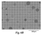
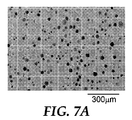
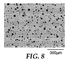
本開示は、熱硬化された成分と放射線硬化された成分とを有する研磨層を備えた多孔質研磨パッドと、そのような研磨パッドの製造方法と、を提供する。ポリマー粒子の使用により、研磨層中に孔が組み込まれる。本明細書に開示する多孔質研磨パッド中の孔は、概してより低い孔径不均一性と、従来の熱硬化された研磨パッドの孔よりも小さい孔径と、を有する独立気泡孔である。孔径及び孔の分布の制御は、例えば、研磨パッドの研磨性能において有利であり得る。 The present disclosure provides a porous polishing pad comprising a polishing layer having a thermally cured component and a radiation cured component, and a method for manufacturing such a polishing pad. Through the use of polymer particles, pores are incorporated into the polishing layer. The pores in the porous polishing pad disclosed herein are closed cell pores that generally have lower pore size non-uniformities and pore sizes that are smaller than those of conventional heat-cured polishing pads. Control of pore size and pore distribution can be advantageous, for example, in polishing performance of the polishing pad.
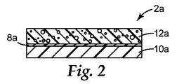
1つの態様において、本開示は研磨パッドを提供し、研磨パッドは、
対向する第1の面及び第2の面を有する柔軟層と、
柔軟層の第1の面上に配置された多孔質研磨層と、を備え、多孔質研磨層は、
熱硬化成分と放射性硬化成分とを含む架橋網状組織であって、放射性硬化成分と熱硬化成分とが架橋網状組織中で共有結合されている、架橋網状組織と、
架橋網状組織中に分散されたポリマー粒子と、
架橋網状組織中に分散された独立気泡孔と、を含む。いくつかの実施形態では、研磨パッドは、柔軟層と多孔質研磨層との間に介在する支持層を更に備える。
In one aspect, the present disclosure provides a polishing pad, the polishing pad comprising
A flexible layer having opposing first and second surfaces;
A porous polishing layer disposed on the first surface of the flexible layer, the porous polishing layer comprising:
A crosslinked network comprising a thermosetting component and a radiation curable component, wherein the radiation curable component and the thermosetting component are covalently bonded in the crosslinked network; and
Polymer particles dispersed in a crosslinked network;
Closed cell pores dispersed in the crosslinked network. In some embodiments, the polishing pad further comprises a support layer interposed between the flexible layer and the porous polishing layer.
別の態様では、本開示は、研磨パッドの製造方法を提供し、方法は、
熱硬化性樹脂組成物、放射線硬化性樹脂組成物、及びポリマー粒子を含む組成物を提供する工程と、
組成物中に孔を形成する工程と、
組成物を支持層上に配置する工程と、
組成物を放射線に暴露して、放射線硬化性樹脂組成物を少なくとも部分的に硬化させ、組成物を加熱して、熱硬化性樹脂組成物を少なくとも部分的に硬化させることにより、支持層上に多孔質研磨層を形成する工程と、を含む。いくつかの実施形態では、本方法は、多孔質研磨層の反対側の支持層表面に柔軟層を接着結合する工程を更に含む。
In another aspect, the present disclosure provides a method of manufacturing a polishing pad, the method comprising:
Providing a thermosetting resin composition, a radiation curable resin composition, and a composition comprising polymer particles;
Forming pores in the composition; and
Placing the composition on a support layer;
By exposing the composition to radiation to at least partially cure the radiation curable resin composition and heating the composition to at least partially cure the thermosetting resin composition on the support layer Forming a porous polishing layer. In some embodiments, the method further comprises adhesively bonding a flexible layer to the support layer surface opposite the porous polishing layer.
更なる態様において、本開示は研磨方法を提供し、方法は、
基材表面を、本開示による研磨パッドの多孔質研磨層と接触させる工程と、
研磨パッドを基材に対して相対的に移動して、基材の表面を擦り減らす工程と、を含む。
In a further aspect, the present disclosure provides a polishing method comprising:
Contacting the substrate surface with a porous polishing layer of a polishing pad according to the present disclosure;
Moving the polishing pad relative to the substrate to reduce the surface of the substrate.
本開示による研磨パッドの代表的な実施形態は、多様な研磨用途にそれらを使用することを可能にする多様な特徴及び特性を有する。いくつかの実施形態では、本開示の研磨パッドは、集積回路及び半導体デバイスの製造に使用されるウェハの化学機械的平坦化(CMP)に特に好適である場合がある。いくつかの実施形態では、本開示に記載される研磨パッドは、以下の利点のいくつか又は全てを提供し得る。 Exemplary embodiments of polishing pads according to the present disclosure have a variety of features and characteristics that allow them to be used in a variety of polishing applications. In some embodiments, the polishing pads of the present disclosure may be particularly suitable for chemical mechanical planarization (CMP) of wafers used in the manufacture of integrated circuits and semiconductor devices. In some embodiments, the polishing pad described in this disclosure may provide some or all of the following advantages.
例えば、いくつかの実施形態では、本開示による研磨パッドは、CMPプロセスで使用される加工液をパッドの研磨表面と基材の被研磨表面との間の境界面に保持することを改善するように作用することによって、増強研磨における加工液の効果を改善することができる。別の代表的な実施形態では、本開示による研磨パッドは、研磨中のウェハ表面のディッシング及び/又はエッジ侵食を低減又は除去することができる。いくつかの代表的な実施形態では、本開示による研磨パッドをCMPプロセスに使用することは、ウェハ内部の研磨均一性の向上、研磨後のウェハ表面の平坦性の向上、ウェハからのエッジダイ収率の向上、並びにCMPプロセス運転条件及び一貫性の向上をもたらすことができる。更なる実施形態では、本開示による研磨パッドの使用は、より大きい直径のウェハの加工を可能にする一方で、高いチップ収率を得るために必要な度合いの表面均一性を維持すること、又はウェハ表面の研磨均一性を維持するためにパッド表面のコンディショニングが必要になる前により多くのウェハを加工すること、又はパッドコンディショナのプロセス時間及び磨耗を減らすこと、を可能にすることができる。 For example, in some embodiments, a polishing pad according to the present disclosure improves retention of a working fluid used in a CMP process at the interface between the pad polishing surface and the substrate polished surface. By acting on, it is possible to improve the effect of the processing liquid in the enhanced polishing. In another exemplary embodiment, a polishing pad according to the present disclosure can reduce or eliminate dishing and / or edge erosion of the wafer surface during polishing. In some exemplary embodiments, using a polishing pad according to the present disclosure in a CMP process may improve polishing uniformity within the wafer, improve wafer surface flatness after polishing, edge die yield from the wafer. As well as improved CMP process operating conditions and consistency. In a further embodiment, the use of a polishing pad according to the present disclosure allows processing of larger diameter wafers while maintaining the degree of surface uniformity necessary to obtain a high chip yield, or It may be possible to process more wafers before pad surface conditioning is required to maintain polishing uniformity on the wafer surface, or to reduce the process time and wear of the pad conditioner.
本開示では、
「孔径の不均一性」とは、孔径の平均の標準偏差を平均孔径により除算し、100を乗算したものを指す。
In this disclosure,
“Pore diameter non-uniformity” refers to the average standard deviation of the pore diameters divided by the average pore diameter and multiplied by 100.
用語「ポリウレタン」は、2つ以上のウレタン結合(−NH−C(O)−O−)、尿素結合(−NH−C(O)−NH−又は−NH−C(O)−N(R)−、式中、Rは水素、脂肪族、環式脂肪族、又は芳香族基であってもよい)、ビウレット、アロファネート、ウレトジオン、又はイソシアヌレート結合を任意の組み合わせで有するポリマーを指す。 The term “polyurethane” refers to two or more urethane bonds (—NH—C (O) —O—), urea bonds (—NH—C (O) —NH— or —NH—C (O) —N (R )-, Where R may be hydrogen, aliphatic, cycloaliphatic, or aromatic groups), biuret, allophanate, uretdione, or a polymer having an isocyanurate bond in any combination.
用語「(メタ)アクリレート」は、アクリレート類及びメタクリレート類を指し、これらはウレタンアクリレート類、メタクリレート類、及びアクリレート類とメタクリレート類との組み合わせを含むことができる。 The term “(meth) acrylate” refers to acrylates and methacrylates, which can include urethane acrylates, methacrylates, and combinations of acrylates and methacrylates.
用語「高分子」は、低相対分子量の分子から誘導される複数の繰り返し単位を含む構造を有する分子を指す。用語「高分子」は、「オリゴマー」を含む。 The term “polymer” refers to a molecule having a structure comprising a plurality of repeating units derived from a molecule of low relative molecular weight. The term “polymer” includes “oligomers”.
「a」、「an」、及び「the」等の用語は、1つの実体のみを指すことを意図するものではなく、具体例を例示のために用いることができる一般分類を含む。用語「a」、「an」、及び「the」は、用語「少なくとも1つ」と同じ意味で使用される。 Terms such as “a”, “an”, and “the” are not intended to refer to only one entity, but include a general classification that can be used for illustration purposes. The terms “a”, “an”, and “the” are used interchangeably with the term “at least one”.
品目リストがその後に続くフレーズ「〜のうちの少なくとも1つ」及び「〜のうちの少なくとも1つを含む」は、リスト内の品目のいずれか1つ及びリスト内の2つ以上の品目の任意の組み合わせを指す。 The phrases “at least one of” and “comprising at least one of” are followed by any one of the items in the list and two or more items in the list. Refers to a combination of
全ての数値範囲は、特に明記しない限り、その端点と、端点間の非整数値を含む。 All numerical ranges include the endpoints and non-integer values between the endpoints unless otherwise specified.
本開示の代表的な実施形態の種々の態様及び利点の概要がまとめられてきた。前述の課題を解決するための手段は、本開示の例示されたそれぞれの実施形態又は全ての実施を記載するものではない。下記の図及び発明を実施するための形態では、本開示のいくつかの実施形態が更に詳細に例示されている。 A summary of various aspects and advantages of exemplary embodiments of the present disclosure has been compiled. The above summary is not intended to describe each illustrated embodiment or every implementation of the present disclosure. In the following figures and detailed description, several embodiments of the present disclosure are illustrated in more detail.
本開示の代表的な実施形態を添付の図面を参照して更に説明する。
図中、同じ参照番号は、同様の要素を指す。本明細書に含まれる図は、縮尺図ではなく、これらの図中、研磨パッドの構成要素は、選択された特徴を強調するために採られたサイズである。 In the figures, the same reference numbers refer to similar elements. The figures included herein are not to scale, in which the components of the polishing pad are sized to highlight selected features.
典型的なCMPパッドは、孔を有する熱硬化性(例えば、ポリウレタン)材料から構成されている。孔は、マイクロバルーン、可溶性繊維、ガス閉じ込め(例えば、インサイチュー又はエクスサイチュー生成)、及び物理的な空気閉じ込め等の多様な方法を用いて生成され得る。これらの方法を用いる際、重合中に発生する温度勾配、成形操作により生じるスキン/コア効果、繊維の分布、可溶性繊維の溶解速度、及び研磨化学(polishing chemistry)により、パッドのあらゆる所の孔径、孔の体積、及び分布を制御することは困難であり得る。 A typical CMP pad is constructed from a thermoset (eg, polyurethane) material with holes. The pores can be generated using a variety of methods such as microballoons, soluble fibers, gas confinement (eg, in situ or ex situ generation), and physical air confinement. When using these methods, the temperature gradient generated during the polymerization, the skin / core effect resulting from the molding operation, the fiber distribution, the dissolution rate of the soluble fiber, and the polishing chemistry, It can be difficult to control the volume and distribution of the pores.
いくつかの市販のCMPパッドは、イソシアネート樹脂の熱硬化中に生成した連続気泡パッド構造を有する。図1は、商業的に作製された、PPG Industries(Pittsburgh,PA)から商標名「S7」で入手可能な連続気泡CMPパッドの断面図及び上面図を示す。図1に示すように、このパッド中の孔径、孔の形状、及び分布は制御されていない。 Some commercially available CMP pads have an open cell pad structure generated during thermal curing of the isocyanate resin. FIG. 1 shows a cross-sectional and top view of an open-cell CMP pad commercially available from PPG Industries (Pittsburgh, Pa.) Available under the trade name “S7”. As shown in FIG. 1, the hole diameter, hole shape, and distribution in the pad are not controlled.
本開示は、一般に、制御された孔径及び均一性を有する独立気泡孔が形成されている、改良された多孔質研磨パッドに関する。ここで本開示の様々な代表的実施形態が記述される。本開示の代表的な実施形態は、開示の趣旨及び範囲から逸脱することなく、様々な修正や変更が可能である。したがって、本発明の実施形態は以下に記述する代表的な実施形態に限定されず、請求項及びそれと同等の任意のものに定められた制限によって支配されるものと理解されたい。 The present disclosure generally relates to an improved porous polishing pad in which closed cell pores with controlled pore size and uniformity are formed. Various representative embodiments of the present disclosure will now be described. Various modifications and changes can be made to the exemplary embodiments of the present disclosure without departing from the spirit and scope of the disclosure. Therefore, it should be understood that the embodiments of the present invention are not limited to the representative embodiments described below, but are governed by the limitations set forth in the claims and any equivalents thereto.
以下図2を参照すると、多孔質研磨パッド2aは、柔軟層10aと、柔軟層の片面(即ち、1つの主表面)上に配置された多孔質研磨層12aと、を備える。多孔質研磨層12aと柔軟層10aとの間には、本開示の多孔質研磨パッド及び方法のいくつかの実施形態に有用な、任意の支持層8aが介在している。多孔質研磨層は、架橋網状組織、架橋網状組織中に分散されたポリマー粒子、及び架橋網状組織中に分散された独立気泡孔を含む。研磨パッドの成分が研磨中に除去されて空隙を形成する(例えば、侵食又は溶解により)研磨パッド及び方法とは対照的に、本開示による研磨パッドは、研磨プロセスを開始するに先だって多孔質である。
Referring to FIG. 2 below, the
研磨層中の代表的なポリマー粒子としては、熱可塑性ポリマー粒子、熱硬化性ポリマー粒子、及びこれらの混合物を挙げることができる。用語「熱可塑性ポリマー」は、本質的に架橋されず、本質的に三次元網状組織を形成しない高分子材料を指す。用語「熱硬化性」は、少なくとも実質的に架橋されるポリマーを指し、ポリマーは本質的に三次元網状組織を有する。いくつかの実施形態では、ポリマー粒子は、加熱により粒子の最小限の焼結が存在する(即ち、本開示の研磨パッド中のポリマー粒子の境界面に最小限の塑性流動が存在し、ポリマー粒子の粒子間融合が殆どあるいは全く存在しない)ように選択されてもよい。いくつかの実施形態では、パッドのポリマー粒子が微粒子熱可塑性ポリマーを含む場合、研磨パッドは、微粒子熱可塑性ポリマーの融点又は焼結点未満で調製され得る。別の実施形態では、ポリマー粒子は熱硬化性ポリマーを含む。 Exemplary polymer particles in the polishing layer can include thermoplastic polymer particles, thermosetting polymer particles, and mixtures thereof. The term “thermoplastic polymer” refers to a polymeric material that is essentially not cross-linked and essentially does not form a three-dimensional network. The term “thermoset” refers to a polymer that is at least substantially cross-linked, the polymer having an essentially three-dimensional network. In some embodiments, the polymer particles have minimal sintering of the particles upon heating (ie, there is minimal plastic flow at the interface of the polymer particles in the polishing pad of the present disclosure, and the polymer particles May be selected such that there is little or no interparticle fusion. In some embodiments, if the pad polymer particles comprise a particulate thermoplastic polymer, the polishing pad can be prepared below the melting point or sintering point of the particulate thermoplastic polymer. In another embodiment, the polymer particles comprise a thermosetting polymer.
本開示の実施に有用なポリマー粒子は、様々な方法(例えば、縮合反応、フリーラジカル開始反応、又はこれらの組み合わせ)により調製され得る。更なる別の実施形態では、ポリマーは、段階的な又は同時の縮合及びフリーラジカル重合反応により形成された相互貫入(interpenetrating)ポリマー網状組織を含んでもよい。本開示において、用語「相互貫入ポリマー網状組織」(IPN)は、両方とも網状組織形態にある2種のポリマーの組み合わせを指し、少なくともその1つのポリマーは、直近に存在する他方のポリマー中で、合成又は架橋されている。典型的にはIPNにおいて、2つのポリマー間に、誘導された共有結合が存在しない。このように、機械的なブレンド及び共重合に加えて、IPNは、異なるポリマーが物理的に組み合わされ得る別のメカニズムを表している。 Polymer particles useful in the practice of the present disclosure can be prepared by a variety of methods, such as condensation reactions, free radical initiation reactions, or combinations thereof. In yet another embodiment, the polymer may comprise an interpenetrating polymer network formed by stepwise or simultaneous condensation and free radical polymerization reactions. In this disclosure, the term “interpenetrating polymer network” (IPN) refers to a combination of two polymers, both in network form, at least one of which is in the other existing polymer, It is synthesized or cross-linked. Typically in IPN, there is no induced covalent bond between the two polymers. Thus, in addition to mechanical blending and copolymerization, IPN represents another mechanism by which different polymers can be physically combined.
ポリマー粒子は、様々な方法により調製することができる。いくつかの実施形態では、バルクポリマーを低温粉砕し、所望の粒径範囲に分級してもよい。ポリマー粒子の形状は、規則的又は不規則であってもよく、以下の形状を含んでもよい。球、繊維、円板、フレーク、及びこれらの組み合わせ又は混合物。いくつかの実施形態では、ポリマー粒子は、実質的に球状である。用語「実質的に球状」は、少なくとも0.75(いくつかの実施形態では、少なくとも0.8、0.85、0.9、0.95、0.96、0.97、又は0.98)の球形度を有する物品を指す。いくつかの実施形態では、ポリマー粒子は繊維である。本開示の実施に有用な繊維は、典型的には少なくとも1.5:1、例えば、少なくとも2:1、3:1、4:1、5:1、10:1、25:1、50:1、75:1、100:1又はそれ以上の縦横比(即ち、最長寸法と最短寸法との比)を有する。本開示の実施に有用な繊維は、2:1〜100:1、5:1〜75:1、又は10:1〜50:1の範囲の縦横比を有してもよい。 The polymer particles can be prepared by various methods. In some embodiments, the bulk polymer may be cryomilled and classified to the desired particle size range. The shape of the polymer particles may be regular or irregular, and may include the following shapes. Spheres, fibers, disks, flakes, and combinations or mixtures thereof. In some embodiments, the polymer particles are substantially spherical. The term “substantially spherical” is at least 0.75 (in some embodiments, at least 0.8, 0.85, 0.9, 0.95, 0.96, 0.97, or 0.98). ). In some embodiments, the polymer particles are fibers. Fibers useful in the practice of this disclosure are typically at least 1.5: 1, such as at least 2: 1, 3: 1, 4: 1, 5: 1, 10: 1, 25: 1, 50 :. 1. Aspect ratio (ie, ratio of longest dimension to shortest dimension) of 1, 75: 1, 100: 1 or greater. Fibers useful in the practice of the present disclosure may have an aspect ratio in the range of 2: 1 to 100: 1, 5: 1 to 75: 1, or 10: 1 to 50: 1.
いくつかの実施形態では、ポリマー粒子は、少なくとも5(いくつかの実施形態では、少なくとも7、10、15、20、25、30、40、又は50)マイクロメートルの平均粒径を有してもよい。いくつかの実施形態では、ポリマー粒子は、最大500(いくつかの実施形態では、最大400、300、200、又は100)マイクロメートルの平均粒径を有してもよい。粒径は、一般に粒子の直径を指すが、粒子が球状ではない(例えば、繊維)実施形態では、粒子の最大寸法を指してもよい。ポリマー粒子の平均粒径は、従来の方法により測定することができる。例えば、ポリマー粒子の平均粒径は、Beckman Coulter Incorporatedにより製造及び市販されているCoulter LS粒径分析器等の光散乱技術を用いて測定することができる。本明細書及び特許請求の範囲で使用される「粒径」は、Coulter Counter LS粒径分析器を使用した光散乱により測定される体積パーセントに基づいた粒子の直径又は最大寸法を指す。この光散乱技術では、粒径は、粒子の実際の形状にかかわらず、流体回転半径(hydrodynamic radius of gyration)から測定される。「平均」粒径は、体積パーセントに基づいた粒子の平均直径である。いくつかの実施形態、特に粒子が繊維である実施形態では、繊維は、従来のふるい分け技術で測定して、最大約600、500、又は450マイクロメートル(30、35、又は40 U.S.Mesh)の最大粒径を有する。例えば、いくつかの実施形態では、少なくとも97、98、又は99パーセントの繊維は、600、500、又は400マイクロメートル(30、35、又は40 U.S.Mesh)の開口部を有するふるいを通過する。 In some embodiments, the polymer particles may have an average particle size of at least 5 (in some embodiments, at least 7, 10, 15, 20, 25, 30, 40, or 50) micrometers. Good. In some embodiments, the polymer particles may have an average particle size of up to 500 (in some embodiments, up to 400, 300, 200, or 100) micrometers. Particle size generally refers to the diameter of the particle, but in embodiments where the particle is not spherical (eg, a fiber), it may refer to the largest dimension of the particle. The average particle diameter of the polymer particles can be measured by a conventional method. For example, the average particle size of the polymer particles can be measured using light scattering techniques such as a Coulter LS particle size analyzer manufactured and marketed by Beckman Coulter Incorporated. “Particle size” as used herein and in the claims refers to the diameter or maximum dimension of a particle based on volume percent measured by light scattering using a Coulter Counter LS particle size analyzer. In this light scattering technique, the particle size is measured from the hydrodynamic radius of gyration, regardless of the actual shape of the particle. The “average” particle size is the average diameter of the particles based on volume percent. In some embodiments, particularly those in which the particles are fibers, the fibers may be up to about 600, 500, or 450 micrometers (30, 35, or 40 US Mesh) as measured by conventional sieving techniques. ) Maximum particle size. For example, in some embodiments, at least 97, 98, or 99 percent of the fiber passes through a sieve having an opening of 600, 500, or 400 micrometers (30, 35, or 40 US Mesh). To do.
いくつかの実施形態では、ポリマー粒子は、高い度合いの均一性を有する。いくつかの実施形態では、ポリマー粒子の粒径の不均一性は、最大75(いくつかの実施形態では、最大70、65、60、65、又は50)パーセントである。粒径の不均一性とは、粒径の標準偏差を平均粒径で除算し、100を乗算したものを指す。 In some embodiments, the polymer particles have a high degree of uniformity. In some embodiments, the non-uniformity in the particle size of the polymer particles is up to 75 (in some embodiments, up to 70, 65, 60, 65, or 50) percent. Particle size non-uniformity refers to the standard deviation of particle size divided by the average particle size multiplied by 100.
いくつかの実施形態では、ポリマー粒子は、実質的に中実である。本明細書で使用される用語「実質的に中実」は、微粒子ポリマーが中空ではなく、例えば、ポリマー粒子が中空マイクロカプセルの形態ではないことを意味する。しかしながら、いくつかの実施形態では、実質的に中実のポリマー粒子は、閉じ込められた気泡を含む場合がある。 In some embodiments, the polymer particles are substantially solid. The term “substantially solid” as used herein means that the particulate polymer is not hollow, for example, the polymer particles are not in the form of hollow microcapsules. However, in some embodiments, the substantially solid polymer particles may contain trapped bubbles.
好適なポリマー粒子としては、ポリ塩化ビニル、ポリフッ化ビニル、ポリエチレン、ポリプロピレン、ナイロン、ポリカーボネート、ポリエステル、ポリ(メタ)アクリレート、ポリエーテル、ポリアミド、ポリウレタン、ポリエポキシド、ポリスチレン、ポリイミド(例えば、ポリエーテルイミド)、ポリスルホン及びこれらの混合物が挙げられる。いくつかの実施形態では、ポリマー粒子は、ポリ(メタ)アクリレート、ポリウレタン、ポリエポキシド及びこれらの混合物から選択されてもよい。 Suitable polymer particles include polyvinyl chloride, polyvinyl fluoride, polyethylene, polypropylene, nylon, polycarbonate, polyester, poly (meth) acrylate, polyether, polyamide, polyurethane, polyepoxide, polystyrene, polyimide (eg, polyetherimide). , Polysulfones and mixtures thereof. In some embodiments, the polymer particles may be selected from poly (meth) acrylates, polyurethanes, polyepoxides, and mixtures thereof.
いくつかの実施形態では、ポリマー粒子は水溶性粒子を含む。代表的な有用な水溶性粒子としては、糖類(例えば、デキストリン、シクロデキストリン、澱粉、マンニトール、及び乳糖等の多糖類)、セルロース類(例えば、ヒドロキシプロピルセルロース類及びメチルセルロース類)、タンパク質、ポリビニルアルコール、ポリビニルピロリドン、ポリアクリル酸、ポリエチレンオキシド、水溶性感光性樹脂、スルホン化ポリイソプレン、スルホン化ポリイソプレンコポリマー、及びこれらの任意の組み合わせから作製される粒子が挙げられる。いくつかの実施形態では、ポリマー粒子はセルロースを含む。これらの実施形態のいくつかでは、ポリマー粒子はメチルセルロースを含む。これらの実施形態では、ポリマー粒子は水溶性粒子を含むが、ポリマー粒子は研磨層が形成される際に研磨層中に孔を形成することができる。研磨中に粒子を溶解できる加工液は、孔の形成に必要ではない。 In some embodiments, the polymer particles include water soluble particles. Typical useful water-soluble particles include sugars (eg, polysaccharides such as dextrin, cyclodextrin, starch, mannitol, and lactose), celluloses (eg, hydroxypropylcelluloses and methylcelluloses), proteins, polyvinyl alcohol. , Polyvinyl pyrrolidone, polyacrylic acid, polyethylene oxide, water-soluble photosensitive resin, sulfonated polyisoprene, sulfonated polyisoprene copolymer, and any combination thereof. In some embodiments, the polymer particles comprise cellulose. In some of these embodiments, the polymer particles comprise methylcellulose. In these embodiments, the polymer particles comprise water-soluble particles, but the polymer particles can form pores in the polishing layer when the polishing layer is formed. A working fluid capable of dissolving the particles during polishing is not necessary for the formation of the holes.
いくつかの実施形態では、ポリマー粒子はポリウレタンを含み、ポリウレタンは、例えば、少なくとも2つのイソシアネート基、及び/又は少なくとも2つの末端保護されたイソシアネート基を有する末端保護イソシアネート反応物を含む樹脂と;イソシアネート基と反応性の少なくとも2つの基を有する第2の樹脂と、から調製されてもよい。 In some embodiments, the polymer particles comprise a polyurethane, the polyurethane comprising, for example, a resin comprising an end-protected isocyanate reactant having at least two isocyanate groups and / or at least two end-protected isocyanate groups; And a second resin having at least two groups reactive with the group.
いくつかの実施形態では、第1及び第2の樹脂を一緒に混合し、重合又は硬化させてバルクポリウレタンを形成してもよく、ポリウレタンを次いで粉砕(例えば、低温粉砕)し、場合により分級してもよい。いくつかの実施形態では、ポリマー粒子は、第1及び第2の樹脂を一緒に混合し、この混合物を撹拌下で、加熱された脱イオン水中にゆっくり注ぎ(場合により有機共溶媒及び/又は界面活性剤の存在下で)、形成された微粒子材料を単離し(例えば、濾過により)、単離された微粒子材料を乾燥し、乾燥された微粒子ポリウレタンを場合により分級することにより形成されてもよい。別の実施形態では、イソシアネート及び水素材料を、有機溶媒(例えば、アルコール類、水不溶性エーテル類、分枝状及び直鎖状炭化水素類、ケトン類、トルエン、キシレン及びこれらの混合物)の存在下で一緒に混合してもよい。 In some embodiments, the first and second resins may be mixed together and polymerized or cured to form a bulk polyurethane, which may then be ground (eg, cold ground) and optionally classified. May be. In some embodiments, the polymer particles mix the first and second resins together and slowly pour the mixture under stirring into heated deionized water (optionally organic co-solvent and / or interface). May be formed by isolating the formed particulate material (in the presence of an activator) (eg, by filtration), drying the isolated particulate material, and optionally classifying the dried particulate polyurethane. . In another embodiment, the isocyanate and hydrogen materials are present in the presence of an organic solvent (eg, alcohols, water-insoluble ethers, branched and straight chain hydrocarbons, ketones, toluene, xylene, and mixtures thereof). May be mixed together.
いくつかの実施形態では、少なくとも2つのイソシアネート基を含む第1の樹脂は、イソシアネート官能性モノマー類、イソシアネート官能性プレポリマー類及びこれらの組み合わせから選択されてもよい。代表的な好適なイソシアネートモノマー類としては、脂肪族ポリイソシアネート類;エチレン的に不飽和なポリイソシアネート類;脂環式ポリイソシアネート類;イソシアネート基が芳香族環に直接結合されていない芳香族ポリイソシアネート類、例えばα,α’−キシレンジイソシアネート;イソシアネート基が芳香族環に直接結合された芳香族ポリイソシアネート類、例えばベンゼンジイソシアネート;これらポリイソシアネート類のハロゲン化、アルキル化、アルコキシル化、ニトロ化、カルボジイミド変性、尿素変性、及びビウレット変性誘導体類;並びにこれらポリイソシアネート類の二量体化及び三量体化生成物が挙げられる。 In some embodiments, the first resin comprising at least two isocyanate groups may be selected from isocyanate functional monomers, isocyanate functional prepolymers, and combinations thereof. Typical suitable isocyanate monomers include: aliphatic polyisocyanates; ethylenically unsaturated polyisocyanates; alicyclic polyisocyanates; aromatic polyisocyanates in which the isocyanate group is not directly bonded to an aromatic ring Such as α, α′-xylene diisocyanate; aromatic polyisocyanates in which the isocyanate group is directly bonded to an aromatic ring, such as benzene diisocyanate; halogenation, alkylation, alkoxylation, nitration, carbodiimide of these polyisocyanates Modified, urea-modified, and biuret-modified derivatives; and dimerization and trimerization products of these polyisocyanates.
代表的な脂肪族ポリイソシアネート類としては、エチレンジイソシアネート、トリメチレンジイソシアネート、テトラメチレンジイソシアネート、ヘキサメチレンジイソシアネート、オクタメチレンジイソシアネート、ノナメチレンジイソシアネート、2,2’−ジメチルペンタンジイソシアネート、2,2,4−トリメチルヘキサンジイソシアネート、デカメチレンジイソシアネート、2,4,4,−トリメチルヘキサメチレンジイソシアネート、1,6,1−ウンデカントリイソシアネート、1,3,6−ヘキサメチレントリイソシアネート、1,8−ジイソシアナト−4−(イソシアナトメチル)オクタン、2,5,7−トリメチル−1,8−ジイソシアナト−5−(イソシアナトメチル)オクタン、ビス(イソシアナトエチル)−カーボネート、ビス(イソシアナトエチル)エーテル、2−イソシアナトプロピル−2,6−ジイソシアナトヘキサノエート、リシンジイソシアネートメチルエステル、リシントリイソシアネートメチルエステル及びこれらの混合物が挙げられる。 Typical aliphatic polyisocyanates include ethylene diisocyanate, trimethylene diisocyanate, tetramethylene diisocyanate, hexamethylene diisocyanate, octamethylene diisocyanate, nonamethylene diisocyanate, 2,2′-dimethylpentane diisocyanate, 2,2,4-trimethyl. Hexane diisocyanate, decamethylene diisocyanate, 2,4,4, -trimethylhexamethylene diisocyanate, 1,6,1-undecane triisocyanate, 1,3,6-hexamethylene triisocyanate, 1,8-diisocyanato-4- (isocyanate Natomethyl) octane, 2,5,7-trimethyl-1,8-diisocyanato-5- (isocyanatomethyl) octane, bis (isocyanatoethyl) -ca Boneto, bis (isocyanatoethyl) ether, 2-isocyanatopropyl-2,6-diisocyanato hexanoate, lysine diisocyanate methyl ester, ricin triisocyanate methyl ester and mixtures thereof.
代表的な好適なエチレン的に不飽和なポリイソシアネート類としては、ブテンジイソシアネート及び1,3−ブタジエン−1,4−ジイソシアネートを挙げることができる。代表的な好適な脂環式ポリイソシアネート類としては、イソホロンジイソシアネート、シクロヘキサンジイソシアネート、メチルシクロヘキサンジイソシアネート、ビス(イソシアナトメチル)シクロヘキサン、ビス(イソシアナトシクロヘキシル)メタン、ビス(イソシアナトシクロヘキシル)−2,2−プロパン、ビス(イソシアナトシクロヘキシル)−1,2−エタン、2−イソシアナトメチル−3−(3−イソシアナトプロピル)−5−イソシアナトメチル−ビシクロ[2.2.1]−ヘプタン、2−イソシアナトメチル−3−(3−イソシアナトプロピル)−6−イソシアナトメチル−ビシクロ[2.2.1]−ヘプタン、2−イソシアナトメチル−2−(3−イソシアナトプロピル)−5−イソシアナトメチル−ビシクロ[2.2.1]−ヘプタン、2−イソシアナトメチル−2−(3−イソシアナトプロピル)−6−イソシアナトメチル−ビシクロ[2.2.1]−ヘプタン、2−イソシアナトメチル−3−(3−イソシアナトプロピル)−6−(2−イソシアナトエチル)−ビシクロ[2.2.1]−ヘプタン、2−イソシアナトメチル−2−(3−イソシアナトプロピル)−5−(2−イソシアナトエチル)−ビシクロ[2.2.1]−ヘプタン、2−イソシアナトメチル−2−(3−イソシアナトプロピル)−6−(2−イソシアナトエチル)−ビシクロ[2.2.1]−ヘプタン及びこれらの混合物が挙げられる。 Representative suitable ethylenically unsaturated polyisocyanates include butene diisocyanate and 1,3-butadiene-1,4-diisocyanate. Typical suitable alicyclic polyisocyanates include isophorone diisocyanate, cyclohexane diisocyanate, methylcyclohexane diisocyanate, bis (isocyanatomethyl) cyclohexane, bis (isocyanatocyclohexyl) methane, bis (isocyanatocyclohexyl) -2,2 -Propane, bis (isocyanatocyclohexyl) -1,2-ethane, 2-isocyanatomethyl-3- (3-isocyanatopropyl) -5-isocyanatomethyl-bicyclo [2.2.1] -heptane, 2 -Isocyanatomethyl-3- (3-isocyanatopropyl) -6-isocyanatomethyl-bicyclo [2.2.1] -heptane, 2-isocyanatomethyl-2- (3-isocyanatopropyl) -5 Isocyanatomethyl-bicyclo [2. .1] -heptane, 2-isocyanatomethyl-2- (3-isocyanatopropyl) -6-isocyanatomethyl-bicyclo [2.2.1] -heptane, 2-isocyanatomethyl-3- (3- Isocyanatopropyl) -6- (2-isocyanatoethyl) -bicyclo [2.2.1] -heptane, 2-isocyanatomethyl-2- (3-isocyanatopropyl) -5- (2-isocyanatoethyl) ) -Bicyclo [2.2.1] -heptane, 2-isocyanatomethyl-2- (3-isocyanatopropyl) -6- (2-isocyanatoethyl) -bicyclo [2.2.1] -heptane and These mixtures are mentioned.
イソシアネート基が芳香族環に直接結合されていない、代表的な芳香族ポリイソシアネート類としては、ビス(イソシアナトエチル)ベンゼン、α,α,α’,α’−テトラメチルキシレンジイソシアネート、1,3−ビス(1−イソシアナト−1−メチルエチル)ベンゼン、ビス(イソシアナトブチル)ベンゼン、ビス(イソシアナトメチル)ナフタレン、ビス(イソシアナトメチル)ジフェニルエーテル、ビス(イソシアナトエチル)フタレート、メシチレントリイソシアネート、2,5−ジ(イソシアナトメチル)フラン及びこれらの混合物が挙げられる。 Typical aromatic polyisocyanates in which the isocyanate group is not directly bonded to the aromatic ring include bis (isocyanatoethyl) benzene, α, α, α ′, α′-tetramethylxylene diisocyanate, 1,3 -Bis (1-isocyanato-1-methylethyl) benzene, bis (isocyanatobutyl) benzene, bis (isocyanatomethyl) naphthalene, bis (isocyanatomethyl) diphenyl ether, bis (isocyanatoethyl) phthalate, mesitylene triisocyanate, 2,5-di (isocyanatomethyl) furan and mixtures thereof.
芳香族環に直接結合したイソシアネート基を有する代表的な好適な芳香族ポリイソシアネート類としては、フェニレンジイソシアネート、エチルフェニレンジイソシアネート、イソプロピルフェニレンジイソシアネート、ジメチルフェニレンジイソシアネート、ジエチルフェニレンジイソシアネート、ジイソプロピルフェニレンジイソシアネート、トリメチルベンゼントリイソシアネート、ベンゼントリイソシアネート、ナフタレンジイソシアネート、メチルナフタレンジイソシアネート、ビフェニルジイソシアネート、オルト−トリジンジイソシアネート、4,4’−ジフェニルメタンジイソシアネート、ビス(3−メチル−4−イソシアナトフェニル)メタン、ビス(イソシアナトフェニル)エチレン、3,3’−ジメトキシ−ビフェニル−4,4’−ジイソシアネート、トリフェニルメタントリイソシアネート、高分子4,4’−ジフェニルメタンジイソシアネート、ナフタレントリイソシアネート、ジフェニルメタン−2,4,4’−トリイソシアネート、4−メチルジフェニルメタン−3,5,2’,4’,6’−ペンタイソシアネート、ジフェニルエーテルジイソシアネート、ビス(イソシアナトフェニルエーテル)エチレングリコール、ビス(イソシアナトフェニルエーテル)−1,3−プロピレングリコール、ベンゾフェノンジイソシアネート、カルバゾールジイソシアネート、エチルカルバゾールジイソシアネート、ジクロロカルバゾールジイソシアネート及びこれらの混合物が挙げられる。 Representative suitable aromatic polyisocyanates having an isocyanate group directly bonded to an aromatic ring include phenylene diisocyanate, ethylphenylene diisocyanate, isopropylphenylene diisocyanate, dimethylphenylene diisocyanate, diethylphenylene diisocyanate, diisopropylphenylene diisocyanate, trimethylbenzene tris. Isocyanate, benzene triisocyanate, naphthalene diisocyanate, methyl naphthalene diisocyanate, biphenyl diisocyanate, ortho-tolidine diisocyanate, 4,4'-diphenylmethane diisocyanate, bis (3-methyl-4-isocyanatophenyl) methane, bis (isocyanatophenyl) ethylene 3,3′-dimethoxy-biphenyl -4,4'-diisocyanate, triphenylmethane triisocyanate, polymer 4,4'-diphenylmethane diisocyanate, naphthalene triisocyanate, diphenylmethane-2,4,4'-triisocyanate, 4-methyldiphenylmethane-3,5,2 ', 4', 6'-pentaisocyanate, diphenyl ether diisocyanate, bis (isocyanatophenyl ether) ethylene glycol, bis (isocyanatophenyl ether) -1,3-propylene glycol, benzophenone diisocyanate, carbazole diisocyanate, ethylcarbazole diisocyanate, dichloro Examples include carbazole diisocyanate and mixtures thereof.
いくつかの実施形態では、少なくとも2つのイソシアネート基を含む第1の樹脂は、α,α’−キシレンジイソシアネート、α,α,α’,α’−テトラメチルキシレンジイソシアネート、イソホロンジイソシアネート、ビス(イソシアナトシクロヘキシル)メタン、トルエンジイソシアネート、4,4’−ジフェニルメタンジイソシアネート、及びこれらの混合物からなる群から選択される。 In some embodiments, the first resin comprising at least two isocyanate groups is α, α′-xylene diisocyanate, α, α, α ′, α′-tetramethylxylene diisocyanate, isophorone diisocyanate, bis (isocyanato). (Cyclohexyl) methane, toluene diisocyanate, 4,4′-diphenylmethane diisocyanate, and mixtures thereof.
いくつかの実施形態では、少なくとも2つのイソシアネート基を有する第1の樹脂は、イソシアネート官能性ポリウレタンプレポリマーを含んでもよい。イソシアネート官能性ポリウレタンプレポリマー類は、従来の様々な技術により調製することができる。いくつかの実施形態では、ジオール等の少なくとも1つのポリオールと、ジイソシアネートモノマー等の少なくとも1つのイソシアネート官能性モノマーとを互いに反応させて、少なくとも2つのイソシアネート基を有するポリウレタンプレポリマーを形成してもよい。代表的な好適なイソシアネート官能性モノマー類としては、前述したイソシアネート官能性モノマー類が挙げられる。 In some embodiments, the first resin having at least two isocyanate groups may comprise an isocyanate functional polyurethane prepolymer. Isocyanate functional polyurethane prepolymers can be prepared by a variety of conventional techniques. In some embodiments, at least one polyol, such as a diol, and at least one isocyanate functional monomer, such as a diisocyanate monomer, can be reacted with each other to form a polyurethane prepolymer having at least two isocyanate groups. . Representative suitable isocyanate functional monomers include the isocyanate functional monomers described above.
本開示の実施に有用な好適なイソシアネート官能性ポリウレタンプレポリマー類は、広い範囲内の様々な分子量を有してもよい。いくつかの実施形態では、イソシアネート官能性ポリウレタンプレポリマーは、ポリスチレン基準を使用したゲル透過クロマトグラフィー(GPC)により測定して、500〜15,000、又は500〜5000の数平均分子量(Mn)を有してもよい。 Suitable isocyanate functional polyurethane prepolymers useful in the practice of the present disclosure may have various molecular weights within a wide range. In some embodiments, the isocyanate functional polyurethane prepolymer has a number average molecular weight (Mn) of 500-15,000, or 500-5000, as measured by gel permeation chromatography (GPC) using polystyrene standards. You may have.
イソシアネート官能性ポリウレタンプレポリマー類の調製に有用な代表的なポリオール類としては、1,2−エタンジオール、1,3−プロパンジオール、1,2−プロパンジオール、1,4−ブタンジオール、1,3−ブタンジオール、グリセロール、ネオペンチルグリコール、トリメチロールエタン、トリメチロールプロパン、ジ−トリメチロールプロパン、エリスリトール、ペンタエリスリトール及びジ−ペンタエリスリトール等の直鎖又は分枝鎖アルカンポリオール類;ジ−、トリ−及びテトラエチレングリコール、並びにジ−、トリ−及びテトラプロピレングリコール等のポリアルキレングリコール類;シクロペンタンジオール、シクロヘキサンジオール、シクロヘキサントリオール、シクロヘキサンジメタノール、ヒドロキシプロピルシクロヘキサノール及びシクロヘキサンジエタノール等の環状アルカンポリオール類;ジヒドロキシベンゼン、ベンゼントリオール、ヒドロキシベンジルアルコール及びジヒドロキシトルエン等の芳香族ポリオール類;4,4’−イソプロピリデンジフェノール(ビスフェノールA)、4,4’−オキシビスフェノール、4,4’−ジヒドロキシベンゾフェノン、4,4’−チオビスフェノール、フェノールフタレイン、ビス(4−ヒドロキシフェニル)メタン(ビスフェノールF)、4,4’−(1,2−エテンジイル)ビスフェノール及び4,4’−スルホニルビスフェノール等のビスフェノール類;4,4’−イソプロピリデンビス(2,6−ジブロモフェノール)、4,4’−イソプロピリデンビス(2,6−ジクロロフェノール)及び4,4’−イソプロピリデンビス(2,3,5,6−テトラクロロフェノール)等のハロゲン化ビスフェノール類;エトキシ、プロポキシ、α−ブトキシ及びβ−ブトキシ基等の1つ以上のアルコキシ基を有するアルコキシル化4,4’−イソプロピリデンジフェノール等のアルコキシル化ビスフェノール類;並びに4,4’−イソプロピリデン−ビスシクロヘキサノール、4,4’−オキシビスシクロヘキサノール、4,4’−チオビスシクロヘキサノール及びビス(4−ヒドロキシシクロヘキサノール)メタン等の、対応するビスフェノールを水素化することにより調製できるビスシクロヘキサノール類が挙げられる。 Representative polyols useful for the preparation of isocyanate functional polyurethane prepolymers include 1,2-ethanediol, 1,3-propanediol, 1,2-propanediol, 1,4-butanediol, 1, Linear or branched alkane polyols such as 3-butanediol, glycerol, neopentyl glycol, trimethylolethane, trimethylolpropane, di-trimethylolpropane, erythritol, pentaerythritol and di-pentaerythritol; -And tetraethylene glycol, and polyalkylene glycols such as di-, tri- and tetrapropylene glycol; cyclopentanediol, cyclohexanediol, cyclohexanetriol, cyclohexanedimethanol, hydroxypropyl Cyclic alkane polyols such as pyrcyclohexanol and cyclohexanediethanol; aromatic polyols such as dihydroxybenzene, benzenetriol, hydroxybenzyl alcohol and dihydroxytoluene; 4,4′-isopropylidenediphenol (bisphenol A), 4,4 ′ -Oxybisphenol, 4,4'-dihydroxybenzophenone, 4,4'-thiobisphenol, phenolphthalein, bis (4-hydroxyphenyl) methane (bisphenol F), 4,4 '-(1,2-ethenediyl) bisphenol And bisphenols such as 4,4′-sulfonylbisphenol; 4,4′-isopropylidenebis (2,6-dibromophenol), 4,4′-isopropylidenebis (2,6-dichloropheno) And halogenated bisphenols such as 4,4′-isopropylidenebis (2,3,5,6-tetrachlorophenol); one or more alkoxy such as ethoxy, propoxy, α-butoxy and β-butoxy groups Alkoxylated bisphenols such as alkoxylated 4,4'-isopropylidenediphenol having a group; and 4,4'-isopropylidene-biscyclohexanol, 4,4'-oxybiscyclohexanol, 4,4'-thio Biscyclohexanols that can be prepared by hydrogenating the corresponding bisphenols, such as biscyclohexanol and bis (4-hydroxycyclohexanol) methane.
イソシアネート官能性ポリウレタンプレポリマー類の調製に有用な好適なポリオール類の更なる例としては、200〜2000グラム/モルの数平均分子量(Mn)を有するポリエチレングリコール等のより高次のポリアルキレングリコール類;メチルメタクリレートとヒドロキシエチルメタクリレートのコポリマー類等の、(メタ)アクリレート類とヒドロキシ官能性(メタ)アクリレート類の共重合により形成されたもの等のヒドロキシル−支持アクリル樹脂;並びにブタンジオール等のジオール類と、アジピン酸又はアジピン酸ジエチル等の二酸類又はジエステル類との反応により形成されたもの等のヒドロキシ官能性ポリエステル類が挙げられる。いくつかの実施形態では、本開示の実施に有用なポリオールは、200〜2000グラム/モルの数平均分子量(Mn)を有してもよい。 Further examples of suitable polyols useful for the preparation of isocyanate functional polyurethane prepolymers include higher order polyalkylene glycols such as polyethylene glycol having a number average molecular weight (Mn) of 200 to 2000 grams / mole. Hydroxyl-supported acrylic resins such as those formed by copolymerization of (meth) acrylates and hydroxy-functional (meth) acrylates, such as copolymers of methyl methacrylate and hydroxyethyl methacrylate; and diols such as butanediol And hydroxy-functional polyesters such as those formed by reaction of diacids such as adipic acid or diethyl adipate or diesters. In some embodiments, polyols useful in the practice of the present disclosure may have a number average molecular weight (Mn) of 200 to 2000 grams / mole.
いくつかの実施形態では、イソシアネート官能性ポリウレタンプレポリマーは、トルエンジイソシアネート等のジイソシアネートを、ポリ(テトラヒドロフラン)等のポリアルキレングリコールと反応させることにより調製されてもよい。 In some embodiments, an isocyanate functional polyurethane prepolymer may be prepared by reacting a diisocyanate such as toluene diisocyanate with a polyalkylene glycol such as poly (tetrahydrofuran).
いくつかの実施形態では、イソシアネート官能性ポリウレタンプレポリマーは、触媒の存在下で調製されてもよい。いくつかの実施形態では、使用される触媒の量は、ポリオール及びイソシアネート官能性モノマーの総重量に基づいて、5重量パーセント未満、又は3重量パーセント未満、又は1重量パーセント未満であってもよい。いくつかの実施形態では、代表的な好適な触媒として、オクサン酸スズ、ジブチルスズジラウレート、ジブチルスズジアセテート、ジブチルスズメルカプチド、ジブチルスズジマレエート、ジメチルスズジアセテート、ジメチルスズジラウレート等の有機酸のスズ付加物、1,4−ジアザビシクロ[2.2.2]オクタン、及びこれらの混合物が挙げられる。別の実施形態では、触媒は、オクサン酸亜鉛、ビスマス、又は第二鉄アセチルアセトネートであってもよい。更なる代表的な好適な触媒としては、トリエチルアミン、トリイソプロピルアミン及びN,N−ジメチルベンジルアミン等の第三級アミン類が挙げられる。 In some embodiments, the isocyanate functional polyurethane prepolymer may be prepared in the presence of a catalyst. In some embodiments, the amount of catalyst used may be less than 5 weight percent, or less than 3 weight percent, or less than 1 weight percent, based on the total weight of polyol and isocyanate functional monomer. In some embodiments, representative suitable catalysts include tin addition of organic acids such as tin oxalate, dibutyltin dilaurate, dibutyltin diacetate, dibutyltin mercaptide, dibutyltin dimaleate, dimethyltin diacetate, dimethyltin dilaurate, etc. , 1,4-diazabicyclo [2.2.2] octane, and mixtures thereof. In another embodiment, the catalyst may be zinc oxalate, bismuth, or ferric acetylacetonate. Further representative suitable catalysts include tertiary amines such as triethylamine, triisopropylamine and N, N-dimethylbenzylamine.
ポリマー粒子の作製に有用なポリウレタンの実施形態では、少なくとも2つのイソシアネート基を有する第1の樹脂としては、少なくとも2つの末端保護イソシアネート基を有する末端保護イソシアネート化合物が挙げられる。用語「末端保護イソシアネート化合物」は、脱末端保護(即ち、遊離)イソシアネート基及び別個の又は遊離末端保護基に転換されてもよい末端及び/又は懸垂末端保護イソシアネート基を有するモノマー又はプレポリマーを指す。好適なイソシアネート化合物の前述した例のいずれも、末端保護されることができる。イソシアネートの代表的な非一時的な(nonfugitive)末端保護基としては、1H−イミダゾール、1H−ピラゾール、3,5−ジメチル−1H−ピラゾール、1H−1,2,3−トリアゾール、1H−1,2,3−ベンゾトリアゾール、1H−1,2,4−トリアゾール、1H−5−メチル−1,2,4−トリアゾール及び1H−3−アミノ−1,2,4−トリアゾール等の1H−アゾール類;e−カプロラクタム及び2−ピロリジノン等のラクタム類;3−アミノプロピルモルホリン等のモルホリン類;並びにN−ヒドロキシフタルイミドが挙げられる。末端保護イソシアネート化合物の代表的な一時的な(fugitive)末端保護基としては、プロパノール、イソプロパノール、ブタノール、イソブタノール、tert−ブタノール及びヘキサノール等のアルコール類;エチレングリコールモノアルキルエーテル類(例えば、エチレングリコールモノブチルエーテル及びエチレングリコールモノヘキシルエーテル)及びプロピレングリコールモノアルキルエーテル類(例えば、プロピレングリコールモノメチルエーテル)等のアルキレングリコールモノアルキルエーテル類;並びにメチルエチルケトオキシム等のケトオキシム類が挙げられる。 In polyurethane embodiments useful for making polymer particles, the first resin having at least two isocyanate groups includes a terminal protected isocyanate compound having at least two terminal protected isocyanate groups. The term “terminally protected isocyanate compound” refers to a monomer or prepolymer having a terminally protected (ie, free) isocyanate group and a terminal and / or pendant terminally protected isocyanate group that may be converted to a separate or free terminal protecting group. . Any of the aforementioned examples of suitable isocyanate compounds can be end-protected. Representative nonfugitive terminal protecting groups for isocyanate include 1H-imidazole, 1H-pyrazole, 3,5-dimethyl-1H-pyrazole, 1H-1,2,3-triazole, 1H-1, 1H-azoles such as 2,3-benzotriazole, 1H-1,2,4-triazole, 1H-5-methyl-1,2,4-triazole and 1H-3-amino-1,2,4-triazole Lactams such as e-caprolactam and 2-pyrrolidinone; morpholines such as 3-aminopropylmorpholine; and N-hydroxyphthalimide. Typical fugitive terminal protecting groups for terminally protected isocyanate compounds include alcohols such as propanol, isopropanol, butanol, isobutanol, tert-butanol and hexanol; ethylene glycol monoalkyl ethers (eg, ethylene glycol) Monobutyl ethers and ethylene glycol monohexyl ethers) and alkylene glycol monoalkyl ethers such as propylene glycol monoalkyl ethers (for example, propylene glycol monomethyl ether); and ketoximes such as methyl ethyl ketoxime.
任意の理論に束縛されるものではないが、少なくとも2つのイソシアネート基を有する末端保護イソシアネート材料を第1の樹脂中に含ませることにより、(a)微粒子ポリウレタン粒子の少なくとも一部分の間;及び/又は(b)微粒子ポリウレタンの少なくとも一部分と架橋網状組織の少なくとも一部分との間に共有結合の形成がもたらされ得ると考えられる。いくつかの実施形態では、末端保護イソシアネート化合物は、第1の樹脂の末端保護イソシアネート基が、遊離イソシアネート及び末端保護イソシアネート基の総モル当量に基づいて、少なくとも5モルパーセント、又は少なくとも10モルパーセント、又は40モルパーセント未満、又は50モルパーセント未満の量で存在するように存在してもよい。 Without being bound by any theory, by including in the first resin an end-protected isocyanate material having at least two isocyanate groups, (a) between at least a portion of the particulate polyurethane particles; and / or (B) It is believed that a covalent bond can be formed between at least a portion of the particulate polyurethane and at least a portion of the crosslinked network. In some embodiments, the end-protected isocyanate compound is such that the end-protected isocyanate group of the first resin is at least 5 mole percent, or at least 10 mole percent, based on the total molar equivalents of free isocyanate and end-protected isocyanate groups. Or it may be present to be present in an amount of less than 40 mole percent, or less than 50 mole percent.
イソシアネート基と反応性の少なくとも2つの基を有する第2の樹脂は、非常に様々な材料から選択されることができる。いくつかの実施形態では、第2の樹脂は、ヒドロキシル、メルカプト、第1級アミン、第2級アミン及びこれらの組み合わせから選択される官能基を有する。代表的な好適な第2の樹脂としては、前述したポリオール類が挙げられる。 The second resin having at least two groups reactive with isocyanate groups can be selected from a wide variety of materials. In some embodiments, the second resin has a functional group selected from hydroxyl, mercapto, primary amine, secondary amine, and combinations thereof. Exemplary suitable second resins include the aforementioned polyols.
いくつかの実施形態では、イソシアネート基と反応性の少なくとも2つの基を有し得る第2の樹脂としては、ポリアミンが挙げられる。代表的なポリアミン類としては、エチレンジアミン(EDA)、ジエチレントリアミン(DETA)、トリエチレンテトラミン(TETA)、テトラエチレンペンタミン(TEPA)、ペンタエチレンヘキサミン(PEHA)、ピペラジン、ジエチレンジアミン(DEDA)、及び2−アミノ−1−エチルピペラジン等のエチレンアミン類が挙げられる。更なる代表的な好適なポリアミン類としては、3,5−ジメチル−2,4−トルエンジアミン、3,5−ジメチル−2,6−トルエンジアミン、3,5−ジエチル−2,4−トルエンジアミン、3,5−ジエチル−2,6−トルエンジアミン、3,5−ジイソプロピル−2,4−トルエンジアミン、3,5−ジイソプロピル−2,6−トルエンジアミン及びこれらの混合物等の、ジアルキルトルエンジアミンの1つ以上の異性体が挙げられる。いくつかの実施形態では、ポリアミンは、メチレンジアニリン、トリメチレングリコールジ(パラ−アミノベンゾエート)、並びにアミン末端オリゴマー類及びプレポリマー類から選択されてもよい。 In some embodiments, the second resin that may have at least two groups reactive with isocyanate groups includes polyamines. Typical polyamines include ethylenediamine (EDA), diethylenetriamine (DETA), triethylenetetramine (TETA), tetraethylenepentamine (TEPA), pentaethylenehexamine (PEHA), piperazine, diethylenediamine (DEDA), and 2 -Ethyleneamines such as amino-1-ethylpiperazine. Further representative suitable polyamines include 3,5-dimethyl-2,4-toluenediamine, 3,5-dimethyl-2,6-toluenediamine, 3,5-diethyl-2,4-toluenediamine. , 3,5-diethyl-2,6-toluenediamine, 3,5-diisopropyl-2,4-toluenediamine, 3,5-diisopropyl-2,6-toluenediamine, and mixtures thereof. One or more isomers may be mentioned. In some embodiments, the polyamine may be selected from methylene dianiline, trimethylene glycol di (para-aminobenzoate), and amine-terminated oligomers and prepolymers.
いくつかの実施形態では、好適なポリアミン類は、4,4’−メチレン−ビス(ジアルキルアニリン)に基づくもの(例えば、4,4’−メチレン−ビス(2,6−ジメチルアニリン)、4,4’−メチレン−ビス(2,6−ジエチルアニリン)、4,4’−メチレン−ビス(2−エチル−6−メチルアニリン)、4,4’−メチレン−ビス(2,6−ジイソプロピルアニリン)、4,4’−メチレン−ビス(2−イソプロピル−6−メチルアニリン)、4,4’−メチレン−ビス(2,6−ジエチル−3−クロロアニリン)及びこれらの混合物から選択されてもよい。 In some embodiments, suitable polyamines are based on 4,4′-methylene-bis (dialkylaniline) (eg, 4,4′-methylene-bis (2,6-dimethylaniline), 4'-methylene-bis (2,6-diethylaniline), 4,4'-methylene-bis (2-ethyl-6-methylaniline), 4,4'-methylene-bis (2,6-diisopropylaniline) 4,4′-methylene-bis (2-isopropyl-6-methylaniline), 4,4′-methylene-bis (2,6-diethyl-3-chloroaniline), and mixtures thereof. .
いくつかの実施形態では、少なくとも2つのイソシアネート基を含む第1の樹脂と、イソシアネートと反応性の少なくとも2つの基を含む第2の樹脂と、からの微粒子ポリウレタンの調製は、触媒の存在下で行われてもよい。好適な触媒としては、イソシアネート官能性ポリウレタンプレポリマーの調製において上記に列挙したものが挙げられる。 In some embodiments, the preparation of the particulate polyurethane from a first resin comprising at least two isocyanate groups and a second resin comprising at least two groups reactive with isocyanate is carried out in the presence of a catalyst. It may be done. Suitable catalysts include those listed above in the preparation of the isocyanate functional polyurethane prepolymer.
いくつかの実施形態では、微粒子ポリウレタンの調製に有用な、イソシアネート基及び任意の末端保護イソシアネート基とイソシアネート反応性基とのモル当量比は、0.5:1.0〜1.5:1.0、例えば0.7:1.0〜1.3:1.0又は0.8:1.0〜1.2:1.0である。いくつかの実施形態では、架橋ポリウレタンは、ウレタン又は尿素結合が残りのイソシアネートと反応するように、化学量論的に必要な量未満の第2の樹脂を使用することにより調製されてもよい。別の実施形態では、二官能性化合物を三官能性化合物により部分的に置き換えることにより、熱的により安定な化学的架橋がもたらされるであろう。 In some embodiments, the molar equivalent ratio of isocyanate groups and optional end-protected isocyanate groups to isocyanate-reactive groups useful for the preparation of particulate polyurethanes is 0.5: 1.0 to 1.5: 1. 0, for example 0.7: 1.0 to 1.3: 1.0 or 0.8: 1.0 to 1.2: 1.0. In some embodiments, the crosslinked polyurethane may be prepared by using less than the stoichiometrically required amount of the second resin so that the urethane or urea linkages react with the remaining isocyanate. In another embodiment, partial replacement of a bifunctional compound with a trifunctional compound will result in a more thermally stable chemical crosslink.
いくつかの有用な微粒子ポリウレタンは市販されており、例えばDainichiseika Color & Chemicals Mfg.Co.,Ltd.Advanced Polymers Group(Tokyo,Japan)から商標名「DAIMIC−BEAZ」にて等級「UCN−5350D」、「UCN−5150D」、及び「UCN−5070D」で市販されており、またNegami Chemical Industrial Co.,Ltd.(Nomi−city,Japan)から商標名「ART PEARL」で入手可能なポリウレタン粒子;及び例えば、Bayer Corporationから商標名「TEXIN」で入手可能な脂肪族ポリエーテルベースの熱可塑性ポリウレタンがある。 Some useful microparticulate polyurethanes are commercially available, see, for example, Dainichiseika Color & Chemicals Mfg. Co. , Ltd., Ltd. Commercially available from Advanced Polymers Group (Tokyo, Japan) under the trade names “DAIMIC-BEAZ” under the grades “UCN-5350D”, “UCN-5150D”, and “UCN-5070D”, and also from Negami Chemical Ind. , Ltd., Ltd. Polyurethane particles available under the trade name “ART PEARL” from (Nomi-city, Japan); and, for example, aliphatic polyether-based thermoplastic polyurethanes available under the trade name “TEXIN” from Bayer Corporation.
いくつかの実施形態では、本開示の実施に有用な好適なポリマー粒子としては、微粒子ポリエポキシド類が挙げられる。微粒子ポリエポキシドは、例えば、少なくとも2つのエポキシド基を有する第1の樹脂と、エポキシドのエポキシド基と反応性の少なくとも2つの基を有する第2の樹脂と、の反応生成物から調製されてもよい。 In some embodiments, suitable polymer particles useful in the practice of the present disclosure include particulate polyepoxides. The particulate polyepoxide may be prepared, for example, from the reaction product of a first resin having at least two epoxide groups and a second resin having at least two groups reactive with the epoxide groups of the epoxide.
いくつかの実施形態では、少なくとも2つのエポキシド基を含む第1の樹脂と第2の樹脂とを一緒に混合し、重合又は硬化させてバルクポリエポキシドを形成し、これを次いで粉砕(例えば、低温粉砕)し、場合により分級してもよい。いくつかの実施形態では、微粒子ポリエポキシドは、エポキシド官能性材料と水素官能性材料とを一緒に混合し、この混合物を撹拌下で、加熱された脱イオン水中にゆっくり注ぎ、形成された微粒子材料を単離し(例えば、濾過により)、単離された微粒子材料を乾燥し、乾燥された微粒子ポリエポキシドを場合により分級することにより形成されてもよい。 In some embodiments, a first resin containing at least two epoxide groups and a second resin are mixed together and polymerized or cured to form a bulk polyepoxide, which is then ground (eg, cold milled). ) And may be classified according to circumstances. In some embodiments, the particulate polyepoxide mixes the epoxide functional material and the hydrogen functional material together and slowly pours the mixture into heated deionized water under agitation to remove the particulate material formed. It may be formed by isolation (eg, by filtration), drying the isolated particulate material, and optionally classifying the dried particulate polyepoxide.
いくつかの実施形態では、本開示の実施に有用な好適なエポキシド官能性材料としては、エポキシド官能性モノマー類、エポキシド官能性プレポリマー類及びこれらの組み合わせが挙げられる。代表的な好適なエポキシド官能性モノマー類としては、1,2,3,4−ジエポキシブタン、1,2,7,8−ジエポキシオクタン等の脂肪族ポリエポキシド類;1,2,4,5−ジエポキシシクロヘキサン、1,2,5,6−ジエポキシシクロオクタン、7−オキサ−ビシクロ[4.1.0]ヘプタン−3−カルボン酸7−オキサ−ビシクロ[4.1.0]ヘプタ−3−イルメチルエステル、1,2−エポキシ−4−オキシラニル−シクロヘキサン及び2,3−(エポキシプロピル)シクロヘキサン等の環式脂肪族ポリエポキシド類;ビス(4−ヒドロキシフェニル)メタンジグリシジルエーテル等の芳香族ポリエポキシド類;水素化ビスフェノールAジエポキシド並びにこれらの混合物を挙げることができる。本開示に有用であり得るエポキシド官能性モノマー類は、典型的には、ポリオールとエピハロヒドリン、例えばエピクロロヒドリンとの反応により調製される。エポキシド官能性モノマー類の調製に使用され得るポリオール類としては、イソシアネート官能性プレポリマーの調製に関連して本明細書で以前引用されたものが挙げられる。エポキシド官能性モノマー類の有用なクラスとしては、ビスフェノールとエピクロロヒドリンとの反応により調製されたものが挙げられる(例えば、4,4’−イソプロピリデンジフェノールとエピクロロヒドリンとを反応させて4,4’−イソプロピリデンジフェノールジグリシジルエーテルを形成する)。 In some embodiments, suitable epoxide functional materials useful in the practice of the present disclosure include epoxide functional monomers, epoxide functional prepolymers, and combinations thereof. Representative suitable epoxide functional monomers include aliphatic polyepoxides such as 1,2,3,4-diepoxybutane, 1,2,7,8-diepoxyoctane; 1,2,4,5 -Diepoxycyclohexane, 1,2,5,6-diepoxycyclooctane, 7-oxa-bicyclo [4.1.0] heptane-3-carboxylic acid 7-oxa-bicyclo [4.1.0] hepta Cycloaliphatic polyepoxides such as 3-ylmethyl ester, 1,2-epoxy-4-oxiranyl-cyclohexane and 2,3- (epoxypropyl) cyclohexane; Fragrance such as bis (4-hydroxyphenyl) methane diglycidyl ether Mention may be made of the group polyepoxides; hydrogenated bisphenol A diepoxides and mixtures thereof. Epoxide functional monomers that may be useful in the present disclosure are typically prepared by reaction of a polyol with an epihalohydrin, such as epichlorohydrin. Polyols that can be used in the preparation of epoxide functional monomers include those previously cited herein in connection with the preparation of isocyanate functional prepolymers. A useful class of epoxide functional monomers includes those prepared by reaction of bisphenol with epichlorohydrin (eg, reacting 4,4′-isopropylidenediphenol with epichlorohydrin. 4,4′-isopropylidenediphenol diglycidyl ether).
いくつかの実施形態では、特定のエポキシド類の調製に有用なエポキシド官能性プレポリマーは、高分子ポリオールとエピクロロヒドリンとを反応させることにより調製されてもよい。代表的な好適な高分子ポリオール類としては、ポリエチレングリコール及びポリテトラヒドロフラン等のポリアルキレングリコール類;ポリエステルポリオール類;ポリウレタンポリオール類;ポリ((メタ)アクリレート)ポリオール類;並びにこれらの混合物を挙げることができる。 In some embodiments, epoxide functional prepolymers useful for the preparation of certain epoxides may be prepared by reacting a polymeric polyol with epichlorohydrin. Representative suitable polymeric polyols include polyalkylene glycols such as polyethylene glycol and polytetrahydrofuran; polyester polyols; polyurethane polyols; poly ((meth) acrylate) polyols; and mixtures thereof. it can.
本開示のいくつかの実施形態では、エポキシド官能性プレポリマーは、(メタ)アクリレートモノマーと、ラジカル重合性のエポキシド官能性モノマー(例えば、グリシジル(メタ)アクリレート)と、から調製され得るエポキシ官能性ポリ((メタ)アクリレート)ポリマーを含んでもよい。好適なエポキシド官能性プレポリマー類は、広い範囲の分子量を有することができる。いくつかの実施形態では、エポキシド官能性プレポリマーの分子量は、例えば、ポリスチレン基準を使用したゲル透過クロマトグラフィー(GPC)により測定して、500〜15,000グラム/モル、又は500〜5000グラム/モルであってもよい。 In some embodiments of the present disclosure, the epoxide functional prepolymer can be prepared from a (meth) acrylate monomer and a radical polymerizable epoxide functional monomer (eg, glycidyl (meth) acrylate). Poly ((meth) acrylate) polymers may be included. Suitable epoxide functional prepolymers can have a wide range of molecular weights. In some embodiments, the molecular weight of the epoxide functional prepolymer is determined, for example, by 500-15,000 grams / mole, or 500-5000 grams / mole, as measured by gel permeation chromatography (GPC) using polystyrene standards. Mole may be sufficient.
エポキシド類と反応性の少なくとも2つの基を有する第2の樹脂は、ヒドロキシル、メルカプト、カルボン酸、第1級アミン、又は第2級アミンのうちの少なくとも1つを含んでもよい。いくつかの実施形態では、第2の樹脂は、本明細書で以前引用されたポリオール類を含んでもよい。別の実施形態では、第2の樹脂は、本明細書で以前引用されたポリアミン類を含んでもよい。いくつかの実施形態では、好適なポリアミン類は、第1級アミン類、第2級アミン類、及びこれらの組み合わせから選択される少なくとも2つのアミン基を有するポリアミドプレポリマー類を含んでもよい。好適な代表的なポリアミドプレポリマー類としては、例えば、Cognis Corporation,Coating & Inks Division(Monheim,Germany)から商標名「VERSAMID」で入手可能なものを挙げることができる。 The second resin having at least two groups reactive with epoxides may comprise at least one of hydroxyl, mercapto, carboxylic acid, primary amine, or secondary amine. In some embodiments, the second resin may include polyols previously cited herein. In another embodiment, the second resin may include polyamines previously cited herein. In some embodiments, suitable polyamines may include polyamide prepolymers having at least two amine groups selected from primary amines, secondary amines, and combinations thereof. Suitable representative polyamide prepolymers include, for example, those available from Cognis Corporation, Coating & Inks Division (Monheim, Germany) under the trade name “VERSAMID”.
いくつかの実施形態では、少なくとも2つのエポキシド基を含む第1の樹脂と、エポキシドと反応性の少なくとも2つの基を含む第2の樹脂と、からの微粒子エポキシドの調製は、触媒の存在下で行われてもよい。代表的な好適な触媒としては、トリエチルアミン、トリイソプロピルアミン、トリ第3級ブチルアミン、テトラフルオロホウ酸及びN,N−ジメチルベンジルアミン等の第3級アミンが挙げられる。いくつかの実施形態では、触媒は、第2の樹脂がエポキシド官能性材料と組み合わされる前に、第2の樹脂中に組み込まれてもよい。いくつかの実施形態では、使用される触媒の量は、組み合わされる第1及び第2の樹脂の総重量に基づいて、5重量パーセント未満、又は3重量パーセント未満、又は1重量パーセント未満であってもよい。 In some embodiments, the preparation of the particulate epoxide from a first resin comprising at least two epoxide groups and a second resin comprising at least two groups reactive with the epoxide is carried out in the presence of a catalyst. It may be done. Representative suitable catalysts include tertiary amines such as triethylamine, triisopropylamine, tri-tert-butylamine, tetrafluoroboric acid and N, N-dimethylbenzylamine. In some embodiments, the catalyst may be incorporated into the second resin before the second resin is combined with the epoxide functional material. In some embodiments, the amount of catalyst used is less than 5 weight percent, or less than 3 weight percent, or less than 1 weight percent, based on the combined weight of the first and second resins combined. Also good.
微粒子架橋ポリエポキシドの調製に使用される反応物の、エポキシド基とエポキシド反応性基とのモル当量比は、典型的には0.5:1.0〜2.0:1.0、例えば0.7:1.0〜1.3:1.0又は0.8:1.0〜1.2:1.0である。 The molar equivalent ratio of epoxide groups to epoxide reactive groups of the reactants used in the preparation of the microparticulate cross-linked polyepoxide is typically 0.5: 1.0 to 2.0: 1.0, for example 0.8. 7: 1.0-1.3: 1.0 or 0.8: 1.0-1.2: 1.0.
いくつかの実施形態では、少なくとも2つのイソシアネート基又は少なくとも2つのエポキシド基を有する第1の樹脂、及び/又は第2の樹脂は、場合により、既知の従来の添加剤を含んでもよい。そのような添加剤の例としては、熱安定剤、抗酸化剤、金型剥離剤、固定染料(static dyes)、顔料、アルコキシル化フェノールベンゾエート類及びポリ(アルキレングリコール)ジベンゾエート類等の柔軟化添加剤、並びにエチレンオキシド/プロピレンオキシドブロックコポリマー界面活性剤等の界面活性剤が挙げられる。いくつかの実施形態では、そのような添加剤は、組み合わされる第1及び第2の樹脂の総重量に基づいて、合計最大10重量パーセント、又は最大5重量パーセント、又は最大3重量パーセントの量で存在してもよい。 In some embodiments, the first resin having at least two isocyanate groups or at least two epoxide groups, and / or the second resin may optionally include known conventional additives. Examples of such additives include softening agents such as heat stabilizers, antioxidants, mold release agents, static dyes, pigments, alkoxylated phenol benzoates and poly (alkylene glycol) dibenzoates. Examples include additives and surfactants such as ethylene oxide / propylene oxide block copolymer surfactants. In some embodiments, such additives are in a total amount of up to 10 weight percent, or up to 5 weight percent, or up to 3 weight percent, based on the combined weight of the first and second resins combined. May be present.
本開示の実施に有用な他のポリマー粒子としては、例えばROHM America,Incorporated(Lawrenceville,Georgia)から商標名「ROHADON」で、またNegami Chemical Industrial Co.,Ltd.から商標名「ART PEARL」で市販されている熱可塑性ポリ(メタ)アクリレート類が挙げられる。本開示の実施に有用な更なる他のポリマー粒子としては、例えばDow Chemical Company(Midland,Michigan)から商標名「METHOCEL」で市販されているセルロース粒子が挙げられる。 Other polymer particles useful in the practice of the present disclosure include, for example, the trade name “RODADON” from ROHM America, Incorporated (Lawrenceville, Georgia) and also from Negami Chemical Industrial Co., Ltd. , Ltd., Ltd. Thermoplastic poly (meth) acrylates commercially available under the trade name "ART PEARL". Still other polymer particles useful in the practice of the present disclosure include, for example, cellulose particles commercially available from Dow Chemical Company (Midland, Michigan) under the trade name “METHOCEL”.
本開示による研磨パッド中に存在するポリマー粒子の量は、様々であってもよい。興味深いことに、いくつかの実施形態では、所定の技術を用いて混合されたポリマー粒子の量は、得られた研磨層の多孔率に予想外の形で影響することが見出された。例えば、旋回と回転を組み合わせたミキサーを使用する際、最大20重量パーセントの粒子レベルは、最大15重量パーセントの粒子レベルよりも少ない孔を提供することが見出された。しかしながら、他の混合技術は異なる結果を提供する可能性がある。いくつかの実施形態では、ポリマー粒子は、微粒子ポリマー及び架橋網状組織の総重量に基づいて、少なくとも1重量パーセント、又は少なくとも2.5重量パーセント、又は少なくとも5重量パーセントの量で存在する。いくつかの実施形態では、ポリマー粒子は、ポリマー粒子及び架橋網状組織の総重量に基づいて、最大25重量パーセント、又は最大20重量パーセント、又は20重量パーセント未満の量で存在してもよい。 The amount of polymer particles present in the polishing pad according to the present disclosure may vary. Interestingly, in some embodiments, the amount of polymer particles mixed using a given technique has been found to unexpectedly affect the porosity of the resulting abrasive layer. For example, when using a mixer that combines swirling and rotation, it has been found that a particle level of up to 20 weight percent provides fewer pores than a particle level of up to 15 weight percent. However, other mixing techniques can provide different results. In some embodiments, the polymer particles are present in an amount of at least 1 weight percent, or at least 2.5 weight percent, or at least 5 weight percent, based on the total weight of the particulate polymer and the crosslinked network. In some embodiments, the polymer particles may be present in an amount up to 25 weight percent, or up to 20 weight percent, or less than 20 weight percent, based on the total weight of the polymer particles and the crosslinked network.
ポリマー粒子が繊維である実施形態を含むいくつかの実施形態では、ポリマー粒子は、ポリマー粒子及び架橋網状組織の総重量に基づいて、最大10重量パーセント、又は最大5重量パーセント、又は5重量パーセント未満の量で存在してもよい。有利には、繊維形態のポリマー粒子は、ポリマー粒子及び架橋網状組織の総重量に基づいて、最大2重量パーセントのレベルにおいてでさえも、有用なレベルの多孔率を提供することができる。これらの実施形態のいくつかでは、ポリマー粒子は水溶性繊維(例えば、メチルセルロース繊維)である。実施例の表1及び2に示すように、メチルセルロース繊維を用いた場合、等重量の球状ポリウレタン粒子を用いた場合と比較して、より高いレベルの多孔率が得られる。実施例12の硬化組成物の断面図の顕微鏡写真である図8と、それぞれが実施例15の硬化組成物の断面図及び上面図の顕微鏡写真である図7A及び7Bとの目視比較により、2重量パーセントの繊維(図8)によって10重量パーセントの粒子(図7A及び7B)とほぼ同一の多孔率レベルが獲得できることが示される。 In some embodiments, including embodiments where the polymer particles are fibers, the polymer particles are up to 10 weight percent, or up to 5 weight percent, or less than 5 weight percent, based on the total weight of the polymer particles and the crosslinked network May be present in an amount of. Advantageously, the polymer particles in fiber form can provide useful levels of porosity, even at levels up to 2 weight percent, based on the total weight of the polymer particles and the crosslinked network. In some of these embodiments, the polymer particles are water soluble fibers (eg, methylcellulose fibers). As shown in Tables 1 and 2 of the Examples, when the methylcellulose fiber is used, a higher level of porosity can be obtained as compared with the case where equal weight spherical polyurethane particles are used. By visual comparison between FIG. 8 which is a micrograph of a cross-sectional view of the cured composition of Example 12, and FIGS. 7A and 7B which are micrographs of the cross-sectional view and top view of the cured composition of Example 15, respectively, 2 It is shown that a weight percent fiber (FIG. 8) can achieve a porosity level approximately the same as 10 weight percent particles (FIGS. 7A and 7B).
より低いレベルの粒子を組み込んで同一の多孔率を得ることは、例えば、架橋網状組織全体にわたる粒子分布の均一性を改善し、また研磨中にパッド表面の硬度を維持するのに有用であり得る。 Incorporating lower levels of particles to obtain the same porosity can be useful, for example, to improve the uniformity of particle distribution across the cross-linked network and to maintain the hardness of the pad surface during polishing. .
本開示による研磨パッドは、ポリマー粒子と、熱硬化成分及び放射性硬化成分を含む架橋網状組織と、を含む研磨層を備える。非常に様々な好適なポリマー類が、架橋網状組織の形成に有用であり得る。いくつかの実施形態では、熱硬化成分は、ポリウレタン、ポリエポキシド、又はウレタン変性ポリエポキシドのうちの少なくとも1つを含む。 A polishing pad according to the present disclosure comprises a polishing layer comprising polymer particles and a crosslinked network comprising a thermosetting component and a radiation curable component. A wide variety of suitable polymers can be useful in forming a crosslinked network. In some embodiments, the thermosetting component comprises at least one of polyurethane, polyepoxide, or urethane-modified polyepoxide.
典型的には、本開示の架橋網状組織は、ポリマー粒子の存在下で形成される。いくつかの実施形態では、硬化性樹脂組成物がポリマー粒子の間に存在する間に、熱硬化性樹脂組成物と放射線硬化性樹脂組成物とが反応して、架橋網状組織を形成し得る。 Typically, the crosslinked network of the present disclosure is formed in the presence of polymer particles. In some embodiments, the thermosetting resin composition and the radiation curable resin composition can react to form a crosslinked network while the curable resin composition is present between the polymer particles.
いくつかの実施形態では、本明細書に開示した研磨層は、ポリマー粒子及び架橋網状組織の総重量に基づいて、少なくとも75重量パーセント、又は少なくとも80重量パーセント、又は少なくとも85重量パーセントの架橋網状組織を含んでもよい。いくつかの実施形態では、架橋網状組織は、ポリマー粒子及び架橋網状組織の総重量に基づいて、最大99重量パーセント、又は最大95重量パーセント、又は最大90重量パーセントの量で、研磨層中に存在してもよい。 In some embodiments, the abrasive layer disclosed herein comprises at least 75 weight percent, or at least 80 weight percent, or at least 85 weight percent crosslinked network, based on the total weight of the polymer particles and crosslinked network. May be included. In some embodiments, the crosslinked network is present in the polishing layer in an amount of up to 99 weight percent, or up to 95 weight percent, or up to 90 weight percent, based on the total weight of the polymer particles and the crosslinked network. May be.
架橋網状組織は、従来の重合技術の方法により調製されてもよい。いくつかの実施形態では、架橋網状組織は、縮合反応、フリーラジカル開始反応、又はこれらの組み合わせにより形成されてもよい。いくつかの実施形態では、熱硬化成分は、ポリウレタンプレポリマーを含有する熱硬化性樹脂組成物をポリアミンと縮合させることにより形成されたポリウレタンを含んでもよい。いくつかの実施形態では、放射性硬化成分は、光開始剤の存在下でのウレタン−ジアクリレート又はウレタン−ジメタクリレートの重合により形成されたウレタン−ポリアクリレート又はウレタン−ポリメタクリレートを含んでもよい。いくつかの実施形態では、架橋網状組織は、段階的な又は同時の、熱硬化及び放射線硬化重合により形成された相互貫入ポリマー網状組織である。いくつかの実施形態では、放射性硬化成分(いくつかの実施形態ではポリアクリレート又はポリメタクリレート)は、例えばウレタン又は尿素結合基を介して、熱硬化成分に共有結合されている。 The crosslinked network may be prepared by methods of conventional polymerization techniques. In some embodiments, the crosslinked network may be formed by a condensation reaction, a free radical initiation reaction, or a combination thereof. In some embodiments, the thermosetting component may comprise a polyurethane formed by condensing a thermosetting resin composition containing a polyurethane prepolymer with a polyamine. In some embodiments, the radiation curable component may comprise a urethane-polyacrylate or urethane-polymethacrylate formed by polymerization of urethane-diacrylate or urethane-dimethacrylate in the presence of a photoinitiator. In some embodiments, the crosslinked network is an interpenetrating polymer network formed by stepwise or simultaneous thermosetting and radiation curable polymerization. In some embodiments, the radiation curable component (polyacrylate or polymethacrylate in some embodiments) is covalently bonded to the heat curable component, for example, via a urethane or urea linking group.
本開示の実施に有用な好適な熱硬化性樹脂組成物は、モノマー類、プレポリマー類、及びこれらの混合物を含有してもよい。いくつかの実施形態では、熱硬化性樹脂組成物は、触媒、架橋剤、硬化剤、溶媒、及び当該技術分野にて既知の他の従来の添加剤を含有してもよい。 Suitable thermosetting resin compositions useful in the practice of the present disclosure may contain monomers, prepolymers, and mixtures thereof. In some embodiments, the thermosetting resin composition may contain a catalyst, a crosslinking agent, a curing agent, a solvent, and other conventional additives known in the art.
いくつかの実施形態では、熱硬化性樹脂組成物は、末端保護イソシアネート基であってもよい少なくとも2つのイソシアネート基、又は少なくとも2つのエポキシド基を有する第1の樹脂と、イソシアネート類及び/又はエポキシド類と反応性の少なくとも2つの基(例えば、ヒドロキシル、アミノ、カルボキシ、又はメルカプタン基)を有する第2の樹脂と、を含有する。 In some embodiments, the thermosetting resin composition comprises a first resin having at least two isocyanate groups, which may be terminal protected isocyanate groups, or at least two epoxide groups, and isocyanates and / or epoxides. A second resin having at least two groups reactive with the class (eg, hydroxyl, amino, carboxy, or mercaptan groups).
熱硬化成分の調製に使用され得る代表的な好適な第1の樹脂及び第2の樹脂は、それぞれ微粒子ポリウレタン類に関して本明細書で以前記載されたイソシアネート類(プレポリマー類を含む)、末端保護イソシアネート類、ポリオール類及びポリアミン類から選択されてもよい。末端保護イソシアネート類の使用により、例えば、第1の樹脂及び第2の樹脂が組み合わされた際にゲル化の開始が遅延する可能性があり、このことは第1の樹脂及び第2の樹脂とポリマー粒子とを混合する、より長い時間を可能とし得る。 Representative suitable first and second resins that can be used in the preparation of the thermosetting component are the isocyanates (including prepolymers), end protections previously described herein for particulate polyurethanes, respectively. It may be selected from isocyanates, polyols and polyamines. The use of terminally protected isocyanates can delay the onset of gelation when, for example, the first resin and the second resin are combined, which is different from the first resin and the second resin. Longer times of mixing with the polymer particles may be possible.
第1の樹脂として有用ないくつかのイソシアネートプレポリマー類は市販されており、例えば、Air Products and Chemicals,Inc.(Allentown,PA)から商標名「AIRTHANE PHP−75D」で入手可能なイソシアネートプレポリマーがある。第2の樹脂として有用ないくつかのジアミン類が市販されており、例えばAir Products and Chemicals,Inc.から商標名「VERSALINK P250」及び「VERSALINK P650」で入手可能なオリゴマージアミンがある。 Some isocyanate prepolymers useful as the first resin are commercially available, see, eg, Air Products and Chemicals, Inc. There is an isocyanate prepolymer available from (Allentown, Pa.) Under the trade name “AIRTHANE PHP-75D”. Some diamines useful as the second resin are commercially available, see, eg, Air Products and Chemicals, Inc. There are oligomeric diamines available under the trade names "VERSALINK P250" and "VERSALINK P650".
いくつかの実施形態では、少なくとも2つのイソシアネート基を有する第1の樹脂と、イソシアネート基と反応性の少なくとも2つの基を有する第2の樹脂と、を含む、放射線硬化性樹脂及び熱硬化性樹脂を含有する組成物は、触媒を更に含んでもよい。代表的な好適な触媒としては、微粒子ポリウレタンの調製に関連して本明細書で以前引用されたもの(例えば、トリエチルアミン等の第3級アミン、及びジブチルスズジラウレート等の有機金属化合物)を挙げることができる。いくつかの実施形態では、触媒は、第1の樹脂と第2の樹脂とを組み合わせる前に、第2の樹脂中に組み込まれてもよい。いくつかの実施形態では、触媒は、組み合わされる第1及び第2の樹脂の総重量に基づいて、5重量パーセント未満、又は3重量パーセント未満、又は1重量パーセント未満の量で存在してもよい。第1の樹脂及び第2の樹脂中のイソシアネート基及び任意の末端保護イソシアネート基とイソシアネート反応性基とのモル当量比は、ぞれぞれ、0.5:1.0〜2.0:1.0、又は0.7:1.0〜1.3:1.0、又は0.8:1.0〜1.2:1.0であってもよい。 In some embodiments, radiation curable resins and thermosetting resins comprising: a first resin having at least two isocyanate groups; and a second resin having at least two groups reactive with isocyanate groups. The composition containing may further comprise a catalyst. Representative suitable catalysts include those previously cited herein in connection with the preparation of particulate polyurethanes (eg, tertiary amines such as triethylamine, and organometallic compounds such as dibutyltin dilaurate). it can. In some embodiments, the catalyst may be incorporated into the second resin before combining the first resin and the second resin. In some embodiments, the catalyst may be present in an amount less than 5 weight percent, or less than 3 weight percent, or less than 1 weight percent, based on the combined weight of the first and second resins combined. . The molar equivalent ratios of the isocyanate groups in the first resin and the second resin and any terminally protected isocyanate groups and isocyanate-reactive groups are 0.5: 1.0 to 2.0: 1, respectively. 0.0, or 0.7: 1.0 to 1.3: 1.0, or 0.8: 1.0 to 1.2: 1.0.
いくつかの実施形態では、熱硬化成分は、少なくとも2つのエポキシド基を有する第1の樹脂と;エポキシド基と反応性の少なくとも2つの基(例えば、ヒドロキシル、アミノ、カルボキシ、又はメルカプタン基)を有する第2の樹脂と、を反応させることにより調製されてもよい。少なくとも2つのエポキシド基を有する代表的な好適な第1の樹脂及び第2の樹脂としては、本明細書で以前説明した微粒子ポリエポキシドの調製に使用されるエポキシド類、ポリアミン類、及びポリオール類のいずれかが挙げられる。 In some embodiments, the thermosetting component has a first resin having at least two epoxide groups; and at least two groups reactive with the epoxide groups (eg, hydroxyl, amino, carboxy, or mercaptan groups) It may be prepared by reacting with a second resin. Exemplary suitable first and second resins having at least two epoxide groups include any of the epoxides, polyamines, and polyols used in the preparation of the particulate polyepoxide previously described herein. Can be mentioned.
いくつかの実施形態では、ポリエポキシドの熱的に硬化された成分の調製に使用される第1の樹脂及び第2の樹脂を含む、放射線硬化性樹脂及び熱硬化性樹脂を含有する組成物は、エポキシド開環触媒を更に含んでもよい。エポキシド類の開環に好適な代表的な触媒としては、上述した任意のもの(例えば、トリ−tert−ブチルアミン等の第3級アミン)及びテトラフルオロホウ酸)が挙げられる。いくつかの実施形態では、触媒は、第1の樹脂と第2の樹脂とを混合する前に、第2の樹脂に添加されてもよい。いくつかの実施形態では、エポキシド開環触媒は、第1及び第2の樹脂の総重量に基づいて、5重量パーセント未満、又は3重量パーセント若しくは1重量パーセント未満の量で存在してもよい。第1及び第2の樹脂中のエポキシド基とエポキシド反応性基とのモル当量比は、それぞれ、0.5:1.0〜2.0:1.0、又は0.7:1.0〜1.3:1.0、又は0.8:1.0〜1.2:1.0であってもよい。 In some embodiments, the composition containing a radiation curable resin and a thermosetting resin, comprising a first resin and a second resin used in the preparation of the thermally cured component of the polyepoxide, An epoxide ring-opening catalyst may further be included. Representative catalysts suitable for ring opening of epoxides include any of those described above (eg, tertiary amines such as tri-tert-butylamine) and tetrafluoroboric acid. In some embodiments, the catalyst may be added to the second resin before mixing the first resin and the second resin. In some embodiments, the epoxide ring-opening catalyst may be present in an amount less than 5 weight percent, or less than 3 weight percent or less than 1 weight percent, based on the total weight of the first and second resins. The molar equivalent ratio between the epoxide group and the epoxide-reactive group in the first and second resins is 0.5: 1.0 to 2.0: 1.0, or 0.7: 1.0 to respectively. It may be 1.3: 1.0, or 0.8: 1.0 to 1.2: 1.0.
いくつかの実施形態では、熱硬化性樹脂は、従来の添加剤を含んでもよい。代表的な好適な従来の添加剤としては、微粒子ポリウレタン類及び微粒子ポリエポキシド類の調製に関連して本明細書で以前記載された、金型剥離剤、染料、及び柔軟化剤等の任意の添加剤が挙げられる。いくつかの実施形態では、添加剤は、架橋網状組織の総重量に基づいて、10重量パーセント未満、又は5重量パーセント未満、又は3重量パーセント未満の量で存在してもよい。従来の添加剤は、例えば、第1又は第2の樹脂のいずれかに添加されてもよい。 In some embodiments, the thermosetting resin may include conventional additives. Typical suitable conventional additives include any additions such as mold release agents, dyes, and softeners previously described herein in connection with the preparation of particulate polyurethanes and particulate polyepoxides. Agents. In some embodiments, the additive may be present in an amount of less than 10 weight percent, or less than 5 weight percent, or less than 3 weight percent, based on the total weight of the crosslinked network. A conventional additive may be added to either the first or second resin, for example.
本開示による多孔質研磨パッドは、放射性硬化成分を有する研磨層を備える。放射性硬化成分は、ポリアクリレート、ポリメタクリレート、ポリ(ビニルエーテル)、ポリビニル、又はポリエポキシドのうちの少なくとも1つを含む。いくつかの実施形態では、放射性硬化成分は、ポリアクリレート又はポリメタクリレートの少なくとも1つを含む。放射性硬化成分は、少なくとも2つのアクリレート、メタクリレート、ビニル(例えば、ビニル、アリル、又はスチリル基)、又はエポキシド基を含む放射線硬化性樹脂から調製されてもよい。いくつかの実施形態では、放射線硬化性樹脂は、少なくとも2つのアクリレート又はメタクリレート基を含む。 The porous polishing pad according to the present disclosure includes a polishing layer having a radiation curable component. The radiation curable component includes at least one of polyacrylate, polymethacrylate, poly (vinyl ether), polyvinyl, or polyepoxide. In some embodiments, the radiation curable component comprises at least one of polyacrylate or polymethacrylate. The radiation curable component may be prepared from a radiation curable resin containing at least two acrylate, methacrylate, vinyl (eg, vinyl, allyl, or styryl groups), or epoxide groups. In some embodiments, the radiation curable resin comprises at least two acrylate or methacrylate groups.
いくつかの実施形態では、放射線硬化性樹脂は、少なくとも2つの(メタ)アクリレート変性イソシアネート基を有する(メタ)アクリレート変性多官能性イソシアネート材料を含んでもよく、これは、例えば末端及び/又は懸垂イソシアネート基を有するポリウレタンプレポリマー(例えば、微粒子ポリウレタン類の調製に関連して上述したポリウレタンプレポリマー類)と、イソシアネート反応性官能基(例えば、ヒドロキシル、アミノ基、又はメルカプト基)を有する(メタ)アクリレートとの反応生成物であってもよい。 In some embodiments, the radiation curable resin may comprise a (meth) acrylate modified polyfunctional isocyanate material having at least two (meth) acrylate modified isocyanate groups, which may be, for example, terminal and / or pendant isocyanate. -Based polyurethane prepolymers (eg, polyurethane prepolymers described above in connection with the preparation of particulate polyurethanes) and (meth) acrylates having isocyanate-reactive functional groups (eg, hydroxyl, amino groups, or mercapto groups) It may be a reaction product.
代表的な好適なヒドロキシ又はアミノ官能性(メタ)アクリレート類としては、ヒドロキシアルキルアクリレート類及びメタクリレート類(例えば、2−ヒドロキシエチルアクリレート(HEA)、2−ヒドロキシエチルメチルアクリレート(HEMA)、2−ヒドロキシプロピルアクリレート、3−ヒドロキシプロピルアクリレート(HPA)、2−ヒドロキシプロピルメタクリレート、3−ヒドロキシプロピルメタクリレート、1,3−ジヒドロキシプロピルアクリレート、2,3−ジヒドロキシプロピルアクリレート及びメタクリレート、2−ヒドロキシエチルアクリルアミド及びメタクリルアミド、2−ヒドロキシブチル(メタ)アクリレート、4−ヒドロキシブチル(メタ)アクリレート、2−ヒドロキシ−3−フェニルオキシプロピル(メタ)アクリレート、1,4−ブタンジオールモノ(メタ)アクリレート、2−ヒドロキシアルキル(メタ)アクリロイルホスフェート類、4−ヒドロキシシクロヘキシル(メタ)アクリレート、1,6−ヘキサンジオールモノ(メタ)アクリレート、ネオペンチルグリコールモノ(メタ)アクリレート、トリメチロールプロパンジ(メタ)アクリレート、トリメチロールエタンジ(メタ)アクリレート、ペンタエリスリトールトリ(メタ)アクリレート、ジペンタエリスリトールペンタ(メタ)アクリレート;N−アルキル−N−ヒドロキシエチルアクリルアミド類及びメタクリルアミド類、ヒドロキシエチル−βカルボキシエチルアクリレート、ヒドロキシヘキシルアクリレート、ヒドロキシオクチルメタクリレート、ポリプロピレングリコールモノメタクリレート、プロピレングリコールモノメタクリレート、カプロラクトンアクリレート、t−ブチルアミノエチルメタクリレート、並びにこれらの混合物)が挙げられる。これらの多数は商業的供給源から入手可能であり、例えば、有用なヒドロキシエチルアクリレート類及びヒドロキシプロピルアクリレート類は、Dow Chemical(Midland,Mich.)及びOsaka Organic Chemical Industry Ltd.(Osaka,Japan)から市販されている。有用なヒドロキシブチルアクリレート類は、Osaka Organic Chemical Industry Ltd.から市販されている。有用なヒドロキシポリエステルアクリレート類は、Dow Chemical Companyから商標名「TONE MONOMER M−100」で市販され、またOsaka Organic Chemical Industry Ltd.から「VISCOAT 2308」で市販されている。有用なヒドロキシポリエーテルアクリレート類は、Bayer Chemicals(Pittsburgh,Pa.)から商標名「ARCOL R−2731」で市販されている。 Representative suitable hydroxy or amino functional (meth) acrylates include hydroxyalkyl acrylates and methacrylates (eg, 2-hydroxyethyl acrylate (HEA), 2-hydroxyethyl methyl acrylate (HEMA), 2-hydroxy Propyl acrylate, 3-hydroxypropyl acrylate (HPA), 2-hydroxypropyl methacrylate, 3-hydroxypropyl methacrylate, 1,3-dihydroxypropyl acrylate, 2,3-dihydroxypropyl acrylate and methacrylate, 2-hydroxyethylacrylamide and methacrylamide 2-hydroxybutyl (meth) acrylate, 4-hydroxybutyl (meth) acrylate, 2-hydroxy-3-phenyloxyp Pyr (meth) acrylate, 1,4-butanediol mono (meth) acrylate, 2-hydroxyalkyl (meth) acryloyl phosphates, 4-hydroxycyclohexyl (meth) acrylate, 1,6-hexanediol mono (meth) acrylate, Neopentyl glycol mono (meth) acrylate, trimethylolpropane di (meth) acrylate, trimethylolethane di (meth) acrylate, pentaerythritol tri (meth) acrylate, dipentaerythritol penta (meth) acrylate; N-alkyl-N- Hydroxyethyl acrylamides and methacrylamides, hydroxyethyl-β carboxyethyl acrylate, hydroxyhexyl acrylate, hydroxyoctyl methacrylate, polypropylene Lenglycol monomethacrylate, propylene glycol monomethacrylate, caprolactone acrylate, t-butylaminoethyl methacrylate, and mixtures thereof). Many of these are available from commercial sources, for example, useful hydroxyethyl acrylates and hydroxypropyl acrylates are available from Dow Chemical (Midland, Mich.) And Osaka Organic Chemical Industry Ltd. (Osaka, Japan). Useful hydroxybutyl acrylates are available from Osaka Organic Chemical Ltd. Commercially available. Useful hydroxy polyester acrylates are commercially available from Dow Chemical Company under the trade name “TONE MONOMER M-100” and are also available from Osaka Organic Chemical Industry Ltd. From "VISCOAT 2308". Useful hydroxy polyether acrylates are commercially available from Bayer Chemicals (Pittsburgh, Pa.) Under the trade name "ARCOL R-2733".
(メタ)アクリレート基は、プレポリマー上の懸垂部(pendant)、末端、又はこれらの組み合わせに位置していてもよい。いくつかの実施形態では、プレポリマーは、(メタ)アクリレート基で末端保護されている。放射線硬化性樹脂は、例えば、イソシアネート反応性官能基を有する(メタ)アクリレートを、典型的には過剰のイソシアネートの存在下で、ポリイソシアネートプレポリマーと反応させることにより調製されてもよい。いくつかの実施形態では、イソシアネート反応性官能基を有する(メタ)アクリレートを、イソシアネート官能性プレポリマー上の約10%〜約80%、約20%〜約70%、又は約30%〜約60%のイソシアネート基がイソシアネート反応性官能基を有する(メタ)アクリレートと反応する量で、イソシアネート官能性プレポリマーと反応させる。 (Meth) acrylate groups may be located on the pendant, terminal, or combinations thereof on the prepolymer. In some embodiments, the prepolymer is end-protected with (meth) acrylate groups. The radiation curable resin may be prepared, for example, by reacting a (meth) acrylate having an isocyanate-reactive functional group with a polyisocyanate prepolymer, typically in the presence of excess isocyanate. In some embodiments, the (meth) acrylate having isocyanate-reactive functional groups is about 10% to about 80%, about 20% to about 70%, or about 30% to about 60% on the isocyanate functional prepolymer. % Isocyanate groups are reacted with the isocyanate functional prepolymer in an amount that reacts with the (meth) acrylate having an isocyanate reactive functional group.
少なくとも2つの(メタ)アクリレート変性イソシアネート基を有するいくつかの(メタ)アクリレート変性多官能性イソシアネート材料は市販されており、例えば、Bayer Materials Science(Pittsburgh,PA)から商標名「DESMOLUX D100」、「DESMOLUX VPLS 2396」、及び「DESMOLUX XP2510」で入手可能なイソシアネートウレタンアクリレートがある。 Some (meth) acrylate-modified polyfunctional isocyanate materials having at least two (meth) acrylate-modified isocyanate groups are commercially available, for example, from Bayer Materials Science (Pittsburgh, PA) under the trade names “DESMOLUX D100”, “ There are isocyanate urethane acrylates available under "DESMOLUX VPLS 2396" and "DESMOLUX XP2510".
放射線硬化性組成物及び熱硬化性組成物を含有する組成物は、典型的には、光開始剤又は光開始剤の組み合わせも含有する。有用な光開始剤としては、例えばベンゾイン、ベンゾインアセタール類(例えば、ベンジルジメチルケタール)、ベンゾインエーテル類(例えば、ベンゾインエチルエーテル、ベンゾインイソプロピルエーテル及びベンゾインイソブチルエーテル)、ヒドロキシアルキルフェニルケトン類(例えば、1−ヒドロキシシクロヘキシルフェニルケトン、2−ヒドロキシ−2−メチル−1−フェニルプロパン−1−オン及び1−(4−イソプロピルフェニル)−2−ヒドロキシ−2−メチルプロパン−1−オン)、ベンゾイルシクロヘキサノール、ジアルコキシアセトフェノン誘導体(例えば、2,2−ジエトキシアセトフェノン)、アシルホスフィンオキシド類(例えば、ビス(2,4,6−トリメチルベンゾイル)−フェニルホスフィンオキシド、ビス(2,6−ジメトキシベンゾイル)−(2,4,4−トリメチルペンチル)ホスフィンオキシド及び2,4,4−トリメチルベンゾイルジフェニルホスフィンオキシド)、メチルチオフェニルモルホリノケトン類(例えば、2−メチル−1−4(メチルチオ)及びフェニル−2−モルホリノ−1−プロパノン)及びモルホリノフェニルアミノケトン類を含む、例えば、「α開裂型」光開始剤類;ベンゾフェノン類、チオキサントン類、ベンジル類、カンファーキノン類及びケトクマリン類に基づく光開始剤及び共開始剤を含む水素除去(hydrogen abstracting)光開始剤類;並びにこれらの組み合わせが挙げられる。いくつかの実施形態では、光開始剤は、アシルホスフィンオキシド(例えば、ビス(2,4,6−トリメチルベンゾイル)−フェニルホスフィンオキシド、ビス(2,6−ジメトキシベンゾイル)−(2,4,4−トリメチルペンチル)ホスフィンオキシド及び2,4,4−トリメチルベンゾイルジフェニルホスフィンオキシド)である。 Compositions containing radiation curable compositions and thermosetting compositions typically also contain a photoinitiator or a combination of photoinitiators. Useful photoinitiators include, for example, benzoin, benzoin acetals (eg, benzyldimethyl ketal), benzoin ethers (eg, benzoin ethyl ether, benzoin isopropyl ether and benzoin isobutyl ether), hydroxyalkyl phenyl ketones (eg, 1 -Hydroxycyclohexyl phenyl ketone, 2-hydroxy-2-methyl-1-phenylpropan-1-one and 1- (4-isopropylphenyl) -2-hydroxy-2-methylpropan-1-one), benzoylcyclohexanol, Dialkoxyacetophenone derivatives (eg, 2,2-diethoxyacetophenone), acylphosphine oxides (eg, bis (2,4,6-trimethylbenzoyl) -phenylphosphineoxy Bis (2,6-dimethoxybenzoyl)-(2,4,4-trimethylpentyl) phosphine oxide and 2,4,4-trimethylbenzoyldiphenylphosphine oxide), methylthiophenylmorpholinoketones (for example, 2-methyl-1 -4 (methylthio) and phenyl-2-morpholino-1-propanone) and morpholinophenylaminoketones, such as “α-cleavage” photoinitiators; benzophenones, thioxanthones, benzyls, camphorquinones and And hydrogen abstracting photoinitiators including photoinitiators and coinitiators based on ketocoumarins; and combinations thereof. In some embodiments, the photoinitiator is an acylphosphine oxide (eg, bis (2,4,6-trimethylbenzoyl) -phenylphosphine oxide, bis (2,6-dimethoxybenzoyl)-(2,4,4). -Trimethylpentyl) phosphine oxide and 2,4,4-trimethylbenzoyldiphenylphosphine oxide).
代表的な有用な市販の光開始剤は、商標名「IRGACURE 369」、「IRGACURE 819」、「IRGACURE CGI403」、「IRGACURE 651」、「IRGACURE 1841」、「IRGACURE 29594」、「DAROCUR 1173」、「DAROCUR 4265」及び「CGI1700」で入手可能であり、これらは全てCiba Specialty Chemicals(Ardsley,N.Y.)から入手可能である。光開始剤は、光重合の所望の速度を提供するのに十分な量で存在することが好ましい。量は、光源、放射エネルギーに曝露される層の厚さ、及び波長における光開始剤の吸光係数に一部依存するであろう。典型的には、光開始剤成分は、少なくとも約0.01重量%、少なくとも約0.1重量%、少なくとも約0.2重量%、最大約10重量%、又は最大約5重量%の量で存在するであろう。 Representative useful commercially available photoinitiators are trade names “IRGACURE 369”, “IRGACURE 819”, “IRGACURE CGI403”, “IRGACURE 651”, “IRGACURE 1841”, “IRGACURE 29594”, “DAROCUR 1173”, “ DAROCUR 4265 "and" CGI 1700 ", all of which are available from Ciba Specialty Chemicals (Ardsley, NY). The photoinitiator is preferably present in an amount sufficient to provide the desired rate of photopolymerization. The amount will depend in part on the light source, the thickness of the layer exposed to the radiant energy, and the extinction coefficient of the photoinitiator at the wavelength. Typically, the photoinitiator component is in an amount of at least about 0.01 wt%, at least about 0.1 wt%, at least about 0.2 wt%, up to about 10 wt%, or up to about 5 wt%. Will exist.
放射線硬化性組成物及び熱硬化性組成物は、本明細書に開示した多孔質研磨パッドを作製するために、組成物中で緊密に混合され得る。いくつかの実施形態では、組成物は、組成物の総重量に基づいて、少なくとも約10(いくつかの実施形態では、少なくとも約15、20、25、30、又は40)重量パーセントの放射線硬化性組成物を含有し、また最大85(いくつかの実施形態では、最大約80、75、70、65、60、55、又は50)重量パーセントの放射線硬化性組成物を含有する。いくつかの実施形態では、組成物は、組成物の総重量に基づいて、少なくとも約15(いくつかの実施形態では、60の少なくとも約20、25、30、35、40、45、50、55)重量パーセントの熱硬化性組成物を含有し、また最大約90(いくつかの実施形態では、最大約85、80、又は75)重量パーセントの熱硬化性組成物を含有する。 The radiation curable composition and the thermosetting composition can be intimately mixed in the composition to make the porous polishing pad disclosed herein. In some embodiments, the composition is radiation curable at least about 10 (in some embodiments, at least about 15, 20, 25, 30, or 40) weight percent, based on the total weight of the composition. Containing the composition and up to 85 (in some embodiments, up to about 80, 75, 70, 65, 60, 55, or 50) weight percent radiation curable composition. In some embodiments, the composition is at least about 15 (in some embodiments, 60 at least about 20, 25, 30, 35, 40, 45, 50, 55, based on the total weight of the composition). ) Weight percent of the thermosetting composition, and up to about 90 (in some embodiments, up to about 85, 80, or 75) weight percent of the thermosetting composition.
いくつかの実施形態では、熱硬化性樹脂組成物、放射線硬化性樹脂組成物、及びポリマー粒子を含有する組成物は、界面活性剤を更に含む。同様に、いくつかの実施形態では、熱硬性成分及び放射性硬化成分を含む架橋網状組織と、架橋網状組織中に分散されたポリマー粒子と、架橋網状組織中に分散された独立気泡孔と、を含む多孔質研磨層は、架橋網状組織中に分散された界面活性剤を更に含む。本開示の実施に有用であり得る界面活性剤の例としては、アニオン性界面活性剤、カチオン性界面活性剤、非イオン性界面活性剤、両性界面活性剤(例えば、両性イオン性界面活性剤)、及びこれらの組み合わせが挙げられる。これらのタイプの界面活性剤のそれぞれは、フッ素系、シリコーン系、及び炭化水素系界面活性剤を含むことができる。 In some embodiments, the thermosetting resin composition, the radiation curable resin composition, and the composition containing polymer particles further comprise a surfactant. Similarly, in some embodiments, a crosslinked network comprising a thermosetting component and a radiation curable component, polymer particles dispersed in the crosslinked network, and closed cell pores dispersed in the crosslinked network. The porous polishing layer containing further includes a surfactant dispersed in the crosslinked network. Examples of surfactants that may be useful in the practice of the present disclosure include anionic surfactants, cationic surfactants, nonionic surfactants, amphoteric surfactants (eg, zwitterionic surfactants) , And combinations thereof. Each of these types of surfactants can include fluorine-based, silicone-based, and hydrocarbon-based surfactants.
代表的な有用なカチオン性界面活性剤としては、脂肪族アンモニウム塩が挙げられる。代表的な有用なアニオン性界面活性剤としては、カルボン酸塩(例えば、脂肪酸塩及びアルキルエーテルカルボン酸塩)、スルホン酸塩(例えば、アルキルベンゼンスルホン酸塩、アルキルナフタレンスルホン酸塩、及びα−オレフィンスルホン酸塩)、硫酸塩(例えば、より高次のアルコ−ル硫酸エステル塩及びアルキルエーテル硫酸塩)、及びリン酸塩(例えば、アルキルリン酸塩)が挙げられる。代表的な有用な非イオン性界面活性剤としては、ポリオキシエチレンアルキルエーテル類、エーテルエステル類(例えば、グリセリンエステル類のポリオキシエチレンエーテル類)、エステル類(例えば、ポリエチレングリコール脂肪酸エステル類、グリセリンエステル類、ソルビタンエステル類)、及び例えばAir Products(Allentown,Pennsylvania)から商標名「DABCO」で入手可能なもの等のシリコーングリコールコポリマー類が挙げられる。界面活性剤は、組成物中又は研磨層中に、組成物又は多孔質研磨層の総重量に基づいて、例えば、最大10重量パーセント(いくつかの実施形態では、最大4、3、又は2重量パーセント)の量で存在してもよい。いくつかの実施形態では、界面活性剤は、組成物又は多孔質研磨層の総重量に基づいて、少なくとも1パーセントの量で存在する。本開示は、本明細書に記載される研磨パッドの製造方法を提供する。本方法は、熱硬化性樹脂組成物、放射線硬化性樹脂組成物、及びポリマー粒子を含有する組成物中に孔を形成する工程を含む。いくつかの実施形態では、組成物中の孔の形成は、組成物を混合することにより行われる。混合は、多様な技術により、例えば、機械ミキサー又は手による混合を用いて行われてもよい。いくつかの実施形態では、混合プロセス(及び機械ミキサー)は、回転及び旋回の両方を含んでもよい。ポリマー粒子の粒径及び負荷は、上述したように、得られる研磨層の多孔率に影響し得る。 Representative useful cationic surfactants include aliphatic ammonium salts. Representative useful anionic surfactants include carboxylates (eg, fatty acid salts and alkyl ether carboxylates), sulfonates (eg, alkyl benzene sulfonates, alkyl naphthalene sulfonates, and α-olefins). Sulfonates), sulfates (eg, higher alcohol sulfates and alkyl ether sulfates), and phosphates (eg, alkyl phosphates). Typical useful nonionic surfactants include polyoxyethylene alkyl ethers, ether esters (eg, polyoxyethylene ethers of glycerin esters), esters (eg, polyethylene glycol fatty acid esters, glycerin). Esters, sorbitan esters), and silicone glycol copolymers such as those available under the trade name “DABCO” from Air Products (Allentown, Pennsylvania). The surfactant can be, for example, up to 10 weight percent (in some embodiments, up to 4, 3, or 2 weights) based on the total weight of the composition or porous polishing layer in the composition or polishing layer. Percent). In some embodiments, the surfactant is present in an amount of at least 1 percent, based on the total weight of the composition or porous polishing layer. The present disclosure provides a method of manufacturing the polishing pad described herein. The method includes the step of forming pores in the thermosetting resin composition, the radiation curable resin composition, and the composition containing polymer particles. In some embodiments, the formation of pores in the composition is performed by mixing the composition. Mixing may be performed by a variety of techniques, for example, using a mechanical mixer or hand mixing. In some embodiments, the mixing process (and mechanical mixer) may include both rotation and swirl. The particle size and load of the polymer particles can affect the porosity of the resulting polishing layer, as described above.
いくつかの実施形態では、熱硬化性樹脂組成物、放射線硬化性樹脂組成物、及びポリマー粒子を含有する組成物は、一緒に混合され、支持層上に配置されてもよい。支持層頂部上の開放金型(例えば、頂部又は蓋を有さない金型)は、研磨層の所望の形状を形成するのに有用であり得る。混合物は、機械的手段により金型内に分配されて、金型を均一に満たすことができる。好適な機械的手段としては、低加圧又は圧縮ローラーの使用を挙げることができる。 In some embodiments, the thermosetting resin composition, the radiation curable resin composition, and the composition containing the polymer particles may be mixed together and disposed on the support layer. An open mold on the top of the support layer (eg, a mold without a top or lid) can be useful in forming the desired shape of the polishing layer. The mixture can be distributed into the mold by mechanical means to fill the mold uniformly. Suitable mechanical means may include the use of low pressure or compression rollers.
本明細書に開示した研磨パッドの製造方法は、組成物を放射線に暴露して放射線硬化性組成物を少なくとも部分的に硬化させ、組成物を加熱して熱硬化性樹脂を少なくとも部分的に硬化させることにより研磨層を形成する工程も含む。放射線は、典型的には紫外放射線(即ち、約200nm〜約400nmの範囲の放射線)である。組成物を少なくとも部分的に硬化させるのに必要な放射線量は、例えば、放射線に対する暴露角度、組成物の厚さ、組成物中の重合性基の量、並びに光開始剤のタイプ及び量を含む多様な要素に依存するであろう。典型的には、約200nm〜約400nmの波長を有するUV光源が、組成物の放射線吸収プロファイルに適切な、UV源を通過する速度を提供するコンベヤーシステム上で輸送されている組成物に指向される。有用なUV光源としては、例えば、超高圧水銀ランプ、高圧水銀ランプ、中圧水銀ランプ、低強度蛍光ランプ、ハロゲン化金属ランプ、マイクロ波出力ランプ、キセノンランプ、例えば、エキシマーレーザー及びアルゴンイオンレーザーを含むレーザー光源、並びにこれらの組み合わせが挙げられる。次いで、組成物を、例えば、最大約180℃、又は最大約150℃、又は最大約135℃、又は最大約120℃(例えば、80℃〜120℃、又は80℃〜110℃、又は90℃〜100℃の範囲)の高温の炉内に一定時間(例えば30分〜24時間)配置してもよい。放射線に対する暴露及び加熱は、いずれの順序で行ってもよく、又は同時に行ってもよい。いくつかの実施形態では、放射線への暴露は加熱の前に行われる。 The method of manufacturing a polishing pad disclosed herein includes exposing a composition to radiation to at least partially cure the radiation curable composition and heating the composition to at least partially cure the thermosetting resin. The process of forming a grinding | polishing layer is also included. The radiation is typically ultraviolet radiation (ie, radiation in the range of about 200 nm to about 400 nm). The amount of radiation required to at least partially cure the composition includes, for example, the angle of exposure to radiation, the thickness of the composition, the amount of polymerizable groups in the composition, and the type and amount of photoinitiator. It will depend on a variety of factors. Typically, a UV light source having a wavelength of about 200 nm to about 400 nm is directed to the composition being transported on a conveyor system that provides a speed through the UV source that is appropriate for the radiation absorption profile of the composition. The Useful UV light sources include, for example, ultra high pressure mercury lamps, high pressure mercury lamps, medium pressure mercury lamps, low intensity fluorescent lamps, metal halide lamps, microwave output lamps, xenon lamps such as excimer lasers and argon ion lasers. Including laser light sources, as well as combinations thereof. The composition is then, for example, up to about 180 ° C., or up to about 150 ° C., or up to about 135 ° C., or up to about 120 ° C. (eg, 80 ° C. to 120 ° C., or 80 ° C. to 110 ° C., or 90 ° C. You may arrange | position for a fixed time (for example, 30 minutes-24 hours) in the high temperature furnace of the range of 100 degreeC. Exposure to radiation and heating may be performed in any order or simultaneously. In some embodiments, exposure to radiation occurs before heating.
本開示の研磨パッドは、1つ以上の作業表面を有してもよく、本明細書で使用される「作業表面」とは、研磨される物品の表面と接触され得る研磨パッドの表面を指す。いくつかの実施形態では、研磨される物品は、シリコンウェハであってもよい。いくつかの実施形態では、研磨パッドの作業表面は、チャネル、溝、穿孔及びこれらの組み合わせ等の表面構造を有してもよい。これらの表面構造は、以下の特性の1つ以上を向上させ得る。(1)パッドの作業表面と研磨される物品の表面との間の研磨スラリーの移動;(2)研磨される物品の表面から擦り減らされた材料の除去及び輸送;又は(3)研磨パッドの研磨効率若しくは平坦化効率。 The polishing pads of the present disclosure may have one or more working surfaces, and “working surface” as used herein refers to the surface of the polishing pad that can be contacted with the surface of the article to be polished. . In some embodiments, the article to be polished may be a silicon wafer. In some embodiments, the working surface of the polishing pad may have a surface structure such as channels, grooves, perforations and combinations thereof. These surface structures can improve one or more of the following properties. (1) movement of the polishing slurry between the working surface of the pad and the surface of the article to be polished; (2) removal and transport of material worn away from the surface of the article to be polished; or (3) of the polishing pad Polishing efficiency or planarization efficiency.
表面構造は、多様な方法により、研磨パッドの作業表面中に組み込むことができる。いくつかの実施形態では、パッドの作業表面は、例えば、擦り減らし又は切削により機械的に変更されてもよい。別の実施形態では、表面構造は、例えば、金型の少なくとも1つの内面に、パッドの形成中にパッドの作業表面内に刻印され得る隆起構造を提供することによって、成形プロセス中にパッドの作業表面中に組み込まれてもよい。表面構造は、研磨パッドの作業表面全域に、不揃いの又は均一のパターンの形態で分布されてもよい。代表的な表面構造パターンとしては、螺旋形、円形、正方形、斜交平行線模様及びワッフル様パターンを挙げることができる。 The surface structure can be incorporated into the work surface of the polishing pad by a variety of methods. In some embodiments, the working surface of the pad may be mechanically altered, for example, by scraping or cutting. In another embodiment, the surface structure provides for the working of the pad during the molding process, for example, by providing a raised structure on at least one inner surface of the mold that can be imprinted in the work surface of the pad during formation of the pad. It may be incorporated into the surface. The surface structure may be distributed in an irregular or uniform pattern throughout the work surface of the polishing pad. Typical surface structure patterns include spirals, circles, squares, crossed parallel lines and waffle-like patterns.
いくつかの実施形態では、本開示による、又は本開示により作製された研磨パッドは、支持層から突出する別個の研磨要素を備える。ここで図3を参照すると、複数の研磨要素4を含む研磨パッド2の実施形態が示されており、研磨要素4のそれぞれが任意の支持層8に付着されている。研磨パッド2は、柔軟層10を更に備える。典型的には、別個の研磨要素を含む研磨層は連続層であるが、図3には図示されていない。別個の研磨要素間において、フィルムは例えば、最大0.01、0.02、又は0.03mmの厚さを有してもよい。別の実施形態では、別個の研磨要素を含む研磨層は、例えば別個の研磨要素間のフィルムにおいて不連続であってもよい。図示した実施形態では、研磨要素4は、薄フィルム層(図示せず)により研磨要素4の間にて支持層に付着されているため、1つ以上の他の研磨要素4に関連した研磨要素4の側方の移動は制限されるが、研磨要素4は典型的には、各研磨要素4の研磨表面14に垂直な軸線において独立して可動な状態のままである。図示したように、研磨要素4のそれぞれは、一般に、実質的に研磨要素4全体にわたって分散された複数の孔15を有する。
In some embodiments, a polishing pad according to or made in accordance with the present disclosure comprises a separate polishing element that protrudes from a support layer. Referring now to FIG. 3, an embodiment of a polishing pad 2 that includes a plurality of polishing elements 4 is shown, each of the polishing elements 4 being attached to an optional support layer 8. The polishing pad 2 further includes a
図3に図示した特定の実施形態では、研磨要素4は、支持層10の第1の主側面に、例えば支持層8への直接結合によって付着されて示されている。研磨要素4は、支持層8上に直接成型され、硬化されてもよい。別の実施形態では、研磨要素4は接着剤を使用して支持層8に取り付けられ、又は柔軟層10に直接取り付けられてもよい。これらの実施形態では、多孔質研磨層は、典型的には不連続層である。図3に図示した特定の実施形態では、研磨パッド2をCMP研磨装置(図3には図示せず)の研磨プラテン(図3には図示せず)に固定するために使用可能な、任意の感圧性接着剤層12が、支持層8に対向して柔軟層10に隣接して図示されている。
In the particular embodiment illustrated in FIG. 3, the polishing element 4 is shown attached to the first major side of the
図4を参照すると、研磨パッド2’の別の代表的な実施形態が図示されており、研磨パッド2’は、第1の主側面と、第1の主側面に対向する第2の主側面とを有する柔軟層30と;複数の研磨要素24であって、それぞれの研磨要素24が柔軟層30の第1の主側面に付着するためのランド領域25を有する、複数の研磨要素24と;第1の主表面と、第1の主表面に対向する第2の主表面と、を有する、任意のガイドプレート31であって、複数の研磨要素24を柔軟層30の第1の主側面上に配列するために、ガイドプレート31の第1の主表面が柔軟層30から遠位になるようにして位置づけられる、ガイドプレート31と、を備える。
Referring to FIG. 4, another exemplary embodiment of a polishing pad 2 'is illustrated, the polishing pad 2' having a first main side and a second main side opposite the first main side. A plurality of polishing
図4に図示するように、それぞれの研磨要素24は、第1の主側面に対して実質的に垂直である第1の方向に沿って、ガイドプレート31の第1の主表面から延出している。図4に図示した特定の実施形態では、多孔質研磨要素24のそれぞれはまた、研磨要素24のほぼ全体にかけて分布された複数の孔15を有するものとして示されている。加えて、図4に図示した特定の実施形態では、3つの研磨要素24が図示されており、これらの研磨要素24は全て、多孔質研磨表面23と、研磨要素24のほぼ全体にかけて分布された孔15と、の両方を含む多孔質研磨要素として図示されている。しかし、任意の数の研磨要素24を使用してよく、多孔質研磨要素の数は、最低1つの研磨要素から、多くは全ての研磨要素の数と等しい数まで、あるいはそれらの間の任意の数として、選択してよいものと理解されたい。
As shown in FIG. 4, each polishing
任意の研磨組成物分布層28が、図4に追加的に図示されている。研磨プロセスの間に、任意の研磨組成物分布層28は、個々の研磨要素24への加工液及び/又は研磨スラリーの分布を補助する。また、図4に図示されるように、少なくともガイドプレート31及び任意の研磨組成物分布層28を貫通して延びる複数の開口26を提供することができる。いくつかの実施形態では、ガイドプレート31は、研磨組成物分布層としての役割も果たし得る。
An optional polishing
図4に図示されるように、いくつかの実施形態では、それぞれの研磨要素24はランド領域25を有し、それぞれの研磨要素24は、対応するランド領域25をガイドプレート31の第2の主表面に係合することによって柔軟層30の第1の主側面に付着される。それぞれの研磨要素24の少なくとも一部分は、対応する開口26内に延び、それぞれの研磨要素24はまた、対応する開口26を貫通してガイドプレート31の第1の主表面から外向きに延びる。故に、ガイドプレート31の複数の開口26は、支持層30上の研磨要素24の横方向の配列をガイドする役割を果たす一方で、それぞれのランド領域25との係合によってそれぞれの対応する研磨要素24を支持層30に付着する役割も果たす。
As shown in FIG. 4, in some embodiments, each polishing
結果的に、研磨プロセスの間に、研磨要素24は柔軟層30の第1の主側面に対して実質的に垂直な方向に自由に独立して変位する一方で、ガイドプレート31によって支持層30と付着されたまま保たれることになる。いくつかの実施形態では、これによって、非柔軟性の研磨要素、例えば、研磨表面のみに又はその近くのみに分布された孔を有する多孔質研磨要素の使用が可能になり得る。
As a result, during the polishing process, the polishing
図4に図示される特定の実施形態では、研磨要素24は、柔軟層30とガイドプレート31との間の境界面に位置づけられた任意の接着剤層34を使用して柔軟層30の第1の主側面に付加的に付着される。しかし、例えば、熱及び圧力を用いて柔軟層30に研磨要素24を直接結合することを含む、他の結合方法を使用してもよい。
In the particular embodiment illustrated in FIG. 4, the polishing
図4に図示されていない代表的な関連実施形態では、複数の開口を、開口26の少なくとも一部分が主筒及びガイドプレート31のアンダカット領域を備える開口のアレイとして配列する場合があり、このアンダカット領域は、対応する研磨要素ランド領域25と係合するショルダを形成することにより、研磨要素24と柔軟層30との間の接着剤を必要とせずに研磨要素24を保持する。
In an exemplary related embodiment not shown in FIG. 4, the plurality of openings may be arranged as an array of openings in which at least a portion of the
更に、図4に図示されるように、任意の第2の接着剤層36を使用して、任意の研磨組成物分布層28をガイドプレート31の第1の主表面に付着することができる。加えて、図4に図示した特定の実施形態では、研磨パッド2’をCMP研磨装置(図4には図示せず)の研磨プラテン(図4には図示せず)に固定するために使用可能な任意の感圧性接着剤層32が、ガイドプレート31に対向して支持層30に隣接して図示されている。
Furthermore, as illustrated in FIG. 4, an optional second
ガイドプレート及び/又は分布層はまた、多孔質研磨要素4がランド領域を有さない図3に示す実施形態に関連して使用されてもよい。ガイドプレートの存在下では支持層8が排除されてもよく、多孔質研磨要素が例えば、接着剤を使用して柔軟層10に付着されてもよい。
Guide plates and / or distribution layers may also be used in connection with the embodiment shown in FIG. 3 in which the porous polishing element 4 does not have land areas. In the presence of the guide plate, the support layer 8 may be eliminated and the porous abrasive element may be attached to the
研磨表面14及び23に対して概して平行な方向に研磨要素4及び24を貫通する研磨要素4及び24の断面形は、目的とする用途に依存して大きく異なる場合がある。図3及び4には、略円形の断面を有する略円筒研磨要素4及び24が示されているが、他の断面形も可能であり、いくつかの実施形態では望ましい場合がある。例えば、円形、楕円形、三角形、正方形、矩形、及び六角形の断面形が有用である場合がある。
The cross-sectional shape of the
円形断面を有する円筒形研磨要素4及び24では、研磨要素4及び24の断面の直径は、研磨表面14及び23に概して平行な方向において約50μm〜約20mmである場合があり、いくつかの実施形態では、この断面の直径は約1mm〜約15mmであり、別の実施形態では、この断面の直径は約5mm〜約15mm(あるいは更に約5mm〜約10mm)である。非円形の断面を有する非円筒形の研磨要素では、特定の高さ、幅、及び長さにおける特徴的寸法を用いて研磨要素のサイズが特徴付けられ得る。いくつかの代表的な実施形態では、約0.1mm〜約30mmの特徴的寸法を選択する場合がある。
For
別の代表的な実施形態では、それぞれの研磨要素4及び24の断面積は、研磨表面14及び23に対して概して平行な方向において、約1mm2〜約1,000mm2、別の実施形態では約10mm2〜約500mm2、更なる別の実施形態では約20mm2〜約250mm2である場合がある。
In another exemplary embodiment, the cross-sectional area of each polishing
研磨要素(図3では4、図4では24)は、目的とする用途に応じて柔軟層(図3では10、図4では30)の主側面上に非常に多様なパターンで分布される場合があり、それらのパターンは規則的であっても不規則であってもよい。研磨要素は柔軟層のほぼ全面にあってもよく、あるいは研磨要素を含まない支持層の領域があってもよい。いくつかの実施形態では、研磨要素は、研磨要素の数とそれぞれの研磨要素の断面積と研磨パッドの断面積とによって決定される柔軟層の平均表面被覆範囲として、柔軟層の主表面の総面積の約30〜約95パーセントを有する。 Abrasive elements (4 in FIG. 3, 24 in FIG. 4) are distributed in very diverse patterns on the main side of the flexible layer (10 in FIG. 3, 30 in FIG. 4) depending on the intended application And their patterns may be regular or irregular. The abrasive element may be on substantially the entire surface of the flexible layer, or there may be a region of the support layer that does not include the abrasive element. In some embodiments, the polishing element comprises a total of the major surfaces of the flexible layer as an average surface coverage of the flexible layer determined by the number of polishing elements and the cross-sectional area of each polishing element and the cross-sectional area of the polishing pad. Having from about 30 to about 95 percent of the area.
研磨パッドの主表面に対して概して平行な方向における研磨パッドの断面積は、いくつかの代表的な実施形態では約100cm2〜約300,000cm2である場合があり、別の実施形態では約1,000cm2〜約100,000cm2である場合があり、更なる別の実施形態では約2,000cm2〜約50,000cm2である場合がある。 The cross-sectional area of the polishing pad in a direction generally parallel to the major surface of the polishing pad may be from about 100 cm 2 to about 300,000 cm 2 in some exemplary embodiments, and in another embodiment about it may be 1,000 cm 2 ~ about 100,000 2, in another embodiment further it may be about 2,000 cm 2 ~ about 50,000 cm 2.
研磨作業での研磨パッド(図3では2、図4では2’)の最初の使用の前は、いくつかの代表的な実施形態では、それぞれの研磨要素(図3では4、図4では24)は柔軟層(図3では10、図4では30)の第1の主側面に対して実質的に垂直な第1の方向に沿って延びている。別の代表的な実施形態では、それぞれの研磨要素は、ガイドプレート(図4の31)を含む平面の少なくとも約0.25mm上に第1の方向に沿って延びる。更なる代表的な実施形態では、それぞれの研磨要素は、支持層(図3の10)を含む平面の少なくとも約0.25mm上に第1の方向に沿って延びる。追加的な代表的実施形態では、研磨要素(図3では2、図4では2’)の基部又は底部の上の研磨表面(図3では14、図4では23)の高さは、使用される研磨組成物及び研磨要素のために選択される材料に応じて、0.25mm、0.5mm、1.5mm、2.0mm、2.5mm、3.0mm、5.0mm、10mm又はそれ以上である場合がある。 Prior to the first use of the polishing pad (2 in FIG. 3, 2 ′ in FIG. 4) in the polishing operation, in some exemplary embodiments, each polishing element (4 in FIG. 3, 24 in FIG. 4). ) Extends along a first direction substantially perpendicular to the first major side of the flexible layer (10 in FIG. 3 and 30 in FIG. 4). In another exemplary embodiment, each polishing element extends along a first direction at least about 0.25 mm above the plane containing the guide plate (31 in FIG. 4). In a further exemplary embodiment, each polishing element extends along the first direction at least about 0.25 mm above the plane containing the support layer (10 in FIG. 3). In an additional exemplary embodiment, the height of the polishing surface (14 in FIG. 3, 23 in FIG. 4) on the base or bottom of the polishing element (2 in FIG. 3, 2 ′ in FIG. 4) is used. 0.25 mm, 0.5 mm, 1.5 mm, 2.0 mm, 2.5 mm, 3.0 mm, 5.0 mm, 10 mm or more depending on the polishing composition and the material selected for the polishing element It may be.
再び図4を参照すると、研磨組成物分布層(28及びガイドプレート31全体にわたる開口26の深さ及び間隔は、特定のCMPプロセスのための必要に応じて変化する場合がある。研磨要素24は、それぞれが互いに対して、及び研磨組成物分布層28及びガイドプレート31に対して、平面配向を維持し、研磨組成物分布層28及びガイドプレート31の表面より上に突出する。
Referring again to FIG. 4, the depth and spacing of the polishing composition distribution layer (28 and the
いくつかの代表的な実施形態では、ガイドプレート31及び任意の研磨組成物分布層(図4の28)又は支持層(図3の8)より上の研磨要素(図3では4、図4では24)の延出によって創出される体積は、研磨組成物分布層(図4の28)又は支持層(図3の8)の表面上の研磨組成物の分布のための余地を提供することができる。研磨要素(図3では4、図4では24)は、研磨要素の材料特性及び研磨組成物分布層(図4の28)又は支持層(図3の8)の表面の研磨組成物(加工液及び/又は研磨スラリー)に望まれる流れに少なくとも部分的に依存する量に応じて研磨組成物分布層(図4の28)又は支持層(図3の8)より上に突出する。
In some exemplary embodiments, the polishing element (4 in FIG. 3, 4 in FIG. 4) above the
いくつかの実施形態に有用なガイドプレートは、ポリマー類、コポリマー類、ポリマー配合物、ポリマー複合体、又はこれらの組み合わせのような多様な材料で作製することができる。非伝導性で液体不透過性の高分子材料が概して好ましく、ポリカーボネートが特に有用であることが見出された。 Useful guide plates for some embodiments can be made of a variety of materials such as polymers, copolymers, polymer blends, polymer composites, or combinations thereof. Non-conductive, liquid-impermeable polymeric materials are generally preferred and polycarbonate has been found to be particularly useful.
いくつかの実施形態に有用な、任意の研磨組成物分布層はまた、非常に様々な高分子材料で作製することができる。研磨組成物分布層は、いくつかの実施形態では、少なくとも1つの親水性ポリマーを含む。好ましい親水性ポリマー類としては、ポリウレタン類、ポリアクリレート類、ポリビニルアルコール類、ポリオキシメチレン類、及びこれらの組み合わせが挙げられる。高分子材料は、好ましくは多孔質であり、より好ましくは、研磨運転中に研磨組成物分布層が圧縮されるときに基材の方に向けて正圧をもたらすために発泡体を備える。いくつかの実施形態では、独立気泡又は連続気泡を有する多孔質材料又は発泡体材料が好ましい場合がある。いくつかの特定の実施形態では、研磨組成物分布層は、約10〜約90パーセントの多孔率を有する。代替実施形態では、研磨組成物層は、研磨運転中に滑らかな表面を提供するために、例えば、水を吸収することができる親水性ウレタンのようなヒドロゲル材料を、好ましくは約5〜約60重量パーセントの範囲で備える場合がある。 Any polishing composition distribution layer useful in some embodiments can also be made of a wide variety of polymeric materials. The polishing composition distribution layer, in some embodiments, includes at least one hydrophilic polymer. Preferred hydrophilic polymers include polyurethanes, polyacrylates, polyvinyl alcohols, polyoxymethylenes, and combinations thereof. The polymeric material is preferably porous and more preferably comprises a foam to provide a positive pressure towards the substrate when the polishing composition distribution layer is compressed during the polishing operation. In some embodiments, a porous or foam material having closed cells or open cells may be preferred. In some specific embodiments, the polishing composition distribution layer has a porosity of about 10 to about 90 percent. In an alternative embodiment, the polishing composition layer is preferably a hydrogel material, such as a hydrophilic urethane that can absorb water, preferably from about 5 to about 60 to provide a smooth surface during polishing operations. May be provided in weight percent range.
いくつかの代表的な実施形態では、研磨組成物分布層は、研磨されている基材の表面にわたって実質的に均一に研磨組成物を分布して、より均一な研磨を提供することができる。研磨組成物分布層は、研磨中に研磨組成物の流量を調節するために、場合により、バッフル、溝(図示せず)、孔等の流れ抵抗要素を含む場合がある。更なる代表的な実施形態では、研磨組成物分布層は、研磨表面から異なる深さで望ましい研磨組成物流量を達成するために、異なる材料の多様な層を含むことができる。 In some exemplary embodiments, the polishing composition distribution layer can distribute the polishing composition substantially uniformly across the surface of the substrate being polished to provide more uniform polishing. The polishing composition distribution layer may optionally include flow resistance elements such as baffles, grooves (not shown), holes, etc. to adjust the flow rate of the polishing composition during polishing. In a further exemplary embodiment, the polishing composition distribution layer can include a variety of layers of different materials to achieve a desired polishing composition flow rate at different depths from the polishing surface.
いくつかの代表的な実施形態では、1つ以上の研磨要素は、研磨要素内に画定された開放コア領域又はキャビティを含む場合があるが、そのような構成は必ずしも必要ではない。国際特許出願公開第WO 2006/055720号(Torgersonら)に記載されているようないくつかの実施形態では、研磨要素のコアは、圧力、導電性、キャパシタンス、渦電流等を検出するセンサーを含んでもよい。 In some exemplary embodiments, one or more polishing elements may include an open core region or cavity defined within the polishing element, but such a configuration is not necessary. In some embodiments, such as those described in International Patent Application Publication No. WO 2006/055720 (Torgerson et al.), The core of the polishing element includes a sensor that detects pressure, conductivity, capacitance, eddy currents, and the like. But you can.
本明細書に開示した研磨パッド及び/又は研磨パッドの製造方法のいくつかの実施形態では、支持層は、可撓性及び柔軟な材料を含む。支持層は、典型的には、その上で熱硬化性樹脂組成物及び放射線硬化性樹脂組成物を含有する組成物が硬化され得る表面を提供するフィルムである。多孔質研磨層が研磨要素を含むいくつかの代表的な実施形態では、少なくともその一部分が多孔質研磨要素を含む研磨要素は、支持層に付着された研磨要素の単一シートとして、支持層と共に形成することができる。 In some embodiments of the polishing pad and / or method of manufacturing the polishing pad disclosed herein, the support layer comprises a flexible and soft material. The support layer is typically a film that provides a surface onto which a composition containing a thermosetting resin composition and a radiation curable resin composition can be cured. In some exemplary embodiments in which the porous abrasive layer includes an abrasive element, the abrasive element, at least a portion of which includes the porous abrasive element, is combined with the support layer as a single sheet of abrasive element attached to the support layer. Can be formed.
支持層はまた、研磨パッドの使用中、柔軟層を研磨組成物中の水又は他の流体から保護する役割も果たす。支持層は、典型的には、流体不透過性である(ただし、任意のバリヤとの組み合わせにおいて透過性材料を使用して、支持層を通した流体の浸透を防ぐ又は阻止してもよい)。いくつかの代表的な実施形態では、支持層は、シリコーン、天然ゴム、スチレン−ブタジエンゴム、ネオプレン、ポリウレタン、ポリオレフィン、及びこれらの組み合わせから選択される高分子材料を含む。支持層は、充填剤、微粒子、繊維、補強剤等の非常に様々な追加の材料を更に含んでもよい。いくつかの実施形態では、支持層は透明である。 The support layer also serves to protect the flexible layer from water or other fluids in the polishing composition during use of the polishing pad. The support layer is typically fluid impermeable (however, a permeable material in combination with any barrier may be used to prevent or prevent fluid penetration through the support layer). . In some exemplary embodiments, the support layer comprises a polymeric material selected from silicone, natural rubber, styrene-butadiene rubber, neoprene, polyurethane, polyolefin, and combinations thereof. The support layer may further comprise a wide variety of additional materials such as fillers, particulates, fibers, reinforcing agents and the like. In some embodiments, the support layer is transparent.
支持層は、例えば材料(例えば、シリコーン、天然ゴム、スチレン−ブタジエンゴム、ネオプレン、ポリウレタン、ポリオレフィン、及びこれらの組み合わせ)をフィルム中に押し出すことにより作製されてもよい。いくつかの実施形態では、材料は、例えばLubrizol Advanced Materials,Inc.(Cleveland,OH)から商標名「ESTANE 58887−NAT02」で入手可能な、又はDow Chemical(Midland,MI)から商標名「PELLETHANE」、例えば「PELLETHANE 2102−65D」で入手可能なポリウレタンである。支持層として有用な市販のフィルムとしては、例えばStevens Urethane(Easthampton,Massachusetts)から商標名「ST−1882」、「ST−1035」、「SS−3331」、「SS−1495L」、及び「ST−1880」で入手可能なポリウレタンフィルムが挙げられる。 The support layer may be made, for example, by extruding a material (eg, silicone, natural rubber, styrene-butadiene rubber, neoprene, polyurethane, polyolefin, and combinations thereof) into the film. In some embodiments, the material is, for example, Lubrizol Advanced Materials, Inc. (Cleveland, OH), available under the trade name "ESTANE 58887-NAT02" or from Dow Chemical (Midland, MI) under the trade name "PELLETHANE", for example "PELLETHANE 2102-65D". Commercially available films useful as the support layer include, for example, trade names “ST-1882”, “ST-1035”, “SS-3331”, “SS-1495L”, and “ST- 1” from Stevens Urethane (Easthampton, Massachusetts). 1880 ".
本明細書に開示した研磨パッド及び/又は研磨パッドの製造方法のいくつかの実施形態では、柔軟層は、柔軟ゴム又はポリマー等の可撓性及び柔軟な材料を含む。柔軟層は一般に、研磨表面の方に向けて正圧をもたらすために圧縮性であり、また例えば研磨パッドと研磨されている基材の表面との間に接触の均一性を提供することを補助し得る。いくつかの代表的な実施形態では、柔軟層は、圧縮性高分子材料(例えば、天然ゴム、合成ゴム、又は熱可塑性エラストマーから作製された例えば、発泡高分子材料)から形成されている。独立気泡多孔質材料が有用であり得る。いくつかの実施形態では、柔軟層はポリウレタンを含み、例えば、発泡ポリウレタン又はポリウレタン含浸フェルトであってもよい。柔軟層の厚さは、例えば、0.2〜3mmの範囲であってもよい。研磨層が研磨要素を含むいくつかの代表的な実施形態では、少なくともその一部分が多孔質研磨要素を含む研磨要素は、多孔質柔軟層であってもよい柔軟層に付着された研磨要素の単一シートとして、柔軟層と共に形成されてもよい。 In some embodiments of the polishing pad and / or method of manufacturing the polishing pad disclosed herein, the soft layer comprises a flexible and soft material, such as soft rubber or polymer. The compliant layer is generally compressible to provide a positive pressure towards the polishing surface, and helps provide uniformity of contact between the polishing pad and the surface of the substrate being polished, for example. Can do. In some exemplary embodiments, the flexible layer is formed from a compressible polymeric material (eg, a foamed polymeric material made from natural rubber, synthetic rubber, or a thermoplastic elastomer). Closed cell porous materials may be useful. In some embodiments, the compliant layer comprises polyurethane, and may be, for example, foamed polyurethane or polyurethane impregnated felt. The thickness of the flexible layer may be, for example, in the range of 0.2 to 3 mm. In some exemplary embodiments in which the abrasive layer includes an abrasive element, the abrasive element, at least a portion of which includes a porous abrasive element, is a single abrasive element attached to a flexible layer that may be a porous flexible layer. It may be formed with a flexible layer as one sheet.
いくつかの代表的な実施形態では、柔軟層は、シリコーン、天然ゴム、スチレン−ブタジエンゴム、ネオプレン、ポリウレタン、ポリオレフィン、及びこれらの組み合わせから選択される高分子材料を含む。支持層は、充填剤、微粒子、繊維、補強剤等の非常に様々な追加の材料を更に含んでもよい。いくつかの実施形態では、柔軟層は流体不透過性である(しかし、透過性材料を上述した支持層と組み合わせて使用してもよい)。 In some exemplary embodiments, the flexible layer comprises a polymeric material selected from silicone, natural rubber, styrene-butadiene rubber, neoprene, polyurethane, polyolefin, and combinations thereof. The support layer may further comprise a wide variety of additional materials such as fillers, particulates, fibers, reinforcing agents and the like. In some embodiments, the compliant layer is fluid impermeable (but a permeable material may be used in combination with the support layer described above).
好適な市販の柔軟層としては、例えば、製品記述4701−60−20062−04、4701−50−20062−04、4701−40−20062−04を有する、例えばRogers Corp.(Rogers,CT)から商標名「PORON」で入手可能なマイクロセルラーポリウレタン類が挙げられる。他の好適な柔軟層としては、例えばRodel,Incorporated(Newark,DE)から商標名「SUBA IV」で入手可能なポリウレタン含浸ポリエステルフェルト、及びRubberite Cypress Sponge Rubber Products,Inc.(Santa Ana,CA)から商標名「BONDTEX」で入手可能な接着ゴムシートが挙げられる。 Suitable commercially available flexible layers include, for example, product descriptions 4701-60-20062-04, 4701-50-20062-04, 4701-40-20062-04, eg, Rogers Corp. (Rogers, CT) and microcellular polyurethanes available under the trade name “PORON”. Other suitable flexible layers include, for example, a polyurethane impregnated polyester felt available under the trade name “SUBA IV” from Rodel, Incorporated (Newark, DE), and Rubber Cypress Sponge Rubber Products, Inc. An adhesive rubber sheet available from (Santa Ana, CA) under the trade name “BONDTEX”.
本明細書に開示した研磨パッド及び/又は研磨パッドの製造方法のいくつかの実施形態では、研磨パッドは、国際特許出願公開第WO 2009/140622号(Bajajら)に記載されているように、研磨表面に垂直な方向においてパッドを通って延びるウィンドウを含んで、又は透明な層及び/若しくは透明な研磨要素を使用して、研磨プロセスの光学的終点指示を可能にしてもよい。 In some embodiments of the polishing pad and / or method of manufacturing the polishing pad disclosed herein, the polishing pad is as described in International Patent Application Publication No. WO 2009/140622 (Bajaj et al.) A window extending through the pad in a direction perpendicular to the polishing surface may be included, or a transparent layer and / or a transparent polishing element may be used to allow optical endpoint indication of the polishing process.
上で使用されている用語「透明な層」は、層の残りと同じ又は異なる材料で作製することが可能な、透明の領域を含む層を含むことを意図する。いくつかの代表的な実施形態では、研磨要素、支持層、柔軟層、又は研磨層若しくは支持層の1つの領域のうちの少なくとも1つは透明であってもよく、あるいは材料に対して熱及び/又は圧力を適用することにより透明にされてもよい。いくつかの実施形態では、層中に好適に位置づけられた開口部内の定位置に透明材料を流し込んで(例えば、金型を使用して)、透明領域(例えば、研磨層、支持層、又は柔軟層中に)を形成してもよい。いくつかの実施形態では、予め形成したウィンドウの存在下で研磨層を硬化させて、研磨層中に透明領域を形成する。いくつかの実施形態では、支持層及び/又は柔軟層全体を、終点検出装置に使用される関心波長範囲においてエネルギーに対して透明の又は透明にすることができる材料で形成してもよい。透明な要素、層、又は領域のために好適な透明材料としては、例えば、透明ポリウレタンが挙げられる。 The term “transparent layer” as used above is intended to include a layer containing a transparent region, which can be made of the same or different material as the rest of the layer. In some exemplary embodiments, at least one of the polishing element, the support layer, the flexible layer, or one region of the polishing layer or support layer may be transparent, or heat and It may be made transparent by applying pressure. In some embodiments, a transparent material is poured (eg, using a mold) into place within an aperture that is suitably positioned in the layer to produce a transparent region (eg, a polishing layer, a support layer, or a flexible layer). In the layer). In some embodiments, the polishing layer is cured in the presence of a pre-formed window to form a transparent region in the polishing layer. In some embodiments, the entire support layer and / or flexible layer may be formed of a material that can be transparent or transparent to energy in the wavelength range of interest used in the endpoint detection device. Suitable transparent materials for the transparent element, layer or region include, for example, transparent polyurethane.
更に、上で使用されている用語「透明」は、終点検出装置に使用される関心波長範囲においてエネルギーに対して実質的に透明な、要素、層、及び/又は領域を含むことを意図する。いくつかの代表的な実施形態では、終点検出装置は、1つ以上の電磁エネルギー源を使用して、紫外線、可視光、赤外線、マイクロ波、電波、これらの組み合わせ等の形態で放射線を発する。いくつかの実施形態では、用語「透明」とは、透過される、透明な要素、層、又は領域に影響する関心波長で、エネルギーの少なくとも約25%(例えば、少なくとも約35%、少なくとも約50%、少なくとも約60%、少なくとも約70%、少なくとも約80%、少なくとも約90%、少なくとも約95%)がそれを透過することを意味する。 Furthermore, the term “transparent” as used above is intended to include elements, layers, and / or regions that are substantially transparent to energy in the wavelength range of interest used for the endpoint detector. In some exemplary embodiments, the endpoint detector uses one or more electromagnetic energy sources to emit radiation in the form of ultraviolet light, visible light, infrared light, microwaves, radio waves, combinations thereof, and the like. In some embodiments, the term “transparent” means at least about 25% (eg, at least about 35%, at least about 50) of energy at a wavelength of interest that affects the transparent element, layer, or region that is transmitted. %, At least about 60%, at least about 70%, at least about 80%, at least about 90%, at least about 95%).
いくつかの代表的な実施形態では、支持層は透明である。いくつかの実施形態では、研磨層は透明である。上記の図3に示した実施形態を含むいくつかの代表的な実施形態では、少なくとも1つの研磨要素が透明である。いくつかの実施形態では、支持層が透明であり、研磨層の少なくとも一部分(例えば、研磨要素)が透明であり、研磨層の透明部分と整合された穴が柔軟層中に存在する。 In some exemplary embodiments, the support layer is transparent. In some embodiments, the polishing layer is transparent. In some exemplary embodiments, including the embodiment shown in FIG. 3 above, at least one polishing element is transparent. In some embodiments, the support layer is transparent, at least a portion of the polishing layer (eg, the polishing element) is transparent, and holes aligned with the transparent portion of the polishing layer are present in the flexible layer.
上記の図4に示した実施形態を含む追加の代表的な実施形態では、少なくとも1つの研磨要素が透明であり、接着剤層及び柔軟層も透明である。更なる代表的な実施形態では、柔軟層、ガイドプレート、研磨組成物分布層、少なくとも1つの研磨要素、又はこれらの組み合わせが、透明である。 In additional exemplary embodiments, including the embodiment shown in FIG. 4 above, at least one abrasive element is transparent and the adhesive layer and the flexible layer are also transparent. In further exemplary embodiments, the compliant layer, guide plate, polishing composition distribution layer, at least one polishing element, or a combination thereof is transparent.
本開示は、更に、研磨プロセスにおいて上述した研磨パッドを使用する方法に関し、方法は、基材の表面を、本開示による研磨パッドの多孔質研磨層と接触させる工程と、研磨パッドを基材に対して相対的に移動して、基材の表面を擦り減らす工程と、を含む。いくつかの実施形態では、研磨パッドの多孔質研磨層は複数の研磨要素を含み、研磨要素の少なくともいくつかは多孔質である。いくつかの代表的な実施形態では、研磨パッド表面と基材表面との間の境界面に加工液を提供する場合がある。好適な加工液としては、例えば、米国特許第6,238,592号(Hardyら)及び同第6,491,843号(Srinivasanら)並びに国際特許出願公開第WO 2002/33736号(Herら)に記載されているものが挙げられる。 The present disclosure further relates to a method of using the polishing pad described above in a polishing process, the method comprising contacting a surface of a substrate with a porous polishing layer of a polishing pad according to the present disclosure; Moving relative to the surface of the substrate to reduce the surface of the substrate. In some embodiments, the porous polishing layer of the polishing pad includes a plurality of polishing elements, and at least some of the polishing elements are porous. In some exemplary embodiments, a working fluid may be provided at the interface between the polishing pad surface and the substrate surface. Suitable processing fluids include, for example, US Pat. Nos. 6,238,592 (Hardy et al.) And 6,491,843 (Srinivasan et al.) And International Patent Application Publication No. WO 2002/33736 (Her et al.). The thing described in is mentioned.
いくつかの実施形態では、本開示の、及び/又は本開示の方法により調製された研磨パッド中の研磨層は、少なくとも5マイクロメートル、少なくとも10マイクロメートル、又は少なくとも15マイクロメートルの平均孔径を有してもよい。いくつかの実施形態では、研磨パッドは、最大100、75、50、45、又は40マイクロメートルの平均孔径を有してもよい。例えば、平均孔径は、5〜100、5〜75、5〜50、5〜40、又は5〜30マイクロメートルの範囲であってもよい。いくつかの実施形態(例えば、界面活性剤の少なくとも1つが含まれ、又はポリマー粒子が繊維である実施形態)では、研磨パッドは、最大30、25、又は20マイクロメートルの平均孔径を有してもよい。孔径は、一般に、孔の直径を指す。しかしながら、孔が球状ではない実施形態では、孔径は、孔の最大寸法を指してもよい。いくつかの実施形態では、孔径の不均一性は、40〜75パーセントの範囲、又は40〜60パーセントの範囲である。いくつかの実施形態では、孔径の不均一性は、最大75、70、65、60、55、又は50パーセントである。対照的に、熱硬化性組成物を含有する比較組成物は、80、90又は100%を超える孔径不均一性を有し得る。いくつかの実施形態では、本開示による研磨パッド中の研磨層は、5〜60パーセントの範囲、又は5〜55、10〜50、若しくは10〜40パーセントの範囲の多孔率を有してもよい。 In some embodiments, the polishing layer in a polishing pad of the present disclosure and / or prepared by the disclosed method has an average pore size of at least 5 micrometers, at least 10 micrometers, or at least 15 micrometers. May be. In some embodiments, the polishing pad may have an average pore size of up to 100, 75, 50, 45, or 40 micrometers. For example, the average pore size may be in the range of 5-100, 5-75, 5-50, 5-40, or 5-30 micrometers. In some embodiments (eg, embodiments in which at least one of the surfactants is included or the polymer particles are fibers), the polishing pad has an average pore size of up to 30, 25, or 20 micrometers. Also good. The hole diameter generally refers to the diameter of the hole. However, in embodiments where the hole is not spherical, the hole diameter may refer to the maximum dimension of the hole. In some embodiments, the pore size non-uniformity is in the range of 40-75 percent, or in the range of 40-60 percent. In some embodiments, the pore size non-uniformity is up to 75, 70, 65, 60, 55, or 50 percent. In contrast, a comparative composition containing a thermosetting composition can have a pore size non-uniformity greater than 80, 90, or 100%. In some embodiments, a polishing layer in a polishing pad according to the present disclosure may have a porosity in the range of 5-60 percent, or in the range of 5-55, 10-50, or 10-40 percent. .
本開示による研磨層中の孔径と、比較熱硬化性組成物中の孔径の制御間の差異を、図5A、5B、6A、及び6Bに示す。図5A及び5Bはそれぞれ、下記の実施例における実施例2に記載されている硬化組成物の断面図及び上面図の顕微鏡写真である。対照的に、図6A及び6Bはそれぞれ、比較例3の硬化組成物の断面図及び上面図の顕微鏡写真である。実施例2及び比較例3の両方は、10重量パーセントのポリマー粒子を使用し、同一の方法で混合して調製された。しかしながら、実施例2は放射線硬化及び熱硬化の両方により硬化され、比較例3は熱硬化のみで硬化された。顕微鏡写真は、実施例2の孔が、比較例3の孔よりも良好に制御されることを示している。以下の実施例における表1のデータも、比較例3と比較して実施例2により小さい孔径範囲、より低い孔径不均一性、及びより大きい硬度が存在することを支持する。 The differences between controlling the pore size in the polishing layer according to the present disclosure and the pore size in the comparative thermosetting composition are shown in FIGS. 5A, 5B, 6A, and 6B. 5A and 5B are micrographs of a cross-sectional view and a top view, respectively, of the cured composition described in Example 2 in the Examples below. In contrast, FIGS. 6A and 6B are photomicrographs of a cross-sectional view and a top view of the cured composition of Comparative Example 3, respectively. Both Example 2 and Comparative Example 3 were prepared by using 10 weight percent polymer particles and mixing in the same manner. However, Example 2 was cured by both radiation curing and thermal curing, and Comparative Example 3 was cured only by thermal curing. The micrograph shows that the holes of Example 2 are better controlled than the holes of Comparative Example 3. The data in Table 1 in the following examples also supports the presence of a smaller pore size range, lower pore size non-uniformity, and greater hardness in Example 2 compared to Comparative Example 3.
理論に束縛されるものではないが、孔径及び孔径不均一性の制御は、研磨層の硬度に関連する可能性があると考えられる。いくつかの実施形態では、多孔質研磨層は、少なくとも40、45、又は50のShore D硬度を有する。硬度は、例えば、下記の実施例に記載されている試験方法2に従って測定されてもよい。対照的に、熱硬化性組成物を含有する比較組成物は、40未満のShore D硬度を有し得る。 Without being bound by theory, it is believed that the control of pore size and pore size non-uniformity may be related to the hardness of the polishing layer. In some embodiments, the porous abrasive layer has a Shore D hardness of at least 40, 45, or 50. Hardness may be measured, for example, according to Test Method 2 described in the Examples below. In contrast, a comparative composition containing a thermosetting composition can have a Shore D hardness of less than 40.
界面活性剤は、本明細書に開示した組成物及び多孔質研磨層中で、例えば、典型的には孔径及び孔径範囲を縮小させるのに有用であり、また界面活性剤の不在下での二重硬化方法を用いた場合と比較して孔の分布を更に向上させる。換言すれば、界面活性剤を添加することにより、孔径分布、孔径、孔の密度、及び孔の形状がより良好に制御でき、これは次に均一性能(例えば、除去速度及びウェハ内部の均一性)の主要な評価基準(metrics)に正の影響を有し得る。以下の実施例における実施例15に記載されている硬化組成物の断面図及び上面図の顕微鏡写真である図7A及び7Bの顕微鏡写真は、界面活性剤の添加が孔径範囲及び孔分布に正の影響を有し得ることを示している。例えば、同一の数のポリマー粒子を有し、また同一の方法で調製したが、界面活性剤を有さない実施例2と比較して、実施例15により小さい孔径範囲が存在する。 Surfactants are useful in the compositions and porous abrasive layers disclosed herein, for example, typically to reduce pore size and pore size range, and in the absence of surfactant. The pore distribution is further improved as compared with the case of using the heavy curing method. In other words, by adding a surfactant, the pore size distribution, pore size, pore density, and pore shape can be better controlled, which in turn provides uniform performance (eg, removal rate and uniformity within the wafer). ) May have a positive impact on key metrics. The micrographs of FIGS. 7A and 7B, which are cross-sectional and top view micrographs of the cured composition described in Example 15 in the following examples, show that the addition of surfactant is positive in the pore size range and pore distribution. It can have an impact. For example, there is a smaller pore size range in Example 15 compared to Example 2 which has the same number of polymer particles and was prepared in the same way but without a surfactant.
本開示の選択された実施形態
第1の実施形態では、本開示は研磨パッドを提供し、研磨パッドは、
対向する第1の面及び第2の面を有する柔軟層と、
柔軟層の第1の面上に配置された多孔質研磨層と、を備え、多孔質研磨層は、
熱硬化成分と放射性硬化成分とを含む架橋網状組織であって、放射性硬化成分と熱硬化成分とが架橋網状組織中で共有結合されている、架橋網状組織と、
架橋網状組織中に分散されたポリマー粒子と、
架橋網状組織中に分散された独立気泡孔と、を含む。
Selected Embodiments of the Present Disclosure In a first embodiment, the present disclosure provides a polishing pad, the polishing pad comprising:
A flexible layer having opposing first and second surfaces;
A porous polishing layer disposed on the first surface of the flexible layer, the porous polishing layer comprising:
A crosslinked network comprising a thermosetting component and a radiation curable component, wherein the radiation curable component and the thermosetting component are covalently bonded in the crosslinked network; and
Polymer particles dispersed in a crosslinked network;
Closed cell pores dispersed in the crosslinked network.
第2の実施形態では、本開示は、柔軟層と多孔質研磨層との間に介在する支持層を更に備える、第1の実施形態による研磨パッドを提供する。 In a second embodiment, the present disclosure provides the polishing pad according to the first embodiment, further comprising a support layer interposed between the flexible layer and the porous polishing layer.
第3の実施形態では、本開示は、熱硬化成分が、ポリウレタン又はポリエポキシドの少なくとも1つを含み、放射性硬化成分が、ポリアクリレート、ポリメタクリレート、ポリ(ビニルエーテル)、ポリビニル、又はポリエポキシドのうちの少なくとも1つを含む、第1又は第2の実施形態による研磨パッドを提供する。 In a third embodiment, the present disclosure provides that the thermosetting component comprises at least one of polyurethane or polyepoxide, and the radiation curable component is at least one of polyacrylate, polymethacrylate, poly (vinyl ether), polyvinyl, or polyepoxide. A polishing pad according to the first or second embodiment is provided, including one.
第4の実施形態では、本開示は、熱硬化成分及びポリマー粒子が、それぞれ独立してポリウレタンを含む、第1又は第2の実施形態による研磨パッドを提供する。 In a fourth embodiment, the present disclosure provides a polishing pad according to the first or second embodiment, wherein the thermosetting component and the polymer particles each independently comprise polyurethane.
第5の実施形態では、本開示は、ポリマー粒子が、架橋網状組織中の熱硬化成分又は放射性硬化成分の少なくとも1つに共有結合している、第1〜第4の実施形態のいずれか1つによる研磨パッドを提供する。 In a fifth embodiment, the present disclosure provides any one of the first to fourth embodiments, wherein the polymer particles are covalently bonded to at least one of a thermosetting component or a radiation curable component in the crosslinked network. A polishing pad is provided.
第6の実施形態では、本開示は、放射性硬化成分がポリアクリレート又はポリメタクリレートの少なくとも1つを含む、第1〜第5の実施形態のいずれか1つによる研磨パッドを提供する。 In a sixth embodiment, the present disclosure provides a polishing pad according to any one of the first to fifth embodiments, wherein the radiation curable component comprises at least one of polyacrylate or polymethacrylate.
第7の実施形態では、本開示は、ポリアクリレート又はポリメタクリレートが、ウレタン又は尿素結合基を介して熱硬化成分に共有結合されている、第6の実施形態による研磨パッドを提供する。 In a seventh embodiment, the present disclosure provides a polishing pad according to the sixth embodiment, wherein the polyacrylate or polymethacrylate is covalently bonded to the thermosetting component via a urethane or urea linking group.
第8の実施形態では、本開示は、多孔質研磨層が、試験方法2で測定した際、少なくとも40のShore D硬度を有する、第1〜第7の実施形態のいずれか1つによる研磨パッドを提供する。 In an eighth embodiment, the present disclosure provides a polishing pad according to any one of the first to seventh embodiments, wherein the porous polishing layer has a Shore D hardness of at least 40 as measured by Test Method 2. I will provide a.
第9の実施形態では、本開示は、ポリマー粒子が5マイクロメートル〜500マイクロメートルの範囲の平均粒径を有する、第1〜第8の実施形態のいずれか1つによる研磨パッドを提供する。 In a ninth embodiment, the present disclosure provides a polishing pad according to any one of the first to eighth embodiments, wherein the polymer particles have an average particle size in the range of 5 micrometers to 500 micrometers.
第10の実施形態では、本開示は、ポリマー粒子が実質的に球状である、第1〜第9の実施形態のいずれか1つによる研磨パッドを提供する。 In a tenth embodiment, the present disclosure provides a polishing pad according to any one of the first to ninth embodiments, wherein the polymer particles are substantially spherical.
第11の実施形態では、本開示は、高分子粒子が繊維である、第1〜第10の実施形態のいずれか1つによる研磨パッドを提供する。 In an eleventh embodiment, the present disclosure provides a polishing pad according to any one of the first to tenth embodiments, wherein the polymer particles are fibers.
第12の実施形態では、本開示は、ポリマー粒子が、多孔質研磨層の総重量に基づいて、最大20重量パーセント存在する、第1〜第11の実施形態のいずれか1つによる研磨パッドを提供する。 In a twelfth embodiment, the present disclosure provides a polishing pad according to any one of the first to eleventh embodiments, wherein the polymer particles are present up to 20 weight percent, based on the total weight of the porous polishing layer. provide.
第13の実施形態では、本開示は、孔が最大75パーセントの孔径不均一性を有する、第1〜第12の実施形態のいずれか1つによる研磨パッドを提供する。 In a thirteenth embodiment, the present disclosure provides a polishing pad according to any one of the first to twelfth embodiments, wherein the holes have a hole diameter non-uniformity of up to 75 percent.
第14の実施形態では、本開示は、孔が5マイクロメートル〜100マイクロメートルの範囲の平均孔径を有する、第1〜第13の実施形態のいずれか1つによる研磨パッドを提供する。 In a fourteenth embodiment, the present disclosure provides a polishing pad according to any one of the first to thirteenth embodiments, wherein the holes have an average pore diameter ranging from 5 micrometers to 100 micrometers.
第15の実施形態では、本開示は、研磨層が支持層又は柔軟層から突出する別個の研磨要素を含む、第1〜第14の実施形態のいずれか1つによる研磨パッドを提供する。 In a fifteenth embodiment, the present disclosure provides a polishing pad according to any one of the first to fourteenth embodiments, wherein the polishing layer includes a separate polishing element protruding from the support layer or the flexible layer.
第16の実施形態では、本開示は、研磨要素がそれぞれ、支持層から遠位方向の末端部を有し、遠位末端部が、研磨要素の研磨表面に垂直な軸線において可動である、第15の実施形態による研磨パッドを提供する。 In a sixteenth embodiment, the present disclosure provides that the polishing elements each have a distal end distal from the support layer, the distal end being movable in an axis perpendicular to the polishing surface of the polishing element. A polishing pad according to 15 embodiments is provided.
第17の実施形態では、本開示は、内部に複数の開口部を有するガイドプレートを更に備え、別個の研磨要素のそれぞれが複数の開口部の1つを通して突出する、第15又は16の実施形態による研磨パッドを提供する。 In the seventeenth embodiment, the present disclosure further includes a guide plate having a plurality of openings therein, wherein each of the separate polishing elements protrudes through one of the plurality of openings. A polishing pad is provided.
第18の実施形態では、本開示は、研磨要素が接着剤により柔軟層に付着されている、第15〜第17の実施形態のいずれか1つによる研磨パッドを提供する。 In an eighteenth embodiment, the present disclosure provides a polishing pad according to any one of the fifteenth to seventeenth embodiments, wherein the polishing element is attached to the flexible layer with an adhesive.
第19の実施形態では、本開示は、柔軟層がシリコーン、天然ゴム、スチレン−ブタジエンゴム、ネオプレン、ポリオレフィン、又はポリウレタンのうちの少なくとも1つを含む、第1〜第18の実施形態のいずれか1つによる研磨パッドを提供する。 In a nineteenth embodiment, the present disclosure provides any of the first to eighteenth embodiments, wherein the flexible layer comprises at least one of silicone, natural rubber, styrene-butadiene rubber, neoprene, polyolefin, or polyurethane. A polishing pad according to one is provided.
第20の実施形態では、本開示は、研磨パッドの少なくとも一部分が透明である、第1〜第19の実施形態のいずれか1つによる研磨パッドを提供する。 In a twentieth embodiment, the present disclosure provides a polishing pad according to any one of the first to nineteenth embodiments, wherein at least a portion of the polishing pad is transparent.
第21の実施形態では、本開示は、ポリマー粒子が水に可溶である、第1〜第20の実施形態のいずれか1つによる研磨パッドを提供する。 In a twenty-first embodiment, the present disclosure provides a polishing pad according to any one of the first to twentieth embodiments, wherein the polymer particles are soluble in water.
第22の実施形態では、本開示は、多孔質研磨層が、架橋網状組織中の界面活性剤を更に含む、第1〜第21の実施形態のいずれか1つによる研磨パッドを提供する。 In a twenty-second embodiment, the present disclosure provides the polishing pad according to any one of the first to twenty-first embodiments, wherein the porous polishing layer further comprises a surfactant in the crosslinked network.
第23の実施形態では、本開示は、研磨パッドの製造方法を提供し、方法は、
熱硬化性樹脂組成物、放射線硬化性樹脂組成物、及びポリマー粒子を含有する組成物を提供する工程と、
組成物中に孔を形成する工程と、
組成物を支持層上に配置する工程と、
組成物を放射線に暴露して、放射線硬化性樹脂組成物を少なくとも部分的に硬化させ、組成物を加熱して、熱硬化性樹脂組成物を少なくとも部分的に硬化させることにより、支持層上に多孔質研磨層を形成する工程と、を含む。
In a twenty-third embodiment, the present disclosure provides a method for manufacturing a polishing pad, the method comprising:
Providing a thermosetting resin composition, a radiation curable resin composition, and a composition containing polymer particles;
Forming pores in the composition; and
Placing the composition on a support layer;
By exposing the composition to radiation to at least partially cure the radiation curable resin composition and heating the composition to at least partially cure the thermosetting resin composition on the support layer Forming a porous polishing layer.
第24の実施形態では、本開示は、多孔質研磨層の反対側の支持層表面に柔軟層を接着結合する工程を更に含む、第23の実施形態による方法を提供する。 In a twenty-fourth embodiment, the present disclosure provides a method according to the twenty-third embodiment, further comprising adhesively bonding a flexible layer to the support layer surface opposite the porous abrasive layer.
第25の実施形態では、本開示は、熱硬化性樹脂組成物が、少なくとも2つのイソシアネート基又は少なくとも2つのエポキシド基を有する第1の樹脂と、少なくとも2つのヒドロキシル、アミノ、カルボキシ、又はメルカプタン基を有する少なくとも1つの第2の樹脂と、を含有し、放射線硬化性組成物が、少なくとも2つのアクリレート、メタクリレート、ビニル、又はエポキシド基を含む、第23又は第24の実施形態による方法を提供する。 In a twenty-fifth embodiment, the present disclosure provides that the thermosetting resin composition comprises a first resin having at least two isocyanate groups or at least two epoxide groups and at least two hydroxyl, amino, carboxy, or mercaptan groups. And a method according to the 23rd or 24th embodiment, wherein the radiation curable composition comprises at least two acrylate, methacrylate, vinyl, or epoxide groups. .
第26の実施形態では、本開示は、第1の樹脂が少なくとも2つのイソシアネート基を有し、第2の樹脂が少なくとも2つのヒドロキシル基又は少なくとも2つのアミノ基を有し、放射線硬化性組成物が少なくとも2つのアクリレート又はメタクリレート基を含み、放射線硬化性組成物が、イソシアネート基又はヒドロキシル基の少なくとも1つを更に含む、第25の実施形態による方法を提供する。 In a twenty-sixth embodiment, the present disclosure provides a radiation curable composition wherein the first resin has at least two isocyanate groups and the second resin has at least two hydroxyl groups or at least two amino groups. Provides a method according to the twenty-fifth embodiment, wherein comprises at least two acrylate or methacrylate groups and the radiation curable composition further comprises at least one of an isocyanate group or a hydroxyl group.
第27の実施形態では、本開示は、放射線硬化性組成物が、脂肪族の、イソシアネート官能性ウレタンアクリレート又はメタクリレートである、第26の実施形態による方法を提供する。 In a twenty-seventh embodiment, this disclosure provides a method according to the twenty-sixth embodiment, wherein the radiation curable composition is an aliphatic, isocyanate-functional urethane acrylate or methacrylate.
第28の実施形態では、本開示は、多孔質研磨層を形成する前に、支持層上において組成物中に開放金型を配置する工程を更に含む、第23〜第27の実施形態のいずれか1つによる方法を提供する。 In a twenty-eighth embodiment, the present disclosure further includes a step of placing an open mold in the composition on the support layer prior to forming the porous polishing layer, any of the twenty-third to twenty-seventh embodiments. One of the methods is provided.
第29の実施形態では、本開示は、孔が独立気泡孔である、第23〜第28の実施形態のいずれか1つによる方法を提供する。 In a twenty-ninth embodiment, this disclosure provides a method according to any one of the twenty-third to twenty-eighth embodiments, wherein the holes are closed cell holes.
第30の実施形態では、本開示は、組成物が界面活性剤を更に含む、第23〜第29の実施形態のいずれか1つによる方法を提供する。 In the thirty embodiment, the present disclosure provides the method according to any one of the twenty-third to twenty-ninth embodiments, wherein the composition further comprises a surfactant.
第31の実施形態では、本開示は、多孔質研磨層が、試験方法2で測定した際、少なくとも40のShore D硬度を有する、第23〜第30の実施形態のいずれか1つによる方法を提供する。 In a thirty-first embodiment, the present disclosure provides a method according to any one of the twenty-third to thirtieth embodiments, wherein the porous polishing layer has a Shore D hardness of at least 40 as measured by Test Method 2. provide.
第32の実施形態では、本開示は、ポリマー粒子が5マイクロメートル〜500マイクロメートルの範囲の平均粒径を有する、第23〜第31の実施形態のいずれか1つによる方法を提供する。 In the thirty-second embodiment, the present disclosure provides the method according to any one of the twenty-third to thirty-first embodiments, wherein the polymer particles have an average particle size ranging from 5 micrometers to 500 micrometers.
第33の実施形態では、本開示は、ポリマー粒子が実質的に球状である、第23〜第32の実施形態のいずれか1つによる方法を提供する。 In a thirty-third embodiment, the present disclosure provides a method according to any one of the twenty-third to thirty-second embodiments, wherein the polymer particles are substantially spherical.
第34の施形態では、本開示は、ポリマー粒子が繊維である、第23〜第33の実施形態のいずれか1つによる方法を提供する。 In a thirty-fourth embodiment, the present disclosure provides the method according to any one of the twenty-third to thirty-third embodiments, wherein the polymer particles are fibers.
第35の実施形態では、本開示は、ポリマー粒子が水に可溶である、第23〜第34の実施形態のいずれか1つによる方法を提供する。 In a thirty-fifth embodiment, the present disclosure provides a method according to any one of the twenty-third to thirty-fourth embodiments, wherein the polymer particles are soluble in water.
第36の実施形態では、本開示は、ポリマー粒子が、多孔質研磨層の総重量に基づいて、最大20重量パーセント存在する、第23〜第35の実施形態のいずれか1つによる方法を提供する。 In the thirty sixth embodiment, the present disclosure provides a method according to any one of the twenty-third to thirty fifth embodiments, wherein the polymer particles are present up to 20 weight percent, based on the total weight of the porous abrasive layer. To do.
第37の実施形態では、本開示は、孔が最大75パーセントの孔径不均一性を有する、第23〜第36の実施形態のいずれか1つによる方法を提供する。 In the thirty-seventh embodiment, the present disclosure provides a method according to any one of the twenty-third to thirty-sixth embodiments, wherein the holes have a hole diameter non-uniformity of up to 75 percent.
第38の実施形態では、本開示は、孔が5マイクロメートル〜100マイクロメートルの範囲の平均孔径を有する、第23〜第37の実施形態のいずれか1つによる方法を提供する。 In a thirty-eighth embodiment, the present disclosure provides a method according to any one of the twenty-third to thirty-seventh embodiments, wherein the holes have an average pore diameter in the range of 5 micrometers to 100 micrometers.
第39の実施形態では、本開示は、支持層が、支持層に付着され、支持層から突出する別個の研磨要素を含む、第23〜第38の実施形態のいずれか1つによる方法を提供する。 In a thirty-ninth embodiment, the present disclosure provides a method according to any one of the twenty-third to thirty-eighth embodiments, wherein the support layer includes a separate polishing element attached to and protruding from the support layer. To do.
第40の実施形態では、本開示は、別個の研磨要素がそれぞれ、付着された末端部と、支持層から遠位方向の末端部と、を有し、遠位末端部が、研磨要素の研磨表面に垂直な軸線において可動である、第39の実施形態による方法を提供する。 In a fortieth embodiment, the present disclosure provides for a separate polishing element each having an attached end and a distal end distal from the support layer, the distal end being a polishing element of the polishing element. A method according to a thirty-ninth embodiment is provided that is movable in an axis perpendicular to the surface.
第41の実施形態では、本開示は、研磨層が柔軟層から突出する別個の研磨要素を含み、研磨要素がそれぞれ、支持層から遠位方向の末端部を有し、遠位末端部が、研磨要素の研磨表面に垂直な軸線において可動である、第23〜第38の実施形態のいずれか1つによる方法を提供する。 In a forty-first embodiment, the present disclosure includes separate abrasive elements in which the abrasive layer protrudes from the flexible layer, each abrasive element having a distal end distal from the support layer, the distal end being A method according to any one of the twenty-third to thirty-eighth embodiments is provided that is movable in an axis perpendicular to the polishing surface of the polishing element.
第42の実施形態では、本開示は、内部に複数の開口部を有するガイドプレートを更に備え、別個の研磨要素のそれぞれが複数の開口部の1つを通して突出する、第39〜第41の実施形態のいずれか1つによる方法を提供する。 In a forty-second embodiment, the present disclosure further includes a guide plate having a plurality of openings therein, wherein each of the separate polishing elements protrudes through one of the plurality of openings. A method according to any one of the forms is provided.
第43の実施形態では、本開示は、支持層が、シリコーン、天然ゴム、スチレン−ブタジエンゴム、ネオプレン、ポリオレフィン、又はポリウレタンのうちの少なくとも1つを含む、第23〜第42の実施形態のいずれか1つによる方法を提供する。 In a forty-third embodiment, the present disclosure relates to any of the twenty-third to forty-second embodiments, wherein the support layer comprises at least one of silicone, natural rubber, styrene-butadiene rubber, neoprene, polyolefin, or polyurethane. One of the methods is provided.
第44の実施形態では、本開示は、研磨パッドの少なくとも一部分が透明である、第23〜第43の実施形態のいずれか1つによる方法を提供する。 In a forty-fourth embodiment, the present disclosure provides a method according to any one of the twenty-third to forty-third embodiments, wherein at least a portion of the polishing pad is transparent.
第45の実施形態では、本開示は研磨方法を提供し、方法は、
基材の表面を、第1〜第22の実施形態のいずれか1つによる研磨パッドの多孔質研磨層と接触させる工程と、
研磨パッドを基材に対して相対的に移動して、基材の表面を擦り減らす工程と、を含む。
In a forty-fifth embodiment, the present disclosure provides a polishing method, the method comprising:
Contacting the surface of the substrate with the porous polishing layer of the polishing pad according to any one of the first to twenty-second embodiments;
Moving the polishing pad relative to the substrate to reduce the surface of the substrate.
第46の実施形態では、本開示は、多孔質研磨層と基材表面との間の境界面に加工液を提供する工程を更に含む、第45の実施形態の方法を提供する。 In the forty-sixth embodiment, the present disclosure provides the method of the forty-fifth embodiment, further comprising providing a working fluid to an interface between the porous polishing layer and the substrate surface.
次に、本開示による代表的な研磨パッドについて、下記の非限定的な例を参照して例示する。 Next, exemplary polishing pads according to the present disclosure are illustrated with reference to the following non-limiting examples.

試験方法1:FESEM
Hitachi High−Technologies Corporation(Tokyo,Japan)から入手可能なHitachi S−4500 FESEMを使用して、従来の手順に従って物品の走査型電子顕微鏡写真(上面図及び断面図)を得た。物品の断面は、鋭利なかみそり刃で切ることにより得た。続いて、SEM試験に先だって、従来の技術を用いて試料をAu/Pdでスパッター被覆した。物品の断面及び上面の画像を得た。
Test method 1: FESEM
Scanning electron micrographs (top and cross-sectional views) of the article were obtained using a Hitachi S-4500 FESEM, available from Hitachi High-Technologies Corporation (Tokyo, Japan) according to conventional procedures. The cross section of the article was obtained by cutting with a sharp razor blade. Subsequently, prior to the SEM test, the sample was sputter coated with Au / Pd using conventional techniques. Images of the cross section and top surface of the article were obtained.
試験方法:2:デュロメータ
Rex Gauge Company,Inc.(Buffalo Grove,Illinois)から入手可能なModel 1500 Shore Dデュロメータを使用して、デュロメータ測定値を得た。表1に報告した値は5つの測定値の平均であり、各測定は、実施例の異なる研磨構造上で行った。
Test Method: 2: Durometer Rex Gauge Company, Inc. Durometer readings were obtained using a Model 1500 Shore D durometer available from (Buffalo Grove, Illinois). The values reported in Table 1 are the average of five measurements, and each measurement was performed on a different polishing structure in the examples.
試験方法3:光学顕微鏡による孔径測定
孔径平均、孔径標準偏差(Std.Dev.)、孔径範囲(観察された最大孔径の孔−観察された最小孔径の孔)、孔径不均一性(孔径標準偏差を平均孔径で除算し、100を乗算)及び多孔率(孔からなる画像の測定された範囲を画像の全範囲で除算し、100を乗算)を、Media Cybernetics(Bethesda,MD)から入手可能なImage−pro plus解析ソフトウェアと組み合わせた、Nikon Instruments,Inc(Elgin,IL)から入手可能なMM−40 Nikon測定顕微鏡を使用して得られた光学画像の画像解析を用いて測定した。
Test method 3: Pore diameter measurement with optical microscope Pore diameter average, pore diameter standard deviation (Std. Dev.), Pore diameter range (observed maximum pore diameter-observed minimum pore diameter), pore diameter non-uniformity (pore diameter standard deviation) Is divided by the average pore size and multiplied by 100) and porosity (the measured range of the image consisting of pores divided by the total range of the image and multiplied by 100) is available from Media Cybernetics (Bethesda, MD) Measurements were made using image analysis of optical images obtained using an MM-40 Nikon measuring microscope available from Nikon Instruments, Inc (Elgin, IL) in combination with Image-pro plus analysis software.
光学画像化の前に、試料を以下のようにして調製した。物品から3つの研磨構造を切り取り、3M Company(St.Paul,Minnesota)から商標名「3M SCOTCH−WELD Epoxy Potting Compound/Adhesive DP270 CLEAR」で得られる埋込用樹脂を使用して、Buehler Ltd.(41,Lake Bluff,Illinois)から入手可能な外径2.5cm×内径2.2cmのフェノール環形態内に密封した。エポキシ中に埋め込まれた構造を、Buehler Ltd.から入手可能なEcomet3研磨機−艶出し機を使用して、6つの全工程にてヘッド及びプラテン速度120rpmを用いて、下向きの力(down force)4.25psi(29.3kPa)における6つの工程プロセスにより研磨した。全ての場合において、感圧性接着剤(psa)を使用することにより、示されたサンドペーパー又は研磨パッドをEcomet 3のプラテンに装着した。 Prior to optical imaging, samples were prepared as follows. Cut three abrasive structures from the article and use the embedded resin obtained from 3M Company (St. Paul, Minnesota) under the trade name “3M SCOTCH-WELD Epoxy Potting Compound / Adhesive DP270 CLEAR” by Buehler. (41, Lake Bluff, Illinois), sealed in a phenolic ring form with an outer diameter of 2.5 cm and an inner diameter of 2.2 cm. The structure embedded in the epoxy is described by Buehler Ltd. 6 steps at a down force of 4.25 psi (29.3 kPa) using a head and platen speed of 120 rpm in all 6 steps using the Ecomet 3 polisher available from Polished by process. In all cases, the indicated sandpaper or polishing pad was attached to the Ecomet 3 platen by using a pressure sensitive adhesive (psa).
工程1:3M Companyから商標名「3M WETORDRY PSA Disc 21366」で得られる直径8インチ(20.3cm)、240グリットのディスク、研磨時間は、研削液として水を用いて3分間であった。 Step 1: 8 inch (20.3 cm) diameter, 240 grit disc obtained from 3M Company under the trade name “3M WETORDRY PSA Disc 21366”, polishing time was 3 minutes using water as the grinding fluid.
工程2:Buehler Ltd.から商標名「CARBIMET 8」PSA Disc 30−5118−600−100で得られる直径8インチ(20.3cm)、600グリットのディスク、研磨時間は、研削液として水を用いて6分間であった。 Step 2: Buehler Ltd. From the brand name "CARBIMET 8" PSA Disc 30-5118-600-100, 8 inch diameter (20.3 cm), 600 grit disc, polishing time was 6 minutes using water as the grinding fluid.
工程3:Buehler Ltd.から商標名「TEXMET 1500 Polishing Pad」、40−8618で得られる直径8インチ(20.3cm)のパッド、研磨時間は、研磨液としてAllied High Tech Products,Inc.(Rancho Dominguez,California)から入手可能な15μm等級の多結晶ダイヤモンド懸濁液90−30035を用いて6分間であった。 Step 3: Bühler Ltd. From the brand name “TEXMET 1500 Polishing Pad”, 40-8618, 8 inch (20.3 cm) diameter pad, polishing time as Allied High Tech Products, Inc. 6 minutes using 15 μm grade polycrystalline diamond suspension 90-30035 available from (Rancho Dominguez, California).
工程4:Buehler Ltd.から商標名「TEXMET 1500 Polishing Pad」、40−8618で得られる直径8インチ(20.3cm)のパッド、研磨時間は、研磨液としてAllied High Tech Products,Inc.から入手可能な6μm等級の多結晶ダイヤモンド懸濁液90−30025を用いて6分間であった。 Step 4: Buehler Ltd. From the brand name “TEXMET 1500 Polishing Pad”, 40-8618, 8 inch (20.3 cm) diameter pad, polishing time as Allied High Tech Products, Inc. 6 minutes using a 6 μm grade polycrystalline diamond suspension 90-30025 available from
工程5:Buehler Ltd.から商標名「TEXMET 1500 Polishing Pad」、40−8618で得られる直径8インチ(20.3cm)のパッド、研磨時間は、研磨液としてAllied High Tech Products,Inc.から入手可能な3μm等級の多結晶ダイヤモンド懸濁液90−30020を用いて6分間であった。 Step 5: Buehler Ltd. From the brand name “TEXMET 1500 Polishing Pad”, 40-8618, 8 inch (20.3 cm) diameter pad, polishing time as Allied High Tech Products, Inc. 6 minutes using a 3 μm grade polycrystalline diamond suspension 90-30020 available from
工程6:Buehler Ltd.から商標名「TEXMET 1500 Polishing Pad」、40−8618で得られる直径8インチ(20.3cm)のパッド、研磨時間は、研磨液としてAllied High Tech Products,Inc.から入手可能な1μm等級の多結晶ダイヤモンド懸濁液90−30015を用いて6分間であった。 Step 6: Buehler Ltd. From the brand name “TEXMET 1500 Polishing Pad”, 40-8618, 8 inch (20.3 cm) diameter pad, polishing time as Allied High Tech Products, Inc. 6 minutes using a 1 μm grade polycrystalline diamond suspension 90-30015 available from
研磨後、次いで研磨された構造の表面に、Denton Vacuum,LLC(Moorestown,NJ)から入手可能なスパッタリングコーターを使用して、従来の技術を用いて炭素を被覆した。続いて、光学画像化を行った。 After polishing, the surface of the polished structure was then coated with carbon using conventional techniques using a sputtering coater available from Denton Vacuum, LLC (Moortown, NJ). Subsequently, optical imaging was performed.
(実施例1)
実施例1は、50mLのプラスチックビーカー内に、0.28gの5350D、2.15gのM1、1.83gのPHP−75D、1.27gのD100及び0.06gのTPO−Lを配置することにより調製した。ビーカーをAwatori−Rentaro AR−500 Thinky Mixer(Thinky Corporation(Tokyo,Japan製)内に配置し、AR−500を2つの工程プロセスにて作動させることにより成分を一緒に混合した。第1の工程は、回転1000rpm及び旋回1000rpmで5分間行った。第1の工程の直後に第2の工程を行い、第2の工程は回転30rpm及び旋回2000rpmで15秒間行って樹脂混合物を形成した。樹脂混合物を、長さ19.5cm及び幅9.2cmのアルミニウムプレートから形成された、テフロン被覆、Niめっきアルミニウム金型内に注いだ。金型は、テーパ形状の円筒キャビティの正方形アレイからなっていた。キャビティは、キャビティ頂部で直径7.8mm、キャビティ底部で直径6.5mm、深さ1.8mmを有した。キャビティの中心から中心への距離は、約11.7mmであった。ポリウレタンフィルム、ST−1880の断片を裏張りとして使用した。裏張りを約12cm×10cmのサイズに切り、樹脂混合物を含む金型領域上に配置した。長さ28cm×幅17cm×厚さ3.5mmの石英プレートをポリウレタン裏張りの上に配置し、樹脂をキャビティ内に強制し、キャビティ間に樹脂混合物からなる厚さ約0.5mmの薄いランド領域を形成した。
Example 1
Example 1 is by placing 0.28 g 5350D, 2.15 g M1, 1.83 g PHP-75D, 1.27 g D100 and 0.06 g TPO-L in a 50 mL plastic beaker. Prepared. The components were mixed together by placing the beaker in an Awatori-Rentaro AR-500 Thinky Mixer (Thinky Corporation, manufactured by Tokyo, Japan) and operating the AR-500 in a two-step process. The second step was performed immediately after the first step, and the second step was performed for 15 seconds at the rotation of 30 rpm and the rotation of 2000 rpm to form a resin mixture. The mold was poured into a Teflon-coated, Ni-plated aluminum mold formed from an aluminum plate 19.5 cm long and 9.2 cm wide, which consisted of a square array of tapered cylindrical cavities. Is 7.8mm in diameter at the top of the cavity The cavity bottom had a diameter of 6.5 mm and a depth of 1.8 mm, the distance from the center of the cavity to the center was about 11.7 mm, a piece of polyurethane film, ST-1880 was used as the backing. The backing was cut to a size of about 12 cm × 10 cm and placed on a mold area containing the resin mixture, a
金型、樹脂混合物、裏張り及び石英プレートを、157.5ワット/cm(約400ワット/インチ)で作動させた2つの紫外線ランプ(「V」バルブ、Fusion Systems Inc.(Gaithersburg,Maryland)から入手可能)下を通過させることにより、樹脂混合物をUV硬化させた。金型は、光の下を速度約2.4メートル/分(約8フィート/分)で通過し、放射線が石英プレート及びポリウレタン裏張りを通過して樹脂混合物に到達した。次いで、金型、部分的に硬化した樹脂混合物及びポリウレタン裏張りを、設定温度100℃を有する炉を介した空気流に2時間移動して樹脂混合物を熱硬化させた。硬化した物品を、ポリウレタン裏張りを穏やかに引くことにより金型から除去し、構造化された研磨構造を有する物品、実施例1を形成した。 Mold, resin mixture, backing and quartz plate from two UV lamps (“V” bulb, Fusion Systems Inc. (Gaithersburg, Maryland)) operated at 157.5 watts / cm (about 400 watts / inch) (Available) The resin mixture was UV cured by passing under. The mold passed under light at a speed of about 2.4 meters / minute (about 8 feet / minute), and the radiation passed through the quartz plate and polyurethane backing to the resin mixture. The mold, partially cured resin mixture and polyurethane backing were then transferred to an air stream through a furnace having a set temperature of 100 ° C. for 2 hours to thermally cure the resin mixture. The cured article was removed from the mold by gently pulling the polyurethane backing to form an article, Example 1, having a structured abrasive structure.
(実施例2)
実施例2は、樹脂混合物の組成が、0.58gの5350D、2.15gのM1、1.83gのPHP−75D、1.27gのD100及び0.06gのTPO−Lであった以外は、実施例1と同様に調製した。
(Example 2)
Example 2 is that the composition of the resin mixture was 0.58 g 5350D, 2.15 g M1, 1.83 g PHP-75D, 1.27 g D100 and 0.06 g TPO-L, Prepared in the same manner as in Example 1.
(実施例3)
実施例3は、硬化を逆順で、最初に熱硬化、続いてUV硬化を行った以外は、実施例1と同様に調製した。
(Example 3)
Example 3 was prepared in the same manner as Example 1 except that curing was reversed, first heat curing followed by UV curing.
(実施例4)
実施例4は、硬化を逆順で、最初に熱硬化、続いてUV硬化を行った以外は、実施例2と同様に調製した。
Example 4
Example 4 was prepared in the same manner as Example 2 except that curing was reversed, first heat curing followed by UV curing.
比較例C1
比較例C1は、樹脂混合物の組成物から5350Dを削除した以外は、実施例1と同様に調製した。
Comparative Example C1
Comparative Example C1 was prepared in the same manner as Example 1 except that 5350D was omitted from the resin mixture composition.
比較例C2
比較例C2は、樹脂混合物の組成が0.31gの5350D、2.15gのM1、及び3.65gのPHP−75Dであり、100℃での2時間の熱硬化のみを用い、UV硬化工程を削除した以外は、比較例C1と同様に調製した。
Comparative Example C2
Comparative Example C2 is a resin mixture with a composition of 0.31 g of 5350D, 2.15 g of M1, and 3.65 g of PHP-75D, using only 2 hours of thermal curing at 100 ° C., and UV curing step. Prepared in the same manner as Comparative Example C1 except that it was omitted.
比較例C3
比較例C3は、樹脂混合物の組成が0.65gの5350D、2.15gのM1、及び3.65gのPHP−75Dであった以外は、比較例C2と同様に調製した。
Comparative Example C3
Comparative Example C3 was prepared in the same manner as Comparative Example C2, except that the composition of the resin mixture was 0.65 g of 5350D, 2.15 g of M1, and 3.65 g of PHP-75D.
(実施例5)
実施例5は、500mLのプラスチックビーカー内に9.49gの5350D、35.00gのM1、29.69gのPHP−75D、20.63gのD100及び1.03gのTPO−Lを配置することにより調製した。ビーカーをAwatori−Rentaro AR−500 Thinky Mixer内に配置し、AR−500を2つの工程プロセスにて作動させることにより成分を一緒に混合した。第1の工程は、回転1000rpm及び旋回1000pmで5分間行った。第1の工程の直後に第2の工程を行い、第2の工程は回転30rpm及び旋回2000rpmで15秒間行って樹脂混合物を形成した。
(Example 5)
Example 5 was prepared by placing 9.49 g 5350D, 35.00 g M1, 29.69 g PHP-75D, 20.63 g D100 and 1.03 g TPO-L in a 500 mL plastic beaker. did. The components were mixed together by placing the beaker in an Awatori-Rentaro AR-500 Thinky Mixer and operating the AR-500 in a two step process. The first step was performed for 5 minutes at 1000 rpm rotation and 1000 pm rotation. A second step was performed immediately after the first step, and the second step was performed at 30 rpm for rotation and 2000 rpm for 15 seconds to form a resin mixture.
幅約21インチ(53cm)、間隙60mil(1.52mm)を有するナイフコーターを使用して、およそ28cm×28cmの樹脂混合物コーティングを厚さ26μmの裏張り上に調製し、裏張りは熱可塑性ポリウレタン(TPU)、ESTANE 58887−NAT02(Lubrizol Advanced Materials,Inc.(Cleveland,OH)から入手可能)を182℃で紙剥離ライナー上にてフィルム形態に押し出すことにより形成された。 Using a knife coater having a width of about 21 inches (53 cm) and a gap of 60 mil (1.52 mm), a resin mixture coating of approximately 28 cm × 28 cm was prepared on a 26 μm thick backing, the backing being a thermoplastic polyurethane (TPU), ESTANE 58887-NAT02 (available from Lubrizol Advanced Materials, Inc., Cleveland, OH) was extruded into a film form on a paper release liner at 182 ° C.
被覆した樹脂混合物及び裏張りを、12インチ×12インチ(30.5cm×30.5cm)×厚さ0.25インチ(6.35mm)のアルミニウムプレート上に配置した。アルミニウムプレートの後部の凹部内に、直径0.375インチ(9.6mm)×厚さ0.125インチ(3.2mm)の36個の磁石を嵌め込んだ。36個の凹部は正方形アレイであり、凹部の中心から中心への距離は、約5cmであった。凹部の直径及び深さは、それぞれ9.8mm及び4.3mmであった。それぞれ直径約6.2mm、中心から中心への距離約8mmを有する円形穴の六角形アレイを有する約41cm×30cm及び厚さ約1.6mmのテフロン被覆金属ふるいを、樹脂混合物コーティングの上に配置した。ふるいとアルミニウムプレートの磁石との間の磁気引力により、樹脂混合物コーティングをふるいを通して通過させ、金属ふるいと裏張りとの間にコーティングの薄いランド領域を残留させた。コーティングのUV硬化は、石英プレートを使用しなかった以外は、実施例1と同様に行った。実施例1に記載したものと同一の手順を用いた熱硬化が続いた。 The coated resin mixture and backing were placed on a 12 inch x 12 inch (30.5 cm x 30.5 cm) x 0.25 inch (6.35 mm) thick aluminum plate. 36 magnets having a diameter of 0.375 inch (9.6 mm) and a thickness of 0.125 inch (3.2 mm) were fitted into the recess at the rear of the aluminum plate. The 36 recesses were a square array, and the distance from the center of the recesses to the center was about 5 cm. The diameter and depth of the recess were 9.8 mm and 4.3 mm, respectively. A Teflon-coated metal sieve having a hexagonal array of circular holes each having a diameter of about 6.2 mm and a center-to-center distance of about 8 mm and a thickness of about 1.6 mm is placed over the resin mixture coating. did. The magnetic attraction between the screen and the magnet of the aluminum plate caused the resin mixture coating to pass through the screen, leaving a thin land area of coating between the metal screen and the backing. The coating was UV cured in the same manner as Example 1 except that no quartz plate was used. Thermal curing followed the same procedure as described in Example 1.
炉から除去した後、金属ふるいを硬化樹脂から除去し、元の、紙で裏張りされたポリウレタン裏張りに接着したテクスチャード加工されたパッド表面を形成した。紙を除去し、ポリウレタン裏張りの反対側を露出した。厚さ127μmの転写用接着剤(transfer adhesive)、3M Adhesive Transfer Tape 9672(3M Company製)を使用して、テクスチャード加工パッド表面のポリウレタン裏張りを、およそ30cm×30cm×厚さ0.0625インチ(1.59mm)のポリウレタン発泡体、Rogers「PORON」ウレタン発泡体、部材番号4701−50−20062−04(American Flexible Products,Inc.(Chaska,Minnesota製))の断片に手で積層した。直径18mmの中心穴を有する直径23cmのパッドを積層体から打ち抜き、本発明の構造化研磨構造を有するパッド、実施例5を形成した。 After removal from the oven, the metal sieve was removed from the cured resin to form a textured pad surface adhered to the original, paper-lined polyurethane backing. The paper was removed and the opposite side of the polyurethane backing was exposed. Using a 127 μm thick transfer adhesive, 3M Adhesive Transfer Tape 9672 (manufactured by 3M Company), the polyurethane backing on the textured pad surface is approximately 30 cm × 30 cm × 0.0625 inch thick. (1.59 mm) polyurethane foam, Rogers “PORON” urethane foam, part number 4701-50-20062-04 (American Flexible Products, Inc., manufactured by Chaska, Minnesota) by hand. A 23 cm diameter pad having a central hole with a diameter of 18 mm was punched from the laminate to form a pad having the structured polishing structure of the present invention, Example 5.
比較例C4
比較例C4は、樹脂混合物の組成が10.48gの5350D、35.00gのM1、59.38gのPHP−75Dであり、100℃での2時間の熱硬化のみを用い、UV硬化工程を削除した以外は、実施例5と同様に調製した。
Comparative Example C4
Comparative Example C4 is a resin mixture composition of 10.48 g of 5350D, 35.00 g of M1, 59.38 g of PHP-75D, using only 2 hours of thermal curing at 100 ° C., eliminating the UV curing step. Prepared in the same manner as in Example 5 except that.
試験方法2及び3を使用して、実施例1〜5及び比較例C1〜C4のデュロメータ、孔径平均、孔径標準偏差、孔径範囲、孔径不均一性及び多孔率を測定した。結果を下の表1に示す。 Using test methods 2 and 3, the durometer, average pore diameter, standard pore diameter deviation, standard pore diameter range, uniform pore diameter, and porosity of Examples 1 to 5 and Comparative Examples C1 to C4 were measured. The results are shown in Table 1 below.
*比較例C1は孔を有さなかったため、測定可能な孔径データは存在しなかった。
* Since Comparative Example C1 did not have pores, there was no measurable pore size data.
(実施例6)
実施例6は、樹脂混合物の組成が0.28gの5150D、2.15gのM1、1.83gのPHP−75D、1.27gのD100及び0.06gのTPO−Lであった以外は、実施例1と同様に調製した。
(Example 6)
Example 6 was carried out except that the composition of the resin mixture was 0.28 g 5150D, 2.15 g M1, 1.83 g PHP-75D, 1.27 g D100 and 0.06 g TPO-L. Prepared as in Example 1.
例示的実施例I−1
例示的実施例I−1は、樹脂混合物の組成が0.28gの5070D、2.15gのM1、1.83gのPHP−75D、1.27gのD100及び0.06gのTPO−Lであった以外は、実施例1と同様に調製した。
Illustrative Example I-1
Illustrative Example I-1 had a resin mixture composition of 0.28 g 5070D, 2.15 g M1, 1.83 g PHP-75D, 1.27 g D100 and 0.06 g TPO-L. Except for the above, it was prepared in the same manner as in Example 1.
(実施例7)
実施例7は、5350Dの量が0.05gであった以外は、実施例1と同様に調製した。
(Example 7)
Example 7 was prepared in the same manner as Example 1 except that the amount of 5350D was 0.05 g.
(実施例8)
実施例8は、5350Dの量が0.14gであった以外は、実施例1と同様に調製した。
(Example 8)
Example 8 was prepared in the same manner as Example 1 except that the amount of 5350D was 0.14 g.
(実施例9)
実施例9は、5350Dの量が0.93gであった以外は、実施例1と同様に調製した。
Example 9
Example 9 was prepared in the same manner as Example 1 except that the amount of 5350D was 0.93 g.
例示的実施例I−2
例示的実施例I−2は、5350Dの量が1.31gであった以外は、実施例1と同様に調製した。
Illustrative Example I-2
Exemplary Example I-2 was prepared the same as Example 1 except that the amount of 5350D was 1.31 g.
実施例6〜9のFESEM(試験方法1)の結果は、それらが許容可能なレベルの多孔率を有することを示した。例示的実施例I−1及びI−2のFESEM(試験方法1)の結果は、それらが低いレベルの多孔率を有することを示した。 The results of the FESEM (Test Method 1) of Examples 6-9 showed that they had an acceptable level of porosity. The results of FESEM (Test Method 1) of Exemplary Examples I-1 and I-2 showed that they have a low level of porosity.
(実施例10)
実施例10は、以下の変更以外は実施例5と同様に調製した。樹脂混合物の組成は、0.62gのA15LV、23gのP−250、15.83gのPHP−75D、22gのD100、1.1gのTPO−L及び0.68gのDC5604であった。成分を500mLのプラスチック容器内に配置し、混合した。
(Example 10)
Example 10 was prepared in the same manner as Example 5 except for the following changes. The composition of the resin mixture was 0.62 g A15LV, 23 g P-250, 15.83 g PHP-75D, 22 g D100, 1.1 g TPO-L, and 0.68 g DC5604. The ingredients were placed in a 500 mL plastic container and mixed.
樹脂混合物及びTPU裏張りを有するふるいを、約157.5ワット/cm(約400ワット/インチ)で作動させた2つの紫外線ランプ(「V」バルブ、Fusion Systems Inc.から入手可能)下を通過させることにより、樹脂混合物をUV硬化させた。樹脂混合物は、光の下を速度約2.4メートル/分(8フィート/分)で通過し、放射線が樹脂混合物を通過した。次いで、3M Companyから商標名「3M SCOTCHPAK 1022 Release Liner」で得られるフルオロポリマー被覆ポリエステルフィルム剥離ライナーをふるいの上に置き、樹脂混合物を部分的に硬化させた。次いで、このアセンブリを、ポリウレタン裏張りが頂部にあり、フルオロポリマー被覆ポリエステルフィルム/ふるい/一部硬化樹脂混合物が底部にあるようにひっくり返した。アセンブリ全体を同一のUV硬化プロセスに2回目を通し、裏張りの上に石英プレートを有した。第2のUV硬化の終了後、石英プレート及びフルオロポリマー被覆ポリエステルフィルムを除去し、ふるい/一部硬化樹脂混合物/裏張りアセンブリを、設定温度100℃を有する炉を介した空気流に2時間移動して、樹脂混合物を熱硬化させた。室温に冷却した後、直径18mmの中心穴を有する直径23cmのパッドを実施例5に記載されているように製作し、実施例10を得た。 Sieve with resin mixture and TPU backing passes under two UV lamps (“V” bulb, available from Fusion Systems Inc.) operated at about 157.5 watts / cm (about 400 watts / inch) The resin mixture was UV cured. The resin mixture passed under light at a speed of about 2.4 meters / minute (8 feet / minute) and radiation passed through the resin mixture. The fluoropolymer-coated polyester film release liner obtained from 3M Company under the trade name “3M SCOTCHPAK 1022 Release Liner” was then placed on the screen to partially cure the resin mixture. The assembly was then turned over so that the polyurethane backing was on the top and the fluoropolymer coated polyester film / screen / partially cured resin mixture was on the bottom. The entire assembly was passed the same UV curing process a second time with a quartz plate on the backing. After completion of the second UV cure, the quartz plate and fluoropolymer coated polyester film are removed and the sieve / partially cured resin mixture / lining assembly is moved to an air stream through a furnace with a set temperature of 100 ° C. for 2 hours Then, the resin mixture was thermally cured. After cooling to room temperature, a 23 cm diameter pad with a 18 mm diameter central hole was fabricated as described in Example 5 to obtain Example 10.
(実施例11)
実施例11は、A15LVの重量が1.25gであった以外は、実施例10と同様に調製した。
(Example 11)
Example 11 was prepared in the same manner as Example 10 except that the weight of A15LV was 1.25 g.
(実施例12)
実施例12は、A15LVの重量が3.20gであった以外は、実施例10と同様に調製した。
(Example 12)
Example 12 was prepared in the same manner as Example 10 except that the weight of A15LV was 3.20 g.
(実施例13)
実施例13は、A15LVの重量が6.76gあった以外は、実施例10と同様に調製した。
(Example 13)
Example 13 was prepared in the same manner as Example 10 except that the weight of A15LV was 6.76 g.
(実施例14)
実施例14は、650mLのプラスチック容器内に6.88gのA15LV、127.78gのP−250、6.11gのTPO−L及び3.51gのDC5604を配置することにより調製した。容器をAwatori−Rentaro AR−500 Thinky Mixer内に配置し、AR−500を回転1000rpm及び旋回1000rpmで4分間作動させることにより成分を一緒に混合した。容器をミキサーから除去し、87.29gのPHP−75D及び122.22gのD100を容器に加えた。混合物は、2工程混合プロセスを経た。第1の工程は、回転1000rpm及び旋回1000rpmで4分間行った。第1の工程の直後に第2の工程を行い、第2の工程は回転30rpm及び旋回2000rpmで15秒間行って樹脂混合物を形成した。
(Example 14)
Example 14 was prepared by placing 6.88 g A15LV, 127.78 g P-250, 6.11 g TPO-L, and 3.51 g DC5604 in a 650 mL plastic container. The components were mixed together by placing the container in an Awatori-Rentaro AR-500 Thinky Mixer and operating the AR-500 at 1000 rpm rotation and 1000 rpm rotation for 4 minutes. The vessel was removed from the mixer and 87.29 g PHP-75D and 122.22 g D100 were added to the vessel. The mixture went through a two-step mixing process. The first step was performed for 4 minutes at 1000 rpm rotation and 1000 rpm rotation. A second step was performed immediately after the first step, and the second step was performed at 30 rpm for rotation and 2000 rpm for 15 seconds to form a resin mixture.
幅約21インチ(53cm)、間隙60mil(1.52mm)を有するナイフコーターを使用して、およそ21in×23in(53.3cm×58.4cm)の樹脂混合物コーティングを厚さ4mil(102μm)の裏張り上に調製し、裏張りはTPU、「ESTANE 58309−022」を、210℃で従来の4mil(102μm)ポリエステル剥離ライナー上にてフィルム形態に押し出すことにより形成された。 Using a knife coater having a width of about 21 inches (53 cm) and a gap of 60 mils (1.52 mm), approximately 21 in × 23 in (53.3 cm × 58.4 cm) of the resin mixture coating is backed with a 4 mil (102 μm) thickness. Prepared on a stretch, the backing was formed by extruding the TPU, “ESTANE 58309-022”, at 210 ° C. onto a conventional 4 mil (102 μm) polyester release liner in film form.
被覆した樹脂混合物及び裏張りを、24インチ×24インチ(61.0cm×61.0cm)×厚さ0.25インチ(6.35mm)のアルミニウムプレート上に配置した。アルミニウムプレートの後部の凹部内に、直径0.375インチ(9.6mm)×厚さ0.125インチ(3.2mm)の113個の磁石を嵌め込んだ。凹部は、15個の列からなる線状アレイであった。8個の列は、列当たり8個の凹部を有した一方、7個の列は、列当たり7個の凹部を有した。列間の間隔は4mmであった一方、列内の凹部間の間隔は7.5mmであった。凹部の第1の列(プレート縁の近傍)は8個の凹部を有し、第2の列は、7個の凹部を有した。この交互のパターンは、8個の凹部を有する第15の列まで続いた。偶数列の凹部は、対応する隣接列の凹部の間の中央に位置づけられるよう配置された。凹部の直径及び深さは、それぞれ9.8mm及び4.3mmであった。高温に対処できるテープを使用して、凹部内に磁石を固定した。それぞれ直径約6.2mm、中心から中心への距離約8mmを有する円形穴の六角形アレイを有する約24in×24in(61.0cm×61.0cm)及び厚さ約1.6mmのテフロン被覆金属ふるいを、樹脂混合物コーティングの上に配置した。ふるいとアルミニウムプレートの磁石との間の磁気引力により、樹脂混合物コーティングをふるいを通して通過させ、金属ふるいと裏張りとの間にコーティングの薄いランド領域を残留させた。 The coated resin mixture and backing were placed on a 24 inch x 24 inch (61.0 cm x 61.0 cm) x 0.25 inch (6.35 mm) thick aluminum plate. 113 magnets having a diameter of 0.375 inch (9.6 mm) and a thickness of 0.125 inch (3.2 mm) were fitted into the recess at the rear of the aluminum plate. The recess was a linear array of 15 rows. Eight rows had 8 recesses per row, while 7 rows had 7 recesses per row. The spacing between the rows was 4 mm, while the spacing between the recesses in the rows was 7.5 mm. The first row of recesses (near the plate edge) had 8 recesses, and the second row had 7 recesses. This alternating pattern continued to the fifteenth row with 8 recesses. The even rows of recesses were positioned to be centered between the corresponding adjacent rows of recesses. The diameter and depth of the recess were 9.8 mm and 4.3 mm, respectively. Using a tape capable of handling high temperatures, the magnet was fixed in the recess. Teflon-coated metal sieve of about 24 in × 24 in (61.0 cm × 61.0 cm) and about 1.6 mm thick with a hexagonal array of circular holes each having a diameter of about 6.2 mm and a center-to-center distance of about 8 mm Was placed over the resin mixture coating. The magnetic attraction between the screen and the magnet of the aluminum plate caused the resin mixture coating to pass through the screen, leaving a thin land area of coating between the metal screen and the backing.
樹脂混合物を、実施例10と同一の硬化手順に従って硬化させた。炉から除去した後、金属ふるいを硬化樹脂から除去し、元の、ポリエステルで裏張りされたポリウレタン裏張りに接着したテクスチャード加工されたパッド表面を形成した。厚さ127μmの転写用接着剤、「3M ADHESIVE TRANSFER TAPE 9672」(3M Company製)を使用して、テクスチャード加工パッド表面のポリエステル剥離ライナーを、およそ21in×23in(53.3cm×58.4)×厚さ0.0787インチ(2mm)のポリウレタン発泡体の断片に手で積層した。直径20.0in(50.8cm)のパッドを積層体から打ち抜き、本発明の構造化研磨構造を有するパッド、実施例14を形成した。 The resin mixture was cured according to the same curing procedure as in Example 10. After removal from the oven, the metal sieve was removed from the cured resin to form a textured pad surface adhered to the original polyester-lined polyurethane backing. Using a 127 μm thick transfer adhesive, “3M ADHESIVE TRANSFER TAPE 9672” (manufactured by 3M Company), the polyester release liner on the textured pad surface was approximately 21 in × 23 in (53.3 cm × 58.4). X Laminated by hand on a piece of polyurethane foam of thickness 0.0787 inch (2 mm). A pad having a structured polishing structure of the present invention, Example 14, was formed by punching a pad having a diameter of 20.0 in (50.8 cm) from the laminate.
比較例C5
比較例C5は、樹脂混合物の組成物からA15LVを削除した以外は、実施例10と同様に調製した。
Comparative Example C5
Comparative Example C5 was prepared in the same manner as Example 10 except that A15LV was omitted from the resin mixture composition.
比較例C6
比較例C6は、樹脂混合物の組成が1.44gのA15LV、23gのP−250、47.50gのPHP−75D及び0.68gのDC5604であり、100℃での2時間の熱硬化のみを用い、UV硬化工程を削除した以外は、実施例10と同様に調製した。
Comparative Example C6
Comparative Example C6 has a resin mixture composition of 1.44 g A15LV, 23 g P-250, 47.50 g PHP-75D, and 0.68 g DC5604, using only a 2 hour heat cure at 100 ° C. This was prepared in the same manner as in Example 10 except that the UV curing step was omitted.
比較例C7
比較例C7は、樹脂混合物の組成物からA15LVを削除した以外は、比較例C6と同様に調製した。
Comparative Example C7
Comparative Example C7 was prepared in the same manner as Comparative Example C6, except that A15LV was omitted from the resin mixture composition.
(実施例15)
実施例15は、樹脂混合物の組成が7.58gの5350D、28.00gのM1、23.75gのPHP−75D、16.50gのD100、0.83gのTPO−L及び0.77gのDC5604であった以外は、実施例5と同様に調製した。
(Example 15)
Example 15 has a resin mixture composition of 7.58 g 5350D, 28.00 g M1, 23.75 g PHP-75D, 16.50 g D100, 0.83 g TPO-L and 0.77 g DC5604. Prepared in the same manner as in Example 5 except that
比較例C8
比較例C8は、樹脂混合物の組成が8.39gの5350D、28.00gのM1、47.50gのPHP−75D及び3.5gのDC5604であり、100℃での2時間の熱硬化のみを用い、UV硬化工程を削除した以外は、実施例15と同様に調製した。
Comparative Example C8
Comparative Example C8 has a resin mixture composition of 8.39 g of 5350D, 28.00 g of M1, 47.50 g of PHP-75D and 3.5 g of DC5604, using only 2 hours of thermal curing at 100 ° C. This was prepared in the same manner as in Example 15 except that the UV curing step was omitted.
試験方法2及び3を使用して、実施例10〜15及び比較例C5〜C8のデュロメータ、孔径平均、孔径標準偏差、孔径範囲、孔径不均一性及び多孔率を測定した。結果を下の表2に示す。 Using Test Methods 2 and 3, the durometer, average pore diameter, standard pore diameter deviation, standard pore diameter range, uniform pore diameter, and porosity of Examples 10 to 15 and Comparative Examples C5 to C8 were measured. The results are shown in Table 2 below.
本明細書全体を通し、「一実施形態」、「いくつかの実施形態」、「1つ以上の実施形態」、又は「実施形態」を指す参照は、「実施形態(embodiment)」という用語の前に「代表的(exemplary)」という用語が含まれているかどうかに関わらず、その実施形態の、ある特定の特徴、構造、材料、又は特性が、本開示のいくつかの代表的な実施形態の少なくとも1つの実施形態に含まれることを意味する。それゆえに、本明細書全体を通して様々な箇所にある「1つ以上の実施形態では」、「いくつかの実施形態では」、「一実施形態では」、又は「ある実施形態では」といった句の出現は、必ずしも本開示のいくつかの代表的な実施形態の同一の実施形態に言及しているわけではない。更に、特定の特徴、構造、材料、又は特性は、任意の好適な方法で1つ以上の実施形態に組み合わされてもよい。 Throughout this specification, references to “one embodiment”, “some embodiments”, “one or more embodiments”, or “embodiments” refer to the term “embodiment”. Certain exemplary features, structures, materials, or characteristics of the embodiments are not limited to some exemplary embodiments of the present disclosure, regardless of whether the term “exemplary” was previously included. In at least one embodiment. Thus, appearances of phrases such as “in one or more embodiments”, “in some embodiments”, “in one embodiment”, or “in an embodiment” are various places throughout the specification. Does not necessarily refer to the same embodiment of the several representative embodiments of the present disclosure. Furthermore, the particular features, structures, materials, or characteristics may be combined into one or more embodiments in any suitable manner.
本明細書でいくつかの代表的な実施形態を詳細に説明したが、当然のことながら、当業者は上述の説明を理解した上で、これらの実施形態の代替物、変更物、及び均等物を容易に想起することができるであろう。したがって、本開示は本明細書で以上に述べた例示的な実施形態に不当に限定されるべきではないと理解すべきである。特に、本明細書で用いるとき、端点による数値範囲が記載される場合、その範囲内に包含される全ての数を含むことを意図する(例えば、1〜5は、1、1.5、2、2.75、3、3.80、4、及び5を含む)。加えて、本文書中、使用されている全ての数字は用語「約」によって修飾されていると見なされる。更に、本明細書にて参照される全ての出版物及び特許は、それぞれの個々の出版物又は特許が参照により援用されることを明確に及び個別に指示されるかのごとく、それらの全体が同じ範囲で、参照により本明細書に援用される。 While several representative embodiments have been described in detail herein, it should be understood that those skilled in the art will understand alternatives, modifications, and equivalents of these embodiments upon understanding the above description. Can be easily recalled. Accordingly, it is to be understood that this disclosure should not be unduly limited to the exemplary embodiments described hereinabove. In particular, as used herein, when numerical ranges by endpoints are described, it is intended to include all numbers subsumed within that range (eg 1 to 5 is 1, 1.5, 2 2.75, 3, 3.80, 4, and 5). In addition, throughout this document, all numbers used are considered modified by the term “about”. Further, all publications and patents referred to herein are in their entirety as if each individual publication or patent was specifically and individually indicated to be incorporated by reference. To the same extent, incorporated herein by reference.
様々な代表的な実施形態が記載された。これらの及び他の実施形態は、以下の「特許請求の範囲」に含まれる。 Various representative embodiments have been described. These and other embodiments are within the scope of the following claims.
Claims (4)
前記柔軟層の前記第1の面上に配置された多孔質研磨層と、を備え、前記多孔質研磨層が、
熱硬化成分と放射性硬化成分とを含む架橋網状組織であって、前記放射性硬化成分と前記熱硬化成分とが前記架橋網状組織中で共有結合されている、架橋網状組織と、
前記架橋網状組織中に分散されたポリマー粒子と、
前記架橋網状組織中に分散された独立気泡孔と、を含む、研磨パッド。 A flexible layer having opposing first and second surfaces;
A porous polishing layer disposed on the first surface of the flexible layer, the porous polishing layer comprising:
A crosslinked network comprising a thermosetting component and a radiation curable component, wherein the radiation curable component and the thermosetting component are covalently bonded in the crosslinked network; and
Polymer particles dispersed in the crosslinked network;
A polishing pad comprising closed cell pores dispersed in the crosslinked network.
熱硬化性樹脂組成物、放射線硬化性樹脂組成物、及びポリマー粒子を含む組成物を提供する工程と、
前記組成物中に孔を形成する工程と、
前記組成物を支持層上に配置する工程と、
前記組成物を放射線に暴露して、前記放射線硬化性樹脂組成物を少なくとも部分的に硬化させ、前記組成物を加熱して、前記熱硬化性樹脂組成物を少なくとも部分的に硬化させることにより、前記支持層上に多孔質研磨層を形成する工程と、を含む方法。 A method for manufacturing a polishing pad, comprising:
Providing a thermosetting resin composition, a radiation curable resin composition, and a composition comprising polymer particles;
Forming pores in the composition;
Disposing the composition on a support layer;
Exposing the composition to radiation to at least partially cure the radiation curable resin composition, heating the composition to at least partially cure the thermosetting resin composition; Forming a porous polishing layer on the support layer.
前記研磨パッドを前記基材に対して相対的に移動して、前記基材の前記表面を擦り減らす工程と、を含む、研磨方法。 The surface of the substrate, a step of contacting with said porous abrasive layer of Migaku Ken pad according to claim 1 or 2,
Wherein the polishing pad moving relative to the substrate, and a step of reducing rubbing the surface of the substrate, a polishing method.
Applications Claiming Priority (5)
| Application Number | Priority Date | Filing Date | Title |
|---|---|---|---|
| US28898209P | 2009-12-22 | 2009-12-22 | |
| US61/288,982 | 2009-12-22 | ||
| US42244210P | 2010-12-13 | 2010-12-13 | |
| US61/422,442 | 2010-12-13 | ||
| PCT/US2010/061199 WO2011087737A2 (en) | 2009-12-22 | 2010-12-20 | Polishing pad and method of making the same |
Publications (3)
| Publication Number | Publication Date |
|---|---|
| JP2013515379A JP2013515379A (en) | 2013-05-02 |
| JP2013515379A5 JP2013515379A5 (en) | 2014-02-13 |
| JP5728026B2 true JP5728026B2 (en) | 2015-06-03 |
Family
ID=44247814
Family Applications (1)
| Application Number | Title | Priority Date | Filing Date |
|---|---|---|---|
| JP2012546101A Active JP5728026B2 (en) | 2009-12-22 | 2010-12-20 | Polishing pad and method of manufacturing the same |
Country Status (6)
| Country | Link |
|---|---|
| US (1) | US20130012108A1 (en) |
| JP (1) | JP5728026B2 (en) |
| KR (1) | KR101855073B1 (en) |
| SG (1) | SG181890A1 (en) |
| TW (1) | TWI517975B (en) |
| WO (1) | WO2011087737A2 (en) |
Families Citing this family (54)
| Publication number | Priority date | Publication date | Assignee | Title |
|---|---|---|---|---|
| TWI415711B (en) * | 2008-07-18 | 2013-11-21 | 3M Innovative Properties Co | Polishing pad with floating elements and method of making and using the same |
| MX2013007753A (en) * | 2011-01-04 | 2013-08-15 | Evonik Degussa Gmbh | Composite semifinished products, molded parts produced therefrom, and molded parts produced directly based on hydroxy-functionaliz ed (meth)acrylates, which are cross-linked by means of uretdiones in a thermosetting manner. |
| US20120302148A1 (en) * | 2011-05-23 | 2012-11-29 | Rajeev Bajaj | Polishing pad with homogeneous body having discrete protrusions thereon |
| JP6309453B2 (en) * | 2011-11-29 | 2018-04-11 | キャボット マイクロエレクトロニクス コーポレイション | Polishing pad having an underlayer and a polishing surface layer |
| US9067297B2 (en) | 2011-11-29 | 2015-06-30 | Nexplanar Corporation | Polishing pad with foundation layer and polishing surface layer |
| KR101847619B1 (en) * | 2012-01-12 | 2018-04-11 | 엠.씨.케이(주) | Polishing pad having a high-content of abrasive ingredients and method of manufacturing the same |
| KR101532896B1 (en) * | 2012-03-20 | 2015-06-30 | 제이에이치 로드스 컴퍼니, 인크 | A self-conditioning polishing pad and a method of making the same |
| TWI590918B (en) * | 2013-08-16 | 2017-07-11 | 三芳化學工業股份有限公司 | Polishing pad, polishing apparatus and method for manufacturing polishing pad |
| US9421666B2 (en) * | 2013-11-04 | 2016-08-23 | Applied Materials, Inc. | Printed chemical mechanical polishing pad having abrasives therein |
| TWI580524B (en) * | 2014-02-18 | 2017-05-01 | 中國砂輪企業股份有限公司 | Chemical mechanical polishing conditioner with high performance and method for manufacturing the same |
| JP6365869B2 (en) * | 2014-03-19 | 2018-08-01 | Dic株式会社 | Urethane composition and abrasive |
| JP6315246B2 (en) * | 2014-03-31 | 2018-04-25 | 富士紡ホールディングス株式会社 | Polishing pad and manufacturing method thereof |
| US20170043450A1 (en) * | 2014-05-01 | 2017-02-16 | 3M Innovative Properties Company | Flexible abrasive article and method of using the same |
| US9873180B2 (en) * | 2014-10-17 | 2018-01-23 | Applied Materials, Inc. | CMP pad construction with composite material properties using additive manufacturing processes |
| CN113579992A (en) * | 2014-10-17 | 2021-11-02 | 应用材料公司 | CMP pad construction with composite material properties using additive manufacturing process |
| US10875153B2 (en) | 2014-10-17 | 2020-12-29 | Applied Materials, Inc. | Advanced polishing pad materials and formulations |
| US10821573B2 (en) | 2014-10-17 | 2020-11-03 | Applied Materials, Inc. | Polishing pads produced by an additive manufacturing process |
| US10875145B2 (en) | 2014-10-17 | 2020-12-29 | Applied Materials, Inc. | Polishing pads produced by an additive manufacturing process |
| US10399201B2 (en) | 2014-10-17 | 2019-09-03 | Applied Materials, Inc. | Advanced polishing pads having compositional gradients by use of an additive manufacturing process |
| US11745302B2 (en) | 2014-10-17 | 2023-09-05 | Applied Materials, Inc. | Methods and precursor formulations for forming advanced polishing pads by use of an additive manufacturing process |
| TWI548481B (en) * | 2014-11-17 | 2016-09-11 | 三芳化學工業股份有限公司 | Polishing pad and method for making the same |
| US10086500B2 (en) * | 2014-12-18 | 2018-10-02 | Applied Materials, Inc. | Method of manufacturing a UV curable CMP polishing pad |
| US10010106B2 (en) * | 2015-04-30 | 2018-07-03 | Frito-Lay North America, Inc. | Method and apparatus for removing a portion of a food product with an abrasive stream |
| KR101600393B1 (en) * | 2015-05-20 | 2016-03-07 | 에프엔에스테크 주식회사 | Polishing pad and preparing method thereof |
| US10005172B2 (en) * | 2015-06-26 | 2018-06-26 | Rohm And Haas Electronic Materials Cmp Holdings, Inc. | Controlled-porosity method for forming polishing pad |
| CN105150120B (en) * | 2015-09-01 | 2018-03-30 | 河南科技学院 | A kind of Roll to Roll chemical-mechanical polishing mathings rigid layer of concretion abrasive polishing roll and preparation method thereof |
| TWI769988B (en) * | 2015-10-07 | 2022-07-11 | 美商3M新設資產公司 | Polishing pads and systems and methods of making and using the same |
| JP6685392B2 (en) * | 2015-10-16 | 2020-04-22 | アプライド マテリアルズ インコーポレイテッドApplied Materials,Incorporated | Method and apparatus for forming a high performance polishing pad using an additive manufacturing process |
| WO2017074773A1 (en) | 2015-10-30 | 2017-05-04 | Applied Materials, Inc. | An apparatus and method of forming a polishing article that has a desired zeta potential |
| KR20240015161A (en) * | 2016-01-19 | 2024-02-02 | 어플라이드 머티어리얼스, 인코포레이티드 | Porous chemical mechanical polishing pads |
| US10391605B2 (en) | 2016-01-19 | 2019-08-27 | Applied Materials, Inc. | Method and apparatus for forming porous advanced polishing pads using an additive manufacturing process |
| TWI689573B (en) * | 2016-05-23 | 2020-04-01 | 日商拓自達電線股份有限公司 | Conductive adhesive composition |
| KR101894071B1 (en) * | 2016-11-03 | 2018-08-31 | 에스케이씨 주식회사 | Uv-curable resin composition, polishing pad and preparation method thereof |
| US11814795B2 (en) * | 2017-04-03 | 2023-11-14 | Jl Darling Llc | Coating for recyclable paper |
| US11524390B2 (en) * | 2017-05-01 | 2022-12-13 | Rohm And Haas Electronic Materials Cmp Holdings, Inc. | Methods of making chemical mechanical polishing layers having improved uniformity |
| US11471999B2 (en) | 2017-07-26 | 2022-10-18 | Applied Materials, Inc. | Integrated abrasive polishing pads and manufacturing methods |
| WO2019032286A1 (en) | 2017-08-07 | 2019-02-14 | Applied Materials, Inc. | Abrasive delivery polishing pads and manufacturing methods thereof |
| JP7089905B2 (en) * | 2018-03-02 | 2022-06-23 | 富士紡ホールディングス株式会社 | Polishing pad |
| US11826876B2 (en) | 2018-05-07 | 2023-11-28 | Applied Materials, Inc. | Hydrophilic and zeta potential tunable chemical mechanical polishing pads |
| KR20210042171A (en) | 2018-09-04 | 2021-04-16 | 어플라이드 머티어리얼스, 인코포레이티드 | Formulations for advanced polishing pads |
| US20200171623A1 (en) * | 2018-11-30 | 2020-06-04 | Taiwan Semiconductor Manufacturing Co., Ltd. | Wafer backside cleaning apparatus and method of cleaning wafer backside |
| US11851570B2 (en) | 2019-04-12 | 2023-12-26 | Applied Materials, Inc. | Anionic polishing pads formed by printing processes |
| KR102270392B1 (en) * | 2019-10-01 | 2021-06-30 | 에스케이실트론 주식회사 | Wafer polishing head, method of manufacturing waper polishing head and wafer polishing Apparatus having the same |
| TWI741753B (en) * | 2019-10-29 | 2021-10-01 | 南韓商Skc索密思股份有限公司 | Polishing pad, process for preparing the same, and process for preparing a semiconductor device using the same |
| KR102293765B1 (en) * | 2019-11-21 | 2021-08-26 | 에스케이씨솔믹스 주식회사 | Polishing pad, preparation method thereof, and preparation method of semiconductor device using same |
| KR102293801B1 (en) | 2019-11-28 | 2021-08-25 | 에스케이씨솔믹스 주식회사 | Polishing pad, preparation method thereof, and preparation method of semiconductor device using same |
| US11813712B2 (en) | 2019-12-20 | 2023-11-14 | Applied Materials, Inc. | Polishing pads having selectively arranged porosity |
| US11638979B2 (en) | 2020-06-09 | 2023-05-02 | Applied Materials, Inc. | Additive manufacturing of polishing pads |
| US11612978B2 (en) | 2020-06-09 | 2023-03-28 | Applied Materials, Inc. | Additive manufacturing of polishing pads |
| US11806829B2 (en) | 2020-06-19 | 2023-11-07 | Applied Materials, Inc. | Advanced polishing pads and related polishing pad manufacturing methods |
| US11807710B2 (en) * | 2020-10-19 | 2023-11-07 | Cmc Materials, Inc. | UV-curable resins used for chemical mechanical polishing pads |
| US11878389B2 (en) | 2021-02-10 | 2024-01-23 | Applied Materials, Inc. | Structures formed using an additive manufacturing process for regenerating surface texture in situ |
| KR102538440B1 (en) * | 2021-05-26 | 2023-05-30 | 에스케이엔펄스 주식회사 | Polishing system, polishing pad and manufacturing method for semiconductor device |
| WO2023244740A1 (en) * | 2022-06-15 | 2023-12-21 | Cmc Materials Llc | Uv-curable resins for chemical mechanical polishing pads |
Family Cites Families (11)
| Publication number | Priority date | Publication date | Assignee | Title |
|---|---|---|---|---|
| US6077601A (en) * | 1998-05-01 | 2000-06-20 | 3M Innovative Properties Company | Coated abrasive article |
| US6477926B1 (en) * | 2000-09-15 | 2002-11-12 | Ppg Industries Ohio, Inc. | Polishing pad |
| KR100867339B1 (en) * | 2000-12-01 | 2008-11-06 | 도요 고무 고교 가부시키가이샤 | Polishing pad, method of manufacturing the polishing pad |
| US7097549B2 (en) * | 2001-12-20 | 2006-08-29 | Ppg Industries Ohio, Inc. | Polishing pad |
| US20050276967A1 (en) * | 2002-05-23 | 2005-12-15 | Cabot Microelectronics Corporation | Surface textured microporous polishing pads |
| US20070010169A1 (en) * | 2002-09-25 | 2007-01-11 | Ppg Industries Ohio, Inc. | Polishing pad with window for planarization |
| AU2003275237A1 (en) * | 2002-09-25 | 2004-04-19 | Ppg Industries Ohio, Inc. | Polishing pad with window for planarization |
| US20040209066A1 (en) * | 2003-04-17 | 2004-10-21 | Swisher Robert G. | Polishing pad with window for planarization |
| US20040224611A1 (en) * | 2003-04-22 | 2004-11-11 | Jsr Corporation | Polishing pad and method of polishing a semiconductor wafer |
| JP2006114666A (en) * | 2004-10-14 | 2006-04-27 | Asahi Kasei Electronics Co Ltd | Polishing pad, its manufacturing method, and polishing method using the same |
| DE102006035726A1 (en) * | 2006-07-28 | 2008-01-31 | Evonik Röhm Gmbh | Process for the preparation of (meth) acrylate-based ABA triblock copolymers |
-
2010
- 2010-12-20 SG SG2012046546A patent/SG181890A1/en unknown
- 2010-12-20 WO PCT/US2010/061199 patent/WO2011087737A2/en active Application Filing
- 2010-12-20 US US13/518,475 patent/US20130012108A1/en not_active Abandoned
- 2010-12-20 JP JP2012546101A patent/JP5728026B2/en active Active
- 2010-12-20 KR KR1020127019080A patent/KR101855073B1/en active IP Right Grant
- 2010-12-21 TW TW099145034A patent/TWI517975B/en not_active IP Right Cessation
Also Published As
| Publication number | Publication date |
|---|---|
| WO2011087737A3 (en) | 2011-09-15 |
| SG181890A1 (en) | 2012-07-30 |
| JP2013515379A (en) | 2013-05-02 |
| CN102762340A (en) | 2012-10-31 |
| WO2011087737A2 (en) | 2011-07-21 |
| TW201130656A (en) | 2011-09-16 |
| US20130012108A1 (en) | 2013-01-10 |
| KR20120120247A (en) | 2012-11-01 |
| TWI517975B (en) | 2016-01-21 |
| KR101855073B1 (en) | 2018-05-09 |
Similar Documents
| Publication | Publication Date | Title |
|---|---|---|
| JP5728026B2 (en) | Polishing pad and method of manufacturing the same | |
| US7097549B2 (en) | Polishing pad | |
| US6477926B1 (en) | Polishing pad | |
| TWI295998B (en) | Polyurethane urea polishing pad | |
| EP2477789B1 (en) | Structured abrasive article and method of using the same | |
| KR100892924B1 (en) | Polishing pad | |
| KR100877388B1 (en) | Grinding pad and method of producing the same | |
| WO2011129254A1 (en) | Polishing pad | |
| EP1034065B1 (en) | Durable abrasive articles with thick abrasive coatings | |
| US20070021045A1 (en) | Polyurethane Urea Polishing Pad with Window | |
| JP5074224B2 (en) | Polishing pad, polishing pad manufacturing method, and semiconductor device manufacturing method | |
| CN102762340B (en) | Polishing pad and manufacture method thereof |
Legal Events
| Date | Code | Title | Description |
|---|---|---|---|
| A521 | Request for written amendment filed |
Free format text: JAPANESE INTERMEDIATE CODE: A523 Effective date: 20131219 |
|
| A621 | Written request for application examination |
Free format text: JAPANESE INTERMEDIATE CODE: A621 Effective date: 20131219 |
|
| A131 | Notification of reasons for refusal |
Free format text: JAPANESE INTERMEDIATE CODE: A131 Effective date: 20140902 |
|
| TRDD | Decision of grant or rejection written | ||
| A01 | Written decision to grant a patent or to grant a registration (utility model) |
Free format text: JAPANESE INTERMEDIATE CODE: A01 Effective date: 20150310 |
|
| A61 | First payment of annual fees (during grant procedure) |
Free format text: JAPANESE INTERMEDIATE CODE: A61 Effective date: 20150403 |
|
| R150 | Certificate of patent or registration of utility model |
Ref document number: 5728026 Country of ref document: JP Free format text: JAPANESE INTERMEDIATE CODE: R150 |
|
| R250 | Receipt of annual fees |
Free format text: JAPANESE INTERMEDIATE CODE: R250 |
|
| R250 | Receipt of annual fees |
Free format text: JAPANESE INTERMEDIATE CODE: R250 |
|
| R250 | Receipt of annual fees |
Free format text: JAPANESE INTERMEDIATE CODE: R250 |