KR20230085870A - Assembly system and assembly method of battery module assembly - Google Patents
Assembly system and assembly method of battery module assembly Download PDFInfo
- Publication number
- KR20230085870A KR20230085870A KR1020220168021A KR20220168021A KR20230085870A KR 20230085870 A KR20230085870 A KR 20230085870A KR 1020220168021 A KR1020220168021 A KR 1020220168021A KR 20220168021 A KR20220168021 A KR 20220168021A KR 20230085870 A KR20230085870 A KR 20230085870A
- Authority
- KR
- South Korea
- Prior art keywords
- assembly
- battery module
- battery cells
- cell
- rows
- Prior art date
Links
Images


Classifications
-
- H—ELECTRICITY
- H01—ELECTRIC ELEMENTS
- H01M—PROCESSES OR MEANS, e.g. BATTERIES, FOR THE DIRECT CONVERSION OF CHEMICAL ENERGY INTO ELECTRICAL ENERGY
- H01M50/00—Constructional details or processes of manufacture of the non-active parts of electrochemical cells other than fuel cells, e.g. hybrid cells
- H01M50/20—Mountings; Secondary casings or frames; Racks, modules or packs; Suspension devices; Shock absorbers; Transport or carrying devices; Holders
- H01M50/204—Racks, modules or packs for multiple batteries or multiple cells
- H01M50/207—Racks, modules or packs for multiple batteries or multiple cells characterised by their shape
- H01M50/213—Racks, modules or packs for multiple batteries or multiple cells characterised by their shape adapted for cells having curved cross-section, e.g. round or elliptic
-
- H—ELECTRICITY
- H01—ELECTRIC ELEMENTS
- H01M—PROCESSES OR MEANS, e.g. BATTERIES, FOR THE DIRECT CONVERSION OF CHEMICAL ENERGY INTO ELECTRICAL ENERGY
- H01M10/00—Secondary cells; Manufacture thereof
- H01M10/05—Accumulators with non-aqueous electrolyte
- H01M10/052—Li-accumulators
-
- H—ELECTRICITY
- H01—ELECTRIC ELEMENTS
- H01M—PROCESSES OR MEANS, e.g. BATTERIES, FOR THE DIRECT CONVERSION OF CHEMICAL ENERGY INTO ELECTRICAL ENERGY
- H01M10/00—Secondary cells; Manufacture thereof
- H01M10/60—Heating or cooling; Temperature control
- H01M10/61—Types of temperature control
- H01M10/613—Cooling or keeping cold
-
- H—ELECTRICITY
- H01—ELECTRIC ELEMENTS
- H01M—PROCESSES OR MEANS, e.g. BATTERIES, FOR THE DIRECT CONVERSION OF CHEMICAL ENERGY INTO ELECTRICAL ENERGY
- H01M10/00—Secondary cells; Manufacture thereof
- H01M10/60—Heating or cooling; Temperature control
- H01M10/64—Heating or cooling; Temperature control characterised by the shape of the cells
- H01M10/643—Cylindrical cells
-
- H—ELECTRICITY
- H01—ELECTRIC ELEMENTS
- H01M—PROCESSES OR MEANS, e.g. BATTERIES, FOR THE DIRECT CONVERSION OF CHEMICAL ENERGY INTO ELECTRICAL ENERGY
- H01M10/00—Secondary cells; Manufacture thereof
- H01M10/60—Heating or cooling; Temperature control
- H01M10/65—Means for temperature control structurally associated with the cells
- H01M10/655—Solid structures for heat exchange or heat conduction
- H01M10/6554—Rods or plates
- H01M10/6555—Rods or plates arranged between the cells
-
- H—ELECTRICITY
- H01—ELECTRIC ELEMENTS
- H01M—PROCESSES OR MEANS, e.g. BATTERIES, FOR THE DIRECT CONVERSION OF CHEMICAL ENERGY INTO ELECTRICAL ENERGY
- H01M50/00—Constructional details or processes of manufacture of the non-active parts of electrochemical cells other than fuel cells, e.g. hybrid cells
- H01M50/20—Mountings; Secondary casings or frames; Racks, modules or packs; Suspension devices; Shock absorbers; Transport or carrying devices; Holders
- H01M50/247—Mountings; Secondary casings or frames; Racks, modules or packs; Suspension devices; Shock absorbers; Transport or carrying devices; Holders specially adapted for portable devices, e.g. mobile phones, computers, hand tools or pacemakers
-
- H—ELECTRICITY
- H01—ELECTRIC ELEMENTS
- H01M—PROCESSES OR MEANS, e.g. BATTERIES, FOR THE DIRECT CONVERSION OF CHEMICAL ENERGY INTO ELECTRICAL ENERGY
- H01M50/00—Constructional details or processes of manufacture of the non-active parts of electrochemical cells other than fuel cells, e.g. hybrid cells
- H01M50/20—Mountings; Secondary casings or frames; Racks, modules or packs; Suspension devices; Shock absorbers; Transport or carrying devices; Holders
- H01M50/249—Mountings; Secondary casings or frames; Racks, modules or packs; Suspension devices; Shock absorbers; Transport or carrying devices; Holders specially adapted for aircraft or vehicles, e.g. cars or trains
-
- H—ELECTRICITY
- H01—ELECTRIC ELEMENTS
- H01M—PROCESSES OR MEANS, e.g. BATTERIES, FOR THE DIRECT CONVERSION OF CHEMICAL ENERGY INTO ELECTRICAL ENERGY
- H01M50/00—Constructional details or processes of manufacture of the non-active parts of electrochemical cells other than fuel cells, e.g. hybrid cells
- H01M50/20—Mountings; Secondary casings or frames; Racks, modules or packs; Suspension devices; Shock absorbers; Transport or carrying devices; Holders
- H01M50/256—Carrying devices, e.g. belts
-
- Y—GENERAL TAGGING OF NEW TECHNOLOGICAL DEVELOPMENTS; GENERAL TAGGING OF CROSS-SECTIONAL TECHNOLOGIES SPANNING OVER SEVERAL SECTIONS OF THE IPC; TECHNICAL SUBJECTS COVERED BY FORMER USPC CROSS-REFERENCE ART COLLECTIONS [XRACs] AND DIGESTS
- Y02—TECHNOLOGIES OR APPLICATIONS FOR MITIGATION OR ADAPTATION AGAINST CLIMATE CHANGE
- Y02P—CLIMATE CHANGE MITIGATION TECHNOLOGIES IN THE PRODUCTION OR PROCESSING OF GOODS
- Y02P70/00—Climate change mitigation technologies in the production process for final industrial or consumer products
- Y02P70/50—Manufacturing or production processes characterised by the final manufactured product
Abstract
본 발명의 일 실시예에 따른 배터리 모듈 조립체의 조립 시스템은, 복수 개의 배터리 셀들을 2열로 이송하는 제1 이송 장치, 제1 이송 장치를 통해 이송된 2열의 배터리 셀들 사이에 쿨링 유닛을 정렬하여 셀 어셈블리를 조립하는 얼라인 장치 및 얼라인 장치에 의해 조립된 셀 어셈블리를 배터리 셀들을 커버하는 사이드 스트럭처 유닛와의 조립을 위한 스트럭처 조립 장치 측으로 이송하는 제2 이송 장치를 포함하는 것을 특징으로 한다.An assembly system of a battery module assembly according to an embodiment of the present invention includes a first transport device for transporting a plurality of battery cells in two rows and a cooling unit arranged between the two rows of battery cells transferred through the first transport device. It is characterized in that it includes an aligning device for assembling the assembly and a second transporting device for transferring the cell assembly assembled by the aligning device to the side of the structure assembling device for assembly with the side structure unit covering the battery cells.

Description
본 발명은 배터리 모듈 조립체의 조립 시스템 및 조립 방법에 관한 것이다.The present invention relates to an assembly system and method of assembling a battery module assembly.
제품 군에 따른 적용 용이성이 높고, 높은 에너지 밀도 등의 전기적 특성을 가지는 이차 전지는 휴대용 기기뿐만 아니라 전기적 구동원에 의하여 구동하는 전기차량(EV, Electric Vehicle) 또는 하이브리드 차량(HEV, Hybrid Electric Vehicle) 등에 보편적으로 응용되고 있다. 이러한 이차 전지는 화석 연료의 사용을 획기적으로 감소시킬 수 있다는 일차적인 장점뿐만 아니라 에너지의 사용에 따른 부산물이 전혀 발생되지 않는다는 점에서 친환경 및 에너지 효율성 제고를 위한 새로운 에너지원으로 주목 받고 있다.Secondary batteries, which are highly applicable to each product group and have electrical characteristics such as high energy density, are used not only in portable devices but also in electric vehicles (EVs) or hybrid electric vehicles (HEVs) driven by an electrical driving source. It is universally applied. These secondary batteries are attracting attention as a new energy source for improving energy efficiency and eco-friendliness in that they do not generate any by-products due to the use of energy as well as the primary advantage of significantly reducing the use of fossil fuels.
현재 널리 사용되는 이차 전지의 종류에는 리튬 이온 전지, 리튬 폴리머 전지, 니켈 카드뮴 전지, 니켈 수소 전지, 니켈 아연 전지 등이 있다. 이러한 단위 이차 전지 셀, 즉, 단위 배터리 셀의 작동 전압은 약 2.5V ~ 4.5V이다. 따라서, 이보다 더 높은 출력 전압이 요구될 경우, 복수 개의 배터리 셀을 직렬로 연결하여 배터리 팩을 구성하기도 한다. 또한, 배터리 팩에 요구되는 충방전 용량에 따라 다수의 배터리 셀을 병렬 연결하여 배터리 팩을 구성하기도 한다. 따라서, 상기 배터리 팩에 포함되는 배터리 셀의 개수는 요구되는 출력 전압 또는 충방전 용량에 따라 다양하게 설정될 수 있다.Currently, types of secondary batteries widely used include lithium ion batteries, lithium polymer batteries, nickel cadmium batteries, nickel hydride batteries, nickel zinc batteries, and the like. The operating voltage of such a unit secondary battery cell, that is, a unit battery cell is about 2.5V to 4.5V. Therefore, when an output voltage higher than this is required, a battery pack may be configured by connecting a plurality of battery cells in series. In addition, a battery pack may be configured by connecting a plurality of battery cells in parallel according to a charge/discharge capacity required for the battery pack. Accordingly, the number of battery cells included in the battery pack may be variously set according to a required output voltage or charge/discharge capacity.
한편, 복수 개의 배터리 셀을 직렬/병렬로 연결하여 배터리 팩을 구성할 경우, 적어도 하나의 배터리 셀을 포함하는 배터리 모듈을 먼저 구성하고, 이러한 적어도 하나의 배터리 모듈을 이용하여 기타 구성요소를 추가하여 배터리 팩을 구성하는 방법이 일반적이다.Meanwhile, when a battery pack is configured by connecting a plurality of battery cells in series/parallel, a battery module including at least one battery cell is first configured, and other components are added using the at least one battery module. A method of configuring a battery pack is common.
종래 배터리 모듈의 경우, 일반적으로, 복수 개의 배터리 셀 및 이러한 복수 개의 배터리 셀을 수용하는 셀 프레임을 포함하여 구성된다. 종래 셀 프레임은, 일반적으로, 상기 복수 개의 배터리 셀을 수용하며 강성 등의 확보를 위해 전방 플레이트, 후방 플레이트, 사이드 플레이트, 로어 플레이트 및 어퍼 플레이트 등의 복수 개의 플레이트들의 조립체로 구성된다.A conventional battery module generally includes a plurality of battery cells and a cell frame accommodating the plurality of battery cells. A conventional cell frame is generally composed of an assembly of a plurality of plates such as a front plate, a rear plate, a side plate, a lower plate, and an upper plate to accommodate the plurality of battery cells and secure rigidity.
그러나, 종래 배터리 모듈의 경우, 이러한 복수 개의 플레이트들의 조립체로 구성되는 셀 프레임 구조의 특성 상, 제조 비용이 증가하며 조립 공정이 복잡하여, 원가 경쟁력 및 제조 효율 측면에서 불리한 문제가 있다.However, in the case of a conventional battery module, due to the nature of the cell frame structure composed of an assembly of such a plurality of plates, manufacturing cost increases and the assembly process is complicated, which has disadvantages in terms of cost competitiveness and manufacturing efficiency.
아울러, 종래 배터리 모듈의 경우, 이러한 복수 개의 플레이트들의 조립체로 구성되는 셀 프레임 구조에 따라, 전체 배터리 모듈의 사이즈가 증가되어 에너지 밀도 측면에서 불리한 문제가 있다.In addition, in the case of a conventional battery module, due to the cell frame structure composed of an assembly of a plurality of plates, the size of the entire battery module is increased, which is disadvantageous in terms of energy density.
그러므로, 배터리 모듈이나 배터리 팩의 제조 시, 이러한 셀 프레임 구조 대신에 프레임 리스(Frame less) 구조를 구현하기 위한 방안의 모색이 요청된다.Therefore, when manufacturing a battery module or battery pack, a method for implementing a frame less structure instead of such a cell frame structure is requested.
따라서, 본 발명의 목적은, 프레임 리스 구조를 구현할 수 있는 배터리 모듈 조립체의 조립 시스템 및 조립 방법을 제공하기 위한 것이다.Accordingly, an object of the present invention is to provide an assembly system and method for assembling a battery module assembly capable of implementing a frameless structure.
또한, 본 발명의 다른 목적은, 제조 비용을 절감하고 조립 공간을 최소화할 수 있는 배터리 모듈 조립체의 조립 시스템 및 조립 방법을 제공하기 위한 것이다.In addition, another object of the present invention is to provide an assembly system and assembly method of a battery module assembly capable of reducing manufacturing cost and minimizing an assembly space.
다만, 본 발명이 해결하고자 하는 기술적 과제는 상술한 과제에 제한되지 않으며, 언급되지 않은 또 다른 과제들은 아래에 기재된 발명의 설명으로부터 당업자에게 명확하게 이해될 수 있을 것이다.However, the technical problem to be solved by the present invention is not limited to the above problem, and other problems not mentioned will be clearly understood by those skilled in the art from the description of the invention described below.
상기 목적을 해결하기 위해, 본 발명은, 배터리 모듈 조립체의 조립 시스템으로서, 복수 개의 배터리 셀들을 2열로 이송하는 제1 이송 장치; 상기 제1 이송 장치를 통해 이송된 2열의 배터리 셀들 사이에 쿨링 유닛을 정렬하여 셀 어셈블리를 조립하는 얼라인 장치; 및 상기 얼라인 장치에 의해 조립된 상기 셀 어셈블리를 상기 배터리 셀들을 커버하는 사이드 스트럭처 유닛와의 조립을 위한 스트럭처 조립 장치 측으로 이송하는 제2 이송 장치를 포함하는 것을 특징으로 하는 배터리 모듈 조립체의 조립 시스템을 제공한다.In order to solve the above object, the present invention is an assembly system of a battery module assembly, a first transfer device for transferring a plurality of battery cells in two rows; an alignment device for assembling a cell assembly by aligning a cooling unit between the two rows of battery cells transported through the first transfer device; and a second transport device for transporting the cell assembly assembled by the align device to a structure assembly device for assembly with a side structure unit covering the battery cells. to provide.
보다 바람직하게, 상기 제1 이송 장치는, 상기 2열의 배터리 셀들을 이송하는 상부 컨베이어; 및 상기 2열의 배터리 셀들을 상기 얼라인 장치로 안내하는 하부 컨베이어를 포함할 수 있다.More preferably, the first transfer device includes an upper conveyor for transferring the two rows of battery cells; and a lower conveyor guiding the two rows of battery cells to the aligning device.
보다 바람직하게, 상기 제1 이송 장치는, 상기 상부 컨베이어와 상기 하부 컨베이어 사이에서 승하강 가능하며, 상기 상부 컨베이어의 상기 2열의 배터리 셀들을 상기 하부 컨베이어로 이송시키는 승강 유닛을 포함할 수 있다.More preferably, the first transfer device may include a lifting unit capable of moving up and down between the upper conveyor and the lower conveyor and transferring the battery cells in the two rows of the upper conveyor to the lower conveyor.
보다 바람직하게, 상기 얼라인 장치는, 상기 2열의 배터리 셀들 사이에 상기 쿨링 유닛을 상호 접착하여 상기 셀 어셈블리를 형성할 수 있다.More preferably, the aligning device may form the cell assembly by mutually bonding the cooling unit between the two rows of battery cells.
보다 바람직하게, 상기 제2 이송 장치는, 상기 배터리 모듈 조립체의 조립 시스템의 천장을 따라 이동 가능하게 구비될 수 있다.More preferably, the second transfer device may be movably provided along the ceiling of the assembly system of the battery module assembly.
보다 바람직하게, 상기 제2 이송 장치는, 상기 이송 시 상기 셀 어셈블리를 상온에서 경화시킬 수 있다.More preferably, the second transfer device may cure the cell assembly at room temperature during the transfer.
보다 바람직하게, 상기 제2 이송 장치는, 상기 셀 어셈블리의 방향 전환 없이 상기 셀 어셈블리를 들어 올려 이송할 수 있다.More preferably, the second transport device can lift and transport the cell assembly without changing the direction of the cell assembly.
보다 바람직하게, 상기 배터리 모듈 조립체의 조립 시스템은, 상기 제2 이송 장치를 통해 이송된 적어도 하나의 셀 어셈블리의 상기 배터리 셀들 사이 사이에 복수 개의 사이드 스트럭처 유닛들을 배치시켜 상기 배터리 모듈 조립체를 형성하는 상기 스트럭처 조립 장치를 더 포함할 수 있다.More preferably, the battery module assembly assembly system forms the battery module assembly by arranging a plurality of side structure units between the battery cells of the at least one cell assembly transported through the second transfer device. A structure assembling device may be further included.
보다 바람직하게, 상기 스트럭처 조립 장치는, 상기 복수 개의 사이드 스트럭처 유닛들과 상기 적어도 하나의 셀 어셈블리를 상호 접착시킬 수 있다.More preferably, the structure assembling device may mutually adhere the plurality of side structure units and the at least one cell assembly.
그리고, 본 발명은, 배터리 모듈 조립체의 조립 방법으로서, 복수 개의 배터리 셀들을 2열로 이송하는 단계; 상기 2열로 이송된 배터리 셀들 사이에 쿨링 유닛을 정렬하여 셀 어셈블리를 조립하는 단계; 상기 셀 어셈블리를 상기 셀 어셈블리의 상기 배터리 셀들을 커버하는 사이드 스트럭처 유닛 측으로 이송하는 단계; 및 상기 셀 어셈블리의 상기 배터리 셀들을 상기 사이드 스트럭처 유닛으로 커버하여 상기 배터리 모듈 조립체를 조립하는 단계를 포함하는 것을 특징으로 하는 배터리 모듈 조립체의 조립 방법을 제공한다.And, the present invention is an assembly method of a battery module assembly, comprising the steps of transferring a plurality of battery cells in two rows; assembling a cell assembly by arranging a cooling unit between the battery cells transferred in the second row; transferring the cell assembly to a side structure unit covering the battery cells of the cell assembly; and assembling the battery module assembly by covering the battery cells of the cell assembly with the side structure unit.
보다 바람직하게, 상기 복수 개의 배터리 셀들을 2열로 이송하는 단계는, 상부 컨베이어를 통해 2열의 배터리 셀들을 이송하는 단계; 및 상기 상부 컨베이어의 2열의 배터리 셀들을 상기 셀 어셈블리를 조립하기 위한 하부 컨베이어로 이송하는 단계를 포함할 수 있다.More preferably, the transferring of the plurality of battery cells in two rows includes: transferring the two rows of battery cells through an upper conveyor; and transferring the two rows of battery cells of the upper conveyor to a lower conveyor for assembling the cell assembly.
보다 바람직하게, 상기 셀 어셈블리는, 상기 2열의 배터리 셀들 사이에 정렬된 상기 쿨링 유닛을 접착제를 통해 상기 2열의 배터리 셀들과 상호 접착하여 형성될 수 있다.More preferably, the cell assembly may be formed by bonding the cooling unit arranged between the two rows of battery cells to each other with an adhesive.
보다 바람직하게, 상기 배터리 모듈 조립체는, 상기 셀 어셈블리의 상기 배터리 셀들을 상기 사이드 스트럭처 유닛과 접착제를 통해 상호 접착하여 형성될 수 있다.More preferably, the battery module assembly may be formed by mutually bonding the battery cells of the cell assembly to the side structure unit through an adhesive.
보다 바람직하게, 상기 셀 어셈블리는, 상기 사이드 스트럭처 유닛 측으로 이송 시 상온에서 경화될 수 있다.More preferably, the cell assembly may be cured at room temperature when transferred to the side structure unit.
보다 바람직하게, 상기 셀 어셈블리는, 상기 사이드 스트럭처 유닛 측으로 이송 시 천장을 따라 상기 사이드 스트럭처 유닛 측으로 이송될 수 있다.More preferably, when the cell assembly is transferred to the side structure unit side, it may be transferred to the side structure unit side along the ceiling.
이상과 같은 다양한 실시예들에 따라, 프레임 리스 구조를 구현할 수 있는 배터리 모듈 조립체의 조립 시스템 및 조립 방법을 제공할 수 있다.According to various embodiments as described above, it is possible to provide an assembly system and method for assembling a battery module assembly capable of implementing a frameless structure.
또한, 이상과 같은 다양한 실시예들에 따라, 제조 비용을 절감하고 조립 공간을 최소화할 수 있는 배터리 모듈 조립체의 조립 시스템 및 조립 방법을 제공할 수 있다.In addition, according to various embodiments as described above, it is possible to provide an assembly system and assembly method of a battery module assembly capable of reducing manufacturing cost and minimizing an assembly space.
이외에도 본 발명의 여러 실시예에 의하여, 여러 다른 추가적인 효과가 달성될 수 있다. 이러한 본 발명의 여러 효과들에 대해서는 각 실시예에서 상세하게 설명하거나, 당업자가 쉽게 이해할 수 있는 효과에 대해서는 그 설명을 생략한다.In addition, several other additional effects can be achieved by various embodiments of the present invention. The various effects of the present invention will be described in detail in each embodiment, or descriptions of effects that can be easily understood by those skilled in the art will be omitted.
본 명세서에 첨부되는 다음의 도면들은 본 발명의 바람직한 실시예를 예시하는 것이며, 후술되는 발명의 상세한 설명과 함께 본 발명의 기술사상을 더욱 이해시키는 역할을 하는 것이므로, 본 발명은 그러한 도면에 기재된 사항에만 한정되어 해석되어서는 아니된다.
도 1은 본 발명의 일 실시예에 따른 배터리 모듈 조립체의 조립 시스템을 설명하기 위한 개략적인 도면이다.
도 2는 도 1의 배터리 모듈 조립체의 조립 시스템의 얼라인 장치를 설명하기 위한 개략적인 도면이다.
도 3은 도 2의 얼라인 장치의 주요부를 설명하기 위한 도면이다.
도 4는 도 2의 얼라인 장치의 개략적인 단면도이다.
도 5는 도 1의 배터리 모듈 조립체의 조립 시스템의 스트럭처 조립 장치를 설명하기 위한 개략적인 도면이다.
도 6은 도 1의 배터리 모듈 조립체의 조립 시스템의 프리 워킹 장치를 설명하기 위한 개략적인 도면이다.
도 7 및 도 8은 도 1의 배터리 모듈 조립체의 조립 시스템의 제1 이송 장치의 동작을 설명하기 위한 도면이다.
도 9 내지 도 13은 도 1의 배터리 모듈 조립체의 조립 시스템의 얼라인 장치의 동작을 설명하기 위한 도면이다.
도 14 내지 도 16은 도 1의 배터리 모듈 조립체의 조립 시스템의 다른 실시예에 따른 얼라인 장치의 동작을 설명하기 위한 도면이다.
도 17 및 도 18은 도 1의 배터리 모듈 조립체의 조립 시스템의 제2 이송 장치의 동작을 설명하기 위한 도면이다.
도 19 내지 도 23은 도 1의 배터리 모듈 조립체의 조립 시스템의 프리 워킹 장치를 통한 쿨링 유닛의 선 가공 동작을 설명하기 위한 도면이다.
도 24 내지 도 26은 도 1의 배터리 모듈 조립체의 조립 시스템의 프리 워킹 장치를 통한 사이드 스트럭처 유닛의 선 가공 동작을 설명하기 위한 도면이다.
도 27 내지 도 29는 도 1의 배터리 모듈 조립체의 조립 시스템의 스트럭처 조립 장치의 동작을 설명하기 위한 도면이다.
도 30은 도 1의 배터리 모듈 조립체의 조립 시스템을 통해 조립된 배터리 모듈 조립체를 설명하기 위한 도면이다.The following drawings attached to this specification illustrate preferred embodiments of the present invention, and together with the detailed description of the present invention serve to further understand the technical idea of the present invention, the present invention is the details described in such drawings should not be construed as limited to
1 is a schematic diagram for explaining an assembly system of a battery module assembly according to an embodiment of the present invention.
FIG. 2 is a schematic diagram for explaining an alignment device of the assembly system of the battery module assembly of FIG. 1 .
FIG. 3 is a view for explaining main parts of the aligning device of FIG. 2 .
4 is a schematic cross-sectional view of the alignment device of FIG. 2 .
FIG. 5 is a schematic diagram for explaining a structure assembly device of the battery module assembly assembly system of FIG. 1 .
Figure 6 is a schematic diagram for explaining a free working device of the assembly system of the battery module assembly of Figure 1;
7 and 8 are views for explaining the operation of the first transfer device of the battery module assembly assembly system of FIG. 1 .
9 to 13 are views for explaining the operation of the alignment device of the battery module assembly assembly system of FIG. 1 .
14 to 16 are diagrams for explaining an operation of an align device according to another embodiment of the battery module assembly assembly system of FIG. 1 .
17 and 18 are views for explaining the operation of the second transfer device of the battery module assembly assembly system of FIG. 1 .
19 to 23 are views for explaining a pre-processing operation of a cooling unit through a free-working device of the battery module assembly assembly system of FIG. 1 .
24 to 26 are views for explaining a pre-processing operation of a side structure unit through a free-working device of the battery module assembly assembly system of FIG. 1 .
27 to 29 are views for explaining the operation of the structure assembling device of the battery module assembly assembly system of FIG. 1 .
FIG. 30 is a view for explaining a battery module assembly assembled through the battery module assembly assembly system of FIG. 1 .
이하, 첨부된 도면을 참조하여 본 발명의 바람직한 실시예를 상세히 설명하기로 한다. 이에 앞서, 본 명세서 및 청구범위에 사용된 용어나 단어는 통상적이거나 사전적인 의미로 한정해서 해석되어서는 안 되며, 발명자는 그 자신의 발명을 가장 최선의 방법으로 설명하기 위해 용어의 개념을 적절하게 정의할 수 있다는 원칙에 입각하여 본 발명의 기술적 사상에 부합하는 의미와 개념으로 해석되어야만 한다.Hereinafter, preferred embodiments of the present invention will be described in detail with reference to the accompanying drawings. Prior to this, the terms or words used in this specification and claims should not be construed as being limited to ordinary or dictionary meanings, and the inventors appropriately use the concept of terms in order to best explain their invention. It should be interpreted as a meaning and concept consistent with the technical idea of the present invention based on the principle that it can be defined.
따라서, 본 명세서에 기재된 실시예와 도면에 도시된 구성은 본 발명의 가장 바람직한 일 실시예에 불과할 뿐이고 본 발명의 기술적 사상에 모두 대변하는 것은 아니므로, 본 출원시점에 있어서 이들을 대체할 수 있는 다양한 균등물과 변형예들이 있을 수 있음을 이해하여야 한다.Therefore, the embodiments described in this specification and the configurations shown in the drawings are only one of the most preferred embodiments of the present invention and do not represent all of the technical spirit of the present invention. It should be understood that there may be equivalents and variations.
한편, 본 명세서에서는 상, 하, 좌, 우, 전, 후와 같은 방향을 나타내는 용어가 사용될 수 있으나, 이러한 용어들은 설명의 편의를 위한 것일 뿐, 대상이 되는 사물의 위치나 관측자의 위치 등에 따라 달라질 수 있음은 본 발명의 당업자에게 자명하다.Meanwhile, in the present specification, terms indicating directions such as up, down, left, right, front, and back may be used, but these terms are only for convenience of description, depending on the location of the target object or the location of the observer. It is obvious to those skilled in the art that it may vary.
도 1은 본 발명의 일 실시예에 따른 배터리 모듈 조립체의 조립 시스템을 설명하기 위한 개략적인 도면이다.1 is a schematic diagram for explaining an assembly system of a battery module assembly according to an embodiment of the present invention.
도 1을 참조하면, 배터리 모듈 조립체(1, 도 30 참조)의 조립 시스템(10)은, 제1 이송 장치(100), 얼라인 장치(200) 및 제2 이송 장치(300)를 포함할 수 있다.Referring to FIG. 1 , the
상기 제1 이송 장치(100)는, 복수 개의 배터리 셀들(3)을 2열로 이송할 수 있다. 이러한 상기 제1 이송 장치(100)는, 상기 복수 개의 배터리 셀들(3)를 후술하는 얼라인 장치(200) 측으로 안내할 수 있다.The
상기 얼라인 장치(200)는, 상기 제1 이송 장치(100)를 통해 이송된 2열의 배터리 셀들(3) 사이에 쿨링 유닛(5, 도 3 참조)을 정렬하여 셀 어셈블리(7, 도 4 참조)를 조립할 수 있다. 본 실시예에서, 상기 셀 어셈블리(7)는, 상기 배터리 셀들(3)과 상기 쿨링 유닛(5)으로 형성될 수 있다.The
상기 제2 이송 장치(300)는, 상기 얼라인 장치(200)에 의해 조립된 상기 셀 어셈블리(7)를 상기 배터리 셀들(3)을 커버하는 사이드 스트럭처 유닛(9, 도 5 참조)와의 조립을 위한 스트럭처 조립 장치(400) 측으로 이송할 수 있다. 후술하는 스트럭처 조립 장치(400)은, 상기 제2 이송 장치(300)를 통해 이송된 상기 셀 어셈블리(7)를 사이드 스트럭처 유닛(9)과 조립하여 배터리 모듈 조립체(1, 도 30 참조)를 제조할 수 있다.The
본 실시예에서는, 이와 같은 조립 시스템(10)을 통해, 상기 배터리 셀들(3)과 쿨링 유닛(5)으로 형성된 셀 어셈블리(7) 및 상기 셀 어셈블리(7)와 조립되는 사이드 스트럭처 유닛(9)으로 마련되는 배터리 모듈 조립체(1, 도 30 참조)를 구현할 수 있다.In this embodiment, through the
본 실시예에서, 상기 배터리 모듈 조립체(1)는 사이드 스트럭처 유닛(9) 만으로 상기 셀 어셈블리(7)를 고정 및 지지하는 바, 종래와 같은 상부 플레이트, 하부 플레이트, 전방 플레이트, 후방 플레이트 및 사이드 플레이트와 같은 복수 개의 플레이트 구조물들의 조립체로 마련되는 프레임 구조를 생략할 수 있다. 즉, 본 실시예에 따른 상기 배터리 모듈 조립체(1)는 프레임 리스 구조로 마련될 수 있다.In this embodiment, the
이러한 상기 배터리 모듈 조립체(1)는 하나 또는 그 이상의 복수 개로 구비되어, 전기적 연결을 위한 구성 등을 추가함으로써, 배터리 팩을 구성하여 자동차 등의 차량이나 에너지 저장 장치와 같은 기구나 구조물 등에 장착될 수 있다.The
이와 같이, 본 실시예에 따른 상기 조립 시스템(10)은, 이러한 프레임 리스 구조의 배터리 모듈 조립체(1)를 조립함으로써, 종래 셀 프레임 구조와 대비하여 제조 비용을 줄이며 조립 공정을 간단히 할 수 있어, 원가 경쟁력 및 제조 효율을 현저히 높일 수 있다.In this way, the
또한, 본 실시예에 따른 상기 조립 시스템(10)은, 이러한 프레임 리스 구조의 배터리 모듈 조립체(1)를 형성함으로써, 종래 셀 프레임 구조와 대비하여 보다 슬림하고 컴팩트하면서 구조를 구현하면서 높은 에너지 밀도를 확보할 수 있다.In addition, the
이하, 이러한 본 실시예에 따른 상기 조립 시스템(10)에 대해 보다 더 구체적으로 살펴 본다.Hereinafter, the assembling
상기 제1 이송 장치(100)는, 상부 컨베이어(110) 및 하부 컨베이어(130)를 포함할 수 있다.The
상기 상부 컨베이어(110)는, 상기 2열의 배터리 셀들(3)을 이송할 수 있다. 이를 위해, 상기 상부 컨베이어(110)에는, 상기 2열의 배터리 셀들(3)의 이송을 위한 2열의 컨베이어 벨트 라인이 마련될 수 있다.The
상기 하부 컨베이어(130)는, 상기 2열의 배터리 셀들(3)을 상기 얼라인 장치(200)로 안내할 수 있다. 이를 위해, 상기 하부 컨베이어(130)에는, 상기 2열의 배터리 셀들(3)의 이송을 위한 2열의 컨베이어 벨트 라인이 마련될 수 있다.The
상기 하부 컨베이어(130)는, 상기 상부 컨베이어(110)와 소정 거리 이격되게 상기 상부 컨베이어(110)의 하측에 배치될 수 있다.The
본 실시예에서는, 이와 같이, 상하로 이격되게 분할 배치되는 상기 상부 컨베이어(110) 및 상기 하부 컨베이어(130)를 포함하는 상기 제1 이송 장치(100)를 통해, 일자형 컨베이어 형태로 길게 배치되는 구조에 비해 전체 컨베이어 라인을 줄일 수 있다.In the present embodiment, the
따라서, 본 실시예에서는, 상기 제1 이송 장치(100)를 통해 전체 조립 라인의 길이를 줄여 조립 공간을 최소화할 수 있다. 이에 따라, 본 실시예에서는, 상기 조립 시스템(10) 구축을 위한 건축비를 절감함과 아울러 전체 조립 공간을 최적화할 수 있다.Therefore, in this embodiment, the assembly space can be minimized by reducing the length of the entire assembly line through the
상기 제1 이송 장치(100)는, 승강 유닛(150)을 포함할 수 있다.The
상기 승강 유닛(150)은, 상기 상부 컨베이어(110)와 상기 하부 컨베이어(130) 사이에서 승하강 가능하며, 상기 상부 컨베이어(110)의 상기 2열의 배터리 셀들(3)을 상기 하부 컨베이어(130)로 이송시킬 수 있다.The
이러한 상기 승강 유닛(150)은, 상기 조립 시스템(10)의 천장에 마련되는 천장 레일(600)을 따라 슬라이딩 가능하게 구비될 수 있다. 이에 따라, 상기 승강 유닛(150)은, 상기 조립 시스템(10) 내에서 수평 방향 및 수직 방향 모두에서 이동 가능하게 마련될 수 있다.The elevating
상기 얼라인 장치(200)는, 상기 배터리 모듈 조립체(1, 도 30 참조)의 조립 시스템(10)에 구비되며, 2열의 배터리 셀들(3)과 쿨링 유닛(5)을 조립하여 셀 어셈블리를 형성할 수 있다.The
구체적으로, 상기 얼라인 장치(200)는, 상기 2열의 배터리 셀들(3) 사이에 상기 쿨링 유닛(5)을 상호 접착하여 상기 셀 어셈블리(7)를 형성할 수 있다. 본 실시예에서, 상기 셀 어셈블리(7)는, 상기 얼라인 장치(200)를 통해 상기 배터리 셀들(3) 및 쿨링 유닛(5)의 조립체로 마련될 수 있다.Specifically, the aligning
이하, 이러한 본 실시예에 따른 상기 얼라인 장치(200)에 대해 보다 구체적으로 살펴 본다.Hereinafter, the
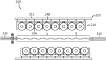
도 2는 도 1의 배터리 모듈 조립체의 조립 시스템의 얼라인 장치를 설명하기 위한 개략적인 도면이며, 도 3은 도 2의 얼라인 장치의 주요부를 설명하기 위한 도면이며, 도 4는 도 2의 얼라인 장치의 개략적인 단면도이다.FIG. 2 is a schematic diagram for explaining an aligning device of the battery module assembly assembly system of FIG. 1 , FIG. 3 is a diagram for explaining main parts of the aligning device of FIG. 2 , and FIG. This is a schematic cross-section of the device.
도 2 내지 도 4 및 앞선 도 1을 참조하면, 상기 얼라인 장치(200)는, 가이드 지그(210), 셀 간격 조정 지그(220) 및 쿨링 유닛 그립퍼(230)를 포함할 수 있다.Referring to FIGS. 2 to 4 and FIG. 1 , the
상기 가이드 지그(210)는, 상기 2열의 배터리 셀들(3)을 지지하기 위한 것으로서, 한 쌍으로 구비될 수 있다. 상기 한 쌍의 가이드 지그(210)는, 각 열의 배터리 셀들(3)을 지지할 수 있게 마련될 수 있다.The
상기 셀 간격 조정 지그(220)는, 상기 한 쌍의 가이드 지그(210)와 연결되며, 각 열의 배터리 셀들(3)의 간격을 조정할 수 있다. 이러한 상기 셀 간격 조정 지그(220)는, 한 쌍으로 구비되며, 각각의 가이드 지그(210)에 슬라이딩 가능하게 장착될 수 있다.The cell
상기 쿨링 유닛 그립퍼(230)는, 상기 한 쌍의 가이드 지그(210) 사이에 상기 쿨링 유닛(5)을 배치시킬 수 있다. 이러한 상기 쿨링 유닛 그립퍼(230)는, 한 쌍으로 구비되며, 상기 쿨링 유닛(5)의 양단부를 지지할 수 있다.The cooling
이러한 본 실시예에 따른 상기 얼라인 장치(200)는, 상기 2열의 배터리 셀들(3)을 기립 상태로 상기 쿨링 유닛(5)을 사이에 두고 배치시킨 상태에서 상기 가이드 지그(210) 및 셀 간격 조정 지그(220)의 슬라이딩 동작으로 상기 2열의 배터리 셀들(3)의 간격을 조정할 수 있다.In the
구체적으로, 상기 한 쌍의 가이드 지그(210)는, 상기 쿨링 유닛 그립퍼(230)를 향한 방향 및 상기 쿨링 유닛 그립퍼(226)의 반대 방향을 따라 슬라이딩 가능하게 구비될 수 있다. 즉, 상기 한 쌍의 가이드 지그(210)는, 각 열의 배터리 셀들(3)을 지지한 상태에서 상기 쿨링 유닛(5)를 향한 방향 및 상기 쿨링 유닛(5)의 반대 방향을 따라 슬라이딩 가능하게 구비될 수 있다.Specifically, the pair of guide jigs 210 may be slidably provided along a direction toward the cooling
여기서, 상기 한 쌍의 가이드 지그(210)는, 상기 슬라이딩을 통해, 상기 각 열의 배터리 셀들(3)을 가압하여 상기 각 열의 배터리 셀들(3)을 상기 쿨링 유닛(5)의 양측면에 밀착시킬 수 있다.Here, the pair of
상기 셀 간격 조정 지그(220)는, 한 쌍으로 구비되고, 상기 한 쌍의 가이드 지그(210)의 일측에 슬라이딩 가능하게 장착되며, 상기 슬라이딩 시 적어도 일부가 상기 한 쌍의 가이드 지그(210)를 관통하여 상기 각 열의 배터리 셀들(3) 사이에 슬라이딩되면서 상기 각 열의 배터리 셀들(3)의 간격을 조정할 수 있다.The cell
이러한 상기 한 쌍의 셀 간격 조정 지그(220)는, 각각, 조정 지그 본체(222) 및 간격 조정부(226)를 포함할 수 있다.Each of the pair of cell
상기 조정 지그 본체(222)는, 각각의 가이드 지그(210)의 일측에 슬라이딩 가능하게 장착될 수 있다. 이러한 상기 조정 지그 본체(222)는, 상기 가이드 지그(210)를 사이에 두고 상기 배터리 셀들(3)과 대향 배치될 수 있다.The
상기 간격 조정부(226)는, 복수 개로 구비되고, 상기 조정 지그 본체(222)로부터 소정 길이로 돌출되며, 상기 슬라이딩 시 각각의 가이드 지그(210)를 관통하여 상기 각 열의 배터리 셀들(3) 사이에 슬라이딩되어 각 열의 배터리 셀들(3)의 간격을 소정 간격으로 벌릴 수 있다.The
이러한 상기 복수 개의 간격 조정부(226)는, 상기 조정 지그 본체(222)의 길이 방향을 따라 상호 등 간격으로 소정 거리 이격 배치될 수 있다. 이에 따라, 상기 복수 개의 간격 조정부(226)의 슬라이딩 동작에 따라, 각 열의 배터리 셀들(3) 사이의 간격도 등 간격으로 조정될 수 있다.The plurality of spacing adjusting
상기 얼라인 장치(200)는, 셀 지지부(240)를 포함할 수 있다.The aligning
상기 셀 지지부(240)는, 상기 한 쌍의 가이드 지그(210)에 구비되며, 상기 배터리 셀들(3)을 지지할 수 있다. 이러한 상기 셀 지지부(240)는, 상기 한 쌍의 가이드 지그(210)에 안착되는 배터리 셀들(3)을 보다 더 안정적으로 지지하는 것을 가이드 할 수 있다.The
상기 셀 지지부(240)는, 자성부재로 구비될 수 있다. 이러한 상기 셀 지지부(240)는 복수 개로 구비될 수 있다. 상기 복수 개의 셀 지지부(240)는, 상기 가이드 지그(210)에 상기 배터리 셀들(3)의 안착 시 상기 배터리 셀들(3)과 마주 하는 위치에 구비될 수 있다.The
상기 얼라인 장치(200)는, 얼라인 그립퍼(250)를 포함할 수 있다.The
상기 얼라인 그립퍼(250)는, 상기 한 쌍의 가이드 지그(210) 상측에 구비되며, 상기 쿨링 유닛(5)을 사이에 두고 배치되는 2열의 배터리 셀들(3)의 상단을 가압하여 고정할 수 있다.The
이러한 상기 얼라인 그립퍼(250)는, 상기 셀 어셈블리(7)의 조립 시, 상기 배터리 셀들(3)과 상기 쿨링 유닛(5)의 상측 부분에서의 결합 견고성을 보다 더 높일 수 있다.When assembling the
아울러, 상기 얼라인 그립퍼(250)는, 상기 배터리 셀들(3)과 상기 쿨링 유닛(5)으로 마련되는 상기 셀 어셈블리(7)의 후속 공정 이송을 가이드 할 수 있다.In addition, the
이러한 상기 얼라인 장치(200)는, 상기 2열의 배터리 셀들(3) 사이에 상기 쿨링 유닛(5)을 상호 정렬과 함께 상호 접착하여 상기 셀 어셈블리(7)를 형성할 수 있다.The
다시 도 1을 참조하면, 상기 제2 이송 장치(300)는, 상기 배터리 모듈 조립체(1, 도 30 참조)의 조립 시스템(10)의 천장을 따라 이동 가능하게 구비될 수 있다.Referring back to FIG. 1 , the
구체적으로, 상기 제2 이송 장치(300)는, 상기 제1 이송 장치(100)의 상기 승강 유닛(150)과 같이 상기 천장 레일(600)에 슬라이딩 가능하게 장착될 수 있다. 아울러, 상기 제2 이송 장치(300)는, 상기 제1 이송 장치(100)의 상기 승강 유닛(150)과 같이 수직 방향으로 승하강 가능하게 구비될 수 있다.Specifically, the
한편, 상기 제2 이송 장치(300)는, 상기 승강 유닛(150)과 통합하여 구비되는 것도 가능할 수 있다. 즉, 상기 제2 이송 장치(300)는, 상기 제1 이송 장치(100)의 상기 승강 유닛(150)과 하나의 승강체로 마련되는 것도 가능할 수 있다.Meanwhile, the
상기 제2 이송 장치(300)는, 상기 이송 시 상기 셀 어셈블리(7)를 상온에서 경화시킬 수 있다. 이를 위해, 상기 제2 이송 장치(300)는, 상기 셀 어셈블리(7)의 상온 경화를 위한 구성 부품 등이 마련될 수 있다.The
본 실시예에서는, 상기 셀 어셈블리(7)의 경화 공정을, 상기 천장 레일(600)에 구비되는 상기 제2 이송 장치(300)의 이송 중 수행할 수 있어, 경화 공정에 따른 공간을 절약함과 아울러 조립 공정 택타임을 줄여 조립 공정 시간을 보다 더 단축시킬 수 있다.In this embodiment, the curing process of the
상기 제2 이송 장치(300)는, 상기 이송 시, 상기 셀 어셈블리(7)의 방향 전환 없이 상기 얼라인 장치(200)로부터 상기 셀 어셈블리(7)를 들어 올려 이송할 수 있다. 이에 따라, 본 실시예에서는, 상기 이송 시, 상기 셀 어셈블리(7)의 배터리 셀들(3)의 투입 방향 조정 등을 위한 회전 공정이 따로 요구되지 않아, 공 효율을 보다 더 높일 수 있다.The
상기 스트럭처 조립 장치(400)는, 상기 제2 이송 장치(300)를 통해 이송된 적어도 하나의 셀 어셈블리(7)의 상기 배터리 셀들(3) 사이 사이에 복수 개의 사이드 스트럭처 유닛들(9)을 배치시켜 상기 배터리 모듈 조립체(1)를 형성할 수 있다.The
구체적으로, 상기 스트럭처 조립 장치(400)는, 상기 복수 개의 사이드 스트럭처 유닛들(9)과 상기 적어도 하나의 셀 어셈블리(7)를 상호 접착시켜 상기 배터리 모듈 조립체(1)를 형성할 수 있다.Specifically, the
본 실시예에서는, 상기 스트럭처 조립 장치(400)를 통해, 상기 배터리 셀들(3), 상기 쿨링 유닛(5) 및 상기 사이드 스트럭처 유닛들(9)로 마련되는 상기 배터리 모듈 조립체(1)를 조립할 수 있다.In this embodiment, the
이하, 이러한 상기 스트럭처 조립 장치(400)에 대해 보다 더 구체적으로 살펴 본다.Hereinafter, the
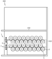
도 5는 도 1의 배터리 모듈 조립체의 조립 시스템의 스트럭처 조립 장치를 설명하기 위한 개략적인 도면이다.FIG. 5 is a schematic diagram for explaining a structure assembly device of the battery module assembly assembly system of FIG. 1 .
도 5 및 앞선 도 1을 참조하면, 상기 스트럭처 조립 장치(400)는, 조립 베이스(410) 및 슬라이딩 지그(430)를 포함할 수 있다.Referring to FIG. 5 and FIG. 1 , the
상기 조립 베이스(410)는, 상기 배터리 모듈 조립체(1)를 형성하기 위한 적어도 하나의 상기 셀 어셈블리(7) 및 적어도 하나의 상기 사이드 스트럭처 유닛(9)의 정렬을 가이드할 수 있다.The
상기 슬라이딩 지그(430)는, 상기 조립 베이스(410)에 슬라이딩 가능하게 구비되며, 상기 슬라이딩을 통해 적어도 하나의 상기 셀 어셈블리(7) 및 적어도 하나의 상기 사이드 스트럭처 유닛(9)을 상호 밀착시킬 수 있다.The sliding
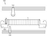
도 6은 도 1의 배터리 모듈 조립체의 조립 시스템의 프리 워킹 장치를 설명하기 위한 개략적인 도면이다.Figure 6 is a schematic diagram for explaining a free working device of the assembly system of the battery module assembly of Figure 1;
도 6 및 앞선 도 1을 참조하면, 상기 프리 워킹 장치(500)는, 상기 얼라인 장치()를 통한 셀 어셈블리(7)의 조립 및 상기 스트럭처 조립 장치(400)를 통한 배터리 모듈 조립체(1)의 조립 공정 이전에, 상기 쿨링 유닛(3) 및 상기 사이드 스트럭처 유닛(9)의 전처리 공정을 수행할 수 있다.Referring to FIG. 6 and the preceding FIG. 1 , the
이러한 상기 프리 워킹 장치(500)는, 플라즈마 처리부(510), 접착제 처리부(530) 및 방향 전환부(550)를 포함할 수 있다.The
상기 플라즈마 처리부(510)는, 상기 쿨링 유닛(5) 측으로의 플라즈마(P) 처리를 위한 것으로서, 상기 쿨링 유닛(5)의 길이 방향을 따라 슬라이딩 가능하게 마련될 수 있다.The
상기 접착제 처리부(530)는, 상기 쿨링 유닛(5) 및 상기 사이드 스트럭처 유닛(9)의 접착제(G) 도포를 위한 것으로서, 상기 쿨링 유닛(5) 및 상기 사이드 스트럭처 유닛(9)의 길이 방향을 따라 슬라이딩 가능하게 마련될 수 있다.The
상기 방향 전환부(550)는, 상기 플라즈마(P) 처리 및 상기 접착제(G) 도포를 가이드 함과 아울러 상기 플라즈마(P) 처리 또는 상기 접착제(G) 도포 시, 상기 쿨링 유닛(5) 또는 상기 사이드 스트럭처 유닛(9)을 지지할 수 있다.The
이러한 상기 방향 전환부(550)는, 상기 쿨링 유닛(5) 또는 상기 사이드 스트럭처 유닛(9)의 양측면 모두에 상기 플라즈마(P) 처리 또는 상기 접착제(G) 도포를 가능할 수 있게 상기 쿨링 유닛(5) 또는 상기 사이드 스트럭처 유닛(9)의 방향을 전환시킬 수 있다.The
한편, 상기 조립 시스템(10)은, 상기 천장 레일(600)을 포함할 수 있다.Meanwhile, the
다시 도 1을 참조하면, 상기 천장 레일(600)은, 상기 조립 시스템(10)의 천장부에 마련되며, 상기 제1 이송 장치(100)의 상기 승강 유닛(150) 및 상기 제2 이송 장치(300)의 슬라이딩 동작을 가이드 할 수 있다.Referring back to FIG. 1 , the
본 실시예에 따른 상기 조립 시스템(10)은, 시스템 천장부에 상기 이송 등을 가이드 하기 위한 상기 천장 레일(600)이 마련되는 바, 전체 시스템의 공간 활용을 극대화하여 시스템 장비 구축을 위한 공간을 절약할 수 있다.In the assembling
이하에서는, 이러한 본 실시예에 따른 상기 배터리 모듈 조립체(1)의 조립 시스템(10)을 통한 상기 배터리 모듈 조립체(1)의 조립 공정에 대해 보다 더 구체적으로 살펴 본다.Hereinafter, the assembly process of the
도 7 및 도 8은 도 1의 배터리 모듈 조립체의 조립 시스템의 제1 이송 장치의 동작을 설명하기 위한 도면이다.7 and 8 are views for explaining the operation of the first transfer device of the battery module assembly assembly system of FIG. 1 .
도 7 및 도 8을 참조하면, 상기 제1 이송 장치(100)의 상기 승강 장치(150)는, 상기 제1 컨베이어(110) 상의 상기 2열의 배터리 셀들(3)을 상기 제2 컨베이어(130) 측으로 이송할 수 있다.7 and 8 , the
여기서, 상기 승강 장치(150)는, 상기 제1 컨베이어(110) 상의 상기 2열의 배터리 셀들(3)을 흡착 등을 통해 들어 올린 후 상기 천장 레일(600)을 따라 상기 제2 컨베이어(110) 측으로 소정 거리 이동 후 하강하여 상기 제2 컨베이어(130) 상에 안착시킬 수 있다.Here, the
도 9 내지 도 13은 도 1의 배터리 모듈 조립체의 조립 시스템의 얼라인 장치의 동작을 설명하기 위한 도면이다.9 to 13 are views for explaining the operation of the alignment device of the battery module assembly assembly system of FIG. 1 .
도 9 내지 도 13을 참조하면, 상기 얼라인 장치(200)는, 상기 제1 이송 장치(100)로부터 이송된 2열의 배터리 셀들(3) 사이에 쿨링 유닛(5)을 배치시켜 상기 2열의 배터리 셀들(3)과 상기 쿨링 유닛(5)을 밀착시켜 상기 셀 어셈블리(7)를 형성할 수 있다.9 to 13 , the aligning
구체적으로, 도 9 내지 도 11을 참조하면, 상기 한 쌍의 가이드 지그(210)는, 각 열의 배터리 셀들(3)을 상기 쿨링 유닛(5)에 밀착시킬 수 있게 가압할 수 있다. 여기서, 상기 한 쌍의 셀 간격 조정 지그(220)는, 상기 가이드 지그(210)에 관통 슬라이딩되면서 각 열의 배터리 셀들(3) 사이 사이 간격을 조정할 수 있다.Specifically, referring to FIGS. 9 to 11 , the pair of guide jigs 210 may pressurize the
상기 쿨링 유닛(5)의 양측면에는, 상기 프리 워킹 장치(500)를 통해 접착제(G)가 도포되어 있는 바, 상기 밀착 시, 상기 배터리 셀들(3)과 상기 쿨링 유닛(5)이 상호 접착될 수 있다. 이러한 상기 배터리 셀들(3)과 상기 쿨링 유닛(5) 사이의 상호 접착을 통해 상기 셀 어셈블리(7)가 형성될 수 있다.Adhesive G is applied to both side surfaces of the
도 12 및 도 13을 참조하면, 상기 한 쌍의 가이드 지그(210)는, 상기 셀 어셈블리(7)로부터 멀어지는 방향으로 슬라이딩될 수 있으며, 상기 얼라인 그립퍼(250)는, 상기 셀 어셈블리(7)의 상단부 양측을 가압할 수 있다. 이에 따라, 상기 셀 어셈블리(7)의 상단부에서의 상기 배터리 셀들(3)과 상기 쿨링 유닛(5)의 결합 견고성을 보다 더 높일 수 있다. 이후, 상기 얼라인 그립퍼(250)는, 상기 셀 어셈블리(7)를 들어 올려 상기 셀 어셈블리(7)를 후속 공정으로 안내할 수 있다.12 and 13 , the pair of guide jigs 210 may slide in a direction away from the
도 14 내지 도 16은 도 1의 배터리 모듈 조립체의 조립 시스템의 다른 실시예에 따른 얼라인 장치의 동작을 설명하기 위한 도면이다.14 to 16 are diagrams for explaining an operation of an align device according to another embodiment of the battery module assembly assembly system of FIG. 1 .
본 실시예에 따른 얼라인 장치(200)는, 앞선 실시예의 상기 얼라인 장치(205)와 유사하므로, 앞선 실시예와 실질적으로 동일하거나 또는 유사한 구성들에 대해서는 중복 설명을 생략하고, 이하, 앞선 실시예와의 차이점을 중심으로 살펴 본다.Since the aligning
도 14 내지 도 16을 참조하면, 상기 얼라인 장치(205)는, 상기 쿨링 유닛 그립퍼(230)를 사이에 두고 소정 각도로 틸팅 가능하게 구비되는 한 쌍의 가이드 지그(215)를 포함할 수 있다.14 to 16 , the aligning
상기 한 쌍의 가이드 지그(215)는, 상기 2열의 배터리 셀들(3)과 상기 쿨링 유닛(5)의 밀착 전에, 소정 각도로 경사지게 배치되어 각 열의 배터리 셀들(3)을 보다 더 안정적으로 지지할 수 있다.The pair of guide jigs 215 are inclined at a predetermined angle before the two rows of
이러한 상기 한 쌍의 가이드 지그(215)는, 상기 소정 각도로 틸팅되면서 상기 각 열의 배터리 셀들(3)을 상기 쿨링 유닛(5) 측으로 밀착되게끔 가압할 수 있다.The pair of guide jigs 215 may press the
이처럼, 상기 한 쌍의 가이드 지그(215)는, 슬라이딩 동작과 함께 틸팅 동작을 모두 구현할 수 있게 구비되어, 상기 정렬이나 가압 동작 시, 상기 2열의 배터리 셀들(3)을 보다 더 안정적으로 지지할 수 있다.As such, the pair of guide jigs 215 are provided to implement both sliding and tilting operations, so that the two rows of
도 17 및 도 18은 도 1의 배터리 모듈 조립체의 조립 시스템의 제2 이송 장치의 동작을 설명하기 위한 도면이다.17 and 18 are views for explaining the operation of the second transfer device of the battery module assembly assembly system of FIG. 1 .
도 17 및 도 18을 참조하면, 상기 제2 이송 장치(300)는, 상기 얼라인 장치(200)로부터 상기 셀 어셈블리(7)를 들어 올려 상기 스트럭처 조립 장치(400) 측으로 이송할 수 있다.17 and 18 , the
상기 제2 이송 장치(300)는, 이러한 이송 동작 시, 상기 셀 어셈블리(7)를 상온에서 경화시켜 상기 셀 어셈블리(7)의 결합 견고성을 보다 더 높일 수 있다. 이처럼, 본 실시예에서는, 상기 제2 이송 장치(300)의 이송 시, 상기 셀 어셈블리(7)를 경화시킬 수 있어, 조립 고정 효율이 보다 더 향상될 수 있다.The
도 19 내지 도 23은 도 1의 배터리 모듈 조립체의 조립 시스템의 프리 워킹 장치를 통한 쿨링 유닛의 선 가공 동작을 설명하기 위한 도면이다.19 to 23 are views for explaining a pre-processing operation of a cooling unit through a free-working device of the battery module assembly assembly system of FIG. 1 .
도 19 내지 도 23을 참조하면, 상기 프리 워킹 장치(500)는, 상기 쿨링 유닛(5)의 상기 얼라인 장치(200) 측으로의 이송 전 전처리 공정을 수행할 수 있다.19 to 23 , the
먼저, 상기 프리 워킹 장치(500)의 상기 플라즈마 처리부(510)는, 상기 쿨링 유닛(5)의 길이 방향을 따라 슬라이딩되면서 상기 쿨링 유닛(5)의 양측면 중 일측면을 플라즈마(P) 처리할 수 있다.First, the
이후, 상기 프리 워킹 장치(500)의 상기 접착제 처리부(530)는, 상기 쿨링 유닛(5)의 길이 방향을 따라 슬라이딩되면서 상기 쿨링 유닛(5)의 양측면 중 일측면에 상기 접착제(G)를 도포할 수 있다.Thereafter, the
상기 쿨링 유닛(5)의 양측면 중 일측면에 상기 플라즈마(P) 처리 및 상기 접착제(G) 도포가 완료되면, 상기 방향 전환부(550)는, 상기 쿨링 유닛(5)의 방향을 전환시킬 수 있다.When the plasma (P) treatment and the application of the adhesive (G) are completed on one of both side surfaces of the cooling unit (5), the direction changing unit (550) may change the direction of the cooling unit (5). there is.
이후, 상기 프리 워킹 장치(500)의 상기 플라즈마 처리부(510)는, 상기 쿨링 유닛(5)의 길이 방향을 따라 슬라이딩되면서 상기 쿨링 유닛(5)의 양측면 중 타측면을 플라즈마(P) 처리할 수 있다.Thereafter, the
그리고, 상기 프리 워킹 장치(500)의 상기 접착제 처리부(530)는, 상기 쿨링 유닛(5)의 길이 방향을 따라 슬라이딩되면서 상기 쿨링 유닛(5)의 양측면 중 타측면에 상기 접착제(G)를 도포할 수 있다.In addition, the
이후, 상기 프리 워킹 장치(500)는, 양측면 모두에 상기 플라즈마(P) 처리 및 상기 접착제(G) 도포가 수행된 상기 쿨링 유닛(5)을 상기 얼라인 장치(200) 측으로 이송할 수 있다.Thereafter, the
도 24 내지 도 26은 도 1의 배터리 모듈 조립체의 조립 시스템의 프리 워킹 장치를 통한 사이드 스트럭처 유닛의 선 가공 동작을 설명하기 위한 도면이다.24 to 26 are views for explaining a pre-processing operation of a side structure unit through a free-working device of the battery module assembly assembly system of FIG. 1 .
도 24 내지 도 26을 참조하면, 상기 프리 워킹 장치(500)는, 상기 사이드 스트럭처 유닛(9)의 상기 스트럭처 조립 장치(400) 측으로의 이송 전 전처리 공정을 수행할 수 있다.24 to 26 , the
먼저, 상기 프리 워킹 장치(500)의 상기 접착제 처리부(530)는, 상기 사이드 스트럭처 유닛(9)의 길이 방향을 따라 슬라이딩되면서 상기 사이드 스트럭처 유닛(9)의 양측면 중 일측면에 상기 접착제(G)를 도포할 수 있다.First, the
상기 사이드 스트럭처 유닛(9)의 양측면 중 일측면에 상기 접착제(G) 도포가 완료되면, 상기 방향 전환부(550)는, 상기 사이드 스트럭처 유닛(9)의 방향을 전환시킬 수 있다.When the application of the adhesive (G) is completed on one of both side surfaces of the
이후, 상기 프리 워킹 장치(500)의 상기 접착제 처리부(530)는, 상기 사이드 스트럭처 유닛(9)의 길이 방향을 따라 슬라이딩되면서 상기 사이드 스트럭처 유닛(9)의 양측면 중 타측면에 상기 접착제(G)를 도포할 수 있다.Thereafter, the
이후, 상기 프리 워킹 장치(500)는, 양측면 모두에 상기 접착제(G) 도포가 수행된 상기 사이드 스트럭처 유닛(9)을 상기 스트럭처 조립 장치(400) 측으로 이송할 수 있다.Thereafter, the
도 27 내지 도 29는 도 1의 배터리 모듈 조립체의 조립 시스템의 스트럭처 조립 장치의 동작을 설명하기 위한 도면이다.27 to 29 are views for explaining the operation of the structure assembling device of the battery module assembly assembly system of FIG. 1 .
도 27 내지 도 29를 참조하면, 상기 스트럭처 조립 장치(400)는, 상기 조립 베이스(410)는, 상기 사이드 스트럭처 유닛(9)들, 상기 셀 어셈블리(7)들을 교대로 배치되게 정렬시킬 수 있다.27 to 29, in the
상기 슬라이딩 지그(430)는, 상기 조립 베이스(410)를 따라 슬라이딩되면서 상기 사이드 스트럭처 유닛(9)들과 상기 셀 어셈블리(7)들을 밀착시킬 수 있다. 이에 따라, 상기 사이드 스트럭처 유닛(9)들과 상기 셀 어셈블리(7)들은 상호 밀착되면서 상호 접착되어 상기 배터리 모듈 조립체(1)를 형성할 수 있다.The sliding
이하, 전술한 상기 조립 시스템(10)을 통한 조립 공정을 통한 본 발명의 배터리 모듈 조립체(1)의 조립 방법에 대해 구체적으로 살펴 본다.Hereinafter, a method of assembling the
본 실시예에서, 상기 배터리 모듈 조립체(1, 도 30 참조)의 조립 방법은, 복수 개의 배터리 셀들(3)을 2열로 이송하는 단계, 상기 2열로 이송된 배터리 셀들(3) 사이에 쿨링 유닛(5)을 정렬하여 셀 어셈블리(7)를 조립하는 단계, 상기 셀 어셈블리(7)를 상기 셀 어셈블리(7)의 상기 배터리 셀들(3)을 커버하는 사이드 스트럭처 유닛(9) 측으로 이송하는 단계 및 상기 셀 어셈블리(7)의 상기 배터리 셀들(3)을 상기 사이드 스트럭처 유닛(9)으로 커버하여 상기 배터리 모듈 조립체(1)를 조립하는 단계를 포함할 수 있다.In this embodiment, the assembly method of the battery module assembly (1, see FIG. 30) includes the steps of transferring a plurality of
여기서, 상기 복수 개의 배터리 셀들(3)을 2열로 이송하는 단계는, 상기 상부 컨베이어(110)를 통해 상기 2열의 배터리 셀들(3)을 이송하는 단계 및 상기 상부 컨베이어(110)의 상기 2열의 배터리 셀들(3)을 상기 셀 어셈블리(7)를 조립하기 위한 하부 컨베이어(130)로 이송하는 단계를 포함할 수 있다.Here, the step of transferring the plurality of
여기서, 상기 셀 어셈블리(7)는, 상기 2열의 배터리 셀들(3) 사이에 정렬된 상기 쿨링 유닛(5)을 접착제(G)를 통해 상기 2열의 배터리 셀들(3)과 상호 접착하여 형성될 수 있다.Here, the
그리고, 상기 배터리 모듈 조립체(1)는, 상기 셀 어셈블리(7)의 상기 배터리 셀들(3)을 상기 사이드 스트럭처 유닛(9)과 접착제(G)를 통해 상호 접착하여 형성될 수 있다.Also, the
한편, 상기 셀 어셈블리(7)는, 상기 사이드 스트럭처 유닛(9) 측으로 이송 시 상온에서 경화될 수 있다. 이에 따라, 상기 셀 어셈블리(7)의 상기 배터리 셀들(3)과 상기 쿨링 유닛(5)는, 상기 사이드 스트럭처 유닛(9)과의 조립 이전에 서로 보다 더 단단히 결합될 수 있다. 아울러, 상기 셀 어셈블리는, 상기 사이드 스트럭처 유닛(9) 측으로 이송 시 천장을 따라 상기 사이드 스트럭처 유닛(9) 측으로 이송될 수 있다.Meanwhile, the
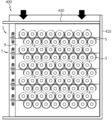
도 30은 도 1의 배터리 모듈 조립체의 조립 시스템을 통해 조립된 배터리 모듈 조립체를 설명하기 위한 도면이다.FIG. 30 is a view for explaining a battery module assembly assembled through the battery module assembly assembly system of FIG. 1 .
도 30을 참조하면, 본 실시예에 따른 상기 배터리 모듈 조립체(1)는, 배터리 셀들(3) 사이에 쿨링 유닛(5)을 구비하는 복수 개의 셀 어셈블리(7) 및 상기 복수 개의 셀 어셈블리(7) 사이에 구비되며, 상기 배터리 모듈 조립체(1)의 최외곽 양측면을 형성하는 복수 개의 사이드 스트럭처 유닛(9)을 포함할 수 있다.Referring to FIG. 30 , the
이러한 상기 배터리 모듈 조립체(1)는, 복수 개의 셀 어셈블리(7) 및 복수 개의 사이드 스트럭처 유닛(9) 만으로 형성되는 바, 종래의 같은 프레임 구조 없이 프레임 리스 구조를 구현할 수 있다.Since the
본 실시예에 따른 상기 조립 시스템(10)을 통해 제조되는 상기 배터리 모듈 조립체(1)는, 프레임 리스 구조로 마련되는 바, 종래 프레임 구조에 대해 보다 슬림하고 상대적으로 높은 에너지 밀도를 확보할 수 있다.The
이상과 같은 다양한 실시예들에 따라, 프레임 리스 구조를 구현할 수 있는 배터리 모듈 조립체(1)의 조립 시스템(10) 및 조립 방법을 제공할 수 있다.According to various embodiments as described above, it is possible to provide an
또한, 이상과 같은 다양한 실시예들에 따라, 제조 비용을 절감하고 조립 공간을 최소화할 수 있는 배터리 모듈 조립체(1)의 조립 시스템(10) 및 조립 방법을 제공할 수 있다.In addition, according to various embodiments as described above, it is possible to provide an
이상과 같이, 본 발명은 비록 한정된 실시예와 도면에 의해 설명되었으나, 본 발명은 이것에 의해 한정되지 않으며 본 발명이 속하는 기술분야에서 통상의 지식을 가진 자에 의해 본 발명의 기술사상과 아래에 기재될 특허청구범위의 균등범위 내에서 다양한 수정 및 변형이 가능함은 물론이다.As described above, although the present invention has been described by the limited embodiments and drawings, the present invention is not limited thereto, and the technical spirit of the present invention and the following by those skilled in the art to which the present invention belongs Of course, various modifications and variations are possible within the scope of equivalents of the claims to be described.
1: 배터리 모듈 조립체
3: 배터리 셀
5: 쿨링 유닛
7: 셀 어셈블리
9: 사이드 스트럭처 유닛
10: 조립 시스템
100: 제1 이송 장치
110: 상부 컨베이어
130: 하부 컨베이어
150: 승강 유닛
200: 얼라인 장치
205: 얼라인 장치
210: 가이드 지그
215: 가이드 지그
220: 셀 간격 조정 지그
222: 조정 지그 본체
226: 간격 조정부
230: 쿨링 유닛 그립퍼
240: 셀 지지부
250: 얼라인 그립퍼
300: 제2 이송 장치
400: 스트럭처 조립 장치
410: 조립 베이스
430: 슬라이딩 지그
500: 프리 워킹 장치
510: 플라즈마 처리부
530: 접착제 처리부
550: 방향 전환부
600: 천장 레일1: battery module assembly 3: battery cell
5: cooling unit 7: cell assembly
9: side structure unit 10: assembly system
100: first transfer device 110: upper conveyor
130: lower conveyor 150: lifting unit
200: align device 205: align device
210: guide jig 215: guide jig
220: cell spacing adjustment jig 222: adjustment jig body
226: gap adjustment unit 230: cooling unit gripper
240: cell support 250: align gripper
300: second transfer device 400: structure assembly device
410: assembly base 430: sliding jig
500: free working device 510: plasma processing unit
530: adhesive treatment unit 550: direction conversion unit
600: ceiling rail
Claims (15)
복수 개의 배터리 셀들을 2열로 이송하는 제1 이송 장치;
상기 제1 이송 장치를 통해 이송된 2열의 배터리 셀들 사이에 쿨링 유닛을 정렬하여 셀 어셈블리를 조립하는 얼라인 장치; 및
상기 얼라인 장치에 의해 조립된 상기 셀 어셈블리를 상기 배터리 셀들을 커버하는 사이드 스트럭처 유닛와의 조립을 위한 스트럭처 조립 장치 측으로 이송하는 제2 이송 장치
를 포함하는 것을 특징으로 하는 배터리 모듈 조립체의 조립 시스템.In the assembly system of the battery module assembly,
A first transfer device for transferring a plurality of battery cells in two rows;
an alignment device for assembling a cell assembly by aligning a cooling unit between the two rows of battery cells transported through the first transfer device; and
A second transport device for transporting the cell assembly assembled by the align device to a structure assembly device for assembly with a side structure unit covering the battery cells.
Assembly system of the battery module assembly, characterized in that it comprises a.
상기 제1 이송 장치는,
상기 2열의 배터리 셀들을 이송하는 상부 컨베이어; 및
상기 2열의 배터리 셀들을 상기 얼라인 장치로 안내하는 하부 컨베이어를 포함하는 것을 특징으로 하는 것을 배터리 모듈 조립체의 조립 시스템.According to claim 1,
The first transport device,
an upper conveyor transporting the two rows of battery cells; and
The assembly system of the battery module assembly, characterized in that it comprises a lower conveyor for guiding the two rows of battery cells to the alignment device.
상기 제1 이송 장치는,
상기 상부 컨베이어와 상기 하부 컨베이어 사이에서 승하강 가능하며, 상기 상부 컨베이어의 상기 2열의 배터리 셀들을 상기 하부 컨베이어로 이송시키는 승강 유닛을 포함하는 것을 특징으로 하는 배터리 모듈 조립체의 조립 시스템.According to claim 2,
The first transport device,
The assembly system of a battery module assembly, characterized in that it comprises a lifting unit capable of moving up and down between the upper conveyor and the lower conveyor, and transferring the battery cells of the two rows of the upper conveyor to the lower conveyor.
상기 얼라인 장치는,
상기 2열의 배터리 셀들 사이에 상기 쿨링 유닛을 상호 접착하여 상기 셀 어셈블리를 형성하는 것을 특징으로 하는 배터리 모듈 조립체의 조립 시스템.According to claim 1,
The aligning device,
The assembly system of the battery module assembly, characterized in that the cell assembly is formed by mutually bonding the cooling unit between the two rows of battery cells.
상기 제2 이송 장치는,
상기 배터리 모듈 조립체의 조립 시스템의 천장을 따라 이동 가능하게 구비되는 것을 특징으로 하는 배터리 모듈 조립체의 조립 시스템.According to claim 1,
The second transport device,
The assembly system of the battery module assembly, characterized in that provided movably along the ceiling of the assembly system of the battery module assembly.
상기 제2 이송 장치는,
상기 이송 시 상기 셀 어셈블리를 상온에서 경화시키는 것을 특징으로 하는 배터리 모듈 조립체의 조립 시스템.According to claim 1,
The second transport device,
The assembly system of the battery module assembly, characterized in that for curing the cell assembly at room temperature during the transfer.
상기 제2 이송 장치는,
상기 셀 어셈블리의 방향 전환 없이 상기 셀 어셈블리를 들어 올려 이송하는 것을 특징으로 하는 배터리 모듈 조립체의 조립 시스템.According to claim 1,
The second transport device,
The assembly system of the battery module assembly, characterized in that for lifting and transporting the cell assembly without changing the direction of the cell assembly.
상기 배터리 모듈 조립체의 조립 시스템은,
상기 제2 이송 장치를 통해 이송된 적어도 하나의 셀 어셈블리의 상기 배터리 셀들 사이 사이에 복수 개의 사이드 스트럭처 유닛들을 배치시켜 상기 배터리 모듈 조립체를 형성하는 상기 스트럭처 조립 장치를 더 포함하는 것을 특징으로 하는 배터리 모듈 조립체의 조립 시스템.According to claim 1,
The assembly system of the battery module assembly,
The battery module further comprising the structure assembly device for forming the battery module assembly by arranging a plurality of side structure units between the battery cells of the at least one cell assembly transported through the second transport device. The assembly system of the assembly.
상기 스트럭처 조립 장치는,
상기 복수 개의 사이드 스트럭처 유닛들과 상기 적어도 하나의 셀 어셈블리를 상호 접착시키는 것을 특징으로 하는 배터리 모듈 조립체의 조립 시스템.According to claim 8,
The structure assembly device,
The assembly system of the battery module assembly, characterized in that for mutually bonding the plurality of side structure units and the at least one cell assembly.
복수 개의 배터리 셀들을 2열로 이송하는 단계;
상기 2열로 이송된 배터리 셀들 사이에 쿨링 유닛을 정렬하여 셀 어셈블리를 조립하는 단계;
상기 셀 어셈블리를 상기 셀 어셈블리의 상기 배터리 셀들을 커버하는 사이드 스트럭처 유닛 측으로 이송하는 단계; 및
상기 셀 어셈블리의 상기 배터리 셀들을 상기 사이드 스트럭처 유닛으로 커버하여 상기 배터리 모듈 조립체를 조립하는 단계
를 포함하는 것을 특징으로 하는 배터리 모듈 조립체의 조립 방법.In the assembly method of the battery module assembly,
Transferring a plurality of battery cells in two rows;
assembling a cell assembly by arranging a cooling unit between the battery cells transferred in the second row;
transferring the cell assembly to a side structure unit covering the battery cells of the cell assembly; and
Assembling the battery module assembly by covering the battery cells of the cell assembly with the side structure unit
A method of assembling a battery module assembly comprising a.
상기 복수 개의 배터리 셀들을 2열로 이송하는 단계는,
상부 컨베이어를 통해 2열의 배터리 셀들을 이송하는 단계; 및
상기 상부 컨베이어의 2열의 배터리 셀들을 상기 셀 어셈블리를 조립하기 위한 하부 컨베이어로 이송하는 단계를 포함하는 것을 특징으로 하는 배터리 모듈 조립체의 조립 방법.According to claim 10,
The step of transferring the plurality of battery cells in two rows,
Transferring two rows of battery cells through an upper conveyor; and
and transferring the two rows of battery cells of the upper conveyor to a lower conveyor for assembling the cell assembly.
상기 셀 어셈블리는,
상기 2열의 배터리 셀들 사이에 정렬된 상기 쿨링 유닛을 접착제를 통해 상기 2열의 배터리 셀들과 상호 접착하여 형성되는 것을 특징으로 하는 배터리 모듈 조립체의 조립 방법.According to claim 10,
The cell assembly,
The method of assembling a battery module assembly, characterized in that formed by bonding the cooling unit aligned between the two rows of battery cells to each other with an adhesive.
상기 배터리 모듈 조립체는,
상기 셀 어셈블리의 상기 배터리 셀들을 상기 사이드 스트럭처 유닛과 접착제를 통해 상호 접착하여 형성되는 것을 특징으로 하는 배터리 모듈 조립체의 조립 방법.According to claim 10,
The battery module assembly,
The method of assembling a battery module assembly, characterized in that formed by mutually bonding the battery cells of the cell assembly with the side structure unit through an adhesive.
상기 셀 어셈블리는,
상기 사이드 스트럭처 유닛 측으로 이송 시 상온에서 경화되는 것을 특징으로 하는 배터리 모듈 조립체의 조립 방법.According to claim 10,
The cell assembly,
A method of assembling a battery module assembly, characterized in that cured at room temperature when transported to the side structure unit.
상기 셀 어셈블리는,
상기 사이드 스트럭처 유닛 측으로 이송 시 천장을 따라 상기 사이드 스트럭처 유닛 측으로 이송되는 것을 특징으로 하는 배터리 모듈 조립체의 조립 방법.According to claim 10,
The cell assembly,
The method of assembling a battery module assembly, characterized in that the transfer to the side structure unit side along the ceiling when transporting to the side structure unit side.
Applications Claiming Priority (4)
| Application Number | Priority Date | Filing Date | Title |
|---|---|---|---|
| KR20210174261 | 2021-12-07 | ||
| KR1020210174261 | 2021-12-07 | ||
| KR1020210189013 | 2021-12-27 | ||
| KR20210189013 | 2021-12-27 |
Publications (1)
| Publication Number | Publication Date |
|---|---|
| KR20230085870A true KR20230085870A (en) | 2023-06-14 |
Family
ID=86730868
Family Applications (1)
| Application Number | Title | Priority Date | Filing Date |
|---|---|---|---|
| KR1020220168021A KR20230085870A (en) | 2021-12-07 | 2022-12-05 | Assembly system and assembly method of battery module assembly |
Country Status (2)
| Country | Link |
|---|---|
| KR (1) | KR20230085870A (en) |
| WO (1) | WO2023106773A1 (en) |
Cited By (1)
| Publication number | Priority date | Publication date | Assignee | Title |
|---|---|---|---|---|
| KR102592629B1 (en) * | 2023-06-15 | 2023-10-25 | (주)홍진기업 | Method for manufacturing lithium battery pack |
Family Cites Families (5)
| Publication number | Priority date | Publication date | Assignee | Title |
|---|---|---|---|---|
| KR100388648B1 (en) * | 2001-05-23 | 2003-06-25 | 주식회사 코캄엔지니어링 | Automated manufacturing system of lithium secondary cell |
| KR102092108B1 (en) * | 2015-11-30 | 2020-03-23 | 주식회사 엘지화학 | Pallet Capable of Improving Productivity of Battery Pack and Battery Pack Assembling Apparatus Comprising the Same |
| KR20170071077A (en) * | 2015-12-15 | 2017-06-23 | 주식회사 엘지화학 | Apparatus for Manufacturing Battery Pack Having Plurality of Lanes for Assembling Battery Cells |
| KR20190124544A (en) * | 2018-04-26 | 2019-11-05 | 삼성에스디아이 주식회사 | Rechargeable battery, manufacturing apparatus and manufacturing metho of the same |
| KR102193318B1 (en) * | 2019-03-29 | 2020-12-22 | 주식회사 디에이테크놀로지 | Apparatus for Distributing Battery Cell Parts, And System for Manufacturing Secondary Battery Cell Having the Same |
-
2022
- 2022-12-05 KR KR1020220168021A patent/KR20230085870A/en active Search and Examination
- 2022-12-05 WO PCT/KR2022/019638 patent/WO2023106773A1/en unknown
Cited By (1)
| Publication number | Priority date | Publication date | Assignee | Title |
|---|---|---|---|---|
| KR102592629B1 (en) * | 2023-06-15 | 2023-10-25 | (주)홍진기업 | Method for manufacturing lithium battery pack |
Also Published As
| Publication number | Publication date |
|---|---|
| WO2023106773A1 (en) | 2023-06-15 |
Similar Documents
| Publication | Publication Date | Title |
|---|---|---|
| US11515563B2 (en) | Stacking apparatus and stacking method | |
| KR101124534B1 (en) | Secondary battery charging device for charging plural secondary battery | |
| KR20170117681A (en) | Taping Apparatus Capable of Attaching Adhesive Tape to Battery Cell | |
| KR102088272B1 (en) | Pressing Device for Battery Cell, Initial Charging and Discharging System for Battery Cell Using the Same, and Method of Initial Charging And Discharging Battery Cell Using the Same | |
| KR102043113B1 (en) | Secondary battery alignment jig and secondary battery stacking system including the same | |
| KR20210009779A (en) | Electrode Transfer Apparatus for Manufacturing Cell Stack of Secondary Battery | |
| KR102043902B1 (en) | Electrode Stacking Device for Secondary Cell | |
| KR20230085870A (en) | Assembly system and assembly method of battery module assembly | |
| CN111786027B (en) | Lithium battery shaping equipment | |
| KR102363196B1 (en) | Gripper for charging and discharging of pouch type battery, and charging and discharging device of pouch type battery having same | |
| KR102043112B1 (en) | Secondary battery cell rotating device | |
| WO2019139302A1 (en) | Battery module, and battery pack and vehicle comprising same | |
| KR20230085868A (en) | Align apparatus and assembly system of battery module assembly comprising the align apparatus | |
| US20230042766A1 (en) | Electrode lead gripper for pressure activation device | |
| KR20210119651A (en) | Transfer jig for loading battery pack into battery rack and battery rack loading method using same | |
| CN117652057A (en) | Battery module assembly assembling system and assembling method | |
| KR102361748B1 (en) | secondary battery cell transfer carrier | |
| KR102386470B1 (en) | charging and discharging device of pouch type battery | |
| KR101071547B1 (en) | An welding method for tap used for secondary battery | |
| KR101856819B1 (en) | System for manufacturing an electrode assembly | |
| CN211182381U (en) | Cell module transfer device | |
| KR20150043726A (en) | Device for automatically bending side wing of battery pack and method using the same | |
| JP2014035985A (en) | Partition plate and restraint method of storage element | |
| KR102531393B1 (en) | A apparatus for stacking the electrodes of secondary battery | |
| KR101287410B1 (en) | Electrode supplying apparatus for small polymer secondary battery manufacturing system |
Legal Events
| Date | Code | Title | Description |
|---|---|---|---|
| A201 | Request for examination |