KR20230066046A - Fairway wood golf club head with low CG - Google Patents
Fairway wood golf club head with low CG Download PDFInfo
- Publication number
- KR20230066046A KR20230066046A KR1020237011699A KR20237011699A KR20230066046A KR 20230066046 A KR20230066046 A KR 20230066046A KR 1020237011699 A KR1020237011699 A KR 1020237011699A KR 20237011699 A KR20237011699 A KR 20237011699A KR 20230066046 A KR20230066046 A KR 20230066046A
- Authority
- KR
- South Korea
- Prior art keywords
- inches
- club head
- golf club
- sole
- inch
- Prior art date
Links
Images


Classifications
-
- A—HUMAN NECESSITIES
- A63—SPORTS; GAMES; AMUSEMENTS
- A63B—APPARATUS FOR PHYSICAL TRAINING, GYMNASTICS, SWIMMING, CLIMBING, OR FENCING; BALL GAMES; TRAINING EQUIPMENT
- A63B53/00—Golf clubs
- A63B53/08—Golf clubs with special arrangements for obtaining a variable impact
-
- A—HUMAN NECESSITIES
- A63—SPORTS; GAMES; AMUSEMENTS
- A63B—APPARATUS FOR PHYSICAL TRAINING, GYMNASTICS, SWIMMING, CLIMBING, OR FENCING; BALL GAMES; TRAINING EQUIPMENT
- A63B53/00—Golf clubs
- A63B53/04—Heads
- A63B53/0408—Heads characterised by specific dimensions, e.g. thickness
-
- A—HUMAN NECESSITIES
- A63—SPORTS; GAMES; AMUSEMENTS
- A63B—APPARATUS FOR PHYSICAL TRAINING, GYMNASTICS, SWIMMING, CLIMBING, OR FENCING; BALL GAMES; TRAINING EQUIPMENT
- A63B53/00—Golf clubs
- A63B53/04—Heads
- A63B53/0433—Heads with special sole configurations
-
- A—HUMAN NECESSITIES
- A63—SPORTS; GAMES; AMUSEMENTS
- A63B—APPARATUS FOR PHYSICAL TRAINING, GYMNASTICS, SWIMMING, CLIMBING, OR FENCING; BALL GAMES; TRAINING EQUIPMENT
- A63B53/00—Golf clubs
- A63B53/04—Heads
- A63B53/0437—Heads with special crown configurations
-
- A—HUMAN NECESSITIES
- A63—SPORTS; GAMES; AMUSEMENTS
- A63B—APPARATUS FOR PHYSICAL TRAINING, GYMNASTICS, SWIMMING, CLIMBING, OR FENCING; BALL GAMES; TRAINING EQUIPMENT
- A63B53/00—Golf clubs
- A63B53/04—Heads
- A63B53/0466—Heads wood-type
-
- A—HUMAN NECESSITIES
- A63—SPORTS; GAMES; AMUSEMENTS
- A63B—APPARATUS FOR PHYSICAL TRAINING, GYMNASTICS, SWIMMING, CLIMBING, OR FENCING; BALL GAMES; TRAINING EQUIPMENT
- A63B60/00—Details or accessories of golf clubs, bats, rackets or the like
- A63B60/02—Ballast means for adjusting the centre of mass
-
- A—HUMAN NECESSITIES
- A63—SPORTS; GAMES; AMUSEMENTS
- A63B—APPARATUS FOR PHYSICAL TRAINING, GYMNASTICS, SWIMMING, CLIMBING, OR FENCING; BALL GAMES; TRAINING EQUIPMENT
- A63B53/00—Golf clubs
- A63B53/04—Heads
- A63B2053/0491—Heads with added weights, e.g. changeable, replaceable
-
- A—HUMAN NECESSITIES
- A63—SPORTS; GAMES; AMUSEMENTS
- A63B—APPARATUS FOR PHYSICAL TRAINING, GYMNASTICS, SWIMMING, CLIMBING, OR FENCING; BALL GAMES; TRAINING EQUIPMENT
- A63B2209/00—Characteristics of used materials
-
- A—HUMAN NECESSITIES
- A63—SPORTS; GAMES; AMUSEMENTS
- A63B—APPARATUS FOR PHYSICAL TRAINING, GYMNASTICS, SWIMMING, CLIMBING, OR FENCING; BALL GAMES; TRAINING EQUIPMENT
- A63B2209/00—Characteristics of used materials
- A63B2209/02—Characteristics of used materials with reinforcing fibres, e.g. carbon, polyamide fibres
-
- A—HUMAN NECESSITIES
- A63—SPORTS; GAMES; AMUSEMENTS
- A63B—APPARATUS FOR PHYSICAL TRAINING, GYMNASTICS, SWIMMING, CLIMBING, OR FENCING; BALL GAMES; TRAINING EQUIPMENT
- A63B53/00—Golf clubs
- A63B53/04—Heads
- A63B53/0416—Heads having an impact surface provided by a face insert
Abstract
본 발명은, 클럽 헤드의 낮은 무게 중심을 가능하게 함으로써 관용성을 증가시키며, 스핀을 감소시키며, 페어웨이 유형 골프 클럽 헤드의 포스 라인 임팩트 지점 축선에 또는 그 근처에 무게 중심을 위치 결정하기 위해, 경량 크라운 인서트, 중량 감소 특징의 본체, 고밀도 솔 인서트, 제거 가능하거나, 조정 가능하거나, 교체 가능한 후방 추 조립체, 또는 이들의 조합으로 구성되는 그룹으로부터 선택된 특징을 조합한(또는 포함하는) 페어웨이 유형 골프 클럽 헤드에 관한 것이다.The present invention provides a lightweight crown to increase forgiveness by enabling a low center of gravity in the club head, reduce spin, and position the center of gravity at or near the axis of the force line impact point of a fairway type golf club head. A fairway type golf club head incorporating (or including) a feature selected from the group consisting of an insert, a body with weight reducing features, a high density sole insert, a removable, adjustable or replaceable rear weight assembly, or a combination thereof. It is about.
Description
교차 참조 우선권Cross Reference Priority
본원은 2021 년 7 월 1 일에 출원된 미국 가출원 제 63/217,695 호 및 2020 년 9 월 10 일에 출원된 미국 가출원 제 63/076,766 호에 대한 우선권을 주장하며, 이들 출원 모두 전체적으로 본원에 인용된다.This application claims priority to U.S. Provisional Application No. 63/217,695, filed July 1, 2021, and U.S. Provisional Application No. 63/076,766, filed September 10, 2020, both of which are incorporated herein in their entirety. .
본 개시는 골프 장비에 관한 것으로서, 보다 상세하게는, 특정 질량 특성을 갖는 다중 재료 페어웨이 유형 골프 클럽에 관한 것이다.This disclosure relates to golf equipment and, more particularly, to multi-material fairway type golf clubs having specific mass characteristics.
드라이버를 사용할 때 골퍼는 자신의 선호도로 티(tee)의 높이를 설정하여 자신의 스윙에 맞게 공의 높이를 설정할 수 있다. 페어웨이 유형 클럽을 사용함으로써, 골퍼는 골프공 지면 라이(lie)가 존재하는 어떤 곳에서든지 공을 타격하고 있다. 기존의 골프공 라이에서 볼을 쳤을 때, 페어웨이 유형 골프 클럽 헤드의 전단 가장자리가 "공이 보는 것"이다. 즉, 페어웨이 유형 클럽의 솔의 바운스 깊이는 기본적으로, 골프공이 놓이는 실제 지면 아래에 있는데, 그 이유는 바운스가 흙을 파고 들어가 디보트(divot)를 생성하기 때문이다. 최적의 임팩트(impact)는 기본적으로 골프공이 놓이는 골프공의 높이와 관련하여 일정하기 때문에, 기본적으로 다양한 페어웨이 유형 골프 클럽 헤드의 바운스 깊이와 페이스 높이에 따라 변하지 않는다.When using the driver, the golfer can set the height of the tee to suit his or her swing. By using a fairway type club, the golfer is hitting the ball wherever the golf ball lies on the ground. When a ball is hit from a conventional golf ball lie, the shearing edge of a fairway type golf club head is what the ball sees. That is, the bounce depth of the sole of a fairway type club is basically below the actual ground level where the golf ball rests because the bounce cuts into the soil to create a divot. Since the optimal impact is basically constant with respect to the height of the golf ball at which it is placed, it basically does not change with the bounce depth and face height of various fairway type golf club heads.
이것은 결국, 최고의 힘 분급이, 특정 모델이 아니라 골프공 라이의 기하학적 구조에 의해 구동되며 또한 골프공 상의 특정 지점에서 충격력을 최대화하여 구동되는, 페어웨이 유형 골프 클럽 헤드의 축선을 따라 이루어진다는 것을 의미한다. 따라서, 페어웨이 유형 골프 클럽 헤드의 무게 중심(CG)을 해당 축선 상에 또는 가능한 한 해당 축선에 가깝게 배치하면, 임팩트 시에 골프공에 전달되는 힘이 최대화된다. This in turn means that the best force classification is along the axis of the fairway type golf club head, which is driven by the geometry of the golf ball lie and not by a specific model, and driven by maximizing the impact force at a specific point on the golf ball. . Therefore, placing the center of gravity (CG) of the fairway type golf club head on or as close to the axis as possible maximizes the force transmitted to the golf ball at impact.
본 발명은 드라이버 유형 골프 클럽 헤드에 관한 것은 아닌데, 그 이유는 드라이버 유형 골프 클럽 헤드의 임팩트 지점은, 골프공이 티 상에 배치될 때, 가변적이기 때문이다. 본 발명은 하이브리드 유형 골프 클럽 헤드에 관한 것은 아닌데, 그 이유는 하이브리드 유형 골프 클럽 헤드는 전후 측정에서 충분한 깊이가 부족하기 때문이다. 유사하게, 본 발명은 아이언 유형 클럽 헤드에 관한 것은 아닌데, 그 이유는 아이언 유형 골프 클럽 헤드가 전후 측정에서 충분한 깊이가 부족하기 때문이다. 또한, 본 발명은 퍼터 유형 클럽 헤드에 관한 것은 아니다. 본 실시예는 예상되는 최적의 임팩트 위치에서 타격 페이스에 수직인 포스-라인(force line) 축선을 따라 낮은 후방 위치에 페어웨이 유형 클럽 헤드 CG를 위치 결정함으로써 골프공으로의 힘 전달을 증가시키거나 최대화하는 다중 재료 구성을 갖는 페어웨이 유형 골프 클럽 헤드에 관한 것이다. 해당 지점에서 골프공을 타격하면 골프공으로 에너지가 가장 많이 전달될 것이다. 페어웨이 유형 골프 클럽 헤드는, 티 위에 놓이는 대신, 잔디 위에 직접 놓여 있는 골프공을 치는 데 사용되기 때문에, 임팩트 지점이 항상 잔디 또는 지면 위의 고정된 거리에 있다. 또한, 바람직한 위치도 타격 페이스의 거의 중앙 근처이다. 이 때문에, 골프공으로 가장 많은 힘이 전달될 임팩트 지점이 포스 라인 임팩트 지점(FLIP:force line impact point)이다. FLIP로부터 후방으로 연장되며 타격 페이스에 수직인 축선이 FLIP 축선이다. FLIP 축선은 페어웨이 유형 클럽 헤드의 기하학적 구조로부터 파생되며, 골프공에 가장 효율적으로 힘을 전달하는 힘의 벡터와 일치한다. 이 FLIP 축선과 관련한 페어웨이 유형 클럽 헤드 CG의 위치에 따라 공의 속도가 높아지거나 낮아질 것이며, 발사각이 높아지거나 낮아질 것이며, 스핀이 높아지거나 낮아질 것이다. 또한, CG가 FLIP 축선을 따라 위치하지만 상대적으로 타격 페이스에 더 가깝다면, 페어웨이 유형 골프 클럽 헤드의 총 관성 모멘트(MOI)가 더 낮아질 것이다. CG가 FLIP 축선을 따라 위치하지만 상대적으로 후방을 향해 더 멀어지면, 페어웨이 유형 골프 클럽 헤드의 총 관성 모멘트(MOI)가 높아질 것이다. 이 최적화된 CG 위치를 달성하기 위해, 페어웨이 유형 클럽 헤드 구성 요소가 다양한 재료로 형성되며, CG를 FLIP 축선 상에 또는 그 근처에 위치시키도록 주의 깊게 배열된다.The present invention does not relate to driver type golf club heads because the point of impact of a driver type golf club head is variable when a golf ball is placed on a tee. The present invention does not relate to hybrid type golf club heads because hybrid type golf club heads lack sufficient depth in anteroposterior measurements. Similarly, the present invention does not relate to iron type club heads because iron type golf club heads lack sufficient depth in the fore-aft measurement. Also, the present invention does not relate to putter type club heads. This embodiment increases or maximizes force transfer to the golf ball by positioning the fairway type club head CG at a low aft position along the force-line axis perpendicular to the striking face at the expected optimal impact position. A fairway type golf club head having a multi-material construction. Hitting the golf ball at that point will transfer the most energy to the golf ball. Because a fairway type golf club head is used to hit a golf ball that lies directly on the grass instead of on the tee, the point of impact is always a fixed distance above the grass or ground. Also, a preferred location is near the center of the striking face. Because of this, the impact point where the most force is transmitted to the golf ball is a force line impact point (FLIP). The axis extending posteriorly from FLIP and perpendicular to the striking face is the FLIP axis. The FLIP axis is derived from the geometry of the fairway type club head and coincides with the force vector that transfers force most efficiently to the golf ball. Depending on the position of the fairway-type club head CG in relation to this FLIP axis, the ball's speed will increase or decrease, its launch will increase or decrease, and its spin will increase or decrease. Also, if the CG is located along the FLIP axis but relatively closer to the striking face, the total moment of inertia (MOI) of the fairway type golf club head will be lower. If the CG is located along the FLIP axis but relatively farther aft, the total moment of inertia (MOI) of the fairway type golf club head will be higher. To achieve this optimized CG location, fairway type club head components are formed from a variety of materials and carefully arranged to position the CG on or near the FLIP axis.
부피, 무게 중심의 위치, 및 관성 모멘트와 같은 다양한 페어웨이 유형 골프 클럽 헤드 설계 매개 변수가 임팩트 성능 특성(예를 들어, 스핀, 발사각, 속도, 관용성)에 영향을 미친다. 한가지 면에서 성능을 향상시키는 페어웨이 유형 클럽 헤드 설계가 몇몇 다른 성능 특성에도 영향을 미치는 경우가 많다. 하나의 성능 특성을 개선하는 것이 다른 성능 특성에는 악영향을 미칠 수 있다. 이에 따라, 당 업계에서는 증강되면서도 균형잡힌 임팩트 성능 특성을 갖는 페어웨이 유형 클럽 헤드가 요구되고 있다.Various fairway type golf club head design parameters such as volume, location of center of gravity, and moment of inertia affect impact performance characteristics (eg, spin, launch angle, speed, forgiveness). A fairway-type clubhead design that improves performance in one way often affects several other performance characteristics as well. Improving one performance characteristic may adversely affect another performance characteristic. Accordingly, there is a demand in the art for a fairway type club head having enhanced and balanced impact performance characteristics.
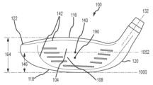
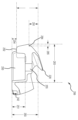
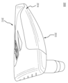
도 1a는 페어웨이 유형 골프 클럽 헤드의 측면도를 예시한다.
도 1b는 페어웨이 유형 골프 클럽 헤드의 정면도를 예시한다.
도 1c는 지면이 표시된 페어웨이 유형 골프 클럽 헤드의 측면도를 예시한다.
도 2a는 페어웨이 유형 골프 클럽 헤드 본체의 부분 절단 평면도를 예시한다.
도 2b는 페어웨이 유형 골프 클럽 헤드 본체의 솔 도면을 예시한다.
도 2c는 페어웨이 유형 골프 클럽 헤드 후방 중량 지지 구조체의 측면도를 예시한다.
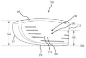
도 3a는 페어웨이 유형 골프 클럽 헤드 페이스 컵의 정면도를 예시한다.
도 3b는 페어웨이 유형 골프 클럽 헤드 페이스 컵의 평면도를 예시한다.
도 3c는 페어웨이 유형 골프 클럽 헤드 페이스 컵 및 가변 타격 페이스의 단면도를 예시한다.
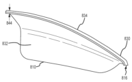
도 4a는 페어웨이 유형 골프 클럽 헤드 크라운 인서트 및 랩 어라운드 섹션의 단면도를 예시한다.
도 4b는 페어웨이 유형 골프 클럽 헤드 크라운 인서트의 평면도를 예시한다.
도 4c는 페어웨이 유형 골프 클럽 헤드 크라운 인서트의 배면도를 예시한다.
도 5a는 크라운 인서트와 솔 인서트를 갖는 페어웨이 유형 골프 클럽 헤드의 측면도를 예시한다.
도 5b는 크라운 인서트와 솔 인서트를 갖는 페어웨이 유형 골프 클럽 헤드의 측면도를 예시한다.
도 5c는 크라운 인서트와 솔 인서트를 갖는 페어웨이 유형 골프 클럽 헤드의 측면도를 예시한다.
도 5d는 크라운 인서트와 솔 인서트를 갖는 페어웨이 유형 골프 클럽 헤드의 측면도를 예시한다.
도 5e는 페어웨이 유형 골프 클럽 헤드의 정면도를 예시한다.
도 5f는 크라운 인서트와 솔 인서트를 갖는 페어웨이 유형 골프 클럽 헤드의 단면도를 예시한다.
도 6a는 페어웨이 유형 골프 클럽 헤드 후방 추의 단면도를 예시한다.
도 6b는 페어웨이 유형 골프 클럽 헤드 후방 추의 단면도를 예시한다.
도 7a는 구멍을 갖는 페어웨이 유형 골프 클럽 헤드 솔 인서트의 평면도를 예시한다.
도 7b는 구멍을 갖는 페어웨이 유형 골프 클럽 헤드 솔 인서트의 저면도를 예시한다.
도 7c는 가변 두께를 갖는 페어웨이 유형 골프 클럽 헤드 솔 인서트의 정면도를 예시한다.
도 8a는 크라운 인서트와 솔 인서트를 갖는 페어웨이 유형 골프 클럽 헤드의 측면도를 예시한다.
도 8b는 크라운 인서트와 솔 인서트를 갖는 페어웨이 유형 골프 클럽 헤드의 측면도를 예시한다.
도 8c는 클럽 헤드 CG와 솔 인서트 CG가 평행하게 위치하는 페어웨이 유형 골프 클럽 헤드의 측면도를 예시한다.
도 8d는 크라운 인서트와 솔 인서트를 갖는 페어웨이 유형 골프 클럽 헤드의 측면도를 예시한다.
도 8e는 크라운 인서트와 솔 인서트를 갖는 페어웨이 유형 골프 클럽 헤드의 측면도를 예시한다.
도 9a는 구멍을 갖는 페어웨이 유형 골프 클럽 헤드 솔 인서트의 저면도를 예시한다.
도 9b는 구멍을 갖는 페어웨이 유형 골프 클럽 헤드 솔 인서트의 평면도를 예시한다.
도 9c는 가변 두께를 갖는 페어웨이 유형 골프 클럽 헤드 솔 인서트의 정면도를 예시한다.
도 10a는 솔 인서트용 부착 수단을 갖는 페어웨이 유형 골프 클럽 헤드의 분해도를 예시한다.
도 10b는 페어웨이 유형 골프 클럽 헤드의 측면도를 예시한다. 1A illustrates a side view of a fairway type golf club head.
1B illustrates a front view of a fairway type golf club head.
1C illustrates a side view of a fairway type golf club head with the ground indicated.
2A illustrates a partially cut-away plan view of a fairway type golf club head body.
2B illustrates a sole view of a fairway type golf club head body.
2C illustrates a side view of a fairway type golf club head rear weight bearing structure.
3A illustrates a front view of a fairway type golf club head face cup.
3B illustrates a plan view of a fairway type golf club head face cup.
3C illustrates a cross-sectional view of a fairway type golf club head face cup and variable striking face.
4A illustrates a cross-sectional view of a fairway type golf club head crown insert and wrap around section.
4B illustrates a plan view of a fairway type golf club head crown insert.
4C illustrates a rear view of a fairway type golf club head crown insert.
5A illustrates a side view of a fairway type golf club head having a crown insert and a sole insert.
5B illustrates a side view of a fairway type golf club head having a crown insert and a sole insert.
5C illustrates a side view of a fairway type golf club head having a crown insert and a sole insert.
5D illustrates a side view of a fairway type golf club head having a crown insert and a sole insert.
5E illustrates a front view of a fairway type golf club head.
5F illustrates a cross-sectional view of a fairway type golf club head having a crown insert and a sole insert.
6A illustrates a cross-sectional view of a fairway type golf club head aft weight.
6B illustrates a cross-sectional view of a fairway type golf club head aft weight.
7A illustrates a plan view of a fairway type golf club head sole insert with holes.
7B illustrates a bottom view of a fairway type golf club head sole insert with holes.
7C illustrates a front view of a fairway type golf club head sole insert with variable thickness.
8A illustrates a side view of a fairway type golf club head having a crown insert and a sole insert.
8B illustrates a side view of a fairway type golf club head having a crown insert and a sole insert.
8C illustrates a side view of a fairway type golf club head with club head CG and sole insert CG positioned in parallel.
8D illustrates a side view of a fairway type golf club head having a crown insert and a sole insert.
8E illustrates a side view of a fairway type golf club head having a crown insert and a sole insert.
9A illustrates a bottom view of a fairway type golf club head sole insert with holes.
9B illustrates a top view of a fairway type golf club head sole insert with holes.
9C illustrates a front view of a fairway type golf club head sole insert with variable thickness.
10A illustrates an exploded view of a fairway type golf club head having attachment means for a sole insert.
10B illustrates a side view of a fairway type golf club head.
정의 Justice
페어웨이 유형 골프 클럽 헤드는 본체, 페이스 컵, 크라운 인서트, 솔 인서트, 후방 추, 또는 이들의 임의의 조합을 포함한다. FLIP 축선 상에 낮은 후방 CG를 달성하는 페어웨이 유형 골프 클럽 헤드의 다양한 실시예가 있다. 크라운 인서트와 본체는, 바람직하게는, 저밀도 재료로 형성되어 추가의 자유 재량 질량이 골프 클럽 헤드 하부 부분에 재분배되도록 한다. 본체 및 페이스 컵이 티타늄 합금과 같은 금속 재료를 포함할 수 있으며, 또는 본체가 섬유 강화 중합체 또는 섬유 강화 합성물과 같은 복합 재료를 포함할 수 있다. 크라운 인서트가 탄소 복합 재료, 섬유 강화 중합체성 재료, 천연 섬유 합성물, 또는 임의의 다른 적합한 저밀도 재료와 같은 복합 재료를 포함할 수 있다. 클럽 헤드가 CG를 솔에 더 가깝게 아래로 구동시키는 대형 고밀도 솔 인서트를 포함할 수 있다. 솔 인서트는 전후 방향으로 포스 라인 상에서 CG 위치의 균형을 맞추는 두꺼운 영역 또는 질량 패드(mass pad)를 포함할 수 있다. 솔 인서트는 클럽 헤드 질량의 많은 부분을 솔 중앙 부분 근처에 할당하여 CG를 향상시킬 수 있다. 솔 인서트는 또한, 본체를 따라 클럽 헤드 둘레를 향해 상방으로 추가로 연장되어 MOI를 향상시킬 수 있다. 클럽 헤드는, CG를 추가로 낮추며 FLIP 축선을 따라 CG의 균형을 맞추기 위해, 1 g 내지 35 g의 질량을 갖는, 제거 가능하거나, 조정 가능하거나, 교환 가능한 후방 추를 추가로 포함할 수 있다. 솔 인서트 및 후방 추는 티타늄 또는 강철과 같은 조밀한 금속 재료를 포함할 수 있다. A fairway type golf club head includes a body, a face cup, a crown insert, a sole insert, a back weight, or any combination thereof. There are various embodiments of fairway type golf club heads that achieve a low aft CG on the FLIP axis. The crown insert and body are preferably formed from a low density material to allow additional freewheeling mass to be redistributed to the lower portion of the golf club head. The body and face cup may include a metallic material such as a titanium alloy, or the body may include a composite material such as a fiber reinforced polymer or fiber reinforced composite. The crown insert may comprise a composite material such as a carbon composite material, a fiber reinforced polymeric material, a natural fiber composite, or any other suitable low density material. The club head may contain a large, high-density sole insert that drives the CG down closer to the sole. The sole insert may include a thick area or mass pad that balances the CG position on the force line in the fore-and-aft direction. Sole inserts can improve CG by allocating much of the club head mass near the center of the sole. The sole insert may also extend further upwards along the body and around the club head to improve MOI. The club head may further include a removable, adjustable or interchangeable rear weight having a mass of 1 g to 35 g to further lower the CG and balance the CG along the FLIP axis. The sole insert and rear weight may include a dense metal material such as titanium or steel.
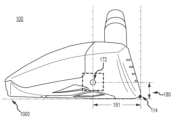
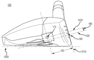
경량 크라운 인서트(800), 본체(202), 고밀도 솔 인서트(430), 제거 가능하거나, 조정 가능하거나, 교환 가능한 후방 추 조립체(1100), 또는 이들의 조합은, 솔 인서트가 없는 클럽 헤드에 비해, 골프공 스핀을 완화하며 감소시키는 낮은 무게 중심을 가진 골프 클럽 헤드를 제공한다. 본원에서 설명되는 페어웨이 유형 골프 클럽 헤드(100)는 고밀도 솔 인서트(430), 경량 크라운 인서트(800), 제거 가능하거나, 조정 가능하거나 교환 가능한 후방 추 조립체(1100), 또는 이들의 조합을 사용하여 FLIP 축선(195)을 따라 CG(172)의 균형을 맞춘다.
I. 일반 용어I. General terms
특징 및 양태가 이하의 상세한 설명 및 첨부 도면을 고려하여 명백해질 것이다. 본 개시의 임의의 실시예를 상세히 설명하기에 앞서, 본 개시의 용례가 이하의 설명에 제시되거나 도면에 도시된 세부 사항이나 구성 및 구성 요소의 배치로 제한되지 않는다는 것을 이해하여야 한다. 본 개시가 다른 실시예를 지원할 수 있으며 다양한 방식으로 실시되거나 수행될 수 있다. 특정 실시예의 설명이 본 개시의 사상 및 범위 내에 있는 모든 변형예, 등가물 및 대안을 포함하는 것으로부터 본 개시를 제한하려는 것이 아니라는 것을 이해하여야 한다. 또한, 본원에 사용된 어법 및 용어는 설명을 위한 것이며 제한적인 것으로 간주되어서는 안된다는 것이 이해될 것이다.Features and aspects will become apparent from consideration of the following detailed description and accompanying drawings. Before describing any embodiment of the present disclosure in detail, it should be understood that the application of the present disclosure is not limited to the details or configurations and arrangements of components shown in the drawings or set forth in the following description. The disclosure is capable of other embodiments and of being practiced or of being carried out in various ways. It should be understood that the description of specific embodiments is not intended to limit the present disclosure from including all modifications, equivalents, and alternatives falling within the spirit and scope of the present disclosure. Also, it will be understood that the phraseology and terminology used herein is for descriptive purposes and should not be regarded as limiting.
설명 및 청구 범위의 용어 "좌측(left)", "우측(right)", "전방(front)", "후방(back)", "상부(top)", "저부(bottom)", "위에(over)", "전방을 향해(forward)", "후방을 향해(rearward)"가 있다면, 이들 용어는 설명의 목적으로 사용된 것으로서, 반드시 영구적인 상대 위치를 설명하기 위한 것은 아니다. 본원에 설명된 장치, 방법, 및/또는 제조품의 실시예가, 예를 들어, 본원에 예시되거나 달리 설명된 바와 다른 배향으로 작동할 수 있도록 이렇게 사용된 용어가 적절한 환경 하에서 상호 호환 가능하다는 것을 이해하여야 한다. 일관성과 명료성을 위해, 본원에 사용된 모든 방향 참조는 참조된 페어웨이 유형 골프 클럽 헤드가, 헤드에 대한 사전 정의된 로프트각 및 라이각이 달성되도록, 수평 방향으로 평평한 지면에 놓혀 있는 것으로 가정한다. 페어웨이 유형 골프 클럽 헤드의 "전방(front)" 또는 "전방을 향한 부분(forward portion)"은 일반적으로 골프 클럽 타격 페이스를 포함하는 페어웨이 유형 골프 클럽 헤드의 측면(지면에 수직으로 볼 때)을 지칭한다. 반대로, 클럽 헤드의 후방 부분은 타격 페이스 후방의 모든 부분 및/또는 임팩트 시에 타격 페이스를 추종하는 클럽의 부분을 포함할 수 있다. The terms "left", "right", "front", "back", "top", "bottom", "above" in the description and claims Wherever "over", "forward", and "rearward" are used, these terms are used for descriptive purposes and are not necessarily intended to describe a permanent relative position. It should be understood that the terms so used are interchangeable under appropriate circumstances so that embodiments of the devices, methods, and/or articles of manufacture described herein may, for example, operate in orientations other than those illustrated or otherwise described herein. do. For consistency and clarity, all directional references used herein assume that the fairway type golf club head referred to is lying on flat ground in a horizontal orientation such that the predefined loft and lie angles for the head are achieved. The “front” or “forward portion” of a fairway type golf club head generally refers to the side (as viewed perpendicular to the ground) of a fairway type golf club head that includes the golf club striking face. do. Conversely, the rear portion of the club head may include any portion behind the striking face and/or the portion of the club that follows the striking face at impact.
단수 표현, "상기", "적어도 하나(at least one)" 및 "하나 이상(one or more)"이 항목 중 적어도 하나가 존재한다는 것을 나타내기 위해 상호 호환적으로 사용되며; 문맥상 달리 명확하게 나타내지 않는 한 복수의 이러한 항목이 존재할 수 있다. 첨부된 청구 범위를 포함하여 본 명세서의 매개 변수(예를 들어, 양 또는 조건)의 모든 수치 값은, 용어 "약(about)"이 실제로 수치 값 앞에 나타나든지 아니든지, 모든 경우에 "약(about)"에 의해 수정되는 것으로서 이해되어야 한다. "약(about)"은 명시된 수치 값이 약간의 부정확성(값의 정확성에 약간 접근하는; 값에 대략 또는 합리적으로 근접하는; 거의)을 허용한다는 것을 나타낸다. "약(about)"에 의해 제공된 부정확성이 이러한 일반적인 의미로 당 업계에서 달리 이해되지 않는 경우, 본원에 사용된 바와 같은, "약(about)"은 이러한 매개 변수를 측정 및 사용하는 일반적인 방법으로부터 발생할 수 있는 변화를 적어도 나타낸다. 또한, 개시 범위가 모든 개시 값 및 전체 범위 이내의 추가로 분할된 범위를 포함한다. 범위 이내의 각각의 값 및 범위의 끝점이 이로써 모두 별개의 실시예로서 개시된다. 용어 "포함하다(comprises)", "포함하는(comprising)", "포함하는(including)" 및 "구비하는(having)"은 포괄적이므로, 명시된 항목의 존재를 명시하지만 다른 항목의 존재를 배제하지는 않는다. 본 명세서에서 사용되는 바와 같은, 용어 "또는(or)"은 나열 항목 중 어느 하나 및 하나 이상의 모든 조합을 포함한다. 다양한 항목을 서로 구별하기 위해 용어 제 1, 제 2, 제 3 등이 사용되는 경우, 이러한 지정은 단지 편의를 위한 것이며 항목을 제한하는 것은 아니다. The singular expressions “the”, “at least one” and “one or more” are used interchangeably to indicate that at least one of the items is present; A plurality of such items may be present unless the context clearly dictates otherwise. All numerical values of a parameter (eg, amount or condition) herein, including in the appended claims, refer to "about" in all instances, whether or not the term "about" actually appears before the numerical value. about)". "About" indicates that the specified numerical value is tolerant of some imprecision (slightly approaching the accuracy of the value; approximately or reasonably close to the value; nearly). Unless otherwise understood in the art in this general sense, the imprecision provided by "about", as used herein, "about" will result from the usual methods of measuring and using these parameters. It indicates at least possible changes. Also, the disclosure range includes all disclosure values and further subdivided ranges within the entire range. Each value within the range and endpoint of the range are all hereby disclosed as a separate example. The terms "comprises", "comprising", "including" and "having" are inclusive, meaning that they specify the presence of specified items but do not exclude the presence of other items. don't As used herein, the term "or" includes any one and all combinations of one or more of the listed items. Where the terms first, second, third, etc. are used to distinguish various items from one another, such designations are for convenience only and do not limit the item.
설명 및 청구범위에서 "제 1", "제 2", "제 3" 등의 용어는 만약 있다면 유사한 요소 사이의 구별을 위해 사용되며 반드시 특정한 순서 또는 연대순을 설명하기 위한 것은 아니다. 본원에 설명된 실시예가, 예를 들어, 본원에 예시되거나 달리 설명된 바와 다른 순서로 작동할 수 있도록 이렇게 사용된 용어가 적절한 환경 하에서 상호 호환 가능하다는 것을 이해하여야 한다. 또한, 용어 "포함하다(include)"와 "구비하다(have)" 및 그 임의의 변형어가 비배타적인 포함의 의미를 갖도록 의도되어, 요소 목록을 포함하는 공정, 방법, 시스템, 물품, 장치, 또는 기기가 이러한 요소로 반드시 제한되는 것이 아니라, 명시적으로 나열되지 않았거나 이러한 공정, 방법, 시스템, 물품, 장치, 기기에 수반되지 않은 다른 요소를 포함할 수 있다. In the description and claims, the terms “first,” “second,” “third,” and the like are used to distinguish between like elements, if any, and are not necessarily intended to describe a particular order or chronological order. It is to be understood that the terms so used are interchangeable under appropriate circumstances so that the embodiments described herein may, for example, operate in an order different from that illustrated or otherwise described herein. Also, the terms "include" and "have" and any variations thereof are intended to have a meaning of non-exclusive inclusion, such that a process, method, system, article, device, Alternatively, the device is not necessarily limited to these elements, but may include other elements not expressly listed or involved in such process, method, system, article, device, or device.
II. 페어웨이 유형 클럽 헤드II. fairway type club head
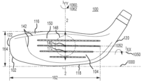
본원에 정의된 바와 같은, "페어웨이 유형 골프 클럽 헤드"는 특정 치수 범위에 의해 정의될 수 있는 특정 로프트, 부피, 및 치수를 갖는 클럽 헤드이다. 특히, 본원에 개시된 본 발명과 관련하여 설명된 바와 같은 페어웨이 유형 클럽 헤드는 아래에 정의된 범위 이내의 로프트각, 부피, 길이, 깊이, 높이 및 페이스 높이를 포함한다. 아래에 지정된 범위는 페어웨이 유형 골프 클럽 헤드를 페어웨이 유형 클럽 헤드로만 제한한다. 다시 말해, 페어웨이 유형 골프 클럽 헤드는 드라이버 유형, 하이브리드 유형, 아이언 유형, 또는 퍼터 유형 골프 클럽 헤드일 수 없다. 본원에 정의되고 아래에서 사용되는 바와 같은, 페어웨이 유형 골프 클럽 헤드는 본체, 페이스 컵, 크라운 인서트, 솔 인서트, 및 후방 추로 구성된 그룹으로부터 선택된 특징을 포함한다. 도 1a 및 도 1b는 몸체(102) 및 타격 페이스(104)를 갖는 페어웨이 유형 골프 클럽 헤드(100)를 예시한다. 클럽 헤드(100)의 몸체(102)가 전방 단부(108), 전방 단부(108) 반대측의 후방 단부(110), 크라운(116), 크라운(116) 반대측의 솔(118), 힐(120), 및 힐(120) 반대측의 토우(122)를 포함한다. 몸체(102)가 크라운(116)과 솔(118)의 사이에 인접하여 위치한 스커트 또는 후단 가장자리(128)를 추가로 포함하며, 스커트는 클럽 헤드(100)의 힐(120) 근처로부터 토우(122) 근처까지 연결된다. As defined herein, a “fairway type golf club head” is a club head having a specific loft, volume, and dimension that can be defined by a specific range of dimensions. In particular, fairway type club heads as described in connection with the inventions disclosed herein include a loft angle, volume, length, depth, height and face height within the ranges defined below. The ranges specified below limit fairway type golf club heads to fairway type club heads only. In other words, a fairway type golf club head cannot be a driver type, hybrid type, iron type, or putter type golf club head. As defined herein and used below, a fairway type golf club head includes features selected from the group consisting of a body, a face cup, a crown insert, a sole insert, and a back weight. 1A and 1B illustrate a fairway type
본원에 정의된 바와 같은, 페어웨이 유형 클럽 헤드의 로프트각은 대략 35도 미만, 대략 34도 미만, 대략 33도 미만, 대략 32도 미만, 대략 31도 미만, 또는 대략 30도 미만이다. 일부 실시예에서는, 페어웨이 유형 골프 클럽 헤드의 로프트각이 대략 12도를 초과, 대략 13도를 초과, 대략 14도를 초과, 대략 15도를 초과, 대략 16도를 초과, 대략 17도를 초과, 대략 18도를 초과, 대략 19를 초과, 또는 대략 20도를 초과할 수 있다. 예를 들어, 일부 실시예에서는, 페어웨이 유형 골프 클럽 헤드의 로프트각이 14도 내지 35도, 15도 내지 35도, 20도 내지 35도, 또는 12도 내지 30도일 수 있다. As defined herein, a fairway type club head has a loft angle of less than about 35 degrees, less than about 34 degrees, less than about 33 degrees, less than about 32 degrees, less than about 31 degrees, or less than about 30 degrees. In some embodiments, a fairway type golf club head has a loft angle greater than about 12 degrees, greater than about 13 degrees, greater than about 14 degrees, greater than about 15 degrees, greater than about 16 degrees, greater than about 17 degrees, It may be greater than about 18 degrees, greater than about 19 degrees, or greater than about 20 degrees. For example, in some embodiments, a fairway type golf club head may have a loft angle of 14 to 35 degrees, 15 to 35 degrees, 20 to 35 degrees, or 12 to 30 degrees.
본원에 설명된 바와 같은, 페어웨이 유형 클럽의 "부피"가 대략 170 cm3 미만, 대략 180 cm3 미만, 대략 190 cm3 미만, 또는 대략 200 cm3 미만일 수 있다. 그러나, 페어웨이 유형 클럽의 부피가 160 cm3 미만일 수는 없다. 일부 실시예에서, 페어웨이 유형 클럽 헤드의 부피가 대략 150 cm3 내지 200 cm3, 대략 160 cm3 내지 170 cm3, 대략 160 cm3 내지 180 cm3, 또는 대략 170 cm3 내지 190 cm3일 수 있다. 페어웨이 유형 클럽의 부피가 200 cm3를 초과할 수 없다. 예시적인 일 실시예에서, 페어웨이 유형 클럽의 부피가 169 cm3이다. As described herein, a fairway type club may have a “volume” of less than about 170 cm 3 , less than about 180 cm 3 , less than about 190 cm 3 , or less than about 200 cm 3 . However, fairway type clubs cannot have a volume less than 160 cm 3 . In some embodiments, a fairway type club head may have a volume between approximately 150 cm 3 and 200 cm 3 , between approximately 160 cm 3 and 170 cm 3 , between approximately 160 cm 3 and 180 cm 3 , or between approximately 170 cm 3 and 190 cm 3 . there is. Fairway type clubs cannot exceed 200 cm 3 in volume. In one exemplary embodiment, the volume of a fairway type club is 169 cm 3 .
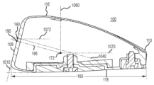
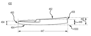
본원에 설명된 바와 같은, 페어웨이 유형 골프 클럽 헤드의 "페어웨이 유형 클럽 헤드 깊이"(160)는 페어웨이 유형 골프 클럽 헤드의 전후 치수로서 정의될 수 있다. 도 5f를 참조하면, 페어웨이 유형 클럽 헤드의 깊이(160)가 Z-축선(1072)에 평행한 방향으로 전방 단부(108)로부터 후방 단부(110)까지의 클럽 헤드의 가장 먼 범위로서 측정된다. 깊이(160)가 3.00 인치 내지 4.00 인치의 범위에 있을 수 있다. 일부 실시예에서는, 깊이(160)가 3.00 인치 내지 3.40 인치, 3.25 인치 내지 3.40 인치, 3.30 인치 내지 3.50 인치, 또는 3.50 인치 내지 4.00 인치의 범위에 있을 수 있다. 깊이(160)는 4.00 인치를 초과할 수 없다. 예시적인 일 실시예에서, 깊이(160)가 3.363 인치이다. As described herein, “fairway type club head depth” 160 of a fairway type golf club head may be defined as the fore-to-aft measurement of the fairway type golf club head. Referring to FIG. 5F , the
본원에 설명된 바와 같은, 페어웨이 유형 골프 클럽 헤드의 "페어웨이 유형 클럽 헤드 높이"(164)는 페어웨이 유형 골프 클럽 헤드의 크라운-솔 치수로서 정의될 수 있다. 도 5e를 참조하면, 페어웨이 유형 골프 클럽 헤드(100)의 높이가, 정면도에서 볼 때, Y-축선(1062)에 평행한 방향으로 크라운(116)으로부터 솔(118)까지의 페어웨이 유형 골프 클럽 헤드(100)의 가장 먼 범위로서 측정될 수 있다. 많은 실시예에서, 클럽 헤드(100)의 높이(164)가 미국 골프 협회(USGA)와 같은 골프 관리체에 따라 측정될 수 있다. 예를 들어, 클럽 헤드(100)의 높이(164)가 USGA의 우드 클럽의 클럽 헤드 크기를 측정하기 위한 절차(USGA-TPX3003, Rev. 1.0.0, 2003년 11월 21일)(https://www.usga.org/content/dam/usga/pdf/Equipment/TPX3003-procedure-for-measuring-theclub- head-size-of-wood-clubs.pdf에서 이용 가능)("우드 클럽의 클럽 헤드 크기 측정을 위한 절차")에 따라 결정될 수 있다. 높이(164)가 1.25 인치 내지 2.00 인치의 범위에 있을 수 있다. 일부 실시예에서는, 높이(164)가 1.25 인치 내지 1.50 인치, 1.30 인치 내지 1.50 인치, 1.35 인치 내지 1.75 인치, 1.45 인치 내지 1.80 인치, 또는 1.50 인치 내지 2.00 인치일 수 있다. 예시적인 일 실시예에서, 클럽 헤드 높이(164)가 1.424 인치이다. 높이(164)는 2.00 인치를 초과하지 않는다. As described herein, the “fairway type club head height” 164 of a fairway type golf club head may be defined as the crown-to-sole dimension of the fairway type golf club head. Referring to FIG. 5E , the height of a fairway type
본원에 설명된 바와 같은, 페어웨이 유형 골프 클럽 헤드의 "페어웨이 유형 클럽 헤드 길이"(162)는 페어웨이 유형 골프 클럽 헤드의 힐-토우 치수로서 정의될 수 있다. 도 5e를 참조하면, 페어웨이 유형 골프 클럽 헤드(100)의 길이(162)가, 정면도에서 볼 때, X-축선(1052)에 평행한 방향으로 힐(120)로부터 토우(122)까지의 클럽 헤드(100)의 가장 먼 범위로서 측정될 수 있다. 많은 실시예에서, 클럽 헤드(100)의 길이(162)가 미국 골프 협회(USGA)와 같은 골프 관리체에 따라 측정될 수 있다. 예를 들어, 클럽 헤드(100)의 길이(162)가 USGA의 우드 클럽의 클럽 헤드 크기를 측정하기 위한 절차(USGA-TPX3003, Rev. 1.0.0, 2003년 11월 21일)(https://www.usga.org/content/dam/usga/pdf/Equipment/TPX3003-procedure-for-measuring-theclub- head-size-of-wood-clubs.pdf에서 이용 가능)("우드 클럽의 클럽 헤드 크기 측정을 위한 절차")에 따라 결정될 수 있다. 길이(162)가 3.00 인치 내지 4.60 인치의 범위에 있을 수 있다. 일부 실시예에서는, 길이(162)가 3.00 인치 내지 4.00 인치 내지 4.40 인치, 4.25 인치 내지 4.40 인치, 또는 4.30 인치 내지 4.60 인치일 수 있다. 길이는 4.60 인치를 초과하지 않는다. 예시적인 일 실시예에서, 길이(162)가 4.384 인치이다. As described herein, the “fairway type club head length” 162 of a fairway type golf club head may be defined as the heel-to-toe dimension of the fairway type golf club head. Referring to FIG. 5E , the
본원에 설명된 바와 같은, 페어웨이 유형 골프 클럽 헤드의 "페어웨이 유형 페이스 높이"(144)가 크라운(116) 근처의 타격 페이스 둘레(142)의 상단부와 솔(118) 근처의 타격 페이스 둘레(142)의 하단부 사이의 로프트 평면(1010)에 평행하게 측정된 높이로서 정의될 수 있다(도 3a 참조). 이들 실시예에서, 타격 페이스 둘레(142)는, 곡률이 타격 페이스(104)의 벌지(bulge) 및/또는 롤(roll)로부터 벗어나는, 타격 페이스(104)의 외부 가장자리를 따라 위치할 수 있다. 페이스 높이(144)가 1.00 인치 내지 1.50 인치의 범위일 수 있다. 일부 실시예에서, 페이스 높이(144)가 1.00 인치 내지 1.25 인치, 1.00 인치 내지 1.15 인치, 1.15 인치 내지 1.35 인치, 또는 1.15 인치 내지 1.50 인치일 수 있다. 예시적인 일 실시예에서, 페이스 높이(144)가 1.110 인치이다. As described herein, the "fairway type face height" 144 of a fairway type golf club head is defined as the upper end of the
본원에 설명된 바와 같은, 페어웨이 유형 골프 클럽 헤드의 "기하학적 중심"(140)은 타격 페이스 둘레(142)의 기하학적 중심 지점이다. 또 다른 접근법으로서, 타격 페이스(104)의 기하학적 중심이 미국 골프 협회(USGA)와 같은 골프 관리체의 정의에 따라 위치할 수 있다. 예를 들어, 타격 페이스의 기하학적 중심이 USGA의 골프 클럽 헤드의 유연성 측정을 위한 절차(USGA-TPX3004, Rev. 1.0.0, 2008년 5월 1일)의 섹션 6.1에 따라 결정될 수 있다(http://www.usga.org/equipment/testing/protocols/Procedure-For-Measuring-The-Flexibility-Of-A-Golf-Club-Head/에서 이용 가능)("유연성 절차").As described herein, the "geometric center" 140 of a fairway type golf club head is the geometric center point around the
본원에 설명된 바와 같은, 페어웨이 유형 골프 클럽 헤드의 "기하학적 중심 높이"(146)는 지면(1000)으로부터 페어웨이 유형 클럽 헤드의 기하학적 중심까지 수직으로 측정된 높이이다. 기하학적 중심 높이(146)가 0.40 인치 내지 0.75 인치의 범위일 수 있다. 예를 들어, 기하학적 중심 높이(146)가 0.40 인치 내지 0.60 인치, 0.50 인치 내지 0.70 인치, 또는 0.65 인치 내지 0.75 인치일 수 있다. 예시적인 일 실시예에서, 기하학적 중심 높이(146)가 0.661 인치이다. As described herein, the "geometric center height" 146 of a fairway type golf club head is the height measured vertically from the
본원에 설명된 바와 같은, 페어웨이 유형 골프 클럽 헤드의 "전단 가장자리(leading edge)"(114)가 타격 페이스 둘레(142)의 가장 솔 방향 부분으로서 식별될 수 있다. 예를 들어, 페어웨이 유형 골프 클럽 헤드 전단 가장자리(114)는 타격 페이스의 롤 및 벌지로부터 페어웨이 유형 골프 클럽 헤드의 솔로의 전이부이다. As described herein, the “leading edge” 114 of a fairway type golf club head may be identified as the most sole-direction portion of the
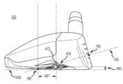
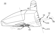
본원에 정의되고 아래에서 사용되는 바와 같은, 페어웨이 유형 골프 클럽 헤드의 "포스 라인 임팩트 지점"(또는 FLIP)(190)은 페어웨이 유형 골프 클럽 타격력이 골프공으로 가장 효율적으로 전달되는 지점인 타격 페이스(104) 상의 지점이다. As defined herein and used below, the "force line point of impact" (or FLIP) 190 of a fairway type golf club head is the
본원에 설명된 바와 같은, 페어웨이 유형 골프 클럽 헤드의 "FLIP 높이"(192)는 지면(1000)으로부터 FLIP(190)까지 수직으로 측정된 높이이다. FLIP 높이(192)는 0.55 인치 내지 0.75 인치의 범위 이내이다. FLIP 높이(192)가 대략 0.55 인치, 대략 0.56 인치, 대략 0.57 인치, 대략 0.58 인치, 대략 0.59 인치, 대략 0.60 인치, 대략 0.61 인치, 대략 0.62 인치, 대략 0.63 인치, 대략 0.64 인치, 대략 0.65 인치, 대략 0.66 인치, 대략 0.67 인치, 대략 0.68 인치, 대략 0.69 인치, 대략 0.70 인치, 대략 0.71 인치, 대략 0.72 인치, 대략 0.73 인치, 대략 0.74 인치, 또는 대략 0.75 인치일 수 있다. As described herein, the “FLIP height” 192 of a fairway type golf club head is the height measured vertically from the
본원에 정의되고 아래에서 사용되는 바와 같은, 페어웨이 유형 골프 클럽 헤드의 "포스 라인 임팩트 지점 축선"(또는 FLIP 축선)(195)은 FLIP(190)에서 시작하여 타격 페이스(104)로부터 후방으로 연장되며 FLIP(190)에서 타격 페이스(104)에 수직인 축선이다. As defined herein and used below, the “force line impact point axis” (or FLIP axis) 195 of a fairway type golf club head begins at
본원에 정의된 바와 같은, 페어웨이 유형 골프 클럽 헤드의 "둘레"(112)는 클럽 헤드 상부 부분(152)으로부터 클럽 헤드 하부 부분(156)으로의 전이부를 포함한다. 둘레(112)는, 페어웨이 유형 골프 클럽 헤드(100)가 어드레스 위치에 있을 때 지면(1000)에 수직으로 그려진 선에 대한 접선을 각각 갖는, 골프 클럽 헤드 주위의 일련의 지점에 의해 정의된다. 페어웨이 유형 골프 클럽 헤드(100)의 둘레는 이들 모든 지점의 합이다. 페어웨이 유형 골프 클럽 헤드(100)의 상부 부분(152)은 페어웨이 유형 골프 클럽 헤드 둘레 위의, 타격 페이스(104)를 제외한, 페어웨이 유형 골프 클럽 헤드(100)의 해당 부분으로서 정의된다. 페어웨이 유형 골프 클럽 헤드(100)의 하부 부분(156)은 페어웨이 유형 골프 클럽 헤드 둘레 아래의, 타격 페이스(104)를 제외한, 페어웨이 유형 골프 클럽 헤드(100)의 해당 부분으로서 정의된다.As defined herein, the “perimeter” 112 of a fairway type golf club head includes the transition from the upper
본원에 정의되고 아래에서 사용되는 바와 같은, 페어웨이 유형 골프 클럽 헤드의 "본체"(202)는 크라운 인서트, 페이스 컵, 솔 인서트, 및 후방 추가 부착되어 페어웨이 유형 골프 클럽 헤드(100)를 형성하는 기계적 부착 구조를 제공한다. 도 2a 내지 도 2c를 참조하면, 페어웨이 유형 골프 클럽 헤드 본체(202)는 본체 전방 부분(214), 본체 후방 부분(212), 본체 토우 부분(222), 본체 힐 부분(220), 및 솔(218), 및 크라운 리턴(216)를 포함한다. 본원에 정의되고 아래에서 사용되는 바와 같은, 본체 힐 부분(220)은 힐 리턴(224), 힐 타격 페이스 부분(226), 및 호젤(230)을 포함한다. 본원에 정의되고 아래에서 사용되는 바와 같은, 본체 전방 부분(214)은 전방 구멍(210), 본체 토우 부분(222), 힐 리턴(224), 힐 타격 페이스 부분(226), 솔(218), 및 크라운 리턴(216)를 포함한다. As defined herein and used below, the "body" 202 of a fairway type golf club head is a mechanical to which a crown insert, face cup, sole insert, and back weight are attached to form fairway type
본원에 정의되고 아래에서 사용되는 바와 같은, 페어웨이 유형 골프 클럽 헤드의 "솔(sole)"(218)은 본체의 하부의 지면 방향 대향 부분이며, 솔 외부 표면(219), 솔 토우방향 부분(211), 솔 힐방향 부분(215), 및 솔 중앙 부분(221)을 포함한다. 솔(218)은 솔 인서트 홈(240)을 포함한다. 솔(218)은 후방 추 홈(250)을 추가로 포함한다. 솔 중앙 부분(221)은 일반적으로, 힐-토우 방향으로 지면(1000)에 평행하다. 솔 토우방향 부분(211)은 솔 중앙 부분(221)으로부터 크라운 방향으로 상방으로 만곡된다. 솔 힐방향 부분(215)은 솔 중앙 부분(221)으로부터 크라운 방향으로 상방으로 만곡된다. As defined herein and used below, the “sole” 218 of a fairway type golf club head is the lower, ground facing portion of the body, the sole
본원에 정의되고 아래에서 사용되는 바와 같은, 페어웨이 유형 골프 클럽 헤드의 "솔 인서트 홈(sole insert recess)"(240)은 솔 외부 표면(219)으로부터 내측으로 최외측 표면을 갖는 만입부이다. 솔 인서트 홈(240)은 그 범위의 대부분이 솔 중앙 부분(221)의 내부에 있다. 솔 인서트 홈(240)은 솔 인서트 홈 바닥(241), 솔 인서트 체결구 홈(243), 솔 인서트 체결구 구멍(247), 및 솔 인서트 전방을 향한 질량 패드 홈(248)을 추가로 포함한다. 질량 패드 홈(248)이 솔 인서트 홈(240)의 상이한 개소에 위치할 수 있다. 솔 인서트는 솔 외부 표면(219)으로부터 내측으로 측정된 솔 인서트 홈 바닥 깊이(242)를 포함한다. 솔 인서트의 전방을 향한 질량 패드 홈(248)은 솔 인서트 홈 바닥(241)으로부터 내측으로 측정된 전방을 향한 질량 패드 홈 깊이(249)(도시하지 않음)를 추가로 포함한다. 질량 패드 홈 깊이(249)가 솔 인서트 두께(448)에 해당한다. 솔(218)은 샤프트 부착 홈(290) 및 샤프트 체결구 구멍(292)을 추가로 포함한다. As defined herein and used below, a “sole insert recess” 240 of a fairway type golf club head is a depression having an outermost surface inward from the sole
본원에 정의되고 아래에서 사용되는 바와 같은, 페어웨이 유형 골프 클럽 헤드의 "솔 후방 추 홈(sole rear weight recess)"(250)은, 인접한 솔 외부 표면(219)으로부터 내측으로 측정된 솔 후방 추 홈 깊이(251)를 갖는, 후방 추를 수용하도록 구성된 솔(218)의 후방 부분의 내측으로의 만입부이다. 솔 후방 추 홈(250)은, 추 홈 깊이(251)보다 작은 인접한 솔 외부 표면(219)으로부터 내측으로 측정된 레지 깊이(254)를 갖는, 추 홈 후방 레지(ledge)(252)를 포함한다. 후방 추 홈(250)은 후방 추 체결구 구멍(255)을 포함한다. As defined herein and used below, a “sole rear weight recess” 250 of a fairway type golf club head is a sole rear weight recess measured inwardly from an adjacent sole
본원에 정의되고 아래에서 사용되는 바와 같은 페어웨이 유형 골프 클럽 헤드의 "솔 인서트"(430)는 솔 인서트 홈(250) 내부에 수용되도록 구성된 고밀도 인서트이다. 도 7a를 참조하면, 솔 인서트(430)는, 전방 가장자리(454), 후방 가장자리(456), 힐측 가장자리(458), 토우측 가장자리(460), 상면(462) 및 저면(464)을 갖는, 둘레(420)를 포함한다. 솔 인서트(430)는 상면(462)이 솔 인서트 홈 바닥(241)과 접촉하며 저면(464)이 솔 외부 표면(219)의 일부를 형성하도록 솔 인서트 홈(240) 내부에 수용되도록 구성된다. 솔 인서트(430)는 솔 외부 표면(219)의 실질적인 부분을 획정하도록 비교적 클 수 있다. 솔 인서트 둘레(420)는 길이, 폭 및 두께와 같은 솔 인서트(430)의 치수를 정의하는 데 사용된다. A “sole insert” 430 of a fairway type golf club head, as defined herein and used below, is a high-density insert configured to be received within a
본원에 정의되고 아래에서 사용되는 바와 같은, 페어웨이 유형 골프 클럽 헤드의 "솔 인서트 깊이"(446)는 솔 인서트를 가로질러 전후 방향 전방 가장자리(454)로부터 후방 가장자리(456)까지 측정된다(도 7b 참조). 솔 인서트 깊이(446)는 힐-토우 방향으로 솔 인서트(430)를 가로질러 균일할 수 있다. 대안으로서, 깊이(446)가 힐-토우 방향으로 솔 인서트(430)를 가로질러 변할 수 있다. 솔 인서트 깊이(446)가 0.5 인치 내지 2.00 인치의 범위일 수 있다. 깊이(446)가 1.3 인치를 초과, 1.4 인치를 초과, 1.5 인치를 초과, 1.6 인치를 초과, 1.7 인치를 초과, 또는 1.8 인치를 초과할 수 있다. 대안으로서, 깊이(446)가 0.5 인치 내지 2.0 인치, 0.6 인치 내지 1.8 인치, 1.3 인치 내지 1.6 인치, 1.5 인치 내지 1.8 인치, 1.7 인치 내지 1.8 인치, 또는 1.7 인치 내지 2.0 인치의 범위일 수 있다. 예시적인 일 실시예에서, 최대 깊이(446)가 1.76 인치이다. 솔 인서트 깊이(446)는, 본체 솔(218)의 풋프린트(footprint)의 내부에 남아 있으면서, 솔(118) 근처에 큰 질량을 제공하여 CG를 낮추도록 선택된다. As defined herein and used below, “sole insert depth” 446 of a fairway type golf club head is measured across the sole insert from front-to-back front edge 454 to trailing edge 456 ( FIG. 7B ). reference).
본원에 정의되고 아래에서 사용되는 바와 같은, 페어웨이 유형 골프 클럽 헤드의 "솔 인서트 길이"(447)는 솔 인서트 힐측 가장자리(458)로부터 솔 인서트 토우측 가장자리(460)까지 측정된다(도 7b 참조). 솔 인서트 깊이(447)가 전후 방향으로 솔 인서트(430)를 가로질러 균일할 수 있다. 대안으로서, 길이(447)가 전후 방향으로 솔 인서트(430)를 가로질러 변할 수 있다. 솔 인서트 길이(447)가 1.00 인치 내지 4.00 인치의 범위일 수 있다. 길이(447)가 2.2 인치를 초과, 2.3 인치를 초과, 2.4 인치를 초과, 2.5 인치를 초과, 2.6 인치를 초과, 또는 2.7 인치를 초과할 수 있다. 대안으로서, 길이(447)가 1.0 인치 내지 2.6 인치, 2.2 인치 내지 2.6 인치, 2.4 인치 내지 2.7 인치, 2.5 인치 내지 2.8 인치, 또는 2.7 인치 내지 3.0 인치의 범위일 수 있다. 예시적인 일 실시예에서, 최대 길이(447)가 2.54 인치이다. As defined herein and used below, the “sole insert length” 447 of a fairway type golf club head is measured from the sole
본원에 정의되고 아래에서 사용되는 바와 같은, 페어웨이 유형 골프 클럽 헤드의 "솔 인서트 두께"(448)는 솔 인서트 상면(462)으로부터 솔 인서트 저면(464)까지 측정된다(도 7c 참조). 솔 인서트(430)는 클럽 헤드 CG(172)의 균형을 맞추기 위해 상이한 부분에 걸쳐 얇아지거나 두꺼워질 수 있다. 두께(448)가 솔 인서트(430)를 가로질러 전후 방향 및/또는 힐-토우 방향으로 변할 수 있다. 대안으로서, 솔 인서트 두께(448)가 솔 인서트(430)를 가로질러 전후 방향 및/또는 힐-토우 방향으로 균일할 수 있다. 솔 인서트 두께(448)가 0.050 인치 내지 0.30 인치의 범위일 수 있다. 두께(448)가 0.050 인치를 초과, 0.055 인치를 초과, 0.060 인치를 초과, 0.065 인치를 초과, 0.070 인치를 초과, 0.075 인치를 초과, 0.080 인치를 초과, 0.085 인치를 초과, 0.090 인치를 초과, 0.095 인치를 초과, 0.10 인치를 초과, 0.11 인치를 초과, 0.12 인치를 초과, 0.13 인치를 초과, 0.14 인치를 초과, 0.15 인치를 초과, 0.16 인치를 초과, 0.17 인치를 초과, 0.18 인치를 초과, 0.19 인치를 초과, 0.20 인치를 초과, 0.21 인치를 초과, 0.22 인치를 초과, 0.23 인치를 초과, 0.24 인치를 초과, 0.25 인치를 초과, 0.26 인치를 초과, 0.27 인치를 초과, 0.28 인치를 초과, 0.29 인치를 초과, 또는 0.30 인치를 초과할 수 있다. 대안으로서, 두께(448)가 0.050 인치 내지 0.10 인치, 0.075 인치 내지 0.20 인치, 또는 0.075 인치 내지 0.20 인치일 수 있다. 솔 인서트 두께(448)는, 클럽 헤드 CG(172)를 전후 방향 및 힐-토우 방향으로 균형을 맞추면서, 솔(118) 근처에 실질적인 질량을 제공하도록 선택된다. As defined herein and used below, the “sole insert thickness” 448 of a fairway type golf club head is measured from sole insert
본원에 정의되고 아래에서 사용되는 바와 같은, 페어웨이 유형 골프 클럽 헤드의 "크라운 구멍"(234)은 본체 토우 부분(222), 본체 힐 부분(220), 솔(218), 크라운 리턴(216) 및 본체 후방 부분(212)에 의해 둘러싸여 획정된 상부의 상측 개구를 포함한다. 크라운 구멍(234)은 토우 만입부(260) 및 힐 만입부(262)를 포함하며, 여기서 토우 만입부(260) 및 힐 만입부(262)는 각각, 페어웨이 유형 골프 클럽 헤드(100)의 상부 부분으로부터 페어웨이 유형 골프클럽 헤드(100)의 하부 부분을 향해 전이부를 지나쳐 크라운 구멍(234)에서 연장된다. 크라운 구멍 둘레는 크라운 플랜지(217), 후방 플랜지(228), 토우 크라운 구멍 토우 만입부 플랜지(261), 및 크라운 구멍 힐 만입부 플랜지(263)를 추가로 포함한다. 크라운 플랜지(217)는 크라운 리턴(216)로부터 내측으로 오목하게 형성되며, 상방으로 배향된 외부 표면을 갖는다. 후방 플랜지(228)는 본체 후방 부분 후방 가장자리(213)로부터 내측으로 오목하게 형성되며, 후방을 향하여 상방으로 배향된 외부 표면을 갖는다. 토우 만입부 플랜지(261)는 토우 부분(222)의 외부 표면 및 솔(218)의 외부 표면으로부터 내측으로 오목하게 형성된다. 토우 만입부 플랜지(261)의 외부 표면이 토우 방향 및 하방으로 배향된다. 힐 만입부 플랜지(263)는 힐 부분(220)과 솔(218)로부터 내측으로 오목하게 형성된다. 힐 만입부 플랜지(263)의 외부 표면이 힐 방향으로 하방으로 배향된다. 크라운 플랜지(217), 후방 플랜지(228), 토우 만입부 플랜지(261) 및 힐 만입부 플랜지(263)의 외부 표면은 복수의 플랜지 스페이서(270)를 추가로 포함한다. 플랜지 스페이서(270)는, 크라운 인서트(800)가 크라운 구멍(234)에 접착식으로 부착될 때 간극을 제공하기 위해, 각각의 플랜지의 외부 표면으로부터 외측으로 연장된다. As defined herein and used below, the “crown hole” 234 of a fairway type golf club head comprises a
본원에 정의되고 아래에서 사용되는 바와 같은, 페어웨이 유형 골프 클럽 헤드의 "조인트 깊이(joint depth)"는 본체(202) 최외측 표면으로부터 크라운 플랜지(217), 후방 플랜지(228), 토우 플랜지(261) 및 힐 플랜지(263)가 내측으로 오목하게 형성되는 거리이다. 조인트 깊이는 본체(202)의 외부 표면으로부터 개개의 플랜지(217, 228, 261, 263)의 외부 표면까지 측정된다. 조인트 깊이가 0.010 인치 내지 0.050 인치의 범위에 있을 수 있다. 일부 실시예에서, 조인트 깊이가 0.010 인치 내지 0.030 인치, 0.020 인치 내지 0.040 인치, 또는 0.025 인치 내지 0.050 인치이다. 예시적인 일 실시예에서, 조인트 깊이가 0.030 인치이다. As defined herein and used below, the “joint depth” of a fairway type golf club head is defined as the distance from the outermost surface of the
본원에서 정의되고 아래에서 사용되는 바와 같은, 페어웨이 유형 골프 클럽 헤드의 "전방 구멍"(210)은 본체 토우 부분(222), 힐 리턴(224), 힐 타격 페이스 부분(226), 솔(218), 및 크라운 리턴(216)에 의해 둘러싸여 획정된 전방을 향한 개구이다. 전방 구멍(210)은 일반적으로, 로프트 평면(1010)에 평행한 전방 구멍 평면(280)을 획정한다. 전면 구멍 평면(280)은 로프트 평면(1010)으로부터 후방으로, 전방 구멍 평면 오프셋 거리(282)만큼, 오프셋된다.As defined herein and used below, the “front hole” 210 of a fairway type golf club head comprises a
본원에 정의되고 아래에서 사용되는 바와 같은, 페어웨이 유형 골프 클럽 헤드의 "후방 추 지지 구조체"(299)는, 페어웨이 유형 골프 클럽 헤드의 가장 멀리 있는 후방을 향한 부분에 위치하며 두꺼워진, 솔 중앙 부분(221)의 일 섹션이다. 도 2a 내지 도 2c를 참조하면, 지지 구조체(299)는 후방 플랜지(228), 후방 추 홈(250), 및 후방 추 홈(250) 주위의 지지 재료를 포함한다. 지지 구조체의 전후 방향으로 측정된 구조체 길이(283)가 1.50 인치 내지 0.75 인치의 범위에 있다. 지지 구조체 길이(283)는 페어웨이 유형 골프 클럽 헤드 상의 후방을 향한 최외측 지점으로부터 후방 추 홈(250)의 전방을 향한 최내측 벽까지 측정된다. 지지 구조체(299)는 골프 클럽 헤드의 외부 저면으로부터 후방 플랜지(228)의 최상부 지점까지 측정된 지지 구조체 높이(293)를 포함한다. 지지 구조체 높이(293)는 0.30 인치 내지 1.50 인치의 범위에 있을 수 있다. 인접한 솔 외부 표면(219)으로부터 내측으로 측정된 레지 깊이(254)가 0.05 인치 내지 0.15 인치의 범위에 있을 수 있다. 추 홈 후방 레지(252)는 페어웨이 유형 골프 클럽 헤드의 후방에 개방되며 페어웨이 유형 골프 클럽 헤드의 저부에 개방된다. 추 홈 후방 레지(252)는 후방 추의 후방을 향한 돌출부를 수용하도록 구성된다. 후방 플랜지(228)는 후방 플랜지 높이(291) 및 후방 플랜지(228)의 토우측으로부터 힐측까지 측정된 후방 플랜지 길이를 포함한다. 후방 플랜지(228)가 크라운 인서트(800)의 최후방 부분을 수용하도록 구성되므로, 크라운 인서트(800) 하부 후방 가장자리가 지지된다. 이에 따라, 후방 플랜지(228)가 지지 구조체 인셋(inset)(284)을 형성하는 페어웨이 유형 골프 클럽 헤드(100)의 후방 외부 표면으로부터 내측으로 오프셋된다. 지지 구조 인셋(284)은 이 위치에서의 크라운 인서트 두께에 대응하는 0.01 인치 내지 0.25 인치 범위의 인셋 깊이(285) + 접착 결합 라인용 결합 라인 깊이를 포함한다. 지지 구조체 높이(293)가 후방 추 홈 깊이(251), 후방 추 체결구 구멍(255)의 높이, 및 후방 플랜지 높이(291)를 포함하여야 하기 때문에, 지지 구조체(229)는 상대적으로 큰 지지 구조체 질량을 포함한다. 지지 구조체 질량은 0.1 g 내지 50.0 g의 범위에 있다. 또한, 후방 추(1111)가 후방 추 홈(250)에 수용되면, 지지 구조체(229) 및 추 질량이 25 g 이상이다. As defined herein and used below, a "rear weight support structure" 299 of a fairway type golf club head is located in the most rearward facing portion of the fairway type golf club head and is located in a thickened, sole center portion. (221) is a section. Referring to FIGS. 2A-2C , the
본원에 정의되고 아래에서 사용되는 바와 같은, 페어웨이 유형 골프 클럽 헤드의 "크라운 인서트"(800)는 본체(202)의 크라운 구멍(234)의 내부에 수용되도록 구성된 경량 구성 요소이다. 도 4a 내지 도 4c를 참조하면, 크라운 인서트(800)는 클럽 헤드 솔(118)을 향해 연장되어, 토우 만입부(260)를 덮으며 토우 만입부 플랜지(261) 위로 클럽 헤드 외부 표면의 일부를 형성한다. 유사하게, 크라운 인서트 힐 윙(812)이 클럽 헤드 솔(118)을 향해 연장되어, 힐 만입부(262)를 덮으며 힐 만입부 플랜지(263) 위로 클럽 헤드 외부 표면의 일부를 형성한다. 크라운 인서트 상부 부분(834)은 페어웨이 유형 골프 클럽 헤드 크라운(116)의 일부를 형성하며 크라운 플랜지(217)를 덮는다. 크라운 인서트 후방 윙(816)이 페어웨이 유형 골프 클럽 헤드(100)의 후방(110)에서 클럽 헤드 솔(118)을 향해 하방으로 연장되어, 후방 플랜지(228) 위로 클럽 헤드 외부 표면의 일부를 형성한다. 크라운 인서트 상부 부분(834)은 페어웨이 유형 골프 클럽 헤드 둘레 위에 위치된 크라운 인서트의 부분이다. 크라운 인서트 하부 부분(836)은 페어웨이 유형 골프 클럽 헤드 둘레(112) 아래에 위치된 크라운 인서트(800)의 부분이다.As defined herein and used below, the “crown insert” 800 of a fairway type golf club head is a lightweight component configured to be received inside the
본원에 정의되고 아래에서 사용되는 바와 같은, 페어웨이 유형 골프 클럽 헤드의 "페이스 컵"(300)은 본체 전방 구멍(210)에 영구적으로 부착되도록 구성된 구성 요소이다. 도 1c, 도 2a, 도 2b 및 도 3a 내지 도 3c를 참조하면, 페이스 컵(300)은 페이스 컵 전방 부분(310), 페이스 컵 토우 부분(311), 페이스 컵 타격 페이스 부분(304), 페이스 컵 크라운 리턴(316), 페이스 컵 솔 리턴(318), 및 페이스 컵 힐 부분(315)을 포함한다. 페이스 컵(300)은 골프 클럽 헤드(100)의 전방(108)을 형성하기 위해 본체 전방 구멍(210) 내부에 수용되어 영구적으로 부착되도록 구성된다. 페이스 컵(300)이 본체에 부착되면, 본체 타격 페이스 부분(226)과 페이스 컵 타격 페이스 부분(304)이 조합되어 페어웨이 유형 골프 클럽 헤드 타격 페이스(104)를 형성한다. 페이스 컵(300) 크라운 리턴(316), 페이스 컵 솔 리턴(318), 및 페이스 컵 토우 부분(311)이 페이스 컵 타격 페이스 부분(304)을 둘러싼다. 페이스 컵(300)은 페이스 컵 후방 둘레를 형성하는 페이스 컵 후방 가장자리(381)를 포함한다. 페이스 컵 후방 가장자리(381)는 페이스 컵(300)의 후방을 향한 가장자리 전체를 감싸며, 또한 페이스 컵(300)의 힐방향 가장자리를 감싼다. 페이스 컵 후방 가장자리(381)는 페이스 컵(300)이 본체(100)에 부착될 때 본체 전방 가장자리(281)와 맞닿도록 구성된다. 페이스 컵 크라운 리턴(316) 상의 최후방 지점과 페이스 컵 솔 리턴(318) 상의 최후방 지점이 페이스 컵 후면 평면(380)을 정의한다. 페이스 컵 후면 평면(380)은 로프트 평면(1010)에 평행하다. As defined herein and used below, the “face cup” 300 of a fairway type golf club head is a component configured to be permanently attached to the body
본원에 정의되고 아래에서 사용되는 바와 같은, 페어웨이 유형 골프 클럽 헤드의 "타격 페이스 두께"(330)는 타격 전방 표면으로부터 타격 페이스 후방 표면까지 측정된다. 도 3c를 참조하면, 타격 페이스 두께(330)가 토우-힐 방향 및 크라운-솔 방향으로 변할 수 있다. 타격 페이스 두께(330)는 0.020 인치 내지 0.050 인치의 범위에 있을 수 있다. As defined herein and used below, the “strike face thickness” 330 of a fairway type golf club head is measured from the front striking surface to the rear striking face surface. Referring to FIG. 3C , the
본원에 정의되고 아래에서 사용되는 바와 같은, 페어웨이 유형 골프 클럽 헤드의 "타격 페이스 면적"은 타격 페이스의 전체 표면적이다. 타격 페이스 면적이 2.00 in2 내지 3.00 in2의 범위에 있을 수 있다. 타격 페이스 면적이 대략 2.00 in2 , 대략 2.05 in2, 대략 2.10 in2 , 대략 2.15 in2, 대략 2.20 in2, 대략 2.25 in2, 대략 2.30 in2, 대략 2.35 in2, 대략 2.40 in2, 대략 2.45 in2, 대략 2.50 in2, 대략 2.55 in2, 대략 2.60 in2, 대략 2.65 in2, 대략 2.70 in2, 대략 2.75 in2, 대략 2.80 in2, 대략 2.85 in2, 대략 2.90 in2, 대략 2.95 in2, 또는 대략 3.00 in2일 수 있다. 예시적인 일 실시예에서, 타격 페이스 면적이 2.345 in2이다.As defined herein and used below, the "strike face area" of a fairway type golf club head is the total surface area of the striking face. The striking face area may range from 2.00 in 2 to 3.00 in 2 . The striking face area is about 2.00 in 2 , about 2.05 in 2 , about 2.10 in 2 , about 2.15 in 2 , about 2.20 in 2 , about 2.25 in 2 , about 2.30 in 2 , about 2.35 in 2 , about 2.40 in 2 , about 2.45 in 2 , about 2.50 in 2 , about 2.55 in 2 , about 2.60 in 2 , about 2.65 in 2 , about 2.70 in 2 , about 2.75 in 2 , about 2.80 in 2 , about 2.85 in 2 , about 2.90 in 2 , about 2.95 in 2 , or approximately 3.00 in 2 . In one exemplary embodiment, the striking face area is 2.345 in 2 .
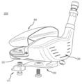
본원에 정의되고 아래에서 사용되는 바와 같은, 페어웨이 유형 골프 클럽 헤드의 "후방 추 조립체"(1100)는, 후방 추(1111), 후방 추 나사산 형성 체결구(1160), 및 후방 추 와셔(1170)를 포함하는, 후방 추 조립체(1100)를 포함하는 제거 가능하거나, 조정 가능하거나, 교환 가능한 추 조립체이다. 도 2a 내지 도 2c 및 도 6a를 참조하면, 후방 추 홈(250)이 후방 추 지지 구조체(299)에 의해 감싸여 있다. As defined herein and used below, a “rear weight assembly” 1100 of a fairway type golf club head includes a
본원에 정의되고 아래에서 사용되는 바와 같은, 페어웨이 유형 골프 클럽 헤드의 "후방 추"(1111)는 후방 추 홈(250)의 내부에 적어도 부분적으로 수용되도록 구성된 탈착 가능한 추 구성 요소이다. 도 5d, 도 6a 및 도 6b를 참조하면, 후방 추가 후방 추 높이(1112), 후방 추 폭(1114)(도시하지 않음), 후방 추 길이(1116), 후방 추 상면(1120), 후방 추 저면(1124), 상면과 저면 사이의 후방 추 둘레 표면(1128), 후방 추 돌출부(1130), 상측 와셔 홈(1140), 후방 추 체결구 구멍(1150), 및 체결구 구멍(1150) 내부의 후방 추 구멍 견부(1154)를 포함한다. 나사산 형성 체결구(1160)는 나사산 형성 체결구(1160)의 헤드가 구멍 견부(1154)에 맞닿을 때까지 저면(1124)으로부터 체결구 구멍(1150) 내로 상방으로 삽입된다. 나사산 형성 체결구(1160)의 일부가 상면(1120)을 지나쳐 연장된다. 추 와셔(1170)가 나사산 형성 체결구(1160)의 위에 수용되며, 추 와셔(1170)가 또한 상측 와셔 홈(1140)의 내부에 수용된다. 이 후방 추 조립체는 완전히 조립되고 나면 후방 추 홈(250) 내부에 수용될 수 있으며, 여기서 나사산 형성 체결구(1160)가 후방 추 체결구 구멍(255)의 내부에 나사 체결에 의해 수용된다. 후방 추 저면(1124)이 페어웨이 유형 골프 클럽 헤드의 하측 외부에 노출된다. 후방 추 돌출부(1130)가 페어웨이 유형 골프 클럽 헤드의 하측 및 후방 외부 모두에 노출된다. As defined herein and used below, the “back weight” 1111 of a fairway type golf club head is a removable weight component configured to be received at least partially inside the
III. 좌표계 III. coordinate system
본 발명을 설명하는 다양한 무게 중심, FLIP 축선, 및 페어웨이 유형 클럽 헤드 치수를 달성하기 위해, 페어웨이 유형 클럽 헤드에 적용되는 2개의 좌표계가 아래에서 설명된다. Two coordinate systems applied to a fairway type club head are described below to achieve the various center of gravity, FLIP axis, and fairway type club head dimensions that describe the present invention.
본원에 설명된 바와 같은, 페어웨이 유형 골프 클럽 헤드의 "XYZ" 좌표계는 타격 페이스(104)의 기하학적 중심(140)에 기초한다. 본원에 설명된 바와 같은 페어웨이 유형 클럽 헤드 치수가 아래에 정의된 바와 같은 좌표계에 기초하여 측정될 수 있다. 타격 페이스(104)의 기하학적 중심(140)이 타격 페이스(104)의 기하학적 중심(140)에 위치한 원점을 갖는 좌표계를 정의한다. 이 좌표계는 X-축선(1052), Y-축선(1062), 및 Z-축선(1072)을 정의한다. X-축선(1052)이 타격 페이스(104)의 기하학적 중심(140)을 통해 페어웨이 유형 클럽 헤드(100)의 힐(120)로부터 토우(122)의 방향으로 연장된다. Y-축선(1062)이 타격 페이스(104)의 기하학적 중심(140)을 통해 페어웨이 유형 클럽 헤드(100)의 크라운(116)으로부터 솔(118)의 방향으로 연장된다. Y-축선(1062)은 X-축선(1052)에 수직이다. Z-축선(1072)이 타격 페이스(104)의 기하학적 중심(140)을 통해 페어웨이 유형 클럽 헤드(100)의 전방 단부(108)로부터 후방 단부(110)의 방향으로 연장된다. Z-축선(1072)은 X-축선(1052)과 Y-축선(1062) 모두에 수직이다.As described herein, the “XYZ” coordinate system of a fairway type golf club head is based on the
본원에 설명된 바와 같은 페어웨이 유형 골프 클럽 헤드의 XYZ 좌표계는 X-축선(1052) 및 Y-축선(1062)을 통해 연장되는 XY 평면을 정의한다. 좌표계는 X-축선(1052) 및 Z-축선(1072)을 통해 연장되는 XZ 평면을 정의한다. 좌표계는 Y-축선(1062) 및 Z-축선(1072)을 통해 연장되는 YZ 평면을 정의한다. XY 평면, XZ 평면, YZ 평면은 모두 서로 수직이며, 타격 페이스(104)의 기하학적 중심(140)에 위치한 좌표계 원점에서 서로 교차한다. XY 평면은 호젤 축선(132)에 평행하게 연장되며, 로프트 평면(1010)으로부터 페어웨이 유형 클럽 헤드(100)의 로프트각에 대응하는 각도에 위치한다. 이러한 실시예 또는 다른 실시예에서, 타격 페이스(104)를 XY 평면에 수직인 방향에서 보면 이것이 페어웨이 유형 클럽 헤드(100)의 정면도(도 1b)일 수 있다. 또한, 이러한 또는 다른 실시예에서, 힐(120)을 YZ 평면에 수직인 방향에서 보면 이것이 페어웨이 유형 클럽 헤드(100)의 측면도 또는 측단면도(도 1a)일 수 있다. The XYZ coordinate system of a fairway type golf club head as described herein defines an XY plane extending through
본원에 설명된 바와 같은, 페어웨이 유형 골프 클럽 헤드의 "xyz" 좌표계는 페어웨이 유형 클럽 헤드 CG(172)에 기초한다. xyz 좌표계는 기하학적 중심(140)에 기초한 XYZ 좌표계와 상이하다. 페어웨이 유형 클럽 헤드 CG(172)는 x-축선(1050), y-축선(1060), 및 z-축선(1070)을 갖는 좌표계의 원점을 정의한다. y-축선(1060)이 헤드 CG(172)를 통해 페어웨이 유형 클럽 헤드(100)의 크라운(116)으로부터 솔(118)의 방향으로 연장된다. x-축선(1050)이, 정면도에서 볼 때 y-축선(1060)에 수직으로 그리고 XY 평면에 평행하게, 힐(120)로부터 토우(122)까지 헤드 CG(172)를 통해 연장된다. z-축선(1070)이 전방 단부(108)로부터 후방 단부(110)까지 헤드 CG(172)를 통해 연장되며, x-축선(1050) 및 y-축선에 수직이다. 많은 실시예에서, x-축선(1050)이 힐(120)로부터 토우(122)까지 헤드 CG(172)를 통해 X-축선(1052)에 평행하게 연장된다. y-축선(1060)이 Y-축선(1062)에 평행하게 크라운(116)으로부터 솔(118)까지 헤드 CG(172)를 통해 연장된다. z-축선(1070)이 전방 단부(108)로부터 후방 단부(110)까지 헤드 CG(172)를 통해 연장되며, Z-축선(1072)에 평행하다. As described herein, the “xyz” coordinate system of a fairway type golf club head is based on fairway type
본원에 설명된 바와 같은, 페어웨이 유형 골프 클럽 헤드의 "로프트 평면"(1010)은 타격 페이스(104)의 기하학적 중심(140)의 접선 방향의 평면이다. 로프트 평면(1010)은 지면(1000)과 로프트각을 형성한다. As described herein, the “loft plane” 1010 of a fairway type golf club head is the plane tangential to the
IV.IV. CG 위치를 결정하기 위한 방법 Methods for determining CG location
페어웨이 유형 클럽 헤드 CG(172) 및 솔 인서트 CG(472)가 상이한 페어웨이 유형 골프 클럽 헤드 구성 요소의 위치에 대해 설명될 수 있다. 아래에 설명된 바와 같은 바람직한 CG(172, 472) 위치를 설명하기 위한 여러 가지 방법이 개발되었다. 페어웨이 유형 클럽 헤드 CG(172)와 솔 인서트 CG(472)가 이들 방법의 임의의 조합을 사용하여 설명될 수 있다. 각각의 방법은 CG(172)가 최적으로 위치될 "가상의 부피" 또는 페어웨이 유형 클럽 헤드(100) 내부의 부피를 확립한다. 도 5a 내지 도 5d 및 도 8a 내지 도 8e는 페어웨이 유형 클럽 헤드(100) 내부의 부피를 2차원 영역(축척에 맞게 도시되지 않음)으로 예시한다. 이 2차원 영역이 페어웨이 유형 클럽 헤드(도시하지 않음) 내부의 3차원 부피로서 이상화될 수 있다. CG(172, 472)가 지정된 면적 또는 지정된 부피로 제한될 수 있다. 아래에 설명된 오프셋은 절대값일 수도 있으며, 또는 정의 지점으로부터 임의의 방향으로 오프셋될 수도 있다. 예를 들어, CGX1이 Y-축선(1062)으로부터 힐방향 또는 토우방향으로 오프셋될 수도 있다. Fairway type
본원에 정의되고 아래에서 사용되는 바와 같은, CG 위치(172, 472)를 결정하기 위한 "기하학적 중심 방법"은 페이스(140)의 기하학적 중심에서 시작되는 XYZ 좌표계에 대해 설명된다. 기하학적 중심 방법은 페어웨이 유형 클럽 헤드 CG(172)와 솔 인서트 CG(472)의 위치를 결정하는 데 사용될 수 있다. 페어웨이 유형 클럽 헤드 CG(172)는 오프셋(CGX1)(173), 오프셋(CGY1)(176), 및 오프셋(CGZ1)(174)에 위치한다. 솔 인서트 CG(472)는 오프셋(CGX1)(473), 오프셋(CGY1)(476), 및 오프셋(CGZ1)(474)에 위치한다. 페어웨이 유형 클럽 헤드 CG(172)와 솔 인서트 CG(472)가 이 방법을 사용하여 유사하게 설명될 수 있긴 하지만, 페어웨이 유형 클럽 헤드 CG(172)와 솔 인서트 CG(472)에 대해 얻은 값은 동일할 수도 또는 동일하지 않을 수도 있다. 다시 말해, CGZ1(174), CGY1(176), 및 CGX1(173)은 페어웨이 유형 클럽 헤드 CG(172)와 관련이 있으며, CGZ1(474), CGY1(476), 및 CGX1(473)은 솔 인서트 CG(472)와 관련이 있다. 도 5a 및 도 8a를 참조하면, CG(172, 472)는 Z-축선(1072)에 평행하게 기하학적 중심(140)으로부터 후방으로 측정된 오프셋(CGZ1)(174, 474)에 위치한다. CG(172, 472)는, CG(172, 472)로부터 Z-축선(1072)까지 수직으로 측정된, 오프셋(CGY1)(176, 476)에 추가로 위치한다. CG(172, 472)가 기하학적 중심(140)의 위 또는 아래에 있을 수 있다. 다시 말해, CGY1은 Z-축선(1072)으로부터의 절대값이다. CG는 기하학적 중심(140)으로부터 X-축선(1052)에 평행하게 측정된 오프셋(CGX1)(173, 473)에 추가로 위치한다(도시하지 않음). CG(172, 472)가 기하학적 중심(140)에 대해 힐방향 또는 토우방향일 수 있다. 다시 말해, CGX1(173, 473)은 Y-축선(1062)으로부터의 절대값이다. 기하학적 중심 방법을 사용하여, 페어웨이 유형 클럽 헤드 CG(172)와 솔 인서트 CG(472)를 중심으로 최소 및 최대 CGX1, CGY1, 및 CGZ1 값에 의해 별도의 가상의 상자가 정의될 수 있다. CGX1(173, 473)은 힐-토우 방향으로 상자를 정의할 수 있으며, CGY1(176, 476)은 크라운-솔 방향으로 상자를 정의할 수 있으며, CGZ1(174, 474)은 전후 방향으로 상자를 정의할 수 있다. 이 가상의 상자는 최적의 CG(172, 472) 값의 범위를 정의할 수 있다. 페어웨이 유형 클럽 헤드 CG(172)의 주위에 그려진 가상의 상자가 솔 인서트 CG(472)의 주위에 그려진 가상의 상자보다 크라운과 타격 페이스에 더 가깝게 위치할 수 있다. As defined herein and used below, the “geometric center method” for determining
본원에 정의되고 아래에서 사용되는 바와 같은, CG 위치(172, 472)를 결정하기 위한 "전단 가장자리 방법"이 페어웨이 유형 클럽 헤드 전단 가장자리(114)에 대해 설명된다. 전단 가장자리 방법은 페어웨이 유형 클럽 헤드 CG(172)와 솔 인서트 CG(472)의 위치를 결정하는 데 사용될 수 있다. 페어웨이 유형 클럽 헤드 CG(172)는 오프셋(CGX1)(173), 오프셋(CGY2)(180), 및 오프셋(CGZ2)(181)에 위치한다. 솔 인서트 CG(472)는 오프셋(CGX1)(473), 오프셋(CGY2)(480), 및 오프셋(CGZ2)(481)에 위치한다. 페어웨이 유형 클럽 헤드 CG(172)와 솔 인서트 CG(472)가 이 방법을 사용하여 유사하게 설명될 수 있긴 하지만, 페어웨이 유형 클럽 헤드 CG(172)와 솔 인서트 CG(472)에 대해 얻은 값은 동일할 수도 또는 동일하지 않을 수도 있다. 다시 말해, CGZ2(181), CGY2(180) 및 CGX1(173)은 페어웨이 유형 클럽 헤드 CG(172)와 관련이 있으며, CGZ2(481), CGY2(480) 및 CGX1(473)은 솔 인서트 CG(472)와 관련이 있다. 도 5b 및 도 8b를 참조하면, CG(172, 472)는 지면(1000)에 수직으로 측정된 오프셋(CGY2)(180, 480)에 위치한다. CG(172, 472)는 지면(1000)에 평행하게 전단 가장자리(114)로부터 CG(172, 472)까지 후방으로 측정된 오프셋(CGZ2)(181, 481)에 추가로 위치한다. CG는 기하학적 중심(140)으로부터 X-축선(1052)에 평행하게 측정된 오프셋(CGX1)(173, 473)에 추가로 위치한다(도시하지 않음). CG(172, 472)가 기하학적 중심(140)에 대해 힐방향 또는 토우방향일 수 있다. 다시 말해, CGX1(173, 473)은 Y-축선(1062)으로부터의 절대값이다. 페어웨이 유형 클럽 헤드를 정면에서 볼 때, 전단 가장자리는 Y-축선(1062)을 따른 일 지점으로서 이상화된다. 이 때문에, X-축선(1062) 방향에서의 CG(172, 472)의 위치는 기하학적 중심(140)에 기초한다. 전단 가장자리 방법을 사용하여, 페어웨이 유형 클럽 헤드 CG(172)와 솔 인서트 CG(472)를 중심으로 최소 및 최대 CGX1, CGY1, 및 CGZ1 값에 의해 별도의 가상의 상자가 정의될 수 있다. CGX1(173, 473)은 힐-토우 방향으로 상자를 정의할 수 있으며, CGY2(180, 480)는 크라운-솔 방향으로 상자를 정의할 수 있으며, CGZ2(181, 481)는 전후 방향으로 상자를 정의할 수 있다. 가상의 상자가 최적의 CG(172, 472) 값의 범위를 정의할 수 있다. 페어웨이 유형 클럽 헤드 CG(172)의 주위에 그려진 가상 상자가 솔 인서트 CG(472)의 주위에 그려진 가상 상자보다 크라운과 타격 페이스에 더 가깝게 위치할 수 있다. As defined herein and used below, a “leading edge method” for determining a
본원에 정의되고 아래에서 사용되는 바와 같은, CG 위치(172, 472)를 결정하기 위한 "출구 지점 방법(exit point method)"은 FLIP 축선 출구 지점(196)에 대해 설명된다. 출구 지점 방법이 페어웨이 유형 클럽 헤드 CG(172)와 솔 인서트 CG(472)의 위치를 결정하는 데 사용될 수 있다. 페어웨이 유형 클럽 헤드 CG(172)는 오프셋(CGX2)(179), 오프셋(CGY2)(180), 및 오프셋(CGZ3)(187)에 위치한다. 솔 인서트 CG(472)는 오프셋(CGX2)(479), 오프셋(CGY2)(480), 및 오프셋(CGZ3)(487)에 위치한다. 페어웨이 유형 클럽 헤드 CG(172)와 솔 인서트 CG(472)가 이 방법을 사용하여 유사하게 설명될 수 있긴 하지만, 페어웨이 유형 클럽 헤드 CG(172)와 솔 인서트 CG(472)에 대해 얻은 값은 동일할 수도 또는 동일하지 않을 수도 있다. 다시 말해, CGZ3(187), CGY2(180) 및 CGX2(179)은 페어웨이 유형 클럽 헤드 CG(172)와 관련이 있으며, CGZ3(487), CGY2(480) 및 CGX2(479)은 솔 인서트 CG(472)와 관련이 있다. 도 5c 및 도 8c를 참조하면, CG(172, 472)는 지면(1000)에 수직으로 측정된 오프셋(CGY2)(180, 480)에 위치한다. CG(172, 472)는 지면(1000)에 평행하게 출구 지점(196)으로부터 CG(172, 472)까지 전방으로 측정된 오프셋(CGZ3)(187, 487)에 추가로 위치한다. CG는 FLIP 축선(195)(도시하지 않음)으로부터 X-축선(1052)에 평행하게 측정된 오프셋(CGX2)(179, 479)에 추가로 위치한다(도시하지 않음). CG(172, 472)가 FLIP(190)에 비해 힐방향 또는 토우방향일 수 있다. 다시 말해, CGX2(179, 479)는 FLIP-축선(195)으로부터의 절대값이다. 출구 지점 방법을 사용하여, 페어웨이 유형 클럽 헤드 CG(172)와 솔 인서트 CG(472)를 중심으로 최소 및 최대 CGX2, CGY2, 및 CGZ3 값에 의해 별도의 가상의 상자가 정의될 수 있다 CGX2(179,479)는 힐-토우 방향으로 상자를 정의할 수 있으며, CGY2(180, 480)는 크라운-솔 방향으로 상자를 정의할 수 있으며, CGZ3(187, 487)는 전후 방향으로 상자를 정의할 수 있다. 가상의 상자가 최적의 CG(172, 472) 값의 범위를 정의할 수 있다. 페어웨이 유형 클럽 헤드 CG(172)의 주위에 그려진 가상의 상자가 솔 인서트 CG(472)의 주위에 그려진 가상의 상자보다 크라운과 타격 페이스에 더 가깝게 위치할 수 있다. As defined herein and used below, an “exit point method” for determining the
본원에 정의되고 아래에서 사용되는 바와 같은, CG 위치(172, 472)를 결정하기 위한 "FLIP 축선 방법"은 FLIP 축선(195)에 대해 설명된다. FLIP 축선 방법이 페어웨이 유형 클럽 헤드 CG(172)와 솔 인서트 CG(472)의 위치를 결정하는 데 사용될 수 있다. 페어웨이 유형 클럽 헤드 CG(172)는 오프셋(CGF1)(186)과 오프셋(CGF2)(182)에 위치된다. 솔 인서트 CG(472)는 오프셋(CGF1)(486) 및 오프셋(CGF2)(482)에 위치된다. 페어웨이 유형 클럽 헤드 CG(172)와 솔 인서트 CG(472)가 이 방법을 사용하여 유사하게 설명될 수 있긴 하지만, 페어웨이 유형 클럽 헤드 CG(172)와 솔 인서트 CG(472)에 대해 얻은 값은 동일할 수도 또는 동일하지 않을 수도 있다. 다시 말해, CGF2(182) 및 CGF1(186)은 페어웨이 유형 클럽 헤드 CG(172)와 관련이 있으며, CGF2(482) 및 CGF1(486)은 솔 인서트 CG(472)와 관련이 있다. 도 5d 및 도 8d를 참조하면, CG(172, 472)는, CG(172, 472)로부터 FLIP-축선(195)까지 수직으로 측정된, 오프셋(CGF1)(186, 486)에 위치한다. CG(172, 472)가 FLIP 축선(195)의 위 또는 아래에 있을 수 있다. 다시 말해, CGF1(186, 486)은 FLIP 축선(195)으로부터의 절대값이며, FLIP 축선(195)으로부터 떨어진 반경 방향 거리를 정의한다. CG(172, 472)는 CG(172)를 통과하고 FLIP 축선(195)에 평행한 평면(1020, 1030)을 따라 측정된 오프셋(CGF2)(182, 482)에 추가로 위치한다. FLIP 축선 방법을 사용하여, CGF1 및 CGF2 값의 범위를 정의함으로써 페어웨이 유형 클럽 헤드 CG(172)와 솔 인서트 CG(472)를 중심으로 별도의 가상의 원통이 정의될 수 있다. CGF1(186, 486) 값은 원통의 반지름을 정의할 수 있으며, CGF2(182, 482) 값은 FLIP 축선(195)을 따라 원통의 높이를 정의할 수 있다. 가상의 원통이 최적의 CG(172, 472) 값의 범위를 정의할 수 있다. 페어웨이 유형 클럽 헤드 CG(172) 주위에 그려진 가상의 원통이 솔 인서트 CG(472)의 주위에 그려진 가상의 상자보다 크라운과 타격 페이스에 더 가깝게 위치할 수 있다. As defined herein and used below, a “FLIP axis method” for determining
본원에 정의되고 아래에서 사용되는 바와 같은, 솔 인서트 CG 위치(472)를 결정하기 위한 "상대적 방법"은 페어웨이 유형 클럽 헤드 CG(172)에서 시작되는 좌표계에 대해 설명된다. 도 8e를 참조하면, 솔 인서트 CG(472)는 솔 인서트 CG(472)로부터 z-축선(1070)까지 수직으로 측정된 오프셋(CGY4)(477)에 위치한다, CG(172, 472)는 솔 인서트 CG(472)로부터 y-축선(1060)까지 수직으로 측정된 오프셋(CGZ5)(475)에 추가로 위치한다. 솔 인서트 CG(472)는 페어웨이 유형 클럽 헤드 CG(172)의 아래에 후방으로 위치할 수 있다. CG는 페어웨이 유형 클럽 헤드 CG(172)로부터 솔 인서트 CG(472)까지 X-축선(1052)에 평행하게 측정된 오프셋(CGX3)(483)에 추가로 위치한다(도시하지 않음). 상대적 방법을 사용하여, 최소 및 최대 CGX3, CGY4, 및 CGZ5 값에 의해 솔 인서트 CG(472)의 주위에 가상의 상자가 정의될 수 있다. CGX2(483)은 힐-토우 방향으로 상자를 정의할 수 있으며, CGY4(477) 값은 크라운-솔 방향으로 상자를 정의할 수 있으며, CGZ5(475)는 전후 방향으로 상자를 정의할 수 있다. 가상의 상자가 최적의 CG(472) 값의 범위를 정의할 수 있다. As defined herein and used below, a “relative method” for determining sole
경량 크라운 인서트(800), 본체(202), 고밀도 솔 인서트(430), 및 제거 가능하거나, 조정 가능하거나, 교환 가능한 후방 추 조립체(1100)의 조합이 솔 인서트가 없는 페어웨이 유형 클럽 헤드에 비해 골프공 스핀을 완화하며 감소시키는 낮은 무게 중심을 가진 페어웨이 유형 골프 클럽 헤드를 제공한다. 본원에서 설명되는 페어웨이 유형 골프 클럽 헤드(100)는 고밀도 솔 인서트(430), 경량 크라운 인서트(800), 및 제거 가능하거나, 조정 가능하거나 교환 가능한 후방 추 조립체(1100)를 사용하여 FLIP 축선(195)을 따라 CG(172)의 균형을 맞춘다. The combination of
FLIP 축선(195) 상에 낮은 후방 CG(172)를 달성하는 페어웨이 유형 골프 클럽 헤드(100)의 다양한 실시예가 있다. 본체(202) 및 페이스 컵(300)이 티타늄 합금과 같은 금속 재료를 포함할 수 있으며, 또는 본체(202)가 섬유 강화 중합체 또는 섬유 강화 합성물과 같은 복합 재료를 포함할 수 있다. 솔 인서트(430) 및 후방 추(1111)가 티타늄 또는 강철과 같은 조밀한 금속 재료를 포함할 수 있다. 크라운 인서트(800)가 탄소 복합 재료, 섬유 강화 중합체성 재료, 천연 섬유 합성물, 또는 임의의 다른 적합한 저밀도 재료와 같은 복합 재료를 포함할 수 있다.There are various embodiments of a fairway type
클럽 헤드의 다양한 실시예가 다양한 로프트 각도 및 부피를 가질 수 있다. 다른 실시예는 본원에 설명된 로프트각 및 부피와 상이한 로프트각 또는 부피를 갖는 클럽 헤드를 포함할 수 있다. Different embodiments of club heads may have different loft angles and volumes. Other embodiments may include a club head having a loft angle or volume different from the loft angle and volume described herein.
상세한 설명details
I. 포스 라인 임팩트 지점 및 포스 라인 축선I. Force Line Impact Point and Force Line Axis
도 1a 및 도 1b를 참조하면, 페어웨이 유형 골프 클럽 헤드(100)는 골프공을 타격할 때 전달되는 힘을 최대화하기 위해 CG가 포스 라인 근처 또는 포스 라인 상에 있도록 하는 일련의 구조체를 포함한다. 포스 라인 임팩트 지점(FLIP)(190)은 페어웨이 유형 골프 클럽 타격력이 골프공에 가장 효율적으로 전달되는 지점이다. 가장 효율적인 전달은 골프공에 전달되는 힘을 최대화하며, 측면 벡터의 임의의 힘을 소모하지 않고 발생한다. 따라서, FLIP 축선(195)은 임팩트에서 측면 스핀 벡터/상측 스핀 벡터/또는 하측 스핀 벡터를 골프공 내로 배치하지 않는 힘 벡터와 합동인 축선이다. FLIP(190)은 임팩트 지점으로서, 타격 페이스(104) 상의 FLIP 축선(195)과의 교차점이며, 지면에 놓인 골프공의 평균 최적 임팩트 위치로부터 전개된다. 다시 말해, FLIP(190)은 FLIP 축선(195)의 원점을 정의하는 지점이다. 골프공의 평균 최적 임팩트 위치는 임팩트 순간에 페어웨이 유형 골프 클럽 헤드(100)의 롤 반경/페이스 곡률이 골프공에 접하는 골프공 상의 대략적인 지점이다. 이 임팩트 위치는 본질적으로 페어웨이 유형 골프 클럽의 바운스 각도에 의해 변하지 않는데, 그 이유는 페어웨이 유형 골프 클럽의 솔의 바운스 부분은 실제로, 임팩트 시에 볼이 놓이는 지면의 아래에 있도록(따라서 디보트를 취함) 설계되었기 때문이다. 이 원하는 임팩트 위치는 또한, 골프공의 물리적 치수가 페어웨이 유형 골프 클럽 헤드 치수가 변함에 따라 커지거나 작아지는 것은 아니기 때문에, 기본적으로 타격 페이스 높이에 의해 변경되지는 않는다. 따라서, 본원에 설명된 골프 클럽이 드라이버 유형 골프 클럽은 아닌 것이며, 하이브리드 유형 골프 클럽도 아닌 것이며, 아이언 유형 골프 클럽도 아닌 것이며, 퍼터 유형 골프 클럽도 아닌 것이다.Referring to FIGS. 1A and 1B , a fairway type
따라서, 이 바람직한 또는 최적의 정적 포스 라인 임팩트 지점(FLIP(190))은 페어웨이 유형 골프 클럽 헤드 타격 페이스(104) 상의 비교적 일정한 지점이며(본질적으로 페어웨이 유형 골프 클럽 솔 바운스 각도 및 깊이 또는 타격 페이스 높이에 의해 변경되지 않음), 골프공 임팩트를 위한 가장 효율적인 힘 벡터의 타격 페이스 단부 지점에 위치한다. 결과적으로, CG(172)가 FLIP 축선(195) 상에 직접 위치하였다면, 충격력 일부를 낭비하여 골프공에 상측/하측/또는 측면 스핀을 부과하는 측면 벡터에 대해 임의의 충격력을 잃지 않는 방식으로 CG(172)가 이 FLIP 축선(195)을 따라 이 충격력에 반응하였을 것이다. 도 1a를 참조하면, FLIP(포스 라인 임팩트 지점)(190)는 지면(1000) 위의 FLIP 높이(192)에 있는 타격 페이스 및 YZ 평면 상에 위치한다. FLIP 높이(192)가 0.55 인치 내지 0.75 인치의 범위 이내이다. FLIP 높이(192)가 0.55 인치, 0.56 인치, 0.57 인치, 0.58 인치, 0.59 인치, 0.60 인치, 0.61 인치, 0.62 인치, 0.63 인치, 0.64 인치, 0.65 인치, 0.66 인치, 0.67 인치, 0.68 인치, 0.69 인치, 0.70 인치, 0.71 인치, 0.72 인치, 0.73 인치, 0.74 인치 또는 0.75 인치일 수도 있다.Thus, this preferred or optimal static force line impact point (FLIP 190) is a relatively constant point on the fairway type golf club head striking face 104 (essentially fairway type golf club sole bounce angle and depth or striking face height). not changed by ), located at the end of the striking face of the most efficient force vector for golf ball impact. As a result, if
위에 정의된 바와 같은, 페어웨이 유형 골프 클럽 헤드는 크라운 인서트, 페이스 컵, 고밀도 솔 인서트 및 후방 추로 구성된 그룹으로부터 선택된 특징을 포함한다. 이 구성은 FLIP 축선 상에 또는 그 근처에 그리고 전후 방향으로 최적으로 위치 결정된 페어웨이 유형 골프 클럽 헤드 CG의 바람직한 위치를 허용하는 질량 분포를 제공한다. 구체적으로, 각각의 구성 요소에 대해 특정 재료를 선택하는 것은 페어웨이 유형 골프 클럽 헤드의 하부 부분의 질량 비율을 높이는 것을 지원한다. 또한, 페어웨이 유형 골프 클럽 헤드의 전체 형상도 바람직한 CG 위치를 지원한다. 구체적으로, 아래에 설명된 타격 페이스와 클럽 헤드의 상대적인 높이도 더 낮은 CG 배치를 지원한다. CG를 더 낮게 배치함으로써 CG가 FLIP 축선 상에 또는 그 근처에 있을 수 있으며, 또한 페어웨이 유형 골프 클럽 헤드의 후방을 향해 더 멀리 배치될 수 있다. 본원에 설명된 구조 및 구조적 관계 중 하나 이상을 조합하면 보다 최적의 페어웨이 유형 골프 클럽 헤드 CG 배치가 제공된다.As defined above, a fairway type golf club head includes features selected from the group consisting of a crown insert, a face cup, a high density sole insert and a back weight. This configuration provides a mass distribution that allows for preferred positioning of the fairway type golf club head CG optimally positioned on or near the FLIP axis and in the fore-aft direction. Specifically, selecting specific materials for each component supports increasing the mass ratio of the lower portion of a fairway type golf club head. Additionally, the overall shape of the fairway type golf club head also supports the preferred CG location. Specifically, the relative heights of the striking face and club head described below also support a lower CG placement. By placing the CG lower, the CG can be on or near the FLIP axis, and also further towards the rear of the fairway type golf club head. Combining one or more of the structures and structural relationships described herein provides a more optimal fairway type golf club head CG placement.
페어웨이 유형 골프 클럽 헤드의 다양한 비율이 페어웨이 유형 클럽 헤드 구성 요소의 치수 사이의 관계를 입증하기 위해 전개될 수 있다. 아래에서 논의되는 비율은 페어웨이 유형 클럽 헤드(100)에 대한 것이다. 이 비율은 드라이버 유형이나, 하이브리드 유형이나, 아이언 유형, 또는 퍼터 유형 클럽 헤드에 대한 것은 아니다. 페어웨이 유형 클럽 헤드(100)는 아래의 관계 중 어느 하나 이상을 사용하여 설명될 수 있다. Various proportions of the fairway type golf club head can be developed to demonstrate the relationship between the dimensions of the fairway type club head components. The proportions discussed below are for a fairway
(1) ![]()
![]()
(2)![]()
![]()
제 1 비율(1)은 페어웨이 유형 클럽 헤드 높이(164)와 기하학적 중심 높이(146) 사이의 관계를 전개한 것이다. 클럽 헤드 높이(164)는 지면(1000)에 수직으로 측정할 때 1.25 인치 내지 2.00 인치이어야 하며, 기하학적 중심 높이(146)는 0.40 인치 내지 0.75 인치이어야 한다. 페어웨이 유형 클럽 헤드(100)는 2.30 미만의 제 1 비율(1)을 갖는 것으로 설명될 수 있다. 예시적인 일 실시예에서, 페어웨이 유형 클럽 헤드(100)는 2.15의 제 1 비율(1)을 갖는다. The first ratio (1) is the development of the relationship between fairway type club head height (164) and geometric center height (146). The
제 2 비율(2)은 클럽 헤드 높이(164)와 페이스 높이(144) 사이의 관계를 전개한 것이다. 클럽 헤드 높이(164)는 지면(1000)에 수직으로 측정할 때 1.25 인치 내지 2.00 인치이어야 하며, 페이스 높이(144)는 페이스(140)의 기하학적 중심을 통해 연장되는 로프트 평면(1010)에 평행하게 측정할 때 1.00 인치 내지 1.50 인치이어야 한다. 페어웨이 유형 클럽 헤드(100)는 1.50 미만의 제 2 비율(2)을 갖는 것으로 설명될 수 있다. 예시적인 일 실시예에서, 페어웨이 유형 클럽 헤드(100)는 1.28의 제 2 비율(2)을 갖는다. The second ratio (2) develops the relationship between club head height (164) and face height (144).
페어웨이 유형의 골프 클럽 헤드 치수는 클럽 헤드 기하학적 형상과 FLIP 축선(195) 사이의 관계를 전개하는 데 사용될 수 있다. 예를 들어, 페어웨이 유형 골프 클럽 헤드는 아래의 관계를 사용하여 설명될 수 있다.The fairway type golf club head dimensions can be used to develop a relationship between the club head geometry and the
(3) ![]()
![]()
(4) ![]()
![]()
(5) ![]()
![]()
제 3 비율(3)은 FLIP 높이(192)와 페이스의 기하학적 중심 높이(146) 사이의 관계를 전개한 것이다. FLIP 높이(192)는 0.55 인치 내지 0.75 인치이어야 하며, 기하학적 중심 높이(146)는 0.40 인치 내지 0.75 인치이여야 한다. 제 3 비율(3)은 FLIP(190)와 기하학적 중심(140)이 서로 가까이 위치하도록 지정된 범위로 제한된다. 다시 말해, 제 3 비율(3)은 클럽 헤드(100)를 페어웨이 유형 클럽 헤드로 제한한다. 예시적인 일 실시예에서, 페어웨이 유형 클럽 헤드(100)는 0.98의 제 3 비율을 갖는다. The third ratio (3) is the development of the relationship between the FLIP height (192) and the height of the geometric center of the face (146).
제 4 비율(4)은 FLIP 높이(192)와 클럽 헤드 높이(164) 사이의 관계를 전개한 것이다. FLIP 높이(192)는 지면(1000)에 수직으로 측정할 때 0.55 인치 내지 0.75 인치 이내이어야 하며, 클럽 헤드 높이(164)는 지면(1000)에 수직으로 측정할 때 1.25 인치 내지 2.00 인치이어야 한다. 제 4 비율(4)은 FLIP 높이(192)를 클럽 헤드 높이(164)의 대략 절반 또는 절반보다 약간 작게 제한하도록 지정된 범위로 제한된다. 이와 같이, 제 4 비율(4)은 클럽 헤드(100)가 페어웨이 유형 클럽 헤드라는 것을 추가로 확립한다. 예시적인 일 실시예에서, 클럽 헤드(100)는 0.45의 제 4 비율(4)을 갖는다.A fourth ratio (4) develops the relationship between FLIP height (192) and club head height (164).
제 5 비율(5)은 FLIP 높이(192)와 페이스 높이(144) 사이의 관계를 전개한 것이다. 클럽 헤드 높이(192)는 페이스(140)의 기하학적 중심을 통해 연장되는 로프트 평면(1010)에 평행하게 측정할 때 0.55 인치 내지 0.75 인치 이내이어야 하며, 페이스 높이(144)는 1.00 인치 내지 1.50 인치이어야 한다. 제 5 비율(5)은 FLIP 높이(192)를 페이스 높이(144)의 대략 절반으로 제한하기 위해 지정된 범위로 제한된다. 이와 같이, 제 5 비율(5)은 클럽 헤드(100)가 페어웨이 유형 클럽 헤드라는 것을 추가로 확립한다. 예시적인 일 실시예에서, 클럽 헤드(100)는 0.58의 제 5 비율(5)을 갖는다.The fifth ratio (5) is the development of the relationship between FLIP height (192) and face height (144).
V. 클럽 헤드 무게 중심 V. Club Head Center of Gravity
페어웨이 유형 골프 클럽 헤드 CG(172)에 대한 아래의 지정된 범위 및 위의 정의는 클럽 헤드를 페어웨이 유형 클럽 헤드로 제한한다. 다시 말해, 페어웨이 유형 골프 클럽 헤드는 드라이버 유형, 하이브리드 유형, 아이언 유형, 또는 퍼터 유형 골프 클럽 헤드일 수 없다. 도 5a 내지 도 5d에 도시된 바와 같이, 페어웨이 유형 골프 클럽 헤드(100)는 FLIP 축선(195) 상에 또는 그 근처에 있는 낮게 최적으로 배치된 무게 중심(CG)(172)을 정의한다. 각각의 방법은 클럽 헤드(100) 내부의 CG(172)가 최적으로 위치될 부피를 확립한다. 클럽 헤드 CG 위치(172)는 이들 방법의 임의의 조합을 사용하여 설명될 수 있다. The ranges specified below and definitions above for fairway type golf
A. 기하학적 중심 방법A. Geometric center method
경량 크라운 인서트(800), 본체(202), 고밀도 솔 인서트(430), 제거 가능하거나, 조정 가능하거나, 교환 가능한 후방 추 조립체(1100) 또는 이들의 조합은, 솔 인서트가 없는 클럽 헤드에 비해, 골프공 스핀을 완화하며 감소시키는 낮은 무게 중심을 가진 골프 클럽 헤드를 제공한다. 이러한 페어웨이 유형 골프 클럽 헤드 구성 요소는 본원에 설명된 CG(172) 위치에 대한 기준을 제공한다. 본원에 설명된 페어웨이 유형 골프 클럽 헤드(100)는, FLIP 축선(195)을 따라 CG(172)의 균형을 맞추기 위해, 고밀도 솔 인서트(430), 경량 크라운 인서트(800), 제거 가능하거나, 조정 가능하거나, 교환 가능한 후방 추 조립체(1100), 또는 이들의 조합으로 이루어진 그룹으로부터 선택된 특징을 포함한다. 본원에 정의된 CG(172)의 위치 범위는 70 g 내지 90 g 범위의 질량을 갖는 고밀도 솔 인서트를 필요로 한다.The
기하학적 중심 방법을 사용하여, 최소 및 최대 CGX1, CGY1, 및 CGZ1 값에 의해 클럽 헤드 CG(172)의 주위에 가상의 상자가 정의될 수 있다. CGX1(173)은 힐-토우 방향으로 상자를 정의할 수 있으며, CGY1(176)은 크라운-솔 방향으로 상자를 정의할 수 있으며, CGZ1(174)은 전후 방향으로 상자를 정의할 수 있다. 가상의 상자가 최적의 CG(172) 값의 범위를 정의할 수 있다. Using the geometric center method, a virtual box can be defined around
기하학적 중심 방법에 따르면, CGZ1(174)은 1.00 인치 내지 1.50 인치의 범위에 있을 수 있으며, CGY1(176)은 0.10 인치 내지 0.40 인치의 범위에 있을 수 있으며, CGZ1(173)은 0.005 인치 내지 0.030 인치의 범위에 있을 수 있다. 예를 들어, CGZ1(174)이 1.00 인치 내지 1.25 인치, 1.10 인치 내지 1.40 인치, 또는 1.25 인치 내지 1.50 인치일 수 있다. CGZ1(174)이 대략 1.00 인치, 1.05 인치, 1.10 인치, 1.15 인치, 1.20 인치, 1.25 인치, 1.30 인치, 1.35 인치, 1.40 인치, 1.45 인치 또는 1.50 인치일 수 있다. 추가적으로, CGY1(176)이 1.00 인치 내지 0.30 인치, 0.15 인치 내지 0.25 인치, 0.20 인치 내지 0.30 인치, 또는 0.25 인치 내지 0.40 인치일 수 있다. CGY1(176)이 0.05 인치, 0.06 인치, 0.07 인치, 0.08 인치, 0.09 인치, 0.10 인치, 0.11 인치, 0.12 인치, 0.13 인치, 0.14 인치, 0.15 인치, 0.16 인치, 0.17 인치, 0.18 인치 0.19 인치, 0.20 인치, 0.21 인치, 0.22 인치, 0.23 인치, 0.24 인치, 0.25 인치, 0.26 인치, 0.27 인치, 0.28 인치, 0.29 인치, 0.30 인치, 0.31 인치, 0.32 인치, 0.33 인치, 0.34 인치, 0.35 인치, 0.36 인치, 0.37 인치, 0.38 인치, 0.39 인치 또는 0.40 인치일 수 있다. CGX1(173)이 0.005 인치 내지 0.020 인치, 0.010 인치 내지 0.020 인치, 또는 0.015 인치 내지 0.030 인치일 수 있다. CGX1(173)이 0.005 인치, 0.006 인치, 0.007 인치, 0.008 인치, 0.009 인치, 0.010 인치, 0.011 인치, 0.012 인치, 0.013 인치, 0.014 인치, 0.015 인치, 0.016 인치, 0.017 인치, 0.018 인치, 0.019 인치, 0.020 인치, 0.021 인치, 0.022 인치, 0.023 인치, 0.024 인치, 0.025 인치, 0.026 인치, 0.027 인치, 0.028 인치, 0.029 인치, 또는 0.030 인치일 수 있다. 예시적인 일 실시예에서, CGZ1(174)은 기하학적 중심(140)의 후방으로 1.200 인치이며, CGY1 (176)은 Z-축선(1072) 아래 0.286 인치이며, CGX1(173)은 Y-축선(1062)의 토우방향으로 0.015 인치이다. According to the geometric center method, CGZ 1 (174) can range from 1.00 inches to 1.50 inches, CGY 1 (176) can range from 0.10 inches to 0.40 inches, and CGZ 1 (173) can range from 0.005 inches. to 0.030 inches. For example,
B. 전단 가장자리 방법 B. Shearing edge method
경량 크라운 인서트(800), 본체(202), 고밀도 솔 인서트(430), 제거 가능하거나, 조정 가능하거나, 교환 가능한 후방 추 조립체(1100) 또는 이들의 조합은, 솔 인서트가 없는 클럽 헤드에 비해, 골프공 스핀을 완화하며 감소시키는 낮은 무게 중심을 가진 골프 클럽 헤드를 제공한다. 이러한 페어웨이 유형 골프 클럽 헤드 구성 요소는 본원에 설명된 CG(172) 위치에 대한 기준을 제공한다. 본원에 설명된 페어웨이 유형 골프 클럽 헤드(100)는, FLIP 축선(195)을 따라 CG(172)의 균형을 맞추기 위해, 고밀도 솔 인서트(430), 경량 크라운 인서트(800), 제거 가능하거나, 조정 가능하거나, 교환 가능한 후방 추 조립체(1100), 또는 이들의 조합으로 이루어진 그룹으로부터 선택된 특징을 포함한다. 본원에 정의된 CG(172)의 위치 범위는 70 g 내지 90 g 범위의 질량을 갖는 고밀도 솔 인서트를 필요로 한다.The
전단 가장자리 방법을 사용하여, 최소 및 최대 CGX1, CGY2, 및 CGZ2 값에 의해 클럽 헤드 CG(172)의 주위에 가상의 상자가 정의될 수 있다. CGX1(173)은 힐-토우 방향으로 상자를 정의할 수 있으며, CGY2(180)는 크라운-솔 방향으로 상자를 정의할 수 있으며, CGZ2(181)는 전후 방향으로 상자를 정의할 수 있다. 가상의 상자가 최적의 CG(172) 값의 범위를 정의할 수 있다. 전단 가장자리 방법에 따르면, CGY2(180)는 0.20 인치 내지 0.50 인치의 범위에 있을 수 있다. 예를 들어, CGY2(180)이 0.20 인치 내지 0.30 인치, 0.25 인치 내지 0.40 인치, 0.30 인치 내지 0.40 인치, 0.35 인치 내지 0.40 인치, 또는 0.35 인치 내지 0.50 인치일 수 있다. CGY2(180)가 대략 0.20 인치, 0.21 인치, 0.22 인치, 0.23 인치, 0.24 인치, 0.25 인치, 0.26 인치, 0.27 인치, 0.28 인치, 0.29 인치, 0.30 인치, 0.31 인치, 0.32 인치, 0.33 인치, 0.34 인치, 0.35 인치, 0.36 인치, 0.37 인치, 0.38 인치, 0.39 인치, 0.40 인치, 0.41 인치, 0.42 인치, 0.43 인치, 0.44 인치, 0.45 인치, 0.46 인치, 0.47 인치, 0.48 인치, 0.49 인치, 또는 0.50 인치일 수 있다. CGZ2(181)은 1.00 인치 내지 1.50 인치의 범위에 있을 수 있다. 예를 들어, CGZ2(181)이 1.00 인치 내지 1.25 인치, 1.10 인치 내지 1.40 인치, 또는 1.25 인치 내지 1.50 인치일 수 있다. CGZ2(181)이 1.00 인치, 1.05 인치, 1.10 인치, 1.15 인치, 1.20 인치, 1.25 인치, 1.30 인치, 1.35 인치, 1.40 인치, 1.45 인치, 또는 1.50 인치일 수 있다. CGX1(173)이 0.005 인치 내지 0.020 인치, 0.010 인치 내지 0.020 인치, 또는 0.015 인치 내지 0.030 인치일 수 있다. CGX1(173)이 0.005 인치, 0.006 인치, 0.007 인치, 0.008 인치, 0.009 인치, 0.010 인치, 0.011 인치, 0.012 인치, 0.013 인치, 0.014 인치, 0.015 인치, 0.016 인치, 0.017 인치, 0.018 인치, 0.019 인치, 0.020 인치, 0.021 인치, 0.022 인치, 0.023 인치, 0.024 인치, 0.025 인치, 0.026 인치, 0.027 인치, 0.028 인치, 0.029 인치, 또는 0.030 인치일 수 있다. 예시적인 일 실시예에서, CGY2(180)는 지면 위의 0.376 인치이며, CGZ2(181)는 전단 가장자리 후방으로 1.330 인치이며, CGX1(173)은 Y-축선(1062)의 토우방향으로 0.015 인치이다.Using the leading edge method, a virtual box may be defined around
C. 출구 지점 방법C. Exit point method
경량 크라운 인서트(800), 본체(202), 고밀도 솔 인서트(430), 제거 가능하거나, 조정 가능하거나, 교환 가능한 후방 추 조립체(1100) 또는 이들의 조합은, 솔 인서트가 없는 클럽 헤드에 비해, 골프공 스핀을 완화하며 감소시키는 낮은 무게 중심을 가진 골프 클럽 헤드를 제공한다. 이러한 페어웨이 유형 골프 클럽 헤드 구성 요소는 본원에 설명된 CG(172) 위치에 대한 기준을 제공한다. 본원에 설명된 페어웨이 유형 골프 클럽 헤드(100)는, FLIP 축선(195)을 따라 CG(172)의 균형을 맞추기 위해, 고밀도 솔 인서트(430), 경량 크라운 인서트(800), 제거 가능하거나, 조정 가능하거나, 교환 가능한 후방 추 조립체(1100), 또는 이들의 조합으로 이루어진 그룹으로부터 선택된 특징을 포함한다. 본원에 정의된 CG(172)의 위치 범위는 70 g 내지 90 g 범위의 질량을 갖는 고밀도 솔 인서트를 필요로 한다.The
출구 지점 방법을 사용하여, 최소 및 최대 CGX2, CGY2, 및 CGZ3 값에 의해 클럽 헤드 CG(172)의 주위에 가상의 상자가 정의될 수 있다. CGX2(179)는 힐-토우 방향으로 상자를 정의할 수 있으며, CGY2(180)는 크라운-솔 방향으로 상자를 정의할 수 있으며, CGZ3(187)는 전후 방향으로 상자를 정의할 수 있다. 가상의 상자가 최적의 CG(172) 값의 범위를 정의할 수 있다.Using the exit point method, a virtual box may be defined around
출구 지점 방법에 따르면, CGZ3(187)은 1.00 인치 내지 1.50 인치의 범위에 있을 수 있다. 예를 들어, CGZ3(187)이 1.00 인치 내지 1.25 인치, 1.10 인치 내지 1.40 인치, 또는 1.25 인치 내지 1.50 인치일 수 있다. CGZ3(187)이 대략 1.00 인치, 1.05 인치, 1.10 인치, 1.15 인치, 1.20 인치, 1.25 인치, 1.30 인치, 1.35 인치, 1.40 인치, 1.45 인치, 또는 1.50 인치일 수 있다. CGY2(180)는 0.20 인치 내지 0.50 인치의 범위에 있을 수 있다. 예를 들어, CGY2(180)가 0.20 인치 내지 0.30 인치, 0.25 인치 내지 0.40 인치, 0.30 인치 내지 0.40 인치, 0.35 인치 내지 0.40 인치, 또는 0.35 인치 내지 0.50 인치일 수 있다. CGY2(180)가 대략 0.20 인치, 0.21 인치, 0.22 인치, 0.23 인치, 0.24 인치, 0.25 인치, 0.26 인치, 0.27 인치, 0.28 인치, 0.29 인치, 0.30 인치, 0.31 인치, 0.32 인치, 0.33 인치, 0.34 인치, 0.35 인치, 0.36 인치, 0.37 인치, 0.38 인치, 0.39 인치, 0.40 인치, 0.41 인치, 0.42 인치, 0.43 인치, 0.44 인치, 0.45 인치, 0.46 인치, 0.47 인치, 0.48 인치, 0.49 인치, 또는 0.50 인치일 수 있다. CGX2(179)가 0.00 인치 내지 0.020 인치의 범위에 있을 수 있다. 예를 들어, CGX2(179)는 0.00 인치 내지 0.005 인치, 0.005 인치 내지 0.015 인치, 0.010 인치 내지 0.020 인치일 수 있다. CGX2(179)가 0.000 인치, 0.001 인치, 0.002 인치, 0.003 인치, 0.004 인치, 0.005 인치, 0.006 인치, 0.007 인치, 0.008 인치, 0.009 인치, 0.010 인치, 0.011 인치, 0.012 인치, 0.013 인치, 0.014 인치, 0.015 인치, 0.016 인치, 0.017 인치, 0.018 인치, 0.019 인치, 또는 0.020 인치일 수 있다. 예시적인 일 실시예에서, CGY2(180)는 지면 위 0.376 인치이며, CGZ3(187)는 출구 지점(196)의 전방으로 1.10 인치이며, CGX2(179)는 출구 지점(196)의 힐방향으로 0.016 인치이다.According to the exit point method,
D. FLIP 축선 방법D. FLIP axis method
경량 크라운 인서트(800), 본체(202), 고밀도 솔 인서트(430), 제거 가능하거나, 조정 가능하거나, 교환 가능한 후방 추 조립체(1100) 또는 이들의 조합은, 솔 인서트가 없는 클럽 헤드에 비해, 골프공 스핀을 완화하며 감소시키는 낮은 무게 중심을 가진 골프 클럽 헤드를 제공한다. 이러한 페어웨이 유형 골프 클럽 헤드 구성 요소는 본원에 설명된 CG(172) 위치에 대한 기준을 제공한다. 본원에 설명된 페어웨이 유형 골프 클럽 헤드(100)는, FLIP 축선(195)을 따라 CG(172)의 균형을 맞추기 위해, 고밀도 솔 인서트(430), 경량 크라운 인서트(800), 제거 가능하거나, 조정 가능하거나, 교환 가능한 후방 추 조립체(1100), 또는 이들의 조합으로 이루어진 그룹으로부터 선택된 특징을 포함한다. 본원에 정의된 CG(172)의 위치 범위는 70 g 내지 90 g 범위의 질량을 갖는 고밀도 솔 인서트를 필요로 한다.The
FLIP 축선 방법을 사용하여, CGF1 및 CGF2 값에 대한 범위를 정의하여 클럽 헤드 CG(172) 주위에 가상의 원통이 정의될 수 있다. CGF1(186) 값은 원통의 반지름을 정의할 수 있으며, CGF2(182) 값은 FLIP 축선(195)을 따라 원통의 높이를 정의할 수 있다. 가상의 원통이 최적의 CG(172) 값의 범위를 정의할 수 있다.Using the FLIP axis method, a virtual cylinder can be defined around the
FLIP 축선 방법에 따르면 CGF2(182)가 1.00 인치 내지 1.50 인치의 범위에 있을 수 있다. 예를 들어, CGF2(182)가 1.00 인치 내지 1.25 인치, 1.10 인치 내지 1.40 인치, 또는 1.25 인치 내지 1.50 인치일 수 있다. CGF2(182)가 대략 1.00 인치, 1.05 인치, 1.10 인치, 1.15 인치, 1.20 인치, 1.25 인치, 1.30 인치, 1.35 인치, 1.40 인치, 1.45 인치, 또는 1.50 인치일 수 있다. CGF1(186)이 0.00 인치 내지 0.25 인치의 범위에 있을 수 있다. 예를 들어, CGF1(186)이 0.00 인치 내지 0.040 인치, 0.025 인치 내지 0.040 인치, 0.035 인치 내지 0.040 인치, 0.040 인치 내지 0.050 인치, 0.040 인치 내지 0.075 인치, 0.050 인치 내지 0.10 인치, 0.075 인치 내지 0.10 인치, 0.10 인치 내지 0.25 인치, 또는 0.15 인치 내지 0.25 인치일 수 있다. CGF1(186)이 대략 0.000 인치, 0.001 인치, 0.002 인치, 0.003 인치, 0.004 인치, 0.005 인치, 0.006 인치, 0.007 인치, 0.008 인치, 0.009 인치, 0.010 인치, 0.011 인치, 0.012 인치, 0.013 인치, 0.014 인치, 0.015 인치, 0.016 인치, 0.017 인치, 0.018 인치, 0.019 인치, 0.020 인치, 0.021 인치, 0.022 인치, 0.023 인치, 0.024 인치, 또는 0.025 인치일 수 있다. 예시적인 일 실시예에서, CGF2(182)가 FLIP 축선(195)을 따라 FLIP(190)로부터 후방으로 1.233 인치이며, CGF1(186)이 0.038 인치이다.According to the FLIP axis method, the
CG(172)에 대해 지정된 범위는 CG(172)가 페어웨이 유형 골프 클럽 헤드의 전방 부분에 대해 낮은 후방을 향한 위치에서 FLIP 축선(195) 상에 위치하는 것을 보장한다. 클럽 헤드 CG(172)를 FLIP 축선(195) 상에 가능한 한 낮게 조심스럽게 배치하면 골프공으로의 최적의 힘 전달이 가능하다. 이와 같이, CGZ1(174)이 1.50 인치 미만일 수 있으며, CGY1(176)이 0.40 인치 미만일 수 있다. CGF1(186)이 0.25 인치 미만일 수 있다. 클럽 헤드 CG(172)는 클럽 헤드 CG(172)가 FLIP 축선(195) 상에 또는 그 근처에 위치하는 것을 보장하기 위해 위에서 논의된 범위로 제한될 수 있다. FLIP 축선(195)을 따라 배치된 헤드 CG(172)는 최적의 힘 전달을 제공하며 스핀을 감소시킨다. 추가적으로, CGY2(180)가 0.50 인치 미만일 수 있으며, CGF2(182)가 1.00 인치보다 클 수 있다. 재료 선택의 중요성과 CG 위치에 미치는 영향.The range specified for
경량 크라운 인서트(800), 본체(202), 고밀도 솔 인서트(430), 제거 가능하거나, 조정 가능하거나, 교환 가능한 후방 추 조립체(1100) 또는 이들의 조합은, 솔 인서트가 없는 클럽 헤드에 비해, 골프공 스핀을 완화하며 감소시키는 낮은 무게 중심을 가진 골프 클럽 헤드를 제공한다. 본원에서 설명되는 페어웨이 유형 골프 클럽 헤드(100)는, FLIP 축선(195)을 따라 CG(172)의 균형을 맞추기 위해, 고밀도 솔 인서트(430), 경량 크라운 인서트(800), 제거 가능하거나, 조정 가능하거나 교환 가능한 후방 추 조립체(1100), 또는 이들의 조합을 사용한다. The
FLIP 축선(195)은 본질적으로 골프 클럽 헤드(100)의 로프트 평면(1010)에 수직이기 때문에, 골프 클럽 헤드(100)의 후방(110)을 향해 후방으로 이동함에 따라 반드시 솔(118)에 더 가깝게 기울어진다. 따라서, CG(172)가 더 후방으로 이동할수록, CG(172)는 FLIP 축선(195) 상에 또는 그 근처에 위치하기 위해 더 낮은 위치에 배치되어야 한다. 이것은 골프 클럽 헤드(100)용 재료의 신중한 선택 및 배치를 필요로 한다. 이상적으로는, 골프 클럽의 크라운(116)과 본체(102)가 낮은 밀도를 가지며, 골프 클럽 헤드 총 질량의 매우 큰 부분이 골프 클럽 헤드(100)에서 매우 낮게 위치할 것이다. 그러나, CG(172)를 낮추기 위해 골프 클럽 헤드(100)의 총 질량 중 어느 정도가 솔(118)을 향해 하방으로 이동될 수 있는지에 대해서는 한계가 있다. 그리고 이것은 또한, 전체 클럽 헤드 MOI를 극대화하기 위해 CG(172)가 FLIP 축선에 가능한 한 가깝게 이동하는 동시에 후방(110)을 향해 가능한 한 멀리 이동되기 위해 골프 클럽 헤드(100)의 CG(172)가 조심스럽게 위치 결정되며 전방(108)을 향해 다소 전방으로 이동될 것을 필요로 한다. Because the
각각의 구성 요소에 대한 기하학적 구조와 특정 재료를 선택하는 것은 모두 골프 클럽 헤드의 하부 부분의 질량 백분율을 높이는 것을 지원한다. 각각의 구성 요소 및 시스템의 질량 및 구성의 효과는 누적된다. 본원에 설명된 페어웨이 유형 골프 클럽 헤드는 설명된 구성 요소 중 어느 하나 또는 모두로부터 선택된 특징을 포함할 수도 있다. 본체, 페이스 컵, 크라운 인서트, 후방 추 조립체, 및 지지 구조체, 솔 인서트는 각각, 골프 클럽 헤드 CG의 원하는 배치에 기여하도록 구성될 수 있는 형상과 재료 및 질량 특성을 갖는다. The geometry and specific material selection for each component both support increasing the mass percentage of the lower portion of the golf club head. The effects of the mass and composition of each component and system are cumulative. Fairway type golf club heads described herein may include features selected from any or all of the described components. The body, face cup, crown insert, back weight assembly, and support structure, sole insert each have a shape and material and mass properties that can be configured to contribute to the desired placement of the golf club head CG.
VI. 본체 VI. main body
본체(202)는 본체에 할당된 질량을 최소화하면서 강하고 견고한 뼈대를 제공하는 것이 바람직하다. 본체(202)가 티타늄 합금 또는 알루미늄 합금과 같은 금속 재료로 구성될 수 있다. 티타늄 합금은 Ti-8-1-1, Ti 6-4, Ti 9-1-1, 및 TI140C로 구성된 그룹으로부터 선택될 수 있다. 본체(202)가 또한, 섬유 강화 중합체 또는 섬유 강화 합성물로 구성될 수 있다. 강철 합금은, 티타늄 합금, 알루미늄 합금, 섬유 강화 중합체, 또는 섬유 강화 합성물에 비해 비질량이 높기 때문에, 본체의 재료로서 덜 바람직하다. 본체(202)는 페어웨이 유형 클럽 헤드(100)의 CG(172) 위치 및/또는 MOI를 개선하기 위해 필요에 따라 클럽 헤드 전체에 재분배될 수 있는 구조적 질량을 감소시키는 동시에, 페어웨이 유형 골프 클럽 헤드 구성 요소의 조합을 위한 앵커링(anchoring) 역할을 한다. The
VII. 고밀도 솔 인서트(430)VII. High Density Sole Insert(430)
페어웨이 유형 골프 클럽 헤드(100)는 고밀도 솔 인서트(430)를 추가로 포함할 수 있다. 보다 구체적으로, 본체 솔(218)이 솔 인서트 홈(240)의 내부에 수용되는 고밀도 솔 인서트(430)(또는 솔 인서트)를 추가로 포함할 수 있다. 솔 인서트(430)가 하나 이상의 나사산 형성 체결구(435)로 솔 홈의 내부에 제거 가능하게 수용될 수 있다. 솔 인서트(430)가 나사산 형성 체결구(435)를 수용할 수 있는 구멍(445)을 획정할 수 있다. 다른 실시예에서는, 솔 인서트(430)가 솔 인서트 홈 내부에 영구적으로 부착될 수 있다. 이 대안의 실시예에서는, 솔 인서트(430)가 솔 인서트 홈 내부에 용접될 수 있다. 또 다른 대안의 실시예에서, 솔 인서트(430)가 페어웨이 유형 골프 클럽 헤드 본체(102)와 일체로 주조될 수 있다.The fairway type
고밀도 솔 인서트(430)가 크라운(116) 및 본체(102)보다 더 큰 밀도를 갖는 강철 합금을 포함할 수 있다(이것은 더 많은 질량을 낮게 솔(118) 내로 이동시키는 역할을 함). 고밀도 솔 인서트(430)는, 보다 바람직하게는, 텅스텐 합금 또는 순수한 텅스텐 재료를 포함할 수 있다(이것은 페어웨이 유형 골프 클럽 헤드 총 질량의 여전히 더 큰 부분을 솔(118)에 더 가깝게 이동시킬 것임). 솔 인서트(430)는 페어웨이 유형 골프 클럽 헤드 CG(172)를 솔(118)을 향해 가능한 한 멀리 보내기 위해 가능한 한 낮으면서도 평평하게 구성될 수 있다. A high-
도 7a를 참조하면, 전방 가장자리(454) 및 후방 가장자리(456)가 대체로 서로 평행하거나, X-축선(1052)에 대해 대체로 평행할 수 있다. 대안으로서, 전방 가장자리(454) 부분 또는 후방 가장자리(456) 부분이 후방 가장자리(456)에 대해 평행하지 않을 수 있으며, X-축선(1052)에 대해 평행하지 않을 수 있다. 힐측 가장자리(458) 및 토우측 가장자리(460)가 서로 평행할 수 있으며, X-축선(1052) 및 Z-축선(1072)과 평행하지 않을 수 있다. 일부 실시예에서, 힐측 가장자리(458)가 토우측 가장자리(460)에 평행한 적어도 일부를 포함할 수 있다. 솔 인서트(430)가 상면(462) 및 저면(464)을 추가로 포함한다. 솔 인서트(430)는 상면(462)이 솔 인서트 홈 바닥(241)과 접촉하며 저면(464)이 솔(118)의 일부를 형성하도록 솔 인서트 홈(240)의 내부에 수용되도록 구성된다. Referring to FIG. 7A , front edge 454 and trailing
솔 인서트(430)가 페어웨이 유형 골프 클럽 헤드 솔(118)의 실질적인 부분을 획정하도록 비교적 클 수 있다. 솔 인서트(430)는 최대 솔 인서트 깊이(446)가 페어웨이 유형 골프 클럽 헤드 깊이(160)의 50%보다 크도록 전후 방향으로 실질적으로 솔(118)을 가로질러 연장된다. 솔 인서트(430)는 최대 솔 인서트 길이(447)가 페어웨이 유형 골프 클럽 헤드 길이(162)의 50%보다 크도록 힐-토우 방향으로 실질적으로 솔(118)을 가로질러 연장된다.
솔 인서트 길이(447)는 페어웨이 유형 골프 클럽 헤드 CG(172)와 페어웨이 유형 골프 클럽 헤드 MOI의 균형을 맞추기 위해 신중하게 선택된다. 더 넓은 인서트(430)가 페어웨이 유형 골프 클럽 헤드(100)의 곡률을 따를 것이며, 둘레 영역(112)의 일부를 형성하기 시작할 것이다. 인서트(430)가 넓을수록 MOI를 증가시킬 수 있으며, 더 관용적인 페어웨이 유형 골프 클럽 헤드를 제공할 수 있다: 그러나, 인서트(430)가 넓어질수록 페어웨이 유형 골프 클럽 헤드(100) 상에서 질량이 더 많이 더 높게 배치될 것이며, 페어웨이 유형 골프 클럽 헤드 CG(172)가 상승될 것이다. 반대로, 인서트가 좁아질수록 페어웨이 유형 골프 클럽 헤드 CG(172)가 낮아질 수 있긴 하지만, 페어웨이 유형 골프 클럽 헤드 MOI가 감소되어, 관용성이 떨어지는 클럽을 제공할 수 있다. 이 때문에, 솔 인서트 길이(447)는 페어웨이 유형 골프 클럽 헤드 CG 및 MOI를 최적화하기 위해 솔 부분(118)의 내부에 유지되면서 솔(118) 근처에 실질적인 질량을 제공하기에 충분히 크게 선택된다.
위에서 논의한 바와 같이, 솔 인서트(430)의 치수는 페어웨이 유형 골프 클럽 헤드 CG(172)와 페어웨이 유형 골프 클럽 헤드 MOI의 균형을 맞추기 위해 신중하게 선택된다. 솔 인서트 깊이(446) 및 길이(447)는 인서트(430)가 솔(118)에 걸쳐 있으며 솔(118)의 실질적인 부분을 획정하도록 선택된다. 솔 인서트 저면(464)은 페어웨이 유형 골프 클럽 헤드(100)의 외부에서 볼 수 있는 표면적을 정의한다. 표면적은 2.50 in2을 초과, 2.75 in2을 초과, 3.00 in2을 초과, 3.25 in2을 초과, 또는 3.50 in2을 초과할 수 있다. 대안으로서, 표면적이 2.50 in2 내지 3.00 in2, 2.75 in2 내지 3.25 in2, 또는 3.00 in2 내지 3.50 in2일 수 있다. 예시적인 일 실시예에서, 가시 표면적이 3.135 in2이다. 표면적은 솔 인서트 깊이(446) 및 길이(477)에 의해 결정된다.As discussed above, the dimensions of
솔 인서트 깊이(446) 및 길이(447)는 솔 인서트(430)가 일반적으로 중앙 솔 부분 내부에 유지되는 것을 보장하기 위해 제한될 수 있다. 추가적으로, 솔 인서트(430)는, 솔 인서트(430)가 솔(118)의 중앙 부분 근처에 남아 있는 것을 추가로 보장하기 위해, 타격 페이스(104)로부터 오프셋(449)에 위치할 수 있다. 다시 말해, 솔 인서트(430)는 솔(418) 부분만을 형성하며 페어웨이 유형 골프 클럽 헤드 둘레(112) 부분 또는 타격 페이스(104)를 형성하지 않도록 구성된다. 솔 인서트(430)의 이러한 배열은 페어웨이 유형 골프 클럽 헤드(100)의 CG(172)를 FLIP 축선(195) 상에 또는 그 근처에 있도록 하기 위해 더 후방에 위치 결정하는 역할을 할 것이다. 솔 인서트(430)를 둘레의 일부를 형성하도록 설계가 이루어진 경우, CG(172)가 상승되어, FLIP 축선(195) 상에 또는 그 근처에 위치되기 더 어려워질 것이다. 이와 같이, 솔 인서트 깊이(446)가 2.0 인치 미만일 수 있으며, 길이(447)가 3.0 인치 미만일 수 있으며, 두께(448)가 0.30 인치 미만일 수 있으며, 가시 표면적이 3.50 in2 미만일 수 있다.
위에서 논의한 바와 같이, 페어웨이 유형 골프 클럽 헤드(100)는 둘레를 정의하며, 여기서 둘레는 페어웨이 유형 골프 클럽 헤드(100)의 상부 부분(152) 및 하부 부분(156)을 정의한다. 하부 부분(152)은 솔(118) 및 둘레 영역(112)의 일부를 포함한다. 하부 부분(156)은 외부 표면을 포함하며, 솔 인서트 저면(464)이 외부 표면의 15% 내지 40%를 정의할 수 있다. 예를 들어, 저면(464)이 외부 표면의 15% 내지 30%, 18% 내지 23%, 또는 25% 내지 40%를 정의할 수 있다. 예시적인 일 실시예에서, 저면(464)이 하부 부분의 21.68%를 정의한다. 솔 인서트(430)의 치수가 FLIP 축선(195) 근처의 페어웨이 유형 골프 클럽 헤드 CG(172)를 가능하게 하는 낮은 인서트 CG를 제공하도록 신중하게 선택된다. As discussed above, fairway type
솔 인서트 저면(464)은, 일반적으로 페어웨이 유형 골프 클럽 헤드(100)의 곡률을 따르는, 곡률을 정의한다. 솔 인서트(430)는 솔 인서트(430)의 가장 낮은 지점으로부터 힐측 가장자리(458)까지 저면(464)을 따라 측정된 힐측 곡률 반경(ROC) 및 솔 인서트(430)의 가장 낮은 지점으로부터 토우측 가장자리(460)까지 측정된 토우측 곡률 반경(ROC)을 정의한다. 일부 실시예에서, 힐측 ROC가 토우측 ROC보다 작을 수 있다. 예를 들어, 일 실시예에서, 힐측 ROC는 4.50 인치이며, 토우측 ROC는 5.75 인치이다. 도 7c를 참조하면, 솔 인서트 ROC(430)가 솔(118) ROC를 따를 수 있으며, 솔 인서트(430)는 힐측 최대 높이(492) 및 토우측 최대 높이(494)를 추가로 정의할 수 있다. 일부 실시예에서는, 힐측 최대 높이와 토우측 최대 높이(492, 494)가 동일할 수 있으며, 다른 실시예에서는 상이하다. 예시적인 일 실시예에서, 힐측 높이와 토우측 높이(492, 494)가 0.287 인치이다. 최대 높이(492, 494)가 지면(1000)에 평행한 인서트 평면을 획정할 수 있으며, 페어웨이 유형 골프 클럽 헤드 질량(100)의 적어도 70%는 인서트 평면 아래에 있다. 솔 인서트(430)는 FLIP 축선(195) 상에 또는 그 근처에 위치한 페어웨이 유형 골프 클럽 헤드 CG(172)를 가능하게 하는 질량 패드(478) 또는 두꺼운 영역을 추가로 포함할 수 있다. 도 7a를 참조하면, 일부 실시예에서, 질량 패드는 전방 가장자리(454) 및 힐측 가장자리(458) 근처에 위치할 수 있다. 그러나, 다른 실시예에서는, 질량 패드(478)가 토우측 가장자리(460) 또는 후방 가장자리(456)에 더 가깝게 위치할 수 있다. 솔 인서트(430)는 깊이(446) 및 길이(447)의 대략적인 중간선을 통해 4개의 사분면: 전방 힐 사분면, 전방 토우 사분면, 후방 토우 사분면 및 후방 힐 사분면으로 분할될 수 있다. 이러한 4개의 사분면은 솔 인서트(430)의 질량 분포를 설명하는 데 도움이 된다. Sole insert
전방을 향하며 힐방향의 질량 패드(478)를 포함하는 일부 솔 인서트(430)에 있어서는, 40%를 넘는 질량이 전방 힐 사분면에 위치하며, 70%를 넘는 질량이 전방 힐 사분면과 전방 토우 사분면에 위치한다. 일부 실시예에서, 전방 힐 사분면이 30 g 내지 45 g을 포함할 수 있으며, 전방 토우 사분면이 20 g 내지 30 g을 포함할 수 있으며, 후방 토우 사분면이 5 g 내지 10 g을 포함할 수 있으며, 후방 힐 사분면이 5 g 내지 10 g을 포함할 수 있다. 다른 실시예에서는, 전방 힐 사분면이 35 g 내지 40 g을 포함할 수 있으며, 전방 토우 사분면이 24 g 내지 38 g을 포함할 수 있으며, 후방 토우 사분면이 7 g 내지 10 g을 포함할 수 있으며, 후방 힐 사분면이 7 g 내지 10 g을 포함할 수 있다. 전방을 향한 힐방향의 질량 패드(478)는 페어웨이 유형 골프 클럽 헤드 CG(172)를 FLIP 축선(195) 근처에 위치 결정할 수 있다. For some
솔 인서트 CG(472)는 솔 인서트(430)의 깊이(446), 길이(447) 및 두께(448)에 의해 영향을 받는다. 솔 인서트(430)의 특정 부분은 다른 페어웨이 유형 골프 클럽 헤드(100) 구성 요소가 조정됨에 따라 CG를 조정하기 위해 두꺼워질 수 있다. 예를 들어, 알루미늄 페이스 컵을 포함하는 페어웨이 유형 골프 클럽 헤드(100)는 전방(108)으로 갈수록 질량이 더 적어질 것이며, 전방(110)으로 갈수록 질량이 더 많아지는 솔 인서트(430)를 필요로 할 것이다. 이러한 실시예에서는, 솔 인서트(430)가 전방 가장자리(454) 근처에 두꺼운 영역(478) 또는 질량 패드를 추가로 포함할 수 있다. 반대로, 강철 페이스 컵을 포함하는 페어웨이 유형 골프 클럽 헤드(600)는 전방(608)으로 갈수록 질량이 더 많아질 것이며, 후방(610)으로 갈수록 질량이 더 적어지는 솔 인서트(630)를 필요로 할 것이다. 이러한 실시예에서는, 솔 인서트(630)가 전방 가장자리(654)로부터 오프셋 위치한 두꺼운 영역(678) 또는 질량 패드를 포함할 수 있다. Sole insert
솔 인서트(430)는, 바람직하게는, 8 g/cm3 이상의 밀도를 갖는 재료를 포함할 수 있다. 솔 인서트(430)의 밀도가 8 g/cm3, 9 g/cm3, 10 g/cm3, 11 g/cm3, 12 g/cm3, 13 g/cm3, 14 g/cm3, 15 g/cm3, 16 g/cm3, 17 g/cm3, 18 g/cm3, 19 g/cm3, 또는 20 g/cm3 일 수 있다. 솔 인서트(430)의 밀도가 8 g/cm3 내지 15 g/cm3, 12 g/cm3 내지 19g g/cm3, 또는 15 g/cm3 내지 19 g/cm3일 수 있다. 솔 인서트(430)의 밀도가, 바람직하게는, 컵 페이스(490) 재료의 밀도 이상이다.The
솔 인서트(430)는 비교적 크고 70 g 내지 90 g의 범위일 수 있는 총 질량을 정의한다. 일부 실시예에서, 총 질량이 70 g 내지 75 g, 72 g 내지 80 g, 75 g 내지 85 g, 75 g 내지 90 g, 80 g 내지 85 g, 또는 83 g 내지 90 g일 수 있다. 대안으로서, 총 질량이 적어도 75 g, 적어도 80 g, 적어도 82 g, 적어도 84 g, 적어도 86 g, 또는 적어도 88 g이다. 예시적인 일 실시예에서, 질량이 81.1 g이다.
질량 솔 인서트가 전체 페어웨이 유형 골프 클럽 헤드 CG에 미치는 영향이 매우 크기 때문에, 솔 인서트 무게 중심(솔 인서트 CG)(472)의 위치는 전술한 페어웨이 유형 골프 클럽 헤드의 성능에 중요하다. 도 8a 내지 도 8c에 도시된 바와 같이, 솔 인서트(430)는 더 낮은 최적으로 배치된 무게 중심(CG)(472)을 정의한다. 솔 인서트 CG(472)는 FLIP 축선(195)을 따라 페어웨이 유형의 골프 클럽 헤드 CG(172) 위치를 가능하게 하기 위해 신중하게 배치된다. 솔 인서트 CG(472) 위치가 본원에 설명된 방법의 임의의 조합을 사용하여 설명될 수 있다. The location of the center of gravity of the sole insert (sole insert CG) 472 is important to the performance of the fairway type golf club head described above, since the mass of the sole insert has a very large influence on the overall fairway type golf club head CG. As shown in FIGS. 8A-8C , the
A. 기하학적 중심 방법 A. Geometric center method
페어웨이 유형 골프 클럽 헤드 CG(172)의 위치를 찾기 위한 전술한 바와 같은 기하학적 중심 방법이 솔 인서트(430)를 포함하는 페어웨이 유형 클럽 헤드(100)의 솔 인서트 CG(472)의 위치를 결정하도록 개작될 수 있다. 솔 인서트 CG(472)를 위치 결정하기 위한 기하학적 중심 방법은 페어웨이 유형 클럽 헤드 CG(172)의 위치 결정을 위한 기하학적 중심 방법과 동일할 수 있다. 그러나, 솔 인서트 CG(472)는 솔 인서트(430)의 특성이므로, 클럽 헤드 CG(172)와는 상이한 위치 범위를 생성한다. 솔 인서트 CG(472)가 클럽 헤드 CG(172)의 위치에 영향을 주긴 하지만, 솔 인서트 CG(472)가 결코 페어웨이 유형 클럽 헤드 CG(172)와 동일하게 위치하지는 않을 것이다. The geometric center method described above for locating fairway type golf
기하학적 중심 방법을 사용하여, 최소 및 최대 CGX1, CGY1, 및 CGZ1 값에 의해 솔 인서트(430)의 주위에 가상의 상자가 정의될 수 있다. CGX1(473)은 힐-토우 방향으로 상자를 정의할 수 있으며, CGY1(476)은 크라운-솔 방향으로 상자를 정의할 수 있으며, CGZ1(474)은 전후 방향으로 상자를 정의할 수 있다. 가상의 상자가 최적의 CG(472) 값의 범위를 정의할 수 있다. 본원에 정의된 CG(472)의 위치 범위는 70 g 내지 90 g 범위의 질량을 갖는 고밀도 솔 인서트를 필요로 한다.Using the geometric center method, a virtual box can be defined around the
기하학적 중심 방법에 따르면, CGZ1(474)은 1.00 인치 내지 1.50 인치의 범위에 있을 수 있으며, CGY1(476)은 0.25 인치 내지 0.75 인치의 범위에 있을 수 있으며, CGZ1(473)은 0.05 인치 내지 0.25 인치의 범위에 있을 수 있다. 예를 들어, CGZ1(474)이 1.00 인치 내지 1.25 인치, 1.10 인치 내지 1.40 인치, 또는 1.25 인치 내지 1.50 인치일 수 있다. CGZ1(474)이 1.00 인치, 1.05 인치, 1.10 인치, 1.15 인치, 1.20 인치, 1.25 인치, 1.30 인치, 1.35 인치, 1.40 인치, 1.45 인치, 또는 1.50 인치일 수 있다. CGY1(476)이 0.25 인치 내지 0.60 인치, 0.50 인치 내지 0.60 인치, 0.50 인치 내지 0.75 인치, 또는 0.55 인치 내지 0.70 인치일 수 있다. CGY1(476)이 대략 0.25 인치, 0.30 인치, 0.35 인치, 0.40 인치, 0.45 인치, 0.50 인치, 0.55 인치, 0.60 인치, 0.65 인치, 0.70 인치 또는 0.75 인치일 수 있다. CGX1(473)이 0.05 인치 내지 0.15 인치, 0.10 인치 내지 0.25 인치, 또는 0.15 인치 내지 0.25 인치일 수 있다. CGX1(473)이 대략 0.05 인치, 0.06 인치, 0.07 인치, 0.08 인치, 0.09 인치, 0.10 인치, 0.11 인치, 0.12 인치, 0.13 인치, 0.14 인치, 0.15 인치, 0.16 인치, 0.17 인치, 0.18 인치, 0.19 인치, 0.20 인치, 0.21 인치, 0.22 인치, 0.23 인치, 0.24 인치, 또는 0.25 인치일 수 있다. 예시적인 일 실시예에서, CGZ1(474)은 기하학적 중심(140)의 후방으로 1.245 인치이며, CGY1 (476)은 Z-축선(1072) 아래 0.556 인치이며, CGX1(473)은 Y-축선(1062)의 토우방향으로 0.146 인치이다. According to the geometric center method, CGZ 1 474 can range from 1.00 inches to 1.50 inches,
B, 전단 가장자리 방법B, shear edge method
페어웨이 유형 골프 클럽 헤드 CG(172)의 위치를 찾기 위한 전술한 바와 같은 전단 가장자리 방법이 솔 인서트(430)를 포함하는 페어웨이 유형 클럽 헤드(100)의 솔 인서트 CG(472)를 위치 결정하도록 개작될 수 있다. 솔 인서트 CG(472)를 위치 결정하기 위한 전단 가장자리 방법이 페어웨이 유형 클럽 헤드 CG(172)의 위치 결정을 위한 전단 가장자리 방법과 동일할 수 있다. 그러나, 솔 인서트 CG(472)는 솔 인서트(430)의 특성이므로, 클럽 헤드 CG(172)와는 상이한 위치 범위를 생성한다. 솔 인서트 CG(472)가 클럽 헤드 CG(172)의 위치에 영향을 주긴 하지만, 솔 인서트 CG(472)가 결코 페어웨이 유형 클럽 헤드 CG(172)와 동일하게 위치하지는 않을 것이다. The shearing edge method described above for locating fairway type golf
전단 가장자리 방법을 사용하여, 최소 및 최대 CGX1, CGY2, 및 CGZ2 값에 의해 솔 인서트 CG(472)의 주위에 가상의 상자가 정의될 수 있다. CGX1(473)은 힐-토우 방향으로 상자를 정의할 수 있으며, CGY2(480)는 크라운-솔 방향으로 상자를 정의할 수 있으며, CGZ2(481)는 전후 방향으로 상자를 정의할 수 있다. 가상의 상자가 최적의 CG(472) 값의 범위를 정의할 수 있다. 본원에 정의된 CG(472)의 위치 범위는 70 g 내지 90 g 범위의 질량을 갖는 고밀도 솔 인서트를 필요로 한다.Using the shearing edge method, a virtual box may be defined around
전단 가장자리 방법에 따르면, CGY2(480)는 0.01 인치 내지 0.25 인치의 범위에 있을 수 있다. 예를 들어, CGY2(480)가 0.01 인치 내지 0.05 인치, 0.25 인치 내지 0.05 인치, 0.10 인치 내지 0.25 인치, 또는 0.15 인치 내지 0.25 인치일 수 있다. CGY2(480)가 대략 0.05 인치, 0.06 인치, 0.07 인치, 0.08 인치, 0.09 인치, 0.10 인치, 0.11 인치, 0.12 인치, 0.13 인치, 0.14 인치, 0.15 인치, 0.16 인치, 0.17 인치, 0.18 인치, 0.19 인치, 0.20 인치, 0.21 인치, 0.22 인치, 0.23 인치, 0.24 인치, 또는 0.25 인치일 수 있다. CGZ2(481)가 1.00 인치 내지 1.50 인치의 범위에 있을 수 있다. 예를 들어, CGZ2(481)가 1.00 인치 내지 1.25 인치, 1.10 인치 내지 1.40 인치, 1.25 인치 내지 1.50 인치, 또는 1.40 인치 내지 1.50 인치일 수 있다. CGZ2(481)가 대략 1.00 인치, 1.05 인치, 1.10 인치, 1.15 인치, 1.20 인치, 1.25 인치, 1.30 인치, 1.35 인치, 1.40 인치, 1.45 인치, 또는 1.50 인치일 수 있다. CGX1(473)이 0.05 인치 내지 0.25 인치의 범위에 있을 수 있다. 예를 들어, CGX1(473)이 0.05 인치 내지 0.15 인치, 0.10 인치 내지 0.25 인치, 또는 0.15 인치 내지 0.25 인치일 수 있다. CGX1(473)이 대략 0.05 인치, 0.06 인치, 0.07 인치, 0.08 인치, 0.09 인치, 0.10 인치, 0.11 인치, 0.12 인치, 0.13 인치, 0.14 인치, 0.15 인치, 0.16 인치, 0.17 인치, 0.18 인치, 0.19 인치, 0.20 인치, 0.21 인치, 0.22 인치, 0.23 인치, 0.24 인치 또는 0.25 인치일 수 있다. 예시적인 일 실시예에서, CGY2(480)가 지면(1000) 위의 0.105 인치이며, CGZ2(481)가 전단 가장자리(114)의 후방으로 1.365 인치이며, CGX1(473)은 Y-축선(1062)의 토우방향으로 0.146 인치이다.According to the shearing edge method,
C. 출구 지점 방법C. Exit point method
페어웨이 유형 골프 클럽 헤드 CG(172)의 위치를 찾기 위한 전술한 바와 같은 출구 지점 방법dl 솔 인서트(430)를 포함하는 페어웨이 유형 클럽 헤드(100)의 솔 인서트 CG(472)를 위치 결정하도록 개작될 수 있다. 솔 인서트 CG(472)를 위치 결정하기 위한 출구 지점 방법이 페어웨이 유형 클럽 헤드 CG(172)의 위치 결정을 위한 출구 지점 방법과 동일할 수 있다. 그러나, 솔 인서트 CG(472)는 솔 인서트(430)의 특성이므로, 클럽 헤드 CG(172)와는 상이한 위치 범위를 생성한다. 솔 인서트 CG(472)가 클럽 헤드 CG(172)의 위치에 영향을 주긴 하지만, 솔 인서트 CG(472)가 결코, 페어웨이 유형 클럽 헤드 CG(172)와 동일하게 위치하지는 않을 것이다. Exit point method as described above for locating fairway type golf
출구 지점 방법을 사용하여, 최소 및 최대 CGX2, CGY2, 및 CGZ3 값에 의해 솔 인서트 CG(472)의 주위에 가상의 상자가 정의될 수 있다. CGX2(479)는 힐-토우 방향으로 상자를 정의할 수 있으며, CGY2(480)는 크라운-솔 방향으로 상자를 정의할 수 있으며, CGZ3(487)는 전후 방향으로 상자를 정의할 수 있다. 가상의 상자가 최적의 CG(472) 값의 범위를 정의할 수 있다. 본원에 정의된 CG(472) 위치 범위는 70 g 내지 90 g 범위의 질량을 갖는 고밀도 솔 인서트를 필요로 한다.Using the exit point method, a virtual box may be defined around
출구 지점 방법에 따르면, CGY2(480)는 0.01 인치 내지 0.25 인치의 범위에 있을 수 있다. 예를 들어, CGY2(480)가 0.01 인치 내지 0.05 인치, 0.25 인치 내지 0.05 인치, 0.10 인치 내지 0.25 인치, 또는 0.15 인치 내지 0.25 인치일 수 있다. CGY2(480)가 0.01 인치, 0.02 인치, 0.03 인치, 0.04 인치, 0.05 인치, 0.06 인치, 0.07 인치, 0.08 인치, 0.09 인치, 0.10 인치, 0.11 인치, 0.12 인치, 0.13 인치, 0.14 인치, 0.15 인치, 0.16 인치, 0.17 인치, 0.18 인치, 0.19 인치, 0.20 인치, 0.21 인치, 0.22 인치, 0.23 인치, 0.24 인치 또는 0.25 인치일 수 있다. CGZ3(487)가 0.90 인치 내지 1.10 인치의 범위에 있을 수 있다. 예를 들어, CGZ3(487)가 0.90 인치 내지 1.10 인치, 0.95 인치 내지 1.00 인치, 또는 1.00 인치 내지 1.10 인치일 수 있다. CGZ3(487)가 0.90 인치, 0.91 인치, 0.92 인치, 0.93 인치, 0.94 인치, 0.95 인치, 0.96 인치, 0.97 인치, 0.98 인치, 0.99 인치, 1.00 인치, 1.01 인치, 1.02 인치, 1.03 인치, 1.04 인치, 1.05 인치, 1.06 인치, 1.07 인치, 1.08 인치, 1.09 인치, 또는 1.10 인치일 수 있다, CGX2(479)는 0.00 인치 내지 0.25 인치의 범위에 있을 수 있다. 예를 들어, CGX2(479)가 0.00 인치 내지 0.005 인치, 0.01 인치 내지 0.10 인치, 또는 0.10 인치 내지 0.25 인치일 수 있다. 예시적인 일 실시예에서, CGY2(480)는 지면(1000) 위의 0.105 인치이며, CGZ3(487)는 출구 지점(196)의 전방으로 1.057 인치이며, CGX2(479)는 출구 지점(196)의 힐방향으로 0.146 인치이다.According to the exit point method,
D. FLIP 축선 방법 D. FLIP axis method
페어웨이 유형 골프 클럽 헤드 CG(172)의 위치를 찾기 위한 전술한 바와 같은 FLIP 축선 방법이 솔 인서트(430)를 포함하는 페어웨이 유형 클럽 헤드(100)의 솔 인서트 CG(472)를 위치 결정하도록 개작될 수 있다. 솔 인서트 CG(472)를 위치 결정하기 위한 FLIP 축선 방법이 페어웨이 유형 클럽 헤드 CG(172)의 위치 결정을 위한 FLIP 축선 방법과 동일할 수 있다. 그러나, 솔 인서트 CG(472)는 솔 인서트(430)의 특성이므로, 클럽 헤드 CG(172)와는 상이한 위치 범위를 생성한다. 솔 인서트 CG(472)가 클럽 헤드 CG(172)의 위치에 영향을 주긴 하지만, 솔 인서트 CG(472)가 결코 페어웨이 유형 클럽 헤드 CG(172)와 동일하게 위치하지는 않을 것이다. The FLIP axis method described above for locating fairway type golf
FLIP 축선 방법을 사용하여, CGF1 및 CGF2 값에 대한 범위를 정의하여 솔 인서트 CG(472) 주위에 가상의 원통이 정의될 수 있다. CGF1(486) 값은 원통의 반지름을 정의할 수 있으며, CGF2(482) 값은 FLIP 축선(195)을 따라 원통의 높이를 정의할 수 있다. 가상의 원통이 최적의 CG(472) 값의 범위를 정의할 수 있다. 본원에 정의된 CG(472)의 위치 범위는 70 g 내지 90 g 범위의 질량을 갖는 고밀도 솔 인서트를 필요로 한다.Using the FLIP axis method, a virtual cylinder can be defined around
FLIP 축선 방법에 따르면, CGF2(482)가 1.00 인치 내지 1.50 인치의 범위에 있을 수 있다. 예를 들어, CGF2(482)가 1.00 인치 내지 1.25 인치, 1.10 인치 내지 1.40 인치, 또는 1.25 인치 내지 1.50 인치일 수 있다. CGF2(482)가 대략 1.00 인치, 1.05 인치, 1.10 인치, 1.15 인치, 1.20 인치, 1.25 인치, 1.30 인치, 1.35 인치, 1.40 인치, 1.45 인치 또는 1.50 인치일 수 있다. CGF1(486)이 0.01 인치 내지 0.25 인치의 범위에 있을 수 있다. 예를 들어, CGF1(486)이 0.01 인치 내지 0.05 인치, 0.025 인치 내지 0.05 인치, 0.10 인치 내지 0.25 인치, 또는 0.15 인치 내지 0.25 인치일 수 있다. CGF1(486)이 대략 0.05 인치, 0.06 인치, 0.07 인치, 0.08 인치, 0.09 인치, 0.10 인치, 0.11 인치, 0.12 인치, 0.13 인치, 0.14 인치, 0.15 인치, 0.16 인치, 0.17 인치, 0.18 인치, 0.19 인치, 0.20 인치, 0.21 인치, 0.22 인치, 0.23 인치, 0.24 인치 또는 0.25 인치일 수 있다. 예시적인 일 실시예에서, CGF2(482)가 FLIP 축선(195)을 따라 FLIP(190)로부터 후방으로 1.346 인치이며, CGF1(486)이 0.212 인치이다.According to the FLIP axis method,
E. 상대적 방법E. Relative method
상대적인 CG 위치 결정 방법이 솔 인서트(430)를 포함하는 페어웨이 유형 클럽 헤드(100)의 솔 인서트 CG(472)를 위치 결정하는 데 사용될 수 있다. 상대적 방법은 솔 인서트(430)가 본체(202)의 내부에 수용된다고 가정한다. 솔 인서트 CG(472)는 솔 인서트(430)의 특성이므로, 클럽 헤드 CG(172)와는 상이한 위치 범위를 생성한다. 솔 인서트 CG(472)가 클럽 헤드 CG(172)의 위치에 영향을 주긴 하지만, 솔 인서트 CG(472)가 결코 페어웨이 유형 클럽 헤드 CG(172)와 동일하게 위치하지는 않을 것이다. 따라서, 상대적 방법은 솔 인서트 CG(472)와 페어웨이 유형 골프 클럽 헤드 CG(172)의 서로에 대해 상이한 위치를 설명하는 데 사용될 수 있다. A relative CG positioning method may be used to locate the
상대적 방법을 사용하여, 최소 및 최대 CGX3, CGY4, 및 CGZ5 값에 의해 솔 인서트 CG(472)의 주위에 가상의 상자가 정의될 수 있다. CGX2(483)는 힐-토우 방향으로 상자를 정의할 수 있으며, CGY4(477) 값은 크라운-솔 방향으로 상자를 정의할 수 있으며, CGZ5(475) 값은 전후 방향으로 상자를 정의할 수 있다. 가상의 상자가 최적의 CG(472) 값의 범위를 정의할 수 있다. 본원에 정의된 CG(472)의 위치 범위는 70 g 내지 90 g 범위의 질량을 갖는 고밀도 솔 인서트를 필요로 한다.Using the relative method, a virtual box can be defined around
상대적 방법에 따르면, CGY4(477)가 0.10 인치 내지 0.50 인치의 범위에 있을 수 있으며, CGZ5(475)가 0.010 인치 내지 0.25 인치의 범위에 있을 수 있으며, CGX3(483)가 0.05 인치 내지 0.25 인치의 범위에 있을 수 있다. 예를 들어, CGY4(477)가 0.10 인치 내지 0.25 인치, 0.25 인치 내지 0.35 인치, 0.25 인치 내지 0.40 인치, 또는 0.35 인치 내지 0.50 인치일 수 있다. CGY4(477)가 대략 0.10 인치, 0.15 인치, 0.20 인치, 0.25 인치, 0.30 인치, 0.35 인치, 0.40 인치, 0.45 인치 또는 0.50 인치일 수 있다. CGZ5(475)가 0.01 인치 내지 0.05 인치, 0.025 인치 내지 0.05 인치, 0.10 인치 내지 0.25 인치, 또는 0.15 인치 내지 0.25 인치일 수 있다. CGZ5(475)가 대략 0.01 인치, 0.02 인치, 0.03 인치, 0.04 인치, 0.05 인치, 0.06 인치, 0.07 인치, 0.08 인치, 0.09 인치, 0.10 인치, 0.11 인치, 0.12 인치, 0.13 인치, 0.14 인치, 0.15 인치, 0.16 인치, 0.17 인치, 0.18 인치, 0.19 인치, 0.20 인치, 0.21 인치, 0.22 인치, 0.23 인치, 0.24 인치 또는 0.25 인치일 수 있다. CGX3(483)가 0.05 인치 내지 0.10 인치, 0.10 인치 내지 0.15 인치, 또는 0.10 인치 내지 0.25 인치일 수 있다. CGX3(483)가 대략 0.05 인치, 0.06 인치, 0.07 인치, 0.08 인치, 0.09 인치, 0.10 인치, 0.11 인치, 0.12 인치, 0.13 인치, 0.14 인치, 0.15 인치, 0.16 인치, 0.17 인치, 0.18 인치, 0.19 인치, 0.20 인치, 0.21 인치, 0.22 인치, 0.23 인치, 0.24 인치 또는 0.25 인치일 수 있다. 예시적인 일 실시예에서, CGY4(477)가 페어웨이 유형 골프 클럽 헤드 CG(172) 아래의 0.271 인치이며, CGZ5(475)가 페어웨이 유형 골프 클럽 헤드 CG(172)의 후방으로 0.044 인치이며, CGX3(483)가 페어웨이 유형 골프 클럽 헤드 CG(172)의 토우방향으로 0.130 인치이다. According to the relative method, CGY 4 (477) can range from 0.10 inches to 0.50 inches, CGZ 5 (475) can range from 0.010 inches to 0.25 inches, and CGX 3 (483) can range from 0.05 inches to 0.25 inches. It can be in the range of 0.25 inches. For example, CGY 4 (477) may be 0.10 inches to 0.25 inches, 0.25 inches to 0.35 inches, 0.25 inches to 0.40 inches, or 0.35 inches to 0.50 inches.
상대적 방법은 페어웨이 유형 골프 클럽 헤드 CG의 균형을 맞추는 데 있어서 솔 인서트(430) 설계의 중요성을 확립한다. 솔 인서트(430)는 상대적 방법 하에서 지정된 범위로 제한되는데, 이것은 이러한 범위가 FLIP 축선(195)을 따라 페어웨이 유형 골프 클럽 헤드 CG(172)를 위치시키기 때문이다. 다시 말해, 솔 인서트(430)는 FLIP 축선(195)을 따라 페어웨이 유형 골프 클럽 헤드(CG)를 유지하기 위한 치수와 같은 특성을 갖거나 질량 패드를 포함하도록 설계된다. The relative method establishes the importance of
솔 인서트 CG(472)의 이러한 신중한 배치는 FLIP 축선을 따른 페어웨이 유형 골프 클럽 헤드 CG(172)를 허용하여 골프공으로의 최적의 힘 전달을 허용한다. 이와 같이, CGZ1(474)이 1.50 인치 미만일 수 있으며, CGY1(476)이 0.75 인치 미만일 수 있다. CGZ5(475)가 0.50 인치 미만일 수 있으며, CGY4(477)가 0.50 인치 미만일 수 있다. CGF1(486)이 0.25 인치 미만일 수 있다. 솔 인서트 CG(472)는 페어웨이 유형 골프 클럽 헤드 CG(172)가 FLIP 축선(195) 상에 위치하는 것을 보장하도록 위에서 논의된 범위로 제한될 수 있다. FLIP 축선(195)을 따라 헤드 CG(172)를 배치하면 최적의 힘 전달이 제공되며 스핀이 감소된다. 솔 인서트 CG가 지정된 범위를 벗어나면, 페어웨이 유형 골프 클럽 헤드 CG(172)가 FLIP 축선(195)으로부터 더 멀리 이동할 수 있다. 예를 들어, 솔 인서트 CG(472)가 1.50 인치보다 멀리 CGZ1(474)에 위치하면, 페어웨이 유형 골프 클럽 헤드(100)가 더 후방의 솔 인서트 CG(472)의 균형을 맞추기 위해 전방(108)을 향해 추가 질량을 필요로 할 것이다. 그리고 페어웨이 유형 골프 클럽 헤드 CG가 FLIP 축선(195)을 따라 위치할 수 있긴 하지만, 이러한 추가 질량은 페어웨이 유형 골프 클럽 헤드(100)에 대한 MOI 이점을 감소시킬 수 있다. 추가적으로, CGY2(480)가 0.25 인치 미만일 수 있으며, CGF2(482)가 1.00 인치보다 클 수 있다. 솔 인서트 CG(472)는 MOI 및 발사 특성에 도움이 되는 낮은 후방 CG를 보장하기 위해 이러한 범위에 의해 추가로 제한될 수 있다. This careful placement of
솔 인서트(430)는 고밀도 재료로 형성되어 낮은 솔 인서트 CG(472)를 유지한다. 이와 같이, 솔 인서트(430)는 낮은 페어웨이 유형 골프 클럽 헤드 CG(172)를 유지하는 데 도움을 준다. 본원에 설명된 임의의 솔 인서트 실시예의 페어웨이 유형 골프 클럽 헤드 CG와 솔 인서트 CG 사이의 관계는 다양한 비율을 사용하여 설명될 수 있다. 관계는 이하의 요건 중 하나 이상을 충족할 수 있다.
(6)
![]()
![]()
(7)
![]()
![]()
제 6 CG 비율(6)은 페어웨이 유형 골프 클럽 헤드 CGY2(180)와 솔 인서트 CGY2(480) 사이의 관계를 확립한다. 제 6 CG 비율(6)은 CG(172, 472)를 위치 결정하기 위한 전단 가장자리 방법에 기초한다. 제 6 CG 비율(6)은 솔 인서트 질량(430)에 추가하여 지면(1000)에 대한 낮은 CG(172, 472) 배치를 나타낸다. 솔 인서트(430)는 전체 페어웨이 유형 골프 클럽 헤드 CG(172)를 낮추는 실질적인 질량을 솔(118) 근처에 제공한다. 페어웨이 유형 골프 클럽 헤드 CGY2(180)가 0.01 인치 내지 0.25 인치일 수 있으며, 솔 인서트 CGY2(480)가 0.20 인치 내지 0.50 인치일 수 있다. 예시적인 일 실시예에서, 페어웨이 유형 골프 클럽 헤드(100)는 22.64의 제 6 CG 비율(6)을 갖는다. The sixth CG ratio (6) establishes the relationship between fairway type golf club head CGY 2 (180) and sole insert CGY 2 (480). The sixth CG ratio (6) is based on the leading edge method for locating CGs (172, 472). The sixth CG ratio (6) represents the low CG (172, 472) placement relative to the ground (1000) in addition to the sole insert mass (430).
제 7 CG 비율(7)은 솔 인서트 CGY1(476)과 페어웨이 유형 골프 클럽 헤드 CGY1(176) 사이의 관계를 확립한다. 제 7 CG 비율(7)은 CG(172, 472)를 위치 결정하기 위한 기하학적 중심 방법에 기초한다. 다시 말해, 제 7 CG 비율(7)은 기하학적 중심(140)에 대한 솔 인서트 CG(472)와 페어웨이 유형 골프 클럽 헤드 CG(172)를 나타낸다. 제 7 CG 비율(7)은 CG(172, 472)와 솔 인서트 질량(430) 사이의 관계를 추가로 입증한다. 솔 인서트 CGY1(476)은 0.25 인치 내지 0.75 인치일 수 있으며, 페어웨이 유형 골프 클럽 헤드 CGY1(176)은 0.10 인치 내지 0.40 인치일 수 있다. 예시적인 일 실시예에서, 페어웨이 유형 골프 클럽 헤드(100)는 157.66의 제 7 CG 비율(7)을 갖는다.The seventh CG ratio (7) establishes the relationship between sole insert CGY 1 (476) and fairway type golf club head CGY 1 (176). The seventh CG ratio (7) is based on the geometric center method for locating CGs (172, 472). In other words, the seventh CG ratio 7 represents the
페어웨이 유형 골프 클럽 헤드 CG(172)와 솔 인서트 CG(472) 사이의 관계가 FLIP 축선(195)을 따라 페어웨이 유형 골프 클럽 헤드 CG(172)를 가능하게 하기 위해 이들 CG 비율로 제한될 수 있다. 위의 CG 비율 중 하나 이상을 충족하는 것 외에도. 페어웨이 유형 골프 클럽 헤드 CG(172)는 솔 인서트 CG(472)보다 전방(108)에 더 가깝게 위치할 수 있다. 다시 말해, 솔 인서트 CGZ1(474)이 페어웨이 유형 골프 클럽 헤드 CGZ1(174)보다 크다. 일부 실시예에서, 솔 인서트 CGZ1(474)이 페어웨이 유형 골프 클럽 헤드 CGZ1(174)보다 적어도 10% 더 크거나, 적어도 20% 더 크거나, 적어도 30% 더 클 수 있다. 도 8a 및 도 8b를 참조하면, 솔 인서트 CGZ1(474)이 FLIP 축선(195) 상에 페어웨이 유형 골프 클럽 헤드 CG(172)를 유지하는 데 도움이 된다. The relationship between fairway type golf
F. 연장부(530)를 포함하는 솔 인서트F. Sole insert with
도 9a는 FLIP 축선(195) 상에 페어웨이 유형 골프 클럽 헤드 CG를 유지하도록 구성된 솔 인서트(530)의 일 실시예를 예시한다. 솔 인서트(530)는 이전 실시예에서 설명된 바와 같은 솔 인서트(430)와 유사한 요소를 포함할 수 있다. 솔 인서트(530)가 본체 플랜지(570), 힐방향 연장부(566), 및 토우방향 연장부(568)를 포함한다. 힐방향 연장부(566) 및 토우방향 연장부(568)는 솔 인서트 전방부(554) 근처에 위치하며, 본체 플랜지(570)로부터 외측으로 연장된다. 힐방향 연장부(566)가 힐측 가장자리(558)의 일부를 형성하며, 토우방향 연장부(568)가 토우측 가장자리(560)의 일부를 형성한다. 힐방향 연장부와 토우방향 연장부(566, 568)는, 솔 인서트(530) 질량의 50% 넘게 솔 인서트(530)의 중간선의 전방에 위치하도록 허용하기 위해, 인서트 전방부(554) 근처에 위치한다. 본원에 정의된 CG(172)의 위치 범위는 70 g 내지 90 g 범위의 질량을 갖는 고밀도 솔 인서트를 필요로 한다.9A illustrates one embodiment of a
힐방향 연장부(566)의 전방을 향한 가장자리가 힐방향 굴곡 지점(590)으로부터 후방으로 경사진다. 토우방향 연장부(568)의 전방을 향한 가장자리가 토우방향 굴곡 지점(592)으로부터 후방으로 경사진다. 힐방향 연장부(566)는 힐방향 굴곡 지점(590)으로부터 힐방향 연장부의 가장 힐방향 지점까지 힐-토우 방향으로 측정된 최대 길이를 포함한다. 토우방향 연장부(568)는 토우방향 굴곡 지점(592)으로부터 토우방향 연장부의 가장 토우방향 지점까지 힐-토우 방향으로 측정된 최대 길이를 포함한다. 힐방향 연장부(566) 및 토우방향 연장부(568) 각각에 대한 최대 연장 길이는 0.600 인치 내지 0.700 인치의 범위에 있다.The forward edge of the
더 높은 밀도의 강철 페이스 컵과 함께, 솔 인서트(530)의 이러한 질량 배열(전방으로 더 많은 질량을 가짐)은, 솔 인서트(530)의 질량이 골프 클럽(100)의 후방부(110)를 향해 더 많이 분포되었거나 페이스 컵이 덜 조밀한 재료로 구성되었던 경우보다, 페어웨이 유형 골프 클럽 헤드(100)의 CG(172)를 더욱 전방으로 배치하는 역할을 할 것이다. CG(172)가 더 후방으로 이동할수록, FLIP 축선(195) 상에 또는 그 근처에 위치하기 위해서는 CG(172)가 더 아래쪽에 배치되어야 한다. CG를 다소 더 전방으로 이동시키면, CG(172)가 골프 클럽(100)의 더 후방부(110)를 향해 위치되었던 경우에 가능했던 것보다, CG가 FLIP 축선(195) 상에 또는 그 근처에 더 쉽게 솔(118) 위의 더 높은 높이에 위치할 수 있다. 솔 인서트(530)의 질량 분포는 CG(172)의 위치를 더 낮게 또는 더 높게, 또는 더 전방으로 또는 더 후방으로 이동시키도록 변할 수 있다.This mass arrangement of sole insert 530 (with more mass towards the front), along with a higher density steel face cup, allows the mass of
도 9a 및 도 9b를 참조하면, 솔 인서트(530)는 전방 가장자리(554), 후방 가장자리(556), 힐측 가장자리(558) 및 토우측 가장자리(560)를 갖는 둘레(520)를 포함한다. 전방 가장자리(554)의 일부와 후방 가장자리(556)의 일부가 일반적으로 서로 평행하며, 토우측 가장자리(560)와 힐측 가장자리(558)는 서로 평행하지 않다. 솔 인서트(530)는 상면(562) 및 저면(564)을 추가로 포함하며, 상면(562)은 내부 캐비티를 향하며 저면(564)은 솔(118)의 일부를 형성한다. Referring to FIGS. 9A and 9B ,
솔 인서트(530)가 하나 이상의 나사산 형성 체결구(435)로 솔 홈 내부에 제거 가능하게 수용될 수 있다. 솔 인서트(530)는 나사산 형성 체결구(435)를 수용할 수 있는 구멍(545)을 획정할 수 있다. A
솔 인서트(530)가 페어웨이 유형 골프 클럽 헤드 솔(118)의 실질적인 부분을 정의하도록 비교적 클 수 있다. 페어웨이 유형 골프 클럽 헤드 둘레(520)는 길이, 폭 및 두께와 같은 인서트(530)의 중요한 치수를 정의하는 데 사용된다. 깊이(546)는 전방 가장자리(554)로부터 후방 가장자리(556)까지 측정되며, 길이(547)는 힐측 가장자리(558)로부터 토우측 가장자리(560)까지 측정되며, 두께(548)는 상면(562)으로부터 저면(564)까지 측정된다. 솔 인서트(530)의 치수는 전술한 바와 같은 솔 인서트(430)와 동일할 수 있으며, 추가로 아래에 지정된 범위를 따를 수 있다.
솔 인서트(530)는, 깊이(546)가 페어웨이 유형 골프 클럽 헤드 깊이(160)의 52%보다 크도록, 전후 방향으로 실질적으로 솔(118)을 가로질러 연장될 수 있다. 솔 인서트 깊이(546)는 힐-토우 방향으로 솔 인서트(430)를 가로질러 변한다. 솔 인서트 깊이(546)가 0.50 인치 내지 2.00 인치의 범위일 수 있다. 솔 인서트(530)가 최대 깊이(546)를 추가로 정의하며, 여기서 최대 깊이(546)는 1.50 인치보다 크다. 최대 깊이(546)가 1.50 인치 내지 2.00 인치의 범위일 수 있다.
깊이와 유사하게, 솔 인서트(530)는, 길이(547)가 페어웨이 유형 골프 클럽 헤드 길이(162)의 58%보다 크도록, 힐-토우 방향으로 실질적으로 솔(118)을 가로질러 연장될 수 있다. 솔 인서트 길이(547)가 전후 방향으로 솔 인서트(530)를 가로질러 변한다. 솔 인서트 길이(547)가 0.90 인치 내지 2.70 인치의 범위일 수 있다. 솔 인서트(530)가 최대 길이(547)를 추가로 정의하며, 여기서 최대 길이(547)는 2.40 인치보다 크다. 최대 길이(547)가 2.40 인치 내지 2.70 인치의 범위일 수 있다.Similar to depth,
솔 인서트 두께(548)가 전후 방향 및 힐-토우 방향으로 솔 인서트(530)를 가로질러 변한다. 두께(4548)가 0.080 인치 내지 0.20 인치의 범위일 수 있다. 솔 인서트(530)가 최대 두께(548)를 추가로 정의하며, 여기서 최대 두께는 0.15 인치보다 크다. 최대 두께(548)가 0.15 인치 내지 0.20 인치의 범위일 수 있다. Sole insert thickness 548 varies across
솔 인서트(530)의 치수는 페어웨이 유형 골프 클럽 헤드 CG(172)와 페어웨이 유형 골프 클럽 헤드 MOI의 균형을 맞추기 위해 신중하게 선택된다. 솔 인서트 깊이(546) 및 길이(547)는 인서트(530)가 솔(118)에 걸쳐 있으며 솔(118)의 실질적인 부분을 정의하도록 선택된다. 솔 인서트 저면(564)은 페어웨이 유형 골프 클럽 헤드(100)의 외부에서 볼 수 있는 표면적을 정의한다. 표면적이 3.00 in2보다 클 수 있다. 대안으로서, 표면적이 3.00 in2 내지 3.50 in2일 수 있다. 예시적인 일 실시예에서, 가시 표면적이 3.135 in2이다. 이 표면적은 솔 인서트 깊이(546) 및 길이(577)에 의해 결정된다.The dimensions of
솔 인서트 깊이(546) 및 길이(547)는 솔 인서트(430)가 일반적으로 중앙 솔 부분 내부에 유지되는 것을 보장하도록 제한될 수 있다. 추가적으로, 솔 인서트(530)는, 솔 인서트(530)가 솔(118)의 중앙 부분 근처에 남아 있는 것을 추가로 보장하기 위해, 타격 페이스(104)로부터 오프셋(549)에 위치할 수 있다. 다시 말해, 솔 인서트(430)가 솔(518)의 일부만을 형성하며 페어웨이 유형 골프 클럽 헤드 둘레(112) 또는 타격 페이스(104)의 일부를 형성하지 않도록 구성된다. 솔 인서트(530)의 이러한 배열은 골프 페어웨이 유형 골프 클럽 헤드(100)의 CG(172)를 FLIP 축선(195) 상에 또는 그 근처에 있도록 하기 위해 더 후방에 위치 결정하는 역할을 할 것이다. 솔 인서트(430)를 둘레의 일부를 형성하도록 설계가 이루어진 경우, CG(172)가 상승되어, FLIP 축선(195) 상에 또는 그 근처에 위치되기 더 어려워질 것이다. 이와 같이, 최대 솔 인서트 깊이(546)는 2.0 인치 미만일 수 있으며, 최대 길이(547)가 2.70 인치 미만일 수 있으며, 두께(548)가 0.20 인치 미만일 수 있으며, 가시 표면적이 3.50 in2 미만일 수 있다. Sole insert depth 546 and length 547 may be limited to ensure that
솔 인서트(530)는 비교적 크며 80 g 내지 85 g의 범위일 수 있는 총 질량을 정의한다. 예시적인 일 실시예에서, 질량이 81.1 g이다. 솔 인서트(530)가, 바람직하게는, 19 g/cm3 이상의 밀도를 갖는 재료를 포함할 수 있다.
도 9b를 참조하면, 솔 인서트(530)가 전방 가장자리(554) 및 힐측 가장자리(558) 근처에 위치 결정된 전방 질량 패드(578)를 추가로 포함한다. 전방 질량 패드(578)는 추가로, 전방 질량 패드(578)의 일부가 본체 플랜지(570)의 내부에 위치 결정되며 일부가 힐측 연장부(566)의 내부에 위치 결정되도록 위치 결정된다. Referring to FIG. 9B ,
질량 패드(578)는 FLIP 축선(195) 상에 또는 그 근처에 위치한 페어웨이 유형 골프 클럽 헤드 CG(172)를 가능하게 하도록 위치 결정된다. 솔 인서트(530)는 4개의 전방 힐 사분면, 전방 토우 사분면, 후방 토우 사분면 및 후방 힐 사분면으로 분할될 수 있다. 4개의 사분면은 솔 인서트(530)의 질량 분포를 설명하는 데 도움이 된다. 사분면은 길이(547)의 대략적인 중간선에서 솔 인서트(530)의 깊이(546)를 가로질러 그려진 제 1 가상선에 의해 그리고 후방 가장자리(566)에 가장 가까운 힐방향 및 토우방향 연장부(568)의 일 지점을 통해 길이(547)를 가로질러 그려진 제 2 가상선에 의해 분리된다.
질량 패드(578)는 솔 인서트(530)의 전방 부분 내부에 솔 인서트 질량(530)의 대부분을 위치시킨다. 보다 구체적으로, 45% 넘는 질량이 전방 힐 사분면에 위치하며, 75% 넘는 질량이 전방 힐 사분면과 전방 토우 사분면에 위치한다. 전방 힐 사분면이 35 g 내지 40 g을 포함할 수 있으며, 전방 토우 사분면이 25 g 내지 30 g을 포함할 수 있으며, 후방 토우 사분면이 5 g 내지 10 g을 포함할 수 있으며, 후방 힐 사분면이 5 g 내지 10 g을 포함할 수 있다. 전방을 향한 힐방향 질량 패드(578)는 페어웨이 유형 골프 클럽 헤드 CG(172)를 FLIP 축선(195) 근처에 위치 결정할 수 있다.
위에서 논의한 바와 같이, 골프 페어웨이 유형 골프 클럽 헤드(100)는 둘레를 정의하며, 이 둘레는 페어웨이 유형 골프 클럽 헤드(100)의 상부 부분(152) 및 하부 부분(156)을 정의한다. 하부 부분(156)은 솔(118) 및 둘레 영역(112)의 일부를 포함한다. 하부 부분(156)은 외부 표면을 포함하며, 솔 인서트 저면(564)이 외부 표면의 15% 내지 20%를 정의할 수 있다. 예시적인 일 실시예에서, 저면(564)이 하부 부분(156)의 21.68%를 정의한다. 솔 인서트(530)의 치수는, FLIP 축선(195) 근처의 페어웨이 유형 골프 클럽 헤드 CG(172)를 가능하게 하는, 낮은 인서트 CG(472)를 제공하도록 신중하게 선택된다. As discussed above, the golf fairway type
솔 인서트(530)가 낮게 최적으로 배치된 무게 중심(CG)(472)을 추가로 정의한다. 솔 인서트(430)와 비교하여 윙(530)을 포함하는 솔 인서트의 CG(472)를 위치 결정하기 위해 유사한 방법이 적용된다. 기하학적 중심 방법에 따르면, CGZ1(474)은 1.10 인치 내지 1.30 인치의 범위에 있을 수 있으며, CGY1(476)은 0.50 인치 내지 0.70 인치의 범위에 있을 수 있으며, CGZ1(473)은 0.10 인치 내지 0.20 인치의 범위에 있을 수 있다. 전단 가장자리 방법에 따르면, CGY1(480)은 0.05 인치 내지 0.15 인치의 범위에 있을 수 있으며, CGZ2(481)가 1.30 인치 내지 1.40 인치의 범위에 있을 수 있으며, CGX1(473)이 0.10 인치 내지 0.20 인치의 범위에 있을 수 있다. 출구 지점 방법에 따르면, CGZ3(487)가 0.90 인치 내지 1.10 인치의 범위에 있을 수 있으며, CGY1(480)이 0.05 인치 내지 0.15 인치의 범위에 있을 수 있으며, CGX2(479)가 0.10 인치 내지 0.20 인치의 범위에 있을 수 있다. FLIP 축선 방식에 따르면, CGF2(482)가 1.30 인치 내지 1.40 인치의 범위에 있을 수 있으며, CGF1(486)이 0.15 인치 내지 0.25 인치의 범위에 있을 수 있다. 상대적 방법에 따르면, CGY4(477)가 0.25 인치 내지 0.30 인치의 범위에 있을 수 있으며, CGZ5(475)가 0.030 인치 내지 0.050 인치의 범위에 있을 수 있으며, CGX3(483)가 0.10 인치 내지 0.15 인치의 범위에 있을 수 있다. The
솔 인서트 CG(472)의 신중한 배치는 FLIP 축선을 따른 페어웨이 유형 골프 클럽 헤드 CG(172)를 허용하여 골프공으로의 최적의 힘 전달을 허용한다. 이와 같이, CGZ1(474)이 1.30 인치 미만일 수 있으며, CGY1(476)이 0.70 인치 미만일 수 있다. CGZ5(475)가 0.50 인치 미만일 수 있으며, CGY4(477)가 0.30 인치 미만일 수 있다. CGF1(486)이 0.25 인치 미만일 수 있다. 솔 인서트 CG(472)는 페어웨이 유형 골프 클럽 헤드 CG(172)가 FLIP 축선(195) 상에 위치하는 것을 보장하기 위해 위에서 논의된 범위로 제한될 수 있다. FLIP 축선(195)을 따라 배치된 헤드 CG(172)는 최적의 힘 전달을 제공하며 스핀을 감소시킨다. 솔 인서트 CG가 지정된 범위를 벗어나면, 페어웨이 유형 골프 클럽 헤드 CG(172)가 FLIP 축선(195)으로부터 더 멀리 이동할 수 있다. 예를 들어, 솔 인서트 CG(472)가 1.50 인치보다 크게 CGZ1(474)에 위치하면, 페어웨이 유형 골프 클럽 헤드(100)가 더 후방의 솔 인서트 CG(472)의 균형을 맞추기 위해 전방(108)을 향해 추가 질량을 필요로 할 것이다. 그리고 페어웨이 유형 골프 클럽 헤드 CG가 FLIP 축선(195)을 따라 위치할 수 있긴 하지만, 이러한 추가 질량은 페어웨이 유형 골프 클럽 헤드(100)에 대한 MOI 이점을 감소시킬 수 있다. 추가적으로, CGY1(480)이 0.25 인치 미만일 수 있으며, CGF2(482)가 1.30 인치보다 클 수 있다. 솔 인서트 CG(472)는 MOI 및 발사 특성에 도움이 되는 낮은 후방 CG를 보장하기 위해 이러한 범위에 의해 추가로 제한될 수 있다. Careful placement of
VIII. 페이스 컵VIII. face cup
페이스 컵(300)이 티타늄 합금을 포함할 수 있다. 페이스 컵(300)이 강철 합금을 포함할 수 있다. 페이스 컵(300)이 다른 금속 합금을 포함할 수 있다. 페이스 컵(300)이 섬유 강화 중합체 또는 섬유 강화 합성물을 포함할 수 있다. The
페이스 컵(300)이 1.0 g 내지 75.0 g 범위의 페이스 컵 질량을 포함한다. 페이스 컵(300)의 질량이 페어웨이 유형 골프 클럽 헤드(100)의 전체 질량에 비해 상대적으로 낮은 것이 바람직하다. 낮은 질량의 페이스 컵(300)은 페어웨이 유형 골프 클럽 헤드가 FLIP(190) 위에 적은 질량을 가질 수 있도록 하여, CG(172)가 더 낮게 조정될 수 있도록(또는 FLIP(190) 위의 페이스 컵(300)의 더 높은 질량으로 인해 더 높게 이동하지 않도록) 할 수 있을 것이다. 유사하게, 낮은 질량의 페이스 컵(300)은 페어웨이 유형 골프 클럽 헤드의 CG(172)가 페어웨이 유형 골프 클럽 헤드의 후방을 향해 추가로 이동되도록(또는 페이스 컵(300)의 질량이 높아짐으로 인해 전방으로 이동되지 않도록) 할 수 있다. 따라서, 저밀도 페이스 컵(300) 재료의 사용이 바람직하다.
일부 실시예에서, 페이스 컵(300) 재료의 밀도가, 바람직하게는, 5.00 g/cm3 이하이다.In some embodiments, the density of the
또한, 페이스 컵 타격 페이스 부분(304)이 타격 페이스(104)의 전방 외부 표면으로부터 타격 페이스(104)의 후방 표면까지 측정된 타격 페이스 두께(330)를 포함한다. 타격 페이스 두께(330)는 토우-힐 방향 및 크라운-솔 방향으로 변할 수 있다. 타격 페이스 두께(330)는 0.020 인치 내지 0.050 인치의 범위에 있을 수 있다. 다시 말하지만, 페이스 컵의 제한된 두께는 페어웨이 유형 골프 클럽 헤드의 전방 부분의 질량을 낮추는 데 기여한다.The face cup striking
페이스 컵 타격 페이스 부분(304)은 2.00 in2 내지 3.00 in2의 타격 페이스 영역을 추가로 포함한다. 페이스 컵 타격 페이스 부분은 3.00 in2보다 크다.The face cup striking
페이스 컵(300)은 용접, 브레이징, 접착제, 기계적 체결구 또는 위에서 논의된 질량 제한부 이내의 다른 적절한 수단에 의해 본체(202)에 영구적으로 부착될 수 있다. 페이스 컵(300)이 본체(202)에 영구적으로 부착되면, 본체(202)와 페이스 컵(300)이 하나의 일체형 구조체를 형성한다. 타격 페이스(204)의 충격이 페이스컵(300)을 통해 본체(202)로 전달된다.
IX. 크라운 인서트IX. crown insert
크라운 인서트(800)는, 바람직하게는, 저밀도 재료이다. 낮은 크라운 인서트 질량은 페어웨이 유형 골프 클럽 헤드 설계자에게 더 낮은 CG(172) 배치를 제공한다(또는 크라운 인서트 질량이 낮아지더라도 페어웨이 유형 골프 클럽 헤드의 질량 중심이 더 높아지도록 강요하는 것은 아니다). 크라운 인서트(800)가 탄소 복합 재료, 섬유 강화 중합체성 재료, 천연 섬유 합성물, 또는 임의의 다른 적합한 저밀도 재료로 구성될 수 있다. 크라운 인서트(800)가 상부 및 하부 외피를 갖는 중공 간극을 갖는 복합 샌드위치 재료로 구성될 수 있다. Crown insert 800 is preferably a low density material. The lower crown insert mass provides the fairway type golf club head designer with a
제 2 구성 요소(200)를 형성하는 복합 재료(조합 수지 및 섬유)의 밀도가 약 1.15 g/cm3 내지 약 2.02 g/cm3의 범위일 수 있다. 일부 실시예에서, 복합 재료 밀도가 약 1.20 g/cm3 내지 약 1.90 g/cm3, 약 1.25 g/cm3 내지 약 1.85 g/cm3, 약 1.30 g/cm3 내지 약 1.80 g/cm3, 약 1.40 g/cm3 내지 약 1.70 g/cm3, 약 1.30 g/cm3 내지 약 1.40 g/cm3, 또는 약 1.40 g/cm3 내지 약 1.45 g/cm3의 범위이다.The density of the composite material (combined resin and fiber) forming the second component 200 may range from about 1.15 g/cm 3 to about 2.02 g/cm 3 . In some embodiments, the composite material has a density of about 1.20 g/cm 3 to about 1.90 g/cm 3 , about 1.25 g/cm 3 to about 1.85 g/cm 3 , about 1.30 g/cm 3 to about 1.80 g/cm 3 . , about 1.40 g/cm 3 to about 1.70 g/cm 3 , about 1.30 g/cm 3 to about 1.40 g/cm 3 , or about 1.40 g/cm 3 to about 1.45 g/cm 3 .
크라운 인서트(800)가 크라운 구멍(234)의 내부에 접착식으로 영구적으로 부착될 수 있다. 크라운 인서트(800)가 크라운 구멍(234)의 내부에 기계적으로 부착될 수 있다. 크라운 인서트(800)가 크라운 구멍(234)과 접착적으로 그리고 기계적으로 부착될 수 있다.A
크라운 인서트 후방 추 개구(820)가 페어웨이 유형 골프 클럽 헤드의 후방에서 후방 추 지지 구조체(299)의 주위에 끼워지도록 구성된다. 크라운 인서트(800)는 페어웨이 유형 클럽 헤드(100) 상부 근처의 질량을 감소시켜, 후방 추(1111) 및 후방 추 지지 구조체(299)에 더 많은 질량이 할당되도록 허용한다. 후방 추(1111)와 후방 추 지지 구조체(299)에 더 많은 질량을 제공하여 페어웨이 유형 클럽 헤드 CG(172)를 낮추어 발사 특성을 향상시키는 것이 바람직하다. A crown insert rear weight opening 820 is configured to fit around a rear
X. 후방 추 지지 구조체 및 후방 추 조립체X. Posterior Weight Support Structure and Posterior Weight Assembly
페어웨이 유형 골프 클럽 헤드(100)는 페어웨이 유형 클럽 헤드(100)의 하부 부분에 질량을 분산시키기 위한 후방 추 지지 구조체(299)와 후방 추(1111)를 추가로 포함할 수 있다. 지지 구조체 높이(293)가 후방 추 홈 깊이(251), 후방 추 체결구 구멍(255)의 높이, 및 후방 플랜지 높이(291)를 포함하여야 하기 때문에, 지지 구조체가 10 g 내지 50.0 g의 범위의 지지 구조체 질량을 포함한다. 또한, 후방 추가 후방 추 홈에 수용되면, 지지 구조체와 추 질량이 최대 25 g 더 커진다. 후방 추 지지 구조체(299)와 제거 가능하거나, 조정 가능하거나, 교환 가능한 후방 추(1111)의 조합 질량이 중요한 페어웨이 유형 골프 클럽 헤드 CG 위치 설정 도구를 제공할 수 있어, 설계자가 조합 질량을 증가시켜 CG를 더욱 뒤로 이동시키며 또한 조합 질량을 감소시켜 CG를 더욱 앞으로 이동시킬 수 있도록 허용한다.The fairway type
페어웨이 유형 골프 클럽 헤드의 후방 가장자리를 따라 후방 추 홈의 위와 후방에 영구적으로 부착된 텅스텐 추를 사용하여 지지 구조체 질량이 더욱 증가될 수 있다(도면에는 도시하지 않음).The support structure mass can be further increased by using tungsten weights permanently attached above and behind the rear weight groove along the rear edge of the fairway type golf club head (not shown).
후방 추(1111)가 텅스텐 합금, 텅스텐, 또는 텅스텐 분말이 혼합된 중합체성 재료로 구성될 수 있다. 후방 추가 1 g 내지 35 g의 범위의 후방 추 질량을 갖는다. The
조합된 질량 후방 추(1111) 및 후방 추 조립체(1110)가 더 많은 페어웨이 유형 골프 클럽 헤드 질량을 더 후방에 배치하는 수단을 제공한다. 후방 추 조립체(1110)의 치수와 후방 추(1111)의 질량을 조정하는 것은 페어웨이 유형 골프 클럽 헤드 설계자로 하여금 페어웨이 유형 골프 클럽 헤드 CG(172)의 전후 위치를 주의 깊게 조정할 수 있도록 하는 한 가지 방법이다.The combined mass back
대안의 실시예에서, 후방 추 지지 구조체(229)는 후방 추 채널(도시하지 않음)을 포함하며, 후방 추(1111)를 이동 및 고정하기 위한 복수의 부착 지점을 추가로 포함한다. 후방 추 채널은 페어웨이 유형 골프 클럽 헤드(100)의 중량을 맞춤화하기 위해 후방 추(1111)가 복수의 위치 사이에서 이동될 수 있도록 할 수 있다. In an alternative embodiment, the posterior weight support structure 229 includes a posterior weight channel (not shown) and further includes a plurality of attachment points for moving and securing the
질량 분포와 CG 배치에 미치는 가장 큰 영향은 상당한 백분율의 페어웨이 유형 골프 클럽 헤드 질량을 솔에 배치함으로써 달성된다. 솔 질량을 증가시키기 위한 효과적인 일 수단은 페어웨이 유형 골프 클럽 헤드의 솔에 수용되는 큰 고밀도의 솔 인서트를 제공하는 것이다.The greatest impact on mass distribution and CG placement is achieved by placing a significant percentage of the fairway type golf club head mass on the sole. One effective means to increase sole mass is to provide a large, high-density sole insert that is accommodated in the sole of a fairway type golf club head.
G. 관성 모멘트G. moment of inertia
전술한 바와 같이, 페어웨이 유형 골프 클럽 헤드(100)는 본체(202)에 대해 낮게 후방으로 CG(172)의 균형을 맞추었다. FLIP 축선 상의 또는 그 근처에 CG 위치를 최적화하는 것이 타격 골프공에 전달되는 힘을 증가시키는 데 중요하긴 하지만, 기타 질량 특성이 또한 바람직한 페어웨이 유형 골프 클럽 성능에 기여한다. 구체적으로, 관성 모멘트(MOI)는 골프공이 중앙에서 벗어나 타격됐을 때 페어웨이 유형 골프 클럽 헤드의 관용성에 영향을 미친다. 페어웨이 유형 골프 클럽 헤드의 질량 분포가, FLIP 축선에 대한 CG의 위치를 최적화하면서 가능한 한 높은 MOI를 제공하도록, 더욱 최적화될 수 있다. 경량 크라운 인서트(800), 본체(202), 고밀도 솔 인서트(430), 및 제거 가능하거나, 조정 가능하거나, 교체 가능한 후방 추 조립체(1100)로 구성된 그룹으로부터 선택된 특징의 조합이 또한, CG(172)를 더 높이는 데 기여하는 질량 분포를 제공한다. 경량 크라운 인서트는 페어웨이 유형 골프 클럽 헤드의 하부 부분을 감싸며, 고밀도 솔 인서트는 페어웨이 유형 골프 클럽 헤드의 주변부를 향해 약간의 질량을 이동시켜 MOI를 증가시키면서 클럽 헤드의 질량을 더 낮게 유지하는 토우 연장부 및 힐 연장부를 구비할 수도 있다. 따라서, 페어웨이 유형 골프 클럽 헤드의 MOI가 또한 바람직한 범위에 있을 수 있다.As discussed above, fairway type
페어웨이 유형 골프 클럽 헤드(100)는, 도 5c에 예시된 바와 같이, x-축선에 대한 관성 모멘트(Ixx)(즉, 크라운-솔 관성 모멘트) 및 y-축선에 대한 관성 모멘트(Iyy)(즉, 힐-토우 관성 모멘트)를 포함한다. 많은 실시예에서, 크라운-솔 관성 모멘트(Ixx) 및 힐-토우 관성 모멘트(Iyy)는 부피 및 로프트각과 같은 다양한 페어웨이 유형 골프 클럽 헤드 매개 변수에 기초하여 증가되거나 최대화된다. 크라운-솔 관성 모멘트(Ixx)가 1000 g*cm2 내지 1500 g*cm2의 범위에 있을 수 있으며, 힐-토우 관성 모멘트(Iyy)가 2000 g*cm2 내지 2500 g*cm2의 범위에 있을 수 있다. As illustrated in FIG. 5C , the fairway type
XI. CG와 FLIP 축선 위치 관계를 설명하기 위한 수식XI. Equation for describing CG and FLIP axis position relationship
CG(172) 위치가 또한 페어웨이 유형 골프 클럽 헤드 형상 프로파일의 영향을 많이 받는다. 페어웨이 유형 골프 클럽 헤드 높이 또는 클럽 페이스 높이는 지면에서 얼마나 멀리 떨어져 질량이 배치될 수 있는지에 영향을 미칠 것이며, 질량이 지면 위에 높이 배치될 수 있을수록 CG(172)가 더 높게 구동될 것이다. The
CG(172)를 FLIP 축선(195)에 가까이 또는 FLIP 축선(195) 상에 배치하기 위해, CG(172) 위치가 또한 다음 수식을 충족하여야 한다:To place
(1) 
수식 1은 페어웨이 유형 골프 클럽 헤드 CG(172)와 페이스 높이(144) 사이의 관계를 나타내며, 여기서 CGz는 FLIP(190)로부터 측정된 FLIP 축선(195)을 따라 위치한 CG 깊이이며, CGz는 1.150 인치보다 커야 한다. CGY2(180)가 지면(1000)에 수직으로 측정되며, 0.50 인치 미만이어야 한다. CGF1(186)이 페어웨이 유형 골프 클럽 헤드 CG(172)로부터 FLIP 축선(195)까지 수직으로 측정되며, 0.25 인치 미만이어야 한다. 페이스 높이(144)는 크라운(116) 근처의 타격 페이스 둘레(142)의 상단부와 솔(118) 근처의 타격 페이스 둘레(142)의 하단부 사이에서 로프트 평면(1010)에 평행하게 측정된다. 페이스 높이(144)가 2.00 인치 미만이어야 한다. Equation 1 represents the relationship between fairway type golf
예yes
XII.XII. 예 1: 윙을 포함하는 솔 인서트를 갖는 페어웨이 유형 골프 클럽 헤드Example 1: Fairway Type Golf Club Head with a Sole Insert Including a Wing
아래에 설명된 기능과 성능을 포함하는, 위에서 설명한 바와 같은 페어웨이 유형 골프 클럽 헤드의 제 1 예를 준비하였다. A first example of a fairway type golf club head as described above was prepared, including the functions and capabilities described below.
도 10a 및 도 10b를 참조하면, 본원에 설명된 페어웨이 유형 골프 클럽의 제 1 실시예에 전술한 바와 유사한 다수의 구성 요소를 포함시켰다. 페어웨이 유형 골프 클럽 헤드(2000)에, 본체(202), 본체(202)의 전방 단부에 부착된 페이스 컵(300), 본체(202)에 영구적으로 부착된 경량 크라운(800), 대형 고밀도 솔 인서트(530), 및 제거 가능하게 부착된 후방 추(1111)를 포함시켰다. 페어웨이 유형 골프 클럽 헤드(2000)의 이들 구성 요소를 주의 깊게 배열하여 포스 라인 임팩트 지점(FLIP)(190)에서 로프트 평면에 수직으로 연장되는 포스 라인 임팩트 지점(FLIP 축선)(195) 상에 또는 이에 매우 근접하게 페어웨이 유형 골프 클럽 헤드(2000)의 무게 중심(CG)(172)을 배치하였다. Referring to FIGS. 10A and 10B , a first embodiment of a fairway type golf club described herein includes a number of components similar to those described above. Fairway type
본체(202)에 본체 전방 부분(214), 본체 후방 부분(212) 및 솔(218)을 포함시켰다. 본체 전방 부분(214)이 페이스 컵(300)을 수용하도록 구성된, 전방으로 개방된 전방 구멍(210)을 획정하였다. 본체 후방 부분(212)이 크라운 인서트(800)를 수용하도록 구성된 크라운 구멍(234)을 획정한다. 솔(218)은 솔(218)의 일부가 본체 후방 부분(212) 내로 오목하게 형성되는 솔 인서트 홈(240)을 획정한다. 솔 인서트 홈(240)을 솔 인서트(530)를 수용하도록 구성하였다. 솔(218)은 솔(218)의 일부가 본체 후방 부분(212) 내로 오목하게 형성되는 후방 추 홈(250)을 추가로 획정한다. 후방 추 홈(250)을 후방 추(1111)를 수용하도록 구성하였다. 본체(202)를 티타늄 합금으로 구성하였다. The
페이스 컵(300)을, 골프 클럽 헤드(2000)의 전방(2008)을 형성하기 위해, 본체 전방 구멍(210)의 내부에 수용되어 영구적으로 부착되도록 구성하였다. 페이스 컵(300)이 본체(203)에 부착되면 본체 타격 페이스 부분(226)과 페이스 컵 타격 페이스 부분(304)을 조합하여 페어웨이 유형 골프 클럽 헤드 타격 페이스(2004)를 형성하였다. 페이스 컵(300)에 페이스 컵(300)의 페이스 컵 후방 둘레를 형성하는 페이스 컵 후방 가장자리(381)를 포함시켰다. 페이스 컵 후방 가장자리(381)로 페이스 컵의 후방을 향한 가장자리 전체를 감쌌으며, 또한 페이스 컵(300)의 힐방향 가장자리를 감쌌다. 페이스 컵 후방 가장자리를, 페이스 컵(300)이 본체(202)에 부착되었을 때, 본체 전방 가장자리(281)에 맞닿도록 구성하였다. 페이스 컵(300)을 용접을 통해 본체(202)에 영구적으로 부착하였다. 페이스 컵(300)을 티타늄 합금으로 구성하였다. 페이스 컵(300)을 26.1 g의 질량으로 구성하였다.The
크라운 인서트(800)를 크라운 구멍(234)의 내부에 수용하였다. 크라운 인서트(800) 및 본체(202)의 일부로 크라운(2016)을 형성하였다. 크라운 인서트(800)를 경량 복합 재료로 구성하였다. The
솔 인서트(530)를 솔 인서트 홈(240)의 내부에 수용하였으며 나사산 형성 체결구로 고정시켰다. 솔 인서트(530)는 실질적으로 컸으며, 솔 인서트(430)와 유사하게 측정된 길이, 폭 및 두께로 구성하였다. 솔 인서트 깊이가 1.76 인치였으며, 길이가 2.54 인치였으며, 두께가 0.082 인치 내지 0.173 인치였다. The
후방 추 조립체(1100)를 솔 후방 추 홈(250)의 내부에 수용되도록 구성하였다. 후방 추 조립체를 후방 추(1111), 후방 추 나사산 형성 체결구(1160) 및 후방 추 와셔(1170)로 구성하였다. 나사산 형성 체결구(1160)를, 나사산 형성 체결구(1160)의 헤드가 구멍 견부(1154)에 맞닿았을 때까지, 저면(1124)으로부터 체결구 구멍(1150) 내로 상방으로 삽입하였다. 저면(1124)을 페어웨이 유형 골프 클럽 헤드의 하측 외부에 노출시켰다. 후방 추 돌출부(1130)를 페어웨이 유형 골프 클럽 헤드의 하측 및 후방 외부 모두에 노출시켰다. 후방 추(1111)를 텅스텐 합금으로 구성하였다. 후방 추의 후방 추 질량이 1 g 내지 20 g이었다.The
솔 인서트 CG(472), 페어웨이 유형 골프 클럽 헤드 CG(2072), 및 후방 추 CG에 의해 가상의 삼각형을 정의하였다. 솔 인서트 CG(472)와 후방 추 CG의 사이에 제 1 레그(leg)가 있으며, 솔 인서트 CG(472)와 페어웨이 유형 골프 클럽 헤드 CG(2072)의 사이에 제 2 레그가 있으며, 페어웨이 유형 골프 클럽 헤드 CG(2072)와 후방 추 CG의 사이에 제 3 레그가 있도록 삼각형의 3개의 레그를 정의하였다. 제 1 레그의 길이가 1.6 인치였으며, 제 2 레그의 길이가 0.3 인치였으며, 제 3 레그의 길이가 1.5 인치였다. 제 1 레그와 제 2 레그의 사이에 제 1 각도를 정의하였으며, 여기서 제 1 각도는 75도였다. 제 1 레그와 제 3 레그의 사이에 제 2 각도를 정의하였으며, 여기서 제 2 각도는 95도였다. 제 2 레그와 제 3 레그의 사이에 제 3 각도를 정의하였으며, 여기서 제 3 각도는 10도였다. An imaginary triangle was defined by the
페어웨이 유형 골프 클럽 헤드(2000)로 상부 부분(2010) 및 하부 부분(2012)을 추가로 획정하였으며, 여기서 상부 부분(2010)은 위에서 아래로 바라본 부분이었으며, 하부 부분은 솔 도면에서 본 부분이었다. 상부 부분과 하부 부분(2010, 2012) 사이의 전이부를 페어웨이 유형 골프 클럽 헤드(2000)의 둘레(2014) 주위의 선에 의해 정의하였다. 이 선은, 페어웨이 유형 골프 클럽 헤드가 어드레스 위치에 있을 때, 페어웨이 유형 골프 클럽 헤드 둘레의 복수의 지점이 지면에 수직인 선에 접하도록. 추가로 정의하였다. 도 10b를 참조하면, 둘레 선이 상부 페어웨이 유형 골프 클럽 헤드 부분(2010) 및 하부 페어웨이 유형 골프 클럽 헤드 부분(2012)을 정의하였다.The fairway type
하부 부분(2012)을 솔 및 둘레 영역의 일부로 구성하였다. 하부 부분을 솔 인서트(530), 후방 추, 크라운 연장부, 및 페이스 컵 재료로 추가로 구성하였다. 하부 부분(2012)이 페어웨이 유형 골프 클럽 헤드(2000)로부터 외부에서 볼 수 있는 표면적을 정의하였다. The
솔 인서트 저면(564)이 하부 부분(2012)의 내부에 페어웨이 유형 골프 클럽 헤드(2000)의 외부로부터 볼 수 있는 표면적을 정의하였다. 예시적인 일 실시예에서, 가시 표면적이 3.256 in2이었다. 솔 인서트 저면이 하부 부분 표면적(2012)의 21.68%를 정의하였다. 솔 인서트(530)가 FLIP 축선(195)을 따라 낮은 위치에 CG(2072)를 달성하기 위해 페어웨이 유형 골프 클럽 헤드 상에서 질량을 더 낮게 위치 결정하도록 하부 부분(2012)의 실질적인 표면적을 정의하였다. Sole insert
크라운 인서트(800)가 또한, 페어웨이 유형 골프 클럽 헤드 하부 부분(800)의 표면적을 정의하였다. 하부 부분 내부의 크라운 인서트 표면적(800)이 1.461 in2이었다. 크라운 인서트(800)가 하부 부분 표면적(2012)의 9.73%를 정의하였다. 경량 크라운 인서트(800)가, 더 조밀한 재료로 형성된, 본체(202)의 질량을 감소시키기 위한 솔(2018)의 일부를 형성하였다. 경량 크라운 인서트(800)가 솔 인서트(530) 또는 후방 추(1111)에 할당될 수 있는 질량을 절감시켜 페어웨이 유형 골프 클럽 헤드 CG(2072)를 낮추었다. The
H. 윙을 포함하는 솔 인서트의 성능 향상H. Performance improvement of sole inserts including wings
예 1의 페어웨이 유형 골프 클럽 헤드(2000)가 향상된 성능 특성을 입증하였다. 마크 브로드(Mark Broadie)의 저서 "모든 샷 카운트(Every Shot Counts)"에 설명된 획득 타수 개념은 PGA 투어 선수가 특정 거리에서 홀 아웃하는 데 필요한 평균 타수를 설명한 것이다. 획득 타수는 드라이빙, 어프로치 샷, 쇼트 게임, 퍼팅으로 분류하였다. 이것은 샷의 품질을 더 잘 이해할 수 있게 하였다. 이 획득 타수 개념은 샷이 홀 스코어에 미치는 영향을 정량화하였다(예를 들어, 드라이브를 50 야드 좌측에 스냅하는 비용이 얼마인지, 또는 드라이브를 20 야드 더 멀리 쳤지만 러프에서 10야드를 쳤을 때의 비용이 얼마인지). 획득 타수 개념은 골프 게임의 모든 부분에 걸쳐 일정한 측정 단위를 제공하며, 이것은 "수준이 비슷한(apples to apples)" 시나리오(예를 들어, 300 야드 드라이브 대 30 야드 벙커샷의 비교)에서 상이한 유형의 샷의 품질을 분석하고 비교하는 것을 또한 가능하게 만들었다. The fairway type
샷에 대한 획득 타수는 시작 위치로부터 홀아웃까지의 평균 타수 마이너스 최종 샷 위치로부터 홀아웃까지의 평균 타수, 마이너스 실시 타수당 1을 뺀 값으로 하였다. 예를 들어, 400 야드에서 티샷을 해 3.99 샷이 남았으며, 드라이브가 페어웨이 아래를 치고 홀에서 100 야드 떨어진 곳에서 마무리되었다면, 3.99-2.80-1 = 0.19 타수가 드라이브 획득 타수이다. The number of strokes obtained for a shot is the average number of strokes from the starting position to the holeout minus the average number of strokes from the final shot position to the holeout minus one per stroke taken. For example, if a tee shot from 400 yards leaves 3.99 shots remaining, and the drive hits down the fairway and finishes 100 yards from the hole, 3.99-2.80-1 = 0.19 strokes earned on the drive.
롱 게임(100 야드 밖의 모든 샷)은 평균 투어 프로와 상위 40위 프로의 득점 차이의 3분의 2를 차지하였다. 최고의 선수들 사이에서 획득한 스트로크의 약 40%는 어프로치 샷에서 나왔다. 페어웨이 유형 골프 클럽 헤드를 사용한 대표적인 샷이 바로 이러한 어프로치 샷이었다.The long game (all shots from 100 yards out) accounted for two-thirds of the scoring difference between the average tour pro and the top 40 pro. About 40% of the strokes obtained among the best players are on approach shots. A representative shot using a fairway type golf club head was this approach shot.
선수가 공을 더 멀리 쳤고 일부 추가적인 평균 오프라인 거리를 희생시켰으며 여전히 "타수를 획득하였다". 따라서, 페어웨이 유형 골프 클럽 헤드 CG를 포스 라인 임팩트 지점 축선(FLIP 축선)에 더 가깝게 배치함으로써, 골퍼가 덜 유해한 스핀으로 공을 더 멀리 치는 것을 허용하였다. 이것은 페어웨이 유형 골프 클럽 헤드의 MOI가 미미하게 낮아져 미스샷에 대한 관용성이 미미하게 감소하였더라도, 골퍼에게는 개선이었다. The player hit the ball farther, sacrificed some additional average offline distance, and still "earned strokes." Thus, by placing the fairway type golf club head CG closer to the force line impact point axis (FLIP axis), it allowed the golfer to hit the ball farther with less harmful spin. This was an improvement for the golfer, even though the MOI of the fairway type golf club head was slightly lowered resulting in a slightly reduced forgiveness on miss shots.
바람직한 실시예는 위의 모든 요건을 충족하였으며 현저한 성능 개선을 가져오는 놀라운 결과를 얻었다.The preferred embodiment met all of the above requirements and yielded surprising results resulting in significant performance improvements.

CG(172)가 FLIP 축선(195)에 가깝게 배치되었으며, 이것은 볼 속도, 발사각, 및 볼 스핀이 향상되도록 하였다. 이로 인해, 종래 기술의 단일 재료 페어웨이에 비해, 비거리가 7 야드 내지 10 야드 증가하였다. 바람직한 실시예의 총 관용성은 다소 낮아졌지만, 페어웨이 유형 골프 클럽 헤드의 총 MOI의 감소로 인해, 비거리 증가가 관용성 상실을 상쇄하고 평균 실력의 골퍼의 경우 골프 라운드에서 이루어진 타수를 낮출 것으로 예상되었다.
I. 바람직한 실시예의 CG 위치I. CG Locations of Preferred Embodiments
예 1의 페어웨이 유형 골프 클럽 헤드는, 단일 강철 합금을 포함하는 다르게 동일한 형상으로 형성된 페어웨이 유형 골프 클럽 헤드와 비교하여, 페어웨이 유형 골프 클럽 헤드(2000)의 0.193 인치 더 낮고 0.08 인치 더 후방으로 위치한 CG(172)를 갖추었다. The fairway type golf club head of Example 1 is located 0.193 inches lower and 0.08 inches further rearward of the fairway type
바람직한 실시예의 경우, FLIP(190)이, 솔(2018)의 가장 낮은 지점에 접하는, 지면(1000) 위 대략 0.650 인치에 위치하였다. FLIP는 지면(1000) 위 0.550 인치 내지 0.750 인치의 범위에 있었다. FLIP(190) 위치를 또한, 기하학적 중심(140)의 X-축선(1052) 위치로부터 ±0.100 인치의 범위에서 X-축선(1052)에 평행하게 변경하였다. For the preferred embodiment,
제 1 페어웨이 유형 골프 클럽 헤드 실시예에서, FLIP 축선(195)이 FLIP(190)로부터 후방으로 연장됨에 따라, 원하는 CG(172)의 수직 위치의 범위 또한, FLIP 축선(195)보다 0.050 인치 높은 위치로부터 FLIP 축선(195)보다 0.050 인치 낮은 위치의 범위에 있도록 하였다. 또한, 원하는 CG(172) 위치의 범위를 X-축선(1052)에 평행하게, FLIP 축선(195)으로부터 ±0.100 인치의 범위에서 변경하였다. 추가적으로, 도 5a를 다시 참조하면, CG(172)가 1.15 인치 내지 1.50 인치 범위의 CGF2(182)를 갖추었다. 바람직한 실시예의 질량 섹션 In the first fairway type golf club head embodiment, as
예 1의 페어웨이 유형 골프 클럽 헤드(2000)를 질량 분포를 추가로 설명하기 위해 섹션을 정의한 가상의 평면에 의해 분할하였다. 예를 들어, 페어웨이 유형 골프 클럽 헤드를 지면에 평행한 10개의 균일한 간격의 수평 섹션으로 분할하였다. 제 1 섹션을 지면 근처에 위치 결정하였으며, 제 10 섹션을 크라운 정점 근처에 위치 결정하였다. 표 2는 이러한 섹션에 따른 페어웨이 유형 골프 클럽 헤드 전체의 질량 분포를 나타낸다. 페어웨이 유형 골프 클럽 헤드의 최하위 10%가 총 질량의 48.1%를 차지하였으며, 최하위 20%가 총 질량의 66.4%를 차지하였으며, 최하위 30%가 총 질량의 73.3%를 차지하였다. The fairway type
표 2: 수평 질량 섹션Table 2: Horizontal Mass Section

대안으로서, 페어웨이 유형 골프 클럽 헤드를 지면에 수직인 10개의 균일한 간격의 수직 섹션으로 분할하였다. 제 1 섹션을 타격 페이스 근처에 위치 결정하였으며, 제 10 섹션을 후방 근처에 위치 결정하였다. 표 3은 이러한 섹션에 따른 페어웨이 유형 골프 클럽 헤드 전체의 질량 분포를 나타낸다. As an alternative, the fairway type golf club head was divided into 10 evenly spaced vertical sections perpendicular to the ground. The first section was positioned near the striking face and the tenth section was positioned near the rear. Table 3 shows the mass distribution across the fairway type golf club head along these sections.
표 3: 수직 질량 섹션Table 3: Vertical Mass Section

J.J. 관성 모멘트 moment of inertia
페어웨이 유형 골프 클럽 헤드의 제 1 예에 있어서, 크라운-솔 관성 모멘트(Ixx)는 1196 g*cm2였으며, 힐-토우 관성 모멘트(Iyy)는 2183 g*cm2였다. 다른 예시적인 실시예에서는, 크라운-솔 관성 모멘트(Ixx)가 1203 g* cm2 였으며, 힐-토우 관성 모멘트(Iyy)가 2191 g* cm2 였다. In the first example of a fairway type golf club head, the crown-sole moment of inertia (Ixx) was 1196 g*cm 2 and the heel-toe moment of inertia (Iyy) was 2183 g*cm 2 . In another exemplary embodiment, the crown-sole moment of inertia (Ixx) was 1203 g* cm 2 and the heel-toe moment of inertia (Iyy) was 2191 g* cm 2 .
XIII. 예 2: 직사각형 인서트를 구비한 페어웨이 유형 골프 클럽 헤드 XIII. Example 2: Fairway Type Golf Club Head with Rectangular Inserts
본원에 설명된 골프 클럽의 제 2 실시예에 전술한 바와 유사한 다수의 구성 요소를 포함시켰다. 페어웨이 유형 골프 클럽 헤드(3000)에, 본체(202), 본체(202)의 전방 단부에 부착된 페이스 컵(300), 본체(202)에 영구적으로 부착된 경량 크라운(800), 대형 고밀도 솔 인서트(430), 및 제거 가능하게 부착된 후방 추(1111)를 포함시켰다. 동일한 형상, 치수 및 총 질량을 가지며, 강철 합금을 포함하는 단일 소재의 페어웨이 유형 골프 클럽 헤드와 비교할 때, 페어웨이 유형 골프 클럽 헤드(3000)는 상당한 질량 특성 변화를 나타내었다. 페어웨이 유형 골프 클럽 헤드(3000)에, 티타늄 합금 골프 클럽 헤드 본체(202), 강철 합금 페이스 컵(300), 비금속 크라운 인서트(800), 및 솔 홈(240)의 내부에 수용된 텅스텐 솔 인서트(430)를 포함시켰다. 텅스텐 솔 인서트를 80 g의 질량으로 구성하였다. The second embodiment of the golf club described herein includes a number of components similar to those described above. Fairway type golf club head 3000 with
K. 페어웨이 유형 골프 클럽 헤드의 결과적인 질량 분포K. Resultant Mass Distribution of Fairway Type Golf Club Heads
예 2의 페어웨이 유형 골프 클럽 헤드(3000)의 질량 분포를 비교용 페어웨이 유형 클럽 헤드의 질량 분포와 비교하였다. 비교용 골프 클럽 헤드는 단일 소재의 일체형 페어웨이 유형 골프 클럽 헤드였다. 비교용 페어웨이 유형 골프 클럽 헤드와 페어웨이 유형 골프 클럽 헤드(3000) 모두 총 질량이 213g인 경우, 페이스 컵(300)은 총 질량의 12.6%인 반면, 비교용 페어웨이 유형 골프 클럽 페이스는 총 질량의 17.6%를 차지하였다. 유사하게, 비교용 페어웨이 유형 골프 클럽 헤드 크라운은 비교용 골프 클럽 헤드 총 질량의 11.9%를 차지한 반면, 크라운 인서트(800)는 페어웨이 유형 골프 클럽 헤드(3000)의 질량의 3.80%를 차지하였다. 비교용 페어웨이 유형 골프 클럽 헤드 솔은 비교용 골프 클럽 헤드 총 질량의 13.1%를 차지한 반면, 솔(3018)은 골프 클럽 헤드(3000)의 질량의 47.3%(훨씬 더 큼)를 차지하였으며, 텅스텐 솔 인서트(430)는 대략 80 g의 질량을 갖거나, 바람직한 실시예의 페어웨이 유형 골프 클럽 헤드(400)의 질량의 37.6%를 차지하였다. 따라서, 고밀도 솔 인서트(430)가 페어웨이 유형 골프 클럽 헤드(3000)의 질량 분포에 크게 기여하였으며, CG(3072)를 FLIP 축선(195) 위로 또는 그 근처로 낮추는 데 필요하였다.The mass distribution of the fairway type golf club head 3000 of Example 2 was compared to the mass distribution of a comparative fairway type club head. The comparative golf club head was a single material, integral fairway type golf club head. If both the comparison fairway type golf club head and the fairway type golf club head 3000 have a total mass of 213 grams, the
표 1: 페어웨이 유형 골프 클럽 비교Table 1: Fairway Type Golf Club Comparison

XIV.XIV. 예 3: 강철 솔 인서트를 구비한 페어웨이 유형 골프 클럽 헤드 Example 3: Fairway Type Golf Club Head with Steel Sole Insert
대안의 구성으로서, 페어웨이 유형 골프 클럽 헤드(4000)는 강철 합금을 포함하는 솔 인서트(430, 530)를 구비한다. 대안의 강철 솔 인서트(430, 530)는 솔 홈(240)에 제거 가능하게 부착되거나, 솔 구멍(도시하지 않음)에 용접되거나, 강철 본체(202)와 일체로 주조된다. 강철 합금으로 형성된 솔 인서트(430, 530)는 페어웨이 유형 클럽 헤드 솔 근처에 큰 질량을 제공하여, 텅스텐 합금으로 형성된 솔 인서트(430, 530)에 비해, 제조 비용을 낮추면서 발사 특성을 향상시킨다. As an alternative configuration, fairway type golf club head 4000 has
XV. 예 4: 강철 페이스 컵을 구비한 페어웨이 유형 골프 클럽 헤드 XV. Example 4: Fairway Type Golf Club Heads with Steel Face Cups
대안의 구성으로서, 페어웨이 유형 골프 클럽 헤드(600)는 강철 합금으로 형성된 페이스 컵(300)을 포함한다. 강철 페이스 컵을 포함하는 페어웨이 유형 골프 클럽 헤드(600)는 전방(608)으로 갈수록 질량이 더 커지며, 후방(610)으로 갈수록 질량이 더 커지는 솔 인서트(630)를 필요로 한다. 이러한 실시예에서, 솔 인서트(630)는 전방 가장자리(654)로부터 오프셋 위치한 두꺼운 영역(678) 또는 질량 패드를 포함한다. 질량 패드(678)는 티타늄 페이스 컵(300)과 비교하여 강철 페이스 컵(300)의 추가 질량을 오프셋시키기 위해 후방(610)으로 갈수록 더 많은 질량을 위치 결정한다. 강철 페이스 컵(300)은 제조 비용을 낮추면서 티타늄 페이스 컵(300)에 비해 변형을 증가시킬 수 있는 강한 타격 페이스를 제공한다. As an alternative configuration, the fairway type golf club head 600 includes a
XVI.XVI. 예 5: 크라운 연장부가 없는 페어웨이 유형 골프 클럽 헤드 Example 5: Fairway type golf club head without crown extension
대안의 구성으로서, 페어웨이 유형 골프 클럽 헤드(5000)는 크라운 인서트(800)를 포함하며, 여기서 크라운 인서트는 솔(5018)까지 연장되지 않는다. 크라운 연장부가 솔(518)의 일부를 형성하는 것이 아니라, 골프 클럽 헤드(5000)의 둘레로 연장된다. 바람직한 실시예와 비교하여 크라운 연장부의 범위가 적어지면, 페어웨이 유형 골프 클럽 헤드(5000)의 CG(172) 위치에 미치는 영향이 적어, CG(172)가 약간 더 높아지게 된다. 그러나, 이에 의해, 경량 재료의 크라운 인서트(800)가 또한 솔(5018)에 노출되지 않으며, 사용 중에 반복적으로 지면에 부딪쳐 마모되거나 찢어지는 일이 없어진다. 또한, 크라운 인서트(800)의 접착제 결합부가 지면과의 반복적인 충돌로 인해 응력을 받는 일이 없다.As an alternative configuration, the fairway type golf club head 5000 includes a
XVII. 예 6: 천연 섬유 크라운 인서트를 구비한 페어웨이 유형 골프 클럽 헤드 XVII. Example 6: Fairway Type Golf Club Head with Natural Fiber Crown Insert
또 다른 대안의 실시예는 복합 재료로부터 천연 섬유 재료로 크라운 인서트(800)의 재료를 변경하여 달성된다. 천연 섬유 소재를 포함하는 크라운 인서트(800)는 페어웨이 유형 클럽 헤드의 상부 부분 근처의 구조적 질량을 감소시키며, 이것은 추가의 자유 재량 질량을 클럽 헤드의 하부 부분으로 분배하여 성능 특성을 더욱 향상시킨다. Another alternative embodiment is achieved by changing the material of the
XVIII. 예 7: 강철 본체를 구비한 페어웨이 유형 골프 클럽 헤드 XVIII. Example 7: Fairway type golf club head with steel body
또 다른 대안의 실시예는 본체(202)의 재료를 티타늄 합금으로부터 강철 합금으로 변경하여 달성된다. 강철 합금으로 형성된 본체(202)는, 텅스텐 합금으로 형성된 본체(202)에 비해 제조 비용을 낮추면서, 다양한 클럽 헤드 구성 요소를 부착하기 위한 강하고 견고한 뼈대를 제공한다. Another alternative embodiment is achieved by changing the material of
항port
제 1 항. 본체 부분으로서, 전방 개구를 포함하는 전방 부분, 후방 부분, 토우 부분, 및 힐 부분; 인서트 홈을 획정하는 솔; 크라운 리턴을 포함하며, 상기 후방 부분, 상기 토우 부분, 상기 힐 부분, 상기 솔, 및 상기 크라운 리턴이 크라운 구멍을 획정하는 것인, 본체 부분; 상기 전방 개구 내부에 수용된 페이스 컵으로서, 기하학적 중심을 갖는 타격 페이스를 포함하는 페이스 컵; 상기 인서트 홈 내부에 수용된 솔 인서트; 및 상기 크라운 구멍 내부에 수용된 크라운 인서트로서, 크라운 인서트와 상기 본체 크라운 리턴이 크라운을 획정하는 것인, 크라운 인서트; 및 클럽 헤드 무게 중심(CG)을 포함하는 클럽 헤드를 포함하며, 상기 클럽 헤드는, 클럽 헤드의 상기 솔에 접하는 지면; 상기 기하학적 중심에서 상기 타격 페이스에 접하는 로프트 평면; X-축선, Y-축선 및 Z-축선을 포함하는 타격 페이스의 기하학적 중심에 원점을 갖는 좌표계로서, 상기 Z-축선이 지면에 평행한 전후 방향으로 연장되며, 상기 Y-축선이 Z-축선에 수직인 크라운-솔 방향으로 연장되며, 상기 X-축선이 Y-축선과 Z-축선에 수직인 힐-토우 방향으로 연장되는 것인, 좌표계; 상기 기하학적 중심을 통과하여 상기 Y-축선과 상기 Z-축선을 따른 YZ 평면; 0.55 인치 내지 0.75 인치 범위의 지면으로부터의 수직 거리에서 상기 타격 페이스 상에 그리고 상기 YZ 평면 상에 위치한 포스 라인 임팩트 지점(FLIP); 및 상기 FLIP로부터 후방으로 연장되며 상기 FLIP에서 상기 타격 페이스에 수직인 포스 라인 임팩트 지점(FLIP) 축선을 정의하며; 상기 클럽 헤드 CG가 CGX1, CGY1, 및 CGZ1에 위치하며, 상기 CGX1이 상기 기하학적 중심으로부터 상기 X-축선에 평행하게 측정되며, 상기 CGX1이 0.010 인치 내지 0.020 인치의 범위에 있으며; 상기 CGY1이 상기 Z-축선까지 수직으로 측정되며, 상기 CGY1이 0.20 인치 내지 0.30 인치의 범위에 있으며; 상기 CGZ1이 상기 Z-축선에 평행하게 상기 기하학적 중심으로부터 후방으로 측정되며, 상기 CGZ1이 1.00 인치 내지 1.25 인치의 범위에 있으며; 상기 CGX1, 상기 CGY1, 및 상기 CGZ1이 가상의 직사각형 상자를 정의하며; 상기 클럽 헤드 CG가 상기 가상의 직사각형 상자 내부에 위치하며; 및 상기 클럽 헤드 CG가 상기 클럽 헤드 CG로부터 상기 FLIP 축선까지 수직으로 측정된 CGF1에 추가로 위치하며; 및 상기 CGF1이 0.000 인치 내지 0.040 인치의 범위에 있는 것인, 페어웨이 유형 골프 클럽 헤드.Section 1. As the body portion, a front portion including a front opening, a rear portion, a toe portion, and a heel portion; a brush defining an insert groove; a body portion comprising a crown return, wherein the rear portion, the toe portion, the heel portion, the sole, and the crown return define a crown aperture; a face cup received inside the front opening, the face cup including a striking face having a geometric center; a sole insert accommodated in the insert groove; and a crown insert received within the crown hole, wherein the crown insert and the body crown return define a crown; and a club head including a club head center of gravity (CG), wherein the club head includes: a ground in contact with the sole of the club head; a loft plane tangent to the striking face at the geometric center; A coordinate system having an origin at the geometric center of the striking face including an X-axis, a Y-axis and a Z-axis, the Z-axis extending in a front-back direction parallel to the ground, and the Y-axis extending along the Z-axis a coordinate system extending in a vertical crown-sole direction, wherein the X-axis extends in a heel-toe direction perpendicular to the Y-axis and the Z-axis; a YZ plane along the Y-axis and the Z-axis through the geometric center; a force line impact point (FLIP) located on the striking face and on the YZ plane at a vertical distance from the ground in the range of 0.55 inches to 0.75 inches; and defining a force line point of impact (FLIP) axis that extends posteriorly from the FLIP and is perpendicular to the striking face at the FLIP; the club head CG is located at CGX1, CGY1, and CGZ1, the CGX1 measured parallel to the X-axis from the geometric center, and the CGX1 ranging from 0.010 inches to 0.020 inches; the CGY1 is measured perpendicular to the Z-axis, and the CGY1 is in the range of 0.20 inches to 0.30 inches; wherein the CGZ1 is measured posteriorly from the geometric center parallel to the Z-axis, and the CGZ1 ranges from 1.00 inches to 1.25 inches; the CGX1, the CGY1, and the CGZ1 define an imaginary rectangular box; the club head CG is located inside the virtual rectangular box; and wherein the club head CG is further located at CGF 1 measured vertically from the club head CG to the FLIP axis; and wherein the CGF1 is in the range of 0.000 inches to 0.040 inches.
제 2 항. 제 1 항에 있어서, 상기 인서트 홈이 인서트 홈 바닥을 통해 상기 크라운을 향해 상기 솔 부분 내로 오목하게 형성되는 것인, 페어웨이 유형 골프 클럽 헤드.
제 3 항. 제 2 항에 있어서, 상기 솔 인서트가, 전방 가장자리, 후방 가장자리, 힐측 가장자리, 및 토우측 가장자리를 갖는 둘레; 본체 플랜지; 힐방향 연장부 및 토우방향 연장부로서, 상기 전방 가장자리 근처에 위치되며 상기 본체 플랜지로부터 외측으로 연장되는 힐방향 연장부 및 토우방향 연장부; 상면; 및 상기 솔의 일부를 형성하는 저면을 포함하는 것인, 페어웨이 유형 골프 클럽 헤드.Section 3. The circumference of
제 4 항. 제 3 항에 있어서, 상기 전방 가장자리의 일부가 상기 후방 가장자리의 일부와 평행하지 않으며; 및 상기 힐측 가장자리의 일부가 상기 토우측 가장자리의 일부와 평행하지 않는 것인, 페어웨이 유형 골프 클럽 헤드.Section 4. 4. The method of claim 3 wherein a portion of the front edge is not parallel to a portion of the rear edge; and a portion of the heel side edge is not parallel to a portion of the toe side edge.
제 5 항. 제 1 항에 있어서, 상기 솔 인서트가 70 g 내지 90 g의 질량을 포함하는 것인, 페어웨이 유형 골프 클럽 헤드.Section 5. 2. The fairway type golf club head of claim 1, wherein the sole insert comprises a mass of 70 g to 90 g.
제 6 항. 제 5 항에 있어서, 상기 솔 인서트가 솔 인서트 무게 중심(CG)을 추가로 포함하며; 상기 솔 인서트 CG가 지면에 수직으로 측정된 솔 인서트 CGY2에 위치하며; 상기 솔 인서트 CGY2가 0.05 인치 내지 0.15 인치인 것인, 페어웨이 유형 골프 클럽 헤드.Section 6. 6. The method of claim 5 wherein said sole insert further comprises a sole insert center of gravity (CG); the sole insert CG is located at sole insert CGY2 measured perpendicular to the ground; wherein the sole insert CGY2 is 0.05 inch to 0.15 inch.
제 7 항. 제 6 항에 있어서, 상기 클럽 헤드 CG가 지면에 수직으로 측정된 클럽 헤드 CGY2에 추가로 위치하며; 상기 클럽 헤드 CGY2가 0.30 인치 내지 0.40 인치이며; 및 상기 클럽 헤드 CGY2와 상기 솔 인서트 CGY2 사이의 제 1 CG 비율이 이하의:Section 7. 7. The club head CG of claim 6, wherein the club head CG is further located at club head CGY2 measured perpendicular to the ground; the club head CGY2 is 0.30 inches to 0.40 inches; and the club head CGY2 and the sole insert CGY2. The first CG ratio between:
![]()
![]()
을 총족하는 것인, 페어웨이 유형 골프 클럽 헤드.A fairway type golf club head that satisfies the .
제 8 항. 제 1 항에 있어서, 지면으로부터의 수직 거리가 0.65 인치인 것인, 페어웨이 유형 골프 클럽 헤드.Section 8. 2. A fairway type golf club head according to claim 1, wherein the vertical distance from the ground is 0.65 inches.
제 9 항. 제 1 항에 있어서, 상기 본체가 티타늄 합금으로 형성되는 것인, 페어웨이 유형 골프 클럽 헤드.Section 9. 2. A fairway type golf club head according to claim 1, wherein said body is formed of a titanium alloy.
제 10 항. 제 1 항에 있어서, 상기 본체가 섬유 강화 플라스틱으로 형성되는 것인, 페어웨이 유형 골프 클럽 헤드.Section 10. 2. The fairway type golf club head according to claim 1, wherein said body is formed of fiber reinforced plastic.
제 11 항. 제 1 항에 있어서, 상기 페이스 컵이 강철 합금으로 형성되는 것인, 페어웨이 유형 골프 클럽 헤드.Section 11. 2. The fairway type golf club head of claim 1, wherein the face cup is formed of a steel alloy.
제 12 항. 제 1 항에 있어서, 상기 크라운 인서트가 본체 밀도 및 페이스 컵 밀도보다 낮은 밀도를 갖는 것인, 페어웨이 유형 골프 클럽 헤드.Section 12. 2. A fairway type golf club head according to claim 1, wherein said crown insert has a density lower than a body density and a face cup density.
제 13 항. 제 1 항에 있어서, 상기 크라운 인서트가 상기 본체 주위를 감싸며, 상기 솔의 일부를 형성하는 것인, 페어웨이 유형 골프 클럽 헤드.Section 13. 2. The fairway type golf club head of claim 1 wherein said crown insert wraps around said body and forms part of said sole.
제 14 항. 제 1 항에 있어서, 상기 골프 클럽 헤드 주위의 일련의 지점에 의해 정의되는 둘레를 추가로 포함하며; 상기 일련의 지점은 각각, 상기 골프 클럽 헤드가 어드레스 위치에 있을 때, 지면에 수직으로 그려지는 선에 접하며; 상기 둘레가 상기 일련의 지점의 합이며; 상기 둘레가 상기 골프 클럽 헤드의 상부 부분과 하부 부분을 정의하며; 상기 상부 부분이 상기 둘레 위의, 상기 타격 페이스를 제외한, 상기 골프 클럽 헤드의 일부로서 정의되며; 및 상기 하부 부분이 상기 둘레 아래의, 상기 타격 페이스를 제외한, 상기 골프 클럽 헤드의 일부로서 정의되는 것인, 페어웨이 유형 골프 클럽 헤드.Section 14. 2. The golf club head of claim 1 further comprising a circumference defined by a series of points around the golf club head; each of the series of points is tangent to a line drawn perpendicular to the ground when the golf club head is in the address position; the perimeter is the sum of the series of points; the perimeter defines an upper portion and a lower portion of the golf club head; the upper portion is defined as the portion of the golf club head, excluding the striking face, over the perimeter; and wherein the lower portion is defined as the portion of the golf club head below the perimeter, excluding the striking face.
제 15 항. 제 14 항에 있어서, 상기 하부 부분이 적어도 3개의 상이한 재료를 포함하는 것인, 페어웨이 유형 골프 클럽 헤드.Section 15. 15. The fairway type golf club head of claim 14, wherein the lower portion comprises at least three different materials.
제 16 항. 제 14 항에 있어서, 상기 솔 인서트가 하부 부분 외부 표면의 적어도 20%를 형성하는 것인, 페어웨이 유형 골프 클럽 헤드.Section 16. 15. The fairway type golf club head of claim 14, wherein the sole insert forms at least 20% of the outer surface of the lower portion.
제 17 항. 제 1 항에 있어서, 상기 골프 클럽 헤드가 제거 가능한 후방 추를 추가로 포함하는 것인, 페어웨이 유형 골프 클럽 헤드.Section 17. 2. The fairway type golf club head of claim 1, wherein the golf club head further comprises a removable rear weight.
제 18 항. 제 17 항에 있어서, 상기 후방 추가 1 g 내지 35 g의 범위의 질량을 포함하는 것인, 페어웨이 유형 골프 클럽 헤드.Section 18. 18. The fairway type golf club head of claim 17, wherein the rear add comprises a mass in the range of 1 g to 35 g.
제 19 항. 제 1 항에 있어서, 상기 CGX1이 힐-토우 방향으로 가상의 직사각형 상자를 정의하며, 상기 CGY1이 크라운-솔 방향으로 가상의 직사각형 상자를 정의하며, 상기 CGZ1이 전후 방향으로 가상의 직사각형 상자를 정의하는 것인, 페어웨이 유형 골프 클럽 헤드.Section 19. The method of claim 1 , wherein the CGX1 defines a virtual rectangular box in the heel-toe direction, the CGY1 defines a virtual rectangular box in the crown-sole direction, and the CGZ1 defines a virtual rectangular box in the front-back direction. That is, a fairway type golf club head.
Claims (19)
상기 클럽 헤드는,
본체 부분으로서,
전방 개구를 포함하는 전방 부분, 후방 부분, 토우 부분, 및 힐 부분;
인서트 홈(insert recess)을 획정하는 솔;
크라운 리턴(crown return)
을 포함하며, 상기 후방 부분, 상기 토우 부분, 상기 힐 부분, 상기 솔, 및 상기 크라운 리턴은 크라운 구멍을 획정하는 것인, 본체 부분;
상기 전방 개구 내부에 수용된 페이스 컵으로서, 기하학적 중심을 갖는 타격 페이스를 포함하는 페이스 컵;
상기 인서트 홈 내부에 수용된 솔 인서트; 및
상기 크라운 구멍 내부에 수용된 크라운 인서트로서, 크라운 인서트와 본체 크라운 리턴은 크라운을 획정하는 것인, 크라운 인서트; 및
클럽 헤드 무게 중심(CG)
을 포함하며,
상기 클럽 헤드는,
클럽 헤드의 상기 솔에 접하는 지면;
상기 기하학적 중심에서 상기 타격 페이스에 접하는 로프트 평면;
X-축선, Y-축선 및 Z-축선을 포함하는, 타격 페이스의 기하학적 중심에 원점을 갖는 좌표계로서, 상기 Z-축선은 지면에 평행한 전후 방향으로 연장되며, 상기 Y-축선은 상기 Z-축선에 수직인 크라운-솔 방향으로 연장되며, 상기 X-축선은 상기 Y-축선과 상기 Z-축선에 수직인 힐-토우 방향으로 연장되는 것인, 좌표계;
상기 기하학적 중심을 통과하여 상기 Y-축선과 상기 Z-축선을 따르는 YZ 평면;
0.55 인치 내지 0.75 인치 범위의 지면으로부터의 수직 거리에서 상기 타격 페이스 상에 그리고 상기 YZ 평면 상에 위치한 포스 라인 임팩트 지점(force line impact point)(FLIP); 및
상기 FLIP로부터 후방으로 연장되며 상기 FLIP에서 상기 타격 페이스에 수직인 포스 라인 임팩트 지점(FLIP) 축선
을 정의하며,
상기 클럽 헤드 CG는 CGX1, CGY1, 및 CGZ1에 위치하며,
상기 CGX1은 상기 기하학적 중심으로부터 상기 X-축선에 평행하게 측정되며, 상기 CGX1은 0.010 인치 내지 0.020 인치의 범위에 있으며,
상기 CGY1은 상기 Z-축선까지 수직으로 측정되며, 상기 CGY1은 0.20 인치 내지 0.30 인치의 범위에 있으며,
상기 CGZ1은 상기 Z-축선에 평행하게 상기 기하학적 중심으로부터 후방으로 측정되며, 상기 CGZ1은 1.00 인치 내지 1.25 인치의 범위에 있으며,
상기 CGX1, 상기 CGY1, 및 상기 CGZ1은 가상의 직사각형 상자를 정의하며,
상기 클럽 헤드 CG는 상기 가상의 직사각형 상자 내부에 위치하며,
상기 클럽 헤드 CG는 상기 클럽 헤드 CG로부터 상기 FLIP 축선까지 수직으로 측정된 CGF1에 또한 위치하며,
상기 CGF1은 0.000 인치 내지 0.040 인치의 범위에 있는 것인, 페어웨이 유형 골프 클럽 헤드.A fairway type golf club head comprising a club head,
The club head,
As a body part,
a front portion, a rear portion, a toe portion, and a heel portion including a front opening;
a brush defining an insert recess;
crown return
wherein the rear portion, the toe portion, the heel portion, the sole, and the crown return define a crown hole;
a face cup received inside the front opening, the face cup including a striking face having a geometric center;
a sole insert accommodated in the insert groove; and
a crown insert received within the crown hole, wherein the crown insert and the body crown return define a crown; and
Club Head Center of Gravity (CG)
Including,
The club head,
a ground in contact with the sole of the club head;
a loft plane tangent to the striking face at the geometric center;
A coordinate system having an origin at the geometric center of the striking face, including an X-axis, a Y-axis and a Z-axis, wherein the Z-axis extends in a front-back direction parallel to the ground, and the Y-axis extends in a forward-rear direction parallel to the ground, and the Y-axis extends along the Z-axis. a coordinate system extending in a crown-sole direction perpendicular to an axial line, the X-axis extending in a heel-toe direction perpendicular to the Y-axis and the Z-axis;
a YZ plane passing through the geometric center and along the Y-axis and the Z-axis;
a force line impact point (FLIP) located on the striking face and on the YZ plane at a vertical distance from the ground ranging from 0.55 inches to 0.75 inches; and
A force line point of impact (FLIP) axis extending posteriorly from the FLIP and perpendicular to the striking face at the FLIP.
define,
The club head CG is located in CGX 1 , CGY 1 , and CGZ 1 ,
the CGX 1 measured parallel to the X-axis from the geometric center, the CGX 1 ranging from 0.010 inches to 0.020 inches;
the CGY 1 is measured perpendicular to the Z-axis, the CGY 1 is in the range of 0.20 inch to 0.30 inch;
the CGZ 1 is measured posteriorly from the geometric center parallel to the Z-axis, the CGZ 1 ranging from 1.00 inches to 1.25 inches;
The CGX 1 , the CGY 1 , and the CGZ 1 define a virtual rectangular box,
The club head CG is located inside the virtual rectangular box,
the club head CG is also located at CGF 1 measured vertically from the club head CG to the FLIP axis;
wherein the CGF 1 is in the range of 0.000 inches to 0.040 inches.
상기 인서트 홈은 인서트 홈 바닥을 통해 상기 크라운을 향해 상기 솔 부분 내로 오목하게 형성되는 것인, 페어웨이 유형 골프 클럽 헤드.According to claim 1,
wherein the insert groove is recessed into the sole portion through an insert groove bottom toward the crown.
상기 솔 인서트는,
전방 가장자리, 후방 가장자리, 힐측 가장자리, 및 토우측 가장자리를 갖는 둘레;
본체 플랜지;
힐방향 연장부 및 토우방향 연장부로서, 상기 전방 가장자리 근처에 위치되며 상기 본체 플랜지로부터 외측으로 연장되는 힐방향 연장부 및 토우방향 연장부;
상면; 및
상기 솔의 일부를 형성하는 저면
을 포함하는 것인, 페어웨이 유형 골프 클럽 헤드.According to claim 2,
The sole insert,
a perimeter having a front edge, a rear edge, a heel edge, and a toe edge;
body flange;
a heel and toe extension, the heel and toe extensions positioned proximate the front edge and extending outwardly from the body flange;
upper surface; and
bottom surface forming part of the sole
To include, fairway type golf club head.
상기 전방 가장자리의 일부는 상기 후방 가장자리의 일부와 평행하지 않으며,
상기 힐측 가장자리의 일부는 상기 토우측 가장자리의 일부와 평행하지 않는 것인, 페어웨이 유형 골프 클럽 헤드.According to claim 3,
a portion of the front edge is not parallel to a portion of the trailing edge;
and wherein a portion of the heel side edge is not parallel with a portion of the toe side edge.
상기 솔 인서트는 70 g 내지 90 g의 질량을 포함하는 것인, 페어웨이 유형 골프 클럽 헤드.According to claim 1,
wherein the sole insert comprises a mass of 70 g to 90 g.
상기 솔 인서트는 솔 인서트 무게 중심(CG)을 추가로 포함하며,
상기 솔 인서트 CG는 지면에 수직으로 측정된 솔 인서트 CGY2에 위치하며,
상기 솔 인서트 CGY2는 0.05 인치 내지 0.15 인치인 것인, 페어웨이 유형 골프 클럽 헤드.According to claim 5,
The sole insert further includes a sole insert center of gravity (CG),
The sole insert CG is located at sole insert CGY 2 measured perpendicular to the ground,
The sole insert CGY 2 is 0.05 inch to 0.15 inch, the fairway type golf club head.
상기 클럽 헤드 CG는 지면에 수직으로 측정된 클럽 헤드 CGY2에 또한 위치하며,
상기 클럽 헤드 CGY2는 0.30 인치 내지 0.40 인치이며,
상기 클럽 헤드 CGY2와 상기 솔 인서트 CGY2 사이의 제 1 CG 비율이 이하의 식
을 총족하는 것인, 페어웨이 유형 골프 클럽 헤드.According to claim 6,
The club head CG is also located at club head CGY 2 measured perpendicular to the ground,
The club head CGY 2 is 0.30 inches to 0.40 inches,
The first CG ratio between the club head CGY 2 and the sole insert CGY 2 is expressed by the following formula
A fairway type golf club head that satisfies the .
상기 지면으로부터의 수직 거리는 0.65 인치인 것인, 페어웨이 유형 골프 클럽 헤드.According to claim 1,
wherein the vertical distance from the ground is 0.65 inches.
상기 본체는 티타늄 합금으로 형성되는 것인, 페어웨이 유형 골프 클럽 헤드.According to claim 1,
Wherein the body is formed of a titanium alloy, fairway type golf club head.
상기 본체는 섬유 강화 플라스틱으로 형성되는 것인, 페어웨이 유형 골프 클럽 헤드.According to claim 1,
Wherein the body is formed of fiber-reinforced plastic, fairway type golf club head.
상기 페이스 컵은 강철 합금으로 형성되는 것인, 페어웨이 유형 골프 클럽 헤드.According to claim 1,
Wherein the face cup is formed of a steel alloy, fairway type golf club head.
상기 크라운 인서트는 본체 밀도 및 페이스 컵 밀도보다 낮은 밀도를 갖는 것인, 페어웨이 유형 골프 클럽 헤드.According to claim 1,
Wherein the crown insert has a density lower than the body density and the face cup density, the fairway type golf club head.
상기 크라운 인서트는 상기 본체 주위를 감싸며, 상기 솔의 일부를 형성하는 것인, 페어웨이 유형 골프 클럽 헤드.According to claim 1,
wherein the crown insert wraps around the body and forms part of the sole.
상기 골프 클럽 헤드 주위의 일련의 지점에 의해 정의되는 둘레
를 추가로 포함하며,
상기 일련의 지점은 각각, 상기 골프 클럽 헤드가 어드레스 위치에 있을 때, 지면에 수직으로 그려지는 선에 접하며,
상기 둘레는 상기 일련의 지점의 합이며,
상기 둘레는 상기 골프 클럽 헤드의 상부 부분과 하부 부분을 정의하며,
상기 상부 부분은 상기 둘레 위의, 상기 타격 페이스를 제외한, 상기 골프 클럽 헤드의 일부로서 정의되며,
상기 하부 부분은 상기 둘레 아래의, 상기 타격 페이스를 제외한, 상기 골프 클럽 헤드의 일부로서 정의되는 것인, 페어웨이 유형 골프 클럽 헤드.According to claim 1,
A circumference defined by a series of points around the golf club head
In addition,
Each of the series of points is tangent to a line drawn perpendicular to the ground when the golf club head is at the address position,
The circumference is the sum of the series of points,
the perimeter defines an upper portion and a lower portion of the golf club head;
the upper portion is defined as the portion of the golf club head above the perimeter, excluding the striking face;
wherein the lower portion is defined as the portion of the golf club head below the perimeter, excluding the striking face.
상기 하부 부분은 적어도 3개의 상이한 재료를 포함하는 것인, 페어웨이 유형 골프 클럽 헤드.15. The method of claim 14,
wherein the lower portion comprises at least three different materials.
상기 솔 인서트는 하부 부분 외부 표면의 적어도 20%를 형성하는 것인, 페어웨이 유형 골프 클럽 헤드.15. The method of claim 14,
wherein the sole insert forms at least 20% of the outer surface of the lower portion.
상기 골프 클럽 헤드는 제거 가능한 후방 추를 추가로 포함하는 것인, 페어웨이 유형 골프 클럽 헤드.According to claim 1,
wherein the golf club head further comprises a removable rear weight.
상기 후방 추는 1 g 내지 35 g의 범위의 질량을 포함하는 것인, 페어웨이 유형 골프 클럽 헤드.18. The method of claim 17,
wherein the back weight comprises a mass in the range of 1 g to 35 g.
상기 CGX1은 힐-토우 방향으로 가상의 직사각형 상자를 정의하며, 상기 CGY1은 크라운-솔 방향으로 가상의 직사각형 상자를 정의하며, 상기 CGZ1은 전후 방향으로 가상의 직사각형 상자를 정의하는 것인, 페어웨이 유형 골프 클럽 헤드.According to claim 1,
The CGX 1 defines a virtual rectangular box in the heel-toe direction, the CGY 1 defines a virtual rectangular box in the crown-sole direction, and the CGZ 1 defines a virtual rectangular box in the front-back direction. , fairway type golf club head.
Applications Claiming Priority (5)
| Application Number | Priority Date | Filing Date | Title |
|---|---|---|---|
| US202063076766P | 2020-09-10 | 2020-09-10 | |
| US63/076,766 | 2020-09-10 | ||
| US202163217695P | 2021-07-01 | 2021-07-01 | |
| US63/217,695 | 2021-07-01 | ||
| PCT/US2021/049794 WO2022056215A1 (en) | 2020-09-10 | 2021-09-10 | Fairway wood golf club head with low cg |
Publications (1)
| Publication Number | Publication Date |
|---|---|
| KR20230066046A true KR20230066046A (en) | 2023-05-12 |
Family
ID=80470477
Family Applications (1)
| Application Number | Title | Priority Date | Filing Date |
|---|---|---|---|
| KR1020237011699A KR20230066046A (en) | 2020-09-10 | 2021-09-10 | Fairway wood golf club head with low CG |
Country Status (7)
| Country | Link |
|---|---|
| US (1) | US20220072399A1 (en) |
| EP (1) | EP4210843A1 (en) |
| JP (1) | JP2023540792A (en) |
| KR (1) | KR20230066046A (en) |
| GB (1) | GB2614473A (en) |
| TW (2) | TWI813456B (en) |
| WO (1) | WO2022056215A1 (en) |
Family Cites Families (54)
| Publication number | Priority date | Publication date | Assignee | Title |
|---|---|---|---|---|
| US4085934A (en) * | 1972-08-03 | 1978-04-25 | Roy Alexander Churchward | Golf club |
| JP2615052B2 (en) * | 1987-06-05 | 1997-05-28 | ブリヂストンスポーツ株式会社 | Golf club set |
| US5851160A (en) * | 1997-04-09 | 1998-12-22 | Taylor Made Golf Company, Inc. | Metalwood golf club head |
| US6254494B1 (en) * | 1998-01-30 | 2001-07-03 | Bridgestone Sports Co., Ltd. | Golf club head |
| US5935020A (en) * | 1998-09-16 | 1999-08-10 | Tom Stites & Associates, Inc. | Golf club head |
| US6033318A (en) * | 1998-09-28 | 2000-03-07 | Drajan, Jr.; Cornell | Golf driver head construction |
| JP2002325867A (en) * | 2001-04-27 | 2002-11-12 | Sumitomo Rubber Ind Ltd | Wood type golf club head |
| US7004852B2 (en) * | 2002-01-10 | 2006-02-28 | Dogleg Right Corporation | Customizable center-of-gravity golf club head |
| JP2004008345A (en) * | 2002-06-04 | 2004-01-15 | Sumitomo Rubber Ind Ltd | Golf club |
| JP2004097551A (en) * | 2002-09-10 | 2004-04-02 | Sumitomo Rubber Ind Ltd | Golf club head |
| US8235844B2 (en) * | 2010-06-01 | 2012-08-07 | Adams Golf Ip, Lp | Hollow golf club head |
| US8337319B2 (en) * | 2009-12-23 | 2012-12-25 | Taylor Made Golf Company, Inc. | Golf club |
| US8353786B2 (en) * | 2007-09-27 | 2013-01-15 | Taylor Made Golf Company, Inc. | Golf club head |
| US7731603B2 (en) * | 2007-09-27 | 2010-06-08 | Taylor Made Golf Company, Inc. | Golf club head |
| US9662545B2 (en) * | 2002-11-08 | 2017-05-30 | Taylor Made Golf Company, Inc. | Golf club with coefficient of restitution feature |
| US6875129B2 (en) * | 2003-06-04 | 2005-04-05 | Callaway Golf Company | Golf club head |
| JP4322104B2 (en) * | 2003-12-09 | 2009-08-26 | Sriスポーツ株式会社 | Golf club head |
| US8801541B2 (en) * | 2007-09-27 | 2014-08-12 | Taylor Made Golf Company, Inc. | Golf club |
| JP4482387B2 (en) * | 2004-07-13 | 2010-06-16 | Sriスポーツ株式会社 | Golf club head |
| US7059973B2 (en) * | 2004-09-10 | 2006-06-13 | Callaway Golf Company | Multiple material golf club head |
| JP4639749B2 (en) * | 2004-10-20 | 2011-02-23 | ブリヂストンスポーツ株式会社 | Manufacturing method of golf club head |
| US9943734B2 (en) * | 2004-11-08 | 2018-04-17 | Taylor Made Golf Company, Inc. | Golf club |
| US9643065B2 (en) * | 2005-05-10 | 2017-05-09 | Nike, Inc. | Golf clubs and golf club heads |
| JP2007136069A (en) * | 2005-11-22 | 2007-06-07 | Sri Sports Ltd | Golf club head |
| US7658687B2 (en) * | 2006-09-28 | 2010-02-09 | Sri Sports Limited | Wood-type golf club head |
| JP2008099902A (en) * | 2006-10-19 | 2008-05-01 | Sri Sports Ltd | Wood type golf club head |
| US8986133B2 (en) * | 2012-09-14 | 2015-03-24 | Acushnet Company | Golf club head with flexure |
| JP4674866B2 (en) * | 2006-12-27 | 2011-04-20 | Sriスポーツ株式会社 | Golf club head |
| JP5087328B2 (en) * | 2007-06-29 | 2012-12-05 | ダンロップスポーツ株式会社 | Wood type golf club head |
| JP5074841B2 (en) * | 2007-07-12 | 2012-11-14 | ダンロップスポーツ株式会社 | Wood type golf club head |
| US8206244B2 (en) * | 2008-01-10 | 2012-06-26 | Adams Golf Ip, Lp | Fairway wood type golf club |
| US20100016095A1 (en) * | 2008-07-15 | 2010-01-21 | Michael Scott Burnett | Golf club head having trip step feature |
| US8088021B2 (en) * | 2008-07-15 | 2012-01-03 | Adams Golf Ip, Lp | High volume aerodynamic golf club head having a post apex attachment promoting region |
| US8608591B2 (en) * | 2009-12-30 | 2013-12-17 | Taylor Made Golf Company, Inc. | Golf club head |
| US8734265B2 (en) * | 2010-04-15 | 2014-05-27 | Cobra Golf Incorporated | Golf club with multi-component construction |
| US8821312B2 (en) * | 2010-06-01 | 2014-09-02 | Taylor Made Golf Company, Inc. | Golf club head having a stress reducing feature with aperture |
| US9089749B2 (en) * | 2010-06-01 | 2015-07-28 | Taylor Made Golf Company, Inc. | Golf club head having a shielded stress reducing feature |
| US8827831B2 (en) * | 2010-06-01 | 2014-09-09 | Taylor Made Golf Company, Inc. | Golf club head having a stress reducing feature |
| US9144718B2 (en) * | 2010-10-25 | 2015-09-29 | Acushnet Company | Golf club with improved performance |
| US9707457B2 (en) * | 2010-12-28 | 2017-07-18 | Taylor Made Golf Company, Inc. | Golf club |
| US10343033B2 (en) * | 2012-09-14 | 2019-07-09 | Acushnet Company | Golf club head with flexure |
| US9636552B2 (en) * | 2012-09-14 | 2017-05-02 | Acushnet Company | Golf club head with flexure |
| US10434381B2 (en) * | 2013-03-14 | 2019-10-08 | Karsten Manufacturing Corporation | Club head having balanced impact and swing performance characteristics |
| US9861864B2 (en) * | 2013-11-27 | 2018-01-09 | Taylor Made Golf Company, Inc. | Golf club |
| US10245474B2 (en) * | 2014-06-20 | 2019-04-02 | Karsten Manufacturing Corporation | Golf club head or other ball striking device having impact-influencing body features |
| US10035049B1 (en) * | 2015-08-14 | 2018-07-31 | Taylor Made Golf Company, Inc. | Golf club head |
| US10086240B1 (en) * | 2015-08-14 | 2018-10-02 | Taylor Made Golf Company, Inc. | Golf club head |
| US10874914B2 (en) * | 2015-08-14 | 2020-12-29 | Taylor Made Golf Company, Inc. | Golf club head |
| US10195497B1 (en) * | 2016-09-13 | 2019-02-05 | Taylor Made Golf Company, Inc | Oversized golf club head and golf club |
| US10188916B2 (en) * | 2017-06-05 | 2019-01-29 | Taylor Made Golf Company, Inc. | Golf club head |
| US10653926B2 (en) * | 2018-07-23 | 2020-05-19 | Taylor Made Golf Company, Inc. | Golf club heads |
| TWM577332U (en) * | 2018-11-29 | 2019-05-01 | 莊繼舜 | Multi-piece golf club head |
| US20220347526A1 (en) * | 2018-12-13 | 2022-11-03 | Acushnet Company | Golf club head with improved inertia performance |
| US20220184471A1 (en) * | 2020-12-16 | 2022-06-16 | Taylor Made Golf Company, Inc | Multi-piece golf club head |
-
2021
- 2021-09-10 GB GB2304256.7A patent/GB2614473A/en active Pending
- 2021-09-10 WO PCT/US2021/049794 patent/WO2022056215A1/en unknown
- 2021-09-10 EP EP21867645.0A patent/EP4210843A1/en active Pending
- 2021-09-10 US US17/447,331 patent/US20220072399A1/en active Pending
- 2021-09-10 TW TW111137088A patent/TWI813456B/en active
- 2021-09-10 TW TW110133848A patent/TWI782702B/en active
- 2021-09-10 JP JP2023515868A patent/JP2023540792A/en active Pending
- 2021-09-10 KR KR1020237011699A patent/KR20230066046A/en unknown
Also Published As
| Publication number | Publication date |
|---|---|
| EP4210843A1 (en) | 2023-07-19 |
| WO2022056215A1 (en) | 2022-03-17 |
| GB2614473A (en) | 2023-07-05 |
| TWI782702B (en) | 2022-11-01 |
| TW202322875A (en) | 2023-06-16 |
| TW202216254A (en) | 2022-05-01 |
| GB202304256D0 (en) | 2023-05-10 |
| TWI813456B (en) | 2023-08-21 |
| JP2023540792A (en) | 2023-09-26 |
| US20220072399A1 (en) | 2022-03-10 |
Similar Documents
| Publication | Publication Date | Title |
|---|---|---|
| US11577133B2 (en) | Golf club and golf club head structures | |
| US10940372B2 (en) | Supported iron set | |
| US9757629B2 (en) | Golf club head having stress-reducing features | |
| US8485920B2 (en) | Metal wood golf club head | |
| AU2007261300B9 (en) | Golf clubs and golf club heads | |
| US20080058116A1 (en) | Golf club head | |
| US20060035722A1 (en) | Golf club head | |
| WO2010135042A1 (en) | Multi-Component Golf Club Head | |
| US8998742B2 (en) | Progressive iron set | |
| US8678950B2 (en) | Multi-component golf club head | |
| US20220054900A1 (en) | Weighted iron set | |
| KR20230066046A (en) | Fairway wood golf club head with low CG | |
| US20240066365A1 (en) | Golf club heads with dynamic back weights | |
| AU2017201154B1 (en) | Golf club head with structural columns |