JP2023540792A - Fairway wood golf club head with low CG - Google Patents
Fairway wood golf club head with low CG Download PDFInfo
- Publication number
- JP2023540792A JP2023540792A JP2023515868A JP2023515868A JP2023540792A JP 2023540792 A JP2023540792 A JP 2023540792A JP 2023515868 A JP2023515868 A JP 2023515868A JP 2023515868 A JP2023515868 A JP 2023515868A JP 2023540792 A JP2023540792 A JP 2023540792A
- Authority
- JP
- Japan
- Prior art keywords
- club head
- inches
- fairway
- golf club
- inch
- Prior art date
- Legal status (The legal status is an assumption and is not a legal conclusion. Google has not performed a legal analysis and makes no representation as to the accuracy of the status listed.)
- Pending
Links
Images


Classifications
-
- A—HUMAN NECESSITIES
- A63—SPORTS; GAMES; AMUSEMENTS
- A63B—APPARATUS FOR PHYSICAL TRAINING, GYMNASTICS, SWIMMING, CLIMBING, OR FENCING; BALL GAMES; TRAINING EQUIPMENT
- A63B53/00—Golf clubs
- A63B53/08—Golf clubs with special arrangements for obtaining a variable impact
-
- A—HUMAN NECESSITIES
- A63—SPORTS; GAMES; AMUSEMENTS
- A63B—APPARATUS FOR PHYSICAL TRAINING, GYMNASTICS, SWIMMING, CLIMBING, OR FENCING; BALL GAMES; TRAINING EQUIPMENT
- A63B53/00—Golf clubs
- A63B53/04—Heads
- A63B53/0437—Heads with special crown configurations
-
- A—HUMAN NECESSITIES
- A63—SPORTS; GAMES; AMUSEMENTS
- A63B—APPARATUS FOR PHYSICAL TRAINING, GYMNASTICS, SWIMMING, CLIMBING, OR FENCING; BALL GAMES; TRAINING EQUIPMENT
- A63B53/00—Golf clubs
- A63B53/04—Heads
- A63B53/0408—Heads characterised by specific dimensions, e.g. thickness
-
- A—HUMAN NECESSITIES
- A63—SPORTS; GAMES; AMUSEMENTS
- A63B—APPARATUS FOR PHYSICAL TRAINING, GYMNASTICS, SWIMMING, CLIMBING, OR FENCING; BALL GAMES; TRAINING EQUIPMENT
- A63B53/00—Golf clubs
- A63B53/04—Heads
- A63B53/0466—Heads wood-type
-
- A—HUMAN NECESSITIES
- A63—SPORTS; GAMES; AMUSEMENTS
- A63B—APPARATUS FOR PHYSICAL TRAINING, GYMNASTICS, SWIMMING, CLIMBING, OR FENCING; BALL GAMES; TRAINING EQUIPMENT
- A63B53/00—Golf clubs
- A63B53/04—Heads
- A63B53/0433—Heads with special sole configurations
-
- A—HUMAN NECESSITIES
- A63—SPORTS; GAMES; AMUSEMENTS
- A63B—APPARATUS FOR PHYSICAL TRAINING, GYMNASTICS, SWIMMING, CLIMBING, OR FENCING; BALL GAMES; TRAINING EQUIPMENT
- A63B60/00—Details or accessories of golf clubs, bats, rackets or the like
- A63B60/02—Ballast means for adjusting the centre of mass
-
- A—HUMAN NECESSITIES
- A63—SPORTS; GAMES; AMUSEMENTS
- A63B—APPARATUS FOR PHYSICAL TRAINING, GYMNASTICS, SWIMMING, CLIMBING, OR FENCING; BALL GAMES; TRAINING EQUIPMENT
- A63B53/00—Golf clubs
- A63B53/04—Heads
- A63B2053/0491—Heads with added weights, e.g. changeable, replaceable
-
- A—HUMAN NECESSITIES
- A63—SPORTS; GAMES; AMUSEMENTS
- A63B—APPARATUS FOR PHYSICAL TRAINING, GYMNASTICS, SWIMMING, CLIMBING, OR FENCING; BALL GAMES; TRAINING EQUIPMENT
- A63B2209/00—Characteristics of used materials
-
- A—HUMAN NECESSITIES
- A63—SPORTS; GAMES; AMUSEMENTS
- A63B—APPARATUS FOR PHYSICAL TRAINING, GYMNASTICS, SWIMMING, CLIMBING, OR FENCING; BALL GAMES; TRAINING EQUIPMENT
- A63B2209/00—Characteristics of used materials
- A63B2209/02—Characteristics of used materials with reinforcing fibres, e.g. carbon, polyamide fibres
-
- A—HUMAN NECESSITIES
- A63—SPORTS; GAMES; AMUSEMENTS
- A63B—APPARATUS FOR PHYSICAL TRAINING, GYMNASTICS, SWIMMING, CLIMBING, OR FENCING; BALL GAMES; TRAINING EQUIPMENT
- A63B53/00—Golf clubs
- A63B53/04—Heads
- A63B53/0416—Heads having an impact surface provided by a face insert
Abstract
本発明は、フェアウェイタイプのゴルフクラブヘッドであって、軽量クラウンインサート、重量の低減した特徴を有するメインボディ、高密度ソールインサート、取り外し可能な、調節可能な、及び、相互交換可能な後部ウェイトアセンブリ、又は、それらの組み合わせ、から成る群から選択された特徴を組み合わせて(又は備えて)、当該クラブヘッドの低い重心を可能にし、それにより、寛容性を増大させ、スピンを低減し、当該重心を、当該フェアウェイタイプのゴルフクラブヘッドの力線インパクト点軸に又はその付近に位置決めする、フェアウェイタイプのゴルフクラブヘッド、を対象としている。【選択図】図10AThe present invention is a fairway-type golf club head having a lightweight crown insert, a main body with reduced weight features, a high density sole insert, and a removable, adjustable, and interchangeable rear weight assembly. , or a combination thereof, to enable a lower center of gravity of the club head, thereby increasing forgiveness, reducing spin, and reducing the center of gravity of the club head. The object of the present invention is a fairway type golf club head, in which a line of force is positioned at or near the line of force impact point axis of the fairway type golf club head. [Selection diagram] Figure 10A
Description
本願は、2021年7月1日に出願された米国仮出願第63/217,695号及び2020年9月10日に出願された米国仮出願第63/076,766号の優先権を主張しており、これらの出願は全て、その全体が組み込まれている。 This application claims priority to U.S. Provisional Application No. 63/217,695, filed on July 1, 2021, and U.S. Provisional Application No. 63/076,766, filed on September 10, 2020. All of these applications are incorporated in their entirety.
この開示は、ゴルフ用品に関し、より詳しくは、固有の質量特性を有している異種素材のフェアウェイタイプのゴルフクラブに関する。 This disclosure relates to golf equipment and, more particularly, to dissimilar material fairway-type golf clubs having unique mass properties.
ゴルファーは、ドライバーを用いる場合、ティー高さを自身の好みに設定することにより、ボール高さを自身のスイングに合致させるように設定することができる。ゴルファーは、フェアウェイタイプのクラブを用いる場合、どのようなゴルフボールの地面ライが存在していようとも、そこからボールを打撃している。その、既存のゴルフボールのライからの、フェアウェイタイプのゴルフクラブヘッドのリーディングエッジが、ボールの打撃時に「ボールに見えているもの」である。つまり、フェアウェイタイプのクラブのソールのバウンス深さは、ゴルフボールが静止している実際の地表面よりも本質的に下であるが、その理由は、バウンスが表土を削っており、ディボットを生じるためである。最適なインパクトは、位置しているままのゴルフボールの高さの観点から、本質的に不変であり、したがって、本質的には、様々なフェアウェイタイプのゴルフクラブヘッドのバウンス深さ及びフェース高さと共に変化しない。 When using a driver, a golfer can set the ball height to match his or her swing by setting the tee height to his or her preference. When a golfer uses a fairway type club, he or she hits the ball from whatever ground lie of the golf ball exists. The leading edge of the fairway type golf club head from the lie of the existing golf ball is "what the ball looks like" when the ball is hit. In other words, the bounce depth of the sole of a fairway-type club is essentially below the actual ground surface on which the golf ball rests because the bounce is scraping away at the topsoil, creating a divot. It's for a reason. Optimal impact is essentially unchanged in terms of the height of the golf ball as it remains positioned, and therefore essentially the bounce depth and face height of golf club heads for various fairway types. does not change with
このことは次いで、最良の力の付与が、フェアウェイタイプのゴルフクラブヘッドの或る軸に沿っており、この軸が、モデル固有のものではなく、ゴルフボールライの幾何学的形態によって導かれるとともに、ゴルフボール上の固有の点においてインパクト力を最大化することによっても導かれる、ことを意味する。よって、フェアウェイタイプのゴルフクラブヘッドの重心(CG)を、その軸の上に又はその軸にできる限り近接して配置することで、インパクト時にゴルフボールに伝達される力が最大化される。 This in turn means that the best force application is along an axis in a fairway-type golf club head, and that this axis is guided by the golf ball lie geometry rather than model-specific. , is also derived by maximizing the impact force at a specific point on the golf ball. Thus, by locating the center of gravity (CG) of a fairway-type golf club head on or as close as possible to its axis, the force transferred to the golf ball upon impact is maximized.
この発明は、ドライバータイプのゴルフクラブヘッドを対象としていないが、その理由は、ゴルフボールをティー上に位置付けたときに、ドライバータイプのゴルフクラブヘッドのインパクト点が可変であるためである。この発明は、ハイブリッドタイプのゴルフクラブヘッドを対象としていないが、その理由は、ハイブリッドタイプのゴルフクラブヘッドが、前後測定値において充分な深さを欠くためである。同様に、この発明は、アイアンタイプのクラブヘッドを対象としていないが、その理由は、アイアンタイプのゴルフクラブヘッドが、前後測定値において充分な深さを欠くためである。さらに、この発明は、パタータイプのクラブヘッドを対象としていない。本実施形態は、フェアウェイタイプのゴルフクラブヘッドであって、当該フェアウェイタイプのクラブヘッドのCGを、予期されるとともに最適なインパクト位置における打撃フェースに対して垂直な力線軸に沿って、低く且つ後方の位置のボディ位置に位置決めすることにより、ゴルフボールへの力の伝搬を増大させるか又は最大化する異種素材構築を有している、フェアウェイタイプのゴルフクラブヘッド、を対象としている。ゴルフボールがそこで打撃されることで、ほとんどのエネルギがゴルフボールに伝達される。ティーアップするのではなくターフ上に直接位置しているゴルフボールを打つために、フェアウェイタイプのゴルフクラブヘッドが使用されるが故に、インパクト点は常に、ターフ又は地表面よりも上の或る一定の距離において存在している。さらに、望ましい位置は、打撃フェースの中心のほぼ付近でもある。したがって、ゴルフボールにほとんどの力が伝達されるインパクト点は、力線インパクト点(FLIP)である。FLIPから後方に、打撃フェースに対して垂直に延びる軸が、FLIP軸である。FLIP軸は、フェアウェイタイプのクラブヘッドの幾何学的形態から導出されており、ゴルフボールに力を最も効率的に伝達する力ベクトルに一致する。このFLIP軸に関する、フェアウェイタイプのクラブヘッドのCGの位置は、より高い/より低いボール速度、より高い/より低い打ち出し、及び、より高スピン/より低スピンを生じる。さらに、CGがFLIP軸に沿っているものの、打撃フェースに比較的より近接して配置される場合、フェアウェイタイプのゴルフクラブヘッドは、より低い総慣性モーメント(MOI)を有するであろう。CGがFLIP軸に沿っているものの、後部に向けて比較的より遠くに配置される場合、フェアウェイタイプのゴルフクラブヘッドは、より高い総慣性モーメント(MOI)を有するであろう。この、最適化されたCG位置を達成するために、フェアウェイタイプのクラブヘッドの構成要素は、様々な素材で形成されているとともに、CGをFLIP軸の上又は付近に位置決めするように入念に配列されている。 This invention is not directed to driver-type golf club heads because the point of impact of driver-type golf club heads is variable when a golf ball is positioned on a tee. This invention is not directed to hybrid-type golf club heads because hybrid-type golf club heads lack sufficient depth in front-to-back measurements. Similarly, the present invention is not directed to iron-type golf club heads because iron-type golf club heads lack sufficient depth in front-to-back measurements. Furthermore, this invention is not directed to putter-type club heads. The present embodiment is a fairway type golf club head that moves the CG of the fairway type club head low and rearward along the line of force axis perpendicular to the hitting face at the expected and optimal impact location. A fairway-type golf club head having a dissimilar material construction that increases or maximizes the transmission of force to a golf ball by positioning the body at a position of . When the golf ball is hit there, most of the energy is transferred to the golf ball. Because a fairway-type golf club head is used to hit a golf ball that is positioned directly on the turf rather than teeing up, the point of impact is always at some fixed point above the turf or ground surface. exists at a distance of Additionally, the desired location is also approximately near the center of the striking face. Therefore, the impact point where most of the force is transferred to the golf ball is the force line impact point (FLIP). The axis that extends rearward from the FLIP and perpendicular to the striking face is the FLIP axis. The FLIP axis is derived from the geometry of fairway-type club heads and corresponds to the force vector that most efficiently transfers force to the golf ball. The position of the CG of a fairway type club head with respect to this FLIP axis results in higher/lower ball speed, higher/lower launch, and higher/lower spin. Additionally, if the CG is along the FLIP axis but positioned relatively closer to the striking face, the fairway-type golf club head will have a lower total moment of inertia (MOI). If the CG is along the FLIP axis but positioned relatively further toward the rear, the fairway-type golf club head will have a higher total moment of inertia (MOI). To achieve this optimized CG position, fairway-type club head components are made of a variety of materials and carefully arranged to position the CG on or near the FLIP axis. has been done.
容量、重心位置、及び、慣性モーメントといった、様々なフェアウェイタイプのゴルフクラブヘッドの設計パラメータは、インパクト性能特性(例えば、スピン、打ち出し角、速度、寛容性)に影響を及ぼす。1つの事項について性能を改善するフェアウェイタイプのクラブヘッド設計が、何らかの他の性能特性にも影響することが多々ある。1つの性能特性の改善が、他の性能特性に悪影響を及ぼす恐れがある。そのため、当該技術においては、向上しているもののバランスの取れたインパクト性能特性を有している、フェアウェイタイプのクラブヘッドに対する必要性が存在する。 Various fairway type golf club head design parameters, such as volume, center of gravity location, and moment of inertia, affect impact performance characteristics (eg, spin, launch angle, velocity, forgiveness). Fairway-type club head designs that improve performance in one regard often also affect some other performance characteristic. Improvements in one performance characteristic may adversely affect other performance characteristics. Therefore, there is a need in the art for fairway type club heads that have improved but balanced impact performance characteristics.
定義
フェアウェイタイプのゴルフクラブヘッドは、メインボディ、フェースカップ、クラウンインサート、ソールインサート、及び、後部ウェイト、又は、それらのいずれかの組み合わせを備えている。FLIP軸上に低く且つ後方のCGを達成するフェアウェイタイプのゴルフクラブヘッドの様々な実施形態が存在する。クラウンインサート及びメインボディは好ましくは、低密度素材で形成されて、ゴルフクラブヘッドの下側部分に再分配されるべき追加的な任意質量をもたらす。メインボディ及びフェースカップは、チタン合金といった金属性素材を含むことができ、或いは、メインボディは、繊維強化ポリマー又は繊維強化コンポジットといったコンポジット素材を含むことができる。クラウンインサートは、炭素コンポジット素材、繊維強化ポリマー素材、天然繊維コンポジットといったコンポジット素材、又は、いずれかの他の好適な低密度素材を含むことができる。クラブヘッドは、CGを、下に且つソールにより近接させるように動かす、大きく高密度のソールインサートを備えることができる。ソールインサートは、前後方向における力線上のCG位置のバランスを取る、質量パッド又は厚肉化領域を備えることができる。ソールインサートは、クラブヘッド質量のうちの大きなパーセンテージをソールの中央部分付近に割り当てて、CGを改善することができ、ソールインサートはさらに、クラブヘッドの外周部に向かい、メインボディに沿って上方にも延びて、MOIを改善することができる。クラブヘッドはさらに、1グラムから35グラムの間の質量を有している、取り外し可能な、調節可能な、又は、相互交換可能な後部ウェイトを備えており、CGをさらに下げること、及び、FLIP軸に沿ってCGのバランスを取ること、ができる。ソールインサート及び後部ウェイトは、チタン又は鋼といった密度の高い金属性素材を含むことができる。
DEFINITIONS A fairway-type golf club head includes a main body, a face cup, a crown insert, a sole insert, and/or a rear weight. Various embodiments of fairway-type golf club heads exist that achieve a low and rearward CG on the FLIP axis. The crown insert and main body are preferably formed from a low density material to provide additional discretionary mass to be redistributed to the lower portion of the golf club head. The main body and face cup may include a metallic material, such as a titanium alloy, or the main body may include a composite material, such as a fiber reinforced polymer or composite. The crown insert may include a composite material, such as a carbon composite material, a fiber reinforced polymer material, a natural fiber composite, or any other suitable low density material. The club head can include a large, dense sole insert that moves the CG downward and closer to the sole. The sole insert may include a mass pad or thickened area that balances the CG position on the lines of force in the front-to-back direction. The sole insert can allocate a larger percentage of the clubhead mass near the midsection of the sole to improve CG, and the sole insert can also be distributed toward the outer periphery of the clubhead and upwardly along the main body. Also, the MOI can be improved. The club head further includes a removable, adjustable or interchangeable rear weight having a mass between 1 gram and 35 grams to further lower the CG and FLIP It is possible to balance the CG along the axis. The sole insert and rear weight can include a dense metallic material such as titanium or steel.
軽量クラウンインサート800、メインボディ202、高密度ソールインサート430、取り外し可能な、調節可能な、又は、相互交換可能な後部ウェイトアセンブリ1100、或いは、それらの組み合わせ、の組み合わせは、ソールインサートの無いクラブヘッドと比較して、寛容性を有しているとともにゴルフボールスピンを低減する低い重心を有しているゴルフクラブヘッドを提供する。本明細書に記載したフェアウェイタイプのゴルフクラブヘッド100は、高密度ソールインサート430、軽量クラウンインサート800、取り外し可能な、調節可能な、又は、相互交換可能な後部ウェイトアセンブリ1100、或いは、それらの組み合わせを使用して、FLIP軸195に沿ってCG172のバランスを取る。
I.一般的用語
The combination of
I. common terms
以下の詳細な説明及び添付の図面を検討することにより、特徴及び態様が明らかになるであろう。この開示のあらゆる実施形態が詳細に解説される前に理解されるべきこととして、この開示は、その用途を、以下の説明に明記されたような、又は、図面に例示されたような、構築の詳細及び構成要素の配列に限定しない。この開示は、他の実施形態をサポートすることが可能であり、様々な様式で実施又は遂行されることが可能である。理解されるべきこととして、固有の実施形態の説明は、この開示を、この開示の精神及び範囲内に入る全ての改変例、均等例、及び、代替例をカバーするように限定することを意図しない。また、理解されるべきこととして、本明細書において使用されるフレイジオロジー及びターミノロジーは、説明の目的のためのものであり、限定とみなされるべきではない。 Features and aspects will become apparent from consideration of the following detailed description and accompanying drawings. It should be understood that before any embodiments of this disclosure are described in detail, this disclosure does not limit its use to constructions such as those specified in the following description or illustrated in the drawings. The details are not limited to the details and arrangement of the components. This disclosure is capable of supporting other embodiments and of being practiced or carried out in various ways. It should be understood that the description of specific embodiments is intended to limit this disclosure to cover all modifications, equivalents, and alternatives falling within the spirit and scope of this disclosure. do not. It should also be understood that the phleiology and terminology used herein are for purposes of illustration and are not to be considered limiting.
もしあれば、本明細書および特許請求の範囲における用語「左」、「右」、「前」、「後」、「上」、「下」、「の上」、「前方」、「後方」等は、説明目的で使用され、必ずしも永久的な相対位置を記述するためのものではない。そのように使用された用語は、本明細書に記載される製造装置、製造方法、および/または製造物品の実施形態が、例えば、例示されているかまたは別様に本明細書に記載されているもの以外の配向で操作可能であるように、適切な状況において置き換え可能であると理解すべきである。一貫性及び明確性のために、本明細書で使用される全ての方向への言及は、言及されたフェアウェイタイプのゴルフクラブヘッドが、クラブヘッドの既定のロフト角及びライ角が達成されるように水平方向に平坦な地表面上に載置されることを仮定する。フェアウェイタイプのゴルフクラブヘッドの「前」又は「前方部分」は、概してゴルフクラブヘッドの打撃面を含む(地表面に対して垂直に見た際の)フェアウェイタイプのゴルフクラブヘッドの側を指す。逆に、クラブヘッドの後方部分は、打面の反対であり、クラブヘッドの打撃面の背後の全て及び/又はインパクト時に打面に追従する部分を含み得る。 The terms "left", "right", "front", "rear", "above", "below", "above", "front", "rear", if any, are used in this specification and in the claims. etc. are used for descriptive purposes and not necessarily to describe permanent relative positions. The terms so used refer to embodiments of the manufacturing apparatus, manufacturing methods, and/or articles of manufacture described herein, e.g., as illustrated or otherwise described herein. It should be understood that operations in orientations other than those described herein are interchangeable in appropriate circumstances. For consistency and clarity, all references to directions as used herein refer to the reference fairway type golf club head such that the predetermined loft and lie angles of the club head are achieved. It is assumed that the device is placed on a horizontally flat ground surface. The "front" or "forward portion" of a fairway-type golf club head generally refers to the side of the fairway-type golf club head (as viewed perpendicular to the ground) that includes the striking surface of the golf club head. Conversely, the rear portion of the club head is opposite the striking surface and may include everything behind the striking surface of the club head and/or the portion that follows the striking surface at impact.
「1つの(A)」、「1つの(an)」、「前記」、「少なくとも1つ」、および「1つまたは複数」は、本明細書に記載されており、項目のうちの少なくとも1つが存在することを示すために互換的に使用され、文脈がそうでないことを明確に示さない限り、複数のそのような項目が存在し得る。添付の特許請求の範囲を含む、本明細書におけるパラメータ(例えば、量または条件)のすべての数値は、「約」が実際に数値の前に現れるか否かにかかわらず、すべての場合において、「約」という用語によって修正されるものと理解されるべきである。「約」は、記載された数値が、ある程度の不正確さを許容することを示す(値の正確さへのある程度のアプローチで、値の近くで、または値に合理的に近い;ほぼ)。「約」によって提供される不正確さが、この通常の意味で当技術分野で理解されない場合、本明細書で使用される「約」は、そのようなパラメータを測定し使用する通常の方法から少なくとも生じ得る変動を示す。また、範囲の開示には、全ての値と、さらに範囲全体の中の分割された範囲が含まれる。範囲内の各値および範囲の端点は、本明細書において、すべて別個の実施形態として開示される。用語「備える」、「備えている」、「含む」、および「有する」は、包括的であり、したがって、記載された項目の存在を特定するが、他の項目の存在を排除しない。本明細書で使用されるように、用語「または」は、列挙された項目のうちの1つまたは複数の任意の組合せおよびすべての組合せを含む。第1、第2、第3等の用語を用いて様々な項目を互いに区別する場合、これらの名称は単に便宜上のものであり、項目を限定するものではない。 “A,” “an,” “said,” “at least one,” and “one or more” are used herein to refer to at least one of the items. are used interchangeably to indicate the presence of, and multiple such items may be present unless the context clearly indicates otherwise. All numerical values of parameters (e.g., quantities or conditions) herein, including in the appended claims, refer to all numerical values of parameters (e.g., quantities or conditions) in all cases, whether or not "about" actually appears before the numerical value. It should be understood as modified by the term "about". "About" indicates that the stated numerical value is subject to some degree of imprecision (near the value, or reasonably close to the value; approximately), with a degree of approach to accuracy of the value. When the imprecision provided by "about" is not understood in the art in this ordinary sense, "about" as used herein means At least indicate possible variations. Also, disclosure of ranges includes all values as well as subranges within the entire range. Each value within a range and each endpoint of a range is disclosed herein as a separate embodiment. The terms "comprising," "comprising," "comprising," and "having" are inclusive and, therefore, identify the presence of the described item but do not exclude the presence of other items. As used herein, the term "or" includes any and all combinations of one or more of the listed items. When the terms first, second, third, etc. are used to distinguish various items from each other, these designations are for convenience only and are not intended to be limiting of the items.
もしあれば、本明細書および特許請求の範囲における用語「第1の」、「第2の」、「第3の」、「第4の」、「第5の」などは、類似の要素を区別するために使用され、必ずしも特定の順序または時系列順序を説明するために使用されるわけではなく、そのように使用される用語は適切な状況下で交換可能であり、例えば、本明細書で説明される実施形態は本明細書で図示されるまたは別の方法で説明されるシーケンス以外のシーケンスで動作することができることを理解されたい。さらに、用語「含む」、「有する」、およびその任意の変形は、要素のリストを備えるプロセス、方法、システム、物品、デバイス、または装置が必ずしもそれらの要素に限定されず、そのようなプロセス、方法、システム、物品、デバイス、または装置に記述的にリストされていない他の要素を含むように、非排他的な包含物を包むように意図されている。
II.フェアウェイタイプのクラブヘッド
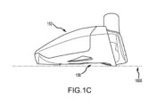
本明細書で規定されたような「フェアウェイタイプのゴルフクラブヘッド」は、固有の寸法範囲によって規定されることが可能な、特定のロフト、容量、及び、寸法を有しているクラブヘッドである。特に、本明細書に開示されたこの発明に関して記載されたようなフェアウェイタイプのクラブヘッドは、以下に規定された範囲内における、ロフト角、容量、長さ、深さ、高さ、及び、フェース高さを含んでいる。以下の明示された範囲は、このフェアウェイタイプのゴルフクラブヘッドを、或るフェアウェイタイプのクラブヘッドに限定する。換言すると、フェアウェイタイプのゴルフクラブヘッドは、ドライバータイプ、ハイブリッドタイプ、アイアンタイプ、又は、パタータイプ、のゴルフクラブヘッドではあり得ない。本明細書で規定されたような、且つ、以下に使用されるような、フェアウェイタイプのゴルフクラブヘッドは、メインボディ、フェースカップ、クラウンインサート、ソールインサート、及び、後部ウェイトから成る群から選択された特徴を有している。図1A及び図1Bは、ボディ102及び打撃フェース104を有しているフェアウェイタイプのゴルフクラブヘッド100を例示している。クラブヘッド100のボディ102は、前端108、前端108の反対側の後端110、クラウン116、クラウン116の反対側のソール118、ヒール120、及び、ヒール120の反対側のトウ122、を含んでいる。ボディ102はさらに、クラウン116とソール118との間に配置されるとともに、クラウン116及びソール118に隣接しているスカート又は終縁128を含んでおり、当該スカートは、クラブヘッド100のヒール120付近からトウ122付近まで連続している。
Where present, the terms "first,""second,""third,""fourth,""fifth," etc. in this specification and claims refer to similar elements. Used to differentiate and not necessarily to describe a particular or chronological order, the terms so used are interchangeable under appropriate circumstances, e.g. It is to be understood that the embodiments described in can operate in sequences other than those illustrated or otherwise described herein. Further, the terms "comprising", "having", and any variations thereof do not necessarily mean that a process, method, system, article, device, or apparatus comprising a list of elements is limited to those elements, and that such a process, method, system, article, device, or apparatus comprising a list of elements is It is intended to encompass non-exclusive inclusion of methods, systems, articles, devices, or apparatus to include other elements not descriptively listed.
II. fairway type club head
A "fairway-type golf club head" as defined herein is a club head having a specific loft, volume, and dimensions that can be defined by a unique dimensional range. . In particular, fairway type club heads as described with respect to the invention disclosed herein have loft angles, volumes, lengths, depths, heights, and faces within the ranges defined below. Includes height. The specified ranges below limit this fairway type golf club head to certain fairway type club heads. In other words, a fairway type golf club head cannot be a driver type, hybrid type, iron type, or putter type golf club head. A fairway type golf club head, as defined herein and as used below, is selected from the group consisting of a main body, a face cup, a crown insert, a sole insert, and a rear weight. It has the following characteristics. 1A and 1B illustrate a fairway-type
本明細書で使用されるフェアウェイタイプのゴルフクラブヘッドは、約35度未満、約34度未満、約33度未満、約32度未満、約31度未満、又は、約30度未満のロフト角を有する。いくつかの実施形態では、フェアウェイタイプのゴルフクラブヘッドのロフト角は、約12度よりも大きく、約13度よりも大きく、約14度よりも大きく、約15度よりも大きく、約16度よりも大きく、約17度よりも大きく、約18度よりも大きく、約19度よりも大きく、又は、約20度よりも大きくすることができる。例えば、他の実施形態では、フェアウェイタイプのロフト角は、14度と35度の間、15度と35度の間、20度と35度の間、又は、12度と30度の間をとることができる。 Fairway-type golf club heads as used herein have a loft angle of less than about 35 degrees, less than about 34 degrees, less than about 33 degrees, less than about 32 degrees, less than about 31 degrees, or less than about 30 degrees. have In some embodiments, the fairway-type golf club head has a loft angle greater than about 12 degrees, greater than about 13 degrees, greater than about 14 degrees, greater than about 15 degrees, and greater than about 16 degrees. can also be greater than about 17 degrees, greater than about 18 degrees, greater than about 19 degrees, or greater than about 20 degrees. For example, in other embodiments, the fairway type loft angle is between 14 degrees and 35 degrees, between 15 degrees and 35 degrees, between 20 degrees and 35 degrees, or between 12 degrees and 30 degrees. be able to.
本明細書で使用されるフェアウェイタイプのクラブは、約170cm3未満、約180cm3未満、約190cm3未満、又は、約200cm3未満の「容量」を有することができる。しかしながら、フェアウェイタイプのクラブの容積は、170cm3未満とすることはできない。いくつかの実施形態では、フェアウェイタイプのクラブヘッドの容量は、約150cm3から200cm3の間、約160cm3から170cm3の間、約160cm3から180cm3の間、又は、約170cm3から190cm3の間の容量とすることができる。フェアウェイタイプのクラブの容量は、200cm3を超えることはできない。1つの例示的な実施形態において、フェアウェイタイプのクラブの容量は、169cm3である。 Fairway-type clubs as used herein can have a "capacity" of less than about 170 cm 3 , less than about 180 cm 3 , less than about 190 cm 3 , or less than about 200 cm 3 . However, the volume of a fairway type club cannot be less than 170 cm3 . In some embodiments, the fairway-type club head has a volume of between about 150 cm and 200 cm , between about 160 cm and 170 cm , between about 160 cm and 180 cm , or between about 170 cm and 190 cm. The capacity can be between 3 and 3 . The capacity of fairway type clubs cannot exceed 200cm3 . In one exemplary embodiment, the fairway type club has a capacity of 169 cm3 .
本明細書に記載されるフェアウェイタイプのゴルフクラブの「フェアウェイタイプのクラブヘッド深さ」160は、フェアウェイタイプのゴルフクラブヘッドの前後寸法によって規定され得る。図5Fを参照すると、フェアウェイタイプのクラブヘッドの深さ160は、Z軸1072に平行な方向に沿ってクラブヘッドの前端108から後端110までの最も遠い範囲として測定され得る。深さ160は、3.00インチから4.00インチの間の範囲とすることができる。いくつかの実施形態において、深さ160は、3.00インチから3.40インチの間、3.25インチから3.40インチの間、3.30インチから3.50インチの間、又は、3.50インチから4.00インチの間の範囲とすることができる。深さ160は、4.00インチを超えることができない。1つの例示的な実施形態において、深さ160は、3.363インチである。
The "fairway type club head depth" 160 of the fairway type golf clubs described herein may be defined by the front-to-back dimensions of the fairway type golf club head. Referring to FIG. 5F, the
本明細書に記載されるフェアウェイタイプのゴルフクラブヘッドの「フェアウェイタイプのゴルフクラブ高さ」164は、フェアウェイタイプのクラブヘッドのクラウン-ソール寸法として規定され得る。図5Eを参照すると、フェアウェイタイプのゴルフクラブヘッド100の高さは、正面図から見たときに、Y軸1062に平行な方向に沿ってクラブヘッド100のクラウン116からソール118までの最も遠い範囲として測定され得る。多くの実施形態において、クラブヘッド100の高さ164は、全米ゴルフ協会(USGA)といったゴルフ管理機関に従って測定することができる。例えば、クラブヘッド100の高さ164は、USGAの、ウッドクラブのクラブヘッドサイズを測定するための手順(USGA-TPX3003、Rev.1.0.0、2003年11月21日)(https://www.usga.org/content/dam/usga/pdf/Equipment/TPX3003-procedure-for-measuring-the-club-head-size-of-wood-clubs.pdfにおいて入手可能)(「ウッドクラブのクラブヘッドサイズを測定するための手順」)に従って決定することができる。高さ164は、1.25インチから2.00インチの間の範囲とすることができる。いくつかの実施形態において、高さ164は、1.25インチから1.50インチの間、1.30インチから1.50インチの間、1.35インチから1.75インチの間、1.45インチから1.80インチの間、又は、1.50インチから2.00インチの間の範囲とすることができる。1つの例示的な実施形態において、クラブヘッド高さ164は、1.424インチである。高さ164は2.00インチよりも大きくない。
The "fairway type golf club height" 164 of the fairway type golf club heads described herein may be defined as the crown-sole dimension of the fairway type club head. Referring to FIG. 5E, the height of the fairway type
本明細書に記載されるフェアウェイタイプのゴルフクラブヘッドの「フェアウェイタイプのクラブヘッド長さ」162は、フェアウェイタイプのクラブヘッドのヒール-トウ寸法として規定され得る。図5Eを参照すると、フェアウェイタイプのゴルフクラブヘッド100の長さ162は、正面図から見たときに、X軸1052に平行な方向に沿ってクラブヘッド100のヒール120からトウ122までの最も遠い範囲として測定され得る。多くの実施形態において、クラブヘッド100の長さ162は、全米ゴルフ協会(USGA)といったゴルフ管理機関に従って測定することができる。例えば、クラブヘッドの長さは、USGAの、ウッドクラブのクラブヘッドサイズを測定するための手順(USGA-TPX3003、Rev.1.0.0、2003年11月21日)(https://www.usga.org/content/dam/usga/pdf/Equipment/TPX3003-procedure-for-measuring-the-club-head-size-of-wood-clubs.pdfにおいて入手可能)(「ウッドクラブのクラブヘッドサイズを測定するための手順(Procedure for Measuring the Club Head Size of Wood Clubs)」)に従って決定することができる。長さ162は、3.00インチから4.60インチの間の範囲とすることができる。いくつかの実施形態において、長さ162は、3.00インチから4.00インチの間、4.00インチから4.40インチの間、4.25インチから4.40インチの間、又は、4.30インチから4.40インチの間の範囲とすることができる。長さは、4.60インチよりも大きくない。1つの例示的な実施形態において、長さ162は、4.384インチである。
The "fairway type club head length" 162 of the fairway type golf club heads described herein may be defined as the heel-toe dimension of the fairway type club head. Referring to FIG. 5E, the
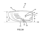
本明細書に記載されるフェアウェイタイプのゴルフクラブヘッドの「フェアウェイタイプのフェース高さ」144は、ロフト面1010に対して平行にクラウン116の近くの打撃フェース外周部142の上端とソール118の近くの打撃フェース外周部142の下端との間で測定される高さとして規定され得る(図3A参照)。これらの実施形態では、打撃フェース外周部142は、曲面が打撃フェース104の膨らみ及び/又は起伏から逸脱するところで、打撃フェース104の外縁に沿って位置することができる。フェース高さ144は、1.00インチから1.50インチの間の範囲とすることができる。いくつかの実施形態において、フェース高さ144は、1.00インチから1.25インチの間、1.00インチから1.15インチの間、1.15インチから1.35インチの間、又は、1.15インチから1.50インチの間の範囲とすることができる。1つの例示的な実施形態において、フェース高さ144は、1.110インチである。
The "fairway-type face height" 144 of the fairway-type golf club heads described herein includes the upper end of the
本明細書に記載されるフェアウェイタイプのゴルフクラブヘッドの「幾何学的中心」140は、打撃フェース外周部の幾何学的中心点である。別のアプローチとして、打撃フェース104の幾何学的中心140は、全米ゴルフ協会(USGA)といったゴルフ管理機関の定義に基づいて配置することができる。例えば、打撃フェースの幾何学的中心は、USGAのゴルフクラブヘッドの可撓性を測定する手順(USGA-TPX3004、Rev.1.0.0,2008年5月1日)(http://www.usga.org/equipment/testing/protocols/Procedure-For-Measuring-The-Flexibility-Of-A-Golf Club-Head/において入手可能)(「可撓性の手順(Flexibility Procedure)」)のセクション6.1に従って決定することができる。
The "geometric center" 140 of the fairway-type golf club head described herein is the geometric center point of the outer circumference of the striking face. As an alternative approach, the
本明細書に記載されるフェアウェイタイプのゴルフクラブヘッドの「幾何学的中心高さ」146は、地表面1000からフェアウェイタイプのクラブヘッドの幾何学的中心までの鉛直方向に測定される高さである。幾何学的中心高さ146は、0.40インチから0.75インチの間の範囲とすることができる。例えば、幾何学的中心高さ146は、0.40インチから0.60インチの間、0.50インチから0.70インチの間、又は、0.65インチから0.75インチの間の範囲とすることができる。1つの例示的な実施形態において、幾何学的中心高さ146は、0.661インチである。
The "geometric center height" 146 of a fairway-type golf club head as described herein is the height measured vertically from the
本明細書に記載したようなフェアウェイタイプのゴルフクラブヘッドの「リーディングエッジ」114は、打撃フェース外周部142の、最もソール方向の部分として識別することができる。例えば、フェアウェイタイプのゴルフクラブヘッドのリーディングエッジ114は、フェアウェイタイプのゴルフクラブヘッドの、打撃フェースの膨らみ及び起伏からソールへの遷移部である。
The "leading edge" 114 of a fairway-type golf club head, such as those described herein, can be identified as the portion of the
本明細書で規定されるとともに以下に使用されるような、フェアウェイタイプのゴルフクラブヘッドの「力線インパクト点」(又はFLIP)190は、打撃フェース104上の点であり、フェアウェイタイプのゴルフクラブのストロークの力が、この点においてゴルフボールに最も効率的に伝達される。
As defined herein and as used below, a "line of force impact point" (or FLIP) 190 of a fairway-type golf club head is a point on the
本明細書に記載されるフェアウェイタイプのゴルフクラブヘッドの「FLIP高さ」192は、地表面1000からフェアウェイタイプのクラブヘッドのFLIP190までの鉛直方向に測定される高さとすることができる。FLIP高さ192は、0.55インチから0.75インチの間の範囲である。FLIP高さ192は、約0.55インチ、約0.56インチ、約0.57インチ、約0.58インチ、約0.59インチ、約0.60インチ、約0.61インチ、約0.62インチ、約0.63インチ、約0.64インチ、約0.65インチ、約0.66インチ、約0.67インチ、約0.68インチ、約0.69インチ、約0.70インチ、約0.71インチ、約0.72インチ、約0.73インチ、約0.74インチ、又は、約0.75インチとすることができる。
The "FLIP height" 192 of a fairway-type golf club head described herein may be the height measured in the vertical direction from the
本明細書で規定されるとともに以下に使用されるような、フェアウェイタイプのゴルフクラブヘッドの「力線インパクト点軸」(又はFLIP軸)195は、FLIP190において生じるとともに、打撃フェース104から後方に且つFLIP190において打撃フェース104に対して垂直に延びる、軸である。
As defined herein and as used below, the "line of force impact point axis" (or FLIP axis) 195 of a fairway-type golf club head occurs at the
本明細書で規定されたようなフェアウェイタイプのゴルフクラブヘッドの「外周部」112は、クラブヘッド上側部分152からクラブヘッド下側部分156への遷移部を備えている。外周部112は、ゴルフクラブヘッドの周囲の一連の点によって規定されており、当該点の各々は、フェアウェイタイプのゴルフクラブヘッド100がアドレス位置にあるときに、地表面1000に対して垂直に描かれた線に対する接線を有している。フェアウェイタイプのゴルフクラブヘッド100の外周部は、全てのこれらの点の集合である。フェアウェイタイプのゴルフクラブヘッド100の上側部分152は、フェアウェイタイプのゴルフクラブヘッド100の外周部よりも上における、打撃フェース104を除いた、当該フェアウェイタイプのゴルフクラブヘッドの部分として規定されている。フェアウェイタイプのゴルフクラブヘッド100の下側部分156は、フェアウェイタイプのゴルフクラブヘッド100の外周部よりも下における、打撃フェース104を除いた、当該フェアウェイタイプのゴルフクラブヘッドの部分として規定されている。
The "periphery" 112 of a fairway-type golf club head as defined herein includes a transition from a club head
本明細書で規定されるとともに以下に使用されるようなフェアウェイタイプのゴルフクラブヘッドの「メインボディ」202は、クラウンインサート、フェースカップ、ソールインサート、及び、後部ウェイトが取り付けられてフェアウェイタイプのゴルフクラブヘッド100を形成する、取り付け部及び機械的構造を提供する。図2A~図2Cを参照すると、フェアウェイタイプのゴルフクラブヘッドのメインボディ202は、メインボディ前部分214、メインボディ後部分212、メインボディトウ部分222、メインボディヒール部分220、ソール218、及び、クラウンリターン216を備えている。本明細書で規定されるとともに以下に使用されるようなメインボディヒール部分220は、ヒールリターン224、ヒール打撃フェース部分226、及び、ホーゼル230を備えている。本明細書で規定されるとともに以下に使用されるようなメインボディ前部分214は、前窓210、メインボディトウ部分222、ヒールリターン224、ヒール打撃フェース部分226、ソール218、及び、クラウンリターン216を備えている。
A "main body" 202 of a fairway-type golf club head, as defined herein and used below, includes a crown insert, a face cup, a sole insert, and a rear weight attached to form a fairway-type golf club head. The attachment and mechanical structure that forms the
本明細書で規定されるとともに以下に使用されるようなフェアウェイタイプのゴルフクラブヘッドの「ソール」218は、メインボディの、下側の、地表方向に向いている部分であり、ソール外側表面219、ソールトウ方向部分211、ソールヒール方向部分215、及び、ソール中央部分221を備えている。ソール218は、ソールインサート凹部240を備えている。ソール218はさらに、後部ウェイト凹部250を備えている。ソール中央部分221は、ヒール-トウ方向において地表面1000に対して概して平行である。ソールトウ方向部分211は、クラウン方向に沿って上方に、ソール中央部分221から湾曲している。ソールヒール方向部分215は、クラウン方向に沿って上方に、ソール中央部分221から湾曲している。
The "sole" 218 of a fairway-type golf club head, as defined herein and as used below, is the lower, ground-facing portion of the main body, the sole
本明細書で規定されるとともに以下に使用されるようなフェアウェイタイプのゴルフクラブヘッドの「ソールインサート凹部」240は、その最も外側の表面がソール外側表面219から内方に向かっている窪みである。ソールインサート凹部240は、その占有範囲の大部分がソール中央部分221内にある。ソールインサート凹部240はさらに、ソールインサート凹部床241、ソールインサート締結具凹部243、ソールインサート締結具窓247、及び、ソールインサート前方質量パッド凹部248を備えている。質量パッド凹部248は、ソールインサート凹部240の異なる位置に配置することができる。ソールインサートは、ソール外側表面219から内方に測定されたソールインサート凹部床深さ242を有している。ソールインサート前方質量パッド凹部248はさらに、ソールインサート凹部床241から内方に測定された前方質量パッド凹部深さ249(図示せず)を有している。質量パッド凹部深さ249は、ソールインサート厚さ448に対応している。ソール218はさらに、シャフト取り付け部凹部290及びシャフト締結具窓292を備えている。
A "sole insert recess" 240 of a fairway-type golf club head, as defined herein and used below, is a recess with its outermost surface facing inwardly from the sole
本明細書で規定されるとともに以下に使用されるようなフェアウェイタイプのゴルフクラブヘッドの「ソール後部ウェイト凹部」250は、後部ウェイトを受容するように構成された、ソール218の後部分における内方凹みであって、近傍のソール外側表面219から内方に測定されたソール後部ウェイト凹部深さ251を有している。ソール後部ウェイト凹部250は、ウェイト凹部後部レッジ252を備えており、ウェイト凹部後部レッジ252は、近傍のソール外側表面219から内方に測定されるとともに、ウェイト凹部深さ251未満である、レッジ深さ254を有している。後部ウェイト凹部250は、後部ウェイト締結具窓255を備えている。
A "sole rear weight recess" 250 of a fairway-type golf club head, as defined herein and as used below, is an inward portion of the rear portion of the sole 218 that is configured to receive a rear weight. The recess has a sole rear
本明細書で規定されるとともに以下に使用されるようなフェアウェイタイプのゴルフクラブヘッドの「ソールインサート」430は、ソールインサート凹部250内に受容されるように構成された高密度インサートである。図7Aを参照すると、ソールインサート430は、前縁454、後縁456、ヒール側縁458、及び、トウ側縁460、を有している外周部420と、頂表面462と、底表面464と、を備えている。ソールインサート430は、頂表面462がソールインサート凹部床241に接触するようにソールインサート凹部240内に受容されるように構成されており、底表面464が、ソール外側表面219の一部分を成している。ソールインサート430は、ソール外側表面219の実質的部分を規定するように、相対的に大きいことが可能である。ソールインサート外周部420は、長さ、幅、及び、厚さといったソールインサート430の寸法を規定するために使用される。
The “sole insert” 430 of a fairway-type golf club head, as defined herein and used below, is a high density insert configured to be received within the
本明細書で規定されるとともに以下に使用されるようなフェアウェイタイプのゴルフクラブヘッドの「ソールインサート深さ」446は、ソールインサートにわたって前後方向において前縁454から後縁456まで測定されている(図7B参照)。ソールインサート深さ446は、ソールインサート430にわたってヒール-トウ方向において一様であることが可能である。代替として、深さ446は、ソールインサート430にわたってヒール-トウ方向において変動することが可能である。ソールインサート深さ446は、0.5インチから2.00インチの間の範囲とすることができる。深さ446は、1.3インチよりも大きく、1.4インチよりも大きく、1.5インチよりも大きく、1.6インチよりも大きく、1.7インチよりも大きく、又は、1.8インチよりも大きくすることができる。代替として、深さ446は、0.5インチから2.0インチの間、0.6インチから1.8インチの間、1.3インチから1.6インチの間、1.5インチから1.8インチの間、1.7インチから1.8インチの間、又は、1.7インチから2.0インチの間、の範囲とすることができる。1つの例示的な実施形態において、最大深さ446は1.76インチである。ソールインサート深さ446は、メインボディソール218の占有場所内に留まった状態でソール118付近に大きな質量をもたらしてCGを下げるように選択されている。
The "sole insert depth" 446 of a fairway-type golf club head, as defined herein and used below, is measured across the sole insert in the fore-and-aft direction from the
本明細書で規定されるとともに以下に使用されるようなフェアウェイタイプのゴルフクラブヘッドの「ソールインサート長さ」447は、ソールインサートヒール側縁458からソールインサートトウ側縁460まで測定されている(図7B参照)。ソールインサート長さ447は、ソールインサート430にわたって前後方向において一様であることが可能である。代替的に、長さ447は、ソールインサート430にわたって前後方向において変動することが可能である。ソールインサート長さ447は、1.00インチから4.00インチの間の範囲とすることができる。長さ447は、2.2インチよりも大きく、2.3インチよりも大きく、2.4インチよりも大きく、2.5インチよりも大きく、2.6インチよりも大きく、又は、2.7インチよりも大きくすることができる。代替として、長さ447は、1.0インチから2.6インチの間、2.2インチから2.6インチの間、2.4インチから2.7インチの間、2.5インチから2.8インチの間、又は、2.7インチから3.0インチの間の範囲とすることができる。1つの例示的な実施形態において、最大長さ447は、2.54インチである。
The "sole insert length" 447 of a fairway-type golf club head, as defined herein and used below, is measured from the sole
本明細書で規定されるとともに以下に使用されるようなフェアウェイタイプのゴルフクラブヘッドの「ソールインサート厚さ」448は、ソールインサート頂表面462からソールインサート底表面464まで測定されている(図7C参照)。ソールインサート430を、異なる部分にわたって薄肉化又は厚肉化させて、クラブヘッドのCG172のバランスを取ることができる。厚さ448は、ソールインサート430にわたって前後方向及び/又はヒール-トウ方向において変動することが可能である。代替として、ソールインサート厚さ448は、ソールインサート430にわたって前後方向及び/又はヒール-トウ方向において一様であることが可能である。ソールインサート厚さ448は、0.050インチから0.30インチの間の範囲とすることができる。厚さ448は、0.050インチよりも大きく、0.055インチよりも大きく、0.060インチよりも大きく、0.065インチよりも大きく、0.070インチよりも大きく、0.075インチよりも大きく、0.080インチよりも大きく、0.085インチよりも大きく、0.090インチよりも大きく、0.095インチよりも大きく、0.10インチよりも大きく、0.11インチよりも大きく、0.12インチよりも大きく、0.13インチよりも大きく、0.14インチよりも大きく、0.15インチよりも大きく、0.16インチよりも大きく、0.17インチよりも大きく、0.18インチよりも大きく、0.19インチよりも大きく、0.20インチよりも大きく、0.21インチよりも大きく、0.22インチよりも大きく、0.23インチよりも大きく、0.24インチよりも大きく、0.25インチよりも大きく、0.26インチよりも大きく、0.27インチよりも大きく、0.28インチよりも大きく、0.29インチよりも大きく、又は、0.30インチよりも大きくすることができる。代替として、厚さ448は、0.050インチから0.10インチの間、0.075インチから0.20インチの間、又は、0.075インチから0.20インチの間の範囲とすることができる。ソールインサート厚さ448は、前後方向及びヒールートウ方向におけるクラブヘッドCG172のバランスを保ちながら、ソール118の近くの実質的な質量を提供するために選択される。
The "sole insert thickness" 448 of a fairway-type golf club head, as defined herein and used below, is measured from the sole insert
本明細書で規定されるとともに以下に使用されるようなフェアウェイタイプのゴルフクラブヘッドの「クラウン窓」234は、メインボディトウ部分222、メインボディヒール部分220、ソール218、クラウンリターン216、及び、メインボディ後部分212により取り囲まれるとともに規定された、上側頂側開口部を備えている。クラウン窓234は、トウ凹み260及びヒール凹み262を備えており、トウ凹み260及びヒール凹み262の各々は、クラウン窓234を、フェアウェイタイプのゴルフクラブヘッド100の上側部分からフェアウェイタイプのゴルフクラブヘッド100の下側部分に向けて、遷移部を越えて延ばす。クラウン窓外周部はさらに、クラウンフランジ217、後部フランジ228、トウクラウン窓トウ凹みフランジ261、及び、クラウン窓ヒール凹みフランジ263を備えている。クラウンフランジ217は、クラウンリターン216から内方に凹んでおり、上向きに配向された外側表面を有している。後部フランジ228は、メインボディ後部分後縁213から内方に凹んでおり、後部に向けて且つ上向きに配向された外側表面を有している。トウ凹みフランジ261は、トウ部分222の外側表面及びソール218の外側表面から内方に凹んでいる。トウ凹みフランジ261の外側表面は、トウ方向及び下向きに配向されている。ヒール凹みフランジ263は、ヒール部分220及びソール218から内方に凹んでいる。ヒール凹みフランジ263の外側表面は、ヒール方向及び下向きに配向されている。クラウンフランジ217、後部フランジ228、トウ凹みフランジ261、及び、ヒール凹みフランジ263の外側表面はさらに、複数のフランジスペーサ270を備えている。フランジスペーサ270は、各フランジの外側表面から外方に延びており、クラウンインサート800の、クラウン窓234内への接着性取り付けが行われたときに、間隙を設ける。
The "crown window" 234 of a fairway-type golf club head, as defined herein and as used below, includes a main
本明細書で規定されるとともに以下に使用されるようなフェアウェイタイプのゴルフクラブヘッドの「接合深さ」は、クラウンフランジ217、後部フランジ228、トウフランジ261、及び、ヒールフランジ263が、メインボディ202の最も外側の表面から内方に凹んでいる距離である。接合深さは、メインボディ202の外側表面からそれぞれのフランジ217、228、261、及び、263の外側表面まで測定されている。接合深さは、0.010インチから0.050インチの間の範囲とすることができる。いくつかの実施形態において、接合深さは、0.010インチから0.030インチの間、0.020インチから0.040インチの間、又は、0.025インチから0.050インチの間である。1つの例示的な実施形態において、接合深さは、0.030インチである。
The "joint depth" of a fairway type golf club head, as defined herein and used below, means that the
本明細書で規定されるとともに以下に使用されるようなフェアウェイタイプのゴルフクラブヘッドの「前窓」210は、メインボディトウ部分222、ヒールリターン224、ヒール打撃フェース部分226、ソール218、及び、クラウンリターン216によって取り囲まれるとともに規定された、前方開口部である。前窓210は、ロフト面1010に対して概して平行に、前窓面280を規定する。前窓面280は、前窓面オフセット距離282だけ、ロフト面1010から後方にオフセットされている。
The "front window" 210 of a fairway-type golf club head, as defined herein and as used below, includes a main
本明細書で規定されるとともに以下に使用されるようなフェアウェイタイプのゴルフクラブヘッドの「後部ウェイト支持構造」299は、厚肉化されているとともに、当該フェアウェイタイプのゴルフクラブヘッドの遠く後方の部分に配置された、ソール中央部分221のセクションである。図2Aから図2Cを参照すると、支持構造299は、後部フランジ228と、後部ウェイト凹部250と、後部ウェイト凹部250の周囲の支持素材と、を備えている。支持構造は、前後に測定された構造長さ283を有しており、1.50インチから0.75インチの範囲内にある。支持構造長さ283は、フェアウェイタイプのゴルフクラブヘッド上の、最も後方の外側の点から、後部ウェイト凹部250の最も前方の内壁まで測定されている。支持構造299は、ゴルフクラブヘッドの底部外側表面から後部フランジ228の最も上側の点まで測定された支持構造高さ293を有している。支持構造高さ293は、0.30インチから1.50インチの範囲内であることが可能である。近傍のソール外側表面219から内方に測定されたレッジ深さ254は、0.05インチから0.15インチの範囲内であることが可能である。ウェイト凹部後部レッジ252は、フェアウェイタイプのゴルフクラブヘッドの後部に対して、及び、フェアウェイタイプのゴルフクラブヘッドの底部に対して、開放している。ウェイト凹部後部レッジ252は、後部ウェイト後方突起を受容するように構成されている。後部フランジ228は、後部フランジ高さ291と、後部フランジ228のトウ側からヒール側まで測定された後部フランジ長さと、を有している。後部フランジ228は、クラウンインサート800の最も後ろの部分を受容するように構成されており、それにより、クラウンインサート800の下側後縁が支持されるようにする。そのため、後部フランジ228は、フェアウェイタイプのゴルフクラブヘッド100の後部外側表面から内方にオフセットされて、支持構造インセット284を形成している。支持構造インセット284は、この位置におけるクラウンインサート厚さに対応する0.01インチから0.25インチの範囲内にあるインセット深さ285に加え、接着性ボンドラインについてのボンドライン深さを有している。支持構造高さ293が、後部ウェイト凹部深さ251、後部ウェイト締結具窓255の高さ、及び、後部フランジ高さ291を包含していなければならないが故に、支持構造229は、相対的に大きな支持構造質量を有している。支持構造質量は、0.1グラムから50.0グラムの範囲内にある。さらに、後部ウェイト1111が後部ウェイト凹部250内に受容されているとき、支持構造229及びウェイトの質量は、25グラム以上である。
The "rear weight support structure" 299 of a fairway-type golf club head, as defined herein and used below, is thickened and located far to the rear of the fairway-type golf club head. A section of the sole
本明細書で規定されるとともに以下に使用されるようなフェアウェイタイプのゴルフクラブヘッドの「クラウンインサート」800は、メインボディ202のクラウン窓234内に受容されるように構成された軽量構成要素である。図4A~図4Cを参照すると、クラウンインサート800は、クラブヘッドのソール118に向けて延び、トウ凹み260を被覆するとともに、トウ凹みフランジ261を覆ってクラブヘッド外側表面の一部分を成す。同様に、クラウンインサートヒールウィング812は、クラブヘッドのソール118に向けて延び、ヒール凹み262を被覆するとともに、ヒール凹みフランジ263を覆ってクラブヘッド外側表面の一部分を成す。クラウンインサート上側部分834は、フェアウェイタイプのゴルフクラブヘッドのクラウン116の一部分を成し、クラウンフランジ217に重なる。クラウンインサート後部ウィング816は、フェアウェイタイプのゴルフクラブヘッド100の後部110において、クラブヘッドのソール118に向けて下方に延びて、後部フランジ228を覆ってクラブヘッド外側表面の一部分を成す。クラウンインサート上側部分834は、フェアウェイタイプのゴルフクラブヘッドの外周部よりも上に配置された、クラウンインサートの部分である。クラウンインサート下側部分836は、フェアウェイタイプのゴルフクラブヘッドの外周部112よりも下に配置された、クラウンインサート800の部分である。
A “crown insert” 800 of a fairway-type golf club head, as defined herein and used below, is a lightweight component configured to be received within the
本明細書で規定されるとともに以下に使用されるようなフェアウェイタイプのゴルフクラブヘッドの「フェースカップ」300は、メインボディ前窓210に永続的に固定されるように構成された構成要素である。図1C、図2A、図2B、及び、図3A~図3Cを参照すると、フェースカップ300は、フェースカップ前部分310、フェースカップトウ部分311、フェースカップ打撃フェース部分304、フェースカップクラウンリターン316、フェースカップソールリターン318、及び、フェースカップヒール部分315を備えている。フェースカップ300は、メインボディ前窓210内に受容されるとともに、メインボディ前窓210に永続的に固定されて、ゴルフクラブヘッド100の前部108を形成する、ように構成されている。フェースカップ300がメインボディに固定されると、メインボディ打撃フェース部分226及びフェースカップ打撃フェース部分304が組み合わさって、フェアウェイタイプのゴルフクラブヘッドの打撃フェース104を形成する。フェースカップ300のクラウンリターン316、フェースカップソールリターン318、及び、フェースカップトウ部分311は、フェースカップ打撃フェース部分304を取り囲んでいる。フェースカップ300は、フェースカップ後部外周部を成すフェースカップ後縁381を有している。フェースカップ後縁381は、フェースカップ300の後方縁の全体を包含しており、フェースカップ300のヒール方向縁も包含している。フェースカップ後縁381は、フェースカップ300がメインボディ100に固定されたときにメインボディ前縁281に当接するように構成されている。フェースカップクラウンリターン316上の最も後ろの点、及び、フェースカップソールリターン318上の最も後ろの点は、フェースカップ後面380を規定する。フェースカップ後面380は、ロフト面1010に対して平行である。
The "face cup" 300 of a fairway-type golf club head, as defined herein and as used below, is a component configured to be permanently secured to the main
本明細書で規定されるとともに以下に使用されるようなフェアウェイタイプのゴルフクラブヘッドの「打撃フェース厚さ」330は、打撃前表面から打撃フェース後表面まで測定されている。図3Cを参照すると、打撃フェース厚さ330は、トウ-ヒール方向及びクラウン-ソール方向において変動することが可能である。打撃フェース厚さ330は、0.020インチから0.050インチの範囲内にあることが可能である。
The "striking face thickness" 330 of a fairway-type golf club head, as defined herein and used below, is measured from the front striking surface to the rear striking face surface. Referring to FIG. 3C, the
本明細書で規定されるとともに以下に使用されるようなフェアウェイタイプのゴルフクラブヘッドの「打撃フェース面積」は、打撃フェースの総表面積である。打撃フェース面積は、2.00in2から3.00in2の範囲とすることができる。打撃フェース面積は、約2.00in2、約2.05in2、約2.10in2、約2.15in2、約2.20in2、約2.25in2、約2.30in2、約2.35イin2、約2.40in2、約2.45in2、約2.50in2、約2.55in2、約2.60in2、約2.65in2、約2.70in2、約2.75in2、約2.80in2、約2.85in2、約2.90in2、約2.95in2、又は、約3.00in2とすることができる。1つの例示的な実施形態において、打撃フェース面積は、約2.345in2である。 The "striking face area" of a fairway-type golf club head, as defined herein and used below, is the total surface area of the striking face. The striking face area can range from 2.00 in 2 to 3.00 in 2 . The hitting face area is approximately 2.00in 2 , approximately 2.05in 2 , approximately 2.10in 2 , approximately 2.15in 2 , approximately 2.20in 2 , approximately 2.25in 2 , approximately 2.30in 2 , approximately 2. 35in2 , about 2.40in2 , about 2.45in2 , about 2.50in2 , about 2.55in2 , about 2.60in2 , about 2.65in2 , about 2.70in2 , about 2. It can be 75 in2 , about 2.80 in2 , about 2.85 in2 , about 2.90 in2 , about 2.95 in2 , or about 3.00 in2 . In one exemplary embodiment, the striking face area is approximately 2.345 in 2 .
本明細書で規定されるとともに以下に使用されるようなフェアウェイタイプのゴルフクラブヘッドの「後部ウェイトアセンブリ」1100は、後部ウェイトアセンブリ1100を構成している、取り外し可能な、調節可能な、又は、相互交換可能なウェイトアセンブリであって、後部ウェイトアセンブリ1100は、後部ウェイト1111、後部ウェイトねじ山付き締結具1160、及び、後部ウェイト座金1170を備えている。図2A~図2C及び図6Aを参照すると、後部ウェイト凹部250は、後部ウェイト支持構造299により包含されている。
A "rear weight assembly" 1100 of a fairway-type golf club head, as defined herein and used below, comprises a removable, adjustable, or
本明細書で規定されるとともに以下に使用されるようなフェアウェイタイプのゴルフクラブヘッドの「後部ウェイト」1111は、後部ウェイト凹部250内に少なくとも部分的に受容されるように構成された、着脱可能なウェイト構成要素である。図5D、図6A、及び、図6Bを参照すると、後部ウェイトは、後部ウェイ高さ1112、後部ウェイト幅1114(図示せず)、後部ウェイト長さ1116、後部ウェイト頂表面1120、後部ウェイト底表面1124、当該頂表面と当該底表面との間の後部ウェイト外周部表面1128、後部ウェイト突起1130、頂部座金凹部1140、後部ウェイト締結具窓1150、及び、締結具窓1150内における後部ウェイト窓肩部1154、を備えている。ねじ山付き締結具1160は、ねじ山付き締結具1160の頭部が窓肩部1154に当接するまで、底表面1124から締結具窓1150内へ上方に挿入される。ねじ山付き締結具1160の一部分は、頂表面1120を越えて延びる。ウェイト座金1170は、ねじ山付き締結具1160の真上に受容され、ウェイト座金1170は、頂部座金凹部1140内においても受容されている。この後部ウェイトアセンブリは、一旦完全に組み付けられると、後部ウェイト凹部250内に受容されることが可能であり、ねじ山付き締結具1160は、後部ウェイト締結具窓255内に螺合可能に受容される。後部ウェイト底表面1124は、フェアウェイタイプのゴルフクラブヘッドの底外部に露出している。後部ウェイト突起1130は、フェアウェイタイプのゴルフクラブヘッドの底外部及び後外部の両方に露出している。
III.座標系
A "rear weight" 1111 of a fairway-type golf club head as defined herein and as used below is a removable member configured to be at least partially received within the
III. Coordinate system
本発明を記述する様々な重心、FLIP軸、及び、フェアウェイタイプのクラブヘッド寸法をもたらすために、フェアウェイタイプのクラブヘッドに適用される2つの座標系が以下に記載される。 Two coordinate systems that apply to fairway type club heads are described below to provide various center of gravity, FLIP axis, and fairway type club head dimensions that describe the present invention.
本明細書に記載されるフェアウェイタイプのゴルフクラブヘッドの「XYZ」座標系は、打撃フェース104の幾何学的中心140に基づいている。本明細書に記載されるフェアウェイタイプのクラブヘッド寸法は、以下に規定するような座標系に基づいて測定することができる。打撃フェース104の幾何学的中心140は、打撃フェース104の幾何学的中心140に位置付けられた原点を有している座標系を規定している。この座標系は、X軸1052、Y軸1062、及び、Z軸1072を有している。X軸1052は、打撃フェース104の幾何学的中心140を通って、フェアウェイタイプのクラブヘッド100のヒール120からトウ122への方向に延びる。Y軸1062は、打撃フェース104の幾何学的中心140を通って、フェアウェイタイプのクラブヘッド100のクラウン116からソール118への方向に延びる。Y軸1062は、X軸1052に対して垂直に延びる。Z軸1072は、打撃フェース104の幾何学的中心140を通って、フェアウェイタイプのクラブヘッド100の前端108から後端110への方向に延びる。Z軸1072は、X軸1052及びY軸1062に対して垂直に延びる。
The "XYZ" coordinate system of the fairway-type golf club head described herein is based on the
本明細書に記載されるフェアウェイタイプのゴルフクラブヘッドのXYZ座標系は、X軸1052及びY軸1062を通って延びるXY面を規定する。この座標系は、X軸1052及びZ軸1072を通って延びるXZ面を規定する。この座標系はさらに、Y軸1062及びZ軸1072を通って延びるYZ面を規定する。XY面、XZ面、及び、YZ面は全て、互いに対して垂直であるとともに、打撃フェース104の幾何学的中心140に位置付けられた座標系の原点において交差する。XY面は、ホーゼル軸132に対して平行に延びており、フェアウェイタイプのクラブヘッド100の、ロフト面1010からのロフト角に対応する角度において位置決めされている。これら又は他の実施形態において、フェアウェイタイプのクラブヘッド100は、打撃フェース104をXY面に対して垂直な方向から見たときに、正面図(図1B)から視認可能である。さらに、これら又は他の実施形態において、フェアウェイタイプのクラブヘッド100は、ヒール120をYZ面に対して垂直な方向から見たときに、側面図又は側面断面図(図1A)から視認可能である。
The XYZ coordinate system for fairway-type golf club heads described herein defines an XY plane that extends through an
本明細書に記載されるフェアウェイタイプのゴルフクラブヘッドのxyz座標系は、フェアウェイタイプのクラブヘッドCG172の重心に基づいている。xyz座標系は、幾何学的中心140に基づくXYZ座標系とは異なっている。フェアウェイタイプのクラブヘッドCG172は、x軸1050、y軸1060、及び、z軸1070を有している座標系の原点を規定する。y軸1060は、ヘッドCG172を通って、フェアウェイタイプのクラブヘッド100のクラウン116からソール118への方向に延びる。x軸1050は、ヘッドCG172を通ってヒール120からトウ122へ、正面図から見ると、y軸1060に対して垂直に延び、XY面に平行に延びる。z軸1070は、ヘッドCG172を通って前端108から後端110へ、x軸1050及びy軸1060に対して垂直に延びる。多くの実施形態において、x軸1050は、ヘッドCG172を通ってヒール120からトウ122へ、X軸1052に平行に延びる。y軸1060は、ヘッドCG172を通ってクラウン116からソール118へ、Y軸1062に平行に延びる。z軸1070は、ヘッドCG172を通って前端108から後端110へ、Z軸1072に平行に延びる。
The xyz coordinate system of the fairway type golf club head described herein is based on the center of gravity of the fairway type club head CG172. The xyz coordinate system is different from the XYZ coordinate system based on the
本明細書に記載されるフェアウェイタイプのゴルフクラブヘッドの「ロフト面」1010は、打撃フェース104の幾何学的中心140に接する面である。ロフト面1010は、地表面1000に対するロフト角を形成する。
IV.CGの位置を決定する方法
The “loft plane” 1010 of the fairway-type golf club heads described herein is the plane tangent to the
IV. How to determine CG position
フェアウェイタイプのクラブヘッドのCG172及びソールインサートのCG472については、異なるフェアウェイタイプのゴルフクラブヘッドの構成要素の位置を基準として記述することができる。以下に記載されるような、望ましいCG172及び472の位置を記述するために、いくつかの方法が創出されている。フェアウェイタイプのクラブヘッドのCG172及びソールインサートのCG472は、これらの方法のいずれかの組み合わせを使用して記述することができる。各方法は、CG172が最適に配置されるであろう、フェアウェイタイプのクラブヘッド100内の「仮想容量」又は容量を確立している。図5A~図5D及び図8A~図8Eは、フェアウェイタイプのクラブヘッド100内における当該容量を、二次元面積として例示している(縮尺通りに描かず)。二次元面積は、フェアウェイタイプのクラブヘッド内の三次元容量(図示せず)として理想化することができる。CG172及び472は、明示された面積又は明示された容量に制限することができる。以下に記載するオフセットは、規定点からの、いずれかの方向における絶対値又はオフセットであり得る。例えば、CGX1は、ヒール方向又はトウ方向の方向における、Y軸1062からのオフセットであり得る。
Fairway type
本明細書で規定されるとともに以下に使用されるような、CGの位置172及び472を決定するための「幾何学的中心方法」について、フェースの幾何学的中心140において生じるXYZ座標系を基準として説明する。幾何学的中心方法は、フェアウェイタイプのクラブヘッドのCG172及びソールインサートのCG472を配置するために使用することができる。フェアウェイタイプのクラブヘッドのCG172は、オフセット(CGX1)173、オフセット(CGY1)176、及び、オフセット(CGZ1)174において配置されている。ソールインサートのCG472は、オフセット(CGX1)473、オフセット(CGY1)476、及び、オフセット(CGZ1)474において配置されている。フェアウェイタイプのクラブヘッドのCG172及びソールインサートのCG472は、この方法を使用して同様に記述することが可能であるが、フェアウェイタイプのクラブヘッドのCG172について得られた値と、ソールインサートのCG472について得られた値とは、同じであること、又は、同じではないこと、があり得る。換言すると、CGZ1174、CGY1176、及び、CGX1173は、フェアウェイタイプのクラブヘッドのCG172に関連性を有しており、CGZ1474、CGY1476、及び、CGX1473は、ソールインサートのCG472に関連性を有している。図5A及び図8Aを参照すると、CG172及び472は、幾何学的中心140からZ軸1072に対して平行に、後方に測定されたオフセット(CGZ1)174及び474において配置されている。CG172及び472はさらに、CG172及び472からZ軸1072に対して垂直に測定されたオフセット(CGY1)176及び476において配置されている。CG172及び472は、幾何学的中心140よりも上又は下にあることが可能である。換言すると、CGY1は、Z軸1072からの絶対値である。CGはさらに、幾何学的中心140からX軸1052に対して平行に測定されたオフセット(CGX1)173及び473(図示せず)において配置されている。CG172及び472は、幾何学的中心140を基準としてヒール方向又はトウ方向にあることが可能である。換言すると、CGX1173及び473は、Y軸1062からの絶対値である。幾何学的中心方法を使用して、最小及び最大のCGX1値、CGY1値、及び、CGZ1値により、フェアウェイタイプのクラブヘッドのCG172及びソールインサートのCG472の周囲に、別個の仮想ボックスを規定することができる。CGX1173及び473は、ヒール-トウ方向においてボックスを規定することができ、CGY1176及び476は、クラウン-ソール方向においてボックスを規定することができ、CGZ1174及び474は、前後方向においてボックスを規定することができる。仮想ボックスは、最適なCG172及び472の値の範囲を規定することができる。フェアウェイタイプのクラブヘッドのCG172の周囲に描かれた仮想ボックスは、ソールインサートのCG472の周囲に描かれた仮想ボックスよりも、クラウン及び打撃フェースに近接して配置することができる。
For the "geometric center method" for determining
本明細書で規定されるとともに以下に使用されるような、CGの位置172及び472を決定するための「リーディングエッジ方法」について、フェアウェイタイプのクラブヘッドのリーディングエッジ114を基準として説明する。リーディングエッジ方法は、フェアウェイタイプのクラブヘッドのCG172及びソールインサートのCG472を配置するために使用することができる。フェアウェイタイプのクラブヘッドのCG172は、オフセット(CGX1)173、オフセット(CGY2)180、及び、オフセット(CGZ2)181において配置されている。ソールインサートのCG472は、オフセット(CGX1)473、オフセット(CGY2)480、及び、オフセット(CGZ2)481において配置されている。フェアウェイタイプのクラブヘッドのCG172及びソールインサートのCG472は、この方法を使用して同様に記述することが可能であるが、フェアウェイタイプのクラブヘッドのCG172について得られた値と、ソールインサートのCG472について得られた値とは、同じであること、又は、同じではないこと、があり得る。換言すると、CGZ2181、CGY2180、及び、CGX1173は、フェアウェイタイプのクラブヘッドのCG172に関連性を有しており、CGZ2481、CGY2480、及び、CGX1473は、ソールインサートのCG472に関連性を有している。図5B及び図8Bを参照すると、CG172及び472は、地表面1000に対して垂直に測定されたオフセット(CGY2)180及び480において配置されている。CG172及び472はさらに、リーディングエッジ114から地表面1000に対して平行に、後方にCG172及び472まで測定されたオフセット(CGZ2)181及び481において配置されている。CGはさらに、幾何学的中心140からX軸1052に対して平行に測定されたオフセット(CGX1)173及び473(図示せず)において配置されている。CG172及び472は、幾何学的中心140を基準としてヒール方向又はトウ方向にあることが可能である。換言すると、CGX1173及び473は、Y軸1062からの絶対値である。フェアウェイタイプのクラブヘッドを前部から視認すると、リーディングエッジは、Y軸1062に沿った点として理想化される。したがって、CG172及び472の、X軸1062方向における位置は、幾何学的中心140に基づいている。リーディングエッジ方法を使用して、最小及び最大のCGX1値、CGY2値、及び、CGZ2値により、フェアウェイタイプのクラブヘッドのCG172及びソールインサートのCG472の周囲に、別個の仮想ボックスを規定することができる。CGX1173及び473は、ヒール-トウ方向においてボックスを規定することができ、CGY2180及び480は、クラウン-ソール方向においてボックスを規定することができ、CGZ2181及び481は、前後方向においてボックスを規定することができる。仮想ボックスは、最適なCG172及び472の値の範囲を規定することができる。フェアウェイタイプのクラブヘッドのCG172の周囲に描かれた仮想ボックスは、ソールインサートのCG472の周囲に描かれた仮想ボックスよりも、クラウン及び打撃フェースに近接して配置することができる。
The "leading edge method" for determining
本明細書で規定されるとともに以下に使用されるような、CGの位置172及び472を決定する「出口点(exit point)方法」について、FLIP軸出口点196を基準として説明する。出口点方法は、フェアウェイタイプのクラブヘッドのCG172及びソールインサートのCG472を配置するために使用することができる。フェアウェイタイプのクラブヘッドのCG172は、オフセット(CGX2)179、オフセット(CGY2)180、及び、オフセット(CGZ3)187において配置されている。ソールインサートのCG472は、オフセット(CGX2)479、オフセット(CGY2)480、及び、オフセット(CGZ3)487において配置されている。フェアウェイタイプのクラブヘッドのCG172及びソールインサートのCG472は、この方法を使用して同様に記述することが可能であるが、フェアウェイタイプのクラブヘッドのCG172について得られた値と、ソールインサートのCG472について得られた値とは、同じであること、又は、同じではないこと、があり得る。換言すると、CGZ3187、CGY2180、及び、CGX2179は、フェアウェイタイプのクラブヘッドのCG172に関連性を有しており、CGZ3487、CGY2480、及び、CGX2479は、ソールインサートのCG472に関連性を有している。図5C及び図8Cを参照すると、CG172及び472は、地表面1000に対して垂直に測定されたオフセット(CGY2)180及び480において配置されている。CG172及び472はさらに、出口点196から地表面1000に対して平行に、前方にCG172及び472まで測定されたオフセット(CGZ3)187及び487において配置されている。CGはさらに、FLIP軸195からX軸1052に対して平行に測定されたオフセット(CGX2)179及び479(図示せず)において配置されている。CG172及び472は、FLIP190を基準としてヒール方向又はトウ方向にあることが可能である。換言すると、CGX2179及び479は、FLIP軸195からの絶対値である。出口点方法を使用して、最小及び最大のCGX2値、CGY2値、及び、CGZ3値により、フェアウェイタイプのクラブヘッドのCG172及びソールインサートのCG472の周囲に、別個の仮想ボックスを規定することができる。CGX2179及び479は、ヒール-トウ方向においてボックスを規定することができ、CGY2180及び480は、クラウン-ソール方向においてボックスを規定することができ、CGZ3187及び487は、前後方向においてボックスを規定することができる。仮想ボックスは、最適なCG172及び472の値の範囲を規定することができる。フェアウェイタイプのクラブヘッドのCG172の周囲に描かれた仮想ボックスは、ソールインサートのCG472の周囲に描かれた仮想ボックスよりも、クラウン及び打撃フェースに近接して配置することができる。
The "exit point method" of determining
本明細書で規定されるとともに以下に使用されるような、CGの位置172及び472を決定する「FLIP軸方法」について、FLIP軸195を基準として説明する。FLIP軸方法は、フェアウェイタイプのクラブヘッドのCG172及びソールインサートのCG472を配置するために使用することができる。フェアウェイタイプのクラブヘッドのCG172は、オフセット(CGF1)186及びオフセット(CGF2)182において配置されている。ソールインサートのCG472は、オフセット(CGF1)486及びオフセット(CGF2)482において配置されている。フェアウェイタイプのクラブヘッドのCG172及びソールインサートのCG472は、この方法を使用して同様に記述することが可能であるが、フェアウェイタイプのクラブヘッドのCG172について得られた値と、ソールインサートのCG472について得られた値とは、同じであること、又は、同じではないこと、があり得る。換言すると、CGF2182及びCGF1186は、フェアウェイタイプのクラブヘッドのCG172に関連性を有しており、CGF2482及びCGF1486は、ソールインサートのCG472に関連性を有している。図5D及び図8Dを参照すると、CG172及び472は、CG172及び472からFLIP軸195に対して垂直に測定されたオフセット(CGF1)186及び486において配置されている。CG172及び472は、FLIP軸195よりも上又は下にあることが可能である。換言すると、CGF1186及び486は、FLIP軸195からの絶対値であり、FLIP軸195からの半径方向距離を規定する。CG172及び472はさらに、CG172を通るとともにFLIP軸195に対して平行な面1020及び1030に沿って測定されたオフセット(CGF2)182及び482において配置されている。FLIP軸方法を使用して、CGF1値及びCGF2値についての範囲を規定することにより、フェアウェイタイプのクラブヘッドのCG172及びソールインサートのCG472の周囲に、別個の仮想円柱を規定することができる。CGF1186及び486の値は、この円柱の半径を規定することができ、CGF2182及び482の値は、FLIP軸195に沿った、この円柱の高さを規定することができる。仮想円柱は、最適なCG172及び472の値の範囲を規定することができる。フェアウェイタイプのクラブヘッドのCG172の周囲に描かれた仮想円柱は、ソールインサートのCG472の周囲に描かれた仮想ボックスよりも、クラウン及び打撃フェースに近接して配置することができる。
The "FLIP axis method" for determining
本明細書で規定されるとともに以下に使用されるような、ソールインサートのCGの位置472を決定する「相対的方法」について、フェアウェイタイプのクラブヘッドのCG172において生じる座標系を基準として説明する。図8Eを参照すると、ソールインサートのCG472は、ソールインサートのCG472からz軸1070に対して垂直に測定されたオフセット(CGY4)477において配置されている。CG172及び472はさらに、ソールインサートのCG472からy軸1060に対して垂直に測定されたオフセット(CGZ5)475において配置されている。ソールインサートのCG472は、フェアウェイタイプのクラブヘッドのCG172よりも下であって且つフェアウェイタイプのクラブヘッドのCG172の後方に配置することができる。CGはさらに、フェアウェイタイプのクラブヘッドのCG172からX軸1052に対して平行に、ソールインサートのCG472まで測定されたオフセット(CGX3)483において配置されている(図示せず)。相対的方法を使用して、最小及び最大のCGX3値、CGY4値、及び、CGZ5値により、ソールインサートのCG472の周囲に、仮想ボックスを規定することができる。CGX3483は、ヒール-トウ方向においてボックスを規定することができ、CGY4477の値は、クラウン-ソール方向においてボックスを規定することができ、CGZ5475の値は、前後方向においてボックスを規定することができる。仮想ボックスは、最適なCG472の値の範囲を規定することができる。
The "relative method" of determining the
軽量クラウンインサート800、メインボディ202、高密度ソールインサート430、及び、取り外し可能な、調節可能な、又は、相互交換可能な後部ウェイトアセンブリ1100の組み合わせは、ソールインサートの無いフェアウェイタイプのクラブヘッドと比較して、寛容性を有しているとともにゴルフボールスピンを低減する低い重心を有しているフェアウェイタイプのゴルフクラブヘッドを提供する。本明細書に記載したフェアウェイタイプのゴルフクラブヘッド100は、高密度ソールインサート430、軽量クラウンインサート800、及び、取り外し可能な、調節可能な、又は、相互交換可能な後部ウェイトアセンブリ1100を使用して、FLIP軸195に沿ってCG172のバランスを取る。
The combination of
FLIP軸195上に低く且つ後方のCG172を達成するフェアウェイタイプのゴルフクラブヘッド100の様々な実施形態が存在する。メインボディ202及びフェースカップ300は、チタン合金といった金属性素材を含むことができ、或いは、メインボディ202は、繊維強化ポリマー又は繊維強化コンポジットといったコンポジット素材を含むことができる。ソールインサート430及び後部ウェイト1111は、チタン又は鋼といった密度の高い金属性素材を含むことができる。クラウンインサート800は、炭素コンポジット素材、繊維強化ポリマー素材、天然繊維コンポジットといったコンポジット素材、又は、いずれかの他の好適な低密度素材を含むことができる。
There are various embodiments of fairway-type golf club heads 100 that achieve a low and
クラブヘッドの様々な実施形態は、変動したロフト角及び容量を有することができる。他の実施形態は、本明細書に記載したロフト角及び容量とは異なるロフト角及び容量を有しているクラブヘッドを含むことができる。
詳細な説明
I.力線インパクト点及び力線軸
Various embodiments of club heads can have varying loft angles and volumes. Other embodiments may include club heads having different loft angles and capacities than those described herein.
Detailed Description I. Line of force impact point and line of force axis
図1A及び図1Bを参照すると、フェアウェイタイプのゴルフクラブヘッド100は、CGが力線の付近又は上に存在して、ゴルフボールの打撃時に伝達される力を最大化することにつながる、一連の構造を備えている。力線インパクト点(FLIP)190は、フェアウェイタイプのゴルフクラブのストロークの力がゴルフボールに最も効率的に伝達される点である。最も効率的な伝搬は、ゴルフボールに伝達される力を最大化するとともに、側方ベクトルにおいて力を何ら費やすことなく生じる。よって、FLIP軸195は、インパクト時のゴルフボールに、サイド/トップ/又はボトムスピンベクトルを位置付けない力ベクトル、に一致する軸である。FLIP190は、打撃フェース104上におけるFLIP軸195の交差点であるインパクト点であり、地表上に静置されているゴルフボールの平均的且つ最適なインパクト位置から創出されている。換言すると、FLIP190は、FLIP軸195の始点を規定する点である。ゴルフボールの平均的且つ最適なインパクト位置は、ほぼ、ゴルフボール上において、フェアウェイタイプのゴルフクラブヘッド100のロール半径/フェース曲率がインパクトの瞬間にゴルフボールに接する点である。このインパクト位置は、フェアウェイタイプのゴルフクラブのバウンス角によって本質的に変化しないが、その理由は、フェアウェイタイプのゴルフクラブのソールのバウンス部分が、実際には、インパクト時にボールが静置されている地表レベルよりも下にある(よって、ディボットを取る)ように設計されているためである。この所望のインパクト位置もまた、打撃フェース高さによって本質的に変化しないが、その理由は、ゴルフボールの物理的寸法が、フェアウェイタイプのゴルフクラブヘッドの寸法の変化に応じてより大きく又は小さくならないためである。したがって、本明細書に記載したゴルフクラブは、ドライバータイプのゴルフクラブではなく、ハイブリッドタイプのゴルフクラブではなく、アイアンタイプのゴルフクラブではなく、パタータイプのゴルフクラブではない。
Referring to FIGS. 1A and 1B, a fairway-type
よって、この所望の又は最適な静的力線インパクト点(FLIP190)は、フェアウェイタイプのゴルフクラブヘッドの打撃フェース104上における相対的不変点(フェアウェイタイプのゴルフクラブのソールのバウンス角及び深さ、又は、打撃フェース高さにより、本質的に変化しない)であり、打撃フェースの、ゴルフボールのインパクトについて最も効率的な力ベクトルの終点において配置されている。結果的に、CG172がFLIP軸195の真上に配置されるならば、CG172は、このFLIP軸195に沿ってこの衝撃力に反応するであろうし、この反応は、当該衝撃力のうちの一部を空費してゴルフボールにトップ/ボトム/サイドスピンを付与するであろう側方ベクトルに対して、衝撃力を何ら損失しないような様式であろう。図1Aを参照すると、FLIP(力線インパクト点)190は、地表面1000よりも上のFLIP高さ192において、YZ面上において、打撃フェース上に配置されている。FLIP高さ192は、0.55インチから0.75インチの間の範囲である。FLIP高さ192は、約0.55インチ、約0.56インチ、約0.57インチ、約0.58インチ、約0.59インチ、約0.60インチ、約0.61インチ、約0.62インチ、約0.63インチ、約0.64インチ、約0.65インチ、約0.66インチ、約0.67インチ、約0.68インチ、約0.69インチ、約0.70インチ、約0.71インチ、約0.72インチ、約0.73インチ、約0.74インチ、又は、約0.75インチとすることができる。
Therefore, this desired or optimal static line of force impact point (FLIP 190) is a relative invariant point on the
上で規定されたようなフェアウェイタイプのゴルフクラブヘッドは、クラウンインサート、フェースカップ、高密度ソールインサート、及び、後部ウェイトから成る群から選択された特徴を備えている。この構成は、フェアウェイタイプのゴルフクラブヘッドのCGの、FLIP軸の上又は付近における、且つ、最適に位置決めされるとともに前後に測定された、望ましい位置を可能にする質量分布をもたらす。具体的には、各構成要素についての特定の素材の選択が、フェアウェイタイプのゴルフクラブヘッドの下側部分において、質量の高いパーセンテージを支援する。さらに、フェアウェイタイプのゴルフクラブヘッドの全体的形状もまた、望ましいCGの位置を支援する。具体的には、以下に記載する打撃フェース及びクラブヘッドの相対的高さもまた、より低いCGの位置付けを支援する。より低いCGの位置付けは、CGが、FLIP軸の上又は付近に存在することを可能にし、一方で、フェアウェイタイプのゴルフクラブヘッドの後部にさらに向けて位置付けられることも可能にする。本明細書に開示された構造及び構造上の関係のうちの1つ以上を組み合わせることで、より最適なフェアウェイタイプのゴルフクラブヘッドのCGの位置付けがもたらされる。 A fairway type golf club head as defined above includes features selected from the group consisting of a crown insert, a face cup, a high density sole insert, and a rear weight. This configuration provides a mass distribution that allows for a desired position of the CG of a fairway-type golf club head on or near the FLIP axis and optimally positioned and measured front to back. Specifically, the selection of specific materials for each component supports a high percentage of mass in the lower portion of a fairway-type golf club head. Additionally, the overall shape of a fairway type golf club head also supports desirable CG location. Specifically, the relative heights of the striking face and club head described below also support lower CG positioning. The lower CG positioning allows the CG to reside on or near the FLIP axis, while also allowing it to be positioned further toward the rear of a fairway-type golf club head. Combining one or more of the structures and structural relationships disclosed herein results in more optimal fairway-type golf club head CG positioning.
フェアウェイタイプのゴルフクラブヘッドの構成要素の寸法間の関係を論証するために、当該フェアウェイタイプのクラブヘッドの様々な比率を創出することができる。以下に論じる比率は、フェアウェイタイプのクラブヘッド100を対象としている。これらの比率は、ドライバータイプ、ハイブリッドタイプ、アイアンタイプ、又は、パタータイプのクラブヘッドを対象としていない。フェアウェイタイプのクラブヘッド100は、以下の関係のうちのいずれか1つ以上を使用して記述することができる。

第1の比率(1)は、フェアウェイタイプのクラブヘッド高さ164と幾何学的中心高さ146との間の関係を創出している。クラブヘッド高さ164は、地表面1000に対して垂直に測定されたときに、1.25インチから2.00インチの間でなければならず、幾何学的中心高さ146は、0.40インチから0.75インチの間でなければならない。フェアウェイタイプのクラブヘッド100は、2.30未満である第1の比率(1)を有しているものとして記述することができる。1つの例示的な実施形態において、フェアウェイタイプのクラブヘッド100は、第1の比率(1)が2.15である。
The first ratio (1) creates a relationship between fairway type
第2の比率(2)は、クラブヘッド高さ164とフェース高さ144との間の関係を創出している。クラブヘッド高さ164は、地表面1000に対して垂直に測定されたときに、1.25インチから2.00インチの間でなければならず、フェース高さ144は、フェースの幾何学的中心140を通って延びるロフト面1010に対して平行に測定されたときに、1.00インチから1.50インチの間でなければならない。フェアウェイタイプのクラブヘッド100は、1.50未満である第2の比率(2)を有しているものとして記述することができる。1つの例示的な実施形態において、フェアウェイタイプのクラブヘッド100は、第2の比率(2)が1.28である。
The second ratio (2) creates a relationship between
フェアウェイタイプのゴルフクラブヘッドの寸法を使用して、クラブヘッドの幾何学的形態とFLIP軸195の位置との間の関係を創出することができる。例えば、フェアウェイタイプのゴルフクラブヘッドは、以下の関係を使用して記述することができる。

第3の比率(3)は、FLIP高さ192とフェースの幾何学的中心の高さ146との間の関係を創出している。FLIP高さ192は、0.55インチから0.75インチ以内でなければならず、幾何学的中心高さ146は、0.40インチから0.75インチの間でなければならない。第3の比率(3)は、明示された範囲に制限されて、FLIP190及び幾何学的中心140が互いの付近に配置されることを保証する。換言すると、第3の比率(3)は、クラブヘッド100を、フェアウェイタイプのクラブヘッドに限定する。1つの例示的な実施形態において、クラブヘッド100は、第3の比率が0.98である。
The third ratio (3) creates a relationship between the
第4の比率(4)は、FLIP高さ192とクラブヘッドの高さ164との間の関係を創出している。地表面1000に対して垂直に測定されたときに、FLIP高さ192は、0.55インチから0.75インチ以内でなければならず、クラブヘッド高さ164は、1.25インチから2.00インチの間でなければならない。第4の比率(4)は、明示された範囲に限定されて、FLIP高さ192を、クラブヘッド高さ164のほぼ半分に、又は、半分の僅かに未満に、限定する。そのため、第4の比率(4)はさらに、クラブヘッド100がフェアウェイタイプのクラブヘッドであることを確立する。1つの例示的な実施形態において、クラブヘッド100は、第4の比率(4)が0.45である。
A fourth ratio (4) creates a relationship between
第5の比率(5)は、FLIP高さ192とフェースの高さ144との間の関係を創出している。FLIP高さ192は、0.55インチから0.75インチ以内でなければならず、フェース高さ144は、フェースの幾何学的中心140を通って延びるロフト面1010に対して平行に測定されたときに、1.00インチから1.50インチの間でなければならない。第5の比率(5)は、明示された範囲に制限されて、FLIP高さ192を、フェース高さ144のほぼ半分に限定する。そのため、第5の比率(5)はさらに、クラブヘッド100がフェアウェイタイプのクラブヘッドであることを確立する。1つの例示的な実施形態において、クラブヘッド100は、第5の比率(5)が0.58である。
V.クラブヘッドの重心
The fifth ratio (5) creates a relationship between
V. Center of gravity of club head
フェアウェイタイプのゴルフクラブヘッドのCG172についての、以下の、及び、上の定義における、明示された範囲は、このクラブヘッドを、フェアウェイタイプのクラブヘッドに限定する。換言すると、フェアウェイタイプのゴルフクラブヘッドは、ドライバータイプ、ハイブリッドタイプ、アイアンタイプ、又は、パタータイプ、のゴルフクラブヘッドではあり得ない。図5A~図5Dに示されるように、フェアウェイタイプのゴルフクラブヘッド100は、FLIP軸195の上又は付近に存在する、低く且つ最適に位置付けられた重心(CG)172を規定している。各方法は、CG172が最適に配置されるであろう、クラブヘッド100内の容量を確立する。クラブヘッドのCGの位置172について、これらの方法のいずれかの組み合わせを使用して記述することができる。
A.幾何学的中心方法
The express scope in the definitions below and above for fairway type golf
A. geometric center method
軽量クラウンインサート800、メインボディ202、高密度ソールインサート430、取り外し可能な、調節可能な、又は、相互交換可能な後部ウェイトアセンブリ1100、或いは、それらの組み合わせ、の組み合わせは、ソールインサートの無いクラブヘッドと比較して、寛容性を有しているとともにゴルフボールスピンを低減する低い重心を有しているゴルフクラブヘッドを提供する。これらのフェアウェイタイプのゴルフクラブヘッドの構成要素は、本明細書に記載したCG172の位置についての根拠を提供する。本明細書に記載したフェアウェイタイプのゴルフクラブヘッド100は、高密度ソールインサート430、軽量クラウンインサート800、取り外し可能な、調節可能な、又は、相互交換可能な後部ウェイトアセンブリ1100、及び、それらの組み合わせ、から成る群から選択された特徴を備えて、FLIP軸195に沿ってCG172のバランスを取る。本明細書において規定されたCG172の位置の範囲は、70グラムから90グラムの範囲内の質量を有している高密度ソールインサートを必要とする。
The combination of
幾何学的中心方法を使用して、最小及び最大のCGX1値、CGY1値、及び、CGZ1値により、クラブヘッドのCG172の周囲に、仮想ボックスを規定することができる。CGX1173は、ヒール-トウ方向においてボックスを規定することができ、CGY1176は、クラウン-ソール方向においてボックスを規定することができ、CGZ1174は、前後方向においてボックスを規定することができる。仮想ボックスは、最適なCG172の値の範囲を規定することができる。
Using the geometric center method, a virtual box can be defined around the club head's
幾何学的中心方法によると、CGZ1174は1.00インチから1.50インチの間の範囲とすることができ、CGY1176は0.10インチから0.40インチの間の範囲とすることができ、CGX1173は0.005インチから0.030インチの間の範囲とすることができる。例えば、CGZ1174は、1.00インチから1.25インチの間、1.10インチから1.40インチの間、又は、1.25インチから1.50インチの間とすることができる。CGZ1174は、約1.00インチ、約1.05インチ、約1.10インチ、約1.15インチ、約1.20インチ、約1.25インチ、約1.30インチ、約1.35インチ、約1.40インチ、約1.45インチ、又は、約1.50インチとすることができる。さらに、CGY1176は、0.10インチから0.30インチの間、0.15インチから0.25インチの間、0.20インチから0.30インチの間、又は、0.25インチから0.40インチの間の範囲とすることができる。CGY1176は、0.05インチ、0.06インチ、0.07インチ、0.08インチ、0.09インチ、0.10インチ、0.11インチ、0.12インチ、0.13インチ、0.14インチ、0.15インチ、0.16インチ、0.17インチ、0.18インチ、0.19インチ、0.20インチ、0.21インチ、0.22インチ、0.23インチ、0.24インチ、0.25インチ、0.26インチ、0.27インチ、0.28インチ、0.29インチ、0.30インチ、0.31インチ、0.32インチ、0.33インチ、0.34インチ、0.35インチ、0.36インチ、0.37インチ、0.38インチ、0.39インチ、又は、0.40インチとすることができる。CGX1173は、0.005インチから0.020インチの間、0.010インチから0.020インチの間、又は、0.015インチから0.030インチの間の範囲とすることができる。CGX1173は、0.005インチ、0.006インチ、0.007インチ、0.008インチ、0.009インチ、0.010インチ、0.011インチ、0.012インチ、0.013インチ、0.014インチ、0.015インチ、0.016インチ、0.017インチ、0.018インチ、0.019インチ、0.020インチ、0.021インチ、0.022インチ、0.023インチ、0.024インチ、0.025インチ、0.026インチ、0.027インチ、0.028インチ、0.029インチ、又は、0.030インチとすることができる。1つの例示的な実施形態において、CGZ1174は幾何学的中心140の後方に1.200インチであり、CGY1176はZ軸1072の下方に0.286インチであり、CGX1173はY軸1062からトウ方向に0.015インチである。
B.リーディングエッジ方法
According to the geometric center method, CGZ 1 174 may range between 1.00 inches and 1.50 inches, and
B. leading edge method
軽量クラウンインサート800、メインボディ202、高密度ソールインサート430、取り外し可能な、調節可能な、又は、相互交換可能な後部ウェイトアセンブリ1100、或いは、それらの組み合わせ、の組み合わせは、ソールインサートの無いクラブヘッドと比較して、寛容性を有しているとともにゴルフボールスピンを低減する低い重心を有しているゴルフクラブヘッドを提供する。これらのフェアウェイタイプのゴルフクラブヘッドの構成要素は、本明細書に記載したCG172の位置についての根拠を提供する。本明細書に記載したフェアウェイタイプのゴルフクラブヘッド100は、高密度ソールインサート430、軽量クラウンインサート800、取り外し可能な、調節可能な、又は、相互交換可能な後部ウェイトアセンブリ1100、及び、それらの組み合わせ、から成る群から選択された特徴を備えて、FLIP軸195に沿ってCG172のバランスを取る。本明細書において規定されたCG172の位置の範囲は、70グラムから90グラムの範囲内の質量を有している高密度ソールインサートを必要とする。
The combination of
リーディングエッジ方法を使用して、最小及び最大のCGX1値、CGY2値、及び、CGZ2値により、クラブヘッドのCG172の周囲に、仮想ボックスを規定することができる。CGX1 173は、ヒール-トウ方向においてボックスを規定することができ、CGY2 180は、クラウン-ソール方向においてボックスを規定することができ、CGZ2 181は、前後方向においてボックスを規定することができる。仮想ボックスは、最適なCG172の値の範囲を規定することができる。リーディングエッジ方法によると、CGY2180は0.20インチから0.50インチの間の範囲とすることができる。例えば、CGY2180は、0.20インチから0.30インチの間、0.25インチから0.40インチの間、0.30インチから0.40インチの間、0.35インチから0.40インチの間、又は、0.35インチから0.50インチの間の範囲とすることができる。CGY2180は、約0.20インチ、約0.21インチ、約0.22インチ、約0.23インチ、約0.24インチ、約0.25インチ、約0.26インチ、約0.27インチ、約0.28インチ、約0.29インチ、約0.30インチ、約0.31インチ、約0.32インチ、約0.33インチ、約0.34インチ、約0.35インチ、約0.36インチ、約0.37インチ、約0.38インチ、約0.39インチ、約0.40インチ、約0.41インチ、約0.42インチ、約0.43インチ、約0.44インチ、約0.45インチ、約0.46インチ、約0.47インチ、約0.48インチ、約0.49インチ、又は、約0.50インチとすることができる。CGZ2181は1.00インチから1.50インチの間の範囲とすることができる。例えば、CGZ2181は、1.00インチから1.25インチの間、1.10インチから1.40インチの間、又は、1.25インチから1.50インチの間の範囲とすることができる。CGZ2181は、1.00インチ、1.05インチ、1.10インチ、1.15インチ、1.20インチ、1.25インチ、1.30インチ、1.35インチ、1.40インチ、1.45インチ、又は、1.50インチとすることができる。CGX1173は、0.005インチから0.020インチの間、0.010インチから0.020インチの間、又は、0.015インチから0.030インチの間の範囲とすることができる。CGX1173は、0.005インチ、0.006インチ、0.007インチ、0.008インチ、0.009インチ、0.010インチ、0.011インチ、0.012インチ、0.013インチ、0.014インチ、0.015インチ、0.016インチ、0.017インチ、0.018インチ、0.019インチ、0.020インチ、0.021インチ、0.022インチ、0.023インチ、0.024インチ、0.025インチ、0.026インチ、0.027インチ、0.028インチ、0.029インチ、又は、0.030インチとすることができる。1つの例示的な実施形態において、CGY2180は地表面の上方に0.376インチであり、CGZ2181はリーディングエッジの後方に1.330インチであり、CGX1173はY軸1062からトウ方向に0.015インチである。
C.出口点方法
Using the leading edge method, a virtual box can be defined around the club head's
C. exit point method
軽量クラウンインサート800、メインボディ202、高密度ソールインサート430、取り外し可能な、調節可能な、又は、相互交換可能な後部ウェイトアセンブリ1100、或いは、それらの組み合わせ、の組み合わせは、ソールインサートの無いクラブヘッドと比較して、寛容性を有しているとともにゴルフボールスピンを低減する低い重心を有しているゴルフクラブヘッドを提供する。これらのフェアウェイタイプのゴルフクラブヘッドの構成要素は、本明細書に記載したCG172の位置についての根拠を提供する。本明細書に記載したフェアウェイタイプのゴルフクラブヘッド100は、高密度ソールインサート430、軽量クラウンインサート800、取り外し可能な、調節可能な、又は、相互交換可能な後部ウェイトアセンブリ1100、及び、それらの組み合わせ、から成る群から選択された特徴を備えて、FLIP軸195に沿ってCG172のバランスを取る。本明細書において規定されたCG172の位置の範囲は、70グラムから90グラムの範囲内の質量を有している高密度ソールインサートを必要とする。
The combination of
出口点方法を使用して、最小及び最大のCGX2値、CGY2値、及び、CGZ3値により、クラブヘッドのCG172の周囲に、仮想ボックスを規定することができる。CGX2179は、ヒール-トウ方向においてボックスを規定することができ、CGY2180は、クラウン-ソール方向においてボックスを規定することができ、CGZ3187は、前後方向においてボックスを規定することができる。仮想ボックスは、最適なCG172の値の範囲を規定することができる。
Using the exit point method, a virtual box can be defined around the club head's
出口点方法によると、CGZ3187は、1.00インチから1.50インチの間の範囲とすることができる。例えば、CGZ3187は、1.00インチから1.25インチの間、1.10インチから1.40インチの間、又は、1.25インチから1.50インチの間の範囲とすることができる。CGZ3187は、約1.00インチ、約1.05インチ、約1.10インチ、約1.15インチ、約1.20インチ、約1.25インチ、約1.30インチ、約1.35インチ、約1.40インチ、約1.45インチ、又は、約1.50インチとすることができる。CGY2180は0.20インチから0.50インチの間の範囲とすることができる。例えば、CGY2180は、0.20インチから0.30インチの間、0.25インチから0.40インチの間、0.30インチから0.40インチの間、0.35インチから0.40インチの間、又は、0.35インチから0.50インチの間の範囲とすることができる。CGY2180は、約0.20インチ、約0.21インチ、約0.22インチ、約0.23インチ、約0.24インチ、約0.25インチ、約0.26インチ、約0.27インチ、約0.28インチ、約0.29インチ、約0.30インチ、約0.31インチ、約0.32インチ、約0.33インチ、約0.34インチ、約0.35インチ、約0.36インチ、約0.37インチ、約0.38インチ、約0.39インチ、約0.40インチ、約0.41インチ、約0.42インチ、約0.43インチ、約0.44インチ、約0.45インチ、約0.46インチ、約0.47インチ、約0.48インチ、約0.49インチ、又は、約0.50インチとすることができる。CGX2179は、0.00インチから0.020インチの間とすることができる。例えば、CGX2179は、0.00インチから0.005インチの間、0.005インチから0.015インチの間、又は、0.010インチから0.020インチの間の範囲とすることができる。CGX2179は、0.000インチ、0.001インチ、0.002インチ、0.003インチ、0.004インチ、0.005インチ、0.006インチ、0.007インチ、0.008インチ、0.009インチ、0.010インチ、0.011インチ、0.012インチ、0.013インチ、0.014インチ、0.015インチ、0.016インチ、0.017インチ、0.018インチ、0.019インチ、又は、0.020インチとすることができる。1つの例示的な実施形態において、CGY2180は地表面の上方に0.376インチであり、CGZ3187は出口点196の前方に1.10インチであり、CGX2179は出口点196からヒール方向に0.016インチである。
D.FLIP軸方法
According to the exit point method,
D. FLIP axis method
軽量クラウンインサート800、メインボディ202、高密度ソールインサート430、取り外し可能な、調節可能な、又は、相互交換可能な後部ウェイトアセンブリ1100、或いは、それらの組み合わせ、の組み合わせは、ソールインサートの無いクラブヘッドと比較して、寛容性を有しているとともにゴルフボールスピンを低減する低い重心を有しているゴルフクラブヘッドを提供する。これらのフェアウェイタイプのゴルフクラブヘッドの構成要素は、本明細書に記載したCG172の位置についての根拠を提供する。本明細書に記載したフェアウェイタイプのゴルフクラブヘッド100は、高密度ソールインサート430、軽量クラウンインサート800、取り外し可能な、調節可能な、又は、相互交換可能な後部ウェイトアセンブリ1100、及び、それらの組み合わせ、から成る群から選択された特徴を備えて、FLIP軸195に沿ってCG172のバランスを取る。本明細書において規定されたCG172の位置の範囲は、70グラムから90グラムの範囲内の質量を有している高密度ソールインサートを必要とする。
The combination of
FLIP軸方法を使用して、CGF1値及びCGF2値についての範囲を規定することにより、クラブヘッドのCG172の周囲に、仮想円柱を規定することができる。CGF1186の値は、この円柱の半径を規定することができ、CGF2182の値は、FLIP軸195に沿った、この円柱の高さを規定することができる。仮想円柱は、最適なCG172の値の範囲を規定することができる。
By defining ranges for the CGF 1 and CGF 2 values using the FLIP axis method, a virtual cylinder can be defined around the
FLIP軸方法によると、CGF2182は、1.00インチから1.50インチの間の範囲とすることができる。例えば、CGF2182は、1.00インチから1.25インチの間、1.10インチから1.40インチの間、又は、1.25インチから1.50インチの間の範囲とすることができる。CGF2182は、約1.00インチ、約1.05インチ、約1.10インチ、約1.15インチ、約1.20インチ、約1.25インチ、約1.30インチ、約1.35インチ、約1.40インチ、約1.45インチ、又は、約1.50インチとすることができる。CGF1186は、0.00インチから0.25インチの間とすることができる。例えば、CGF1186は、0.00インチから0.040インチの間、0.025インチから0.040インチの間、0.035インチから0.040インチの間、0.040インチから0.050インチの間、0.040インチから0.075インチの間、0.050インチから0.10インチの間、0.075インチから0.10インチの間、0.10インチから0.25インチの間、又は、0.15インチから0.25インチの間の範囲とすることができる。CGF1186は、0.000インチ、0.001インチ、0.002インチ、0.003インチ、0.004インチ、0.005インチ、0.006インチ、0.007インチ、0.008インチ、0.009インチ、0.010インチ、0.011インチ、0.012インチ、0.013インチ、0.014インチ、0.015インチ、0.016インチ、0.017インチ、0.018インチ、0.019インチ、又は、0.020インチとすることができる。CGF1186は、0.000インチ、0.001インチ、0.002インチ、0.003インチ、0.004インチ、0.005インチ、0.006インチ、0.007インチ、0.008インチ、0.009インチ、0.010インチ、0.011インチ、0.012インチ、0.013インチ、0.014インチ、0.015インチ、0.016インチ、0.017インチ、0.018インチ、0.019インチ、0.020インチ、0.021インチ、0.022インチ、0.023インチ、0.024インチ、又は、0.025インチとすることができる。1つの例示的な実施形態において、CGF2182はFLIP軸195に沿ってFLIP190から後方に1.233インチであり、CGF1186は0.038インチである。
According to the FLIP axis method,
CG172についての明示された範囲は、CG172が、フェアウェイタイプのゴルフクラブヘッドの前部分を基準として低く且つ後方の位置において、FLIP軸195上に配置されることを保証する。クラブヘッドのCG172をFLIP軸195上に且つできる限り低く、入念に位置付けることで、ゴルフボールへの最適な力の伝搬を可能にする。そのため、CGZ1174は、1.50インチ未満であることが可能であり、CGY1176は、0.40インチ未満であることが可能である。CGF1186は、0.25インチ未満であることが可能である。クラブヘッドのCG172を、上で論じた範囲に限定して、クラブヘッドのCG172がFLIP軸195の上又は付近に配置されることを保証することができる。ヘッドのCG172の、FLIP軸195に沿った位置付けは、最適な力の伝搬をもたらすとともにスピンを低減する。追加的に、CGY2180は、0.50インチ未満であることが可能であり、CGF2182は、1.00インチよりも大きいことが可能である。素材の選択の重要性と、CG位置に対するその影響
The specified range for
軽量クラウンインサート800、メインボディ202、高密度ソールインサート430、取り外し可能な、調節可能な、又は、相互交換可能な後部ウェイトアセンブリ1100、或いは、それらの組み合わせ、の組み合わせは、ソールインサートの無いクラブヘッドと比較して、寛容性を有しているとともにゴルフボールスピンを低減する低い重心を有しているゴルフクラブヘッドを提供する。本明細書に記載したフェアウェイタイプのゴルフクラブヘッド100は、高密度ソールインサート430、軽量クラウンインサート800、取り外し可能な、調節可能な、又は、相互交換可能な後部ウェイトアセンブリ1100、或いは、それらの組み合わせを使用して、FLIP軸195に沿ってCG172のバランスを取る。
The combination of
FLIP軸195は、ゴルフクラブヘッド100のロフト面1010に対して本質的に直角を成すが故に、ゴルフクラブヘッド100の後部110に向けて後方に向かうにつれてソール118により近接して、必然的に傾斜する。よって、CG172をさらに後部に移動させるほど、CG172は、FLIP軸195の上又は付近に存在させるために、低く位置付けられなければならない。このことは、ゴルフクラブヘッド100の素材の、入念な選択及び位置付けを要する。理想的には、ゴルフクラブのクラウン116及びメインボディ102が低密度を有しており、ゴルフクラブヘッドの総質量のうちの非常に大きな部分が、ゴルフクラブヘッド100において非常に低く配置される。しかしながら、ゴルフクラブヘッド100の総質量のうちのどの程度をソール118に向けて下方に移動させてCG172を下げることができるかに関し、限界が存在する。そして、このことは、ゴルフクラブヘッド100のCG172を、幾分前方に前部108に向けて、入念に位置決めして移動させることも必要とするが、その目的は、CG172をできる限りFLIP軸に近接させ、一方では、後部110に向けてできる限り遠く移動もさせて、総クラブヘッドMOIを最大化することである。
Because the
各構成要素についての、幾何学的形態の選択及び特定の素材の選択の両方が、ゴルフクラブヘッドの下側部分において、質量の高いパーセンテージを支援する。各構成要素及びシステムの質量及び構成の影響は、累積的である。本明細書に記載したフェアウェイタイプのゴルフクラブヘッドは、記載された構成要素のいずれか又は全てから選択された特徴を備え得る。メインボディ、フェースカップ、クラウンインサート、後部ウェイトアセンブリ、及び、支持構造、並びに、ソールインサートの各々は、ゴルフクラブヘッドのCGの所望の位置付けに寄与するように構成されることが可能な、幾何学的形態、並びに、素材及び質量の性状を有している。
VI.メインボディ
Both the geometry selection and the particular material selection for each component support a high percentage of mass in the lower portion of the golf club head. The effects of mass and configuration of each component and system are cumulative. The fairway-type golf club heads described herein may include features selected from any or all of the components described. The main body, face cup, crown insert, rear weight assembly and support structure, and sole insert each have a geometry that can be configured to contribute to the desired positioning of the CG of the golf club head. It has physical form, material and mass properties.
VI. main body
メインボディ202が強く剛性の骨組みを提供し、一方で、また、メインボディに割り当てられる質量を最小化すること、が望ましい。メインボディ202は、チタン合金又はアルミニウム合金といった金属性素材で構成することができる。チタン合金は、Ti-8-1-1、Ti6-4、Ti9-1-1、及び、TI140Cから成る群から選択することができる。メインボディ202は、繊維強化ポリマー又は繊維強化コンポジットで構成することもできる。鋼合金は、チタン合金、アルミニウム合金、繊維強化ポリマー、又は、繊維強化コンポジットと比較して、比質量がより高いが故に、メインボディ用の素材としては、より望ましくない。メインボディ202は、フェアウェイタイプのゴルフクラブヘッドの構成要素の組み合わせのためのアンカー部として働き、一方で同時に、必要に応じてクラブヘッド全体にわたって再分配されることの可能な構造上の質量を低減して、フェアウェイタイプのクラブヘッド100のCG172の位置及び/又はMOIを改善する。
VII.高密度ソールインサート(430)
It is desirable for
VII. High density sole insert (430)
フェアウェイタイプのゴルフクラブヘッド100はさらに、高密度ソールインサート430を備えることができる。より具体的には、メインボディソール218はさらに、ソールインサート凹部240内に受容された高密度ソールインサート430(又はソールインサート)を備えることができる。ソールインサート430は、1つ以上のねじ山付き締結具435により、ソール凹部内に取り外し可能に受容されることが可能である。ソールインサート430は、ねじ山付き締結具435を受容することが可能な窓445を規定することができる。別の実施形態において、ソールインサート430は、ソールインサート凹部内に永続的に固定することが可能である。この代替的実施形態では、ソールインサート430を、ソールインサート凹部内に溶接することができる。また別の代替的実施形態において、ソールインサート430は、フェアウェイタイプのゴルフクラブヘッドのメインボディ102と一体的に鋳造することができる。
Fairway-type
高密度ソールインサート430は、クラウン116及びメインボディ102よりも大きな密度を有している鋼合金(より多くの質量を、より低く且つソール118内に移動させるように働く)を含むことができる。高密度ソールインサート430は、より好ましくは、タングステン合金又は純タングステン素材(フェアウェイタイプのゴルフクラブヘッドの総質量の、さらにより大きな部分を、ソール118により近接して移動させる)を含むことができる。ソールインサート430は、できる限り低く平坦であるように構成されて、フェアウェイタイプのゴルフクラブヘッドのCG172を、ソール118に向けてできる限り遠く動かすことができる。
The high density
図7Aを参照すると、前縁454及び後縁456は、互いに対して概して平行であること、又は、X軸1052に対して概して平行であること、が可能である。代替的に、前縁454の部分又は後縁456の部分は、後縁456に対して非平行であることが可能であり、X軸1052に対して非平行であることが可能である。ヒール側縁458及びトウ側縁460は、互いに平行であること、並びに、X軸1052及びZ軸1072に非平行であること、が可能である。いくつかの実施形態において、ヒール側縁458は、トウ側縁460に対して平行である、少なくとも一部分を含むことができる。ソールインサート430はさらに、頂表面462及び底表面464を含んでいる。ソールインサート430は、頂表面462がソールインサート凹部床241に接触しているようにソールインサート凹部240内に受容されるように構成されており、底表面464が、ソール118の一部分を成している。
Referring to FIG. 7A, leading
ソールインサート430は、フェアウェイタイプのゴルフクラブヘッドのソール118の実質的部分を規定するように、相対的に大きいことが可能である。ソールインサート430は、最大ソールインサート深さ446がフェアウェイタイプのゴルフクラブヘッドの深さ160の50%よりも大きくなるように、実質的にソール118にわたって前後方向に延びる。ソールインサート430は、最大ソールインサート長さ447がフェアウェイタイプのゴルフクラブヘッドの長さ162の50%よりも大きくなるように、実質的にソール118にわたってヒール-トウ方向に延びる。
ソールインサート長さ447は、フェアウェイタイプのゴルフクラブヘッドのCG172とフェアウェイタイプのゴルフクラブヘッドのMOIとのバランスを取るように、入念に選択される。より幅広のインサート430は、フェアウェイタイプのゴルフクラブヘッド100の曲率をたどり、外周部領域112の一部分を成し始める。より幅広のインサート430は、MOIの増大と、より寛容性を有するフェアウェイタイプのゴルフクラブヘッドの提供と、を可能にする。しかしながら、より幅広のインサート430は、より多くの質量を、フェアウェイタイプのゴルフクラブヘッド100上においてより高く位置付け、フェアウェイタイプのゴルフクラブヘッドのCG172を上昇させるであろう。逆に、より幅狭のインサートは、フェアウェイタイプのゴルフクラブヘッドのCG172を下げることが可能であるが、フェアウェイタイプのゴルフクラブヘッドのMOIを低減する恐れがあり、より寛容性の少ないクラブをもたらす。したがって、ソールインサート長さ447は、ソール部分118内に留まった状態で実質的質量をソール118付近にもたらすよう、十分に大きくなるように選択されて、フェアウェイタイプのゴルフクラブヘッドのCG及びMOIを最適化する。
The
上で論じたように、ソールインサート430の寸法は、フェアウェイタイプのゴルフクラブヘッドのCG172とフェアウェイタイプのゴルフクラブヘッドのMOIとのバランスを取るように、入念に選択される。ソールインサートの深さ446及び長さ447は、インサート430がソール118にわたって広がるとともにソール118の実質的部分を規定するように、選択される。ソールインサート底表面464は、フェアウェイタイプのゴルフクラブヘッド100の外部から視認可能な表面積を規定する。表面積は、2.50in2よりも大きく、2.75in2よりも大きく、3.00in2よりも大きく、3.25in2よりも大きく、又は、3.50in2よりも大きくすることができる。代替として、表面積は、2.50in2から3.00in2の間、2.75in2から3.25in2の間、又は、3.00in2から3.50in2の間の範囲とすることができる。1つの例示的な実施形態において、視認可能な表面積は、3.135in2である。表面積は、ソールインサート深さ446と長さ477によって規定される。
As discussed above, the dimensions of the
ソールインサートの深さ446及び長さ447を制限して、ソールインサート430が中央ソール部分内に概して留まることを保証することができる。追加的に、ソールインサート430を、打撃フェース104からオフセット449において配置して、ソールインサート430がソール118の中央部分付近に留まることをさらに保証することができる。換言すると、ソールインサート430は、自身がソール418の部分のみを成すとともに、フェアウェイタイプのゴルフクラブヘッドの外周部112の部分又は打撃フェース104を成さない、ように構成されている。ソールインサート430のこの配列は、フェアウェイタイプのゴルフクラブヘッド100のCG172を、FLIP軸195の上又は付近に存在させるために、さらに奥に位置決めするように働く。この設計が、外周部の一部分を成すソールインサート430から成っているならば、CG172は上昇し、FLIP軸195の上又は付近への位置決めを、より困難にするであろう。そのため、ソールインサートの、深さ446は2.0インチ未満であることが可能であり、長さ447は3.0インチ未満であることが可能であり、厚さ448は0.30インチ未満であることが可能であり、視認可能表面積は、3.50in2未満であることが可能である。
The
上で論じたように、フェアウェイタイプのゴルフクラブヘッド100は、外周部を規定しており、当該外周部は、フェアウェイタイプのゴルフクラブヘッド100の上側部分152及び下側部分156を規定している。下側部分152は、ソール118と、外周部領域112の一部分と、を含んでいる。下側部分156は、外側表面を有しており、ソールインサート底表面464は、当該外側表面の15%から40%の間を規定することができる。例えば、底表面464は、当該外側表面の15%から30%の間、18%から23%の間、又は、25%から40%の間、を規定することができる。1つの例示的な実施形態において、底表面464は、下側部分の21.68%を規定している。ソールインサート430の寸法は、FLIP軸195の付近におけるフェアウェイタイプのゴルフクラブヘッドのCG172を可能にする低いインサートのCGをもたらすように、入念に選択される。
As discussed above, the fairway-type
ソールインサート底表面464は、フェアウェイタイプのゴルフクラブヘッド100の曲率を概してたどる曲率を規定している。ソールインサート430は、底表面464に沿って、ソールインサート430の最も低い点からヒール側縁458まで測定されたヒール側曲率半径(ROC)と、ソールインサート430の最も低い点からトウ側縁460まで測定されたトウ側曲率半径(ROC)と、を規定している。いくつかの実施形態において、ヒール側ROCは、トウ側ROCよりも小さいことが可能である。例えば、1つの実施形態において、ヒール側ROCは4.50インチであり、トウ側ROCは5.75インチである。図7Cを参照すると、ソールインサートROC430は、ソール118のROCをたどることができ、ソールインサート430はさらに、ヒール側最大高さ492及びトウ側最大高さ494を規定することができる。ヒール側最大高さ492及びトウ側最大高さ494は、いくつかの実施形態においては同じであることが可能であり、他の実施形態においては異なっている。1つの例示的な実施形態において、ヒール側高さ492及びトウ側高さ494は、0.287インチである。最大高さ492及び494は、地表面1000に対して平行なインサート面を規定することができ、フェアウェイタイプのゴルフクラブヘッド質量100の少なくとも70%は、インサート面よりも下にある。ソールインサート430はさらに、質量パッド478又は厚肉化領域を備えて、FLIP軸195の上又は付近に配置されたフェアウェイタイプのゴルフクラブヘッドのCG172を可能にすることができる。図7Aを参照すると、いくつかの実施形態において、質量パッドは、前縁454及びヒール側縁458の付近に配置することができる。しかしながら、他の実施形態において、質量パッド478は、トウ側縁460又は後縁456により近接して配置することができる。ソールインサート430は、深さ446及び長さ447のほぼ中線を通って4つの象限に、即ち、前部ヒール象限、前部トウ象限、後部トウ象限、及び、後部ヒール象限、に区分することができる。4つの象限は、ソールインサート430の質量分布を例示することを助ける。
Sole insert
前方ヒール側質量パッド478を備えるいくつかのソールインサート430では、質量の40%超が前部ヒール象限に位置し、質量の70%超が前部ヒール象限と前部トウ象限に位置する。いくつかの実施形態において、前部ヒール象限は30グラムから45グラムを備えることができ、前部トウ象限は20グラムから30グラムを備えることができ、後部トウ象限は5グラムから10グラムを備えることができ、後部ヒール象限は5グラムから10グラムを備えることができる。他の実施形態において、前部ヒール象限は35グラムから40グラムを備えることができ、前部トウ象限は24グラムから38グラムを備えることができ、後部トウ象限は7グラムから10グラムを備えることができ、後部ヒール象限は7グラムから10グラムを備えることができる。前方ヒール側質量パッド478は、フェアウェイタイプのゴルフクラブヘッドCGをFLIP軸195の近くに位置させることができる。
Some
ソールインサートのCG472は、ソールインサート430の深さ446、長さ447、及び、厚さ448により影響を受ける。ソールインサート430の或る特定の部分を、他のフェアウェイタイプのゴルフクラブヘッド100の構成要素が調節されるのに伴い、厚肉化させて、CGを調節することができる。例えば、アルミニウムフェースカップを備えているフェアウェイタイプのゴルフクラブヘッド100は、前部108に向けてより少ない質量を有しており、ソールインサート430が前部110に向けてより多くの質量を有することを必要とするであろう。このような一実施形態において、ソールインサート430はさらに、質量パッド又は厚肉化領域478を、前縁454付近に備えることができる。対照的に、鋼フェースカップを備えているフェアウェイタイプのゴルフクラブヘッド600は、前部608に向けてより多くの質量を有しており、ソールインサート630が後部610に向けてより多くの質量を有することを必要とするであろう。このような一実施形態において、ソールインサート630は、前縁654から或るオフセットにおいて配置された質量パッド又は厚肉化領域678を備えることができる。
The
ソールインサート430は、8g/cm3以上の密度を有する材料を好ましくは備えることができる。ソールインサート430の密度は、8g/cm3、9g/cm3、10g/cm3、11g/cm3、12g/cm3、13g/cm3、14g/cm3、15g/cm3、16g/cm3、18g/cm3、19g/cm3、又は、20g/cm3とすることができる。ソールインサート430の密度は、8g/cm3から15g/cm3の間、12g/cm3から19g/cm3の間、又は、15g/cm3から19g/cm3の間の範囲とすることができる。ソールインサート430は、カップフェース490の材料の密度以上であるのが好ましい。
The
ソールインサート430は、比較的大きく、且つ、70グラムから90グラムの間の範囲であり得る、総質量を規定する。いくつかの実施形態において、総質量は、70グラムから75グラムの間、72グラムから80グラムの間、75グラムから85グラムの間、75グラムから90グラムの間、80グラムから85グラムの間、又は、83グラムから90グラムの間の範囲とすることができる。代替として、総質量は、少なくとも75グラム、少なくとも80グラム、少なくとも82グラム、少なくとも84グラム、少なくとも86グラム、又は、少なくとも88グラムとすることができる。1つの例示的な実施形態において、質量は81.1グラムである。
質量ソールインサートが、フェアウェイタイプのゴルフクラブヘッド全体のCGに対し、このように大きな影響を有しているが故に、ソールインサートの重心(ソールインサートのCG)472の位置は、記載されたフェアウェイタイプのゴルフクラブヘッドの性能にとって重要である。図8A~図8Cに示されるように、ソールインサート430はさらに、低く且つ最適に位置付けられた重心(CG)472を規定している。ソールインサートのCG472は、FLIP軸195に沿った、フェアウェイタイプのゴルフクラブヘッドのCG172の位置を可能にするように、入念に位置付けられる。ソールインサートのCG472の位置は、本明細書に記載した方法のいずれかの組み合わせを使用して記述することができる。
A.幾何学的中心方法
Because the mass sole insert has such a large influence on the overall CG of a fairway type golf club head, the location of the center of gravity of the sole insert (CG of the sole insert) 472 is different from that of the described fairway type. is important to the performance of golf club heads. As shown in FIGS. 8A-8C,
A. geometric center method
フェアウェイタイプのゴルフクラブヘッドのCG172を配置するために上で論じたような幾何学的中心方法は、ソールインサート430を備えているフェアウェイタイプのクラブヘッド100のソールインサートのCG472を配置するように適合させることが可能である。ソールインサートのCG472を配置するための幾何学的中心方法は、フェアウェイタイプのクラブヘッドのCG172を配置するための幾何学的中心方法と同じであることが可能である。しかしながら、ソールインサートのCG472は、ソールインサート430の或る特性であり、したがって、クラブヘッドのCG172とは異なる位置の範囲を生じる。ソールインサートのCG472は、クラブヘッドのCG172の位置に影響を与えるが、ソールインサートのCG472は、フェアウェイタイプのクラブヘッドのCG172と共に配置されることは決してない。
The geometric center method as discussed above for positioning
幾何学的中心方法を使用して、最小及び最大のCGX1値、CGY1値、及び、CGZ1値により、ソールインサートのCG430の周囲に、仮想ボックスを規定することができる。CGX1473は、ヒール-トウ方向においてボックスを規定することができ、CGY1476は、クラウン-ソール方向においてボックスを規定することができ、CGZ1474は、前後方向においてボックスを規定することができる。仮想ボックスは、最適なCG472の値の範囲を規定することができる。本明細書において規定されたCG472の位置の範囲は、70グラムから90グラムの範囲内の質量を有している高密度ソールインサートを必要とする。
Using the geometric center method, a virtual box can be defined around the
幾何学的中心方法によると、CGZ1474は1.00インチから1.50インチの間の範囲とすることができ、CGY1476は0.25インチから0.75インチの間の範囲とすることができ、CGX1473は0.05インチから0.25インチの間の範囲とすることができる。例えば、CGZ1474は、1.00インチから1.25インチの間、1.10インチから1.40インチの間、又は、1.25インチから1.50インチの間とすることができる。CGZ1474は、1.00インチ、1.05インチ、1.10インチ、1.15インチ、1.20インチ、1.25インチ、1.30インチ、1.35インチ、1.40インチ、1.45インチ、又は、1.50インチとすることができる。CGY1476は、0.25インチから0.60インチの間、0.50インチから0.60インチの間、0.50インチから0.75インチの間、又は、0.55インチから0.70インチの間の範囲とすることができる。CGY1476は、約0.25インチ、約0.30インチ、約0.35インチ、約0.40インチ、約0.45インチ、約0.50インチ、約0.55インチ、約0.60インチ、約0.65インチ、約0.70インチ、又は、約0.75インチとすることができる。CGX1473は、0.05インチから0.15インチの間、0.10インチから0.25インチの間、又は、0.15インチから0.25インチの間の範囲とすることができる。CGX1473は、約0.05インチ、約0.06インチ、約0.07インチ、約0.08インチ、約0.09インチ、約0.10インチ、約0.11インチ、約0.12インチ、約0.13インチ、約0.14インチ、約0.15インチ、約0.16インチ、約0.17インチ、約0.18インチ、約0.19インチ、約0.20インチ、約0.21インチ、約0.22インチ、約0.23インチ、約0.24インチ、又は、約0.25インチとすることができる。1つの例示的な実施形態において、CGZ1474は幾何学的中心140の後方に1.245インチであり、CGY1476はZ軸1072の下方に0.556インチであり、CGX1473はY軸1062からトウ方向に0.146インチである。
B.リーディングエッジ方法
According to the geometric center method,
B. leading edge method
フェアウェイタイプのゴルフクラブヘッドのCG172を配置するために上で論じたようなリーディングエッジ方法は、ソールインサート430を備えているフェアウェイタイプのクラブヘッド100のソールインサートのCG472を配置するように適合させることが可能である。ソールインサートのCG472を配置するためのリーディングエッジ方法は、フェアウェイタイプのクラブヘッドのCG172を配置するためのリーディングエッジ方法と同じであることが可能である。しかしながら、ソールインサートのCG472は、ソールインサート430の或る特性であり、したがって、クラブヘッドのCG172とは異なる位置の範囲を生じる。ソールインサートのCG472は、クラブヘッドのCG172の位置に影響を与えるが、ソールインサートのCG472は、フェアウェイタイプのクラブヘッドのCG172と共に配置されることは決してない。
The leading edge method as discussed above for positioning
リーディングエッジ方法を使用して、最小及び最大のCGX1値、CGY2値、及び、CGZ2値により、ソールインサートのCG472の周囲に、仮想ボックスを規定することができる。CGX1473は、ヒール-トウ方向においてボックスを規定することができ、CGY2480は、クラウン-ソール方向においてボックスを規定することができ、CGZ2481は、前後方向においてボックスを規定することができる。仮想ボックスは、最適なCG472の値の範囲を規定することができる。本明細書において規定されたCG472の位置の範囲は、70グラムから90グラムの範囲内の質量を有している高密度ソールインサートを必要とする。
Using the leading edge method, a virtual box can be defined around the CG472 of the sole insert with the minimum and maximum CGX 1 , CGY 2 , and CGZ 2 values. CGX 1 473 can define a box in the heel-toe direction,
リーディングエッジ方法によると、CGY2480は0.01インチから0.25インチの間の範囲とすることができる。例えば、CGY2480は、0.01インチから0.05インチの間、0.025インチから0.05インチの間、0.01インチから0.25インチの間、又は、0.15インチから0.25インチの間の範囲とすることができる。CGY2480は、約0.05インチ、約0.06インチ、約0.07インチ、約0.08インチ、約0.09インチ、約0.10インチ、約0.11インチ、約0.12インチ、約0.13インチ、約0.14インチ、約0.15インチ、約0.16インチ、約0.17インチ、約0.18インチ、約0.19インチ、約0.20インチ、約0.21インチ、約0.22インチ、約0.23インチ、約0.24インチ、又は、約0.25インチとすることができる。CGZ2481は1.00インチから1.50インチの間の範囲とすることができる。例えば、CGZ2481は、1.00インチから1.25インチの間、1.10インチから1.40インチの間、1.25インチから1.50インチ、又は、1.40インチから1.50インチの間の範囲とすることができる。CGZ2481は、1.00インチ、1.05インチ、1.10インチ、1.15インチ、1.20インチ、1.25インチ、1.30インチ、1.35インチ、1.40インチ、1.45インチ、又は、1.50インチとすることができる。CGX1473は、0.05インチから0.25インチの間の範囲とすることができる。例えば、CGX1473は、0.05インチから0.15インチの間、0.10インチから0.25インチの間、又は、0.15インチから0.25インチの間の範囲とすることができる。CGX1473は、約0.05インチ、約0.06インチ、約0.07インチ、約0.08インチ、約0.09インチ、約0.10インチ、約0.11インチ、約0.12インチ、約0.13インチ、約0.14インチ、約0.15インチ、約0.16インチ、約0.17インチ、約0.18インチ、約0.19インチ、約0.20インチ、約0.21インチ、約0.22インチ、約0.23インチ、約0.24インチ、又は、約0.25インチとすることができる。1つの例示的な実施形態において、CGY2480は地表面1000の上方に0.105インチであり、CGZ2481はリーディングエッジ114の後方に1.365インチであり、CGX1473はY軸1062からトウ方向に0.146インチである。
C.出口点方法
According to the leading edge method,
C. exit point method
フェアウェイタイプのゴルフクラブヘッドのCG172を配置するために上で論じたような出口点方法は、ソールインサート430を備えているフェアウェイタイプのクラブヘッド100のソールインサートのCG472を配置するように適合させることが可能である。ソールインサートのCG472を配置するための出口点方法は、フェアウェイタイプのクラブヘッドのCG172を配置するための出口点方法と同じであることが可能である。しかしながら、ソールインサートのCG472は、ソールインサート430の或る特性であり、したがって、クラブヘッドのCG172とは異なる位置の範囲を生じる。ソールインサートのCG472は、クラブヘッドのCG172の位置に影響を与えるが、ソールインサートのCG472は、フェアウェイタイプのクラブヘッドのCG172と共に配置されることは決してない。
The exit point method as discussed above for positioning
出口点方法を使用して、最小及び最大のCGX2値、CGY2値、及び、CGZ3値により、ソールインサートのCG472の周囲に、仮想ボックスを規定することができる。CGX2479は、ヒール-トウ方向においてボックスを規定することができ、CGY2480は、クラウン-ソール方向においてボックスを規定することができ、CGZ3487は、前後方向においてボックスを規定することができる。仮想ボックスは、最適なCG472の値の範囲を規定することができる。本明細書において規定されたCG472の位置の範囲は、70グラムから90グラムの範囲内の質量を有している高密度ソールインサートを必要とする。
Using the exit point method, a virtual box can be defined around the
出口点方法によると、CGY2480は、0.01インチから0.25インチの間の範囲とすることができる。例えば、CGY2480は、0.01インチから0.05インチの間、0.025インチから0.05インチの間、0.01インチから0.25インチの間、又は、0.15インチから0.25インチの間の範囲とすることができる。CGY2480は、0.01インチ、0.02インチ、0.03インチ、0.04インチ、0.05インチ、0.06インチ、0.07インチ、0.08インチ、0.09インチ、0.10インチ、0.11インチ、0.12インチ、0.13インチ、0.14インチ、0.15インチ、0.16インチ、0.17インチ、0.18インチ、0.19インチ、0.20インチ、0.21インチ、0.22インチ、0.23インチ、0.24インチ、又は、0.25インチとすることができる。CGZ3487は0.90インチから1.10インチの間の範囲とすることができる。例えば、CGZ3487は、0.90インチから1.10インチの間、0.25インチから0.40インチの間、0.30インチから0.40インチの間、0.95インチから1.00インチの間、又は、1.00インチから1.10インチの間の範囲とすることができる。CGZ3487は、0.90インチ、0.91インチ、0.92インチ、0.93インチ、0.94インチ、0.95インチ、0.96インチ、0.97インチ、0.98インチ、0.99インチ、1.00インチ、1.01インチ、1.02インチ、1.03インチ、1.04インチ、1.05インチ、1.06インチ、1.07インチ、1.08インチ、1.09インチ、又は、約1.11インチとすることができる。CGX2479は、0.00インチから0.25インチの間とすることができる。例えば、CGX2479は、0.00インチから0.005インチの間、0.01インチから0.010インチの間、又は、0.10インチから0.25インチの間の範囲とすることができる。1つの例示的な実施形態において、CGY2480は地表面1000の上方に0.105インチであり、CGZ3487は出口点196の前方に1.057インチであり、CGX2479は出口点196からヒール方向に0.146インチである。
D.FLIP軸方法
According to the exit point method,
D. FLIP axis method
フェアウェイタイプのゴルフクラブヘッドのCG172を配置するために上で論じたようなFLIP軸方法は、ソールインサート430を備えているフェアウェイタイプのクラブヘッド100のソールインサートのCG472を配置するように適合させることが可能である。ソールインサートのCG472を配置するためのFLIP軸方法は、フェアウェイタイプのクラブヘッドのCG172を配置するためのFLIP軸方法と同じであることが可能である。しかしながら、ソールインサートのCG472は、ソールインサート430の或る特性であり、したがって、クラブヘッドのCG172とは異なる位置の範囲を生じる。ソールインサートのCG472は、クラブヘッドのCG172の位置に影響を与えるが、ソールインサートのCG472は、フェアウェイタイプのクラブヘッドのCG172と共に配置されることは決してない。
The FLIP axis method as discussed above for positioning
FLIP軸方法を使用して、CGF1値及びCGF2値についての範囲を規定することにより、ソールインサートのCG472の周囲に、仮想円柱を規定することができる。CGF1486の値は、この円柱の半径を規定することができ、CGF2482の値は、FLIP軸195に沿った、この円柱の高さを規定することができる。仮想円柱は、最適なCG472の値の範囲を規定することができる。本明細書において規定されたCG472の位置の範囲は、70グラムから90グラムの範囲内の質量を有している高密度ソールインサートを必要とする。
By defining ranges for the CGF 1 and CGF 2 values using the FLIP axis method, a virtual cylinder can be defined around the CG472 of the sole insert. The value of
FLIP軸方法によると、CGF2482は、1.00インチから1.50インチの間の範囲とすることができる。例えば、CGF2482は、1.00インチから1.25インチの間、1.10インチから1.40インチの間、又は、1.25インチから1.50インチの間の範囲とすることができる。CGF2482は、約1.00インチ、約1.05インチ、約1.10インチ、約1.15インチ、約1.20インチ、約1.25インチ、約1.30インチ、約1.35インチ、約1.40インチ、約1.45インチ、又は、約1.50インチとすることができる。CGF1486は、0.01インチから0.25インチの間とすることができる。例えば、CGF1486は、0.01インチから0.05インチの間、0.025インチから0.05インチの間、0.10インチから0.25インチの間、又は、0.15インチから0.25インチの間の範囲とすることができる。CGF1486は、約0.05インチ、約0.06インチ、約0.07インチ、約0.08インチ、約0.09インチ、約0.10インチ、約0.11インチ、約0.12インチ、約0.13インチ、約0.14インチ、約0.15インチ、約0.16インチ、約0.17インチ、約0.18インチ、約0.19インチ、約0.20インチ、約0.21インチ、約0.22インチ、約0.23インチ、約0.24インチ、又は、約0.25インチとすることができる。1つの例示的な実施形態において、CGF2482はFLIP軸195に沿ってFLIP190から後方に1.346インチであり、CGF1486は0.212インチである。
E.相対的方法
According to the FLIP axis method,
E. relative method
CGを配置する相対的方法は、ソールインサート430を備えているフェアウェイタイプのクラブヘッド100のソールインサートのCG472を配置するために使用することができる。相対的方法は、ソールインサート430がメインボディ202内に受容されていると想定する。ソールインサートのCG472は、ソールインサート430の或る特性であり、したがって、クラブヘッドのCG172とは異なる位置の範囲を生じる。ソールインサートのCG472は、クラブヘッドのCG172の位置に影響を与えるが、ソールインサートのCG472は、フェアウェイタイプのクラブヘッドのCG172と共に配置されることは決してない。したがって、相対的方法は、ソールインサートのCG472及びフェアウェイタイプのゴルフクラブヘッドのCG172の、互いを基準とする異なる位置を記述するために使用することができる。
The relative method of placing the CG can be used to place the
相対的方法を使用して、最小及び最大のCGX3値、CGY4値、及び、CGZ5値により、ソールインサートのCG472の周囲に、仮想ボックスを規定することができる。CGX3483は、ヒール-トウ方向においてボックスを規定することができ、CGY4477の値は、クラウン-ソール方向においてボックスを規定することができ、CGZ5475の値は、前後方向においてボックスを規定することができる。仮想ボックスは、最適なCG472の値の範囲を規定することができる。本明細書において規定されたCG472の位置の範囲は、70グラムから90グラムの範囲内の質量を有している高密度ソールインサートを必要とする。
Using a relative method, a virtual box can be defined around the CG472 of the sole insert with the minimum and maximum CGX 3 , CGY 4 , and CGZ 5 values. CGX 3 483 can define a box in the heel-toe direction, a value of
相対的方法によると、CGY4477は0.10インチから0.50インチの間の範囲とすることができ、CGZ5475は0.010インチから0.25インチの間の範囲とすることができ、CGX3483は0.05インチから0.25インチの間の範囲とすることができる。例えば、CGY4477は、0.10インチから0.25インチの間、0.25インチから0.35インチの間、0.25インチから0.40インチの間、又は、0.35インチから0.50インチの間の範囲とすることができる。CGY4477は、約0.10インチ、約0.15インチ、約0.20インチ、約0.25インチ、約0.30インチ、約0.35インチ、約0.40インチ、約0.45インチ、又は、約0.50インチとすることができる。CGZ5475は、0.01インチから0.05インチの間、0.025インチから0.05インチの間、0.10インチから0.25インチの間、又は、0.15インチから0.25インチの間の範囲とすることができる。CGZ5475は、約0.010インチ、約0.02インチ、約0.03インチ、約0.04インチ、約0.05インチ、約0.06インチ、約0.07インチ、約0.08インチ、約0.09インチ、約0.10インチ、約0.11インチ、約0.12インチ、約0.13インチ、約0.14インチ、約0.15インチ、約0.16インチ、約0.17インチ、約0.18インチ、約0.19インチ、約0.20インチ、約0.21インチ、約0.22インチ、約0.23インチ、約0.24インチ、又は、約0.25インチとすることができる。CGX3483は、0.05インチから0.10インチの間、0.10インチから0.15インチの間、又は、0.10インチから0.25インチの間の範囲とすることができる。CGX3483は、約0.05インチ、約0.06インチ、約0.07インチ、約0.08インチ、約0.09インチ、約0.10インチ、約0.11インチ、約0.12インチ、約0.13インチ、約0.14インチ、約0.15インチ、約0.16インチ、約0.17インチ、約0.18インチ、約0.19インチ、約0.20インチ、約0.21インチ、約0.22インチ、約0.23インチ、約0.24インチ、又は、約0.25インチとすることができる。1つの例示的な実施形態において、CGY4477はフェアウェイタイプのゴルフクラブヘッドCG172の下方に0.271インチであり、CGZ5475はフェアウェイタイプのゴルフクラブヘッドCG172の後方に0.044インチであり、CGX3483はフェアウェイタイプのゴルフクラブヘッドCG172のトウ方向に0.130インチである。
According to the relative method,
相対的方法は、フェアウェイタイプのゴルフクラブヘッドのCGのバランスを取る際における、ソールインサート430の設計の重要性を確立している。ソールインサート430は、相対的方法の下で、明示された範囲に限定されるが、その理由は、これらの範囲が、フェアウェイタイプのゴルフクラブヘッドのCG172を、FLIP軸195に沿って位置決めするためである。換言すると、ソールインサート430は、FLIP軸195に沿ったフェアウェイタイプのゴルフクラブヘッドのCGを維持するために、寸法、又は、質量パッドを含むこと、といった或る特定の特性を有して設計されている。
The relative method establishes the importance of
ソールインサートのCG472の入念な位置付けは、FLIP軸に沿った、フェアウェイタイプのゴルフクラブヘッドのCG172を許容し、このことは、ゴルフボールへの最適な力の伝搬を可能にする。そのため、CGZ1474は、1.50インチ未満であることが可能であり、CGY1476は、0.75インチ未満であることが可能である。CGZ5475は、0.50インチ未満であることが可能であり、CGY4477は、0.50インチ未満であることが可能である。CGF1486は、0.25インチ未満であることが可能である。ソールインサートのCG472を、上で論じた範囲に限定して、フェアウェイタイプのゴルフクラブヘッドのCG172がFLIP軸195上に配置されることを保証することができる。ヘッドのCG172の、FLIP軸195に沿った位置付けは、最適な力の伝搬をもたらすとともにスピンを低減する。仮に、ソールインサートのCGが明示された範囲から外れている場合、フェアウェイタイプのゴルフクラブヘッドのCG172は、FLIP軸195からさらに離れて移動する恐れがある。例えば、仮に、ソールインサートのCG472が、1.50インチよりも大きなCGZ1474において配置される場合、フェアウェイタイプのゴルフクラブヘッド100は、より後方のソールインサートのCG472のバランスを取るために、前部108に向けて追加的な質量を必要とするであろう。すると、フェアウェイタイプのゴルフクラブヘッドのCGをFLIP軸195に沿って配置することができる一方で、この追加的な質量が、フェアウェイタイプのゴルフクラブヘッド100に対するMOIの利益を低減する恐れがある。追加的に、CGY2480は0.25インチ未満であることが可能であり、CGF2482は1.00インチよりも大きいことが可能である。ソールインサートのCG472を、これらの範囲によりさらに限定して、MOI及び打ち出しの特性の利益となる、低く且つ後方のCGを保証することができる。
Careful positioning of the
ソールインサート430は、低いソールインサートのCG472を維持するために、高密度素材で形成されている。そのため、ソールインサート430は、低いフェアウェイタイプのゴルフクラブヘッドのCG172を維持することを助ける。フェアウェイタイプのゴルフクラブヘッドのCGと、本明細書に記載したソールインサートの実施形態のいずれかのソールインサートのCGと、の間の関係は、様々な比率を使用して記述することができる。当該関係は、以下の要件のうちの1つ以上を満たすことができる。

第6のCG比率(6)は、フェアウェイタイプのゴルフクラブヘッドCGY2180とソールインサートCGY2480との間の関係を確立している。第6のCG比率(6)は、CG172及び472を配置するリーディングエッジ方法に基づいている。第6のCG比率(6)は、ソールインサート質量430に加えて、地表面1000を基準とする低いCG172及び472の位置付けを論証している。ソールインサート430は、フェアウェイタイプのゴルフクラブヘッド全体のCG172を下げる実質的質量を、ソール118付近にもたらす。フェアウェイタイプのゴルフクラブヘッドCGY2180は、0.01インチから0.25インチの間であることが可能であり、ソールインサートCGY2480は、0.20インチから0.50インチの間であることが可能である。1つの例示的な実施形態において、フェアウェイタイプのゴルフクラブヘッド100は、第6のCG比率(6)が22.64である。
The sixth CG ratio (6) establishes the relationship between the fairway type golf
第7のCG比率(7)は、ソールインサートCGY1476とフェアウェイタイプのゴルフクラブヘッドCGY1176との間の関係を確立している。第7のCG比率(7)は、CG172及び472を配置する幾何学的中心方法に基づいている。換言すると、第7のCG比率(7)は、幾何学的中心140を基準とする、ソールインサートのCG472及びフェアウェイタイプのゴルフクラブヘッドのCG172を論証している。第7のCG比率(7)はさらに、CG172及び472と、ソールインサート質量430との間の関係を論証している。ソールインサートCGY1476は、0.25インチから0.75インチの間であることが可能であり、フェアウェイタイプのゴルフクラブヘッドCGY1176は、0.10インチから0.40インチの間であることが可能である。1つの例示的な実施形態において、フェアウェイタイプのゴルフクラブヘッド100は、第7のCG比率(7)が157.66である。
A seventh CG ratio (7) establishes the relationship between the
フェアウェイタイプのゴルフクラブヘッドのCG172とソールインサートのCG472との間の関係は、FLIP軸195に沿ったフェアウェイタイプのゴルフクラブヘッドのCG172を可能にするために、これらのCG比率に限定することができる。上のCG比率のうちの1つ以上を充足することに加えて。フェアウェイタイプのゴルフクラブヘッドのCG172は、ソールインサートのCG472よりも前部108により近接して配置することができる。換言すると、ソールインサートCGZ1474は、フェアウェイタイプのゴルフクラブヘッドCGZ1174よりも大きい。いくつかの実施形態において、ソールインサートCGZ1474は、フェアウェイタイプのゴルフクラブヘッドCGZ1174よりも、少なくとも10%大きい、少なくとも20%大きい、又は、少なくとも30%大きい、ことが可能である。図8Aから図8Bを参照すると、ソールインサートCGZ1474は、FLIP軸195の上にフェアウェイタイプのゴルフクラブヘッドのCG172を維持することを助ける。
F.延長部を備えているソールインサート(530)
The relationship between the
F. Sole insert with extension (530)
図9Aは、FLIP軸195上におけるフェアウェイタイプのゴルフクラブヘッドのCGを維持するように構成されたソールインサート530の一実施形態を例示している。ソールインサート530は、以前の実施形態に記載されたようなソールインサート430と同様の要素を備えることができる。ソールインサート530は、メインボディフランジ570、ヒール方向延長部566、及び、トウ方向延長部568を備えている。ヒール方向延長部566及びトウ方向延長部568は、ソールインサート前部554の付近に位置決めされているとともに、メインボディフランジ570から外方に延びる。ヒール方向延長部566は、ヒール側縁558の一部分を成し、トウ方向延長部568は、トウ側縁560の一部分を成す。ヒール方向延長部566及びトウ方向延長部568は、インサート前部554の付近に位置決めされて、ソールインサート530の質量の50パーセントよりも多くが、ソールインサート530の中線の前方に存在することを可能にする。本明細書において規定されたCG172の位置の範囲は、70グラムから90グラムの範囲内の質量を有している高密度ソールインサートを必要とする。
FIG. 9A illustrates one embodiment of a
ヒール方向延長部566の前方縁は、ヒール方向変曲点590から後方に傾斜している。トウ方向延長部568の前方縁は、トウ方向変曲点592から後方に傾斜している。ヒール方向延長部566は、ヒール方向変曲点590から、ヒール方向延長部の最もヒール方向の点まで、ヒール-トウ方向に測定された最大長さを有している。トウ方向延長部568は、トウ方向変曲点592から、トウ方向延長部の最もトウ方向の点まで、ヒール-トウ方向に測定された最大長さを有している。ヒール方向延長部566及びトウ方向延長部568の各々についての最大延長部長さは、0.600インチから0.700インチの範囲内にある。
The forward edge of the
より高密度の鋼フェースカップを伴った、ソールインサート530(より多くの質量を前方に有している)の質量の、この配列は、ソールインサート530の質量が、ゴルフクラブ100の後部110により多く向けて分配される場合よりも、又は、フェースカップがより密度の高くない素材で構成されている場合よりも、フェアウェイタイプのゴルフクラブヘッド100のCG172をさらに前方に位置決めするように働く。CG172をさらに奥に移動させるほど、CG172を、FLIP軸195の上又は付近に存在させるために低く位置付けなければならないことを思い出されたい。CG172を幾分さらに前方へ移動させることで、当該CGは、当該CGがゴルフクラブ100の後部110にさらに向けて配置される場合に可能であるよりも、FLIP軸195の上又は付近に、より容易に、ソール118よりも上の、より大きな高さにおいて、位置決めされることが可能になる。ソールインサート530の質量分布を変動させて、CG172の位置をより低く又はより高く、或いは、より前方に又はより後方に、移動させることができる。
This arrangement of the mass of the sole insert 530 (having more mass forward) with a denser steel face cup causes the mass of the
図9Aから図9Bを参照すると、ソールインサート530は、前縁554、後縁556、ヒール側縁558、及び、トウ側縁560、を有している外周部520を備えている。前縁554の一部分と後縁556の一部分とは、互いに概して平行であり、トウ側縁560及びヒール側縁558は、互いに非平行である。ソールインサート530はさらに、頂表面562及び底表面564を有しており、頂表面562は、内部空隙に向いており、底表面564は、ソール118の一部分を成している。
9A-9B,
ソールインサート530は、1つ以上のねじ山付き締結具435により、ソール凹部内に取り外し可能に受容されることが可能である。ソールインサート530は、ねじ山付き締結具435を受容することが可能な窓545を規定することができる。
ソールインサート530は、フェアウェイタイプのゴルフクラブヘッドのソール118の実質的部分を規定するように、相対的に大きいことが可能である。フェアウェイタイプのゴルフクラブヘッドの外周部520は、長さ、幅、及び、厚さといったインサート530の重要な寸法を規定するために使用される。深さ546は、前縁554から後縁556まで測定され、長さ547は、ヒール側縁558からトウ側縁560まで測定され、厚さ548は、頂表面562から底表面564まで測定されている。ソールインサート530の寸法は、以前に記載されたようなソールインサート430と同じであることが可能であり、さらに、以下に明示された範囲に従うことができる。
ソールインサート530は、深さ546がフェアウェイタイプのゴルフクラブヘッドの深さ160の52%よりも大きくなるように、実質的にソール118にわたり、前後方向に延びることができる。ソールインサート深さ546は、ソールインサート430にわたり、ヒール-トウ方向に変動する。ソールインサート深さ546は、0.50インチから2.00インチの間の範囲であることが可能である。ソールインサート530はさらに、最大深さ546を規定しており、最大深さ546は、1.50インチよりも大きい。最大深さ546は、1.50インチから2.00インチの間の範囲であることが可能である。
ソールインサート530は、深さと同様に、長さ547がフェアウェイタイプのゴルフクラブヘッドの長さ162の58%よりも大きくなるように、実質的にソール118にわたり、ヒール-トウ方向に延びることができる。ソールインサート長さ547は、ソールインサート530にわたり、前後方向に変動する。ソールインサート長さ547は、0.90インチから2.70インチの間の範囲であることが可能である。ソールインサート530はさらに、最大長さ547を規定しており、最大長さ547は、2.40インチよりも大きい。最大長さ547は、2.40インチから2.70インチの間の範囲であることが可能である。
ソールインサート厚さ548は、ソールインサート530にわたり、前後方向及びヒール-トウ方向に変動する。厚さ4548は、0.080インチから0.20インチの間の範囲であることが可能である。ソールインサート530はさらに、最大厚さ548を規定しており、最大厚さは、0.15インチよりも大きい。最大厚さ548は、0.15インチから0.20インチの間の範囲であることが可能である。
Sole insert thickness 548 varies across
ソールインサート530の寸法は、フェアウェイタイプのゴルフクラブヘッドのCG172とフェアウェイタイプのゴルフクラブヘッドのMOIとのバランスを取るように、入念に選択される。ソールインサートの深さ546及び長さ547は、インサート530がソール118にわたって広がるとともにソール118の実質的部分を規定するように、選択される。ソールインサート底表面564は、フェアウェイタイプのゴルフクラブヘッド100の外部から視認可能である表面積を規定する。表面積は、3.00in2よりも大きいことが可能である。代替的に、表面積は、3.00in2から3.50in2の間であることが可能である。1つの例示的な実施形態において、視認可能表面積は、3.135in2である。表面積は、ソールインサートの深さ546及び長さ577により決定される。
The dimensions of the
ソールインサートの深さ546及び長さ547を制限して、ソールインサート430が中央ソール部分内に概して留まることを保証することができる。追加的に、ソールインサート530を、打撃フェース104からオフセット549において配置して、ソールインサート530がソール118の中央部分付近に留まることをさらに保証することができる。換言すると、ソールインサート430は、自身がソール518の一部分のみを成すとともに、cフェアウェイタイプのゴルフクラブヘッドの外周部112又は打撃フェース104の一部分を成さない、ように構成されている。ソールインサート530のこの配列は、ゴルフフェアウェイタイプのゴルフクラブヘッド100のCG172を、FLIP軸195の上又は付近に存在させるために、さらに奥に位置決めするように働く。この設計が、外周部の一部分を成すソールインサート430から成っているならば、CG172は上昇し、FLIP軸195の上又は付近への位置決めを、より困難にするであろう。そのため、最大ソールインサート深さ546は、2.0インチ未満であることが可能であり、最大長さ547は、2.70インチ未満であることが可能であり、厚さ548は、0.20インチ未満であることが可能であり、視認可能表面積は、3.50in2未満であることが可能である。
The depth 546 and length 547 of the sole insert can be limited to ensure that the
ソールインサート530は、相対的に大きく且つ80グラムから85グラムの範囲内にあることが可能な総質量を規定する。1つの例示的な実施形態において、質量は81.1グラムである。ソールインサート530は好ましくは、19g/cm3以上の密度を有する素材を含むことが可能である。
The
図9Bを参照すると、ソールインサート530はさらに、前縁554及びヒール側縁558の付近に位置決めされた前方質量パッド578を備えている。前方質量パッド578はさらに、前方質量パッド578の、一部分がメインボディフランジ570内に位置決めされるとともに一部分がヒール方向延長部566内に位置決めされるように、位置決めされている。
Referring to FIG. 9B,
質量パッド578は、FLIP軸195の上又は付近に配置されたフェアウェイタイプのゴルフクラブヘッドのCG172を可能にするように位置決めされている。ソールインサート530は、4つ、即ち、前部ヒール象限、前部トウ象限、後部トウ象限、及び、後部ヒール象限、に区分することができる。4つの象限は、ソールインサート530の質量分布を例示することを助ける。これらの象限は、長さ547のほぼ中線において、ソールインサート530の深さ546にわたって描かれた第1の仮想線により、及び、後縁566の最も付近のヒール方向延長部及びトウ方向延長部568の点を通って長さ547にわたって描かれた第2の仮想線により、分離されている。
質量パッド578は、ソールインサート質量530の大部分を、ソールインサート530の前方部分内に位置決めする。より具体的には、質量の45%よりも多くが、前部ヒール象限内に配置され、質量の75%よりも多くが、前部ヒール象限及び前部トウ象限内に配置されている。前部ヒール象限は、35グラムから40グラムの間を有することが可能であり、前部トウ象限は、25グラムから30グラムの間を有することが可能であり、後部トウ象限は、5グラムから10グラムの間を有することが可能であり、後部ヒール象限は、5グラムから10グラムの間を有することが可能である。前方及びヒール方向の質量パッド578は、フェアウェイタイプのゴルフクラブヘッドのCG172を、FLIP軸195の付近に位置決めすることができる。
上で論じたように、ゴルフフェアウェイタイプのゴルフクラブヘッド100は、外周部を規定しており、当該外周部は、フェアウェイタイプのゴルフクラブヘッド100の上側部分152及び下側部分156を規定している。下側部分156は、ソール118と、外周部領域112の一部分と、を含んでいる。下側部分156は、外側表面を有しており、ソールインサート底表面564は、当該外側表面の15%から20%の間を規定することができる。1つの例示的な実施形態において、底表面564は、下側部分156の21.68%を規定している。ソールインサート530の寸法は、FLIP軸195の付近におけるフェアウェイタイプのゴルフクラブヘッドのCG172を可能にする低いインサートのCG472をもたらすように、入念に選択される。
As discussed above, the golf fairway-type
ソールインサート530はさらに、低く且つ最適に位置付けられた重心(CG)472を規定している。同様の方法が、ソールインサート430に比べてウィングを備えているソールインサート530のCG472を配置するために適用される。幾何学的中心方法によると、CGZ1474は、1.10インチから1.30インチの間の範囲内にあることが可能であり、CGY1476は、0.50インチから0.70インチの範囲内にあることが可能であり、CGX1473は、0.10インチから0.20インチの間にあることが可能である。リーディングエッジ方法によると、CGY1480は、0.05インチから0.15インチの間の範囲内にあり得、CGZ2481は、1.30インチから1.40インチの間の範囲内にあることが可能であり、CGX1473は、0.10インチから0.20インチの間にあることが可能である。出口点方法によると、CGZ3487は、0.90インチから1.10インチの間にあることが可能であり、CGY1480は、0.05インチから0.15インチの間の範囲内にあることが可能であり、CGX2479は、0.10インチから0.20インチの間の範囲内にあることが可能である。FLIP軸方法によると、CGF2482は、1.30インチから1.40インチの間の範囲内にあることが可能であり、CGF1486は、0.15インチから0.25インチの間の範囲内にあることが可能である。相対的方法によると、CGY4477は、0.25インチから0.30インチの間の範囲内にあることが可能であり、CGZ5475は、0.030インチから0.050インチの間の範囲内にあることが可能であり、CGX3483は、0.10インチから0.15インチの間の範囲内にあることが可能である。
ソールインサートのCG472の入念な位置付けは、ゴルフボールへの最適な力の伝搬を可能にするFLIP軸に沿った、フェアウェイタイプのゴルフクラブヘッドのCG172を許容する。そのため、CGZ1474は、1.30インチ未満であることが可能であり、CGY1476は、0.70インチ未満であることが可能である。CGZ5475は、0.50インチ未満であることが可能であり、CGY4477は、0.30インチ未満であることが可能である。CGF1486は、0.25インチ未満であることが可能である。ソールインサートのCG472を、上で論じた範囲に限定して、フェアウェイタイプのゴルフクラブヘッドのCG172がFLIP軸195上に配置されること保証することができる。ヘッドのCG172の、FLIP軸195に沿った位置付けは、最適な力の伝搬をもたらすとともにスピンを低減する。仮に、ソールインサートのCGが明示された範囲から外れている場合、フェアウェイタイプのゴルフクラブヘッドのCG172は、FLIP軸195からさらに離れて移動する恐れがある。例えば、仮に、ソールインサートのCG472が、1.50インチよりも大きなCGZ1474において配置される場合、フェアウェイタイプのゴルフクラブヘッド100は、より後方のソールインサートのCG472のバランスを取るために、前部108に向けて追加的な質量を必要とするであろう。すると、フェアウェイタイプのゴルフクラブヘッドのCGをFLIP軸195に沿って配置することができる一方で、この追加的な質量が、フェアウェイタイプのゴルフクラブヘッド100に対するMOIの利益を低減する恐れがある。追加的に、CGY1480は0.25インチ未満であることが可能であり、CGF2482は1.30インチよりも大きいことが可能である。ソールインサートのCG472を、これらの範囲によりさらに限定して、MOI及び打ち出しの特性の利益となる、低く且つ後方のCGを保証することができる。
VIII.フェースカップ
Careful positioning of the
VIII. face cup
フェースカップ300は、チタン合金を含むことができる。フェースカップ300は、鋼合金を含むことができる。フェースカップ300は、他の金属合金を含むことができる。フェースカップ300は、繊維強化ポリマー又は繊維強化コンポジットを含むことができる。
フェースカップ300は、1.0グラムから75.0グラムの範囲内のフェースカップ質量を有している。フェースカップ300の質量は、フェアウェイタイプのゴルフクラブヘッド100の総質量に比べて、好ましくは相対的に低い。低質量のフェースカップ300は、フェアウェイタイプのゴルフクラブヘッドが、FLIP190よりも上に、より少ない質量を有することを可能にして、CG172が、より低く調節されること(又は、フェースカップ300がFLIP190よりも上においてより高質量であることを理由に、より高く移動されないこと)を可能にする。同様に、低質量のフェースカップ300は、フェアウェイタイプのゴルフクラブヘッドのCG172を、フェアウェイタイプのゴルフクラブヘッドのさらに後部に向けて移動させること(又は、フェースカップ300がより高質量であることを理由に、前方に移動されないこと)を可能にする。よって、低密度のフェースカップ300の素材の使用が好ましい。
いくつかの実施形態において、フェースカップ300の素材の密度は、好ましくは、5.00g/cm3以下である。
In some embodiments, the density of the material of
さらに、フェースカップ打撃フェース部分304は、打撃フェース104の前外側表面から打撃フェース104の後表面まで測定された打撃フェース厚さ330を有している。打撃フェース厚さ330は、トウ-ヒール方向及びクラウン-ソール方向において変動することが可能である。打撃フェース厚さ330は、0.020インチから0.050インチの範囲内であることが可能である。ここでもまた、フェースカップの制約された厚さは、フェアウェイタイプのゴルフクラブヘッドの、より低質量の前方部分を有することに寄与する。
Additionally, face cup striking
フェースカップ打撃フェース部分304はさらに、2.00in2から3.00in2の範囲内の打撃フェース面積を有している。フェースカップ打撃フェース部分は、3.00in2よりも大きくはない。
Face cup striking
フェースカップ300は、溶接、ろう付け、接着剤、機械的締結具、又は、上で論じた質量制約内にある他の適切な手段により、メインボディ202に永続的に固定することができる。フェースカップ300がメインボディ202に永続的に固定されると、メインボディ202及びフェースカップ300は、単一の一体的構造を形成する。打撃フェース204のインパクトは、フェースカップ300を通ってメインボディ202に伝達される。
IX.クラウンインサート
IX. crown insert
クラウンインサート800は好ましくは、低密度素材である。クラウンインサートの低質量は、フェアウェイタイプのゴルフクラブヘッド設計者に、より低いCG172の位置付けをもたらす(又は、より低質量のクラウンインサートは、フェアウェイタイプのゴルフクラブヘッドにおいて、質量中心をより高く追いやることはない)。クラウンインサート800は、炭素コンポジット素材、繊維強化ポリマー素材、天然繊維コンポジット、又は、他の好適な低密度素材で構成することが可能である。クラウンインサート800は、コンポジットサンドイッチ素材で構成することができ、当該コンポジットサンドイッチ素材は、上側外被及び下側外被を備えている中空の侵入型ボイド(interstitial void)を有している。
Crown insert 800 is preferably a low density material. The lower mass of the crown insert provides the fairway-type golf club head designer with a lower CG172 positioning (or the lower mass of the crown insert forces the center of mass higher in the fairway-type golf club head). (No)
第2の構成要素(200)を形成するコンポジット素材(樹脂と繊維の複合体)の密度は、約1.15g/cm3から約2.02g/cm3の間の範囲とすることができる。いくつかの実施形態において、コンポジット素材密度は、約1.20g/cm3から約1.90g/cm3の間、約1.25g/cm3から約1.85g/cm3の間、約1.30g/cm3から約1.80g/cm3の間、約1.40g/cm3から約1.70g/cm3の間、約1.30g/cm3から約1.40g/cm3の間、又は、約1.40g/cm3から約1.45g/cm3の間の範囲とすることができる。 The density of the composite material (resin and fiber composite) forming the second component (200) may range between about 1.15 g/cm 3 and about 2.02 g/cm 3 . In some embodiments, the composite material density is between about 1.20 g/ cm and about 1.90 g/ cm , between about 1.25 g/cm and about 1.85 g/ cm , and about 1 .30 g/cm 3 to about 1.80 g/cm 3 , about 1.40 g/cm 3 to about 1.70 g/cm 3 , about 1.30 g/cm 3 to about 1.40 g/cm 3 or between about 1.40 g/cm 3 and about 1.45 g/cm 3 .
クラウンインサート800は、クラウン窓234内において、接着性に及び永続的に固定することができる。クラウンインサート800は、クラウン窓234内に機械的に固定することができる。クラウンインサート800は、クラウン窓234に、接着性に及び機械的に、の両方において、固定することができる。
Crown insert 800 may be adhesively and permanently secured within
クラウンインサート後部ウェイト開口部820は、フェアウェイタイプのゴルフクラブヘッドの後部において、後部ウェイト支持構造299の周囲に嵌合するように構成されている。クラウンインサート800は、フェアウェイタイプのクラブヘッド100の上側部分付近の質量を低減して、より多くの質量が、後部ウェイト1111及び後部ウェイト支持構造299に割り当てられることを可能にする。より多くの質量を、後部ウェイト1111及び後部ウェイト支持構造299にもたらして、フェアウェイタイプのクラブヘッドのCG172を下げて、打ち出し特性を改善することが望ましい。
X.後部ウェイト支持構造及び後部ウェイトアセンブリ
Crown insert rear weight opening 820 is configured to fit around rear
X. Rear weight support structure and rear weight assembly
フェアウェイタイプのゴルフクラブヘッド100はさらに、後部ウェイト支持構造299及び後部ウェイト1111を備えて、質量を、フェアウェイタイプのクラブヘッド100の下側部分に分配することができる。支持構造高さ293が、後部ウェイト凹部深さ251、後部ウェイト締結具窓255の高さ、及び、後部フランジ高さ291を包含していなければならないが故に、当該支持構造は、10グラムから50.0グラムの範囲内の支持構造質量を有している。さらに、後部ウェイトが後部ウェイト凹部内に受容されているとき、支持構造及びウェイトの質量は、25グラム以上の範囲内にある。後部ウェイト支持構造299と、取り外し可能な、調節可能な、相互交換可能な後部ウェイト1111の質量と、の合計質量は、重要なフェアウェイタイプのゴルフクラブヘッドのCGの位置決めツールを提供することができ、設計者が、この合計質量を増大させて、CGをさらに奥に移動させること、及び、この合計質量を減少させて、CGをさらに前方に移動させること、を可能にする。
The fairway-type
支持構造質量は、フェアウェイタイプのゴルフクラブヘッドの後方縁に沿って後部ウェイト凹部よりも上であって且つ後部ウェイト凹部の後方に位置付けられるとともに永続的に固定されたタングステンウェイト(図において図示せず)を用いて、さらに増大させることができる。 The support structure mass includes a tungsten weight (not shown in the figures) located and permanently secured along the rear edge of a fairway-type golf club head above and behind the rear weight recess. ) can be further increased.
後部ウェイト1111は、タングステン合金、タングステン、又は、タングステン粉末と混合したポリマー素材、で成り立つことが可能である。後部ウェイトは、1グラムから35グラムの範囲内の後部ウェイト質量を有している。
The
後部ウェイト1111及び後部ウェイトアセンブリ1110の合計質量は、より多くのフェアウェイタイプのゴルフクラブヘッド質量を、さらに後方に位置付ける手段を提供する。後部ウェイトアセンブリ1110の寸法及び後部ウェイト1111の質量を調節することは、フェアウェイタイプのゴルフクラブヘッドの設計者が、フェアウェイタイプのゴルフクラブヘッドのCG172の前後位置を入念に調節することを可能にする1つの方法である。
The combined mass of
代替的一実施形態において、後部ウェイト支持構造229は、後部ウェイトチャネル(図示せず)を備えており、後部ウェイト1111を移動させるとともに保定する、複数の取り付け点をさらに備えている。後部ウェイトチャネルは、後部ウェイト1111を複数の位置間において移動させて、フェアウェイタイプのゴルフクラブヘッド100のウェイト配置のカスタマイズを可能にする。
In an alternative embodiment, rear weight support structure 229 includes a rear weight channel (not shown) and further includes multiple attachment points for moving and retaining
質量分布及びCGの位置付けに対する最も大きな影響は、フェアウェイタイプのゴルフクラブヘッド質量のうちの大きなパーセンテージをソール内に位置付けることによって達成される。ソール質量を増大させる1つの効果的な手段は、フェアウェイタイプのゴルフクラブヘッドのソール内に受容される、大きく高密度のソールインサートを提供することである。
G.慣性モーメント
The greatest influence on mass distribution and CG positioning is achieved by locating a large percentage of the fairway type golf club head mass within the sole. One effective means of increasing sole mass is to provide a large, dense sole insert that is received within the sole of a fairway-type golf club head.
G. Moment of inertia
上で注記したように、フェアウェイタイプのゴルフクラブヘッド100は、メインボディ202を基準として低く且つ後方のCG172のバランスを取っていた。CGの位置をFLIP軸の上又は付近において最適化することは、打撃されたゴルフボールに伝達される力を増大させるために重要であるが、他の質量特性もまた、望ましいフェアウェイタイプのゴルフクラブの性能に寄与する。具体的に、慣性モーメント(MOI)は、ゴルフボールが中心を外して打撃されたときの、フェアウェイタイプのゴルフクラブヘッドの寛容性に影響を及ぼす。FLIP軸を基準とするCGの位置を最適化する状態で、フェアウェイタイプのゴルフクラブヘッドの質量の分布をさらに最適化して、できる限り高いMOIを提供することができる。軽量クラウンインサート800、メインボディ202、高密度ソールインサート430、及び、取り外し可能な、調節可能な、又は、相互交換可能な後部ウェイトアセンブリ1100から成る群から選択された特徴の組み合わせもまた、より高いCG172に寄与する質量分布をもたらす。軽量クラウンインサートは、巻き付いてフェアウェイタイプのゴルフクラブヘッドの下側部分となり、高密度ソールインサートは、クラブヘッドにおいて、より多くの質量をより低く保った状態で、何らかの質量をフェアウェイタイプのゴルフクラブヘッドの周辺部に向けて移動させることによりMOIを増大させる、トウ延長部及びヒール延長部を有し得る。したがって、フェアウェイタイプのゴルフクラブヘッドのMOIもまた、望ましい範囲内に入ることができる。
As noted above, the fairway type
フェアウェイタイプのゴルフクラブヘッド100は、図5Cに例示されるように、x軸を中心とする慣性モーメントIxx(即ち、クラウン-ソール慣性モーメント)と、y軸を中心とする慣性モーメントIyy(即ち、ヒール-トウ慣性モーメント)と、を有している。多くの実施形態において、クラウン-ソール慣性モーメントIxx及びヒール-トウ慣性モーメントIyyは、容量及びロフト角といった様々なフェアウェイタイプのゴルフクラブヘッドのパラメータに基づいて、増大又は最大化される。クラウン-ソール慣性モーメントIxxは、1000g・cm2から1500g・cm2の範囲内にあることができ、ヒール-トウ慣性モーメントIyyは、2000g・cm2から2500g・cm2の範囲内にあることができる。
The fairway type
XI.CGとFLIP軸との位置関係を記述する方程式 XI. Equation describing the positional relationship between CG and FLIP axis
CG172の位置は、フェアウェイタイプのゴルフクラブヘッドの形状プロファイルによっても大いに影響を受ける。フェアウェイタイプのゴルフクラブヘッドの高さ又はクラブフェース高さは、質量を地表面よりも上にどの程度遠く位置付けることができるのかに影響を及ぼし、質量が地表面よりも上に高く位置付けられることが可能であるほど、CG172が高いところへ動かされる。
The position of
CG172をFLIP軸195に近接して又はFLIP軸195の上に位置付けるために、CG172の位置は、以下の方程式も充足すべきである。

方程式1は、フェアウェイタイプのゴルフクラブヘッドのCG172とフェース高さ144との間の関係を示しており、CGzは、FLIP190から測定された、FLIP軸195に沿って配置されたCG深さであり、CGzは、1.150インチよりも大きくなければならない。CGY2180は、地表面1000に対して垂直に測定され、0.50インチ未満でなければならない。CGF1186は、フェアウェイタイプのゴルフクラブヘッドのCG172からFLIP軸195に対して垂直に測定され、0.25インチ未満でなければならない。フェース高さ144は、打撃フェース外周部142の、クラウン116付近の頂端と、打撃フェース外周部142の、ソール118付近の底端と、の間において、ロフト面1010に対して平行に測定される。フェース高さ144は、2.00インチ未満でなければならない。
実施例
XII.実施例1:ウィングを備えているソールインサートを有しているフェアウェイタイプのゴルフクラブヘッド
Equation 1 shows the relationship between
Example XII. Example 1: Fairway-type golf club head having a sole insert with wings
以下に詳述するような特徴及び性能を有している、上に記載されたようなフェアウェイタイプのゴルフクラブヘッドの第1の実施例を作製した。 A first example of a fairway type golf club head as described above was made having features and performance as detailed below.
図10A~図10Bを参照すると、本明細書に記載したフェアウェイタイプのゴルフクラブの第1の実施形態は、上記の構成要素と同様の複数個の構成要素を備えていた。フェアウェイタイプのゴルフクラブヘッド2000は、メインボディ202と、メインボディ202の前端に取り付けられたフェースカップ300と、メインボディ202に永続的に固定された軽量クラウン800と、大きく高密度のソールインサート530と、取り外し可能に固定された後部ウェイト1111と、を備えていた。フェアウェイタイプのゴルフクラブヘッド2000の構成要素は、フェアウェイタイプのゴルフクラブヘッド2000の重心(CG)172を、力線インパクト点(FLIP)190においてロフト面に対して垂直に延びる力線インパクト点(FLIP軸)195の上又は非常に付近において位置付けるように、入念に配列されていた。
Referring to FIGS. 10A-10B, a first embodiment of a fairway-type golf club described herein included a number of components similar to those described above. A fairway-type
メインボディ202は、メインボディ前部分214と、メインボディ後部分212と、ソール218と、を備えていた。メインボディ前部分214は、前方に開放しているとともにフェースカップ300を受容するように構成された、前窓210を規定していた。メインボディ後部分212は、クラウンインサート800を受容するように構成されたクラウン窓234を規定している。ソール218は、ソール218の一部分がメインボディ後部分212内へ凹んでいるソールインサート凹部240を規定している。ソールインサート凹部240は、ソールインサート530を受容するように構成されていた。ソール218はさらに、ソール218の一部分がメインボディ後部分212内へ凹んでいる後部ウェイト凹部250を規定している。後部ウェイト凹部250は、後部ウェイト1111を受容するように構成されていた。メインボディ202は、チタン合金を含んでいた。
フェースカップ300は、メインボディ前窓210内に受容されるとともに、メインボディ前窓210に永続的に固定されて、ゴルフクラブヘッド2000の前部2008を形成する、ように構成されていた。フェースカップ300がメインボディ203に固定されると、メインボディ打撃フェース部分226及びフェースカップ打撃フェース部分304が組み合わさって、フェアウェイタイプのゴルフクラブヘッドの打撃フェース2004を形成した。フェースカップ300は、フェースカップ300のフェースカップ後部外周部を成すフェースカップ後縁381を有していた。フェースカップ後縁381は、フェースカップの後方縁の全体を包含しており、フェースカップ300のヒール方向縁も包含していた。フェースカップ後縁は、フェースカップ300がメインボディ202に固定されたときにメインボディ前縁281に当接するように構成されていた。フェースカップ300は、溶接を介してメインボディ202に永続的に固定されていた。フェースカップ300は、チタン合金を含んでいた。フェースカップ300は、質量が26.1グラムであった。
クラウンインサート800は、クラウン窓234内に受容されていた。クラウンインサート800と、メインボディ202の一部分とが、クラウン2016を形成していた。クラウンインサート800は、軽量コンポジット素材を含んでいた。
ソールインサート530は、ソールインサート凹部240内に受容されており、ねじ山付き締結具を用いて保定されていた。ソールインサート530は、実質的に大きく、ソールインサート430と同様に測定された長さ、幅、及び、厚さを有していた。ソールインサートの深さは1.76インチであり、長さは2.54インチであり、厚さは0.082インチから0.173インチの間であった。
後部ウェイトアセンブリ1100は、ソール後部ウェイト凹部250内に受容されるように構成されていた。後部ウェイトアセンブリは、後部ウェイト1111、後部ウェイトねじ山付き締結具1160、及び、後部ウェイト座金1170を備えていた。ねじ山付き締結具1160は、ねじ山付き締結具1160の頭部が窓肩部1154に当接するまで、底表面1124から締結具窓1150内へ上方に挿入されていた。底表面1124は、フェアウェイタイプのゴルフクラブヘッドの底外部に露出していた。後部ウェイト突起1130は、フェアウェイタイプのゴルフクラブヘッドの底外部及び後外部の両方に露出していた。後部ウェイト1111は、タングステン合金を含んでいた。後部ウェイトは、後部ウェイト質量が1グラムから20グラムの間であった。
ソールインサートのCG472、フェアウェイタイプのゴルフクラブヘッドのCG2072、及び、後部ウェイトのCGにより、仮想三角形が規定された。当該三角形の3つの脚が規定され、ここで、第1の脚は、ソールインサートのCG472と後部ウェイトのCGとの間にあり、第2の脚は、ソールインサートのCG472とフェアウェイタイプのゴルフクラブヘッドのCG2072との間にあり、第3の脚は、フェアウェイタイプのゴルフクラブヘッドのCG2072と後部ウェイトのCGとの間にあった。第1の脚の長さは1.6インチであり、第2の脚の長さは0.3インチであり、第3の脚の長さは1.5インチであった。第1の脚と第2の脚との間に第1の角度が規定され、第1の角度は75度であった。第1の脚と第3の脚との間に第2の角度が規定され、第2の角度は95度であった。第2の脚と第3の脚との間に第3の角度が規定され、第3の角度は10度であった。 A virtual triangle was defined by CG472 of the sole insert, CG2072 of the fairway type golf club head, and CG of the rear weight. Three legs of the triangle are defined, where the first leg is between the CG472 of the sole insert and the CG of the rear weight, and the second leg is between the CG472 of the sole insert and the CG of a fairway type golf club. The third leg was between CG2072 of the fairway type golf club head and CG of the rear weight. The length of the first leg was 1.6 inches, the length of the second leg was 0.3 inches, and the length of the third leg was 1.5 inches. A first angle was defined between the first leg and the second leg, and the first angle was 75 degrees. A second angle was defined between the first leg and the third leg, and the second angle was 95 degrees. A third angle was defined between the second leg and the third leg, and the third angle was 10 degrees.
フェアウェイタイプのゴルフクラブヘッド2000はさらに、上側部分2010及び下側部分2012を規定しており、上側部分2010は上面から見た図から視認されるとともに、下側部分はソール図から視認されていた。上側部分2010と下側部分2012との間の遷移部が、フェアウェイタイプのゴルフクラブヘッド2000の外周部2014の周囲の線によって規定されていた。当該線はさらに規定されており、フェアウェイタイプのゴルフクラブヘッドがアドレス位置にあるときに、フェアウェイタイプのゴルフクラブヘッドの外周部の周囲の複数の点が、地表面に対して垂直な線に正接していた。図10Bを参照すると、外周部の線が、フェアウェイタイプのゴルフクラブヘッドの上側部分2010及びフェアウェイタイプのゴルフクラブヘッドの下側部分2012を規定していた。
The fairway type
下側部分2012は、ソールと外周部領域の一部分とを含んでいた。下側部分はさらに、ソールインサート530、後部ウェイト、クラウン延長部、及び、フェースカップ素材を備えていた。下側部分2012は、フェアウェイタイプのゴルフクラブヘッド2000の外部から視認可能な表面積を規定していた。
The
ソールインサート底表面564は、下側部分2012内において、フェアウェイタイプのゴルフクラブヘッド2000の外部から視認可能な表面積を規定していた。例示的な実施形態において、視認可能表面積は3.256in2であった。ソールインサート底表面は、下側部分表面積2012の21.68%を規定していた。ソールインサート530は、下側部分2012の実質的表面積を規定して、フェアウェイタイプのゴルフクラブヘッド上において質量をより低く位置決めして、FLIP軸195に沿った低い位置におけるCG2072を達成していた。
Sole insert
クラウンインサート800もまた、フェアウェイタイプのゴルフクラブヘッドの下側部分800の表面積を規定していた。下側部分内のクラウンインサート表面積800は、1.461in2であった。クラウンインサート800は、下側部分表面積2012の9.73%を規定していた。軽量クラウンインサート800は、ソール2018の一部分を成してメインボディ202の質量を低減し、メインボディ202は、より密度の高い素材で形成されていた。軽量クラウンインサート800は、ソールインサート530又は後部ウェイト1111に割り当てることが可能な質量を節約して、フェアウェイタイプのゴルフクラブヘッドのCG2072を下げていた。
H.ウィングを備えているソールインサートの性能改善
The
H. Improved performance of sole inserts with wings
実施例1のフェアウェイタイプのゴルフクラブヘッド2000は、改善された性能特性を論証した。マーク・ブローディ(Mark Broadie)の著書『ゴルフ データ革命(Every Shot Counts)』に記載された、稼いだストローク数(Strokes Gained)という概念は、PGAツアープレーヤーが或る特定の距離からホールアウトする平均ストローク数について概説している。稼いだストローク数は、ドライビング、アプローチショット、ショートゲーム、及び、パッティングに細分されていた。当該概念により、我々は、ショットの品質について、より良好に理解することができるようになった。稼いだストローク数という概念により、1ホールについてのスコアに対するショットの影響(例えば、スナップでのドライバーショットで残りが50ydsであることの代価、又は、ドライバーショットを20ydsさらに打つものの、ラフ内で10yds打つことによる代価、はどのようなものか)を定量化した。稼いだストローク数という概念は、ゴルフゲームの全ての部分にわたって測定値の不変の単位を提供し、このことは、異なるタイプのショットの品質を、「同一尺度」のシナリオ(例えば、300ydのドライバーショットを30ydのバンカーショットになぞらえる)で、解析及び比較することも可能にした。
The fairway-type
1ショットについての稼いだストローク数とは、開始位置からホールアウトするまでの平均ストローク数から、当該ショットの終了位置からホールアウトするまでの平均ストローク数を差し引き、費やしたストローク数についての1を差し引いたものである。例えば、400ydsからのティーショットが3.99ショット残しており、フェアウェイでドライバーショットが打たれ、ホールから100ydsでフィニッシュした。これにより、当該ドライバーショットについては、3.99-2.80-1=0.19という、稼いだストローク数が得られた。 The number of strokes earned for one shot is the average number of strokes from the starting position to the hole out, minus the average number of strokes from the end position of the shot to the hole out, and 1 for the number of strokes spent. It is something that For example, a tee shot from 400 yards left 3.99 shots left, a driver shot was hit in the fairway, and the player finished 100 yards from the hole. As a result, for the driver shot, an earned stroke number of 3.99-2.80-1=0.19 was obtained.
平均的なツアープロと上位40名のプロとのスコア差の三分の二を占めたのは、ロングゲーム(全てのショットが100ydsを超える)であった。これらの最良のプレーヤー間における、稼いだストローク数のおよそ40%が、アプローチショットに由来していた。これらのアプローチショットこそ、フェアウェイタイプのゴルフクラブヘッドを使用する典型的なショットである。 The long game (all shots over 100 yards) accounted for two-thirds of the difference in scores between the average tour pro and the top 40 pros. Approximately 40% of the strokes earned among these best players came from approach shots. These approach shots are typical shots using a fairway type golf club head.
プレーヤーは、ボールをより遠く打ち、何らかの追加的な平均的オフライン距離を犠牲として供し、それでも尚「ストローク数を稼いで」いた。よって、フェアウェイタイプのゴルフクラブヘッドのCGを、力線インパクト点軸(FLIP軸)により近接して位置付けることで、ゴルファーが、ボールをさらに、しかも、有害なスピンがより少ない状態で、打つことを可能にした。このことは、フェアウェイタイプのゴルフクラブヘッドのMOIが、有意ではない態様で(marginally)より低く、且つ、その、ミスヒットに対する寛容性が、有意ではない態様で低減されている場合でさえも、ゴルファーにとっては改善であった。 The player hit the ball farther, sacrificed some additional average offline distance, and still "earned strokes." Therefore, by positioning the CG of a fairway type golf club head closer to the force line impact point axis (FLIP axis), golfers can hit the ball further and with less harmful spin. made possible. This is true even though the MOI of a fairway-type golf club head is marginally lower and its tolerance to mis-hits is reduced in a non-significant manner. It was an improvement for golfers.
好まれる実施形態は、上の要件の全てを充足し、有意な性能改善を生じるという驚くべき結果を有した。

CG172は、FLIP軸195に近接して位置付けられており、このことは、ボール速度、打ち出し角、及び、ボールスピンの改善を生じた。このことは、先行技術の単一素材フェアウェイと比較して、7から10ヤードというキャリー距離の稼ぎにつながった。好まれる実施形態の総寛容性は、フェアウェイタイプのゴルフクラブヘッドの総MOIの低下を理由として僅かに下がったものの、このキャリー距離の稼ぎが、平均的ゴルファーにとって、寛容性の損失の埋め合わせと、1ゴルフラウンドにおけるストロークの数の減少と、を行うように考案されていた。
I.好まれる実施形態のCG位置
I. CG position of preferred embodiment
実施例1のフェアウェイタイプのゴルフクラブヘッドは、或るCG172の位置を有しており、当該CG172の位置は、単一の鋼合金を含んでいる以外の点では同一に形作られたフェアウェイタイプのゴルフクラブヘッドに比べ、0.193インチ低く、フェアウェイタイプのゴルフクラブヘッド2000の後部に、0.08インチさらに向かっていた。
The fairway-type golf club head of Example 1 has a
好まれる実施形態について、FLIP190は、ソール2018の最も低い点に接している地表面1000よりもほぼ0.650インチ上に配置されていた。このFLIPは、地表面1000よりも0.550インチから0.750インチ上の範囲内にあった。また、FLIP190の位置は、X軸1052に対して平行に、幾何学的中心140のX軸1052の位置から、±0.100インチの範囲内で変動していた。
For the preferred embodiment, the
第1のフェアウェイタイプのゴルフクラブヘッドの実施形態においては、FLIP軸195がFLIP190から後方に延びるのに伴い、所望のCG172の鉛直における位置の範囲もまた、FLIP軸195よりも0.050インチ高いところから、FLIP軸195よりも0.050インチ低いところまで、の範囲内にあった。さらに、CG172の位置の所望の範囲は、X軸1052に対して平行に、FLIP軸195から±0.100インチの範囲内で変動していた。追加的に、及び、図5Aを再び参照すると、CG172は、1.15インチから1.50インチの範囲内のCGF2182を有していた。好まれる実施形態の質量セクション
In the first fairway type golf club head embodiment, as the
実施例1のフェアウェイタイプのゴルフクラブヘッド2000を、質量の分布をさらに説明するためのセクションを規定する仮想面によって分割した。例えば、フェアウェイタイプのゴルフクラブヘッドを、地表面に対して平行であって等間隔の10個の水平セクションに分割した。第1のセクションは、地表面付近に配置されており、第10のセクションは、クラウンの頂の付近に配置されていた。表2は、これらのセクションによる、フェアウェイタイプのゴルフクラブヘッド全体にわたる質量の分布を例示している。フェアウェイタイプのゴルフクラブヘッドの最も低い10パーセントは、総質量の48.1パーセントを構成し、最も低い20パーセントは、総質量の66.4%を構成し、最も低い30パーセントは、総質量の73.3%を構成していた。

代替的に、フェアウェイタイプのゴルフクラブヘッドを、地表面に対して垂直であって等間隔の10個の鉛直セクションに分割した。第1のセクションは、打撃フェース付近に配置されており、第10のセクションは、後部付近に配置されていた。表3は、これらのセクションによる、フェアウェイタイプのゴルフクラブヘッド全体にわたる質量の分布を例示している。

第1のフェアウェイタイプのゴルフクラブヘッド実施例において、クラウン-ソール慣性モーメントIxxは1196g・cm2であり、ヒール-トウ慣性モーメントIyyは2183g・cm2であった。別の例示的実施形態において、クラウン-ソール慣性モーメントIxxは1203g・cm2であり、ヒール-トウ慣性モーメントIyyは2191g・cm2であった。
XIII.実施例2:矩形のインサートを有しているフェアウェイタイプのゴルフクラブヘッド
In the first fairway type golf club head example, the crown-sole moment of inertia Ixx was 1196 g.cm 2 and the heel-toe moment of inertia Iyy was 2183 g.cm 2 . In another exemplary embodiment, the crown-sole moment of inertia Ixx was 1203 g·cm 2 and the heel-toe moment of inertia Iyy was 2191 g·cm 2 .
XIII. Example 2: Fairway type golf club head with rectangular insert
本明細書に記載したゴルフクラブの第2の実施形態は、上記の構成要素と同様の複数個の構成要素を備えていた。フェアウェイタイプのゴルフクラブヘッド3000は、メインボディ202と、メインボディ202の前端に取り付けられたフェースカップ300と、メインボディ202に永続的に固定された軽量クラウン800と、大きく高密度のソールインサート430と、取り外し可能に固定された後部ウェイト1111と、を備えていた。フェアウェイタイプのゴルフクラブヘッド3000は、同じ形状、寸法、及び、総質量を有しているとともに鋼合金を含んでいる単一素材のフェアウェイタイプのゴルフクラブヘッドに比べ、質量性状の有意な変化を呈示した。フェアウェイタイプのゴルフクラブヘッド3000は、チタン合金のメインゴルフクラブヘッドボディ202、鋼合金のフェースカップ300、非金属性クラウンインサート800、及び、ソール凹部240内に受容されたタングステンソールインサート430を備えていた。タングステンソールインサートは、質量が80グラムであった。
K.フェアウェイタイプのゴルフクラブヘッドの結果的質量分布
A second embodiment of the golf club described herein included a number of components similar to those described above. A fairway-type golf club head 3000 includes a
K. Resulting mass distribution of fairway type golf club heads
実施例2のフェアウェイタイプのゴルフクラブヘッド3000の質量分布を、比較用のフェアウェイタイプのクラブヘッドの質量分布と比較した。比較用のゴルフクラブヘッドは、単一素材且つ単一ピースのフェアウェイタイプのゴルフクラブヘッドであった。比較用のフェアウェイタイプのゴルフクラブヘッド及びフェアウェイタイプのゴルフクラブヘッド3000の両方において、総質量が213グラムであったとき、フェースカップ300は総質量の12.6%であり、これに対し、比較用のフェアウェイタイプのゴルフクラブのフェースは、総質量の17.6%を構成していた。同様に、比較用のフェアウェイタイプのゴルフクラブヘッドのクラウンは、比較用のゴルフクラブヘッドの総質量の11.9%を構成しており、これに対し、クラウンインサート800は、フェアウェイタイプのゴルフクラブヘッド3000の質量の3.80%を有していた。比較用のフェアウェイタイプのゴルフクラブヘッドのソールは、比較用のゴルフクラブヘッドの総質量の13.1%を構成しており、これに対し、ソール3018は、ゴルフクラブヘッド3000の質量の(より一段と大きな)47.3%を有しており、タングステンソールインサート430は、質量がほぼ80グラムであり、又は、好まれる実施形態のフェアウェイタイプのゴルフクラブヘッド400の質量の37.6%を有していた。よって、高密度ソールインサート430は、フェアウェイタイプのゴルフクラブヘッド3000の質量分布に有意に寄与しており、CG3072をFLIP軸195の上又は付近へ下げるのに必要であった。

代替的構築として、フェアウェイタイプのゴルフクラブヘッド4000は、鋼合金を含んだソールインサート430及び530を備えている。代替的鋼ソールインサート430及び530は、ソール凹部240内に取り外し可能に取り付けられるか、ソール窓(図示せず)内に溶接されるか、又は、鋼メインボディ202内に一体的に鋳造される。鋼合金で形成されたソールインサート430及び530は、タングステン合金で形成されたソールインサート430及び530に比べて製造コストを下げる状態で、フェアウェイタイプのクラブヘッドのソールの付近に大きな質量をもたらして、打ち出し特性を改善している。
XV.実施例4:鋼フェースカップを有しているフェアウェイタイプのゴルフクラブヘッド
As an alternative construction, fairway-type golf club head 4000 includes
XV. Example 4: Fairway-type golf club head with steel face cup
代替的構築として、フェアウェイタイプのゴルフクラブヘッド600は、鋼合金で形成されたフェースカップ300を備えている。鋼フェースカップを備えているフェアウェイタイプのゴルフクラブヘッド600は、前部608に向けてより多くの質量を有しており、後部610に向けてより多くの質量を有しているソールインサート630を必要とする。このような一実施形態において、ソールインサート630は、前縁654から或るオフセットで配置された質量パッド又は厚肉化領域678を備えている。質量パッド678は、チタンフェースカップ300に比べて、より多くの質量を後部610に向けて位置決めして、鋼フェースカップ300の追加的な質量の埋め合わせをする。鋼フェースカップ300は、チタンフェースカップ300に比べて、製造コストを下げる状態で、変形の増大が可能な、強い打撃フェースをもたらす。
XVI.実施例5:クラウン延長部を有していないフェアウェイタイプのゴルフクラブヘッド
As an alternative construction, a fairway-type golf club head 600 includes a
XVI. Example 5: Fairway type golf club head without crown extension
代替的構築として、フェアウェイタイプのゴルフクラブヘッド5000は、クラウンインサート800を備えており、当該クラウンインサートは、ソール5018まで延びていない。クラウン延長部は、ソール518の一部を成しておらず、ゴルフクラブヘッド5000の外周部内へ延びているに過ぎない。好まれる実施形態に比べて、クラウン延長部の占有範囲が少なくなるほど、フェアウェイタイプのゴルフクラブヘッド5000のCG172の位置に対する影響が軽微になり、CG172を僅かにより高くする。しかしながら、クラウンインサート800の軽量素材は、それにより、ソール5018上に露出せず、使用中に地表を繰り返し打撃することによる損耗を受けにくい。さらに、クラウンインサート800の接着性ボンドは、地表に対して繰り返されるインパクトによって応力を受けない。
XVII.実施例6:天然繊維クラウンインサートを有しているフェアウェイタイプのゴルフクラブヘッド
In an alternative construction, fairway-type golf club head 5000 includes a
XVII. Example 6: Fairway-type golf club head with natural fiber crown insert
別の代替的実施形態は、クラウンインサート800の素材をコンポジット素材から天然繊維素材に変更することによって達成される。天然繊維素材を含んでいるクラウンインサート800は、フェアウェイタイプのクラブヘッドの上側部分付近における構造上の質量を低減し、このことは、クラブヘッドの下側部分に分配されるべき追加的な任意質量をもたらして、性能特性をさらに改善する。
XVIII.実施例7:鋼メインボディを有しているフェアウェイタイプのゴルフクラブヘッド
Another alternative embodiment is achieved by changing the material of the
XVIII. Example 7: Fairway type golf club head with steel main body
別の代替的実施形態は、メインボディ202の素材をチタン合金から鋼合金に変更することによって達成される。鋼合金で形成されたメインボディ202は、タングステン合金で形成されたメインボディ202に比べ、製造コストを下げた状態で、様々なクラブヘッド構成要素を取り付けるための、強く剛性の骨組みをもたらす。
Another alternative embodiment is achieved by changing the material of the
条項
条項1 フェアウェイタイプのゴルフクラブヘッドであって、クラブヘッドを備えており、前記クラブヘッドが、前開口部を有している前部分と、後部分と、トウ部分と、ヒール部分と、インサート凹部を規定しているソールと、クラウンリターンと、を備えており、前記後部分、前記トウ部分、前記ヒール部分、前記ソール、及び、前記クラウンリターンが、クラウン窓を規定している、メインボディ部分と、前記前開口部内に受容されるフェースカップであって、幾何学的中心を有している打撃フェースを備えている、フェースカップと、前記インサート凹部内に受容されるソールインサートと、前記クラウン窓内に受容されるクラウンインサートであって、前記クラウンインサート及び前記メインボディクラウンリターンが、クラウンを規定している、クラウンインサートと、を備えており、前記クラブヘッドが、前記クラブヘッドの前記ソールに接する地表面と、前記幾何学的中心において前記打撃フェースに接するロフト面と、前記打撃フェースの前記幾何学的中心を原点にするとともに、X軸、Y軸、及び、Z軸を有している座標系と、を規定しており、前記Z軸が、前後方向において、前記地表面に対して平行に延びており、前記Y軸が、クラウン-ソール方向において、前記Z軸に対して垂直に延びており、前記X軸が、ヒール-トウ方向において、前記Y軸及び前記Z軸に対して垂直に延びており、前記クラブヘッドがさらに、前記幾何学的中心を通っているとともに前記Y軸及び前記Z軸に沿ったYZ面と、前記打撃フェース上に、前記地表面から0.55インチから0.75インチの範囲の鉛直距離において、前記YZ面上に配置された力線インパクト点(FLIP)と、前記FLIPから後方に、前記FLIPにおいて前記打撃フェースに対して垂直に延びる力線インパクト点(FLIP)軸と、を規定しており、前記クラブヘッドのCGが、CGX1、CGY1、及び、CGZ1において配置されており、前記CGX1が、前記幾何学的中心から前記X軸に対して平行に測定されており、前記CGX1が、0.010インチから0.020インチの範囲内にあり、前記CGY1が、前記から前記Z軸に対して垂直に測定されており、前記CGY1が、0.20インチから0.30インチの範囲内にあり、前記CGZ1が、前記幾何学的中心から前記Z軸に対して平行に、後方に測定されており、前記CGZ1が、1.00インチから1.25インチの範囲内にあり、前記CGX1、前記CGY1、及び、前記CGZ1が、仮想矩形ボックスを規定しており、前記クラブヘッドのCGが、前記仮想矩形ボックス内に配置されており、前記クラブヘッドのCGがさらに、前記クラブヘッドのCGから前記FLIP軸に対して垂直に測定されたCGF1において配置されており、前記CGF1が、0.000インチから0.040インチの範囲内にある、フェアウェイタイプのゴルフクラブヘッド。
Clause 1 A fairway type golf club head, comprising a club head, the club head having a front portion having a front opening, a rear portion, a toe portion, a heel portion, and an insert. A main body comprising a sole defining a recess and a crown return, the rear portion, the toe portion, the heel portion, the sole, and the crown return defining a crown window. a face cup received in the front opening and having a striking face having a geometric center; a sole insert received in the insert recess; a crown insert received in a crown window, the crown insert and the main body crown return defining a crown, the club head having a A ground surface in contact with the sole, a loft surface in contact with the hitting face at the geometric center, an origin at the geometric center of the hitting face, and an X-axis, a Y-axis, and a Z-axis. A coordinate system is defined in which the Z-axis extends parallel to the ground surface in the front-back direction, and the Y-axis extends parallel to the Z-axis in the crown-sole direction. the X-axis extends perpendicularly to the Y-axis and the Z-axis in a heel-toe direction, and the club head further passes through the geometric center and a YZ plane along the Y axis and the Z axis, and a line of force impact located on the YZ plane on the striking face at a vertical distance ranging from 0.55 inch to 0.75 inch from the ground surface. and a line of force impact point (FLIP) axis extending rearward from the FLIP and perpendicular to the hitting face at the FLIP, and the CG of the club head is CGX 1 , CGY 1 and CGZ 1 , wherein CGX 1 is measured from the geometric center parallel to the X axis, and CGX 1 is from 0.010 inches to 0.020 inches inches, said CGY 1 is measured perpendicular to said Z axis from said CGY 1 is within a range of 0.20 inches to 0.30 inches, said CGZ 1 is measured backwards from the geometric center parallel to the Z axis, and the CGZ 1 is within the range of 1.00 inches to 1.25 inches, the CGX 1 , the CGY 1 and the CGZ 1 define a virtual rectangular box, the CG of the club head is arranged within the virtual rectangular box, and the CG of the club head is further separated from the CG of the club head. A fairway-type golf club head positioned at a CGF 1 measured perpendicular to the FLIP axis, wherein the CGF 1 is within a range of 0.000 inch to 0.040 inch.
条項2 前記インサート凹部が、インサート凹部床を介して、前記ソール部分内へ前記クラウンに向けて凹んでいる、条項1に記載のフェアウェイタイプのゴルフクラブヘッド。 Clause 2. The fairway-type golf club head of Clause 1, wherein the insert recess is recessed into the sole portion toward the crown through an insert recess floor.
条項3 前記ソールインサートが、前縁、後縁、ヒール側縁、及び、トウ側縁を有している外周部と、メインボディフランジと、ヒール方向延長部と、トウ方向延長部であって、前記ヒール方向延長部及び前記トウ方向延長部が、前記前縁の付近に位置決めされているとともに、前記メインボディフランジから外方に延びている、トウ方向延長部と、頂表面と、前記ソールの一部分を成している底表面と、を有している、条項2に記載のフェアウェイタイプのゴルフクラブヘッド。 Clause 3: The sole insert includes an outer peripheral portion having a leading edge, a trailing edge, a heel side edge, and a toe side edge, a main body flange, a heel direction extension, and a toe direction extension, the heel extension and the toe extension are positioned proximate the leading edge and extend outwardly from the main body flange; A fairway-type golf club head according to clause 2, having a bottom surface forming a portion thereof.
条項4 前記前縁の一部分が、前記後縁の一部分に対して非平行であり、前記ヒール側縁の一部分が、前記トウ側縁の一部分に対して非平行である、条項3に記載のフェアウェイタイプのゴルフクラブヘッド。 Clause 4: The fairway according to Clause 3, wherein a portion of the leading edge is non-parallel to a portion of the trailing edge, and a portion of the heel edge is non-parallel to a portion of the toe edge. type of golf club head.
条項5 前記ソールインサートが、70グラムから90グラムの間の質量を有している、条項1に記載のフェアウェイタイプのゴルフクラブヘッド。 Clause 5. The fairway-type golf club head of Clause 1, wherein the sole insert has a mass between 70 grams and 90 grams.
条項6 前記ソールインサートがさらに、ソールインサートの重心(CG)を有しており、前記ソールインサートのCGが、前記地表面に対して垂直に測定されたソールインサートCGY2において配置されており、前記ソールインサートCGY2が、0.05インチから0.15インチの間である、条項5に記載のフェアウェイタイプのゴルフクラブヘッド。 Clause 6: said sole insert further has a sole insert center of gravity (CG), said sole insert CG being located at a sole insert CGY 2 measured perpendicular to said ground surface; A fairway-type golf club head according to clause 5, wherein the sole insert CGY 2 is between 0.05 inch and 0.15 inch.
条項7 前記クラブヘッドのCGがさらに、前記地表面に対して垂直に測定されたクラブヘッドCGY2において配置されており、前記クラブヘッドCGY2が、0.30インチから0.40インチの間であり、前記クラブヘッドCGY2と前記ソールインサートCGY2との間の第1のCG比率が、以下の数式、
![]()
![]()
条項8 前記地表面からの前記鉛直距離が、0.65インチである、条項1に記載のフェアウェイタイプのゴルフクラブヘッド。 Clause 8 The fairway type golf club head according to Clause 1, wherein the vertical distance from the ground surface is 0.65 inches.
条項9 前記メインボディが、チタン合金で形成されている、条項1に記載のフェアウェイタイプのゴルフクラブヘッド。 Clause 9 The fairway type golf club head according to Clause 1, wherein the main body is formed of a titanium alloy.
条項10 前記メインボディが、繊維強化プラスチックで形成されている、条項1に記載のフェアウェイタイプのゴルフクラブヘッド。 Clause 10: The fairway type golf club head according to Clause 1, wherein the main body is made of fiber-reinforced plastic.
条項11 前記フェースカップが、鋼合金で形成されている、条項1に記載のフェアウェイタイプのゴルフクラブヘッド。 Clause 11 The fairway type golf club head according to Clause 1, wherein the face cup is formed of a steel alloy.
条項12 前記クラウンインサートが、メインボディ密度及びフェースカップ密度よりも低い密度を有している、条項1に記載のフェアウェイタイプのゴルフクラブヘッド。 Clause 12. The fairway-type golf club head of Clause 1, wherein the crown insert has a lower density than the main body density and the face cup density.
条項13 前記クラウンインサートが、前記メインボディに巻き付いているとともに、前記ソールの一部分を成している、条項1に記載のフェアウェイタイプのゴルフクラブヘッド。 Clause 13. The fairway-type golf club head of Clause 1, wherein the crown insert wraps around the main body and forms part of the sole.
条項14 前記ゴルフクラブヘッドの周囲の一連の点によって規定された外周部をさらに有しており、前記一連の点の各々が、前記ゴルフクラブヘッドがアドレス位置にあるときに、前記地表面に対して垂直に描かれた線に接しており、前記外周部が、前記一連の点の集合であり、前記外周部が、前記ゴルフクラブヘッドの上側部分及び下側部分を規定しており、前記上側部分が、前記外周部よりも上における、前記打撃フェースを除いた前記ゴルフクラブヘッドの一部分として規定されており、前記下側部分が、前記外周部よりも下における、前記打撃フェースを除いた前記ゴルフクラブヘッドの一部分として規定されている、条項1に記載のフェアウェイタイプのゴルフクラブヘッド。 Clause 14 further comprising a perimeter defined by a series of points around the circumference of the golf club head, each of the series of points being relative to the ground surface when the golf club head is in an address position. the outer periphery is a set of points, the outer periphery defines an upper portion and a lower portion of the golf club head, and the outer periphery defines an upper portion and a lower portion of the golf club head; a portion is defined as a portion of the golf club head above the outer periphery excluding the striking face; and a lower portion is defined as the portion of the golf club head below the outer periphery excluding the striking face. A fairway type golf club head according to clause 1, defined as a part of a golf club head.
条項15 前記下側部分が、少なくとも3つの異なる素材を含んでいる、条項14に記載のフェアウェイタイプのゴルフクラブヘッド。 Clause 15. The fairway-type golf club head of Clause 14, wherein the lower portion includes at least three different materials.
条項16 前記ソールインサートが、下側部分外側表面の少なくとも20%を成している、条項14に記載のフェアウェイタイプのゴルフクラブヘッド。 Clause 16. The fairway-type golf club head of Clause 14, wherein the sole insert comprises at least 20% of the outer surface of the lower portion.
条項17 前記ゴルフクラブヘッドがさらに、取り外し可能な後部ウェイトを備えている、条項1に記載のフェアウェイタイプのゴルフクラブヘッド。 Clause 17. The fairway-type golf club head of Clause 1, wherein the golf club head further comprises a removable rear weight.
条項18 前記後部ウェイトが、1グラムから35グラムの範囲内の質量を有している、条項17に記載のフェアウェイタイプのゴルフクラブヘッド。 Clause 18. The fairway-type golf club head of Clause 17, wherein the rear weight has a mass in the range of 1 gram to 35 grams.
条項19 前記CGX1が、前記ヒール-トウ方向において前記仮想矩形ボックスを規定しており、CGY1が、前記クラウン-ソール方向において前記仮想矩形ボックスを規定しており、前記CGZ1が、前記前後方向において前記仮想矩形ボックスを規定している、条項1に記載のフェアウェイタイプのゴルフクラブヘッド。
Clause 19 The CGX 1 defines the virtual rectangular box in the heel-toe direction, the CGY 1 defines the virtual rectangular box in the crown-sole direction, and the CGZ 1 defines the virtual rectangular box in the heel-toe direction, and the CGZ 1 defines the virtual rectangular box in the crown-sole direction. A fairway-type golf club head according to clause 1, defining the virtual rectangular box in a direction.
Claims (19)
クラブヘッドを備えており、前記クラブヘッドが、
前開口部を有している前部分と、後部分と、トウ部分と、ヒール部分と、インサート凹部を規定しているソールと、クラウンリターンと、を備えており、前記後部分、前記トウ部分、前記ヒール部分、前記ソール、及び、前記クラウンリターンが、クラウン窓を規定している、メインボディ部分と、
前記前開口部内に受容されるフェースカップであって、幾何学的中心を有している打撃フェースを備えている、フェースカップと、
前記インサート凹部内に受容されるソールインサートと、
前記クラウン窓内に受容されるクラウンインサートであって、前記クラウンインサート及び前記メインボディクラウンリターンが、クラウンを規定している、クラウンインサートと、を備えており、
前記クラブヘッドが、
前記クラブヘッドの前記ソールに接する地表面と、
前記幾何学的中心において前記打撃フェースに接するロフト面と、
前記打撃フェースの前記幾何学的中心を原点にするとともに、X軸、Y軸、及び、Z軸を有している座標系と、を規定しており、
前記Z軸が、前後方向において、前記地表面に対して平行に延びており、
前記Y軸が、クラウン-ソール方向において、前記Z軸に対して垂直に延びており、
前記X軸が、ヒール-トウ方向において、前記Y軸及び前記Z軸に対して垂直に延びており、
前記クラブヘッドがさらに、
前記幾何学的中心を通っているとともに前記Y軸及び前記Z軸に沿ったYZ面と、
前記打撃フェース上に、前記地表面から0.55インチから0.75インチの範囲の鉛直距離において、前記YZ面上に配置された力線インパクト点(FLIP)と、
前記FLIPから後方に、前記FLIPにおいて前記打撃フェースに対して垂直に延びる力線インパクト点(FLIP)軸と、を規定しており、
前記クラブヘッドのCGが、CGX1、CGY1、及び、CGZ1において配置されており、
前記CGX1が、前記幾何学的中心から前記X軸に対して平行に測定されており、前記CGX1が、0.010インチから0.020インチの範囲内にあり、
前記CGY1が、前記から前記Z軸に対して垂直に測定されており、前記CGY1が、0.20インチから0.30インチの範囲内にあり、
前記CGZ1が、前記幾何学的中心から前記Z軸に対して平行に、後方に測定されており、前記CGZ1が、1.00インチから1.25インチの範囲内にあり、
前記CGX1、前記CGY1、及び、前記CGZ1が、仮想矩形ボックスを規定しており、
前記クラブヘッドのCGが、前記仮想矩形ボックス内に配置されており、
前記クラブヘッドのCGがさらに、前記クラブヘッドのCGから前記FLIP軸に対して垂直に測定されたCGF1において配置されており、
前記CGF1が、0.000インチから0.040インチの範囲内にある、
フェアウェイタイプのゴルフクラブヘッド。 A fairway type golf club head,
a club head, the club head comprising:
A front portion having a front opening, a rear portion, a toe portion, a heel portion, a sole defining an insert recess, and a crown return, the rear portion and the toe portion. , the heel portion, the sole, and the crown return defining a crown window;
a face cup received within the front opening, the face cup having a striking face having a geometric center;
a sole insert received within the insert recess;
a crown insert received within the crown window, the crown insert and the main body crown return defining a crown;
The club head is
a ground surface in contact with the sole of the club head;
a loft surface tangent to the striking face at the geometric center;
defining a coordinate system having an origin at the geometric center of the striking face and having an X-axis, a Y-axis, and a Z-axis;
The Z-axis extends parallel to the ground surface in the front-back direction,
the Y-axis extends perpendicularly to the Z-axis in a crown-sole direction;
the X-axis extends perpendicularly to the Y-axis and the Z-axis in a heel-toe direction;
The club head further includes:
a YZ plane passing through the geometric center and along the Y axis and the Z axis;
a line of force impact point (FLIP) located on the YZ plane on the striking face at a vertical distance ranging from 0.55 inches to 0.75 inches from the ground surface;
a force line impact point (FLIP) axis extending rearwardly from the FLIP and perpendicular to the striking face at the FLIP;
CGs of the club head are arranged at CGX 1 , CGY 1 and CGZ 1 ,
the CGX 1 is measured from the geometric center parallel to the X-axis, and the CGX 1 is within a range of 0.010 inch to 0.020 inch;
the CGY 1 is measured perpendicular to the Z-axis from the above, and the CGY 1 is within a range of 0.20 inches to 0.30 inches;
the CGZ 1 is measured backward from the geometric center parallel to the Z axis, and the CGZ 1 is within a range of 1.00 inches to 1.25 inches;
The CGX 1 , the CGY 1 and the CGZ 1 define a virtual rectangular box,
CG of the club head is arranged within the virtual rectangular box,
the club head CG is further positioned at a CGF 1 measured perpendicular to the FLIP axis from the club head CG;
the CGF 1 is within the range of 0.000 inches to 0.040 inches;
Fairway type golf club head.
前縁、後縁、ヒール側縁、及び、トウ側縁を有している外周部と、
メインボディフランジと、
ヒール方向延長部と、
トウ方向延長部であって、前記ヒール方向延長部及び前記トウ方向延長部が、前記前縁の付近に位置決めされているとともに、前記メインボディフランジから外方に延びている、トウ方向延長部と、
頂表面と、
前記ソールの一部分を成している底表面と、を有している、請求項2に記載のフェアウェイタイプのゴルフクラブヘッド。 The sole insert is
an outer periphery having a leading edge, a trailing edge, a heel side edge, and a toe side edge;
main body flange,
a heel direction extension;
a toe extension, the heel extension and the toe extension being positioned near the leading edge and extending outwardly from the main body flange; ,
a top surface;
3. A fairway-type golf club head according to claim 2, further comprising a bottom surface forming a portion of the sole.
前記ヒール側縁の一部分が、前記トウ側縁の一部分に対して非平行である、請求項3に記載のフェアウェイタイプのゴルフクラブヘッド。 a portion of the leading edge is non-parallel to a portion of the trailing edge;
4. The fairway type golf club head of claim 3, wherein a portion of the heel side edge is non-parallel to a portion of the toe side edge.
前記ソールインサートのCGが、前記地表面に対して垂直に測定されたソールインサートCGY2において配置されており、
前記ソールインサートCGY2が、0.05インチから0.15インチの間である、請求項5に記載のフェアウェイタイプのゴルフクラブヘッド。 The sole insert further has a sole insert center of gravity (CG);
CG of the sole insert is arranged at a sole insert CGY 2 measured perpendicular to the ground surface;
6. The fairway-type golf club head of claim 5, wherein the sole insert CGY 2 is between 0.05 inch and 0.15 inch.
前記クラブヘッドCGY2が、0.30インチから0.40インチの間であり、
前記クラブヘッドCGY2と前記ソールインサートCGY2との間の第1のCG比率が、以下の数式、
the club head CGY 2 is between 0.30 inch and 0.40 inch;
A first CG ratio between the club head CGY 2 and the sole insert CGY 2 is determined by the following formula:
前記一連の点の各々が、前記ゴルフクラブヘッドがアドレス位置にあるときに、前記地表面に対して垂直に描かれた線に接しており、
前記外周部が、前記一連の点の集合であり、
前記外周部が、前記ゴルフクラブヘッドの上側部分及び下側部分を規定しており、
前記上側部分が、前記外周部よりも上における、前記打撃フェースを除いた前記ゴルフクラブヘッドの一部分として規定されており、
前記下側部分が、前記外周部よりも下における、前記打撃フェースを除いた前記ゴルフクラブヘッドの一部分として規定されている、請求項1に記載のフェアウェイタイプのゴルフクラブヘッド。 further comprising an outer perimeter defined by a series of points around the golf club head;
each of the series of points is tangent to a line drawn perpendicular to the ground surface when the golf club head is in an address position;
the outer periphery is a set of the series of points,
the outer circumferential portion defines an upper portion and a lower portion of the golf club head;
the upper portion is defined as a portion of the golf club head, excluding the hitting face, above the outer circumferential portion;
2. The fairway-type golf club head of claim 1, wherein the lower portion is defined as a portion of the golf club head, excluding the hitting face, below the outer periphery.
The CGX 1 defines the virtual rectangular box in the heel-toe direction, the CGY 1 defines the virtual rectangular box in the crown-sole direction, and the CGZ 1 defines the virtual rectangular box in the front-back direction. The fairway type golf club head of claim 1, defining the virtual rectangular box.
Applications Claiming Priority (5)
| Application Number | Priority Date | Filing Date | Title |
|---|---|---|---|
| US202063076766P | 2020-09-10 | 2020-09-10 | |
| US63/076,766 | 2020-09-10 | ||
| US202163217695P | 2021-07-01 | 2021-07-01 | |
| US63/217,695 | 2021-07-01 | ||
| PCT/US2021/049794 WO2022056215A1 (en) | 2020-09-10 | 2021-09-10 | Fairway wood golf club head with low cg |
Publications (1)
| Publication Number | Publication Date |
|---|---|
| JP2023540792A true JP2023540792A (en) | 2023-09-26 |
Family
ID=80470477
Family Applications (1)
| Application Number | Title | Priority Date | Filing Date |
|---|---|---|---|
| JP2023515868A Pending JP2023540792A (en) | 2020-09-10 | 2021-09-10 | Fairway wood golf club head with low CG |
Country Status (7)
| Country | Link |
|---|---|
| US (1) | US20220072399A1 (en) |
| EP (1) | EP4210843A1 (en) |
| JP (1) | JP2023540792A (en) |
| KR (1) | KR20230066046A (en) |
| GB (1) | GB2614473A (en) |
| TW (2) | TWI813456B (en) |
| WO (1) | WO2022056215A1 (en) |
Family Cites Families (54)
| Publication number | Priority date | Publication date | Assignee | Title |
|---|---|---|---|---|
| US4085934A (en) * | 1972-08-03 | 1978-04-25 | Roy Alexander Churchward | Golf club |
| JP2615052B2 (en) * | 1987-06-05 | 1997-05-28 | ブリヂストンスポーツ株式会社 | Golf club set |
| US5851160A (en) * | 1997-04-09 | 1998-12-22 | Taylor Made Golf Company, Inc. | Metalwood golf club head |
| US6254494B1 (en) * | 1998-01-30 | 2001-07-03 | Bridgestone Sports Co., Ltd. | Golf club head |
| US5935020A (en) * | 1998-09-16 | 1999-08-10 | Tom Stites & Associates, Inc. | Golf club head |
| US6033318A (en) * | 1998-09-28 | 2000-03-07 | Drajan, Jr.; Cornell | Golf driver head construction |
| JP2002325867A (en) * | 2001-04-27 | 2002-11-12 | Sumitomo Rubber Ind Ltd | Wood type golf club head |
| US7004852B2 (en) * | 2002-01-10 | 2006-02-28 | Dogleg Right Corporation | Customizable center-of-gravity golf club head |
| JP2004008345A (en) * | 2002-06-04 | 2004-01-15 | Sumitomo Rubber Ind Ltd | Golf club |
| JP2004097551A (en) * | 2002-09-10 | 2004-04-02 | Sumitomo Rubber Ind Ltd | Golf club head |
| US8337319B2 (en) * | 2009-12-23 | 2012-12-25 | Taylor Made Golf Company, Inc. | Golf club |
| US8235844B2 (en) * | 2010-06-01 | 2012-08-07 | Adams Golf Ip, Lp | Hollow golf club head |
| US7731603B2 (en) * | 2007-09-27 | 2010-06-08 | Taylor Made Golf Company, Inc. | Golf club head |
| US9662545B2 (en) * | 2002-11-08 | 2017-05-30 | Taylor Made Golf Company, Inc. | Golf club with coefficient of restitution feature |
| US8353786B2 (en) * | 2007-09-27 | 2013-01-15 | Taylor Made Golf Company, Inc. | Golf club head |
| US6875129B2 (en) * | 2003-06-04 | 2005-04-05 | Callaway Golf Company | Golf club head |
| JP4322104B2 (en) * | 2003-12-09 | 2009-08-26 | Sriスポーツ株式会社 | Golf club head |
| US8801541B2 (en) * | 2007-09-27 | 2014-08-12 | Taylor Made Golf Company, Inc. | Golf club |
| JP4482387B2 (en) * | 2004-07-13 | 2010-06-16 | Sriスポーツ株式会社 | Golf club head |
| US7059973B2 (en) * | 2004-09-10 | 2006-06-13 | Callaway Golf Company | Multiple material golf club head |
| JP4639749B2 (en) * | 2004-10-20 | 2011-02-23 | ブリヂストンスポーツ株式会社 | Manufacturing method of golf club head |
| US9943734B2 (en) * | 2004-11-08 | 2018-04-17 | Taylor Made Golf Company, Inc. | Golf club |
| US9643065B2 (en) * | 2005-05-10 | 2017-05-09 | Nike, Inc. | Golf clubs and golf club heads |
| JP2007136069A (en) * | 2005-11-22 | 2007-06-07 | Sri Sports Ltd | Golf club head |
| US7658687B2 (en) * | 2006-09-28 | 2010-02-09 | Sri Sports Limited | Wood-type golf club head |
| JP2008099902A (en) * | 2006-10-19 | 2008-05-01 | Sri Sports Ltd | Wood type golf club head |
| US8986133B2 (en) * | 2012-09-14 | 2015-03-24 | Acushnet Company | Golf club head with flexure |
| JP4674866B2 (en) * | 2006-12-27 | 2011-04-20 | Sriスポーツ株式会社 | Golf club head |
| JP5087328B2 (en) * | 2007-06-29 | 2012-12-05 | ダンロップスポーツ株式会社 | Wood type golf club head |
| JP5074841B2 (en) * | 2007-07-12 | 2012-11-14 | ダンロップスポーツ株式会社 | Wood type golf club head |
| US8206244B2 (en) * | 2008-01-10 | 2012-06-26 | Adams Golf Ip, Lp | Fairway wood type golf club |
| US20100016095A1 (en) * | 2008-07-15 | 2010-01-21 | Michael Scott Burnett | Golf club head having trip step feature |
| US8088021B2 (en) * | 2008-07-15 | 2012-01-03 | Adams Golf Ip, Lp | High volume aerodynamic golf club head having a post apex attachment promoting region |
| US8608591B2 (en) * | 2009-12-30 | 2013-12-17 | Taylor Made Golf Company, Inc. | Golf club head |
| US8734265B2 (en) * | 2010-04-15 | 2014-05-27 | Cobra Golf Incorporated | Golf club with multi-component construction |
| US9089749B2 (en) * | 2010-06-01 | 2015-07-28 | Taylor Made Golf Company, Inc. | Golf club head having a shielded stress reducing feature |
| US8827831B2 (en) * | 2010-06-01 | 2014-09-09 | Taylor Made Golf Company, Inc. | Golf club head having a stress reducing feature |
| US8821312B2 (en) * | 2010-06-01 | 2014-09-02 | Taylor Made Golf Company, Inc. | Golf club head having a stress reducing feature with aperture |
| US9144718B2 (en) * | 2010-10-25 | 2015-09-29 | Acushnet Company | Golf club with improved performance |
| US9707457B2 (en) * | 2010-12-28 | 2017-07-18 | Taylor Made Golf Company, Inc. | Golf club |
| US10343033B2 (en) * | 2012-09-14 | 2019-07-09 | Acushnet Company | Golf club head with flexure |
| US9636552B2 (en) * | 2012-09-14 | 2017-05-02 | Acushnet Company | Golf club head with flexure |
| US10434381B2 (en) * | 2013-03-14 | 2019-10-08 | Karsten Manufacturing Corporation | Club head having balanced impact and swing performance characteristics |
| US9861864B2 (en) * | 2013-11-27 | 2018-01-09 | Taylor Made Golf Company, Inc. | Golf club |
| US10245474B2 (en) * | 2014-06-20 | 2019-04-02 | Karsten Manufacturing Corporation | Golf club head or other ball striking device having impact-influencing body features |
| US10874914B2 (en) * | 2015-08-14 | 2020-12-29 | Taylor Made Golf Company, Inc. | Golf club head |
| US10035049B1 (en) * | 2015-08-14 | 2018-07-31 | Taylor Made Golf Company, Inc. | Golf club head |
| US10086240B1 (en) * | 2015-08-14 | 2018-10-02 | Taylor Made Golf Company, Inc. | Golf club head |
| US10195497B1 (en) * | 2016-09-13 | 2019-02-05 | Taylor Made Golf Company, Inc | Oversized golf club head and golf club |
| US10188916B2 (en) * | 2017-06-05 | 2019-01-29 | Taylor Made Golf Company, Inc. | Golf club head |
| US10653926B2 (en) * | 2018-07-23 | 2020-05-19 | Taylor Made Golf Company, Inc. | Golf club heads |
| TWM577332U (en) * | 2018-11-29 | 2019-05-01 | 莊繼舜 | Multi-piece golf club head |
| US20220347526A1 (en) * | 2018-12-13 | 2022-11-03 | Acushnet Company | Golf club head with improved inertia performance |
| US20220184471A1 (en) * | 2020-12-16 | 2022-06-16 | Taylor Made Golf Company, Inc | Multi-piece golf club head |
-
2021
- 2021-09-10 KR KR1020237011699A patent/KR20230066046A/en unknown
- 2021-09-10 TW TW111137088A patent/TWI813456B/en active
- 2021-09-10 EP EP21867645.0A patent/EP4210843A1/en active Pending
- 2021-09-10 TW TW110133848A patent/TWI782702B/en active
- 2021-09-10 JP JP2023515868A patent/JP2023540792A/en active Pending
- 2021-09-10 US US17/447,331 patent/US20220072399A1/en active Pending
- 2021-09-10 WO PCT/US2021/049794 patent/WO2022056215A1/en unknown
- 2021-09-10 GB GB2304256.7A patent/GB2614473A/en active Pending
Also Published As
| Publication number | Publication date |
|---|---|
| EP4210843A1 (en) | 2023-07-19 |
| TW202322875A (en) | 2023-06-16 |
| WO2022056215A1 (en) | 2022-03-17 |
| TW202216254A (en) | 2022-05-01 |
| GB2614473A (en) | 2023-07-05 |
| US20220072399A1 (en) | 2022-03-10 |
| TWI813456B (en) | 2023-08-21 |
| KR20230066046A (en) | 2023-05-12 |
| GB202304256D0 (en) | 2023-05-10 |
| TWI782702B (en) | 2022-11-01 |
Similar Documents
| Publication | Publication Date | Title |
|---|---|---|
| US11819745B2 (en) | High loft, low center-of-gravity golf club heads | |
| US10675520B2 (en) | Golf club and golf club head structures | |
| US20190240548A1 (en) | Golf club head or other ball striking device having stiffened face portion | |
| US8608591B2 (en) | Golf club head | |
| US9302161B2 (en) | Golf club with optimum moments of inertia in the vertical and hosel axis | |
| US8025591B2 (en) | Golf club with optimum moments of inertia in the vertical and hosel axes | |
| US20160008682A1 (en) | Golf club head | |
| US20080058116A1 (en) | Golf club head | |
| US20060035722A1 (en) | Golf club head | |
| KR102081048B1 (en) | Golf club head | |
| US20100151963A1 (en) | Golf club head with progressive face stiffness | |
| JP2022514675A (en) | Golf club with weight adjustment system | |
| JP2009160377A (en) | Golf club | |
| WO2010135042A1 (en) | Multi-Component Golf Club Head | |
| US8998742B2 (en) | Progressive iron set | |
| US9750994B2 (en) | Progressive iron set | |
| US8678950B2 (en) | Multi-component golf club head | |
| JP2023540792A (en) | Fairway wood golf club head with low CG | |
| AU2017276183B2 (en) | Golf club head having optimized ballspeed to CT relationship | |
| US8951146B2 (en) | Toe-biased golf club |