KR20230028811A - Flow control structures for turbomachines and methods of designing the same - Google Patents
Flow control structures for turbomachines and methods of designing the same Download PDFInfo
- Publication number
- KR20230028811A KR20230028811A KR1020237005500A KR20237005500A KR20230028811A KR 20230028811 A KR20230028811 A KR 20230028811A KR 1020237005500 A KR1020237005500 A KR 1020237005500A KR 20237005500 A KR20237005500 A KR 20237005500A KR 20230028811 A KR20230028811 A KR 20230028811A
- Authority
- KR
- South Korea
- Prior art keywords
- flow
- impeller
- channels
- shroud
- diffuser
- Prior art date
Links
- 238000000034 method Methods 0.000 title description 30
- 230000009467 reduction Effects 0.000 claims abstract description 26
- 238000011282 treatment Methods 0.000 abstract description 11
- 238000011144 upstream manufacturing Methods 0.000 description 47
- 239000012530 fluid Substances 0.000 description 39
- 238000009826 distribution Methods 0.000 description 34
- 230000001965 increasing effect Effects 0.000 description 17
- 238000013461 design Methods 0.000 description 16
- 239000007788 liquid Substances 0.000 description 13
- 238000010586 diagram Methods 0.000 description 12
- 239000007789 gas Substances 0.000 description 12
- 239000000779 smoke Substances 0.000 description 12
- 238000003860 storage Methods 0.000 description 12
- 238000004891 communication Methods 0.000 description 10
- 230000000694 effects Effects 0.000 description 8
- 239000012071 phase Substances 0.000 description 8
- 230000008859 change Effects 0.000 description 7
- 230000008878 coupling Effects 0.000 description 7
- 238000010168 coupling process Methods 0.000 description 7
- 238000005859 coupling reaction Methods 0.000 description 7
- 239000000443 aerosol Substances 0.000 description 6
- 238000002156 mixing Methods 0.000 description 6
- 230000002093 peripheral effect Effects 0.000 description 6
- 239000007787 solid Substances 0.000 description 6
- 238000004364 calculation method Methods 0.000 description 5
- 230000007423 decrease Effects 0.000 description 5
- 230000003287 optical effect Effects 0.000 description 5
- 230000008569 process Effects 0.000 description 5
- 238000005086 pumping Methods 0.000 description 5
- 230000002950 deficient Effects 0.000 description 4
- 230000005514 two-phase flow Effects 0.000 description 4
- 230000003190 augmentative effect Effects 0.000 description 3
- 230000008901 benefit Effects 0.000 description 3
- 238000005094 computer simulation Methods 0.000 description 3
- 230000006735 deficit Effects 0.000 description 3
- 230000000670 limiting effect Effects 0.000 description 3
- 239000000203 mixture Substances 0.000 description 3
- 230000036961 partial effect Effects 0.000 description 3
- 230000002829 reductive effect Effects 0.000 description 3
- 235000020637 scallop Nutrition 0.000 description 3
- 238000000926 separation method Methods 0.000 description 3
- 238000012360 testing method Methods 0.000 description 3
- 241000237503 Pectinidae Species 0.000 description 2
- 230000009471 action Effects 0.000 description 2
- 238000007792 addition Methods 0.000 description 2
- 238000013459 approach Methods 0.000 description 2
- 238000004140 cleaning Methods 0.000 description 2
- 239000012141 concentrate Substances 0.000 description 2
- 239000000470 constituent Substances 0.000 description 2
- 238000005520 cutting process Methods 0.000 description 2
- 230000003247 decreasing effect Effects 0.000 description 2
- 230000002708 enhancing effect Effects 0.000 description 2
- 230000006870 function Effects 0.000 description 2
- 230000003993 interaction Effects 0.000 description 2
- 230000007246 mechanism Effects 0.000 description 2
- 239000002245 particle Substances 0.000 description 2
- 230000002441 reversible effect Effects 0.000 description 2
- 230000007704 transition Effects 0.000 description 2
- 241000237509 Patinopecten sp. Species 0.000 description 1
- 230000015572 biosynthetic process Effects 0.000 description 1
- 230000015556 catabolic process Effects 0.000 description 1
- 230000005465 channeling Effects 0.000 description 1
- 238000006243 chemical reaction Methods 0.000 description 1
- 238000004590 computer program Methods 0.000 description 1
- 238000007796 conventional method Methods 0.000 description 1
- 238000001816 cooling Methods 0.000 description 1
- 239000012809 cooling fluid Substances 0.000 description 1
- 239000013256 coordination polymer Substances 0.000 description 1
- 238000013016 damping Methods 0.000 description 1
- 230000007812 deficiency Effects 0.000 description 1
- 238000006731 degradation reaction Methods 0.000 description 1
- 230000000593 degrading effect Effects 0.000 description 1
- 238000006073 displacement reaction Methods 0.000 description 1
- 230000009977 dual effect Effects 0.000 description 1
- 238000005516 engineering process Methods 0.000 description 1
- 239000004973 liquid crystal related substance Substances 0.000 description 1
- 239000000463 material Substances 0.000 description 1
- 238000005259 measurement Methods 0.000 description 1
- 230000000116 mitigating effect Effects 0.000 description 1
- 238000010295 mobile communication Methods 0.000 description 1
- 239000003129 oil well Substances 0.000 description 1
- 230000001151 other effect Effects 0.000 description 1
- 230000037361 pathway Effects 0.000 description 1
- 230000004044 response Effects 0.000 description 1
- 230000008054 signal transmission Effects 0.000 description 1
- 230000006641 stabilisation Effects 0.000 description 1
- 238000011105 stabilization Methods 0.000 description 1
- 238000012546 transfer Methods 0.000 description 1
- 230000001052 transient effect Effects 0.000 description 1
- 238000009827 uniform distribution Methods 0.000 description 1
- 239000012808 vapor phase Substances 0.000 description 1
- 238000000827 velocimetry Methods 0.000 description 1
Images


Classifications
-
- F—MECHANICAL ENGINEERING; LIGHTING; HEATING; WEAPONS; BLASTING
- F01—MACHINES OR ENGINES IN GENERAL; ENGINE PLANTS IN GENERAL; STEAM ENGINES
- F01D—NON-POSITIVE DISPLACEMENT MACHINES OR ENGINES, e.g. STEAM TURBINES
- F01D25/00—Component parts, details, or accessories, not provided for in, or of interest apart from, other groups
- F01D25/24—Casings; Casing parts, e.g. diaphragms, casing fastenings
-
- F—MECHANICAL ENGINEERING; LIGHTING; HEATING; WEAPONS; BLASTING
- F01—MACHINES OR ENGINES IN GENERAL; ENGINE PLANTS IN GENERAL; STEAM ENGINES
- F01D—NON-POSITIVE DISPLACEMENT MACHINES OR ENGINES, e.g. STEAM TURBINES
- F01D5/00—Blades; Blade-carrying members; Heating, heat-insulating, cooling or antivibration means on the blades or the members
- F01D5/02—Blade-carrying members, e.g. rotors
- F01D5/04—Blade-carrying members, e.g. rotors for radial-flow machines or engines
- F01D5/043—Blade-carrying members, e.g. rotors for radial-flow machines or engines of the axial inlet- radial outlet, or vice versa, type
- F01D5/048—Form or construction
-
- F—MECHANICAL ENGINEERING; LIGHTING; HEATING; WEAPONS; BLASTING
- F01—MACHINES OR ENGINES IN GENERAL; ENGINE PLANTS IN GENERAL; STEAM ENGINES
- F01D—NON-POSITIVE DISPLACEMENT MACHINES OR ENGINES, e.g. STEAM TURBINES
- F01D5/00—Blades; Blade-carrying members; Heating, heat-insulating, cooling or antivibration means on the blades or the members
- F01D5/12—Blades
-
- F—MECHANICAL ENGINEERING; LIGHTING; HEATING; WEAPONS; BLASTING
- F01—MACHINES OR ENGINES IN GENERAL; ENGINE PLANTS IN GENERAL; STEAM ENGINES
- F01D—NON-POSITIVE DISPLACEMENT MACHINES OR ENGINES, e.g. STEAM TURBINES
- F01D9/00—Stators
- F01D9/02—Nozzles; Nozzle boxes; Stator blades; Guide conduits, e.g. individual nozzles
-
- F—MECHANICAL ENGINEERING; LIGHTING; HEATING; WEAPONS; BLASTING
- F01—MACHINES OR ENGINES IN GENERAL; ENGINE PLANTS IN GENERAL; STEAM ENGINES
- F01D—NON-POSITIVE DISPLACEMENT MACHINES OR ENGINES, e.g. STEAM TURBINES
- F01D9/00—Stators
- F01D9/06—Fluid supply conduits to nozzles or the like
-
- F—MECHANICAL ENGINEERING; LIGHTING; HEATING; WEAPONS; BLASTING
- F04—POSITIVE - DISPLACEMENT MACHINES FOR LIQUIDS; PUMPS FOR LIQUIDS OR ELASTIC FLUIDS
- F04D—NON-POSITIVE-DISPLACEMENT PUMPS
- F04D29/00—Details, component parts, or accessories
- F04D29/08—Sealings
- F04D29/16—Sealings between pressure and suction sides
- F04D29/161—Sealings between pressure and suction sides especially adapted for elastic fluid pumps
- F04D29/162—Sealings between pressure and suction sides especially adapted for elastic fluid pumps of a centrifugal flow wheel
-
- F—MECHANICAL ENGINEERING; LIGHTING; HEATING; WEAPONS; BLASTING
- F04—POSITIVE - DISPLACEMENT MACHINES FOR LIQUIDS; PUMPS FOR LIQUIDS OR ELASTIC FLUIDS
- F04D—NON-POSITIVE-DISPLACEMENT PUMPS
- F04D29/00—Details, component parts, or accessories
- F04D29/08—Sealings
- F04D29/16—Sealings between pressure and suction sides
- F04D29/165—Sealings between pressure and suction sides especially adapted for liquid pumps
- F04D29/167—Sealings between pressure and suction sides especially adapted for liquid pumps of a centrifugal flow wheel
-
- F—MECHANICAL ENGINEERING; LIGHTING; HEATING; WEAPONS; BLASTING
- F04—POSITIVE - DISPLACEMENT MACHINES FOR LIQUIDS; PUMPS FOR LIQUIDS OR ELASTIC FLUIDS
- F04D—NON-POSITIVE-DISPLACEMENT PUMPS
- F04D29/00—Details, component parts, or accessories
- F04D29/26—Rotors specially for elastic fluids
- F04D29/28—Rotors specially for elastic fluids for centrifugal or helico-centrifugal pumps for radial-flow or helico-centrifugal pumps
- F04D29/284—Rotors specially for elastic fluids for centrifugal or helico-centrifugal pumps for radial-flow or helico-centrifugal pumps for compressors
-
- F—MECHANICAL ENGINEERING; LIGHTING; HEATING; WEAPONS; BLASTING
- F04—POSITIVE - DISPLACEMENT MACHINES FOR LIQUIDS; PUMPS FOR LIQUIDS OR ELASTIC FLUIDS
- F04D—NON-POSITIVE-DISPLACEMENT PUMPS
- F04D29/00—Details, component parts, or accessories
- F04D29/40—Casings; Connections of working fluid
- F04D29/42—Casings; Connections of working fluid for radial or helico-centrifugal pumps
- F04D29/4206—Casings; Connections of working fluid for radial or helico-centrifugal pumps especially adapted for elastic fluid pumps
-
- F—MECHANICAL ENGINEERING; LIGHTING; HEATING; WEAPONS; BLASTING
- F04—POSITIVE - DISPLACEMENT MACHINES FOR LIQUIDS; PUMPS FOR LIQUIDS OR ELASTIC FLUIDS
- F04D—NON-POSITIVE-DISPLACEMENT PUMPS
- F04D29/00—Details, component parts, or accessories
- F04D29/40—Casings; Connections of working fluid
- F04D29/42—Casings; Connections of working fluid for radial or helico-centrifugal pumps
- F04D29/426—Casings; Connections of working fluid for radial or helico-centrifugal pumps especially adapted for liquid pumps
-
- F—MECHANICAL ENGINEERING; LIGHTING; HEATING; WEAPONS; BLASTING
- F04—POSITIVE - DISPLACEMENT MACHINES FOR LIQUIDS; PUMPS FOR LIQUIDS OR ELASTIC FLUIDS
- F04D—NON-POSITIVE-DISPLACEMENT PUMPS
- F04D29/00—Details, component parts, or accessories
- F04D29/40—Casings; Connections of working fluid
- F04D29/42—Casings; Connections of working fluid for radial or helico-centrifugal pumps
- F04D29/44—Fluid-guiding means, e.g. diffusers
- F04D29/441—Fluid-guiding means, e.g. diffusers especially adapted for elastic fluid pumps
- F04D29/444—Bladed diffusers
-
- F—MECHANICAL ENGINEERING; LIGHTING; HEATING; WEAPONS; BLASTING
- F04—POSITIVE - DISPLACEMENT MACHINES FOR LIQUIDS; PUMPS FOR LIQUIDS OR ELASTIC FLUIDS
- F04D—NON-POSITIVE-DISPLACEMENT PUMPS
- F04D29/00—Details, component parts, or accessories
- F04D29/40—Casings; Connections of working fluid
- F04D29/42—Casings; Connections of working fluid for radial or helico-centrifugal pumps
- F04D29/44—Fluid-guiding means, e.g. diffusers
- F04D29/445—Fluid-guiding means, e.g. diffusers especially adapted for liquid pumps
- F04D29/448—Fluid-guiding means, e.g. diffusers especially adapted for liquid pumps bladed diffusers
-
- F—MECHANICAL ENGINEERING; LIGHTING; HEATING; WEAPONS; BLASTING
- F04—POSITIVE - DISPLACEMENT MACHINES FOR LIQUIDS; PUMPS FOR LIQUIDS OR ELASTIC FLUIDS
- F04D—NON-POSITIVE-DISPLACEMENT PUMPS
- F04D29/00—Details, component parts, or accessories
- F04D29/40—Casings; Connections of working fluid
- F04D29/52—Casings; Connections of working fluid for axial pumps
- F04D29/522—Casings; Connections of working fluid for axial pumps especially adapted for elastic fluid pumps
- F04D29/526—Details of the casing section radially opposing blade tips
-
- F—MECHANICAL ENGINEERING; LIGHTING; HEATING; WEAPONS; BLASTING
- F04—POSITIVE - DISPLACEMENT MACHINES FOR LIQUIDS; PUMPS FOR LIQUIDS OR ELASTIC FLUIDS
- F04D—NON-POSITIVE-DISPLACEMENT PUMPS
- F04D29/00—Details, component parts, or accessories
- F04D29/66—Combating cavitation, whirls, noise, vibration or the like; Balancing
- F04D29/661—Combating cavitation, whirls, noise, vibration or the like; Balancing especially adapted for elastic fluid pumps
- F04D29/663—Sound attenuation
- F04D29/664—Sound attenuation by means of sound absorbing material
-
- F—MECHANICAL ENGINEERING; LIGHTING; HEATING; WEAPONS; BLASTING
- F04—POSITIVE - DISPLACEMENT MACHINES FOR LIQUIDS; PUMPS FOR LIQUIDS OR ELASTIC FLUIDS
- F04D—NON-POSITIVE-DISPLACEMENT PUMPS
- F04D29/00—Details, component parts, or accessories
- F04D29/66—Combating cavitation, whirls, noise, vibration or the like; Balancing
- F04D29/68—Combating cavitation, whirls, noise, vibration or the like; Balancing by influencing boundary layers
- F04D29/681—Combating cavitation, whirls, noise, vibration or the like; Balancing by influencing boundary layers especially adapted for elastic fluid pumps
- F04D29/685—Inducing localised fluid recirculation in the stator-rotor interface
-
- F—MECHANICAL ENGINEERING; LIGHTING; HEATING; WEAPONS; BLASTING
- F04—POSITIVE - DISPLACEMENT MACHINES FOR LIQUIDS; PUMPS FOR LIQUIDS OR ELASTIC FLUIDS
- F04D—NON-POSITIVE-DISPLACEMENT PUMPS
- F04D31/00—Pumping liquids and elastic fluids at the same time
-
- G—PHYSICS
- G06—COMPUTING; CALCULATING OR COUNTING
- G06F—ELECTRIC DIGITAL DATA PROCESSING
- G06F17/00—Digital computing or data processing equipment or methods, specially adapted for specific functions
- G06F17/10—Complex mathematical operations
-
- G—PHYSICS
- G06—COMPUTING; CALCULATING OR COUNTING
- G06F—ELECTRIC DIGITAL DATA PROCESSING
- G06F30/00—Computer-aided design [CAD]
- G06F30/10—Geometric CAD
- G06F30/15—Vehicle, aircraft or watercraft design
-
- G—PHYSICS
- G06—COMPUTING; CALCULATING OR COUNTING
- G06F—ELECTRIC DIGITAL DATA PROCESSING
- G06F30/00—Computer-aided design [CAD]
- G06F30/10—Geometric CAD
- G06F30/17—Mechanical parametric or variational design
-
- G—PHYSICS
- G06—COMPUTING; CALCULATING OR COUNTING
- G06F—ELECTRIC DIGITAL DATA PROCESSING
- G06F30/00—Computer-aided design [CAD]
- G06F30/20—Design optimisation, verification or simulation
- G06F30/28—Design optimisation, verification or simulation using fluid dynamics, e.g. using Navier-Stokes equations or computational fluid dynamics [CFD]
-
- F—MECHANICAL ENGINEERING; LIGHTING; HEATING; WEAPONS; BLASTING
- F01—MACHINES OR ENGINES IN GENERAL; ENGINE PLANTS IN GENERAL; STEAM ENGINES
- F01D—NON-POSITIVE DISPLACEMENT MACHINES OR ENGINES, e.g. STEAM TURBINES
- F01D9/00—Stators
- F01D9/02—Nozzles; Nozzle boxes; Stator blades; Guide conduits, e.g. individual nozzles
- F01D9/04—Nozzles; Nozzle boxes; Stator blades; Guide conduits, e.g. individual nozzles forming ring or sector
- F01D9/045—Nozzles; Nozzle boxes; Stator blades; Guide conduits, e.g. individual nozzles forming ring or sector for radial flow machines or engines
-
- F—MECHANICAL ENGINEERING; LIGHTING; HEATING; WEAPONS; BLASTING
- F01—MACHINES OR ENGINES IN GENERAL; ENGINE PLANTS IN GENERAL; STEAM ENGINES
- F01D—NON-POSITIVE DISPLACEMENT MACHINES OR ENGINES, e.g. STEAM TURBINES
- F01D9/00—Stators
- F01D9/02—Nozzles; Nozzle boxes; Stator blades; Guide conduits, e.g. individual nozzles
- F01D9/04—Nozzles; Nozzle boxes; Stator blades; Guide conduits, e.g. individual nozzles forming ring or sector
- F01D9/048—Nozzles; Nozzle boxes; Stator blades; Guide conduits, e.g. individual nozzles forming ring or sector for radial admission
-
- F—MECHANICAL ENGINEERING; LIGHTING; HEATING; WEAPONS; BLASTING
- F05—INDEXING SCHEMES RELATING TO ENGINES OR PUMPS IN VARIOUS SUBCLASSES OF CLASSES F01-F04
- F05D—INDEXING SCHEME FOR ASPECTS RELATING TO NON-POSITIVE-DISPLACEMENT MACHINES OR ENGINES, GAS-TURBINES OR JET-PROPULSION PLANTS
- F05D2240/00—Components
- F05D2240/10—Stators
- F05D2240/12—Fluid guiding means, e.g. vanes
- F05D2240/121—Fluid guiding means, e.g. vanes related to the leading edge of a stator vane
-
- F—MECHANICAL ENGINEERING; LIGHTING; HEATING; WEAPONS; BLASTING
- F05—INDEXING SCHEMES RELATING TO ENGINES OR PUMPS IN VARIOUS SUBCLASSES OF CLASSES F01-F04
- F05D—INDEXING SCHEME FOR ASPECTS RELATING TO NON-POSITIVE-DISPLACEMENT MACHINES OR ENGINES, GAS-TURBINES OR JET-PROPULSION PLANTS
- F05D2240/00—Components
- F05D2240/10—Stators
- F05D2240/12—Fluid guiding means, e.g. vanes
- F05D2240/126—Baffles or ribs
-
- F—MECHANICAL ENGINEERING; LIGHTING; HEATING; WEAPONS; BLASTING
- F05—INDEXING SCHEMES RELATING TO ENGINES OR PUMPS IN VARIOUS SUBCLASSES OF CLASSES F01-F04
- F05D—INDEXING SCHEME FOR ASPECTS RELATING TO NON-POSITIVE-DISPLACEMENT MACHINES OR ENGINES, GAS-TURBINES OR JET-PROPULSION PLANTS
- F05D2250/00—Geometry
- F05D2250/10—Two-dimensional
- F05D2250/18—Two-dimensional patterned
- F05D2250/182—Two-dimensional patterned crenellated, notched
-
- F—MECHANICAL ENGINEERING; LIGHTING; HEATING; WEAPONS; BLASTING
- F05—INDEXING SCHEMES RELATING TO ENGINES OR PUMPS IN VARIOUS SUBCLASSES OF CLASSES F01-F04
- F05D—INDEXING SCHEME FOR ASPECTS RELATING TO NON-POSITIVE-DISPLACEMENT MACHINES OR ENGINES, GAS-TURBINES OR JET-PROPULSION PLANTS
- F05D2250/00—Geometry
- F05D2250/20—Three-dimensional
- F05D2250/29—Three-dimensional machined; miscellaneous
- F05D2250/294—Three-dimensional machined; miscellaneous grooved
-
- F—MECHANICAL ENGINEERING; LIGHTING; HEATING; WEAPONS; BLASTING
- F05—INDEXING SCHEMES RELATING TO ENGINES OR PUMPS IN VARIOUS SUBCLASSES OF CLASSES F01-F04
- F05D—INDEXING SCHEME FOR ASPECTS RELATING TO NON-POSITIVE-DISPLACEMENT MACHINES OR ENGINES, GAS-TURBINES OR JET-PROPULSION PLANTS
- F05D2250/00—Geometry
- F05D2250/50—Inlet or outlet
- F05D2250/52—Outlet
-
- G—PHYSICS
- G06—COMPUTING; CALCULATING OR COUNTING
- G06F—ELECTRIC DIGITAL DATA PROCESSING
- G06F2113/00—Details relating to the application field
- G06F2113/08—Fluids
Landscapes
- Engineering & Computer Science (AREA)
- General Engineering & Computer Science (AREA)
- Mechanical Engineering (AREA)
- Physics & Mathematics (AREA)
- Theoretical Computer Science (AREA)
- General Physics & Mathematics (AREA)
- Geometry (AREA)
- Mathematical Analysis (AREA)
- Mathematical Optimization (AREA)
- Pure & Applied Mathematics (AREA)
- Mathematical Physics (AREA)
- Computational Mathematics (AREA)
- Computer Hardware Design (AREA)
- Evolutionary Computation (AREA)
- Data Mining & Analysis (AREA)
- Algebra (AREA)
- Databases & Information Systems (AREA)
- Software Systems (AREA)
- Aviation & Aerospace Engineering (AREA)
- Automation & Control Theory (AREA)
- Computing Systems (AREA)
- Fluid Mechanics (AREA)
- Structures Of Non-Positive Displacement Pumps (AREA)
Abstract
터보기기의 성능을 향상시키기 위해 설계 및 구성되는 유동 제어 장치들 및 구조들. 예시적인 유동 제어 장치들은 다양한 유동 가이드 채널들, 리브들, 디퓨저 통로-폭 감소들 및 다른 처리들을 포함할 수 있고, 기기의 슈라우드 및 허브 중 하나 또는 둘 모두에 위치되어 터보기기의 유동장의 부분들의 방향 전환, 가이드 또는 다른 영향을 주어 기기의 성능을 향상시킨다.Flow control devices and structures designed and constructed to improve the performance of turbomachines. Exemplary flow control devices, which may include various flow guide channels, ribs, diffuser passage-width reductions, and other treatments, are located in one or both of the machine's shroud and hub to control portions of the turbomachine's flow field. Improves the performance of a device by redirecting, guiding, or otherwise influencing it.
Description
본 출원은 다음의 우선권의 이익을 주장한다:This application claims the benefit of the following priorities:
2014년 6월 24일자로 출원되고, 발명의 명칭이 "터보기기의 인접한 블래이드된 요소들의 유동장의 커플링을 강제하는 구조와 방법 및 이를 포함하는 터보기기"인 미국 임시 특허 출원 제 62/016,431호;US Provisional Patent Application No. 62/016,431, filed on June 24, 2014, entitled "Structure and method for forcing coupling of flow fields of adjacent bladed elements of a turbo machine and turbo machine including the same" ;
2014년 10월 28일자로 출원되고, 발명의 명칭이 "스트롱 사이드 핀치 및 곡률을 구비하는 터보기기"인 미국 임시 특허 출원 제 62/069,462호;US Provisional Patent Application Serial No. 62/069,462, filed on October 28, 2014, entitled "Turbomachine with Strong Side Pinch and Curvature";
2015년 1월 14일자로 출원되고, 발명의 명칭이 "임펠러 커버 슬롯들, 리브들을 구비한 향상된 베인리스 디퓨저와 임펠러 및 디퓨저 스테이지 성능을 향상시키는 방법"인 미국 임시 특허 출원 제 62/103,231호; 및US Provisional Patent Application Serial No. 62/103,231, filed January 14, 2015, entitled "Impeller cover slots, ribs, improved vaneless diffuser and method for improving impeller and diffuser stage performance"; and
2015년 1월 14일자로 출원되고, 발명의 명칭이 "터보-PD의 특징 및 터보-PD의 특징을 터보기기에 통합하는 방법"인 미국 임시 특허 출원 제 62/103,233호;US Provisional Patent Application Serial No. 62/103,233, filed on January 14, 2015, entitled "Features of Turbo-PD and Method for Incorporating Features of Turbo-PD into Turbo Machines";
이들 각각은 그 전체가 본 출원에 참고로서 포함된다.Each of these is incorporated by reference into this application in its entirety.
본 발명은 일반적으로 터보기기류의 분야에 관련된다. 특히, 본 발명은 터보기기를 위한 유동 제어 구조 및 그 설계 방법에 관련된다.The present invention relates generally to the field of turbomachinery. In particular, the present invention relates to a flow control structure for a turbomachine and a design method thereof.
터보기기류(turbomachinery)의 스테이지들의 손실들은 케이스들 별로 힘 및 특징들에 있어서 다양하다. 그러나 모든 터보기기류 스테이지들은 이하에 제시되는 단일 위상, 단일 요소 및 유동의 메커니즘들의 대부분을 포함한다: 표면 마찰, 2차 유동 생성, 출구 혼합, 갭 유동들의 간격, 누출 및 고압축성의 유동들을 위한 충격 형성. 이런 메커니즘들은 많은 설계 파라미터들, 예를 들어, 유동 속도, 입구 압력 및 온도, 출구 압력, 발생 정도, 그리고 유동 터닝 플러스 표면 곡률, 두께, 그리고 회전 상태들, 다른 것들에 의해 차례대로 영향을 받는다. 손실들은 터보기기 성능에 부정적으로 영향을 끼치고 일반적으로 유동 상태의 질을 떨어뜨리고, 전체 압력의 감쇠를 초래하고, 유동 프로세스의 엔트로피를 증가시키는 것으로 받아들여진다. 손실들은 다운스트림 요소들의 성능에 빈번하게 부정적인 영향을 끼치는 일정하지 않은 유동장들과 마찬가지로 유동 분리, 스톨(stall) 및 임펠러 슬립(impeller slip)을 초래한다. 향상된 장치들과, 손실들을 감소하고 손실들의 효과들을 완화시키는 방법들에 대한 필요성이 남아있다.The losses of the stages of turbomachinery vary in strength and characteristics from case to case. However, all turbomachinery stages include single phase, single element and most of the mechanisms of flow presented below: surface friction, secondary flow generation, outlet mixing, spacing of gap flows, impact formation for leakage and highly compressible flows. . These mechanisms are in turn influenced by many design parameters, such as flow rate, inlet pressure and temperature, outlet pressure, degree of occurrence, and flow turning plus surface curvature, thickness, and rotational conditions, among others. Losses negatively affect turbomachinery performance and are generally accepted as degrading the quality of the flow state, causing a damping of the overall pressure, and increasing the entropy of the flow process. Losses result in flow separation, stalls and impeller slip as well as non-constant flow fields that frequently negatively affect the performance of downstream elements. A need remains for improved devices and methods for reducing losses and mitigating the effects of losses.
일 실시 예에서, 본 개시는 터보기기에 관한 것이다. 터보기기는 입구, 슈라우드(shroud) 사이드 및 허브(hub) 사이드를 구비하는 다운스트림 요소; 허브 및 복수 개의 블레이드들을 포함하고, 입구, 출구 및 회전축을 구비하는 임펠러(impeller), 상기 복수 개의 블레이드들 각각은 리딩 엣지(leading edge) 및 트레일링 엣지(trailing edge)를 구비하고, 상기 허브로부터 상기 블레이드의 슈라우드 사이드까지 날개 쪽(spanwise) 방향으로 연장함; 상기 복수 개의 블레이드들의 상기 슈라우드 사이드들과 마주하는 면을 구비하는 슈라우드, 상기 슈라우드 및 상기 허브는 임펠러 통로를 규정함; 을 포함하고, 상기 임펠러는, 작동 유체가 상기 다운스트림 요소로 배출되도록(discharge) 설계 및 구성되고, 상기 임펠러는, 상기 작동 유체 내에 유동장(flow field)을 생성하고, 상기 출구에서의 상기 유동장은 상기 허브 및 상기 슈라우드 중 하나에 근접한 위크(weak) 사이드와, 상기 허브 및 상기 슈라우드 중 다른 하나에 근접한 스트롱(strong) 사이드를 포함하고, 절대 속도의 자오선(meridional) 성분은 상기 위크 사이드보다 상기 스트롱 사이드에서 더 크도록 설계 및 구성되고, 상기 다운스트림 요소의 상기 허브 사이드 및 상기 슈라우드 사이드 중 적어도 하나의 부분을 따라 유동 쪽 방향으로 연장하는 적어도 하나의 채널을 포함하고, 상기 적어도 하나의 채널은 각도 α로 연장하는 접선(tangent line)을 구비하는 중심선(centerline)을 구비하고, 상기 각도 α는 상기 회전축을 통해 연장하는 자오선 기준 평면(reference frame)으로부터 절대 기준 프레임(absolute frame of reference)에서 측정된 것이고, 상기 적어도 하나의 채널은 상기 유동 장의 상기 위크 사이드에 인접하여 선택적으로 위치되고, α와 실질적으로 같은 방향으로 상기 유동장의 상기 위크 사이드의 부분을 가이드 하도록 설계 및 구성된다.In one embodiment, the present disclosure relates to a turbomachine. The turbomachine includes a downstream element having an inlet, a shroud side and a hub side; An impeller including a hub and a plurality of blades, and having an inlet, an outlet, and a rotating shaft, each of the plurality of blades having a leading edge and a trailing edge, from the hub extending spanwise to the shroud side of the blade; a shroud having surfaces facing the shroud sides of the plurality of blades, the shroud and the hub defining an impeller passage; wherein the impeller is designed and configured to discharge a working fluid to the downstream element, the impeller creating a flow field in the working fluid, the flow field at the outlet a weak side proximate one of the hub and the shroud, and a strong side proximate the other one of the hub and the shroud, wherein a meridional component of absolute velocity is stronger than the weak side at least one channel designed and constructed to be larger at the side and extending in a direction toward the flow along a portion of at least one of the hub side and the shroud side of the downstream element, the at least one channel being angular; a centerline with a tangent line extending at α, the angle α being measured in an absolute frame of reference from a meridian reference frame extending through the axis of rotation and wherein the at least one channel is selectively positioned adjacent to the weak side of the flow field and is designed and configured to guide a portion of the weak side of the flow field in a direction substantially co-ordinated with α.
다른 실시 예에서, 본 개시는 터보기기에 관한 것이다. 터보기기는 입구, 슈라우드 사이드 및 허브 사이드를 구비하는 다운스트림 요소; 복수 개의 블레이드들을 포함하고, 입구, 출구 및 회전축을 구비하는 임펠러, 상기 복수 개의 블레이드들 각각은 리딩 엣지 및 트레일링 엣지를 구비하고, 상기 허브로부터 상기 블레이드의 슈라우드 사이드까지 날개 쪽 방향으로 연장함; 을 포함하고, 상기 임펠러는, 작동 유체가 상기 다운스트림 요소로 배출되도록 설계 및 구성되고, 상기 임펠러는, 상기 작동 유체 내에 유동장을 생성하고, 상기 출구에서의 상기 유동장은 상기 슈라우드에 근접한 위크 사이드와, 상기 허브에 근접한 스트롱 사이드를 포함하고, 절대 속도의 자오선 성분은 상기 위크 사이드보다 상기 스트롱 사이드에서 더 크도록 설계 및 구성되고; 슈라우드는 상기 복수 개의 블레이드들의 상기 슈라우드 사이드들과 마주하는 면을 구비하고; 적어도 하나의 채널은 상기 다운스트림 요소의 슈라우드 사이드의 부분 및 상기 슈라우드의 부분을 따라 유동 쪽 방향으로 연장하고, 적어도 하나의 채널은 상기 위크 사이드 절대 속도의 자오선 성분을 증가시키도록 설계 및 구성된다.In another embodiment, the present disclosure relates to a turbomachine. The turbomachine includes a downstream element having an inlet, a shroud side and a hub side; an impeller comprising a plurality of blades, each having an inlet, an outlet, and a rotational shaft, each of the plurality of blades having a leading edge and a trailing edge, extending from the hub to the shroud side of the blade in an aerosol direction; wherein the impeller is designed and configured to discharge a working fluid to the downstream element, wherein the impeller creates a flow field in the working fluid, and the flow field at the outlet connects to a wick side proximate to the shroud. , a strong side proximal to the hub, wherein the meridian component of absolute velocity is designed and constructed such that it is greater on the strong side than on the weak side; a shroud has a surface facing the shroud sides of the plurality of blades; At least one channel extends along a portion of the shroud side of the downstream element and in a direction toward flow along a portion of the shroud, the at least one channel being designed and configured to increase the meridian component of the weakside absolute velocity.
또 다른 실시 예에서, 본 개시는 방사상의(radial) 터보기기에 관한 것이다. 상기 방사상의 터보기기는 입구, 슈라우드 사이드, 허브 사이드를 구비한 디퓨저; 허브 및 복수 개의 블레이드들을 포함하고 입구, 출구 및 회전축을 구비하는 임펠러, 상기 복수 개의 블레이드 각각은 상기 임펠러 입구에 근접한 리딩 엣지 및 상기 출구에 근접한 트레일링 엣지를 구비하고, 상기 허브로부터 상기 블레이드들의 상기 슈라우드 사이드까지 날개 쪽 방향으로 연장함; 을 포함하고, 상기 임펠러는 작동 유체를 상기 디퓨저로 배출하고; 상기 작동 유체 내에 유동장을 생성하고, 상기 출구에 있는 유동장은 상기 블레이드들의 상기 슈라우드 사이드에 근접한 위크 사이드 및 상기 허브에 근접한 스트롱 사이드를 포함하고, 상기 유동장의 절대 속도의 자오선 성분은 위크 사이드보다 스트롱 사이드에서 더 크고; 슈라우드는 상기 복수 개의 블레이드들의 상기 슈라우드 사이드에 마주하는 면을 구비하고; 적어도 하나의 채널은 상기 슈라우드를 따라 유동 쪽 방향으로 연장하고, 상기 채널의 부분은 상기 출구에 위치되고, 상기 적어도 하나의 채널은 상기 유동장의 상기 위크 사이드의 부분을 상기 디퓨저로 가이드 하도록 설계 및 구성됨으로써 적어도 하나의 유동 각도 또는 상기 유동장의 상기 부분의 속도를 향상시킨다.In another embodiment, the present disclosure relates to a radial turbomachine. The radial turbo machine includes a diffuser having an inlet, a shroud side, and a hub side; An impeller comprising a hub and a plurality of blades and having an inlet, an outlet and a rotational shaft, each of the plurality of blades having a leading edge proximate to the impeller inlet and a trailing edge proximate to the outlet, extends wingwise to the shroud side; and wherein the impeller discharges the working fluid to the diffuser; creating a flow field in the working fluid, the flow field at the outlet comprising a weak side proximate the shroud side of the blades and a strong side proximate the hub, wherein the meridian component of the absolute velocity of the flow field is the stronger side than the weak side bigger in; a shroud having a surface facing the shroud side of the plurality of blades; At least one channel extends along the shroud towards the flow, a portion of the channel is located at the outlet, and the at least one channel is designed and constructed to guide a portion of the weak side of the flow field to the diffuser. thereby enhancing at least one flow angle or velocity of that portion of the flow field.
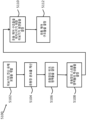
또 다른 실시 예에서, 본 개시는 터보기기를 위한 유동 제어 구조를 설계하기 위한 방법에 관한 것이고, 상기 터보기기는 입구 및 출구를 구비하는 임펠러, 슈라우드, 허브 및 다운스트림 요소를 구비하고, 상기 허브 및 슈라우드는 임펠러 통로(impeller passageway)를 규정한다. 상기 방법은, 컴퓨터를 사용하여 터보기기의 전산 유체 모델(computational fluids model)을 개발(develop)하는 단계; 전산 유체 모델을 이용하여 임펠러 통로 유동장 분포를 계산하는 단계; 상기 유동장 분포에서, 2차 유동의 농도(concentration)를 구비하는 위크 영역을 식별하는 단계; 및 상기 2차 유동을 실질적으로 유동 쪽 방향으로 다운스트림 요소로 가이드 하기 위해 상기 위크 영역에 인접한 상기 허브 및 상기 슈라우드 중 적어도 하나에서 유동 쪽 방향으로 연장하기 위한 적어도 하나의 채널을 설계하는 단계를 포함한다.In another embodiment, the present disclosure relates to a method for designing a flow control structure for a turbomachine, the turbomachine having an impeller with an inlet and an outlet, a shroud, a hub and a downstream element, the hub and the shroud defines an impeller passageway. The method may include developing a computational fluids model of a turbomachine using a computer; Calculating an impeller passage flow field distribution using a computational fluid model; identifying, in the flow field distribution, a wick region having a concentration of secondary flow; and designing at least one channel for extending in a direction toward the flow in at least one of the hub and the shroud adjacent to the wick area for guiding the secondary flow to a downstream element substantially in a direction toward the flow. do.
또 다른 실시 예에서, 본 개시는 2상 유동을 위한 터보기기를 위한 유동 제어 구조를 설계하는 방법에 관한 것이고, 상기 터보기기는 복수 개의 블레이드들을 구비하는 임펠러를 포함하고, 복수 개의 블레이드들 각각은 리딩 엣지 및 트레일링 엣지를 구비하고, 복수 개의 블레이드들 각각은 상기 블레이드의 허브로부터 슈라우드까지 날개 쪽 방향으로 연장하고, 상기 임펠러는 상기 블레이드들의 상기 허브로부터 상기 슈라우드까지 날개 쪽 방향으로 연장하는 메인 임펠러 통로를 규정한다. 상기 방법은, 컴퓨터를 사용하여 터보기기의 전산 모델을 개발하는 단계; 상기 모델을 이용하여 상기 임펠러에 의해서 운반(convey)되는 액체 및 기체의 양을 계산하는 단계; 적어도 하나의 채널을 설계하는 단계; 액체 및 기체 중 하나를 포획(capture) 및 운반하여 메인 임펠러 통로로부터 액체 또는 기체를 제거하기 위한 유동 쪽 방향의 적어도 하나의 유동 쪽 채널을 설계하는 단계를 포함한다.In another embodiment, the present disclosure relates to a method of designing a flow control structure for a turbomachine for two-phase flow, wherein the turbomachine includes an impeller having a plurality of blades, each of the plurality of blades A main impeller having a leading edge and a trailing edge, each of a plurality of blades extending in a wing direction from a hub of the blade to a shroud, and the impeller extending in an wing direction from the hub of the blades to the shroud. define the aisle. The method may include developing a computational model of a turbo machine using a computer; Calculating the amount of liquid and gas conveyed by the impeller using the model; designing at least one channel; and designing at least one flow-side channel in a flow-side direction for capturing and conveying one of the liquid and gas to remove the liquid or gas from the main impeller passage.
또 다른 실시 예에서, 본 개시는 방사상의 터보기기에 관한 것이다. 방사상의 터보기기는 허브 및 복수 개의 블레이드들을 포함하고 입구, 출구 및 회전축을 구비하는 임펠러를 포함하고, 상기 복수 개의 블레이드들 각각은 임펠러 입구에 근접한 리딩 엣지 및 출구에 근접한 트레일링 엣지룰 구비하고, 상기 허브로부터 상기 블레이드의 슈라우드 사이드까지 날개 쪽 방향으로 연장한다. 상기 임펠러는, 상기 작동 유체 내에 유동장을 생성하고, 상기 출구에서의 상기 유동장은 상기 블레이드들의 상기 슈라우드 사이드 및 상기 허브 중 하나에 근접한 위크 사이드와, 상기 블레이드들의 상기 슈라우드 사이드 및 상기 허브 중 다른 하나에 근접한 스트롱 사이드를 포함하고, 상기 유동장의 절대 속도의 자오선 성분은 상기 위크 사이드보다 상기 스트롱 사이드에서 더 크도록 설계 및 구성되고; 슈라우드는 상기 복수 개의 블레이드들에 마주하는 면을 구비하고, 상기 슈라우드 및 상기 허브는 임펠러 통로를 규정하고; 디퓨저는 입구, 슈라우드 사이드 및 허브 사이드를 구비하고, 상기 디퓨저의 상기 슈라우드 사이드 및 상기 허브 사이드는 폭을 구비하는 디퓨저 통로를 포함하고, 상기 디퓨저는 적어도 하나의 스트롱 사이드 핀치 영역을 포함하고, 상기 스트롱 사이드 핀치 영역은 상기 유동장의 상기 스트롱 사이드에 인접한 상기 디퓨저의 상기 슈라우드 사이드 및 상기 허브 사이드 중 하나의 볼록한(convex) 표면을 포함하는 상기 디퓨저 통로 폭의 감소를 제공하고, 상기 볼록한 표면은 상기 디퓨저의 상기 슈라우드 사이드 및 상기 허브 사이드 중 다른 하나의 통로 폭의 감소(reduction)보다 더 많은 감소를 가진 통로를 제공한다.In another embodiment, the present disclosure relates to a radial turbomachine. The radial turbomachine includes an impeller including a hub and a plurality of blades and having an inlet, an outlet, and a rotation shaft, each of the plurality of blades having a leading edge close to the impeller inlet and a trailing edge close to the outlet, It extends in the wingwise direction from the hub to the shroud side of the blade. The impeller creates a flow field in the working fluid, and the flow field at the outlet is at a weak side proximate one of the hub and the shroud side of the blades, and the other one of the hub and the shroud side of the blades. having a proximate strong side, the meridian component of the absolute velocity of the flow field being designed and constructed such that it is greater on the strong side than on the weak side; a shroud has a surface facing the plurality of blades, the shroud and the hub defining an impeller passage; The diffuser has an inlet, a shroud side and a hub side, the shroud side and the hub side of the diffuser including a diffuser passageway having a width, the diffuser including at least one strong side pinch area, the strong The side pinch region provides a reduction in the diffuser passage width including a convex surface of one of the shroud side and the hub side of the diffuser adjacent to the strong side of the flow field, the convex surface of the diffuser Provide a passage having a greater reduction in passage width than the reduction of the passage width of the other of the shroud side and the hub side.
본 발명을 설명하기 위한 목적으로, 도면들은 본 발명의 하나 이상의 실시 예들의 양태들을 도시한다. 그러나, 본 발명은 도면들에 도시된 정확한 배열들 및 수단들에 한정되지 않음을 밝혀둔다.
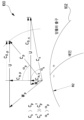
도 1은 임펠러 출구에서의 임펠러 유동장의 유동 분포에 대한 속도 삼각형(velocity triangle)들의 다이어그램이며, 1차(primary) 및 2차(secondary) 유동으로 분해(resolve)되고 절대 및 상대 기준 프레임으로 도시된다.
도 2는 임펠러 출구에서의 자오선 속도(meridional velocity) Cm의 날개 쪽(spanwise) 분포의 개념도이다.
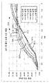
도 3은 높은 유동 조건에서 예시적인 원심 압축기에 대한 다양한 날개 쪽 위치들에 대한 자오선 위치 대 절대 유동 각도의 그래프이다.
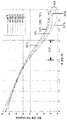
도 4는 예시적인 축 방향 터빈에 대한 다양한 날개 쪽 위치에 대한 자오선 위치 대 절대 유동 각도의 그래프이다.
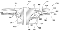
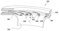
도 5는 유동 가이드 채널들을 구비하는 예시적인 원심 압축기의 부분의 단면도이다.
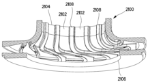
도 6은 도 5에 도시된 원심 압축기의 슈라우드 및 디퓨저의 등가(isometric) 단면도이다.
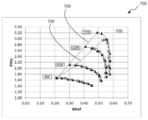
도 7은 본 개시에 따라 제조된 유동 가이드 채널들을 구비한 원심 압축기 및 구비하지 않은 원심 압축기에 대한 시험 데이터를 나타내는 압축기 성능 맵(performance map)이다.
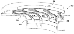
도 8은 유동 가이드 채널들을 구비하는 슈라우드 및 디퓨저의 다른 예시적인 실시 예의 단면 사시도이다.
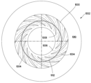
도 9는 유동 가이드 채널들을 갖는 터보기기의 다른 실시 예의 평면도이다.
도 10은 유동 가이드 채널들을 갖는 터보기기의 또 다른 실시 예의 평면도이다.
도 11은 도 10의 터보기기의 부분의 확대도이고, 채널 폭의 변화를 도시한다.
도 12는 유동 가이드 채널들을 갖는 터보기기의 또 다른 실시 예의 평면도이다.
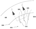
도 13은 도 12의 A-A를 따라 절단한 단면도이고, 유동 가이드 채널들의 예시적인 단면 형상을 도시한다.
도 14는 도 12의 A-A를 따라 절단한 다른 단면도이고, 유동 가이드 채널들의 예시적인 단면 형상을 도시한다.
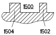
도 15는 도 12의 A-A를 따라 절단한 다른 단면도이고, 유동 가이드 채널들의 예시적인 단면 형상을 도시한다.
도 16은 도 12의 A-A를 따라 절단한 다른 단면도이고, 유동 가이드 채널들의 예시적인 단면 형상을 도시한다.
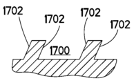
도 17은 도 12의 A-A를 따라 절단한 다른 단면도이고, 유동 가이드 채널들의 예시적인 단면 형상을 도시한다.
도 18은 도 12의 A-A를 따라 절단한 다른 단면도이고, 유동 가이드 채널들의 예시적인 단면 형상을 도시한다.
도 19는 도 12의 A-A를 따라 절단한 다른 단면도이고, 유동 가이드 채널들의 예시적인 단면 형상을 도시한다.
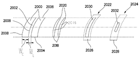
도 20은 예시적인 채널 구조들의 평면도들이다.
도 21은 2상 및/또는 다상(multi-constituent) 유동으로 작동하도록 설계된 터보기기를 위한 유동 가이드 채널들을 구비한 슈라우드 및 디퓨저 의 다른 예시적인 실시 예의 단면도이다.
도 22는 도 21의 슈라우드 및 디퓨저의 다른 단면 사시도이다.
도 23은 2개의 다른 이상적인 프로파일들에 대한 임펠러 출구에서의 날개 쪽 자오선 속도 분포의 다이어그램이다.
도 24는 2개의 일반적인 프로파일 및 이상적인 프로파일에 대한 임펠러 출구에서의 날개 쪽 자오선 속도 분포의 다이어그램이다.
도 25는 유동 가이드 채널들에 의해 증가된 속도 프로파일에 대한 임펠러 출구에서의 날개 쪽 자오선 속도 분포의 다이어그램이다.
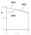
도 26은 일반적인 프로파일 및 증가된 프로파일에 대한 임펠러 출구에서의 날개 쪽 유동 각도 분포의 다이어그램이다.
도 27은 유동 가이드 채널들을 구비하는 터보기기의 다른 실시 예의 평면도이다.
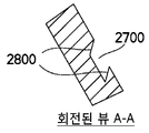
도 28은 도 27의 채널들 중 하나의 단면도이다.
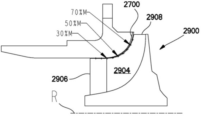
도 29a는 도 29 및 도 28의 터보기기의 일부의 평면도이다.
도 29b는 도 27 내지 도 29a의 터보기기의 측 단면도이다.
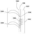
도 30은 유동 가이드 채널들을 갖는 슈라우드의 다른 실시 예의 사시도이다.
도 31은 도 30의 슈라우드와 결합하도록 구성된 베인 디퓨저의 사시도이다. 30.
도 32는 도 30의 슈라우드 및 도 31의 디퓨저가 조립된 사시도이고, 디퓨저 베인들에 대해 상대적으로 클락 포지션(clocked position)에 유동 가이드 채널들을 도시한다.
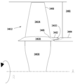
도 33a는 유동 가이드 채널들을 갖는 예시적인 축 방향 기기의 측면도이다.
도 33b는 도 33a의 터보기기의 일부의 평면도이다.
도 34는 유동 가이드 채널들을 갖는 다른 예시적인 축 방향 기기의 측면도이다.
도 35는 도 34의 기기의 부분을 확대하여 도시한 확대 평면도이다.
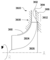
도 36은 강한 사이드 곡률을 구비하는 예시적인 디퓨저의 측 단면도이다.
도 37은 강한 사이드 곡률을 구비하는 다른 예시적인 디퓨저의 측 단면도이다.
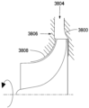
도 38은 강한 사이드 곡률 및 위크 사이드 처리를 구비하는 예시적인 디퓨저의 측 단면도이다.
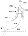
도 39는 강한 사이드 곡률 및 약한 사이드 처리를 구비하는 다른 예시적인 디퓨저의 측 단면도이다.
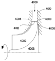
도 40은 강한 사이드 곡률을 구비하는 다른 예시적인 디퓨저의 측 단면도이다.
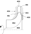
도 41은 강한 사이드 곡률을 구비하는 다른 예시적인 디퓨저의 측 단면도이다.
도 42는 강한 사이드 곡률을 구비하는 다른 예시적인 디퓨저의 측 단면도이다.
도 43은 이중의 강한 사이드 곡률을 구비하는 예시적인 디퓨저의 측 단면도이다.
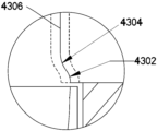
도 44는 도 43의 일부의 확대도이다.
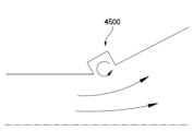
도 45는 예시적인 트랩된 코너 스털 셀(stall cell)의 측면도이다.
도 46은 다른 예시적인 트랩된 코너 스털 셀의 측면도이다.
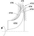
도 47은 강한 사이드 곡률을 구비하는 다른 예시적인 디퓨저의 측 단면도이고, 가능한 슈라우드-사이드 윤곽(contour)들 및 유동 가이드 채널들 중 하나를 도시한다.
도 48은 도 47의 디퓨저의 측 단면도이고, 가능한 슈라우드-사이드 윤곽들 및 유동 가이드 채널들 중 하나를 도시한다.
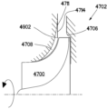
도 49는 도 47의 디퓨저의 측 단면도이고, 가능한 슈라우드-사이드 윤곽들 및 유동 가이드 채널들 중 다른 하나를 도시한다.
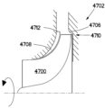
도 50은 도 47의 디퓨저의 측 단면도이고, 가능한 슈라우드-사이드 윤곽들 및 유동 가이드 채널들 중 다른 하나를 도시한다.
도 51은 터보기기를 위한 유동 제어 구조를 설계하기 위한 예시적인 프로세스를 나타내는 흐름도이다.
도 52는 본 개시의 예시적인 실시 예들에 따른 특수한 목적의 컴퓨팅 시스템을 나타내는 블록도이다.For purposes of explaining the present invention, the drawings depict aspects of one or more embodiments of the present invention. However, it should be noted that the present invention is not limited to the precise arrangements and instrumentalities shown in the drawings.
1 is a diagram of velocity triangles for the flow distribution of the impeller flow field at the impeller outlet, resolved into primary and secondary flows and shown in absolute and relative frames of reference. .
2 is a conceptual diagram of the spanwise distribution of the meridional velocity Cm at the impeller outlet.
3 is a graph of meridian position versus absolute flow angle for various blade-side positions for an exemplary centrifugal compressor at high flow conditions.
4 is a graph of meridian position versus absolute flow angle for various blade-side positions for an exemplary axial turbine.
5 is a cross-sectional view of a portion of an exemplary centrifugal compressor having flow guide channels.
6 is an isometric cross-sectional view of the shroud and diffuser of the centrifugal compressor shown in FIG. 5;
7 is a compressor performance map showing test data for a centrifugal compressor with and without flow guide channels manufactured according to the present disclosure.
8 is a cross-sectional perspective view of another exemplary embodiment of a shroud and diffuser with flow guide channels;
9 is a plan view of another embodiment of a turbomachine with flow guide channels.
10 is a plan view of another embodiment of a turbomachine with flow guide channels.
FIG. 11 is an enlarged view of a portion of the turbo machine of FIG. 10 and shows a change in channel width.
12 is a plan view of another embodiment of a turbomachine with flow guide channels.
FIG. 13 is a cross-sectional view taken along line AA of FIG. 12 and shows exemplary cross-sectional shapes of flow guide channels.
FIG. 14 is another cross-sectional view taken along line AA of FIG. 12 and shows exemplary cross-sectional shapes of flow guide channels.
FIG. 15 is another cross-sectional view taken along line AA of FIG. 12 and shows exemplary cross-sectional shapes of the flow guide channels.
Fig. 16 is another cross-sectional view taken along line AA of Fig. 12, showing exemplary cross-sectional shapes of flow guide channels;
FIG. 17 is another cross-sectional view taken along line AA of FIG. 12 and shows exemplary cross-sectional shapes of the flow guide channels.
FIG. 18 is another cross-sectional view taken along line AA of FIG. 12 and shows exemplary cross-sectional shapes of the flow guide channels.
Fig. 19 is another cross-sectional view taken along line AA of Fig. 12, showing exemplary cross-sectional shapes of the flow guide channels.
20 are top views of exemplary channel structures.
21 is a cross-sectional view of another exemplary embodiment of a shroud and diffuser with flow guide channels for a turbomachine designed to operate with two-phase and/or multi-constituent flow.
22 is another sectional perspective view of the shroud and diffuser of FIG. 21;
Figure 23 is a diagram of the blade side meridional velocity distribution at the impeller exit for two different ideal profiles.
24 is a diagram of the blade side meridional velocity distribution at the impeller exit for two typical and ideal profiles.
Figure 25 is a diagram of the blade side meridional velocity distribution at the impeller outlet for the velocity profile augmented by the flow guide channels.
26 is a diagram of the wing-side flow angle distribution at the impeller outlet for normal and augmented profiles.
27 is a plan view of another embodiment of a turbomachine having flow guide channels.
28 is a cross-sectional view of one of the channels of FIG. 27;
29A is a plan view of a portion of the turbomachine of FIGS. 29 and 28;
29B is a side cross-sectional view of the turbo machine of FIGS. 27 to 29A.
30 is a perspective view of another embodiment of a shroud with flow guide channels;
31 is a perspective view of a vane diffuser configured to mate with the shroud of FIG. 30; 30.
32 is an assembled perspective view of the shroud of FIG. 30 and the diffuser of FIG. 31 , showing the flow guide channels in a clocked position relative to the diffuser vanes.
33A is a side view of an exemplary axial instrument with flow guide channels.
33B is a plan view of a portion of the turbomachine of FIG. 33A.
34 is a side view of another exemplary axial instrument with flow guide channels.
FIG. 35 is an enlarged plan view illustrating an enlarged portion of the device of FIG. 34 .
36 is a cross-sectional side view of an exemplary diffuser with strong side curvature.
37 is a cross-sectional side view of another exemplary diffuser with strong side curvature.
38 is a cross-sectional side view of an exemplary diffuser with strong side curvature and weak side treatment.
39 is a cross-sectional side view of another exemplary diffuser with strong side curvature and weak side treatment.
40 is a cross-sectional side view of another exemplary diffuser having a strong side curvature.
41 is a cross-sectional side view of another exemplary diffuser having a strong side curvature.
42 is a cross-sectional side view of another exemplary diffuser having a strong side curvature.
43 is a cross-sectional side view of an exemplary diffuser with double strong side curvature.
Fig. 44 is an enlarged view of a portion of Fig. 43;
45 is a side view of an exemplary trapped corner stall cell.
46 is a side view of another exemplary trapped corner stall cell.
47 is a cross-sectional side view of another exemplary diffuser with strong side curvature, showing one of possible shroud-side contours and flow guide channels.
48 is a cross-sectional side view of the diffuser of FIG. 47, showing one of the possible shroud-side contours and flow guide channels.
49 is a cross-sectional side view of the diffuser of FIG. 47, showing another of possible shroud-side contours and flow guide channels.
50 is a cross-sectional side view of the diffuser of FIG. 47, showing another of possible shroud-side contours and flow guide channels.
51 is a flow diagram illustrating an exemplary process for designing a flow control structure for a turbomachine.
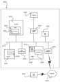
52 is a block diagram illustrating a special purpose computing system according to example embodiments of the present disclosure.
본 개시의 양태들은, 터보기기의 성능에 대한 부정적인 손실들의 영향을 감소시키고, 터보기기의 성능을 향상시키고, 업스트림(upstream) 요소에서 생성된 다운스트림(downstream) 요소의 부정적인 손실들의 영향을 감소시키고, 업스트림 및 다운스트림 요소의 커플링(coupling) 및 성능을 향상시키는 것들 중 하나 이상을 수행하기 위하여 설계 및 구성되는 구조들 및 유동 제어 장치들을 포함한다. 아래에서 보다 상세히 설명되는 바와 같이, 본 개시에 따라 제조된 예시적인 유동 제어 장치들은 다양한 유동 가이드 채널들, 리브(rib)들, 디퓨저 통로-폭 감소(diffuser passage-width reduction)들 및 다른 처리(treatment)들을 포함할 수 있고, 이는 기기의 슈라우드 및 허브 사이드 중 하나 또는 둘 모두에 위치될 수 있고, 터보기기 유동장의 일부들을 방향 전환(redirect), 가이드 또는 다른 영향을 미치고 기기의 성능을 향상시킨다.Aspects of the present disclosure reduce the impact of negative losses on the performance of the turbomachine, improve the performance of the turbomachine, reduce the impact of negative losses in the downstream element generated in the upstream element, and structures and flow control devices designed and constructed to perform one or more of: improving performance and coupling of upstream and downstream components. As described in more detail below, exemplary flow control devices made in accordance with the present disclosure incorporate various flow guide channels, ribs, diffuser passage-width reductions, and other treatments ( treatments, which may be located on one or both of the shroud and hub sides of the machine, redirect, guide or otherwise affect parts of the turbomachine flow field and improve the performance of the machine. .
방사상(radial), 축 방향(axial) 또는 혼합 유동(mixed flow) 및 압축기들, 펌프들 또는 터빈들의 터보기기는 일반적으로 복수 개의 블레이드들을 포함하고 회전축을 중심으로 회전하고 유체 통로 내에 배치된 임펠러(impeller)를 포함한다. 본원에서 사용되는 용어 "임펠러"는 압축기들, 터빈들, 펌프들 및 팬(fan)들을 포함하고 모든 유형의 터보기기의 블레이드 형 임펠러 또는 로터(rotor)를 지칭한다. 터보기기 임펠러들은 입구(inlet) 및 출구(exit)를 가지며 일반적으로 디퓨저 또는 캐스케이드(cascade) 또는 노즐 또는 스테이터(stator)와 같은 다운스트림 요소와 유체 소통한다. 표면 마찰, 틈새 간격 유동(clearance gap flow)들, 누설 및 회전 기기의 기본적인 특성으로 인한 와류(vorticity)들로 인한 손실들과 같은 실제 효과들로 인해 임펠러 유동장에 불균일(non-uniformities)들이 발생한다. 이러한 불균일들은 임펠러 통로 내의 유체 속도의 크기 및 각도의 불균일들의 관점에서 설명될 수 있고, 유동장의 저손실 영역들은 일반적으로 임펠러 통로를 따르는 것과 같이 제 1 방향으로 실질적으로 정렬되고, 유동장의 다른 영역들은 다양한 다른 각도들 및 속도들 운반(convey)되고, 다른 각도들 및 속도들은 메인 임펠러 통로 방향에 대해 수직한 방향 및 반대 방향을 포함한다. 이러한 오프-각도 유동장 불균일들은 시스템의 손실들을 나타내고, 유동 불안정들, 다운스트림 요소의 스톨(stall), 임펠러의 역류(back flow) 또는 대형 임펠러 출구 공기역학적 막힘(blockage)과 같은 추가 손실들을 유발할 수 있다. 본원 및 첨부된 청구범위들에서 사용되는 용어 "1차 유동" 및 유사한 용어들은 통로 방향과 실질적으로 정렬되는 임펠러 유동장의 저손실 또는 제로손실 부분을 지칭하고, "2차 유동" 및 이와 유사한 용어들은 작동 유체 유동장의 다른 부분들을 지칭하고 와류 및 상당한 손실들을 포함 할 수 있다.Turbomachinery of radial, axial or mixed flow and compressors, pumps or turbines generally comprises a plurality of blades and an impeller ( impeller). As used herein, the term "impeller" refers to a bladed impeller or rotor of all types of turbomachinery including compressors, turbines, pumps and fans. Turbomachinery impellers have an inlet and an exit and are generally in fluid communication with a downstream element such as a diffuser or cascade or nozzle or stator. Non-uniformities in the impeller flow field occur due to practical effects such as surface friction, clearance gap flows, leakage and losses due to vorticities due to the fundamental properties of rotating machinery. . These non-uniformities can be described in terms of non-uniformities in the magnitude and angle of the fluid velocity within the impeller passage, wherein the low-loss regions of the flow field are generally substantially aligned in the first direction, such as along the impeller passage, and other regions of the flow field are variously Different angles and velocities are conveyed, and different angles and velocities include directions perpendicular to and opposite to the main impeller passage direction. These off-angle flow field inhomogeneities represent losses in the system and can cause additional losses such as flow instability, stall of a downstream element, back flow of the impeller or aerodynamic blockage at the outlet of a large impeller. there is. As used herein and in the appended claims, the term "primary flow" and like terms refers to the low-loss or zero-loss portion of the impeller's flow field that is substantially aligned with the passage direction, and "secondary flow" and like terms refer to the operating Refers to different parts of the fluid flow field and can include eddies and significant losses.
도 1은 임펠러 출구(102)에서의 작동 유체 속도 분포(100)에 대한 개략적인 다이어그램이며, 1차 유동(p) 및 2차 유동(s)으로 분해되고 절대 및 상대 기준 프레임(frame of reference)로 도시된다. 특히, 속도들(C)은 절대 또는 고정된 기준 프레임(예를 들어, 지구)에 있고 속도들(W)은 상대 운동 프레임(임펠러로 회전하는 관찰자)에 있다. U는 임펠러 주변부(peripheral) 또는 팁 휠 속도이다. 도 1은 2개의 세트들의 속도들을 도시한다: 첨자 "p"를 갖는 더 큰 삼각형은 1차 유동장에 대한 벡터 속도들을 나타낸다. 첨자 "s"가있는 더 평평한 삼각형은 2차 유동의 벡터 속도들을 나타낸다. Cm, p 및 Cm, s는 절대 프레임에서 1차 및 2차 속도의 자오선 성분들이고 순수한 방사상의 스테이지들의 방사상의 속도이다. αp 및 αs는 임펠러 중심선 회전축을 통과하는 자오선 기준 평면을 기준으로 한 절대 기준 프레임에서 측정된 절대 유동 각도들이다. 도 1은 유동장의 1차 및 2차 성분들의 간략화된 표현이고, 2차 유동 속도 삼각형들은 단일 크기 및 각도(절대 또는 상대 프레임 중 어느 하나)로 다양한 각도들 및 속도들을 갖는 매우 복잡한 유동 분포의 평균값을 나타낸다. Figure 1 is a schematic diagram of the working
한편, 도 1은 임펠러 출구에서의 전형적인 유동 변화들의 간략화된 표현이고, 상대적 큰 속도 WP 및 자오선 속도 Cm, p를 구비하는 유동장의 1차 성분이 상대적 프레임 내에서 잘 통전(energize)되고, 한편, 현저하게 낮은 상대적 속도 Ws 및 자오선 속도 Cm, s를 구비하는 2차 유동은 회전 시스템에서 잘 통전되지 않는다. 또한, 임펠러 출구 유동장은 일반적으로 상이한 유동 각도들의 어레이를 구비하고, 도 1에서 αp 및 αs로 단순화되고, 2차 유동은 1차 유동에 비해 일반적으로 큰 평균 절대 각도 αs를 구비한다는 것을 나타낸다. 유동 각도들에서의 이러한 분포는 높은-각도 및 저 자오선 운동의 2차 유동 스트림튜브들이 임펠러의 출구 부분에서 1차 유동 튜브와 결합하여 혼합되기 때문에 유동이 임펠러 출구(102)를 통과함에 따라 혼합 손실들을 야기한다. On the one hand, Figure 1 is a simplified representation of typical flow changes at the impeller outlet, the first order component of the flow field with a relatively large velocity WP and a meridional velocity Cm, p is well energized within the relative frame, on the other hand, Secondary flows with significantly lower relative velocities Ws and meridional velocities Cm,s do not conduct well in rotating systems. Also, the impeller exit flow field usually has an array of different flow angles, simplified to αp and αs in Figure 1, indicating that the secondary flow generally has a larger mean absolute angle αs than the primary flow. This distribution at flow angles results in mixing losses as the flow passes through the
또한, 이와 같이 큰 Cm, s를 갖는 큰 각도의 2차 유동은 자오선 방향에서 낮은 운동으로 인한 유동 불안정, 스톨 및 유동 역전(reversal)을 야기한다. 큰 2차 유동 각도들은 후속하는 베인 요소, 예를 들어 베인 디퓨저, 스테이터 또는 다른 캐스케이드 또는 후속하는 베인리스(vaneless) 요소, 예를 들어, 베인리스 디퓨저에서의 높은 손실들과 관련된 길고 얕은 나선형 유동 경로에서의 리딩 엣지(leading edge)에서의 스톨로 이어질 수 있다. 이러한 2차 유동은 임펠러 및 다운스트림 요소 사이의 열악한 커플링 및 열악한 상호작용을 야기할 수 있고, 이는 임펠러 및 다운스트림 요소 모두에 대한 성능 저하를 초래할 수 있다.In addition, such a large-angle secondary flow with large Cm,s causes flow instability, stall, and flow reversal due to low motion in the meridional direction. Large secondary flow angles are associated with high losses in a subsequent vane element, eg a vane diffuser, stator or other cascade, or a subsequent vaneless element, eg a vaneless diffuser, associated with a long, shallow helical flow path. may lead to a stall at the leading edge of This secondary flow can cause poor coupling and poor interaction between the impeller and the downstream element, which can result in performance degradation for both the impeller and the downstream element.
도 2 내지 도 4는 공간적으로 2차 유동들이 어떻게 시작될 수 있는 가를 보여주고, 기기의 특정 위치들에 집중될 수 있다. 도 2는 임펠러 출구에서의 이상적인(202) 및 일반적인(204) 날개 쪽의 속도 분포를 나타내고, Cm 또는 임펠러 유동 절대 속도의 자오선 성분을 수직축에 나타내고, % b2 또는 날개 쪽 위치를 수평축에 나타낸다. 나타난 예에서 0은 슈라우드 표면을 나타내고 1.0은 허브 표면을 나타낸다. 도시된 바와 같이, 이상적인 임펠러 출구 유동 속도 분포(202)는 얇은 경계층(boundary layer)들을 갖는 클린(clean)하고 대칭인 프로파일을 포함할 수 있지만, 실제 일반적인 분포(204)는 임펠러 통로의 슈라우드 사이드를 따라, 특히 후반 또는 적어도 임펠러 통로의 출구 부분(자오선 방향)에 낮은 Cm이 집중되는 2차 유동을 포함할 수 있다. 기기의 슈라우드 표면을 따라 저-통전(low-energized) 유동이 발생하는 것이 일반적이지만 일부 기기들 및 작동 조건들의 경우 상황이 바뀌고 허브 표면을 따라 더 낮은 Cm 2차 유동이 집중될 수 있다.Figures 2-4 show how spatially secondary flows can be initiated and concentrated at specific locations in the device. Figure 2 shows the ideal (202) and normal (204) blade-side velocity distributions at the impeller outlet, with Cm or the meridional component of the impeller flow absolute velocity on the vertical axis and % b2 or blade-side position on the horizontal axis. In the example shown, 0 represents the shroud surface and 1.0 represents the hub surface. As shown, an ideal impeller outlet flow
도 3은 임펠러가 대략 4°의 입사각을 갖는 정상 상태 고 유동 조건에서 예시적인 원심 압축기의 날개 쪽 절대 유동 각도 변화의 전산 유체 역학(CFD, computational fluid dynamics) 계산들의 결과들을 나타내는 예시적인 그래프이다. 도 3에서, 절대 유동 각도 α는 수직 축 상에 도시되고, % M, 즉, 자오선 방향의 임펠러 유동 경로의 백분율은 수평축을 따라 도시되고, 여기서 0은 임펠러 리딩 엣지이고, 1.0은 임펠러 트레일링 엣지이다. 다양한 라인들은 블레이드로부터 블레이드까지의 원주 방향(circumferential direction)으로 평균된 날개 쪽 방향(0%는 허브 표면이고, 100%는 슈라우드 표면임)이 변화하는 지점에서의 스트림튜브(streamtube)들을 시뮬레이션한다. 도 3에 도시된 바와 같이, 날개 쪽 방향(내부 스팬 쪽 부분, 300)의 임펠러 유동장의 처음 60-70%는 실질적으로 유사한 절대 유동 각도들을 가지고 실질적으로 유사한 궤적을 따르는 상당히 긴밀한(tight) 그룹을 갖는다. 스트림튜브들의 내측 날개 쪽 부분(300)의 궤도는 임펠러의 출구 영역에서 평평해지기 쉽고 대략 60도의 공칭 출구 각도에 근사하는 경향이 있다. 내부 날개 쪽 방향 부분(300)은 1차 유동에 대략 근사하고, 60도의 공칭 출구 각도는 대체로 1차 유동 평균 절대 각도, αp다(도 1 및 대응한 설명 참조). 대조적으로, 날개 쪽 방향(외부 날개 쪽 부분, 302)의 외측 약 15-30%는 발산 영역(304)에서 높은-각도 2차 유동에 의해 지배되기 시작하는 것으로 나타나고, 도시된 실시 예에서는 대략 70% 통로의 자오선 위치를 나타내고, 2차 유동장들의 일반적인 높은-각도 유동으로 발산하고, 본원에서 논의된 다양한 손실들을 야기하는 것으로 이해된다. 유사한 CFD 계산들은 발산 영역(304)의 대략 자오선 위치가 작동 조건들의 변화들에 따라 변할 수 있지만, 유동장이 더 낮은 유동 조건들에서 유사한 특성들을 갖는다는 것을 보여준다. 예를 들어, 발산 영역의 자오선 위치는 최대 업스트림 위치 및 최대 다운스트림 위치 사이에서 기기의 작동 범위에 걸쳐(across) 다를 수 있다. 통상의 기술자라면 알 수 있는 바와 같이, 도 3은 단지 예시일 뿐이고, 특정한 백분율들 및 위치들은 예를 들어 임펠러 설계 및 기기 유형에 따라 변할 수 있고, 경우에 따라 높은-각도 2차 유동 영역이 허브 표면 상에 존재할 수 있다. 도 4는 예시적인 축 방향 터빈에서 복수 개의 시물레이션된 날개 쪽 스트림튜브들에 대한 자오선 위치 대 절대 유동 각도를 유사하게 나타낸다. 도시된 바와 같이, 외부 90-95% 날개 쪽 유동(외부 날개 쪽 부분, 400)은 임펠러의 출구 부분에서 발산 영역(402)의 구역에서 2차 유동에 의해 영향을 받기 시작하고, 예를 들어, 발산 영역은 도시된 예에서 대략 50-70%M이고, 1차 유동장으로부터 발산하는 유동 각도에 의해 특징 지어진다. 따라서, 도 2 내지 도 4에 도시된 바와 같이, 오프-각도(off-angle) 2차 유동은 발산 영역에서 발생하기 시작할 수 있고, 허브 또는 슈라우드 표면을 따라 그리고 임펠러 유동장의 출구 부분을 향해 집중될 수 있다. 전술한 바와 같이, 이러한 2차 유동은 터보 기기의 손실들을 나타낸다.FIG. 3 is an exemplary graph showing the results of computational fluid dynamics (CFD) calculations of the absolute flow angle change across the blades of an exemplary centrifugal compressor in a steady state high flow condition where the impeller has an angle of incidence of approximately 4°. In Fig. 3, the absolute flow angle α is plotted on the vertical axis, and % M, i.e., the percentage of the impeller flow path in the meridional direction, is plotted along the horizontal axis, where 0 is the impeller leading edge and 1.0 is the impeller trailing edge. am. The various lines simulate streamtubes at points where the averaged aerosol direction (0% is the hub surface, 100% is the shroud surface) changes in the circumferential direction from blade to blade. As shown in FIG. 3, the first 60-70% of the impeller flow field in the wing-side direction (inner span-side portion, 300) forms a fairly tight group that follows a substantially similar trajectory with substantially similar absolute flow angles. have The trajectory of the inner wing-
이하에서 더 상세히 설명하는 바와 같이, 본 개시는 다양한 유동 제어 구조들을 포함하고, 유동 제어 구조들은 2차 유동들이 터보기기의 성능에 미치는 영향을 최소화하도록 설계 및 구성됨으로써 터보기기의 성능을 향상시키고, 작동 범위, 스테이지 압력 상승(압축기들 및 펌프들에 대한) 및/또는 스테이지 효율들을 향상시키고, 경우에 따라 임펠러 유동장과 다운스트림 요소 유동장의 커플링을 향상시킬 수 있다. 또한 이하에서 더 설명되는 바와 같이, 이러한 유동 제어 구조들은 임펠러 통로 및 다운스트림 요소 통로 모두에 위치될 수 있고, 임펠러 출구를 가로질러 연장되고 임펠러 출구와 오버랩(overlap) 되거나 단지 임펠러 또는 다운스트림 요소 통로에 위치될 수 있다. 유동 제어 구조들은 일반적으로 유동 쪽 방향으로 연장하고 바람직한 각도로 임펠러 유동장의 부분들을 방향 전환하도록 치수화된(dimension) 유동 가이드 채널들을 포함할 수 있다. 이러한 채널들은 다양한 단면 크기들, 형상들 및 다양한 상이한 깊이 윤곽들을 가질 수 있다. 일부 실시 예들에서, 이러한 채널들은 2차 유동의 농도(concentration)를 갖는 표면을 따라 임펠러 통로의 출구 부분에 위치될 수 있고, 채널들은 2차 유동의 부분들을 다운스트림 요소로 가이드 하도록 설계 및 구성되고, 출구 혼합 손실들을 감소시키고, 유동 안정성을 향상시키며, 임펠러 및 다운스트림 측 요소의 커플 링을 향상시킨다. 예시적인 유동 제어 구조들은 또한 더 약한 저 운동의 유동이 존재하는 디퓨저 통로의 반대편 사이드의 유동장에 영향을 주도록 설계 및 구성된 고 운동의 유동을 구비하는 디퓨저 통로의 사이드 상에 위치된 디퓨저 사이드 벽 곡률들을 포함할 수 있고, 디퓨저 성능을 향상시킬 수 있다.As described in more detail below, the present disclosure includes various flow control structures, which are designed and configured to minimize the effect of secondary flows on the performance of the turbo machine, thereby improving the performance of the turbo machine, It can improve the operating range, stage pressure rise (for compressors and pumps) and/or stage efficiencies, and possibly improve the coupling of the impeller flow field with the downstream element flow field. Also as described further below, these flow control structures can be located in both the impeller passage and the downstream element passage, extend across and overlap the impeller outlet, or just the impeller or downstream element passage. can be located in Flow control structures may include flow guide channels that generally extend in a direction toward the flow and are dimensioned to redirect portions of the impeller flow field at a desired angle. These channels can have a variety of cross-sectional sizes, shapes and a variety of different depth contours. In some embodiments, these channels can be located at the exit portion of the impeller passage along a surface with a concentration of secondary flow, the channels being designed and configured to guide portions of the secondary flow to a downstream element. , reduce outlet mixing losses, improve flow stability, and improve coupling of impeller and downstream side element. Exemplary flow control structures may also accommodate diffuser sidewall curvatures located on the side of a diffuser passage with high motion flow that is designed and configured to affect the flow field on the opposite side of the diffuser passage where the weaker low motion flow is present. It can be included, and can improve the diffuser performance.
도 5 및 도 6은 임펠러 슈라우드(504) 내에 회전 가능하게 배치되고 베인리스 디퓨저(506)의 업스트림에 위치되는 임펠러(502)를 구비하는 예시적인 원심 압축기(500)를 도시한다. 임펠러(502)는 입구(512) 및 출구(514)뿐만 아니라 복수 개의 블레이드(508, 일부는 라벨링 됨)들을 포함한다. 임펠러 블레이드(508)들은 리딩 엣지(도시되지 않음) 및 트레일링 엣지(516) 사이에서 자오선 방향으로 연장하고 임펠러 블레이드(508)의 허브(518) 및 슈라우드 사이드(520) 사이에서 날개 쪽 방향으로 연장한다. 슈라우드(504, 때로는 케이싱(casing)으로도 지칭 됨)는 임펠러 입구(512)로부터 출구(514)까지 연장하고, 임펠러 블레이드(508)들의 슈라우드 사이드(520)들을 마주하는 면(522)을 포함한다. 임펠러 허브(518) 및 슈라우드(504)는 작동 유체가 압축되어 출구(514)에서 디퓨저(506)로 배출될 수 있는 임펠러 통로(523)를 규정한다. 디퓨저(506)는 앞면(526, front surface)을 규정하는 앞판(524, front plate) 및 뒷면(530, back surface)을 규정하는 후 뒷판(528, back plate)를 포함한다. 디퓨저 입구(532) 및 임펠러 출구(514)는 유사한 크기로 실질적으로 정렬될 수 있고, 슈라우드(504) 및 디퓨저 앞면(526)은 실질적으로 임펠러 출구(514)에 정렬될 수 있고, 디퓨저 입구(532), 허브(518) 및 디퓨저 뒷면(530)은 유사하게 실질적으로 임펠러 출구/디퓨저 입구에 정렬될 수 있다. 도시된 예에서, 블레이드(508)의 슈라우드 사이드(520)들 사이에 작은 간극이 있고, 임펠러가 고정 슈라우드(504)에 대해 회전하도록 구성되는 임펠러(502)가 개구(open)되어 있다. 마찬가지로, 허브 디스크 외측 반경(534) 및 디퓨저 뒷판(528) 사이에는 작은 간극이 있고, 슈라우드(504) 및 디퓨저 앞판(524)은 이러한 갭(gap)을 포함하지 않을 수도 있고, 임펠러(502) 및 디퓨저(506) 사이에 하나의 연속적인 표면을 형성할 수도 있다.5 and 6 show an exemplary
도 5 및 도 6에 도시된 바와 같이, 슈라우드(504)는 슈라우드 둘레에 원주 방향으로 배치되고, 임펠러 통로(523), 임펠러 출구(514)의 업스트림 내의 시작 위치(604)에서 유동 쪽 방향으로 일반적으로 연장하는 복수 개의 유동 가이드 채널(602, 혼란을 피하기 위해 일부만 라벨링 함)들을 포함할 수 있고, 도시된 실시 예에서, 앞판(526)의 앞면(524)을 따라 디퓨저(506)로 연장할 수 있다. 예시적인 채널(602)들은 임펠러(502)의 출구 영역에서 슈라우드(504)를 따라 발생하는 2차 유동의 부분을 가이드 하도록 설계 및 구성된다. 예를 들어, 도 3에서 도시되는 것과 같은 날개 쪽 절대 유동 각도 계산들은, 채널(602)들의 시작 위치(604)들을 결정하는데 사용될 수 있다. 일 실시 예에서, 시작 위치(604)들은 계산된 발산 영역, 예를 들어, 발산 영역(304, 도 3 참조)에 근접할 수 있고, 여기에서 높은 절대 각도 2차 유동이 발생되기 시작한다. 비-한정적인 예로, 시작 위치(604)들은 도 3에서 도시된 실시 예에 대해 약 70%의 자오선 위치에 위치될 수 있고, 채널(602)들은 적어도 임펠러 출구(514)까지 연장할 수 있고, 도시된 실시 예에서 디퓨저(506) 내로 다운스트림으로 연장하여 임펠러(502)로부터 디퓨저(506)로 유동의 자오선 성분을 증가시키는 바람직한 방향으로 2차 유동을 유도할 수 있고, 출구 혼합 손실들을 감소시키고, 디퓨저(506)의 입구 영역에서의 유동 안정성을 향상시킨다.5 and 6, the
일 실시 예에서, 채널(602)들의 곡률 또는 각도는 1차 유동 절대 유동 각도 αp(도 1 참조)와 실질적으로 동일할 수 있고, 채널들의 각도는 채널들의 전체 길이를 따라 실질적으로 일정할 수 있다. 이러한 1차 유동 각도는 실제 기기의 레이저 속도계 측정들 및/또는 CFD 계산들을 포함하는 다양한 방법으로 결정될 수 있다. 비 제한적 예로, 도 3에 도시된 방사상의 압축기를 위해 설계 및 구성된 채널(602)들은, 임펠러(502)의 출구 영역에서 1차 유동이 근사하는 평균 각도와 실질적으로 동일한 각도인, 대략 60 °의 일정한 절대 각도 α를 가질 수 있다. 이하 서술하는 바와 같이, 다른 실시 예들에서, 채널(602)들은 변하는 각도를 가질 수 있다. 일 실시 예에서, 채널(602)들의 각도는 1차 유동의 궤적을 근사할 수 있고, 따라서, 예컨대 발산 영역(304)의 업스트림인 임펠러(502)의 제 1 부분에 대한 제 1 각도 또는 제 1 시리즈 각도들을 가질 수 있고, 채널(602)들의 각도는 발산 영역의 다운스트림 위치들에 대한 제 2 각도 또는 제 2 각도들을 가질 수 있고, 일부 예들에서, 채널들의 각도는 임펠러 출구(514)의 다운스트림 위치들 및 디퓨저(506)로 연장하는 채널들에서 계속해서 변할 수 있다. 아래에서보다 상세히 설명하는 바와 같이, 또 다른 예들에서, 채널(602)들은 1차 유동 각도와 실질적으로 동일하지 않은 각도를 가질 수 있다. 예를 들어, 방사상의 기기에서는 2차 유동을 유도하기 위해 각도가 1차 유동 각도보다 작을 수 있고, 경우에 따라 1차 유동 각도를 의도적으로 초과하는 각도로 일부 1차 유동을 유도 할 수 있다.In one embodiment, the curvature or angle of the
따라서, 도시된 채널(602)들은 임펠러(502)의 출구 영역에 위치되고 슈라우드(504)를 따라 배치됨으로써, 2차 유동을 방향 전환시키고 전술한 2차 유동의 부정적 효과들의 실질적인 부분을 치유하는데(cure) 효과적일 수 있다. 예를 들어, 채널(602)들은 상당한 와류를 포함하고, 1차 유동의 방향으로 낮은 자오선 운동을 구비하는 높은-각도 2차 유동을 가이드하고, 유동의 운동의 자오선 성분을 증가시킬 수 있다. 채널(602)들의 방향 전환된 유동은 임펠러 출구의 다운스트림 위치들에서 임펠러 출구(514) 유동장의 나머지와 재결합(re-combine)하여 유동 각도들의 보다 동질의 분포로 인한 출구 혼합 손실들을 감소시키고, 예를 들어, 디퓨저(506)로 들어가는 유동이 안정적일 수 있다.Thus, the illustrated
이하에서 더 상세하게 설명되는 바와 같이, 채널(602)들과 같은 유동 가이드 채널들의 시작 및 종료 위치들 및 각도를 변화시키는 것에 추가하여, 채널들의 다른 모든 파라미터들은 설계 의도 및 용도에 따라 조정 및 맞춰(tailor)질 수 있다. 예를 들어, 도 5 및 도 6에 도시된 바와 같이, 채널(602)들의 폭(WC)은 채널들 사이에서 연장하는 랜드(606, 단지 일부만이 라벨링되어 있음)들의 폭(WL)보다 작다. 예시된 실시 예에서, WC는 WL의 대략 30%이다. 다른 실시 예들에서, 채널들 및 인접한 랜드들의 상대 폭, 슈라우드 또는 허브에 위치된 채널들의 수 및 채널들의 원주방향 간격은 다양할 수 있다. 또한, 도시된 예에서, 채널(602)들은 2차 유동에 의해 지배되는 임펠러 유동장의 날개 쪽 부분을 수용하도록 설계 및 구성된 최대 깊이를 구비한다. 예를 들어, 도시된 채널(602)들은 도 3에 도시된 유동장 성능을 갖는 예시적인 압축기를 위해 설계되고, 임펠러 출구(514)에서 허브 표면(540) 및 슈라우드 면(522) 사이에 날개 쪽 거리의 대략 5%-30% 범위의 최대 깊이를 구비할 수 있다. 다른 실시 예들에서, 채널(602)들의 최대 깊이는, 터보기기 유동 상의 채널들의 원하는 충격 및 채널들의 원하는 기능을 포함하는 다양한 고려 사항(consideration)에 따라 변화될 수 있다. 일부 실시 예들에서, 최대 채널 깊이는 날개 쪽 거리의 5% 이하일 수 있고, 다른 실시 예에서는 날개 쪽 거리의 50%-100% 또는 100% 초과일 수 있다. 자오선 방향의 깊이 윤곽도 변화할 수 있다. 예를 들어, 도시된 채널(602)들은 시작 위치(604)들 및 임펠러 출구(514) 사이에서 연장하는 초기 입구 영역에 걸쳐 점차적으로 증가하는 깊이를 구비한다. 이러한 점차적으로 증가하는 깊이는 슈라우드(504)를 따라 발생하는 2차 유동의 증가 양을 설명할 수 있다. 채널 깊이는 임펠러 플레이트 트레일링 엣지(516)들의 업스트림, 인접 또는 다운스트림을 포함하는 다양한 위치들에서 최대 위치에 도달할 수 있다. 도시된 예에서, 채널(602)들은 트레일링 엣지(516)들에 실질적으로 인접한 위치에서 최대 깊이에 도달한 후, 깊이가 점차적으로 감소할 수 있는 종료 유치(도시되지 않음)에 도달할 때까지 디퓨저(506)에서 실질적으로 일정한 깊이를 구비하고, 메인 디퓨저 통로로 부드럽게 되돌아간다.In addition to varying the start and end positions and angles of flow guide channels, such as
유동 가이드 채널(602)들은 또한 2차 유동에 의해 지배되는 슈라우드 표면을 따라 임펠러 유동장의 원하는 체적 부를 수용하는 크기의 단면적을 갖도록 구성되고 치수화될 수 있다. 도시된 예에서, 채널(602)들은 테이퍼된(taper) 측벽들을 갖는 실질적으로 정사각형인 단면을 구비한다. 아래에서 논의되는 바와 같이, 다양한 다른 횡단면들이 사용될 수 있다. The
도 7은 채널(602)들과 같은 유동 가이드 채널들로 얻어질 수 있는 몇 가지 이점들을 보여주는 예시적인 시험 데이터를 도시한다. 도 7은 수직축을 따라 압력비(PRts) 및 수평축을 따라 기존된 질량 유동(Mref)을 갖는 압축기 성능 맵(700)을 도시한다. 사각형 심볼 라인들은 유동-가이드 채널들이 없는 베인리스 디퓨저로부터의 라인들이고, 삼각형 심볼 라인들은 채널(602)들과 같은 유동 가이드 채널들을 갖는 동일한 기기로부터의 라인들이다. 각각의 채널 및 채널이 없는 경우들에 대한 서지 라인(706, 708)들은, 채널(602)들이 압축기 서지 라인에 상당한 영향을 미침으로써 기기의 작동 범위를 상당히 증가시키는 것을 나타낸다. 또한, 본 발명자에 의한 시험은 채널(602)들과 같은 유동 가이드 채널들의 사용이 압축기 스테이지로부터 더 높은 압력 상승 및 더 큰 일 입력뿐만 아니라 디퓨저 성능을 향상시킬 수 있음을 나타낸다. 특정 이론에 국한되지 않고, 채널들(602)에 기인한 향상된 성능은 메인 임펠러 통로(523)로부터 2차 유동의 일부를 제거하고, 개선된 각도로 높은-와류 유동을 방향 전환함으로써, 임펠러 출구(514)의 다운스트림에서의 혼합 손실들을 감소시키고, 디퓨저 앞면(526)을 따라 유동의 안정성을 향상시킨다.FIG. 7 shows example test data showing some of the benefits that can be obtained with flow guide channels such as
도 8은 베인 디퓨저(802, vaned diffuser)의 업스트림에 위치된 다른 예시적인 임펠러 슈라우드(800)의 일부를 도시한다. 도시된 바와 같이, 슈라우드(800)는 임펠러 유동장의 일부를 가이드 하기 위한 유동 가이드 채널(804, 일부만 라벨링되어 있음)들을 포함할 수 있다. 채널(602)들과 유사하게, 채널(804)들은 임펠러 출구(808)의 업스트림에 있는 시작 위치(806)를 구비할 수 있고, 도시된 실시 예에서, 채널들은 디퓨저 베인(812)의 리딩 엣지(810)의 업스트림, 디퓨저(802)로 연장할 수 있다. 일 실시 예에서, 채널(804)들은 1차 유동 성분의 절대 각도 αp와 대략 동일한 일정한 각도 α를 구비할 수 있다. 일부 실시 예들에서, 채널(804)들의 각도는 채널이 디퓨저(802)의 적절한 각도에서 유동을 효과적으로 가이드 하도록 디퓨저 베인(812)들의 각도와 거의 동일할 수 있다. 일 실시 예에서, 채널(804)들 및 베인(812)들의 각도는 커플링된 시스템으로서 설계 및 구성될 수 있고, 각도들은 특정 임펠러의 유동 특성들에 기초하여 선택될 수 있다. 예를 들어, 일 실시 예에서, 베인 디퓨저(802)를 갖는 터보기기를 위한 유동 가이드 채널(804)들을 설계하는 방법은 1차 유동 성분의 절대 유동 각도 αp를 결정하는 단계 및 αp에 기초하여 채널(804)들 및 베인(812)들을 위한 각도를 선택하는 단계를 포함할 수 있다. 일 실시 예에서, 채널(804)들 및 베인(812)들의 각도는 αp와 실질적으로 동일할 수 있다. 이러한 접근법은 1차 유동 각도뿐만 아니라 2차 유동과 관련된 큰 각도들을 포함하는 평균 각도의 선택을 요구할 수도 있는 디퓨저 베인 각도를 선택하는 종래의 방법과 대조적일 수 있다. 2차 유동의 부분을 방향 전환하는 채널(804)들의 사용은 유동 각도들의 균일한 분포를 초래할 수 있고, 결과적으로 디퓨저 성능을 향상시키고, 임펠러-디퓨저 커플링을 향상시키는 디퓨저 베인 각도를 선택할 수 있다.8 shows a portion of another
도시된 예에서, 채널(804)들의 폭(WC)은 채널들 사이에서 연장하는 랜드(814)의 폭(WL)보다 크고, 폭(WX)은 베인(812)들 사이의 원주 간격과 거의 동일하다. 도시된 예에서, 랜드(814)들은 베인(812)들의 리딩 엣지(810)로부터 업스트림으로 연장하고 임펠러 출구(808)에 오버랩되고 임펠러 통로 내로 연장하는 유동 가이드 리브들로써 작용할 수 있다. 따라서, 예시적인 슈라우드(800) 및 디퓨저(802)는 임펠러 출구(808)에 걸쳐 임펠러 출구 부분으로부터 디퓨저(802)로 연장하는 일련의 채널(804)들 및 랜드(814)들을 포함하고, 임펠러 출구(808)에서의 출구 유동장의 속도 분포를 개선하도록 구성될 수 있고, 임펠러 및 디퓨저 유동장들의 커플링을 향상시킬 수 있다.In the illustrated example, the width WC of the
도 9 내지 도 11은 대응하는 각각의 임펠러 슈라우드(902, 1002)들에 배치된 유동 가이드 채널(900, 1000)의 추가적인 실시 예들을 도시한다. 도 9에 도시된 바와 같이, 케이싱(902)은 임펠러 부분(904), 디퓨저 부분(906) 및 임펠러 출구(908)를 포함할 수 있고, 슈라우드 둘레에 원주 방향으로 배치되고 임펠러 부분으로부터 디퓨저 부분까지 연장할 수 있는 복수 개의 채널(900)들을 포함할 수 있다. 도시된 실시 예에서, 예시적인 채널(900)들은 유동 쪽 방향으로 배치되고, 실질적으로 일정한 폭(WC)을 갖는다. 채널(900)들은 채널 폭(WC)과 대략 동일한 초기 폭(WLi)을 구비하고 폭이 더 큰 출구 폭(WLO)까지 점차적으로 증가하는 랜드(910, 단지 하나만 라벨링됨)들에 의해 분리된다. 도 10 및 도 11은 채널(1000)들 및 랜드(1004)들을 갖는 다른 케이싱(1002)을 도시하고, 랜드들은 임펠러 부분(1006)의 포인트(1008)들에서 제로 폭 및 제로 깊이이고, 점차적으로 자오선 방향의 폭이 증가하는 임펠러 부분에서 시작한다. 도 11은 일부 채널(1000)들의 확대도이고, 설명의 편의를 위해 임펠러 부분(1006)으로부터 디퓨저 부분(1010)까지 연장될 때의 채널 폭(WC)의 변화를 그래픽으로 도시하는 원(1100)들을 포함한다. 도시된 예에서, 채널 폭(WC)은 임펠러 부분(1006)에서 일정하고, 임펠러 출구(1012)를 통과하여 디퓨저 부분(1010)에 진입한 후에 증가한다. 다른 실시 예에서, 다운스트림 요소 내로 연장하는 유동 가이드 채널들은 폭 또는 단면적의 감소를 가질 수 있다. 다른 실시 예들에서, 채널(900 또는 1000)들과 유사한 채널은 케이싱(902, 1002)의 다양한 부분들에 위치될 수 있다. 예를 들어, 본 발명에 따라 제조된 채널들은 디퓨저의 전체 길이를 따라 연장하거나, 예를 들어, 임펠러 출구(908, 1012)에서 보다 멀리 업스트림으로 끝날 수 있고, 채널들은 유사하게 더 업스트림 또는 다운스트림에서 시작할 수 있다. 예를 들어, 채널들은 임펠러 출구의 업스트림에서 시작할 수 있다.9-11 show further embodiments of
도 12 내지 도 19는 설계 의도 및 적용에 따라 채용될 수 있는 예시적인 채널 기하 구조(geometry)들을 도시한다. 도 12는 표면(1204)에 배치된 예시적인 채널(1202)들을 도시하고, 슈라우드 또는 허브 표면일 수 있고, 그 사이에서 연장하는 랜드(1205)들을 가질 수 있다. 채널(1202)들은 임펠러 영역(1206)에서 시작하고 점선들로 표시된 바와 같이 채널들은 임펠러 출구(1208)에서 종결되거나 디퓨저, 스테이터, 노즐 또는 캐스케이드를 포함하는 다양한 터보기기 구성요소들 중 하나일 수 있는 다운스트림 요소(1210)로 연장할 수 있다. 후술하는 바와 같이, 일 실시 예에서, 채널(1202)들과 같은 유동 가이드 채널들은, 스모크 선반(smoke shelf)의 존재로 인해 발생할 수 있는 것과 같이, 임펠러 출구(1208)에서 유동 통로의 급격한 확장이 발생하는 경우, 임펠러 출구에서 종결될 수 있다. 다른 실시 예들에서, 채널(1202)들은 통로 폭의 급격한 증가가 없을 때 임펠러 출구(1208) 근처에서 끝날 수 있다.12-19 show example channel geometries that may be employed depending on design intent and application. 12 shows
도 13 내지 도 19는 도 12의 A-A를 따라 절단한 단면도이고, 다양한 예시적인 채널 기하 구조들을 도시한다. 도 13 및 도 14는 대체 폭(alternative width)들을 구비하는 사각형 채널(1300 도 13 및 1400 도 14)들을 도시하고, 채널(1300)들은 넓어지고 이에 대응하여 좁아지는 랜드(1302)들을 구비하거나 또는 채널(1400)들은 좁아지고 이에 대응하여 넓어지는 랜드(1402)들을 구비한다. 알 수 있는 바와 같이, 채널 폭 대 랜드 폭의 임의의 비율은 채용될 수 있고, 최적의 채널 크기는 적용 및 설계 고려 사항들에 의존한다. 도 15는 채널들 및 랜드들 중 어느 하나 또는 둘 모두의 폭이 기기에 걸쳐 변할 수 있는 대체 채널(1500)들 및 랜드(1502, 1504)들을 도시하고, 여기서 랜드(1504)는 랜드(1502)보다 넓다. 일부 실시 예들에서, 하나 이상의 더 좁은 랜드(1502)들은 하나 이상의 채널(1500)들에 걸쳐 배치된 유동 가이드 리브들로서 설계 및 구성될 수 있다. 채널(1500)들은 균일한 폭을 가지거나 기기의 원주 둘레에 대응하여 변하는 폭들을 가질 수 있다.13 to 19 are cross-sectional views taken along line A-A of FIG. 12, illustrating various exemplary channel geometries. 13 and 14 show rectangular channels (1300 FIG. 13 and 1400 FIG. 14) having alternative widths,
도 16 및 도 17은 예시적인 각진 채널(1600 도 16 및 1700 도 17)를 도시한다 예시적인 채널(1600)들은 수직 벽(1602) 및 각진 벽(1604)을 구비할 수 있고, 예시적인 채널(1700)들은 2개의 각진 벽(1702)들을 구비할 수 있다. 각진 측벽들을 갖는 채널들은 임펠러 블레이드들 및 채널들 사이를 통과하는 불필요한 압력 웨이브 상호 작용의 제어 및/또는 임펠러 회전 방향으로 기울어져 2차 유동의 수집(collection)을 향상하기 위한 다양한 설계 옵션들을 제공할 수 있다. 도 18은 만곡된(curved) 단면을 갖는 예시적인 채널(1800)들을 도시한다. 또한 도시된 채널(1800)들은 만곡된 부분(1804)로부터 연장하는 각진 측벽(1802)들을 구비한다. 인식할 수 있는 바와 같이, 본원에 개시된 임의의 채널 기하 구조들은 채널의 베이스에 만곡된 부분(1804)과 같은 만곡된 부분을 포함할 수 있고, 만곡된 부분은 채널 내에 수집되는 파편(debris)들의 양을 감소시키고, 하나 이상의 압축된 공기 및 필요한 경우 세정 목적으로 서비스 통로를 통해 이들 채널들(서비스 통로는 도시되지 않음) 중 하나로 주입될 수 있는 세정 용액과 같이 채널들로부터 파편들을 세정하는 능력을 향상시킬 수 있다. 또한 이해되는 바와 같이, 예를 들어, 채널의 폭 및 원하는 단면 형상에 따라 다양한 단면 채널 깊이 곡률들이 사용될 수 있다.16 and 17 show exemplary angled channels (1600 FIGS. 16 and 1700 FIG. 17). 1700 may have two angled
도 19는 개구부(1906)를 통해 임펠러 유동장과 유체 소통(communication)하는 잠긴(submerge) 유체 통로(1904)를 갖는 채널(1900)의 예시적인 실시 예를 도시한다. 도시된 바와 같이, 잠긴 통로(1904)의 단면 형상은 실질적으로 사각(1908) 또는 실질적으로 원(1910)의 단면 형상을 표함 할 수 있다. 예시적인 채널(1900)은 잠긴 통로(1904) 내에 유동장의 일부를 보유(retain)함으로써 2차 유동들 및 1차 유동장 사이에 보다 명확한 분리를 야기할 수 있다. 이러한 분리는 2차 유동에 대한 채널(1900)의 유효성을 증가시키고 2차 및 1차 유동들 사이의 혼합 손실들을 감소시키는 데 바람직할 수 있다. 이하에서 더 설명되는 바와 같이, 예시적인 채널(1900)은 또한, 다상(multi-phase), 및/또는 다중 구성 유동(multi-constituent flow)으로 기능하도록 설계된 기기들에 이용될 수 있다.19 shows an exemplary embodiment of a
도 20은 임펠러 통로의 중심에서 본 경우, 슈라우드 또는 허브 표면에 배치된 채널을 외측에서 본 경우, 위에서 본 경우의 예시적인 채널 기하 구조들을 도시한다. 도 20은 그 사이에서 연장되는 랜드(2002)의 폭(WL)과 비교하여 상대적으로 넓은 폭(WC)들을 갖는 채널(2000)들을 예시적으로 도시한다. 채널(2000)들의 깊이는 입구(2004)들 및 출구(2006)들에서 실질적으로 0일 수 있고, 입구 및 출구 사이의 포인트에서 최대 깊이까지 증가할 수 있고, 엣지(2008)들은 입구(2004)들 및 출구(2006)들을 만나 실질적으로 직사각형 입구 및 출구를 형성할 수 있다. 채널(2016)들은 비교적 좁은 폭(WC)들을 가질 수 있고, 테이퍼된 입구(2018)들 및 출구(2020)들을 가질 수 있다. 채널(2022 및 2024)들은 잠긴 통로(2026 및 2028)들을 구비할 수 있고, 잠긴 통로(2026 및 2028)들은 기기의 대응하는 구성요소의 표면 및 페이지(page)의 표면 아래에 있음을 나타내기 위해 파선으로 도시된 잠긴 통로들을 가지고, 채널들은 잠긴 통로들로 유동을 소통하기 위한 개구부(2030)들을 포함한다. 도시된 바와 같이, 예시적인 개구부(2030)는 잠긴 통로(2026)와 유사한 크기 및 형상이고, 개구부(2042)는 잠긴 통로(2028)보다 실질적으로 작다.FIG. 20 shows exemplary channel geometries when viewed from the center of the impeller passage, viewed from the outside, and viewed from above the channel disposed on the surface of the shroud or hub. 20 illustratively shows
일 실시 예에서, 채널(1900, 2022 및 2024)들과 같은 잠긴 통로들을 갖는 채널들이 임펠러 유동장의 일부분을 다른 위치로 덕트(duct)하는데 사용될 수 있다. 일 실시 예에서, 2004년 3월 2일자로 허여되고 "유동 안정화 장치"라는 제목의 미국 특허 제6,699,008호에 개시된 덕트들 중 어느 하나는 본원에 참조로 포함된 덕트들과 관련되고, 잠긴 통로들을 갖는 채널들과 함께 사용될 수 있고, 채널은 덕트(138) 내에서 종결될 수 있다. 다른 실시 예들에서, 채널로부터의 유동은 주요(principle) 유동 경로(path)로부터 제거될 수 있고, 높은 부하의 터보기기 시스템에서의 추력(thrust) 관리와 같은 다른 목적들을 위해 보내지고(route), 어느 다른 프로세스(process)들에서 냉각에 사용되는 모던(modern) 가스 터빈들과 같은 냉각 유동으로 사용되고, 화학 반응 프로세스를 지원하거나, 시스템에서 불필요한 성분들을 제거하기 위해 사용된다.In one embodiment, channels having submerged passages such as
전술한 바와 같이, 유동 가이드 채널들의 크기, 형상 및 위치는 적용 및 설계 의도에 따라 변할 수 있다. 도 21 및 도 22는 2상(two-phase) 및/또는 다중 성분(multi-component) 유동들을 위해 설계 및 구성될 수 있는 채널(2102, 2개만 라벨링됨)들을 구비하는 임펠러 슈라우드(2100)의 예시적인 실시 예를 도시한다. 당 업계에 공지된 바와 같이, 동일한 분자 구성성분(constituency)의 액체 및 증기의 2상 펌핑은 많은 적용들에서 발생하고, 현재의 펌프들은 헤드 특성이 붕괴되고 심각한 손상이 펌프에 발생하기 전에 견딜 수 있는 증기의 양에 대한 한계를 갖는다. 종종 펌프에 증기가 존재하지 않거나 적어도 상당량의 증기가 존재하지 않도록 시스템에 작동 한계들이 부과된다. 또한, 예를 들어, 1) 작은 방울(droplet)들, 버블(bubble)들 또는 입자들(고체들)이 부유(suspend)하는 현저한(predominate) 단일 가스 또는 단일 가스와 함께 운반된 가스들의 혼합물, 2) 버블들(동일한 분자 구조의 증기가 아닌) 또는 입자들(고체들)이 부유하는 현저한 액체, 또는 3) 혼합성(miscible) 또는 비혼합성 액체들, 다양한 가스들 및 고체들(예를 들어, 오일 우물(oil well)들로부터의 유출물은 다른 단계들 및 성분들의 복잡한 혼합물일 뿐이다.)을 포함하는 다중 성분 유동들과 같은, 다중 성분 유동들을 위한 튼튼한(robust) 펌핑 능력을 위한 필요가 있다.As noted above, the size, shape and location of the flow guide channels may vary depending on application and design intent. 21 and 22 show an
일정 양의 2상 유동을 다룰 수 있는 펌프를 설계하기 위한 설계 고려사항들은, 유동이 임펠러 통로의 끝에 도달하기 전에 충분한 헤드 상승을 만들기(create) 위해서 더 높은 압력을 통해 증기를 액체 상태로 되돌아가게 하는 임펠러를 설계를 포함한다. 다른 고려사항은 액체 및 증기의 유동을 허용하는 충분한 단면적을 제공하는 것이고, 후자는 훨씬 더 많은 구역을 필요로 할 수 있다. 예시적인 슈라우드(2100) 및 채널(2102)은 2상 펌핑을 가능하게 하도록 설계 및 구성된다. 예시적인 채널(2102)들은 채널(602 도 5 및 도 6, 804 도 8)들보다 더 긴 슈라우드(2100)의 부분을 넘어(over) 연장하고, 도시된 예에서, 채널들은 슈라우드(2100)의 전체 길이에 걸쳐 임펠러 입구(2104)로부터 임펠러 출구(2106)으로 연장한다. 적용에 따라, 채널(2102)들은 액체 및 증기의 의도된 체적 유동을 다루기 위해 단일상 장공을 위해 설계된 채널들보다 비교적 큰 단면적 및 체적을 갖는 크기일 수 있다. 도시된 채널(2102)들 및 인접한 리브(2108)들은 임펠러 유동장에 존재하는 증기의 대부분(높은 국부적인 속도들 및 다른 효과들로 인해 슈라우드(2100) 근처에서 집중하는 경향이 있는 증기)을 수집하여 메인 임펠러 통로로부터 증기를 제거하도록 설계될 수 있다. 임펠러들로부터 증기를 제거함으로써, 임펠러들에 의해 발생된 헤드의 상승은 증기가 임펠러 통로에 남아있을 때와 같이 증기에 의해 상당한 영향을 받지 않을 것이다. 일 실시 예에 따르면, 시스템은 임펠러를 떠날 때 또는 그 전에 증기의 상당 부분 또는 실질적으로 전부가 액체로 전이(transition)되도록 강제하는 채널(2102)들 내의 증기 상에 부여(impart)될 수 있는 충분한 헤드 상승을 발생시키도록 구성될 수 있다.Design considerations for designing a pump capable of handling a certain amount of two-phase flow include returning the vapor to the liquid state through a higher pressure to create sufficient head lift before the flow reaches the end of the impeller passage. which includes designing an impeller. Another consideration is to provide sufficient cross-sectional area to allow the flow of liquids and vapors, the latter may require much more area.
일 실시 예에서, 채널(2102)들은 본 개시에 따라 만들어진 유동 가이드 채널들에서 발생할 수 있는 양-변이(positive displacement) 펌핑 효과를 강조하도록 구성 및 치수화 될 수 있다. 특정 이론에 제한되는 것은 아니지만, 일부 실시 예들에서, 본원에 개시된 유동 가이드 채널들을 포함하는 터보기기는 채널들에서의 유동에 대해 행해지는 일이(여기서 채널(2102)들과 같은 채널들의 유동은 블레이드 힘들에 의해 한정된 거리만큼 채널들을 따라 밀릴 수 있음), 임펠러의 블레이드들의 연속적인 회전에 의해 부여되는 일의 경우와 같이 각 운동의 변화에 직접 반영되는 작업보다 오히려 양 변이(이하 PD) 유형의 일이라는 점에서 하이브리드된(hybridized) 기기로 간주될 수 있고, 터보-PD 기기 또는 하이브리드 터보-양 변이를 생성한다. 유동 가이드 채널들은 이 효과를 강조하도록 설계 및 구성될 수 있다. 반대로, PD-유형의 일은 본원에 개시된 유동 가이드 채널들의 일부 실시 예들에서 최소일 수 있다. 일 실시 예에서, 채널(2102)들은, 유동 쪽으로 향하는 슈라우드 채널(2102)들을 따라 유동을 스윕(sweep)하는 것을 돕기 위해 일련의 충격력들을 제공할 수 있는 임펠러의 블레이드들을 통과하는 작용에 의해, 직접적인 임펠러 통로(임펠러 블레이드(도 21 및 도 22에 도시되지 않음)들의 슈라우드 사이드들 및 임펠러 허브 표면 사이에서 날개 쪽 방향으로 연장하는 통로)의 외부에서 증기의 펌핑을 용이하게 하는 PD 힘들을 강조하기 위해 구성 및 치수화될 수 있다. 특정 경우를 위한 채널(2102)들의 구역 스케줄링(scheduling)은 밀도의 국부적인 값들에 대응하는 증기 또는 기체 체적을 허용하는 충분한 단면적을 확보하는 것과 같은 고려 사항들을 포함할 수 있다. 보다 큰 단면적들을 가진 채널(2102)들은 다른 2차 성분들의 많은 양의 증기가 요구될 수 있다.In one embodiment, the
본원에 개시된 채널들은, 유동이 임펠러를 떠나 디퓨저의 성능을 향상시킬 수 있는 디퓨저와 같은 다운스트림 요소로 들어가기 때문에 바람직한 속도 프로파일을 생성하는데 사용될 수 있다. 도 23 내지 도 26은 본원에 개시된 유동 가이드 채널들 또는 리브들의 설계에 영향을 줄 수 있는 임펠러 속도 및 각도 분포들을 개념적으로 도시한다. 도 23은 자오선 속도 Cm을 수직축에 나타내고, 날개 쪽 위치 b2를 수평축에 나타낸 날개 쪽 자오선 속도 분포의 개념도이고, 도시된 예에서, 0은 슈라우드이고, 1.0은 허브이다. 도 23은 이상적인 대칭이고 클린한 프로파일들을 도시하고, 프로파일(2302)은 얇은 입구 경계층들을 나타내고, 프로파일(2304)은 보다 큰 경계층들 및 공기역학 또는 유체역학 방해를 갖는 프로파일을 나타낸다. 도 24는 이상적인 프로파일(2302) 및 높은 특정 속도 스테이지들의 많은 매체(medium)들의 특징인 일반적인 임펠러 출구 프로파일(2402)을 비교한다. 도 24는 속도의 자오선 성분인 Cm이 슈라우드 및 허브 근처에서의 이상(ideal)보다 훨씬 낮을 수 있고, 많은 경우들에서, 예를 들어 2차 유동과 관련하여 전술한 이유들로 슈라우드(b2, 0근처)를 따라 더 많이 발생할 수 있음을 도시한다.The channels disclosed herein can be used to create a desirable velocity profile as flow leaves the impeller and enters a downstream element, such as a diffuser, which can improve the performance of the diffuser. 23-26 conceptually illustrate impeller velocity and angular distributions that can influence the design of flow guide channels or ribs disclosed herein. 23 is a conceptual diagram of a wing-side meridian velocity distribution with meridional velocity Cm on the vertical axis and wing-side position b2 on the horizontal axis, in the illustrated example, 0 is a shroud and 1.0 is a hub. FIG. 23 shows ideal symmetrical and clean profiles,
도 25 및 도 26은 증가된 속도 프로파일(2502, 도 25) 및 증가된 각도 프로파일(2602, 도 26)을 도시하고, 본원에 개시된 유동 가이드 채널들은 개구되거나 커버된 임펠러의 슈라우드 및 허브 표면들 중 하나 또는 둘 모두를 따라 위치되고, 유동을 유동의 자오선 속도 성분(도 25)이 증가되는 방향으로 방향 전환하고, 유동의 각도(도 26)를 향상시킨다. 허브 사이드 채널들의 예시적인 실시 예들은 커버된 임펠러, 즉 개구되지 않거나 부분적으로 개구된 임펠러들의 슈라우드 사이드 채널들뿐만 아니라 이하 설명될 수 있다. 일 실시 예에서, 채널들의 크기는 속도 프로파일이 증가되는 정도를 맞추기 위해 조정될 수 있다. 예를 들어, 채널들의 크기 및 구성은, 슈라우드 및 허브를 따라 더 활동적인(energetic) 속도 프로파일들을 만들기 위해 슈라우드 및 허브 표면들 중 하나 또는 둘 모두를 따라 흐르는 1차 유동의 일정량 및 2차 유동을 포착하고 가이드 하기 위해 선택될 수 있다. 이러한 영역들에서의 유동을 활성화시키기 위한 유동의 증가는 다운스트림 디퓨저 성능을 향상시킬 수 있다. 따라서, 유동 가이드 채널들의 크기 및 기하 구조는 유체역학적 막힘(blockage)을 제거하고 다운스트림 디퓨저 성능을 향상시키도록 구성 및 치수화될 수 있다. 도 26은 수직축에 절대 유동 각도 α를 나타내고, 수평축에 날개 쪽 위치 b2를 나타내고, 증가된 각도 프로파일(2602) 및 일반적인 프로파일(2604)을 비교한다. 전술한 바와 같이, 유동 분포들이 다양한 성능 문제들을 야기할 수 있는 슈라우드 표면을 따라 큰 각도들을 구비하는 것이 일반적이지만, 본원에 개시된 채널들은 허브 또는 슈라우드 표면을 따른 각도를 감소시키는데 사용될 수 있다. 도 25 및 도 26에 도시된 바와 같이, 유동 가이드 채널들은 허브 또는 슈라우드를 따르는 방향 전환된 유동이 구비하는 각도 또는 자오선 속도 성분이 1차 유동의 각도 또는 자오선 속도보다 크거나 오버슈트(overshoot)하도록 유동장을 증가시키도록 설계 및 구성될 수 있다. 예를 들어, 임펠러의 입구에서의 1차 유동 각도 및 임펠러의 출구에서의 1차 유동 각도 사이의 각도를 가진 채널들은 임펠러 유동장의 증가된 부분(2606)을 조정하는데 사용될 수 있다. 도 26에 도시된 바와 같이, 슈라우드를 따른 각도 분포는 특정 설계 적용들에 대한 필요에 의해 증가되거나 감소될 수 있다. 유사한 효과들이 일반적인 프로파일(2504)에 비해 증가된 부분(2506)의 크기를 증가시키거나 감소시키기 위해 자오선 속도 분포(도 25)에서 달성될 수 있다.25 and 26 show an increased velocity profile (2502, Fig. 25) and an increased angular profile (2602, Fig. 26), the flow guide channels disclosed herein are open or covered among the shroud and hub surfaces of the impeller. Located along one or both, it diverts the flow in a direction that increases the meridian velocity component of the flow (FIG. 25) and enhances the angle of the flow (FIG. 26). Exemplary embodiments of hub side channels may be described below as well as shroud side channels of covered impellers, i.e. unopened or partially open impellers. In one embodiment, the size of the channels can be adjusted to match the degree to which the velocity profile is increased. For example, the size and configuration of the channels can allow for a certain amount of primary flow and secondary flow to flow along one or both of the shroud and hub surfaces to create more energetic velocity profiles along the shroud and hub. Can be selected to capture and guide. Increased flow to stimulate flow in these areas can improve downstream diffuser performance. Accordingly, the size and geometry of the flow guide channels can be constructed and dimensioned to eliminate hydrodynamic blockage and improve downstream diffuser performance. Figure 26 shows the absolute flow angle α on the vertical axis and the wing-side position b2 on the horizontal axis, comparing the increased
도 27 내지 도 29b는 일반적으로 유동 쪽 방향으로 연장하지만 변화하는 각도를 구비하는 유동 가이드 채널(2700)들의 다른 실시 예를 도시한다. 예시적인 채널(2700)들은 슈라우드(2708) 및 디퓨저 앞면(2704)에 위치되고 임펠러 출구(2708)에 걸쳐 연장할 수 있다. 도 27의 A-A를 따라 절단한 단면도인 도 28에서 도시된 바와 같이, 채널(2700)들은 임펠러(2900, 도 29b)의 회전 방향으로 기울어진 측벽(2800)들을 구비할 수 있다. 도 29a 및 도 29b는 채널(2700)들을 더 도시하고, 도 29a는 슈라우드(2708)의 부분의 평면도를 도시하고, 도 29b는 임펠러(2900)와 조립된 슈라우드(2708)의 측 단면도를 도시한다. 도 29a에 도시된 바와 같이, 채널(2700)들의 각도 α는 채널들의 길이를 따라 변하고, α는 회전축 R(도 29a의 페이지의 안 및 밖으로 연장하는 회전축)을 통해 연장하는 자오선 기준 평면으로부터 절대 기준 프레임에서 측정된다. 도시된 예에서, 채널(2700)들의 각도 α는 자오선 방향으로 변할 수 있고, 채널들은 각각 다른 각도로 연장하는 4개의 다른 부분들을 구비한다. 채널(2700)들은, 30%M으로부터 50%M까지 연장하고 30도의 각도 α를 갖는 제 1 부분(2902)을 포함한다(여기서 M은 임펠러 블레이드(2904, 도 29b)들의 자오선 거리이고, 0%M은 임펠러 블레이드 리딩 엣지(2906)고, 100%M은 임펠러 블레이드 트레일링 엣지(2908)임). 채널(2700)들은 또한 50%M으로부터 70%M까지 연장하고 50도의 각도를 갖는 제 2 부분(2910)을 포함하고, 70%M으로부터 100%M을 넘어서 까지 연장하고 65도의 각도를 갖는 제 3 부분(2912)을 포함한다. 채널(2700)들의 변화하는 각도는 임펠러 유동장의 1차 유동 성분의 궤적에 대응하도록 설계 및 구성될 수 있다. 예를 들어, 제 1 부분(2902), 제 2 부분(2910) 및 제 3 부분(2912)은 특정 기기와 관련된 1차 유동의 평균 절대 각도에 대응할 수 있다. 슈라우드(2709)를 따른 채널(2700)들을 위치시킴으로써, 채널들은 슈라우드에 인접한 작동 유체의 부분을 방향 전환하기에 효과적이고, 예를 들어 작동 유체의 부분은 낮은 자오선 속도 및 높은 유동 각도를 가지는 작동 유체의 위크 부분일 수 있다. 채널(2700)들은 디퓨저 내로 2차 유동을 가이드 하기 위한 디퓨저 전면(2704, 도 27)을 따라 일정한 각도를 구비하거나 변하는 각도를 구비할 수 있다. 당업자에 의해 이해되는 바와 같이, 부분들의 수, 특정 각도들 및 자오선 위치들은 적용 및 설계 의도에 따라 변할 수 있다. 예를 들어, 본 개시에 따라 만들어진 채널들은 3개 미만 또는 이상의 일정 각도 부분들을 가질 수 있거나, 연속적으로 변하는 각도를 갖는 하나 이상의 부분들을 가질 수 있다.27-29B show another embodiment of
도 30 내지 도 32는 베인 디퓨저(3100)와 결합된 슈라우드(3002) 내의 유동 가이드 채널(3000)들의 다른 예를 도시한다. 도시된 채널(3000)들은 임펠러 입구(3004)의 다운스트림 및 임펠러 출구(3006)의 업스트림에서 시작하고, 유동 쪽 방향으로 연장하고 임펠러 출구에서 종결되는 리브(3008)들에 의해 분리된다. 디퓨저(3100)는 상판(3102), 하판(3104) 및 이들 사이에서 연장하는 베인(3106)들을 포함한다. 예시적인 베인(3106)들은 디퓨저 입구(3114)까지 연장하는 하부 레그(3110)들 및 상부 레그(3112)들을 갖는 만곡된 리딩 엣지를 구비할 수 있다. 도 32에 도시된 바와 같이, 슈라우드(3002)는 디퓨저(3100)의 앞판(3102)과 결합하도록 설계 및 구성된다. 도 32에 도시된 바와 같이, 채널(3000)들 및 리브(3008)들의 위치는 베인(3106)들의 위치에 대해 "클락(clock)"될 수 있다. 도시된 예에서, 리브(3008)들의 트레일링 엣지는 인접한 리브(3106)들 사이의 대략 중간 지점에 위치될 수 있다. 다른 실시 예에서, 디퓨저(3100)에 대한 슈라우드(3002)의 다른 상대적인 위치들이 사용될 수 있다. 도시된 예에서, 슈라우드(3002)는 베인(3106)들의 수와 동일한 수의 리브(3007)들 및 채널(3000)들을 구비한다. 다른 실시 예들에서, 수는 동일하지 않을 수 있다. 알 수 있는 바와 같이, 임의의 수는 클록된 배향(orientation)들 및 베인(3106)에 대한 채널(3000)의 수의 비율들이 사용될 수 있다. 일 실시 예에서, 채널들의 수는 베인들의 수보다 클 수 있으며, 디퓨저 베인들의 리딩 엣지들의 부분은 업스트림으로 연장하고, 일부 채널들 사이에서 리브들을 형성(도 8의 디퓨저(802) 및 베인(812)들과 유사)하고, 다른 채널들은 도 32에서 도시된 실시 예에서와 같이 인접한 디퓨저 베인들 사이에서 연장하는 랜드들 또는 리브들에 의해 규정될 수 있다.30-32 show another example of
도 33a 및 33b는 터빈, 압축기 또는 팬을 포함하는 임의의 유형의 축 방향 기기일 수 있는 축 방향 기기(3304)에 적용된 유동 가이드 채널(3300, 3302)들을 도시한다. 축 방향 기기(3304)는 블레이드들의 허브(3310) 및 슈라우드 사이드(3312) 사이에서 연장하는 블레이드(3308, 하나만 도시됨)들을 구비하는 임펠러(3306)를 포함할 수 있다. 블레이드(3308)들 및 허브(3310)는 디스크(3311)에 고정되고, 화살표(R) 방향으로 회전축(A)을 중심으로 회전하도록 구성된다. 임펠러(3306)는 블레이드(3308)들의 슈라우드 사이드(3312)들을 마주하는 슈라우드 면(3316)을 가지는 슈라우드(3314)에 대하여 상대적으로 회전하도록 구성된다. 임펠러(3306)는 블레이드(3319), 예를 들어 스테이터 베인, 앞면(3320) 및 뒷면(3322)을 포함할 수 있는 다운스트림 요소(3318)의 업스트림에 위치된다.33A and 33B show
도시된 실시 예에서, 축 방향 기기(3304)는 슈라우드(3314)를 따라 유동 가이드 채널(3300)들과, 허브(3310)의 다운스트림에 위치된 뒷면(3322)의 유동 가이드 채널(3302)들을 포함한다. 도 33a에는 도시되지 않았지만, 채널(3300 및 3302)들은 각각 기기의 원주방향으로 이격된 복수 개의 채널들 중 하나일 수 있다. 채널(3300 및 3302)들은 본원에 개시된 다양한 단면 기하 형상들 및 깊이 프로파일들 중 임의의 것을 구비할 수 있다. 도시된 바와 같이, 슈라우드 사이드 채널(3300)들은 블레이드(3308)들의 슈라우드 사이드(3312)들의 전체 길이를 따라 연장할 수 있고, 실선들 및 점선들로 표시된 바와 같이, 블레이드(3319)의 리딩 엣지(3330)의 업스트림 또는 스테이트 베인의 리딩 엣지의 다운스트림을 포함하는 다양한 위치들에서 종결될 수 있다. 채널(3300)들의 시작 위치(3334)는 리딩 엣지(3332)의 업스트림일 수 있다. 다른 실시 예들에서, 시작 위치(3334)는, 예를 들어, 임펠러 유동장의 발산 영역 근처와 같은, 임펠러 블레이드(3308)들의 리딩 엣지(3332)의 업스트림인 더 업스트림에 위치될 수 있다(도 4 및 첨부된 설명 참조). 도시된 채널(3300)들은 시작 위치(3334)에서 실질적으로 제로이고 점차적으로 최대 깊이까지 증가할 수 있는 깊이 D를 구비할 수 있다. 도 33a에서 도시된 바와 같이, 채널(3300)들의 깊이 D는 최대 깊이에 도달한 후에 감소하기 시작할 수 있거나, 채널들은 감소하기 시작하기 전에 일정 거리 동안 실질적으로 일정한 깊이를 가질 수 있다. 최대 깊이의 위치는 변할 수 있다. 일 실시 예에서, 최대 채널 깊이의 위치는 블레이드(3308)의 트레일링 엣지(3336) 또는 다운스트림에 있을 수 있고, 일부 실시 예들에서는 블레이드(3319)의 리딩 엣지(3300)의 다운스트림일 수 있다. 따라서, 채널(3300)들은 슈라우드(3314)를 따라 발생하는 2차 유동의 일부를 바람직한 방향으로 가이드 하여 임펠러(3306) 및 스테이터(3318)의 성능을 향상시킬 수 있다.In the illustrated embodiment, the
도 33a 및 도 33b에 도시된 바와 같이, 축 방향 기기(3304)는 또한 허브 사이드 채널(3302)들을 포함할 수 있다. 채널(3302)들은 스테이터 플랫폼(3323)의 뒷면(3322)에 위치되고, 허브(3310)는 트레일링 엣지(3336)가 허브(3310)의 컷백 부분(3340, 도 33b)의 다운스트림일 수 있도록 컷백(cutback)됨으로써, 허브(3310) 근처의 유동 및 채널(3302)들 사이의 유동 소통을 제공할 수 있다. 단지 4개의 채널(3302)들이 도시되어 있지만, 추가적인 채널들이 포함될 수 있고, 기기 주위로 원주 방향으로 이격될 수 있다. 도시된 예에서, 허브(3310)는 채널들에 유체 소통을 제공하기 위한 스캘럽(scallop, 3342)을 가지도록 컷백된다. 단지 하나의 스캘럽(3342)이 도시되어 있지만, 복수 개의 스캘럽들이 허브(3310) 주위에 위치될 수 있다. 다른 실시 예들에서, 선반(shelf)을 포함하는 다른 컷백들의 형상들이 사용될 수 있다. 당업자라면 이해할 수 있는 바와 같이, 허브(3310)가 컷백되는 양은, 구조적 고려 사항들, 재료 선택 및 작동 조건들과 같은 파라미터들에 따라 변하는 허용 가능한 컷백의 범위에 의해 제한될 수 있다. 채널(3302)들은 블레이드(3308)들의 트레일링 엣지(3336) 또는 블레이드(3319)의 리딩 엣지(3330)의 다운스트림과 같은 다운스트림 위치들을 포함하는 다양한 위치에서 종결될 수 있다. 다른 실시 예들에서, 축 방향 기기들은 채널(3300 및 3302)들만을 구비할 수 있고, 선택은 보다 큰 농도의 2차 유동을 갖는 표면을 따라 채널들을 위치시키는 것에 기초할 수 있다.As shown in FIGS. 33A and 33B , the
도 34 및 도 35는 축 방향 기기(3402)에 적용된 허브 사이드 채널(3400)들의 다른 실시 예를 도시한다. 축 방향 기기(3304)에서와 같이, 기기(3402)는 허브(3406) 및 디스크(3408)에 고정되고 다운스트림 요소(3410), 예를 들어 스테이터의 업스트림에 위치된 임펠러 블레이드(3404)를 포함할 수 있다. 허브(3310)와는 달리, 허브(3406)는 컷백되지 않는다. 그 대신에, 도 35에서 도시된 바와 같이, 허브(3406)는 다운스트림 요소(3410)의 뒷면(3414)에 위치된 채널(3400)들에 유체 소통을 제공하기 위한 개구부(3412)들을 포함할 수 있다. 도 35는 임펠러 유동장 및 채널(3400)들 사이의 유체 소통을 제공하는 허브 내의 개구부(3412)들을 나타내는 허브(3406) 및 뒷면(3414)의 상부 분해도이다. 도 34에 도시된 바와 같이, 허브(3406)는 뒷면(3414)을 오버랩할 수 있고, 개구부(3412)들의 리딩 엣지(3416)는 블레이드(3403)들의 트레일링 엣지(3418)의 업스트림일 수 있고, 유동이 임펠러 통로 내에서 임펠러 블레이드 트레일링 엣지(3418)의 업스트림 및 허브(3406)를 따라 진입하고, 채널(3400)들에 의해 가이드 되도록 한다. 따라서, 도 35는 설명 목적들을 위해 분해되고, 개구부(3412)들은 채널(3400)들을 오버랩한다. 단지 4개의 채널(3400)들 및 3개의 개구부(3412)들이 도시되어 있지만, 각각 더 많이 포함될 수 있고 기기의 원주 둘레로 이격될 수 있다. 도 35에서 도시된 예시에서, 개구부(3412)들은 긴(elongate) 형상을 구비하고, 기준(회전하는 허브(3406) 상)의 기준 프레임에 위치되기 때문에, 개구부들은 예를 들어 1차 유동 WP의 기준 속도에 정렬될 수 있다. 반대로, 상술한 바와 같이, 채널(3400)들은 고정된 뒷면(3414)에 위치되고, 따라서 절대 속도, 예를 들어, CP로 정렬될 수 있다. 도 34 및 도 35에서 도시된 배열은, 임펠러 출구 이전의 임펠러 통로에 가이드 허브 사이드를 위해 도 33에서 도시된 실시 예의 대안을 제공한다. 알 수 있는 바와 같이, 이하에서 논의되는 바와 같이, 유사한 구성들이 방사상의 기기들과 함께 사용될 수 있고, 슈라우드된 또는 커버된 축 방향 또는 방사상의 기기들의 슈라우드 사이드 상에 사용될 수 있다.34 and 35 show another embodiment of
전술한 바와 같이, 터보기기들은 전형적으로 허브 또는 슈라우드 표면을 따라 자오선 속도 및 운동 결손(deficit)들을 겪는다. 예를 들어, 방사상의 기기들은 종종 슈라우드 표면을 따라 방사상의 운동 결손을 겪는다. 압축기들의 경우, 임펠러에서 생성된 자오선 운동 결손은, 임펠러의 디퓨저 다운스트림의 성능에 부정적인 영향을 미칠 수 있고, 디퓨저 효율의 감소 및 유동 불안정성 생성을 포함한다. 기존의 디퓨저 설계들 중 일부는 디퓨저 통로의 약한 운동 부족 사이드, 예를 들어 디퓨저의 슈라우드 사이드의 디퓨저 입구에 디퓨저 통로 너비 감소, 또는 "핀치(pinch)" 포함시킴으로써 부정적인 영향을 줄이려고 하고, 자오선 속도를 증가시키고, 유동을 안정화(stabilize)시킨다. 몇몇 경우에 따라, 이전 설계들은 자오선 속도 및 안정성을 높이기 위해 디퓨저의 슈라우드 및 허브 사이드 모두에서 통로 폭 감소(때때로 균형 잡힌 핀치라고 함)를 포함한다. 그러나, 본 발명자는 위크 사이드 핀치 또는 균형 잡힌 핀치, 디퓨저 성능(베인 또는 베인리스 디퓨저들 모두에 대한) 및 전반적인 시스템 성능을 지배(dominate)하는 대신에 디퓨저 입구 영역에 스트롱 사이드 핀치를 가장 많이 개선할 수 있다는 것을 발견했다. 다시 말해서, 자오선 운동이 더 크고 안정성이 더 좋고 자오선 속도 결손이 있는 사이드의 반대인 디퓨저 통로의 사이드 상에 지배적인 통로 폭 감소이다. 특정 이론에 제한되지는 않지만, 이러한 스트롱 사이드 곡률은 임펠러 출구 유동의 스트롱 성분을 이용하여 터보기기 통로의 반대편 위크 사이드 상에 보다 양호한 압력 분포를 부여함으로써 디퓨저 성능을 향상시킬 수 있다. 또한, 볼록 곡률은 유동 불안정성을 야기하고, 경계층 성장을 악화시키는(exacerbate) 경향이 있다는 것이 잘 알려져 있다. 따라서 자오선-운동-부족 사이드에서 통로 폭 감소의 형태로 볼록한 표면을 포함시키는 일반적인 접근법은 이미 불안정한 유동장에서 불안정성을 만들 수 있다.As mentioned above, turbomachines typically suffer from meridional velocity and motion deficiencies along the hub or shroud surface. For example, radial instruments often suffer from radial motion deficits along the shroud surface. In the case of compressors, meridional motion deficits created in the impeller can negatively affect the performance of the diffuser downstream of the impeller, including reducing diffuser efficiency and creating flow instabilities. Some of the existing diffuser designs try to reduce the negative effect by including a diffuser passage width reduction, or "pinch", on the weakly motion-deficient side of the diffuser passage, for example, the diffuser opening on the shroud side of the diffuser, and reducing the meridional velocity. increase and stabilize the flow. In some cases, earlier designs included reduced aisle width (sometimes called a balanced pinch) on both the shroud and hub sides of the diffuser to increase meridian speed and stability. However, instead of weak side pinch or balanced pinch, which dominates diffuser performance (for both vane or vaneless diffusers) and overall system performance, the present inventors will improve the strong side pinch in the diffuser inlet area the most. discovered that it can In other words, it is the passage width reduction that dominates on the side of the diffuser passage, opposite to the side with greater meridional motion, greater stability, and meridional velocity deficit. Without being limited by any particular theory, this strong side curvature can improve diffuser performance by taking advantage of the strong component of the impeller exit flow to impart a better pressure distribution on the opposite weak side of the turbomachine passage. It is also well known that convex curvature tends to cause flow instability and exacerbate boundary layer growth. Thus, the general approach of including a convex surface in the form of channel width reduction on the meridional-motion-deficient side can create instability in an already unstable flow field.
도 36은 영역(3602)에서 스트롱 사이드 핀치를 갖는 베인리스 디퓨저(3600)를 도시한다. 임펠러(3604)는 디퓨저(3600)의 업스트림에 위치될 수 있고, 허브(3606)에 고정될 수 있고, 화살표(R)로 표시된 바와 같이 회전축(A)을 중심으로 회전하도록 구성될 수 있다. 작동 중에, 임펠러(3604)는 디퓨저 성능을 저하시킬 수 있는 슈라우드 표면(3610)을 따른 높은 각도, 낮은 운동의 2차 유동의 농도를 갖는 임펠러 출구(3608)에서 유동장을 생성할 수 있다. 도시된 바와 같이, 디퓨저(3600)는 디퓨저 뒷판(3616)의 디퓨저 뒷면(3614)의 스트롱 사이드 곡률(3612)을 포함할 수 있다. 따라서, 만곡부(3612)는 슈라우드 표면(2610)을 따른 임펠러 출구 유동의 안정성을 향상시키기 위해, 허브(3606)와 같은 디퓨저 통로의 동일한 사이드에 위치되고, 자오선 부족 유동과 함께 반대편 사이드에 위치된다. 예시적인 곡률(3612)은 허브 디스크(3606)의 외부 반경의 바로 다운스트림에서 시작하고, 통로 폭 감소를 초래하는 점진적인 만곡(curve)을 포함한다. 도 37은 뒷면(3706)의 안쪽으로 향하는 곡률이 허브 디스크(3606)의 다운스트림에서 보다 점진적으로 발생하는 대안적인 스트롱 사이드 곡률(3704)을 구비하는 영역(3702)에서 스트롱 사이드 피치를 갖는 예시적인 베인리스 디퓨저(3700)를 도시한다. 예시된 곡률(3612 및 3704)들은 모두 실질적으로 임펠러 출구(3608)에서 시작하고 디퓨저의 첫 번째 대략 10%M에서 끝난다(100%M은 임펠러(3604)의 자오선 길이임). 다른 실시 예들에서, 스트롱 사이드 곡률들은 더 길거나 짧을 수 있고, 디퓨저 아래로 더 먼 시작 위치들을 가질 수 있다. 비 제한적인 예로서, 스트롱 사이드 곡률들은 디퓨저의 입구 영역 내의 임의의 위치에서 시작할 수 있거나, 0%-10%, 10%-20%, 20%-30%, 30%-40%, 50%-100% 또는 100%-500%M에서 시작할 수 있다(임펠러의 자오선 길이의 0%M은 디퓨저 입구이고, 임펠러의 자오선 길이의 100%M은 디퓨저 입구의 다운스트림 위치임). 또한, 스트롱 사이드 곡률의 길이는 변할 수 있고, 1%-10%, 10%-20%, 20%-30%, 30%-40%, 40%-50%, 50%-100%, 또는 100%-500%M을 포함할 수 있다. 이해되는 바와 같이, 곡률의 위치 및 정도, 통로-폭 감소의 양, 감소의 유형(예를 들어, 선형 또는 만곡)은 적용에 따라 변할 수 있다. 또한 이해되는 바와 같이, 본원에 개시된 임의의 디퓨저 곡률은 베인 또는 베인리스 디퓨저들에 적용될 수 있다.36 shows a
도 38 및 도 39는 디퓨저(3804 및 3904)들의 추가의 예시적인 스트롱 사이드 곡률(3800 및 3900)들을 도시한다. 도 38 및 도 39는 성능을 향상시키기 위해 본원에 개시된 스트롱 사이드 곡률들 중 임의의 것과 결합될 수 있는 위크 사이드 처리(3806 및 3906)들을 도시한다. 예시적인 처리(3806)는 안정성을 향상시키고 역류(backflow)를 감소시키기 위해 슈라우드(3808)의 위크 사이드에 적용될 수 있는 오목한 또는 역방향 곡률의 예이다. 이해되는 바와 같이, 임의의 오목 곡률들이 사용될 수 있다. 예시적인 처리(3906, 도 39)는 통과 폭의 급격한 증가의 일 예, 예를 들어 안정성을 향상시키고 역류를 감소시킬 수 있는 "스모크 선반"이다. 따라서, 위크 사이드 처리(3806 및 3906)들은 모두 임펠러 통로의 방사상의 운동 부족 사이드 상에 국부적인 통로 구역의 증가들을 포함한다.38 and 39 show additional exemplary
도 40 및 도 41은 임펠러 출구(4004 및 4104)의 업스트림, 임펠러(4002 및 4102)에서 시작되는 스트롱 사이드 곡률(4000 및 4100)들의 실시 예들을 도시한다. 도시된 바와 같이, 허브 디스크(4006 및 4106)는 허브 외측 방사상의 범위(4008 및 4108)들이 임펠러 출구(4004 및 4104)의 업스트림에 위치될 수 있도록 최대 외경의 감소를 가질 수 있고, 스트롱 사이드 곡률(4000 및 4100)은 디퓨저(4009 및 4109)의 입구 이전에서 시작할 수 있다. 따라서, 뒷면(4010 및 4110)들의 부분은 임펠러 트레일링 엣지(4012 및 4112)들의 임펠러 통로 업스트림의 부분을 규정하고, 볼록한 곡률을 갖는 허브(4006 및 4106)으로부터 날개 쪽 방향으로 내부로 연장할 수 있고, 그에 따라 트레일링 엣지들의 업스트림 측에 스트롱 사이드 곡률(4000 및 4100)들이 시작된다. 도 40 및 도 41은 2개의 예시적인 곡률들을 도시하고, 스트롱 사이드 곡률(4100)은 곡률(4000)보다 크고, 더 큰 통로 폭 감소를 초래한다. 이해되는 바와 같이, 다양한 곡률 및 폭 감소들 중 임의의 것이, 예를 들어, 적용 및 설계 의도에 따라 선택될 수 있다.40 and 41 show examples of
도 42는 허브(4202) 및 디퓨저 뒷면(4204) 모두에 걸쳐 연장하는 스트롱 사이드 곡률(4200)의 다른 예를 도시한다. 도시된 바와 같이, 허브(4202)의 다운스트림 부분(4206)은 내부로 향하는 곡률을 포함할 수 있고, 그에 따라 임펠러 트레일링 엣지(4208)의 다운스트림 측에 스트롱 사이드 곡률(4200)이 시작한다. 따라서, 도 40 내지 도 42에 도시된 바와 같이, 허브 곡률들은 허브 디스크를 컷백하거나 허브 표면에 안쪽으로 향하는 곡률을 추가하여 하나 또는 둘 모두를 통해 임펠러 트레일링 엣지의 업스트림에 위치될 수 있다.42 shows another example of a
스트롱 사이드 곡률(4000 및 4100)들이 아닌 일부 실시 예들에서, 또는 이들에 부가하여, 유동 가이드 채널들은 스트롱 사이드 곡률(4000 및 4100)과 실질적으로 동일한 위치에 위치될 수 있다. 예를 들어, 허브 사이드 채널들은, 허브 디스크(4006 및 4106)들을 컷백하고 임펠러 출구(4004 및 4104)의 업스트림측 위치들에 디퓨저(4009 및 4109)들의 허브 사이드로의 채널들을 부가함으로써 축 방향 기기(3304)의 허브 사이드 채널(3302, 도 33b)들로 유사한 방식으로 부가될 수 있다. 또 다른 예들에서, 허브 사이드 채널들 또는 슈라우드된 임펠러들의 슈라우드 사이드 채널들은, 축 방향 기기(3402, 도 34)의 채널(3400)들 및 개구부(3412)들과 유사한 배열로 방사상의 기기에 추가될 수 있고, 여기서 개구부들은 임펠러 통로 및 그 아래 채널들 사이에 유체 소통을 제공하는 허브 또는 슈라우드 사이드에 부가될 수 있다.In some embodiments other than the
도 43 및 도 44는 음(negative)인 오목한 곡률(4302) 및 양(positive)인 볼록한 곡률(4304)의 업스트림을 포함할 수 있는 스트롱 사이드 이중(dual) 곡률(4300)의 예를 도시한다. 이러한 이중 곡률은 디퓨저 설계를 위한 유연성 증가를 제공할 수 있다. 예를 들어, 음의 오목한 곡률(4302)은 스트롱 사이드 볼록한 곡률(4304)로의 전이를 용이하게 하고, 만곡의 표면들을 따라 유동의 안정성을 향상시킬 수 있다. 이해되는 바와 같이, 곡률(4302 및 4304)들의 상대적인 길이들뿐만 아니라 위치 및 길이가 변할 수 있다. 일부 실시 예들에서, 도 43 및 도 44에서 검선으로 표시된 바와 같이, 디퓨저 뒷면(4306)의 위치는 가변적인 핀치 능력을 가능하게 하도록 음 및 양의 상대적인 양 및 곡률의 정도를 조정할 수 있다. 도시된 예에서, 디퓨저(4308)는 슈라우드(4312)를 따라 약간의 통로 폭 감소(4310)를 포함할 수도 있지만, 슈라우드 사이드 핀치는 스트롱 사이드 곡률(4300)로부터의 폭 감소보다 작아서, 전체적인 도시된 디퓨저(4308)는 스트롱 사이드 지배적인 핀치를 구비한다. 전술된 바와 같이, 다른 실시 예들에서, 슈라우드의 다운스트림으로 연장하는 디퓨저의 전면은 예를 들어, 실질적으로 평평하거나, 도 38 및 도 39에 도시된 것과 같은 어느 정도의 역 곡률을 가질 수 있다.43 and 44 show an example of a strong side
도 45 및 도 46은 디퓨저 안정성 및 효율을 추가로 향상시키기 위해, 본 개시의 실시 예들에서 이용될 수 있는 예시적인 트랩된 코너 스톨 셀(4500 및 4600)들을 도시한다. 도시된 바와 같이, 스톨 셀(4500)은 정사각형 또는 직사각형 리세스(recess)를 포함하고, 스톨 셀(4600)은 실질적으로 원형인 단면 리세스를 포함할 수 있다. 이러한 트랩된 코너 스톨 셀(4500 및 4600)들은 예를 들어, 본원에 개시된 스트롱 사이드 곡률들 중 임의의 하나의 위치와 실질적으로 반대인 위크 사이드 표면 상에 디퓨저 입구에 위치됨으로써 유입 유동 제어를 향상시키는데 이용될 수 있다. 예를 들어, 예시적인 트랩된 코너 스톨 셀(4500 및 4600)들 중 하나는 예시적인 위크 사이드 처리(3806 및 3906, 도 38 및 39 참조)들에 위치될 수 있다.45 and 46 show exemplary trapped
도 47 내지 도 50은 터보 기기의 성능을 향상시키기 위해 스트롱 사이드 곡률들과 유동 가이드 채널들과 리브들의 조합을 포함하여 본원에 개시된 유동 제어 구조들의 조합들의 예시적인 실시 예들을 도시한다. 도 47은 채널(4708)들, 디퓨저 슈라우드 사이드 표면(4711)의 가능한 변화들을 도시하고, 도 48 내지 도 50은 도 47에 도시된 조합들 각각을 개별적으로 도시한다. 도 47은 예시적인 임펠러(4700) 및 디퓨저(4702)를 도시하고, 여기서 디퓨저는 전술한 바와 같이 디퓨저 성능을 향상시킬 수 있는 스트롱 사이드 곡률(4706)으로부터의 통로 폭 감소를 포함한다. 슈라우드(4704)는 슈라우드 둘레에 원주 방향으로 이격된 본원에 개시된 유동 가이드 채널들 중 하나와 같은 하나 이상의 유동 쪽 채널(4708)들을 포함할 수 있다. 임펠러 출구(4710)으로부터 실질적으로 수직으로 연장하는 3개의 점선(4711)들은 임펠러 출구에서의 실선이 대안적인 예시적인 스모크 선반(4712)을 나타내는 예시적인 디퓨저 슈라우드 측면을 나타낸다. 기울어진 점선(4714)은 다양한 디퓨저 슈라우드 사이드 표면(4711)들에 대한 채널(4708)의 가능한 위치를 도시하고, 점선은 채널(4708)이 스모크 선반(4712)의 경우 임펠러 출구(4710)에서 갑자기 종결될 수 있음을 나타내거나, 스모크 선반이 사용되지 않으면 채널(4708)은 디퓨저(4702) 내로 연장하고, 채널의 깊이는 점차 감소된다.47-50 illustrate example embodiments of combinations of flow control structures disclosed herein including combinations of strong side curvatures and flow guide channels and ribs to improve the performance of a turbo machine. 47 shows possible variations of
도 48은 스트롱 사이드 곡률(4706)과 결합된 통로 폭 감소를 구비하는 예시적인 디퓨저 슈라우드 사이드 표면(4711)들 중 하나를 나타내고, 스트롱 사이드 곡률(4706)으로부터의 현저한 통로 폭 감소에 의해 지배되는 이중 사이드 핀치를 초래한다. 채널(4708)은 채널에 대해 2개의 가능한 깊이 윤곽들을 나타내는 실선(4714) 및 점선(4716)으로 디퓨저(4702)로 연장하고, 두 개의 윤곽들 모두 임펠러 출구(4710)에 인접한 최대 채널 깊이를 가지고, 프로 파일(4716)은 4714보다 약간 점차적으로 감소하는 깊이를 구비한다. 또한 도 49 및 도 50은 부분적인 스모크 선반(4902, 도 49) 및 완전한 스모크 선반(4712, 도 50)의 형태의 2개의 가능한 위크 사이드 처리들을 도시한다. 도 49에 도시된 바와 같이, 예시적인 디퓨저 슈라우드 사이드 표면(4711)들 중 하나는 부분적인 스모크 선반(4902)으로부터 실질적으로 수직으로 연장하고, 채널(4708)은 디퓨저(4702) 내로 연장하여 디퓨저(4702)에서 종결된다. 도 50에서 도시된 바와 같이, 완전한 스모크 선반(4712)은 임펠러 출구(4710)의 다운스트림에 위치되고, 스트롱 사이드 곡률(4706) 및 채널(4708)의 시작은 완전한 스모크 선반에서 종결된다.FIG. 48 shows one of the exemplary diffuser
도 51은 본 개시에 따라 만들어진 유동 제어 구조들을 설계하기 위한 예시적인 프로세스(5100)를 도시한다. 도시된 바와 같이 예시적인 프로세스(5100)는 단계(5102)에서 시작할 수 있고, 터보기기의 전산 유체 모델(computational fluids model)을 개발하는 단계를 포함할 수 있고, 단계(5104)에서, 예를 들어, 임펠러 통로 내의 유동장 분포가 계산될 수 있다. 일부 경우들에서, 유동장 분포가 또한 다운스트림 요소에 대해 결정될 수 있고, 이러한 유동장 분포들은 다양한 다른 작동 조건들에 대해 계산될 수 있다. 당해 기술 분야에 공지된 바와 같이, 이러한 계산들은, 일반적으로 전산 유체 역학(computational fluid dynamics, CFD)으로 지칭되는 기술을 포함하는 다양한 소프트웨어 중 임의의 것을 사용하는 1차원, 2차원 및 3차원 전산 모델링 기술들을 포함하는 다양한 방법들로 수행될 수 있고, 정상 상태 및 일시적인 계산들을 모두 포함할 수 있다.51 depicts an
단계(5106)에서 계산된 유동장은 유동장의 위크 영역들을 식별할 수 있다. 본원에 기술된 바와 같이, 유동장의 약한 영역은 2차 유동에 의해 지배되는 영역일 수 있거나, 위크 상대적인 속도 또는 자오선 속도 성분을 가질 수 있거나, 높은 정도의 와류를 가질 수 있거나, 역 유동(reverse flow)을 포함하여 1차 유동 각도와 현저히 다은 각도 분포들을 가질 수 있다. 단계(5106)는 또한 2차 유동이 개발(develop)되기 시작하는 발산 영역을 식별하는 단계를 포함할 수 있다. 단계(5108)에서, 유동장은 유동장의 스트롱 영역들의 특성들을 결정하기 위해 분석될 수 있다. 예를 들어, 단계(5108)는 임펠러 통로 내의 다양한 위치들에서 유동장 분포의 주요 구성요소에 대한 유동 각도들을 식별하는 것을 포함할 수 있다. 단계(5110)에서, 계산된 유동장 분포를 분석한 후에, 본원에서 개시된 유동 제어 구조를 위치시키기 위한 터보기기의 구역들이 식별될 수 있다. 예를 들어, 임펠러 통로의 출구 영역에서 슈라우드 표면을 따라 위크 유동이 식별되고, 위크 유동 영역이 개발되기 시작하는 발산 영역이 식별되면, 슈라우드의 부분, 예를 들어, 발산영역의 다운스트림 및 인접한 부분은 본 개시에 따라 만들어진 유동 가이드 채널들의 하나 이상을 위치시키기 위해 선택될 수 있다. 위크 유동 영역으로부터 임펠러 통로의 반대편 사이드의 위치는 또한 본 개시에 따라 만들어진 스트롱 사이드 곡률을 부가하도록 선택될 수 있다. 단계(5112)에서, 유동 제어 구조들을 부가하기 위한 하나 이상의 표면들 또는 위치들을 선택한 후에, 유동 가이드 채널들, 리브들 및 스트롱 사이드 지배된 곡률들과 같은 것들이 터보기기에서 설계 및 구현(implement)될 수 있다.The flow field calculated in
본원에 개시된 임의의 하나 이상의 양태들 및 실시 예들은 하나 이상의 기기(예를 들어, 전자 문서를 위한 사용자 컴퓨팅 장치로서 사용되는 하나 이상의 컴퓨팅 장치, 문서 서버 등)를 사용하여 구현될 수 있고, 컴퓨터 기술 분야에서 통상의 지식을 가진 자에게 명백한 바와 같이, 본 명세서의 교시에 따라 프로그래밍 될 수 있다. 적절한 소프트웨어 코딩은 소프트웨어 분야에서 통상의 지식을 가진 자에게 명백한 바와 같이 본 개시의 교시에 기초하여 숙련된 프로그래머에 의해 용이하게 준비될 수 있다. 소프트웨어 및/또는 소프트웨어 모듈을 사용한 전술한 양태들 및 구현들은 소프트웨어 및/또는 소프트웨어 모듈의 기기 실행가능 인스트럭션(instruction)들의 구현을 보조하기 위해 적절한 하드웨어를 포함할 수 있다.Any one or more aspects and embodiments disclosed herein may be implemented using one or more devices (eg, one or more computing devices used as user computing devices for electronic documents, document servers, etc.) As will be apparent to those skilled in the art, it can be programmed according to the teachings herein. Appropriate software coding can be readily prepared by a skilled programmer based on the teachings of this disclosure, as will be apparent to those skilled in the software arts. The foregoing aspects and implementations using software and/or software modules may include suitable hardware to assist in the implementation of machine executable instructions of the software and/or software modules.
이러한 소프트웨어는 기기 판독가능(readable) 저장 매체(medium)를 사용하는 컴퓨터 프로그램 제품일 수 있다. 기기 판독가능 저장 매체는, 기기(예를 들어, 컴퓨터 장치)에 의한 실행을 위한 인스트럭션들의 시퀀스(sequence)를 저장 및/또는 인코딩(encode)할 수 있고 기기로 하여금 본원에 기재된 방법론(methodology)들 및/또는 실시 예들 중 임의의 하나를 수행하게 하는 임의의 매체일 수 있다. 기기 판독가능 저장 매체의 예들은 자기(magnetic) 디스크, 광학(optical) 디스크(예를 들어, CD, CD-R, DVD 및 DVD-R 등), 광 자기(magneto-optical) 디스크, 판독전용 메모리 "ROM"장치, 랜덤 액세스 메모리 "RAM" 장치, 자기 카드, 광학 카드, 고체 상태 메모리 장치, EPROM 및 EEPROM 및 이들의 임의의 조합들을 포함할 수 있다. 본원에서 사용된 기기 판독가능 매체는 단일 매체뿐만 아니라 예를 들어, 컴팩트 디스크들의 조합 또는 컴퓨터 메모리와 조합된 하나 이상의 하드 디스크 드라이브들과 같은 물리적 분리된 미디어의 집합을 포함하는 것으로 의도된다. 여기에 사용된 바와 같이, 기기 판독가능 저장 매체는 신호 전송의 일시적인 형태들을 포함하지 않는다.Such software may be a computer program product using a machine readable storage medium. A machine-readable storage medium can store and/or encode a sequence of instructions for execution by a machine (eg, a computer device) and enable the machine to follow the methodologies described herein. and/or any medium that allows performing any one of the embodiments. Examples of machine-readable storage media are magnetic disks, optical disks (eg, CDs, CD-Rs, DVDs and DVD-Rs, etc.), magneto-optical disks, read-only memory. "ROM" devices, random access memory "RAM" devices, magnetic cards, optical cards, solid state memory devices, EPROMs and EEPROMs, and any combinations thereof. Machine readable media, as used herein, is intended to include single media as well as collections of physically discrete media, such as, for example, a combination of compact disks or one or more hard disk drives in combination with computer memory. As used herein, machine readable storage medium does not include transitory forms of signal transmission.
이러한 소프트웨어는 또한 캐리어 웨이브와 같은 데이터 캐리어 상에 데이터 신호로서 운반된 정보(예를 들어, 데이터)를 포함할 수 있다. 예를 들어, 기기 실행가능(executable) 정보는, 신호가 기기(예를 들어, 컴퓨터 장치)에 의한 실행을 위한 인스트럭션 시퀀스 또는 그 일부를 인코딩하는 데이터 캐리어에 구현된 데이터 운반 신호 및 기기가 본원에 개시된 방법론들 및/또는 실시 예들 중 임의의 하나를 수행하게 하는 임의의 관련 정보(예를 들어, 데이터 구조 및 데이터)로써 포함될 수 있다.Such software may also include information (eg, data) carried as a data signal on a data carrier, such as a carrier wave. For example, machine executable information refers to a data carrying signal embodied in a data carrier in which the signal encodes a sequence of instructions or portions thereof for execution by a machine (eg, a computer device) and a machine is described herein. It may be included as any relevant information (eg, data structures and data) that enables the performance of any one of the disclosed methodologies and/or embodiments.
컴퓨팅 장치의 예들은, 전자 책 판독 장치, 컴퓨터 워크스테이션(workstation), 터미널 컴퓨터, 서버 컴퓨터, 손바닥 크기의 장치(예를 들어, 태블릿 컴퓨터, 스마트 폰 등), 웹 어플라이언스(appliance), 네트워크 브리지, 그 기기에 의해 취해질 작용을 지정하는 인스트럭션들의 시퀀스를 실행할 수 있는 임의의 기기, 및 이들의 임의의 조합들을 포함할 수 있고, 컴퓨팅 장치의 예는 이에 제한되지 않는다. 일 예에서, 컴퓨팅 장치는 키오스크(kiosk)를 포함할 수 있고, 및/또는 키오스크에 포함될 수 있다.Examples of computing devices include e-book reading devices, computer workstations, terminal computers, server computers, palm-sized devices (eg, tablet computers, smart phones, etc.), web appliances, network bridges, An example of a computing device may include, but is not limited to, any device capable of executing a sequence of instructions specifying an action to be taken by that device, and any combinations thereof. In one example, the computing device may include, and/or be included in, a kiosk.
도 52는, 제어 시스템이 본 개시의 양태들 및/또는 방법론들 중 임의의 하나 이상을 수행하게 하는 인스트럭션들의 세트가 내부에 존재할 수 있는 컴퓨터 시스템(5200)의 예시적인 형태의 컴퓨팅 장치의 일 실시예의 계략도를 나타낸다. 다수의 전산 장치들이 하나 이상의 장치들로 하여금 본 개시의 양태들 및/또는 방법론들 중 하나 이상을 수행하게 하는 특별하게 구성된 인스트럭션들 세트를 구현하는데 이용될 수 있다는 것도 또한 고려된다. 컴퓨터 시스템(5200)은 버스(5212)를 통해 서로 및 다른 성분들과 소통하는 프로세서(5204) 및 메모리(5208)를 포함한다. 버스(5212)는 메모리 버스, 메모리 제어부, 주변의 버스, 국부적인 버스 및 다양한 버스 아키텍쳐(architecture)들 중 임의의 것을 사용하는 그것들의 임의의 조합들을 포함하고, 이에 제한되지 않는다.52 illustrates one embodiment of a computing device in an exemplary form of a
메모리(5208)는, 랜덤 액세스 메모리 성분, 판독전용 성분 및 그들의 조합을 포함하는 다양한 성분들(예를 들어, 기기 판독가능 매체)을 포함하고, 이들에 제한되지 않는다. 일 예에서, 컴퓨터 시스템(5200) 내의 요소들 사이에 정보들을 전송하는 것을 도와주는 베이직 루틴들을 포함하는 베이직 인풋/아웃풋 시스템(5216, BIOS)은, 스타트-업(start-up) 동안 같을 때, 메모리(5208)에 저장될 수 있다. 메모리(5208)는 또한 본 개시의 양태들 또는 방법론들 중 임의의 하나 이상을 구현하는 인스트럭션들(5220, 예를 들어, 소프트웨어)을 포함한다(예를 들어, 하나 이상의 기기 판독가능 매체에 저장됨)을 포함한다. 다른 예에서, 메모리(5208)는 작동 시스템, 하나 이상의 적용 프로그램들, 다른 프로그램 모듈들, 프로그램 데이터 및 그것들의 다른 조합들을 포함하고, 이에 제한되지 않는 프로그램 모듈들의 임의의 수를 더 포함한다.
컴퓨터 시스템(5200)은 저장 장치(5224)를 포함할 수 있다. 저장 장치의 예들(예를 들어, 저장 장치(5224))은 하드 디스크 드라이브, 자기 디스크 드라이브, 광학 매체와 조합된 광학 디스크 드라이브, 고체 상태 메모리 장치 및 그것들의 임의의 조합들을 포함하고, 이에 제한되지 않는다. 저장 장치(5224)는 도시되지 않은 적절한 인터페이스에 의해 버스(bus, 5212)에 연결될 수 있다. 예시적인 인터페이스들은 SCSI, 고급 기술 결합(advanced technology attachment), 직렬 ATA, 유니버션 직렬 버스(universal serial bus, USB), IEEE(1394, 파이어와이어) 및 그것들의 임의의 조합들을 포함하고, 이에 제한되지 않는다. 일 예에서, 저장 장치(5224, 또는 그것의 하나 이상의 성분들)는 컴퓨터 시스템(5200, 예를 들어 외부 포트 커넥터를 통해(도시되지 않음))에 제거 가능하도록 인터페이스 될 수 있다. 특히, 저장장치(5224) 및 관련된 기기 판독가능 매체(5228)는, 비휘발성(nonvolatile) 및/또는 휘발성 기기 판독가능 인스트럭션들의 장치, 데이터 구조들, 프로그램 모듈들 및/또는 컴퓨터 시스템(5200)의 다른 데이터를 제공할 수 있다. 일 예에서, 스프트웨어(5220)는 완전하게 또는 부분적으로 프로세서(5204) 내에 있을 수 있다.
컴퓨터 시스템(5200)은 인풋 장치(5232)를 또한 포함할 수 있다. 일 예에서, 컴퓨터 시스템(5200)의 사용자는 인풋 장치(5232)를 통해 컴퓨터 시스템(5200) 내로 지시들 및/또는 다른 정보를 입력할 수 있다. 인풋 장치(5232)의 예들은, 글자와 숫자를 쓴(alphanumeric) 인풋 장치(예를 들어, 키보드), 포인팅 장치, 조이스틱, 게임패드, 오디오 인풋 장치(예를 들어, 마이크, 음성 응답 시스템 등), 커서 제어 장치(예를 들어, 마우스), 터치패드, 광학 스캐너, 비디오 포착 장치(예를 들어, 스틸 카메라(still camera), 비디오 카메라), 터치스크린 및 그것의 임의의 조합들을 포함하고, 이에 제한되지 않을 수 있다. 인풋 장치(5232)는, 직렬 인터페이스, 병렬 인터페이스, 게임 포트, USB 인터페이스, 파이어와이어 인터페이스, 버스(5212)로의 직접적인 인터페이스 및 그것의 임의의 조합들을 포함하고, 이에 제한되지 않은 다양한 인터페이스들(도시되지 않음) 중 임의의 것을 통해 버스(5212)에 인터페이스될 수 있다. 인풋 장치(5232)는, 이하에서 설명되는 것과 같이, 디스플레이(5236)으로부터 또는 디스플레이(5236)의 부분일 수 있는 터치 스크린 인터페이스를 포함할 수 있다. 인풋 장치(5232)는 전술한 바와 같이 그래픽 인터페이스에서 하나 이상의 그래픽 표현들을 선택하기 위한 사용자 선택 장치로서 이용 될 수 있다.
사용자는 저장 장치(5224, 예를 들어, 판독가능 디스크 드라이브, 플래시 드라이브 등) 및/또는 네트워크 인터페이스 장치(5240)를 통해 컴퓨터 시스템(5200)에 지시들 및/또는 다른 정보를 인풋할 수 있다. 네트워크 인터페이스 장치(5240)와 같은 네트워크 인터페이스 장치는, 컴퓨터 시스템(5200)을 네트워크(5244)와 같은 다양한 네트워크들 중 하나 이상에 연결하고, 원격 장치(5248)들을 서로 연결하는 데 사용될 수 있다. 네트워크 인터페이스 장치의 예들은, 네트워크 인터페이스 카드(예를 들어, 모바일 네트워크 인터페이스 카드, LAN 카드), 모뎀 및 그것들의 조합을 포함하고, 이들에 제한되지 않는다. 네트워크의 예들은, 넓은 구역 네트워크(예를 들어, 인터넷, 기업 네트워크), 국부적인 구역 네트워크(예를 들어, 사무실, 빌딩, 캠퍼스 또는 다른 상대적으로 지리학적으로 작은 공간에 관련되는 네트워크), 텔레폰(telephone) 네트워크, 텔레폰/음성 제공기와 관련되는 데이터 네트워크(예를 들어, 모바일 소통 제공기 데이터 및/또는 음성 네트워크), 2개의 컴퓨팅 사의의 직접적인 연결 및 그것들의 임의의 조합들을 포함하고, 이에 제한되지 않는다. 네트워크(5244)와 같은 네트워크는 유선 및/또는 무선 소통 모드를 채용할 수 있다. 일반적으로, 임의의 네트워크 토폴로지(topology)가 사용될 수 있다. 정보(예를 들어, 데이터 소프트웨어(5220) 등)는 네트워크 인터페이스 장치(5240)를 통해 컴퓨터 시스템(5200)으로부터 및/또는 컴퓨터 시스템(5200)으로 소통될 수 있다.A user may input instructions and/or other information into
컴퓨터 시스템(5200)은, 디스플레이 장치(5236)와 같은 디스플레이 장치로 디스플레이 가능한 이미지를 소통하기 위해 비디오 디스플레이 어댑터(5252)를 더 포함할 수 있다. 디스플레이 장치의 예들은, 액체 크리스탈 디스플레이(LCD), 음극 레이 튜브(CRT), 플라즈마 디스플레이, 빛 방출 다이오드(LED) 디스플레이 및 그것들의 임의의 조합들을 포함하고, 이에 제한되지 않는다. 디스플레이 어댑터(5252) 및 디스플레이 장치(5236)는 본 개시의 양태들의 그래픽 표현들을 제공하기 위한 프로세서(5204)와 조합되어 사용될 수 있다. 디스플레이 장치들에 부가하여, 컴퓨터 시스템(5200)은, 오디오 스피커, 프린터 및 이들의 조합들을 포함하고, 이에 제한되지 않는 하나 이상의 다른 주변의 아웃풋 장치들을 포함할 수 있다. 이러한 주변의 아웃풋 장치들은 주변의 인터페이스(5256)를 통해 버스(5212)에 연결될 수 있다. 주변의 인터페이스의 예들은, 직렬 포트, USB 연결, 파이어와이어 연결, 병렬 연결 및 그것들의 임의의 조합들을 포함하고, 이에 제한되지 않는다.
전술한 설명은 본 발명의 실시 예들에 대한 상세한 설명이다. 본 발명의 사상 및 범위를 벗어나지 않고 다양한 변경들 및 추가들이 이루어질 수 있다. 전술한 다양한 실시 예들의 각각의 특징들은 관련된 새로운 실시 예들에서 다수의 특징 조합들을 제공하기 위해 적절하게 다른 설명된 실시 예들의 특징과 결합될 수 있다. 또한, 전술한 내용은 많은 개별적인 실시 예들을 설명하고 있지만, 여기에 설명된 것은 단지 본 발명의 원리들의 응용 예를 나타낸 것이다. 또한, 본 명세서의 특정 방법들이 특정 순서로 수행되는 것으로 설명 및/또는 나타날 수 있지만, 본 개시에 따른 방법들, 시스템들 및 소프트웨어를 달성하기 위해 통상적 인 기술 내에서 그 순서는 매우 가변적이다. 따라서, 이 설명은 단지 예로서 취해지며, 본 발명의 범위를 다른 방식으로 제한하려는 것은 아니다.The foregoing description is a detailed description of the embodiments of the present invention. Various changes and additions may be made without departing from the spirit and scope of the invention. Features of each of the various embodiments described above may be combined with features of other described embodiments as appropriate to provide multiple feature combinations in related new embodiments. Additionally, while the foregoing describes many individual embodiments, what has been described herein is merely an application of the principles of the present invention. Further, while certain methods herein may be described and/or represented as being performed in a particular order, the order is highly variable within ordinary skill in achieving the methods, systems, and software in accordance with the present disclosure. Accordingly, this description is taken as an example only and is not intended to limit the scope of the present invention in any other way.
본 발명의 또 다른 예시적인 실시 예가 아래의 단락들에서 설명된다.Another exemplary embodiment of the present invention is described in the paragraphs below.
일 실시 예에서, 터보기기는 입구, 슈라우드 사이드 및 허브 사이드를 구비하는 다운스트림 요소; 허브 및 복수 개의 블레이드들을 포함하고, 입구, 출구 및 회전축을 구비하는 임펠러, 상기 복수 개의 블레이드들 각각은 리딩 엣지 및 트레일링 엣지를 구비하고, 상기 허브로부터 상기 블레이드의 슈라우드 사이드까지 날개 쪽 방향으로 연장함; 상기 복수 개의 블레이드들의 상기 슈라우드 사이드들과 마주하는 면을 구비하는 슈라우드, 상기 슈라우드 및 상기 허브는 임펠러 통로를 규정함; 을 포함하고, 상기 임펠러는, 작동 유체가 상기 다운스트림 요소로 배출되도록 설계 및 구성되고, 상기 임펠러는, 상기 작동 유체 내에 유동장(flow field)을 생성하고, 상기 출구에서의 상기 유동장은 상기 허브 및 상기 슈라우드 중 하나에 근접한 위크 사이드와, 상기 허브 및 상기 슈라우드 중 다른 하나에 근접한 스트롱 사이드를 포함하고, 유동장의 절대 속도의 자오선 성분은 상기 위크 사이드보다 상기 스트롱 사이드에서 더 크도록 설계 및 구성되고, 상기 다운스트림 요소의 상기 허브 사이드 및 상기 슈라우드 사이드 중 적어도 하나의 부분을 따라 유동 쪽 방향으로 연장하는 적어도 하나의 채널을 포함하고, 상기 적어도 하나의 채널은 각도 α로 연장하는 접선을 구비하는 중심선을 구비하고, 상기 각도 α는 상기 회전축을 통해 연장하는 자오선 기준 평면으로부터 절대 기준 프레임에서 측정된 것이고, 상기 적어도 하나의 채널은 상기 유동 장의 상기 위크 사이드에 인접하여 선택적으로 위치되고, α와 실질적으로 같은 방향으로 상기 유동장의 상기 위크 사이드의 부분을 가이드 하도록 설계 및 구성된다. 이러한 예시적인 터보기기는 하나 이상의 이하 특징들을 포함할 수 있다.In one embodiment, a turbomachine includes a downstream element having an inlet, a shroud side and a hub side; An impeller comprising a hub and a plurality of blades, each having an inlet, an outlet, and a rotational shaft, each of the plurality of blades having a leading edge and a trailing edge, extending from the hub to the shroud side of the blade in the wing direction. box; a shroud having surfaces facing the shroud sides of the plurality of blades, the shroud and the hub defining an impeller passage; wherein the impeller is designed and configured to discharge a working fluid to the downstream element, wherein the impeller creates a flow field in the working fluid, the flow field at the outlet of the hub and a weak side proximate one of the shrouds and a strong side proximate the other of the hub and the shroud, wherein the meridian component of the absolute velocity of the flow field is greater on the strong side than on the weak side; at least one channel extending in a direction toward the flow along a portion of at least one of the hub side and the shroud side of the downstream element, the at least one channel having a center line extending at an angle α wherein the angle α is measured in an absolute frame of reference from a meridian reference plane extending through the axis of rotation, wherein the at least one channel is selectively positioned adjacent the weak side of the flow field and is substantially equal to α. It is designed and configured to guide a portion of the weak side of the flow field in a direction. This exemplary turbomachine may include one or more of the following features.
적어도 하나의 채널은 임펠러 플레이드들의 트레일링 엣지들의 업스트림에 위치되는 시작 위치를 구비한다.At least one channel has a starting position located upstream of the trailing edges of the impeller plates.
적어도 하나의 채널의 시작 위치는 임펠러의 입구에 실질적으로 위치된다.The starting position of the at least one channel is located substantially at the inlet of the impeller.
적어도 하나의 채널은 2상 유동을 위해 설계, 구성 및 치수화된다.At least one channel is designed, constructed, and dimensioned for two-phase flow.
유동장의 위크 사이드는, 상기 유동장에서의 스트림튜브들의 제 1 부분의 유동 각도가 상기 유동장에서의 다른 스트림튜브들의 유동 각도로부터 발산하기 시작하는 발산 영역을 포함하고, 상기 적어도 하나의 채널에서의 시작은 자오선 위치에 위치되고, 상기 자오선 위치는 상기 발산 영역에 인접하거나 상기 발산 영역의 업스트림이다.The weak side of the flow field includes a divergent region in which the flow angle of a first portion of stream tubes in the flow field begins to diverge from the flow angles of other stream tubes in the flow field, and the beginning in the at least one channel is It is located at a meridian location, wherein the meridian location is adjacent to or upstream of the divergence area.
터보기기는 작동 범위를 구비하고, 발산 영역은 최대 업스트림 위치 및 최대 다운스트림 위치 사이에 작동 범위에 걸쳐 변화하는 자오선 위치를 구비하고, 상기 적어도 하나의 채널은, 상기 최대 업스트림 위치에 인접하거나 상기 최대 업스트림 위치의 업스트림인 자오선 위치에 위치된다.The turbomachine has an operating range, the diverging region having a meridian position varying over the operating range between a maximum upstream position and a maximum downstream position, wherein the at least one channel is adjacent to the maximum upstream position or the maximum downstream position. It is located at a meridian location that is upstream of the upstream location.
상기 임펠러는 자오선 길이 및 상기 자오선 길이의 적어도 10%의 거리에 다운스트림 요소의 입구의 다운스트림에 위치되는 종료 위치를 구비하는 적어도 하나의 채널을 구비할 수 있다.The impeller may have at least one channel having a meridian length and an end position located downstream of an inlet of a downstream element at a distance of at least 10% of the meridian length.
상기 임펠러는 자오선 길이 및 상기 자오선 길이의 적어도 3%의 거리에 다운스트림 요소의 입구의 다운스트림에 위치되는 종료 위치를 구비하는 적어도 하나의 채널을 구비할 수 있다.The impeller may have at least one channel having a meridian length and an end position located downstream of an inlet of a downstream element at a distance of at least 3% of the meridian length.
적어도 하나의 채널은, 최대 폭을 구비하고 상기 다운스트림의 입구 주변에 원주방향으로 이격된 복수 개의 채널들을 포함하고, 상기 터보기기는 각각이 복수 개의 채널들 사이에서 연장하고 최대 폭을 구비하는 복수 개의 랜드들을 더 포함한다.The at least one channel includes a plurality of channels having a maximum width and spaced in a circumferential direction around an inlet of the downstream, and the turbo machine includes a plurality of channels each extending between the plurality of channels and having a maximum width. It further includes two lands.
상기 복수 개의 채널들의 최대 폭은 상기 복수 개의 랜드들의 최대 폭보다 크다.A maximum width of the plurality of channels is greater than a maximum width of the plurality of lands.
상기 복수 개의 채널들의 최대 폭은 상기 복수 개의 랜드들의 최대 폭보다 적어도 2배 이상 크고, 복수 개의 랜드들은 유동 가이드 리브들로서 구성된다.The maximum width of the plurality of channels is at least twice as large as the maximum width of the plurality of lands, and the plurality of lands are configured as flow guide ribs.
상기 복수 개의 랜드들의 최대 폭은 상기 채널들의 최대 폭보다 크다.A maximum width of the plurality of lands is greater than a maximum width of the channels.
적어도 하나의 채널은 상기 트레일링 엣지들의 업스트림에 위치된 제 1 부분을 포함하고, 상기 제 1 부분은 실질적으로 일정한 폭을 구비한다.The at least one channel includes a first portion located upstream of the trailing edges, the first portion having a substantially constant width.
적어도 하나의 채널은 다운스트림 요소의 입구의 다운스트림에 위치된 제 2 부분을 포함하고, 상기 제 2 부분은 변하는 폭을 구비한다.The at least one channel comprises a second part located downstream of the inlet of the downstream element, said second part having a varying width.
적어도 하나의 채널을 시작 위치 및 폭을 구비하고, 적어도 하나의 채널의 폭은 변하고, 상기 채널은 상기 시작 위치에서의 포인트로 수렴한다.At least one channel has a starting position and a width, the width of at least one channel changes, and the channel converges to a point at the starting position.
적어도 하나의 채널은 상기 채널의 길이를 따라 변하는 깊이를 구비하고, 상기 채널은 상기 트레일링 엣지들에 인접하거나 상기 트레일링 엣지들의 다운스트림에서 최대 깊이를 구비한다.At least one channel has a depth that varies along the length of the channel, and the channel has a maximum depth adjacent to or downstream of the trailing edges.
상기 최대 깊이는 상기 다운스트림 요소에 위치된다.The maximum depth is located in the downstream element.
α는 상기 채널의 전체적인 길이에 걸쳐 실질적으로 일정하다.α is substantially constant over the entire length of the channel.
α는 상기 채널의 길이에 걸쳐 변화한다.α varies over the length of the channel.
상기 유동장은 1차 유동 부분 및 2차 유동 부분을 포함하고, 상기 1차 유동 부분은 평균 절대 각도 αP를 구비하고, αP는 상기 임펠러 통로의 제 1 부분을 넘어 변화하고 상기 임펠러 통로의 출구 부분의 출구 각도에 근사하고, 상기 적어도 하나의 채널의 업스트림 부분은 상기 제 1 부분에 위치되고, 상기 적어도 하나의 채널의 다운스트림 부분은 상기 출구 부분에 위치되고, 상기 업스트림 부분의 α는 제 1 값과 같고, 상기 다운스트림 부분의 α는 상기 제 1 값과 다른 제 2 값과 같다.The flow field includes a primary flow portion and a secondary flow portion, the primary flow portion having an average absolute angle αP, and αP varying over the first portion of the impeller passage and extending over the outlet portion of the impeller passage. Approximate an exit angle, wherein an upstream portion of the at least one channel is located at the first portion, a downstream portion of the at least one channel is located at the outlet portion, and α of the upstream portion is equal to a first value and equal, and α of the downstream portion is equal to a second value different from the first value.
상기 유동장은 1차 유동 부분 및 2차 유동 부분을 포함하고, 상기 1차 유동 부분은 평균 절대 각도 αP를 구비하고, αP는 상기 임펠러 통로의 출구 부분의 공칭의 출구 각도에 근사하고, 상기 임펠러 출구에 인접한 상기 적어도 하나의 채널의 부분의 α는 상기 공칭의 출구 각도와 실질적으로 동일하다.The flow field includes a primary flow portion and a secondary flow portion, the primary flow portion having an average absolute angle αP, αP approximates the nominal outlet angle of the outlet portion of the impeller passage, and the impeller outlet α of the portion of the at least one channel adjacent to is substantially equal to the nominal exit angle.
상기 유동장은 1차 유동 부분 및 2차 유동 부분을 포함하고, 상기 1차 유동 부분은 평균 절대 각도 αP를 구비하고, αP는 상기 임펠러 통로의 출구 부분의 공칭의 출구 각도에 근사하고, 상기 적어도 하나의 채널은 상기 2차 유동 부분의 부분이 αP와 실질적으로 동일한 각도를 향해 가이드 하도록 설계 및 구성된다.The flow field includes a primary flow portion and a secondary flow portion, the primary flow portion having an average absolute angle αP, wherein αP approximates a nominal outlet angle of an outlet portion of the impeller passage, and wherein the at least one The channel of is designed and constructed such that a portion of the secondary flow portion guides toward an angle substantially equal to αP.
상기 유동장은 1차 유동 부분 및 2차 유동 부분을 포함하고, 상기 1차 유동 부분은 평균 절대 각도 αP를 구비하고, αP는 상기 임펠러 입구에서 입구 각도와 같고, 상기 임펠러 통로의 출구 부분에서의 공칭의 출구 각도에 근사하고, 상기 임펠러 출구에 인접한 적어도 하나의 채널의 부분의 α는 상기 입구 각도 및 상기 공칭의 출구 각도 사이의 값을 가진다.The flow field includes a primary flow portion and a secondary flow portion, the primary flow portion having an average absolute angle αP, αP equal to the inlet angle at the impeller inlet and a nominal nominal angle at the outlet portion of the impeller passage. Approximate the outlet angle of , α of the portion of the at least one channel adjacent to the impeller outlet has a value between the inlet angle and the nominal outlet angle.
상기 유동장은 1차 유동 부분 및 2차 유동 부분을 포함하고, 상기 1차 유동 부분은 평균 절대 각도 αP를 구비하고, αP는 상기 임펠러 입구에서 입구 각도와 같고, 상기 임펠러 통로의 출구 부분에서의 공칭의 출구 각도에 근사하고, 상기 적어도 하나의 채널은 상기 2차 유동의 부분을 상기 입구 각도 및 상기 공칭의 출구 각도 사이의 각도로 가이드 하도록 설계 및 구성된다.The flow field includes a primary flow portion and a secondary flow portion, the primary flow portion having an average absolute angle αP, αP equal to the inlet angle at the impeller inlet and a nominal nominal angle at the outlet portion of the impeller passage. approximates an outlet angle of , and the at least one channel is designed and configured to guide a portion of the secondary flow to an angle between the inlet angle and the nominal outlet angle.
상기 유동장은 1차 유동 부분 및 2차 유동 부분을 포함하고, 상기 1차 유동 부분은 평균 절대 각도 αP를 구비하고, α는 실질적으로 aP와 동일하다.The flow field includes a primary flow portion and a secondary flow portion, the primary flow portion having an average absolute angle αP, α substantially equal to aP.
적어도 하나의 채널은, 잠긴 유체 통로와, 상기 임펠러 통로 및 상기 잠긴 유체 통로 사이에 유체 소통을 제공하는 적어도 하나의 개구부를 포함한다.The at least one channel includes a submerged fluid passage and at least one opening providing fluid communication between the impeller passage and the submerged fluid passage.
적어도 하나의 개구부는 상기 임펠러를 따라 위치되는 복수 개의 유체 개구부들을 포함한다.At least one opening includes a plurality of fluid openings positioned along the impeller.
적어도 하나의 채널은 복수 개의 채널들이고, 상기 복수 개의 채널들 중 적어도 하나는 상기 다운스트림 요소의 슈라우드 사이드에 위치되고, 상기 복수 개의 채널들 중 적어도 하나는 상기 다운스트림 요소의 상기 허브 사이드에 위치된다.At least one channel is a plurality of channels, at least one of the plurality of channels is located at the shroud side of the downstream element, and at least one of the plurality of channels is located at the hub side of the downstream element. .
적어도 하나의 채널은 상기 다운스트림 요소의 상기 슈라우드 사이드에 위치된다.At least one channel is located on the shroud side of the downstream element.
적어도 하나의 채널은 상기 다운스트림 요소의 상기 허브 사이드에 위치된다.At least one channel is located on the hub side of the downstream element.
상기 트레일링 엣지들은 상기 허브의 다운스트림 최대 범위의 다운스트림에 위치되고, 상기 적어도 하나의 채널의 시작 위치는 상기 다운스트림 최대 범위 및 상기 트레일링 엣지들의 업스트림에 인접한다.The trailing edges are located downstream of the maximum extent downstream of the hub, and a starting position of the at least one channel is adjacent to the maximum extent downstream and upstream of the trailing edges.
상기 허브는 상기 다운스트림 요소의 상기 허브 사이드의 부분에 오버랩하고, 상기 허브는 적어도 하나의 액세스 개구부를 구비하고, 상기 액세스 개구부는 상기 허브의 폭을 통해 연장하고 상기 임펠러 통로 및 상기 적어도 하나의 채널 사이의 유체 소통을 제공한다.The hub overlaps a portion of the hub side of the downstream element, the hub having at least one access opening, the access opening extending through the width of the hub and extending through the impeller passage and the at least one channel. provides fluid communication between them.
상기 다운스트림 요소는 베인리스 디퓨저이다.The downstream element is a vaneless diffuser.
상기 다운스트림 요소는 복수 개의 베인들을 구비하는 블레이드된 요소이고, 복수 개의 베인들은 그것들 사이에 베인 통로들을 규정한다.The downstream element is a bladed element having a plurality of vanes, the plurality of vanes defining vane passages between them.
적어도 하나의 채널은 복수 개의 채널들을 포함하고, 그것들 각각은 실질적으로 베인 통로의 하나에 실질적으로 정렬된다.The at least one channel includes a plurality of channels, each of which is substantially aligned with one of the vane passages.
적어도 하나의 채널은 복수 개의 채널들을 포함하고, 상기 복수 개의 채널들은 상기 복수 개의 베인 통로들로부터 클락되고, 채널들의 중심선들은 상기 베인 통로의 중심선들로부터 둘레의 오프셋이다.At least one channel includes a plurality of channels clocked from the plurality of vane passages, centerlines of the channels being circumferentially offset from centerlines of the vane passageway.
다운스트림 요소는 디퓨저이고, 상기 다운스트림 요소의 상기 슈라우드 사이드 및 상기 허브 사이드는 폭을 구비하는 디퓨저 통로를 규정하고, 상기 디퓨저는 적어도 하나의 스트롱 사이드 핀치 영역을 포함하고, 상기 스트롱 사이드 핀치 영역은 상기 유동장의 상기 스트롱 사이드에 인접한 상기 슈라우드 사이드 및 상기 허브 사이드 중 하나의 볼록한 표면을 포함하는 상기 디퓨저 통로 폭의 감소를 제공하고, 상기 볼록한 표면은 상기 슈라우드 사이드 및 상기 허브 사이드 중 다른 하나의 통로 폭의 감소보다 더 많은 감소를 가진 통로를 제공한다.The downstream element is a diffuser, the shroud side and the hub side of the downstream element define a diffuser passageway having a width, the diffuser comprising at least one strong side pinch region, the strong side pinch region comprising: Provides a reduction in the passage width of the diffuser including a convex surface of one of the shroud side and the hub side adjacent the strong side of the flow field, the convex surface having a passage width of the other of the shroud side and the hub side Provides a pathway with a reduction greater than that of
적어도 하나의 채널은 상기 위크 사이드 절대 속도의 자오선 성분을 증가시키기 위해 설계 및 구성된다.At least one channel is designed and configured to increase the meridional component of the weakside absolute velocity.
본 발명의 또 다른 예시적인 실시 예들이 아래의 단락에서 설명된다.Further exemplary embodiments of the present invention are described in the paragraphs below.
일 실시 예에서, 터보기기는 입구, 슈라우드 사이드 및 허브 사이드를 구비하는 다운스트림 요소; 복수 개의 블레이드들을 포함하고, 입구, 출구 및 회전축을 구비하는 임펠러, 상기 복수 개의 블레이드들 각각은 리딩 엣지 및 트레일링 엣지를 구비하고, 상기 허브로부터 상기 블레이드의 슈라우드 사이드까지 날개 쪽 방향으로 연장함; 을 포함하고, 상기 임펠러는, 작동 유체가 상기 다운스트림 요소로 배출되도록 설계 및 구성되고, 상기 임펠러는, 상기 작동 유체 내에 유동장을 생성하고, 상기 출구에서의 상기 유동장은 상기 블레이드들의 상기 슈라우드에 근접한 위크 사이드와, 상기 허브에 근접한 스트롱 사이드를 포함하고, 상기 유동장의 절대 속도의 자오선 성분은 상기 위크 사이드보다 상기 스트롱 사이드에서 더 크도록 설계 및 구성되고; 슈라우드는 상기 복수 개의 블레이드들의 상기 슈라우드 사이드들과 마주하는 면을 구비하고; 적어도 하나의 채널은 상기 다운스트림 요소의 상기 슈라우드의 부분 및 상기 다운스트림 요소의 상기 슈라우드 사이드의 부분을 따라 유동 쪽 방향으로 연장하고, 적어도 하나의 채널은 상기 위크 사이드 절대 속도의 자오선 성분을 증가시키도록 설계 및 구성된다. 이러한 예시적인 터보기기는 다음 특징들 중 하나 이상을 포함할 수 있다. In one embodiment, a turbomachine includes a downstream element having an inlet, a shroud side and a hub side; an impeller comprising a plurality of blades, each having an inlet, an outlet, and a rotational shaft, each of the plurality of blades having a leading edge and a trailing edge, extending from the hub to the shroud side of the blade in an aerosol direction; wherein the impeller is designed and constructed to discharge a working fluid to the downstream element, the impeller creating a flow field in the working fluid, the flow field at the outlet proximal to the shroud of the blades. a weak side and a strong side proximal to the hub, designed and constructed such that the meridian component of the absolute velocity of the flow field is greater on the strong side than on the weak side; a shroud has a surface facing the shroud sides of the plurality of blades; At least one channel extends in a direction toward the flow along a portion of the shroud of the downstream element and a portion of the shroud side of the downstream element, the at least one channel increasing a meridian component of the weakside absolute velocity. catalog is designed and composed. This exemplary turbomachine may include one or more of the following features.
적어도 하나의 채널은 상기 유동장의 상기 위크 사이드의 부분을 상기 다운스트림 요소로 유동 쪽 방향으로 가이드 하도록 설계 및 구성된다.At least one channel is designed and configured to guide a portion of the weak side of the flow field in a direction toward the flow to the downstream element.
본 개시의 또 다른 예시적인 실시 예들은 이하의 단락들에서 설명된다:Further exemplary embodiments of the present disclosure are described in the following paragraphs:
일 예에서, 방사상의 터보기기는 입구, 슈라우드 사이드, 허브 사이드를 구비한 디퓨저; 허브 및 복수 개의 블레이드들을 포함하고 입구, 출구 및 회전축을 구비하는 임펠러, 상기 복수 개의 블레이드 각각은 상기 임펠러 입구에 근접한 리딩 엣지 및 상기 출구에 근접한 트레일링 엣지를 구비하고, 상기 허브로부터 상기 블레이드들의 상기 슈라우드 사이드까지 날개 쪽 방향으로 연장함; 을 포함하고, 상기 임펠러는 작동 유체를 상기 디퓨저로 배출하고; 상기 작동 유체 내에 유동장을 생성하고, 상기 출구에 있는 유동장은 상기 블레이드들의 상기 슈라우드 사이드에 근접한 위크 사이드 및 상기 허브에 근접한 스트롱 사이드를 포함하고, 상기 유동장의 절대 속도의 자오선 성분은 위크 사이드보다 스트롱 사이드에서 더 크고; 슈라우드는 상기 복수 개의 블레이드들의 상기 슈라우드 사이드에 마주하는 면을 구비하고; 적어도 하나의 채널은 상기 슈라우드를 따라 유동 쪽 방향으로 연장하고, 상기 채널의 부분은 상기 출구에 위치되고, 상기 적어도 하나의 채널은 상기 유동장의 상기 위크 사이드의 부분을 상기 디퓨저로 가이드 하도록 설계 및 구성됨으로써 적어도 하나의 유동 각도 또는 상기 유동장의 상기 부분의 속도를 향상시킨다. 이러한 예시적인 방사상의 터보기기는 다음 특징들 중 하나 이상을 포함할 수 있다.In one example, a radial turbomachine includes a diffuser having an inlet, a shroud side, and a hub side; An impeller comprising a hub and a plurality of blades and having an inlet, an outlet and a rotational shaft, each of the plurality of blades having a leading edge proximate to the impeller inlet and a trailing edge proximate to the outlet, extends wingwise to the shroud side; and wherein the impeller discharges the working fluid to the diffuser; creating a flow field in the working fluid, the flow field at the outlet comprising a weak side proximate the shroud side of the blades and a strong side proximate the hub, wherein the meridian component of the absolute velocity of the flow field is the stronger side than the weak side bigger in; a shroud having a surface facing the shroud side of the plurality of blades; At least one channel extends along the shroud towards the flow, a portion of the channel is located at the outlet, and the at least one channel is designed and constructed to guide a portion of the weak side of the flow field to the diffuser. thereby enhancing at least one flow angle or velocity of that portion of the flow field. This exemplary radial turbomachine may include one or more of the following features.
상기 복수 개의 블레이드들의 적어도 하나의 트레일링 엣지들은 회전축으로부터 반경 r2에 위치되고, 적어도 하나의 채널은 회전축으로부터 반경 rc의 시작 위치를 구비하고, rc/r2는 1보다 작다.At least one trailing edge of the plurality of blades is located at a radius r2 from the axis of rotation, the at least one channel has a starting position of radius rc from the axis of rotation, and rc/r2 is less than one.
본 개시의 또 다른 예시적인 실시 예들이 아래의 단락들에서 설명된다.Further exemplary embodiments of the present disclosure are described in the paragraphs below.
일 예에서, 터보기기를 위한 유동 제어 구조를 설계하기 위한 방법에서, 터보기기는, 입구 및 출구를 구비하는 임펠러, 슈라우드, 허브 및 다운스트림 요소를 구비하고, 상기 허브 및 슈라우드는 임펠러 통로를 규정한다. 상기 방법은, 컴퓨터를 사용하여 터보기기의 전산 유체 모델을 개발하는 단계; 전산 유체 모델을 이용하여 임펠러 통로 유동장 분포를 계산하는 단계; 상기 유동장 분포에서, 2차 유동의 농도를 구비하는 위크 영역을 식별하는 단계; 및 상기 2차 유동을 실질적으로 유동 쪽 방향으로 다운스트림 요소로 가이드 하기 위해 상기 위크 영역에 인접한 상기 허브 및 상기 슈라우드 중 적어도 하나에서 유동 쪽 방향으로 연장하기 위한 적어도 하나의 채널을 설계하는 단계를 포함한다. 이러한 예시적인 방법은 다음 특징들 중 하나 이상을 포함할 수 있다.In one example, in a method for designing a flow control structure for a turbomachine, the turbomachine has an impeller with an inlet and an outlet, a shroud, a hub and a downstream element, the hub and the shroud defining an impeller passage. do. The method includes developing a computational fluid model of a turbomachine using a computer; Calculating an impeller passage flow field distribution using a computational fluid model; identifying a wick region having a concentration of secondary flow in the flow field distribution; and designing at least one channel for extending in a direction toward the flow in at least one of the hub and the shroud adjacent to the wick area for guiding the secondary flow to a downstream element substantially in a direction toward the flow. do. This exemplary method may include one or more of the following features.
식별하는 단계는, 상기 유동 분포의 제 1 부분의 유동 각도가 상기 유동장의 제 2 부분의 유동 각도로부터 발산하는 상기 유동장 분포 내의 발산 영역을 식별하는 단계를 더 포함하고, 상기 설계하는 단계는 상기 발산 영역에 인접하거나 상기 발산 영역의 업스트림에 있는 적어도 하나의 채널의 시작 위치를 위치시키는 단계를 포함한다.The identifying step further comprises identifying a divergent region within the flow field distribution in which a flow angle of a first portion of the flow distribution diverges from a flow angle of a second portion of the flow field, wherein the designing step comprises the divergence of the divergent region. locating a starting location of at least one channel adjacent to a region or upstream of the divergence region.
상기 식별하는 단계는 상기 임펠러 출구에서 1차 유동 성분의 각도를 식별하는 단계를 더 포함하고, 상기 설계하는 단계는 상기 1차 유동 각도에 기초한 적어도 하나의 채널의 각도를 선택하는 단계를 포함한다.The identifying further comprises identifying an angle of a primary flow component at the impeller outlet, and the designing comprises selecting an angle of at least one channel based on the primary flow angle.
상기 설계하는 단계는 상기 1차 유동 각도와 실질적으로 동일한 적어도 하나의 채널의 각도를 세팅하는 단계를 포함한다.The designing step includes setting an angle of at least one channel substantially equal to the primary flow angle.
상기 설계하는 단계는 2차 유동 및 1차 유동 모두를 포착하여 임펠러 출구에서 상기 슈라우드 및 상기 허브 중 적어도 하나를 따라 유동 분포를 통전(energize)하기 위해 상기 채널의 단면적을 설계하는 것을 포함한다.The designing step includes designing the cross-sectional area of the channel to capture both the secondary flow and the primary flow to energize the flow distribution along at least one of the shroud and the hub at the impeller outlet.
상기 설계하는 단계는 상기 허브 및 상기 슈라우드 모두를 따라 상기 유동 분포를 통전하기 위해 상기 허브 및 상기 슈라우드 모두를 따라 복수 개의 적어도 하나의 채널을 위치시키는 단계를 포함한다.The designing step includes positioning a plurality of at least one channel along both the hub and the shroud to energize the flow distribution along both the hub and the shroud.
본 개시의 또 다른 예시적인 실시 예들이 아래의 단락들에서 설명된다.Further exemplary embodiments of the present disclosure are described in the paragraphs below.
일 예에서, 2상 유동을 위한 터보기기를 위한 유동 제어 구조를 설계하는 방법에서, 상기 터보기기는 복수 개의 블레이드들을 구비하는 임펠러를 포함하고, 복수 개의 블레이드들 각각은 리딩 엣지 및 트레일링 엣지를 구비하고, 복수 개의 블레이드들 각각은 상기 블레이드의 허브로부터 슈라우드까지 날개 쪽 방향으로 연장하고, 상기 임펠러는 상기 블레이드들의 상기 허브로부터 상기 슈라우드까지 날개 쪽 방향으로 연장하는 메인 임펠러 통로를 규정한다. 상기 방법은, 컴퓨터를 사용하여 터보기기의 전산 모델을 개발하는 단계; 상기 모델을 이용하여 상기 임펠러에 의해서 운반되는 액체 및 기체의 양을 계산하는 단계; 적어도 하나의 채널을 설계하는 단계; 액체 및 기체 중 하나를 포획 및 운반하여 메인 임펠러 통로로부터 액체 또는 기체를 제거하기 위한 유동 쪽 방향의 적어도 하나의 유동 쪽 채널을 설계하는 단계를 포함한다.In one example, in a method for designing a flow control structure for a turbomachine for two-phase flow, the turbomachine includes an impeller having a plurality of blades, and each of the plurality of blades has a leading edge and a trailing edge. wherein each of a plurality of blades extends in an aerobatic direction from a hub of the blades to a shroud, and the impeller defines a main impeller passage extending in an aerosol direction from the hub of the blades to the shroud. The method may include developing a computational model of a turbo machine using a computer; calculating the amount of liquid and gas transported by the impeller using the model; designing at least one channel; and designing at least one flow-side channel in a flow-side direction for trapping and transporting one of the liquid and gas to remove the liquid or gas from the main impeller passage.
본 개시의 또 다른 예시적인 실시 예들이 아래의 단락들에서 설명된다.Further exemplary embodiments of the present disclosure are described in the paragraphs below.
일 예에서, 방사상의 터보기기는 허브 및 복수 개의 블레이드들을 포함하고 입구, 출구 및 회전축을 구비하는 임펠러를 포함하고, 상기 복수 개의 블레이드들 각각은 임펠러 입구에 근접한 리딩 엣지 및 출구에 근접한 트레일링 엣지룰 구비하고, 상기 허브로부터 상기 블레이드의 슈라우드 사이드까지 날개 쪽 방향으로 연장한다. 상기 임펠러는, 상기 작동 유체 내에 유동장을 생성하고, 상기 출구에서의 상기 유동장은 상기 블레이드들의 상기 슈라우드 사이드 및 상기 허브 중 하나에 근접한 위크 사이드와, 상기 블레이드들의 상기 슈라우드 사이드 및 상기 허브 중 다른 하나에 근접한 스트롱 사이드를 포함하고, 상기 유동장의 절대 속도의 자오선 성분은 상기 위크 사이드보다 상기 스트롱 사이드에서 더 크도록 설계 및 구성되고; 슈라우드는 상기 복수 개의 블레이드들에 마주하는 면을 구비하고, 상기 슈라우드 및 상기 허브는 임펠러 통로를 규정하고; 디퓨저는 입구, 슈라우드 사이드 및 허브 사이드를 구비하고, 상기 디퓨저의 상기 슈라우드 사이드 및 상기 허브 사이드는 폭을 구비하는 디퓨저 통로를 포함하고, 상기 디퓨저는 적어도 하나의 스트롱 사이드 핀치 영역을 포함하고, 상기 스트롱 사이드 핀치 영역은 상기 유동장의 상기 스트롱 사이드에 인접한 상기 디퓨저의 상기 슈라우드 사이드 및 상기 허브 사이드 중 하나의 볼록한 표면 을 포함하는 상기 디퓨저 통로 폭의 감소를 제공하고, 상기 볼록한 표면은 상기 디퓨저의 상기 슈라우드 사이드 및 상기 허브 사이드 중 다른 하나의 통로 폭의 감소보다 더 많은 감소를 가진 통로를 제공한다. 이러한 예시적인 방사상의 터보기기는 또한 다음 특징들 중 하나 이상을 포함할 수 있다.In one example, a radial turbomachine includes an impeller comprising a hub and a plurality of blades and having an inlet, an outlet, and a rotational shaft, each of the plurality of blades having a leading edge proximate to the impeller inlet and a trailing edge proximate to the outlet. It has a rule and extends from the hub to the shroud side of the blade in the direction of the wing. The impeller creates a flow field in the working fluid, and the flow field at the outlet is at a weak side proximate one of the hub and the shroud side of the blades, and the other one of the hub and the shroud side of the blades. having a proximate strong side, the meridian component of the absolute velocity of the flow field being designed and constructed such that it is greater on the strong side than on the weak side; a shroud has a surface facing the plurality of blades, the shroud and the hub defining an impeller passage; A diffuser has an inlet, a shroud side and a hub side, the shroud side and the hub side of the diffuser including a diffuser passageway having a width, the diffuser including at least one strong side pinch area, the strong The side pinch region provides a reduction in the diffuser passage width including a convex surface of one of the hub side and the shroud side of the diffuser adjacent the strong side of the flow field, the convex surface being the shroud side of the diffuser. and a passage having a greater reduction in passage width than the other one of the hub sides. This exemplary radial turbomachine may also include one or more of the following features.
상기 허브는 허브 표면 및 출구 부분을 포함하고, 상기 허브 표면은 출구 부분에서 날개 쪽 방향으로 안쪽으로 향하는 곡률을 포함한다.The hub includes a hub surface and an outlet portion, and the hub surface includes an inwardly directed curvature at the outlet portion in a wingwise direction.
상기 볼록한 표면은 상기 임펠러 출구에 인접하기 시작한다.The convex surface starts adjacent to the impeller outlet.
상기 볼록한 표면은 상기 임펠러 출구의 업스트림에서 시작한다.The convex surface starts upstream of the impeller outlet.
상기 허브는 컷백 부분을 포함하고, 적어도 하나의 상기 임펠러 블레이드는 상기 컷백 부분의 다운스트림의 자오선 방향으로 연장하고, 상기 볼록한 표면의 시작 위치는 상기 컷백 부분에 인접한다.The hub includes a cutback portion, at least one of the impeller blades extends in a meridian direction downstream of the cutback portion, and a starting position of the convex surface is adjacent to the cutback portion.
상기 스트롱 사이드 핀치 영역은 상기 디퓨저의 입구 부분에 위치된다.The strong side pinch area is located at an inlet portion of the diffuser.
상기 임펠러는 자오선 길이를 구비하고, 상기 스트롱 사이드 핀치 영역은 상기 스트롱 사이드 핀치 영역의 업스트림 사이드 상에서 시작 위치를 구비하고, 상기 스트롱 사이드 핀치 영역의 시작 위치는 상기 디퓨저 입구의 상기 디퓨저 통로 업스트림의 중심선을 따라 거리 D에서 위치되고, D는 실질적으로 자오선 길이의 200%와 같거나 그 미만이다.The impeller has a meridian length, the strong side pinch region has a starting position on an upstream side of the strong side pinch region, and the starting position of the strong side pinch region is at a centerline of the diffuser passage upstream of the diffuser inlet. is located at a distance D along, where D is substantially less than or equal to 200% of the meridian length.
D는 상기 자오선 길이의 100%와 같거나 그 미만이다.D is less than or equal to 100% of the meridian length.
D는 상기 자오선 길이의 50%와 같거나 그 미만이다.D is less than or equal to 50% of the meridian length.
D는 상기 자오선 길이의 30%와 같거나 그 미만이다.D is less than or equal to 30% of the meridian length.
상기 유동장의 상기 위크 사이드에 인접한 상기 디퓨저의 상기 허브 사이드 및 상기 슈라우드 사이드 중 하나는 상기 스트롱 사이드 핀치 영역에서 실질적으로 평평하다.One of the hub side and the shroud side of the diffuser adjacent the weak side of the flow field is substantially flat in the strong side pinch region.
상기 유동장의 상기 위크 사이드에 인접한 상기 디퓨저의 상기 허브 사이드 및 상기 슈라우드 사이드 중 하나는 상기 스트롱 사이드 핀치 영역에서 오목한 표면을 포함한다.One of the hub side and the shroud side of the diffuser adjacent to the weak side of the flow field includes a concave surface in the strong side pinch region.
상기 오목면은 완전한 스모크 선반, 부분적인 스모크 선반 및 만곡된 표면으로 이루어진 그룹으로부터 선택된다.The concave surface is selected from the group consisting of a full smoke shelf, a partial smoke shelf and a curved surface.
상기 유동장의 상기 위크 사이드에 인접한 상기 디퓨저의 상기 허브 사이드 및 상기 슈라우드 사이드 중 하나는 트랩된 코너 스톨 셀을 포함한다.One of the hub side and the shroud side of the diffuser adjacent to the weak side of the flow field contains a trapped corner stall cell.
상기 스트롱 사이드 핀치 영역은, 상기 유동장의 상기 스트롱 사이드에 인접한 상기 슈라우드 사이드 및 상기 허브 사이드 중 하나 상에 오목한 표면의 업스트림에 오목한 표면을 더 포함할 수 있다.The strong side pinch region may further include a concave surface upstream of the concave surface on one of the shroud side and the hub side adjacent the strong side of the flow field.
상기 디퓨저의 상기 허브 사이드 및 상기 슈라우드 사이드 중 적어도 하나는, 상기 스트롱 사이드 핀치 영역의 통로 폭 감소의 정도를 조정하기 위해 움직일 수 있다.At least one of the hub side and the shroud side of the diffuser may be movable to adjust a degree of reduction in the passage width of the strong side pinch area.
상기 유동장의 상기 위크 사이드에 인접한 상기 디퓨저의 상기 허브 사이드 및 상기 슈라우드 사이드 중 하나는 유동 쪽 방향으로 연장하는 적어도 하나의 채널을 포함하고, 유동 쪽 방향은 상기 위크 사이드의 상기 절대 속도의 상기 자오선 성분을 증가시키기 위해 설계 및 구성된다.One of the hub side and the shroud side of the diffuser adjacent to the weak side of the flow field includes at least one channel extending in a direction toward the flow, wherein the direction toward the flow comprises the meridian component of the absolute velocity of the weak side. is designed and constructed to increase
예시적인 실시 예들이 위에 개시되고 첨부된 도면들에 나타난다. 당업자는 본 발명의 사상 및 범위를 벗어나지 않으면서 본 명세서에 구체적으로 개시된 것에 대해 다양한 변경들, 생략들 및 추가들이 이루어질 수 있음을 이해할 것이다.Exemplary embodiments are disclosed above and appear in the accompanying drawings. Those skilled in the art will appreciate that various changes, omissions and additions may be made to what is specifically disclosed herein without departing from the spirit and scope of the invention.
Claims (1)
허브 및 복수 개의 블레이드들을 포함하고 출구를 갖는 임펠러로서, 상기 복수 개의 블레이드들의 각각은 상기 출구에 근접한 트레일링 엣지를 갖고 상기 허브 및 상기 블레이드의 슈라우드 사이드 사이에서 날개 쪽 방향으로 연장하는, 상기 임펠러;
상기 블레이드들의 상기 슈라우드 사이드들에 인접한 슈라우드로서, 상기 슈라우드 및 상기 허브는 상기 허브로부터 상기 슈라우드로 연장하는 폭을 갖는 임펠러 통로를 규정하는, 상기 슈라우드; 및
입구, 상기 블레이드들의 상기 슈라우드 사이드와 정렬된 슈라우드 사이드, 및 상기 허브와 정렬된 허브 사이드를 갖는 디퓨저로서, 상기 디퓨저의 상기 슈라우드 사이드 및 상기 허브 사이드는 상기 허브 사이드로부터 상기 슈라우드 사이드로 연장하는 폭을 갖는 디퓨저 통로를 규정하는, 상기 디퓨저;
를 포함하고,
상기 디퓨저는 적어도 하나의 핀치 영역을 포함하고, 상기 적어도 하나의 핀치 영역에서 상기 디퓨저 통로 폭은 상기 임펠러 출구에서 상기 임펠러 통로 폭보다 작고, 상기 핀치 영역은 상기 디퓨저 통로의 상기 허브 사이드 상의 볼록한 표면을 포함하고, 상기 볼록한 표면은 상기 핀치 영역에서 상기 디퓨저의 상기 슈라우드 사이드 상의 임의의 디퓨저 통로 폭 감소보다 큰 상기 디퓨저 통로 폭에서의 감소를 제공하는 방사상 터보기기.In the radial turbo machine,
an impeller comprising a hub and a plurality of blades and having an outlet, each of the plurality of blades having a trailing edge proximate to the outlet and extending in an aerobatic direction between the hub and a shroud side of the blade;
a shroud adjacent the shroud sides of the blades, the shroud and the hub defining an impeller passage having a width extending from the hub to the shroud; and
A diffuser having an inlet, a shroud side aligned with the shroud side of the blades, and a hub side aligned with the hub, wherein the shroud side and the hub side of the diffuser have a width extending from the hub side to the shroud side. defining a diffuser passage having the diffuser;
including,
The diffuser includes at least one pinch region, wherein the diffuser passage width at the at least one pinch region is smaller than the impeller passage width at the impeller outlet, and the pinch region forms a convex surface on the hub side of the diffuser passage. wherein the convex surface provides a reduction in the diffuser passage width greater than any diffuser passage width reduction on the shroud side of the diffuser in the pinch region.
Applications Claiming Priority (10)
| Application Number | Priority Date | Filing Date | Title |
|---|---|---|---|
| US201462016431P | 2014-06-24 | 2014-06-24 | |
| US62/016,431 | 2014-06-24 | ||
| US201462069462P | 2014-10-28 | 2014-10-28 | |
| US62/069,462 | 2014-10-28 | ||
| US201562103233P | 2015-01-14 | 2015-01-14 | |
| US201562103231P | 2015-01-14 | 2015-01-14 | |
| US62/103,231 | 2015-01-14 | ||
| US62/103,233 | 2015-01-14 | ||
| PCT/US2015/037514 WO2015200533A1 (en) | 2014-06-24 | 2015-06-24 | Flow control structures for turbomachines and methods of designing the same |
| KR1020177001985A KR102502353B1 (en) | 2014-06-24 | 2015-06-24 | Flow control structures for turbomachines and methods of designing the same |
Related Parent Applications (1)
| Application Number | Title | Priority Date | Filing Date |
|---|---|---|---|
| KR1020177001985A Division KR102502353B1 (en) | 2014-06-24 | 2015-06-24 | Flow control structures for turbomachines and methods of designing the same |
Publications (1)
| Publication Number | Publication Date |
|---|---|
| KR20230028811A true KR20230028811A (en) | 2023-03-02 |
Family
ID=54869216
Family Applications (2)
| Application Number | Title | Priority Date | Filing Date |
|---|---|---|---|
| KR1020177001985A KR102502353B1 (en) | 2014-06-24 | 2015-06-24 | Flow control structures for turbomachines and methods of designing the same |
| KR1020237005500A KR20230028811A (en) | 2014-06-24 | 2015-06-24 | Flow control structures for turbomachines and methods of designing the same |
Family Applications Before (1)
| Application Number | Title | Priority Date | Filing Date |
|---|---|---|---|
| KR1020177001985A KR102502353B1 (en) | 2014-06-24 | 2015-06-24 | Flow control structures for turbomachines and methods of designing the same |
Country Status (6)
| Country | Link |
|---|---|
| US (3) | US9845810B2 (en) |
| EP (1) | EP3161324B1 (en) |
| JP (3) | JP6866019B2 (en) |
| KR (2) | KR102502353B1 (en) |
| CN (2) | CN106574636B (en) |
| WO (1) | WO2015200533A1 (en) |
Families Citing this family (54)
| Publication number | Priority date | Publication date | Assignee | Title |
|---|---|---|---|---|
| CN108425704B (en) | 2013-01-23 | 2020-05-22 | 概创机械设计有限责任公司 | Turbine comprising a flow guiding structure |
| US9618002B1 (en) * | 2013-09-27 | 2017-04-11 | University Of South Florida | Mini notched turbine generator |
| US20180225409A1 (en) * | 2014-01-14 | 2018-08-09 | Charles C. Solvason | Performance analysis and monitoring of radial turbomachinery |
| KR102502353B1 (en) | 2014-06-24 | 2023-02-21 | 컨셉츠 엔알이씨, 엘엘씨 | Flow control structures for turbomachines and methods of designing the same |
| GB2531029B (en) * | 2014-10-07 | 2020-11-18 | Cummins Ltd | Compressor and turbocharger |
| CN107407284B (en) * | 2015-03-27 | 2020-06-12 | 株式会社荏原制作所 | Volute pump |
| KR102586852B1 (en) | 2015-04-30 | 2023-10-06 | 컨셉츠 엔알이씨, 엘엘씨 | Biased passages in a diffuser and corresponding method for designing such a diffuser |
| EP3131025A1 (en) * | 2015-08-14 | 2017-02-15 | Siemens Aktiengesellschaft | Method for the prediction of surge in a gas compressor |
| ITUB20153620A1 (en) * | 2015-09-15 | 2017-03-15 | Nuovo Pignone Tecnologie Srl | IMPELLER FOR TURBOMACCHINA WITH HIGH RIGIDITY, TURBOMACCHINA INCLUDING THAT IMPELLER AND PRODUCTION METHOD |
| EP3239460A1 (en) * | 2016-04-27 | 2017-11-01 | Siemens Aktiengesellschaft | Method for profiling blades of an axial turbo machine |
| DE102016112709A1 (en) * | 2016-07-12 | 2018-01-18 | Miele & Cie. Kg | Sealing device for a fan impeller and blower |
| FR3065023B1 (en) * | 2017-04-07 | 2019-04-12 | Safran Aircraft Engines | REINFORCED AXIAL DIFFUSER |
| US11248483B2 (en) * | 2017-06-01 | 2022-02-15 | Nanyang Technological University | Turbine housing and method of improving efficiency of a radial/mixed flow turbine |
| CN108050074A (en) * | 2017-11-09 | 2018-05-18 | 西安理工大学 | A kind of import Taper Pipe that can improve axial-flow pump stability |
| JP6768628B2 (en) * | 2017-12-06 | 2020-10-14 | 三菱重工マリンマシナリ株式会社 | Centrifugal compressor and turbocharger |
| CN109989821B (en) * | 2017-12-29 | 2020-07-03 | 上海博泽电机有限公司 | Air guard ring and cooling fan system and air door layout method and equipment thereof |
| CN107906049A (en) * | 2017-12-29 | 2018-04-13 | 沈阳透平机械股份有限公司 | 0.0571 light substance high energy head compressor model level of discharge coefficient and design method |
| CN108561331A (en) * | 2017-12-29 | 2018-09-21 | 沈阳透平机械股份有限公司 | 0.0264 light substance high energy head compressor model grade of discharge coefficient and design method |
| CN107906050A (en) * | 2017-12-29 | 2018-04-13 | 沈阳透平机械股份有限公司 | 0.014 light substance high energy head compressor model level of discharge coefficient and design method |
| CN108223440A (en) * | 2017-12-29 | 2018-06-29 | 沈阳透平机械股份有限公司 | 0.07 light substance high energy head compressor model grade of discharge coefficient and design method |
| CN108223436A (en) * | 2017-12-29 | 2018-06-29 | 沈阳透平机械股份有限公司 | 0.0169 light substance high energy head compressor model grade of discharge coefficient and design method |
| CN108223441A (en) * | 2017-12-29 | 2018-06-29 | 沈阳透平机械股份有限公司 | 0.0127 light substance high energy head compressor model grade of discharge coefficient and design method |
| CN108194414A (en) * | 2017-12-29 | 2018-06-22 | 沈阳透平机械股份有限公司 | 0.0328 light substance high energy head compressor model grade of discharge coefficient and design method |
| CN108223439A (en) * | 2017-12-29 | 2018-06-29 | 沈阳透平机械股份有限公司 | 0.0519 light substance high energy head compressor model grade of discharge coefficient and design method |
| CN107906048A (en) * | 2017-12-29 | 2018-04-13 | 沈阳透平机械股份有限公司 | 0.0154 light substance high energy head compressor model level of discharge coefficient and design method |
| CN108223437A (en) * | 2017-12-29 | 2018-06-29 | 沈阳透平机械股份有限公司 | 0.044 light substance high energy head compressor model grade of discharge coefficient and design method |
| CN108180167A (en) * | 2017-12-29 | 2018-06-19 | 沈阳透平机械股份有限公司 | 0.0366 light substance high energy head compressor model grade of discharge coefficient and design method |
| CN108223434B (en) * | 2017-12-29 | 2020-11-27 | 沈阳透平机械股份有限公司 | Model level and design method of light medium high-energy head compressor with flow coefficient of 0.0618 |
| CN108150450A (en) * | 2017-12-29 | 2018-06-12 | 沈阳透平机械股份有限公司 | 0.0186 light substance high energy head compressor model grade of discharge coefficient and design method |
| CN108223431A (en) * | 2017-12-29 | 2018-06-29 | 沈阳透平机械股份有限公司 | 0.04 light substance high energy head compressor model grade of discharge coefficient and design method |
| CN108150452A (en) * | 2017-12-29 | 2018-06-12 | 沈阳透平机械股份有限公司 | 0.0115 light substance high energy head compressor model grade of discharge coefficient and design method |
| CN108223435A (en) * | 2017-12-29 | 2018-06-29 | 沈阳透平机械股份有限公司 | 0.0226 light substance high energy head compressor model grade of discharge coefficient and design method |
| CN108194413A (en) * | 2017-12-29 | 2018-06-22 | 沈阳透平机械股份有限公司 | 0.0205 light substance high energy head compressor model grade of discharge coefficient and design method |
| CN108488098A (en) * | 2017-12-29 | 2018-09-04 | 沈阳透平机械股份有限公司 | 0.0298 light substance high energy head compressor model grade of discharge coefficient and design method |
| CN108591082A (en) * | 2018-07-25 | 2018-09-28 | 江苏涞森环保设备有限公司 | A kind of axial thrust self-balance type multistage centrifugal blower |
| US10422344B1 (en) * | 2018-09-13 | 2019-09-24 | Borgwarner Inc. | Turbocharger turbine diffuser with deswirl ribs |
| KR20200079039A (en) * | 2018-12-24 | 2020-07-02 | 엘지전자 주식회사 | Two stage centrifugal compressor |
| US10914318B2 (en) | 2019-01-10 | 2021-02-09 | General Electric Company | Engine casing treatment for reducing circumferentially variable distortion |
| KR102211594B1 (en) * | 2019-01-18 | 2021-02-02 | 인하대학교 산학협력단 | Centrifugal pump comprising partial diffuser vanes |
| US11136993B2 (en) | 2019-04-03 | 2021-10-05 | Pratt & Whitney Canada Corp. | Diffuser pipe with asymmetry |
| CN110513326B (en) * | 2019-08-27 | 2024-04-23 | 浙江理工大学 | Centrifugal pump impeller capable of actively controlling pressure pulsation |
| CN111080003B (en) * | 2019-12-10 | 2023-05-02 | 华能威宁风力发电有限公司 | Wind measuring tower planning and site selection method suitable for complex mountain wind farm |
| TWI724872B (en) * | 2020-04-17 | 2021-04-11 | 建準電機工業股份有限公司 | Centrifugal impeller and centrifugal fan including the same |
| CN111523186B (en) * | 2020-05-19 | 2024-01-19 | 重庆水泵厂有限责任公司 | Optimization method of shape of water suction chamber for double water suction pump |
| WO2022032296A1 (en) * | 2020-08-07 | 2022-02-10 | Concepts Nrec, Llc | Flow control structures for enhanced performance and turbomachines incorporating the same |
| CN112594064B (en) * | 2020-11-25 | 2021-12-14 | 北京航空航天大学 | S2 flow field diagnosis method based on interstage measurement parameters of axial flow compressor |
| CN112560233A (en) * | 2020-12-01 | 2021-03-26 | 贵州大学 | Modeling method of miniature three-element vane pump |
| CN116529490A (en) * | 2020-12-03 | 2023-08-01 | 丹佛斯公司 | Refrigerant compressor including a fluted diffuser |
| CN113513373B (en) * | 2021-07-08 | 2023-05-30 | 哈尔滨工程大学 | One-dimensional pneumatic design method for variable geometry turbine |
| CN114321000B (en) * | 2022-01-19 | 2023-10-13 | 重庆水泵厂有限责任公司 | Asymmetric double-suction impeller and double-suction centrifugal pump |
| EP4283137A1 (en) * | 2022-05-25 | 2023-11-29 | Otto-von-Guericke-Universität Magdeburg | Centrifugal pump |
| US11882979B2 (en) | 2022-05-27 | 2024-01-30 | Haier Us Appliance Solutions, Inc. | Centrifugal pump diffuser housings |
| CN117128187A (en) * | 2023-10-17 | 2023-11-28 | 上海交通大学 | End wall treatment method for stabilizing and enhancing expansion of centrifugal compressor by using closed impeller |
| CN117332532B (en) * | 2023-12-01 | 2024-03-08 | 陕西空天信息技术有限公司 | Method and device for constructing axial flow impeller mechanical blade model |
Family Cites Families (79)
| Publication number | Priority date | Publication date | Assignee | Title |
|---|---|---|---|---|
| US2029813A (en) | 1932-10-25 | 1936-02-04 | Mey Rene De | Guiding vane for fans or the like |
| US2967013A (en) | 1954-10-18 | 1961-01-03 | Garrett Corp | Diffuser |
| US2991927A (en) | 1958-02-03 | 1961-07-11 | Thomas E Quick | Apparatus for moving fluids |
| US3369737A (en) | 1962-12-10 | 1968-02-20 | Gen Electric | Radial flow machine |
| US3625630A (en) * | 1970-03-27 | 1971-12-07 | Caterpillar Tractor Co | Axial flow diffuser |
| US3781128A (en) | 1971-10-12 | 1973-12-25 | Gen Motors Corp | Centrifugal compressor diffuser |
| FR2205949A5 (en) * | 1972-11-06 | 1974-05-31 | Cit Alcatel | |
| US3893787A (en) | 1974-03-14 | 1975-07-08 | United Aircraft Corp | Centrifugal compressor boundary layer control |
| US3904312A (en) * | 1974-06-12 | 1975-09-09 | Avco Corp | Radial flow compressors |
| GB1518293A (en) * | 1975-09-25 | 1978-07-19 | Rolls Royce | Axial flow compressors particularly for gas turbine engines |
| US4131389A (en) * | 1975-11-28 | 1978-12-26 | The Garrett Corporation | Centrifugal compressor with improved range |
| US4063848A (en) * | 1976-03-24 | 1977-12-20 | Caterpillar Tractor Co. | Centrifugal compressor vaneless space casing treatment |
| JPS605788B2 (en) | 1977-10-20 | 1985-02-14 | 株式会社東芝 | water turbine casing |
| US4212585A (en) * | 1978-01-20 | 1980-07-15 | Northern Research And Engineering Corporation | Centrifugal compressor |
| GB2034435A (en) | 1978-10-24 | 1980-06-04 | Gerry U | Fluid rotary power conversion means |
| JPS56113097A (en) | 1980-02-08 | 1981-09-05 | Hitachi Ltd | Diffuser for centrifugal hydraulic machine |
| FR2487018A1 (en) * | 1980-07-16 | 1982-01-22 | Onera (Off Nat Aerospatiale) | IMPROVEMENTS ON SUPERSONIC COMPRESSORS |
| US4479755A (en) | 1982-04-22 | 1984-10-30 | A/S Kongsberg Vapenfabrikk | Compressor boundary layer bleeding system |
| US4606699A (en) * | 1984-02-06 | 1986-08-19 | General Electric Company | Compressor casing recess |
| GB2245312B (en) | 1984-06-19 | 1992-03-25 | Rolls Royce Plc | Axial flow compressor surge margin improvement |
| US4626168A (en) * | 1985-05-15 | 1986-12-02 | Dresser Industries, Inc. | Diffuser for centrifugal compressors and the like |
| EP0229519B2 (en) | 1985-12-24 | 1996-11-13 | Holset Engineering Company Limited | Improvements in and relating to compressors |
| US4781530A (en) * | 1986-07-28 | 1988-11-01 | Cummins Engine Company, Inc. | Compressor range improvement means |
| US4824325A (en) | 1988-02-08 | 1989-04-25 | Dresser-Rand Company | Diffuser having split tandem low solidity vanes |
| US4877373A (en) * | 1988-02-08 | 1989-10-31 | Dresser-Rand Company | Vaned diffuser with small straightening vanes |
| US4902200A (en) * | 1988-04-25 | 1990-02-20 | Dresser-Rand Company | Variable diffuser wall with ribbed vanes |
| US5228832A (en) | 1990-03-14 | 1993-07-20 | Hitachi, Ltd. | Mixed flow compressor |
| US5178516A (en) | 1990-10-02 | 1993-01-12 | Hitachi, Ltd. | Centrifugal compressor |
| US5489186A (en) | 1991-08-30 | 1996-02-06 | Airflow Research And Manufacturing Corp. | Housing with recirculation control for use with banded axial-flow fans |
| JP2743658B2 (en) | 1991-10-21 | 1998-04-22 | 株式会社日立製作所 | Centrifugal compressor |
| JPH05149296A (en) * | 1991-11-28 | 1993-06-15 | Daikin Ind Ltd | Centrifugal compressor |
| JPH064398U (en) * | 1992-06-19 | 1994-01-21 | 三菱重工業株式会社 | Centrifugal compressor |
| US5316441A (en) | 1993-02-03 | 1994-05-31 | Dresser-Rand Company | Multi-row rib diffuser |
| US5368440A (en) | 1993-03-11 | 1994-11-29 | Concepts Eti, Inc. | Radial turbo machine |
| JP3482668B2 (en) * | 1993-10-18 | 2003-12-22 | 株式会社日立製作所 | Centrifugal fluid machine |
| US5730580A (en) | 1995-03-24 | 1998-03-24 | Concepts Eti, Inc. | Turbomachines having rogue vanes |
| DE19722353A1 (en) | 1997-05-28 | 1998-12-03 | Klein Schanzlin & Becker Ag | Centrifugal pump with an inlet guiding device |
| GB2337795A (en) | 1998-05-27 | 1999-12-01 | Ebara Corp | An impeller with splitter blades |
| US6164911A (en) | 1998-11-13 | 2000-12-26 | Pratt & Whitney Canada Corp. | Low aspect ratio compressor casing treatment |
| US6231301B1 (en) * | 1998-12-10 | 2001-05-15 | United Technologies Corporation | Casing treatment for a fluid compressor |
| US6290458B1 (en) * | 1999-09-20 | 2001-09-18 | Hitachi, Ltd. | Turbo machines |
| JP3578692B2 (en) * | 2000-03-02 | 2004-10-20 | 株式会社 日立インダストリイズ | Turbo compressor |
| DE60014025T2 (en) | 2000-03-17 | 2006-02-16 | Hitachi, Ltd. | TURBOMASCHINEN |
| CN1190597C (en) * | 2000-03-20 | 2005-02-23 | 株式会社日立制作所 | Turbine machine |
| JP3899829B2 (en) * | 2001-02-28 | 2007-03-28 | 株式会社日立プラントテクノロジー | pump |
| EP1404975B1 (en) | 2001-06-15 | 2009-08-26 | Concepts ETI, Inc. | Flow stabilizing device |
| CN1192172C (en) * | 2001-07-27 | 2005-03-09 | 三菱重工业株式会社 | Centrifugal compressor |
| DE10205363A1 (en) * | 2002-02-08 | 2003-08-21 | Rolls Royce Deutschland | gas turbine |
| WO2004018844A1 (en) * | 2002-08-23 | 2004-03-04 | Mtu Aero Engines Gmbh | Recirculation structure for a turbocompressor |
| GB0325215D0 (en) | 2003-10-29 | 2003-12-03 | Rolls Royce Plc | Design of vanes for exposure to vibratory loading |
| KR100568183B1 (en) | 2004-01-08 | 2006-04-05 | 삼성전자주식회사 | Turbo compressor |
| US7025557B2 (en) | 2004-01-14 | 2006-04-11 | Concepts Eti, Inc. | Secondary flow control system |
| US7189059B2 (en) | 2004-10-27 | 2007-03-13 | Honeywell International, Inc. | Compressor including an enhanced vaned shroud |
| JP2006170112A (en) * | 2004-12-17 | 2006-06-29 | Mitsubishi Heavy Ind Ltd | Unstable flow suppression device for fluid machine |
| US7448852B2 (en) | 2005-08-09 | 2008-11-11 | Praxair Technology, Inc. | Leaned centrifugal compressor airfoil diffuser |
| US8016557B2 (en) | 2005-08-09 | 2011-09-13 | Praxair Technology, Inc. | Airfoil diffuser for a centrifugal compressor |
| US7658592B1 (en) | 2005-12-29 | 2010-02-09 | Minebea Co., Ltd. | Slots in fan housing to reduce tonal noise |
| EP1860325A1 (en) | 2006-05-26 | 2007-11-28 | ABB Turbo Systems AG | Diffuser |
| US7758303B1 (en) * | 2006-07-31 | 2010-07-20 | General Electric Company | FLADE fan with different inner and outer airfoil stagger angles at a shroud therebetween |
| US20080044273A1 (en) * | 2006-08-15 | 2008-02-21 | Syed Arif Khalid | Turbomachine with reduced leakage penalties in pressure change and efficiency |
| FR2907519B1 (en) * | 2006-10-20 | 2011-12-16 | Snecma | FLOOR PLATFORM FLOOR |
| JP5050511B2 (en) * | 2006-12-04 | 2012-10-17 | 株式会社Ihi | Structure of diffuser in centrifugal compressor |
| DE102007037924A1 (en) * | 2007-08-10 | 2009-02-12 | Rolls-Royce Deutschland Ltd & Co Kg | Turbomachine with Ringkanalwandausnehmung |
| JP4952465B2 (en) * | 2007-09-13 | 2012-06-13 | 株式会社Ihi | Pipe diffuser centrifugal compressor |
| US8499229B2 (en) | 2007-11-21 | 2013-07-30 | Micro Technology, Inc. | Method and apparatus for reading data from flash memory |
| EP2090788A1 (en) * | 2008-02-14 | 2009-08-19 | Napier Turbochargers Limited | Impeller and turbocharger |
| DE102008011644A1 (en) * | 2008-02-28 | 2009-09-03 | Rolls-Royce Deutschland Ltd & Co Kg | Housing structuring for axial compressor in the hub area |
| US7941300B1 (en) | 2008-02-29 | 2011-05-10 | Florida Turbine Technologies, Inc. | Process for the design of an airfoil |
| US8506237B2 (en) | 2008-03-12 | 2013-08-13 | Concepts Eti, Inc. | Radial-flow turbomachines having performance-enhancing features |
| DE102008019603A1 (en) * | 2008-04-18 | 2009-10-22 | Rolls-Royce Deutschland Ltd & Co Kg | Turbomachine with scoop internal fluid recirculation |
| US8052384B2 (en) | 2008-06-17 | 2011-11-08 | Hamilton Sundstrand Corporation | Centrifugal pump with segmented diffuser |
| JP2010025000A (en) * | 2008-07-22 | 2010-02-04 | Hitachi Plant Technologies Ltd | Centrifugal fluid machine |
| JP5316365B2 (en) | 2009-10-22 | 2013-10-16 | 株式会社日立プラントテクノロジー | Turbo fluid machine |
| RU2522015C2 (en) | 2009-10-27 | 2014-07-10 | Дженерал Электрик Компани | Drop catcher for centrifugal compressor |
| US8616836B2 (en) | 2010-07-19 | 2013-12-31 | Cameron International Corporation | Diffuser using detachable vanes |
| JP5905315B2 (en) | 2012-03-29 | 2016-04-20 | 三菱重工業株式会社 | Centrifugal compressor |
| CN108425704B (en) | 2013-01-23 | 2020-05-22 | 概创机械设计有限责任公司 | Turbine comprising a flow guiding structure |
| US10240613B2 (en) * | 2013-05-14 | 2019-03-26 | Dresser-Rand Company | Supersonic compressor with structural arrangement to increase pressure energy in a discharge process fluid received from a centrifugal impeller |
| KR102502353B1 (en) | 2014-06-24 | 2023-02-21 | 컨셉츠 엔알이씨, 엘엘씨 | Flow control structures for turbomachines and methods of designing the same |
-
2015
- 2015-06-24 KR KR1020177001985A patent/KR102502353B1/en active IP Right Grant
- 2015-06-24 CN CN201580042211.4A patent/CN106574636B/en active Active
- 2015-06-24 WO PCT/US2015/037514 patent/WO2015200533A1/en active Application Filing
- 2015-06-24 CN CN202110942395.7A patent/CN113685377A/en active Pending
- 2015-06-24 EP EP15745284.8A patent/EP3161324B1/en active Active
- 2015-06-24 KR KR1020237005500A patent/KR20230028811A/en active IP Right Grant
- 2015-06-24 US US14/749,467 patent/US9845810B2/en active Active
- 2015-06-24 JP JP2016573758A patent/JP6866019B2/en active Active
-
2016
- 2016-09-29 US US15/280,362 patent/US9970456B2/en active Active
-
2018
- 2018-05-14 US US15/978,929 patent/US11085460B2/en active Active
-
2021
- 2021-04-06 JP JP2021064777A patent/JP7300476B2/en active Active
-
2022
- 2022-03-31 JP JP2022058451A patent/JP2022091926A/en active Pending
Also Published As
| Publication number | Publication date |
|---|---|
| EP3161324A1 (en) | 2017-05-03 |
| US9845810B2 (en) | 2017-12-19 |
| US20170016457A1 (en) | 2017-01-19 |
| JP7300476B2 (en) | 2023-06-29 |
| JP2021102967A (en) | 2021-07-15 |
| JP2017523338A (en) | 2017-08-17 |
| JP6866019B2 (en) | 2021-04-28 |
| JP2022091926A (en) | 2022-06-21 |
| US9970456B2 (en) | 2018-05-15 |
| CN113685377A (en) | 2021-11-23 |
| US20180258950A1 (en) | 2018-09-13 |
| WO2015200533A1 (en) | 2015-12-30 |
| CN106574636A (en) | 2017-04-19 |
| CN106574636B (en) | 2021-08-24 |
| EP3161324B1 (en) | 2021-09-22 |
| US20150369073A1 (en) | 2015-12-24 |
| KR20170028367A (en) | 2017-03-13 |
| US11085460B2 (en) | 2021-08-10 |
| KR102502353B1 (en) | 2023-02-21 |
Similar Documents
| Publication | Publication Date | Title |
|---|---|---|
| KR102502353B1 (en) | Flow control structures for turbomachines and methods of designing the same | |
| US9551225B2 (en) | Structures and methods for forcing coupling of flow fields of adjacent bladed elements of turbomachines, and turbomachines incorporating the same | |
| RU2666933C1 (en) | Turbomachine component or collection of components and associated turbomachine | |
| KR101679186B1 (en) | Optimal design method of impeller for centrifugal and mixed flow pump, impeller of centrifugal and mixed flow pump and centrifugal and mixed flow pump by the method | |
| Ješe et al. | Numerical study of pump-turbine instabilities under pumping mode off-design conditions | |
| RU2667855C2 (en) | Compressor impeller | |
| KR101808076B1 (en) | Optimal design method of impeller for centrifugal and mixed flow pump for optimizing efficiency and suction perfomance at the same time, impeller of centrifugal and mixed flow by the method, impeller of centrifugal and mixed flow pump having the same | |
| Kuang et al. | Effect of hub inclination angle on internal and external characteristics of centrifugal pump impellers | |
| WO2004020836A2 (en) | Centrifugal impeller and pump apparatus | |
| JP2017020432A (en) | Impeller for pump, and pump including the same | |
| KR102582061B1 (en) | multistage centrifugal fluid machine | |
| van der Schoot et al. | Efficiency upgrade of a double-case pump using CFD-based design optimization and scaled model tests | |
| US11828188B2 (en) | Flow control structures for enhanced performance and turbomachines incorporating the same |
Legal Events
| Date | Code | Title | Description |
|---|---|---|---|
| E902 | Notification of reason for refusal | ||
| E701 | Decision to grant or registration of patent right |