EP3239460A1 - Method for profiling blades of an axial turbo machine - Google Patents
Method for profiling blades of an axial turbo machine Download PDFInfo
- Publication number
- EP3239460A1 EP3239460A1 EP16167260.5A EP16167260A EP3239460A1 EP 3239460 A1 EP3239460 A1 EP 3239460A1 EP 16167260 A EP16167260 A EP 16167260A EP 3239460 A1 EP3239460 A1 EP 3239460A1
- Authority
- EP
- European Patent Office
- Prior art keywords
- blade
- geometric model
- profile
- waveform
- channel
- Prior art date
- Legal status (The legal status is an assumption and is not a legal conclusion. Google has not performed a legal analysis and makes no representation as to the accuracy of the status listed.)
- Withdrawn
Links
- 238000000034 method Methods 0.000 title claims abstract description 28
- 230000010355 oscillation Effects 0.000 claims abstract description 28
- 238000013016 damping Methods 0.000 claims abstract description 25
- 230000001419 dependent effect Effects 0.000 claims abstract description 14
- FGUUSXIOTUKUDN-IBGZPJMESA-N C1(=CC=CC=C1)N1C2=C(NC([C@H](C1)NC=1OC(=NN=1)C1=CC=CC=C1)=O)C=CC=C2 Chemical compound C1(=CC=CC=C1)N1C2=C(NC([C@H](C1)NC=1OC(=NN=1)C1=CC=CC=C1)=O)C=CC=C2 FGUUSXIOTUKUDN-IBGZPJMESA-N 0.000 claims description 6
- 230000010354 integration Effects 0.000 claims description 2
- 238000004088 simulation Methods 0.000 description 9
- 239000012530 fluid Substances 0.000 description 5
- 239000000463 material Substances 0.000 description 2
- 230000015572 biosynthetic process Effects 0.000 description 1
- 238000010586 diagram Methods 0.000 description 1
- 230000005284 excitation Effects 0.000 description 1
- 230000000284 resting effect Effects 0.000 description 1
- GXPHKUHSUJUWKP-UHFFFAOYSA-N troglitazone Chemical compound C1CC=2C(C)=C(O)C(C)=C(C)C=2OC1(C)COC(C=C1)=CC=C1CC1SC(=O)NC1=O GXPHKUHSUJUWKP-UHFFFAOYSA-N 0.000 description 1
Images

Classifications
-
- F—MECHANICAL ENGINEERING; LIGHTING; HEATING; WEAPONS; BLASTING
- F01—MACHINES OR ENGINES IN GENERAL; ENGINE PLANTS IN GENERAL; STEAM ENGINES
- F01D—NON-POSITIVE DISPLACEMENT MACHINES OR ENGINES, e.g. STEAM TURBINES
- F01D5/00—Blades; Blade-carrying members; Heating, heat-insulating, cooling or antivibration means on the blades or the members
- F01D5/12—Blades
- F01D5/14—Form or construction
- F01D5/16—Form or construction for counteracting blade vibration
-
- F—MECHANICAL ENGINEERING; LIGHTING; HEATING; WEAPONS; BLASTING
- F01—MACHINES OR ENGINES IN GENERAL; ENGINE PLANTS IN GENERAL; STEAM ENGINES
- F01D—NON-POSITIVE DISPLACEMENT MACHINES OR ENGINES, e.g. STEAM TURBINES
- F01D5/00—Blades; Blade-carrying members; Heating, heat-insulating, cooling or antivibration means on the blades or the members
- F01D5/12—Blades
- F01D5/14—Form or construction
- F01D5/141—Shape, i.e. outer, aerodynamic form
-
- F—MECHANICAL ENGINEERING; LIGHTING; HEATING; WEAPONS; BLASTING
- F04—POSITIVE - DISPLACEMENT MACHINES FOR LIQUIDS; PUMPS FOR LIQUIDS OR ELASTIC FLUIDS
- F04D—NON-POSITIVE-DISPLACEMENT PUMPS
- F04D27/00—Control, e.g. regulation, of pumps, pumping installations or pumping systems specially adapted for elastic fluids
- F04D27/001—Testing thereof; Determination or simulation of flow characteristics; Stall or surge detection, e.g. condition monitoring
-
- F—MECHANICAL ENGINEERING; LIGHTING; HEATING; WEAPONS; BLASTING
- F04—POSITIVE - DISPLACEMENT MACHINES FOR LIQUIDS; PUMPS FOR LIQUIDS OR ELASTIC FLUIDS
- F04D—NON-POSITIVE-DISPLACEMENT PUMPS
- F04D29/00—Details, component parts, or accessories
- F04D29/26—Rotors specially for elastic fluids
- F04D29/32—Rotors specially for elastic fluids for axial flow pumps
- F04D29/321—Rotors specially for elastic fluids for axial flow pumps for axial flow compressors
- F04D29/324—Blades
-
- F—MECHANICAL ENGINEERING; LIGHTING; HEATING; WEAPONS; BLASTING
- F04—POSITIVE - DISPLACEMENT MACHINES FOR LIQUIDS; PUMPS FOR LIQUIDS OR ELASTIC FLUIDS
- F04D—NON-POSITIVE-DISPLACEMENT PUMPS
- F04D29/00—Details, component parts, or accessories
- F04D29/66—Combating cavitation, whirls, noise, vibration or the like; Balancing
- F04D29/661—Combating cavitation, whirls, noise, vibration or the like; Balancing especially adapted for elastic fluid pumps
- F04D29/667—Combating cavitation, whirls, noise, vibration or the like; Balancing especially adapted for elastic fluid pumps by influencing the flow pattern, e.g. suppression of turbulence
-
- F—MECHANICAL ENGINEERING; LIGHTING; HEATING; WEAPONS; BLASTING
- F04—POSITIVE - DISPLACEMENT MACHINES FOR LIQUIDS; PUMPS FOR LIQUIDS OR ELASTIC FLUIDS
- F04D—NON-POSITIVE-DISPLACEMENT PUMPS
- F04D29/00—Details, component parts, or accessories
- F04D29/66—Combating cavitation, whirls, noise, vibration or the like; Balancing
- F04D29/661—Combating cavitation, whirls, noise, vibration or the like; Balancing especially adapted for elastic fluid pumps
- F04D29/668—Combating cavitation, whirls, noise, vibration or the like; Balancing especially adapted for elastic fluid pumps damping or preventing mechanical vibrations
-
- G—PHYSICS
- G06—COMPUTING; CALCULATING OR COUNTING
- G06F—ELECTRIC DIGITAL DATA PROCESSING
- G06F30/00—Computer-aided design [CAD]
- G06F30/10—Geometric CAD
- G06F30/17—Mechanical parametric or variational design
-
- G—PHYSICS
- G06—COMPUTING; CALCULATING OR COUNTING
- G06F—ELECTRIC DIGITAL DATA PROCESSING
- G06F30/00—Computer-aided design [CAD]
- G06F30/20—Design optimisation, verification or simulation
- G06F30/23—Design optimisation, verification or simulation using finite element methods [FEM] or finite difference methods [FDM]
-
- F—MECHANICAL ENGINEERING; LIGHTING; HEATING; WEAPONS; BLASTING
- F05—INDEXING SCHEMES RELATING TO ENGINES OR PUMPS IN VARIOUS SUBCLASSES OF CLASSES F01-F04
- F05D—INDEXING SCHEME FOR ASPECTS RELATING TO NON-POSITIVE-DISPLACEMENT MACHINES OR ENGINES, GAS-TURBINES OR JET-PROPULSION PLANTS
- F05D2250/00—Geometry
- F05D2250/70—Shape
-
- F—MECHANICAL ENGINEERING; LIGHTING; HEATING; WEAPONS; BLASTING
- F05—INDEXING SCHEMES RELATING TO ENGINES OR PUMPS IN VARIOUS SUBCLASSES OF CLASSES F01-F04
- F05D—INDEXING SCHEME FOR ASPECTS RELATING TO NON-POSITIVE-DISPLACEMENT MACHINES OR ENGINES, GAS-TURBINES OR JET-PROPULSION PLANTS
- F05D2260/00—Function
- F05D2260/81—Modelling or simulation
-
- F—MECHANICAL ENGINEERING; LIGHTING; HEATING; WEAPONS; BLASTING
- F05—INDEXING SCHEMES RELATING TO ENGINES OR PUMPS IN VARIOUS SUBCLASSES OF CLASSES F01-F04
- F05D—INDEXING SCHEME FOR ASPECTS RELATING TO NON-POSITIVE-DISPLACEMENT MACHINES OR ENGINES, GAS-TURBINES OR JET-PROPULSION PLANTS
- F05D2260/00—Function
- F05D2260/96—Preventing, counteracting or reducing vibration or noise
-
- G—PHYSICS
- G05—CONTROLLING; REGULATING
- G05B—CONTROL OR REGULATING SYSTEMS IN GENERAL; FUNCTIONAL ELEMENTS OF SUCH SYSTEMS; MONITORING OR TESTING ARRANGEMENTS FOR SUCH SYSTEMS OR ELEMENTS
- G05B2219/00—Program-control systems
- G05B2219/30—Nc systems
- G05B2219/35—Nc in input of data, input till input file format
- G05B2219/35151—Modeling geometric, generation or forming of curved surface
Definitions
- the invention relates to a method for profiling of blades of an axial flow machine.
- the trend in the design of blades for an axial flow machine is to increase the aspect ratio of the blades and make the blades thinner.
- the blades designed in this way tend to flutter during operation of the axial flow machine.
- the flutter is a self-excited vibration at the natural frequency of the blade. This vibration may be a longitudinal vibration of the blade with a node of vibration at the root of the blade. In this case, energy is transferred from the fluid flowing in the axial flow machine to the blade.
- the flutter can lead to material fatigue of the blade at a repeated load change of the axial flow machine (English: high cycle fatigue). The material fatigue can lead to the formation of a crack and require a costly replacement of the blade.
- the chatter is inhibited by reducing the load on the bucket.
- this leads disadvantageously to a reduction in the efficiency of the axial flow machine.
- conventional damping elements are provided, such as a shroud, which dampens the flutter of the blades.
- this represents a structurally complex solution. Therefore, it would be desirable to design the blade such that it does not tend to flutter during operation of the axial flow machine.
- the bucket is designed such that in a pre-fabricating process, a bucket profile is first evaluated for reduced frequency and 0D Strouhal criterion. After the prediction procedure, the accepted Vane profiles evaluated in a complex numerical vibration simulation. However, the accepted blade profiles evaluated on the basis of the reduced frequency and the Strouhal criterion often have an unacceptable flutter behavior in the vibration simulation. As a result, for many different blade profiles, the pre-lay and numerical vibration simulation must be repeated, which is time consuming and costly.
- the object of the invention is therefore to provide a method for profiling a blade of an axial flow machine, which is less time-consuming and less expensive.
- the method is less computationally intensive.
- the assumption is valid for infinitely slow-moving blade profiles.
- the accepted geometric model shows good damping characteristics in a subsequent numerical vibration simulation. Therefore, it is not necessary to perform a large number of the numerical vibration simulations. Due to the low-computation-intensive method and the small number of numerical vibration simulations to be performed, the method is advantageously less complex and less expensive.
- the method comprises the step of: f) numerically calculating the flow-induced vibration of the geometric model accepted in step e) and calculating the damping of the vibration.
- the method step f) is the aforementioned numerical vibration simulation.
- the attenuation of the oscillation calculated here is more accurate than that determined in method step d). It is preferred here that in step f) the convection and the inertia of the flow are taken into account. As a result, the accuracy in determining the damping can be further increased.
- a 0 ( x ) is determined by at the coordinate x on the blade surface of the one blade profile, a circle is found which is the blade surface of the one blade profile at the coordinate x and the blade surface of the other blade profile is tangent in the point, and A 0 ( x ) is chosen such that A 0 ( x ) from the normal n R at the coordinate x and from the normal n 1 is affected at the point.
- This advantageously constitutes a simple method step for determining the area A 0 (FIG. x Together with the assumption that the blade profiles move normal to the blade surface during the oscillation, the change over time of the surface A 0 (FIG. x , t) exactly defined.
- a 0 ( x ) is preferably determined by interpolating a function, in particular a second order polynomial, between the coordinate x and the point. This provides a particularly simple method for determining the area A 0 ( x For example, this does not require a flow simulation for determining the flow lines. Despite this simple method for determining the area A 0 ( x ), the accepted geometric model advantageously has good damping properties.
- step d) the damping of the oscillation is determined for different values for ⁇ 1 , ⁇ R and ⁇ . This allows the time dependence of the area A 0 ( x , t) determine. Furthermore, it is preferred that in step d) an integration of the location-dependent interference pressure along the complete channel is undertaken.
- An axial flow machine such as a gas turbine or a steam turbine, has rows of blades.
- the blades may be vanes and / or blades arranged in a compressor and / or in a turbine.
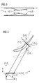
- FIG. 1 shows three blades arranged in a row adjacent to each other. Shown is a geometric model of a blade profile for each of the three blades.
- the mean blade profile is as a reference blade profile R and the two to the reference blade profile R adjacent blade profiles are designated as a first adjacent blade profile +1 and a second adjacent blade profile -1.
- Each of the airfoils R, -1, +1 has a leading edge 1 and a trailing edge 2, respectively.
- a channel 3 is arranged, in which a working fluid flows during operation of the axial flow machine.
- the solid lines in FIG. 1 The blade profiles represent R, +1, -1 in their stopped state.
- the dashed lines represent the vibration of the blade profiles R, +1, -1, with the first adjacent blade profile +1 and the second adjacent blade profile -1 being the same Have oscillation phase, which is offset to the oscillation phase of the reference blade profile R.
- the geometric model of the blade profile R, -1, +1 is provided, the blade profiles R, -1, +1 being identical in a row of blades.
- a step b) becomes the waveform ⁇ of the geometric model.
- the mode of oscillation then results as a superimposition of these two forms.
- this superposition is shown in a phasor diagram 4, wherein the phase offset between the real part and the imaginary part is denoted by ⁇ .
- a c and a s can be determined by means of a finite element structure solver, wherein the finite element structure solver receives as an input the vane profile.
- x is a coordinate on the surface of one of the two adjacent blade profiles and t is the time.
- the location-dependent perturbation pressure p ( x , t) in the channel 3 proportional to the size of an area A ( x , t) which extends in the channel and is disposed on the channel 3 bounding blade surfaces perpendicular to these blade surfaces and therebetween perpendicular to the flow lines.
- the approximation that the perturbation pressure p ( x , t) as being proportional to the area A ( x , t) is assumed to be in FIG. 3 illustrated.
- the solid lines in FIG. 3 The two dashed lines delimiting the channel 3 represent their resting state.
- the dashed lines represent the two blade surfaces delimiting the channel 3 with a deflection during their oscillation.
- a small area A FOG. x , t
- the speed of the working fluid is high during operation of the axial-flow machine, whereby a low perturbation pressure p ( x , t) prevails.
- the speed of the working fluid is low, whereby a high perturbation pressure p ( x , t) prevails.
- a 0 ( x ) the area A ( x , t) is at standstill blade profiles.
- a 0 ( x ) can, as in FIG. 1 shown to be determined by the coordinate x on the blade surface of a blade profile, a circle 12 is found, which is the blade surface of a blade profile at the coordinate x and the blade surface of the other blade profile is tangent in one point.
- the circle 12 with the shortest diameter is selected.
- a 0 ( x ) is then chosen such that A 0 ( x ) from the normal n R on the surface of the one blade profile at the coordinate x and from the normal n 1 is tangent to the surface of the other blade profile at the point.
- a 0 ( x ) determined by interpolating a function between the coordinate x and the point.
- the function may be a second order polynomial. As it is from fig 1, both have normal n R and n 1 on the circle center 11 of the circle 12, which is a consequence of the fact that the circle 12 the two blade surfaces in the coordinate x and tangent to the point.
- R
- R is the projection of the waveform ⁇ to the normal n R of the blade surface at the coordinate x for the one blade profile.
- 1
- 1 is the projection of the waveform ⁇ to the normal n 1 of the blade surface at the point on the blade surface of the other blade profile.
- the respective projections ⁇ R and ⁇ 1 are in FIG. 2 as the lines from the respective point to the respective end of the lines.
- ⁇ 1 and ⁇ R are the respective phase offset between the imaginary part and the real part.
- ⁇ is the phase offset of the oscillations of the two blade profiles and ⁇ is the angular frequency.
- a step d the attenuation of the oscillation caused by the disturbance pressure profile is determined.
- the disturbance pressure is multiplied by the projection of the waveform on the normal of the blade surface.
- the resulting product is integrated over the entire channel 3, resulting in the attenuation.
- step d the geometric model is changed and a modified waveform for the modified geometric model is determined.
- step c) is carried out with the modified geometric model and the changed waveform.
- a step e the damping of the oscillation is determined by the interference pressure profile p (calculated in step d). x , t) determined.
- the modified geometric model is accepted in the event that the damping of the vibration is stronger than in step c), otherwise steps d) and e) are repeated with another modified geometric model.
- step d) the damping of the vibration for different values for ⁇ 1 , ⁇ R and ⁇ is determined, so that the time dependence of the area A ( x , t) received.
- step f numerically calculating the oscillation of the geometric model accepted in step e) and calculating the damping of the oscillation takes place.
- the interference pressure p (calculated in step c) x , t) and the attenuation calculated in step d) represent an approximation for the case k ⁇ 0, where k is the reduced frequency.
- f is the frequency of the vibration
- c is the chord length of the blade profile
- U is the velocity of the working fluid in an axial position of the turbomachine in which the leading edges 1 of the blade profiles lie.
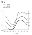
- the attenuation curve calculated in step f) is shown over a period of oscillation for different reduced frequencies k .
- the geometric model underlying step f) is a geometric model accepted in step e).
- the attenuation value profile 8 is comparable to that determined in step d) on account of its less reduced frequency. It can be seen that with increasing reduced frequency the damping of the oscillation increases.
- the geometric model accepted in step e) thus provides a good starting point for the subsequent numerical simulation of the vibration.
Abstract
Die Erfindung betrifft ein Verfahren zum Profilieren von Schaufeln einer Axialströmungsmaschine, mit den Schritten: a) Bereitstellen eines geometrischen Modells eines Schaufelprofils (R, -1, +1); b) Ermitteln einer Schwingungsform des geometrischen Modells; c) Berechnen eines zeitlichen Verlaufs eines ortsabhängigen Stördrucks p( x ,t) in einem Kanal (3) zwischen zwei benachbart angeordneten Schaufelprofilen über eine Schwingungsperiode der zu der Schwingungsform gehörigen Schwingung, wobei zum Berechnen des Verlaufs angenommen wird, dass der ortsabhängige Stördruck p( x ,t) in dem Kanal (3) proportional zu der Größe einer Fläche A( x ,t) ist, die in dem Kanal sich erstreckt und auf den den Kanal (3) begrenzenden Schaufeloberflächen senkrecht zu diesen Schaufeloberflächen und dazwischen senkrecht zu den Strömungslinien angeordnet ist, wobei x eine Koordinate auf der Schaufeloberfläche und t die Zeit ist; d) Bestimmen der durch den Stördruckverlauf hervorgerufenen Dämpfung der Schwingung; d) Verändern des geometrischen Modells und ermitteln einer veränderten Schwingungsform für das veränderte geometrische Modell sowie Durchführen von Schritt c) mit dem veränderten geometrischen Modell und der veränderten Schwingungsform; e) Bestimmen der Dämpfung der Schwingung durch den in Schritt d) berechneten Stördruckverlauf p( x ,t) und Akzeptieren des veränderten geometrischen Modells für den Fall, dass die Dämpfung der Schwingung stärker als in Schritt c) ausfällt, ansonsten Wiederholen der Schritte d) und e) mit einem anderen veränderten geometrischen Modell.The invention relates to a method for profiling blades of an axial flow machine, comprising the steps of: a) providing a geometric model of a blade profile (R, -1, +1); b) determining a waveform of the geometric model; c) calculating a time profile of a location-dependent perturbation pressure p (x, t) in a channel (3) between two adjacently arranged blade profiles over a period of oscillation of the oscillation belonging to the oscillation form, it being assumed for calculating the profile that the location-dependent interference pressure p ( x, t) in the channel (3) is proportional to the size of a surface A (x, t) extending in the channel and on the channel surfaces bounding the channel (3) perpendicular to these blade surfaces and therebetween perpendicular to the flow lines where x is a coordinate on the blade surface and t is the time; d) determining the induced by the Stördruckverlauf attenuation of the vibration; d) changing the geometric model and determining an altered waveform for the modified geometric model and performing step c) with the modified geometric model and the modified waveform; e) determining the damping of the vibration by the perturbation curve p (x, t) calculated in step d) and accepting the modified geometric model in the event that the damping of the vibration fails more than in step c), otherwise repeating steps d) and e) with another modified geometric model.
Description
Die Erfindung betrifft ein Verfahren zum Profilieren von Schaufeln einer Axialströmungsmaschine.The invention relates to a method for profiling of blades of an axial flow machine.
Der Trend bei der Auslegung von Schaufeln für eine Axialströmungsmaschine geht dahin, das Aspektverhältnis der Schaufeln zu erhöhen und die Schaufeln dünner auszuführen. Die derart ausgelegten Schaufeln neigen dazu im Betrieb der Axialströmungsmaschine zu flattern. Bei dem Flattern handelt es sich um eine selbsterregte Schwingung bei der Eigenfrequenz der Schaufel. Bei dieser Schwingung kann es sich um eine Longitudinalschwingung der Schaufel mit einem Schwingungsknoten an dem Fuß der Schaufel handeln. Dabei wird Energie von dem in der Axialströmungsmaschine strömenden Fluid auf die Schaufel übertragen. Das Flattern kann bei einem wiederholten Lastwechsel der Axialströmungsmaschine zu einer Materialermüdung der Schaufel führen (englisch: high cycle fatigue). Die Materialermüdung kann zu der Bildung eines Risses führen und einen kostenintensiven Tausch der Schaufel erforderlich machen.The trend in the design of blades for an axial flow machine is to increase the aspect ratio of the blades and make the blades thinner. The blades designed in this way tend to flutter during operation of the axial flow machine. The flutter is a self-excited vibration at the natural frequency of the blade. This vibration may be a longitudinal vibration of the blade with a node of vibration at the root of the blade. In this case, energy is transferred from the fluid flowing in the axial flow machine to the blade. The flutter can lead to material fatigue of the blade at a repeated load change of the axial flow machine (English: high cycle fatigue). The material fatigue can lead to the formation of a crack and require a costly replacement of the blade.
Herkömmlich wird das Flattern unterbunden, indem die auf die Schaufel wirkende Last vermindert wird. Dies führt jedoch nachteilig zu einer Verminderung des Wirkungsgrades der Axialströmungsmaschine. Außerdem werden herkömmlich Dämpfungselemente vorgesehen, wie beispielsweise ein Deckband, was das Flattern der Schaufeln dämpft. Dies stellt jedoch eine konstruktiv aufwändige Lösung dar. Daher wäre es wünschenswert die Schaufel derart auszulegen, dass sie im Betrieb der Axialströmungsmaschine nicht zum Flattern neigt.Conventionally, the chatter is inhibited by reducing the load on the bucket. However, this leads disadvantageously to a reduction in the efficiency of the axial flow machine. In addition, conventional damping elements are provided, such as a shroud, which dampens the flutter of the blades. However, this represents a structurally complex solution. Therefore, it would be desirable to design the blade such that it does not tend to flutter during operation of the axial flow machine.
Herkömmlich wird die Schaufel derart ausgelegt, dass in einem Vorauslegungsverfahren zuerst ein Schaufelprofil hinsichtlich der reduzierten Frequenz und des 0D Strouhal Kriteriums bewertet wird. Nach dem Vorauslegungsverfahren werden die akzeptierten Schaufelprofile in einer aufwändigen numerischen Schwingungssimulation bewertet. Die anhand der reduzierten Frequenz und des Strouhal Kriteriums bewerteten akzeptierten Schaufelprofile weisen jedoch in der Schwingungssimulation oftmals ein unakzeptables Flatterverhalten auf. Dies führt dazu, dass für viele verschiedene Schaufelprofile das Vorauslegungsverfahren und die numerische Schwingungssimulation wiederholt werden muss, was zeitaufwändig und kostenintensiv ist.Conventionally, the bucket is designed such that in a pre-fabricating process, a bucket profile is first evaluated for reduced frequency and 0D Strouhal criterion. After the prediction procedure, the accepted Vane profiles evaluated in a complex numerical vibration simulation. However, the accepted blade profiles evaluated on the basis of the reduced frequency and the Strouhal criterion often have an unacceptable flutter behavior in the vibration simulation. As a result, for many different blade profiles, the pre-lay and numerical vibration simulation must be repeated, which is time consuming and costly.
Aufgabe der Erfindung ist es daher, ein Verfahren zum Profilieren einer Schaufel einer Axialströmungsmaschine zu schaffen, welches wenig zeitaufwändig und wenig kostenintensiv ist.The object of the invention is therefore to provide a method for profiling a blade of an axial flow machine, which is less time-consuming and less expensive.
Das erfindungsgemäße Verfahren zum Profilieren von Schaufeln einer Axialströmungsmaschine weist die Schritte auf: a) Bereitstellen eines geometrischen Modells eines Schaufelprofils; b) Ermitteln einer Schwingungsform des geometrischen Modells; c) Berechnen eines zeitlichen Verlaufs eines ortsabhängigen Stördrucks p(
Insbesondere aufgrund der Annahme, dass der Stördruck in dem Kanal proportional zu der Fläche A(
Bevorzugt weist das Verfahren den Schritt auf: f) Numerisches Berechnen der anhand einer Strömung hervorgerufenen Schwingung des in Schritt e) akzeptierten geometrischen Modells und Berechnen der Dämpfung der Schwingung. Bei dem Verfahrensschritt f) handelt es um die vorgenannte numerische Schwingungssimulation. Die hier berechnete Dämpfung der Schwingung ist genauer als die in dem Verfahrensschritt d) bestimmte. Es ist hierbei bevorzugt, dass in dem Schritt f) die Konvektion und die Trägheit der Strömung berücksichtigt werden. Dadurch kann die Genauigkeit bei der Bestimmung der Dämpfung noch weiter gesteigert werden.Preferably, the method comprises the step of: f) numerically calculating the flow-induced vibration of the geometric model accepted in step e) and calculating the damping of the vibration. The method step f) is the aforementioned numerical vibration simulation. The attenuation of the oscillation calculated here is more accurate than that determined in method step d). It is preferred here that in step f) the convection and the inertia of the flow are taken into account. As a result, the accuracy in determining the damping can be further increased.
Es ist bevorzugt, dass die Schwingungsform in komplexer Form dargestellt wird:
Es ist bevorzugt, dass A(![]()
![]()
![]()
![]()
Es ist bevorzugt, dass A0(
Es ist bevorzugt, dass in Schritt d) die Dämpfung der Schwingung für verschiedene Werte für β 1, βR und σ bestimmt wird. Dadurch lässt sich die Zeitabhängigkeit der Fläche A0(
Im Folgenden wird anhand der beigefügten schematischen Zeichnungen die Erfindung näher erläutert. Es zeigen
-
Figur 1 -
Figur 2 ein Detail ausFigur 1 -
Figur 3 -
Figur 4 -
Figur 5 einen Dämpfungsverlauf über eine Schwingungsperiode für verschiedene reduzierte Frequenzen.
-
FIG. 1 a cross section through three adjacently arranged blades, -
FIG. 2 a detail fromFIG. 1 . -
FIG. 3 a representation of a channel between two adjacent arranged blades, -
FIG. 4 a representation of a waveform of a blade and -
FIG. 5 an attenuation curve over a period of oscillation for different reduced frequencies.
Eine Axialströmungsmaschine, wie beispielsweise eine Gasturbine oder eine Dampfturbine, weist Reihen von Schaufeln auf. Bei den Schaufeln kann es sich um Leitschaufeln und/oder Laufschaufeln handeln, die in einem Verdichter und/oder in einer Turbine angeordnet sind.
In dem Verfahren zum Profilieren der Schaufel wird in einem Schritt a) das geometrische Modell des Schaufelprofils R, -1, +1 bereitgestellt, wobei die Schaufelprofile R, -1, +1 in einer Reihe von Schaufeln identisch sind.In the method for profiling the blade, in a step a), the geometric model of the blade profile R, -1, +1 is provided, the blade profiles R, -1, +1 being identical in a row of blades.
In einem Schritt b) wird die Schwingungsform
In einem Schritt c) wird ein zeitlicher Verlauf eines ortsabhängigen Stördrucks p(
Die Näherung, dass der Stördruck p(
A(![]()
![]()
![]()
![]()
ÂR = |
In einem Schritt d) wird die durch den Stördruckverlauf hervorgerufenen Dämpfung der Schwingung bestimmt. Dazu wird der Stördruck mit der Projektion der Schwingungsform auf die Normale der Schaufeloberfläche multipliziert. Das dabei erhaltene Produkt wird über den gesamten Kanal 3 integriert, wodurch sich die Dämpfung ergibt.In a step d), the attenuation of the oscillation caused by the disturbance pressure profile is determined. For this purpose, the disturbance pressure is multiplied by the projection of the waveform on the normal of the blade surface. The resulting product is integrated over the
In einem Schritt d) wird das geometrische Modell verändert und eine veränderte Schwingungsform für das veränderte geometrische Modell ermittelt. In dem Schritt d) wird zudem Schritt c) mit dem veränderten geometrischen Modell und der veränderten Schwingungsform durchgeführt.In a step d), the geometric model is changed and a modified waveform for the modified geometric model is determined. In step d), in addition, step c) is carried out with the modified geometric model and the changed waveform.
In einem Schritt e) wird die Dämpfung der Schwingung durch den in Schritt d) berechneten Stördruckverlauf p(
In Schritt d) kann die Dämpfung der Schwingung für verschiedene Werte für β 1, βR und σ bestimmt wird, so dass die Zeitabhängigkeit der Fläche A(
In einem Schritt f) erfolgt ein numerisches Berechnen der anhand einer Strömung hervorgerufenen Schwingung des in Schritt e) akzeptierten geometrischen Modells und ein Berechnen der Dämpfung der Schwingung.In a step f), numerically calculating the oscillation of the geometric model accepted in step e) and calculating the damping of the oscillation takes place.
Der in Schritt c) berechnete Stördruck p(
Obwohl die Erfindung im Detail durch das bevorzugte Ausführungsbeispiel näher illustriert und beschrieben wurde, so ist die Erfindung nicht durch die offenbarten Beispiele eingeschränkt und andere Variationen können vom Fachmann hieraus abgeleitet werden, ohne den Schutzumfang der Erfindung zu verlassen.Although the invention has been further illustrated and described in detail by the preferred embodiment, the invention is not limited by the disclosed examples, and other variations can be derived therefrom by those skilled in the art without departing from the scope of the invention.
Claims (10)
wobei in Schritt f) die Konvektion und die Trägheit der Strömung berücksichtigt werden.Method according to claim 2,
wherein in step f) the convection and the inertia of the flow are taken into account.
wobei die Schwingungsform in komplexer Form dargestellt wird:
wherein the waveform is represented in a complex form:
wobei
in which
wobei
in which
wobei A0(
where A 0 (
wobei A0(
where A 0 (
wobei in Schritt d) die Dämpfung der Schwingung für verschiedene Werte für β 1, βR und σ bestimmt wird.Method according to one of claims 6 to 8,
wherein in step d) the damping of the vibration is determined for different values for β 1 , β R and σ .
wobei in Schritt d) eine Integration des ortsabhängigen Stördrucks entlang des vollständigen Kanals (3) vorgenommen wird.Method according to one of claims 1 to 9,
wherein in step d) an integration of the location-dependent Stördrucks along the complete channel (3) is made.
Priority Applications (5)
| Application Number | Priority Date | Filing Date | Title |
|---|---|---|---|
| EP16167260.5A EP3239460A1 (en) | 2016-04-27 | 2016-04-27 | Method for profiling blades of an axial turbo machine |
| JP2018556405A JP6807950B2 (en) | 2016-04-27 | 2017-04-12 | Methods for contouring the blades of axial turbomachinery |
| US16/093,312 US11365637B2 (en) | 2016-04-27 | 2017-04-12 | Method for profiling blades of an axial turbomachine |
| EP17717160.0A EP3426895B1 (en) | 2016-04-27 | 2017-04-12 | Method for profiling blades of an axial turbomachine |
| PCT/EP2017/058776 WO2017186492A1 (en) | 2016-04-27 | 2017-04-12 | Method for profiling blades of an axial turbomachine |
Applications Claiming Priority (1)
| Application Number | Priority Date | Filing Date | Title |
|---|---|---|---|
| EP16167260.5A EP3239460A1 (en) | 2016-04-27 | 2016-04-27 | Method for profiling blades of an axial turbo machine |
Publications (1)
| Publication Number | Publication Date |
|---|---|
| EP3239460A1 true EP3239460A1 (en) | 2017-11-01 |
Family
ID=55910131
Family Applications (2)
| Application Number | Title | Priority Date | Filing Date |
|---|---|---|---|
| EP16167260.5A Withdrawn EP3239460A1 (en) | 2016-04-27 | 2016-04-27 | Method for profiling blades of an axial turbo machine |
| EP17717160.0A Active EP3426895B1 (en) | 2016-04-27 | 2017-04-12 | Method for profiling blades of an axial turbomachine |
Family Applications After (1)
| Application Number | Title | Priority Date | Filing Date |
|---|---|---|---|
| EP17717160.0A Active EP3426895B1 (en) | 2016-04-27 | 2017-04-12 | Method for profiling blades of an axial turbomachine |
Country Status (4)
| Country | Link |
|---|---|
| US (1) | US11365637B2 (en) |
| EP (2) | EP3239460A1 (en) |
| JP (1) | JP6807950B2 (en) |
| WO (1) | WO2017186492A1 (en) |
Cited By (1)
| Publication number | Priority date | Publication date | Assignee | Title |
|---|---|---|---|---|
| CN110905852A (en) * | 2019-11-26 | 2020-03-24 | 北京石油化工学院 | Three-dimensional modeling method for movable blade of dynamic adjustment axial flow fan |
Families Citing this family (1)
| Publication number | Priority date | Publication date | Assignee | Title |
|---|---|---|---|---|
| US20190107046A1 (en) * | 2017-10-05 | 2019-04-11 | General Electric Company | Turbine engine with struts |
Citations (3)
| Publication number | Priority date | Publication date | Assignee | Title |
|---|---|---|---|---|
| EP1528223A2 (en) * | 2003-10-29 | 2005-05-04 | ROLLS-ROYCE plc | Design of vanes for exposure to vibratory loading |
| US20100050594A1 (en) * | 2008-08-27 | 2010-03-04 | Snecma | Method for reducing the vibration levels of a propfan of contrarotating bladed disks of a turbine engine |
| US20140112760A1 (en) * | 2012-10-23 | 2014-04-24 | United Technologies Corporation | Reduction of equally spaced turbine nozzle vane excitation |
Family Cites Families (16)
| Publication number | Priority date | Publication date | Assignee | Title |
|---|---|---|---|---|
| US5993161A (en) * | 1997-02-21 | 1999-11-30 | California Institute Of Technology | Rotors with mistuned blades |
| JP4765223B2 (en) | 2001-08-09 | 2011-09-07 | 株式会社Ihi | Turbo type aerodynamic device and method for manufacturing the wing |
| US20060073022A1 (en) * | 2004-10-05 | 2006-04-06 | Gentile David P | Frequency tailored thickness blade for a turbomachine wheel |
| DE102005025213B4 (en) * | 2005-06-01 | 2014-05-15 | Honda Motor Co., Ltd. | Blade of an axial flow machine |
| US7497664B2 (en) * | 2005-08-16 | 2009-03-03 | General Electric Company | Methods and apparatus for reducing vibrations induced to airfoils |
| US20090155082A1 (en) * | 2007-12-18 | 2009-06-18 | Loc Duong | Method to maximize resonance-free running range for a turbine blade |
| GB0821429D0 (en) * | 2008-11-24 | 2008-12-31 | Rolls Royce Plc | A method for optimising the shape of an aerofoil |
| GB201003084D0 (en) * | 2010-02-24 | 2010-04-14 | Rolls Royce Plc | An aerofoil |
| US8135568B2 (en) | 2010-06-25 | 2012-03-13 | General Electric Company | Turbomachine airfoil life management system and method |
| FR2991373B1 (en) * | 2012-05-31 | 2014-06-20 | Snecma | BLOWER DAWN FOR AIRBORNE AIRCRAFT WITH CAMBRE PROFILE IN FOOT SECTIONS |
| EP2762678A1 (en) * | 2013-02-05 | 2014-08-06 | Siemens Aktiengesellschaft | Method for misaligning a rotor blade grid |
| GB201309280D0 (en) * | 2013-05-23 | 2013-07-10 | Rolls Royce Plc | Aerofoil Recambering |
| CN113685377A (en) * | 2014-06-24 | 2021-11-23 | 概创机械设计有限责任公司 | Flow control structure for turbomachine and design method thereof |
| US10443390B2 (en) * | 2014-08-27 | 2019-10-15 | Pratt & Whitney Canada Corp. | Rotary airfoil |
| US9879539B2 (en) * | 2014-11-18 | 2018-01-30 | Honeywell International Inc. | Engine airfoils and methods for reducing airfoil flutter |
| EP3088663A1 (en) * | 2015-04-28 | 2016-11-02 | Siemens Aktiengesellschaft | Method for profiling a blade |
-
2016
- 2016-04-27 EP EP16167260.5A patent/EP3239460A1/en not_active Withdrawn
-
2017
- 2017-04-12 EP EP17717160.0A patent/EP3426895B1/en active Active
- 2017-04-12 US US16/093,312 patent/US11365637B2/en active Active
- 2017-04-12 WO PCT/EP2017/058776 patent/WO2017186492A1/en active Application Filing
- 2017-04-12 JP JP2018556405A patent/JP6807950B2/en active Active
Patent Citations (3)
| Publication number | Priority date | Publication date | Assignee | Title |
|---|---|---|---|---|
| EP1528223A2 (en) * | 2003-10-29 | 2005-05-04 | ROLLS-ROYCE plc | Design of vanes for exposure to vibratory loading |
| US20100050594A1 (en) * | 2008-08-27 | 2010-03-04 | Snecma | Method for reducing the vibration levels of a propfan of contrarotating bladed disks of a turbine engine |
| US20140112760A1 (en) * | 2012-10-23 | 2014-04-24 | United Technologies Corporation | Reduction of equally spaced turbine nozzle vane excitation |
Cited By (1)
| Publication number | Priority date | Publication date | Assignee | Title |
|---|---|---|---|---|
| CN110905852A (en) * | 2019-11-26 | 2020-03-24 | 北京石油化工学院 | Three-dimensional modeling method for movable blade of dynamic adjustment axial flow fan |
Also Published As
| Publication number | Publication date |
|---|---|
| JP2019515178A (en) | 2019-06-06 |
| WO2017186492A1 (en) | 2017-11-02 |
| EP3426895B1 (en) | 2020-02-05 |
| JP6807950B2 (en) | 2021-01-06 |
| EP3426895A1 (en) | 2019-01-16 |
| US11365637B2 (en) | 2022-06-21 |
| US20190203601A1 (en) | 2019-07-04 |
Similar Documents
| Publication | Publication Date | Title |
|---|---|---|
| EP3274558B1 (en) | Method for profiling a turbine blade and corresponding blade | |
| DE102009003793A1 (en) | Shape of a shroud of a turbine blade | |
| EP1716315B1 (en) | Method for producing adapted flow surfaces | |
| CH708644A2 (en) | Scaling method for custom sized turbomachinery blades. | |
| DE102005014871A1 (en) | Blade mold design program and method | |
| EP1532419B1 (en) | Coordinate measuring device and method for measuring a workpiece | |
| EP3428396A1 (en) | Method for generating and selecting a detuning pattern of an impeller of a turbomachine having a plurality of rotor blades | |
| EP2787182A1 (en) | Guide blade for a fluid flow engine, guide blade grid and method for the production of a guide blade or a guide blade grid | |
| DE102012113167A1 (en) | Method and apparatus for obtaining discrete axial performance data using radial clearance sensors | |
| EP3404210A1 (en) | Blade cascade segment for a turbomachine with non-axisymmetric platform surface, corresponding blade cascade, blade channel, platform, and turbomachine | |
| EP3426895B1 (en) | Method for profiling blades of an axial turbomachine | |
| DE102018210894A1 (en) | Design and manufacture of a turbomachine blade | |
| EP2805017B1 (en) | Guide blade assembly for an axial flow machine and method for laying the guide blade assembly | |
| DE102018115354A1 (en) | Device and method for determining at least one rotation parameter of a rotating device | |
| EP2275647A2 (en) | Flow working machine with rotor series group | |
| DE102012104240A1 (en) | Hybrid flow blade design | |
| EP2912272B1 (en) | Method for misaligning a rotor blade grid | |
| DE102014110315A1 (en) | A blade positioning | |
| CH706969A2 (en) | A process for the circumferential orientation of blades of a turbine by reshaping the downstream blades of the turbine. | |
| DE102016221928A1 (en) | Method for operating a cyclically loaded component during operation | |
| EP3590632B1 (en) | Blade assembly for a gas turbine and method for producing said assembly | |
| DE112019004838T5 (en) | Turbine rotor blade, turbine and blade gap measurement method | |
| DE2043083B2 (en) | Method and blading to reduce the winding movement of a mass particle when flowing through a turbo machine | |
| EP3362648B1 (en) | Method for producing a base part of a turbine blade | |
| EP1256857B1 (en) | Method for generating a data-validation model of an installation from a simulation model of the installation |
Legal Events
| Date | Code | Title | Description |
|---|---|---|---|
| PUAI | Public reference made under article 153(3) epc to a published international application that has entered the european phase |
Free format text: ORIGINAL CODE: 0009012 |
|
| AK | Designated contracting states |
Kind code of ref document: A1 Designated state(s): AL AT BE BG CH CY CZ DE DK EE ES FI FR GB GR HR HU IE IS IT LI LT LU LV MC MK MT NL NO PL PT RO RS SE SI SK SM TR |
|
| AX | Request for extension of the european patent |
Extension state: BA ME |
|
| STAA | Information on the status of an ep patent application or granted ep patent |
Free format text: STATUS: THE APPLICATION IS DEEMED TO BE WITHDRAWN |
|
| 18D | Application deemed to be withdrawn |
Effective date: 20180503 |