KR20230028251A - Machine tools, machine tool control methods - Google Patents
Machine tools, machine tool control methods Download PDFInfo
- Publication number
- KR20230028251A KR20230028251A KR1020227041591A KR20227041591A KR20230028251A KR 20230028251 A KR20230028251 A KR 20230028251A KR 1020227041591 A KR1020227041591 A KR 1020227041591A KR 20227041591 A KR20227041591 A KR 20227041591A KR 20230028251 A KR20230028251 A KR 20230028251A
- Authority
- KR
- South Korea
- Prior art keywords
- workpiece
- spindle
- main shaft
- seam
- amount
- Prior art date
Links
- 238000000034 method Methods 0.000 title claims abstract description 32
- 238000006073 displacement reaction Methods 0.000 claims abstract description 88
- 238000003466 welding Methods 0.000 claims abstract description 34
- 238000001514 detection method Methods 0.000 claims description 9
- 230000003287 optical effect Effects 0.000 claims description 7
- 238000013459 approach Methods 0.000 claims description 4
- 238000003825 pressing Methods 0.000 claims description 4
- 230000003247 decreasing effect Effects 0.000 claims description 2
- 230000007246 mechanism Effects 0.000 description 10
- 238000010586 diagram Methods 0.000 description 9
- 238000005304 joining Methods 0.000 description 8
- 230000007423 decrease Effects 0.000 description 6
- 238000012937 correction Methods 0.000 description 4
- 238000005520 cutting process Methods 0.000 description 4
- 238000004519 manufacturing process Methods 0.000 description 3
- 238000012790 confirmation Methods 0.000 description 2
- 230000008030 elimination Effects 0.000 description 2
- 238000003379 elimination reaction Methods 0.000 description 2
- 230000006641 stabilisation Effects 0.000 description 2
- 238000011105 stabilization Methods 0.000 description 2
- 230000007723 transport mechanism Effects 0.000 description 2
- 230000000694 effects Effects 0.000 description 1
- 230000007613 environmental effect Effects 0.000 description 1
- 238000002474 experimental method Methods 0.000 description 1
- 230000006870 function Effects 0.000 description 1
- 238000003754 machining Methods 0.000 description 1
- 238000005259 measurement Methods 0.000 description 1
- 238000012546 transfer Methods 0.000 description 1
Images


Classifications
-
- B—PERFORMING OPERATIONS; TRANSPORTING
- B23—MACHINE TOOLS; METAL-WORKING NOT OTHERWISE PROVIDED FOR
- B23K—SOLDERING OR UNSOLDERING; WELDING; CLADDING OR PLATING BY SOLDERING OR WELDING; CUTTING BY APPLYING HEAT LOCALLY, e.g. FLAME CUTTING; WORKING BY LASER BEAM
- B23K20/00—Non-electric welding by applying impact or other pressure, with or without the application of heat, e.g. cladding or plating
- B23K20/12—Non-electric welding by applying impact or other pressure, with or without the application of heat, e.g. cladding or plating the heat being generated by friction; Friction welding
- B23K20/122—Non-electric welding by applying impact or other pressure, with or without the application of heat, e.g. cladding or plating the heat being generated by friction; Friction welding using a non-consumable tool, e.g. friction stir welding
- B23K20/123—Controlling or monitoring the welding process
-
- G—PHYSICS
- G05—CONTROLLING; REGULATING
- G05B—CONTROL OR REGULATING SYSTEMS IN GENERAL; FUNCTIONAL ELEMENTS OF SUCH SYSTEMS; MONITORING OR TESTING ARRANGEMENTS FOR SUCH SYSTEMS OR ELEMENTS
- G05B19/00—Programme-control systems
- G05B19/02—Programme-control systems electric
- G05B19/18—Numerical control [NC], i.e. automatically operating machines, in particular machine tools, e.g. in a manufacturing environment, so as to execute positioning, movement or co-ordinated operations by means of programme data in numerical form
- G05B19/404—Numerical control [NC], i.e. automatically operating machines, in particular machine tools, e.g. in a manufacturing environment, so as to execute positioning, movement or co-ordinated operations by means of programme data in numerical form characterised by control arrangements for compensation, e.g. for backlash, overshoot, tool offset, tool wear, temperature, machine construction errors, load, inertia
-
- B—PERFORMING OPERATIONS; TRANSPORTING
- B23—MACHINE TOOLS; METAL-WORKING NOT OTHERWISE PROVIDED FOR
- B23K—SOLDERING OR UNSOLDERING; WELDING; CLADDING OR PLATING BY SOLDERING OR WELDING; CUTTING BY APPLYING HEAT LOCALLY, e.g. FLAME CUTTING; WORKING BY LASER BEAM
- B23K20/00—Non-electric welding by applying impact or other pressure, with or without the application of heat, e.g. cladding or plating
- B23K20/12—Non-electric welding by applying impact or other pressure, with or without the application of heat, e.g. cladding or plating the heat being generated by friction; Friction welding
- B23K20/1205—Non-electric welding by applying impact or other pressure, with or without the application of heat, e.g. cladding or plating the heat being generated by friction; Friction welding using translation movement
-
- B—PERFORMING OPERATIONS; TRANSPORTING
- B23—MACHINE TOOLS; METAL-WORKING NOT OTHERWISE PROVIDED FOR
- B23K—SOLDERING OR UNSOLDERING; WELDING; CLADDING OR PLATING BY SOLDERING OR WELDING; CUTTING BY APPLYING HEAT LOCALLY, e.g. FLAME CUTTING; WORKING BY LASER BEAM
- B23K20/00—Non-electric welding by applying impact or other pressure, with or without the application of heat, e.g. cladding or plating
- B23K20/12—Non-electric welding by applying impact or other pressure, with or without the application of heat, e.g. cladding or plating the heat being generated by friction; Friction welding
- B23K20/121—Control circuits therefor
-
- B—PERFORMING OPERATIONS; TRANSPORTING
- B23—MACHINE TOOLS; METAL-WORKING NOT OTHERWISE PROVIDED FOR
- B23K—SOLDERING OR UNSOLDERING; WELDING; CLADDING OR PLATING BY SOLDERING OR WELDING; CUTTING BY APPLYING HEAT LOCALLY, e.g. FLAME CUTTING; WORKING BY LASER BEAM
- B23K20/00—Non-electric welding by applying impact or other pressure, with or without the application of heat, e.g. cladding or plating
- B23K20/12—Non-electric welding by applying impact or other pressure, with or without the application of heat, e.g. cladding or plating the heat being generated by friction; Friction welding
- B23K20/122—Non-electric welding by applying impact or other pressure, with or without the application of heat, e.g. cladding or plating the heat being generated by friction; Friction welding using a non-consumable tool, e.g. friction stir welding
- B23K20/1245—Non-electric welding by applying impact or other pressure, with or without the application of heat, e.g. cladding or plating the heat being generated by friction; Friction welding using a non-consumable tool, e.g. friction stir welding characterised by the apparatus
- B23K20/125—Rotary tool drive mechanism
-
- B—PERFORMING OPERATIONS; TRANSPORTING
- B23—MACHINE TOOLS; METAL-WORKING NOT OTHERWISE PROVIDED FOR
- B23K—SOLDERING OR UNSOLDERING; WELDING; CLADDING OR PLATING BY SOLDERING OR WELDING; CUTTING BY APPLYING HEAT LOCALLY, e.g. FLAME CUTTING; WORKING BY LASER BEAM
- B23K20/00—Non-electric welding by applying impact or other pressure, with or without the application of heat, e.g. cladding or plating
- B23K20/12—Non-electric welding by applying impact or other pressure, with or without the application of heat, e.g. cladding or plating the heat being generated by friction; Friction welding
- B23K20/122—Non-electric welding by applying impact or other pressure, with or without the application of heat, e.g. cladding or plating the heat being generated by friction; Friction welding using a non-consumable tool, e.g. friction stir welding
- B23K20/1245—Non-electric welding by applying impact or other pressure, with or without the application of heat, e.g. cladding or plating the heat being generated by friction; Friction welding using a non-consumable tool, e.g. friction stir welding characterised by the apparatus
- B23K20/1255—Tools therefor, e.g. characterised by the shape of the probe
-
- B—PERFORMING OPERATIONS; TRANSPORTING
- B23—MACHINE TOOLS; METAL-WORKING NOT OTHERWISE PROVIDED FOR
- B23Q—DETAILS, COMPONENTS, OR ACCESSORIES FOR MACHINE TOOLS, e.g. ARRANGEMENTS FOR COPYING OR CONTROLLING; MACHINE TOOLS IN GENERAL CHARACTERISED BY THE CONSTRUCTION OF PARTICULAR DETAILS OR COMPONENTS; COMBINATIONS OR ASSOCIATIONS OF METAL-WORKING MACHINES, NOT DIRECTED TO A PARTICULAR RESULT
- B23Q1/00—Members which are comprised in the general build-up of a form of machine, particularly relatively large fixed members
- B23Q1/70—Stationary or movable members for carrying working-spindles for attachment of tools or work
-
- B—PERFORMING OPERATIONS; TRANSPORTING
- B23—MACHINE TOOLS; METAL-WORKING NOT OTHERWISE PROVIDED FOR
- B23Q—DETAILS, COMPONENTS, OR ACCESSORIES FOR MACHINE TOOLS, e.g. ARRANGEMENTS FOR COPYING OR CONTROLLING; MACHINE TOOLS IN GENERAL CHARACTERISED BY THE CONSTRUCTION OF PARTICULAR DETAILS OR COMPONENTS; COMBINATIONS OR ASSOCIATIONS OF METAL-WORKING MACHINES, NOT DIRECTED TO A PARTICULAR RESULT
- B23Q17/00—Arrangements for observing, indicating or measuring on machine tools
- B23Q17/22—Arrangements for observing, indicating or measuring on machine tools for indicating or measuring existing or desired position of tool or work
-
- G—PHYSICS
- G05—CONTROLLING; REGULATING
- G05B—CONTROL OR REGULATING SYSTEMS IN GENERAL; FUNCTIONAL ELEMENTS OF SUCH SYSTEMS; MONITORING OR TESTING ARRANGEMENTS FOR SUCH SYSTEMS OR ELEMENTS
- G05B19/00—Programme-control systems
- G05B19/02—Programme-control systems electric
- G05B19/18—Numerical control [NC], i.e. automatically operating machines, in particular machine tools, e.g. in a manufacturing environment, so as to execute positioning, movement or co-ordinated operations by means of programme data in numerical form
- G05B19/401—Numerical control [NC], i.e. automatically operating machines, in particular machine tools, e.g. in a manufacturing environment, so as to execute positioning, movement or co-ordinated operations by means of programme data in numerical form characterised by control arrangements for measuring, e.g. calibration and initialisation, measuring workpiece for machining purposes
-
- B—PERFORMING OPERATIONS; TRANSPORTING
- B23—MACHINE TOOLS; METAL-WORKING NOT OTHERWISE PROVIDED FOR
- B23Q—DETAILS, COMPONENTS, OR ACCESSORIES FOR MACHINE TOOLS, e.g. ARRANGEMENTS FOR COPYING OR CONTROLLING; MACHINE TOOLS IN GENERAL CHARACTERISED BY THE CONSTRUCTION OF PARTICULAR DETAILS OR COMPONENTS; COMBINATIONS OR ASSOCIATIONS OF METAL-WORKING MACHINES, NOT DIRECTED TO A PARTICULAR RESULT
- B23Q2717/00—Arrangements for indicating or measuring
- B23Q2717/003—Arrangements for indicating or measuring in lathes
-
- B—PERFORMING OPERATIONS; TRANSPORTING
- B23—MACHINE TOOLS; METAL-WORKING NOT OTHERWISE PROVIDED FOR
- B23Q—DETAILS, COMPONENTS, OR ACCESSORIES FOR MACHINE TOOLS, e.g. ARRANGEMENTS FOR COPYING OR CONTROLLING; MACHINE TOOLS IN GENERAL CHARACTERISED BY THE CONSTRUCTION OF PARTICULAR DETAILS OR COMPONENTS; COMBINATIONS OR ASSOCIATIONS OF METAL-WORKING MACHINES, NOT DIRECTED TO A PARTICULAR RESULT
- B23Q2735/00—Control systems or devices for copying from a pattern or master model
- B23Q2735/02—Means for transforming movement of the feeler into feed movement of tool or work
- B23Q2735/06—Means for transforming movement of the feeler into feed movement of tool or work involving electrical means
- B23Q2735/062—Means for transforming movement of the feeler into feed movement of tool or work involving electrical means in a lathe
-
- G—PHYSICS
- G05—CONTROLLING; REGULATING
- G05B—CONTROL OR REGULATING SYSTEMS IN GENERAL; FUNCTIONAL ELEMENTS OF SUCH SYSTEMS; MONITORING OR TESTING ARRANGEMENTS FOR SUCH SYSTEMS OR ELEMENTS
- G05B2219/00—Program-control systems
- G05B2219/30—Nc systems
- G05B2219/45—Nc applications
- G05B2219/45146—Inertia friction welding
-
- G—PHYSICS
- G05—CONTROLLING; REGULATING
- G05B—CONTROL OR REGULATING SYSTEMS IN GENERAL; FUNCTIONAL ELEMENTS OF SUCH SYSTEMS; MONITORING OR TESTING ARRANGEMENTS FOR SUCH SYSTEMS OR ELEMENTS
- G05B2219/00—Program-control systems
- G05B2219/30—Nc systems
- G05B2219/50—Machine tool, machine tool null till machine tool work handling
- G05B2219/50152—Align axis cylinder, tube with rotation axis machine
Landscapes
- Engineering & Computer Science (AREA)
- Mechanical Engineering (AREA)
- Human Computer Interaction (AREA)
- Manufacturing & Machinery (AREA)
- Physics & Mathematics (AREA)
- General Physics & Mathematics (AREA)
- Automation & Control Theory (AREA)
- Turning (AREA)
- Pressure Welding/Diffusion-Bonding (AREA)
- Automatic Control Of Machine Tools (AREA)
Abstract
마찰 접합 중에 심 어긋남의 정도를 알 수 있는 공작 기계, 공작 기계의 제어 방법을 제공한다. 제1 워크(워크(W1)로 예시)를 회전 가능하게 유지하는 제1 주축(10)과, 제1 주축에 대향 배치하여 제2 워크(워크 잔재(W2)로 예시)를 회전 가능하게 유지하는 제2 주축(20)과, 제1 워크 또는 제2 워크 중 적어도 어느 일방을 회전시키면서, 제1 주축과 제2 주축이 서로 접근하도록 상대적으로 이동시켜, 제2 워크의 후단 부분을 제1 워크의 선단 부분에 압압하여 마찰 접합시키는 제어부(40a)를 구비하는 공작 기계(자동 선반(1)으로 예시)이다. 제어부가 제1 워크에 대한 제2 워크의 심 어긋남량(s)을, 마찰 접합하고 있는 동안에 검출하는 심 어긋남량 검출 수단을 가진다. A machine tool capable of knowing the degree of seam misalignment during friction welding and a method for controlling the machine tool are provided. A first spindle 10 for rotatably holding a first workpiece (exemplified by workpiece W1), and a second workpiece (exemplified by workpiece residue W2) disposed opposite to the first spindle to rotatably hold While rotating the second spindle 20 and at least one of the first workpiece and the second workpiece, the first spindle and the second spindle are relatively moved so that they come close to each other, so that the rear end of the second workpiece is moved away from the first workpiece. It is a machine tool (exemplified by the automatic lathe 1) provided with the control part 40a which presses and friction-fits the tip part. The control unit has a seam displacement amount detecting means for detecting a seam displacement s of the second workpiece with respect to the first workpiece during friction welding.

Description
본 발명은 2개의 워크를 접합하여 1개의 워크로 하는 공작 기계, 공작 기계의 제어 방법에 관한 것이다. The present invention relates to a machine tool and a control method for a machine tool for joining two workpieces together to form one workpiece.
공작 기계에서는, 가공되지 않고 재료가 남는 경우가 있다. 재료가 남으면, 재료 코스트의 삭감이 어려워지고, 또한, 환경 보전에 공헌하기 어려워진다. 그래서, 소정의 워크와 워크의 남은 워크 잔재를 마찰 접합하는 것에 의해, 재료를 최대한 유효 활용하는 것을 생각할 수 있다. In machine tools, there are cases where material remains without being processed. If the material remains, it becomes difficult to reduce the material cost, and it becomes difficult to contribute to environmental conservation. Therefore, it is conceivable to make the most effective use of the material by friction-joining a predetermined workpiece and the remaining workpiece residue of the workpiece.
워크와 워크 잔재를 마찰 접합했을 경우, 워크와 워크 잔재와의 심 어긋남이 생기하는 경우가 있다. 그 때문에, 예를 들면, 특허문헌 1, 2에는, 마찰 접합 중에 심 어긋남이 있는지 여부를 검출하는 기술이 개시되어 있다. When a workpiece and workpiece residue are friction-joined, seam misalignment between the workpiece and workpiece residue may occur. Therefore, for example,
그렇지만, 상기 특허문헌 1, 2에 기재된 기술에서는, 마찰 접합 중에 심 어긋남의 유무를 검지할 수 있지만, 마찰 접합 중에 어느 정도 어긋나 있는지를 알 수 있는 것은 아니다. However, in the techniques described in
본 발명은 상술한 바와 같은 실정을 감안하여 이루어진 것으로, 마찰 접합 중에 심 어긋남의 정도를 알 수 있는 공작 기계, 공작 기계의 제어 방법을 제공하는 것을 목적으로 한다. The present invention has been made in view of the situation described above, and an object of the present invention is to provide a machine tool and a control method for the machine tool that can determine the degree of seam misalignment during friction welding.
본 발명은, 첫째로, 제1 워크를 회전 가능하게 유지하는 제1 주축과, 상기 제1 주축에 대향 배치하여 제2 워크를 회전 가능하게 유지하는 제2 주축과, 상기 제1 주축에 유지된 제1 워크 또는 상기 제2 주축에 유지된 상기 제2 워크 중 적어도 어느 일방을 회전시키면서, 상기 제1 주축과 상기 제2 주축이 서로 접근하도록 상대적으로 이동시켜, 상기 제2 워크의 후단 부분을 상기 제1 워크의 선단 부분에 압압(押壓)하여 마찰 접합시키는 제어부를 구비하는 공작 기계로서, 상기 제어부가, 상기 제1 워크에 대한 상기 제2 워크의 심 어긋남량을, 상기 마찰 접합하고 있는 동안에 검출하는 심 어긋남량 검출 수단을 가지는 것을 특징으로 한다. The present invention is, firstly, a first main shaft for rotatably holding a first workpiece, a second main shaft for rotatably holding a second workpiece disposed opposite to the first main shaft, and a While rotating at least one of the first work or the second work held by the second main shaft, the first main shaft and the second main shaft are relatively moved so as to approach each other, so that the rear end of the second work is A machine tool having a control unit for pressurizing and friction-welding a front end of a first workpiece, wherein the control unit measures the amount of seam displacement of the second workpiece with respect to the first workpiece during friction welding. It is characterized by having a seam displacement amount detecting means for detecting.
둘째로, 상기 심 어긋남량 검출 수단에서 검출된 상기 제1 워크에 대한 상기 제2 워크의 심 어긋남량에 기초하여, 상기 마찰 접합하고 있는 동안에, 상기 제2 주축을 상기 제2 주축의 회전 축선과 교차하는 방향으로 이동시키는 제2 주축 이동 수단을 가지는 것을 특징으로 한다. Second, based on the seam displacement amount of the second workpiece with respect to the first workpiece detected by the seam displacement amount detecting means, during the friction welding, the second spindle is aligned with the rotational axis of the second spindle. It is characterized in that it has a second main axis moving means for moving in the intersecting direction.
셋째로, 상기 제2 주축을 상기 제2 주축의 회전 축선과 교차하는 방향으로 이동하는 타이밍이, 상기 제1 주축이 회전 정지한 직후, 혹은 상기 제1 주축이 회전 정지하기 직전, 또는 상기 제1 주축의 회전 속도가 점차 감소하고 있는 동안인 것을 특징으로 한다. Thirdly, the timing of moving the second main shaft in a direction crossing the rotational axis of the second main shaft is immediately after the first main shaft stops rotating, or immediately before the first main shaft stops rotating, or the first It is characterized in that while the rotational speed of the main shaft is gradually decreasing.
넷째로, 상기 제어부가, 상기 심 어긋남량 검출 수단에서 검출한 상기 제1 워크에 대한 상기 제2 워크의 심 어긋남량과 상기 제1 주축의 회전 위상을 대조하는 것에 의해, 상기 제1 워크에 대한 상기 제2 워크의 심 어긋남 방향을, 상기 마찰 접합하고 있는 동안에 검출하는 심 어긋남 방향 검출 수단을 가지는 것을 특징으로 한다. Fourth, the control unit compares the amount of seam displacement of the second workpiece with respect to the first workpiece detected by the amount of seam displacement detection means and the rotational phase of the first spindle, so that the and a seam displacement direction detecting means for detecting the seam displacement direction of the second workpiece during the friction welding.
다섯째로, 상기 제2 주축 이동 수단이, 상기 심 어긋남량 검출 수단에서 검출된 상기 제1 워크에 대한 상기 제2 워크의 심 어긋남량과 상기 심 어긋남 방향 검출 수단에서 검출된 상기 제1 워크에 대한 상기 제2 워크의 심 어긋남 방향에 기초하여, 상기 제2 주축을, 상기 제1 워크에 대한 상기 제2 워크의 심 어긋남량이 감소하도록 상기 제2 주축의 회전 축선과 교차하는 방향으로 이동시키는 것을 특징으로 한다. Fifthly, the second main axis moving means determines the amount of seam deviation of the second workpiece with respect to the first workpiece detected by the seam deviation amount detection means and the first workpiece detected by the seam deviation direction detection means. Based on the seam displacement direction of the second workpiece, the second spindle is moved in a direction crossing the rotational axis of the second spindle so as to reduce the amount of seam displacement of the second workpiece relative to the first workpiece. to be
여섯째로, 상기 심 어긋남량 검출 수단이, 상기 제2 주축의 회전 축선과 교차하는 방향으로 상기 제2 주축을 이동시키는 모터에 걸리는 부하에 기초하여, 상기 제1 워크에 대한 상기 제2 워크의 심 어긋남량을 구하는 것을 특징으로 한다. Sixthly, the seam displacement amount detecting means determines the seam of the second workpiece relative to the first workpiece based on a load applied to a motor that moves the second main shaft in a direction intersecting the rotational axis of the second main shaft. It is characterized in that the deviation amount is obtained.
일곱째로, 상기 심 어긋남량 검출 수단이, 상기 제2 워크와의 거리를 측정하는 광학식 센서의 출력값에 기초하여, 상기 제1 워크에 대한 상기 제2 워크의 심 어긋남량을 구하는 것을 특징으로 한다. Seventhly, the seam displacement amount detecting means calculates the seam displacement amount of the second workpiece with respect to the first workpiece based on an output value of an optical sensor for measuring a distance to the second workpiece.
여덟째로, 제1 워크를 회전 가능하게 유지하는 제1 주축과, 상기 제1 주축에 대향 배치하여 상기 제1 주축으로부터 건네받은 제2 워크를 회전 가능하게 유지하는 제2 주축과, 상기 제1 주축, 및 상기 제2 주축의 동작을 제어하는 제어부를 구비하는 공작 기계의 제어 방법으로서, 상기 제1 주축에 유지된 상기 제1 워크 또는 상기 제2 주축에 유지된 상기 제2 워크 중 적어도 어느 일방을 회전시키면서, 상기 제1 주축과 상기 제2 주축이 서로 접근하도록 상대적으로 이동시켜, 상기 제2 워크의 후단 부분을 새롭게 공급된 제1 워크의 선단 부분에 접촉하여 마찰시키는 스텝과, 상기 제2 워크의 후단 부분을 상기 제1 워크의 선단 부분에 압압하여 마찰 접합하고 있는 동안에, 상기 제1 워크에 대한 상기 제2 워크의 심 어긋남량을 검출하는 스텝과, 상기 마찰 접합하고 있는 동안에, 상기 제1 워크에 대한 상기 제2 워크의 심 어긋남 방향을 검출하는 스텝과, 상기 마찰 접합하고 있는 동안에, 검출한 상기 제1 워크에 대한 상기 제2 워크의 심 어긋남량 및 검출한 상기 제1 워크에 대한 상기 제2 워크의 심 어긋남 방향에 기초하여, 상기 제2 주축을, 상기 제1 워크에 대한 상기 제2 워크의 심 어긋남량이 감소하도록 상기 제2 주축의 회전 축선과 교차하는 방향으로 이동시키는 스텝을 포함하는 것을 특징으로 한다. Eighth, a first main shaft that rotatably holds the first workpiece, a second main shaft that is disposed opposite to the first main shaft and rotatably holds the second workpiece transferred from the first main shaft, and the first main shaft , And a control method for a machine tool having a control unit for controlling the operation of the second spindle, wherein at least one of the first workpiece held on the first spindle or the second workpiece held on the second spindle While rotating, relatively moving the first main shaft and the second main shaft so that they approach each other, and contacting and rubbing the rear end portion of the second workpiece with the front end portion of the newly supplied first workpiece; A step of detecting an amount of seam displacement of the second workpiece with respect to the first workpiece during friction welding by pressing a rear end portion of the second workpiece against the front end portion of the first workpiece; A step of detecting a seam displacement direction of the second workpiece relative to the workpiece, and during the friction welding, the detected amount of seam displacement of the second workpiece relative to the first workpiece and the detected seam displacement of the second workpiece relative to the first workpiece. and moving the second spindle in a direction intersecting the rotational axis of the second workpiece so as to reduce the amount of seam displacement of the second workpiece relative to the first workpiece, based on a seam displacement direction of the second workpiece. It is characterized by doing.
본 발명은 이하의 효과를 얻을 수 있다. The present invention can obtain the following effects.
심 어긋남량 검출 수단에 의해서, 제1 워크와 제2 워크의 마찰 접합 중에, 제1 워크와 제2 워크와의 심 어긋남의 정도를 알 수 있다. 따라서, 이 마찰 접합이 끝날 때까지 원하는 작업(예를 들면 심 어긋남의 해소)을 실시할 수 있으므로, 이 마찰 접합을 실시한 후에 접합 어긋남의 확인이나, 어긋나게 접합된 워크의 수정 등을 행할 필요가 없고, 또한, 예를 들면 접합 부분의 디버링 작업 등을 신속하게 개시할 수 있다. 이 결과, 제품의 제조 코스트의 저감이나 품질 안정화를 실현할 수 있다. The degree of seam displacement between the first workpiece and the second workpiece can be known during friction welding between the first workpiece and the second workpiece by the seam misalignment amount detecting means. Therefore, since desired operations (e.g., elimination of seam misalignment) can be performed until this friction welding is completed, there is no need to check welding misalignment or correct misaligned workpieces after performing this friction welding. Furthermore, for example, the deburring operation of the joined portion can be started quickly. As a result, reduction in manufacturing cost and quality stabilization of the product can be realized.
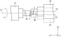
도 1은 본 발명에 따른 공작 기계의 제1 실시예인 자동 선반의 개략 구성도이다.
도 2는 심 어긋남 수정을 포함하는 동작 플로차트이다.
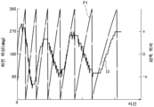
도 3은 마찰 접합에 있어서의 제1 주축의 회전 위상, X2축 모터에 공급되는 전류값을 설명하는 도면이다.
도 4는 심 어긋남에 의한 워크 잔재의 흔들림을 설명하는 도면이다.
도 5는 업셋(upset) 공정에 있어서의 제1 주축의 회전 위상, X2축 모터에 공급되는 전류값을 설명하는 도면이다.
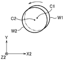
도 6a는 접합한 워크에 대한 워크 잔재의 심 어긋남을 설명하는 도면이다.
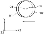
도 6b는 심 어긋남 방향을 X2축 방향에 맞추는 동작을 설명하는 도면이다.
도 6c는 심 어긋남을 해소시키는 동작을 설명하는 도면이다.
도 7은 본 발명에 따른 공작 기계의 제2 실시예인 자동 선반의 개략 구성도이다.
도 8은 제2 실시예에 있어서의 심 어긋남에 의한 워크 잔재의 흔들림을 설명하는 도면이다.
도 9는 제2 실시예의 업셋 공정에 있어서의 제1 주축의 회전 위상, 레이저 센서와 워크 잔재의 둘레측면과의 거리의 변동을 설명하는 도면이다. 1 is a schematic configuration diagram of an automatic lathe as a first embodiment of a machine tool according to the present invention.
Fig. 2 is an operation flowchart including seam misalignment correction.
Fig. 3 is a diagram explaining the rotational phase of the first main shaft in friction welding and the current value supplied to the X2-axis motor.
Fig. 4 is a view explaining the shaking of workpiece residues due to shim misalignment.
FIG. 5 is a diagram explaining the rotational phase of the first main shaft in an upset process and the current value supplied to the X2-axis motor.
Fig. 6A is a diagram explaining the seam deviation of the remaining workpiece with respect to the joined workpiece.
6B is a diagram for explaining an operation of aligning the seam displacement direction with the X2-axis direction.
6C is a diagram explaining an operation to eliminate seam misalignment.
7 is a schematic configuration diagram of an automatic lathe as a second embodiment of a machine tool according to the present invention.
Fig. 8 is a diagram explaining the shaking of workpiece residues due to core displacement in the second embodiment.
Fig. 9 is a diagram explaining variations in the rotational phase of the first main axis and the distance between the laser sensor and the circumferential surface of the workpiece residue in the upset process of the second embodiment.
실시예 1 Example 1
이하, 도면을 참조하면서 본 발명의 제1 실시예의 공작 기계, 공작 기계의 제어 방법에 대해 설명한다. Hereinafter, the machine tool and the control method of the machine tool according to the first embodiment of the present invention will be described with reference to the drawings.
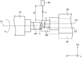
도 1에 나타내는 바와 같이, 자동 선반(공작 기계)(1)은 제1 주축(10) 및 공구대(31)를 구비하고 있다. 제1 주축(10)은 척(chuck)을 매개로 하여 워크(W1)를 파지(유지)할 수 있다. 이 척은, 제1 주축(10)과 동심으로 구성되고, 제1 주축(10)과 함께 일체적으로 회전 가능하다. As shown in FIG. 1 , an automatic lathe (machine tool) 1 includes a
워크(W1)는 둥근 막대 모양의 장척(長尺)의 봉재이며, 바 피더(bar feeder)의 밀기 도구를 이용하여 제1 주축(10)의 후단으로부터 공급된다. 밀기 도구의 선단에는, 핑거척이 마련되어 있고, 핑거척이 워크(W1)의 후단을 파지하고 있다. The workpiece W1 is a long bar in the shape of a round bar, and is supplied from the rear end of the
제1 주축(10)은 도 1에 나타내는 Z1축 방향을 축선으로 하여 주축대(12)에 회전 가능하게 지지되고, 주축대(12)에 마련된 주축 모터(13)의 동력에 의해서 회전 구동된다. 주축대(12)는 Z1축 방향 이송 기구(14)에 탑재되어 있고, Z1축 방향으로 이동 가능하다. The
Z1축 방향 이송 기구(14)는 베드(1a)에 고정되어, Z1축 방향으로 연장된 Z1축 레일(14a)을 가진다. Z1축 레일(14a)에는, Z1축 모터(14c)에 의해서 Z1축 방향을 따라서 슬라이드하는 Z1축 슬라이더(14b)가 장착되어 있다. 이 Z1축 슬라이더(14b) 상에 주축대(12)가 설치되어 있다. The Z1-axis
주축대(12)의 전방에는, 절삭 위치를 유지하는 가이드 부시(18)가 마련되어 있다. 가이드 부시(18)는 지지대(17)에 지지되어 있고, 지지대(17)는 베드(1a)에 고정되어 있다. 워크(W1)는 가이드 부시(18)에 의해 Z1축 둘레로 회전 가능하게 지지되어, 지지대(17)의 정면측으로 보내진다. In front of the
이와 같이, 가이드 부시(18)를 제1 주축(10)의 전방에 마련하면, 제1 주축(10)의 선단 부근부터 가이드 부시(18)까지의 길이의 재료분이, 절삭할 수 없는 워크 잔재(W2)가 되지만, 이 워크 잔재(W2)와 새롭게 공급된 워크(W1)를 접합하면, 재료를 유효 활용할 수 있기 때문에, 재료 코스트의 삭감을 도모할 수 있다. In this way, when the
지지대(17)의 정면측에는, 이동대(32)가 마련되어 있다. 이동대(32)는 공구대(31)를 Z1축 방향과 직교하는 X1축 방향이나, Z1축 방향 및 X1축 방향과 직교하는 Y1축 방향으로 이동시킨다. A moving table 32 is provided on the front side of the support table 17 . The moving table 32 moves the
공구대(31)에는, 선단을 X1축 방향으로 향한 공구(30)가 장착되어 있다. 제1 주축(10)을 Z1축 방향으로 이동시키고, 공구대(31)를 X1축 방향 또는 Y1축 방향으로 이동시키는 것에 의해서, 공구(30)로 워크(W1)를 가공할 수 있다. The
자동 선반(1)은, 제1 주축(10)의 대향 위치에, 제2 주축(20)을 구비하고 있다. 제2 주축(20)은 척을 매개로 하여 워크 잔재(W2)를 파지(유지)할 수 있다. 이 척은, 제2 주축(20)과 동심으로 구성되고, 제2 주축(20)과 함께 일체적으로 회전 가능하다. The
워크 잔재(W2)는, 예를 들면 워크(W1)와 동일한 지름의 둥근 막대이며, 제1 주축(10)에서 가공되지 않고 남은 재료이다. 워크 잔재(W2)는, 예를 들면, 제1 주축(10)으로부터 제2 주축(20)으로 건네받아 제2 주축(20)에 유지된다. The remaining workpiece W2 is, for example, a round bar having the same diameter as the workpiece W1, and is a material remaining without being processed by the
제2 주축(20)은 Z1축 방향과 평행한 Z2축 방향을 축선으로 하여 주축대(22)에 회전 가능하게 지지되고, 주축대(22)에 마련된 주축 모터(23)의 동력에 의해서 회전 구동된다. 주축대(22)는 Z2축 방향 이송 기구(24) 및 X2축 방향 이송 기구(25)에 탑재되어 있고, Z2축 방향 및 X2축 방향으로 이동 가능하다. The second
Z2축 방향 이송 기구(24)는, 예를 들면, X2축 방향 이송 기구(25) 상에 배치되어, Z2축 방향으로 연장된 Z2축 레일(24a)을 가진다. Z2축 레일(24a)에는, Z2축 모터(24c)에 의해서 Z2축 방향을 따라서 슬라이드하는 Z2축 슬라이더(24b)가 장착되어 있다. 이 Z2축 슬라이더(24b) 상에 주축대(22)가 설치되어 있다. The Z2-axis
X2축 방향 이송 기구(25)는, 예를 들면, 베드(1a)에 고정되어, X1축 방향과 평행한 X2축 레일(25a)을 가진다. X2축 레일(25a)에는, X2축 모터(25c)에 의해서 X2축 방향을 따라서 슬라이드하는 X2축 슬라이더(25b)가 장착되어 있다. 이 X2축 슬라이더(25b)에, Z2축 방향 이송 기구(24)의 Z2축 레일(24a)이 마련되어 있다. 또한, X2축 방향 이송 기구(25)가 본 발명의 제2 주축 이동 수단에 상당하고, X2축 모터(25c)가 본 발명의 모터에 상당한다. The X2-axis
제1 주축(10)이나 제2 주축(20)의 회전, 제1 주축(10), 제2 주축(20)이나 이동대(32)의 이동은, 제어 장치(40)에서 제어된다. 제어 장치(40)는 제어부(40a), 입력부(40b)를 가지고, 이것들은 버스를 매개로 하여 접속된다. The rotation of the
제어부(40a)는 CPU나 메모리 등으로 이루어지고, 예를 들면 ROM에 격납되어 있는 각종의 프로그램이나 데이터를 RAM에 로드하고, 이 프로그램을 실행한다. 이것에 의해, 프로그램에 기초하여 자동 선반(1)의 동작을 제어할 수 있다. The
제1 주축(10)이나 제2 주축(20)의 회전, 제1 주축(10), 제2 주축(20)이나 이동대(32)의 이동 등은 프로그램에서, 혹은 입력부(40b)로의 입력에 의해서 설정 가능하다. The rotation of the first
또한, 제어부(40a)는 심 어긋남량 검출 수단(40c), 전류값 검출 수단(40d), 심 어긋남 방향 검출 수단(40e), 회전 각도 검출 수단(40f)으로서 기능하고 있다. In addition, the
전류값 검출 수단(40d)은 X2축 모터(25c)에 걸리는 부하를 전류값으로서 검출한다. 심 어긋남량 검출 수단(40c)은 워크 잔재(W2)의 후단 부분을 워크(W1)의 선단 부분에 압압하여 일체 접합하고 있는 동안(도 3의 업셋 공정(U))에, 전류값 검출 수단(40d)에서 검출한 부하에 기초하여, 일체 접합한 워크(W1)에 대한 워크 잔재(W2)의 심 어긋남량(s)을 구하고 있다. The current
한편, 회전 각도 검출 수단(40f)은 제1 주축(10)의 회전 위상을 검출한다. 심 어긋남 방향 검출 수단(40e)은, 워크 잔재(W2)의 후단 부분을 워크(W1)의 선단 부분에 압압하여 일체 접합하고 있는 동안(도 3의 업셋 공정(U))에, 심 어긋남량 검출 수단(40c)에서 구한 심 어긋남량(s)과 회전 각도 검출 수단(40f)에서 검출한 제1 주축(10)의 회전 위상을 대조하는 것에 의해, 일체 접합한 워크(W1)에 대한 워크 잔재(W2)의 심 어긋남 방향을 구하고 있다. On the other hand, the rotation
도 2는 심 어긋남 수정을 포함하는 동작 플로차트이며, 도 3은 마찰 접합(마찰 공정(M), 업셋 공정(U)을 포함함)에 있어서의 제1 주축(10)의 회전 속도(S1) 및 회전 위상(P1), X2축 모터(25c)에 공급되는 전류값(I2)을 설명하는 도면이다. Fig. 2 is an operation flow chart including seam misalignment correction, and Fig. 3 shows the rotational speed S1 of the
도 1과 같은 자동 선반(1)에서는, 돌절(突切, Cutting-off) 가공마다 워크(W1)의 길이가 짧아진다. 워크(W1)에 대한 가공이 진행하여, 제1 주축(10)에 유지되어 있던 워크(W1)의 전체 길이가, 제1 주축(10)의 선단 부근부터 가이드 부시(18)까지 정도로 짧아지면, 이 짧아진 부분이, 절삭할 수 없는 워크 잔재가 된다. 이 워크 잔재를 유효 활용하기 위해서, 자동 선반(1)에서는, 제1 주축(10)에 유지되어 있던 길이가 짧은 워크를 제2 주축(20)으로 건네준다. In the
자세하게는, 먼저, 제1 주축(10)의 축심과 제2 주축(20)의 축심을 동심으로 배치하고, 예를 들면, 제2 주축(20)을 제1 주축(10)에 근접시킨다. 다음으로, 제1 주축(10)의 척을 벌리고, 새로운 워크(W1)를 제1 주축(10)의 후방으로부터 공급한다. 그리고, 이 새롭게 공급된 워크(W1)를 제1 주축(10)에서 유지한다. 이 새로운 워크(W1)를 제1 주축(10)에 공급하면, 제1 주축(10)에 유지되어 있던 길이가 짧은 워크(결국 워크 잔재(W2)가 됨)가 가이드 부시(18)로부터, 지지대(17)의 정면측으로 밀려 나온다. 그래서, 워크 잔재(W2)를 제2 주축(20)에서 유지한다. In detail, first, the shaft center of the
그 다음에, 예를 들면, 제1 주축(10)은 회전하지만 제2 주축(20)은 회전 정지한 상태에서(도 2의 스텝 S10), 예를 들면, 제2 주축(20)을 제1 주축(10)에 접근시켜, 워크 잔재(W2)의 후단 부분을 새로운 워크(W1)의 선단 부분에 소정이 압력이 걸리도록 대고 누른다(스텝 S11: 마찰 공정(M)의 개시). 이것에 의해, 워크 잔재(W2)와 워크(W1)와의 접촉 개소가, 제1 주축(10)과 제2 주축(20)과의 회전 속도차에 의해서 마찰열이 생겨 연화(軟化)한다. Then, for example, in a state in which the first
또한, 이 예에서는, 제1 주축(10)만을 회전시켰지만, 제1 주축(10)과 제2 주축(20)이 속도차를 가지고 회전하면 되기 때문에, 제2 주축(20)도 회전시켜도 된다. 그 경우, 제1 주축(10)을 제2 주축(20)의 회전 방향에 대해서 동방향으로 회전 또는 역방향으로 회전시켜도 된다. 혹은, 제2 주축(20)만을 회전시켜도 된다. 또한, 이 예에서는, 제2 주축(20)만을 Z2축 방향으로 이동시켰지만, 제1 주축(10)만을 Z1축 방향으로 이동시키거나, 혹은, 제1 주축(10) 및 제2 주축(20) 양방을 이동시켜 워크 잔재(W2)의 후단 부분을 워크(W1)의 선단 부분에 접촉시키는 것도 가능하다. In this example, only the
이어서, 워크 잔재(W2)와 워크(W1)와의 접촉 개소가 필요 정도 연화하면, 제2 주축(20)을 제1 주축(10)에 더 근접시키도록, 보다 강한 압력을 걸어서 워크 잔재(W2)를 워크(W1)로 밀어붙인다(스텝 S12: 마찰 공정(M)의 종료, 업셋 공정(U)의 개시). 또한 동시에, 제어부(40a)는 제1 주축(10)에 회전 정지 명령을 출력한다. 이것에 의해, 도 3에 나타내는 바와 같이, 제1 주축(10)의 회전 속도(S1)가 점차 저하한다. Subsequently, when the contact portion between the workpiece residue W2 and the workpiece W1 is softened to a required degree, stronger pressure is applied to bring the
또한, 본 실시 형태에 있어서는, 회전 정지 명령과, 보다 강한 압력을 걸어서 워크 잔재(W2)를 워크(W1)로 밀어붙이는 타이밍이 동시인 예를 이용하여 설명했지만, 이 타이밍은 차이가 있어도 된다. In this embodiment, the rotation stop command and the timing to push the workpiece residue W2 to the workpiece W1 by applying a stronger pressure have been described using an example at the same time, but these timings may differ.
또한, 연화의 정도의 확인 방법으로서, 예를 들면, Z2축 모터(24c)의 전류값(도 3에 I2'로 나타냄)의 감소를 검지하는 것에 의해서, 아는 것이 가능하다. 또한, 예비 실험에 의해서 미리 접촉 개소가 연화하기까지의 조건을 결정해 두고, 이 조건에 기초하여 워크 잔재(W2)와 워크(W1)와의 접촉 개소에 마찰을 걸어도 된다. Further, as a confirmation method of the degree of softening, it is possible to know by detecting, for example, a decrease in the current value of the Z2-
그리고, 제2 주축(20)을 제1 주축(10)으로 밀어붙이면서 제1 주축(10)의 회전이 정지하면, 워크 잔재(W2)의 후단 부분이 워크(W1)의 선단 부분을 압압하여 접합되어, 워크 잔재(W2)와 워크(W1)가 일체화된다. Then, when the rotation of the
여기서, 워크 잔재(W2)와 워크(W1)가 심 어긋난 상태로 일체화되는 경우가 있다. 그렇지만, 워크(W1)에 대해서 워크 잔재(W2)가 심 어긋나 있어도, 업셋 공정(U)에서는 워크 잔재(W2)와 워크(W1)와의 접촉 개소의 온도가 높기 때문에, 워크 잔재(W2)를, 이 워크 잔재(W2)의 축심과 교차하는 방향으로 이동 가능한 것을 알았다. 그래서, 이하와 같이, 마찰 접합하고 있는 동안(접합 현상이 완료할 때까지의 동안)에 심 맞춤하고 있다. Here, there is a case where the workpiece residue W2 and the workpiece W1 are integrated in a seam-shifted state. However, even if the workpiece residue W2 is displaced relative to the workpiece W1, in the upset step U, since the temperature of the contact portion between the workpiece residue W2 and the workpiece W1 is high, the workpiece residue W2 is It turned out that it could move in the direction which intersects the axial center of this workpiece|work remainder W2. Therefore, seam fitting is performed while friction welding is being performed (until the joining phenomenon is completed) as follows.
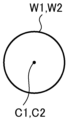
자세하게는, 워크 잔재(W2)를 회전하는 워크(W1)에 대고 누른 후(도 2의 스텝 S11), 워크(W1)를 제1 주축(10)에, 워크 잔재(W2)를 제2 주축(20)에 각각 파지한 상태에서, 제1 주축(10)만을 회전 구동하면, 제1 주축(10)의 회전은, 워크(W1), 워크 잔재(W2)를 매개로 하여 제2 주축(20)에 전달되므로, 제2 주축(20)도 따라 회전한다. 워크 잔재(W2)와 워크(W1)의 사이에 심 어긋남이 나타나면, 제2 주축(20)은, 도 4에 실선과 2점 쇄선으로 각각 나타내는 바와 같이, 제1 주축(10)의 축심(C1)에 대해서, 심 어긋남량(워크(W1)의 축심(C1)과 워크 잔재(W2)의 축심(C2)과의 거리)(s)의 2배의 진폭으로 X2축 방향으로 진동한다. Specifically, after pressing the workpiece W2 against the rotating workpiece W1 (step S11 in FIG. 2 ), the workpiece W1 is placed on the
한편, 제2 주축(20)의 X2축 방향의 위치는, X2축 모터(25c)에 의해서 유지되어 있고, X2축 모터(25c)는 제어부(40a)에 의해서 제2 주축(20)의 X2축 방향의 위치를 유지하도록 제어되고 있다(X2축 모터(25c)가 회전 구동 상태에 있음). 이 때문에, 심 어긋남에 의한 진동이 X2축 모터(25c)에 가해지면, 제어부(40a)로부터 X2축 모터(25c)에 공급되는 전류값(I2)은, 제2 주축(20)의 회전 위상에 따라서 증감한다. On the other hand, the position of the
구체적으로는, 심 어긋남량(s)의 2배의 진폭에 의한 진동이 X2축 모터(25c)에 가해진 경우, X2축 모터(25c)에 공급되는 전류값(I2)은, 도 5의 X2축 위치(세로축)와 시간(가로축)의 그래프에 실선으로 나타내는 바와 같이, 업셋 공정(U) 중에, 심 어긋남량(s)의 2배의 진폭에 상당하는 진폭으로 변동한다. Specifically, when vibration with an amplitude twice the amount of core deviation (s) is applied to the X2-
그래서, 전류값 검출 수단(40d)은 X2축 모터(25c)에 공급되는 전류값(I2)의 변동폭(최대값과 최소값과의 차)을 예를 들면 소정 기간에 걸쳐 검출한다. 그리고, 심 어긋남량 검출 수단(40c)은 이 전류값(I2)의 변동폭의 예를 들면 평균값을 구하고, 이 평균값의 반값이 심 어긋남량(s)에 상당한다고 의제(擬制)하여, 일체 접합한 워크(W1)에 대한 워크 잔재(W2)의 심 어긋남량(s)을 검출하고 있다(도 2의 스텝 S13). Therefore, the current
이와 같이, 심 어긋남량 검출 수단(40c)에 의해서, 워크(W1)와 워크 잔재(W2)의 마찰 접합 중에, 워크(W1)와 워크 잔재(W2)와의 심 어긋남의 정도를 알 수 있다. 따라서, 후술하는 바와 같이, 이 마찰 접합이 끝날 때까지 원하는 작업(예를 들면 심 어긋남의 해소)을 실시할 수 있으므로, 이 마찰 접합을 실시한 후에 접합 어긋남의 확인이나, 어긋나게 접합된 워크의 수정 등을 행할 필요가 없고, 또한, 예를 들면 디버링 작업 등을 신속하게 개시할 수 있다. 이 결과, 제품의 제조 코스트의 저감이나 품질 안정화를 실현할 수 있다. In this way, the degree of seam displacement between the workpiece W1 and the workpiece remaining material W2 can be known by the seam displacement
또한, X2축 모터(25c)에 걸리는 부하를 이용하면, 워크(W1)에 대한 워크 잔재(W2)의 심 어긋남량(s)을 용이하고 정확하게 구할 수 있다. In addition, if the load applied to the X2-
또한, 본 실시예에서는, X2축 모터(25c)에 걸리는 부하를 전류값(I2)의 변동폭의 평균값으로부터 구하는 예를 들어 설명했지만, 본 발명은 이 예로 한정되지 않는다. 예를 들면, 소정 타이밍만의 전류값(I2)의 변동폭이나, 전류값(I2)의 변동의 기준값을 설정해 두고, 이 기준값에 대한 증감량을 이용해도 된다. 또한, 전류값(I2)에 기초하는 다른 파라미터를 이용해도 된다. In this embodiment, the load applied to the X2-
한편, X2축 모터(25c)에 공급되는 전류값(I2)의 변동(최대값이나 최소값)은, 워크(W1)의 1회전 중의 거의 동일한 위치에 생기고 있다. 따라서, 전류값(I2)의 변동과 제1 주축(10)의 회전 위상(P1)을 대조하면, 워크(W1)에 대한 워크 잔재(W2)의 심 어긋남 방향도 알 수 있다. On the other hand, fluctuations (maximum value or minimum value) of the current value I2 supplied to the X2-
자세하게는, 도 5에 나타내는 바와 같이, 제1 주축(10)의 회전 위상(P1)(도면 중에 1점 쇄선으로 나타냄)과 X2축 모터(25c)에 공급되는 전류값(I2)(도면 중에 실선으로 나타냄)은, 예를 들면, 주축 모터(13)가 2회전하는 동안에 X2축 모터(25c)가 거의 1회전하는 관계에 있다. 그리고, 워크(W1)에 대한 워크 잔재(W2)의 심 어긋남 방향이, X2축의 정방향으로 생기고 있는 경우에는, X2축 모터(25c)에 공급되는 전류값(I2)이 정방향으로 증가한다. 또한, 제1 주축(10)의 회전 위상(P1)이 예를 들면 270°일 때에, X2축 모터(25c)에 공급되는 전류값(I2)이 최대값이 되고 있다. 따라서, 워크 잔재(W2)의 심 어긋남은, 제1 주축(10)의 축심(C1)과 회전 위상 270°의 위치를 연결한 방향으로 생기고 있는 것을 알 수 있다. In detail, as shown in FIG. 5, the rotational phase P1 of the first main shaft 10 (indicated by a dashed-dot line in the drawing) and the current value I2 supplied to the X2-
그래서, 도 2의 스텝 S13(도 3의 업셋 공정(U))에 있어서, 심 어긋남 방향 검출 수단(40e)은, 심 어긋남량 검출 수단(40c)에서 검출한 워크(W1)에 대한 워크 잔재(W2)의 심 어긋남량(s)과, 회전 각도 검출 수단(40f)에서 검출한 제1 주축(10)의 회전 위상(P1)을 대조하여, 워크(W1)에 대한 워크 잔재(W2)의 심 어긋남 방향을 검출하고 있다. 이와 같이, 심 어긋남 방향 검출 수단(40e)에 의해서, 워크(W1)와 워크 잔재(W2)의 마찰 접합 중에, 워크(W1)에 대한 워크 잔재(W2)의 심 어긋남 방향을 알 수 있다. Therefore, in step S13 of FIG. 2 (upset step (U) of FIG. 3), the seam displacement
다음으로, 제어부(40a)는 심 어긋남량 검출 수단(40c)에서 검출한 심 어긋남량(s)이, 심 어긋남의 수정을 필요로 하는 소정값 이상인지 여부를 판정한다(도 2의 스텝 S14). 그리고, 심 어긋남량 검출 수단(40c)에서 검출한 심 어긋남량(s)이 소정값 이상인 경우(스텝 S14의 YES), 심 어긋남을 수정하기 위해서 스텝 S15로 진행한다. 한편, 심 어긋남량 검출 수단(40c)에서 검출한 심 어긋남량(s)이 소정값 미만인 경우(스텝 S14의 NO), 스텝 S17로 진행한다. Next, the
심 어긋남의 수정을 필요로 하는 경우(스텝 S14의 YES), 제어부(40a)는, 주축 모터(13)에 구동 신호를 출력하여, 워크(W1)에 대한 워크 잔재(W2)의 심 어긋남 방향을 X2방향에 맞춘다(스텝 S15). 자세하게는, 도 6a에 나타내는 바와 같이, 워크(W1)에 대한 워크 잔재(W2)의 심 어긋남 방향(워크(W1)의 축심(C1)과 워크 잔재(W2)의 축심(C2)을 연결하는 방향)이, X2축과 평행하지 않을 때에는, 제1 주축(10)을 회전시켜, 이 심 어긋남 방향을 X2축 방향에 맞춘다. When correcting the seam misalignment is required (YES in step S14), the
다음으로, 제어부(40a)는, 예를 들면, 제1 주축(10)이 회전 정지한 직후(도 3에 시간 T3로 나타냄)에, X2축 모터(25c)에 구동 신호를 출력하여, 도 6b에 화살표로 나타내는 바와 같이, 제2 주축(20)을 X2축 방향으로서 심 어긋남량(s)이 감소하는 방향으로 이동시킨다(도 2의 스텝 S16). 보다 구체적으로는, 제2 주축(20)을, 워크 잔재(W2)의 축심(C2)으로부터 워크(W1)의 축심(C1)까지의 거리가 짧아지는 방향으로, 예를 들면 전류값(I2)의 변동폭의 평균값의 반값만큼 이동시켜 워크 잔재(W2)와 워크(W1)의 심을 맞춘다(도 6c). 이것에 의해, 워크(W1)와 워크 잔재(W2)의 마찰 접합 중에, 워크 잔재(W2)의 심 어긋남을 없앨 수 있다. Next, the
이어서, 제어부(40a)는 Z2축 모터(24c)에 구동 신호를 출력하여, 워크 잔재(W2)의 후단 부분을 워크(W1)의 선단 부분에 더 압압하여 마찰 접합을 완성한다(도 2의 스텝 S17). Next, the
또한, 제2 주축(20)을 X2축 방향으로 이동하는 타이밍(스텝 S16)은, 워크 잔재(W2)와 워크(W1)와의 접촉 개소의 온도가 높게 되어 있고, 워크 잔재(W2)가, 이 워크 잔재(W2)의 축심과 교차하는 방향으로 이동할 수 있는 상태이면 된다. 이 때문에, 상술한 시간 T3 외에, 예를 들면, 제1 주축(10)이 회전 정지하기 직전(도 3에 시간 T2로 나타냄), 또는 제1 주축(10)의 회전 속도(S1)가 점차 감소하고 있는 동안(시간 T1으로 나타냄)이어도 된다. In addition, at the timing of moving the second
그 후, 워크 잔재(W2)와 워크(W1)와의 접합 부분에 생긴 버(burr)를 공구(30)에 의해 절삭 가공한다. 이것은, 워크(W1)를 제1 주축(10)에 유지한 채로, 제2 주축(20)에 의한 워크 잔재(W2)의 유지를 해제한다. 공구(30)를, 예를 들면, 워크 잔재(W2)와 워크(W1)와의 접합 부분보다도 제2 주축(20) 근처에 배치하여, 소정의 절삭 깊이량으로 설정한다. 그리고, 제1 주축(10)을 회전시키면서 공구(30)를, 워크 잔재(W2)와 워크(W1)와의 접합 부분보다도 제1 주축(10) 근처까지 이동시켜 디버링하고 있다. After that, the
이와 같이, 대향 배치된 제1 주축(10)과 제2 주축(20)을 이용하여 워크(W1)의 선단 부분과 워크 잔재(W2)의 후단 부분을 마찰 접합하고 있어, 접합과 절삭을 융합(접합 공정과 절삭 공정을 집약)시킨 자동 선반(1)에 의해서 제품의 제조 코스트의 저감을 도모할 수 있다. In this way, the front end portion of the work W1 and the rear end portion of the work remaining W2 are friction-welded using the
또한, 상기 실시예에서는, 심 어긋남량 검출 수단(40c)이 심 어긋남량(s)을 산출하는 예를 들어 설명했다. 그러나, 본 발명은, 워크(W1)와 워크 잔재(W2)와의 접합 개소 등을 예를 들면 카메라로 촬영하여 화상 처리하는 것에 의해, 혹은, 후술하는 바와 같이 레이저를 이용하여 계측하는 것에 의해, 워크(W1)에 대한 워크 잔재(W2)의 심 어긋남량을 검출하는 경우에도 적용 가능하다. In the above embodiment, an example in which the seam displacement
또한, 상기 실시예에서는, 심 어긋남량(s)을 해소하는(없애는) 예를 들어 설명했지만, 본 발명은 심 어긋남은 해소하지는 않지만, 심 어긋남량(s)을 작게 하는 경우에도 적용된다. Further, in the above embodiment, an example of eliminating (removing) the amount s of seam misalignment has been described, but the present invention is applicable also to a case where the amount s of seam misalignment is reduced, although the seam misalignment is not eliminated.
또한, 상기 실시예에서는, 제1 주축(10)과 제2 주축(20)과의 사이에 가이드 부시(18)를 마련한 예로 설명했다. 그러나, 본 발명은 마찰 접합 중에 심 어긋남량(s)을 검출할 수 있으면 되기 때문에, 가이드 부시(18)는 생략 가능하다. 또한, 워크(W1)는 워크 잔재(W2)와는 다른 재료여도 된다. 또한, 워크(W1)와 워크 잔재(W2)는 다른 지름이어도 상관없다. 추가로, 상기 실시예에서는, 워크 잔재(W2)와 워크(W1)를 마찰 접합한 예로 설명했지만, 본 발명은 워크 잔재(W2)를 접합하는 예로 한정되는 것은 아니며, 신재끼리를 접합하는 경우에도 적용할 수 있다. In addition, in the above embodiment, an example in which the
또한, 본 발명은 적어도 제1 주축(10)이 Z1축 둘레로 회전 가능, 제2 주축(20)이 Z2축 둘레로 회전 가능하며, 제1 주축(10) 또는 제2 주축(20) 중 어느 것이 Z1축 방향 또는 Z2축 방향으로 이동 가능하고, 제1 주축(10) 또는 제2 주축(20) 중 어느 것이 X1축 방향 또는 X2축 방향으로 이동 가능하면 되며, 실시예의 구성으로 한정되지 않는다. In addition, in the present invention, at least the first
또한, 상기 실시예에서는, Z2축과 직교하는 X2축 방향으로 이동시켰지만, 본 발명은 Z2축과 교차하는 방향이면, 그 방향은 여러 가지 변경 가능하다. Further, in the above embodiment, the movement is in the direction of the X2 axis orthogonal to the Z2 axis, but in the present invention, as long as the direction intersects the Z2 axis, the direction can be changed in various ways.
실시예 2 Example 2
이어서, 도면을 참조하면서 본 발명의 제2 실시예의 공작 기계, 공작 기계의 제어 방법에 대해 설명한다. Next, the machine tool and the control method of the machine tool according to the second embodiment of the present invention will be described with reference to the drawings.
제2 실시예의 자동 선반(공작 기계)(2)은, 제1 실시예의 자동 선반(1)에 있어서의 워크(W1)에 대한 워크 잔재(W2)의 심 어긋남량(s)을 검출하는 방법을 변경한 자동 선반이다. In the automatic lathe (machine tool) 2 of the second embodiment, the method for detecting the amount s of the core deviation of the workpiece remaining W2 with respect to the workpiece W1 in the
그리고, 제2 실시예의 자동 선반(2)의 대부분의 요소도, 제1 실시예의 자동 선반(1)과 공통되므로, 공통되는 사항에 대해서는 자세한 설명을 생략한다. Since most of the elements of the
도 7에 나타내는 바와 같이, 자동 선반(2)은, 제어 장치(40)에 의해 제어되는 광학식 센서의 일종인 레이저 센서(50)를 베드(1a) 상에 가지고 있다. 이 레이저 센서(50)는, 도 8에 나타내는 바와 같이, 워크 잔재(W2)에 레이저광(L)을 X2축과 평행하게 조사하여, 레이저 센서(50)와 워크 잔재(W2)의 둘레측면과의 X2축 방향의 거리(D)를 검출한다. As shown in FIG. 7 , the
다음으로, 제2 실시예의 자동 선반(2)에 의한 워크(W1)에 대한 워크 잔재(W2)의 심 어긋남량(s)의 검출에 대해 설명한다. Next, the detection of the amount s of seam deviation of the remaining workpiece W2 with respect to the workpiece W1 by the
예를 들면, 심 어긋남량(s)의 2배의 진폭에 따른 진동이 워크 잔재(W2)에 가해진 경우, 레이저 센서(50)와 워크 잔재(W2)의 둘레측면과의 거리(D)는, 도 9의 거리(세로축)와 시간(가로축)의 그래프에 실선으로 나타내는 바와 같이, 업셋 공정(U) 중에, 레이저 센서(50)와 워크(W1)의 둘레측면과의 X2축 방향의 거리(O)를 기준으로 심 어긋남량(s)의 2배의 진폭으로 변동한다. For example, when vibration with an amplitude twice the amount of seam deviation s is applied to the work piece W2, the distance D between the
그래서, 심 어긋남량 검출 수단(40c)은, 업셋 공정(U)에, 레이저 센서(50)의 출력값(D)(레이저 센서(50)와 워크 잔재(W2)의 둘레측면과의 X2축 방향의 거리)에 기초하여, 워크(W1)의 축심(C1)에 대한 워크 잔재(W2)의 둘레측면의 X2축 방향의 변동값의 최대값, 즉, 일체 접합한 워크(W1)에 대한 워크 잔재(W2)의 심 어긋남량(s)을 검출하고 있다. Therefore, in the upset step (U), the seam displacement
다음으로, 제2 실시예의 자동 선반(2)에 의한 워크(W1)에 대한 워크 잔재(W2)의 심 어긋남 방향의 검출에 대해 설명한다. Next, the detection of the seam displacement direction of the work piece W2 with respect to the work piece W1 by the
제2 실시예에 있어서도 레이저 센서(50)의 출력값(D)의 변동(최대값이나 최소값)은, 워크(W1)의 1회전 중의 거의 동일한 위치에 생기고 있다. 따라서, 출력값(D)의 변동과 제1 주축(10)의 회전 위상(P1)을 대조하면, 워크(W1)에 대한 워크 잔재(W2)의 심 어긋남 방향도 알 수 있다. Also in the second embodiment, fluctuations (maximum value or minimum value) of the output value D of the
자세하게는, 도 9에 나타내는 바와 같이, 제1 주축(10)의 회전 위상(P1)(도면 중에 1점 쇄선으로 나타냄)과 레이저 센서(50)의 출력값(D)(도면 중에 실선으로 나타냄)은, 예를 들면, 주축 모터(13)(즉, 워크(W1))가 2회전하는 동안에 워크 잔재(W2)가 거의 1회전하는 관계에 있다. 그리고, 워크(W1)에 대한 워크 잔재(W2)의 심 어긋남 방향이, X2축의 정방향으로 생기고 있는 경우에는, 레이저 센서(50)의 출력값(D)이 정방향으로 증가한다. 또한, 제1 주축(10)의 회전 위상(P1)이 예를 들면 270°일 때에, 레이저 센서(50)의 출력값(D)이 최대값이 되고 있다. 따라서, 워크 잔재(W2)의 심 어긋남은, 제1 주축(10)의 축심(C1)과 회전 위상 270°의 위치를 연결한 방향으로 생기고 있는 것을 알 수 있다. In detail, as shown in Fig. 9, the rotational phase P1 of the first spindle 10 (indicated by a dashed-dotted line in the figure) and the output value D of the laser sensor 50 (indicated by a solid line in the figure) are , for example, while the main shaft motor 13 (namely, the workpiece W1) rotates twice, the workpiece residue W2 rotates approximately once. And, when the direction of seam deviation of the workpiece W2 with respect to the workpiece W1 occurs in the positive direction of the X2 axis, the output value D of the
그래서, 업셋 공정(U)에 있어서, 심 어긋남 방향 검출 수단(40e)은, 제1 실시예와 마찬가지로, 심 어긋남량 검출 수단(40c)에서 검출한 워크(W1)에 대한 워크 잔재(W2)의 심 어긋남량(s)과, 회전 각도 검출 수단(40f)에서 검출한 제1 주축(10)의 회전 위상(P1)을 대조하여, 워크(W1)에 대한 워크 잔재(W2)의 심 어긋남 방향을 검출하고 있다. 이와 같이, 제2 실시예의 자동 선반(2)에 있어서도, 심 어긋남 방향 검출 수단(40e)에 의해서, 워크(W1)와 워크 잔재(W2)의 마찰 접합 중에, 워크(W1)에 대한 워크 잔재(W2)의 심 어긋남 방향을 알 수 있다. Therefore, in the upset step (U), the seam displacement
이상 설명한 바와 같이, 제2 실시예에 있어서, 자동 선반(2)이 워크 잔재(W2)와의 거리를 측정하는 레이저 센서(50)를 구비하고, 심 어긋남량 검출 수단(40c)이, 레이저 센서(50)의 출력값(D)에 기초하여, 워크(W1)에 대한 워크 잔재(W2)의 심 어긋남량(s)을 구하는 것에 의해, 심 어긋남량(s)이 워크 잔재(W2)의 둘레측면의 형상으로부터 직접 검출되기 때문에, 제1 실시예와 같이 X2축 모터에 걸리는 부하에 기초하여 간접적으로 심 어긋남량(s)을 검출하는 경우에 비해, 보다 정확하게 심 어긋남량(s)을 검출할 수 있다. As described above, in the second embodiment, the
또한, 본 실시예에 있어서, 레이저 센서(50)는, 도 8에 나타내는 바와 같이, 워크 잔재(W2)에 레이저를 X2축과 평행하게 조사하여, 워크(W1)에 대한 워크 잔재(W2)의 심 어긋남량(s)과 심 어긋남 방향을 검출하고 있었지만, 심 어긋남량 검출 수단(40c)에서 심 어긋남량(s)을 산출할 수 있으면 어떠한 방향이어도 되며, 워크 잔재(W2)에 대한 레이저의 조사 방향은 X2축과 평행으로 한정되는 것은 아니다. Further, in the present embodiment, as shown in FIG. 8, the
또한, 본 실시예에 있어서, 광학식 센서의 일례로서 레이저광(L)을 이용한 레이저 센서(50)를 이용하여 설명했지만, 광학식 센서는 레이저 센서로 한정되는 것은 아니며, 측정 정밀도에 따라서 적절히 선택되면 되고, 예를 들면, LED광 등의 출사광을 이용한 광학식 센서여도 된다. In addition, in this embodiment, the
1…자동 선반(공작 기계)
1a…베드
10…제1 주축
12…주축대
13…주축 모터
14…Z1축 방향 이송 기구
14a…Z1축 레일
14b…Z1축 슬라이더
14c…Z1축 모터
17…지지대
18…가이드 부시
20…제2 주축
22…주축대
23…주축 모터
24…Z2축 방향 이송 기구
24a…Z2축 레일
24b…Z2축 슬라이더
24c…Z2축 모터
25…X2축 방향 이송 기구(제2 주축 이동 수단)
25a…X2축 레일
25b…X2축 슬라이더
25c…X2축 모터(모터)
30…공구
31…공구대
32…이동대
40…제어 장치
40a…제어부
40b…입력부
40c…심 어긋남량 검출 수단
40d…전류값 검출 수단
40e…심 어긋남 방향 검출 수단
40f…회전 각도 검출 수단
50…레이저 센서(광학식 센서)
W1…워크(제1 워크)
W2…워크 잔재(제2 워크)
M…마찰 공정
U…업셋 공정
S1…회전 속도
P1…회전 위상
I2…전류값
T1…시간
T2…시간
T3…시간
s…심 어긋남량
D…레이저 센서와 워크 잔재의 둘레측면과의 X2축 방향의 거리
L…레이저광One… Automatic lathe (machine tool) 1a… bed
10...
13...
14a... Z1-
14c... Z1-
18... guide
22...
24... Z2-axis
24b...
25... X2-axis direction transfer mechanism (2nd spindle moving means)
25a...
25c... X2 axis motor (motor) 30… tool
31...
40...
40b...
40 d... Current value detecting means 40e... Shim misalignment direction detecting means
40 f... Rotation angle detecting means 50 . . . Laser sensor (optical sensor)
W1... Work (first work) W2... Work remnants (second work)
M... Friction process U... upset process
S1... Rotational speed P1... rotational phase
I2... Current value T1... hour
T2... Time T3... hour
s… amount of seam deviation
D... Distance in the X2-axis direction between the laser sensor and the circumferential side of the work piece
L... laser light
Claims (8)
상기 제어부가, 상기 제1 워크에 대한 상기 제2 워크의 심 어긋남량을, 상기 마찰 접합하고 있는 동안에 검출하는 심 어긋남량 검출 수단을 가지는 공작 기계. A first spindle holding the first workpiece rotatably, a second spindle facing the first spindle and holding the second workpiece rotatably, and the first workpiece held on the first spindle or the first spindle While rotating at least one of the second workpieces held by the two main shafts, the first main shaft and the second main shaft are relatively moved so that they approach each other, so that the rear end portion of the second workpiece is moved to the front end portion of the first workpiece. As a machine tool having a control unit for friction welding by pressing,
The machine tool in which the control unit has a seam displacement amount detecting means for detecting an amount of seam displacement of the second workpiece with respect to the first workpiece during friction welding.
상기 심 어긋남량 검출 수단에서 검출된 상기 제1 워크에 대한 상기 제2 워크의 심 어긋남량에 기초하여, 상기 마찰 접합하고 있는 동안에, 상기 제2 주축을 상기 제2 주축의 회전 축선과 교차하는 방향으로 이동시키는 제2 주축 이동 수단을 가지는 공작 기계. The method of claim 1,
Based on the seam displacement amount of the second workpiece with respect to the first workpiece detected by the seam displacement amount detecting means, the direction crossing the second spindle with the rotational axis of the second spindle during friction welding. A machine tool having a second spindle moving means for moving to.
상기 제2 주축을 상기 제2 주축의 회전 축선과 교차하는 방향으로 이동하는 타이밍이, 상기 제1 주축이 회전 정지한 직후, 혹은 상기 제1 주축이 회전 정지하기 직전, 또는 상기 제1 주축의 회전 속도가 점차 감소하고 있는 동안인 공작 기계. The method of claim 2,
The timing of moving the second main shaft in a direction intersecting the rotational axis of the second main shaft is immediately after the first main shaft stops rotating, immediately before the first main shaft stops rotating, or the rotation of the first main shaft Machine tools while the speed is gradually decreasing.
상기 제어부가, 상기 심 어긋남량 검출 수단에서 검출한 상기 제1 워크에 대한 상기 제2 워크의 심 어긋남량과 상기 제1 주축의 회전 위상을 대조하는 것에 의해, 상기 제1 워크에 대한 상기 제2 워크의 심 어긋남 방향을, 상기 마찰 접합하고 있는 동안에 검출하는 심 어긋남 방향 검출 수단을 가지는 공작 기계. The method according to any one of claims 1 to 3,
The control unit compares the seam displacement amount of the second workpiece with respect to the first workpiece detected by the seam displacement amount detecting means and the rotational phase of the first spindle, so that the second workpiece relative to the first workpiece is detected. A machine tool having a seam displacement direction detecting means for detecting a seam displacement direction of a workpiece during said friction welding.
상기 제2 주축 이동 수단이, 상기 심 어긋남량 검출 수단에서 검출된 상기 제1 워크에 대한 상기 제2 워크의 심 어긋남량과 상기 심 어긋남 방향 검출 수단에서 검출된 상기 제1 워크에 대한 상기 제2 워크의 심 어긋남 방향에 기초하여, 상기 제2 주축을, 상기 제1 워크에 대한 상기 제2 워크의 심 어긋남량이 감소하도록 상기 제2 주축의 회전 축선과 교차하는 방향으로 이동시키는 공작 기계. The method of claim 4,
The second main axis moving means determines the amount of seam deviation of the second workpiece relative to the first workpiece detected by the seam deviation amount detecting means and the second workpiece relative to the first work detected by the seam deviation direction detection means. Based on the seam displacement direction of the workpiece, the second spindle is moved in a direction crossing the rotational axis of the second spindle so as to reduce the amount of seam displacement of the second workpiece relative to the first workpiece.
상기 심 어긋남량 검출 수단이, 상기 제2 주축의 회전 축선과 교차하는 방향으로 상기 제2 주축을 이동시키는 모터에 걸리는 부하에 기초하여, 상기 제1 워크에 대한 상기 제2 워크의 심 어긋남량을 구하는 공작 기계. The method according to any one of claims 1 to 5,
The seam displacement amount detecting means calculates the seam displacement amount of the second workpiece with respect to the first workpiece based on a load applied to a motor that moves the second spindle in a direction intersecting the rotational axis of the second spindle. machine tools to obtain.
상기 심 어긋남량 검출 수단이, 상기 제2 워크와의 거리를 측정하는 광학식 센서의 출력값에 기초하여, 상기 제1 워크에 대한 상기 제2 워크의 심 어긋남량을 구하는 공작 기계. The method according to any one of claims 1 to 5,
The machine tool according to claim 1 , wherein the seam displacement amount detecting means obtains an amount of seam displacement of the second workpiece with respect to the first workpiece based on an output value of an optical sensor that measures a distance to the second workpiece.
상기 제1 주축에 유지된 상기 제1 워크 또는 상기 제2 주축에 유지된 상기 제2 워크 중 적어도 어느 일방을 회전시키면서, 상기 제1 주축과 상기 제2 주축이 서로 접근하도록 상대적으로 이동시켜, 상기 제2 워크의 후단 부분을 새롭게 공급된 제1 워크의 선단 부분에 접촉하여 마찰시키는 스텝과,
상기 제2 워크의 후단 부분을 상기 제1 워크의 선단 부분에 압압하여 마찰 접합하고 있는 동안에, 상기 제1 워크에 대한 상기 제2 워크의 심 어긋남량을 검출하는 스텝과,
상기 마찰 접합하고 있는 동안에, 상기 제1 워크에 대한 상기 제2 워크의 심 어긋남 방향을 검출하는 스텝과,
상기 마찰 접합하고 있는 동안에, 검출한 상기 제1 워크에 대한 상기 제2 워크의 심 어긋남량 및 검출한 상기 제1 워크에 대한 상기 제2 워크의 심 어긋남 방향에 기초하여, 상기 제2 주축을, 상기 제1 워크에 대한 상기 제2 워크의 심 어긋남량이 감소하도록 상기 제2 주축의 회전 축선과 교차하는 방향으로 이동시키는 스텝을 포함하는 공작 기계의 제어 방법. A first main shaft that rotatably holds the first workpiece, a second main shaft that is disposed opposite to the first main shaft and rotatably holds a second workpiece transferred from the first main shaft, the first main shaft, and the As a control method of a machine tool having a control unit for controlling the operation of a second spindle,
While rotating at least one of the first work held on the first main shaft and the second work held on the second main shaft, the first main shaft and the second main shaft are relatively moved so as to approach each other, A step of contacting and rubbing the rear end of the second work with the front end of the newly supplied first work;
A step of detecting an amount of seam displacement of the second workpiece with respect to the first workpiece while the rear end portion of the second workpiece is pressurized and friction-bonded to the front end portion of the first workpiece;
detecting a seam displacement direction of the second workpiece with respect to the first workpiece during friction welding;
During the friction welding, based on the detected amount of seam displacement of the second workpiece with respect to the first workpiece and the detected direction of seam displacement of the second workpiece with respect to the first workpiece, the second main shaft, and moving the second workpiece in a direction crossing the axis of rotation of the second workpiece so as to reduce the amount of seam displacement of the second workpiece with respect to the first workpiece.
Applications Claiming Priority (3)
| Application Number | Priority Date | Filing Date | Title |
|---|---|---|---|
| JP2020112424 | 2020-06-30 | ||
| JPJP-P-2020-112424 | 2020-06-30 | ||
| PCT/JP2021/024277 WO2022004625A1 (en) | 2020-06-30 | 2021-06-28 | Machine tool and method for controlling machine tool |
Publications (1)
| Publication Number | Publication Date |
|---|---|
| KR20230028251A true KR20230028251A (en) | 2023-02-28 |
Family
ID=79315356
Family Applications (1)
| Application Number | Title | Priority Date | Filing Date |
|---|---|---|---|
| KR1020227041591A KR20230028251A (en) | 2020-06-30 | 2021-06-28 | Machine tools, machine tool control methods |
Country Status (7)
| Country | Link |
|---|---|
| US (1) | US20230182230A1 (en) |
| EP (1) | EP4129538A4 (en) |
| JP (1) | JPWO2022004625A1 (en) |
| KR (1) | KR20230028251A (en) |
| CN (1) | CN115702398A (en) |
| TW (1) | TW202204074A (en) |
| WO (1) | WO2022004625A1 (en) |
Families Citing this family (1)
| Publication number | Priority date | Publication date | Assignee | Title |
|---|---|---|---|---|
| CN117161674B (en) * | 2023-11-02 | 2024-02-09 | 兴化市广福金属制品有限公司 | Metal product butt welding device |
Citations (2)
| Publication number | Priority date | Publication date | Assignee | Title |
|---|---|---|---|---|
| JPH05208281A (en) | 1992-01-31 | 1993-08-20 | Nippon Steel Corp | Detection of abnormality at the time of friction-press-joining steel pipe |
| JPH07195183A (en) | 1994-01-05 | 1995-08-01 | Hitachi Ltd | Method and device for deciding normal/defective condition of friction welding product |
Family Cites Families (9)
| Publication number | Priority date | Publication date | Assignee | Title |
|---|---|---|---|---|
| GB1264863A (en) * | 1969-03-18 | 1972-02-23 | ||
| JP2501702B2 (en) * | 1992-01-08 | 1996-05-29 | 千代田化工建設株式会社 | Friction welding machine |
| JPH09285876A (en) * | 1996-04-23 | 1997-11-04 | Daido Steel Co Ltd | Method for aligning materials to be joined in diffusion welding |
| JP3433621B2 (en) * | 1996-10-18 | 2003-08-04 | トヨタ自動車株式会社 | Friction welding method |
| JP3984723B2 (en) * | 1998-09-07 | 2007-10-03 | 株式会社豊田自動織機 | Clamp device and friction welding device |
| DE102004001274A1 (en) * | 2004-01-08 | 2005-08-04 | Mtu Aero Engines Gmbh | rotary friction |
| JP6155155B2 (en) * | 2013-09-27 | 2017-06-28 | 三菱重工業株式会社 | Friction stir tool, friction stir welding apparatus, and friction stir welding method |
| KR102533754B1 (en) * | 2017-11-27 | 2023-05-17 | 시티즌 도케이 가부시키가이샤 | Friction welding method and machine tool |
| JP7195160B2 (en) * | 2019-01-18 | 2022-12-23 | シチズン時計株式会社 | Machine Tools |
-
2021
- 2021-06-28 TW TW110123935A patent/TW202204074A/en unknown
- 2021-06-28 JP JP2022533972A patent/JPWO2022004625A1/ja active Pending
- 2021-06-28 CN CN202180043055.9A patent/CN115702398A/en active Pending
- 2021-06-28 WO PCT/JP2021/024277 patent/WO2022004625A1/en unknown
- 2021-06-28 EP EP21833512.3A patent/EP4129538A4/en active Pending
- 2021-06-28 US US17/923,643 patent/US20230182230A1/en active Pending
- 2021-06-28 KR KR1020227041591A patent/KR20230028251A/en unknown
Patent Citations (2)
| Publication number | Priority date | Publication date | Assignee | Title |
|---|---|---|---|---|
| JPH05208281A (en) | 1992-01-31 | 1993-08-20 | Nippon Steel Corp | Detection of abnormality at the time of friction-press-joining steel pipe |
| JPH07195183A (en) | 1994-01-05 | 1995-08-01 | Hitachi Ltd | Method and device for deciding normal/defective condition of friction welding product |
Also Published As
| Publication number | Publication date |
|---|---|
| TW202204074A (en) | 2022-02-01 |
| JPWO2022004625A1 (en) | 2022-01-06 |
| EP4129538A4 (en) | 2024-04-17 |
| WO2022004625A1 (en) | 2022-01-06 |
| EP4129538A1 (en) | 2023-02-08 |
| CN115702398A (en) | 2023-02-14 |
| US20230182230A1 (en) | 2023-06-15 |
Similar Documents
| Publication | Publication Date | Title |
|---|---|---|
| US11338386B2 (en) | Friction welding method and machine tool | |
| US11465230B2 (en) | Machine tool | |
| KR20230028251A (en) | Machine tools, machine tool control methods | |
| TWI809242B (en) | working machinery | |
| JP7312762B2 (en) | Machine Tools | |
| TWI803707B (en) | working machinery | |
| KR102632289B1 (en) | Machine tools and processing methods | |
| WO2021193344A1 (en) | Machine tool and method for controlling machine tool | |
| JP5668241B2 (en) | Work cutting confirmation device, work cutting system and work cutting confirmation method | |
| JP2018187738A (en) | Machine tool | |
| JPS5964182A (en) | Upset welding method |