JP6155155B2 - Friction stir tool, friction stir welding apparatus, and friction stir welding method - Google Patents
Friction stir tool, friction stir welding apparatus, and friction stir welding method Download PDFInfo
- Publication number
- JP6155155B2 JP6155155B2 JP2013202758A JP2013202758A JP6155155B2 JP 6155155 B2 JP6155155 B2 JP 6155155B2 JP 2013202758 A JP2013202758 A JP 2013202758A JP 2013202758 A JP2013202758 A JP 2013202758A JP 6155155 B2 JP6155155 B2 JP 6155155B2
- Authority
- JP
- Japan
- Prior art keywords
- tool
- friction stir
- rotating
- protrusion
- probe
- Prior art date
- Legal status (The legal status is an assumption and is not a legal conclusion. Google has not performed a legal analysis and makes no representation as to the accuracy of the status listed.)
- Expired - Fee Related
Links
- 238000003756 stirring Methods 0.000 title claims description 180
- 238000003466 welding Methods 0.000 title claims description 98
- 238000000034 method Methods 0.000 title claims description 19
- 230000007246 mechanism Effects 0.000 claims description 148
- 239000000523 sample Substances 0.000 claims description 126
- 238000003780 insertion Methods 0.000 claims description 81
- 230000037431 insertion Effects 0.000 claims description 81
- 238000005304 joining Methods 0.000 claims description 40
- 238000003825 pressing Methods 0.000 claims description 18
- 239000007769 metal material Substances 0.000 claims description 11
- 238000001514 detection method Methods 0.000 claims description 7
- 239000000463 material Substances 0.000 claims description 7
- 229910052751 metal Inorganic materials 0.000 description 55
- 239000002184 metal Substances 0.000 description 55
- 238000010586 diagram Methods 0.000 description 13
- 230000002093 peripheral effect Effects 0.000 description 13
- 230000007547 defect Effects 0.000 description 10
- 230000008859 change Effects 0.000 description 7
- 230000004048 modification Effects 0.000 description 6
- 238000012986 modification Methods 0.000 description 6
- 230000008569 process Effects 0.000 description 6
- 238000003860 storage Methods 0.000 description 6
- 230000001360 synchronised effect Effects 0.000 description 5
- 230000004308 accommodation Effects 0.000 description 4
- 238000001125 extrusion Methods 0.000 description 4
- 238000005452 bending Methods 0.000 description 3
- 230000003247 decreasing effect Effects 0.000 description 3
- 229910000838 Al alloy Inorganic materials 0.000 description 2
- 238000013019 agitation Methods 0.000 description 2
- 230000007423 decrease Effects 0.000 description 2
- 230000035515 penetration Effects 0.000 description 2
- 230000015572 biosynthetic process Effects 0.000 description 1
- 239000000470 constituent Substances 0.000 description 1
- 238000006073 displacement reaction Methods 0.000 description 1
- 238000005259 measurement Methods 0.000 description 1
- 238000012545 processing Methods 0.000 description 1
- 239000000758 substrate Substances 0.000 description 1
Images


Classifications
-
- B—PERFORMING OPERATIONS; TRANSPORTING
- B23—MACHINE TOOLS; METAL-WORKING NOT OTHERWISE PROVIDED FOR
- B23K—SOLDERING OR UNSOLDERING; WELDING; CLADDING OR PLATING BY SOLDERING OR WELDING; CUTTING BY APPLYING HEAT LOCALLY, e.g. FLAME CUTTING; WORKING BY LASER BEAM
- B23K20/00—Non-electric welding by applying impact or other pressure, with or without the application of heat, e.g. cladding or plating
- B23K20/12—Non-electric welding by applying impact or other pressure, with or without the application of heat, e.g. cladding or plating the heat being generated by friction; Friction welding
- B23K20/122—Non-electric welding by applying impact or other pressure, with or without the application of heat, e.g. cladding or plating the heat being generated by friction; Friction welding using a non-consumable tool, e.g. friction stir welding
- B23K20/1245—Non-electric welding by applying impact or other pressure, with or without the application of heat, e.g. cladding or plating the heat being generated by friction; Friction welding using a non-consumable tool, e.g. friction stir welding characterised by the apparatus
- B23K20/1255—Tools therefor, e.g. characterised by the shape of the probe
-
- B—PERFORMING OPERATIONS; TRANSPORTING
- B23—MACHINE TOOLS; METAL-WORKING NOT OTHERWISE PROVIDED FOR
- B23K—SOLDERING OR UNSOLDERING; WELDING; CLADDING OR PLATING BY SOLDERING OR WELDING; CUTTING BY APPLYING HEAT LOCALLY, e.g. FLAME CUTTING; WORKING BY LASER BEAM
- B23K20/00—Non-electric welding by applying impact or other pressure, with or without the application of heat, e.g. cladding or plating
- B23K20/12—Non-electric welding by applying impact or other pressure, with or without the application of heat, e.g. cladding or plating the heat being generated by friction; Friction welding
- B23K20/122—Non-electric welding by applying impact or other pressure, with or without the application of heat, e.g. cladding or plating the heat being generated by friction; Friction welding using a non-consumable tool, e.g. friction stir welding
- B23K20/123—Controlling or monitoring the welding process
-
- B—PERFORMING OPERATIONS; TRANSPORTING
- B23—MACHINE TOOLS; METAL-WORKING NOT OTHERWISE PROVIDED FOR
- B23K—SOLDERING OR UNSOLDERING; WELDING; CLADDING OR PLATING BY SOLDERING OR WELDING; CUTTING BY APPLYING HEAT LOCALLY, e.g. FLAME CUTTING; WORKING BY LASER BEAM
- B23K20/00—Non-electric welding by applying impact or other pressure, with or without the application of heat, e.g. cladding or plating
- B23K20/12—Non-electric welding by applying impact or other pressure, with or without the application of heat, e.g. cladding or plating the heat being generated by friction; Friction welding
- B23K20/122—Non-electric welding by applying impact or other pressure, with or without the application of heat, e.g. cladding or plating the heat being generated by friction; Friction welding using a non-consumable tool, e.g. friction stir welding
- B23K20/1245—Non-electric welding by applying impact or other pressure, with or without the application of heat, e.g. cladding or plating the heat being generated by friction; Friction welding using a non-consumable tool, e.g. friction stir welding characterised by the apparatus
- B23K20/125—Rotary tool drive mechanism
Description
本発明は、摩擦撹拌接合に用いられる摩擦撹拌工具、摩擦撹拌接合装置及び摩擦撹拌接合方法に関するものである。 The present invention relates to a friction stir tool used for friction stir welding, a friction stir welding apparatus, and a friction stir welding method.
従来、金属板の接合部にその表面側及び裏面側から挿入される上下の回転ツールを用い、上下の回転ツールにより摩擦撹拌して金属板を接合する摩擦撹拌接合装置が知られている(例えば、特許文献1参照)。この摩擦撹拌接合装置において、上下の回転ツールは、円筒形のツール本体と、ツール本体の先端部に取り付けられたプローブとを有している。そして、ツール本体の先端部におけるプローブの取り付け部の周辺にショルダ部が形成されている。摩擦撹拌接合装置は、上下の回転ツールのプローブの先端間に所定の隙間を与えた状態で摩擦撹拌接合を行っている。 2. Description of the Related Art Conventionally, a friction stir welding apparatus is known that uses upper and lower rotating tools inserted from the front surface side and the back surface side of a joining portion of a metal plate and frictionally stirs the upper and lower rotating tools to join the metal plates (for example, , See Patent Document 1). In this friction stir welding apparatus, the upper and lower rotary tools have a cylindrical tool body and a probe attached to the tip of the tool body. A shoulder portion is formed around the probe attachment portion at the tip of the tool body. The friction stir welding apparatus performs friction stir welding in a state where a predetermined gap is provided between the tips of the probes of the upper and lower rotary tools.
また、金属板の接合部の表面側及び裏面側に相対向するように配置される第1及び第2の回転ツールを用い、第1及び第2の回転ツールにより摩擦撹拌して金属板を接合する摩擦撹拌接合装置が知られている(例えば、特許文献2参照)。この摩擦撹拌接合装置において、第1及び第2の回転ツールの一方は、ショルダ部を先端部分に形成したツール本体と、ツール本体から突出して形成されたプローブ(突起部)とを有し、他方は、ショルダ部を先端部分に形成したツール本体と、プローブの先端部を収納する凹み部とを有している。摩擦撹拌接合装置は、一方の回転ツールの突起部を、他方の回転ツールの凹み部に挿入した状態で摩擦撹拌接合を行っている。 Also, the first and second rotary tools arranged so as to face the front side and the back side of the joint portion of the metal plate are used, and the metal plates are joined by friction stirring with the first and second rotary tools. A friction stir welding apparatus is known (see, for example, Patent Document 2). In this friction stir welding apparatus, one of the first and second rotary tools has a tool body in which a shoulder portion is formed at a tip portion, and a probe (projection) formed to protrude from the tool body, Has a tool body in which a shoulder portion is formed at the tip portion, and a recess portion that houses the tip portion of the probe. The friction stir welding apparatus performs the friction stir welding in a state where the protrusion of one rotary tool is inserted into the recess of the other rotary tool.
しかしながら、特許文献1に記載の摩擦撹拌接合装置は、上下の回転ツールのプローブの先端間に所定の隙間が与えられる。このため、金属板の板厚が厚くなると、材料規格で許容される公差の絶対値が大きくなるため、隙間が大きくなってしまい、キッシングボンドと呼ばれる接合欠陥部(未接合部)が発生する可能性がある。特に、2000系や7000系のアルミニウム合金のような接合温度での流動特性が悪い材料では、許容できる隙間の量が小さく、このような欠陥が発生しやすい。さらに、接合後の金属板を塑性加工する場合には、接合欠陥部を起因とする亀裂等の破損が発生する可能性がある。However, in the friction stir welding apparatus described in Patent Document 1, a predetermined gap is provided between the tips of the probes of the upper and lower rotary tools. For this reason, as the thickness of the metal plate increases, the absolute value of the tolerance allowed by the material standard increases, so that the gap increases and a bonding defect (unbonded portion) called a kissing bond may occur. There is sex. In particular, the flow properties poor material at the bonding temperature, such as 2000 series or 7000 series of Aluminum alloy, small amounts of allowable clearance, such defects are likely to occur. Further, when plastic processing is performed on the metal plate after joining, there is a possibility that breakage such as a crack caused by a joint defect portion may occur.
また、特許文献2に記載の摩擦撹拌接合装置は、プローブが金属板の厚さ方向に亘って設けられている。このため、金属板の板厚が厚くなると、プローブの長さを長くする必要がある。プローブの長さを長くすると、プローブに加わる曲げモーメントが大きくなるため、工具への負荷が大きくなってしまい、工具の破損につながる可能性も高い。また、工具に加わる負荷に耐え得る構成とすると、プローブの径を大きくする必要があるため、回転ツールを大きなものとしなければならず、これに伴って、工具を駆動する軸やモータ等の装置構成を大きくすることになってしまう。 In the friction stir welding apparatus described in Patent Document 2, the probe is provided over the thickness direction of the metal plate. For this reason, when the plate | board thickness of a metal plate becomes thick, it is necessary to lengthen the length of a probe. When the length of the probe is increased, the bending moment applied to the probe increases, so that the load on the tool increases and the tool is likely to be damaged. In addition, if it is configured to withstand the load applied to the tool, it is necessary to increase the diameter of the probe, so the rotary tool must be made large, and in accordance with this, devices such as shafts and motors that drive the tool The configuration will be enlarged.
そこで、本発明は、金属材の接合部における厚さが変化しても、工具に加わる負荷を抑制しつつ、接合部の摩擦撹拌接合を好適に行うことができる摩擦撹拌工具、摩擦撹拌接合装置及び摩擦撹拌接合方法を提供することを課題とする。 Therefore, the present invention provides a friction stir tool and a friction stir welding apparatus that can suitably perform friction stir welding of a joint while suppressing a load applied to the tool even when the thickness of the joint of the metal material changes. It is another object of the present invention to provide a friction stir welding method.
本発明の摩擦撹拌工具は、部材の被接合部に対し、前記被接合部を挟んで一方側に配置される第1回転ツールと、前記被接合部を挟んで他方側に配置され、前記第1回転ツールに対向して設けられる第2回転ツールと、を備え、前記第1回転ツールは、前記被接合部の一方側の面と接する第1ショルダ部を有する第1ツール本体と、前記第1ツール本体から前記第2回転ツールに向かって突出する第1プローブと、前記第1プローブから前記第2回転ツールに向かって突出する突起部と、を有し、前記第2回転ツールは、前記被接合部の他方側の面と接する第2ショルダ部を有する第2ツール本体と、前記第2ツール本体から前記第1回転ツールに向かって突出する第2プローブと、前記第2プローブに設けられ、前記第1回転ツールの前記突起部を収容可能な突起収容部と、を有することを特徴とする。 Friction stir tool of the present invention, with respect to the junction member, said a first rotating tool disposed therebetween at one side of the joined portion is arranged on the other side across the bonding portion, the second A second rotating tool provided opposite to the one-rotating tool, wherein the first rotating tool has a first tool body having a first shoulder portion in contact with one surface of the joined portion; A first probe protruding from the tool main body toward the second rotating tool, and a protrusion protruding from the first probe toward the second rotating tool, and the second rotating tool includes: A second tool body having a second shoulder portion in contact with the other surface of the joined portion; a second probe protruding from the second tool body toward the first rotating tool; and the second probe. , The first rotating tool It characterized by having a a projection receiving portion capable of accommodating the raised portion.
また、前記部材は、金属材であることが好ましい。 The member is preferably a metal material.
この構成によれば、第1回転ツールの突起部を、第2回転ツールの突起収容部に収容させ、第1回転ツール及び第2回転ツールを回転させて、金属材(部材)の被接合部の両側から入熱を行いながら、被接合部を摩擦撹拌接合することができる。このため、金属材の被接合部の厚みが厚くなっても、突起収容部に対する突起部の収容深さ(挿入深さ)を適宜変更することで、第1プローブ、第2プローブ及び突起部により、被接合部の厚みに亘って摩擦撹拌することができる。これにより、第1プローブと第2プローブとの間に所定の隙間が形成されることがないため、接合欠陥部の発生を抑制することができる。また、金属材の被接合部の厚みが厚くなっても、突起収容部に対する突起部の収容深さを変更すればよいため、第1プローブ及び第2プローブの突出方向における長さを変える必要がないことから、工具への負荷の増大を抑制することができる。以上から、金属材の被接合部における厚さが変化しても、工具に加わる負荷を抑制しつつ、被接合部の摩擦撹拌接合を好適に行うことができる。なお、第1回転ツール及び第2回転ツールは、その回転方向及び回転速度が任意となっている。 According to this configuration, the protrusion of the first rotating tool is accommodated in the protrusion accommodating portion of the second rotating tool, and the first rotating tool and the second rotating tool are rotated to join the metal material (member) to be joined. The parts to be joined can be friction stir welded while heat is input from both sides. For this reason, even if the thickness of the bonded portion of the metal material is increased, the first probe, the second probe, and the protruding portion can be changed by appropriately changing the depth (insertion depth) of the protruding portion with respect to the protruding portion. In addition, friction stirring can be performed over the thickness of the bonded portion. Thereby, since a predetermined gap is not formed between the first probe and the second probe, it is possible to suppress the occurrence of a bonding defect portion. In addition, even if the thickness of the bonded portion of the metal material is increased, it is only necessary to change the accommodation depth of the projection with respect to the projection accommodation portion, and thus it is necessary to change the length in the projecting direction of the first probe and the second probe. Therefore, an increase in load on the tool can be suppressed. From the above, even if the thickness of the welded portion of the metal material changes, the friction stir welding of the welded portion can be suitably performed while suppressing the load applied to the tool. Note that the rotation direction and the rotation speed of the first rotation tool and the second rotation tool are arbitrary.
また、前記突起部の突出方向における長さは、前記第1プローブ及び前記突起部を合わせた突出方向における長さに比して、50%以下となっていることが好ましい。 Moreover, it is preferable that the length in the protruding direction of the protruding portion is 50% or less as compared with the length in the protruding direction in which the first probe and the protruding portion are combined.
この構成によれば、突起部の長さを、第1プローブの長さよりも短くすることができるため、突起部に加わる曲げモーメントを小さくできることから、突起部への負荷を抑制することができる。 According to this configuration, since the length of the protrusion can be made shorter than the length of the first probe, the bending moment applied to the protrusion can be reduced, so that the load on the protrusion can be suppressed.
また、前記突起部の回転直径は、前記第2プローブの前記第1回転ツール側の回転直径に対し、40%から80%までの間の直径となっていることが好ましい。 In addition, it is preferable that the rotation diameter of the protrusion is between 40% and 80% of the rotation diameter of the second probe on the first rotation tool side.
この構成によれば、第2プローブに突起収容部を設けることで、第2プローブの第1プローブ側に形成される突起収容部の周囲の壁体の厚さを、第2プローブの回転直径の10%から30%の厚さとすることができる。例えば、突起部の回転直径が第2プローブの第1回転ツール側の回転直径に対して80%である場合、突起部が収容される突起収容部の周囲の壁体の厚さを、第2プローブの回転直径の10%の厚さとすることができる。また、例えば、突起部の回転直径が第2プローブの第1回転ツール側の回転直径に対して40%である場合、突起部が収容される突起収容部の周囲の壁体の厚さを、第2プローブの回転直径の30%の厚さとすることができる。このため、第2プローブの第1プローブ側に形成される突起収容部の周囲の壁体の厚さを確保することができる。これにより、突起部が突起収容部の内面に接触した場合であっても、第2プローブの第1プローブ側に形成される突起収容部の周囲の壁体の剛性を、突起部と突起収容部の内面との接触に耐え得る剛性にすることができる。 According to this configuration, by providing the protrusion accommodating portion on the second probe, the thickness of the wall body around the protrusion accommodating portion formed on the first probe side of the second probe is set to the rotational diameter of the second probe. The thickness can be 10% to 30%. For example, when the rotation diameter of the protrusion is 80% with respect to the rotation diameter of the second probe on the first rotating tool side, the thickness of the wall around the protrusion accommodating portion where the protrusion is accommodated is set to the second The thickness can be 10% of the rotational diameter of the probe. Further, for example, when the rotation diameter of the protrusion is 40% with respect to the rotation diameter of the second probe on the first rotating tool side, the thickness of the wall body around the protrusion accommodating part in which the protrusion is accommodated, The thickness can be 30% of the rotational diameter of the second probe. For this reason, it is possible to ensure the thickness of the wall body around the protrusion accommodating portion formed on the first probe side of the second probe. Thus, even when the protrusion is in contact with the inner surface of the protrusion accommodating portion, the rigidity of the wall body around the protrusion accommodating portion formed on the first probe side of the second probe can be reduced. The rigidity can withstand contact with the inner surface of the substrate.
また、前記突起部と、前記突起部が収容される前記突起収容部の内面との間には、非接触状態となる所定の隙間が設けられていることが好ましい。 Moreover, it is preferable that the predetermined clearance gap which becomes a non-contact state is provided between the said projection part and the inner surface of the said projection accommodating part in which the said projection part is accommodated.
この構成によれば、突起部と突起収容部の内面とを非接触状態とすることができるため、接触による第1回転ツール及び第2回転ツールへの負荷を低減することができる。 According to this configuration, since the protrusion and the inner surface of the protrusion accommodating portion can be brought into a non-contact state, it is possible to reduce a load on the first rotating tool and the second rotating tool due to contact.
また、前記突起収容部は、前記第2回転ツールの回転軸に直交する面で切った断面が円形となっていることが好ましい。 Moreover, it is preferable that the said protrusion accommodating part is circular in the cross section cut by the surface orthogonal to the rotating shaft of a said 2nd rotation tool.
この構成によれば、突起収容部の断面を円形にすることで、突起収容部を回転させた場合であっても、突起収容部の形状が変わらないことから、突起部の形状に対して柔軟に対応することができ、これにより、第1回転ツールと第2回転ツールの回転に差が生じた場合でも、突起部との接触を生じ難くすることができる。 According to this configuration, since the shape of the protrusion accommodating portion does not change even when the protrusion accommodating portion is rotated by making the cross section of the protrusion accommodating portion circular, the shape of the protrusion accommodating portion is flexible. Thus, even when there is a difference in rotation between the first rotary tool and the second rotary tool, it is possible to make it difficult to make contact with the protrusion.
また、前記突起部は、前記第1回転ツールの回転軸に直交する面で切った断面が多角形となっていることが好ましい。 Moreover, it is preferable that the cross section cut by the surface orthogonal to the rotating shaft of the said 1st rotation tool is a polygon in the said projection part.
この構成によれば、突起部の断面を多角形にすることで、摩擦により軟化する被接合部を、突起部により好適に撹拌することができる。 According to this structure, the to-be-joined part softened by friction can be suitably stirred by a projection part by making the cross section of a projection part polygonal.
また、前記被接合部の厚さが、予め想定される最大厚さである場合、前記第1回転ツール及び前記第2回転ツールは、前記被接合部の溶接時において、前記突起収容部に前記突起部の少なくとも一部を収容した状態で回転させられることが好ましい。 Further, when the thickness of the bonded portion is a maximum thickness assumed in advance, the first rotating tool and the second rotating tool are placed in the protrusion accommodating portion during welding of the bonded portion. It is preferable that the projection is rotated in a state where at least a part of the projection is accommodated.
この構成によれば、被接合部が想定される最大厚さであっても、突起収容部に突起部を収容した状態で、第1回転ツール及び第2回転ツールを回転させることができるため、2つの回転ツール間に隙間ができることがない。 According to this configuration, the first rotating tool and the second rotating tool can be rotated in a state where the protrusion is accommodated in the protrusion accommodating portion even if the bonded portion has the maximum thickness. There is no gap between the two rotating tools.
また、前記被接合部の一方側の面に直交する方向と前記第1回転ツールの回転軸とがなす角度、及び前記被接合部の他方側の面に直交する方向と前記第2回転ツールの回転軸とがなす角度は、0°から3°の間の角度であることが好ましい。 In addition, an angle formed between a direction orthogonal to one surface of the bonded portion and the rotation axis of the first rotating tool, and a direction orthogonal to the other surface of the bonded portion and the second rotating tool The angle formed by the rotation axis is preferably an angle between 0 ° and 3 °.
この構成によれば、上記の角度が0°である場合には、被接合部の一方側の面に対し、第1回転ツールの回転軸を直交させることができ、同様に、被接合部の他方側の面に対し、第2回転ツールの回転軸を直交させることができる。このため、被接合部の両面に対して第1ショルダ部及び第2ショルダ部を平行に接触させることができることから、各ショルダ部による被接合部への入熱を効率良く行うことができる。また、上記の角度が0°よりも大きい場合には、接合部の両面に対して第1回転ツールの回転軸及び第2回転ツールの回転軸を傾けることができるため、各ショルダ部のショルダ面が被接合部の表面(接触面)に対して傾斜を持った形で当たることになり、被接合部を積極的に撹拌することができる。 According to this configuration, when the angle is 0 °, the rotation axis of the first rotary tool can be orthogonal to the surface on one side of the joined portion. The rotation axis of the second rotary tool can be orthogonal to the surface on the other side. For this reason, since a 1st shoulder part and a 2nd shoulder part can be made to contact in parallel with both surfaces of a joined part, heat input to a joined part by each shoulder part can be performed efficiently. Further, when the above angle is larger than 0 °, the rotation axis of the first rotation tool and the rotation axis of the second rotation tool can be inclined with respect to both surfaces of the joint portion. Will hit the surface (contact surface) of the bonded portion with an inclination, and the bonded portion can be actively stirred.
また、前記突起部は、前記第1プローブに対し、着脱自在に固定されることが好ましい。 Moreover, it is preferable that the protrusion is detachably fixed to the first probe.
この構成によれば、突起部を交換することが可能となるため、突起部が損傷した場合には、新たな突起部に取り替えることができる。また、被接合部の厚みに応じて、適切な長さとなる突起部を選定して装着することが可能となる。 According to this configuration, since the protrusion can be replaced, if the protrusion is damaged, it can be replaced with a new protrusion. In addition, it is possible to select and attach a protrusion having an appropriate length according to the thickness of the bonded portion.
また、前記第1プローブは、前記突起部を固定する固定穴をさらに有し、前記突起部は、前記固定穴の外側に突出し、前記第1プローブに接触するフランジ部を有することが好ましい。 The first probe may further include a fixing hole for fixing the protruding portion, and the protruding portion may have a flange portion that protrudes outside the fixing hole and contacts the first probe.
この構成によれば、固定穴に突起部を固定した状態において、摩擦により軟化した被接合部の金属が、固定穴と突起部との隙間へ侵入することを、フランジ部によって抑制することができる。これにより、固定穴と突起部とが金属により固着することを抑制することができる。 According to this configuration, in a state where the protrusion is fixed to the fixing hole, the flange portion can prevent the metal of the bonded portion softened by friction from entering the gap between the fixing hole and the protrusion. . Thereby, it can suppress that a fixing hole and a projection part adhere by a metal.
また、前記突起部は、前記第2プローブよりも硬度の低い材料を用いて構成されることが好ましい。 Moreover, it is preferable that the protrusion is configured using a material having a hardness lower than that of the second probe.
この構成によれば、第2プローブの突起収容部に突起部が接触した場合、交換可能な突起部によって、第2プローブへの接触による衝撃を吸収することができる。 According to this structure, when a projection part contacts the projection accommodating part of a 2nd probe, the impact by the contact to a 2nd probe can be absorbed by the exchangeable projection part.
また、前記突起部は、前記被接合部の厚さに応じて突出方向の長さが異なるものが複数種用意されていることが好ましい。 Further, it is preferable that a plurality of types of protrusions having different lengths in the protruding direction depending on the thickness of the bonded portion are prepared.
この構成によれば、被接合部の厚さに適した突出方向の長さとなる突起部を選定して、第1プローブの固定穴に取り付けることができる。このため、被接合部の厚さに適した突起部を用いることで、摩擦撹拌接合を好適に行うことができる。 According to this configuration, it is possible to select a protrusion having a length in the protruding direction suitable for the thickness of the bonded portion and attach it to the fixing hole of the first probe. For this reason, friction stir welding can be performed suitably by using the projection part suitable for the thickness of a to-be-joined part.
また、前記第1回転ツールは、前記第1回転ツールの回転軸に沿って、前記第1プローブに貫通形成される第1挿通穴と、前記第1挿通穴の内部を移動可能な突起ピンと、を有し、前記突起部は、前記第1挿通穴から突出する前記突起ピンの一部であることが好ましい。 Further, the first rotary tool includes a first insertion hole formed through the first probe along a rotation axis of the first rotation tool, and a projection pin movable within the first insertion hole, It is preferable that the protruding portion is a part of the protruding pin protruding from the first insertion hole.
この構成によれば、突起ピンを第1挿通穴の内部で移動させて、突起収容部に突起ピンを収容させることができる。このため、接合部の厚さが変わった場合、第1挿通穴に対する突起ピンの突出量を変更するだけで、接合部の厚さに適した突起部の長さに簡単に変更することができる。なお、突起ピンの回転は、第1回転ツールまたは第2回転ツールの回転速度及び回転方向に従ってもよいし、独立していてもよく、特に限定されない。 According to this configuration, the protrusion pin can be accommodated in the protrusion accommodating portion by moving the protrusion pin inside the first insertion hole. For this reason, when the thickness of the joining portion changes, it is possible to easily change the length of the projecting portion suitable for the thickness of the joining portion simply by changing the protruding amount of the projecting pin with respect to the first insertion hole. . Note that the rotation of the projecting pins may be in accordance with the rotational speed and direction of the first rotating tool or the second rotating tool, or may be independent, and is not particularly limited.
また、前記突起収容部は、前記第2回転ツールの回転軸に沿って、前記第2プローブに貫通形成され、前記突起ピンの一部が挿入される第2挿通穴であることが好ましい。 In addition, it is preferable that the protrusion accommodating portion is a second insertion hole that is formed through the second probe along the rotation axis of the second rotary tool and into which a part of the protrusion pin is inserted.
この構成によれば、突起ピンを第2挿通穴に挿入することができるため、突起ピンの第2挿通穴に対する挿入深さを適切な深さにすることができる。この場合、突起ピンは、第1挿通穴と第2挿通穴とに挿入されることから、第1回転ツールの回転軸と第2回転ツールの回転軸とは同軸となるため、被接合部に対して第1回転ツール及び第2回転ツールを傾けずに摩擦撹拌接合が行われる。また、第2挿通穴に対する突起ピンの挿入深さが深ければ、第1回転ツールの回転軸と第2回転ツールの回転軸との芯合わせを精度良く行うことができる。一方で、第2挿通穴に対する突起ピンの挿入深さが浅ければ、突起ピンが僅かに傾いた場合であっても、第2挿通穴の内部で突起ピンの傾きを許容できるため、突起ピンへの負荷を抑制することができる。 According to this configuration, since the projection pin can be inserted into the second insertion hole, the insertion depth of the projection pin with respect to the second insertion hole can be set to an appropriate depth. In this case, since the projecting pin is inserted into the first insertion hole and the second insertion hole, the rotation axis of the first rotation tool and the rotation axis of the second rotation tool are coaxial, so that On the other hand, friction stir welding is performed without tilting the first rotating tool and the second rotating tool. Moreover, if the insertion depth of the projection pin with respect to the second insertion hole is deep, the centering of the rotation axis of the first rotation tool and the rotation axis of the second rotation tool can be accurately performed. On the other hand, if the insertion depth of the projection pin with respect to the second insertion hole is shallow, even if the projection pin is slightly inclined, the inclination of the projection pin can be allowed inside the second insertion hole. The load on can be suppressed.
また、前記第2回転ツールは、前記第2挿通穴の内部を移動可能な押出しピンを、さらに有することが好ましい。 Moreover, it is preferable that the said 2nd rotation tool further has the extrusion pin which can move the inside of the said 2nd insertion hole.
この構成によれば、溶接後において、摩擦により軟化した被接合部の一部が第2挿通穴に侵入する場合であっても、押出しピンにより、第2挿通穴に侵入した被接合部の軟化した金属を接合完了とともに押し出して、第2挿通穴の外部に排出することができる。このため、第2挿通穴の内部において、侵入した被接合部が固着することを抑制することができる。 According to this configuration, after welding, even if a part of the welded part softened by friction enters the second insertion hole, the pusher pin softens the joined part that has entered the second insertion hole. The extruded metal can be pushed out together with the completion of joining and discharged to the outside of the second insertion hole. For this reason, it can suppress that the to-be-joined joined part adheres inside the 2nd penetration hole.
また、前記突起ピンと前記第1挿通穴とは、スプラインで結合されていることが好ましい。 The projecting pin and the first insertion hole are preferably connected by a spline.
この構成によれば、第1挿通穴に対する突起ピンの移動を許容する一方で、突起ピンの回転を第1回転ツールの回転と同期させることができる。 According to this configuration, it is possible to synchronize the rotation of the projection pin with the rotation of the first rotation tool while allowing the projection pin to move with respect to the first insertion hole.
また、前記突起ピンは、前記第1挿通穴に対して回転自在に挿通されていることが好ましい。 Moreover, it is preferable that the protruding pin is rotatably inserted into the first insertion hole.
この構成によれば、第1回転ツールに同期させることなく、突起ピンを独立して回転させることができる。このため、各ショルダ部の入熱と突起部による撹拌とを独立に制御することができるため、突起ピンの回転を金属材の被接合部のすべての領域において摩擦撹拌接合に適した回転にすることができる。 According to this configuration, the projecting pins can be rotated independently without being synchronized with the first rotating tool. For this reason, since heat input of each shoulder part and agitation by the projection part can be controlled independently, the rotation of the projection pin is set to a rotation suitable for friction agitation welding in all regions of the joined part of the metal material. be able to.
また、前記突起ピンと前記第1挿通穴との隙間は、前記突起ピンの前記第2回転ツール側となる先端側が狭く、前記突起ピンの後端側が広いことが好ましい。 Moreover, it is preferable that the clearance gap between the said projection pin and the said 1st insertion hole is narrow at the front end side which becomes the said 2nd rotation tool side of the said projection pin, and the rear end side of the said projection pin is wide.
この構成によれば、突起ピンの先端側において、第1挿通穴との隙間が狭くなっているため、突起ピンの先端側における位置決めを精度良く行うことが可能となる。一方で、突起ピンの後端側において、第1挿通穴との隙間が広くなっているため、突起ピンの変形を許容することができ、突起ピンへの負荷を抑制することができる。 According to this configuration, since the gap with the first insertion hole is narrow on the distal end side of the projecting pin, positioning on the distal end side of the projecting pin can be performed with high accuracy. On the other hand, since the gap with the first insertion hole is wide on the rear end side of the projecting pin, deformation of the projecting pin can be allowed and the load on the projecting pin can be suppressed.
また、前記被接合部は、一対の板状の前記部材を突き合わせることで形成される開先部であることが好ましい。 Moreover, it is preferable that the said to-be-joined part is a groove part formed by abutting a pair of said plate-shaped member .
この構成によれば、突き合わせた一対の板状の部材を摩擦撹拌接合することができる。 According to this configuration, the pair of plate-shaped members that are butted together can be friction stir welded.
本発明の摩擦撹拌接合装置は、上記の摩擦撹拌工具と、前記摩擦撹拌工具の前記第1回転ツールの前記第1ショルダ部を前記被接合部の一方側の面に押し当てた状態で、前記第1回転ツールを回転させる第1押圧回転機構と、前記摩擦撹拌工具の前記第2回転ツールの前記第2ショルダ部を前記被接合部の他方側の面に押し当てた状態で、前記第2回転ツールを回転させる第2押圧回転機構と、前記部材に対し、前記第1回転ツールを前記部材の前記被接合部に沿って移動させる第1移動機構と、前記部材に対し、前記第2回転ツールを前記部材の前記被接合部に沿って移動させる第2移動機構と、前記第1押圧回転機構、前記第2押圧回転機構、前記第1移動機構及び前記第2移動機構を制御する制御部と、を備える。 In the friction stir welding apparatus according to the present invention, the friction stir tool described above and the first shoulder portion of the first rotary tool of the friction stir tool pressed against one surface of the joined portion, In a state where the first pressing and rotating mechanism for rotating the first rotating tool and the second shoulder portion of the second rotating tool of the friction stir tool are pressed against the other surface of the joined portion, the second a second press rotating mechanism for rotating the rotating tool relative to said member, a first moving mechanism for moving said first rotary tool along the bonding portion of the member relative to said member, said second rotary A second moving mechanism for moving the tool along the joined portion of the member , and a controller for controlling the first pressing and rotating mechanism, the second pressing and rotating mechanism, the first moving mechanism, and the second moving mechanism. And comprising.
この構成によれば、上記の摩擦撹拌工具を用いることで、部材の被接合部における厚さが変化しても、工具に加わる負荷を抑制しつつ、被接合部の摩擦撹拌接合を好適に行うことができる。 According to this configuration, by using the friction stir tool described above, the friction stir welding of the welded portion is suitably performed while suppressing the load applied to the tool even if the thickness of the welded portion of the member changes. be able to.
また、前記第1移動機構及び前記第2移動機構は、前記部材の前記被接合部に沿って前記第1回転ツール及び前記第2回転ツールを同期して移動させることが好ましい。 Further, it is preferable that the first moving mechanism and the second moving mechanism move the first rotating tool and the second rotating tool synchronously along the joined portion of the member .
この構成によれば、第1回転ツール及び第2回転ツールの移動を同期させることができるため、移動によって第1回転ツールと第2回転ツールとが位置ずれすることを抑制することができ、摩擦撹拌工具の突起部と突起収納部との接触を抑制することができる。 According to this configuration, since the movements of the first rotating tool and the second rotating tool can be synchronized, it is possible to suppress the displacement of the first rotating tool and the second rotating tool due to the movement, and friction. Contact between the protrusion of the stirring tool and the protrusion storage portion can be suppressed.
また、前記摩擦撹拌工具の負荷を検出する工具負荷検出器を、さらに備え、前記制御部は、前記工具負荷検出器の検出結果に基づいて、前記摩擦撹拌工具の負荷が小さくなるように、前記第1押圧回転機構、前記第2押圧回転機構、前記第1移動機構及び前記第2移動機構の少なくとも1つを制御することが好ましい。 Further, a tool load detector for detecting a load of the friction stir tool is further provided, and the control unit is configured to reduce the load of the friction stir tool based on a detection result of the tool load detector. It is preferable to control at least one of the first pressing and rotating mechanism, the second pressing and rotating mechanism, the first moving mechanism, and the second moving mechanism.
この構成によれば、制御部は、摩擦撹拌工具に負荷が加わる場合、摩擦撹拌工具の負荷が小さくなるように、前記第1押圧回転機構、前記第2押圧回転機構、第1移動機構及び第2移動機構の少なくとも一方を制御することで、摩擦撹拌工具への負荷を抑制することができ、摩擦撹拌工具の突起部と突起収納部との接触を抑制することができる。 According to this configuration, when the load is applied to the friction stir tool, the control unit reduces the load on the friction stir tool so that the first press rotation mechanism, the second press rotation mechanism, the first movement mechanism, and the first By controlling at least one of the two moving mechanisms, it is possible to suppress a load on the friction stir tool, and to suppress contact between the protrusion of the friction stir tool and the protrusion storage portion.
また、前記工具負荷検出器は、前記第1移動機構の動力源に加わる負荷を検出する第1動力負荷検出器と、前記第2移動機構の動力源に加わる負荷を検出する第2動力負荷検出器と、を有し、前記制御部は、前記第1動力負荷検出器により検出された負荷と、前記第2動力負荷検出器により検出された負荷との差分が小さくなるように、前記第1移動機構及び前記第2移動機構の少なくとも一方を制御することが好ましい。 The tool load detector includes a first power load detector that detects a load applied to the power source of the first movement mechanism, and a second power load detection that detects a load applied to the power source of the second movement mechanism. And the control unit reduces the difference between the load detected by the first power load detector and the load detected by the second power load detector. It is preferable to control at least one of the moving mechanism and the second moving mechanism.
この構成によれば、制御部は、第1移動機構及び第2移動機構の動力源に加わる負荷の差分が小さくなるように、第1移動機構及び第2移動機構の少なくとも一方を制御することで、摩擦撹拌工具への負荷を抑制することができ、摩擦撹拌工具の突起部と突起収納部との接触を抑制することができる。 According to this configuration, the control unit controls at least one of the first movement mechanism and the second movement mechanism so that the difference in load applied to the power source of the first movement mechanism and the second movement mechanism becomes small. The load on the friction stir tool can be suppressed, and the contact between the protrusion of the friction stir tool and the protrusion storage portion can be suppressed.
また、前記工具負荷検出器は、前記第1回転ツール及び前記第2回転ツールの少なくとも一方の回転軸の歪みを検出する歪み検出器を有し、前記制御部は、前記歪み検出器により検出された歪みが小さくなるように、前記第1移動機構及び前記第2移動機構の少なくとも一方を制御することが好ましい。 Further, the tool load detector includes a strain detector that detects strain of at least one of the first rotating tool and the second rotating tool, and the control unit is detected by the strain detector. It is preferable to control at least one of the first moving mechanism and the second moving mechanism so as to reduce the distortion.
この構成によれば、制御部は、第1回転ツール及び第2回転ツールの少なくとも一方の回転軸の歪みが小さくなるように、第1移動機構及び第2移動機構の少なくとも一方を制御することで、摩擦撹拌工具への負荷を抑制することができ、摩擦撹拌工具の突起部と突起収納部との接触を抑制することができる。 According to this configuration, the control unit controls at least one of the first movement mechanism and the second movement mechanism so that the distortion of the rotation axis of at least one of the first rotation tool and the second rotation tool is reduced. The load on the friction stir tool can be suppressed, and the contact between the protrusion of the friction stir tool and the protrusion storage portion can be suppressed.
また、前記工具負荷検出器は、前記摩擦撹拌工具の作動音を検出する作動音検出器を有し、前記制御部は、前記作動音検出器により検出された作動音が小さくなるように、前記第1移動機構及び前記第2移動機構の少なくとも一方を制御することが好ましい。 Further, the tool load detector includes an operation sound detector that detects an operation sound of the friction stir tool, and the control unit is configured to reduce the operation sound detected by the operation sound detector. It is preferable to control at least one of the first moving mechanism and the second moving mechanism.
この構成によれば、制御部は、摩擦撹拌工具の作動音が小さくなるように、第1移動機構及び第2移動機構の少なくとも一方を制御することで、摩擦撹拌工具への負荷を抑制することができ、摩擦撹拌工具の突起部と突起収納部との接触を抑制することができる。 According to this configuration, the control unit controls the load on the friction stir tool by controlling at least one of the first moving mechanism and the second moving mechanism so that the operation noise of the friction stir tool is reduced. And the contact between the protrusion of the friction stir tool and the protrusion storage portion can be suppressed.
また、前記工具負荷検出器は、前記第1回転ツール及び前記第2回転ツールの少なくとも一方の振動を検出する振動検出器を有し、前記制御部は、前記振動検出器により検出された振動モードが、前記第1回転ツール及び前記第2回転ツールの少なくとも一方に負荷が加わったときの負荷振動モードである場合、前記負荷振動モード以外の振動モードとなるように、前記第1移動機構及び前記第2移動機構の少なくとも一方を制御することが好ましい。 The tool load detector includes a vibration detector that detects vibration of at least one of the first rotating tool and the second rotating tool, and the control unit is configured to detect a vibration mode detected by the vibration detector. Is a load vibration mode when a load is applied to at least one of the first rotation tool and the second rotation tool, the first moving mechanism and the first movement mechanism so as to be in a vibration mode other than the load vibration mode. It is preferable to control at least one of the second moving mechanisms.
この構成によれば、制御部は、負荷振動モード以外の振動モードとなるように、第1移動機構及び第2移動機構の少なくとも一方を制御することで、摩擦撹拌工具への負荷を抑制することができ、摩擦撹拌工具の突起部と突起収納部との接触を抑制することができる。 According to this configuration, the control unit controls the load on the friction stir tool by controlling at least one of the first moving mechanism and the second moving mechanism so as to be in a vibration mode other than the load vibration mode. And the contact between the protrusion of the friction stir tool and the protrusion storage portion can be suppressed.
本発明の摩擦撹拌接合方法は、上記の摩擦撹拌工具を用いて、前記部材の前記被接合部を溶接する摩擦撹拌接合方法であって、接合開始点に予め貫通形成された貫通穴に対し、前記貫通穴の一方側から前記第1回転ツールを挿入し、前記貫通穴の他方側から前記第2回転ツールを挿入すると共に、前記第1回転ツールの前記突起部を、前記第2回転ツールの前記突起収容部に収容させ、前記第1回転ツールと前記第2回転ツールとを回転させる回転工程と、前記第1回転ツールと前記第2回転ツールとの差し込み位置を相対的に調整する位置調整工程と、前記第1回転ツール及び前記第2回転ツールを前記部材の前記被接合部に沿って前記接合開始点から接合終了点まで移動させる移動工程と、前記接合終了点において、前記第1回転ツール及び前記第2回転ツールを回転させた状態で、前記第1回転ツール及び前記第2回転ツールを前記被接合部から引き抜く引抜工程と、を備えることを特徴とする。 The friction stir welding method of the present invention is a friction stir welding method for welding the joined parts of the members using the friction stir tool described above, with respect to a through-hole formed in advance at a joining start point, The first rotary tool is inserted from one side of the through hole, the second rotary tool is inserted from the other side of the through hole, and the protrusion of the first rotary tool is inserted into the second rotary tool. Rotation step of rotating the first rotating tool and the second rotating tool by being housed in the protrusion accommodating portion, and position adjustment for relatively adjusting the insertion position of the first rotating tool and the second rotating tool A step of moving the first rotating tool and the second rotating tool from the joining start point to the joining end point along the joined portion of the member ; and the first rotation tool at the joining end point. tool While rotating the fine second rotating tool, characterized in that it comprises a drawing step of withdrawing the first rotary tool and said second rotary tool from said bonding portion.
この構成によれば、上記の摩擦撹拌工具を用いることで、部材の被接合部における厚さが変化しても、工具に加わる負荷を抑制しつつ、接合開始点から接合終了点まで被接合部の摩擦撹拌接合を好適に行うことができる。 According to this configuration, by using the friction stir tool described above, even if the thickness of the member to be joined changes, the load to be applied to the tool is suppressed and the joined portion from the joining start point to the joining end point is suppressed. The friction stir welding can be suitably performed.
また、前記移動工程では、前記第1回転ツールと前記第2回転ツールとの位置を相対的に調整していることが好ましい。 In the moving step, it is preferable that the positions of the first rotating tool and the second rotating tool are relatively adjusted.
この構成によれば、位置調整工程だけでなく、移動工程でも、第1回転ツールと第2回転ツールとの相対的な位置を調整することができるため、第1回転ツールと第2回転ツールとの接触を抑制することができ、摩擦撹拌工具に加わる負荷を抑制することができる。 According to this configuration, since the relative positions of the first rotating tool and the second rotating tool can be adjusted not only in the position adjusting process but also in the moving process, the first rotating tool and the second rotating tool The load applied to the friction stir tool can be suppressed.
また、前記貫通穴は、一方側の前記第1回転ツールと前記貫通穴との隙間と、他方側の前記第2回転ツールと前記貫通穴との隙間とが異なるような内径となっていることが好ましい。 The through hole has an inner diameter such that a gap between the first rotary tool and the through hole on one side is different from a gap between the second rotary tool and the through hole on the other side. Is preferred.
この構成によれば、隙間の広い側の回転ツールを先に挿入して回転ツールのショルダ部のショルダ面で穴をふさいだ後、反対側の回転ツールで穴の側壁を削り、それを反対側の回転ツールと貫通穴との隙間に充てんすることで、接合開始部の貫通穴の隙間を減らすことができ、貫通穴への金属材の充填率を高めることができるため、接合開始部の欠陥やへこみの発生を抑制できる。 According to this configuration, after inserting the rotary tool on the wide gap side first and closing the hole with the shoulder surface of the shoulder part of the rotary tool, scrape the side wall of the hole with the rotary tool on the opposite side, and place it on the opposite side By filling the gap between the rotary tool and the through hole, the gap of the through hole at the joining start part can be reduced, and the filling rate of the metal material into the through hole can be increased, so the defect at the joining start part Generation of dents can be suppressed.
また、前記接合開始点及び前記接合終了点の少なくとも一方は、前記部材に取り付けられたタブ板上となっていることが好ましい。 Moreover, it is preferable that at least one of the joining start point and the joining end point is on a tab plate attached to the member .
この構成によれば、接合開始点に形成される貫通穴、及び接合終了点において第1回転ツール及び第2回転ツールを引き抜くことにより形成される穴が、部材上に形成されることなく、タブ板上に形成することができる。 According to this configuration, the through hole formed at the joining start point and the hole formed by pulling out the first rotating tool and the second rotating tool at the joining end point are formed on the member without being formed on the member. It can be formed on a plate.
以下に、本発明に係る実施例を図面に基づいて詳細に説明する。なお、この実施例によりこの発明が限定されるものではない。また、下記実施例における構成要素には、当業者が置換可能かつ容易なもの、あるいは実質的に同一のものが含まれる。 Embodiments according to the present invention will be described below in detail with reference to the drawings. Note that the present invention is not limited to the embodiments. In addition, constituent elements in the following embodiments include those that can be easily replaced by those skilled in the art or those that are substantially the same.
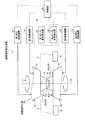
図1は、実施例1に係る摩擦撹拌接合装置を模式的に表した概略構成図である。図2は、実施例1に係る摩擦撹拌工具に関する説明図である。図3から図5は、第1ショルダ部の形状の一例を示す平面図である。図6は、突起部及び突起収容部の形状の一例を示す平面図である。図7は、摩擦撹拌接合前の金属板の一例を示す説明図である。図8は、実施例1に係る摩擦撹拌接合方法のフローチャートである。 FIG. 1 is a schematic configuration diagram schematically illustrating the friction stir welding apparatus according to the first embodiment. FIG. 2 is an explanatory diagram relating to the friction stir tool according to the first embodiment. 3 to 5 are plan views showing an example of the shape of the first shoulder portion. FIG. 6 is a plan view showing an example of the shape of the protrusion and the protrusion accommodating part. FIG. 7 is an explanatory view showing an example of a metal plate before friction stir welding. FIG. 8 is a flowchart of the friction stir welding method according to the first embodiment.
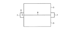
実施例1の摩擦撹拌接合装置1は、一対の金属板5を突き合わせることで形成される開先部6を、開先部6の表裏に配置される一対の回転ツール21,22を用いて摩擦撹拌することにより、一対の金属板5を接合する、いわゆる摩擦撹拌接合(FSW:Friction Stir Welding)を行う装置である。先ず、図1及び図7を参照し、接合対象となる一対の金属板5について説明する。なお、実施例1では、接合対象となる部材として一対の金属板5を例示したが、部材は、金属材以外を用いたものであってもよく、特に限定されない。
The friction stir welding apparatus 1 according to the first embodiment uses a pair of
金属板5は、例えば、アルミニウム合金を用いて構成されており、一辺が2m以上となる大型の長方形状の板材となっている。また、金属板5は、その厚みが15mm以上となっている。図1に示すように、一対の金属板5は、端面を突き合わせることで、I形の開先部6が形成される。このため、開先部6は、図7に示すように、所定の方向に直線状に延びて形成される。また、この一対の金属板5には、直線状に延びる開先部6の両側に、タブ板7がそれぞれ取り付けられている。開先部6の両側の一対のタブ板7は、一対の金属板5に仮溶接等により取り付けられることで、一対の金属板5の相互の位置を固定する。このとき、摩擦撹拌接合における接合開始点は、一方のタブ板7上となっており、接合終了点は、他方のタブ板7上となっている。このため、摩擦撹拌接合は、一方のタブ板7から開先部6を通って他方のタブ板7へ向かって行われる。なお、詳細は後述するが、一方のタブ板7上の接合開始点には、あらかじめ一対の回転ツール21,22が挿入される貫通穴8が貫通形成されている。
The
なお、実施例1の摩擦撹拌接合装置1は、一対の金属板5を突き合わせた開先部6に対して、摩擦撹拌接合を行うが、この構成に限定されず、例えば、重ね合わせた複数の金属板5に対して、摩擦撹拌接合を行ってもよい。
In addition, although the friction stir welding apparatus 1 of Example 1 performs friction stir welding with respect to the groove | channel part 6 which faced | matched a pair of
ここで、摩擦撹拌接合により接合された一対の金属板5は、大型の金属板として取り扱われ、後工程において、塑性加工が行われる。このため、摩擦撹拌接合により接合された一対の金属板5の被接合部(開先部6)に、接合欠陥部(キッシングボンド)が形成されると、接合欠陥部を起因とする亀裂、割れ等の破損が生じる可能性があることから、実施例1の摩擦撹拌装置1では、接合欠陥部の形成を抑制すべく、下記する構成となっている。
Here, the pair of
図1を参照して、摩擦撹拌接合装置1について説明する。図1に示す摩擦撹拌接合装置1は、開先部6の厚み方向の両側から摩擦撹拌接合を行っている。摩擦撹拌接合装置1は、摩擦撹拌工具10と、第1押圧回転機構11と、第2押圧回転機構12と、第1移動機構13と、第2移動機構14と、支持治具15と、工具負荷検出器16と、制御部20とを備えている。この摩擦撹拌接合装置1は、一対の金属板5の位置を固定した状態で、摩擦撹拌工具10を開先部6に沿って移動させながら、摩擦撹拌接合を行っている。
The friction stir welding apparatus 1 will be described with reference to FIG. The friction stir welding apparatus 1 shown in FIG. 1 performs friction stir welding from both sides of the groove portion 6 in the thickness direction. The friction stir welding apparatus 1 includes a
摩擦撹拌工具10は、第1回転ツール21と第2回転ツール22とを有している。第1回転ツール21は、開先部6を挟んで、厚さ方向の一方側(表面側:図1の上側)に配置されている。第1回転ツール21は、第1回転軸I1を中心に回転すると共に、開先部6の表面に押圧される。第2回転ツール22は、開先部6を挟んで、厚さ方向の他方側(裏面側:図1の下側)に配置されている。第2回転ツール22は、第2回転軸I2を中心に回転すると共に、開先部6の裏面に押圧される。そして、第1回転ツール21と第2回転ツール22とは、厚さ方向において対向するように配置され、第1回転ツール21及び第2回転ツール22の回転方向は、相互に逆方向となっている。また、第1回転ツール21の第1回転軸I1と第2回転ツール22の第2回転軸I2とは、同軸となっている。このため、第1回転軸I1及び第2回転軸I2は、開先部6の表面及び裏面に対して、直交している。
The
なお、実施例1では、第1回転ツール21及び第2回転ツール22の回転方向が、相互に逆方向となるようにしたが、この構成に限定されない。第1回転ツール21及び第2回転ツール22は、摩擦撹拌接合に適していれば、いずれの回転方向であってもよく、また、いずれの回転速度であってもよい。
In the first embodiment, the rotation directions of the
第1回転ツール21は、第1ツール本体31と、第1プローブ32と、突起部33と、を有している。第1ツール本体31は、第2回転ツール22側となる先端側に、第1ショルダ部35が形成されている。第1ショルダ部35は、その先端側の面が、開先部6の一方側(表面側:図1の上側)の表面と接する円形の第1ショルダ面35aとなっている。第1回転ツール21は、第1ショルダ部35の第1ショルダ面35aを開先部6の表面に接触させた状態で回転することで、開先部6に対して摩擦による熱を与え、熱を与えることで軟化した開先部6の金属を撹拌する。第1プローブ32の長さは、一般的には開先部6の最小板厚の半分よりもわずかに短い。
The first
ここで、第1ショルダ部35は、図3から図5に示す形状となっており、実施例1では、いずれの形状であってもよい。第1ショルダ部35は、第1ショルダ面35aから第1ツール本体31側に溝形状の凹部36が形成されている。この凹部36は、第1ショルダ部35と金属板5とを擦ることで軟化した金属が、第1ショルダ部35の中心側へ向かうような形状となっている。
Here, the
具体的に、図3に示す凹部36は、1本で構成されており、1本の凹部36は、第1ショルダ面35aにおいて、外側から内側に向かう渦巻状(スクロール形状)に配置されている。図4に示す凹部36は、2本で構成されており、2本の凹部36は、第1ショルダ面35aにおいて、180°位相が異なる位置に設けられ、外側から内側に向かう渦巻状に配置されている。図5に示す凹部36は、複数本で構成されており、複数本の凹部36は、第1ショルダ面35aの周方向に所定の間隔を空けて設けられると共に、外側から内側に向かって直線状に配置されている。
Specifically, the
再び、図1を参照して、第1プローブ32は、第1ツール本体31の第1ショルダ面35aから先端側に突出して設けられている。第1プローブ32は、軟化した開先部6の内部に没する配置となり、第1ツール本体31と一体となって回転するように、第1ツール本体31に固定されている。この第1プローブ32は、後端側の直径が太く、また、先端側に向かうにつれて直径が細くなるテーパ形状に形成されている。第1プローブ32は、その先端側の面が、円形の先端面32aとなっている。また、第1プローブ32の外周面には、軟化した開先部6の金属を撹拌するための溝が形成されている。
Referring again to FIG. 1, the
突起部33は、第1プローブ32の先端面32aから先端側に突出して設けられている。突出部33は、第1プローブ32と同様に、軟化した開先部6の内部に没する配置となり、第1ツール本体31及び第1プローブ32と一体となって回転するように、第1プローブ32と一体となっている。ここで、突起部33は、第1回転軸I1に直交する面で切った断面が多角形となっている。突起部33は、例えば、図6に示すように、断面が正六角形となっている。なお、実施例1では、突起部33の断面を正六角形としたが、正三角形または正方形であってもよい。
The
また、図2に示すように、突起部33は、突出方向における長さ、つまり、第1回転軸I1の軸方向における長さlが、第1プローブ32及び突起部33を合わせた軸方向における長さLに比して、50%以下となっている。つまり、突起部33の軸方向における長さlは、第1プローブ32の軸方向における長さ以下となっている。
As shown in FIG. 2, the
再び、図1を参照して、第2回転ツール22は、第2ツール本体41と、第2プローブ42と、突起収容部43と、を有している。第2ツール本体41は、第1回転ツール21側となる先端側に、第2ショルダ部45が形成されている。第2ショルダ部45は、第1ショルダ部35と同様に構成されており、その先端側の面が、開先部6の他方側(裏面側:図1の下側)の裏面と接する円形の第2ショルダ面45aとなっている。第2回転ツール22は、第2ショルダ部45の第2ショルダ面45aを開先部6の裏面に接触させた状態で回転することで、開先部6に対して摩擦による熱を与え、熱を与えることで軟化した開先部6の金属を撹拌する。第2プローブ42の長さは、一般的には開先部6の最小板厚の半分よりもわずかに短い。
Referring again to FIG. 1, the
ここで、第2ショルダ部45は、第1ショルダ部35と同様の凹部36が設けられている。なお、凹部36については、第1ショルダ部35と同様であるため、説明を省略する。
Here, the
第2プローブ42は、第2ツール本体41の第2ショルダ面45aから先端側に突出して設けられている。第2プローブ42は、第1プローブ32と同様に、軟化した開先部6の内部に没する配置となり、第2ツール本体41と一体となって回転するように、第2ツール本体41に固定されている。この第2プローブ42も、後端側の直径が太く、また、先端側に向かうにつれて直径が細くなるテーパ形状に形成されている。第2プローブ42は、その先端側の面が、円環状の先端面42aとなっている(図6参照)。また、第2プローブ42の外周面には、軟化した開先部6の金属を撹拌するための溝が形成されている。
The
突起収容部43は、第2プローブ42の先端面42aから後端側に没入して設けられている。突起収容部43は、例えば、図6に示すように、第2回転軸I2に直交する面で切った断面が円形となっており、第2回転軸I2を中心軸とする中空円柱形状に形成されている。突起収容部43は、第1回転ツール21の突起部33が、第2回転軸I2の軸方向に挿入されることで、突起部33の一部を収容可能となっている。つまり、突起収容部43の内径は、突起部33の回転直径よりも大きな径となっている。
The
ここで、図2に示すように、突起部33の回転直径rは、第2プローブ42の円環状の先端面42aの外側の直径(回転直径)Rに対し、40%から80%までの間の回転直径となっている。これにより、円環状の先端面42aにおける内側の直径から外側の直径までの径方向の長さは、直径Rの10%から30%の長さとすることができる。つまり、例えば、突起部33の回転直径rが第2プローブ42の回転直径Rに対し、80%の回転直径である場合、環状の先端面42aにおける内側の直径から外側の直径までの径方向の長さは、回転直径Rの10%の長さとなる。また、例えば、突起部33の回転直径rが第2プローブ42の回転直径Rに対し、40%の回転直径である場合、環状の先端面42aにおける内側の直径から外側の直径までの径方向の長さは、回転直径Rの30%の長さとなる。よって、第2プローブ42の外周面と突起収容部43の内周面との間の厚さを、突起部33の接触による負荷に耐え得る厚さとして確保することができる。
Here, as shown in FIG. 2, the rotation diameter r of the
また、図6に示すように、突起部33及び突起収容部43は、突起部33と、突起部33が収容される突起収容部43の内周面との間に所定の隙間が設けられるように形成されており、所定の隙間を設けることで、突起部33と突起収容部43とを非接触状態としている。
Further, as shown in FIG. 6, the
ところで、突起部33及び突起収容部43は、予め想定される開先部6の最大厚さに応じて設計される。つまり、開先部6の厚さが最大厚さである場合、第1回転ツール21及び第2回転ツール22は、開先部6の溶接時において、突起収容部43に突起部33の少なくとも先端部を収容した状態となるように設計される。
By the way, the
再び、図1を参照して、第1押圧回転機構11及び第2押圧回転機構12について説明する。第1押圧回転機構11は、第1回転ツール21に連結されており、制御部20によって制御されている。第1押圧回転機構11は、第1回転ツール21を開先部6へ向けて移動させると共に、第1回転ツール21を回転させる。このため、第1押圧回転機構11は、第1回転ツール21の第1ショルダ部35の第1ショルダ面35aを、開先部6の表面に押し当てた状態で、第1回転ツール21を回転させる。
Again, the 1st
第2押圧回転機構12は、第1押圧回転機構11と同様に構成され、第2回転ツール22に連結されており、制御部20によって制御されている。第2押圧回転機構12は、第2回転ツール22を開先部6へ向けて移動させると共に、第2回転ツール22を回転させる。このため、第2押圧回転機構12は、第2回転ツール22の第2ショルダ部45の第2ショルダ面45aを、開先部6の裏面に押し当てた状態で、第2回転ツール22を回転させる。
The second pressing and
第1移動機構13は、第1回転ツール21に連結されており、制御部20によって制御されている。第1移動機構13は、図示しない第1モータを動力源として、第1回転ツール21を、所定の方向に直線状に延びる開先部6に沿って移動させている。なお、この第1モータは、後述する工具負荷検出器16に接続されている。
The first moving
第2移動機構14は、第1移動機構13と同様に構成され、第2回転ツール22に連結されており、制御部20によって制御されている。第2移動機構14は、図示しない第2モータを動力源として、第2回転ツール22を、所定の方向に直線状に延びる開先部6に沿って移動させている。なお、この第2モータも、後述する工具負荷検出器16に接続されている。
The
この第1移動機構13及び第2移動機構14は、第1回転ツール21及び第2回転ツール22を同期させながら移動させている。
The first moving
支持治具15は、一対の金属板5をそれぞれ支持する一対の治具であり、開先部6を挟んで、一対の金属板5の裏面にそれぞれ設けられている。一対の支持治具15は、その上部に一対の金属板5が載置されることで、一対の金属板5をそれぞれ支持する。
The support jigs 15 are a pair of jigs that respectively support the pair of
工具負荷検出器16は、第1移動機構13の第1モータに加わる負荷を検出する第1モータ負荷検出器51と、第2移動機構14の第2モータに加わる負荷を検出する第2モータ負荷検出器52と、を有している。第1モータ負荷検出器51は、制御部20に接続され、制御部20へ向けて、第1モータに加わる負荷を出力する。第2モータ負荷検出器52は、制御部20に接続され、制御部20へ向けて、第2モータに加わる負荷を出力する。
The
制御部20は、第1押圧回転機構11、第2押圧回転機構12、第1移動機構13及び第2移動機構14が接続され、各機構11,12,13,14をそれぞれ制御する。また、制御部20は、第1モータ負荷検出器51及び第2モータ負荷検出器52が接続され、各検出器51,52の検出結果に基づいて、各機構11,12,13,14をそれぞれ制御する。
The
具体的に、制御部20は、第1押圧回転機構11及び第2押圧回転機構12を制御して、第1回転ツール21と第2回転ツール22との間に挟まれる開先部6に対する荷重が所定の荷重となるように、第1回転ツール21及び第2回転ツール22を開先部6へ向けて移動させる。また、制御部20は、第1押圧回転機構11及び第2押圧回転機構12を制御して、第1回転ツール21及び第2回転ツール22の回転方向が相互に逆方向となるように、また、所定の回転速度となるように、第1回転ツール21及び第2回転ツール22を回転させる。
Specifically, the
また、制御部20は、第1移動機構13及び第2移動機構14を制御して、第1回転ツール21及び第2回転ツール22が開先部6に沿って同期して移動するように制御する。ここで、第1回転ツール21及び第2回転ツール22を同期させながら移動させる場合、開先部6が延びる所定の方向において、第1回転ツール21及び第2回転ツール22の相対位置がずれることで、第1回転ツール21及び第2回転ツール22が接触するなど、大きな負荷が加わる可能性がある。このとき、制御部20は、第1モータ負荷検出器51及び第2モータ負荷検出器52の検出結果に基づいて、第1移動機構13及び第2移動機構14を制御することで、第1回転ツール21及び第2回転ツール22の相対位置を調整する。具体的に、制御部20は、第1モータ負荷検出器51により検出された第1モータの負荷と、第2モータ負荷検出器52により検出された第2モータの負荷との差分を導出する。制御部20は、導出した差分から、第1移動機構13の負荷が第2移動機構14の負荷よりも大きいと判断すれば、突起部33と突起収容部43とが接触しつつ、第1回転ツール21が第2回転ツール22を引っ張っていると判断する。そして、制御部20は、第1移動機構13及び第2移動機構14の少なくとも一方を制御して、第1回転ツール21を第2回転ツール22よりも所定時間だけ移動速度を相対的に遅くして、突起部33と突起収容部43とを非接触状態とする。一方で、制御部20は、導出した差分から、第2移動機構14の負荷が第1移動機構13の負荷よりも大きいと判断すれば、突起部33と突起収容部43とが接触しつつ、第2回転ツール22が第1回転ツール21を引っ張っていると判断する。そして、制御部20は、第1移動機構13及び第2移動機構14の少なくとも一方を制御して、第2回転ツール22を第1回転ツール21よりも所定時間だけ移動速度を相対的に遅くして、突起部33と突起収容部43とを非接触状態とする。
Further, the
次に、図8を参照して、上記の摩擦撹拌接合装置1を用いた摩擦撹拌接合方法について説明する。なお、摩擦撹拌接合される一対の金属板5は、予め図7に示す状態となっている。つまり、一対の金属板5は、端面を突き合わせて開先部6を形成した状態で、一対のタブ板7により仮接合(仮付け)された状態となっている。このとき、一方のタブ板7上の接合開始点には、貫通穴8が形成されている。この貫通穴8は、一方側(開先部6の表面側)の第1回転ツール21(の第1プローブ32)と貫通穴8との隙間と、他方側(開先部6の裏面側)の第2回転ツール22(の第2プローブ42)と貫通穴8との隙間とが異なるような内径となっている。つまり、各プローブ32,42の形状が同じ場合、貫通穴8の一方側の内径は、貫通穴8の他方側の内径に比して小さな内径となっていたり、貫通穴8の他方側の内径は、貫通穴8の一方側の内径に比して小さな内径となっていたりする。
Next, a friction stir welding method using the friction stir welding apparatus 1 will be described with reference to FIG. The pair of
摩擦撹拌接合を行う場合、先ず、制御部20は、第1押圧回転機構11及び第2押圧回転機構12を制御して、接合開始点に予め貫通形成された貫通穴8に対し、貫通穴8の表面側から第1回転ツール21を挿入し、貫通穴8の裏面側から第2回転ツール22を挿入する。このとき、制御部20は、第1回転ツール21の突起部33を、第2回転ツール22の突起収容部43に収容させる。この時点において、摩擦撹拌工具10と金属板5(二形成される貫通穴8)との間には、隙間が存在する。そして、制御部20は、第1押圧回転機構11及び第2押圧回転機構12を制御して、第1回転ツール21と第2回転ツール22とを回転させる(ステップS1:回転工程)。
When performing friction stir welding, first, the
続いて、制御部20は、第1押圧回転機構11及び第2押圧回転機構12を制御して、第1回転ツール21と第2回転ツール22との差し込み位置を相対的に調整する(ステップS2:位置調整工程)。具体的に、制御部20は、第1回転ツール21及び第2回転ツール22の位置を制御しながら、開先部6に対して与えられる荷重が所定の荷重となるように、第1押圧回転機構11及び第2押圧回転機構12を制御する。
Subsequently, the
この後、制御部20は、第1移動機構13及び第2移動機構14を制御して、第1回転ツール21及び第2回転ツール22を、一方のタブ板7上の接合開始点から、開先部6を通って、他方のタブ板7上の接合終了点まで移動させる(ステップS3:移動工程)。これにより、一対の金属板5の開先部6は、第1回転ツール21及び第2回転ツール22によって摩擦撹拌接合される。なお、この移動工程S3では、上記したように、制御部20が、第1移動機構13及び第2移動機構14を制御して、第1回転ツール21及び第2回転ツール22の移動速度を調整することにより、第1回転ツール21と第2回転ツール22とが非接触状態となるように相対位置を調整している。
Thereafter, the
そして、制御部20は、第1回転ツール21及び第2回転ツール22が接合終了点に達すると、第1押圧回転機構11及び第2押圧回転機構12を制御して、第1回転ツール21及び第2回転ツール22を回転させながら、第1回転ツール21及び第2回転ツール22を、他方のタブ板7から引き抜く(ステップS4:引抜工程)。
Then, when the
以上のように、実施例1の構成によれば、第1回転ツール21の突起部33を、第2回転ツール22の突起収容部43に収容させ、第1回転ツール21及び第2回転ツール22を回転させて、一対の金属板5の開先部6の表裏両面に入熱を行いながら、開先部6を摩擦撹拌接合することができる。このため、開先部6の厚みが厚くなっても、突起収容部43に対する突起部33の収容深さ(挿入深さ)を適宜変更することで、開先部6の厚みに亘って、第1プローブ32、第2プローブ42及び突起部33を配置し、摩擦撹拌することができる。これにより、実施例1では、第1プローブ32と第2プローブ42との間に所定の隙間が形成されることがないため、開先部6における接合欠陥部の発生を抑制することができる。また、開先部6の厚みが厚くなっても、突起収容部43に対する突起部33の収容深さを変更すればよいため、第1プローブ32及び第2プローブ42の軸方向(突出方向)における長さを変える必要がないことから、摩擦撹拌工具10への負荷の増大を抑制することができる。また、第1プローブ32及び第2プローブ42の軸方向(突出方向)における長さは、特許文献2に記載されているプローブの約半分の長さにすることが可能であり、各プローブ32,42に加わる負荷を大幅に減らすことが可能である。以上から、開先部6における厚さが変化しても、摩擦撹拌工具10に加わる負荷を抑制しつつ、開先部6の摩擦撹拌接合を好適に行うことができる。
As described above, according to the configuration of the first embodiment, the protruding
また、実施例1の構成によれば、突起部33の長さを、第1プローブ32の長さよりも短くすることができるため、突起部33に加わる曲げモーメントを小さくできることから、突起部33への負荷を抑制することができる。
In addition, according to the configuration of the first embodiment, since the length of the
また、実施例1の構成によれば、第2プローブ42の円環状の先端面42aにおける内側の直径から外側の直径までの径方向の長さを、直径Rの10%から30%の長さとすることができる。よって、第2プローブ42の外周面と突起収容部43の内周面との間の厚さを、突起部33の接触による負荷に耐え得る剛性にすることができる。
Further, according to the configuration of the first embodiment, the length in the radial direction from the inner diameter to the outer diameter of the
また、実施例1の構成によれば、突起部33と突起収容部43の内周面とを非接触状態とすることができるため、接触による第1回転ツール21及び第2回転ツール22への負荷を低減することができる。
Moreover, according to the structure of Example 1, since the
また、実施例1の構成によれば、突起収容部43の断面を円形にすることができるため、突起収容部43を回転させた場合であっても、突起収容部43の形状が変わらないことから、突起部33の形状に対して柔軟に対応することができ、これにより、第1回転ツール21と第2回転ツール22の回転に差が生じた場合でも、突起部33との接触を生じ難くすることができる。
Moreover, according to the structure of Example 1, since the cross section of the
また、実施例1の構成によれば、突起部33の断面を多角形にすることができるため、摩擦により軟化する開先部6の金属を、突起部33により好適に撹拌することができる。
Moreover, according to the structure of Example 1, since the cross section of the
また、実施例1の構成によれば、開先部6が予め想定される最大厚さであっても、突起収容部43に突起部33を収容した状態で、第1回転ツール21及び第2回転ツール22を回転させることができる。
Further, according to the configuration of the first embodiment, even when the groove portion 6 has a maximum thickness that is assumed in advance, the
また、実施例1の構成によれば、開先部6の表面に対し第1回転軸I1を直交させることができ、また、開先部6の裏面に対し第2回転軸I2を直交させることができる。このため、開先部6の表裏両面に対して、第1ショルダ部35の第1ショルダ面35a及び第2ショルダ部45の第2ショルダ面45aを面接触させることができる。よって、開先部6に対し、第1ショルダ部35及び第2ショルダ部45からの入熱を効率良く行うことができる。特に、第1ショルダ部35及び第2ショルダ部45に凹部36を設けることで、開先部6に材料を供給して欠陥の発生しにくい接合を行うことができる。
Moreover, according to the structure of Example 1, the 1st rotating shaft I1 can be orthogonally crossed with respect to the surface of the groove part 6, and the 2nd rotating shaft I2 can be orthogonally crossed with respect to the back surface of the groove part 6. Can do. For this reason, the
また、実施例1の構成によれば、第1回転ツール21及び第2回転ツール22の移動を同期させることができるため、移動によって第1回転ツール21と第2回転ツール22とが位置ずれすることを抑制することができる。
Moreover, according to the structure of Example 1, since the movement of the
また、実施例1の構成によれば、制御部20は、摩擦撹拌工具10に負荷が加わる場合、第1モータ負荷検出器51及び第2モータ負荷検出器52に基づいて、第1移動機構13の第1モータ及び第2移動機構14の第2モータに加わる負荷の差分が小さくなるように、第1移動機構13及び第2移動機構14の少なくとも一方を制御することで、摩擦撹拌工具10への負荷を抑制することができる。
Further, according to the configuration of the first embodiment, when the load is applied to the
また、実施例1の構成によれば、位置調整工程S2だけでなく、移動工程S3でも、第1回転ツール21と第2回転ツール22との相対的な位置を調整することができるため、第1回転ツール21と第2回転ツール22との接触を抑制することができ、摩擦回転工具10に加わる負荷を抑制することができる。
Further, according to the configuration of the first embodiment, the relative position between the first
また、実施例1の構成によれば、貫通穴8の一方側の内径または他方側の内径を小さくすることができるため、貫通穴8への金属材の充填率を高めることができるため、摩擦によって軟化する貫通穴8周りの金属のへこみを抑制することができる。
Moreover, according to the structure of Example 1, since the internal diameter of the one side of the through-
また、実施例1の構成によれば、接合開始点に形成される貫通穴8、及び接合終了点において第1回転ツール21及び第2回転ツール22を引き抜くことにより形成される穴が、一対の金属板5上に形成されることなく、タブ板7上に形成することができる。
Moreover, according to the structure of Example 1, the through-
なお、実施例1では、第1ショルダ部35に凹部36を設けたが、省いた構成であってもよい。
In the first embodiment, the
また、実施例1では、突起部33の断面を多角形としたが、円形としてもよい。この場合、突起部33と突起収容部43との間の隙間を、より短いものとすることができる。
Moreover, in Example 1, although the cross section of the
また、実施例1では、工具負荷検出器16として、第1モータ負荷検出器51及び第2モータ負荷検出器52を用いて、摩擦撹拌工具10の負荷を検出したが、この構成に限定されない。工具負荷検出器16として、第1回転ツール21の第1回転軸I1及び第2回転ツール22の第2回転軸I2の少なくとも一方の歪みを検出する歪みゲージ(歪み検出器)を用いて、摩擦撹拌工具10の負荷を検出してもよい。この構成によれば、制御部20は、歪みゲージの検出結果に基づいて、第1回転軸I2及び第2回転軸I2の少なくとも一方の歪みが小さくなるように、第1移動機構13及び第2移動機構14の少なくとも一方を制御することで、突起部33と突起収容部43の内周面とを非接触状態にすることができ、摩擦撹拌工具10への負荷を抑制することができる。
Moreover, in Example 1, the load of the
同様に、工具負荷検出器16として、摩擦撹拌工具10の作動音を検出する作動音検出器を用いて、摩擦撹拌工具10の負荷を検出してもよい。この構成によれば、制御部20は、作動音検出器の検出結果に基づいて、摩擦撹拌工具10の作動音が小さくなるように、第1移動機構13及び第2移動機構14の少なくとも一方を制御することで、突起部33と突起収容部43の内周面とを非接触状態にすることができ、摩擦撹拌工具10への負荷を抑制することができる。
Similarly, the load of the
同様に、工具負荷検出器16として、第1回転ツール21及び第2回転ツール22の少なくとも一方の振動を検出する振動検出器を用いて、摩擦撹拌工具10の負荷を検出してもよい。この構成によれば、制御部20は、振動検出器により検出された振動モードが、第1回転ツール21及び第2回転ツール22の少なくとも一方に負荷が加わったときの負荷振動モードであるか否かを判定し、負荷振動モードである場合、負荷振動モード以外の振動モードとなるように、第1移動機構13及び第2移動機構14の少なくとも一方を制御することで、突起部33と突起収容部43の内周面とを非接触状態にすることができ、摩擦撹拌工具10への負荷を抑制することができる。
Similarly, the load of the
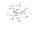
また、実施例1では、第1回転軸I1と第2回転軸I2とを同軸上としたが、図9に示す変形例としてもよい。図9は、実施例1の変形例に係る摩擦撹拌接合装置の一部を模式的に表した概略構成図である。図9に示すように、変形例の第1回転ツール21及び第2回転ツール22は、開先部6の表面及び裏面に対し傾けて配置されている。具体的に、第1回転ツール21の第1回転軸I1は、開先部6の表面に対し直交する第1直交軸J1に対して、所定の角度θ1だけ傾けて配置されている。同様に、第2回転ツール22の第2回転軸I2は、開先部6の裏面に対し直交する第2直交軸J2に対して、所定の角度θ2だけ傾けて配置されている。ここで、角度θ1及び角度θ2は、0°より大きく3°以下となっている。なお、角度θ1及び角度θ2が0°の場合は、実施例1で説明したように、第1回転軸I1及び第2回転軸I2が同軸となる場合である。
In the first embodiment, the first rotation axis I1 and the second rotation axis I2 are coaxial, but a modification shown in FIG. 9 may be used. FIG. 9 is a schematic configuration diagram schematically illustrating a part of the friction stir welding apparatus according to the modification of the first embodiment. As shown in FIG. 9, the first
以上のように、変形例の構成によれば、開先部6の表裏両面に対して、第1回転ツール21の第1回転軸I1及び第2回転ツール22の第2回転軸I2を傾けることができるため、各ショルダ部35,45の各ショルダ面35a,45aが開先部6の表裏両面に対して、傾斜を持った形で当たることから、開先部6を積極的に撹拌することができる。
As described above, according to the configuration of the modification, the first rotation axis I1 of the
次に、図10及び図11を参照して、実施例2に係る摩擦撹拌接合装置100について説明する。図10は、実施例2に係る摩擦撹拌接合装置の一部を模式的に表した概略構成図であり、図11は、実施例2に係る摩擦撹拌工具を部分的に拡大した説明図である。なお、実施例2では、重複した記載を避けるべく、実施例1と異なる部分について説明すると共に、実施例1と同様の構成である部分については、同じ符号を付す。実施例2に係る摩擦撹拌接合装置100は、実施例1の摩擦撹拌接合装置1の突起部33が着脱可能な構成となっている。以下、実施例2に係る摩擦撹拌接合装置100について説明する。
Next, with reference to FIG.10 and FIG.11, the friction
図10に示すように、実施例2に係る摩擦撹拌接合装置100において、摩擦撹拌工具10は、第1回転ツール21と第2回転ツール22との位置が、実施例1の配置と逆となっている。第1回転ツール21は、第1ツール本体31と、第1プローブ102と、突起部103とを有している。第1ツール本体31は、実施例1と同様であるため、説明を省略する。
As shown in FIG. 10, in the friction
第1プローブ102は、第1ツール本体31の第1ショルダ面35aから先端側に突出して設けられており、先端側へ向かって細径となるテーパ形状に形成されている。第1プローブ102は、その先端面102aから後端側に没入する固定穴105が設けられている。このため、第1プローブ102は、その先端面102aが、円環状の面となっている。
The
図10及び図11に示すように、固定穴105は、突起部103を固定するための穴となっている。固定穴105は、第1回転軸I1に直交する面で切った断面が円形となっており、第1回転軸I1を中心軸とする中空円柱形状に形成されている。また、固定穴105は、その内周面に雌ねじのねじ溝が形成されるねじ穴となっている。このため、固定穴には、後述する雄ねじのねじ溝が形成される突起部103が締結される。固定穴105の先端側の縁部には、固定穴105よりも大きな径となるフランジ収容部106が形成されている。フランジ収容部106は、中空円板形状に形成され、突起部103に設けられるフランジ部113を収容する。
As shown in FIGS. 10 and 11, the fixing
突起部103は、先端側の突起本体111と、後端側のねじ部112と、突起本体111とねじ部112との間に設けられるフランジ部113とを有している。突起本体111は、固定穴105から突出(露出)する部位であり、実施例1と同様に、第1回転軸I1に直交する面で切った断面が多角形となっている。ねじ部112は、固定穴105の内部に収容される部位であり、第1回転軸I1に直交する面で切った断面が円形となり、その外周面に雄ねじのねじ溝が形成されている。フランジ部113は、突起本体111及びねじ部112よりも大きな径となっており、ねじ部112の径方向外側に突出し、周方向に沿って円環状に形成されている。
The protruding
上記の突起部103を固定穴105に締結すると、ねじ部112は、固定穴105に収容され、フランジ部113は、フランジ収容部106に収容される。このとき、フランジ部113は、第1回転軸I1の軸方向において、フランジ収容部106の底面に接触する。このため、フランジ部113は、軟化した開先部6の金属が、固定穴105とねじ部112との間に形成される隙間に侵入することを抑制することができる。
When the protruding
また、突起部103は、第2プローブ42よりも硬度の低い材料を用いて構成されている。このため、突起収容部43が形成される第2プローブ42の先端部の剛性は、突起収容部43に収容される突起部103の剛性よりも高くなることから、突起収容部43と突起部103とが接触した場合であっても、突起収容部43への負荷が軽減される。
In addition, the
このように構成された突起部103は、開先部6の厚さに応じて、第1回転軸I1の軸方向における長さの異なる突起本体111が複数種用意されている。つまり、開先部6の厚さが厚いときは、突起本体111の長さが長い突起部103が用いられ、開先部6の厚さが薄いときは、突起本体111の長さが短い突起部103が用いられる。
A plurality of types of protrusion
以上のように、実施例2の構成によれば、突起部103を、第1プローブ102に対し、着脱自在に固定することができるため、突起部103を交換することができる。このため、突起部103が損傷した場合には、新たな突起部103に取り替えることができる。また、開先部6の厚みに応じて、適切な長さとなる突起部103を選定して、第1プローブ32に装着することが可能となる。
As described above, according to the configuration of the second embodiment, since the
また、実施例2の構成によれば、突起部103にフランジ部113を設けることができるため、固定穴105に突起部103を固定した状態において、摩擦により軟化した開先部6の金属が、固定穴105とねじ部112との隙間へ侵入することを、フランジ部113によって抑制することができる。これにより、固定穴105と突起部103とが固着することを抑制することができる。
Further, according to the configuration of the second embodiment, since the
また、実施例2の構成によれば、突起部103を、第2プローブ42よりも硬度の低い材料を用いて構成することができるため、第2プローブ42の突起収容部43に突起部103が接触した場合であっても、交換可能な突起部103によって、第2プローブ42への接触による衝撃を吸収することができる。
Further, according to the configuration of the second embodiment, the
また、実施例2の構成によれば、開先部6の厚さに適した突起部103を選定して、第1プローブ102の固定穴105に取り付けることができる。このため、開先部6の厚さに適した突起部103を用いることで、摩擦撹拌接合を好適に行うことができる。
Further, according to the configuration of the second embodiment, the
次に、図12を参照して、実施例3に係る摩擦撹拌接合装置120について説明する。図12は、実施例3に係る摩擦撹拌接合装置の一部を模式的に表した概略構成図である。なお、実施例3でも、重複した記載を避けるべく、実施例1及び2と異なる部分について説明すると共に、実施例1及び2と同様の構成である部分については、同じ符号を付す。実施例3に係る摩擦撹拌接合装置120は、第1回転ツール21の内部を移動可能な突起ピンが設けられる構成となっている。以下、実施例3に係る摩擦撹拌接合装置120について説明する。
Next, the friction
図12に示すように、実施例3に係る摩擦撹拌接合装置120において、摩擦撹拌工具10は、第1回転ツール21と第2回転ツール22との位置が、実施例1の配置と逆となっている。第1回転ツール21は、第1ツール本体31と、第1プローブ132と、突起ピン133とを有している。第1ツール本体31は、実施例1と同様であるため、説明を省略する。
As shown in FIG. 12, in the friction
第1プローブ132は、第1ツール本体31の第1ショルダ面35aから先端側に突出して設けられており、先端側へ向かって細径となるテーパ形状に形成されている。第1プローブ132は、その先端面132aから後端側に貫通形成される第1挿通穴141が設けられている。このため、第1プローブ132は、その先端面132aが、円環状の面となっている。
The
第1挿通穴141は、突起ピン133を挿通するための穴となっている。第1挿通穴141は、第1プローブ132から第1ツール本体31に亘って貫通形成されている。第1挿通穴141は、第1回転軸I1に直交する面で切った断面が円形となっており、第1回転軸I1を中心軸とする中空円柱形状に形成されている。
The
突起ピン133は、第1回転ツール21の第1挿通穴141に回転自在に挿通され、第1回転軸I1の軸方向に移動自在となっている。突起ピン133は、断面が円形となる円柱形状に形成されている。突起ピン133は、先端側の部位が第1挿通穴141から突出することで、突起部として機能する。なお、突起ピン133は、円柱形状に形成したが、例えば、先端部の断面を多角形とし、後端部の断面を円形としてもよく、先端部の形状と後端部の形状とが異なる形状であってもよい。また、この突起ピン133は、第1ツール本体31及び第1プローブ132とは、独立して回転可能となっている。
The protruding
ここで、突起ピン133と第1挿通穴141との間の隙間は、突起ピン133の先端側が狭く、突起ピン133の後端側が広くなっている。このため、第1回転軸I1に直交する面内において、突起ピン133の先端側は、第1挿通穴141に対し精度良く位置決めされる。一方で、第1回転軸I1に直交する面内において、突起ピン133の後端側は、移動が許容される。
Here, the gap between the projecting
この突起ピン133には、第1挿通穴141内を軸方向に移動させると共に、突起ピン133を回転させる軸移動回転機構145が接続されている。軸移動回転機構145は、制御部20に接続され、制御部20によって軸移動回転機構145が制御されることで、突起ピン133の軸方向への移動と回転とが制御される。
The
第2回転ツール22は、第2ツール本体41と、第2プローブ42と、突起収容部としての第2挿通穴142と、を有している。第2ツール本体41及び第2プローブ42は、実施例1と同様であるため、説明を省略する。
The second
第2挿通穴142は、第2プローブ42の先端面42aから後端側に貫通形成されている。第2挿通穴142は、突起ピン133の先端部を収容するための穴となっている。第2挿通穴142は、第2プローブ42から第2ツール本体41に亘って貫通形成されている。第2挿通穴142は、第2回転軸I2に直交する面で切った断面が円形となっており、第2回転軸I2を中心軸とする中空円柱形状に形成されている。このとき、突起ピン133は、第1挿通穴141と第2挿通穴142とに挿入されることから、第1回転軸I1と第2回転軸I2とが同軸となる。このため、実施例3では、開先部6の表裏両面に対して第1回転軸I1及び第2回転軸I2を傾けることなく、摩擦撹拌接合が行われる。
The
上記のように構成された摩擦撹拌接合装置120を用いて摩擦撹拌接合を行う場合、回転工程S1では、貫通穴8の表裏面側から第1回転ツール21及び第2回転ツール22を挿入した後、第1挿通穴141に収容された突起ピン133を、軸移動回転機構145により先端側に移動させ、第2挿通穴141に挿入する。この時点において、摩擦撹拌工具10と金属板5(二形成される貫通穴8)との間には、隙間が存在する。この後、第1回転ツール21、第2回転ツール22及び突起ピン133を回転させる。このとき、突起ピン133の回転は、第1プローブ132の先端と第2プローブ42の先端との隙間に応じて、適宜変化させてもよい。つまり、隙間が広ければ、突起ピン133の回転数を増大させる一方で、隙間が狭ければ、突起ピン133の回転数を減少させてもよい。
When friction stir welding is performed using the friction
以上のように、実施例3の構成によれば、突起ピン133を第1挿通穴141の内部で移動させて、第2挿通穴142に突起ピン133の先端部を収容させることができる。このため、開先部6の厚さが変わった場合、第1挿通穴141に対する突起ピン133の突出量を変更するだけで、開先部6の厚さに適した長さに簡単に変更することができる。
As described above, according to the configuration of the third embodiment, the
また、実施例3の構成によれば、突起ピン133を第2挿通穴142に挿入することができるため、突起ピン133の第2挿通穴142に対する挿入深さを適切な深さにすることができる。例えば、第2挿通穴142に対する突起ピン133の挿入深さを深くすることで、第1回転ツール21の第1回転軸I1と第2回転ツール22の第2回転軸I2との芯合わせを精度良く行うことができる。一方で、第2挿通穴142に対する突起ピン133の挿入深さを浅くすることで、突起ピン133が僅かに傾いた場合であっても、第2挿通穴142の内部で突起ピン133の傾きを許容できるため、突起ピン133への負荷を抑制することができる。
Further, according to the configuration of the third embodiment, since the
また、実施例3の構成によれば、突起ピン133の先端側において、第1挿通穴141との隙間が狭くなっているため、突起ピン133の先端側における位置決めを精度良く行うことが可能となる。一方で、突起ピン133の後端側において、第1挿通穴141との隙間が広くなっているため、突起ピン133の偏芯等による変形を許容することができ、突起ピン133への負荷を抑制することができる。
Further, according to the configuration of the third embodiment, since the gap with the
なお、実施例3では、第1挿通穴141に挿通された突起ピン133は、第1挿通穴141に対し回転自在となっていたが、この構成に限定されない。突起ピン133と第1挿通穴141とをスプラインで結合し、突起ピン133の軸方向への移動を許容する一方で、突起ピン133の回転方向への移動を不能としてもよい。この構成によれば、突起ピン133の回転を、第1回転ツール21の回転と同期させることができる。
In the third embodiment, the protruding
また、実施例3の構成に、突起ピン133に加わる負荷を検出するピン負荷検出器をさらに設け、突起ピン133を第2貫通穴142に出し入れする際の負荷が小さくなるように、制御部20が軸移動回転機構145を制御してもよい。つまり、制御部20は、ピン負荷検出器により検出した負荷が大きい場合、第1移動機構13または第2移動機構14の少なくとも一方を制御して、突起ピン133への負荷が小さくなるように、上下の回転ツール21,22の相対位置を移動させる。
Further, the configuration of the third embodiment is further provided with a pin load detector for detecting the load applied to the projecting
また、実施例3の摩擦撹拌接合装置120を、図13に示す変形例としてもよい。図13は、実施例3の変形例に係る摩擦撹拌接合装置の一部を模式的に表した概略構成図である。図13に示すように、第2回転ツール22は、第2挿通穴142の内部を移動可能な押出しピン146をさらに有している。この押出しピン146は、摩擦撹拌溶接後において、第2挿通穴142内に侵入する軟化した開先部6の金属を押し出すために使用される。
Further, the friction
押出しピン146は、第2挿通穴142内において、第2回転軸I2の軸方向に移動可能となっている。押出しピン146は、断面が円形となる円柱形状に形成されている。押出しピン146は、先端側の部位が第2挿通穴142から突出する。この押出しピン146には、第2挿通穴142内を軸方向に移動させる軸移動機構147が接続されている。軸移動機構147は、制御部20に接続され、制御部20によって軸移動機構147が制御されることで、押出しピン146の軸方向への移動が制御される。
The
以上のように、変形例の構成によれば、摩擦撹拌接合後において、摩擦により軟化した開先部6の金属が第2挿通穴142に侵入する場合であっても、接合終了時に押出しピン146により軟化した金属を押し出して、第2挿通穴142の外部に排出することができる。このため、第2挿通穴142の内部において、接合完了後、摩擦撹拌工具10の温度が低下した際に軟化した金属が固着することを抑制することができる。
As described above, according to the configuration of the modified example, even after the friction stir welding, even if the metal of the groove portion 6 softened by the friction enters the
また、実施例2及び3の摩擦撹拌接合装置100,120において、接合前もしくは接合中に開先部6の厚みを計測する厚さ計測器をさらに備えてもよい。制御部20は、厚さ計測器により検出した計測結果に基づいて、突起部103の長さ、または突起ピン133の突出量を選定してもよい。この構成によれば、開先部6の厚さに適した突起部103を用いたり、開先部6の厚さに適した突起ピン133の突出量にしたりすることができる。特に、実施例3においては、接合中に開先部6の厚みの計測できる機能を有することで、突起ピン133の突出量を制御して、突出量を好適にして摩擦撹拌工具10の負荷を低減することができる。
In addition, the friction
1 摩擦撹拌接合装置
5 金属板
6 開先部
7 タブ板
8 貫通穴
10 摩擦撹拌工具
11 第1押圧回転機構
12 第2押圧回転機構
13 第1移動機構
14 第2移動機構
15 支持治具
16 工具負荷検出器
20 制御部
21 第1回転ツール
22 第2回転ツール
31 第1ツール本体
32 第1プローブ
33 突起部
35 第1ショルダ部
41 第2ツール本体
42 第2プローブ
43 突起収容部
45 第2ショルダ部
51 第1モータ負荷検出器
52 第2モータ負荷検出器
100 摩擦撹拌接合装置(実施例2)
102 第1プローブ(実施例2)
103 突起部(実施例2)
105 固定穴
106 フランジ収容部
111 突起本体
112 ねじ部
113 フランジ部
120 摩擦撹拌接合装置(実施例3)
132 第1プローブ(実施例3)
133 突起ピン
141 第1挿通穴
142 第2挿通穴
145 軸移動回転機構
146 押出しピン
147 軸移動機構
I1 第1回転軸
I2 第2回転軸
DESCRIPTION OF SYMBOLS 1 Friction
102 1st probe (Example 2)
103 Protrusion (Example 2)
105
132 First probe (Example 3)
133
Claims (31)
前記被接合部を挟んで他方側に配置され、前記第1回転ツールに対向して設けられる第2回転ツールと、を備え、
前記第1回転ツールは、
前記被接合部の一方側の面と接する第1ショルダ部を有する第1ツール本体と、
前記第1ツール本体から前記第2回転ツールに向かって突出する第1プローブと、
前記第1プローブから前記第2回転ツールに向かって突出する突起部と、を有し、
前記第2回転ツールは、
前記被接合部の他方側の面と接する第2ショルダ部を有する第2ツール本体と、
前記第2ツール本体から前記第1回転ツールに向かって突出する第2プローブと、
前記第2プローブに設けられ、前記第1回転ツールの前記突起部を収容可能な突起収容部と、を有することを特徴とする摩擦撹拌工具。 A first rotating tool disposed on one side of the bonded portion with respect to the bonded portion of the member ;
A second rotating tool that is disposed on the other side across the bonded portion and provided opposite to the first rotating tool,
The first rotating tool is:
A first tool body having a first shoulder portion in contact with a surface on one side of the joined portion;
A first probe protruding from the first tool body toward the second rotating tool;
A protrusion protruding from the first probe toward the second rotating tool,
The second rotation tool is:
A second tool body having a second shoulder portion in contact with the other surface of the joined portion;
A second probe protruding from the second tool body toward the first rotating tool;
A friction stir tool provided on the second probe and having a protrusion accommodating portion capable of accommodating the protrusion of the first rotating tool.
前記第1回転ツール及び前記第2回転ツールは、前記被接合部の溶接時において、前記突起収容部に前記突起部の少なくとも一部を収容した状態で回転させられることを特徴とする請求項1から7のいずれか1項に記載の摩擦撹拌工具。 When the thickness of the bonded portion is a maximum thickness assumed in advance,
The first rotating tool and the second rotating tool are rotated in a state in which at least a part of the protrusion is accommodated in the protrusion accommodating portion during welding of the bonded portion. The friction stir tool of any one of 7 to 7 .
前記突起部は、前記固定穴の外側に突出し、前記第1プローブに接触するフランジ部を有することを特徴とする請求項10に記載の摩擦撹拌工具。 The first probe further includes a fixing hole for fixing the protrusion,
The friction stir tool according to claim 10 , wherein the protruding portion has a flange portion that protrudes outside the fixing hole and contacts the first probe.
前記第1回転ツールの回転軸に沿って、前記第1プローブに貫通形成される第1挿通穴と、
前記第1挿通穴の内部を移動可能な突起ピンと、を有し、
前記突起部は、前記第1挿通穴から突出する前記突起ピンの一部であることを特徴とする請求項1から8のいずれか1項に記載の摩擦撹拌工具。 The first rotating tool is:
A first insertion hole formed through the first probe along the rotation axis of the first rotation tool;
A projecting pin movable within the first insertion hole,
The friction stir tool according to any one of claims 1 to 8 , wherein the protrusion is a part of the protrusion pin protruding from the first insertion hole.
前記第2挿通穴の内部を移動可能な押出しピンを、さらに有することを特徴とする請求項15に記載の摩擦撹拌工具。 The second rotation tool is:
The friction stir tool according to claim 15 , further comprising an extruding pin movable within the second insertion hole.
前記摩擦撹拌工具の前記第1回転ツールの前記第1ショルダ部を前記被接合部の一方側の面に押し当てた状態で、前記第1回転ツールを回転させる第1押圧回転機構と、
前記摩擦撹拌工具の前記第2回転ツールの前記第2ショルダ部を前記被接合部の他方側の面に押し当てた状態で、前記第2回転ツールを回転させる第2押圧回転機構と、
前記部材に対し、前記第1回転ツールを前記部材の前記被接合部に沿って移動させる第1移動機構と、
前記部材に対し、前記第2回転ツールを前記部材の前記被接合部に沿って移動させる第2移動機構と、
前記第1押圧回転機構、前記第2押圧回転機構、前記第1移動機構及び前記第2移動機構を制御する制御部と、を備えることを特徴とする摩擦撹拌接合装置。 The friction stir tool according to any one of claims 1 to 20 ,
A first pressing and rotating mechanism that rotates the first rotating tool in a state in which the first shoulder portion of the first rotating tool of the friction stir tool is pressed against one surface of the joined portion;
A second pressing and rotating mechanism for rotating the second rotating tool in a state in which the second shoulder portion of the second rotating tool of the friction stir tool is pressed against the other surface of the joined portion;
With respect to the member, a first moving mechanism for moving said first rotary tool along the bonding portion of the member,
With respect to the member, and a second moving mechanism for moving the second rotating tool along said bonding portion of said member,
A friction stir welding apparatus comprising: the first pressing rotation mechanism, the second pressing rotation mechanism, the first movement mechanism, and a control unit that controls the second movement mechanism.
前記制御部は、前記工具負荷検出器の検出結果に基づいて、前記摩擦撹拌工具の負荷が小さくなるように、前記第1押圧回転機構、前記第2押圧回転機構、前記第1移動機構及び前記第2移動機構の少なくとも1つを制御することを特徴とする請求項21または22に記載の摩擦撹拌接合装置。 A tool load detector for detecting the load of the friction stir tool, further comprising:
The control unit is configured to reduce the load on the friction stir tool based on the detection result of the tool load detector, so that the first press rotation mechanism, the second press rotation mechanism, the first movement mechanism, and the The friction stir welding apparatus according to claim 21 or 22 , wherein at least one of the second moving mechanisms is controlled.
前記制御部は、前記第1動力負荷検出器により検出された負荷と、前記第2動力負荷検出器により検出された負荷との差分が小さくなるように、前記第1移動機構及び前記第2移動機構の少なくとも一方を制御することを特徴とする請求項23に記載の摩擦撹拌接合装置。 The tool load detector includes a first power load detector that detects a load applied to the power source of the first moving mechanism, and a second power load detector that detects a load applied to the power source of the second moving mechanism. Have
The controller is configured to reduce the difference between the load detected by the first power load detector and the load detected by the second power load detector, so that the first movement mechanism and the second movement are reduced. The friction stir welding apparatus according to claim 23 , wherein at least one of the mechanisms is controlled.
前記制御部は、前記歪み検出器により検出された歪みが小さくなるように、前記第1移動機構及び前記第2移動機構の少なくとも一方を制御することを特徴とする請求項23に記載の摩擦撹拌接合装置。 The tool load detector has a strain detector that detects a strain of a rotation axis of at least one of the first rotating tool and the second rotating tool,
The friction stirrer according to claim 23 , wherein the control unit controls at least one of the first moving mechanism and the second moving mechanism so that the strain detected by the strain detector is reduced. Joining device.
前記制御部は、前記作動音検出器により検出された作動音が小さくなるように、前記第1移動機構及び前記第2移動機構の少なくとも一方を制御することを特徴とする請求項23に記載の摩擦撹拌接合装置。 The tool load detector has an operation sound detector for detecting an operation sound of the friction stir tool,
24. The control unit according to claim 23 , wherein the control unit controls at least one of the first movement mechanism and the second movement mechanism so that an operation sound detected by the operation sound detector is reduced. Friction stir welding device.
前記制御部は、前記振動検出器により検出された振動モードが、前記第1回転ツール及び前記第2回転ツールの少なくとも一方に負荷が加わったときの負荷振動モードである場合、前記負荷振動モード以外の振動モードとなるように、前記第1移動機構及び前記第2移動機構の少なくとも一方を制御することを特徴とする請求項23に記載の摩擦撹拌接合装置。 The tool load detector includes a vibration detector that detects vibration of at least one of the first rotating tool and the second rotating tool,
When the vibration mode detected by the vibration detector is a load vibration mode when a load is applied to at least one of the first rotation tool and the second rotation tool, the control unit is not in the load vibration mode. 24. The friction stir welding apparatus according to claim 23 , wherein at least one of the first moving mechanism and the second moving mechanism is controlled so as to be in the vibration mode.
接合開始点に予め貫通形成された貫通穴に対し、前記貫通穴の一方側から前記第1回転ツールを挿入し、前記貫通穴の他方側から前記第2回転ツールを挿入すると共に、前記第1回転ツールの前記突起部を、前記第2回転ツールの前記突起収容部に収容させ、前記第1回転ツールと前記第2回転ツールとを回転させる回転工程と、
前記第1回転ツールと前記第2回転ツールとの差し込み位置を相対的に調整する位置調整工程と、
前記第1回転ツール及び前記第2回転ツールを前記部材の前記被接合部に沿って前記接合開始点から接合終了点まで移動させる移動工程と、
前記接合終了点において、前記第1回転ツール及び前記第2回転ツールを回転させた状態で、前記第1回転ツール及び前記第2回転ツールを前記被接合部から引き抜く引抜工程と、を備えることを特徴とする摩擦撹拌接合方法。 A friction stir welding method for welding the joined portion of the member using the friction stir tool according to any one of claims 1 to 20 ,
The first rotary tool is inserted from one side of the through hole, the second rotary tool is inserted from the other side of the through hole, and the first rotary tool is inserted into the through hole formed in advance at the joining start point. A rotating step of accommodating the protrusion of the rotating tool in the protrusion accommodating portion of the second rotating tool and rotating the first rotating tool and the second rotating tool;
A position adjusting step of relatively adjusting the insertion position of the first rotating tool and the second rotating tool;
A moving step of moving the first rotary tool and the second rotary tool from the joining start point to the joining end point along the joined portion of the member ;
A drawing step of pulling out the first rotating tool and the second rotating tool from the joined portion in a state where the first rotating tool and the second rotating tool are rotated at the joining end point. Friction stir welding method characterized.
Priority Applications (5)
| Application Number | Priority Date | Filing Date | Title |
|---|---|---|---|
| JP2013202758A JP6155155B2 (en) | 2013-09-27 | 2013-09-27 | Friction stir tool, friction stir welding apparatus, and friction stir welding method |
| US14/904,501 US20160167161A1 (en) | 2013-09-27 | 2014-06-04 | Friction stirring tool, friction stir welding device and friction stir welding method |
| EP14847909.0A EP3009222B1 (en) | 2013-09-27 | 2014-06-04 | Friction stirring tool, friction stir welding device and friction stir welding method |
| PCT/JP2014/064866 WO2015045490A1 (en) | 2013-09-27 | 2014-06-04 | Friction stirring tool, friction stir welding device and friction stir welding method |
| US16/534,578 US20190358741A1 (en) | 2013-09-27 | 2019-08-07 | Friction stirring tool, friction stir welding device and friction stir welding method |
Applications Claiming Priority (1)
| Application Number | Priority Date | Filing Date | Title |
|---|---|---|---|
| JP2013202758A JP6155155B2 (en) | 2013-09-27 | 2013-09-27 | Friction stir tool, friction stir welding apparatus, and friction stir welding method |
Publications (3)
| Publication Number | Publication Date |
|---|---|
| JP2015066575A JP2015066575A (en) | 2015-04-13 |
| JP2015066575A5 JP2015066575A5 (en) | 2016-08-04 |
| JP6155155B2 true JP6155155B2 (en) | 2017-06-28 |
Family
ID=52742648
Family Applications (1)
| Application Number | Title | Priority Date | Filing Date |
|---|---|---|---|
| JP2013202758A Expired - Fee Related JP6155155B2 (en) | 2013-09-27 | 2013-09-27 | Friction stir tool, friction stir welding apparatus, and friction stir welding method |
Country Status (4)
| Country | Link |
|---|---|
| US (2) | US20160167161A1 (en) |
| EP (1) | EP3009222B1 (en) |
| JP (1) | JP6155155B2 (en) |
| WO (1) | WO2015045490A1 (en) |
Families Citing this family (12)
| Publication number | Priority date | Publication date | Assignee | Title |
|---|---|---|---|---|
| GB2526121B (en) * | 2014-05-14 | 2017-02-01 | Acergy France SAS | Fabrication of pipe strings using friction stir welding |
| GB2526122B (en) * | 2014-05-14 | 2016-09-14 | Acergy France SAS | Fabrication of pipe strings using friction stir welding |
| JP6284444B2 (en) * | 2014-06-25 | 2018-02-28 | 三菱重工業株式会社 | Friction stir welding method and friction stir welding apparatus |
| JP6403515B2 (en) * | 2014-09-24 | 2018-10-10 | 三菱重工業株式会社 | Joint processing method and dome member |
| EP3059028A1 (en) * | 2015-02-20 | 2016-08-24 | Siemens Aktiengesellschaft | Cast iron part with a metallic functional area |
| US11590605B2 (en) * | 2017-05-11 | 2023-02-28 | Nippon Light Metal Company, Ltd. | Joining method |
| JP2020015294A (en) * | 2018-07-27 | 2020-01-30 | 宏二 上谷 | Method for laying cooling block on mold main body |
| CN109551097A (en) * | 2018-12-10 | 2019-04-02 | 上海航天设备制造总厂有限公司 | A kind of static shaft shoulder friction stir welding method of the coaxial added material of bevel |
| CN113260478A (en) * | 2019-03-01 | 2021-08-13 | 川崎重工业株式会社 | Friction stir spot welding device, and object to be welded and shoulder member which are friction stir spot welded |
| EP4129538A4 (en) * | 2020-06-30 | 2024-04-17 | Citizen Watch Co Ltd | Machine tool and method for controlling machine tool |
| CN113172333B (en) * | 2021-05-31 | 2022-08-09 | 四川航天长征装备制造有限公司 | Friction stir welding stirring head capable of improving penetration depth |
| CN114226950A (en) * | 2021-12-13 | 2022-03-25 | 北京碳垣新材料科技有限公司 | Thick plate welding stirring head and thick plate welding equipment |
Family Cites Families (18)
| Publication number | Priority date | Publication date | Assignee | Title |
|---|---|---|---|---|
| US6227430B1 (en) * | 1998-04-30 | 2001-05-08 | The Boeing Company | FSW tool design for thick weld joints |
| JP2001340976A (en) * | 2000-05-31 | 2001-12-11 | Showa Denko Kk | Friction stir connecting tool and friction stir connecting method |
| EP1372899B1 (en) * | 2001-03-29 | 2005-10-26 | Mazda Motor Corporation | Joining method and apparatus using frictional agitation |
| US6669075B2 (en) * | 2002-05-07 | 2003-12-30 | Concurrent Technologies Corporation | Tapered friction stir welding tool |
| US20040013405A1 (en) * | 2002-07-18 | 2004-01-22 | Christiansen Robert D | Method for preparing/printing video scene indices |
| JP3726786B2 (en) * | 2002-07-31 | 2005-12-14 | マツダ株式会社 | Joining method and joining tool |
| US20060175382A1 (en) * | 2003-11-10 | 2006-08-10 | Packer Scott M | Tool geometries for friction stir spot welding of high melting temperature alloys |
| US6994242B2 (en) * | 2003-12-09 | 2006-02-07 | The Boeing Company | Friction stir weld tool and method |
| US8016179B2 (en) * | 2006-07-17 | 2011-09-13 | Wichita State University | Friction stir welding tool having a scroll-free concentric region |
| CN102248277B (en) * | 2006-10-02 | 2013-04-24 | 日本轻金属株式会社 | Method of friction Stirring |
| JP4838385B2 (en) | 2009-08-31 | 2011-12-14 | 三菱日立製鉄機械株式会社 | Double-side friction stir welding method, joining apparatus, metal plate joining method for cold rolling equipment, and cold rolling equipment |
| BR112012012017B1 (en) * | 2009-11-18 | 2017-06-27 | Mitsubishi-Hitachi Metals Machinery, Inc. | METHOD AND WELDING APPARATUS FOR TWO-SIDE SHAKING AND ATTRACTION, AND, TWO-SIDE SHAKING AND TWILIGHT ATTACHMENT TOOLS ASSEMBLY |
| US20110309131A1 (en) * | 2010-06-18 | 2011-12-22 | Battelle Memorial Institute | Friction stir welding tool and process for welding dissimilar materials |
| WO2012029175A1 (en) | 2010-09-03 | 2012-03-08 | 三菱日立製鉄機械株式会社 | Double-side friction stir welding method for metal plates having gap between abutting portions |
| JP2012245542A (en) * | 2011-05-27 | 2012-12-13 | Mitsubishi Heavy Ind Ltd | Friction stir welding tool and friction stir welding apparatus |
| WO2013043877A1 (en) * | 2011-09-23 | 2013-03-28 | Burford Dwight A | Mandrel tool probe for friction stir welding |
| JP6076004B2 (en) * | 2012-09-06 | 2017-02-08 | 株式会社Uacj | Rotating tool for friction stir spot welding and friction stir spot welding method using the same |
| JP6284444B2 (en) * | 2014-06-25 | 2018-02-28 | 三菱重工業株式会社 | Friction stir welding method and friction stir welding apparatus |
-
2013
- 2013-09-27 JP JP2013202758A patent/JP6155155B2/en not_active Expired - Fee Related
-
2014
- 2014-06-04 US US14/904,501 patent/US20160167161A1/en not_active Abandoned
- 2014-06-04 WO PCT/JP2014/064866 patent/WO2015045490A1/en active Application Filing
- 2014-06-04 EP EP14847909.0A patent/EP3009222B1/en active Active
-
2019
- 2019-08-07 US US16/534,578 patent/US20190358741A1/en not_active Abandoned
Also Published As
| Publication number | Publication date |
|---|---|
| EP3009222A4 (en) | 2016-09-21 |
| US20160167161A1 (en) | 2016-06-16 |
| US20190358741A1 (en) | 2019-11-28 |
| WO2015045490A1 (en) | 2015-04-02 |
| EP3009222A1 (en) | 2016-04-20 |
| EP3009222B1 (en) | 2021-02-17 |
| JP2015066575A (en) | 2015-04-13 |
Similar Documents
| Publication | Publication Date | Title |
|---|---|---|
| JP6155155B2 (en) | Friction stir tool, friction stir welding apparatus, and friction stir welding method | |
| JP2015066575A5 (en) | ||
| JP5588385B2 (en) | Friction stir spot welding apparatus and friction stir spot welding method | |
| KR101862972B1 (en) | Method and device for friction stir welding | |
| WO2016063538A1 (en) | Friction stir spot welding device and friction stir spot welding method | |
| JP5987398B2 (en) | Friction stir welding equipment | |
| JP4838388B2 (en) | Double-side friction stir welding method and apparatus and double-side friction stir welding tool set | |
| US20050103824A1 (en) | Method and apparatus for friction stir welding | |
| EP2703110A1 (en) | Friction stir welding method and device, and tool set | |
| JP5987397B2 (en) | Friction stir welding equipment | |
| JP6014205B2 (en) | Friction stir spot welding apparatus and friction stir spot welding method | |
| WO2017047574A1 (en) | Friction stir spot welding device and friction stir spot welding method | |
| WO2020179661A1 (en) | Joining device for friction stirring point, joined article having joined friction stirring point, and shoulder member | |
| JP5701838B2 (en) | How to join a plastic workpiece to another workpiece | |
| JP2011115857A (en) | Friction stir welding device | |
| JP2000033484A (en) | Penetrating frictional agitation joining probe | |
| JP2012250277A (en) | Rotary tool for friction stir welding, friction stir welding device, and friction stir welding method | |
| JP4175484B2 (en) | Friction stir welding method and its joining apparatus and friction joined body | |
| JP2016028227A (en) | Inspection system for inspecting object by utilizing force sensor | |
| JP2004298900A (en) | Friction stir welding method, its welding equipment, and friction welding body | |
| JP2019206026A (en) | Friction stir welding apparatus and manufacturing method for cooler | |
| JP2004322198A (en) | Method and apparatus for calculating joining strength of each joining member | |
| JP2004050234A (en) | Method and device for controlling rotary tool of friction stir joining | |
| WO2022118586A1 (en) | Joining device and joining method | |
| JP2007083257A (en) | Friction stirring and joining method using double action type rotary tool |
Legal Events
| Date | Code | Title | Description |
|---|---|---|---|
| A521 | Request for written amendment filed |
Free format text: JAPANESE INTERMEDIATE CODE: A523 Effective date: 20160614 |
|
| A621 | Written request for application examination |
Free format text: JAPANESE INTERMEDIATE CODE: A621 Effective date: 20160614 |
|
| TRDD | Decision of grant or rejection written | ||
| A01 | Written decision to grant a patent or to grant a registration (utility model) |
Free format text: JAPANESE INTERMEDIATE CODE: A01 Effective date: 20170509 |
|
| A61 | First payment of annual fees (during grant procedure) |
Free format text: JAPANESE INTERMEDIATE CODE: A61 Effective date: 20170605 |
|
| R150 | Certificate of patent or registration of utility model |
Ref document number: 6155155 Country of ref document: JP Free format text: JAPANESE INTERMEDIATE CODE: R150 |
|
| LAPS | Cancellation because of no payment of annual fees |