KR20230012022A - Battery management device, battery management method - Google Patents
Battery management device, battery management method Download PDFInfo
- Publication number
- KR20230012022A KR20230012022A KR1020227044015A KR20227044015A KR20230012022A KR 20230012022 A KR20230012022 A KR 20230012022A KR 1020227044015 A KR1020227044015 A KR 1020227044015A KR 20227044015 A KR20227044015 A KR 20227044015A KR 20230012022 A KR20230012022 A KR 20230012022A
- Authority
- KR
- South Korea
- Prior art keywords
- battery
- parameter
- internal resistance
- difference
- calculation unit
- Prior art date
Links
Images


Classifications
-
- H—ELECTRICITY
- H02—GENERATION; CONVERSION OR DISTRIBUTION OF ELECTRIC POWER
- H02J—CIRCUIT ARRANGEMENTS OR SYSTEMS FOR SUPPLYING OR DISTRIBUTING ELECTRIC POWER; SYSTEMS FOR STORING ELECTRIC ENERGY
- H02J7/00—Circuit arrangements for charging or depolarising batteries or for supplying loads from batteries
- H02J7/0047—Circuit arrangements for charging or depolarising batteries or for supplying loads from batteries with monitoring or indicating devices or circuits
- H02J7/005—Detection of state of health [SOH]
-
- H—ELECTRICITY
- H01—ELECTRIC ELEMENTS
- H01M—PROCESSES OR MEANS, e.g. BATTERIES, FOR THE DIRECT CONVERSION OF CHEMICAL ENERGY INTO ELECTRICAL ENERGY
- H01M10/00—Secondary cells; Manufacture thereof
- H01M10/42—Methods or arrangements for servicing or maintenance of secondary cells or secondary half-cells
- H01M10/425—Structural combination with electronic components, e.g. electronic circuits integrated to the outside of the casing
-
- G—PHYSICS
- G01—MEASURING; TESTING
- G01R—MEASURING ELECTRIC VARIABLES; MEASURING MAGNETIC VARIABLES
- G01R31/00—Arrangements for testing electric properties; Arrangements for locating electric faults; Arrangements for electrical testing characterised by what is being tested not provided for elsewhere
- G01R31/36—Arrangements for testing, measuring or monitoring the electrical condition of accumulators or electric batteries, e.g. capacity or state of charge [SoC]
- G01R31/367—Software therefor, e.g. for battery testing using modelling or look-up tables
-
- G—PHYSICS
- G01—MEASURING; TESTING
- G01R—MEASURING ELECTRIC VARIABLES; MEASURING MAGNETIC VARIABLES
- G01R31/00—Arrangements for testing electric properties; Arrangements for locating electric faults; Arrangements for electrical testing characterised by what is being tested not provided for elsewhere
- G01R31/36—Arrangements for testing, measuring or monitoring the electrical condition of accumulators or electric batteries, e.g. capacity or state of charge [SoC]
- G01R31/389—Measuring internal impedance, internal conductance or related variables
-
- G—PHYSICS
- G01—MEASURING; TESTING
- G01R—MEASURING ELECTRIC VARIABLES; MEASURING MAGNETIC VARIABLES
- G01R31/00—Arrangements for testing electric properties; Arrangements for locating electric faults; Arrangements for electrical testing characterised by what is being tested not provided for elsewhere
- G01R31/36—Arrangements for testing, measuring or monitoring the electrical condition of accumulators or electric batteries, e.g. capacity or state of charge [SoC]
- G01R31/392—Determining battery ageing or deterioration, e.g. state of health
-
- H—ELECTRICITY
- H01—ELECTRIC ELEMENTS
- H01M—PROCESSES OR MEANS, e.g. BATTERIES, FOR THE DIRECT CONVERSION OF CHEMICAL ENERGY INTO ELECTRICAL ENERGY
- H01M10/00—Secondary cells; Manufacture thereof
- H01M10/42—Methods or arrangements for servicing or maintenance of secondary cells or secondary half-cells
- H01M10/48—Accumulators combined with arrangements for measuring, testing or indicating the condition of cells, e.g. the level or density of the electrolyte
- H01M10/482—Accumulators combined with arrangements for measuring, testing or indicating the condition of cells, e.g. the level or density of the electrolyte for several batteries or cells simultaneously or sequentially
-
- H—ELECTRICITY
- H01—ELECTRIC ELEMENTS
- H01M—PROCESSES OR MEANS, e.g. BATTERIES, FOR THE DIRECT CONVERSION OF CHEMICAL ENERGY INTO ELECTRICAL ENERGY
- H01M10/00—Secondary cells; Manufacture thereof
- H01M10/42—Methods or arrangements for servicing or maintenance of secondary cells or secondary half-cells
- H01M10/48—Accumulators combined with arrangements for measuring, testing or indicating the condition of cells, e.g. the level or density of the electrolyte
- H01M10/486—Accumulators combined with arrangements for measuring, testing or indicating the condition of cells, e.g. the level or density of the electrolyte for measuring temperature
-
- G—PHYSICS
- G01—MEASURING; TESTING
- G01R—MEASURING ELECTRIC VARIABLES; MEASURING MAGNETIC VARIABLES
- G01R31/00—Arrangements for testing electric properties; Arrangements for locating electric faults; Arrangements for electrical testing characterised by what is being tested not provided for elsewhere
- G01R31/36—Arrangements for testing, measuring or monitoring the electrical condition of accumulators or electric batteries, e.g. capacity or state of charge [SoC]
- G01R31/382—Arrangements for monitoring battery or accumulator variables, e.g. SoC
- G01R31/3842—Arrangements for monitoring battery or accumulator variables, e.g. SoC combining voltage and current measurements
-
- H—ELECTRICITY
- H01—ELECTRIC ELEMENTS
- H01M—PROCESSES OR MEANS, e.g. BATTERIES, FOR THE DIRECT CONVERSION OF CHEMICAL ENERGY INTO ELECTRICAL ENERGY
- H01M10/00—Secondary cells; Manufacture thereof
- H01M10/42—Methods or arrangements for servicing or maintenance of secondary cells or secondary half-cells
- H01M10/425—Structural combination with electronic components, e.g. electronic circuits integrated to the outside of the casing
- H01M2010/4271—Battery management systems including electronic circuits, e.g. control of current or voltage to keep battery in healthy state, cell balancing
-
- H—ELECTRICITY
- H02—GENERATION; CONVERSION OR DISTRIBUTION OF ELECTRIC POWER
- H02J—CIRCUIT ARRANGEMENTS OR SYSTEMS FOR SUPPLYING OR DISTRIBUTING ELECTRIC POWER; SYSTEMS FOR STORING ELECTRIC ENERGY
- H02J7/00—Circuit arrangements for charging or depolarising batteries or for supplying loads from batteries
- H02J7/0047—Circuit arrangements for charging or depolarising batteries or for supplying loads from batteries with monitoring or indicating devices or circuits
- H02J7/0048—Detection of remaining charge capacity or state of charge [SOC]
-
- Y—GENERAL TAGGING OF NEW TECHNOLOGICAL DEVELOPMENTS; GENERAL TAGGING OF CROSS-SECTIONAL TECHNOLOGIES SPANNING OVER SEVERAL SECTIONS OF THE IPC; TECHNICAL SUBJECTS COVERED BY FORMER USPC CROSS-REFERENCE ART COLLECTIONS [XRACs] AND DIGESTS
- Y02—TECHNOLOGIES OR APPLICATIONS FOR MITIGATION OR ADAPTATION AGAINST CLIMATE CHANGE
- Y02E—REDUCTION OF GREENHOUSE GAS [GHG] EMISSIONS, RELATED TO ENERGY GENERATION, TRANSMISSION OR DISTRIBUTION
- Y02E60/00—Enabling technologies; Technologies with a potential or indirect contribution to GHG emissions mitigation
- Y02E60/10—Energy storage using batteries
Landscapes
- Engineering & Computer Science (AREA)
- Physics & Mathematics (AREA)
- General Physics & Mathematics (AREA)
- Manufacturing & Machinery (AREA)
- Chemical & Material Sciences (AREA)
- Chemical Kinetics & Catalysis (AREA)
- Electrochemistry (AREA)
- General Chemical & Material Sciences (AREA)
- Microelectronics & Electronic Packaging (AREA)
- Health & Medical Sciences (AREA)
- General Health & Medical Sciences (AREA)
- Medical Informatics (AREA)
- Power Engineering (AREA)
- Secondary Cells (AREA)
- Charge And Discharge Circuits For Batteries Or The Like (AREA)
- Electric Propulsion And Braking For Vehicles (AREA)
- Tests Of Electric Status Of Batteries (AREA)
Abstract
본 발명은, 전지의 내부 저항과 열화 상태를 동시에 또한 단시간에 간이한 수단에 의해 측정할 수 있는 기술을 제공하는 것을 목적으로 한다. 본 발명에 관한 전지 관리 장치는, 충전 또는 방전을 종료한 종료 시점 이후의 제1 기산 시점에 있어서의 상기 전압과, 상기 제1 기산 시점으로부터 제1 기간이 경과한 제1 시점에 있어서의 상기 전압 사이의 제1 차분을 취득하고, 또한, 상기 제1 시점 이후의 제2 기산 시점에 있어서의 상기 전압과, 상기 제2 기산 시점으로부터 제2 기간이 경과한 제2 시점에 있어서의 상기 전압 사이의 제2 차분을 취득하고, 상기 제1 차분과 상기 전지의 내부 저항 사이의 관계에 따라서 상기 내부 저항을 추정하고, 상기 제2 차분과 상기 전지의 열화 상태 사이의 관계에 따라서 상기 열화 상태를 추정한다(도 7 참조).An object of the present invention is to provide a technique capable of measuring the internal resistance and deterioration state of a battery simultaneously and in a short time by a simple means. The battery management device according to the present invention relates to the voltage at a first calculated time point after the end of charging or discharging, and the voltage at a first time point after a first period elapses from the first calculated time point. and obtains a first difference between the voltage at a second calculated time point after the first time point and the voltage at a second time point at which a second period has elapsed from the second calculated time point. Obtaining a second difference, estimating the internal resistance according to the relationship between the first difference and the internal resistance of the battery, and estimating the deterioration state according to the relationship between the second difference and the deterioration state of the battery (See Fig. 7).
Description
본 발명은, 전지의 상태를 관리하는 기술에 관한 것이다.The present invention relates to a technique for managing the state of a battery.
시장에 있어서의 축전지의 수는 계속해서 증가하고 있다. 전지가 열화되면, 총 충전 용량이 저하된다. 이 상태는, 전지의 열화 상태(State of Health: SOH)로서 표현된다. 전지가 열화되면, 전지의 내부 저항 Ri도 증가된다. SOH와 Ri에 기초하여 전지 상태를 평가함으로써, 적절한 유스 케이스를 결정할 수 있다.The number of accumulators on the market continues to increase. When the battery deteriorates, the total charge capacity decreases. This state is expressed as a state of deterioration (State of Health: SOH) of the battery. When the battery deteriorates, the battery's internal resistance Ri also increases. By evaluating the state of the cell based on SOH and Ri, an appropriate use case can be determined.
하기 특허문헌 1은, 『내부 저항 추정값의 정밀도를 향상시킬 수 있고, 나아가서는 배터리 용량인 SOC의 산출 정밀도를 향상시킬 수 있는 배터리의 내부 저항 성분 추정 방법을 제공하는 것.』을 과제로 하여, 『복수의 단위 전지로 구성한 배터리(5)의 내부 저항 성분 추정 방법이며, 배터리(5)의 내부 저항 성분에, 배터리(5)의 내부에서의 이온 물질의 확산 이동에 의한 편재로 발생하는 전압을 고려한 확산 분극 저항을 설정하고, 확산 물질의 농도의 시간 변화를 사용하여, 확산 분극 저항을 추정하였다.』고 하는 기술을 개시하고 있다(요약 참조).
하기 특허문헌 2는, 『SOC 및 SOH를 전지의 프로세스값뿐만 아니라, SOC 및 SOH의 상호 상관도 고려하여 고정밀도로 추정한다.』는 것을 과제로 하여, 『배터리 컨트롤러(6BC)에 있어서, BCIA(9)는, 전지(5)의 내부 저항의 25℃ 환산값 R25를 계측하는 내부 저항 계측부(96) 및 개방 전압의 25℃ 환산값 OCV25를 계측하는 개방 전압 계측부(97)를 구비한다. CPU(8)는, OCV25와 SOH 및 SOC의 관계를 나타내는 제1 방정식 및 R25와 SOH 및 SOC의 관계를 나타내는 제2 방정식을 기억하는 방정식 기억부(86) 그리고 상기 R25 및 OCV25의 계측 결과를 상기 각 방정식에 적용하고, 그 연립 방정식의 해로서 SOH 및 SOC를 구하는 구해부(87)를 구비한다.』고 하는 기술을 개시하고 있다(요약 참조).
하기 특허문헌 3은, 『이차 전지(10)의 특성을 평가하는 간단한 구성의 전지 시스템(1)을 제공한다.』는 것을 과제로 하여, 『전지 시스템(1)은, 정극(11)과 부극(15)과 전해질(12, 14)을 갖는 이차 전지(10)와, 초기 저항값 및 평가 주파수를 포함하는 미리 측정된 이차 전지(10)의 고유 정보를 기억하는 기억부(23)와, 기억부(23)에 기억되어 있는 평가 주파수의 교류 신호를 이차 전지(10)에 인가하는 전원부(20)와, 교류 신호로부터 이차 전지(10)의 고체 전해질 계면 피막(17)의 임피던스를 측정하는 측정부(22)와, 상기 임피던스 및 고유 정보로부터 이차 전지(10)의 열화도 또는 충전 심도 중 적어도 어느 것을 산출하는 산출부(24)를 구비한다. 』고 하는 기술을 개시하고 있다(요약 참조).Patent Literature 3 below sets "providing a
특허문헌 1에 있어서는, 내부 저항만을 측정하므로, SOH를 측정하기 위한 기술이 별도로 필요해진다. 특허문헌 2에 있어서는, 개회로 전압(Open Circuit Voltage: OCV)을 사용하여 Ri나 SOH를 측정한다. 그러나 OCV를 사용하는 방법은, 측정 시간이 긴 경향이 있다. 특허문헌 3에 있어서는, 임피던스를 측정하기 위한 파형을 생성하는 파형 생성기가 별도로 필요해진다.In
본 발명은, 상기와 같은 과제를 감안하여 이루어진 것이며, 전지의 내부 저항과 열화 상태를 동시에 또한 단시간에 간이한 수단에 의해 측정할 수 있는 기술을 제공하는 것을 목적으로 한다.The present invention has been made in view of the above problems, and an object of the present invention is to provide a technique capable of measuring the internal resistance and deterioration state of a battery simultaneously and in a short time by a simple means.
본 발명에 관한 전지 관리 장치는, 충전 또는 방전을 종료한 종료 시점 이후의 제1 기산 시점에 있어서의 상기 전압과, 상기 제1 기산 시점으로부터 제1 기간이 경과한 제1 시점에 있어서의 상기 전압 사이의 제1 차분을 취득하고, 또한, 상기 제1 시점 이후의 제2 기산 시점에 있어서의 상기 전압과, 상기 제2 기산 시점으로부터 제2 기간이 경과한 제2 시점에 있어서의 상기 전압 사이의 제2 차분을 취득하고, 상기 제1 차분과 상기 전지의 내부 저항 사이의 관계에 따라서 상기 내부 저항을 추정하고, 상기 제2 차분과 상기 전지의 열화 상태 사이의 관계에 따라서 상기 열화 상태를 추정한다.The battery management device according to the present invention relates to the voltage at a first calculated time point after the end of charging or discharging, and the voltage at a first time point after a first period elapses from the first calculated time point. and obtains a first difference between the voltage at a second calculated time point after the first time point and the voltage at a second time point at which a second period has elapsed from the second calculated time point. Obtaining a second difference, estimating the internal resistance according to the relationship between the first difference and the internal resistance of the battery, and estimating the deterioration state according to the relationship between the second difference and the deterioration state of the battery .
본 발명에 관한 전지 관리 장치에 의하면, 전지의 내부 저항과 열화 상태를 동시에 또한 단시간에 측정할 수 있다. 본 발명의 그 밖의 과제, 이점, 구성 등은, 이하의 실시 형태의 설명에 의해 명확해진다.According to the battery management device according to the present invention, the internal resistance and deterioration state of the battery can be measured simultaneously and in a short time. Other subjects, advantages, configurations, and the like of the present invention will be clarified by the description of the following embodiments.
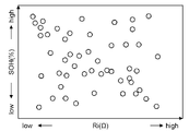
도 1은 전지의 내부 저항(Ri)과 열화 상태(SOH)의 변동을 예시하는 도면이다.
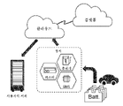
도 2는 전지 관리 장치의 용도를 예시하는 모식도이다.
도 3은 실시 형태 1에 관한 전지 관리 장치(100)의 구성예를 도시하는 도면이다.
도 4는 전지 관리 장치(100)의 다른 구성예를 도시하는 도면이다.
도 5는 검지부(130)가 전지(200)와 접속되어 있는 경우에 있어서의 구성예를 도시한다.
도 6은 연산부(120)가 Ri와 SOH를 계산하는 수순을 설명하는 흐름도이다.
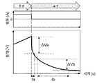
도 7은 방전 후의 휴지 기간에 있어서 전지(200)가 출력하는 전류와 전압의 경시 변화를 나타내는 그래프이다.
도 8은 충전 후의 휴지 기간에 있어서 전지(200)가 출력하는 전류와 전압의 경시 변화를 나타내는 그래프이다.
도 9는 관계 테이블(141)의 구성과 데이터예를 도시하는 도면이다.
도 10은 실시 형태 2에 있어서의 관계 테이블(141)의 구성예를 도시하는 도면이다.1 is a diagram illustrating variations in internal resistance (Ri) and deterioration state (SOH) of a battery.
2 is a schematic diagram illustrating the use of the battery management device.
3 is a diagram showing a configuration example of the
4 is a diagram showing another configuration example of the
5 shows a configuration example in the case where the
6 is a flowchart illustrating a procedure in which the
FIG. 7 is a graph showing changes over time in current and voltage output from the
8 is a graph showing changes in current and voltage output from the
Fig. 9 is a diagram showing the structure of the relationship table 141 and an example of data.
Fig. 10 is a diagram showing a configuration example of the relationship table 141 in the second embodiment.
<실시 형태 1><
도 1은 전지의 내부 저항(Ri)과 열화 상태(SOH)의 변동을 예시하는 도면이다. Ri와 SOH에 따라서, 적절한 사용 방법이나 용도 등이 다른 경우가 있다. 따라서 Ri와 SOH를 측정하는 것은, 전지의 운용 관리에 있어서 중요하다.1 is a diagram illustrating variations in internal resistance (Ri) and deterioration state (SOH) of a battery. Depending on Ri and SOH, appropriate methods of use and applications may differ. Therefore, measuring Ri and SOH is important in battery operation management.
도 2는 본 발명에 관한 전지 관리 장치의 용도를 예시하는 모식도이다. 충방전할 필요가 있는 전지(예를 들어 전지 셀, 전지 모듈, 전지 팩 등)는, 다양한 장치에 접속된다. 예를 들어 테스터, BMS(전지 관리 시스템), 충전기 등이다. 전지는 이들 장치에 접속되어 있을 때, 충전 동작/방전 동작/휴지 상태 중 어느 것이 된다. Ri와 SOH를 계산하는 알고리즘을 어디에서 실시하는지에 따라서, Ri와 SOH는 예를 들어 상기 장치 상에서 계산할 수도 있고, 클라우드 서버 상 등의 네트워크를 통해 접속된 컴퓨터 상에서 계산할 수도 있다. 전지가 접속된 장치 상에서 계산하는 이점은, 전지 상태(전지가 출력하는 전압, 전지가 출력하는 전류, 전지의 온도 등)를 고빈도로 취득할 수 있는 것이다.2 is a schematic diagram illustrating the use of the battery management device according to the present invention. Batteries that need to be charged and discharged (for example, battery cells, battery modules, battery packs, etc.) are connected to various devices. For example, a tester, BMS (Battery Management System), charger, etc. When the battery is connected to these devices, it is in any of charging operation / discharging operation / idle state. Depending on where the algorithm for calculating Ri and SOH is implemented, Ri and SOH may be calculated, for example, on the device or on a computer connected via a network, such as on a cloud server. An advantage of calculating on a device connected to a battery is that the battery state (voltage output by the battery, current output by the battery, temperature of the battery, etc.) can be acquired at high frequency.
클라우드 시스템 상에서 계산한 Ri나 SOH는, 유저가 소지하는 컴퓨터에 송신할 수도 있다. 유저 컴퓨터는 이 데이터를, 예를 들어 인벤토리 관리 등의 특정 용도에 제공할 수 있다. 클라우드 시스템 상에서 계산한 Ri나 SOH는, 클라우드 플랫폼 사업자의 데이터베이스에 저장하고, 다른 용도를 위해 사용할 수 있다. 예를 들어 전기 자동차의 교환 경로의 최적화, 에너지 관리 등이다.Ri and SOH calculated on the cloud system can also be transmitted to a computer possessed by the user. The user computer may provide this data for a specific purpose, such as inventory management, for example. Ri or SOH calculated on the cloud system can be stored in the database of the cloud platform operator and used for other purposes. For example, optimization of exchange routes for electric vehicles, energy management, etc.
도 3은 본 발명의 실시 형태 1에 관한 전지 관리 장치(100)의 구성예를 도시하는 도면이다. 도 3에 있어서, 전지 관리 장치(100)는, 전지(200)와 접속되어, 전지(200)로부터 전력 공급을 받는 장치이며, 도 2에 있어서의 테스터 등에 상당한다. 전지 관리 장치(100)는, 통신부(110), 연산부(120), 검지부(130), 기억부(140)를 구비한다.3 is a diagram showing a configuration example of a
검지부(130)는, 전지(200)가 출력하는 전압의 검출값 V, 전지(200)가 출력하는 전류의 검출값 I를 취득한다. 또한 옵션으로서, 전지(200)의 온도의 검출값 T를 취득해도 된다. 이들 검출값은, 전지(200) 자신이 검출하여 검지부(130)로 통지해도 되고 검지부(130)가 검출해도 된다. 검지부(130)의 상세는 후술한다.The
연산부(120)는, 검지부(130)가 취득한 검출값을 사용하여, 전지(200)의 Ri와 SOH를 추정한다. 추정 수순에 대해서는 후술한다. 통신부(110)는, 연산부(120)가 추정한 R과 SOH를, 전지 관리 장치(100)의 외부로 송신한다. 예를 들어 클라우드 시스템이 구비하는 메모리에 대하여 이들을 송신할 수 있다. 기억부(140)는, 후술하는 데이터 테이블을 저장한다.The
도 4는 전지 관리 장치(100)의 다른 구성예를 도시하는 도면이다. 전지 관리 장치(100)는, 반드시 전지(200)와 직접적으로 접속하여 전력 공급을 받는 장치는 아니어도 되고, 도 3에 기재된 통신부(110) 및 검지부(130)가 포함되어 있지 않은 형태를 나타내는 것이다. 도 4에 있어서 전지 관리 장치(100)는, 전지(200)의 전압 V, 전류 I, 온도 T를 통신부(110)로부터 취득한다. 구체적으로는, 전지 관리 장치(100)가 구비하는 검지부(150)는 이들 검출값을 예를 들어 네트워크 경유로 수취하고, 연산부(120)는 이들 검출값을 사용하여 Ri와 SOH를 계산한다.4 is a diagram showing another configuration example of the
도 5는 검지부(130)가 전지(200)와 접속되어 있는 경우에 있어서의 구성예를 도시한다. 검지부(130)는, 전지 관리 장치(100)의 일부로서 구성해도 되고, 전지 관리 장치(100)와는 다른 모듈로서 구성해도 된다. 검지부(130)는, 전지(200)의 충방전 동작 시에 있어서의 전압 V, 온도 T, 전류 I를 취득하기 위해, 전압 센서(131), 온도 센서(132), 전류 센서(133)를 구비한다.5 shows a configuration example in the case where the
전압 센서(131)는, 전지(200)의 양단 전압(전지(200)가 출력하는 전압)을 측정한다. 온도 센서(132)는, 예를 들어 전지(200)가 구비하는 열전대와 접속되고, 이것을 통해 전지(200)의 온도를 측정한다. 전류 센서(133)는, 전지(200)의 일단과 접속되어, 전지(200)가 출력하는 전류를 측정한다. 온도 센서(132)는 옵션이며, 반드시 구비하고 있지는 않아도 된다.The
도 6은 연산부(120)가 Ri와 SOH를 계산하는 수순을 설명하는 흐름도이다. 연산부(120)는, 예를 들어 전지 관리 장치(100)가 기동하였을 때, 본 흐름도를 개시하도록 지시되었을 때, 소정 주기마다 등의 적당한 타이밍에, 본 흐름도를 개시한다. 이하 도 6의 각 스텝을 설명한다.6 is a flowchart illustrating a procedure in which the
(도 6: 스텝 S601)(Fig. 6: Step S601)
연산부(120)는, 충전 후의 휴지 기간 또는 방전 후의 휴지 기간인지 여부를 판정한다. 현재가 휴지 기간이 아닌 경우에는 본 흐름도를 종료한다. 휴지 기간인 경우에는 S602로 진행한다. 예를 들어 방전 후의 휴지 기간인 것은, 전지(200)가 출력하는 전류가 부값(I<0)으로부터 제로를 향하여 변화되고 있는 것, (b) 부값으로부터 제로 근방의 값으로 변화되어 안정되어 있는 것(|I|<역치) 등에 의해 판정할 수 있다.The
(도 6: 스텝 S602)(Fig. 6: Step S602)
연산부(120)는, ΔVa와 ΔVb를 계산한다. ΔVa는, 휴지 기간이 종료된 이후의 제1 기산 시점으로부터 제1 기간 ta가 경과한 제1 시각까지에 있어서의, 전지(200)의 출력 전압의 변동분이다. ΔVb는, 제1 시각 이후의 제2 기산 시점으로부터 제2 기간 tb가 경과한 제2 시각까지에 있어서의, 전지(200)의 출력 전압 변동분이다. 이들 계산 수순에 대해서는 후술한다.The
(도 6: 스텝 S603)(Fig. 6: Step S603)
연산부(120)는, 하기 식 1과 식 2에 따라서, Ri와 SOH를 계산한다. fRi는, Ri를 ΔVa의 함수로서 정의한다. fRi는, 전지(200)의 온도에 의해 변동되는 파라미터(c_Ri_T)와, 전지(200)의 출력 전류에 의해 변동되는 파라미터(c_Ri_I)를 갖는다. fSOH는, SOH를 ΔVb의 함수로서 정의한다. fSOH는, 전지(200)의 온도에 의해 변동되는 파라미터(c_SOH_T)와, 전지(200)의 출력 전류에 의해 변동되는 파라미터(c_SOH_I)를 갖는다. 이들 파라미터는 관계 테이블(141)에 의해 정의되어 있다. 각 함수의 구체예와 관계 테이블(141)의 구체예에 대해서는 후술한다. fRi 및 fSOH는 예를 들어 로트마다의 실험 데이터를 기초로 형성되는 식이 된다.The
(도 6: 스텝 S604: 계산식)(Fig. 6: Step S604: Calculation formula)
Ri=fRi(ΔVa, c_Ri_T_1, c_Ri_T_2, ···, c_Ri_I_1, c_Ri_I_2, ···) (1)Ri=f Ri (ΔVa, c_Ri_T_1, c_Ri_T_2, ..., c_Ri_I_1, c_Ri_I_2, ...) (1)
SOH=fSOH(ΔVb, c_SOH_T_1, c_SOH_T_2, ···, c_SOH_I_1, c_SOH_I_2, ···) (2)SOH=f SOH (ΔVb, c_SOH_T_1, c_SOH_T_2, ..., c_SOH_I_1, c_SOH_I_2, ...) (2)
도 7은 방전 후의 휴지 기간에 있어서 전지(200)가 출력하는 전류와 전압의 경시 변화를 나타내는 그래프이다. S602에 있어서의 ΔVa는, 방전이 종료된 시점 또는 그것보다도 후의 제1 기산 시점으로부터 제1 기간 ta가 경과한 제1 시각까지에 있어서의, 전지(200)의 출력 전압의 변동분이다. 본 발명자는, 방전이 종료된 직후에 있어서의 출력 전압에 있어서, 전지(200)의 내부 저항에 의한 전압 변동이 잘 나타나 있음을 알아냈다. 즉 이 기간에 있어서의 출력 전압의 변동(ΔVa)은, Ri와의 사이의 상관이 강하다고 할 수 있다. 본 실시 형태 1에 있어서는 이것을 이용하여, ΔVa에 의해 Ri를 추정하는 것으로 하였다. ta의 개시 시각과 시간 길이 각각의 최적값은, 방전의 종료 시점 이후로부터 전압의 경시 변화 곡선에 있어서의 기울기 변화율의 최댓점까지의 구간에 기초하여 취득할 수 있다. 또한 상기 구간의 특정 시에는, 전지의 종류, 장치, 정밀도 등에 따라, 상기 구간의 양단 부근, 혹은 양단을 포함시킨 영역으로 하는 등, 적절히 바람직한 운용으로 하면 된다.FIG. 7 is a graph showing changes over time in current and voltage output from the
S602에 있어서의 ΔVb는, 기간 ta가 경과한 시점 또는 그 이후의 제2 기산 시점으로부터 제2 기간 tb가 경과한 제2 시각까지에 있어서의, 전지(200)의 출력 전압의 변동분이다. 방전 종료 직후에 있어서의 ΔVa가 Ri와의 사이에서 상관을 갖고 있는 것에 반해, 그것보다도 후의 출력 전압이 완만하게 변동되는 기간은, SOH와의 사이에서 상관을 갖고 있음을, 본 발명자는 알아냈다. 본 실시 형태 1에 있어서는 이것을 이용하여, ΔVb에 의해 SOH를 추정하는 것으로 하였다. tb의 개시 시각과 시간 길이 각각의 최적값은, 방전의 종료 시점 이후의 전압의 경시 변화 곡선에 있어서의 기울기 변화율의 최댓점으로부터 전압의 경시 변화 곡선의 기울기 변화가 일정하게 점근할 때까지의 구간에 기초하여 취득할 수 있다. 또한 상기 구간의 특정 시에는, 전지의 종류, 장치, 정밀도 등에 따라, 상기 구간의 양단 부근, 혹은 양단을 포함시킨 영역으로 하는 등, 적절히 바람직한 운용으로 하면 된다.ΔVb in S602 is the amount of change in the output voltage of the
ta의 개시 시각은, 반드시 방전 종료 시각과 동일하지는 않아도 되지만, 방전 종료 시각과 근접하고 있는 것이 바람직하다. tb의 개시 시각은, 반드시 ta의 종료 시각과 동일하지는 않아도 된다. 어느 경우라도, ta와 tb는, ta<tb라고 하는 관계가 있다. ΔVa의 크기와 ΔVb의 크기에 대해서는, ΔVa의 쪽이 큰 경우도 있을 수 있고, ΔVb의 쪽이 큰 경우도 있을 수 있다. 또한, 여기에서는 ta<tb로 하였지만, 전지의 종류, 장치, 정밀도 등에 따라, ta>tb, 혹은 ta=tb의 경우도 있을 수 있기 때문에, 적절히 바람직한 관계로 하면 된다.The start time of ta is not necessarily the same as the discharge end time, but is preferably close to the discharge end time. The start time of tb is not necessarily the same as the end time of ta. In either case, ta and tb have a relationship of ta<tb. Regarding the magnitudes of ΔVa and ΔVb, there may be cases where ΔVa is larger, and there may be cases where ΔVb is larger. In addition, although ta < tb is set here, depending on the type of battery, device, precision, etc., there may be cases where ta > tb or ta = tb, so a suitably preferable relationship may be employed.
ta와 tb의 합계가 예를 들어 수초 정도여도, Ri와 SOH를 고정밀도로 추정할 수 있음을, 본 발명자에 의한 실험 결과로부터 알 수 있었다. 따라서 본 실시 형태 1에 의하면, 휴지 기간에 있어서 빠르게 Ri와 SOH를 모두 추정할 수 있다.It was found from the experimental results by the present inventors that even when the sum of ta and tb is, for example, several seconds, Ri and SOH can be estimated with high accuracy. Therefore, according to the first embodiment, both Ri and SOH can be quickly estimated in the idle period.
도 8은 충전 후의 휴지 기간에 있어서 전지(200)가 출력하는 전류와 전압의 경시 변화를 나타내는 그래프이다. S602에 있어서의 ΔVa는, 방전 대신에, 충전이 종료된 시점 또는 그것보다도 후의 제1 기산 시점으로부터 제1 기간 ta가 경과한 제1 시각까지에 있어서의, 전지(200)의 출력 전압의 변동분이어도 된다. 이 경우, S602에 있어서의 ΔVb는, 기간 ta가 경과한 시점 또는 그 이후의 제2 기산 시점으로부터 제2 기간 tb가 경과한 제2 시각까지에 있어서의, 전지(200)의 출력 전압의 변동분이 된다. 충전 후의 휴지 기간에 있어서도, ΔVa는 Ri와의 사이에서 상관을 갖고, ΔVb는 SOH와의 사이에서 상관을 갖고 있음을, 본 발명자는 알아냈다. 따라서 본 실시 형태 1에 있어서, S602에 있어서의 ΔVa와 ΔVb는, 충방전 어느 것의 후에 있어서 취득해도 된다.8 is a graph showing changes in current and voltage output from the
도 9는 관계 테이블(141)의 구성과 데이터예를 도시하는 도면이다. 관계 테이블(141)은, 식 1과 식 2에 있어서의 각 파라미터를 정의하는 데이터 테이블이다. c_Ri_I와 c_SOH_I는 전지(200)의 출력 전류에 의해 변동되므로, 출력 전류값마다 정의되어 있다. c_Ri_T와 c_SOH_T는 전지(200)의 온도에 의해 변동되므로, 온도마다 정의되어 있다. 이들 파라미터는, 방전 후의 휴지 기간과 충전 후의 휴지 기간 사이에서 다른 특성을 갖는 경우가 있으므로, 관계 테이블(141)은 이들 기간마다 각 파라미터를 정의하고 있다.Fig. 9 is a diagram showing the structure of the relationship table 141 and an example of data. The relationship table 141 is a data table defining each parameter in
fRi가 ΔVa의 1차 함수인 경우, Ri는 예를 들어 하기 식 3에 의해 나타낼 수 있다. Ri의 기울기는 온도에 의해 영향을 받고, 절편은 전류에 의해 영향을 받기 때문이다. 이 경우, c_Ri_T와 c_Ri_I는 각각 1개이다.When f Ri is a linear function of ΔVa, Ri can be represented by Equation 3 below, for example. This is because the slope of Ri is affected by temperature and the intercept is affected by current. In this case, c_Ri_T and c_Ri_I are each one.
Ri=c_Ri_T_1×ΔVa+c_Ri_I_1 (3)Ri=c_Ri_T_1×ΔVa+c_Ri_I_1 (3)
fSOH가 ΔVb의 1차 함수인 경우, SOH는 예를 들어 하기 식 4에 의해 나타낼 수 있다. SOH의 기울기는 온도에 의해 영향을 받고, 절편은 전류에 의해 영향을 받기 때문이다. 이 경우, c_SOH_T와 c_SOH_I는 각각 1개이다.When f SOH is a linear function of ΔVb, SOH can be represented by Equation 4 below, for example. This is because the slope of SOH is affected by temperature and the intercept is affected by current. In this case, c_SOH_T and c_SOH_I are each one.
SOH=c_SOH_T_1×ΔVb+c_SOH_I_1 (4)SOH=c_SOH_T_1×ΔVb+c_SOH_I_1 (4)
<실시 형태 1: 정리><Embodiment 1: Summary>
본 실시 형태 1에 관한 전지 관리 장치(100)는, 방전 종료 후의 휴지 기간 또는 충전 종료 후의 휴지 기간에 있어서, 기간 ta에 있어서의 전압 변동 ΔVa를 사용하여 Ri를 추정하고, 기간 tb에 있어서의 전압 변동 ΔVb를 사용하여 SOH를 추정한다. 이에 의해, 종래보다도 단시간에 Ri와 SOH를 모두 추정할 수 있다.In the
본 실시 형태 1에 관한 전지 관리 장치(100)에 있어서, 관계 테이블(141)은, Ri와 ΔVa 사이의 관계를 나타내는 함수 fRi를 정의하는 내부 저항 파라미터를 기술한다. 내부 저항 파라미터는, 전지(200)의 출력 전류에 의해 변동되는 c_Ri_I와, 전지(200)의 온도에 의해 변동되는 c_Ri_T를 포함한다. 이에 의해, 함수 fRi가 전지(200)의 온도나 전지(200)의 출력 전류에 의해 변동되는 경우라도, Ri를 정확하게 추정할 수 있다. 함수 fSOH를 정의하는 열화 상태 파라미터에 대해서도 마찬가지이다.In the
본 실시 형태 1에 관한 전지 관리 장치(100)에 있어서, 관계 테이블(141)은, 충전 후의 휴지 기간과 방전 후의 휴지 기간 각각에 대하여, 내부 저항 파라미터와 열화 상태 파라미터를 기술한다. 이에 의해, 충전 후의 휴지 기간과 방전 후의 휴지 기간 사이에서 함수(즉 전지(200)의 특성)가 다른 경우라도, Ri와 SOH를 정확하게 추정할 수 있다.In the
<실시 형태 2><
도 10은 본 발명의 실시 형태 2에 있어서의 관계 테이블(141)의 구성예를 도시하는 도면이다. 실시 형태 1에 있어서의 관계 테이블(141)은, 충전 후의 휴지 기간과 방전 후의 휴지 기간 각각에 대하여, 파라미터를 정의하고 있는 것을 설명하였다. 관계 테이블(141)은 이것에 더하여, 전지(200)의 제조 로트 번호마다, 이들 파라미터를 정의해도 된다. Ri와 ΔVa 사이의 상관 관계나, SOH와 ΔVb 사이의 상관 관계는, 제조 로트마다 다른 경우가 있기 때문이다. 따라서 도 10에 있어서는, 제조 로트 번호마다 1개의 데이터 테이블을 마련한 예를 나타냈다. 연산부(120)는, 전지(200)의 제조 로트 번호에 대응하는 데이터 테이블로부터, 각 파라미터를 취득한다.Fig. 10 is a diagram showing an example of the configuration of the relationship table 141 in
<본 발명의 변형예에 대하여><About Modifications of the Present Invention>
본 발명은, 전술한 실시 형태에 한정되는 것은 아니고, 다양한 변형예가 포함된다. 예를 들어, 상기한 실시 형태는 본 발명을 이해하기 쉽게 설명하기 위해 상세하게 설명한 것이며, 반드시 설명한 모든 구성을 구비하는 것에 한정되는 것은 아니다. 또한, 어떤 실시 형태의 구성의 일부를 다른 실시 형태의 구성으로 치환하는 것이 가능하고, 또한, 어떤 실시 형태의 구성에 다른 실시 형태의 구성을 추가하는 것도 가능하다. 또한, 각 실시 형태의 구성의 일부에 대하여, 다른 구성의 추가·삭제·치환을 하는 것이 가능하다.The present invention is not limited to the above-described embodiment, and various modified examples are included. For example, the embodiments described above have been described in detail in order to easily understand the present invention, and are not necessarily limited to those having all the described configurations. In addition, it is possible to replace part of the configuration of one embodiment with the configuration of another embodiment, and it is also possible to add the configuration of another embodiment to the configuration of one embodiment. In addition, it is possible to add/delete/replace a part of the structure of each embodiment with another structure.
이상의 실시 형태에 있어서, 방전 후의 휴지 기간 또는 충전 후의 휴지 기간 중에서 ΔVa와 ΔVb를 취득하는 것을 설명하였다. 이때의 방전 또는 충전은, 반드시 완전 방전(전지(200)의 잔류 용량이 0)이나 완전 충전(전지(200)를 만충전함)은 아니어도 된다. 즉 방전 동작이나 충전 동작을 종료한 후의 기간이면 된다.In the above embodiment, it has been described that ΔVa and ΔVb are acquired during the rest period after discharging or during the rest period after charging. The discharge or charge at this time may not necessarily be complete discharge (the remaining capacity of the
이상의 실시 형태에 있어서, 방전 후의 휴지 기간 또는 충전 후의 휴지 기간 중에서 ΔVa와 ΔVb를 취득하는 것은, 방전 종료 직후에 있어서는 전지(200)의 출력 전류가 급준하게 상승하고, 충전 종료 직후에 있어서는 전지(200)의 출력 전류가 급준하게 하강하는 것을 상정한 것이다. 예를 들어 구형파상으로 전류가 상승 또는 하강하는 것을 상정하고 있다. 이것은, 출력 전류가 구형파임으로써, 출력 전류의 다양한 주파수 성분에 대한 전지(200)의 전압 응답이 얻어진다고 생각되기 때문이다. 따라서 방전 후의 휴지 기간 또는 충전 후의 휴지 기간에 있어서, 전지(200)의 출력 전류가 구형파상으로 변동되는 것이 바람직하다. 단 엄밀한 구형파가 아니더라도, 구형파에 근사하는 전류 파형이면 된다.In the above embodiment, acquiring ΔVa and ΔVb during the rest period after discharge or during the rest period after charge causes the output current of the
이상의 실시 형태에 있어서, 함수 fRi와 fSOH의 일례로서 1차 함수를 예시하였지만, 그 밖의 함수여도 된다. 예를 들어 2차 함수 이상의 다항 함수 등이어도 된다. 관계 테이블(141)은, 어느 경우라도, 그 함수를 정의하기 위한 계수 등의 파라미터를 기술하면 된다. 파라미터 중 전지(200)의 출력 전류에 의해 변동되는 것에 대해서는 전류값마다 정의하고, 전지(200)의 온도에 의해 변동되는 것에 대해서는 온도값마다 정의하면 된다.In the above embodiment, a linear function was exemplified as an example of the functions f Ri and f SOH , but other functions may be used. For example, a polynomial function higher than a quadratic function may be used. In any case, the relationship table 141 may describe parameters such as coefficients for defining the function. Among the parameters, parameters that vary by the output current of the
이상의 실시 형태에 있어서, 연산부(120)와 검지부(130)는, 이들 기능을 실장한 회로 디바이스 등의 하드웨어에 의해 구성할 수도 있고, 이들 기능을 실장한 소프트웨어를 CPU(Central Processing Unit) 등의 연산 장치가 실행함으로써 구성할 수도 있다.In the above embodiment, the
이상의 실시 형태에 있어서, 기억부(140)는, 반드시 연산부(120)와 동일한 장치 상에 배치할 필요는 없다. 즉, 연산부(120)가 관계 테이블(141)에 의해 정의되어 있는 정보를 취득하여 로컬 메모리 등의 기억 장치에 저장할 수 있으면, 관계 테이블(141) 그 자체는 연산부(120)와는 다른 장치 상에 배치해도 된다.In the above embodiment, the
100: 전지 관리 장치
110: 통신부
120: 연산부
130: 검지부
140: 기억부
141: 관계 테이블
200: 전지100: battery management device
110: communication department
120: calculation unit
130: detection unit
140: storage unit
141: relationship table
200: battery
Claims (12)
상기 전지가 출력하는 전압의 검출값과 상기 전지가 출력하는 전류의 검출값을 취득하는 검지부,
상기 전압의 경시 변화를 나타내는 차분을 사용하여 상기 전지의 내부 저항과 상기 전지의 열화 상태를 추정하는 연산부
를 구비하고,
상기 연산부는, 상기 차분으로서, 상기 전지가 충전 또는 방전을 종료한 종료 시점 이후의 제1 기산 시점에 있어서의 상기 전압과, 상기 제1 기산 시점으로부터 제1 기간이 경과한 제1 시점에 있어서의 상기 전압 사이의 제1 차분을 취득하고,
상기 연산부는, 상기 차분으로서, 상기 제1 시점 이후의 제2 기산 시점에 있어서의 상기 전압과, 상기 제2 기산 시점으로부터 제2 기간이 경과한 제2 시점에 있어서의 상기 전압 사이의 제2 차분을 취득하고,
상기 연산부는, 상기 제1 차분과 상기 내부 저항 사이의 관계를 기술함과 함께 상기 제2 차분과 상기 열화 상태 사이의 관계를 기술한 관계 데이터를 취득하고,
상기 연산부는, 상기 제1 차분을 사용하여 상기 관계 데이터를 참조함으로써 상기 내부 저항을 추정하고,
상기 연산부는, 상기 제2 차분을 사용하여 상기 관계 데이터를 참조함으로써 상기 열화 상태를 추정하는 것을 특징으로 하는 전지 관리 장치.A battery management device that manages the state of a battery,
a detecting unit for obtaining a detected value of a voltage output from the battery and a detected value of a current output from the battery;
A calculation unit for estimating the internal resistance of the battery and the deterioration state of the battery using the difference representing the change in voltage over time
to provide,
The calculation unit calculates, as the difference, the voltage at a first calculated time point after the end point at which the battery is charged or discharged, and a first time point at which a first period has elapsed from the first calculated time point. obtaining a first difference between the voltages;
The calculation unit, as the difference, a second difference between the voltage at a second calculated time point after the first time point and the voltage at a second time point at which a second period has elapsed from the second calculated time point. to acquire,
The calculation unit obtains relational data describing a relationship between the second difference and the deterioration state as well as describing a relationship between the first difference and the internal resistance,
The calculation unit estimates the internal resistance by referring to the relational data using the first difference,
The battery management device according to claim 1 , wherein the calculation unit estimates the deterioration state by referring to the relationship data using the second difference.
상기 제1 기간은, 충전 또는 방전의 종료 시점 이후의 전압 변화 곡선에 있어서, 충전 또는 방전의 종료 시점 이후로부터 상기 전압 변화 곡선의 기울기 변화율의 최댓점까지의 구간으로 하고,
상기 제2 기간은, 상기 기울기 변화율의 최댓점으로부터 상기 전압 변화 곡선의 기울기 변화가 일정에 점근할 때까지의 구간으로 하는 것을 특징으로 하는 전지 관리 장치.According to claim 1,
The first period, in the voltage change curve after the end of charge or discharge, is a section from after the end of charge or discharge to the maximum point of the change rate of the slope of the voltage change curve,
The battery management device according to claim 1 , wherein the second period is an interval from a maximum point of the slope change rate until a slope change of the voltage change curve approaches a constant.
상기 관계 데이터는, 상기 내부 저항과 상기 제1 차분 사이의 관계를 나타내는 내부 저항 함수를 정의하는 내부 저항 파라미터를 기술하고 있고,
상기 내부 저항 파라미터는,
상기 전지의 온도에 의해 변동되는 내부 저항_온도 파라미터,
상기 전류에 의해 변동되는 내부 저항_전류 파라미터
를 포함하고,
상기 관계 데이터는, 상기 전지의 온도의 값마다 상기 내부 저항_온도 파라미터를 기술함과 함께, 상기 전류의 값마다 상기 내부 저항_전류 파라미터를 기술하고 있고,
상기 연산부는, 상기 관계 데이터로부터 취득한 상기 내부 저항 파라미터를 사용하여, 상기 내부 저항을 계산하는 것을 특징으로 하는 전지 관리 장치.According to claim 1,
The relationship data describes an internal resistance parameter defining an internal resistance function representing a relationship between the internal resistance and the first difference,
The internal resistance parameter is,
An internal resistance_temperature parameter varied by the temperature of the battery;
Internal resistance_current parameter varied by the current
including,
The relationship data describes the internal resistance_temperature parameter for each temperature value of the battery and the internal resistance_current parameter for each current value,
The battery management device according to claim 1 , wherein the calculation unit calculates the internal resistance using the internal resistance parameter acquired from the relational data.
상기 관계 데이터는, 상기 열화 상태와 상기 제2 차분 사이의 관계를 나타내는 열화 상태 함수를 정의하는 열화 상태 파라미터를 기술하고 있고,
상기 열화 상태 파라미터는,
상기 전지의 온도에 의해 변동되는 열화 상태_온도 파라미터,
상기 전류에 의해 변동되는 열화 상태_전류 파라미터
를 포함하고,
상기 관계 데이터는, 상기 전지의 온도의 값마다 상기 열화 상태_온도 파라미터를 기술함과 함께, 상기 전류의 값마다 상기 열화 상태_전류 파라미터를 기술하고 있고,
상기 연산부는, 상기 관계 데이터로부터 취득한 상기 열화 상태 파라미터를 사용하여, 상기 열화 상태를 계산하는 것을 특징으로 하는 전지 관리 장치.According to claim 1,
The relationship data describes a degradation state parameter defining a degradation state function representing a relationship between the degradation state and the second difference,
The deterioration state parameter,
A deterioration state_temperature parameter varied by the temperature of the battery;
Deterioration state_current parameter varied by the current
including,
The relationship data describes the deterioration state_temperature parameter for each temperature value of the battery and the degradation state_current parameter for each current value,
The battery management device according to claim 1 , wherein the calculation unit calculates the deterioration state using the deterioration state parameter obtained from the relation data.
상기 내부 저항 함수는, 상기 내부 저항과 상기 제1 차분 사이의 관계를 상기 제1 차분의 1차 함수에 의해 나타내는 함수이며,
상기 내부 저항_온도 파라미터는, 상기 1차 함수의 기울기를 상기 전지의 온도의 값마다 정의하고 있고,
상기 내부 저항_전류 파라미터는, 상기 1차 함수의 절편을 상기 전류의 값마다 정의하고 있고,
상기 연산부는, 상기 전지의 온도의 측정값을 사용하여 상기 관계 데이터를 참조함으로써, 상기 1차 함수의 기울기를 취득하고,
상기 연산부는, 상기 전류의 측정값을 사용하여 상기 관계 데이터를 참조함으로써, 상기 1차 함수의 절편을 취득하고,
상기 연산부는, 상기 관계 데이터로부터 취득한 상기 기울기와 상기 관계 데이터로부터 취득한 상기 절편을 사용하여, 상기 내부 저항을 계산하는 것을 특징으로 하는 전지 관리 장치.According to claim 3,
The internal resistance function is a function representing a relationship between the internal resistance and the first difference by a linear function of the first difference,
The internal resistance_temperature parameter defines a slope of the linear function for each temperature value of the battery,
The internal resistance_current parameter defines an intercept of the linear function for each value of the current,
The calculation unit obtains the slope of the linear function by referring to the relational data using the measured value of the temperature of the battery;
The calculation unit acquires an intercept of the linear function by referring to the relational data using the measured value of the current;
The battery management device according to claim 1 , wherein the calculation unit calculates the internal resistance using the slope obtained from the relationship data and the intercept obtained from the relationship data.
상기 열화 상태 함수는, 상기 열화 상태와 상기 제2 차분 사이의 관계를 상기 제2 차분의 1차 함수에 의해 나타내는 함수이며,
상기 열화 상태_온도 파라미터는, 상기 1차 함수의 기울기를 상기 전지의 온도의 값마다 정의하고 있고,
상기 열화 상태_전류 파라미터는, 상기 1차 함수의 절편을 상기 전류의 값마다 정의하고 있고,
상기 연산부는, 상기 전지의 온도의 측정값을 사용하여 상기 관계 데이터를 참조함으로써, 상기 1차 함수의 기울기를 취득하고,
상기 연산부는, 상기 전류의 측정값을 사용하여 상기 관계 데이터를 참조함으로써, 상기 1차 함수의 절편을 취득하고,
상기 연산부는, 상기 관계 데이터로부터 취득한 상기 기울기와 상기 관계 데이터로부터 취득한 상기 절편을 사용하여, 상기 열화 상태를 계산하는 것을 특징으로 하는 전지 관리 장치.According to claim 4,
The degradation state function is a function representing a relationship between the degradation state and the second difference by a linear function of the second difference,
The deterioration state_temperature parameter defines a slope of the linear function for each temperature value of the battery,
The deterioration state_current parameter defines an intercept of the linear function for each value of the current,
The calculation unit obtains the slope of the linear function by referring to the relational data using the measured value of the temperature of the battery;
The calculation unit obtains an intercept of the linear function by referring to the relational data using the measured value of the current;
The battery management device according to claim 1 , wherein the calculation unit calculates the deterioration state using the slope obtained from the relationship data and the intercept obtained from the relationship data.
상기 관계 데이터는, 상기 전지가 충전 종료된 후의 제1 휴지 기간과, 상기 전지가 방전 완료된 후의 제2 휴지 기간의 각각에 대하여, 상기 내부 저항 파라미터를 기술하고 있고,
상기 관계 데이터는, 상기 제1 휴지 기간에 있어서의 상기 내부 저항 파라미터를 정의하는 충전 후 파라미터를 기술하고 있고,
상기 관계 데이터는, 상기 제2 휴지 기간에 있어서의 상기 내부 저항 파라미터를 정의하는 방전 후 파라미터를 기술하고 있고,
상기 연산부는, 상기 제1 휴지 기간에 있어서는 상기 관계 데이터로부터 상기 충전 후 파라미터를 취득하고,
상기 연산부는, 상기 제2 휴지 기간에 있어서는 상기 관계 데이터로부터 상기 방전 후 파라미터를 취득하는 것을 특징으로 하는 전지 관리 장치.According to claim 3,
The relationship data describes the internal resistance parameter for each of a first idle period after the battery is charged and a second idle period after the battery is discharged,
The relationship data describes a post-charge parameter defining the internal resistance parameter in the first idle period,
The relationship data describes a post-discharge parameter defining the internal resistance parameter in the second idle period,
The calculation unit obtains the post-charge parameter from the relation data in the first idle period;
The battery management device according to claim 1 , wherein the calculation unit acquires the post-discharge parameter from the relation data in the second idle period.
상기 관계 데이터는, 상기 전지가 충전 종료된 후의 제1 휴지 기간과, 상기 전지가 방전 완료된 후의 제2 휴지 기간의 각각에 대하여, 상기 열화 상태 파라미터를 기술하고 있고,
상기 관계 데이터는, 상기 제1 휴지 기간에 있어서의 상기 열화 상태 파라미터를 정의하는 충전 후 파라미터를 기술하고 있고,
상기 관계 데이터는, 상기 제2 휴지 기간에 있어서의 상기 열화 상태 파라미터를 정의하는 방전 후 파라미터를 기술하고 있고,
상기 연산부는, 상기 제1 휴지 기간에 있어서는 상기 관계 데이터로부터 상기 충전 후 파라미터를 취득하고,
상기 연산부는, 상기 제2 휴지 기간에 있어서는 상기 관계 데이터로부터 상기 방전 후 파라미터를 취득하는 것을 특징으로 하는 전지 관리 장치.According to claim 4,
The relationship data describes the deterioration state parameter for each of a first idle period after the battery is charged and a second idle period after the battery is discharged;
The relationship data describes a post-charge parameter defining the deterioration state parameter in the first idle period,
The relationship data describes a post-discharge parameter defining the deterioration state parameter in the second idle period,
The calculation unit obtains the post-charge parameter from the relation data in the first idle period;
The battery management device according to claim 1 , wherein the calculation unit acquires the post-discharge parameter from the relation data in the second idle period.
상기 관계 데이터는, 상기 전지의 제조 로트 번호마다 상기 내부 저항 파라미터를 기술하고 있고,
상기 연산부는, 상기 전지의 제조 로트 번호를 사용하여 상기 관계 데이터를 참조함으로써, 상기 내부 저항 파라미터를 취득하는 것을 특징으로 하는 전지 관리 장치.According to claim 3,
The relationship data describes the internal resistance parameter for each manufacturing lot number of the battery,
The battery management device according to claim 1 , wherein the calculation unit acquires the internal resistance parameter by referring to the relationship data using the production lot number of the battery.
상기 관계 데이터는, 상기 전지의 제조 로트 번호마다 상기 열화 상태 파라미터를 기술하고 있고,
상기 연산부는, 상기 전지의 제조 로트 번호를 사용하여 상기 관계 데이터를 참조함으로써, 상기 열화 상태 파라미터를 취득하는 것을 특징으로 하는 전지 관리 장치.According to claim 4,
The relationship data describes the deterioration state parameter for each manufacturing lot number of the battery,
The battery management device according to claim 1 , wherein the calculation unit obtains the deterioration state parameter by referring to the relationship data using the production lot number of the battery.
상기 전지는, 방전을 종료하면 상기 전류가 구형파상으로 상승하고, 또는, 충전을 종료하면 상기 전류가 구형파상으로 하강하도록 구성되어 있고,
상기 연산부는, 상기 구형파상의 상승 또는 하강에 의해 발생하는 상기 전압의 변동분을, 상기 제1 차분 중 적어도 일부로서 취득하는 것을 특징으로 하는 전지 관리 장치.According to claim 1,
The battery is configured so that the current rises in a square wave shape when discharging is completed, or the current decreases in a square wave shape when charging is completed,
The battery management device according to claim 1 , wherein the calculation unit acquires, as at least a part of the first difference, a variation of the voltage caused by a rise or fall of the square wave.
상기 전지가 출력하는 전압의 검출값과 상기 전지가 출력하는 전류의 검출값을 취득하는 스텝,
상기 전압의 경시 변화를 나타내는 차분을 사용하여 상기 전지의 내부 저항과 상기 전지의 열화 상태를 추정하는 스텝
을 갖고,
상기 추정하는 스텝에 있어서는, 상기 차분으로서, 상기 전지가 충전 또는 방전을 종료한 종료 시점 이후의 제1 기산 시점에 있어서의 상기 전압과, 상기 제1 기산 시점으로부터 제1 기간이 경과한 제1 시점에 있어서의 상기 전압 사이의 제1 차분을 취득하고,
상기 추정하는 스텝에 있어서는, 상기 차분으로서, 상기 제1 시점 이후의 제2 기산 시점에 있어서의 상기 전압과, 상기 제2 기산 시점으로부터 제2 기간이 경과한 제2 시점에 있어서의 상기 전압 사이의 제2 차분을 취득하고,
상기 추정하는 스텝에 있어서는, 상기 제1 차분과 상기 내부 저항 사이의 관계를 기술함과 함께 상기 제2 차분과 상기 열화 상태 사이의 관계를 기술한 관계 데이터를 취득하고,
상기 추정하는 스텝에 있어서는, 상기 제1 차분을 사용하여 상기 관계 데이터를 참조함으로써 상기 내부 저항을 추정하고,
상기 추정하는 스텝에 있어서는, 상기 제2 차분을 사용하여 상기 관계 데이터를 참조함으로써 상기 열화 상태를 추정하는 것을 특징으로 하는 전지 관리 방법.A battery management method for managing the state of a battery,
Acquiring a detected value of a voltage output by the battery and a detected value of a current output by the battery;
Estimating the internal resistance of the battery and the deterioration state of the battery using the difference representing the change in voltage with time
have
In the estimating step, as the difference, the voltage at a first calculated point in time after the end of charging or discharging of the battery and a first point in time at which a first period has elapsed from the first calculated point in time Obtaining a first difference between the voltages in
In the estimating step, as the difference, between the voltage at a second calculated time point after the first time point and the voltage at a second time point at which a second period has elapsed from the second calculated time point obtaining a second difference;
In the estimating step, relationship data describing a relationship between the first difference and the internal resistance and a relationship between the second difference and the state of deterioration are acquired,
In the estimating step, the internal resistance is estimated by referring to the relationship data using the first difference,
In the estimating step, the deterioration state is estimated by referring to the relationship data using the second difference.
Applications Claiming Priority (1)
| Application Number | Priority Date | Filing Date | Title |
|---|---|---|---|
| PCT/JP2020/028961 WO2022024235A1 (en) | 2020-07-29 | 2020-07-29 | Battery management device, battery management method |
Publications (1)
| Publication Number | Publication Date |
|---|---|
| KR20230012022A true KR20230012022A (en) | 2023-01-25 |
Family
ID=80035462
Family Applications (1)
| Application Number | Title | Priority Date | Filing Date |
|---|---|---|---|
| KR1020227044015A KR20230012022A (en) | 2020-07-29 | 2020-07-29 | Battery management device, battery management method |
Country Status (7)
| Country | Link |
|---|---|
| US (1) | US20230349981A1 (en) |
| EP (1) | EP4191732A4 (en) |
| JP (1) | JP7390490B2 (en) |
| KR (1) | KR20230012022A (en) |
| CN (1) | CN115917341A (en) |
| TW (2) | TWI785665B (en) |
| WO (1) | WO2022024235A1 (en) |
Families Citing this family (5)
| Publication number | Priority date | Publication date | Assignee | Title |
|---|---|---|---|---|
| JP2022170227A (en) * | 2021-04-28 | 2022-11-10 | 株式会社日立ハイテク | Battery state estimation device and power system |
| JP2023119877A (en) * | 2022-02-17 | 2023-08-29 | 株式会社日立製作所 | Battery management device and battery management program |
| JP2023136212A (en) * | 2022-03-16 | 2023-09-29 | 株式会社日立ハイテク | Battery state estimation device, battery system, and battery state estimation method |
| CN114966452B (en) * | 2022-08-01 | 2022-10-25 | 华为电动技术有限公司 | Battery state determination method and related device |
| JP2024029593A (en) * | 2022-08-22 | 2024-03-06 | 株式会社日立製作所 | Battery management device, battery management method |
Citations (3)
| Publication number | Priority date | Publication date | Assignee | Title |
|---|---|---|---|---|
| JP2010175484A (en) | 2009-01-31 | 2010-08-12 | Calsonic Kansei Corp | Method for estimating internal resistance component of battery and method for estimating charge capacity |
| JP2013088148A (en) | 2011-10-13 | 2013-05-13 | Waseda Univ | Battery system and battery evaluation method |
| JP2017129401A (en) | 2016-01-19 | 2017-07-27 | 日立化成株式会社 | Battery state estimation method and device |
Family Cites Families (17)
| Publication number | Priority date | Publication date | Assignee | Title |
|---|---|---|---|---|
| JP2974157B2 (en) * | 1990-10-22 | 1999-11-08 | 株式会社ユアサコーポレーション | Remaining life judgment method of lead storage battery |
| WO2007032382A1 (en) * | 2005-09-16 | 2007-03-22 | The Furukawa Electric Co., Ltd | Secondary cell degradation judgment method, secondary cell degradation judgment device, and power supply system |
| JP4215083B2 (en) | 2006-09-04 | 2009-01-28 | トヨタ自動車株式会社 | Cam cap and oil passage connection structure |
| JP4954791B2 (en) * | 2007-05-24 | 2012-06-20 | 株式会社Kri | Voltage prediction method for power storage devices |
| JP5323396B2 (en) * | 2008-05-29 | 2013-10-23 | 株式会社Kri | Input / output characteristic evaluation system and charge / discharge test apparatus incorporating the same |
| JP2014025738A (en) * | 2012-07-25 | 2014-02-06 | Sanyo Electric Co Ltd | Residual capacity estimation device |
| JP6595009B2 (en) * | 2016-01-29 | 2019-10-23 | 日立オートモティブシステムズ株式会社 | Battery state estimation device |
| US11415630B2 (en) * | 2016-02-29 | 2022-08-16 | University Of Hawaii | Methods and apparatus for updating a fuel gauge and estimating state of health of an energy storage cell |
| TWI581542B (en) * | 2016-03-01 | 2017-05-01 | 財團法人工業技術研究院 | Battery management system and battery system using the same |
| JP2017175705A (en) * | 2016-03-22 | 2017-09-28 | Ntn株式会社 | Secondary battery deterioration suppression device and individual deterioration suppression device |
| JP6655801B2 (en) * | 2016-03-31 | 2020-02-26 | パナソニックIpマネジメント株式会社 | Lithium ion secondary battery life estimation device |
| WO2017199629A1 (en) * | 2016-05-18 | 2017-11-23 | 日立オートモティブシステムズ株式会社 | Battery control device |
| JP6443577B2 (en) * | 2017-06-02 | 2018-12-26 | 株式会社Gsユアサ | Management device, power storage module, management method, and computer program |
| TWI741245B (en) * | 2017-12-29 | 2021-10-01 | 英屬開曼群島商睿能創意公司 | Systems and methods for managing energy storage devices positioned in device exchange station |
| JP7101506B2 (en) * | 2018-03-26 | 2022-07-15 | 日立Astemo株式会社 | Battery deterioration judgment device |
| JP7322529B2 (en) * | 2018-06-14 | 2023-08-08 | 株式会社Gsユアサ | Estimation device, power storage device, estimation method, and computer program |
| JP2020003218A (en) * | 2018-06-25 | 2020-01-09 | 日立化成株式会社 | Deterioration determining method for lead battery |
-
2020
- 2020-07-29 US US18/010,090 patent/US20230349981A1/en active Pending
- 2020-07-29 CN CN202080102254.8A patent/CN115917341A/en active Pending
- 2020-07-29 JP JP2022539847A patent/JP7390490B2/en active Active
- 2020-07-29 EP EP20947705.8A patent/EP4191732A4/en active Pending
- 2020-07-29 KR KR1020227044015A patent/KR20230012022A/en active Search and Examination
- 2020-07-29 WO PCT/JP2020/028961 patent/WO2022024235A1/en active Application Filing
-
2021
- 2021-07-05 TW TW110124617A patent/TWI785665B/en active
- 2021-07-05 TW TW111140342A patent/TWI818777B/en active
Patent Citations (3)
| Publication number | Priority date | Publication date | Assignee | Title |
|---|---|---|---|---|
| JP2010175484A (en) | 2009-01-31 | 2010-08-12 | Calsonic Kansei Corp | Method for estimating internal resistance component of battery and method for estimating charge capacity |
| JP2013088148A (en) | 2011-10-13 | 2013-05-13 | Waseda Univ | Battery system and battery evaluation method |
| JP2017129401A (en) | 2016-01-19 | 2017-07-27 | 日立化成株式会社 | Battery state estimation method and device |
Also Published As
| Publication number | Publication date |
|---|---|
| CN115917341A (en) | 2023-04-04 |
| US20230349981A1 (en) | 2023-11-02 |
| TW202309544A (en) | 2023-03-01 |
| EP4191732A1 (en) | 2023-06-07 |
| WO2022024235A1 (en) | 2022-02-03 |
| TWI785665B (en) | 2022-12-01 |
| EP4191732A4 (en) | 2024-04-17 |
| TWI818777B (en) | 2023-10-11 |
| JPWO2022024235A1 (en) | 2022-02-03 |
| JP7390490B2 (en) | 2023-12-01 |
| TW202204926A (en) | 2022-02-01 |
Similar Documents
| Publication | Publication Date | Title |
|---|---|---|
| KR20230012022A (en) | Battery management device, battery management method | |
| Lee et al. | Temperature-compensated model for lithium-ion polymer batteries with extended Kalman filter state-of-charge estimation for an implantable charger | |
| US10175302B2 (en) | Power system and state of charge estimation | |
| US10355321B2 (en) | Method and device for detecting states of battery and battery pack | |
| CN106461732B (en) | Method for estimating state of health of battery | |
| US10845417B2 (en) | Battery state estimation device, battery control device, battery system, battery state estimation method | |
| US20190036356A1 (en) | Method and System for Estimating Battery Open Cell Voltage, State of Charge, and State of Health During Operation of the Battery | |
| TWI422849B (en) | Battery capacity estimation by dcir | |
| US8775106B2 (en) | Method for determining a parameter of at least one accumulator of a battery | |
| JP6113920B2 (en) | Method for determining the capacity of a battery cell | |
| US20140232411A1 (en) | System and method for battery monitoring | |
| TW201531725A (en) | Method and apparatus for detecting internal resistance of a battery | |
| CN101535827A (en) | Apparatus and method for determination of the state-of-charge of a battery when the battery is not in equilibrium | |
| JP2014211427A (en) | Battery management system and driving method thereof | |
| KR20140139322A (en) | Battery management system and driving method thereof | |
| CN104698385A (en) | Cell state calculation apparatus and cell state calculation method | |
| CN109143097A (en) | It is a kind of meter and temperature and cycle-index lithium ion battery SOC estimation method | |
| WO2022230335A1 (en) | Battery state estimation device and power system | |
| JP2016065844A (en) | Battery system control apparatus and control method of battery system | |
| Yao et al. | A simple internal resistance estimation method based on open circuit voltage test under different temperature conditions | |
| CN113030751B (en) | Battery state of charge (SOC) estimation method, device, management system and vehicle | |
| JP2023032183A (en) | Correction method, computer program, correction device, and power storage device | |
| Beckers et al. | Round-Trip Energy Efficiency and Energy-Efficiency Fade Estimation for Battery Passport | |
| TWI802317B (en) | Battery management device, battery management method | |
| TWI509521B (en) | Method for modeling equivalent circuit of li-ion battery |
Legal Events
| Date | Code | Title | Description |
|---|---|---|---|
| A201 | Request for examination |