KR20220159971A - Optical measuring device and optical measuring method - Google Patents
Optical measuring device and optical measuring method Download PDFInfo
- Publication number
- KR20220159971A KR20220159971A KR1020227031968A KR20227031968A KR20220159971A KR 20220159971 A KR20220159971 A KR 20220159971A KR 1020227031968 A KR1020227031968 A KR 1020227031968A KR 20227031968 A KR20227031968 A KR 20227031968A KR 20220159971 A KR20220159971 A KR 20220159971A
- Authority
- KR
- South Korea
- Prior art keywords
- light
- signal
- irradiation
- calibration
- detection
- Prior art date
Links
- 230000003287 optical effect Effects 0.000 title claims abstract description 278
- 238000000034 method Methods 0.000 title claims abstract description 240
- 238000005259 measurement Methods 0.000 claims abstract description 288
- 238000001514 detection method Methods 0.000 claims abstract description 259
- 230000008569 process Effects 0.000 claims abstract description 219
- 238000012545 processing Methods 0.000 claims abstract description 145
- 230000001678 irradiating effect Effects 0.000 claims description 34
- 238000000691 measurement method Methods 0.000 claims description 18
- 239000000758 substrate Substances 0.000 claims description 9
- 230000005284 excitation Effects 0.000 abstract description 112
- 238000010586 diagram Methods 0.000 description 42
- 238000003317 immunochromatography Methods 0.000 description 27
- 239000011521 glass Substances 0.000 description 23
- 238000006243 chemical reaction Methods 0.000 description 20
- 239000003153 chemical reaction reagent Substances 0.000 description 20
- 238000012360 testing method Methods 0.000 description 19
- 230000003321 amplification Effects 0.000 description 14
- 238000003199 nucleic acid amplification method Methods 0.000 description 14
- 230000000737 periodic effect Effects 0.000 description 14
- 230000000694 effects Effects 0.000 description 11
- 239000000126 substance Substances 0.000 description 11
- 239000000427 antigen Substances 0.000 description 6
- 102000036639 antigens Human genes 0.000 description 6
- 108091007433 antigens Proteins 0.000 description 6
- 239000000463 material Substances 0.000 description 6
- 229910052693 Europium Inorganic materials 0.000 description 5
- OGPBJKLSAFTDLK-UHFFFAOYSA-N europium atom Chemical compound [Eu] OGPBJKLSAFTDLK-UHFFFAOYSA-N 0.000 description 5
- 230000010354 integration Effects 0.000 description 4
- 239000012528 membrane Substances 0.000 description 4
- 238000004519 manufacturing process Methods 0.000 description 3
- 230000004044 response Effects 0.000 description 3
- 230000009471 action Effects 0.000 description 2
- 229910052782 aluminium Inorganic materials 0.000 description 2
- XAGFODPZIPBFFR-UHFFFAOYSA-N aluminium Chemical compound [Al] XAGFODPZIPBFFR-UHFFFAOYSA-N 0.000 description 2
- 230000015572 biosynthetic process Effects 0.000 description 2
- 230000008859 change Effects 0.000 description 2
- 230000003111 delayed effect Effects 0.000 description 2
- 238000001914 filtration Methods 0.000 description 2
- 229910052751 metal Inorganic materials 0.000 description 2
- 239000002184 metal Substances 0.000 description 2
- 239000004065 semiconductor Substances 0.000 description 2
- 238000007493 shaping process Methods 0.000 description 2
- 238000003786 synthesis reaction Methods 0.000 description 2
- 241000712461 unidentified influenza virus Species 0.000 description 2
- 238000011144 upstream manufacturing Methods 0.000 description 2
- 238000004458 analytical method Methods 0.000 description 1
- 230000002238 attenuated effect Effects 0.000 description 1
- 239000000919 ceramic Substances 0.000 description 1
- 238000004891 communication Methods 0.000 description 1
- 238000005520 cutting process Methods 0.000 description 1
- 238000009792 diffusion process Methods 0.000 description 1
- 238000009826 distribution Methods 0.000 description 1
- 230000008030 elimination Effects 0.000 description 1
- 238000003379 elimination reaction Methods 0.000 description 1
- 238000000605 extraction Methods 0.000 description 1
- 238000003018 immunoassay Methods 0.000 description 1
- 230000006872 improvement Effects 0.000 description 1
- 239000004615 ingredient Substances 0.000 description 1
- 238000011068 loading method Methods 0.000 description 1
- 230000007246 mechanism Effects 0.000 description 1
- 238000002360 preparation method Methods 0.000 description 1
- 238000003672 processing method Methods 0.000 description 1
- 239000011347 resin Substances 0.000 description 1
- 229920005989 resin Polymers 0.000 description 1
- 229920006395 saturated elastomer Polymers 0.000 description 1
- 230000002194 synthesizing effect Effects 0.000 description 1
Images


Classifications
-
- G—PHYSICS
- G01—MEASURING; TESTING
- G01N—INVESTIGATING OR ANALYSING MATERIALS BY DETERMINING THEIR CHEMICAL OR PHYSICAL PROPERTIES
- G01N21/00—Investigating or analysing materials by the use of optical means, i.e. using sub-millimetre waves, infrared, visible or ultraviolet light
- G01N21/17—Systems in which incident light is modified in accordance with the properties of the material investigated
- G01N21/25—Colour; Spectral properties, i.e. comparison of effect of material on the light at two or more different wavelengths or wavelength bands
- G01N21/27—Colour; Spectral properties, i.e. comparison of effect of material on the light at two or more different wavelengths or wavelength bands using photo-electric detection ; circuits for computing concentration
- G01N21/274—Calibration, base line adjustment, drift correction
-
- G—PHYSICS
- G01—MEASURING; TESTING
- G01N—INVESTIGATING OR ANALYSING MATERIALS BY DETERMINING THEIR CHEMICAL OR PHYSICAL PROPERTIES
- G01N21/00—Investigating or analysing materials by the use of optical means, i.e. using sub-millimetre waves, infrared, visible or ultraviolet light
- G01N21/62—Systems in which the material investigated is excited whereby it emits light or causes a change in wavelength of the incident light
- G01N21/63—Systems in which the material investigated is excited whereby it emits light or causes a change in wavelength of the incident light optically excited
- G01N21/64—Fluorescence; Phosphorescence
- G01N21/645—Specially adapted constructive features of fluorimeters
-
- G—PHYSICS
- G01—MEASURING; TESTING
- G01N—INVESTIGATING OR ANALYSING MATERIALS BY DETERMINING THEIR CHEMICAL OR PHYSICAL PROPERTIES
- G01N21/00—Investigating or analysing materials by the use of optical means, i.e. using sub-millimetre waves, infrared, visible or ultraviolet light
- G01N21/17—Systems in which incident light is modified in accordance with the properties of the material investigated
- G01N21/47—Scattering, i.e. diffuse reflection
- G01N21/4738—Diffuse reflection, e.g. also for testing fluids, fibrous materials
-
- G—PHYSICS
- G01—MEASURING; TESTING
- G01N—INVESTIGATING OR ANALYSING MATERIALS BY DETERMINING THEIR CHEMICAL OR PHYSICAL PROPERTIES
- G01N21/00—Investigating or analysing materials by the use of optical means, i.e. using sub-millimetre waves, infrared, visible or ultraviolet light
- G01N21/62—Systems in which the material investigated is excited whereby it emits light or causes a change in wavelength of the incident light
- G01N21/63—Systems in which the material investigated is excited whereby it emits light or causes a change in wavelength of the incident light optically excited
- G01N21/64—Fluorescence; Phosphorescence
- G01N21/6408—Fluorescence; Phosphorescence with measurement of decay time, time resolved fluorescence
-
- G—PHYSICS
- G01—MEASURING; TESTING
- G01N—INVESTIGATING OR ANALYSING MATERIALS BY DETERMINING THEIR CHEMICAL OR PHYSICAL PROPERTIES
- G01N21/00—Investigating or analysing materials by the use of optical means, i.e. using sub-millimetre waves, infrared, visible or ultraviolet light
- G01N21/84—Systems specially adapted for particular applications
- G01N21/8483—Investigating reagent band
-
- G—PHYSICS
- G01—MEASURING; TESTING
- G01N—INVESTIGATING OR ANALYSING MATERIALS BY DETERMINING THEIR CHEMICAL OR PHYSICAL PROPERTIES
- G01N21/00—Investigating or analysing materials by the use of optical means, i.e. using sub-millimetre waves, infrared, visible or ultraviolet light
- G01N21/17—Systems in which incident light is modified in accordance with the properties of the material investigated
- G01N21/47—Scattering, i.e. diffuse reflection
- G01N2021/473—Compensating for unwanted scatter, e.g. reliefs, marks
-
- G—PHYSICS
- G01—MEASURING; TESTING
- G01N—INVESTIGATING OR ANALYSING MATERIALS BY DETERMINING THEIR CHEMICAL OR PHYSICAL PROPERTIES
- G01N21/00—Investigating or analysing materials by the use of optical means, i.e. using sub-millimetre waves, infrared, visible or ultraviolet light
- G01N21/62—Systems in which the material investigated is excited whereby it emits light or causes a change in wavelength of the incident light
- G01N21/63—Systems in which the material investigated is excited whereby it emits light or causes a change in wavelength of the incident light optically excited
- G01N21/64—Fluorescence; Phosphorescence
- G01N21/645—Specially adapted constructive features of fluorimeters
- G01N2021/6463—Optics
-
- G—PHYSICS
- G01—MEASURING; TESTING
- G01N—INVESTIGATING OR ANALYSING MATERIALS BY DETERMINING THEIR CHEMICAL OR PHYSICAL PROPERTIES
- G01N21/00—Investigating or analysing materials by the use of optical means, i.e. using sub-millimetre waves, infrared, visible or ultraviolet light
- G01N21/75—Systems in which material is subjected to a chemical reaction, the progress or the result of the reaction being investigated
- G01N21/77—Systems in which material is subjected to a chemical reaction, the progress or the result of the reaction being investigated by observing the effect on a chemical indicator
- G01N2021/7756—Sensor type
- G01N2021/7759—Dipstick; Test strip
-
- G—PHYSICS
- G01—MEASURING; TESTING
- G01N—INVESTIGATING OR ANALYSING MATERIALS BY DETERMINING THEIR CHEMICAL OR PHYSICAL PROPERTIES
- G01N21/00—Investigating or analysing materials by the use of optical means, i.e. using sub-millimetre waves, infrared, visible or ultraviolet light
- G01N21/75—Systems in which material is subjected to a chemical reaction, the progress or the result of the reaction being investigated
- G01N21/77—Systems in which material is subjected to a chemical reaction, the progress or the result of the reaction being investigated by observing the effect on a chemical indicator
- G01N2021/7769—Measurement method of reaction-produced change in sensor
- G01N2021/7786—Fluorescence
-
- G—PHYSICS
- G01—MEASURING; TESTING
- G01N—INVESTIGATING OR ANALYSING MATERIALS BY DETERMINING THEIR CHEMICAL OR PHYSICAL PROPERTIES
- G01N2201/00—Features of devices classified in G01N21/00
- G01N2201/12—Circuits of general importance; Signal processing
- G01N2201/127—Calibration; base line adjustment; drift compensation
Abstract
광학 측정 장치에서는, 제1 처리에 있어서, 레퍼런스 부재에 여기광을 조사하여, 레퍼런스 부재로부터의 여기광의 산란광을 포함하는 캘리브레이션 처리용 광을 검출광으로서 검출하고, 캘리브레이션 처리용 광에 따른 캘리브레이션 신호를 검출 신호로 하여, 제2 처리에 있어서의 검출 신호로부터 산란광에 따른 신호 성분을 제거하기 위한 캘리브레이션 처리를 실시한다. 또, 광학 측정 장치에서는, 제2 처리에 있어서, 시료에 여기광을 조사하여, 시료로부터 생기는 형광, 및 여기광이 조사된 시료로부터의 산란광을 포함하는 측정 대상광을 검출광으로서 검출하고, 측정 신호로부터, 제1 처리에 있어서의 캘리브레이션 처리의 실시 결과에 있어서의 산란광에 따른 신호 성분을 제거한다. In the optical measuring device, in the first process, the reference member is irradiated with excitation light, calibration processing light including scattered light of the excitation light from the reference member is detected as detection light, and a calibration signal according to the calibration processing light is obtained. As the detection signal, a calibration process for removing a signal component associated with scattered light from the detection signal in the second process is performed. Further, in the optical measurement device, in the second process, the sample is irradiated with excitation light, and measurement target light including fluorescence generated from the sample and scattered light from the sample to which the excitation light is irradiated is detected as detection light, and measurement is performed. From the signal, a signal component associated with scattered light in the result of performing the calibration process in the first process is removed.
Description
본 발명의 일 양태는 시료의 광학 특성을 측정하기 위한 광학 측정 장치 및 광학 측정 방법에 관한 것이다. One aspect of the present invention relates to an optical measurement device and an optical measurement method for measuring optical characteristics of a sample.
특허 문헌 1에는 기판 상에 놓인 형광 샘플에 대해서 여기광을 조사하고, 형광을 측정했을 때 포함되는 형광 노이즈 성분(기판으로부터의 형광 성분)을 제거할 수 있도록, 감쇠 신호를 생성하여 제하는 기술이 개시되어 있다. 구체적으로는, 특허 문헌 1에서는, 기판의 형광과 동일한 위상의 감쇠 신호를 생성하여, 측정한 형광 신호로부터 그 감쇠 신호를 제함으로써, 형광 노이즈 성분을 제거하고 있다. In
상술한 것처럼, 특허 문헌 1에서는, 여기광을 시료에 조사함으로써 생기는 형광으로부터, 시료의 측정 대상부 이외로부터 생기는 형광 노이즈 성분이 제거되어 있다. 여기서, 시료에 광을 조사하고, 시료로부터의 광을 검출했을 때 포함되는 노이즈 성분에는, 시료(조사된 것)로부터 생기는 광(예를 들면 형광)에 기인하는 것뿐만이 아니라, 조사광(예를 들면 여기광) 자체(예를 들면 산란광)가 노이즈 성분이 되는 일도 생각할 수 있다. 특허 문헌 1의 기술에서는, 조사광 자체가 노이즈 성분이 되었을 경우를 고려하고 있지 않아, 해당 노이즈 성분을 제거할 수 없다. As described above, in
한편, 본 발명자 등은 검출광에 포함되는 형광 및 산란광(조사광 자체에 기인하는 광)의 위상의 차이에 주목하여, 검출광으로부터, 조사광과 동일한 위상을 가지는 신호 성분인 산란광의 신호 성분을 제거함으로써, 조사광 자체에 기인하는 노이즈 성분을 제거하는 광학 측정 장치를 찾아냈다. 이러한 광학 측정 장치에 있어서는, 예를 들면, 사전에 캘리브레이션(calibration) 처리가 실시된다. 캘리브레이션 처리에서는, 시료에 있어서의 형광이 생기기 어려운 부분에 조사광을 조사함으로써 캘리브레이션 처리용 광(이상적으로는 산란광만을 포함하는 광)을 검출하고, 그 캘리브레이션 처리용 광에 따른 캘리브레이션 신호에 기초하여, 검출 신호로부터, 대략 산란광 성분에 따른 신호 성분만을 제거할 수 있다. On the other hand, the inventors of the present invention pay attention to the difference in phase between fluorescence and scattered light (light resulting from the irradiation light itself) included in the detection light, and derive a signal component of the scattered light, which is a signal component having the same phase as the irradiation light, from the detection light. An optical measuring device was found that removes the noise component caused by the irradiation light itself by removing it. In such an optical measurement device, a calibration process is performed in advance, for example. In the calibration process, light for calibration process (ideally, light containing only scattered light) is detected by irradiating irradiation light to a portion of the sample where fluorescence is unlikely to occur, and based on the calibration signal according to the light for calibration process, From the detection signal, only signal components approximately corresponding to the scattered light components can be removed.
여기서, 캘리브레이션 처리에서는, 시료(예를 들면 측정을 실시하기 쉽도록 칩화된 것, 이하 실제 샘플)에 있어서의, 형광을 발생시키기 어려운 부분(예를 들면 실제 샘플에 있어서 형광 물질이 적다고 판단되는 영역)에 조사광을 조사함으로써, 대체로 산란광만을 포함한 캘리브레이션 처리용 광을 검출하는 것을 생각할 수 있다. 그렇지만, 실제 샘플에 조사광을 조사하여 캘리브레이션 처리용 광을 검출하는 방법에 있어서는, 광 검출기에서 검출되는 캘리브레이션 처리용 광으로부터 형광을 완전하게 제거하는 것이 곤란하여, 캘리브레이션 신호 처리용 광에는 미량의 형광 성분이 포함되어 버린다. 이것에 의해, 산란광 성분에 더하여 및 미량의 형광 성분에 기초하여 캘리브레이션 처리가 행해지게 되어, 캘리브레이션 처리가 형광 성분의 영향을 받은 결과, 그 후의 형광 측정을 고정밀도로 행할 수 없을 우려가 있는 것을 알았다. Here, in the calibration process, in a sample (e.g., a chip for easy measurement, hereinafter, an actual sample), a portion in which fluorescence is difficult to generate (e.g., a portion in which the fluorescent material is judged to be small in the actual sample) It is conceivable to detect light for calibration processing, which generally includes only scattered light, by irradiating irradiation light to the area). However, in the method of detecting light for calibration processing by irradiating irradiation light to an actual sample, it is difficult to completely remove fluorescence from the light for calibration processing detected by the photodetector, so that a trace amount of fluorescence is present in the light for processing the calibration signal. Ingredients are included As a result, the calibration process is performed in addition to the scattered light component and based on a trace amount of the fluorescence component, and as a result of the calibration process being affected by the fluorescence component, it has been found that there is a possibility that the subsequent fluorescence measurement cannot be performed with high accuracy.
본 발명의 일 앙태는 상기 실정을 감안하여 이루어진 것으로, 조사광 자체에 기인하는 노이즈 성분을 제거하여, 형광 측정을 고정밀도로 행하는 것이 가능한 광학 측정 장치 및 광학 측정 방법을 제공하는 것을 목적으로 한다. One aspect of the present invention has been made in view of the above situation, and aims to provide an optical measurement device and an optical measurement method capable of performing fluorescence measurement with high accuracy by removing noise components caused by irradiation light itself.
본 발명의 일 양태에 따른 광학 측정 장치는, 측정 대상물의 광학 특성을 측정하는 광학 측정 장치로서, 조사 대상에 조사광을 조사하는 조사 광학계와, 조사광에 기인하는 검출광을 검출하는 광 검출부와, 검출광에 따른 검출 신호를 처리하는 신호 처리부를 구비하고, 제1 처리에서는, 조사 광학계가 측정 대상물과는 상이한 캘리브레이션 처리용의 레퍼런스 부재를 조사 대상으로 하여, 레퍼런스 부재에 조사광을 조사하고, 광 검출부가 조사광이 조사된 레퍼런스 부재로부터의 조사광의 산란광을 포함하는 캘리브레이션 처리용 광을 검출광으로서 검출하고, 신호 처리부가 캘리브레이션 처리용 광에 따른 캘리브레이션 신호를 검출 신호로 하고, 그 캘리브레이션 신호에 기초하여, 제2 처리에 있어서의 검출 신호로부터 산란광에 따른 신호 성분을 제거하기 위한 캘리브레이션 처리를 실시하고, 제2 처리에서는, 조사 광학계가 측정 대상물을 조사 대상으로 하여, 측정 대상물에 조사광을 조사하고, 광 검출부가 조사광이 조사된 측정 대상물로부터 생기는 형광, 및 조사광이 조사된 측정 대상물로부터의 산란광을 포함하는 측정 대상광을 검출광으로서 검출하고, 신호 처리부가 측정 대상광에 따른 측정 신호를 검출 신호로 하고, 측정 신호로부터, 제1 처리에 있어서의 캘리브레이션 처리에 있어서의 산란광에 따른 신호 성분을 제거한다. An optical measurement device according to one aspect of the present invention is an optical measurement device for measuring optical characteristics of a measurement object, comprising: an irradiation optical system for irradiating irradiation light onto an irradiation target; a photodetector for detecting detection light resulting from the irradiation light; , a signal processing unit for processing a detection signal according to the detection light, and in the first process, the irradiation optical system irradiates a reference member for calibration processing different from the measurement object as an irradiation target, and irradiates the reference member with irradiation light; An optical detection unit detects, as detection light, light for calibration processing including scattered light of irradiation light from a reference member irradiated with irradiation light, and a signal processing unit uses a calibration signal according to the calibration light as a detection signal, Based on this, a calibration process is performed to remove a signal component related to scattered light from the detection signal in the second process, and in the second process, the irradiation optical system sets the measurement target as an irradiation target and irradiates the measurement target with irradiation light. The light detection unit detects, as detection light, measurement target light including fluorescence generated from the measurement target irradiated with the irradiated light and scattered light from the measurement target irradiated with the irradiated light, and the signal processing unit detects a measurement signal according to the measurement target light. is a detection signal, and a signal component associated with scattered light in the calibration process in the first process is removed from the measurement signal.
본 발명의 일 양태에 따른 광학 측정 장치에서는, 캘리브레이션 처리와 관련된 제1 처리에 있어서, 측정 대상물과는 상이한 레퍼런스 부재에 조사광이 조사되어 산란광을 포함하는 캘리브레이션 처리용 광이 검출되고 있다. 그리고, 제2 처리에 있어서, 캘리브레이션 처리의 실시 결과에 기초하여, 측정 신호로부터 산란광에 따른 신호 성분을 적절히 제거함으로써, 조사광 자체에 기인하는 노이즈 성분을 제거하여, 형광 측정을 고정밀도로 행할 수 있다. 또, 측정 대상물과는 상이한, 캘리브레이션 처리용의 레퍼런스 부재가 이용됨으로써, 예를 들면 측정 대상물에 조사광을 조사하여 캘리브레이션 처리용 광을 검출하는 경우에 문제가 되는, 측정 대상물의 특성에 따른 캘리브레이션 처리의 결과의 편차가 생기지 않는다. 그 때문에, 형광 측정을 보다 고정밀도로 행할 수 있다. 이와 같이, 본 발명의 일 양태에 따른 광학 측정 장치에 의하면, 캘리브레이션 처리를 보다 적절히 행할 수 있어, 조사광 자체에 기인하는 노이즈 성분을 보다 적절히 제거하여, 형광 측정을 보다 고정밀도로 행할 수 있다. In the optical measurement device according to one aspect of the present invention, in the first process related to the calibration process, irradiation light is irradiated to a reference member different from the object to be measured, and calibration light including scattered light is detected. Then, in the second process, based on the result of the calibration process, signal components related to scattered light are appropriately removed from the measurement signal, thereby eliminating noise components caused by the irradiation light itself, and fluorescence measurement can be performed with high accuracy. . In addition, calibration processing according to the characteristics of the measurement object, which is a problem when a reference member for calibration processing that is different from the measurement object is used, for example, when the measurement object is irradiated with irradiation light and the calibration light is detected. There is no variation in the results of Therefore, fluorescence measurement can be performed with higher precision. In this way, according to the optical measuring device according to one aspect of the present invention, the calibration process can be performed more appropriately, the noise component caused by the irradiated light itself can be removed more appropriately, and the fluorescence measurement can be performed with higher precision.
레퍼런스 부재는 조사광을 반사하는 반사 부재를 포함하고 있어도 된다. 이러한 구성에 의하면, 검출광의 광량을 용이하게 크게 할 수 있다. The reference member may include a reflective member that reflects the irradiation light. According to this configuration, the amount of detection light can be easily increased.
반사 부재는 조사광의 조사에 의해 형광을 발생시키지 않는 것이 바람직하다. 이러한 구성에 의하면, 조사광의 조사에 의해서도, 반사 부재에 기인하는 형광이 발생하지 않기(혹은, 무시할 수 있는 정도밖에 형광을 발생시키지 않기) 때문에, 제2 처리에 있어서, 측정 신호로부터 산란광 성분에 따른 신호 성분만을 확실히 제거할 수 있다. It is preferable that the reflective member does not generate fluorescence when irradiated with irradiation light. According to this configuration, fluorescence due to the reflection member is not generated even when irradiated light is irradiated (or fluorescence is generated only to a negligible extent). Only signal components can be definitely removed.
반사 부재는 조사광을 확산하는 반사 확산체를 포함하고 있어도 된다. 이러한 구성에 의하면, 반사 확산체에 의해서 다양한 각도의 산란광을 용이하게 발생시킬 수 있어, 검출광의 광량을 보다 용이하게 크게 할 수 있다. The reflective member may include a reflective diffuser that diffuses the irradiated light. According to this structure, scattered light of various angles can be easily generated by the reflection diffuser, and the light quantity of the detection light can be more easily increased.
반사 부재는 조사광을 반사하는 반사 기재와, 반사 기재에 지지되고, 조사광을 확산하는 확산체를 포함하고 있어도 된다. 이러한 구성에 의하면, 반사 기재와 확산체의 협동에 의해서, 검출광의 광량을 보다 용이하게 크게 할 수 있다. The reflective member may include a reflective substrate that reflects the irradiated light, and a diffuser that is supported by the reflective substrate and diffuses the irradiated light. According to this configuration, the light quantity of the detection light can be more easily increased by cooperation of the reflective substrate and the diffuser.
반사 부재는 미러를 포함하고 있어도 된다. 이러한 구성에 의하면, 광 검출부에 대한 미러의 반사 각도를 조정함으로써, 검출광의 광량을 보다 용이하게 크게 할 수 있다. The reflecting member may contain a mirror. According to this configuration, the amount of detection light can be more easily increased by adjusting the reflection angle of the mirror with respect to the photodetector.
본 발명의 일 양태에 따른 광학 측정 장치는, 측정 대상물의 광학 특성을 측정하는 광학 측정 장치로서, 조사광을 조사하는 조사 광학계와, 조사광에 기인하는 검출광을 검출하는 제1 검출 광학계 및 제2 검출 광학계를 가지는 광 검출부와, 검출광에 따른 검출 신호를 처리하는 신호 처리부를 구비하고, 제1 처리에서는, 조사 광학계가 제1 검출 광학계에 조사광을 조사하고, 광 검출부의 제1 검출 광학계가 조사광인 캘리브레이션 처리용 광을 검출광으로서 검출하고, 신호 처리부가 캘리브레이션 처리용 광에 따른 캘리브레이션 신호를 검출 신호로 하고, 그 캘리브레이션 신호에 기초하여, 제2 처리에 있어서의 검출 신호로부터 산란광에 따른 신호 성분을 제거하기 위한 캘리브레이션 처리를 실시하고, 제2 처리에서는, 조사 광학계가 측정 대상물에 조사광을 조사하고, 광 검출부의 제2 검출 광학계가 조사광이 조사된 측정 대상물로부터 생기는 형광, 및 조사광이 조사된 측정 대상물로부터의 산란광을 포함하는 측정 대상광을 검출광으로서 검출하고, 신호 처리부가 측정 대상광에 따른 측정 신호를 검출 신호로 하고, 측정 신호로부터, 제1 처리에 있어서의 캘리브레이션 처리에 있어서의 산란광에 따른 신호 성분을 제거한다. An optical measurement device according to one aspect of the present invention is an optical measurement device for measuring optical characteristics of a measurement object, comprising: an irradiation optical system for irradiating irradiation light; a first detection optical system for detecting detection light resulting from the irradiation light; and A photodetection unit having two detection optical systems and a signal processing unit that processes a detection signal corresponding to the detection light. In a first process, the irradiation optical system irradiates the first detection optical system with irradiation light, and the first detection optical system of the photodetection unit is provided. detects light for calibration processing, which is irradiated light, as detection light; Calibration processing for removing signal components is performed, and in the second processing, the irradiation optical system irradiates the measurement object with irradiation light, and the second detection optical system of the photodetector unit detects fluorescence and irradiation generated from the measurement object to which the irradiation light is irradiated. The measurement target light including scattered light from the measurement target irradiated with light is detected as detection light, the signal processing unit sets a measurement signal according to the measurement target light as a detection signal, and calibration processing in the first process is performed from the measurement signal. The signal component according to the scattered light in is removed.
본 발명의 일 양태에 따른 광학 측정 장치에서는, 캘리브레이션 처리와 관련된 제1 처리에 있어서, 제1 검출 광학계에 대해서 직접 조사광이 조사되고, 그 조사광인 캘리브레이션 처리용 광이 검출되고 있다. 조사광은 산란광과 같은 위상을 가지는 광이다. 이 때문에, 제1 검출 광학계가 조사광을 캘리브레이션 처리용 광으로서 검출함으로써, 형광을 포함하지 않고 또한 산란광과 같은 위상의 광을 캘리브레이션 처리용 광으로서 적절히 검출하는 것이 가능해진다. 이것으로, 제2 처리에 있어서, 캘리브레이션 처리의 실시 결과에 기초하여, 측정 신호로부터 산란광에 따른 신호 성분을 적절히 제거함으로써, 조사광 자체에 기인하는 노이즈 성분을 제거하여, 형광 측정을 고정밀도로 행할 수 있다. 또, 측정 대상물에 조사광을 조사하지 않고 캘리브레이션 처리용 광이 검출되기 때문에, 예를 들면 측정 대상물에 조사광을 조사하여 캘리브레이션 처리용 광을 검출하는 경우에 문제가 되는, 측정 대상물의 특성에 따른 캘리브레이션 처리의 결과의 편차가 생기지 않는다. 그 때문에, 형광 측정을 보다 고정밀도로 행할 수 있다. 이와 같이, 본 발명의 일 양태에 따른 광학 측정 장치에 의하면, 캘리브레이션 처리를 보다 적절히 행할 수 있어, 조사광 자체에 기인하는 노이즈 성분을 보다 적절히 제거하여, 형광 측정을 보다 고정밀도로 행할 수 있다. In the optical measuring device according to one aspect of the present invention, in the first process related to the calibration process, the first detection optical system is directly irradiated with irradiated light, and the irradiated light, the calibration light, is detected. The irradiation light is light having the same phase as the scattered light. For this reason, when the first detection optical system detects the irradiated light as the calibration light, it becomes possible to appropriately detect light that does not contain fluorescence and has the same phase as the scattered light as the calibration light. With this, in the second process, based on the result of the calibration process, signal components related to scattered light are appropriately removed from the measurement signal, thereby eliminating noise components caused by the irradiation light itself, and fluorescence measurement can be performed with high accuracy. have. In addition, since the calibration light is detected without irradiating the measurement object with irradiation light, for example, depending on the characteristics of the measurement object, which is a problem in the case of detecting the calibration light by irradiating the measurement object with irradiation light. Variation in the result of the calibration process does not occur. Therefore, fluorescence measurement can be performed with higher precision. In this way, according to the optical measuring device according to one aspect of the present invention, the calibration process can be performed more appropriately, the noise component caused by the irradiated light itself can be removed more appropriately, and the fluorescence measurement can be performed with higher precision.
본 발명의 일 양태에 따른 광학 측정 장치는, 측정 대상물의 광학 특성을 측정하는 광학 측정 장치로서, 변조 신호에 따른 조사광을 조사하는 조사 광학계와, 조사광에 기인하는 검출광을 검출하는 광 검출부와, 신호 처리부를 구비하고, 제1 처리에서는, 신호 처리부가 조사 광학계로부터 조사된 조사광의 산란광이 검출광으로서 광 검출부에 검출될 때까지에 상당하는 지연에 따라 변조 신호의 위상을 변화시킨 캘리브레이션 신호를 생성하고, 그 캘리브레이션 신호에 기초하여, 제2 처리에 있어서의 검출 신호로부터 산란광에 따른 신호 성분을 제거하기 위한 캘리브레이션 처리를 실시하고, 제2 처리에서는, 조사 광학계가 측정 대상물에 조사광을 조사하고, 광 검출부가 조사광이 조사된 측정 대상물로부터 생기는 형광, 및 조사광이 조사된 측정 대상물로부터의 산란광을 포함하는 측정 대상광을 검출광으로서 검출하고, 신호 처리부가 측정 대상광에 따른 측정 신호를 검출 신호로 하고, 측정 신호로부터, 제1 처리에 있어서의 캘리브레이션 처리에 있어서의 산란광에 따른 신호 성분을 제거한다. An optical measurement device according to an aspect of the present invention is an optical measurement device for measuring optical characteristics of a measurement object, comprising: an irradiation optical system for irradiating irradiation light according to a modulated signal; and a photodetector for detecting detection light resulting from the irradiation light. and a signal processing unit, wherein in the first processing, the signal processing unit changes the phase of the modulation signal according to a delay until the scattered light of the irradiation light emitted from the irradiation optical system is detected by the photodetector as detection light, a calibration signal is generated, and based on the calibration signal, a calibration process for removing a signal component according to scattered light is performed from the detection signal in the second process, and in the second process, the irradiation optical system irradiates the measurement target with irradiated light The light detection unit detects, as detection light, measurement target light including fluorescence generated from the measurement target irradiated with the irradiated light and scattered light from the measurement target irradiated with the irradiated light, and the signal processing unit detects a measurement signal according to the measurement target light. is a detection signal, and a signal component associated with scattered light in the calibration process in the first process is removed from the measurement signal.
본 발명의 일 양태에 따른 광학 측정 장치에서는, 캘리브레이션 처리와 관련된 제1 처리에 있어서, 조사 광학계에 입력되는 변조 신호의 위상을 조사 광학계의 지연에 따라 변화시킨 캘리브레이션 신호가 생성된다. 이와 같이, 조사광과 관련된 변조 신호에 대해 조사 광학계의 지연에 따라 캘리브레이션 신호가 생성됨으로써, 캘리브레이션 처리용 광을 검출하는 일 없이, 실제로 산란광을 캘리브레이션 처리용 광으로서 검출했을 경우와 같은 캘리브레이션 신호(산란광과 같은 위상을 가지는 캘리브레이션 신호)를 얻을 수 있다. 즉, 이러한 구성에 의하면, 형광의 신호 성분을 포함하지 않는 산란광의 신호 성분만의 캘리브레이션 신호를 얻을 수 있다. 이것으로, 제2 처리에 있어서, 캘리브레이션 처리의 실시 결과에 기초하여, 측정 신호로부터 산란광에 따른 신호 성분을 적절히 제거함으로써, 조사광 자체에 기인하는 노이즈 성분을 제거하여, 형광 측정을 고정밀도로 행할 수 있다. 또, 측정 대상물에 조사광을 조사하지 않고 캘리브레이션 처리용 광이 검출되기 때문에, 예를 들면 측정 대상물에 조사광을 조사하여 캘리브레이션 처리용 광을 검출하는 경우에 문제가 되는, 측정 대상물의 특성에 따른 캘리브레이션 처리의 결과의 편차가 생기지 않는다. 그 때문에, 형광 측정을 보다 고정밀도로 행할 수 있다. 이와 같이, 본 발명의 일 양태에 따른 광학 측정 장치에 의하면, 캘리브레이션 처리를 보다 적절히 행할 수 있어, 조사광 자체에 기인하는 노이즈 성분을 보다 적절히 제거하여, 형광 측정을 보다 고정밀도로 행할 수 있다. In the optical measuring device according to one aspect of the present invention, in the first process related to the calibration process, a calibration signal in which a phase of a modulated signal input to the irradiation optical system is changed according to a delay of the irradiation optical system is generated. In this way, a calibration signal is generated according to the delay of the irradiation optical system for the modulated signal related to the irradiation light, so that the same calibration signal as when actually detecting the scattered light as the calibration light (scattered light A calibration signal having the same phase as That is, according to this structure, it is possible to obtain a calibration signal of only the signal component of scattered light that does not include the signal component of fluorescence. With this, in the second process, based on the result of the calibration process, signal components related to scattered light are appropriately removed from the measurement signal, thereby eliminating noise components caused by the irradiation light itself, and fluorescence measurement can be performed with high accuracy. have. In addition, since the calibration light is detected without irradiating the measurement object with irradiation light, for example, depending on the characteristics of the measurement object, which is a problem in the case of detecting the calibration light by irradiating the measurement object with irradiation light. Variation in the result of the calibration process does not occur. Therefore, fluorescence measurement can be performed with higher precision. In this way, according to the optical measuring device according to one aspect of the present invention, the calibration process can be performed more appropriately, the noise component caused by the irradiated light itself can be removed more appropriately, and the fluorescence measurement can be performed with higher precision.
제1 처리에서는, 신호 처리부가 조사 광학계로부터 조사된 조사광의 산란광이 검출광으로서 광 검출부에 검출되는 경우의 진폭에 따라 캘리브레이션 신호의 진폭을 설정해도 된다. 이것에 의해, 산란광을 캘리브레이션 처리용 광으로서 실제로 검출하는 경우에 보다 근사시킨 캘리브레이션 신호를 얻을 수 있다. In the first process, the signal processing unit may set the amplitude of the calibration signal according to the amplitude when scattered light of irradiation light emitted from the irradiation optical system is detected by the photodetector unit as detection light. This makes it possible to obtain a more approximate calibration signal in the case of actually detecting scattered light as light for calibration processing.
본 발명의 일 양태에 따른 광학 측정 방법은, 측정 대상물의 광학 특성을 측정하는 광학 측정 방법으로서, 측정 대상물과는 상이한 캘리브레이션 처리용의 레퍼런스 부재에 조사광을 조사하는 것과, 조사광이 조사된 레퍼런스 부재로부터의 조사광의 산란광을 포함하는 캘리브레이션 처리용 광을 검출하는 것과, 캘리브레이션 처리용 광에 따른 캘리브레이션 신호에 기초하여, 측정 신호로부터 산란광에 따른 신호 성분을 제거하기 위한 캘리브레이션 처리를 실시하는 것을 포함하는 제1 처리와, 측정 대상물에 조사광을 조사하는 것과, 조사광이 조사된 측정 대상물로부터 생기는 형광, 및 조사광이 조사된 측정 대상물로부터의 산란광을 포함하는 측정 대상광을 검출하는 것과, 측정 대상광에 따른 측정 신호로부터, 제1 처리에 있어서의 캘리브레이션 처리에 있어서의 산란광에 따른 신호 성분을 제거하는 것을 포함하는 제2 처리를 실행한다. An optical measurement method according to one aspect of the present invention is an optical measurement method for measuring the optical characteristics of a measurement object, comprising irradiating irradiated light to a reference member for calibration processing different from the measurement object, and a reference to which the irradiated light is irradiated. Detecting light for calibration processing including scattered light of the irradiation light from the member, and performing calibration processing for removing a signal component according to the scattered light from the measurement signal based on the calibration signal according to the light for calibration processing First processing, irradiating the measurement object with irradiated light, detecting measurement object light including fluorescence generated from the measurement object irradiated with the irradiated light and scattered light from the measurement object irradiated with the irradiated light, and From the measurement signal according to the light, a second process including removing a signal component corresponding to the scattered light in the calibration process in the first process is executed.
본 발명의 일 양태에 따른 광학 측정 방법은, 측정 대상물의 광학 특성을 측정하는 광학 측정 방법으로서, 조사광을 조사하는 것과, 조사광인 캘리브레이션 처리용 광을 검출하는 것과, 캘리브레이션 처리용 광에 따른 캘리브레이션 신호에 기초하여, 측정 신호로부터 산란광에 따른 신호 성분을 제거하기 위한 캘리브레이션 처리를 실시하는 것을 포함하는 제1 처리와, 측정 대상물에 조사광을 조사하는 것과, 조사광이 조사된 측정 대상물로부터 생기는 형광, 및 조사광이 조사된 측정 대상물로부터의 산란광을 포함하는 측정 대상광을 검출하는 것과, 측정 대상광에 따른 측정 신호로부터, 제1 처리에 있어서의 캘리브레이션 처리에 있어서의 산란광에 따른 신호 성분을 제거하는 것을 포함하는 제2 처리를 실행한다. An optical measurement method according to an aspect of the present invention is an optical measurement method for measuring optical characteristics of a measurement object, comprising irradiating irradiation light, detecting light for calibration processing as irradiation light, and performing calibration according to light for calibration processing. First processing including performing a calibration process for removing a signal component according to scattered light from the measurement signal based on the signal, irradiating the measurement object with irradiated light, and fluorescence generated from the measurement object irradiated with the irradiated light , and detecting the measurement object light including scattered light from the measurement object irradiated with the irradiated light, and removing the signal component according to the scattered light in the calibration process in the first process from the measurement signal according to the measurement object light Execute the second process including doing.
본 발명의 일 양태에 따른 광학 측정 방법은, 측정 대상물의 광학 특성을 측정하는 광학 측정 방법으로서, 조사 광학계로부터 조사된 조사광의 산란광이 광 검출부에 검출될 때까지에 상당하는 지연에 따라 조사 광학계에 입력되는 변조 신호의 위상을 변화시킨 캘리브레이션 신호를 생성하고, 그 캘리브레이션 신호에 기초하여, 측정 신호로부터 산란광에 따른 신호 성분을 제거하기 위한 캘리브레이션 처리를 실시하는 것을 포함하는 제1 처리와, 측정 대상물에 조사광을 조사하는 것과, 조사광이 조사된 측정 대상물로부터 생기는 형광, 및 조사광이 조사된 측정 대상물로부터의 산란광을 포함하는 측정 대상광을 검출하는 것과, 측정 대상광에 따른 측정 신호로부터, 제1 처리에 있어서의 캘리브레이션 처리에 있어서의 산란광에 따른 신호 성분을 제거하는 것을 포함하는 제2 처리를 실행한다. An optical measurement method according to one aspect of the present invention is an optical measurement method for measuring the optical characteristics of a measurement object, wherein the irradiation optical system detects scattered light of irradiation light emitted from an irradiation optical system according to a delay corresponding to a detection unit. A first process including generating a calibration signal by changing the phase of an input modulated signal and performing a calibration process for removing a signal component according to scattered light from the measurement signal based on the calibration signal; Irradiating the irradiated light, detecting the measurement object light including the fluorescence generated from the measurement object irradiated with the irradiated light and scattered light from the measurement object irradiated with the irradiated light, and removing the measurement signal according to the measurement object light, The second process including removing the signal component according to the scattered light in the calibration process in one process is executed.
본 발명의 일 앙태에 의하면, 조사광 자체에 기인하는 노이즈 성분을 제거하여, 형광 측정을 고정밀도로 행할 수 있다. According to one aspect of the present invention, it is possible to perform fluorescence measurement with high accuracy by removing noise components caused by irradiation light itself.
도 1은 본 발명의 실시 형태에 따른 광학 측정 장치의 개략 구성도이다.
도 2는 형광과 산란광의 위상차를 설명하는 도면이다.
도 3은 산란광의 캔슬 수법에 대해 설명하는 도면이다.
도 4는 형광 측정 수법에 대해 설명하는 도면이다.
도 5는 광학 측정 장치에 의한 형광 측정 처리를 나타내는 순서도이다.
도 6은 광학 측정 장치의 개략 구성도이다.
도 7은 노이즈 성분의 제거에 대해 설명하는 도면이다.
도 8은 시료를 모식적으로 나타내는 도면이다.
도 9는 S/N의 정의에 대해 설명하는 도면이다.
도 10은 캘리브레이션 처리에서 이용하는 신호에 대해 설명하는 도면이다.
도 11은 캘리브레이션 처리를 설명하는 도면이다.
도 12는 변조 주파수마다의 형광 성분의 비율을 나타내는 표이다.
도 13은 캘리브레이션 처리를 나타내는 순서도이다.
도 14는 캘리브레이션 처리의 효과를 설명하는 도면이다.
도 15는 형광 측정 절차에 대해 설명하는 도면이다.
도 16은 형광을 발생시키는 레퍼런스 부재를 이용했을 경우의 캘리브레이션의 효과에 대해 설명하는 도면이다.
도 17은 형광을 발생시키지 않는 레퍼런스 부재를 이용했을 경우의 캘리브레이션의 효과에 대해 설명하는 도면이다.
도 18은 제1 양태에 있어서의 형광 측정의 개요를 설명하는 도면이다.
도 19는 레퍼런스 부재로서 미러를 이용하는 경우의 산란광 취득에 대해 설명하는 도면이다.
도 20은 레퍼런스 부재로서 반사 확산체를 이용하는 경우의 산란광 취득에 대해 설명하는 도면이다.
도 21은 레퍼런스 부재로서 불투명 유리를 이용하는 경우의 산란광 취득에 대해 설명하는 도면이다.
도 22는 제1 양태의 형광 측정 처리를 나타내는 순서도이다.
도 23은 제2 양태의 광학 측정 장치의 개략 구성도이다.
도 24는 제2 양태에 있어서의 형광 측정의 개요를 설명하는 도면이다.
도 25는 제2 양태의 조사광 취득에 대해 설명하는 도면이다.
도 26은 제2 양태의 형광 측정 처리를 나타내는 순서도이다.
도 27은 제3 양태의 광학 측정 장치의 개략 구성도이다.
도 28은 제3 양태에 있어서의 형광 측정의 개요를 설명하는 도면이다.
도 29는 제3 양태의 형광 측정 처리를 나타내는 순서도이다. 1 is a schematic configuration diagram of an optical measuring device according to an embodiment of the present invention.
2 is a diagram explaining the phase difference between fluorescence and scattered light.
Fig. 3 is a diagram explaining a method for canceling scattered light.
4 is a diagram explaining a fluorescence measurement technique.
5 is a flow chart showing fluorescence measurement processing by an optical measurement device.
6 is a schematic configuration diagram of an optical measuring device.
7 is a diagram explaining the removal of noise components.
8 is a diagram schematically showing a sample.
9 is a diagram explaining the definition of S/N.
Fig. 10 is a diagram explaining signals used in calibration processing.
11 is a diagram explaining a calibration process.
12 is a table showing the ratio of fluorescence components for each modulation frequency.
13 is a flowchart showing a calibration process.
Fig. 14 is a diagram explaining the effect of the calibration process.
15 is a diagram explaining a fluorescence measurement procedure.
Fig. 16 is a diagram explaining the effect of calibration in the case of using a reference member that generates fluorescence.
Fig. 17 is a diagram explaining the effect of calibration when a reference member that does not generate fluorescence is used.
18 is a diagram explaining an outline of fluorescence measurement in the first embodiment.
Fig. 19 is a diagram explaining acquisition of scattered light in the case of using a mirror as a reference member.
Fig. 20 is a diagram explaining acquisition of scattered light in the case of using a reflection-diffusing body as a reference member.
Fig. 21 is a diagram explaining acquisition of scattered light in the case of using opaque glass as a reference member.
22 is a flowchart showing the fluorescence measurement process of the first embodiment.
23 is a schematic configuration diagram of an optical measuring device of a second aspect.
24 is a diagram explaining an outline of fluorescence measurement in the second embodiment.
25 is a diagram explaining irradiation light acquisition in the second aspect.
Fig. 26 is a flow chart showing fluorescence measurement processing in the second embodiment.
27 is a schematic configuration diagram of an optical measuring device of a third aspect.
Fig. 28 is a diagram explaining the outline of fluorescence measurement in the third embodiment.
Fig. 29 is a flow chart showing fluorescence measurement processing in the third aspect.
이하, 본 발명의 실시 형태에 대해서, 도면을 참조하여 상세하게 설명한다. 또한, 각 도면에 있어서는 동일 또는 상당 부분에는 동일 부호를 부여하고, 중복하는 설명을 생략한다. EMBODIMENT OF THE INVENTION Hereinafter, embodiment of this invention is described in detail with reference to drawings. In addition, in each figure, the same code|symbol is attached|subjected to the same or an equivalent part, and overlapping description is abbreviate|omitted.
도 1은 본 실시 형태에 따른 광학 측정 장치(1)의 개략 구성도이다. 광학 측정 장치(1)는 시료에 조사된 광에 따라서 시료로부터 생기는 광을 검출하는 장치이다. 본 실시 형태에서는, 광학 측정 장치(1)는 시료에 조사된 여기광(조사광)에 따라서 시료로부터 생기는 형광을 검출하는 형광 측정 장치인 것으로 설명한다. 여기광이란 시료를 여기하는 광이고, 형광이란 여기광에 따라 시료가 방출하는 광이고, 여기광과 파장이 상이한 광이다. 또, 본 실시 형태에서는, 광학 측정 장치(1)는 면역크로마토(immunochromato)법을 이용한 측정과 관련된 형광을 검출하는 장치인 것으로 설명한다. 면역크로마토법이란 항원 항체 반응을 이용한 면역 측정법이며, 예를 들면, 인플루엔자 바이러스의 검출 등에 이용된다. 1 is a schematic configuration diagram of an
도 1에 나타내지는 것처럼, 면역크로마토법을 이용한 측정에서는, 시료로서 면역 크로마토 시험편(100)이 준비된다. 면역 크로마토 시험편(100)은 시약 홀더(101) 내에, 측정 대상물이 되는 면역크로마토멤브레인을 수용하고 있다. 면역 크로마토 시험편(100)의 면역크로마토멤브레인의 특정의 위치(측정 대상부)에는, 소정의 항원에 대한 포착 항체(예를 들면 인플루엔자 바이러스 항원에 대한 항체)가 고정되어 있다. 시약 홀더(101)에는, 면역크로마토멤브레인에 검체(檢體)를 적하(滴下)하기 위한 개구부인 검체 점착 윈도우, 및 포착 항체가 고정된 측정 대상부를 측정하기 위한 개구부인 측정 윈도우가 마련되어 있다. 시약 홀더(101)의 검체 점착 윈도우에 검체가 적하되면, 검체 중의 항원이, 우선 형광 시약으로 표지(標識)된 검출 항체와 결합하고, 그 다음에 포착 항체와의 사이에서 항원 항체 반응을 일으켜 트랩된다. 광학 측정 장치(1)는 면역 크로마토 시험편(100)의 측정 윈도우로부터 노출된 면역크로마토멤브레인에 대해서 여기광을 조사하여, 측정 대상부에 있어서의 항원항체 복합물(상세하게는, 항체의 형광 시약)로부터 형광을 검출함으로써, 형광 강도를 측정한다. 또한, 형광 시약으로서는, 예를 들면 유로퓸(europium), Q-dot(등록상표), 유기 색소 등을 이용할 수 있다. As shown in Fig. 1, in the measurement using the immunochromatography method, an
여기서, 광학 측정 장치(1)에 있어서 후술하는 검출 광학계(20)에 입사되어, 검출되는 검출광에는, 형광뿐만이 아니라, 여기광 자체에 기인하는 광이 포함되는 것을 생각할 수 있다. 이러한 광은, 예를 들면, 여기광의 산란광을 들 수 있다. 이러한 산란광은, 예를 들면, 여기광이 면역 크로마토 시험편(100)에 조사되어, 산란됨으로써 발생하는 여기광의 일부이며, 여기광과 동일한 위상을 가지는(위상차가 없는) 광이다. 면역 크로마토 시험편(100)의 면역크로마토멤브레인이나 시약 홀더(101)는 일반적으로 백색이기 때문에, 상술한 산란광이 생기기 쉽게 되어 있다. 또, 측정하는 시료나 검출 광학계의 배치에 따라서는, 여기광 그 자체가 검출되는 경우도 있다. 이하에서는, 광학 측정 장치(1)에서 검출되는 검출광에는, 형광 및 산란광이 포함되는 것으로 설명한다. Here, it is conceivable that the detection light incident on the detection
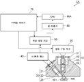
도 1에 나타내지는 것처럼, 광학 측정 장치(1)는 조사 광학계(10)와, 검출 광학계(20)(광 검출부)와, 광원 구동 회로(30)와, IV 변환 앰프(40)와, 파형 생성 회로(50)와, 캔슬 회로(60)(신호 처리부)와, 타이밍 생성기(70)와, AD 변환기(80)와, CPU(90)를 구비한다. As shown in Fig. 1, the
조사 광학계(10)는 측정 대상물인 면역 크로마토 시험편(100)(시료)을 향해서 여기광(조사광)을 조사한다. 조사 광학계(10)는 광원(11)과, 애퍼처(12)와, 여기광 필터(13)와, 콜리메이트 렌즈(14)를 가지고 있다. 광원(11)은 면역 크로마토 시험편(100)(시료)에 여기광을 조사한다. 광원(11)은, 예를 들면 반도체 발광소자이다. 본 실시 형태에서는, 광원(11)은 발광 다이오드(LED)인 것으로 설명하지만 이것으로 한정되지 않고, 예를 들면 광량을 확보할 수 있도록 LD가 이용되어도 된다. 애퍼처(12)는 광원(11)으로부터 출사된 광을, 원하는 광속 단면(斷面)을 가지는 광으로 정형하기 위한 광속 정형 부재이다. 여기광 필터(13)는 애퍼처(12)를 통해서 도달한 여기광에 대해서, 여기에 필요한 파장을 필터링하는 파장 선택 필터이다. 여기광 필터(13)는, 예를 들면 유전체 다층막 필터나 색 유리 필터 등의 광학 필터이며, 보다 상세하게는 특정 파장대(형광 시약의 여기 파장)만을 투과시키는 유전체 다층막 필터로 이루어지는 밴드 패스 필터이다. 콜리메이트 렌즈(14)는 여기광 필터(13)에 의한 필터링 후의 여기광을, 면역 크로마토 시험편(100)(상세하게는 면역크로마토멤브레인의 측정 대상부) 상에 결상시키는 렌즈이다. The irradiation
검출 광학계(20)는 여기광에 기인하는 검출광을 검출한다. 구체적으로는, 검출 광학계(20)는 면역 크로마토 시험편(100)으로부터의 형광을 검출한다. 그렇지만, 현실적으로는, 검출 광학계(20)에는, 면역 크로마토 시험편(100)으로부터의 형광(면역크로마토멤브레인의 측정 대상부로부터의 형광)에 더하여, 상술한 여기광 자체에 기인하는 산란광도 포함한 광인 검출광이 입사되어, 해당 검출광을 검출하게 된다. 검출 광학계(20)는 광 검출 소자(21)와, 형광 필터(22)와, 집광 렌즈(23)를 가지고 있다. 검출광은 집광 렌즈(23)에 의해서 집광되어, 형광 필터(22)를 통해서 광 검출 소자(21)로 입사된다. 형광 필터(22)는 면역 크로마토 시험편(100)으로부터의 검출광에 대해서, 형광 이외의 광이 광 검출 소자(21)에 도달하는 것을 억제하기 위해서 마련되는 파장 선택 필터이다. 형광 필터(22)는, 예를 들면 유전체 다층막 필터나 색 유리 필터 등의 광학 필터이며, 보다 상세하게는 특정 파장대만을 투과시키는 유전체 다층막 필터와 색 유리 필터를 조합 밴드 패스 필터이다. 그렇지만, 예를 들면 여기광 파장 및 형광 파장이 가까운 경우 등에 있어서는, 형광 필터(22)에 의해서 형광 파장을 가지는 형광을 적절히 투과시키면서 여기광 파장을 가지는 산란광만을 효율 좋게 차단하는 것은 곤란하다. 또, 일반적으로, 효율이 좋은 파장 선택 필터로서 범용되는 유전체 다층막 필터는 광의 입사각도에 따라서 특성이 변화해 버린다. 그 때문에 본 실시 형태에 있어서는, 형광 필터(22)를, 유전체 다층막 필터와 색 유리 필터의 조합에 의해서 구성함으로써, 경사 방향으로부터의 산란광을 색 유리 필터에 의해서 효과적으로 차단하고 있다. 그렇지만, 역시 파장 선택만으로는 충분한 효과를 얻기 어려워, 다양한 조건을 가진 산란광의 진입을 효율 좋게 막는 것은 곤란하다. 이하에서는, 형광 필터(22)를 마련함으로써, 광 검출 소자(21)에 도달하는 검출광에는 산란광이 포함되어 버려 있는 것으로 설명한다. The detection
광 검출 소자(21)는 형광 필터(22)에 의한 필터링 후의 검출광을 검출하는 광 센서이다. 광 검출 소자(21)는, 예를 들면 반도체 수광 소자이다. 본 실시 형태에서는, 광 검출 소자(21)는 포토 다이오드(PD)로서 설명하지만 이것으로 한정되지 않고, 후술하는 광원(11)으로부터의 여기광의 변조 주파수에 대응하여 고속 응답할 수 있는 것이면, 애벌란시 포토 다이오드(APD) 또는 광 전자 증배관(PMT) 등이어도 된다. 광 검출 소자(21)는, 상세하게는, 여기광이 조사된 면역 크로마토 시험편(100)(상세하게는 면역크로마토멤브레인의 측정 대상부에 있어서의 항원항체 복합물의 형광 시약)으로부터 생기는 형광, 및 여기광에 기인하는 광으로서 여기광과 위상차가 없는 상술한 산란광이 포함되는 검출광을 검출한다. 광 검출 소자(21)는, 검출광에 따른 검출 신호를 IV 변환 앰프(40)에 출력한다. The
광원 구동 회로(30)는 LED인 광원(11)에 구동 전류를 출력함으로써 광원(11)을 구동시키는 회로이다. 광원 구동 회로(30)는 타이밍 생성기(70)로부터, 기준이 되는 사인파 모양의 주파수 신호의 입력을 받는다. 광원 구동 회로(30)는 입력된 기준이 되는 주파수 신호에 기초하여 구동 전류의 주파수를 변조한다. 즉, 광원 구동 회로(30)는 여기광을 출력하는 광원(11)의 변조 주파수를 설정한다. 이것에 따라서, 광원(11)으로부터 출력되는 여기광의 주파수가 변조되어, 광원(11)으로부터의 광량(여기광량)이 사인파 모양으로 변화된다. 또한, 변조 주파수는 이용되는 형광 시약의 형광 수명에 기초하여 결정되어도 된다. 예를 들면, 형광 시약으로서 형광 수명이 수 밀리초인 유로퓸이 이용되는 경우에는 변조 주파수가 1kHz 정도로 되고, 형광 수명이 수 10나노초인 Q-dot가 이용되는 경우에는 변조 주파수가 100MHz 정도로 되고, 형광 수명이 수 나노~수십 나노초인 유기 색소가 이용되는 경우에는 변조 주파수가 1GHz 정도로 되어도 된다. The light
일반적으로, 형광 수명은 형광 강도가 피크값으로부터 1/e(약 37%)로 떨어질 때까지의 시간이 된다. 이 형광 수명의 정의로부터 역산하면, 예를 들면 형광 수명이 수 밀리초인 유로퓸을 이용하는 경우의 최적인 변조 주파수는 1kHz, 형광 수명이 수 나노~수십 나노초인 유기 색소를 이용하는 경우의 최적인 변조 주파수는 100MHz~1GHz 정도가 바람직하다고 생각할 수 있다. 그러나, 유로퓸 시약을 이용하여 실제로 변조 주파수에 대한 형광 유래의 신호 출력을 측정했더니, 형광 수명으로부터 정해지는 주파수보다도 저주파로 변조하는 쪽이, 형광 강도가 높아지고, 여기광에 대한 형광 신호의 비율도 커지는 것이 판명되었다(도 12 참조). 도 12에 나타내지는 것처럼, 형광 수명으로부터 정해지는 주파수인 1kHz보다도 저주파측에 있어서, 형광 강도가 높게 되어 있다. 구체적으로는, 형광 수명을 1/e가 아니라, 「형광 강도의 피크값이 1%로 떨어질 때까지의 시간」이라고 정의하고, 그 시간으로부터 변조 주파수를 구함으로써, 형광 강도를 높게 할 수 있었다. 이 경우, 유로퓸이면 형광 수명이 약 10ms가 되고, 이것으로부터 정해지는 광원(11)의 변조 주파수는 약 100Hz가 된다. In general, the fluorescence lifetime is the time until the fluorescence intensity drops to 1/e (about 37%) from the peak value. Calculating backward from this definition of the fluorescence lifetime, for example, the optimal modulation frequency in the case of using europium with a fluorescence lifetime of several milliseconds is 1 kHz, and the optimal modulation frequency in the case of using an organic dye having a fluorescence lifetime of several nanoseconds to several tens of nanoseconds is It can be considered that about 100 MHz to 1 GHz is preferable. However, when the fluorescence-derived signal output was actually measured with respect to the modulation frequency using a europium reagent, the fluorescence intensity increased and the ratio of the fluorescence signal to the excitation light increased when the frequency was lower than the frequency determined by the fluorescence lifetime. It turned out (see Fig. 12). As shown in Fig. 12, the fluorescence intensity is higher on the low frequency side than 1 kHz, which is a frequency determined from the fluorescence lifetime. Specifically, the fluorescence intensity could be increased by defining the fluorescence lifetime not as 1/e but as "the time until the peak value of the fluorescence intensity drops to 1%" and obtaining the modulation frequency from that time. In this case, if it is europium, the fluorescence lifetime is about 10 ms, and the modulation frequency of the
상술한 것처럼, 광원 구동 회로(30)는 광원(11)의 변조 주파수를, 형광 강도를 고려해서 결정해도 된다. 구체적으로는, 광원 구동 회로(30)는 광원(11)의 변조 주파수를, 형광 강도가 피크값으로부터 1/e로 떨어질 때까지의 시간인 형광 수명에 대응하는 값(상세하게는, 1/형광 수명)보다도 낮게 한다. 광원 구동 회로(30)는 광원(11)의 변조 주파수를, 형광 수명에 대응하는 값보다도 낮고, 또한 상용 주파수(50Hz, 60Hz)보다도 높게 설정하고, 예를 들면, 100Hz 부근으로서 상용 주파수의 배파(倍波)를 방지함으로써 노이즈의 영향을 저감시킨 110Hz 정도로 설정한다. 광원 구동 회로(30)는 광원(11)의 변조 주파수를, 100Hz 부근의 다른 값, 예를 들면 90Hz, 80Hz, 70Hz, 또는 130Hz 등으로 설정해도 된다. As described above, the light
IV 변환 앰프(40)는 광 검출 소자(21)로부터 출력된 전류 신호(검출 신호)를 전압 신호로 변환한다. IV 변환 앰프(40)는 전압 신호로 변환한 검출 신호를 파형 생성 회로(50)에 출력한다. The
파형 생성 회로(50)는 IV 변환 앰프(40)으로부터 출력된 검출 신호에 기초하여, 검출 신호의 파형을 생성하는 회로이다. 파형 생성 회로(50)는 타이밍 생성기(70)로부터 기준이 되는 주파수 신호의 입력을 받는다. 타이밍 생성기(70)는 광원 구동 회로(30) 및 파형 생성 회로(50)에 대해서 같은 타이밍에서 기준이 되는 주파수 신호를 입력한다. 파형 생성 회로(50)는 생성한 파형(검출 신호)의 정보를 캔슬 회로(60)에 출력한다. The
캔슬 회로(60)는 파형 생성 회로(50)에 의해서 생성된 파형(검출 신호)을 처리하는 신호 처리부이다. 캔슬 회로(60)는 형광과 산란광에 있어서의 위상의 차이(위상차)에 기초하여, 검출 신호로부터 산란광에 따른 신호 성분을 제거한다. 또한, 캔슬 회로(60)는 광원 구동 회로(30) 및 파형 생성 회로(50)와 같은 타이밍에서, 타이밍 생성기(70)로부터 기준의 주파수 신호의 입력을 받음으로써, 여기광(즉 산란광)의 위상의 정보를 취득한다. 이것에 의해, 캔슬 회로(60)에 있어서, 형광과 산란광에 있어서의 위상차에 기초하는, 산란광의 신호 성분의 제거가 가능하게 되어 있다. 캔슬 회로(60)의 처리의 상세에 대하여, 도 2~도 4를 참조하여 설명한다. The cancel
도 2는 형광과 산란광의 위상차를 설명하는 개념도이다. 도 2에 나타내지는 것처럼, 광원부(L)로부터 사인파 모양의 여기광이 조사된 시료(S)로부터의 사인파 모양의 검출광(광 검출부(D)에서 검출되는 검출광)에는, 사인파 모양의 산란광 및 형광이 포함되어 있다. 또한, 광원부(L)로부터의 여기광은, 사인파 모양으로 한정하지 않고, 구형파 등의 주기적 변조 파형이어도 되고, 그 경우, 검출광(산란광 및 형광)도 여기광과 마찬가지의 주기적 변조 파형을 가진다. 그리고, 산란광은 여기광과 위상차가 없는 광인 것에 대하여, 형광은 여기광에 따라 시료(S)로부터 생기는 광이며, 산란광에 대해서 수 10밀리초로부터 나노초 정도, 위상이 지연되어 검출되게 된다. 본 발명자 등은, 이러한 위상차에 주목하여, 검출광으로부터 산란광만을 제거하여 형광만을 취출하는 수법을 찾아냈다. 또한, 도 2에 있어서는, 광원부(L)의 광축 상에 시료(S) 및 광 검출부(D)가 배치되어 있기 때문에, 여기광의 광축과 교차하는 방향으로 방출된 형광을 검출하는 도 1과 달리, 여기광의 광축과 동축 방향으로 방출된 형광을 검출하고 있다. 이러한 경우, 검출광에 포함되는 것은 형광 및 산란광에 더하여, 여기광 그 자체가 포함될 가능성도 있다. 또, 광 검출부(D)에 입사되는, 여기광에 기인하는 광의 광량도 커질 가능성이 높다. 그 때문에, 본 수법에 의한 형광의 취출이 유효하게 된다. 2 is a conceptual diagram illustrating a phase difference between fluorescence and scattered light. As shown in FIG. 2 , the sine wave-shaped detection light (detection light detected by the photodetector D) from the sample S to which the sine-wave excitation light is irradiated from the light source part L includes sine wave-shaped scattered light and Fluorescence is included. Further, the excitation light from the light source unit L is not limited to a sine wave form, but may be a periodic modulated waveform such as a square wave. In that case, the detection light (scattered light and fluorescence) also has a periodic modulated waveform similar to that of the excitation light. While the scattered light is light having no phase difference with the excitation light, the fluorescence is light generated from the sample S in response to the excitation light, and is detected with a phase delay of several tens of milliseconds to about nanoseconds relative to the scattered light. The inventors of the present invention paid attention to this phase difference and found a method of extracting only the fluorescence by removing only the scattered light from the detection light. In addition, in FIG. 2, since the sample S and the photodetector D are disposed on the optical axis of the light source unit L, unlike FIG. 1 in which fluorescence emitted in a direction crossing the optical axis of the excitation light is detected, Fluorescence emitted coaxially with the optical axis of the excitation light is detected. In this case, in addition to fluorescence and scattered light, there is a possibility that excitation light itself is also included in the detection light. In addition, there is a high possibility that the light amount of the light caused by the excitation light entering the photodetector D is also increased. Therefore, extraction of fluorescence by this technique becomes effective.
도 3은 산란광의 제거(캔슬) 수법에 대해 설명하는 도면이다. 도 3은 검출광 중 산란광의 파형만을 나타내고 있다. 또한, 이 파형은 여기광의 파형과 동일하다. 도 3에 있어서 가로축은 시간, 세로축은 진폭을 나타내고 있다. 도 3에 나타내지는, 산란광의 위상에 따른 파형에 대해서, 예를 들면 1주기의 1/4의 시간 단위로 분리(시간 영역을 분리)하고, 각 시간 영역 1~4에 대해 각각 적분하면, 각 시간 영역 1~4에 있어서의 산란광의 출력를 얻을 수 있다. 여기서, 각 시간 영역 1~4의 적분값 각각에, 어떤 승수를 곱해 전부 더하면, 출력의 합계를 0으로 할 수 있다. 즉, 각 시간 영역 1~4의 출력의 절대값은 같고, 시간 영역 1 및 2의 진폭의 범위는 양, 시간 영역 3 및 4의 진폭의 범위는 음인 바, 도 3에 나타내지는 것처럼, 시간 영역 1에 대해 승수 「-1」이 곱해져 증폭되면 시간 영역 1의 출력은 「양×음」으로 음의 값이 되고, 시간 영역 2에 대해 승수 「+1」이 곱해져 증폭되면 시간 영역 2의 출력은 「양×양」으로 양의 값이 되고, 시간 영역 3에 대해 승수 「+1」이 곱해져 증폭되면 시간 영역 3의 출력은 「음×양」으로 음의 값이 되고, 시간 영역 4에 대해 승수 「-1」이 곱해져 증폭되면 시간 영역 4의 출력은 「음×음」으로 양의 값이 된다. 이 때문에, 소정의 승수가 곱해져 증폭된 각 시간 영역 1~4의 적분값을 전부 더하면, 각 값이 상쇄되어, 출력의 합계가 0이 된다. 이와 같이, 산란광에 따른 신호 성분에 대해서는, 산란광의 위상에 따른 소정의 시간 단위로 분리하고, 분리한 각 성분을 각각 증폭하고, 증폭한 각 성분을 합성함으로써, 제거할(출력을 0으로 할) 수 있다. Fig. 3 is a diagram explaining a method of removing (cancelling) scattered light. 3 shows only the waveform of scattered light among detection light. Also, this waveform is the same as that of the excitation light. In Fig. 3, the horizontal axis represents time, and the vertical axis represents amplitude. For the waveform according to the phase of the scattered light shown in FIG. 3, for example, if it is separated in time units of 1/4 of one period (time domain is separated) and integrated for each
도 4는 형광 측정 수법에 대해 설명하는 도면이다. 도 4는 검출 신호에 포함되는 산란광 및 형광의 파형을 나타내고 있다. 도 4에 있어서 가로축은 시간, 세로축은 진폭을 나타내고 있다. 상술한 것처럼, 산란광에 따른 신호 성분에 대해서는, 산란광의 위상에 따른 소정의 시간 단위로 분리하고, 분리한 각 성분을 각각 증폭하고, 증폭한 각 성분을 합성함으로써, 제거할(출력을 0으로 할) 수 있다. 여기서, 도 4에 나타내지는 것처럼, 형광에 대해서는 산란광에 대해서 위상차를 가지고 있기 때문에, 산란광의 위상에 따른 소정의 시간 단위로 분리하면, 각 시간 영역 1~4의 적분값이 같은 값이 되지 않기 때문에, 산란광과 같은 승수를 곱해 각각 증폭하여 모두 더한 값은 0이 아닌 값이 출력된다. 이와 같이, 산란광 및 형광에 대해서, 같은 시간 영역으로 분리하여 증폭하여 합성함으로써, 산란광의 신호 성분을 제거하면서 형광의 출력 강도를 검파 출력할 수 있다. 4 is a diagram explaining a fluorescence measurement technique. 4 shows waveforms of scattered light and fluorescence included in the detection signal. In Fig. 4, the horizontal axis represents time, and the vertical axis represents amplitude. As described above, the signal component according to the scattered light is separated by a predetermined time unit according to the phase of the scattered light, each separated component is amplified, and each amplified component is synthesized to be removed (the output is set to 0). ) can. Here, as shown in FIG. 4, since fluorescence has a phase difference with respect to scattered light, if separated by a predetermined time unit according to the phase of scattered light, the integral values of each
이와 같이, 캔슬 회로(60)는 검출 신호에 대해서, 산란광의 위상에 따른 소정의 시간 단위로 분리하고, 분리한 검출 신호의 각 성분을 각각 증폭하고, 증폭한 각 성분을 합성함으로써, 검출 신호로부터 산란광에 따른 신호 성분을 제거하여, 형광의 신호 성분를 얻을 수 있다. 캔슬 회로(60)는 산란광에 따른 신호 성분을 제거한 신호(즉 형광의 신호 성분만으로 된 신호)인 형광 신호를 AD 변환기(80)에 출력한다. 또한, 소정의 시간 단위로서 1주기의 1/4의 시간을 예시했지만 이것으로 한정되지 않고, 합성 후에 있어서 산란광에 따른 신호 성분을 제거 가능한 시간 단위이면 어떠한 시간 단위여도 된다. 또, 증폭에 있어서의 승수로서 「+1」 및 「-1」을 예시했지만 이것으로 한정되지 않고, 합성 후에 있어서 산란광에 따른 신호 성분을 제거 가능한 승수이면 어떠한 승수여도 된다. In this way, the canceling
AD 변환기(80)는 캔슬 회로(60)로부터 출력된 형광 신호에 대해서, AD 변환을 행하여 디지털값으로 변환하여, CPU(90)에 출력한다. CPU(90)는 AD 변환기(80)로부터 출력된 디지털 신호(형광 신호)에 대해서, 소정의 제어·신호 처리를 행한다. CPU(90)는 신호 처리 결과를 예를 들면 시리얼 통신으로 외부의 컴퓨터에 전송해도 된다. 또, CPU(90)는 타이밍 생성기(70)로부터 출력되는 신호, 즉 광학 측정 장치(1)에 있어서의 각종 동작 타이밍을 결정하는 신호를 생성하여 타이밍 생성기(70)에 출력해도 된다. 또한, CPU(90)를 대신하여 FPGA가 이용되어도 된다. 이상의 처리에 의해서, 광학 측정 장치(1)는 검출광으로부터 산란광의 영향을 제거하여, 형광 시약의 형광에 관한 신호만를 얻을 수 있다. The
다음에, 광학 측정 장치(1)가 행하는 형광 측정 처리(광학 측정 방법)에 대해서, 도 5를 참조하여 설명한다. Next, a fluorescence measurement process (optical measurement method) performed by the
도 5는 광학 측정 장치(1)에 의한 형광 측정 처리를 나타내는 순서도이다. 도 5에 나타내지는 것처럼, 형광 측정 처리에서는, 처음에, 조사 광학계(10)(광원 부)의 광원(11)이, 면역 크로마토 시험편(100)(시료)을 향해서 여기광을 조사한다(스텝 S1). 면역 크로마토 시험편(100)(상세하게는, 면역크로마토멤브레인의 측정 대상부에 있어서의 항원항체 복합물)에 대해서 여기광이 조사됨으로써, 항원항체 복합물의 형광 시약으로부터 형광이 방출된다. 한편, 여기광이 면역 크로마토 시험편(100)에서 산란되어, 산란광이 생긴다. 5 is a flow chart showing fluorescence measurement processing by the
이어서, 검출 광학계(20)(광 검출부)의 광 검출 소자(21)가 상술한 형광 및 산란광을 포함하는 검출광을 검출한다(스텝 S2). 광 검출 소자(21)는 검출광을 IV 변환 앰프(40)에 출력한다. 그리고, IV 변환 앰프(40)에 있어서 광 검출 소자(21)로부터 출력된 전류 신호(검출 신호)가 전압 신호로 변환되고, 파형 생성 회로(50)에 있어서 검출 신호의 파형이 생성된 후에, 캔슬 회로(60)(신호 처리부)가 형광과 산란광에 있어서의 위상차에 기초하여, 검출 신호로부터 산란광에 따른 신호 성분을 제거한다(스텝 S3). 구체적으로는, 캔슬 회로(60)는 검출 신호에 대해서, 산란광의 위상에 따른 소정의 시간 단위로 분리하고, 분리한 검출 신호의 각 성분을 각각 증폭하고, 증폭한 각 성분을 합성함으로써, 검출 신호로부터 산란광에 따른 신호 성분을 제거하여, 형광의 신호 성분을 얻는다. 그 후, AD 변환기(80)에 있어서 형광 신호가 디지털값으로 변환되어, CPU(90)에 있어서 소정의 제어·신호 처리가 행해짐으로써, 형광에 관한 신호를 얻을 수 있다. Then, the
또한, 광학 측정 장치(1)에서는, 캔슬 회로(60)에 있어서 검출 신호로부터 산란광에 따른 신호 성분을 제거하는 것으로 설명했지만, 이것으로 한정되지 않는다. 즉, 도 6에 나타내지는 광학 측정 장치(1A)와 같이, 캔슬 회로(60)를 마련하지 않고, AD 변환기(80)에 있어서의 A/D 변환 후에, CPU(90A)(신호 처리부)에 있어서 검출 신호로부터 산란광에 따른 신호 성분을 제거하는 처리를 행해도 된다. 이 경우에는, 캔슬 회로(60)를 마련할 필요가 없기 때문에, 장치의 소형화에 기여할 수 있다. In addition, in the
다음에, 상술한 실시 형태에 있어서 설명한 특정 신호 성분(노이즈)의 제거에 관해서, 도 7~도 14를 참조하여 보다 구체적으로 설명한다. Next, the elimination of the specific signal component (noise) described in the above-described embodiment will be described in more detail with reference to FIGS. 7 to 14 .
도 7은 노이즈 성분의 제거에 대해 설명하는 도면이다. 도 7의 (a)는 여기광에 기인하는 산란광에 따른 신호 성분(노이즈)의 제거를 행하지 않은 경우의 검출광의 강도, 도 7의 (b)는 여기광에 기인하는 산란광에 따른 신호 성분(노이즈)의 제거를 행했을 경우의 검출광의 강도를 나타내고 있다. 도 7의 (a) 및 도 7의 (b)에 있어서 세로축은 검출광의 강도를 나타내고 있고, 가로축은 시료(500)의 측정 영역인 측정부(501)에 있어서의 위치를 나타내는 채널이다. 1채널은 예를 들면 0.02mm이다. 도 7의 (c)는 도 7의 (a) 및 도 7의 (b)의 채널의 위치에 대응하는 시료(500)의 영역을 나타내는 도면이다. 도 7의 (c)에 나타낸 시료(500)를 확대한 모식도가 도 8이다. 도 8에 나타내지는 것처럼, 시료(500)는 검체가 적하되는 적하부(502)와, 형광 시약으로 표지된 검출 항체를 유지하는 유지부(503)와, 포착 항체를 측정 대상부(504)에 고정한 측정부(501)가 상류에서 하류를 향해서 배치되어 있다. 형광 시약은 예를 들면 DTBTA-Eu3+이다. 측정부(501)는, 예를 들면 백색의 면역크로마토멤브레인의 일부이기 때문에, 여기광을 산란하기 쉽다. 7 is a diagram explaining the removal of noise components. Fig. 7(a) shows the intensity of the detection light when the signal component (noise) associated with the scattered light caused by the excitation light is not removed, and Fig. 7(b) shows the signal component (noise) associated with the scattered light caused by the excitation light. ) shows the intensity of the detection light when removal is performed. In FIGS. 7A and 7B , the vertical axis represents the intensity of the detection light, and the horizontal axis represents a channel representing the position in the measuring
이러한 시료(500)에 대해서, 적하부(502)에 검체를 적하하면, 검체는 모세관 현상에 의해 하류측으로 이동한다. 검체 중에 피검출 물질이 있는 경우, 유지부(503)의 검출 항체와 피검출 물질이 반응하여 복합체를 형성하고, 이 복합체가 측정부(501)를 하류측으로 이동해 간다. 그리고, 복합체가 측정부(501) 상의 측정 대상부(504)에 도달했을 때, 복합체가 측정 대상부(504)의 포착 항체에 포착되어, 피검출 물질, 검출 항체, 및 포착 항체의 3개에 의한 복합체가 형성된다. 이 상태에서 측정 영역인 측정부(501)에 대해서 집광 위치(채널)를 변화시키면서 여기광이 조사됨으로써, 도 7의 (a) 및 도 7의 (b)에 나타내지는 것 같이 채널마다의 검출광 강도를 도출할 수 있다. 도 7의 (a) 및 도 7의 (b)에 있어서 검출광 강도가 다른 것에 비해서 커져 있는 채널은, 복합체가 포착되어 있는 측정 대상부(504)의 위치에 대응하는 채널이다. Regarding such a
도 7의 (a)에 나타내지는 것처럼, 산란광에 따른 신호 성분(노이즈)의 제거가 행해져 있지 않은 경우에는, 검출광에는 형광뿐만이 아니라 산란광이 포함되기 때문에, 검출광 강도가 커지고 있다. 그리고, 이러한 노이즈는 여기광량을 크게 함에 따라 커지기 때문에, 도 7의 (a)에 나타내지는 것처럼, 여기광량을 2배로 하면 노이즈도 마찬가지로 2배 정도로 되어 있다. 일반적으로 S/N을 향상시키는 방법으로서, 여기광량을 증가시킴으로써 형광 시그널량을 증가시키는 방법을 생각할 수 있지만, 상술한 것처럼, 도 7의 (a)와 같이 여기광량에 따라 노이즈도 증가하는 양태에 있어서는, S/N을 향상시키는 것이 어렵다. 또한, 여기광량을 증가시킴으로써 다이나믹 레인지가 좁아진다고 하는 문제도 있다. As shown in (a) of FIG. 7 , when the signal component (noise) associated with scattered light is not removed, detection light includes not only fluorescence but also scattered light, so detection light intensity increases. And, since such noise increases as the amount of excitation light is increased, as shown in Fig. 7(a), when the amount of excitation light is doubled, the noise is also about twice as large. In general, as a method of improving S / N, a method of increasing the amount of fluorescence signal by increasing the amount of excitation light can be considered, but as described above, as shown in FIG. , it is difficult to improve S/N. In addition, there is also a problem that the dynamic range is narrowed by increasing the amount of excitation light.
한편으로, 도 7의 (b)에 나타내지는 것처럼, 산란광에 따른 신호 성분(노이즈)의 제거를 행했을 경우에는, 검출광에는 대체로 형광만이 포함되어 있어, 검출하고 싶은 신호(형광에 기초하는 신호)만을 검출할 수 있다. 이 경우에는, 노이즈가 거의 0이기 때문에, 도 7의 (b)에 나타내지는 것처럼, 여기광량을 증가시켜도(예를 들면 2배로 해도), 광 검출기가 포화되지 않는 한, 여기광(산란광)의 영향을 거의 0으로 캔슬할 수 있어, 노이즈가 극단적으로 커지는 일이 없다. 이상과 같이, 도 7의 (b)에 나타내지는 것과 같이 노이즈의 제거를 행하는 구성에 있어서는, 여기광을 증가시켰을 경우에 노이즈 성분을 거의 0으로 캔슬한 상태에서 시그널 성분만을 증가시킬 수 있기 때문에, S/N의 향상으로 이어진다. 해당 구성은 노이즈 성분에 매우 강하기 때문에, 여기광량을 증가시키는 것이나 IV 변환 앰프의 증배율을 올리는 것이 가능해진다. On the other hand, as shown in Fig. 7(b), when the signal component (noise) associated with scattered light is removed, the detection light generally contains only fluorescence, and the signal to be detected (based on fluorescence) signal) can be detected. In this case, since the noise is almost zero, even if the amount of excitation light is increased (for example, even if it is doubled) as shown in Fig. 7(b), as long as the photodetector is not saturated, the The effect can be canceled to almost zero, and the noise does not become extremely large. As described above, in the configuration for removing noise as shown in Fig. 7(b), when the excitation light is increased, only the signal component can be increased while the noise component is canceled to almost zero. It leads to improvement of S/N. Since this configuration is very resistant to noise components, it becomes possible to increase the amount of excitation light and to increase the multiplication factor of the IV conversion amplifier.
도 9는 S/N의 정의에 대해 설명하는 도면이다. 도 9는 채널마다의 검출광의 강도(측정 영역의 각 위치에 있어서의 검출광의 강도)의 일례를 나타내고 있다. 도 9에 나타내지는 것처럼, 검출광의 강도 10count 부근에 ±4 정도의 흔들림 성분이 존재하고 있다. 이러한 베이스 광량의 흔들림(표준 편차)은, 형광 물질 등이 아무것도 도포되어 있지 않은 측정부(501)(혹은, 계측 상태와 마찬가지로 젖은 상태로 된 측정부(501))에 여기광을 스캔하여 취득되는 값이다. 이하에서는, 해당 베이스 광량의 흔들림을 노이즈(N)라고 정의한다. 또, 시그널(S)은 「측정 대상부(504)의 피크 형광 강도로부터 전 채널에 있어서의 측정 대상부(504)의 위치를 제외한 노이즈 성분의 평균값을 뺀 값」이라고 정의한다. S/N은 상기로 정의한 시그널을 노이즈로 나눈 값이라고 정의한다. 9 is a diagram explaining the definition of S/N. Fig. 9 shows an example of the intensity of the detection light for each channel (the intensity of the detection light at each position in the measurement area). As shown in Fig. 9, a fluctuation component of about ±4 exists around 10 counts of the intensity of the detection light. The fluctuation (standard deviation) of the base light quantity is obtained by scanning the excitation light on the
또한, 도 9에 나타내지는 예에서는, 노이즈의 값이 10count 정도 오프셋되어 있다. 후술하는 캘리브레이션 처리를 행함으로써, 원리적으로는 노이즈의 값은 거의 0으로 캔슬된다. 그러나, 노이즈의 값에 따른 백그라운드는 편차가 있는 바, 소프트웨어에서의 해석의 관점으로부터는 신호가 항상 플러스의 값이 되는 것이 바람직하기 때문에, 백그라운드의 오프셋 처리를 행하고 있다. 또한, 오프셋량은 신호가 다이나믹 레인지 내(0~4096count 내)에 들어가도록 설정된다. 오프셋량은 다이나믹 레인지의 관점으로부터 최대한 줄이면서, 측정부(501)에 여기광을 스캔함으로써 얻어지는 백그라운드의 신호가 항상(거의 확실하게) 플러스의 값이 되도록 설정되어 있다. 구체적으로는, 오프셋량은, 예를 들면, 형광 물질 등이 아무것도 도포되어 있지 않은 측정부(501)(혹은, 계측 상태와 마찬가지로 젖은 상태로 된 측정부(501))에 여기광을 스캔하여 취득되는 검출광의 강도 평균값+그 강도 평균값의 6σ의 값으로 되어도 된다. 또한, 회로계에 돌발적인 노이즈가 뛰어들 경우에 대비하여, 상기에서 계산되는 오프셋량에 적당한 마진을 더해 최종적인 오프셋량으로 되어도 된다. 오프셋량은 다이나믹 레인지를 희생하지 않고 또한 신호가 마이너스로 출력되지 않도록 선택되고, 예를 들면 +20count 정도여도 된다. In the example shown in Fig. 9, the value of noise is offset by about 10 counts. By carrying out the calibration process described later, in principle, the value of the noise is canceled to almost zero. However, since the background varies depending on the noise value, it is desirable that the signal always be a positive value from the viewpoint of analysis in software, so background offset processing is performed. Also, the offset amount is set so that the signal falls within the dynamic range (within 0 to 4096 counts). The amount of offset is set so that the background signal obtained by scanning the
다음에, 산란광에 따른 신호 성분(노이즈)의 제거 수법으로 대해서, 구체적으로 설명한다. 광학 측정 장치(1)에서는, 록인 회로인 캔슬 회로(60)에 있어서 캘리브레이션 처리가 행해지고, 그 캘리브레이션 처리의 실시 결과가 고려되어, 검출 신호로부터 산란광에 따른 신호 성분(노이즈)이 제거된다. Next, a method for removing signal components (noise) associated with scattered light will be described in detail. In the
구체적으로는, 광학 측정 장치(1)를 이용한 광학 측정 방법에서는, 처음에, 시료(500)와는 상이한 캘리브레이션 처리용의 레퍼런스 부재(600)(도 15의 (a) 참조)에 여기광이 조사되도록, 조사 광학계(10)의 광학 헤드가 배치된다. 이어서, 조사 광학계(10)로부터의 여기광이 레퍼런스 부재(600)에 조사됨으로써 산란광(레퍼런스 부재(600)에서 산란된 여기광 성분)이 검출 광학계(20)의 광 검출 소자(21)에서 검출된다. 여기서 검출 광학계(20)에서 검출되는 광은, 기본적으로는, 레퍼런스 부재(600)에 있어서의 형광을 포함하지 않는 산란광만의 광이며, 캘리브레이션 처리에 이용되는 캘리브레이션 처리용 광이다. Specifically, in the optical measurement method using the
이어서, 캘리브레이션 처리가 실시된다. 구체적으로는, 광학 측정 장치(1)의 캔슬 회로(60)가 상술한 캘리브레이션 처리용 광에 따른 캘리브레이션 신호에 기초하여, 검출 신호로부터 산란광에 따른 신호 성분을 제거하기 위한 캘리브레이션 처리를 실시한다. 캘리브레이션 처리의 상세에 대해서는 후술한다. 그리고, 캘리브레이션 처리의 완료 후, 시료(500)의 측정 영역(측정부(501)) 상을 조사 광학계(10)의 광학 헤드로 스캔함으로써, 측정부(501)의 형광 정보가 취득된다. 구체적으로는, 캔슬 회로(60)가 상술한 캘리브레이션 처리의 실시 결과를 고려하여, 검출 신호로부터 산란광에 따른 신호 성분을 제거함으로써, 형광 정보를 취득한다. Then, calibration processing is performed. Specifically, the
다음에, 캘리브레이션 처리의 상세에 대하여 설명한다. 광학 측정 장치(1)의 캔슬 회로(60)는 예를 들면 FPGA(Field Programmable Gate Array)를 이용한 록인 회로이다. 캘리브레이션 처리에 있어서, 캔슬 회로(60)는 광원 구동 회로(30)에 의해서 설정되는 광원(11)의 변조 주파수(예를 들면 DDS(Direct Digital Synthesizer)의 주파수)에 맞춘, 캔슬 회로(60)의 동작 주파수로 주기를 새긴 주기 신호에 대해서 위상을 시프트시킨 록인용의 스위치 신호를 생성한다. 그리고, 록인 회로로서 기능하는 캔슬 회로(60)는 측정 신호인 캘리브레이션 신호, 및 참조 신호인 스위치 신호를 입력으로 하여, 산란광에 따른 신호 성분을 출력하고, 그 산란광에 따른 신호 성분의 전압값이 0에 근사하는 소정 범위 내(슬래시 레벨)가 되도록, 스위치 신호의 위상을 조정한다. Next, details of the calibration process will be described. The cancel
도 10은 캔슬 회로(60)의 FPGA 내부에서 캘리브레이션 처리에 이용하는 신호를 나타내고 있다. 도 10에 나타내지는 주기 신호는, 상술한 것처럼 DDS의 주파수에 맞춰 주기를 잘게 쪼갠 클록 신호이다. 기준 신호는 주기 신호로부터 임의의 위상에 있는(주기 신호에 대해서 위상을 시프트시킨), 주기 신호와 같은 주파수의 신호이며, 후술하는 XY 신호용 트리거이다. XY 신호는 상술한 록인용의 스위치 신호이며, 기준 신호를 트리거로 하여 만들어지는 신호이다. X 신호(제1 신호)는 기준 신호와 위상차가 없는 신호이다. Y 신호(제2 신호)는 기준 신호에 대해서 90도 위상이 시프트된 신호이다. 캔슬 회로(60)는 실제로는 X 신호 및 Y 신호에 더하여, 추가로, X 신호를 반전시킨 X′신호(제3 신호)와, Y 신호를 반전시킨 Y′신호(제4 신호)를 생성한다. X 신호, Y 신호, X′신호, 및 Y′신호는, 각각 독립된 전용의 회로에 의해서 생성된다. 산란광에 따른 신호 성분의 전압값이 슬래시 레벨이 되도록 스위치 신호의 위상을 조정한다는 것은, 즉, 캔슬 회로(60)로부터의 출력이 0V(또는 그것에 근사하는 값)가 될 때까지, 주기 신호에 대해서 기준 신호의 위상을 계속 시프트시키는 것이다. 10 shows signals used for calibration processing inside the FPGA of the cancel
도 11은 주기 신호에 대해서 기준 신호의 위상을 시프트시켜 출력이 0V가 되도록 조정하는 처리를 설명하는 도면이다. 여기서, 주기 신호, 기준 신호, 및 스위치 신호의 초기 상태의 위상 관계가 도 11의 (a)에 나타내지는 상태였던 것으로 한다. 그리고, 스위치 신호에 기초하여 도 11 중의 빗금친 구간에서 적분 처리가 이루어져, 출력(산란광에 따른 신호 성분의 전압값)이 슬래시 레벨이 아니고 또한 양의 값이었다고 한다. 이 경우, 도 11의 (b)에 나타내지는 것처럼, 스위치 신호의 위상을 지연시키도록 기준 신호의 위상이 조정된다. 즉, 캔슬 회로(60)는 캘리브레이션 처리에 있어서, 산란광에 따른 신호 성분의 전압값이 슬래시 레벨이 아니고 양의 값인 경우에는, 스위치 신호의 위상을 지연시키도록 조정한다. Fig. 11 is a diagram explaining a process of shifting the phase of a reference signal relative to a periodic signal and adjusting the output to be 0V. Here, it is assumed that the phase relationship between the initial state of the periodic signal, the reference signal, and the switch signal was a state shown in Fig. 11(a). Then, it is assumed that integration processing is performed in the hatched section in Fig. 11 based on the switch signal, and the output (voltage value of the signal component according to the scattered light) is not a slash level and is a positive value. In this case, as shown in (b) of FIG. 11, the phase of the reference signal is adjusted so as to delay the phase of the switch signal. That is, in the calibration process, the cancel
이제, 스위치 신호의 위상 조정이 이루어진 도 11의 (b)의 상태에 있어서도, 빗금친 구간의 적분 처리의 결과, 출력(산란광에 따른 신호 성분의 전압값)이 슬래시 레벨이 아니고 또한 양의 값이었다고 한다. 이 경우, 도 11의 (c)에 나타내지는 것처럼, 스위치 신호의 위상을 더 지연시키도록 기준 신호의 위상이 조정된다. Now, even in the state of FIG. 11(b) in which the phase of the switch signal is adjusted, as a result of the integration process of the hatched section, it is assumed that the output (the voltage value of the signal component according to the scattered light) is not a slash level but a positive value. do. In this case, as shown in (c) of FIG. 11, the phase of the reference signal is adjusted to further delay the phase of the switch signal.
이제, 스위치 신호의 위상 조정이 이루어진 도 11의 (c)의 상태에 있어서도, 빗금친 구간의 적분 처리의 결과, 출력(산란광에 따른 신호 성분의 전압값)이 슬래시 레벨이 아니고 또한 양의 값이었다고 한다. 이 경우, 도 11의 (d)에 나타내지는 것처럼, 스위치 신호의 위상을 더 지연시키도록 기준 신호의 위상이 조정된다. Now, even in the state of FIG. 11(c) in which the phase of the switch signal is adjusted, as a result of the integration process of the hatched section, it is assumed that the output (the voltage value of the signal component according to the scattered light) is not a slash level but a positive value. do. In this case, as shown in (d) of FIG. 11, the phase of the reference signal is adjusted to further delay the phase of the switch signal.
이제, 스위치 신호의 위상 조정이 이루어진 도 11의 (d)의 상태에 있어서, 빗금친 구간의 적분 처리의 결과, 출력(산란광에 따른 신호 성분의 전압값)이 슬래시 레벨이 아니고 또한 음의 값이었다고 한다. 이 경우, 도 11의 (e)에 나타내지는 것처럼, 스위치 신호의 위상을 진행시키도록 기준 신호의 위상이 조정된다. 즉, 캔슬 회로(60)는 캘리브레이션 처리에 있어서, 산란광에 따른 신호 성분의 전압값이 슬래시 레벨이 아니고 음의 값인 경우에는, 스위치 신호의 위상을 진행시키도록 조정한다. Now, in the state of (d) of FIG. 11 in which the phase of the switch signal is adjusted, it is assumed that the output (voltage value of the signal component according to the scattered light) is not a slash level but a negative value as a result of the integration process of the hatched section. do. In this case, as shown in (e) of FIG. 11, the phase of the reference signal is adjusted so as to advance the phase of the switch signal. That is, in the calibration process, the cancel
그리고, 스위치 신호의 위상을 진행시키도록 조정된 결과, 도 11의 (e)에 나타내지는 것처럼, 빗금친 구간의 적분 처리의 결과, 출력(산란광에 따른 신호 성분의 전압값)이 슬래시 레벨(0에 근사하는 소정 범위 내의 값)이 되면, 캘리브레이션 처리가 완료된다. Then, as a result of adjusting the phase of the switch signal to advance, as shown in FIG. A value within a predetermined range approximating to ), the calibration process is completed.
캘리브레이션 처리가 완료되면, 캔슬 회로(60)는 형광 성분 및 산란광 성분(여기광 성분)을 포함한 검출광에 따른 검출 신호와, 캘리브레이션 처리에 있어서 위상이 조정된 스위치 신호를 입력으로 하여, 검출 신호로부터 산란광 성분에 따른 신호 성분을 제거한다. When the calibration process is completed, the
도 13은 캘리브레이션 처리를 나타내는 순서도이다. 도 13에 나타내지는 것처럼, 캘리브레이션 처리에서는, 처음에, AD 변환기로의 입력이 소정의 오프셋 전압으로 전환되어 0레벨이 기억된다(스텝 S11). 그리고, 스위치의 전환에 의해 캔슬 회로(60)(록인 회로)의 신호가 AD 변환기에 입력된다(스텝 S12). 이 상태에서, 한 번 강제적으로 기준 신호의 위상이 시프트된다(스텝 S13). 캔슬 회로(60)(록인 회로)의 출력은 주기 신호에 대한 기준 신호의 위상이 0도와 180도일 때 0V가 되지만, 초기 상태에서 우연히 180도로 위상이 맞아 있었을 경우, 잘못 캘리브레이션 처리를 완료해 버려, 출력되는 신호의 양음이 반전되어 버리기 때문에, 후단의 회로의 구성에 의해서는 출력되는 신호를 검출할 수 없게 되는 경우가 있다. 이 점, 스타트시에 강제적으로 기준 신호의 위상을 시프트시킴으로써, 잘못 캘리브레이션 처리가 완료되어 버리는 것을 방지할 수 있다. 또, 이와 같이 하여 개시시의 위상을 맞춤으로써, 출력되는 신호의 양음이 고정된다. 그 결과, 출력되는 신호를 디지털값으로 변환했을 때의 부호 비트가 필요없게 되어, AD 변환기의 다이나믹 레인지를 유효하게 사용할 수 있다. 또, 음의 출력으로 계측하고 싶을 때는, 캘리브레이션 완료의 위상을 0도가 아니라 180도로 해도 된다. 13 is a flowchart showing a calibration process. As shown in Fig. 13, in the calibration process, first, the input to the AD converter is converted to a predetermined offset voltage, and the 0 level is stored (step S11). Then, by switching the switch, the signal of the cancel circuit 60 (lock-in circuit) is input to the AD converter (step S12). In this state, the phase of the reference signal is forcibly shifted once (step S13). The output of the cancellation circuit 60 (lock-in circuit) becomes 0V when the phase of the reference signal to the periodic signal is 0 degrees and 180 degrees, but if the phase coincides with 180 degrees by chance in the initial state, the calibration process is completed incorrectly, Since the positive and negative of the signal to be output is inverted, the signal to be output may not be detected depending on the configuration of the subsequent circuit. In this respect, by forcibly shifting the phase of the reference signal at the start, it is possible to prevent the calibration process from being completed by mistake. In addition, by matching the phases at the start in this way, the positive/negative of the output signal is fixed. As a result, there is no need for a code bit when converting an output signal into a digital value, and the dynamic range of the AD converter can be used effectively. Also, when measuring with a negative output, the calibration completion phase may be set to 180 degrees instead of 0 degrees.
스텝 S13이 완료되면, 현재의 AD 변환기의 입력값이 기록되고(스텝 S14), 캘리브레이션의 루프 처리가 실행된다. 우선, 현재의 AD 변환기의 입력값과 0레벨이 비교되어, AD 변환기의 입력값이 0레벨보다도 작은지(음의 값인지) 여부가 판정된다(스텝 S15). 스텝 S15에 있어서, AD 변환기의 입력값이 음의 값이라고 판정되면, DDS의 주파수에 따른 주기 신호에 대한 캔슬 회로(60)의 스위치 신호(즉 기준 신호)의 위상이 진행된다(스텝 S16). 한편으로, 스텝 S15에 있어서 AD 변환기의 입력값이 양의 값이라고 판정되면, 주기 신호에 대한 캔슬 회로(60)의 스위치 신호(즉 기준 신호)의 위상이 지연된다(스텝 S17). When step S13 is completed, the current input value of the AD converter is recorded (step S14), and the calibration loop process is executed. First, the current input value of the AD converter is compared with the 0 level, and it is determined whether or not the input value of the AD converter is smaller than the 0 level (negative value) (step S15). In step S15, when it is determined that the input value of the AD converter is a negative value, the phase of the switch signal (i.e., reference signal) of the cancel
그리고, AD 변환기의 입력값에 대해서, 부호가 변화하지 않고 슬래시 레벨로 되었는지 여부가 판정된다(스텝 S18). 스텝 S18에 있어서 부호가 변화하지 않고 슬래시 레벨로 되었다고 판정되면, 캘리브레이션 처리가 종료된다. 한편으로, 스텝 S18에 있어서 조건을 충족하고 있지 않다고 판정되면, 위상을 시프트시킴으로써 AD 변환기의 입력의 부호가 바뀌었는지 여부가 판정된다(스텝 S19). 스텝 S19에 있어서 변하지 않았다고 판정되었을 경우에는 재차 스텝 S14의 처리가 행해지고, 변했다고 판정되었을 경우에는 제어에 의한 위상의 변화폭이 현재 모양의 절반으로 변경되고(스텝 S20), 재차 스텝 S14의 처리가 행해진다. 이상이, 캘리브레이션 처리이다. Then, with respect to the input value of the AD converter, it is determined whether or not the sign has not changed and has reached the slash level (step S18). If it is determined in step S18 that the sign has not changed and has reached the slash level, the calibration process is ended. On the other hand, if it is determined that the condition is not satisfied in step S18, it is determined whether or not the sign of the input of the AD converter is changed by shifting the phase (step S19). When it is judged that it has not changed in step S19, the process of step S14 is performed again. All. The above is the calibration process.
본 양태에서는, 형광을 포함하지 않고 산란광을 포함하는 캘리브레이션 처리용 광을 검출하고, 캘리브레이션 처리용 광에 따른 캘리브레이션 신호에 기초하여, 검출 신호로부터 산란광에 따른 신호 성분을 제거하기 위한 캘리브레이션 처리를 실시하고, 그 캘리브레이션 처리의 실시 결과를 고려하여, 검출 신호로부터 산란광에 따른 신호 성분을 제거한다. 검출 신호로부터 산란광에 따른 신호 성분을 제거하기 위한 캘리브레이션 처리를, 산란광을 포함하는 캘리브레이션 처리용 광에 기초하여 미리 행함으로써, 검출 신호로부터 산란광에 따른 신호 성분을 적절히 제거할 수 있다. In this embodiment, light for calibration processing that does not include fluorescence but includes scattered light is detected, and based on the calibration signal according to the light for calibration processing, calibration processing for removing a signal component according to scattered light from the detection signal is performed, , the signal component according to the scattered light is removed from the detection signal in consideration of the result of the implementation of the calibration process. By preliminarily performing the calibration process for removing the signal component according to the scattered light from the detection signal based on the calibration light including the scattered light, the signal component according to the scattered light can be appropriately removed from the detection signal.
이와 같이 하여 산란광(노이즈)을 적절히 제거하는 것의 효과에 대해서, 도 14를 참조하여 설명한다. 도 14의 (a)는 산란광에 따른 신호 성분(노이즈)의 제거를 행하지 않은 경우의 검출광의 강도, 도 14의 (b)는 산란광에 따른 신호 성분(노이즈)의 제거를 행했을 경우의 검출광의 강도를 나타내고 있다. 도 14는 형광 시약으로서 DTBTA-Eu3+를 도포한 멤브레인을 계측했을 경우의 결과를 나타내고 있다. 도 14의 (a)에 나타내지는 것처럼, 노이즈의 제거가 행해져 있지 않은 경우에 있어서는, 여기광(산란광)의 백그라운드(BKG)를 위해서 약 330counts의 오프셋이 필요하게 되어 있다. 그리고, 노이즈(표준 편차)는 2.16, 시그널 강도는 404counts였다. 이것에 대해서, 도 14의 (b)에 나타내지는 것처럼, 노이즈의 제거가 행해져 있는 경우에 있어서는, 여기광이 멤브레인에 산란하는 것을 고려한 오프셋이 필요하지 않고, 소프트웨어상의 처리(신호의 값을 모두 플러스로 하는 처리)를 위한 최소한의 오프셋만이 행해지고 있다. 그리고, 노이즈(표준 편차)는 0.69, 시그널 강도는 1475counts로 할 수 있었다. 이와 같이, 노이즈의 제거가 행해져 있는 경우가 행해져 있는 경우에 있어서는 오프셋량이 작기 때문에, 광원으로부터의 여기광량 및 IV 변환 앰프의 증폭율을 올릴 수 있어, 시그널 강도를 적합하게 올릴 수 있다. 이 결과, 노이즈의 제거가 행해지지 않은 경우의 S/N가 187인데 대하여, 노이즈의 제거가 행해지는 경우의 S/N을 2140로 할 수 있어, S/N을 10배 이상 향상시킬 수 있다. The effect of appropriately removing scattered light (noise) in this way will be described with reference to FIG. 14 . Fig. 14(a) shows the intensity of detection light when signal components (noise) according to scattered light are not removed, and Fig. 14(b) shows the intensity of detection light when signal components (noise) according to scattered light are removed. represents strength. Fig. 14 shows the results of measuring a membrane coated with DTBTA-Eu3+ as a fluorescence reagent. As shown in Fig. 14(a), in the case where noise is not removed, an offset of about 330 counts is required for the background BKG of excitation light (scattered light). The noise (standard deviation) was 2.16 and the signal strength was 404 counts. On the other hand, as shown in (b) of FIG. 14 , in the case where noise is removed, offset considering the scattering of the excitation light on the membrane is not required, and software processing (all signal values are added) is not required. Only the minimum offset for processing) is performed. The noise (standard deviation) was 0.69 and the signal intensity was 1475 counts. In this way, since the amount of offset is small in the case where noise is removed, the amount of excitation light from the light source and the amplification factor of the IV conversion amplifier can be increased, and the signal intensity can be appropriately increased. As a result, while the S/N when noise is not removed is 187, the S/N when noise is removed can be 2140, and the S/N can be improved 10 times or more.
캘리브레이션 처리에 있어서, 광원(11)의 변조 주파수에 맞춘 캔슬 회로(60)의 동작 주파수로 주기를 새긴 주기 신호에 대해서 위상을 시프트시킨 록인용의 스위치 신호를 생성하고, 캘리브레이션 신호 및 스위치 신호를 입력으로 하여, 산란광에 따른 신호 성분을 출력하고, 그 산란광에 따른 신호 성분의 전압값이 0에 근사하는 소정 범위 내가 되도록, 스위치 신호의 위상을 조정하여, 검출 신호, 및 캘리브레이션 처리에 있어서 위상이 조정된 스위치 신호를 입력으로 하여, 검출 신호로부터 산란광에 따른 신호 성분을 제거해도 된다. 이와 같이, 록인 회로를 이용하여, 캘리브레이션 처리에 있어서 산란광에 따른 신호 성분의 전압값이 0에 근사하는 값이 되도록 스위치 신호의 위상이 조정됨으로써, 위상 조정 후의 스위치 신호를 입력으로 하여, 검출 신호로부터 산란광에 따른 신호 성분을 적절히 제거할 수 있다. In the calibration process, a switch signal for lock-in in which the phase is shifted with respect to a periodic signal whose cycle is engraved at the operating frequency of the
캘리브레이션 처리에 있어서, 산란광에 따른 신호 성분의 전압값이 소정 범위 내가 아니고 그 소정 범위의 값보다도 큰 경우에는, 스위치 신호의 위상을 지연시키도록 조정하고, 산란광에 따른 신호 성분의 전압값이 소정 범위 내는 아니고 그 소정 범위의 값보다도 작은 경우에는, 스위치 신호의 위상을 진행시키도록 조정해도 된다. 이것에 의해, 캘리브레이션 처리에 있어서 산란광에 따른 신호 성분의 전압값을, 적절히 0에 가까운 값으로 조정할 수 있다. In the calibration process, when the voltage value of the signal component according to the scattered light is not within the predetermined range and is greater than the value in the predetermined range, the phase of the switch signal is adjusted to be delayed, and the voltage value of the signal component according to the scattered light is within the predetermined range If it is not within the range and is smaller than the predetermined range, the phase of the switch signal may be adjusted to advance. Thereby, in the calibration process, the voltage value of the signal component according to the scattered light can be appropriately adjusted to a value close to zero.
광원(11)의 변조 주파수를, 형광의 강도가 피크값으로부터 1/e로 떨어질 때까지의 시간인 형광 수명에 대응하는 값보다도 낮게 해도 된다. 변조 주파수가 형광 수명에 대응하는 값 정도로 높게 되었을 경우에는, 연속하는 신호가 서로 겹쳐 버리는 경우가 있어 형광 강도를 최대화할 수 없다. 이 점, 변조 주파수가 형광 수명에 대응하는 값보다도 낮게 됨으로써, 형광 강도를 적절히 높일 수 있다. The modulation frequency of the
광원(11)의 변조 주파수를, 형광 수명에 대응하는 값보다도 낮고, 또한 상용 주파수보다도 높게 해도 된다. 이것에 의해, 변조 주파수가 형광 수명에 대응하는 값보다도 높아져 형광 강도가 약해지는 것을 회피하면서, 노이즈의 증가를 회피할 수 있다. The modulation frequency of the
록인용의 스위치 신호로서, X 신호와, 그 X 신호에 대해서 위상이 90도 시프트된 Y 신호와, X 신호를 반전시킨 X′신호와, Y 신호를 반전시킨 Y′신호를, 각각 독립된 전용의 회로를 이용하여 생성해도 된다. 독립된 전용의 회로로 반전 신호가 생성됨으로써, 예를 들면 not 회로에 의해 반전 신호를 생성하는 경우에 문제가 되는 미소한 지연(not 회로의 통과에 따른 미소한 지연)이 발생하는 것을 방지할 수 있다. As a switch signal for lock-in, an X signal, a Y signal whose phase is shifted by 90 degrees with respect to the X signal, an X' signal obtained by inverting the X signal, and a Y' signal obtained by inverting the Y signal are respectively independently dedicated You may create it using a circuit. By generating an inverted signal with an independent dedicated circuit, it is possible to prevent the occurrence of a minute delay (a minute delay due to passage of the not circuit), which is a problem when an inverted signal is generated by a not circuit, for example. .
캔슬 회로(60)(록인 회로)는 2종류의 동작 주파수가 소정의 비율로 전환하여 설정되어도 된다. 이것에 의해, 동작 주파수가 1종류로 되는 경우보다도, 록인 회로의 동작 주파수를 광원(11)의 변조 주파수에 맞추기 쉬워져, 이들 동기 제도를 향상시킬 수 있다. The cancellation circuit 60 (lock-in circuit) may be set by switching two types of operating frequencies at a predetermined ratio. This makes it easier to match the operating frequency of the lock-in circuit to the modulation frequency of the
캘리브레이션 처리용 광은, 시료(500)에 있어서의, 측정 대상부(504)에 고정된 포착 항체보다도 하류측의 영역에 여기광이 조사됨으로써 검출되어도 된다. 형광 성분은 포착 항체보다도 상류측에 체류하기 쉬운 바, 보충 항체의 하류측의 영역에 여기광이 조사되어 캘리브레이션 처리용 광이 검출됨으로써, 적절히, 형광 성분의 영향을 저감한 캘리브레이션 처리용 광을 검출할 수 있다. The calibration light may be detected by irradiating excitation light to a region downstream of the capture antibody fixed to the
다음에, 상술한 형광 측정에 있어서의 캘리브레이션 처리의 구체적인 양태(제1~ 제3 양태)에 대해서, 도 15~도 29를 참조하여 설명한다. 각 양태에서는, 캘리브레이션 처리 방법이 서로 다르다. 구체적으로는, 제1 양태에서는, 레퍼런스 부재에 조사광을 조사하여 캘리브레이션 처리용 광을 검출함으로써 캘리브레이션 처리를 실시한다. 제2 양태에서는, 검출 광학계가 캘리브레이션 처리용 광으로서 조사광을 직접 검출함으로써 캘리브레이션 처리를 실시한다. 제3 양태에서는, 의사(疑似) 신호인 캘리브레이션 신호를 생성함으로써 캘리브레이션 처리를 실시한다. 또한, 제1 양태의 광학 측정 장치(1)(도 1 참조. 이미 설명한 구성)와, 제2 양태의 광학 측정 장치(701)(도 23 참조) 및 제3 양태의 광학 측정 장치(801)(도 27 참조)는, 서로 구성의 일부가 다르다. 이하, 각 양태에 대해서, 상세하게 설명한다.Next, specific aspects (first to third aspects) of the calibration process in fluorescence measurement described above will be described with reference to FIGS. 15 to 29 . In each aspect, the calibration processing method is different from each other. Specifically, in the first aspect, the calibration process is performed by irradiating the reference member with irradiation light and detecting the light for the calibration process. In the second aspect, the calibration process is performed by the detection optical system directly detecting irradiation light as the calibration process light. In the third aspect, calibration processing is performed by generating a calibration signal that is a pseudo signal. In addition, the
[제1 양태][First aspect]
도 15는 제1 양태의 형광 측정 절차에 대해 설명하는 도면이다. 도 15의 (a)에 나타내지는 것처럼, 제1 양태의 형광 측정에서는, 처음에, 조사 광학계(10)의 광원(11)이 측정 대상물인 시료(500)와는 상이한 캘리브레이션 처리용의 레퍼런스 부재(600)에 조사광을 조사하고, 검출 광학계(20)의 광 검출 소자(21)가 조사광이 조사된 레퍼런스 부재(600)로부터의 조사광의 산란광을 포함하는 캘리브레이션 처리용 광을 검출한다. 그리고, 신호 처리부인 캔슬 회로(60)(도 1 참조)가, 캘리브레이션 처리용 광에 따른 캘리브레이션 신호에 기초하여 캘리브레이션 처리를 실시한다. 이상이 제1 양태에 있어서의 제1 처리이다. Fig. 15 is a diagram explaining the fluorescence measurement procedure of the first embodiment. As shown in (a) of FIG. 15 , in the fluorescence measurement of the first aspect, first, the
그 후, 도 15의 (b)에 나타내지는 것처럼, 광원(11)이 측정 대상물인 시료(500)에 여기광(조사광)을 조사하고, 광 검출 소자(21)가 여기광이 조사된 시료(500)로부터 생기는 형광, 및 여기광이 조사된 시료(500)로부터의 여기광의 산란광을 포함하는 측정 대상광을 검출한다. 그리고, 신호 처리부인 캔슬 회로(60)(도 1 참조)가, 캘리브레이션 처리의 실시 결과를 고려하여, 측정 대상광에 따른 측정 신호로부터 산란광에 따른 신호 성분을 제거한다. 이상이 제1 양태에 있어서의 제2 처리이다. 도 15의 (a) 및 도 15의 (b)를 정면도라고 하면, 도 15의 (c)는 우측면도이다. 도 15의 (c)에 나타내지는 것처럼, 시료(500)로부터의 형광을 취득할 때에는, 시료(500)의 측정 영역 상을 조사 광학계(10)의 광학 헤드로 스캔함으로써, 시료(500)의 측정 대상부(504)의 형광 정보가 취득된다. After that, as shown in (b) of FIG. 15, the
이러한 형광 측정은, 보다 상세하게는 도 18에 나타내지는 구성에 의해서 실현되어 있다. 즉, 처음에 캘리브레이션 처리가 실시되는 경우에는, 샘플 스테이지에 재치된 시료(500)와는 상이한 위치, 구체적으로는, 고정 부위(602)로부터 대략 수직으로 연장되는 고정 부위(601)에 고정된 레퍼런스 부재(600)에 조사광이 조사되도록, 조사 광학계(10)의 광학 헤드가 배치된다. 그리고, 캘리브레이션 처리가 완료되면 시료(500)에 여기광(조사광)이 조사되도록 조사 광학계(10)의 광학 헤드가 이동되어, 시료(500)의 측정 대상부(504)의 형광 정보가 취득되도록 조사 광학계(10)의 광학 헤드가 스캔 동작을 행한다. Such fluorescence measurement is realized by the configuration shown in FIG. 18 in more detail. That is, when the calibration process is first performed, a reference member fixed to a position different from that of the
여기서, 제1 양태에 있어서의 레퍼런스 부재(600)는, 조사광을 반사하고, 또한 조사광의 조사에 의해 그 자체가 형광을 발생시키지 않는 부재인 것이 바람직하다. 또한, 본원에 있어서의, 조사광의 조사에 의해 형광을 발생시키지 않는다는 것은, 조사광의 조사에 의해서도 레퍼런스 부재(600)에 기인하는 형광이 발생하지 않거나, 혹은, 무시할 수 있는 정도 밖에 형광을 발생시키지 않는 것을 나타내다. 한편, 도 16은 형광을 발생시키는 레퍼런스 부재를 이용했을 경우의 캘리브레이션의 효과에 대해 설명하는 도면이며, 도 16의 (a)는 어느 레퍼런스 부재에 조사광을 조사하는 경우에 검출되는 형광을 포함하는 캘리브레이션 처리용 광을 나타내고 있고, 도 16의 (b)는 도 16의 (a)에 나타내는 캘리브레이션 처리용 광과 관련된 캘리브레이션 결과에 기초하는 시료(500)의 형광 측정의 결과를 나타내고 있다. 도 16의 (a)에서는, 가로축에 파장, 세로축에 광 강도가 나타내지고 있고, 광 검출기(광 검출 소자(21))가 검출 가능한 최저 파장이 파선으로 나타내지고 있다. 도 16의 (b)에서는, 가로축에 채널, 세로축에 광 강도가 나타내지고 있다. 도 16의 (a)에는, 어느 형광을 발생시키는 레퍼런스 부재를 380nm의 조사광으로 여기했을 경우에, 광 검출 소자(21)가 검출 가능한 파장의 형광, 구체적으로는 600~850nm 정도의 형광이 검출되어 있는 것이 나타내지고 있다. 이와 같이, 형광을 발생시키는 레퍼런스 부재에 조사광이 조사되었을 경우에는, 광 검출 소자(21)에 있어서 산란광(조사광)뿐만이 아니라 레퍼런스 부재로부터의 형광이 검출되어 버린다. 즉, 광 검출 소자(21)에 있어서는, 형광을 포함하는 캘리브레이션 처리용 광이 검출되어 버린다. 이러한 형광을 포함한 캘리브레이션 처리용 광에 기초하여 캘리브레이션 처리가 행해지는 경우에는, 캘리브레이션 신호를 이용하여, 장치의 출력의 전압값이 0이 되도록 스위치 신호의 위상을 조정할 때, 스위치 신호의 위상이 형광 성분의 영향을 받은 위상으로 조정되어 버린다(형광 성분의 위상으로 록인되어 버린다). 이것에 의해, 도 16의 (b)에 나타내지는 것처럼, 캘리브레이션 결과를 고려하여 시료(500)의 형광 측정을 행하면, 캘리브레이션 처리시에 레퍼런스 부재로부터의 형광 성분이 제거(캔슬)되도록 스위치 신호가 조정되어 있는 영향으로, 시료(500)로부터의 형광의 파형을 취득할 수 없을 우려가 있다. 도 16의 (b)에는, 어느 채널에 있어서도 시료(500)로부터의 형광의 파형이 취득되어 있지 않은 예가 나타내지고 있다. Here, the
도 17은, 이에 반하여, 형광을 발생시키지 않는 레퍼런스 부재를 이용했을 경우의 캘리브레이션의 효과에 대해 설명하는 도면이며, 도 17의 (a)는 어느 레퍼런스 부재에 조사광을 조사하는 경우에 검출되는 캘리브레이션 처리용 광을 나타내고 있고, 도 17의 (b)는 도 17의 (a)에 나타내는 캘리브레이션 처리용 광과 관련된 캘리브레이션 결과에 기초하는 시료(500)의 형광 측정의 결과를 나타내고 있다. 도 17의 (a)에서는, 가로축에 파장, 세로축에 광 강도가 나타내지고 있고, 광 검출기(광 검출 소자(21))가 검출 가능한 최저 파장이 파선으로 나타내지고 있다. 도 17의 (b)에서는, 가로축에 채널, 세로축에 광 강도가 나타내지고 있다. 도 17의 (a)에는, 어느 형광을 발생시키지 않는 레퍼런스 부재에 대해서 380nm의 조사광을 조사했을 경우에 있어서 형광이 검출되고 있지 않는(혹은 무시할 수 있는 정도로 미량 밖에 검출되고 있지 않는) 것이 나타내지고 있다. 이와 같이, 캘리브레이션 처리용 광에 형광이 포함되어 있지 않고 대체로 산란광만이 포함되어 있는 경우에는, 도 17의 (b)에 나타내지는 것처럼, 캘리브레이션 결과를 고려하여 시료(500)의 형광 계측을 행하면, 시료(500)로부터의 산란광에 따른 신호 성분만이 제거(캔슬)되고, 시료(500)로부터의 형광의 파형을 적절히 취득할 수 있다. 이상의 것으로부터, 레퍼런스 부재(600)는 그 자체가 형광을 발생시키지 않는 부재인 것이 바람직하다고 말할 수 있다. In contrast, Fig. 17 is a diagram explaining the effect of calibration when a reference member that does not generate fluorescence is used, and Fig. 17 (a) shows calibration detected when a certain reference member is irradiated with irradiation light. The processing light is shown, and FIG. 17(b) shows the result of fluorescence measurement of the
이어서, 레퍼런스 부재(600)의 일례로서, 도 19~도 21에 나타내지는 각 례를 설명한다. 도 19는 레퍼런스 부재로서 미러(600A)를 이용하는 경우의 산란광 취득에 대해 설명하는 도면이다. 도 19에 나타내지는 것처럼, 레퍼런스 부재(600)는 미러(600A)를 포함하고 있어도 된다. 미러(600A)는 조사광을 반사할 수 있는 미러이면 어떠한 미러여도 되지만, 보다 바람직하게는 미러(600A)가 조사광의 조사에 의해 형광을 발생시키지 않는(미러(600A)에 기인하는 형광이 발생하지 않거나, 혹은, 무시할 수 있는 정도밖에 형광을 발생시키지 않는) 재료로 형성되는 것이 보다 바람직하다. 미러(600A)는 예를 들면 표면이 더러워지기 어려운 미러여도 된다. 미러(600A)는, 광원(11)으로부터 조사된 조사광을 반사한다. 미러(600A)는 반사된 조사광(산란광)이 광 검출 소자(21)에 검출되도록, 경사 각도가 조정되어 있다. 미러(600A)는 조정 기구(도시하지 않음)에 의해서 소정의 경사 각도로 고정되어 있다. 광 검출 소자(21)에 대한 미러(600A)의 경사 각도가 적절히 조정됨으로써, 광 검출 소자(21)에서 검출되는 광량을 크게 할 수 있다.Next, as an example of the
도 20은 레퍼런스 부재(600)로서 반사 확산체(600B)를 이용하는 경우의 산란광 취득에 대해 설명하는 도면이다. 도 20에 나타내지는 것처럼, 레퍼런스 부재(600)는 반사 확산체(600B)를 포함하고 있어도 된다. 반사 확산체(600B)는, 예를 들면, 그것 자신이 조사광의 조사에 의해 형광을 발생시키지 않는(반사 확산체(600B)에 기인하는 형광이 발생하지 않거나, 혹은, 무시할 수 있는 정도밖에 형광을 발생시키지 않는) 재료로 형성된 부재로서, 광 검출 소자(21)로의 입사광량이 비교적 안정되는 백색 부재로 이루어지는 반사 확산판이다. 반사 확산체(600B)는 광원(11)으로부터 조사된 조사광을 다양한 각도로 확산하도록 반사한다. 반사 확산체(600B)는 반사된 조사광(산란광)이 큰 광량으로 광 검출 소자(21)에 검출되는 위치에 배치되어 있다. 반사 확산체(600B)는, 예를 들면 수지나 세라믹으로 이루어지는 일체 성형 부재인 것이 바람직하지만, 절삭 가공이나 복수 부재의 조합 등에 의해 형성되어 있어도 되고, 예를 들면 판 모양 부재의 표면에 조사광을 특정 각도로 산란 가능한 필름 등을 마련함으로써 구성되어 있어도 된다. Fig. 20 is a diagram explaining acquisition of scattered light in the case of using the
도 21은 레퍼런스 부재(600)로서 미러(611)(반사 기재)와 불투명 유리(610)(확산체)를 이용하는 경우의 산란광 취득에 대해 설명하는 도면이다. 도 21에 나타내지는 것처럼, 레퍼런스 부재(600)는 조사광을 투과시키는 유리 부재인 불투명 유리(610) 및 조사광을 반사하는 미러(611)를 포함하는 레퍼런스 부재(600C)를 포함하고 있어도 된다. 레퍼런스 부재(600C)에 있어서, 불투명 유리(610)는 미러(611)에 지지(적층)되도록 마련되고, 미러(611)보다도 먼저 조사광이 입사되도록 마련되어 있다. 불투명 유리(610)는, 예를 들면 380nm 이상의 조사광을 투과시키는 재료로 형성되어 있고, 표면(조사광의 입사면)에 요철 모양의 요철부(610a)가 형성되어 있다. 또는, 불투명 유리(610)의 표면에 조사광을 특정 각도로 산란 가능한 필름 등을 마련해도 된다. 미러(611)는 조사광을 반사하는 것이면 되고, 예를 들면 알루미늄 등으로 이루어지는 판 모양 금속 부재나, 알루미늄 등의 금속막으로 그 표면을 피복한 판 모양 부재이고, 불투명 유리(610)를 수용하도록 상자 모양의 부재로 해도 된다. 또, 미러(611) 및 불투명 유리(610)는 모두 조사광의 조사에 의해 형광을 발생시키지 않는(미러(611) 및 불투명 유리(610)에 기인하는 형광이 발생하지 않거나, 혹은, 무시할 수 있는 정도밖에 형광을 발생시키지 않는) 재료로 형성되는 것이 보다 바람직하다. 도 21에 나타내지는 것처럼, 레퍼런스 부재(600C)에서는, 불투명 유리(610)에 입사된 조사광이 요철부(610a)에 있어서 확산하면서 불투명 유리(610)의 내부를 투과하여 미러(611)에 도달하고, 미러(611)에서 반사되어, 재차 불투명 유리(610)의 내부를 투과하여 불투명 유리(610)의 표면에 도달하고, 그 요철부(610a)에 있어서 다양한 방향으로 확산되어 출사된다(다양한 각도의 산란광이 생긴다). 다양한 각도의 산란광이 생김으로써, 충분한 광량의 산란광이 광 검출 소자(21)에서 검출되게 된다. 또한, 레퍼런스 부재(600C)에 있어서는, 표면이 조면화(粗面化)된 반사재를 이용해도 되고, 그 경우, 반사재의 표면의 조면부가 조사광을 확산하는 확산체에 상당한다. Fig. 21 is a diagram explaining acquisition of scattered light in the case of using a mirror 611 (reflective substrate) and an opaque glass 610 (diffusing body) as the
다음에, 도 22를 참조하여, 제1 양태의 형광 측정 처리를 설명한다. 도 22는, 제1 양태의 형광 측정 처리를 나타내는 순서도이다. 도 22에 나타내지는 것처럼, 제1 양태의 형광 측정 처리에서는, 처음에, 시료(500)와는 상이한 캘리브레이션 처리용의 레퍼런스 부재(600)에 조사광이 조사되도록 조사 광학계(10)의 광학 헤드가 배치된다(스텝 S31. 도 15의 (a) 참조). 그리고, 조사광이 조사된 레퍼런스 부재(600)로부터의 조사광의 산란광을 포함하는 캘리브레이션 처리용 광이 광 검출 소자(21)에서 검출된다(스텝 S32. 도 15의 (a) 참조). 그리고, 캔슬 회로(60)에 있어서, 캘리브레이션 처리용 광에 따른 캘리브레이션 신호에 기초하여, 검출 신호로부터 산란광에 따른 신호 성분을 제거하기 위한 캘리브레이션 처리가 실시된다(스텝 S33). 캘리브레이션 처리의 상세에 대해서는, 도 10~도 13 등을 참조하여 상술했던 대로이므로, 설명을 생략한다. Next, referring to FIG. 22, the fluorescence measurement process of the first embodiment will be described. Fig. 22 is a flowchart showing the fluorescence measurement process in the first embodiment. As shown in Fig. 22, in the fluorescence measurement process of the first aspect, the optical head of the irradiation
이어서, 시료(500)의 측정 에어리어 영역을 조사 광학계(10)의 광학 헤드가 스캔하도록 동작하여 시료(500)의 측정 대상부(504)에 여기광(조사광)이 조사됨으로써(스텝 S34. 도 15의 (c) 참조), 여기광이 조사된 시료(500)로부터 생기는 형광 및 여기광이 조사된 시료(500)로부터의 여기광의 산란광을 포함하는 측정 대상광이 광 검출 소자(21)에서 검출된다(스텝 S35. 도 15의 (b) 참조). 그리고, 캔슬 회로(60)에 있어서, 스텝 S33의 캘리브레이션 처리의 실시 결과에 기초하여, 상술한 측정 대상광에 따른 측정 신호로부터 산란광에 따른 신호 성분이 제거된다(스텝 S36). 구체적으로는, 상술한 것처럼, 캔슬 회로(60)는 측정 신호와 캘리브레이션 처리에 있어서 위상이 조정된 스위치 신호를 입력으로 하여, 측정 신호로부터 산란광에 따른 신호 성분을 제거한다. Subsequently, the optical head of the irradiation
다음에, 제1 양태에 따른 작용 효과에 대해 설명한다. Next, the operation and effect according to the first aspect will be described.
제1 양태에 따른 광학 측정 장치(1)는, 조사 대상에 조사광(여기광)을 조사하는 조사 광학계(10)와, 조사광(여기광)에 기인하는 검출광을 검출하는 검출 광학계(20)와, 검출광에 따른 검출 신호를 처리하는 캔슬 회로(60)를 구비하고 있다. 그리고, 광학 측정 장치(1)에서는, 제1 처리에 있어서, 조사 광학계(10)가 시료(500)와는 상이한 캘리브레이션 처리용의 레퍼런스 부재(600)를 조사 대상으로 하여 그 레퍼런스 부재(600)에 조사광을 조사하고(도 15의 (a) 참조), 검출 광학계(20)가 조사광이 조사된 레퍼런스 부재(600)로부터의 조사광의 산란광을 포함하는 캘리브레이션 처리용 광을 검출광으로서 검출하고(도 15의 (a) 참조), 캔슬 회로(60)가 캘리브레이션 처리용 광에 따른 캘리브레이션 신호를 검출 신호로 하여, 캘리브레이션 신호에 기초하여, 후술하는 제2 처리에 있어서의 검출 신호로부터 산란광에 따른 신호 성분을 제거하기 위한 캘리브레이션 처리를 실시한다. 또, 광학 측정 장치(1)에서는, 제2 처리에 있어서, 조사 광학계(10)가 시료(500)를 조사 대상으로 하고, 시료(500)에 여기광(조사광)을 조사하여(도 15의 (b) 참조), 검출 광학계(20)가 여기광이 조사된 시료(500)로부터 생기는 형광, 및 여기광이 조사된 시료(500)로부터의 산란광을 포함하는 측정 대상광을 검출광으로서 검출하고(도 15의 (b) 참조), 캔슬 회로(60)가 측정 대상광에 따른 측정 신호를 검출 신호로 하여, 측정 신호로부터, 제1 처리에 있어서의 캘리브레이션 처리에 있어서의 산란광에 따른 신호 성분을 제거한다. An
이와 같이, 광학 측정 장치(1)에서는, 캘리브레이션 처리와 관련된 제1 처리에 있어서, 시료(500)와는 상이한 레퍼런스 부재(600)에 조사광이 조사되어 산란광을 포함하는 캘리브레이션 처리용 광이 검출되고 있다. 이것에 의해, 예를 들면 조사광의 조사에 의해서는 형광을 발생시키지 않는(혹은, 무시할 수 있는 정도 밖에 형광을 발생시키지 않는) 레퍼런스 부재(600)를 준비함으로써, 형광을 포함하지 않는(혹은, 무시할 수 있는 정도 밖에 형광을 포함하지 않는) 캘리브레이션 처리용 광을 검출하는 것이 가능해진다. 이것으로, 제2 처리에 있어서, 캘리브레이션 처리의 실시 결과에 기초하여, 측정 신호로부터 산란광에 따른 신호 성분만을 적절히 제거함으로써, 조사광 자체에 기인하는 노이즈 성분을 제거하여, 형광 측정을 고정밀도로 행할 수 있다. 또, 시료(500)(실제 샘플)와는 상이한, 캘리브레이션 처리용의 레퍼런스 부재(600)가 이용됨으로써, 예를 들면 실제 샘플에 조사광을 조사하여 캘리브레이션 처리용 광을 검출하는 경우에 문제가 되는, 실제 샘플의 특성(형광 물질의 이동 속도 등의 차이에 의해서 정해지는 특성)에 따른 캘리브레이션 처리의 결과의 편차가 생기지 않는다. 보다 구체적으로는, 실제 샘플은 예를 들면 제조 로트의 차이에 의한 특성의 편차가 있는 경우가 있고, 예를 들면 형광 물질의 이동 속도 등과 같은 차이가 생기거나 하는 경우가 있다. 그 경우, 실제 샘플마다, 캘리브레이션 처리시에 있어서 조사광이 조사되는 영역 에어리어의 형광 물질량(즉 형광 발광량)이 서로 달라져 버릴 가능성이 있다. 이것에 의해, 캘리브레이션 처리의 결과가 안정되지 않고, 예를 들면 광학 측정의 결과의 판정에 충분한 신뢰성이 얻어지지 않을 우려가 있지만, 레퍼런스 부재(600)가 이용됨으로써, 형광 측정을 보다 고정밀도로 행할 수 있다. 또한, 실제 샘플마다의 특성의 차이에 따라 장치가 출력하는 결과가 상이한 경우에는, 예를 들면 면역크로마토법을 이용한 측정에 있어서 양성·음성 판정을 하기 위한 임계값의 설정이 어려워지지만, 레퍼런스 부재(600)를 이용하여 캘리브레이션을 행하는 경우에는 이러한 문제도 억제할 수 있다. 또, 예를 들면 서로 형상이 상이한 복수의 시료(500)(예를 들면 각종 항원마다 개별로 대응하는 복수의 면역크로마토 시험편 시약 키트)를 1대의 광학 측정 장치(1)로 계측하는 경우에 있어서도, 각각의 시료(500)마다 적절한 캘리브레이션 영역을 설정할 필요가 없고, 캘리브레이션 처리에 대해서는 1개의 레퍼런스 부재(600)를 이용하여 행할 수 있기 때문에, 하드웨어면에서의 제어나 소프트웨어면에서의 제어를 단순화할 수 있다. 또한, 예를 들면 실제 샘플에 조사광을 조사하여 캘리브레이션 처리용 광을 검출하는 경우와 비교해도, 광학 측정 장치(1) 자체의 구성을 크게 변화시킬 필요가 없기 때문에, 본 양태는 코스트의 점에서 우위이다. 또, 실측값으로부터 캘리브레이션 처리를 행하기 때문에, 본 양태는 캘리브레이션 처리의 정밀도를 담보할 수 있다(캘리브레이션 처리에 있어서 정확한 위상 맞춤을 행할 수 있다). 이와 같이, 본 양태에 따른 광학 측정 장치(1)에 의하면, 캘리브레이션 처리를 보다 적절히 행할 수 있어, 조사광 자체에 기인하는 노이즈 성분을 보다 적절히 제거함으로써, 조사광 자체에 기인하는 노이즈 성분을 제거하여, 형광 측정을 고정밀도로 행할 수 있다. In this way, in the
레퍼런스 부재(600)는, 도 19~도 21에 나타내지는 것처럼 조사광을 반사하는 반사 부재(미러(600A), 미러(611), 반사 확산체(600B))를 포함하고 있어도 된다. 이러한 구성에 의하면, 검출광의 광량을 용이하게 크게 할 수 있다. 또한, 반사 부재는 조사광의 조사에 의해 형광을 발생시키지 않는 것이 바람직하다. 이러한 구성에 의하면, 조사광의 조사에 의해서도, 반사 부재에 기인하는 형광이 발생하지 않기(혹은, 무시할 수 있는 정도밖에 형광을 발생시키지 않기) 때문에, 제2 처리에 있어서, 측정 신호로부터 산란광 성분에 따른 신호 성분만을 확실히 제거할 수 있다.The
레퍼런스 부재(600)는, 도 20에 나타내지는 것처럼, 조사광을 확산하는 반사 확산체(600B)를 포함하고 있어도 된다. 이러한 구성에 의하면, 반사 확산체(600B)에 의해서 다양한 각도의 산란광을 용이하게 발생시킬 수 있어, 검출광의 광량을 보다 용이하게 크게 할 수 있다. 또, 이러한 구성에서는, 레퍼런스 부재를 단순한 구성으로 할 수 있기 때문에, 가공성이나 코스트의 점에서 우위이다. The
레퍼런스 부재(600)는, 도 21에 나타내지는 것처럼, 조사광을 반사하는 미러(611)와, 미러(611)에 지지되고, 조사광을 확산하는 불투명 유리(610)를 포함하고 있어도 된다. 이러한 구성에 의하면, 미러(611)와 유리(610)의 협동에 의해서, 검출광의 광량을 보다 용이하게 크게 할 수 있다. 또, 불투명 유리(610)의 표면에는 요철부(610a)가 형성되어 있으므로, 다양한 각도의 산란광을 용이하게 발생시킬 수 있어, 검출광의 광량을 보다 용이하게 크게 할 수 있다. As shown in FIG. 21 , the
레퍼런스 부재(600)는, 도 19에 나타내지는 것처럼, 미러를 포함하고 있어도 된다. 이러한 구성에 의하면, 광 검출 소자(21)에 대한 미러의 반사 각도를 조정함으로써, 검출광의 광량을 보다 용이하게 크게 할 수 있다. The
[제2 양태][Second aspect]
도 23은 제2 양태의 광학 측정 장치(701)의 개략 구성도이다. 제2 양태의 광학 측정 장치(701)는, 상술한 광학 측정 장치(1)(도 1 참조)와 대체로 같은 구성이지만, 도 23에 나타내지는 것처럼, 검출 광학계(720)(제1 검출 광학계)의 광 검출 소자(721)를 구비하고 있는 점, 및 IV 변환 앰프(740)를 구비하고 있는 점에 있어서, 광학 측정 장치(1)와 다르다. 광 검출 소자(721)는 검출 광학계(20)(제2 검출 광학계)의 광 검출 소자(21)와는 별개의 구성이다. 또, IV 변환 앰프(740)는 IV 변환 앰프(40)와는 별개의 구성이다. 광 검출 소자(721)는 캘리브레이션 처리와 관련된 처리로서, 조사 광학계(10)로부터 조사되는 조사광(캘리브레이션 처리용 광)을 검출광으로서 직접 검출한다. 광 검출 소자(721)는 검출광에 따른 검출 신호를 IV 변환 앰프(740)에 출력한다. IV 변환 앰프(740)는 캘리브레이션 처리와 관련된 처리로서, 광 검출 소자(721)로부터 입력된 전력 신호(검출 신호)를 전압 신호로 변환한다. IV 변환 앰프(740)는 전압 신호로 변환한 검출 신호를 파형 생성 회로(50)에 출력한다. 이 경우, 파형 생성 회로(50)는 IV 변환 앰프(740)로부터 입력된 검출 신호에 기초하여, 검출 신호의 파형을 생성하고, 생성한 파형(검출 신호)의 정보를 캔슬 회로(60)에 출력한다. 23 is a schematic configuration diagram of an
도 24는 제2 양태에 있어서의 형광 측정의 개요를 설명하는 도면이다. 도 24에 나타내지는 것처럼, 제2 양태의 형광 측정에서는, 처음에 캘리브레이션 처리가 실시되는 경우에는, 샘플 스테이지에 재치된 시료(500)와는 상이한 위치, 구체적으로는, 고정 부위(602)로부터 대략 수직으로 연장되는 고정 부위(601)에 고정된 광 검출 소자(721)에 조사광이 조사되도록, 조사 광학계(10)의 광학 헤드가 배치된다. 이와 같이 하여 조사광 취득이 행해짐으로써, 조사광인 캘리브레이션 처리용 광이 검출된다. 그리고, 캘리브레이션 처리가 완료되면 시료(500)에 여기광(조사광)이 조사되도록 조사 광학계(10)의 광학 헤드가 이동하여, 시료(500)의 측정 대상부(504)의 형광 정보가 취득되도록 조사 광학계(10)의 광학 헤드가 스캔 동작을 행한다.24 is a diagram explaining an outline of fluorescence measurement in the second embodiment. As shown in FIG. 24 , in the fluorescence measurement of the second aspect, when the calibration process is first performed, the position is different from that of the
도 25는 제2 양태의 여기광 취득에 대해 설명하는 도면이다. 도 25의 (a)에 나타내지는 것처럼, 제2 양태의 조사광 취득에서는, 조사 광학계(10)의 광원(11)이 검출 광학계(720)의 광 검출 소자(721)에 조사광을 조사한다. 이것에 의해, 광 검출 소자(721)가 조사광인 캘리브레이션 처리용 광을 직접 검출한다. 그리고, 신호 처리부인 캔슬 회로(60)가, 캘리브레이션 처리용 광에 따른 캘리브레이션 신호에 기초하여 캘리브레이션 처리를 실시한다. 조사광은 산란광과 같은 위상을 가지는 광이다. 이 때문에, 광 검출 소자(721)가 조사광을 캘리브레이션 처리용 광으로서 검출함으로써, 검출 신호로부터 산란광에 따른 신호 성분을 제거하기 위한 캘리브레이션 처리를 적절히 행할 수 있다. 또한, 캘리브레이션 처리 후의 처리(제2 처리)에 대해서는, 제1 양태와 같으므로 설명을 생략한다. 25 is a diagram explaining excitation light acquisition in the second aspect. As shown in (a) of FIG. 25 , in the irradiation light acquisition of the second aspect, the
다음에, 도 26을 참조하여, 제2 양태의 형광 측정 처리를 설명한다. 도 26은 제2 양태의 형광 측정 처리를 나타내는 순서도이다. 도 26에 나타내지는 것처럼, 제2 양태의 형광 측정 처리에서는, 처음에, 시료(500)와는 상이한 위치에 고정된 광 검출 소자(721)에 조사광이 조사되도록 조사 광학계(10)의 광학 헤드가 배치된다(스텝 S41. 도 25의 (a) 참조). 그리고, 조사광인 캘리브레이션 처리용 광이 광 검출 소자(721)에서 검출된다(스텝 S42. 도 25의 (a) 참조). 해당 조사광은 산란광과 같은 위상을 가지는 광이다. 그리고, 캔슬 회로(60)에 있어서, 캘리브레이션 처리용 광에 따른 캘리브레이션 신호에 기초하여, 검출 신호로부터 산란광에 따른 신호 성분을 제거하기 위한 캘리브레이션 처리가 실시된다(스텝 S43). 캘리브레이션 처리의 상세에 대해서는, 도 10~도 13 등을 참조하여 상술했던 대로이므로, 설명을 생략한다.Next, with reference to FIG. 26, the fluorescence measurement process of the second embodiment will be described. Fig. 26 is a flowchart showing the fluorescence measurement process of the second embodiment. As shown in FIG. 26, in the fluorescence measurement process of the second aspect, first, the optical head of the irradiation
이어서, 시료(500)의 측정 영역 상을 조사 광학계(10)의 광학 헤드가 스캔하도록 동작하여 시료(500)의 측정 대상부(504)에 여기광(조사광)이 조사됨으로써(스텝 S44), 여기광이 조사된 시료(500)로부터 생기는 형광 및 여기광이 조사된 시료(500)로부터의 여기광의 산란광을 포함하는 측정 대상광이 광 검출 소자(21)에서 검출된다(스텝 S45). 그리고, 캔슬 회로(60)에 있어서, 상술한 측정 대상광에 따른 측정 신호로부터, 스텝 S43의 캘리브레이션 처리에 있어서의 산란광에 따른 신호 성분이 제거된다(스텝 S46). 구체적으로는, 상술한 것처럼, 캔슬 회로(60)는 측정 신호와 캘리브레이션 처리에 있어서 위상이 조정된 스위치 신호를 입력으로 하여, 측정 신호로부터 산란광에 따른 신호 성분을 제거한다. Subsequently, the optical head of the irradiation
다음에, 제2 양태에 따른 작용 효과에 대해 설명한다. Next, the action and effect according to the second aspect will be described.
제2 양태에 따른 광학 측정 장치(701)(도 23 참조)는, 조사광(여기광)을 조사하는 조사 광학계(10)와, 조사광(여기광)에 기인하는 검출광을 검출하는 검출 광학계(20) 및 검출 광학계(720)를 가지는 광 검출부와, 검출광에 따른 검출 신호를 처리하는 캔슬 회로(60)를 구비하고 있다. 그리고, 광학 측정 장치(701)에서는, 제1 처리에 있어서, 조사 광학계(10)가 검출 광학계(720)의 광 검출 소자(721)에 조사광을 조사하고, 광 검출 소자(721)가 조사광인 캘리브레이션 처리용 광을 검출광으로서 검출하고(도 25의 (a) 참조), 캔슬 회로(60)가 캘리브레이션 처리용 광에 따른 캘리브레이션 신호를 검출 신호로 하고, 그 캘리브레이션 신호에 기초하여, 후술하는 제2 처리에 있어서의 검출 신호로부터 산란광에 따른 신호 성분을 제거하기 위한 캘리브레이션 처리를 실시한다. 또, 광학 측정 장치(701)에서는, 제2 처리에 있어서, 조사 광학계(10)가 시료(500)에 여기광(조사광)을 조사하고, 검출 광학계(20)가 여기광이 조사된 시료(500)로부터 생기는 형광, 및 여기광이 조사된 시료(500)로부터의 산란광을 포함하는 측정 대상광을 검출광으로서 검출하고, 캔슬 회로(60)가 측정 대상광에 따른 측정 신호를 검출 신호로 하여, 측정 신호로부터, 제1 처리에 있어서의 캘리브레이션 처리에 있어서의 산란광에 따른 신호 성분을 제거한다. An optical measuring device 701 (see FIG. 23 ) according to the second aspect includes an irradiation
이와 같이, 광학 측정 장치(701)에서는, 캘리브레이션 처리와 관련된 제1 처리에 있어서, 검출 광학계(720)의 광 검출 소자(721)에 대해서 직접 조사광이 조사되고, 그 조사광인 캘리브레이션 처리용 광이 검출되고 있다. 조사광은 산란광과 같은 위상을 가지는 광이다. 이 때문에, 검출 광학계(720)가 조사광을 캘리브레이션 처리용 광으로서 검출함으로써, 형광을 포함하지 않고 또한 산란광과 같은 위상의 광을 캘리브레이션 처리용 광으로서 적절히 검출하는 것이 가능해진다. 이것으로, 제2 처리에 있어서, 캘리브레이션 처리의 실시 결과에 기초하여, 측정 신호로부터 산란광에 따른 신호 성분을 적절히 제거함으로써, 조사광 자체에 기인하는 노이즈 성분을 제거하여, 형광 측정을 고정밀도로 행할 수 있다. 또, 시료(500)에 조사광을 조사하지 않고 캘리브레이션 처리용 광이 검출되기 때문에, 예를 들면 시료(500)에 조사광을 조사하여 캘리브레이션 처리용 광을 검출하는 경우에 문제가 되는, 시료(500)의 특성에 따른 캘리브레이션 처리의 결과의 편차가 생기지 않는다. 보다 구체적으로는, 실제 샘플은 예를 들면 제조 로트의 차이에 의한 특성의 편차가 있는 경우가 있고, 예를 들면 형광 물질의 이동 속도 등과 같은 차이가 생기거나 하는 경우가 있다. 그 경우, 실제 샘플마다, 캘리브레이션 처리시에 있어서 조사광이 조사되는 영역 에어리어의 형광 물질량(즉 형광 발광량)이 서로 달라져 버릴 가능성이 있다. 이것에 의해, 캘리브레이션 처리의 결과가 안정되지 않고, 예를 들면 광학 측정의 결과의 판정에 충분한 신뢰성이 얻어지지 않을 우려가 있지만, 시료(500)에 조사광을 조사하지 않고 캘리브레이션 처리용 광이 검출되기 때문에, 형광 측정을 보다 고정밀도로 행할 수 있다. 또, 실제 샘플마다의 특성의 차이에 따라 장치가 출력하는 결과가 상이한 경우에는, 예를 들면 면역크로마토법을 이용한 측정에 있어서 양성·음성 판정을 하기 위한 임계값의 설정이 어려워지지만, 시료(500)에 조사광을 조사하지 않고 캘리브레이션 처리용 광이 검출되는 경우에는 이러한 문제도 억제할 수 있다. 또, 예를 들면 서로 형상이 상이한 복수의 시료(500)(예를 들면 각종 항원마다 개별로 대응하는 복수의 면역크로마토 시험편 시약 키트)를 1대의 광학 측정 장치(1)로 계측하는 경우에 있어서도, 각각의 시료(500)마다 적절한 캘리브레이션 영역을 설정할 필요가 없고, 캘리브레이션 처리에 대해서는, 시료(500)에 조사광을 조사하지 않고 캘리브레이션 처리용 광을 검출할 수 있기 때문에, 하드웨어면에서의 제어나 소프트웨어면에서의 제어를 단순화할 수 있다. 또, 조사광이 직접 검출되어 캘리브레이션 처리용 광으로 되기 때문에, 캘리브레이션 처리를 위한 광량을 충분히 담보할 수 있다. 이와 같이, 본 양태에 따른 광학 측정 장치(701)에 의하면, 캘리브레이션 처리를 보다 적절히 행할 수 있어, 조사광 자체에 기인하는 노이즈 성분을 보다 적절히 제거함으로써, 조사광 자체에 기인하는 노이즈 성분을 제거하여, 형광 측정을 고정밀도로 행할 수 있다. In this way, in the
또한, 상술한 설명에서는, 광학 측정 장치(701)가 제1 검출 광학계인 검출 광학계(720)와 제2 검출 광학계인 검출 광학계(20)를 가지고 있는 것으로 설명했지만, 예를 들면, 도 25의 (b)에 나타내지는 것처럼, 광학 측정 장치가 제1 검출 광학계 및 제2 검출 광학계로서 기능하는 1개의 검출 광학계(820)를 구비하고 있어도 된다. 검출 광학계(820)는 광 검출 소자(821)를 가지고 있다. 이 경우, 조사 광학계는, 예를 들면, 검출 광학계(820)가 제1 검출 광학계(즉, 조사광을 캘리브레이션 처리용 광으로서 검출하는 검출 광학계)로서 기능하는 경우에 있어서 검출 광학계(820)에 조사광을 조사하는 조사 광학계(910)와, 검출 광학계(820)가 제2 검출 광학계(즉, 시료(500)로부터의 형광 및 산란광을 포함하는 측정 대상광을 검출하는 검출 광학계)로서 기능하는 경우에 있어서 시료(500)에 여기광(조사광)을 조사하는 조사 광학계(10)를 포함하고 있다. 또한, 이 경우의 조사 광학계(910)의 광원(911) 및 조사 광학계(10)의 광원(11)은 모두 기준 신호에 대해서 변조되어 있을 필요가 있다. In the above description, the
[제3 양태][Third aspect]
도 27은 제3 양태의 광학 측정 장치(801)의 개략 구성도이다. 제5 양태의 광학 측정 장치(801)는, 상술한 광학 측정 장치(1)(도 1 참조)와 대체로 같은 구성이지만, 도 27에 나타내지는 것처럼, 지연·증폭 회로(802)를 구비하고 있는 점에 있어서 광학 측정 장치(1)와 다르다. 지연·증폭 회로(802)는 캔슬 회로(60)와 함께 신호 처리부로서 기능하는 구성이다. 여기서, 상술한 것처럼, 광원 구동 회로(30)는 타이밍 생성기(70)로부터 입력된 기준이 되는 주파수 신호에 기초하여 광원(11)의 변조 주파수를 설정하고 있다. 지연·증폭 회로(802)는 타이밍 생성기(70)로부터 입력되는 주파수 신호에 기초하여, 광원 구동 회로(30)로부터 광원(11)에 설정되는 변조 주파수의 신호(변조 신호)의 위상을 변화시킨 의사 신호(캘리브레이션 신호)를 생성한다. 27 is a schematic configuration diagram of an
구체적으로는, 지연·증폭 회로(802)는 조사 광학계(10)의 광원(11)으로부터 조사된 조사광의 산란광이 검출광으로서 검출 광학계(20)에 검출될 때까지에 상당하는 지연에 기초하여, 상술한 변조 신호의 위상을 변화시킨 의사 신호(캘리브레이션 신호)를 생성한다. 이와 같이, 의사 신호는, 캘리브레이션 처리에 있어서, 검출 광학계(20)에 검출되는 산란광(조사광)을 모의한 신호이다. 또한, 지연·증폭 회로(802)는 조사 광학계(10)의 광원(11)으로부터 조사된 조사광의 산란광이 검출광으로서 검출 광학계(20)에 검출되는 경우의 진폭에 기초하여 의사 신호(캘리브레이션 신호)의 진폭을 설정한다. 이와 같이, 지연·증폭 회로(802)는 광원(11)에 설정되는 변조 신호의 위상 및 진폭을 가공한 의사 신호를 생성함으로써, 캘리브레이션 처리용 광을 검출하는 일 없이(캘리브레이션 처리를 위해서 광의 조사 및 검출을 행하는 일 없이), 캘리브레이션 신호를 얻는다. 지연·증폭 회로(802)는, 상세하게는, 위상을 변화시키기 위한 지연 회로 및 진폭을 변화시키기 위한 증폭 회로를 가지고 있다. 도 28에 나타내지는 것처럼, 캘리브레이션 처리를 위한 광의 조사 등을 행하지 않기 때문에, 캘리브레이션 처리를 행할 때의 조사 광학계(10)의 광학 헤드의 위치는 특별히 한정되지는 않는다. 또한, 캘리브레이션 처리 후의 처리(제2 처리)에 대해서는, 제1 양태와 같으므로 설명을 생략한다. Specifically, the delay/
다음에, 도 29를 참조하여, 제3 양태의 형광 측정 처리를 설명한다. 도 29는 제3 양태의 형광 측정 처리를 나타내는 순서도이다. 도 29에 나타내지는 것처럼, 제3 양태의 형광 측정 처리에서는, 처음에, 지연·증폭 회로(802)에 있어서, 조사 광학계(10)의 광원(11)으로부터 조사된 조사광의 산란광이 검출광으로서 검출 광학계(20)에 검출될 때까지에 상당하는 지연분만큼 변조 신호의 위상을 변화시킨 의사 신호(캘리브레이션 신호)가 생성된다(스텝 S51). 이어서, 캔슬 회로(60)에 있어서, 의사 신호(캘리브레이션 신호)에 기초하여, 검출 신호로부터 산란광에 따른 신호 성분을 제거하기 위한 캘리브레이션 처리가 실시된다(스텝 S52). 캘리브레이션 처리의 상세에 대해서는, 도 10~도 13 등을 참조하여 상술했던 대로이므로, 설명을 생략한다. Next, with reference to FIG. 29, the fluorescence measurement process of the third aspect will be described. Fig. 29 is a flow chart showing fluorescence measurement processing in the third aspect. As shown in Fig. 29, in the fluorescence measurement process of the third aspect, first, in the delay/
이어서, 시료(500)의 측정 영역 상을 조사 광학계(10)의 광학 헤드가 스캔하도록 동작하여 시료(500)의 측정 대상부(504)에 여기광(조사광)이 조사됨으로써(스텝 S53), 여기광이 조사된 시료(500)로부터 생기는 형광 및 여기광이 조사된 시료(500)로부터의 여기광의 산란광을 포함하는 측정 대상광이 광 검출 소자(21)에서 검출된다(스텝 S54). 그리고, 캔슬 회로(60)에 있어서, 스텝 S52의 캘리브레이션 처리의 실시 결과가 고려되어, 상술한 측정 대상광에 따른 측정 신호로부터 산란광에 따른 신호 성분이 제거된다(스텝 S55). 구체적으로는, 상술한 것처럼, 캔슬 회로(60)는 측정 신호와 캘리브레이션 처리에 있어서 위상이 조정된 스위치 신호를 입력으로 하여, 측정 신호로부터 산란광에 따른 신호 성분을 제거한다. Subsequently, the optical head of the irradiation
다음에, 제3 양태에 따른 작용 효과에 대해 설명한다. Next, the operation effect according to the 3rd aspect is demonstrated.
제3 양태에 따른 광학 측정 장치(801)(도 27 참조)는, 변조 신호에 따른 조사광(여기광)을 조사하는 조사 광학계(10)와, 조사광(여기광)에 기인하는 검출광을 검출하는 검출 광학계(20)와, 신호 처리부로서 기능하는 지연·증폭 회로(802) 및 캔슬 회로(60)를 구비하고 있다. 그리고, 광학 측정 장치(801)에서는, 제1 처리에 있어서, 지연·증폭 회로(802)가 조사 광학계(10)로부터 조사된 조사광의 산란광이 검출광으로서 검출 광학계(20)에 검출될 때까지에 상당하는 지연을 고려하여 상기 변조 신호의 위상을 변화시킨 의사 신호(캘리브레이션 신호)를 생성하고, 캔슬 회로(60)가 의사 신호에 기초하여, 제2 처리에 있어서의 검출 신호로부터 산란광에 따른 신호 성분을 제거하기 위한 캘리브레이션 처리를 실시한다. 또, 광학 측정 장치(801)에서는, 제2 처리에 있어서, 조사 광학계(10)가 시료(500)에 여기광(조사광)을 조사하고, 검출 광학계(20)가 여기광이 조사된 시료(500)로부터 생기는 형광, 및 여기광이 조사된 시료(500)로부터의 산란광을 포함하는 측정 대상광을 검출광으로서 검출하고, 캔슬 회로(60)가 측정 대상광에 따른 측정 신호를 검출 신호로 하여, 측정 신호로부터, 제1 처리에 있어서의 상기 캘리브레이션 처리에 있어서의 산란광에 따른 신호 성분을 제거한다. An optical measuring device 801 (see Fig. 27) according to a third aspect includes an irradiation
이와 같이, 광학 측정 장치(801)에서는, 캘리브레이션 처리와 관련된 제1 처리에 있어서, 조사 광학계(10)에 입력되는 변조 신호의 위상을 조사 광학계(10)의 지연에 따라 변화시킨 의사 신호(캘리브레이션 신호)가 생성된다. 이와 같이, 조사광과 관련된 변조 신호에 대해 조사 광학계(10)의 지연에 따른 캘리브레이션 신호가 생성됨으로써, 캘리브레이션 처리용 광을 검출하는 일 없이, 실제로 산란광을 캘리브레이션 처리용 광으로서 검출했을 경우와 같은 캘리브레이션 신호(산란광과 같은 위상을 가지는 캘리브레이션 신호)를 얻을 수 있다. 즉, 이러한 구성에 의하면, 형광의 신호 성분을 포함하지 않는 산란광의 신호 성분만의 캘리브레이션 신호를 얻을 수 있다. 이것으로, 제2 처리에 있어서, 캘리브레이션 처리의 실시 결과에 기초하여, 측정 신호로부터 산란광에 따른 신호 성분을 적절히 제거함으로써, 조사광 자체에 기인하는 노이즈 성분을 제거하여, 형광 측정을 고정밀도로 행할 수 있다. 또, 시료(500)에 조사광을 조사하지 않고 캘리브레이션 처리용 광이 검출되기 때문에, 예를 들면 시료(500)에 조사광을 조사하여 캘리브레이션 처리용 광을 검출하는 경우에 문제가 되는, 시료(500)의 특성에 따른 캘리브레이션 처리의 결과의 편차가 억제된다. 보다 구체적으로는, 실제 샘플은 예를 들면 제조 로트의 차이에 의한 특성의 편차가 있는 경우가 있고, 예를 들면 형광 물질의 이동 속도 등과 같은 차이가 생기거나 하는 경우가 있다. 그 경우, 실제 샘플마다, 캘리브레이션 처리시에 있어서 조사광이 조사되는 영역 에어리어의 형광 물질량(즉 형광 발광량)이 서로 달라져 버릴 가능성이 있다. 이것에 의해, 캘리브레이션 처리의 결과가 안정되지 않고, 예를 들면 광학 측정의 결과의 판정에 충분한 신뢰성이 얻어지지 않을 우려가 있지만, 조사광과 관련된 변조 신호에 대해 조사 광학계(10) 지연에 따른 캘리브레이션 신호가 생성됨으로써, 형광 측정을 보다 고정밀도로 행할 수 있다. 또, 실제 샘플마다의 특성의 차이에 따라 장치가 출력하는 결과가 상이한 경우에는, 예를 들면 면역크로마토법을 이용한 측정에 있어서 양성·음성 판정을 하기 위한 임계값의 설정이 어려워지지만, 조사광과 관련된 변조 신호에 대해 조사 광학계(10) 지연에 따른 캘리브레이션 신호가 생성되는 경우에는 이러한 문제도 억제할 수 있다. 또, 예를 들면 서로 형상이 상이한 복수의 시료(500)(예를 들면 각종 항원마다 개별로 대응하는 복수의 면역크로마토 시험편 시약 키트)를 1대의 광학 측정 장치(1)로 계측하는 경우에 있어서도, 각각의 시료(500)마다 적절한 캘리브레이션 영역을 설정할 필요가 없고, 조사광과 관련된 변조 신호에 대해 조사 광학계(10) 지연에 따른 캘리브레이션 신호가 생성되기 때문에, 하드웨어면에서의 제어나 소프트웨어면에서의 제어를 단순화할 수 있다. 또, 실제로 캘리브레이션 처리용 광을 검출하는 일 없이 전기적으로 캘리브레이션 신호를 생성하기 때문에, 캘리브레이션 처리용의 검출 광학계 등이 불필요하게 되어, 심플하고 또한 염가의 장치 구성으로 할 수 있다. 이와 같이, 본 양태에 따른 광학 측정 장치(801)에 의하면, 캘리브레이션 처리를 보다 적절히 행할 수 있어, 조사광 자체에 기인하는 노이즈 성분을 보다 적절히 제거하여, 형광 측정을 보다 고정밀도로 행할 수 있다. In this way, in the
또한, 상술한 제1 처리에서는, 지연·증폭 회로(802)가, 조사 광학계(10)로부터 조사된 조사광의 산란광이 검출광으로서 검출 광학계(20)에 검출되는 경우의 진폭을 고려하여 캘리브레이션 신호의 진폭을 설정해도 된다. 이것에 의해, 산란광을 캘리브레이션 처리용 광으로서 실제로 검출하는 경우에 보다 근사시킨 캘리브레이션 신호를 얻을 수 있다. In addition, in the first processing described above, the delay/
상술한 것 같은 캘리브레이션 처리에 대해서는, 실제의 계측에 있어서의 높은 재현성을 담보하는데 더하여, 매회 같은 조사광량으로 캘리브레이션 처리를 행하는 것이 바람직하다. 이를 위해, 제1 양태 등에서 설명한 부재(레퍼런스 부재)를 이용하는 경우에는, 그 부재를 기계적으로 안정시켜 고정할 수 있는 것이 바람직하다. 또, 그 부재는 경시 변화하기 어려운 것이 바람직하다. 또, 제2 양태에서 설명한 것 같은, 캘리브레이션 처리에 관해서 광 검출 소자에 조사광을 조사하는 경우에 있어서는, 광원의 광량을 일정하게 유지하기 위해서 회로적으로 피드백하는 것이 바람직하다. 또한, 제3 양태와 같이 의사적으로 만들어 낸 신호로 캘리브레이션 처리를 행하는 양태에 있어서는, 매회 같을 광량으로 캘리브레이션할 수 있다고 생각할 수 있다. Regarding the calibration process as described above, it is desirable to perform the calibration process with the same irradiation light amount each time in addition to ensuring high reproducibility in actual measurement. For this purpose, when using the member (reference member) described in the first aspect or the like, it is preferable that the member can be mechanically stabilized and fixed. Moreover, it is preferable that the member does not change with time. Further, in the case of irradiating irradiated light to the photodetection element in the calibration process as described in the second aspect, it is preferable to provide circuit feedback in order to keep the light amount of the light source constant. In addition, in the mode in which the calibration process is performed with a simulated signal as in the third mode, it is conceivable that calibration can be performed with the same amount of light each time.
1, 701, 801…광학 측정 장치
10…조사 광학계
20…검출 광학계(광 검출부, 제2 검출 광학계)
60…캔슬 회로(신호 처리부)
600…레퍼런스 부재
600A…미러
600B…반사 확산체
610…불투명 유리
611…미러
720…검출 광학계(광 검출부, 제1 검출 광학계)
802…지연·증폭 회로(신호 처리부)
820…검출 광학계(제1 검출 광학계 및 제2 검출 광학계)
910…조사 광학계 1, 701, 801...
20... Detection optical system (light detection unit, second detection optical system)
60... Cancel circuit (signal processing unit) 600... absence of reference
600A...
610...
720... Detection optical system (light detection unit, first detection optical system)
802... Delay/amplification circuit (signal processing unit)
820... Detection optical system (first detection optical system and second detection optical system)
910... irradiation optics
Claims (12)
조사 대상에 조사광을 조사하는 조사 광학계와,
상기 조사광에 기인하는 검출광을 검출하는 광 검출부와,
상기 검출광에 따른 검출 신호를 처리하는 신호 처리부를 구비하고,
제1 처리에서는,
상기 조사 광학계가 상기 측정 대상물과는 상이한 캘리브레이션 처리용의 레퍼런스 부재를 상기 조사 대상으로 하여, 상기 레퍼런스 부재에 상기 조사광을 조사하고,
상기 광 검출부가 상기 조사광이 조사된 상기 레퍼런스 부재로부터의 상기 조사광의 산란광을 포함하는 캘리브레이션 처리용 광을 상기 검출광으로서 검출하고,
상기 신호 처리부가 상기 캘리브레이션 처리용 광에 따른 캘리브레이션 신호를 상기 검출 신호로 하고, 상기 캘리브레이션 신호에 기초하여, 제2 처리에 있어서의 상기 검출 신호로부터 산란광에 따른 신호 성분을 제거하기 위한 캘리브레이션 처리를 실시하고,
제2 처리에서는,
상기 조사 광학계가 상기 측정 대상물을 상기 조사 대상으로 하여, 상기 측정 대상물에 상기 조사광을 조사하고,
상기 광 검출부가 상기 조사광이 조사된 상기 측정 대상물로부터 생기는 형광, 및 상기 조사광이 조사된 상기 측정 대상물로부터의 산란광을 포함하는 측정 대상광을 상기 검출광으로서 검출하고,
상기 신호 처리부가 상기 측정 대상광에 따른 측정 신호를 상기 검출 신호로 하고, 상기 측정 신호로부터, 상기 제1 처리에 있어서의 상기 캘리브레이션 처리에 있어서의 상기 산란광에 따른 신호 성분을 제거하는, 광학 측정 장치.As an optical measuring device for measuring the optical properties of a measurement object,
an irradiation optical system for irradiating an irradiation target with irradiation light;
a photodetector for detecting detection light resulting from the irradiation light;
A signal processing unit for processing a detection signal according to the detection light,
In the first process,
the irradiation optical system sets a reference member for calibration processing different from the measurement object as the irradiation target, and irradiates the reference member with the irradiation light;
the photodetection unit detects, as the detection light, light for calibration processing including scattered light of the irradiation light from the reference member to which the irradiation light is irradiated;
The signal processing unit uses a calibration signal corresponding to the light for calibration processing as the detection signal, and performs calibration processing based on the calibration signal to remove a signal component according to scattered light from the detection signal in a second process. do,
In the second process,
The irradiation optical system irradiates the irradiation light to the measurement object with the measurement object as the irradiation target,
The photodetection unit detects, as the detection light, measurement object light including fluorescence generated from the measurement object irradiated with the irradiation light and scattered light from the measurement object irradiated with the irradiation light,
wherein the signal processing unit uses a measurement signal corresponding to the measurement target light as the detection signal, and removes a signal component corresponding to the scattered light in the calibration processing in the first processing from the measurement signal. .
상기 레퍼런스 부재는 상기 조사광을 반사하는 반사 부재를 포함하는, 광학 측정 장치.The method of claim 1,
The optical measuring device, wherein the reference member includes a reflective member that reflects the irradiation light.
상기 반사 부재는 상기 조사광의 조사에 의해 형광을 발생시키지 않는, 광학 측정 장치.The method of claim 2,
The optical measuring device, wherein the reflective member does not generate fluorescence when irradiated with the irradiation light.
상기 반사 부재는 상기 조사광을 확산하는 반사 확산체를 포함하고 있는, 광학 측정 장치.According to claim 2 or claim 3,
The optical measurement device of claim 1 , wherein the reflective member includes a reflective diffuser for diffusing the irradiation light.
상기 반사 부재는
상기 조사광을 반사하는 반사 기재와,
상기 반사 기재에 지지되고, 상기 조사광을 확산하는 확산체를 포함하고 있는, 광학 측정 장치.According to claim 2 or claim 3,
the reflective member
A reflective substrate that reflects the irradiated light;
The optical measurement device comprising a diffuser supported by the reflective substrate and diffusing the irradiated light.
상기 반사 부재는 미러를 포함하고 있는, 광학 측정 장치.According to claim 2 or claim 3,
The optical measuring device, wherein the reflective member includes a mirror.
조사광을 조사하는 조사 광학계와,
상기 조사광에 기인하는 검출광을 검출하는 제1 검출 광학계 및 제2 검출 광학계를 가지는 광 검출부와,
상기 검출광에 따른 검출 신호를 처리하는 신호 처리부를 구비하고,
제1 처리에서는,
상기 조사 광학계가 상기 제1 검출 광학계에 상기 조사광을 조사하고,
상기 광 검출부의 상기 제1 검출 광학계가 상기 조사광인 캘리브레이션 처리용 광을 상기 검출광으로서 검출하고,
상기 신호 처리부가 상기 캘리브레이션 처리용 광에 따른 캘리브레이션 신호를 상기 검출 신호로 하고, 상기 캘리브레이션 신호에 기초하여, 제2 처리에 있어서의 상기 검출 신호로부터 산란광에 따른 신호 성분을 제거하기 위한 캘리브레이션 처리를 실시하고,
제2 처리에서는,
상기 조사 광학계가 상기 측정 대상물에 상기 조사광을 조사하고,
상기 광 검출부의 상기 제2 검출 광학계가 상기 조사광이 조사된 상기 측정 대상물로부터 생기는 형광, 및 상기 조사광이 조사된 상기 측정 대상물로부터의 산란광을 포함하는 측정 대상광을 상기 검출광으로서 검출하고,
상기 신호 처리부가 상기 측정 대상광에 따른 측정 신호를 상기 검출 신호로 하고, 상기 측정 신호로부터, 상기 제1 처리에 있어서의 상기 캘리브레이션 처리에 있어서의 상기 산란광에 따른 신호 성분을 제거하는, 광학 측정 장치.As an optical measuring device for measuring the optical properties of a measurement object,
an irradiation optical system for irradiating irradiation light;
a light detection unit having a first detection optical system and a second detection optical system for detecting detection light resulting from the irradiation light;
A signal processing unit for processing a detection signal according to the detection light,
In the first process,
The irradiation optical system radiates the irradiation light to the first detection optical system;
the first detection optical system of the photodetector detects, as the detection light, light for calibration processing that is the irradiation light;
The signal processing unit uses a calibration signal corresponding to the light for calibration processing as the detection signal, and performs calibration processing based on the calibration signal to remove a signal component according to scattered light from the detection signal in a second process. do,
In the second process,
The irradiation optical system irradiates the irradiation light to the measurement object,
The second detection optical system of the light detection unit detects, as the detection light, measurement object light including fluorescence generated from the measurement object irradiated with the irradiation light and scattered light from the measurement object irradiated with the irradiation light,
wherein the signal processing unit uses a measurement signal corresponding to the measurement target light as the detection signal, and removes a signal component corresponding to the scattered light in the calibration processing in the first processing from the measurement signal. .
변조 신호에 따른 조사광을 조사하는 조사 광학계와,
상기 조사광에 기인하는 검출광을 검출하는 광 검출부와,
신호 처리부를 구비하고,
제1 처리에서는,
상기 신호 처리부가 상기 조사 광학계로부터 조사된 상기 조사광의 산란광이 상기 검출광으로서 상기 광 검출부에 검출될 때까지에 상당하는 지연에 따라 상기 변조 신호의 위상을 변화시킨 캘리브레이션 신호를 생성하고, 상기 캘리브레이션 신호에 기초하여, 제2 처리에 있어서의 검출 신호로부터 산란광에 따른 신호 성분을 제거하기 위한 캘리브레이션 처리를 실시하고,
제2 처리에서는,
상기 조사 광학계가 상기 측정 대상물에 상기 조사광을 조사하고,
상기 광 검출부가 상기 조사광이 조사된 상기 측정 대상물로부터 생기는 형광, 및 상기 조사광이 조사된 상기 측정 대상물로부터의 산란광을 포함하는 측정 대상광을 상기 검출광으로서 검출하고,
상기 신호 처리부가 상기 측정 대상광에 따른 측정 신호를 상기 검출 신호로 하고, 상기 측정 신호로부터, 상기 제1 처리에 있어서의 상기 캘리브레이션 처리에 있어서의 상기 산란광에 따른 신호 성분을 제거하는, 광학 측정 장치.As an optical measuring device for measuring the optical properties of a measurement object,
An irradiation optical system for irradiating irradiation light according to a modulated signal;
a photodetector for detecting detection light resulting from the irradiation light;
Equipped with a signal processing unit,
In the first process,
The signal processing unit generates a calibration signal by changing the phase of the modulation signal according to a delay until the scattered light of the irradiation light emitted from the irradiation optical system is detected by the photodetector as the detection light, and the calibration signal Calibration processing is performed to remove a signal component according to scattered light from the detection signal in the second processing based on
In the second process,
The irradiation optical system irradiates the irradiation light to the measurement object,
The photodetection unit detects, as the detection light, measurement object light including fluorescence generated from the measurement object irradiated with the irradiation light and scattered light from the measurement object irradiated with the irradiation light,
wherein the signal processing unit uses a measurement signal corresponding to the measurement target light as the detection signal, and removes a signal component corresponding to the scattered light in the calibration processing in the first processing from the measurement signal. .
상기 제1 처리에서는, 상기 신호 처리부가 상기 조사 광학계로부터 조사된 상기 조사광의 산란광이 상기 검출광으로서 상기 광 검출부에 검출되는 경우의 진폭에 따라 상기 캘리브레이션 신호의 진폭을 설정하는, 광학 측정 장치.The method of claim 8,
In the first processing, the signal processing unit sets an amplitude of the calibration signal according to an amplitude when scattered light of the irradiation light emitted from the irradiation optical system is detected by the photodetector as the detection light.
상기 측정 대상물과는 상이한 캘리브레이션 처리용의 레퍼런스 부재에 조사광을 조사하는 것과,
상기 조사광이 조사된 상기 레퍼런스 부재로부터의 상기 조사광의 산란광을 포함하는 캘리브레이션 처리용 광을 검출하는 것과,
상기 캘리브레이션 처리용 광에 따른 캘리브레이션 신호에 기초하여, 측정 신호로부터 산란광에 따른 신호 성분을 제거하기 위한 캘리브레이션 처리를 실시하는 것을 포함하는 제1 처리와,
상기 측정 대상물에 상기 조사광을 조사하는 것과,
상기 조사광이 조사된 상기 측정 대상물로부터 생기는 형광, 및 상기 조사광이 조사된 상기 측정 대상물로부터의 산란광을 포함하는 측정 대상광을 검출하는 것과,
상기 측정 대상광에 따른 상기 측정 신호로부터, 상기 제1 처리에 있어서의 상기 캘리브레이션 처리에 있어서의 상기 산란광에 따른 신호 성분을 제거하는 것을 포함하는 제2 처리를 실행하는 광학 측정 방법.As an optical measurement method for measuring the optical properties of a measurement object,
irradiating irradiation light to a reference member for calibration processing different from the measurement object;
detecting light for calibration processing including scattered light of the irradiated light from the reference member to which the irradiated light is irradiated;
A first process including performing a calibration process for removing a signal component related to scattered light from a measurement signal based on the calibration signal based on the light for the calibration process;
irradiating the irradiation light to the measurement object;
detecting measurement object light including fluorescence generated from the measurement object irradiated with the irradiation light and scattered light from the measurement object irradiated with the irradiation light;
An optical measurement method of performing a second process including removing a signal component corresponding to the scattered light in the calibration process in the first process from the measurement signal corresponding to the measurement object light.
조사광을 조사하는 것과,
상기 조사광인 캘리브레이션 처리용 광을 검출하는 것과,
상기 캘리브레이션 처리용 광에 따른 캘리브레이션 신호에 기초하여, 측정 신호로부터 산란광에 따른 신호 성분을 제거하기 위한 캘리브레이션 처리를 실시하는 것을 포함하는 제1 처리와,
상기 측정 대상물에 상기 조사광을 조사하는 것과,
상기 조사광이 조사된 상기 측정 대상물로부터 생기는 형광, 및 상기 조사광이 조사된 상기 측정 대상물로부터의 산란광을 포함하는 측정 대상광을 검출하는 것과,
상기 측정 대상광에 따른 상기 측정 신호로부터, 상기 제1 처리에 있어서의 상기 캘리브레이션 처리에 있어서의 상기 산란광에 따른 신호 성분을 제거하는 것을 포함하는 제2 처리를 실행하는 광학 측정 방법.As an optical measurement method for measuring the optical properties of a measurement object,
irradiating the irradiation light; and
detecting the light for calibration processing, which is the irradiation light;
A first process including performing a calibration process for removing a signal component related to scattered light from a measurement signal based on the calibration signal based on the light for the calibration process;
irradiating the irradiation light to the measurement object;
detecting measurement object light including fluorescence generated from the measurement object irradiated with the irradiation light and scattered light from the measurement object irradiated with the irradiation light;
An optical measurement method of performing a second process including removing a signal component corresponding to the scattered light in the calibration process in the first process from the measurement signal corresponding to the measurement object light.
조사 광학계로부터 조사된 조사광의 산란광이 광 검출부에 검출될 때까지에 상당하는 지연에 따라 상기 조사 광학계에 입력되는 변조 신호의 위상을 변화시킨 캘리브레이션 신호를 생성하고, 상기 캘리브레이션 신호에 기초하여, 측정 신호로부터 산란광에 따른 신호 성분을 제거하기 위한 캘리브레이션 처리를 실시하는 것을 포함하는 제1 처리와,
상기 측정 대상물에 상기 조사광을 조사하는 것과,
상기 조사광이 조사된 상기 측정 대상물로부터 생기는 형광, 및 상기 조사광이 조사된 상기 측정 대상물로부터의 산란광을 포함하는 측정 대상광을 검출하는 것과,
상기 측정 대상광에 따른 상기 측정 신호로부터, 상기 제1 처리에 있어서의 상기 캘리브레이션 처리에 있어서의 상기 산란광에 따른 신호 성분을 제거하는 것을 포함하는 제2 처리를 실행하는 광학 측정 방법.As an optical measurement method for measuring the optical properties of a measurement object,
generating a calibration signal in which a phase of a modulation signal input to the irradiation optical system is changed according to a delay corresponding to a delay until scattered light of the irradiated light irradiated from the irradiation optical system is detected by the photodetector, and based on the calibration signal, a measurement signal A first process including performing a calibration process for removing a signal component according to scattered light from
irradiating the irradiation light to the measurement object;
detecting measurement object light including fluorescence generated from the measurement object irradiated with the irradiation light and scattered light from the measurement object irradiated with the irradiation light;
An optical measurement method of performing a second process including removing a signal component corresponding to the scattered light in the calibration process in the first process from the measurement signal corresponding to the measurement object light.
Applications Claiming Priority (3)
| Application Number | Priority Date | Filing Date | Title |
|---|---|---|---|
| JPJP-P-2020-066069 | 2020-04-01 | ||
| JP2020066069A JP6931730B1 (en) | 2020-04-01 | 2020-04-01 | Optical measuring device and optical measuring method |
| PCT/JP2021/002104 WO2021199605A1 (en) | 2020-04-01 | 2021-01-21 | Optical measurement device and optical measurement method |
Publications (1)
| Publication Number | Publication Date |
|---|---|
| KR20220159971A true KR20220159971A (en) | 2022-12-05 |
Family
ID=77549888
Family Applications (1)
| Application Number | Title | Priority Date | Filing Date |
|---|---|---|---|
| KR1020227031968A KR20220159971A (en) | 2020-04-01 | 2021-01-21 | Optical measuring device and optical measuring method |
Country Status (7)
| Country | Link |
|---|---|
| US (1) | US20230124819A1 (en) |
| EP (1) | EP4123291A4 (en) |
| JP (2) | JP6931730B1 (en) |
| KR (1) | KR20220159971A (en) |
| CN (1) | CN115398210A (en) |
| TW (1) | TW202141022A (en) |
| WO (1) | WO2021199605A1 (en) |
Families Citing this family (1)
| Publication number | Priority date | Publication date | Assignee | Title |
|---|---|---|---|---|
| TW202245178A (en) | 2021-01-21 | 2022-11-16 | 日商邦德科技股份有限公司 | Joining method, joining device and joining system |
Citations (1)
| Publication number | Priority date | Publication date | Assignee | Title |
|---|---|---|---|---|
| JP2010518394A (en) | 2007-02-06 | 2010-05-27 | ナンヤン・テクノロジカル・ユニバーシティー | Apparatus and method for analyzing a fluorescent sample placed on a substrate |
Family Cites Families (13)
| Publication number | Priority date | Publication date | Assignee | Title |
|---|---|---|---|---|
| JPS613043A (en) * | 1984-06-18 | 1986-01-09 | Hitachi Ltd | Apparatus for determining base sequence of nucleic acid |
| WO1990009637A1 (en) * | 1989-02-13 | 1990-08-23 | Research Corporation Technologies, Inc. | Method and means for parallel frequency acquisition in frequency domain fluorometry |
| JPH04106470A (en) * | 1990-08-28 | 1992-04-08 | Hitachi Ltd | Particulate immune measurement method and apparatus |
| US5270548A (en) * | 1992-07-31 | 1993-12-14 | The United States Of America As Represented By The United States Department Of Energy | Phase-sensitive flow cytometer |
| JPH1151856A (en) * | 1997-08-07 | 1999-02-26 | Nippon Telegr & Teleph Corp <Ntt> | Method for measuring photoreflectance mapping |
| JP2001523830A (en) * | 1997-11-19 | 2001-11-27 | ユニバーシティ オブ ワシントン | High throughput optical scanner |
| US7630072B2 (en) * | 2007-06-20 | 2009-12-08 | Carestream Health, Inc. | Fluorescence calibrator for multiple band flat field correction |
| JP5094484B2 (en) * | 2008-03-11 | 2012-12-12 | 富士フイルム株式会社 | Fluorescence detection method and fluorescence detection apparatus |
| US20100032582A1 (en) * | 2008-08-07 | 2010-02-11 | General Electric Company | Fluorescence detection system and method |
| JP5487150B2 (en) * | 2011-03-31 | 2014-05-07 | 富士フイルム株式会社 | Optical measuring method and optical measuring apparatus |
| JP2013200125A (en) * | 2012-03-23 | 2013-10-03 | Mitsui Eng & Shipbuild Co Ltd | Fluorescence detector and fluorescence detection method |
| US10401605B2 (en) * | 2017-05-02 | 2019-09-03 | SCREEN Holdings, Co., Ltd. | Structured illumination in inverted light sheet microscopy |
| US20210389249A1 (en) * | 2018-10-25 | 2021-12-16 | Hamamatsu Photonics K.K. | Optical measurement device and optical measurement method |
-
2020
- 2020-04-01 JP JP2020066069A patent/JP6931730B1/en active Active
-
2021
- 2021-01-21 KR KR1020227031968A patent/KR20220159971A/en unknown
- 2021-01-21 WO PCT/JP2021/002104 patent/WO2021199605A1/en unknown
- 2021-01-21 EP EP21779692.9A patent/EP4123291A4/en active Pending
- 2021-01-21 CN CN202180026082.5A patent/CN115398210A/en active Pending
- 2021-01-21 US US17/914,434 patent/US20230124819A1/en active Pending
- 2021-03-16 TW TW110109328A patent/TW202141022A/en unknown
- 2021-08-16 JP JP2021132233A patent/JP7348933B2/en active Active
Patent Citations (1)
| Publication number | Priority date | Publication date | Assignee | Title |
|---|---|---|---|---|
| JP2010518394A (en) | 2007-02-06 | 2010-05-27 | ナンヤン・テクノロジカル・ユニバーシティー | Apparatus and method for analyzing a fluorescent sample placed on a substrate |
Also Published As
| Publication number | Publication date |
|---|---|
| JP2021162509A (en) | 2021-10-11 |
| CN115398210A (en) | 2022-11-25 |
| WO2021199605A1 (en) | 2021-10-07 |
| JP6931730B1 (en) | 2021-09-08 |
| JP7348933B2 (en) | 2023-09-21 |
| EP4123291A4 (en) | 2024-04-24 |
| JP2021179447A (en) | 2021-11-18 |
| US20230124819A1 (en) | 2023-04-20 |
| EP4123291A1 (en) | 2023-01-25 |
| TW202141022A (en) | 2021-11-01 |
Similar Documents
| Publication | Publication Date | Title |
|---|---|---|
| JP6703215B1 (en) | Optical measuring device and optical measuring method | |
| JP2010518394A (en) | Apparatus and method for analyzing a fluorescent sample placed on a substrate | |
| TW200844439A (en) | Method for measuring immunochromato test piece | |
| KR20220159971A (en) | Optical measuring device and optical measuring method | |
| JP2011237384A (en) | Optical system for analysis and analyzer using the same | |
| TW200848714A (en) | Measuring instrument of immunochromatographic test piece | |
| JP2001194305A (en) | Device for fluorescence correlative spectroscopic analysis | |
| WO2003038413A1 (en) | Apparatus for analyzing florescent image of biochip | |
| CN107193035B (en) | Detection system and method based on microwave pump-back atoms in atomic interferometer | |
| US20050231717A1 (en) | Fluorescence inspection spectrometer | |
| KR101774886B1 (en) | Autofocus immunochromatography sensitive detection system | |
| KR20220159970A (en) | Optical measuring device and optical measuring method | |
| JP2013200125A (en) | Fluorescence detector and fluorescence detection method | |
| JP2010091428A (en) | Scanning optical system | |
| JP2000206047A (en) | Spectrum-measuring device | |
| JP5502124B2 (en) | Fluorescence detection apparatus and fluorescence detection method | |
| JP6860890B2 (en) | Liquid particle analysis system and liquid particle analysis method | |
| EP3998470A1 (en) | Detection device and detection method | |
| JP2006300857A (en) | Regulating device of fluorescence detector, regulating method of fluorescence detector, and its manufacturing method | |
| JP2000241134A (en) | Apparatus and method for measuring shape | |
| JPH11133152A (en) | Light distance measuring apparatus |