KR20220156473A - Rotational filtering assembly and wasing machine including the same - Google Patents
Rotational filtering assembly and wasing machine including the same Download PDFInfo
- Publication number
- KR20220156473A KR20220156473A KR1020220065785A KR20220065785A KR20220156473A KR 20220156473 A KR20220156473 A KR 20220156473A KR 1020220065785 A KR1020220065785 A KR 1020220065785A KR 20220065785 A KR20220065785 A KR 20220065785A KR 20220156473 A KR20220156473 A KR 20220156473A
- Authority
- KR
- South Korea
- Prior art keywords
- rotational
- filtering assembly
- rotary
- impeller
- filter
- Prior art date
Links
- 238000001914 filtration Methods 0.000 title claims abstract description 64
- 238000005406 washing Methods 0.000 claims abstract description 77
- XLYOFNOQVPJJNP-UHFFFAOYSA-N water Substances O XLYOFNOQVPJJNP-UHFFFAOYSA-N 0.000 claims abstract description 40
- 239000004744 fabric Substances 0.000 claims description 10
- 239000004033 plastic Substances 0.000 claims description 9
- 229920003023 plastic Polymers 0.000 claims description 9
- 239000000126 substance Substances 0.000 claims description 6
- 239000000463 material Substances 0.000 claims description 5
- 239000010419 fine particle Substances 0.000 claims description 3
- 229910052751 metal Inorganic materials 0.000 claims description 3
- 239000002184 metal Substances 0.000 claims description 3
- 239000000835 fiber Substances 0.000 description 8
- 239000000428 dust Substances 0.000 description 6
- OKTJSMMVPCPJKN-UHFFFAOYSA-N Carbon Chemical compound [C] OKTJSMMVPCPJKN-UHFFFAOYSA-N 0.000 description 5
- 229920000426 Microplastic Polymers 0.000 description 5
- 239000004698 Polyethylene Substances 0.000 description 4
- 239000004743 Polypropylene Substances 0.000 description 4
- 229920000573 polyethylene Polymers 0.000 description 4
- -1 polypropylene Polymers 0.000 description 4
- 229920001155 polypropylene Polymers 0.000 description 4
- 230000015572 biosynthetic process Effects 0.000 description 3
- 229910052799 carbon Inorganic materials 0.000 description 3
- 239000000945 filler Substances 0.000 description 3
- 238000005755 formation reaction Methods 0.000 description 3
- 239000002245 particle Substances 0.000 description 3
- 229920001410 Microfiber Polymers 0.000 description 2
- 239000002033 PVDF binder Substances 0.000 description 2
- 230000000694 effects Effects 0.000 description 2
- 239000012530 fluid Substances 0.000 description 2
- 238000003780 insertion Methods 0.000 description 2
- 230000037431 insertion Effects 0.000 description 2
- 238000000034 method Methods 0.000 description 2
- 239000003658 microfiber Substances 0.000 description 2
- 229920002492 poly(sulfone) Polymers 0.000 description 2
- 229920002981 polyvinylidene fluoride Polymers 0.000 description 2
- 229920002994 synthetic fiber Polymers 0.000 description 2
- 239000012209 synthetic fiber Substances 0.000 description 2
- 241000894006 Bacteria Species 0.000 description 1
- 206010020751 Hypersensitivity Diseases 0.000 description 1
- 229920012266 Poly(ether sulfone) PES Polymers 0.000 description 1
- 238000005299 abrasion Methods 0.000 description 1
- 238000009825 accumulation Methods 0.000 description 1
- 239000000654 additive Substances 0.000 description 1
- 230000000996 additive effect Effects 0.000 description 1
- 230000007815 allergy Effects 0.000 description 1
- PNEYBMLMFCGWSK-UHFFFAOYSA-N aluminium oxide Inorganic materials [O-2].[O-2].[O-2].[Al+3].[Al+3] PNEYBMLMFCGWSK-UHFFFAOYSA-N 0.000 description 1
- 239000011230 binding agent Substances 0.000 description 1
- 239000001913 cellulose Substances 0.000 description 1
- 229920002678 cellulose Polymers 0.000 description 1
- 238000001514 detection method Methods 0.000 description 1
- 239000003599 detergent Substances 0.000 description 1
- 238000001035 drying Methods 0.000 description 1
- 238000003912 environmental pollution Methods 0.000 description 1
- 239000003365 glass fiber Substances 0.000 description 1
- 229910001385 heavy metal Inorganic materials 0.000 description 1
- 239000012943 hotmelt Substances 0.000 description 1
- 238000001746 injection moulding Methods 0.000 description 1
- 238000012986 modification Methods 0.000 description 1
- 230000004048 modification Effects 0.000 description 1
- 239000004745 nonwoven fabric Substances 0.000 description 1
- 239000000941 radioactive substance Substances 0.000 description 1
- 239000007921 spray Substances 0.000 description 1
- 239000004753 textile Substances 0.000 description 1
- 239000002351 wastewater Substances 0.000 description 1
- 238000003911 water pollution Methods 0.000 description 1
Images


Classifications
-
- B—PERFORMING OPERATIONS; TRANSPORTING
- B01—PHYSICAL OR CHEMICAL PROCESSES OR APPARATUS IN GENERAL
- B01D—SEPARATION
- B01D39/00—Filtering material for liquid or gaseous fluids
- B01D39/14—Other self-supporting filtering material ; Other filtering material
- B01D39/20—Other self-supporting filtering material ; Other filtering material of inorganic material, e.g. asbestos paper, metallic filtering material of non-woven wires
- B01D39/2055—Carbonaceous material
-
- D—TEXTILES; PAPER
- D06—TREATMENT OF TEXTILES OR THE LIKE; LAUNDERING; FLEXIBLE MATERIALS NOT OTHERWISE PROVIDED FOR
- D06F—LAUNDERING, DRYING, IRONING, PRESSING OR FOLDING TEXTILE ARTICLES
- D06F39/00—Details of washing machines not specific to a single type of machines covered by groups D06F9/00 - D06F27/00
- D06F39/10—Filtering arrangements
-
- B—PERFORMING OPERATIONS; TRANSPORTING
- B01—PHYSICAL OR CHEMICAL PROCESSES OR APPARATUS IN GENERAL
- B01D—SEPARATION
- B01D29/00—Filters with filtering elements stationary during filtration, e.g. pressure or suction filters, not covered by groups B01D24/00 - B01D27/00; Filtering elements therefor
- B01D29/62—Regenerating the filter material in the filter
- B01D29/64—Regenerating the filter material in the filter by scrapers, brushes, nozzles, or the like, acting on the cake side of the filtering element
- B01D29/6407—Regenerating the filter material in the filter by scrapers, brushes, nozzles, or the like, acting on the cake side of the filtering element brushes
- B01D29/6415—Regenerating the filter material in the filter by scrapers, brushes, nozzles, or the like, acting on the cake side of the filtering element brushes with a rotary movement with respect to the filtering element
-
- B—PERFORMING OPERATIONS; TRANSPORTING
- B01—PHYSICAL OR CHEMICAL PROCESSES OR APPARATUS IN GENERAL
- B01D—SEPARATION
- B01D29/00—Filters with filtering elements stationary during filtration, e.g. pressure or suction filters, not covered by groups B01D24/00 - B01D27/00; Filtering elements therefor
- B01D29/88—Filters with filtering elements stationary during filtration, e.g. pressure or suction filters, not covered by groups B01D24/00 - B01D27/00; Filtering elements therefor having feed or discharge devices
-
- B—PERFORMING OPERATIONS; TRANSPORTING
- B01—PHYSICAL OR CHEMICAL PROCESSES OR APPARATUS IN GENERAL
- B01D—SEPARATION
- B01D33/00—Filters with filtering elements which move during the filtering operation
- B01D33/06—Filters with filtering elements which move during the filtering operation with rotary cylindrical filtering surfaces, e.g. hollow drums
- B01D33/11—Filters with filtering elements which move during the filtering operation with rotary cylindrical filtering surfaces, e.g. hollow drums arranged for outward flow filtration
-
- B—PERFORMING OPERATIONS; TRANSPORTING
- B01—PHYSICAL OR CHEMICAL PROCESSES OR APPARATUS IN GENERAL
- B01D—SEPARATION
- B01D35/00—Filtering devices having features not specifically covered by groups B01D24/00 - B01D33/00, or for applications not specifically covered by groups B01D24/00 - B01D33/00; Auxiliary devices for filtration; Filter housing constructions
- B01D35/02—Filters adapted for location in special places, e.g. pipe-lines, pumps, stop-cocks
-
- B—PERFORMING OPERATIONS; TRANSPORTING
- B01—PHYSICAL OR CHEMICAL PROCESSES OR APPARATUS IN GENERAL
- B01D—SEPARATION
- B01D35/00—Filtering devices having features not specifically covered by groups B01D24/00 - B01D33/00, or for applications not specifically covered by groups B01D24/00 - B01D33/00; Auxiliary devices for filtration; Filter housing constructions
- B01D35/14—Safety devices specially adapted for filtration; Devices for indicating clogging
- B01D35/147—Bypass or safety valves
-
- B—PERFORMING OPERATIONS; TRANSPORTING
- B01—PHYSICAL OR CHEMICAL PROCESSES OR APPARATUS IN GENERAL
- B01D—SEPARATION
- B01D35/00—Filtering devices having features not specifically covered by groups B01D24/00 - B01D33/00, or for applications not specifically covered by groups B01D24/00 - B01D33/00; Auxiliary devices for filtration; Filter housing constructions
- B01D35/16—Cleaning-out devices, e.g. for removing the cake from the filter casing or for evacuating the last remnants of liquid
-
- B—PERFORMING OPERATIONS; TRANSPORTING
- B01—PHYSICAL OR CHEMICAL PROCESSES OR APPARATUS IN GENERAL
- B01D—SEPARATION
- B01D35/00—Filtering devices having features not specifically covered by groups B01D24/00 - B01D33/00, or for applications not specifically covered by groups B01D24/00 - B01D33/00; Auxiliary devices for filtration; Filter housing constructions
- B01D35/30—Filter housing constructions
-
- B—PERFORMING OPERATIONS; TRANSPORTING
- B01—PHYSICAL OR CHEMICAL PROCESSES OR APPARATUS IN GENERAL
- B01D—SEPARATION
- B01D39/00—Filtering material for liquid or gaseous fluids
- B01D39/10—Filter screens essentially made of metal
- B01D39/12—Filter screens essentially made of metal of wire gauze; of knitted wire; of expanded metal
-
- B—PERFORMING OPERATIONS; TRANSPORTING
- B01—PHYSICAL OR CHEMICAL PROCESSES OR APPARATUS IN GENERAL
- B01D—SEPARATION
- B01D39/00—Filtering material for liquid or gaseous fluids
- B01D39/14—Other self-supporting filtering material ; Other filtering material
- B01D39/16—Other self-supporting filtering material ; Other filtering material of organic material, e.g. synthetic fibres
- B01D39/1607—Other self-supporting filtering material ; Other filtering material of organic material, e.g. synthetic fibres the material being fibrous
-
- B—PERFORMING OPERATIONS; TRANSPORTING
- B01—PHYSICAL OR CHEMICAL PROCESSES OR APPARATUS IN GENERAL
- B01D—SEPARATION
- B01D39/00—Filtering material for liquid or gaseous fluids
- B01D39/14—Other self-supporting filtering material ; Other filtering material
- B01D39/20—Other self-supporting filtering material ; Other filtering material of inorganic material, e.g. asbestos paper, metallic filtering material of non-woven wires
- B01D39/2027—Metallic material
-
- B—PERFORMING OPERATIONS; TRANSPORTING
- B01—PHYSICAL OR CHEMICAL PROCESSES OR APPARATUS IN GENERAL
- B01D—SEPARATION
- B01D2201/00—Details relating to filtering apparatus
- B01D2201/58—Power supply means for regenerating the filter
- B01D2201/583—Power supply means for regenerating the filter using the kinetic energy of the fluid circulating in the filtering device
-
- B—PERFORMING OPERATIONS; TRANSPORTING
- B01—PHYSICAL OR CHEMICAL PROCESSES OR APPARATUS IN GENERAL
- B01D—SEPARATION
- B01D2239/00—Aspects relating to filtering material for liquid or gaseous fluids
- B01D2239/04—Additives and treatments of the filtering material
- B01D2239/0435—Electret
-
- Y—GENERAL TAGGING OF NEW TECHNOLOGICAL DEVELOPMENTS; GENERAL TAGGING OF CROSS-SECTIONAL TECHNOLOGIES SPANNING OVER SEVERAL SECTIONS OF THE IPC; TECHNICAL SUBJECTS COVERED BY FORMER USPC CROSS-REFERENCE ART COLLECTIONS [XRACs] AND DIGESTS
- Y02—TECHNOLOGIES OR APPLICATIONS FOR MITIGATION OR ADAPTATION AGAINST CLIMATE CHANGE
- Y02B—CLIMATE CHANGE MITIGATION TECHNOLOGIES RELATED TO BUILDINGS, e.g. HOUSING, HOUSE APPLIANCES OR RELATED END-USER APPLICATIONS
- Y02B40/00—Technologies aiming at improving the efficiency of home appliances, e.g. induction cooking or efficient technologies for refrigerators, freezers or dish washers
Abstract
Description
본 발명은 회전 필터링 어셈블리 및 이를 포함하는 세탁기에 관한 것이며, 더욱 상세하게는 의류용 가전류에 적용하여 세척수의 여과가 가능한 회전 필터링 어셈블리 및 이를 포함하는 세탁기에 관한 것이다.The present invention relates to a rotary filtering assembly and a washing machine including the same, and more particularly, to a rotary filtering assembly capable of filtering wash water when applied to a household appliance for clothes, and to a washing machine including the same.
일반적으로 세탁물 처리기기는 물과 세제 및 기계적인 작용 등을 이용하여 의복, 침구 등(이하, '포'라 칭함)에 묻은 오염을 떼어 내는 세탁기와, 히터에 의해 가열된 건조한 열풍과 기계적인 작용 등을 이용하여 젖은 포를 건조하는 건조기와, 세탁 기능과 건조 기능을 겸하는 건조 겸용 세탁기와, 세탁물을 가열된 증기를 분사하여 포로 인한 알러지를 방지하는 리프레셔 등 포에 물리적 작용 및 화학적 작용을 가하여 포를 처리하는 각종장치를 통칭한다.In general, a laundry treatment machine is a washing machine that removes dirt from clothes, bedding, etc. (hereinafter referred to as 'cloth') using water, detergent, and mechanical action, and a dry hot air heated by a heater and mechanical action A dryer that dries wet fabric using a lamp, a washing machine that combines washing and drying functions, and a refresher that sprays heated steam to prevent allergies caused by fabric, etc. collectively refers to various devices that process
또한, 상기 세탁기는 포가 출입되는 포 출입홀이 캐비닛의 상면에 형성되고 세탁조의 회전시 생기는 회전수류에 의해 세탁이 이루어지는 탑로드 타입 세탁기와, 포 출입홀이 캐비닛의 전면에 형성되고 드럼의 회전시 포의 낙차에 의해 세탁이 이루어지는 드럼 세탁기로 구분될 수 있다.In addition, the washing machine is a top-load type washing machine in which a fabric entry/exit hole through which fabrics come in and out is formed on the upper surface of the cabinet and washing is performed by the rotational water flow generated when the washing tub rotates, and the fabric entry/exit hole is formed on the front surface of the cabinet and when the drum rotates It can be classified as a drum washing machine in which washing is performed by the drop of fabric.
종래의 탑로드 타입 세탁기는 외관을 형성하고 상면이 개구된 캐비닛과, 상기 캐비닛의 하부에 설치된 베이스와, 상기 캐비닛의 내측에 설치되어 물이 저장되는 외조와, 상기 외조의 내측에 배치되고 포의 세탁이 이루어지는 세탁조와, 상기 세탁조의 하부에 배치되어 상기 세탁조를 회전시키는 모터를 포함하는 구동장치와, 상기 외조내로 물을 공급하는 급수장치와, 상기 외조내의 물을 배수하기 위한 배수장치를 포함한다.A conventional top-load type washing machine includes a cabinet having an open top and an open top, a base installed under the cabinet, an outer tub installed inside the cabinet to store water, and disposed inside the outer tub to store clothes. It includes a washing tub in which washing is performed, a driving device disposed below the washing tub and including a motor for rotating the washing tub, a water supply device for supplying water into the outer tub, and a drainage device for draining water in the outer tub. .
한편, 최근에는 합성 섬유의 보급이 증가하고 있다. 그 결과, 폐수와 환경에서 미세 합성 극세사의 양이 확산되어 환경 오염이 더 커지고 있다. 특히 합성 극세사는 생분해성이 없는 합성 섬유의 세탁 과정에서 생산/방출되어 미세 플라스틱에 의한 수질 오염이 더 크다.On the other hand, the spread of synthetic fibers is increasing in recent years. As a result, the amount of fine synthetic microfibers spreads in wastewater and environment, further increasing environmental pollution. In particular, synthetic microfibers are produced/released during the washing process of synthetic fibers that are not biodegradable, so water pollution by microplastics is greater.
이와 같이 의류 등의 세탁물에서 배출되는 각종 미세먼지 (미세, 플라스틱, 세탁먼지, 섬유먼지, 황사먼지, 중금속, 방사성 물질, 미세먼지, 기타 유해균 등)가 잔류하게 된 상태로 그대로 외부로 배출되어 환경을 오염시킬 우려가 있다.In this way, various fine dust (fine dust, plastic, laundry dust, fiber dust, yellow dust, heavy metal, radioactive substances, fine dust, other harmful bacteria, etc.) discharged from laundry such as clothes remains and is discharged to the outside as it is. may contaminate the
본 발명은 상술한 기술적 과제를 해결하기 위하여 안출된 것으로서, 의류용 가전제품 배수부위에 장착되는 여과장치에 축적될 수 있는 미세 섬유 플라스틱 등의 잔유물을 용이하게 제거 가능한 구조를 제공함으로써, 보다 효과적으로 장시간 여과장치의 사용이 가능하도록 할 수 있는 회전 필러링 어셈블리 및 이를 포함하는 세탁기를 제공하는 것을 그 목적으로 한다.The present invention has been made to solve the above-described technical problem, by providing a structure capable of easily removing residues such as fine fiber plastics that may accumulate in a filtering device mounted on a drain portion of a clothing home appliance, more effectively for a long time Its object is to provide a rotary filler assembly capable of enabling the use of a filtering device and a washing machine including the same.
본 발명의 기술적 과제들은 이상에서 언급한 기술적 과제들로 제한되지 않으며, 언급되지 않은 또 다른 기술적 과제들은 아래의 기재들로부터 당업자에게 명확하게 이해될 수 있을 것이다.The technical problems of the present invention are not limited to the technical problems mentioned above, and other technical problems not mentioned will be clearly understood by those skilled in the art from the description below.
상기 과제를 달성하기 위하여, 본 발명에 따른 회전 필터링 어셈블리,In order to achieve the above object, a rotary filtering assembly according to the present invention,
외부로부터 세척수가 유입된 후에 여과되어 배출되도록 유입부와 배출부가 형성되는 필터 하우징 본체;a filter housing body having an inlet and an outlet so that washing water is filtered and discharged after being introduced from the outside;
상기 필터 하우징 본체의 내부에 배치되는 필터부; 및a filter unit disposed inside the filter housing body; and
상기 필터 하우징 본체의 중심축에 회전 가능하게 결합되고 적어도 하나의 플렌지부가 형성되는 적어도 하나의 회전 임펠러 유닛;을 포함할 수 있다.It may include; at least one rotary impeller unit rotatably coupled to the central axis of the filter housing body and having at least one flange part formed therein.
본 발명의 일 실시예에서, 상기 필터 하우징은 중공형의 원통형 또는 다각형으로 형성되고, 상기 회전 임펠러는 상기 필터 하우징의 상기 및 배출부 중 적어도 하나의 인접한 부위에 형성될 수 있다.In one embodiment of the present invention, the filter housing may be formed in a hollow cylindrical shape or a polygonal shape, and the rotating impeller may be formed adjacent to at least one of the filter housing and the discharge portion.
본 발명의 일 실시예에서, 상기 회전 임펠러의 플렌지부는 상기 회전 중심축을 기준으로 외측 방향으로 방사상으로 연장되는 형상으로 형성될 수 있다.In one embodiment of the present invention, the flange portion of the rotating impeller may be formed in a shape radially extending outward with respect to the rotational central axis.
본 발명의 일 실시예에서, 상기 플렌지부의 단부에는 소정의 탄성력으로 형상 변형이 가능한 적어도 하나의 브러쉬(brush)가 형성되어 있는 구조를 포함할 수 있다.In one embodiment of the present invention, a structure in which at least one brush capable of shape deformation with a predetermined elastic force is formed at an end of the flange portion may be included.
본 발명의 일 실시예에서, 상기 회전 임펠러의 플렌지부의 일측 단부와 상기 필터부의 외측면은 상호 소정의 거리로 이격되는 간격이 형성되고,In one embodiment of the present invention, a gap is formed between one end of the flange part of the rotary impeller and the outer surface of the filter part by a predetermined distance from each other,
상기 회전 임펠러의 회전에 의하여 상기 브러쉬가 상기 필터부의 외부에 적층되는 이물질을 제거하는 구조를 포함할 수 있다.A structure in which the brush removes foreign substances stacked on the outside of the filter unit by rotation of the rotating impeller may be included.
본 발명의 일 실시예에서, 상기 회전 임펠러의 플렌지부의 외주면은 상기 회전 중심축 방향으로 소정의 곡률을 가지고 만곡되게 형성되는 구조를 포함할 수 있다.In one embodiment of the present invention, the outer circumferential surface of the flange portion of the rotating impeller may include a structure formed to be curved with a predetermined curvature in the direction of the rotation center axis.
본 발명의 일 실시예에서, 상기 회전 임펠러의 플렌지부의 외주면은 상기 회전 중심축 방향으로 선형으로 형성되는 구조를 포함할 수 있다.In one embodiment of the present invention, the outer circumferential surface of the flange portion of the rotary impeller may include a structure formed linearly in the direction of the central axis of rotation.
본 발명의 일 실시예에서, 상기 회전 임펠러의 플렌지부 상기 회전 중심축으로부터 외주 방향으로 나선형의 스크류 형상으로 연장되는 구조를 포함할 수 있다.In one embodiment of the present invention, the flange portion of the rotating impeller may include a structure extending in a helical screw shape in an outer circumferential direction from the rotational central axis.
본 발명의 일 실시예에서, 상기 필터 하우징 본체의 하단부는 상기 세척수가 용이하게 배출되도록 소정의 경사를 갖고 하향 경사지게 형성되는 구조를 포함할 수 있다.In one embodiment of the present invention, the lower end of the filter housing body may include a structure formed with a predetermined inclination and a downward slope so that the washing water is easily discharged.
본 발명의 일 실시예에서, 상기 회전 임펠러는 상기 세척수의 물리적 접촉에 의하여 회전 가능하게 형성될 수 있다.In one embodiment of the present invention, the rotating impeller may be rotatably formed by physical contact with the washing water.
본 발명의 일 실시예에서, 상기 필터부는 직물, 플라스틱, SUS 또는 금속의 시트 소재로 형성되고, 메쉬망(mesh) 구조를 포함될 수 있다.In one embodiment of the present invention, the filter unit is formed of a sheet material of fabric, plastic, SUS, or metal, and may include a mesh structure.
본 발명의 일 실시예에서, 상기 필터부는 미세 치수가 5mm 미만의 미세입자의 여과가 가능한 구조로 형성될 수 있다.In one embodiment of the present invention, the filter unit may be formed in a structure capable of filtering fine particles having a fine size of less than 5 mm.
본 발명의 일 실시예에서, 상기 회전 임펠러의 플렌지부는 상기 필터 하우징 본체의 장축 길이 방향('L' 방향)으로 소정의 길이로 연장되는 구조를 포함할 수 있다.In one embodiment of the present invention, the flange portion of the rotary impeller may include a structure extending a predetermined length in a longitudinal direction ('L' direction) of the filter housing body.
본 발명의 일 실시예에서, 상기 필터부의 일측에는 상기 세척수를 유도하는 바이패스관(bypass)이 형성될 수 있다.In one embodiment of the present invention, a bypass pipe guiding the washing water may be formed at one side of the filter unit.
본 발명의 일 실시예에서, 상기 회전 임펠러 유닛에 회전력을 전달하는 모터; 및 상기 회전 임펠러 유닛에 의하여 배출되는 스케일이 포집되는 채집망;을 더 포함할 수 있다.In one embodiment of the present invention, a motor for transmitting a rotational force to the rotating impeller unit; and a collecting net for collecting the scale discharged by the rotating impeller unit.
한편, 본 발명은 상기 회전 필러링 어셈블리를 포함하는 의류 세척용 가전제품을 제공하는 바, 예를 들어 세탁기에 바람직하게 적용할 수 있다.Meanwhile, the present invention provides a home appliance for washing clothes including the rotary filler assembly, which can be preferably applied to, for example, a washing machine.
본 발명에 따른 회전 필러링 어셈블리 및 이를 포함하는 세탁기는, 의류용 가전제품의 배수 부위에 장착되는 여과장치에 축적될 수 있는 미세 섬유 플라스틱 등의 잔유물을 용이하게 제거 가능한 구조를 제공함으로써, 상기 여과장치를 보다 효과적으로 장시간 사용이 가능하도록 할 수 있는 효과가 있다.The rotary filler assembly according to the present invention and the washing machine including the same provide a structure capable of easily removing residues such as fine fibers and plastics that may accumulate in a filtering device mounted on a drain portion of a home appliance for clothing, There is an effect of enabling the device to be used more effectively for a long time.
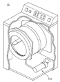
도 1은 본 발명의 일 실시예에 의한 회전 필터링 어셈블리가 적용된 세탁기의 투명 사시도이고,
도 2는 본 발명의 일 실시예들에 의한 회전 필터링 어셈블리의 분해 사시도이고,
도 3 내지 도 5는 본 발명의 다양한 실시예들에 의한 회전 필터링 어셈블리의 회전 임펠러 유닛의 일부를 나타내는 도면들이고,
도 6은 본 발명의 일 실시예에 의한 회전 필터링 어셈블리에 세척수가 유입되는 모습을 나타내는 도면들이고,
도 7은 본 발명의 일 실시예에 의한 회전 필터링 어셈블리의 단면도이다.1 is a transparent perspective view of a washing machine to which a rotary filtering assembly according to an embodiment of the present invention is applied;
2 is an exploded perspective view of a rotary filtering assembly according to an embodiment of the present invention;
3 to 5 are views showing a part of a rotary impeller unit of a rotary filtering assembly according to various embodiments of the present invention,
6 are views showing how washing water flows into the rotary filtering assembly according to an embodiment of the present invention;
7 is a cross-sectional view of a rotary filtering assembly according to one embodiment of the present invention.
이하, 본 발명의 일 실시예를 첨부된 도면을 참조하여 상세하게 설명하기로 한다.Hereinafter, an embodiment of the present invention will be described in detail with reference to the accompanying drawings.
각 도면의 구성요소들에 참조부호를 부가함에 있어서, 동일한 구성요소들에 대해서는 비록 다른 도면상에 표시되더라도 가능한 한 동일한 부호를 가지도록 하고 있음에 유의해야 한다. 또한, 본 발명의 실시예를 설명함에 있어, 관련된 공지 구성 또는 기능에 대한 구체적인 설명이 본 발명의 실시예에 대한 이해를 방해한다고 판단되는 경우에는 그 상세한 설명은 생략한다.In adding reference numerals to components of each drawing, it should be noted that the same components have the same numerals as much as possible even if they are displayed on different drawings. In addition, in describing an embodiment of the present invention, if it is determined that a detailed description of a related known configuration or function hinders understanding of the embodiment of the present invention, the detailed description will be omitted.
본 발명의 실시예의 구성요소를 설명하는 데 있어서, 제1, 제2, A, B, (a), (b) 등의 용어를 사용할 수 있다. 이러한 용어는 그 구성요소를 다른 구성요소와 구별하기 위한 것일 뿐, 그 용어에 의해 해당 구성요소의 본질이나 차례 또는 순서 등이 한정되지 않는다. 또한, 다르게 정의되지 않는 한, 기술적이거나 과학적인 용어를 포함해서 여기서 사용되는 모든 용어들은 본 발명이 속하는 기술분야에서 통상의 지식을 가진 자에 의해 일반적으로 이해되는 것과 동일한 의미를 가진다. 일반적으로 사용되는 사전에 정의되어 있는 것과 같은 용어들은 관련 기술의 문맥상 가지는 의미와 일치하는 의미를 가진 것으로 해석되어야 하며, 본 출원에서 명백하게 정의하지 않는 한, 이상적이거나 과도하게 형식적인 의미로 해석되지 않는다.In describing the components of the embodiment of the present invention, terms such as first, second, A, B, (a), and (b) may be used. These terms are only used to distinguish the component from other components, and the nature, sequence, or order of the corresponding component is not limited by the term. In addition, unless defined otherwise, all terms used herein, including technical or scientific terms, have the same meaning as commonly understood by a person of ordinary skill in the art to which the present invention belongs. Terms such as those defined in commonly used dictionaries should be interpreted as having a meaning consistent with the meaning in the context of the related art, and unless explicitly defined in the present application, they should not be interpreted in an ideal or excessively formal meaning. don't
이하에서 설명하는 유입부와 배출부는 회전 필터링 어셈블리에서 유동하는 유체가 최초 유입되고 최종적으로 배출되는 부위, 즉 홀(hole)을 의미할 수 있다.An inlet and an outlet described below may refer to a part where fluid flowing in the rotary filtering assembly is first introduced and finally discharged, that is, a hole.
전술한 바와 같이, 의류 세탁기의 경우에 장시간 사용시에 섬유 소재의 의류에서 배출되는 대부분의 미세 플라스틱 등이 배출 부위에 장착되는 여과 필터에 적층될 수 있다. 이에 본 발명에서는 상기 여과필터의 근접 부위에 이러한 미세 플라스틱 등의 이물질을 용이하게 제거하기 위한 회전 필러링 구조를 제공하여 여과필터의 수명을 향상시켜 보다 효과적인 여과가 가능하도록 한다는 점에 특징이 있다.As described above, in the case of a clothes washing machine, when used for a long time, most of the microplastics discharged from textile clothes may be laminated to a filter mounted on the discharge portion. Accordingly, the present invention is characterized in that a rotary filtering structure for easily removing foreign substances such as microplastics is provided in the vicinity of the filter to improve the lifespan of the filter and enable more effective filtration.
도 1은 본 발명의 일 실시예에 의한 회전 필터링 어셈블리가 적용된 세탁기의 투명 사시도이고, 도 2는 본 발명의 일 실시예들에 의한 회전 필터링 어셈블리의 분해 사시도이고, 도 3 내지 도 5는 본 발명의 다양한 실시예들에 의한 회전 필터링 어셈블리의 회전 임펠러 유닛의 일부를 나타내는 도면들이다.1 is a transparent perspective view of a washing machine to which a rotary filtering assembly according to an embodiment of the present invention is applied, FIG. 2 is an exploded perspective view of a rotary filtering assembly according to an embodiment of the present invention, and FIGS. 3 to 5 are views of the present invention. are drawings showing a portion of a rotating impeller unit of a rotating filtering assembly according to various embodiments of
이들 도면을 참조하면, 본 발명에 따른 회전 필터링 어셈블리(100)는 세탁기(10)의 내측 및 외측은 물론 세탁기(10)의 전면, 측면, 배면 상측 또는 하측 부위에 별도의 제약없이 선택적으로 배치될 수 있고, 외부로부터 세척수가 유입된 후에 여과되어 배출되도록 유입부(101)와 배출부(102)가 형성되는 필터 하우징 본체(110), 상기 필터 하우징 본체(110)의 내부에 배치되는 필터부(F) 및 상기 필터 하우징 본체(110)의 중심축에 회전 가능하게 결합되고 복수의 플렌지부(210, 310)가 형성되는 회전 임펠러 유닛(200, 300)을 포함하여 구성되어 있다.Referring to these drawings, the
회전 필터링 어셈블리(100)는 세탁기(10)의 세탁조(미도시)로부터 세척이 완료되고 배출되는 상기 세척수가 유동하는 경로, 즉 배수호스 경로상에 형성될 수 있다. 상기 호스는 상기 세탁조로부터 연장되어 본 발명에 따른 회전 필터링 어셈블리(100)를 경유하여 세탁기(10)의 일면에 형성되는 배출구(미도시)를 통하여 외부로 배출될 수 있다.The
회전 필터링 어셈블리(100)는 외형을 이루는 필터 하우징 본체(110)를 포함하고, 필터 하우징 본체(100)는 상기 세척수가 유입되어 여과되도록 내부 공간이 형성되는 원통형으로 형성되어 있다. 필터 하우징 본체(110)의 상측에는 상기 세척수가 유입 가능하도록 유입부(101)가 중심 또는 편심되어 형성되어 있다. 유입부(101)는 상기 세척수가 용이하게 유입되도록 홀(hole) 형상으로 형성되어 있다. 경우에 따라, 상기 필터 하우징 본체(110)에는 상측 부위 및 하측 측면 부위에도 유입부(101) 및 배출부(102)가 각각 추가적으로 형성될 수 있다 이러한 유입부(101)와 배출부(102)의 형성 위치 및 형성 개수는 특별히 제한되지 않음은 물론이다.The
또, 경우에 따라, 필터 하우징 본체(110)의 유입부(101)는 별도의 독립적으로 탈부착이 가능할 수 있다. 마찬가지로, 필터 하우징 본체(110)의 하측에는 상기 세척수가 용이하게 배출되도록 홀(hole) 형상으로 형성되어 있고, 배출부(102)는 별도로 독립적으로 탈부착이 가능할 수 있다.Also, in some cases, the
회전 필터링 어셈블리(100)의 필터부(F)는 회전 필터링 어셈블리(100)의 외형을 이루는 필터 하우징 본체(110)의 내부에 삽입될 수 있다. 즉, 필터부(F)는 유입부(101)와 배출부(102)를 제외하고 필터 하우징 본체(110)의 내부면을 따라 배치될 수 있다. 따라서, 상기 세척수는 회전 필터링 어셈블리(100)의 필터 하우징 본체(110)의 내부로 유입된 후에 필터부(F)의 내부 및 외부를 통하여 여과되어 용이하게 배출될 수 있다. 이러한 필터부(F)는 예를 들어, 시트 형상을 원통형 형상으로 구현하기 위하여 양말단을 핫멜트 접착, 열 접착 등의 방법으로 접착하여 형성될 수 있다. 또는 인서트 사출성형 방식으로 형성될 수도 있음은 물론이다. 필터부(F)는 필터 하우징 본체(110)의 형상에 따라 변형이 가능하고, 예를 들어 원통형 이외에도 단면이 삼각형, 사각형 또는 다각형 형상으로도 형성될 수 있다.The filter unit F of the
본 발명에 따르면, 필터부(F)는 상기 세척수에 포함되는 이물질, 예를 들어 섬유에서 다량 배출되는 미세 플라스틱 등을 여과할 수 있다. 필터부(F)는 세탁기(10)으로부터 탈부착이 가능한 독립적인 구성으로 제공될 수 있다. 따라서, 사용자가 필터부(F)의 사용 기간 등에 따른 교체가 필요한 경우에 용이하게 교체하여 사용할 수 있다.According to the present invention, the filter unit (F) can filter foreign substances included in the washing water, for example, microplastics discharged in large quantities from fibers. The filter unit F may be provided as an independent structure that is detachable from the
바람직하게는 필터부(F)는 미세 치수가 5 mm 미만의 미세입자까지 여과가 가능한 구조로 형성될 수 있다. 경우에 따라서, 상기 필터부는 미세 치수가 초미세플라스틱 입자의 여과가 가능한 0.1㎛ 이하의 입자를 여과되도록 구성될 수 있다. 하나의 예에서, 필터부(F)는 직물, 플라스틱, SUS 또는 금속 등의 시트 소재의 단일 또는 2중 이상으로 적층된 형태의 메쉬망 형상 또는 튜브 또는 원통형으로 형성되는 부직포로 제공될 수 있다. 이러한 필터부(F)는 상기 세척수로 여과되는 미세 섬유입자가 포집될 수 있는 형상이나 소재이면 특별히 한정되는 것은 아님은 물론이다.Preferably, the filter part (F) may be formed in a structure capable of filtering fine particles having a fine size of less than 5 mm. In some cases, the filter unit may be configured to filter particles of 0.1 μm or less capable of filtering ultra-fine plastic particles. In one example, the filter unit (F) may be provided in a non-woven fabric formed in a mesh net shape or a tube or cylindrical shape in the form of a single or double or more laminated sheet material such as fabric, plastic, SUS or metal. Of course, this filter unit (F) is not particularly limited as long as it is a shape or material capable of collecting the fine fiber particles filtered by the washing water.
하나의 예에서, 필터부(F)는 카본블럭필터와, 상기 카본블럭필터의 외주면을 감싸는 형태로 배치되는 나노정전시트 및 UF 시트로 형성될 수 있다. 상기 카본블럭필터는 활성탄, 바인더 및 첨가제를 포함할 수 있다. 상기 나노정전시트는 유리섬유, 셀룰로오스, 알루미나 파이버, 폴리프로필렌(PP) 및 폴리에틸렌(PE)을 포함할 수 있고, 상기 UF 시트는 폴리설폰(PSF), 폴리에테르설폰(PES) 및 폴리비닐리덴디플루오리드(PVDF), 폴리프로필렌(PP) 및 폴리에틸렌(PE)을 포함할 수 있다.In one example, the filter unit (F) may be formed of a carbon block filter, a nano-static sheet and a UF sheet disposed in a form surrounding an outer circumferential surface of the carbon block filter. The carbon block filter may include activated carbon, a binder, and an additive. The nanoelectrostatic sheet may include glass fiber, cellulose, alumina fiber, polypropylene (PP) and polyethylene (PE), and the UF sheet may include polysulfone (PSF), polyethersulfone (PES) and polyvinylidene Fluoride (PVDF), polypropylene (PP) and polyethylene (PE).
경우에 따라서, 상기 필터부(F)에는 바이패스관(미도시)이 형성될 수도 있다. 따라서, 필터부(F)에 이물질 등이 적층되어 필터가 막히는 경우에 상기 바이패스관을 통하여 필터부(F)를 경유하지 않고 배출되도록 할 수 있다.In some cases, a bypass pipe (not shown) may be formed in the filter part (F). Therefore, when the filter is clogged due to accumulation of foreign substances in the filter unit F, it is possible to discharge the filter unit F through the bypass pipe without passing through the filter unit F.
한편, 본 발명에 따른 회전 임펠러 유닛(200, 300)은 필터 하우징 본체(110)의 회전 중심축(C)에 회전 가능하도록 배치되어 있다. 회전 중심축(C)은 필터 하우징 본체(110)의 중심부를 관통하여 수직 방향으로 배치되어 있다. Meanwhile, the
회전 임펠러 유닛(200, 300)은 상기 필터 하우징 본체(110)의 회전 중심축(C)이 삽입되어 연동되어 회전 가능하도록 중공형의 중심축에 회전축 삽입홀(H)이 형성되어 있다. 여기서, 상기 중심축에는 외주 방향으로 소정의 길이로 연장되는 복수의 플렌지부(210, 310)가 형성되어 있다. 즉, 상기 복수의 플렌지부(210, 310)는, 도 7에 도시된 바와 같이, 상기 필터 하우징 본체(110)의 장축 방향('L' 방향)으로 연장되는 형상으로 형성될 수 있다.The
여기서, 복수의 플렌지부(210, 310) 일측 단부는 필터부(F)의 외주면과 소정의 간격으로 이격되도록 배치될 수 있다. 이는 복수의 플렌지부(210, 310)의 회전 동작시에 필터부(F)의 접촉에 의한 마모 등의 손상을 최소화할 수 있다. 경우에 따라서, 임펠러 유닛(200, 300)의 일측 단부는 필터 하우징 본체(110)의 내주면과 상호 일부 또는 전부가 접촉하는 형상으로 배치되도록 할 수도 있다.Here, one end of the plurality of
구체적으로, 회전 임펠러 유닛(200, 300)의 플렌지부(210, 310)는 상기 중심축을 기준으로 방사형으로 소정의 간격으로 배치될 수 있다. 경우에 따라, 회전 임펠러 유닛(200, 300)의 플렌지부(210, 310)의 단부에는 복수의 브러쉬(도 5: 105 참조)가 형성될 수 있다. 이러한 브러쉬(도 5: 105 참조)는 소정의 탄성력으로 형상 변형 후 형상 회복이 가능한 소재이면 특별히 한정되는 것은 아니다.Specifically, the
회전 임펠러 유닛(200, 300)의 플렌지부(210, 310)는, 도 3 및 도 4에 도시된 바와 같이, 상기 중심축으로부터 일측 방향으로 선형 또는 소정의 곡률로 만곡되는 형상으로 형성될 수 있다.As shown in FIGS. 3 and 4 , the
먼저 회전 임펠러 유닛(200)의 플렌지부(210)는, 도 3에 도시된 바와 같이, 상기 중심축을 따라 길이 방향으로 형성되어 있다. 플렌지부(210)는 상기 중심축을 기준으로 4개가 소정의 간격으로 연장되어 방사형으로 형성되어 있다. 이때, 플렌지부(210)는, 측면상 및 평면상 소정의 곡률로 만곡되는 형상으로 형성되어 있다. 플렌지부(210)의 단부에는 복수의 브러쉬(도 5: 105 참조)가 형성될 수 있다.First, the
또, 회전 임펠러 유닛(300)의 플렌지부(310)는, 도 4에 도시된 바와 같이, 상기 필터 하우징 본체(110)의 회전 중심축(C)의 상측 부위에 형성되어 있다. 플렌지부(310)는 상기 중심축을 기준으로 12개가 소정의 간격으로 연장되어 방사형으로 형성되어 있다. 이 때, 플렌지부(310)는 평면상 소정의 길이를 갖고 선형으로 연장되어 형성될 수 있다. 마찬가지로, 플렌지부(310)의 단부에는 복수의 브러쉬(도 5: 105 참조)가 형성될 수 있다.In addition, as shown in FIG. 4 , the
경우에 따라, 회전 임펠러 유닛(300)의 플렌지부(310)는 필터 하우징 본체(110)의 회전 중심축(C)을 기준으로 상측에서 하측 방향으로 소정의 간격으로 복수 개가 형성될 수 있음은 물론이다. 구체적인 예에서, 회전 임펠러 유닛(300)의 플렌지부(310)가 복수 개 구비되는 경우에는 회전 중심축(C)을 기준으로 우측 또는 좌측 부위에만 교번하여 형성되도록 구성될 수도 있다. 즉, 필터 하우징 본체(110)의 내부에서 최상단 부위에 배치되는 회전 임펠러 유닛(300)의 플렌지부(310)는 상기 중심축을 기준으로 우측으로 6개만 형성되고, 하측 부위에 인접 배치되는 또 다른 회전 임펠러 유닛(300)의 플렌지부(310)는 상기 중심축을 기준으로 좌측에만 6개만 형성되는 구조로 형성될 수 있다. 따라서, 필터 하우징 본체(110) 내부로 유입되는 상기 세척수의 유동을 방해하지 않으면서도 여과효과를 유지할 수 있도록 할 수 있다. 회전 임펠러 유닛(300)의 플렌지부(310)의 형상, 개수, 형성위치 등은 사용환경에 따라 적절히 변형 또는 변경 가능함은 물론이다.In some cases, a plurality of
경우에 따라, 본 발명에 따른 회전 필터링 어셈블리(100)에는 회전 임펠러 유닛(200, 300)에 회전력을 전달하는 모터부(미도시) 및 회전 임펠러 유닛(200, 300)에 의하여 배출되는 스케일 등이 보관되는 채집망이 추가로 형성될 수 있다. 이 때, 상기 모터부는, 세척수가 유입되는 동안에만 동작 가능하도록, 별도의 감지센서(미도시)에 의하여 회전 임펠러 유닛(200, 300)의 회전 동작이 제어될 수 있다.In some cases, the
이하, 전술한 본 발명에 따른 회전 필터링 어셈블리(100)에 의하여 여과되는 과정을 첨부된 도면과 함께 설명하면, 도 5는 본 발명의 일 실시예에 의한 회전 필터링 어셈블리에 세척수가 유입되는 모습을 나타내는 도면들이고, 도 6은 본 발명의 일 실시예에 의한 회전 필터링 어셈블리의 단면도들이다.Hereinafter, the filtering process by the
이들 도면을 도 1 내지 4와 함께 참조하면, 먼저 세탁기(10)의 세탁조에 세척수가 공급된다. 투입되는 상기 세척수는 의류 등의 세정이 완료된 후에 배관 또는 호스를 통하여 세탁기(10)의 외부로 배출된다. 상기 세탁조에서 배출되는 상기 세척수는 세탁기(10)의 내측 하부에 형성되는 본 발명에 따른 회전 필터링 어셈블리(100)로 유입되며 외부로 배출되기 전에 여과된다. 이때, 회전 필터링 어셈블리(100)에는 전술한 회전 임펠러 유닛(200, 300)이 배치되어 있으므로, 상기 세척조에서 배출된 후에 유입되는 상기 세척수는 필터부(F)를 경유하며 미세한 섬유 플라스틱이 여과될 수 있게 된다.Referring to these drawings together with FIGS. 1 to 4 , first, washing water is supplied to the washing tub of the
즉, 회전 필터링 어셈블리(100)의 필터 하우징 본체(110) 상측에 형성되는 유입부(101)를 통하여 상기 세척수가 세척조로부터 배출된 후 유입된다. 유입된 상기 세척수는 필터 하우징 본체(110)의 내부에 형성되는 미세 플라스틱의 여과가 가능한 필터부(F)를 통과하며 필터링된 후에 필터 하우징 본체(110) 하측에 형성되는 배출부(102)를 통하여 외부로 배출되게 된다.That is, the washing water is discharged from the washing tank and then introduced through the
이 경우, 필터부(F)의 내측면 및 외측면 부위에는 상기 세척수에서 용출되는 미세한 섬유 플라스틱이 축적되어 스케일(scale)이 형성될 수 있다. 이때, 도 5에 도시된 바와 같이, 회전 필터링 어셈블리(100)의 회전 임펠러 유닛(200, 300)이 자동 또는 수동으로 회전되면서 회전 임펠러 유닛(200, 300)의 플렌지부(210, 310)에 의하여 상기 필터부(F)에 축적된 상기 스케일 등의 이물질이 용이하게 제거될 수 있다. 전술한 회전 임펠러 유닛(200, 300)의 플렌지부(210, 310)에 형성되는 복수의 브러쉬(105)에 의하여 필터부(F)의 손상을 최소화하면서 스케일 등의 제거가 용이하게 이루어질 수 있게 된다.In this case, scale may be formed on the inner and outer surfaces of the filter unit F by accumulating fine plastic fibers eluted from the washing water. At this time, as shown in FIG. 5, the
이러한 구성에 따라, 본 발명에 따른 회전 필터링 어셈블리(100)가 적용된 세탁기는, 상기 세탁조에서 배출되는 상기 세척수의 유체의 충돌에 의하여 회전 임펠러 유닛(200, 300)의 회전이 가능하도록 할 수 있다. 즉, 회전 필터링 어셈블리(100)의 필터 하우징 본체(110) 상측 중앙부위에 형성되는 유입부(101)로 세척수가 유입되게 되면 유입부(101)의 하측 인접 부위에 배치된 회전 임펠러 유닛(200, 300)의 플렌지부(210, 310)가 상기 세척수의 유속에 의하여 자동으로 회전도록 함으로써 상기 세척수의 유속에 따라 회전이 조절되면서 효과적으로 스케일 등의 제거가 이루어질 수 있다. According to this configuration, in the washing machine to which the
이상, 본 발명의 일 실시예를 첨부된 도면을 참조하여 상세하게 설명하였다. 그러나, 본 발명의 실시예가 반드시 상술한 일 실시예에 의하여 한정되는 것은 아니고, 본 발명이 속하는 기술분야에서 통상의 지식을 가진 자에 의한 다양한 변형 및 균등한 범위에서의 실시가 가능함은 당연하다고 할 것이다. 그러므로, 본 발명의 진정한 권리범위는 후술하는 청구범위에 의하여 정해진다고 할 것이다.In the above, an embodiment of the present invention has been described in detail with reference to the accompanying drawings. However, it should be taken for granted that the embodiments of the present invention are not necessarily limited by the above-described embodiment, and various modifications and implementation within the equivalent range are possible by those skilled in the art to which the present invention belongs. will be. Therefore, it will be said that the true scope of the present invention is determined by the claims described later.
100: 회전 필터링 어셈블리
101: 유입부
102: 배출부
105: 브러쉬
110: 필터 하우징 본체
200, 300: 회전 임펠러 유닛
C: 회전 중심축
H: 회전축 삽입홀
F: 필터부100: rotary filtering assembly 101: inlet
102: discharge unit 105: brush
110: filter
C: rotation center axis H: rotation axis insertion hole
F: filter part
Claims (16)
상기 필터 하우징 본체의 내부에 배치되는 필터부; 및
상기 필터 하우징 본체의 중심축에 회전 가능하게 결합되고 적어도 하나의 플렌지부가 형성되는 적어도 하나의 회전 임펠러 유닛;을 포함하는, 회전 필터링 어셈블리.
A filter housing body having an inlet and an outlet so that washing water is filtered and discharged after being introduced from the outside;
a filter unit disposed inside the filter housing body; and
At least one rotary impeller unit rotatably coupled to the central axis of the filter housing body and having at least one flange portion formed therein; including, a rotary filtering assembly.
상기 필터 하우징은 중공형의 원통형 또는 다각형으로 형성되고, 상기 회전 임펠러는 상기 필터 하우징의 상기 유입구 및 배출구 중 적어도 하나의 인접한 부위에 형성되는, 회전 필터링 어셈블리.
According to claim 1,
The filter housing is formed in a hollow cylinder or polygonal shape, and the rotary impeller is formed adjacent to at least one of the inlet and outlet of the filter housing.
상기 회전 임펠러의 플렌지부는 상기 회전 중심축을 기준으로 외측 방향으로 방사상으로 연장되는 형상으로 형성되는, 회전 필터링 어셈블리.
According to claim 1,
The rotational filtering assembly of the rotational filtering assembly, the flange portion of the rotational impeller is formed in a shape extending radially outward with respect to the rotational central axis.
상기 플렌지부의 단부에는 소정의 탄성력으로 형상 변형이 가능한 적어도 하나의 브러쉬(brush)가 형성되어 있는 구조를 포함하는, 회전 필터링 어셈블리.
According to claim 1,
A rotational filtering assembly comprising a structure in which at least one brush capable of shape deformation with a predetermined elastic force is formed at an end of the flange portion.
상기 회전 임펠러의 플렌지부의 일측 단부와 상기 필터부의 외측면은 상호 소정의 거리로 이격되는 간격이 형성되고,
상기 회전 임펠러의 회전에 의하여 상기 브러쉬가 상기 필터부의 외부에 적층되는 이물질을 제거하는 구조를 포함하는, 회전 필터링 어셈블리.
According to claim 4,
A gap is formed between one end of the flange part of the rotary impeller and the outer surface of the filter part by a predetermined distance from each other,
A rotational filtering assembly comprising a structure in which the brush removes foreign substances stacked on the outside of the filter unit by rotation of the rotational impeller.
상기 회전 임펠러의 플렌지부의 외주면은 상기 회전 중심축 방향으로 소정의 곡률을 가지고 만곡되게 형성되는 구조를 포함하는, 회전 필터링 어셈블리.
According to claim 1,
A rotational filtering assembly comprising a structure in which an outer circumferential surface of the flange portion of the rotational impeller is formed to be curved with a predetermined curvature in the direction of the rotational central axis.
상기 회전 임펠러의 플렌지부 상기 회전 중심축으로부터 외주 방향으로 스크류 형상으로 연장되는 구조를 포함하는, 회전 필터링 어셈블리.
According to claim 1,
A rotational filtering assembly comprising a structure extending in a screw shape in an outer circumferential direction from the rotational central axis of the flange portion of the rotational impeller.
상기 회전 임펠러의 플렌지부의 외주면은 상기 회전 중심축 방향으로 선형으로 형성되는 구조를 포함하는, 회전 필터링 어셈블리.
According to claim 1,
The rotational filtering assembly comprising a structure in which an outer circumferential surface of the flange portion of the rotational impeller is formed linearly in the direction of the rotational central axis.
상기 필터 하우징 본체의 하단부는 상기 세척수가 용이하게 배출되도록 소정의 경사를 갖고 하향 경사지게 형성되는 구조를 포함하는, 회전 필터링 어셈블리.
According to claim 1,
The rotary filtering assembly comprising a structure in which the lower end of the filter housing body has a predetermined slope and is formed to be inclined downward so that the washing water is easily discharged.
상기 회전 임펠러는 상기 세척수의 물리적 접촉에 의하여 회전 가능하게 형성되는, 회전 필터링 어셈블리.
According to claim 1,
The rotational filtering assembly, wherein the rotational impeller is rotatably formed by physical contact with the washing water.
상기 필터부는 직물, 플라스틱, SUS 또는 금속의 시트 소재로 형성되고, 메쉬(mesh) 구조를 포함하는, 회전 필터링 어셈블리.
According to claim 1,
The filter unit is formed of a sheet material of fabric, plastic, SUS or metal, and includes a mesh structure, a rotary filtering assembly.
상기 필터부는 미세 치수가 5mm 미만의 미세입자의 여과가 가능한 구조로 형성되는, 회전 필터링 어셈블리.
According to claim 1,
The filter unit is formed of a structure capable of filtering fine particles having a fine dimension of less than 5 mm, a rotary filtering assembly.
상기 회전 임펠러의 플렌지부는 상기 필터 하우징 본체의 장축 길이 방향('L' 방향)으로 소정의 길이로 연장되는 구조를 포함하는, 회전 필터링 어셈블리.
According to claim 1,
The rotary filtering assembly comprising a structure in which the flange portion of the rotary impeller extends to a predetermined length in a longitudinal direction ('L' direction) of the filter housing body.
상기 필터부의 일측에는 상기 세척수를 유도하는 바이패스관(bypass)이 형성되는, 회전 필터링 어셈블리.
According to claim 1,
A rotary filtering assembly, wherein a bypass pipe guiding the washing water is formed at one side of the filter unit.
상기 회전 임펠러 유닛에 회전력을 전달하는 모터; 및
상기 회전 임펠러 유닛에 의하여 배출되는 스케일이 포집되는 채집망;을 더 포함하는, 회전 필터링 어셈블리.
According to claim 1,
a motor that transmits rotational force to the rotational impeller unit; and
A rotational filtering assembly further comprising a; collection net for collecting the scale discharged by the rotational impeller unit.
A washing machine comprising the rotary filtering assembly according to any one of claims 1 to 15.
Priority Applications (3)
| Application Number | Priority Date | Filing Date | Title |
|---|---|---|---|
| KR1020220065785A KR20220156473A (en) | 2022-05-30 | 2022-05-30 | Rotational filtering assembly and wasing machine including the same |
| PCT/KR2022/020424 WO2023234507A1 (en) | 2022-05-30 | 2022-12-15 | Rotary filtering assembly and washing machine comprising same |
| EP22926333.0A EP4306706A1 (en) | 2022-05-30 | 2022-12-15 | Rotary filtering assembly and washing machine comprising same |
Applications Claiming Priority (1)
| Application Number | Priority Date | Filing Date | Title |
|---|---|---|---|
| KR1020220065785A KR20220156473A (en) | 2022-05-30 | 2022-05-30 | Rotational filtering assembly and wasing machine including the same |
Publications (1)
| Publication Number | Publication Date |
|---|---|
| KR20220156473A true KR20220156473A (en) | 2022-11-25 |
Family
ID=84237214
Family Applications (1)
| Application Number | Title | Priority Date | Filing Date |
|---|---|---|---|
| KR1020220065785A KR20220156473A (en) | 2022-05-30 | 2022-05-30 | Rotational filtering assembly and wasing machine including the same |
Country Status (3)
| Country | Link |
|---|---|
| EP (1) | EP4306706A1 (en) |
| KR (1) | KR20220156473A (en) |
| WO (1) | WO2023234507A1 (en) |
Cited By (2)
| Publication number | Priority date | Publication date | Assignee | Title |
|---|---|---|---|---|
| CN113699751A (en) * | 2020-05-21 | 2021-11-26 | 青岛海尔洗衣机有限公司 | Washing machine |
| WO2023234507A1 (en) * | 2022-05-30 | 2023-12-07 | 주식회사 마이크로필터 | Rotary filtering assembly and washing machine comprising same |
Citations (1)
| Publication number | Priority date | Publication date | Assignee | Title |
|---|---|---|---|---|
| KR102179793B1 (en) | 2019-03-27 | 2020-11-17 | 이화여자대학교 산학협력단 | Appratus for filtering drainage of washing machine |
Family Cites Families (6)
| Publication number | Priority date | Publication date | Assignee | Title |
|---|---|---|---|---|
| KR200146593Y1 (en) * | 1996-09-30 | 1999-06-15 | 전주범 | The filter apparatus of a washing machine |
| JP4945396B2 (en) * | 2007-10-10 | 2012-06-06 | シャープ株式会社 | Drum washing machine |
| CN106567230B (en) * | 2015-10-09 | 2021-03-16 | 青岛海尔洗涤电器有限公司 | Drainage filter and washing machine |
| WO2019122862A1 (en) * | 2017-12-19 | 2019-06-27 | Xeros Limited | Filter for a treatment apparatus |
| KR102143759B1 (en) * | 2019-01-07 | 2020-08-12 | 양형학 | Dyeing Solution Filtering Device and Dyeing Machine |
| KR20220156473A (en) * | 2022-05-30 | 2022-11-25 | 주식회사 마이크로필터 | Rotational filtering assembly and wasing machine including the same |
-
2022
- 2022-05-30 KR KR1020220065785A patent/KR20220156473A/en unknown
- 2022-12-15 EP EP22926333.0A patent/EP4306706A1/en active Pending
- 2022-12-15 WO PCT/KR2022/020424 patent/WO2023234507A1/en unknown
Patent Citations (1)
| Publication number | Priority date | Publication date | Assignee | Title |
|---|---|---|---|---|
| KR102179793B1 (en) | 2019-03-27 | 2020-11-17 | 이화여자대학교 산학협력단 | Appratus for filtering drainage of washing machine |
Cited By (2)
| Publication number | Priority date | Publication date | Assignee | Title |
|---|---|---|---|---|
| CN113699751A (en) * | 2020-05-21 | 2021-11-26 | 青岛海尔洗衣机有限公司 | Washing machine |
| WO2023234507A1 (en) * | 2022-05-30 | 2023-12-07 | 주식회사 마이크로필터 | Rotary filtering assembly and washing machine comprising same |
Also Published As
| Publication number | Publication date |
|---|---|
| WO2023234507A1 (en) | 2023-12-07 |
| EP4306706A1 (en) | 2024-01-17 |
Similar Documents
| Publication | Publication Date | Title |
|---|---|---|
| EP4306706A1 (en) | Rotary filtering assembly and washing machine comprising same | |
| EP1645674B1 (en) | Washing machine and method of controlling the same | |
| US7707858B2 (en) | Washing machine and lint removing apparatus thereof | |
| JP5799200B2 (en) | Drum washing machine | |
| CN102395727B (en) | Condensation dryer having filter device | |
| JP4059236B2 (en) | Drum type washer / dryer | |
| US6402962B1 (en) | Self-cleaning filter with bypass | |
| CN111655923A (en) | Method for operating a washing machine and washing machine | |
| KR101332286B1 (en) | Washing Machine | |
| AU2007240254A1 (en) | Laundry machine | |
| EP3135805B1 (en) | Laundry dryer | |
| KR100921459B1 (en) | Steam laundry dryer | |
| US11008695B2 (en) | Constructive arrangement applied to the agitator of a laundry washing machine | |
| KR20110063062A (en) | Laundry treatment machine | |
| WO2020046241A2 (en) | A laundry washing and/or drying machine comprising a filter group | |
| EP2719819B1 (en) | Heat pump laundry dryer | |
| JP3898687B2 (en) | Drum type washer / dryer | |
| JP5446901B2 (en) | Drum type washer / dryer | |
| WO2020039770A1 (en) | Washing machine | |
| KR100962364B1 (en) | Dry cleaning apparatus having a separate function of water from cleaning oil | |
| US20180135220A1 (en) | Washing machine | |
| JP4494142B2 (en) | Drum type washer / dryer | |
| KR20230166183A (en) | Filter assembly and washing machine including the same | |
| CN216998976U (en) | Clothes nursing machine | |
| KR102389596B1 (en) | washing machine having a lint collecting device |
Legal Events
| Date | Code | Title | Description |
|---|---|---|---|
| G15R | Request for early publication |