KR20220143778A - Push-pull surgical instrument end effector actuation using flexible tension member - Google Patents
Push-pull surgical instrument end effector actuation using flexible tension member Download PDFInfo
- Publication number
- KR20220143778A KR20220143778A KR1020227035598A KR20227035598A KR20220143778A KR 20220143778 A KR20220143778 A KR 20220143778A KR 1020227035598 A KR1020227035598 A KR 1020227035598A KR 20227035598 A KR20227035598 A KR 20227035598A KR 20220143778 A KR20220143778 A KR 20220143778A
- Authority
- KR
- South Korea
- Prior art keywords
- instrument shaft
- assembly
- actuation rod
- tension member
- actuation
- Prior art date
Links
- 239000012636 effector Substances 0.000 title claims abstract description 80
- 238000000034 method Methods 0.000 claims abstract description 42
- 238000002955 isolation Methods 0.000 claims description 43
- 230000008878 coupling Effects 0.000 claims description 3
- 238000010168 coupling process Methods 0.000 claims description 3
- 238000005859 coupling reaction Methods 0.000 claims description 3
- 238000003780 insertion Methods 0.000 claims description 2
- 230000037431 insertion Effects 0.000 claims description 2
- 238000001356 surgical procedure Methods 0.000 description 19
- 230000013011 mating Effects 0.000 description 10
- 230000007246 mechanism Effects 0.000 description 8
- 238000003384 imaging method Methods 0.000 description 7
- 238000009434 installation Methods 0.000 description 7
- 238000010586 diagram Methods 0.000 description 6
- 238000012986 modification Methods 0.000 description 6
- 230000004048 modification Effects 0.000 description 6
- 230000008569 process Effects 0.000 description 6
- 238000002405 diagnostic procedure Methods 0.000 description 4
- 230000006870 function Effects 0.000 description 4
- 230000014509 gene expression Effects 0.000 description 4
- 238000013519 translation Methods 0.000 description 4
- 210000001015 abdomen Anatomy 0.000 description 2
- 230000000694 effects Effects 0.000 description 2
- 238000001839 endoscopy Methods 0.000 description 2
- 230000002452 interceptive effect Effects 0.000 description 2
- 238000002357 laparoscopic surgery Methods 0.000 description 2
- 238000002324 minimally invasive surgery Methods 0.000 description 2
- 230000008447 perception Effects 0.000 description 2
- 238000011084 recovery Methods 0.000 description 2
- 230000004044 response Effects 0.000 description 2
- 206010028980 Neoplasm Diseases 0.000 description 1
- 210000000683 abdominal cavity Anatomy 0.000 description 1
- 230000002159 abnormal effect Effects 0.000 description 1
- 230000004075 alteration Effects 0.000 description 1
- 210000004204 blood vessel Anatomy 0.000 description 1
- 201000011510 cancer Diseases 0.000 description 1
- 238000004891 communication Methods 0.000 description 1
- 230000000295 complement effect Effects 0.000 description 1
- 238000010276 construction Methods 0.000 description 1
- 238000012937 correction Methods 0.000 description 1
- 238000002574 cystoscopy Methods 0.000 description 1
- 238000011846 endoscopic investigation Methods 0.000 description 1
- 210000001035 gastrointestinal tract Anatomy 0.000 description 1
- 238000012978 minimally invasive surgical procedure Methods 0.000 description 1
- 230000003287 optical effect Effects 0.000 description 1
- 238000012545 processing Methods 0.000 description 1
- 238000002432 robotic surgery Methods 0.000 description 1
- 230000035807 sensation Effects 0.000 description 1
- 230000002792 vascular Effects 0.000 description 1
Images


Classifications
-
- A—HUMAN NECESSITIES
- A61—MEDICAL OR VETERINARY SCIENCE; HYGIENE
- A61B—DIAGNOSIS; SURGERY; IDENTIFICATION
- A61B34/00—Computer-aided surgery; Manipulators or robots specially adapted for use in surgery
- A61B34/70—Manipulators specially adapted for use in surgery
- A61B34/71—Manipulators operated by drive cable mechanisms
-
- A—HUMAN NECESSITIES
- A61—MEDICAL OR VETERINARY SCIENCE; HYGIENE
- A61B—DIAGNOSIS; SURGERY; IDENTIFICATION
- A61B17/00—Surgical instruments, devices or methods, e.g. tourniquets
- A61B17/00234—Surgical instruments, devices or methods, e.g. tourniquets for minimally invasive surgery
-
- A—HUMAN NECESSITIES
- A61—MEDICAL OR VETERINARY SCIENCE; HYGIENE
- A61B—DIAGNOSIS; SURGERY; IDENTIFICATION
- A61B17/00—Surgical instruments, devices or methods, e.g. tourniquets
- A61B17/28—Surgical forceps
- A61B17/29—Forceps for use in minimally invasive surgery
-
- A—HUMAN NECESSITIES
- A61—MEDICAL OR VETERINARY SCIENCE; HYGIENE
- A61B—DIAGNOSIS; SURGERY; IDENTIFICATION
- A61B34/00—Computer-aided surgery; Manipulators or robots specially adapted for use in surgery
- A61B34/30—Surgical robots
-
- A—HUMAN NECESSITIES
- A61—MEDICAL OR VETERINARY SCIENCE; HYGIENE
- A61B—DIAGNOSIS; SURGERY; IDENTIFICATION
- A61B34/00—Computer-aided surgery; Manipulators or robots specially adapted for use in surgery
- A61B34/30—Surgical robots
- A61B34/37—Master-slave robots
-
- A—HUMAN NECESSITIES
- A61—MEDICAL OR VETERINARY SCIENCE; HYGIENE
- A61B—DIAGNOSIS; SURGERY; IDENTIFICATION
- A61B34/00—Computer-aided surgery; Manipulators or robots specially adapted for use in surgery
- A61B34/70—Manipulators specially adapted for use in surgery
-
- A—HUMAN NECESSITIES
- A61—MEDICAL OR VETERINARY SCIENCE; HYGIENE
- A61B—DIAGNOSIS; SURGERY; IDENTIFICATION
- A61B17/00—Surgical instruments, devices or methods, e.g. tourniquets
- A61B17/00234—Surgical instruments, devices or methods, e.g. tourniquets for minimally invasive surgery
- A61B2017/00292—Surgical instruments, devices or methods, e.g. tourniquets for minimally invasive surgery mounted on or guided by flexible, e.g. catheter-like, means
-
- A—HUMAN NECESSITIES
- A61—MEDICAL OR VETERINARY SCIENCE; HYGIENE
- A61B—DIAGNOSIS; SURGERY; IDENTIFICATION
- A61B17/00—Surgical instruments, devices or methods, e.g. tourniquets
- A61B2017/00477—Coupling
-
- A—HUMAN NECESSITIES
- A61—MEDICAL OR VETERINARY SCIENCE; HYGIENE
- A61B—DIAGNOSIS; SURGERY; IDENTIFICATION
- A61B17/00—Surgical instruments, devices or methods, e.g. tourniquets
- A61B17/28—Surgical forceps
- A61B17/29—Forceps for use in minimally invasive surgery
- A61B2017/2901—Details of shaft
- A61B2017/2902—Details of shaft characterized by features of the actuating rod
-
- A—HUMAN NECESSITIES
- A61—MEDICAL OR VETERINARY SCIENCE; HYGIENE
- A61B—DIAGNOSIS; SURGERY; IDENTIFICATION
- A61B17/00—Surgical instruments, devices or methods, e.g. tourniquets
- A61B17/28—Surgical forceps
- A61B17/29—Forceps for use in minimally invasive surgery
- A61B2017/2926—Details of heads or jaws
- A61B2017/2932—Transmission of forces to jaw members
-
- A—HUMAN NECESSITIES
- A61—MEDICAL OR VETERINARY SCIENCE; HYGIENE
- A61B—DIAGNOSIS; SURGERY; IDENTIFICATION
- A61B34/00—Computer-aided surgery; Manipulators or robots specially adapted for use in surgery
- A61B34/30—Surgical robots
- A61B2034/302—Surgical robots specifically adapted for manipulations within body cavities, e.g. within abdominal or thoracic cavities
Abstract
수술 툴 및 관련 방법은 작동 인장 부재를 통해 작동 로드 어셈블리를 관절운동시킨다. 수술 툴은 엔드 이펙터, 엔드 이펙터를 지지하는 기기 샤프트 어셈블리, 엔드 이펙터와 구동 가능하게 연결되는 작동 로드 어셈블리, 가이드 표면, 작동 로드 어셈블리에 연결되는 가요성 인장 부재 및 작동부를 포함한다. 작동 로드 어셈블리는 기기 샤프트 어셈블리 내에서 슬라이딩하도록 장착된다. 가요성 인장 부재는 연결부에서 작동 로드 어셈블리에 연결된다. 가요성 인장 부재는 연결부로부터 원취측으로 가이드 표면까지 연장되고, 가이드 표면 둘레에 권취되고, 가이드 표면으로부터 근위측으로 연장되는 제1 부분을 포함한다. 작동부는 가요성 인장 부재와 구동 가능하게 연결되고, 인장 부재를 관절운동시키도록 작동 가능하여, 작동 로드 어셈블리를 관절운동시켜 엔드 이펙터를 작동시킨다.A surgical tool and related methods articulate an actuating rod assembly via an actuating tension member. The surgical tool includes an end effector, an instrument shaft assembly supporting the end effector, an actuation rod assembly drivably coupled to the end effector, a guide surface, a flexible tension member coupled to the actuation rod assembly, and an actuator. The actuation rod assembly is mounted to slide within the instrument shaft assembly. The flexible tension member is connected to the actuation rod assembly at the connection. The flexible tension member includes a first portion extending distally from the connection portion to the guide surface, wound around the guide surface, and extending proximally from the guide surface. The actuator is drivably connected with the flexible tension member and is operable to articulate the tension member, thereby articulating the actuation rod assembly to actuate the end effector.

Description
관련 출원에 대한 상호 참조CROSS-REFERENCE TO RELATED APPLICATIONS
본 출원은 모든 면에서 그 전체 내용이 여기에 참조되는 2016년 9월 9일자로 출원된 미국 가특허출원 제62/385,642호의 우선권을 주장한다.This application claims priority in all respects to U.S. Provisional Patent Application No. 62/385,642, filed September 9, 2016, the entire contents of which are incorporated herein by reference.
발명의 분야field of invention
본 발명은 대체로 가요성 인장 부재를 이용한 푸시-풀 수술 기기 엔드 이펙터의 작동에 관한 것이다.FIELD OF THE INVENTION The present invention relates generally to operation of a push-pull surgical instrument end effector using a flexible tension member.
최소 침습 수술 기법은 진단 절차 또는 수술 절차 중에 손상되는 무관 조직의 양을 감소시킴으로써 환자의 회복 시간, 불편함 및 유해한 부작용을 감소시키는 데 목적이 있다. 결과적으로, 표준적 수술에 대한 평균 입원 기간이 최소 침습 수술 기법을 사용하여 크게 단축될 수 있다. 또한, 환자의 회복 시간, 환자의 불편함, 수술 부작용 및 업무 이탈 시간도 최소 침습 수술로 감소될 수 있다.Minimally invasive surgical techniques aim to reduce the patient's recovery time, discomfort, and harmful side effects by reducing the amount of irrelevant tissue damaged during diagnostic or surgical procedures. Consequently, the average length of hospital stay for standard surgery can be significantly shortened using minimally invasive surgical techniques. In addition, the recovery time of the patient, the discomfort of the patient, the side effects of the operation, and the departure time can also be reduced with the minimally invasive surgery.
최소 침습 수술의 하나의 일반적인 형태는 내시경술이며, 내시경술의 하나의 일반적인 형태는 복강 내에서의 최소 침습 검사 및 수술인 복강경술이다. 표준적 복강경 수술에 있어서는, 환자의 복부에 가스가 취입되고, 캐뉼라 슬리브가 복강경술 기기의 엔트리 포트를 제공하기 위해 작은(대략 1/2 인치 이하) 절개부를 통과한다.One common form of minimally invasive surgery is endoscopy, and one common form of endoscopy is laparoscopy, which is a minimally invasive examination and surgery in the abdominal cavity. In standard laparoscopic surgery, gas is blown into the patient's abdomen and a cannula sleeve is passed through a small (approximately 1/2 inch or less) incision to provide an entry port for the laparoscopic instrument.
복강경 수술 기기는 일반적으로 수술 영역을 보기 위한 내시경(예를 들어, 복강경) 및 수술 부위에서 작업하기 위한 툴을 포함한다. 이 작업 툴은 일반적으로 각각의 작업 툴의 워킹 엔드 또는 엔드 이펙터가 연장 튜브(예컨대, 기기 샤프트 또는 메인 샤프트로도 알려짐)에 의해 핸들로부터 이격되어 있다는 점을 제외하고는 통상적인(개복) 수술에 사용되는 것과 유사하다. 엔드 이펙터는 예를 들어 클램프, 그래스퍼, 시저, 스테이플러, 소작 툴, 리니어 커터 또는 니들 홀더를 포함할 수 있다.Laparoscopic surgical instruments generally include an endoscope (eg, laparoscope) for viewing the surgical area and tools for working at the surgical site. This working tool is generally used in conventional (open) surgery except that the working end or end effector of each working tool is spaced from the handle by an extension tube (eg, also known as an instrument shaft or main shaft). similar to those used The end effector may include, for example, a clamp, grasper, scissor, stapler, cauterization tool, linear cutter or needle holder.
수술 절차를 수행하기 위해, 외과의는 수술 툴을 캐뉼라 슬리브를 통해 수술 부위에 전달하고, 복부 밖에서 조작한다. 외과의는 내시경으로부터 취득되는 수술 부위의 영상을 표시하는 모니터에서 수술 절차를 본다. 유사한 내시경 기법이 예를 들어 관절경술, 후복막강경술, 골반경술, 신장경술, 방광경술, 뇌조경술, 부비강경술, 자궁경술, 요도경술 등에 채용된다.To perform a surgical procedure, the surgeon delivers a surgical tool through a cannula sleeve to the surgical site and manipulates it outside the abdomen. The surgeon views the surgical procedure on a monitor displaying an image of the surgical site obtained from the endoscope. Similar endoscopic techniques are employed, for example, arthroscopy, retroperitoneal surgery, pelvicoscopy, nephoscopy, cystoscopy, cerebroscopy, sinusoscopy, hysteroscopy, urethoscopy, and the like.
최소 침습 원격 수술 로봇 시스템이 외과의가 원격 위치(무균 영역 외부)에서 환자를 수술하는 것을 가능하게 해줄뿐만 아니라 내부 수술 부위에 작업할 때의 외과의의 조작성을 증가시키도록 개발되고 있다. 원격 수술 시스템에서, 외과의는 흔히 제어 콘솔에서 수술 부위의 영상을 제공받는다. 적합한 뷰어 또는 디스플레이 상의 수술 부위의 3차원 영상을 보면서, 외과의는 제어 콘솔의 마스터 입력 또는 제어 장치를 조작하는 것에 의해 환자에 대한 수술 절차를 수행한다. 각각의 마스터 입력 장치는 서보 기구적으로(servo-mechanically) 작동되는/관절운동되는 수술 기기의 모션을 제어한다. 수술 절차 중에, 원격 수술 시스템은 외과의를 대신해 마스터 입력 장치의 조작에 응답하여 예를 들어 니들을 홀드하거나 구동시키는 기능, 혈관을 파지하는 기능, 조직을 절개하는 기능 등의 다양한 기능을 수행하는 엔드 이펙터를 갖는 다양한 수술 기기 또는 툴의 기계적 작동 및 제어를 제공할 수 있다.Minimally invasive telesurgical robotic systems are being developed to enable surgeons to operate on patients from remote locations (outside the sterile area) as well as increase the surgeon's operability when working with internal surgical sites. In telesurgical systems, the surgeon is often provided with an image of the surgical site at a control console. While viewing a three-dimensional image of the surgical site on a suitable viewer or display, the surgeon performs a surgical procedure on the patient by manipulating the master input or control device of the control console. Each master input device controls the motion of the servo-mechanically actuated/articulated surgical instrument. During a surgical procedure, the remote surgical system is an end effector that performs various functions on behalf of the surgeon, such as a function to hold or drive a needle, a function to grip a blood vessel, a function to cut tissue, etc. in response to manipulation of a master input device. It can provide mechanical operation and control of various surgical instruments or tools with
수술용 클램핑 및 커팅 툴(예컨대, 수술용 스테이플러로도 알려진 비로봇식 선형 클램핑, 스테이플링 및 커팅 장치; 및 전기 수술 혈관 봉합 장치)이 많은 다른 수술 절차에 사용되어 왔다. 예를 들어, 수술용 스테이플러가 위장관에서 암 또는 이상 조직을 절제할 수 있다. 공지된 수술용 스테이플러를 포함하여 다수의 공지된 수술용 클램핑 및 커팅 장치는 클랭핑된 조직을 커팅하기 위해 조직 및 관절형 나이프를 클램핑하는 대향하는 조(opposing jaws)를 갖는다.Surgical clamping and cutting tools (eg, non-robotic linear clamping, stapling, and cutting devices also known as surgical staplers; and electrosurgical vascular closure devices) have been used in many other surgical procedures. For example, a surgical stapler may ablate cancer or abnormal tissue in the gastrointestinal tract. Many known surgical clamping and cutting devices, including known surgical staplers, have opposing jaws for clamping tissue and articulating knives for cutting the clamped tissue.
수술용 클램핑 및 커팅 툴은 교체 가능한 스테이플러 카트리지(stapler cartridge)가 장착되는 기기 샤프트 지지 단부 이펙터를 포함할 수 있다. 엔드 이펙터의 조는 스테이플러 카트리지와 조 사이의 조직을 클램핑하도록 관절운동될 수 있다. 그런 다음 스테이플러 카트리지가 관절운동되어 스테이플러 카트리지로부터 스테이플을 배치시켜 스테이플러 카트리지와 조 사이에 클램핑된 조직을 스테이플링할 수 있다. 스테이플러 카트리지는 배치된 스테이플의 열 사이에서 스테이플링된 조직을 커팅할 수 있도록 커팅하도록 관절운동 가능한 나이프를 포함할 수 있다.The surgical clamping and cutting tool may include an instrument shaft support end effector to which a replaceable stapler cartridge is mounted. The jaws of the end effector may be articulated to clamp tissue between the stapler cartridge and the jaws. The stapler cartridge may then be articulated to place staples from the stapler cartridge to staple the tissue clamped between the stapler cartridge and jaws. The stapler cartridge may include a knife articulated to cut stapled tissue between rows of positioned staples.
조직을 클램핑, 스테이플링 및/또는 커팅하기에 충분한 작동력 레벨은 상당할 수 있다. 또한, 엔드 이펙터를 지지하는 기기 샤프트의 직경을 제한하고, 상기 기기 샤프트를 통해 연장되는 링키지를 통해 엔드 이펙터와 구동 가능하게 연결되는 근위 작동부를 통해 엔드 이펙터를 작동시키는 것이 바람직하다. 또한, 작은 직경의 기기 샤프트를 통해 근위 작동부와 구동 가능하게 연결된 엔드 이펙터까지 연장되는 링키지는 견고하고, 저렴하며, 신뢰성이 있는 것이 바람직하다. 여기에 제시되는 수술 툴 및 관련 방법은 견고하고, 저렴하며, 신뢰할 수 있는 방식으로 비교적 작은 직경의 기기 샤프트를 통해 클램핑, 스테이플링 및 커팅 엔드 이펙터와 같은 엔드 이펙터에 충분한 작동력을 전달하는 데 적합하다.An actuation force level sufficient to clamp, staple, and/or cut tissue may be significant. It is also desirable to limit the diameter of the instrument shaft supporting the end effector and to actuate the end effector through a proximal actuating portion drivably connected to the end effector through a linkage extending through the instrument shaft. Further, it is desirable that a linkage extending through the small diameter instrument shaft to an end effector drivably connected to the proximal actuator is robust, inexpensive, and reliable. The surgical tool and related methods presented herein are suitable for transmitting sufficient actuation force to end effectors such as clamping, stapling and cutting end effectors through relatively small diameter instrument shafts in a robust, inexpensive and reliable manner. .
가요성 인장 부재의 근위측 퇴축(proximal retraction)이 기기 샤프트 어셈블리를 통해 기기 샤프트 어셈블리에 의해 지지되는 엔드 이펙터로 원위 방향의 작동력을 전달하는 데 사용되는 수술 툴 및 관련 방법이 제공된다. 가요성 인장 부재는 기기 샤프트 어셈블리 내에 배치된 가이드 표면 둘레에 권취되고, 가요성 인장 부재의 퇴축에 응답하여 엔드 이펙터를 향해 이동되는 작동 로드 어셈블리에 연결된다. 작동 로드 어셈블리, 가이드 표면, 및 가요성 인장 부재는 기다란 비교적 작은 직경의 기기 샤프트 어셈블리 내에 둘러싸여 클램핑, 스테이플링 및 커팅 엔드 이펙터와 같은 수술 엔드 이펙터를 작동시키기 위한 원위 방향 작동력을 전달하도록 구성된다.A surgical tool and related method are provided wherein proximal retraction of a flexible tension member is used to transmit an actuation force in a distal direction through an instrument shaft assembly to an end effector supported by the instrument shaft assembly. The flexible tension member is wound around a guide surface disposed within the instrument shaft assembly and coupled to an actuation rod assembly that is moved toward the end effector in response to retraction of the flexible tension member. The actuation rod assembly, guide surface, and flexible tension member are enclosed within an elongate, relatively small diameter instrument shaft assembly and configured to transmit a distal actuation force for actuating a surgical end effector, such as a clamping, stapling, and cutting end effector.
따라서, 하나의 양태에 있어서, 수술 툴이 제공된다. 이 수술 툴은 작동부, 엔드 이펙터, 상기 작동부를 상기 엔드 이펙터에 연결시키는 기기 샤프트 어셈블리, 상기 엔드 이펙터와 구동 가능하게 연결되는 작동 로드 어셈블리 및 가요성 인장 부재를 포함한다. 기기 샤프트 어셈블리는 기기 샤프트 축을 따라 기다랗고, 내강(lumen)을 한정한다. 기기 샤프트 어셈블리는 내강의 원위 단부를 향해 배치되는 가이드 표면을 포함한다. 작동 로드 어셈블리는 기기 샤프트 축을 따라 기기 샤프트 어셈블리에 대해 병진운동하도록 내강 내에 슬라이딩 가능하게 장착된다. 가요성 인장 부재는 작동부를 작동 로드 어셈블리에 구동 가능하게 연결시킨다. 가요성 인장 부재는 작동부와 가이드 표면 사이에 길이 방향으로 배치되는 연결부에서 작동 로드 어셈블리에 연결된다. 가요성 인장 부재는 연결부로부터, 원위측으로 가이드 표면을 향해 연장되고, 가이드 표면 둘레로 권취되고, 작동부를 향해 근위측으로 연장되는 제1 부분을 포함한다. 작동부는 작동 로드 어셈블리를 원위 방향으로 병진운동시키기 위해 가요성 인장 부재의 제1 부분의 장력을 증가시키도록 작동 가능하다.Accordingly, in one aspect, a surgical tool is provided. The surgical tool includes an actuator, an end effector, an instrument shaft assembly connecting the actuator to the end effector, an actuating rod assembly drivably connected to the end effector, and a flexible tension member. The instrument shaft assembly is elongated along the instrument shaft axis and defines a lumen. The instrument shaft assembly includes a guide surface disposed toward the distal end of the lumen. The actuation rod assembly is slidably mounted within the lumen for translation relative to the instrument shaft assembly along an instrument shaft axis. The flexible tension member drivably connects the actuator to the actuation rod assembly. The flexible tension member is connected to the actuating rod assembly at a connection disposed longitudinally between the actuating member and the guide surface. The flexible tension member includes a first portion extending distally toward the guide surface from the connection portion, wound around the guide surface, and extending proximally toward the actuation portion. The actuator is operable to increase tension in the first portion of the flexible tension member to translate the actuation rod assembly in a distal direction.
다수의 실시예에서, 작동부는 기기 샤프트 어셈블리를 지지하는 근위 섀시에 대해 기기 샤프트 축선 둘레로 기기 샤프트 어셈블리를 회전시키도록 작동 가능하다. 다수의 실시예에서, 작동 로드 어셈블리는 기기 샤프트 어셈블리와 함께 기기 샤프트 축을 중심으로 회전하도록 구속된다. 수술 툴은 기기 샤프트 축을 따라 연장되는 격리 튜브(isolation tube)를 포함할 수 있다. 격리 튜브는 연결부와 작동부 사이에 배치될 수 있다. 가요성 인장 부재의 제1 및 제2 부분은 격리 튜브를 통과할 수 있다. 격리 튜브는 제1 및 제2 부분의 상호 얽힘 가능한 길이 부분을 둘러싸서 격리 튜브를 에워싸는 내강 영역으로부터 상호 얽힘 가능한 길이 부분을 격리시킬 수 있다. 따라서, 엔드 이펙터를 작동 및/또는 관절운동시키기 위한 하나 이상의 추가적인 작동 부재가 격리 튜브를 에워싸는 내강 영역을 통해 경로지정(routing)될 수 있고, 이에 따라 기기 샤프트 어셈블리의 회전으로 유발되는 제1 및 제2 부분의 상호 얽힘의 결과로써 손상되는 것이 방지될 수 있다.In many embodiments, the actuator is operable to rotate the instrument shaft assembly about an instrument shaft axis relative to a proximal chassis supporting the instrument shaft assembly. In some embodiments, the actuation rod assembly is constrained to rotate about an instrument shaft axis with the instrument shaft assembly. The surgical tool may include an isolation tube extending along an instrument shaft axis. An isolation tube may be disposed between the connecting portion and the actuating portion. The first and second portions of the flexible tension member may pass through the isolation tube. The isolation tube may surround the entangled length portion of the first and second portions to isolate the entangleable length portion from the lumen region surrounding the isolation tube. Accordingly, one or more additional actuating members for actuating and/or articulating the end effector may be routed through the lumen region surrounding the isolating tube, such that the first and second actuation members caused by rotation of the instrument shaft assembly Damage as a result of the entanglement of the two parts can be prevented.
가요성 인장 부재는 임의의 적합한 가요성 인장 부재를 포함할 수 있다. 예를 들어, 가요성 인장 부재는 작동 케이블을 포함할 수 있다. 가요성 인장 부재의 제1 부분은 케이블의 제1 길이 부분을 포함할 수 있고, 가요성 인장 부재의 제2 부분은 케이블의 제2 길이 부분을 포함할 수 있다. 수술 툴은 가이드 표면을 포함하는 풀리를 포함할 수 있다. 작동부는 풀리에 대한 이동의 범위에 걸쳐 작동 로드 어셈블리를 이동시키도록 작동 가능할 수 있다. 작동 로드 어셈블리는 이동의 범위 전체에 걸쳐 풀리를 수용하도록 구성된 슬롯을 포함할 수 있다. 작동 로드 어셈블리는 케이블의 제2 길이 부분이 연장되어 통과하는 케이블 가이드 구멍을 포함할 수 있다.The flexible tension member may include any suitable flexible tension member. For example, the flexible tension member may include an actuation cable. The first portion of the flexible tension member may include a first length portion of the cable and the second portion of the flexible tension member may include a second length portion of the cable. The surgical tool may include a pulley comprising a guide surface. The actuator may be operable to move the actuation rod assembly over a range of motion relative to the pulley. The actuation rod assembly may include a slot configured to receive a pulley throughout its range of motion. The actuation rod assembly may include a cable guide aperture through which a second length portion of the cable extends.
다수의 실시예에서, 기기 샤프트 어셈블리는 작동 로드 어셈블리, 가이드 표면 및 가요성 인장 부재의 기기 샤프트 어셈블리의 내강 내로의 설치를 수용하고, 작동 로드 어셈블리, 안내 표면 및 가요성 인장 부재를 에워싸는 내강을 형성하도록 결합 가능한 개별 구성요소(예를 들어, 개별 상반부 및 하반부)를 포함한다. 예를 들어, 기기 샤프트 어셈블리는 제1 구성요소 및 제2 구성요소를 포함할 수 있다. 제1 및 제2 구성요소는 제1 및 제2 구성요소가 결합해제될 때 작동 로드 어셈블리, 가이드 표면 및 가요성 인장 부재의 내강 내로의 삽입을 수용하도록 구성될 수 있다. 제1 및 제2 구성요소는 결합되어 내강을 형성하도록 구성될 수 있다.In some embodiments, the instrument shaft assembly accommodates installation of the actuation rod assembly, the guide surface, and the flexible tension member into a lumen of the instrument shaft assembly, and defines a lumen surrounding the actuation rod assembly, the guide surface, and the flexible tension member. separate components (eg, separate upper and lower halves) that are engageable to For example, the instrument shaft assembly may include a first component and a second component. The first and second components may be configured to accommodate insertion of the actuation rod assembly, the guide surface, and the flexible tension member into the lumen when the first and second components are disengaged. The first and second components may be configured to be joined to form a lumen.
다수의 실시예에서, 작동부는 안내 표면에 대한 이동의 범위에 걸쳐 작동 로드 어셈블리를 이동시키도록 작동 가능하다. 작동 로드 어셈블리는 제1 방향으로 돌출하는 제1 가이드 피처 및 제1 방향과 상이한 제2 방향으로 돌출하는 제2 가이드 피처를 포함할 수 있다. 제1 구성요소 및 제2 구성요소는 이동의 범위 전체에 걸쳐 제1 가이드 피처를 수용하도록 치수결정된 제1 슬롯 및 제2 가이드 피처를 수용하도록 치수결정된 제2 슬롯을 형성할 수 있다.In many embodiments, the actuator is operable to move the actuation rod assembly over a range of movement relative to the guide surface. The actuation rod assembly may include a first guide feature projecting in a first direction and a second guide feature projecting in a second direction different from the first direction. The first component and the second component may form a first slot sized to receive the first guide feature and a second slot sized to receive the second guide feature over an entire range of movement.
가요성 인장 부재는 케이블 이외의 적합한 가요성 인장 부재를 포함할 수 있다. 예를 들어, 가요성 인장 부재는 구동 밴드를 포함할 수 있다. 구동 밴드는 연결부와 엔드 이펙터 사이의 작동 로드 어셈블리의 일부분이 연장되는 슬롯을 포함할 수 있다. 수술 툴은 지지부 프레임, 제1 베어링 및 제2 베어링을 포함할 수 있다. 지지부 프레임은 연결부와 엔드 이펙터 사이의 작동 로드 어셈블리의 일부분이 연장되는 구멍을 가질 수 있다. 제1 베어링은 슬롯의 제1 편측에서, 기기 샤프트 축에 수직인 가이드 표면 축 둘레로 회전하고, 구동 밴드와 계면 접촉하도록 지지부 프레임에 장착될 수 있다. 제2 베어링은 슬롯의 제1 편측의 반대편인 슬롯의 제2 편측에서, 가이드 표면 축 둘레로 회전하고, 구동 밴드와 계면 접촉하도록 상기 지지부 프레임에 장착될 수 있다. 작동 로드 어셈블리는 구동 밴드가 연장되어 관통하는 구동 밴드 가이드 구멍을 포함할 수 있다.The flexible tension member may include a suitable flexible tension member other than a cable. For example, the flexible tension member may include a drive band. The drive band may include a slot through which a portion of the actuation rod assembly between the connector and the end effector extends. The surgical tool may include a support frame, a first bearing and a second bearing. The support frame may have an aperture through which a portion of the actuation rod assembly between the connector and the end effector extends. A first bearing may be mounted to the support frame on a first side of the slot to rotate about a guide surface axis perpendicular to the instrument shaft axis and to interface with the drive band. A second bearing may be mounted to the support frame for interfacial contact with the drive band and rotates about the guide surface axis on a second side of the slot opposite the first side of the slot. The actuation rod assembly may include a drive band guide hole through which the drive band extends.
또 다른 양태에서, 수술 툴의 엔드 이펙터를 작동시키기 위한 방법이 제공된다. 이 방법은 기기 샤프트 축을 따라 연장된 기기 샤프트 어셈블리를 통해 엔드 이펙터를 지지하는 과정; 기기 샤프트 어셈블리의 내강 내에 작동 로드 어셈블리를 둘러싸 넣는 과정; 기기 샤프트 축을 따라 작동 로드 어셈블리의 이동하는 중에 작동 로드 어셈블리를 가이드하는 과정; 및 엔드 이펙터를 작동시키도록 작동 로드 어셈블리를 엔드 이펙터를 향해 이동시키기 위해, 작동 로드 어셈블리와 구동 가능하게 연결된 가요성 인장 부재의 제1 부분의 장력을 증가시키도록 작동부를 작동시키는 과정을 포함한다. 가요성 인장 부재의 제1 부분은 작동부로부터 원위측으로 가이드 표면까지 연장되고, 가이드 표면 둘레에 권취되고, 가이드 표면으로부터 가요성 인장 부재의 제1 부분과 작동 로드 어셈블리 사이의 연결부까지 연장된다. 다수의 실시예에서, 상기 방법은 작동 로드 어셈블리를 엔드 이펙터로부터 먼 쪽으로 이동시키기 위해, 작동 로드 어셈블리와 구동 가능하게 연결된 가요성 인장 부재의 제2 부분의 장력을 증가시키도록 작동부를 작동시키는 과정을 더 포함한다.In another aspect, a method for actuating an end effector of a surgical tool is provided. The method includes supporting an end effector through a device shaft assembly extending along a device shaft axis; enclosing the actuation rod assembly within a lumen of the instrument shaft assembly; guiding the actuating rod assembly during movement of the actuating rod assembly along an instrument shaft axis; and actuating the actuator to increase tension in a first portion of the flexible tension member drivably connected with the actuation rod assembly to move the actuation rod assembly toward the end effector to actuate the end effector. A first portion of the flexible tension member extends distally from the actuation portion to the guide surface, is wound around the guide surface, and extends from the guide surface to a connection between the actuation rod assembly and the first portion of the flexible tension member. In some embodiments, the method comprises actuating the actuator to increase tension in a second portion of a flexible tension member drivably coupled with the actuation rod assembly to move the actuation rod assembly away from the end effector. include more
다수의 실시예에서, 상기 방법은 기기 샤프트 어셈블리를 지지하는 근위 섀시에 대해 기기 샤프트 축 둘레로 기기 샤프트 어셈블리를 회전시키도록 상기 작동부를 작동시키는 과정을 포함한다. 상기 방법은 기기 샤프트 축 둘레로 기기 샤프트 어셈블리와 함께 회전하도록 작동 로드 어셈블리를 구속하는 과정을 포함할 수 있다. 상기 방법은 작동 로드 어셈블리와 작동부 사이에 배치되는 가요성 인장 부재의 제1 부분 및 제2 부분의 상호 얽힘 가능한 길이 부분을 격리 튜브를 에워싸는 내강의 영역으로부터 격리시키기 위해, 제1 부분 및 제2 부분의 상호 얽힘 가능한 길이 부분을 격리 튜브 내에 둘러싸 넣는 과정을 포함할 수 있다.In some embodiments, the method includes actuating the actuator to rotate the instrument shaft assembly about an instrument shaft axis relative to a proximal chassis supporting the instrument shaft assembly. The method may include constraining the actuation rod assembly to rotate with the instrument shaft assembly about an instrument shaft axis. The method comprises: a first portion and a second portion to isolate an entangled length portion of a first portion and a second portion of the flexible tension member disposed between the actuation rod assembly and the actuation portion from a region of a lumen surrounding the isolation tube; enclosing the entangled length portion of the portion within an isolation tube.
상기 방법의 다수의 실시예에서, 상기 가요성 인장 부재는 케이블을 포함한다. 예를 들어, 가요성 인장 부재의 제1 부분은 케이블의 제1 길이 부분을 포함할 수 있다. 가요성 인장 부재의 제2 부분은 케이블의 제2 길이 부분을 포함할 수 있다. 수술 툴은 가이드 표면을 포함하는 풀리를 포함할 수 있다. 상기 방법은 풀리에 대한 이동의 범위에 걸쳐 작동 로드 어셈블리를 이동시키도록 작동부를 작동시키는 과정; 및 이동의 범위 전체에 걸쳐 작동 로드 어셈블리의 슬롯 내에 풀리를 수용하는 과정을 포함할 수 있다. 상기 방법은 케이블의 제2 길이 부분이 연장되어 통과하는 작동 로드 어셈블리 내의 케이블 가이드 구멍을 통해 케이블의 제2 길이 부분을 가이드하는 과정을 포함할 수 있다.In many embodiments of the method, the flexible tension member comprises a cable. For example, the first portion of the flexible tension member may comprise a first length portion of the cable. The second portion of the flexible tension member may include a second length portion of the cable. The surgical tool may include a pulley comprising a guide surface. The method includes actuating an actuator to move an actuation rod assembly over a range of motion relative to a pulley; and receiving the pulley in a slot of the actuation rod assembly throughout its range of motion. The method may include guiding the second length portion of the cable through a cable guide aperture in the actuation rod assembly through which the second length portion of the cable extends.
상기 방법의 다수의 실시예에서, 기기 샤프트 어셈블리는 작동 로드 어셈블리, 가이드 표면 및 가요성 인장 부재의 기기 샤프트 어셈블리의 내강 내로의 설치를 수용하고, 작동 로드 어셈블리, 안내 표면 및 가요성 인장 부재를 에워싸는 내강을 형성하도록 결합 가능한 개별 구성요소(예를 들어, 개별 상반부 및 하반부)를 포함한다. 예를 들어, 상기 방법은 작동 로드 어셈블리, 가이드 표면 및 가요성 인장 부재를 기기 샤프트 어셈블리의 제1 구성요소 내로 삽입하는 과정; 및 작동 로드 어셈블리, 가이드 표면 및 가요성 인장 부재의 일부분을 기기 샤프트 어셈블리의 내강 내에 둘러싸 넣기 위해, 기기 샤프트 어셈블리의 제2 구성요소를 제1 구성요소에 결합시키는 과정을 포함할 수 있다.In many embodiments of the method, the instrument shaft assembly accommodates installation of the actuation rod assembly, the guide surface, and the flexible tension member into a lumen of the instrument shaft assembly, and encloses the actuation rod assembly, the guide surface, and the flexible tension member. separate components (eg, separate upper and lower halves) that are engageable to form a lumen. For example, the method may include inserting an actuation rod assembly, a guide surface, and a flexible tension member into a first component of an instrument shaft assembly; and coupling a second component of the instrument shaft assembly to the first component to enclose a portion of the actuation rod assembly, guide surface, and flexible tension member within a lumen of the instrument shaft assembly.
다수의 실시예에서, 상기 방법은 가이드 표면에 대한 이동의 범위에 걸쳐 작동 로드 어셈블리를 이동시키도록 작동부를 작동시키는 과정을 포함한다. 상기 방법은 이동의 범위에 걸쳐 기기 샤프트 어셈블리에 대한 작동 로드 어셈블리의 이동을 가이드하도록, 작동 로드 어셈블리의 돌출하는 가이드 피처를 기기 샤프트 어셈블리와 계면 접촉시키는 과정을 포함할 수 있다.In some embodiments, the method includes actuating the actuator to move the actuation rod assembly over a range of motion relative to the guide surface. The method may include interfacially contacting a protruding guide feature of the actuation rod assembly with the instrument shaft assembly to guide movement of the actuation rod assembly relative to the instrument shaft assembly over a range of motion.
상기 방법의 다수의 실시예에서, 가요성 인장 부재는 케이블 이외의 적합한 가요성 인장 부재를 포함할 수 있다. 예를 들어, 가요성 인장 부재는 구동 밴드를 포함할 수 있다. 상기 방법은 구동 밴드 내의 슬롯을 통해 연결부와 엔드 이펙터 사이의 작동 로드 어셈블리의 일분분을 수용하는 과정을 포함할 수 있다. 상기 방법은 연결부와 엔드 이펙터 사이에 연장되는 작동 로드의 일부분을 지지부 프레임의 구멍 내에 수용하는 과정; 슬롯의 제1 편측에서, 기기 샤프트 축에 수직인 가이드 표면 축 둘레로 회전하고, 구동 밴드와 계면 접촉하도록 지지부 프레임에 장착되는 제1 베어링을 지지하는 과정; 및 슬롯의 제1 편측의 반대편인 슬롯의 제2 편측에서, 가이드 표면 축 둘레로 회전하고, 구동 밴드와 계면 접촉하도록 지지부 프레임에 장착되는 제2 베어링을 지지하는 과정을 포함할 수 있다. 다수의 실시예에서, 제1 베어링 및 제2 베어링이 가이드 표면을 포함한다. 상기 방법은 구동 밴드가 연장되어 관통하는 작동 로드 어셈블리의 구동 밴드 가이드 구멍을 통해 구동 밴드를 가이드하는 과정을 포함할 수 있다.In many embodiments of the method, the flexible tensioning member may comprise a suitable flexible tensioning member other than a cable. For example, the flexible tension member may include a drive band. The method may include receiving a portion of the actuating rod assembly between the connector and the end effector through a slot in the drive band. The method includes receiving a portion of an actuation rod extending between a connection portion and an end effector within a hole in a support frame; on a first side of the slot, supporting a first bearing mounted to the support frame for interfacial contact with the drive band and rotating about the guide surface axis perpendicular to the instrument shaft axis; and on a second side of the slot opposite the first side of the slot, supporting a second bearing mounted to the support frame to rotate about the guide surface axis and to interface with the drive band. In some embodiments, the first bearing and the second bearing include a guide surface. The method may include guiding the drive band through a drive band guide hole in the actuating rod assembly through which the drive band extends.
본 발명의 특성들 및 장점들의 보다 완전한 이해를 위해, 이어지는 상세한 설명과 첨부도면의 참조가 이루어져야 한다. 본 발명의 다른 양태들, 목적들 및 장점들은 도면 및 이어지는 상세한 설명으로부터 명백해질 것이다.For a more complete understanding of the features and advantages of the present invention, reference should be made to the following detailed description and accompanying drawings. Other aspects, objects and advantages of the present invention will become apparent from the drawings and the detailed description that follows.
도 1은 다수의 실시예에 따른, 수술을 수행하는데 사용되는 최소 침습 로봇 수술 시스템의 평면도이다.
도 2는 다수의 실시예에 따른 로봇 수술 시스템을 위한 외과의 제어 콘솔의 사시도이다.
도 3은 다수의 실시예에 따른 로봇 수술 시스템 전자장치 카트의 사시도이다.
도 4는 다수의 실시예에 따른 로봇 수술 시스템을 개략적으로 도시한 도면이다.
도 5는 다수의 실시예에 따른 로봇 수술 시스템의 환자측 카트(수술 로봇)의 정면도이다.
도 6은 다수의 실시예에 따른 로봇 수술 툴을 도시한 도면이다.
도 7a 및 도 7b는 다수의 실시예에 따른, 엔드 이펙터 및 엔드 이펙터에 푸시/풀 작동력을 전달하기 위한 케이블 구동식 기구를 포함하는 수술 툴을 도시한 간략화된 개략도이다.
도 8은 도 7a 및 도 7b의 수술 툴의 하나의 실시예의 평면도이다.
도 9는 도 8의 수술 툴의 엔드 이펙터에 푸시/풀 작동력을 전달하기 위한 케이블 구동식 기구의 구성요소를 도시한 평면도이다.
도 10은 도 8의 수술 툴의 엔드 이펙터에 푸시/풀 작동력을 전달하기 위한 케이블 구동식 기구의 구성요소를 보여주는 확대도이다.
도 11 및 도 12는 도 8의 수술 툴의 엔드 이펙터에 푸시/풀 작동력을 전달하기 위해 케이블 구동식 기구의 케이블을 작동시키도록 작동 가능한 근위 작동 기구의 도면이다.
도 13a 및 도 13b는 다수의 실시예에 따른, 엔드 이펙터 및 엔드 이펙터에 푸시/풀 작동력을 전달하기 위한 밴드 구동식 기구를 포함하는 수술 툴을 도시한 간략화된 개략도이다.
도 14는 도 13a 및 도 13b의 수술 툴의 하나의 실시예의 평면도이다.
도 15 및 도 16은 도 14의 수술 툴의 엔드 이펙터에 푸시/풀 작동력을 전달하기 위한 밴드 구동식 기구의 밴드 구동식 셔틀을 도시하는 확대도이다.
도 17은 도 14의 수술 툴의 엔드 이펙터에 푸시/풀 작동력을 전달하기 위한 밴드 구동식 기구의 구동 밴드 단부 지지부를 도시한 확대도이다.1 is a plan view of a minimally invasive robotic surgical system used to perform surgery, in accordance with some embodiments.
2 is a perspective view of a surgeon's control console for a robotic surgical system in accordance with some embodiments.
3 is a perspective view of a robotic surgical system electronics cart in accordance with some embodiments.
4 is a diagram schematically illustrating a robotic surgical system in accordance with a number of embodiments.
5 is a front view of a patient-side cart (surgical robot) of a robotic surgical system in accordance with some embodiments.
6 is a diagram illustrating a robotic surgical tool in accordance with some embodiments.
7A and 7B are simplified schematic diagrams illustrating a surgical tool including an end effector and a cable driven instrument for transmitting push/pull actuation force to the end effector, in accordance with some embodiments.
8 is a plan view of one embodiment of the surgical tool of FIGS. 7A and 7B ;
FIG. 9 is a plan view illustrating components of a cable driven instrument for transmitting a push/pull actuation force to the end effector of the surgical tool of FIG. 8 ;
FIG. 10 is an enlarged view showing components of a cable driven instrument for transmitting a push/pull actuation force to the end effector of the surgical tool of FIG. 8 ;
11 and 12 are views of a proximal actuation instrument operable to actuate a cable of the cable driven instrument to transmit a push/pull actuation force to the end effector of the surgical tool of FIG. 8 ;
13A and 13B are simplified schematic diagrams illustrating a surgical tool including an end effector and a band driven instrument for transmitting push/pull actuation force to the end effector, in accordance with various embodiments.
14 is a plan view of one embodiment of the surgical tool of FIGS. 13A and 13B ;
15 and 16 are enlarged views illustrating a band driven shuttle of a band driven instrument for transmitting push/pull actuation force to the end effector of the surgical tool of FIG. 14 ;
FIG. 17 is an enlarged view of a drive band end support of a band driven instrument for transmitting a push/pull actuation force to the end effector of the surgical tool of FIG. 14 ;
이하의 설명에서, 본 발명의 여러 가지 실시예들이 설명될 것이다. 설명을 목적으로 하여, 특정 구성들 및 세부사항들이 실시예들의 완전한 이해를 제공하기 위해 기술된다. 하지만, 본 발명은 특정 세부사항들 없이 실시될 수 있다는 것도 당업자에게 명백할 것이다. 또한, 잘 알려진 피처(feature)들은 설명되는 실시예를 가리지 않기 위해 생략되거나 간략화될 수 있을 것이다.In the following description, various embodiments of the present invention will be described. For purposes of explanation, specific configurations and details are set forth in order to provide a thorough understanding of the embodiments. However, it will be apparent to one skilled in the art that the present invention may be practiced without the specific details. Also, well-known features may be omitted or simplified in order not to obscure the described embodiment.
최소 침습 로봇 수술Minimally Invasive Robotic Surgery
여러 도면에 걸쳐 같은 도면 번호가 같은 부분을 나타내는 도면을 참조하면, 도 1은 일반적으로 수술대(14) 위에 누워 있는 환자(12)에 대해 최소 침습 진단 절차 또는 수술 절차를 수행하기 위해 사용되는 최소 침습 로봇 수술(MIRS) 시스템(10)의 평면도이다. 이 시스템은 수술 절차 중에 외과의(18)에 의해 사용되는 외과의 콘솔(16)을 포함할 수 있다. 한 명 이상의 보조원(20)도 수술 절차에 참여할 수 있다. MIRS 시스템(10)은 또한 환자측 카트(수술 로봇)(22) 및 전자장치 카트(24)를 포함할 수 있다. 환자측 카트(22)는, 외과의(18)가 콘솔(16)을 통해 수술 부위를 보고 있는 중에, 환자(12)의 신체 내의 최소 침습 절개부를 통해 적어도 하나의 제거 가능하게 결합된 툴 어셈블리(26)(이하 간단히 "툴(tool)"이라 함)를 조작할 수 있다. 방위결정(orienting)을 위해 환자측 카트(22)에 의해 조작될 수 있는 입체 내시경과 같은 내시경(28)에 의해 수술 부위의 영상이 얻어질 수 있다. 외과의 콘솔(16)을 통해 외과의(18)에게 제공되는 후속적인 화면표시를 위해, 수술 부위의 영상을 처리하는 데 전자장치 카트(24)가 사용될 수 있다. 한번에 사용되는 수술 툴(26)의 개수는 일반적으로 무엇보다 진단 절차 또는 수술 절차 그리고 수술실 내의 공간 제약에 좌우된다. 절차 중에 사용되는 하나 이상의 툴(26)을 교체하는 것이 필요한 경우에는, 보조원(20)이 환자측 카트(22)로부터 툴(26)을 제거하고, 그것을 수술실 내의 트레이(30)로부터 가져온 또 다른 툴(26)로 교체할 수 있다.Referring to the drawings in which like reference numbers indicate like parts throughout the drawings, FIG. 1 is a minimally invasive diagnostic procedure or surgical procedure generally used to perform a minimally invasive diagnostic or surgical procedure on a patient 12 lying on an operating table 14 . A top view of a robotic surgical (MIRS)
도 2는 외과의 콘솔(16)의 사시도이다. 외과의 콘솔(16)은 외과의(18)에게 깊이 지각을 가능하게 해주는 수술 부위의 통합 입체 뷰(coordinated stereo view)를 제공하는 좌안 디스플레이(32) 및 우안 디스플레이(34)를 포함한다. 콘솔(16)은 또한 환자측 카트(22)(도 1에 도시됨)가 하나 이상의 툴을 조작하게 만드는 하나 이상의 입력 제어 장치(36)를 포함한다. 입력 제어 장치(36)는 외과의에게 원격 현장감(telepresence) 또는 외과의가 툴(26)을 직접 제어한다는 강한 느낌을 가지도록 입력 제어 장치(36)가 툴(26)과 일체라는 지각을 제공하기 위해 관련된 툴(26)(도 1 도시)과 동일한 자유도를 제공할 수 있다. 이를 위해, 위치, 힘 및 촉각 피드백 센서들(도시 안됨)이 툴(26)로부터의 위치, 힘 및 촉각 감각을 입력 제어 장치(36)를 통해 다시 외과의의 손으로 전달하기 위해 채용될 수 있다.2 is a perspective view of the surgeon's
외과의 콘솔(16)은 외과의가 절차를 직접 모니터하고, 필요한 경우 몸소 현장에 위치하고, 전화 또는 다른 통신 매체를 통하기보다 직접 보조원에게 이야기할 수 있도록 환자와 같은 공간에 배치된다. 하지만, 외과의는 원격 수술 절차를 허용하는 다른 공간, 완전히 다른 건물 또는 환자로부터의 다른 원격지에 위치될 수도 있다.
도 3은 전자장치 카트(24)의 사시도이다. 전자장치 카트(24)는 내시경(28)과 연결될 수 있고, 외과의 콘솔 위에서의 또는 근처 및/또는 원격지에 배치되는 또 다른 적합한 디스플레이 상에서의 외과의 등에게로의 후속적인 화면표시를 위해 촬영된 영상을 처리하는 프로세서를 포함할 수 있다. 예를 들어, 입체 내시경이 사용되는 경우, 전자장치 카트(24)는 외과의에게 수술 부위의 통합 입체 영상(coordinated stereo image)을 제공하도록 촬영된 영상을 처리할 수 있다. 이러한 입체 영상의 통합(coordination)은 양쪽 영상들 간의 정렬을 포함할 수 있고, 입체 내시경의 입체 작동 거리(stereo working distance)를 조절하는 것을 포함할 수 있다. 또 다른 예로서, 영상 처리는 광학 수차와 같은 영상 촬영 장치의 촬영 오차를 보정하기 위한 선결정된 카메라 보정 파라미터의 이용을 포함할 수 있다.3 is a perspective view of the
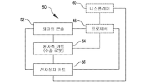
도 4는 로봇 수술 시스템(50)(도 1의 MIRS 시스템(10)과 같은)을 개략적으로 도시하고 있다. 전술한 바와 같이, 외과의 콘솔(52)(도 1의 외과의 콘솔(16)과 같은)은 외과의에 의해 최소 침습 수술 절차 중에 환자측 카트(수술 로봇)(54)(도 1의 환자측 카트(22)와 같은)를 제어하도록 사용될 수 있다. 환자측 카트(54)는 수술 부위의 영상을 촬영하고 촬영된 영상을 전자장치 카트(56)(도 1의 전자장치 카트(24)와 같은)로 출력하기 위해 입체 내시경과 같은 촬영 장치를 사용할 수 있다. 전술한 바와 같이, 전자장치 카트(56)는 임의의 후속적인 화면표시 전에 다양한 방법으로 촬영된 영상을 처리할 수 있다. 예컨대, 전자장치 카트(56)는 결합된 영상을 외과의 콘솔(52)을 통해 외과의에게 화면표시하기 전에 촬영된 영상들을 가상 제어 인터페이스로 중첩시킬 수 있다. 환자측 카트(54)는 촬영된 영상들을 전자장치 카트(56) 외부에서 처리하도록 출력할 수 있다. 예컨대, 환자측 카트(54)는 촬영된 영상들을 처리하기 위해 사용될 수 있는 프로세서(58)로 촬영된 영상들을 출력할 수 있다. 영상들은 또한 촬영된 영상들을 공동적으로, 순차적으로 그리고/또는 공동과 순차의 조합으로 처리하도록 함께 결합될 수 있는 전자장치 카트(56)와 프로세서(58)의 조합에 의해 처리될 수도 있다. 하나 이상의 별개의 디스플레이(60)가 또한 수술 부위의 영상이나 임의의 다른 관련 영상과 같은 영상의 현지 및/또는 원격 디스플레이를 위해 프로세서(58) 및/또는 전자장치 카트(56)와 결합될 수도 있다.4 schematically depicts a robotic surgical system 50 (such as the
도 5는 환자측 카트(22)를 도시하고 있다. 도시된 환자측 카트(22)는 3개의 수술 툴(26) 및 수술 부위의 영상의 촬영을 위해 사용되는 입체 내시경과 같은 촬영 장치(28)의 조작을 제공한다. 조작은 다수의 로봇 조인트를 갖는 로봇 기구에 의해 제공된다. 촬영 장치(28) 및 수술 툴(26)은 절개부의 크기를 최소화하기 위해 기구학적 운동 원격 중심(kinematic remote center)이 절개부에 유지되도록 환자의 절개부를 통해 위치결정되어 조작될 수 있다. 수술 부위의 영상은 수술 툴(26)의 원위 단부가 촬영 장치(28)의 시계 내에 위치결정될 때는 수술 툴(26)의 원위 단부의 영상을 포함할 수 있다.5 shows the
도 6은 다수의 실시예에 따른 로봇 수술 툴(100)을 도시한다. 로봇 수술 툴(100)은 수술 툴(26)의 한 예이다. 수술 툴(100)은 엔드 이펙터(102), 기다란 기기 샤프트 어셈블리(104) 및 근위 어셈블리(106)를 포함한다. 엔드 이펙터(102)는 기기 샤프트 어셈블리(104)의 원위 단부에서 기기 샤프트 어셈블리(104)에 의해 지지된다. 근위 어셈블리(106)는 근위 섀시(108) 및 근위 섀시(108)에 의해 지지되는 작동부(110)를 포함한다. 작동부(110)는 기기 샤프트 어셈블리(104)의 내강(lumen)을 따라 병진운동하도록 장착되는 작동 로드 어셈블리를 관절운동시키는데 사용되는 작동 케이블을 관절운동시키도록 구성된다. 작동 로드 어셈블리는 엔드 이펙터(102)에 구동 가능하게 연결되어 엔드 이펙터(102)에 푸시/풀 작동력(push/pull actuation force)을 전달하는 작동 로드를 포함한다. 엔드 이펙터 엔드 이펙터(102)에 전달되는 푸시/풀 작동력은 엔드 이펙터(102)의 임의의 적합한 기구, 예를 들어 조직을 클램핑(clamping)하는 조 관절운동 기구(jaw articulation mechanism), 클램핑된 조직에 스테이플(staple)을 배치시키는 스테이플 배치 기구(staple deployment mechanism) 및/또는 엔드 이펙터(102)에 의해 클램핑되고 스테이플링(stapling)된 조직을 커팅하는 커팅 기구를 작동시키는 데 사용될 수 있다.6 illustrates a robotic
도 7a 및 도 7B는 수술 툴(100)을 도시하는 간략화된 개략도이다. 수술 툴(100)은 엔드 이펙터(102)에 푸시/풀 작동력을 전달하기 위한 케이블 구동식 기구(112)를 포함한다. 케이블 구동식 기구(112)는 작동 로드 어셈블리(114), 풀리 어셈블리(116), 작동 케이블(118) 및 격리 튜브(isolation tube)(140)를 포함한다. 작동 로드 어셈블리(114)는 셔틀(120) 및 셔틀(120)에 고정적으로 부착되는 작동 로드(122)를 포함한다. 기기 샤프트 어셈블리(104)는 기기 샤프트 어셈블리(104)의 근위 단부(126)로부터 기기 샤프트 어셈블리(104)의 원위 단부(128)까지 연장되는 내강(lumen)(124)을 갖는다. 기기 샤프트 어셈블리(104)는 기기 샤프트 축(130)을 따라 연장된다. 셔틀(120)은 내강(124) 내에 배치되고, 기기 샤프트 축(130)에 평행하게 내강(124)을 따라 병진운동하도록 기기 샤프트 어셈블리(104) 내에 장착된다. 풀리 어셈블리(116)는 풀리(132) 및 풀리(132)를 지지하는 풀리 지지부(134)를 포함하고, 기기 샤프트 어셈블리(104)와 결합된다. 작동 케이블(118)은 연결부(136)에서 셔틀(120)에 부착된다. 작동 케이블(118)의 제1 부분은 연결부(136)로부터 원위측으로 풀리(132)까지 연장되고, 풀리(132) 둘레에 권취되고, 풀리(132)로부터 근위측으로 셔틀(120)의 근위 부분을 관통하는 가이드 구멍(138)까지 연장되고, 가이드 구멍(138)으로부터 근위측으로 격리 튜브(140)까지 연장되고, 격리 튜브(140)를 통해 연장되고, 격리 튜브(140)로부터 근위측으로 작동부(110)의 캡스턴(142)까지 연장되고, 캡스턴(142) 둘레에 제1 방향으로 권취된다. 작동 케이블(118)의 제2 부분은 연결부(136)로부터 근위측으로 격리 튜브(140)까지 연장되고, 격리 튜브(140)를 통해 연장되고, 격리 튜브(140)로부터 근위측으로 캡스턴(142)까지 연장되고, 캡스턴(142) 둘레에 제1 방향과 반대인 제2 방향으로 권취된다.7A and 7B are simplified schematic diagrams illustrating a
캡스턴(142)의 제어된 회전이 내강(124)을 따른 셔틀(120)의 병진운동을 제어하는 데 사용된다. 도시된 실시예에서, 캡스턴(142)의 반시계 방향 회전이 작동 케이블(118)의 제1 부분을 캡스턴(142)을 향해 당기고(또한 작동 케이블(118)의 제2 부분의 원위측 전진을 제공하고), 이에 의해 셔틀(120)을 원위측으로 엔드 이펙터(102)를 향해 당긴다. 셔틀(120)을 원위측으로 당김으로써 작동 로드(122)를 엔드 이펙터(102)를 향해 민다. 예를 들어, 캡스턴(142)은 셔틀(120)을 도 7a에 도시된 근위 위치로부터 도 7b에 도시된 원위 위치로 전진시키도록 회전될 수 있고, 이에 의해 작동 로드(122)를 작동 행정(actuation stroke)을 통해 원위측으로 전진시킨다. 유사한 방식으로, 캡스턴(142)은 셔틀(120)을 도 7b에 도시된 원위 위치로부터 도 7a에 도시된 근위 위치로 퇴축(retraction)시키도록 회전될 수 있고, 이에 의해 작동 로드(122)를 작동 행정을 통해 근위측으로 퇴축시킨다. 도 6에 도시된 원위 위치로부터 셔틀(120)을 퇴축시키도록 회전될 수 있다. 도시된 실시예에서, 셔틀(120)은 도 7a에 도시된 근위 위치로부터 도 7b에 도시된 원위 위치에 이르는 셔틀(120)의 모든 위치에 대해 풀리 어셈블리(116)를 수용하도록 구성된 중앙 슬롯을 갖는다.Controlled rotation of the
작동 로드(122)의 관절운동은 엔드 이펙터(102)의 임의의 적합한 기구를 작동시키기 위한 상당한 작동력을 엔드 이펙터(102)에 전달하는 데 사용될 수 있다. 예를 들어, 도 7a에 도시된 근위 위치로부터 도 7b에 도시된 원위 위치로의 및/또는 도 7b에 도시된 원위 위치로부터 도 7a의 근위 위치로의 작동 로드(122)의 관절운동은 조(jaw)와 엔드 이펙터(102)에 장착된 교체 가능한 스테이플러 카트리지(stapler cartridge) 사이에 조직을 클램핑하기 위해 엔드 이펙터의 조를 관절운동시키고, 스테이플러 카트리지로부터 스테이플러 카트리지와 조 사이에 클램핑된 조직 내로 스테이플을 배치시키기 위해 스테이플러 카트리지를 관절운동시키고 그리고/또는 스테이플러 카트리지와 조 사이에 클램핑되고 스테이플러 카트리지로부터 클램핑된 조직 내로 배치된 스테이플을 통해 스테이플링된 조직을 커팅하기 위해 커팅 요소를 관절운동시키는 데 사용될 수 있다.Articulation of the
다수의 실시예에서, 기기 샤프트 어셈블리(104)는 근위 섀시(108)에 대한 기기 샤프트 축(130) 둘레의 기기 샤프트 어셈블리(104)의 제어된 회전을 위해 근위 어셈블리(106)에 장착된다. 다수의 실시예에서, 셔틀(120)은 기기 샤프트 어셈블리(104)와 함께 회전하도록 내강(124) 내에 장착된다. 기기 샤프트 어셈블리(104)의 회전과 동반한 셔틀(120)의 회전의 결과로서, 작동 케이블(118)의 제2 부분의 일부분(연결부(136)로부터 캡스턴(142)까지 근위측으로 연장되는)과 가이드 구멍(138)으로부터 캡스턴(142)까지 근위측으로 연장되는 작동 케이블(118)의 제1 부분의 일부분이 근위 섀시(106)에 대한 기기 샤프트 어셈블리(104)의 회전량에 따라 상호 얽혀질 것이다. 다수의 실시예에서, 격리 튜브(140)는 작동 케이블(118)의 상호 얽힘 부분들의 적어도 일부분의 위치를 둘러싸고 그리고/또는 구속하도록 구성된다. 격리 튜브(140)는 격리 튜브(140)를 에워싸는 내강(124) 내에 배치되는 엔드 이펙터를 위한 하나 이상의 다른 부재를 작동 케이블(118)의 상호 얽힘 부분들로부터 격리시키는 데 사용되어, 작동 케이블(118)의 상호 얽힘이 주변의 하나 이상의 다른 작동 부재와 간섭하는 것을 방지할 수 있다.In some embodiments, the
도 8 내지 도 12는 도 7a 및 도 7b의 수술 툴(100)의 하나의 실시예를 도시한다. 도 8은 엔드 이펙터(102), 기기 샤프트 어셈블리(104)의 부분 모습, 근위 어셈블리(106), 풀리 어셈블리(116), 셔틀(120), 작동 로드(122) 및 격리 튜브(140)의 실시예를 도시한다. 도 9는 도 8의 수술 툴(100)의 실시예의 평면도로서, 기기 샤프트 어셈블리(104), 풀리 어셈블리(116), 셔틀(120), 작동 로드(122) 및 격리 튜브(140)의 부분 모습을 도시한다.8-12 show one embodiment of the
도 10은 도 8의 수술 툴(100)의 실시예의 확대도로서, 기기 샤프트 어셈블리(104)의 제1 구성요소(104(1)), 풀리 어셈블리(116), 셔틀(120), 작동 로드(122), 작동 케이블(118) 및 격리 튜브(140)를 도시한다. 짝을 이루는 기기 샤프트 어셈블리의 제2 구성요소(104(2))는 도 10에 도시되어 있지 않다. 예시된 실시예에서, 기기 샤프트 어셈블리(104)는 기기 샤프트 어셈블리(104)의 내강(124) 내의 작동 로드 어셈블리(114)(셔틀(120) 및 작동 로드(122)를 포함하는), 풀리 어셈블리(116), 격리 튜브(140) 및 작동 케이블(118)의 설치를 가능하게 해주기 위해 기기 샤프트 어셈블리(104)의 도시된 제1 구성요소(104(1)) 및 제2 구성요소(도 10에 도시되지 않음)를 포함한다. 도시된 실시예에서, 셔틀(120)은 제1 방향으로 돌출하는 제1 가이드 피처(144) 및 제1 방향과 상이한 제2 방향으로 돌출하는 제2 가이드 피처(146)를 포함한다. 도시된 실시예에서, 제2 방향은 제1 방향과 반대 방향이다. 기기 샤프트 어셈블리(104)의 제1 구성요소(104(1)) 및 짝을 이루는 제2 구성요소는 제1 가이드 피처(144)를 수용하도록 치수결정된 제1 슬롯(148) 및 제2 가이드 피처(146)를 수용하도록 치수결정된 제2 슬롯(150)을 형성하여, 기기 샤프트 어셈블리(104)에 대해 셔틀(120)의 이동의 전체 범위에 걸쳐 기기 샤프트 축(130)을 따라 병진운동하도록 셔틀(120)을 구속한다. 기기 샤프트 어셈블리(104)의 제1 구성요소(104(1)) 및 짝을 이루는 제2 구성요소는 또한 기기 샤프트 어셈블리(104)의 내강(124) 내의 풀리 어셈블리(116)의 설치를 가능하게 해주도록 구성된다. 예를 들어, 기기 샤프트 어셈블리(104)의 제1 구성요소(104(1)) 및 짝을 이루는 제2 구성요소는 풀리 지지부(134)의 계면 접촉부를 수용하여 계면 접촉하도록 구성되는 오목부를 포함하고, 이에 의해 풀리 지지부(134)를 기기 샤프트 어셈블리(104)의 내강(124) 내에 포착 및 구속할 수 있다. 유사한 방식으로, 기기 샤프트 어셈블리(104)의 제1 구성요소(104(1)) 및 짝을 이루는 제2 구성요소는 또한 기기 샤프트 어셈블리(104)의 내강(124) 내의 격리 튜브(140)의 설치를 가능하게 해주도록 구성된다. 예를 들어, 기기 샤프트 어셈블리(104)의 제1 구성요소(104(1)) 및 짝을 이루는 제2 구성요소는 격리 튜브(140)의 계면 접촉부를 수용하여 계면 접촉하도록 구성되는 오목부를 포함하고, 이에 의해 격리 튜브(140)를 기기 샤프트 어셈블리(104)의 내강(124) 내에 포착 및 구속할 수 있다.10 is an enlarged view of an embodiment of the
도 11 및 도 12는 수술 툴(100)의 근위 어셈블리(106)의 도면이다. 작동 케이블(118)은 캡스턴(142) 둘레에 권취된다. 캡스턴(142)은 기기 샤프트 축(130)에 수직인 캡스턴 축(152)을 중심으로 회전하도록 장착된다. 작동 입력부(154)를 통한 캡스턴(142)의 제어된 회전이 작동 로드(122)를 통한 엔드 이펙터(102)로의 작동력의 전달을 제어하도록 작동 케이블(118)의 제1 및 제2 부분의 전진(extension) 및 퇴축(retraction)을 제어한다. 도시된 실시예에서, 캡스턴(142)은 작동 케이블(118)로부터 장력을 조정하고 그리고/또는 느슨함을 제거하도록 작동 가능한 조정 피처(adjustment feature)를 포함한다.11 and 12 are views of the
도 13a 및 도 13b는 수술 툴(200)을 도시한 간략화된 개략도이다. 수술 툴(200)는 수술 툴(100)과 유사하지만, 케이블 구동식 기구(112)를 포함하는 대신에 엔드 이펙터(102)에 푸시/풀 작동력을 전달하기 위한 밴드 구동식 기구(212)를 포함한다. 밴드 구동식 기구(212)는 작동 로드 어셈블리(214), 구동 밴드 단부 지지부(216), 구동 밴드(218) 및 격리 튜브(240)를 포함한다. 작동 로드 어셈블리(214)는 셔틀(220) 및 셔틀(220)에 고정적으로 부착되는 작동 로드(222)를 포함한다. 기기 샤프트(204)는 기기 샤프트(204)의 근위 단부(226)로부터 기기 샤프트(204)의 원위 단부(228)까지 연장되는 내강(224)을 갖는다. 기기 샤프트(204)는 기기 샤프트 축(230)을 따라 연장된다. 셔틀(220)은 내강(224) 내에 배치되고, 기기 샤프트 축(230)을 따라 내강(224)을 따라 병진운동하도록 기기 샤프트(204)와 연결된다. 구동 밴드 단부 지지부(216)는 제1 베어링(232a) 및 제2 베어링(232b)을 지지하는 구동 밴드 단부 지지부 프레임(234)을 포함한다. 구동 밴드 단부 지지부 프레임(234)은 내강(224) 내에 배치되어 기기 샤프트(204)에 장착된다. 구동 밴드(218)는 연결부(236)에서 셔틀(220)에 부착된다. 구동 밴드(218)의 제1 부분은 연결부(236)로부터 원위측으로 제1 및 제2 베어링(232a, 232b)까지 연결되고, 제1 및 제2 베어링(232a, 232b) 둘레에 권취되고, 제1 및 제2 베어링(232a, 232b)으로부터 근위측으로 연결부(236) 반대편 셔틀(220) 측에서 셔틀(220)을 관통하는 가이드 구멍까지 연장되고, 가이드 구멍을 통해 연장되고, 가이드 구멍으로부터 근위측으로 격리 튜브(240)까지 연장되고, 격리 튜브(240)를 통해 연장되고, 격리 튜브(240)로부터 근위측으로 작동부(210)의 캡스턴(242)까지 연장되고, 캡스턴(242) 둘레에 제1 방향으로 권취된다. 작동 케이블(218)의 제2 부분은 연결부(236)로부근위측으로 격리 튜브(240)까지 연장되고, 격리 튜브(240)를 통해 연장되고, 격리 튜브(240)로부터 근위측으로 캡스턴(242)까지 근위측으로 연장되고, 캡스턴(242) 둘레에 제1 방향과 반대인 제2 방향으로 권취된다.13A and 13B are simplified schematic diagrams illustrating a
캡스턴(242)의 제어된 회전이 내강(224)을 따른 셔틀(220)의 병진운동을 제어하는 데 사용된다. 도시된 실시예에서, 캡스턴(242)의 제1 방향의 회전이 구동 밴드(218)의 제1 부분을 캡스턴(242)을 향해 당기고(또한 구동 밴드(218)의 제2 부분의 원위측 전진을 제공하고), 이에 의해 셔틀(220)을 원위측으로 엔드 이펙터(102)를 향해 당긴다. 셔틀(220)을 원위측으로 당김으로써 작동 로드(222)를 엔드 이펙터(102)를 향해 민다. 예를 들어, 캡스턴(242)은 셔틀(220)을 도 13a에 도시된 근위 위치로부터 도 13b에 도시된 원위 위치로 전진시키도록 회전될 수 있고, 이에 의해 작동 로드(222)를 작동 행정을 통해 원위측으로 전진시킨다. 유사한 방식으로, 캡스턴(242)은 셔틀(220)을 도 13b에 도시된 원위 위치로부터 도 13a에 도시된 근위 위치로 퇴축시키도록 회전될 수 있고, 이에 의해 작동 로드(222)를 근위측으로 퇴축시킨다.The controlled rotation of the
작동 로드(222)의 관절운동은 엔드 이펙터(102)의 임의의 적합한 기구를 작동시키기 위한 상당한 작동력을 엔드 이펙터(102)에 전달하는데 사용될 수 있다. 예를 들어 도 13a에 도시된 근위 위치로부터 도 13b에 도시된 원위 위치로의 및/또는 도 13b에 도시된 원위 위치로부터 도 13a에 도시된 근위 위치로의 작동 로드(222)의 관절운동은 조와 엔드 이펙터(102)에 장착된 교체 가능한 스테이플러 카트리지 사이에 조직을 클램핑하기 위해 엔드 이펙터의 조를 관절운동시키고, 스테이플러 카트리지로부터 스테이플러 카트리지와 조 사이에 클램핑된 조직 내로 스테이플을 배치시키기 위해 스테이플러 카트리지를 관절운동시키고 그리고/또는 스테이플러 카트리지와 조 사이에 클램핑되고 스테이플러 카트리지로부터 클램핑된 조직 내로 배치된 스테이플을 통해 스테이플링된 조직을 커팅하기 위해 커팅 요소를 관절운동시키는 데 사용될 수 있다.Articulation of the
도시된 실시예에서, 기기 샤프트(204)는 근위 섀시(208)에 대한 기기 샤프트 축(230) 둘레의 기기 샤프트(204)의 제어된 회전을 위해 근위 어셈블리(206)에 장착된다. 다수의 실시예에서, 셔틀(220)은 기기 샤프트(204)와 함께 회전하도록 내강(224) 내에 장착된다. 기기 샤프트(204)의 회전과 동반한 셔틀(220)의 회전의 결과로서, 구동 밴드(218)의 제2 부분의 일부분(연결부(236)로부터 캡스턴(242)까지 근위측으로 연장되는)과 셔틀(220)의 가이드 구멍으로부터 캡스턴(242)까지 근위측으로 연장되는 구동 밴드(218)의 제1 부분의 일부분이 근위 섀시(208)에 대한 기기 샤프트(204)의 회전량에 따라 상호 얽혀질 것이다. 다수의 실시예에서, 격리 튜브(240)는 구동 밴드(218)의 상호 얽힘 부분들의 적어도 일부분의 위치를 둘러싸고 그리고/또는 구속하도록 구성된다. 격리 튜브(240)는 격리 튜브(240)를 에워싸는 내강(224) 내에 배치되는 엔드 이펙터(102)를 위한 하나 이상의 다른 작동 부재를 구동 밴드(218)의 상호 얽힘 부분들로부터 격리시키는 데 사용되어, 구동 밴드(218)의 상호 얽힘이 주변의 하나 이상의 다른 작동 부재와 간섭하는 것을 방지할 수 있다.In the illustrated embodiment, the
도 14 내지 도 17은 도 13a 및 도 13b의 수술 툴(200)의 하나의 실시예를 도시한다. 도 14는 엔드 이펙터(102), 기기 샤프트(204), 근위 어셈블리(206), 구동 밴드 단부 지지부(216), 셔틀(220), 작동 로드(222) 및 격리 튜브(240)의 실시예를 도시한다. 도 15는 셔틀(220), 구동 밴드(218), 작동 로드(222), 기기 샤프트(204)의 제1 구성요소(204(1))(기기 샤프트(204)의 제2 구성요소(204(2))는 도 15에 도시되지 않음) 및 구동 밴드(218)와 셔틀(220) 사이의 연결부(236)를 도시한 확대도이다. 예시된 실시예에서, 연결부(236)는 구동 밴드(218)의 각각의 구멍을 통해 연장되고, 셔틀(220) 내의 각각의 나사 구멍과 상대결합되는 2개의 돌출 헤드 볼트(237)를 포함하고, 이에 의해 구동 밴드(218)의 국소 부분을 셔틀(220)에 고정시킨다.14-17 show one embodiment of the
예시된 실시예에서, 기기 샤프트(204)는 기기 샤프트(204)의 내강(224) 내의 작동 로드 어셈블리(214)(셔틀(220) 작동 로드(222)를 포함하는), 구동 밴드 단부 지지부(216), 격리 튜브(240) 및 구동 밴드(218)의 설치를 가능하게 해주기 위해 기기 샤프트(204)의 도시된 제1 구성요소(204(1)) 및 제2 구성요소(204(2)(도 15에는 도시되지 않고 도 16에 도시됨)를 포함한다. 도시된 실시예에서, 셔틀(220)은 제1 방향으로 돌출하는 제1 가이드 피처(244) 및 제1 방향과 상이한 제2 방향으로 돌출하는 제2 가이드 피처(246)(도 15에서는 숨겨짐)를 포함한다. 도시된 실시예에서, 제2 방향은 제1 방향과 반대 방향이다. 기기 샤프트(204)의 제1 구성요소(204(1))는 제2 가이드 피처(246)를 수용하도록 치수결정된 제1 슬롯(248)을 가지고, 제2 구성요소(204)는 제1 가이드 피처(244)를 수용하도록 치수결정된 제2 슬롯(250)을 가져, 기기 샤프트(204)에 대해 셔틀(220)의 이동의 전체 범위에 걸쳐 기기 샤프트 축(230)을 따라 병진운동하도록 셔틀(220)을 구속한다. 기기 샤프트(204)의 제1 구성요소(204(1)) 및 짝을 이루는 제2 구성요소(204(2))는 또한 기기 샤프트(204)의 내강(224) 내의 구동 밴드 단부 지지부(216)의 설치를 가능하게 해주도록 구성된다. 예를 들어, 기기 샤프트(204)의 제1 구성요소(204(1)) 및 짝을 이루는 제2 구성요소(204(2))는 구동 밴드 단부 지지부 프레임(234)의 계면 접촉부를 수용하여 계면 접촉하도록 구성되는 오목무를 포함하고, 이에 의해 구동 밴드 단부 지지부(216)를 기기 샤프트(204)의 내강(224) 내에 포착 및 구속할 수 있다. 유사한 방식으로, 기기 샤프트(204)의 제1 구성요소(204(1)) 및 짝을 이루는 제2 구성요소(204(2))는 또한 기기 샤프트(204)의 내강(224) 내의 격리 튜브(240)의 설치를 가능하게 해주도록 구성된다. 예를 들어, 기기 샤프트(240)의 제1 구성요소(204(1)) 및 짝을 이루는 제2 구성요소(204(2))는 격리 튜브(240)의 계면 접촉부를 수용하여 계면 접촉하도록 구성되는 오목부를 포함하고, 이에 의해 격리 튜브(240)를 기기 샤프트(204)의 내강(224) 내에 포착 및 구속할 수 있다.In the illustrated embodiment, the
도 16은 구동 밴드(218)가 연장되는 가이드 슬롯을 형성하는 셔틀(220) 및 가이드 핀(238a, 238b)을 도시한 확대도이다. 구동 밴드(218)의 작동을 통한 셔틀(220)의 작동 시에, 구동 밴드(218)는 가이드 핀(238a, 238b)과 셔틀(220) 사이의 가이드 슬롯을 통해 슬라이딩한다. 도 16은 또한 기기 샤프트(204)의 제2 가이드 피처(246) 및 제2 구성요소(204(2))를 도시한다.Fig. 16 is an enlarged view showing the
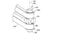
도 17은 구동 밴드 단부 지지부(216)를 도시한 확대도이다. 구동 밴드 단부 지지부(216)는 구동 밴드 단부 지지부 프레임(234)과, 기기 샤프트 축(230)과 수직하고 구동 밴드(218)의 양 면과 평행한 구동 밴드 단부 지지부 축(252)을 중심으로 회전하도록 구동 밴드 단부 지지부 프레임(234) 상에 장착되는 제1 및 제2 베어링(232a, 232b)를 포함한다. 구동 밴드 단부 지지부 프레임(234)은 작동 로드(222)를 수용하도록 치수결정된 구멍(254)을 가지며, 작동 로드(222)가 이 구멍(254)을 통해 연장된다. 구동 밴드 단부 지지부 프레임(234)은 기기 샤프트(204)의 내강(224) 내의 고정된 위치에서 구동 밴드 단부 지지부 프레임(234)을 지지하도록 기기 샤프트(204) 내의 상보적인 형상의 오목부와 상대결합하는 제1 및 제2 단부 저널(256, 258)을 포함한다.17 is an enlarged view showing the drive
다른 변형예도 본 발명의 기술 사상 내에 속한다. 예를 들어, 5개의 상이한 유형의 스테이플러 카트리지가 여기에 설명되지만, 설명된 5개의 스테이플러 카트리지 유형보다 적거나 많은 수를 포함하여 임의의 적절한 수의 스테이플러 카트리지 유형이 사용될 수 있다. 따라서, 본 발명은 다양한 수정 및 대안적인 구성이 가능하지만, 그 특정 예시의 실시예가 도면에 도시되어 상세히 기술되었다. 하지만, 본 발명을 개시된 특정 형태로 한정하려는 의도는 없으며, 그와 반대로 첨부된 청구범위에서 한정되는 것으로서, 본 발명의 기술 사상 및 범위 내에 속하는 모든 변형, 대안적인 구성 및 균등예를 커버하는 것으로 의도된다.Other modifications also fall within the spirit of the present invention. For example, while five different types of stapler cartridges are described herein, any suitable number of stapler cartridge types may be used, including fewer or more than the five stapler cartridge types described. Accordingly, while the present invention is susceptible to various modifications and alternative arrangements, specific illustrative embodiments thereof have been shown in detail and have been described in detail in the drawings. However, it is not intended to limit the present invention to the specific form disclosed, and, on the contrary, is intended to cover all modifications, alternative constructions and equivalents falling within the spirit and scope of the present invention, as defined by the appended claims. do.
본 발명의 설명하는 문맥에서(특히 이하의 청구범위의 문맥에서)에서의 "하나의", "그 하나의" 및 이와 유사한 표현은, 달리 지시되지 않았거나 문장에서 명백하게 부정되지 않았다면, 단일 형태와 복수 형태를 모두 포괄하는 것을 해석되어야 한다. "포함하다", "가지다", "구비하다", "보유하다"의 상당 표현은, 달리 지시되지 않았다면, 개방형의 표현(즉, 구비하되 그것에 한정되지 않는다는 것을 의미)으로 해석되어야 한다. "연결되다"의 상당 표현은, 달리 지적되지 않았다면, 일부 또는 전체가 수용되거나, 부착되거나, 서로 결합되는 것으로 해석되어야 한다. 여기에서의 수치값의 범위의 기술은, 달리 지시되지 않았다면, 단지 그 범위 내에 속하는 각각의 개별의 수치값을 개별적으로 기술하는 것을 대신하는 방법으로 작용하며, 각각의 개별의 수치값은 마치 개별적으로 언급된 것처럼 본 명세서에 포함된다. 여기에 설명되는 모든 방법은, 달리 지시되지 않았거나 문장에서 명백하게 부정되지 않았다면, 임의의 적합한 순서로 실행될 수 있다. 실시예의 사용 또는 여기에 사용된 예시의 표현(예컨대, "와 같은")는 단지 발명을 더 명확하게 설명하기 위한 것으로, 달리 청구되지 않는다면 발명의 범위를 제한하지 않는다. 명세서 내의 어떠한 표현도 본 발명의 실시예 필수적인 것으로 청구되지 않은 요소를 지시하는 것으로 해석되어서는 안된다.In the context of the description of the invention (especially in the context of the claims that follow), the expressions "a", "the one" and the like are used in singular form and unless otherwise indicated or clearly contradicted by the text. It should be construed to encompass all plural forms. Equivalent expressions of "include", "have", "have", "have" are to be construed as open-ended expressions (ie, meaning to include, but not limited to), unless otherwise indicated. The equivalent expression of “connected” is to be construed as being accommodated, attached to, or joined to one another, in part or in whole, unless otherwise indicated. The description of ranges of numerical values herein, unless otherwise indicated, merely serves as a substitute for individually recounting each individual numerical value falling within that range, and each individual numerical value is treated as if it were individually As mentioned, it is incorporated herein by reference. All methods described herein can be performed in any suitable order unless otherwise indicated or otherwise clearly contradicted by a sentence. The use of embodiments or illustrative language (eg, "such as") used herein is merely to better illuminate the invention and does not limit the scope of the invention unless otherwise claimed. No language in the specification should be construed as indicating an element that is not claimed as essential to the embodiment of the present invention.
본 발명자들에게 알려진 본 발명을 실시하기 위한 최적의 모드를 포함하여, 바람직한 실시예를 설명하였다. 그러한 바람직한 실시예의 변경은 이상의 설명으로부터 당업자에게 자명할 수 있다. 본 발명자들은 당업자가 그러한 변경을 적절히 채용할 것으로 기대하며, 본 발명자들은 본 발명이 여기에 특정적으로 설명된 것과 다른 방식으로 실시되는 것을 의도하고 있다. 따라서, 본 발명은 적용가능한 법에 의해 허용되는 것으로서 첨부의 청구범위에 기술된 청구대상의 모든 변경들 및 균등 사항들을 포함한다. 또한, 모든 가능한 변형에 있어 전술한 요소들의 임의의 조합도, 달리 지시되지 않았거나 문장에서 명백하게 부정되지 않았다면, 본 발명에 포함되는 것이다.A preferred embodiment has been described, including the best mode for carrying out the invention known to the inventors. Modifications of such preferred embodiments will be apparent to those skilled in the art from the above description. The inventors expect skilled artisans to employ such modifications as appropriate, and the inventors intend for the invention to be practiced otherwise than as specifically described herein. Accordingly, this invention includes all modifications and equivalents of the subject matter recited in the appended claims as permitted by applicable law. Further, in all possible variations any combination of the above elements is intended to be encompassed by the present invention, unless otherwise indicated or otherwise clearly contradicted by the text.
본원에 인용되는 간행물, 특허 출원 및 특허를 포함하는 모든 인용 문헌은 마치 각각의 문헌이 개별적으로 또한 특정적으로 참고 문헌으로 인용되도록 지시되고 그 전체가 여기에 기술된 것 같은 동일한 정도로 본원에 참조된다.All cited documents, including publications, patent applications and patents, cited herein are incorporated herein by reference to the same extent as if each document were individually and specifically indicated to be incorporated by reference and were set forth herein in their entirety. .
Claims (20)
근위 작동 어셈블리;
엔드 이펙터;
내강을 한정하는 기기 샤프트를 포함하는 기기 샤프트 어셈블리 및 내강 내로 연장되는 작동 로드를 포함하는 작동 로드 어셈블리로서, 기기 샤프트는 엔드 이펙터를 지지하고, 작동 로드는 엔드 이펙터와 구동 가능하게 연결되는, 기기 샤프트 어셈블리 및 작동 로드 어셈블리; 및
작동 로드를 근위 작동 어셈블리에 구동 가능하게 연결시키는 가요성 인장 부재로서, 근위 작동 어셈블리는 엔드 이펙터를 작동시키기 위해 엔드 이펙터를 향해 작동 로드를 이동시켜 가요성 인장 부재의 장력을 증가시키도록 작동 가능한, 가요성 인장 부재를 포함하는 것을 특징으로 하는 수술 툴.In the surgical tool,
proximal actuation assembly;
end effector;
An actuation rod assembly comprising an instrument shaft assembly defining a lumen and an actuation rod extending into the lumen, the instrument shaft supporting an end effector, the actuation rod drivably connected with the end effector; assembly and working rod assembly; and
A flexible tension member drivably coupling the actuation rod to the proximal actuation assembly, the proximal actuation assembly operable to move the actuation rod toward the end effector to increase tension of the flexible tension member; A surgical tool comprising a flexible tension member.
근위 작동 어셈블리는 작동 로드를 엔드 이펙터로부터 먼 쪽으로 이동시키기 위해 가요성 인장 부재의 장력을 증가시키도록 작동 가능한 것을 특징으로 하는 수술 툴.The method of claim 1,
wherein the proximal actuation assembly is operable to increase tension of the flexible tension member to move the actuation rod away from the end effector.
근위 작동 어셈블리는 기기 샤프트를 지지하는 근위 섀시에 대해 기기 샤프트를 회전시키도록 작동 가능하고,
작동 로드는 기기 샤프트와 함께 회전하도록 구속되고;
기기 샤프트 어셈블리는 가요성 인장 부재가 연장되어 통과하는 격리 튜브를 포함하고, 격리 튜브는 격리 튜브를 에워싸는 내강 영역으로부터 가요성 인장 부재를 격리시키는 것을 특징으로 하는 수술 툴.3. The method of claim 2,
the proximal actuation assembly is operable to rotate the instrument shaft relative to a proximal chassis supporting the instrument shaft;
the actuating rod is constrained to rotate with the instrument shaft;
wherein the instrument shaft assembly includes an isolation tube through which the flexible tension member extends, the isolation tube isolating the flexible tension member from the lumen region surrounding the isolation tube.
가요성 인장 부재는 구동 밴드를 포함하고;
구동 밴드는 작동 로드 어셈블리의 일부분이 연장되어 통과하는 슬롯을 포함하는 것을 특징으로 하는 수술 툴.The method of claim 1,
The flexible tension member includes a drive band;
wherein the drive band includes a slot through which a portion of the actuation rod assembly extends.
작동 로드 어셈블리의 일부분이 연장되어 통과하는 구멍을 가지는 지지부 프레임; 및
지지부 프레임에 장착되고 구동 밴드와 계면 접촉하는 베어링을 포함하는 것을 특징으로 하는 수술 툴.9. The apparatus of claim 8, wherein the instrument shaft assembly comprises:
a support frame having a hole through which a portion of the actuation rod assembly extends; and
A surgical tool comprising a bearing mounted to the support frame and in interfacial contact with the drive band.
내강을 한정하는 기기 샤프트를 통해 엔드 이펙터를 지지하는 단계;
내강 내에서 작동 로드 어셈블리를 지지하는 단계로서, 작동 로드 어셈블리는 엔드 이펙터과 구동 가능하게 연결되는 작동 로드를 포함하는, 지지 단계; 및
엔드 이펙터를 작동시키기 위해 엔드 이펙터를 향해 작동 로드를 이동시켜 작동 로드와 연결된 가요성 인장 부재의 장력을 증가시키도록 근위 작동 어셈블리를 작동시키는 단계를 포함하는 것을 특징으로 하는 방법.A method for actuating an end effector of a surgical tool, comprising:
supporting the end effector via an instrument shaft defining a lumen;
supporting an actuation rod assembly within the lumen, the actuation rod assembly comprising an actuation rod drivably coupled with an end effector; and
and actuating the proximal actuation assembly to move the actuation rod toward the end effector to actuate the end effector to increase tension in a flexible tension member associated with the actuation rod.
기기 샤프트를 지지하는 근위 섀시에 대해 기기 샤프트 축 둘레로 기기 샤프트를 회전시키도록 근위 작동 어셈블리를 작동시키는 단계;
기기 샤프트 축 둘레로 기기 샤프트와 함께 회전하도록 작동 로드를 구속하는 단계; 및
격리 튜브를 에워싸는 내강 영역으로부터 상호 얽힘 가능한 길이 부분을 격리시키기 위해 작동 로드와 근위 작동 어셈블리 사이에 배치되는 가요성 인장 부재의 상호 얽힘 가능한 길이 부분을 격리 튜브 내에 둘러싸 넣는 단계를 추가로 포함하는 것을 특징으로 하는 방법.13. The method of claim 12,
actuating the proximal actuation assembly to rotate the instrument shaft about an instrument shaft axis relative to a proximal chassis supporting the instrument shaft;
constraining the actuation rod to rotate with the instrument shaft about the instrument shaft axis; and
enclosing within the isolation tube the entangling length portion of the flexible tension member disposed between the actuation rod and the proximal actuation assembly to isolate the entangling length portion from the lumen region surrounding the isolation tube. how to do it with
작동 로드 어셈블리 및 가요성 인장 부재를 기기 샤프트의 제1 부분 내로 삽입하는 단계; 및
작동 로드 어셈블리 및 가요성 인장 부재의 일부분을 기기 샤프트의 내강 내에 둘러싸 넣기 위해 기기 샤프트의 제2 부분을 기기 샤프트의 제1 부분에 결합시키는 단계를 추가로 포함하는 것을 특징으로 하는 방법.12. The method of claim 11,
inserting the actuation rod assembly and the flexible tension member into the first portion of the instrument shaft; and
and coupling a second portion of the instrument shaft to the first portion of the instrument shaft to enclose a portion of the actuation rod assembly and flexible tension member within a lumen of the instrument shaft.
가요성 인장 부재와 계면 접촉하는 가이드 표면에 대한 이동의 범위에 걸쳐 작동 로드를 이동시키기 위해 근위 작동 어셈블리를 작동시키는 단계; 및
이동의 범위에 걸쳐 기기 샤프트에 대한 작동 로드의 이동을 가이드하기 위해 작동 로드의 돌출하는 가이드 피처를 기기 샤프트에 계면 접촉시키는 단계를 추가로 포함하는 것을 특징으로 하는 방법.17. The method of claim 16,
actuating the proximal actuation assembly to move the actuation rod over a range of motion relative to a guide surface in interfacial contact with the flexible tension member; and
and interfacially contacting the protruding guide feature of the actuating rod to the instrument shaft to guide movement of the actuating rod relative to the instrument shaft over a range of motion.
기기 샤프트를 통해 지지부 프레임을 지지하는 단계;
지지부 프레임을 통과하는 구멍 내에 작동 로드의 일부분을 수용하는 단계;
가이드 표면 축 둘레로 회전하기 위해 지지부 프레임에 장착되는 제1 베어링을 지지하는 단계로서, 구동 밴드는 제1 베어링과 계면 접촉하는, 지지 단계; 및
가이드 표면 축 둘레로 회전하기 위해 지지부 프레임에 장착되는 제2 베어링을 지지하는 단계로서, 구동 밴드는 제2 베어링과 계면 접촉하는, 지지 단계를 추가로 포함하는 것을 특징으로 하는 방법.19. The method of claim 18,
supporting the support frame via the instrument shaft;
receiving a portion of the actuation rod in an aperture passing through the support frame;
supporting a first bearing mounted to a support frame for rotation about a guide surface axis, wherein the drive band is in interfacial contact with the first bearing; and
supporting a second bearing mounted to the support frame for rotation about the guide surface axis, wherein the drive band is in interfacial contact with the second bearing.
Applications Claiming Priority (4)
| Application Number | Priority Date | Filing Date | Title |
|---|---|---|---|
| US201662385642P | 2016-09-09 | 2016-09-09 | |
| US62/385,642 | 2016-09-09 | ||
| PCT/US2017/050760 WO2018049217A1 (en) | 2016-09-09 | 2017-09-08 | Push-pull surgical instrument end effector actuation using flexible tension member |
| KR1020197007097A KR102456414B1 (en) | 2016-09-09 | 2017-09-08 | Push-Pull Surgical Instrument End Effector Activation Using a Flexible Tensile Member |
Related Parent Applications (1)
| Application Number | Title | Priority Date | Filing Date |
|---|---|---|---|
| KR1020197007097A Division KR102456414B1 (en) | 2016-09-09 | 2017-09-08 | Push-Pull Surgical Instrument End Effector Activation Using a Flexible Tensile Member |
Publications (1)
| Publication Number | Publication Date |
|---|---|
| KR20220143778A true KR20220143778A (en) | 2022-10-25 |
Family
ID=61562125
Family Applications (2)
| Application Number | Title | Priority Date | Filing Date |
|---|---|---|---|
| KR1020197007097A KR102456414B1 (en) | 2016-09-09 | 2017-09-08 | Push-Pull Surgical Instrument End Effector Activation Using a Flexible Tensile Member |
| KR1020227035598A KR20220143778A (en) | 2016-09-09 | 2017-09-08 | Push-pull surgical instrument end effector actuation using flexible tension member |
Family Applications Before (1)
| Application Number | Title | Priority Date | Filing Date |
|---|---|---|---|
| KR1020197007097A KR102456414B1 (en) | 2016-09-09 | 2017-09-08 | Push-Pull Surgical Instrument End Effector Activation Using a Flexible Tensile Member |
Country Status (6)
| Country | Link |
|---|---|
| US (2) | US11020138B2 (en) |
| EP (3) | EP3949892B1 (en) |
| JP (3) | JP7044760B2 (en) |
| KR (2) | KR102456414B1 (en) |
| CN (2) | CN113598844A (en) |
| WO (1) | WO2018049217A1 (en) |
Families Citing this family (50)
| Publication number | Priority date | Publication date | Assignee | Title |
|---|---|---|---|---|
| US10076348B2 (en) | 2013-08-15 | 2018-09-18 | Intuitive Surgical Operations, Inc. | Rotary input for lever actuation |
| CN110074844B (en) | 2013-12-11 | 2023-02-17 | 柯惠Lp公司 | Wrist assembly and jaw assembly for robotic surgical system |
| EP3258874B1 (en) | 2015-02-19 | 2024-01-17 | Covidien LP | Input device for robotic surgical system |
| JP2018507727A (en) | 2015-03-10 | 2018-03-22 | コヴィディエン リミテッド パートナーシップ | Measuring the normality of connector members in robotic surgical systems. |
| CN107820412B (en) | 2015-06-23 | 2021-01-15 | 柯惠Lp公司 | Robotic surgical assembly |
| WO2017053363A1 (en) | 2015-09-25 | 2017-03-30 | Covidien Lp | Robotic surgical assemblies and instrument drive connectors thereof |
| WO2017087439A1 (en) | 2015-11-19 | 2017-05-26 | Covidien Lp | Optical force sensor for robotic surgical system |
| US11576562B2 (en) | 2016-04-07 | 2023-02-14 | Titan Medical Inc. | Camera positioning method and apparatus for capturing images during a medical procedure |
| EP3463162A4 (en) | 2016-06-03 | 2020-06-24 | Covidien LP | Systems, methods, and computer-readable program products for controlling a robotically delivered manipulator |
| WO2017210499A1 (en) | 2016-06-03 | 2017-12-07 | Covidien Lp | Control arm for robotic surgical systems |
| KR102543919B1 (en) | 2016-07-14 | 2023-06-16 | 인튜어티브 서지컬 오퍼레이션즈 인코포레이티드 | Multi-cable medical instrument |
| US20190231451A1 (en) | 2016-07-14 | 2019-08-01 | Intuitive Surgical Operations, Inc. | Geared roll drive for medical instrument |
| US11007024B2 (en) | 2016-07-14 | 2021-05-18 | Intuitive Surgical Operations, Inc. | Geared grip actuation for medical instruments |
| WO2018094191A1 (en) | 2016-11-21 | 2018-05-24 | Intuitive Surgical Operations, Inc. | Cable length conserving medical instrument |
| US11690691B2 (en) | 2017-02-15 | 2023-07-04 | Covidien Lp | System and apparatus for crush prevention for medical robot applications |
| US10357321B2 (en) | 2017-02-24 | 2019-07-23 | Intuitive Surgical Operations, Inc. | Splayed cable guide for a medical instrument |
| WO2018217429A1 (en) | 2017-05-24 | 2018-11-29 | Covidien Lp | Presence detection for electrosurgical tools in a robotic system |
| EP3629980A4 (en) | 2017-05-25 | 2021-03-10 | Covidien LP | Robotic surgical system with automated guidance |
| JP7349992B2 (en) | 2017-09-05 | 2023-09-25 | コヴィディエン リミテッド パートナーシップ | Collision handling algorithms for robotic surgical systems |
| AU2019205201B2 (en) | 2018-01-04 | 2020-11-05 | Covidien Lp | Systems and assemblies for mounting a surgical accessory to robotic surgical systems, and providing access therethrough |
| US11497567B2 (en) | 2018-02-08 | 2022-11-15 | Intuitive Surgical Operations, Inc. | Jointed control platform |
| US11118661B2 (en) | 2018-02-12 | 2021-09-14 | Intuitive Surgical Operations, Inc. | Instrument transmission converting roll to linear actuation |
| EP3817683A4 (en) | 2018-07-03 | 2022-04-20 | Covidien LP | Systems, methods, and computer-readable media for detecting image degradation during surgical procedures |
| US20210401523A1 (en) * | 2018-11-15 | 2021-12-30 | Intuitive Surgical Operations, Inc. | Surgical instrument with sensor aligned cable guide |
| WO2020102778A1 (en) | 2018-11-15 | 2020-05-22 | Intuitive Surgical Operations, Inc. | Strain sensor with contoured deflection surface |
| EP3897405A4 (en) | 2018-12-21 | 2022-09-14 | Intuitive Surgical Operations, Inc. | Actuation mechanisms for surgical instruments |
| US11723661B2 (en) | 2018-12-21 | 2023-08-15 | Intuitive Surgical Operations, Inc. | Surgical instruments with switches for deactivating and/or identifying stapler cartridges |
| JP7241178B2 (en) | 2018-12-21 | 2023-03-16 | インテュイティブ サージカル オペレーションズ, インコーポレイテッド | Surgical instrument with reinforced staple cartridge |
| US11576733B2 (en) | 2019-02-06 | 2023-02-14 | Covidien Lp | Robotic surgical assemblies including electrosurgical instruments having articulatable wrist assemblies |
| US11944302B2 (en) | 2019-04-15 | 2024-04-02 | Intuitive Surgical Operations, Inc. | Staple cartridge for a surgical instrument |
| EP3975875A4 (en) | 2019-05-31 | 2023-02-01 | Intuitive Surgical Operations, Inc. | Staple cartridge for a surgical instrument |
| CN113017835B (en) * | 2019-12-25 | 2022-11-11 | 杭州术创机器人有限公司 | Cable tensioning device for surgical tool assembly |
| US11771422B2 (en) | 2020-05-12 | 2023-10-03 | Covidien Lp | Active roller assembly for use in articulating stapler |
| USD963851S1 (en) | 2020-07-10 | 2022-09-13 | Covidien Lp | Port apparatus |
| CN112754545A (en) * | 2020-12-19 | 2021-05-07 | 深圳市精锋医疗科技有限公司 | Tensioning mechanism, surgical instrument, slave operation device and surgical robot |
| CN116669636A (en) | 2021-01-08 | 2023-08-29 | 直观外科手术操作公司 | Surgical stapling instrument |
| US11948226B2 (en) | 2021-05-28 | 2024-04-02 | Covidien Lp | Systems and methods for clinical workspace simulation |
| CN113208736B (en) * | 2021-05-31 | 2023-02-10 | 上海微创医疗机器人(集团)股份有限公司 | Instrument driving device, instrument tail end assembly, surgical instrument and surgical robot |
| US20230045893A1 (en) | 2021-08-16 | 2023-02-16 | Cilag Gmbh International | Multi-position restraining member for sled movement |
| EP4199837A1 (en) | 2021-08-16 | 2023-06-28 | Cilag GmbH International | Proximally located firing lockout mechanism for surgical stapler |
| US20230045998A1 (en) * | 2021-08-16 | 2023-02-16 | Cilag Gmbh International | Firing bailout system for powered surgical stapler |
| US20230050707A1 (en) | 2021-08-16 | 2023-02-16 | Cilag Gmbh International | Firing system features for surgical stapler |
| US11944297B2 (en) | 2021-08-16 | 2024-04-02 | Cilag Gmbh International | Variable response motor control algorithm for powered surgical stapler |
| US20230051938A1 (en) | 2021-08-16 | 2023-02-16 | Cilag Gmbh International | Adjustable power transmission mechanism for powered surgical stapler |
| US11779332B2 (en) | 2021-08-16 | 2023-10-10 | Cilag Gmbh International | Powered surgical stapler having independently operable closure and firing systems |
| US20230051222A1 (en) | 2021-08-16 | 2023-02-16 | Cilag Gmbh International | Cartridge-based firing lockout mechanism for surgical stapler |
| US20230049736A1 (en) | 2021-08-16 | 2023-02-16 | Cilag Gmbh International | Firing member tracking feature for surgical stapler |
| US20230051271A1 (en) | 2021-08-16 | 2023-02-16 | Cilag Gmbh International | Multi-threshold motor control algorithm for powered surgical stapler |
| US20230050358A1 (en) | 2021-08-16 | 2023-02-16 | Cilag Gmbh International | Multiple-sensor firing lockout mechanism for powered surgical stapler |
| US20230052307A1 (en) | 2021-08-16 | 2023-02-16 | Cilag Gmbh International | Deflectable firing member for surgical stapler |
Citations (1)
| Publication number | Priority date | Publication date | Assignee | Title |
|---|---|---|---|---|
| JP2010249818A (en) | 2009-04-20 | 2010-11-04 | Javad Gnss Inc | Laser beam image contrast enhancement |
Family Cites Families (18)
| Publication number | Priority date | Publication date | Assignee | Title |
|---|---|---|---|---|
| JP2002543865A (en) | 1999-05-10 | 2002-12-24 | ブロック ロジャース サージカル インコーポレイティド | Surgical instruments |
| JP3745234B2 (en) * | 2000-06-13 | 2006-02-15 | オリンパス株式会社 | Endoscopic treatment tool |
| US20030135204A1 (en) * | 2001-02-15 | 2003-07-17 | Endo Via Medical, Inc. | Robotically controlled medical instrument with a flexible section |
| US6994708B2 (en) * | 2001-04-19 | 2006-02-07 | Intuitive Surgical | Robotic tool with monopolar electro-surgical scissors |
| US7121781B2 (en) | 2003-06-11 | 2006-10-17 | Intuitive Surgical | Surgical instrument with a universal wrist |
| US7126303B2 (en) | 2003-07-08 | 2006-10-24 | Board Of Regents Of The University Of Nebraska | Robot for surgical applications |
| US7951165B2 (en) * | 2003-08-18 | 2011-05-31 | Boston Scientific Scimed, Inc. | Endoscopic medical instrument and related methods of use |
| WO2008045333A2 (en) | 2006-10-05 | 2008-04-17 | Tyco Healthcare Group Lp | Flexible endoscopic stitching devices |
| US8870867B2 (en) * | 2008-02-06 | 2014-10-28 | Aesculap Ag | Articulable electrosurgical instrument with a stabilizable articulation actuator |
| JP5400444B2 (en) * | 2009-03-27 | 2014-01-29 | テルモ株式会社 | Method for manufacturing medical device and medical device |
| JP5734631B2 (en) | 2010-12-02 | 2015-06-17 | オリンパス株式会社 | Surgery support system |
| JP5856817B2 (en) | 2011-11-16 | 2016-02-10 | オリンパス株式会社 | Medical treatment tool and manipulator having the same |
| US9125681B2 (en) * | 2012-09-26 | 2015-09-08 | Ethicon Endo-Surgery, Inc. | Detachable end effector and loader |
| JP6033456B2 (en) * | 2013-02-27 | 2016-11-30 | オリンパス株式会社 | manipulator |
| US9839481B2 (en) * | 2013-03-07 | 2017-12-12 | Intuitive Surgical Operations, Inc. | Hybrid manual and robotic interventional instruments and methods of use |
| US9889568B2 (en) | 2013-03-14 | 2018-02-13 | Sri International | Compact robotic wrist |
| JP6153484B2 (en) | 2014-02-24 | 2017-06-28 | オリンパス株式会社 | Wire drive device and manipulator |
| JP6408024B2 (en) * | 2014-10-30 | 2018-10-17 | オリンパス株式会社 | Medical treatment tool |
-
2017
- 2017-09-08 KR KR1020197007097A patent/KR102456414B1/en active Application Filing
- 2017-09-08 EP EP21183988.1A patent/EP3949892B1/en active Active
- 2017-09-08 US US16/331,734 patent/US11020138B2/en active Active
- 2017-09-08 CN CN202111060942.5A patent/CN113598844A/en active Pending
- 2017-09-08 JP JP2019510811A patent/JP7044760B2/en active Active
- 2017-09-08 KR KR1020227035598A patent/KR20220143778A/en active IP Right Grant
- 2017-09-08 EP EP17849648.5A patent/EP3509523B1/en active Active
- 2017-09-08 EP EP23162476.8A patent/EP4218653A1/en active Pending
- 2017-09-08 WO PCT/US2017/050760 patent/WO2018049217A1/en unknown
- 2017-09-08 CN CN201780054562.6A patent/CN109688959B/en active Active
-
2021
- 2021-05-05 US US17/308,368 patent/US20210267617A1/en active Pending
-
2022
- 2022-03-17 JP JP2022042360A patent/JP7335382B2/en active Active
-
2023
- 2023-08-17 JP JP2023133177A patent/JP2023144088A/en active Pending
Patent Citations (1)
| Publication number | Priority date | Publication date | Assignee | Title |
|---|---|---|---|---|
| JP2010249818A (en) | 2009-04-20 | 2010-11-04 | Javad Gnss Inc | Laser beam image contrast enhancement |
Also Published As
| Publication number | Publication date |
|---|---|
| KR20190040496A (en) | 2019-04-18 |
| US11020138B2 (en) | 2021-06-01 |
| CN109688959B (en) | 2021-10-01 |
| CN113598844A (en) | 2021-11-05 |
| KR102456414B1 (en) | 2022-10-19 |
| EP3509523A4 (en) | 2020-05-13 |
| US20190201150A1 (en) | 2019-07-04 |
| CN109688959A (en) | 2019-04-26 |
| WO2018049217A1 (en) | 2018-03-15 |
| JP2023144088A (en) | 2023-10-06 |
| JP7335382B2 (en) | 2023-08-29 |
| US20210267617A1 (en) | 2021-09-02 |
| JP2022069664A (en) | 2022-05-11 |
| EP3949892B1 (en) | 2023-04-19 |
| EP3509523A1 (en) | 2019-07-17 |
| EP3509523B1 (en) | 2021-07-21 |
| JP2019526333A (en) | 2019-09-19 |
| EP3949892A1 (en) | 2022-02-09 |
| JP7044760B2 (en) | 2022-03-30 |
| EP4218653A1 (en) | 2023-08-02 |
Similar Documents
| Publication | Publication Date | Title |
|---|---|---|
| KR102456414B1 (en) | Push-Pull Surgical Instrument End Effector Activation Using a Flexible Tensile Member | |
| US20220151717A1 (en) | Robotic surgical stapler assembly configured to use stapler reload | |
| JP6778246B2 (en) | Surgical instrument with a knife blade that can be stowed away | |
| KR102597849B1 (en) | Reconfigurable end effector structure | |
| KR102377893B1 (en) | Method for engaging surgical instrument with teleoperated actuator | |
| KR102009224B1 (en) | End effector with redundant closing mechanisms | |
| CN113194847A (en) | Actuation mechanism for a surgical instrument | |
| EP2713910B1 (en) | Grip force control in a robotic surgical instrument | |
| US20210022819A1 (en) | Articulable medical devices having flexible wire routing | |
| JP2022515163A (en) | Surgical instrument with reinforced staple cartridge | |
| KR101750628B1 (en) | An apparatus for surgery comprising a surgical arm attached to the endoscope and a surgery system comprising thereof |
Legal Events
| Date | Code | Title | Description |
|---|---|---|---|
| A107 | Divisional application of patent | ||
| A201 | Request for examination | ||
| E902 | Notification of reason for refusal | ||
| E90F | Notification of reason for final refusal | ||
| E701 | Decision to grant or registration of patent right |