EP3509523B1 - Push-pull surgical instrument end effector actuation using flexible tension member - Google Patents
Push-pull surgical instrument end effector actuation using flexible tension member Download PDFInfo
- Publication number
- EP3509523B1 EP3509523B1 EP17849648.5A EP17849648A EP3509523B1 EP 3509523 B1 EP3509523 B1 EP 3509523B1 EP 17849648 A EP17849648 A EP 17849648A EP 3509523 B1 EP3509523 B1 EP 3509523B1
- Authority
- EP
- European Patent Office
- Prior art keywords
- actuation
- instrument shaft
- segment
- tension member
- rod assembly
- Prior art date
- Legal status (The legal status is an assumption and is not a legal conclusion. Google has not performed a legal analysis and makes no representation as to the accuracy of the status listed.)
- Active
Links
- 239000012636 effector Substances 0.000 title claims description 69
- 238000002955 isolation Methods 0.000 claims description 43
- 238000013519 translation Methods 0.000 claims description 9
- 230000008878 coupling Effects 0.000 claims description 4
- 238000010168 coupling process Methods 0.000 claims description 4
- 238000005859 coupling reaction Methods 0.000 claims description 4
- 238000003780 insertion Methods 0.000 claims description 2
- 230000037431 insertion Effects 0.000 claims description 2
- 238000000034 method Methods 0.000 description 36
- 230000007246 mechanism Effects 0.000 description 20
- 238000001356 surgical procedure Methods 0.000 description 14
- 230000013011 mating Effects 0.000 description 12
- 238000009434 installation Methods 0.000 description 8
- 238000002432 robotic surgery Methods 0.000 description 7
- 238000012546 transfer Methods 0.000 description 7
- 230000008569 process Effects 0.000 description 6
- 238000003384 imaging method Methods 0.000 description 5
- 238000010586 diagram Methods 0.000 description 4
- 230000000452 restraining effect Effects 0.000 description 4
- 238000005452 bending Methods 0.000 description 3
- 238000002405 diagnostic procedure Methods 0.000 description 3
- 238000002324 minimally invasive surgery Methods 0.000 description 3
- 210000001015 abdomen Anatomy 0.000 description 2
- 238000010276 construction Methods 0.000 description 2
- 230000000694 effects Effects 0.000 description 2
- 238000001839 endoscopy Methods 0.000 description 2
- 230000002452 interceptive effect Effects 0.000 description 2
- 238000002357 laparoscopic surgery Methods 0.000 description 2
- 230000008447 perception Effects 0.000 description 2
- 238000012545 processing Methods 0.000 description 2
- 238000011084 recovery Methods 0.000 description 2
- 230000004044 response Effects 0.000 description 2
- 210000000683 abdominal cavity Anatomy 0.000 description 1
- 230000004075 alteration Effects 0.000 description 1
- 230000002547 anomalous effect Effects 0.000 description 1
- 210000004204 blood vessel Anatomy 0.000 description 1
- 230000008859 change Effects 0.000 description 1
- 238000004891 communication Methods 0.000 description 1
- 238000002574 cystoscopy Methods 0.000 description 1
- 230000002939 deleterious effect Effects 0.000 description 1
- 230000001419 dependent effect Effects 0.000 description 1
- 238000011846 endoscopic investigation Methods 0.000 description 1
- 230000006870 function Effects 0.000 description 1
- 210000001035 gastrointestinal tract Anatomy 0.000 description 1
- 238000007689 inspection Methods 0.000 description 1
- 238000012986 modification Methods 0.000 description 1
- 230000004048 modification Effects 0.000 description 1
- 230000003287 optical effect Effects 0.000 description 1
- 230000002040 relaxant effect Effects 0.000 description 1
- 238000007789 sealing Methods 0.000 description 1
- 230000035807 sensation Effects 0.000 description 1
Images


Classifications
-
- A—HUMAN NECESSITIES
- A61—MEDICAL OR VETERINARY SCIENCE; HYGIENE
- A61B—DIAGNOSIS; SURGERY; IDENTIFICATION
- A61B34/00—Computer-aided surgery; Manipulators or robots specially adapted for use in surgery
- A61B34/70—Manipulators specially adapted for use in surgery
- A61B34/71—Manipulators operated by drive cable mechanisms
-
- A—HUMAN NECESSITIES
- A61—MEDICAL OR VETERINARY SCIENCE; HYGIENE
- A61B—DIAGNOSIS; SURGERY; IDENTIFICATION
- A61B34/00—Computer-aided surgery; Manipulators or robots specially adapted for use in surgery
- A61B34/30—Surgical robots
- A61B34/37—Master-slave robots
-
- A—HUMAN NECESSITIES
- A61—MEDICAL OR VETERINARY SCIENCE; HYGIENE
- A61B—DIAGNOSIS; SURGERY; IDENTIFICATION
- A61B17/00—Surgical instruments, devices or methods, e.g. tourniquets
- A61B17/00234—Surgical instruments, devices or methods, e.g. tourniquets for minimally invasive surgery
-
- A—HUMAN NECESSITIES
- A61—MEDICAL OR VETERINARY SCIENCE; HYGIENE
- A61B—DIAGNOSIS; SURGERY; IDENTIFICATION
- A61B17/00—Surgical instruments, devices or methods, e.g. tourniquets
- A61B17/068—Surgical staplers, e.g. containing multiple staples or clamps
- A61B17/072—Surgical staplers, e.g. containing multiple staples or clamps for applying a row of staples in a single action, e.g. the staples being applied simultaneously
- A61B17/07207—Surgical staplers, e.g. containing multiple staples or clamps for applying a row of staples in a single action, e.g. the staples being applied simultaneously the staples being applied sequentially
-
- A—HUMAN NECESSITIES
- A61—MEDICAL OR VETERINARY SCIENCE; HYGIENE
- A61B—DIAGNOSIS; SURGERY; IDENTIFICATION
- A61B17/00—Surgical instruments, devices or methods, e.g. tourniquets
- A61B17/28—Surgical forceps
- A61B17/29—Forceps for use in minimally invasive surgery
-
- A—HUMAN NECESSITIES
- A61—MEDICAL OR VETERINARY SCIENCE; HYGIENE
- A61B—DIAGNOSIS; SURGERY; IDENTIFICATION
- A61B34/00—Computer-aided surgery; Manipulators or robots specially adapted for use in surgery
- A61B34/30—Surgical robots
-
- A—HUMAN NECESSITIES
- A61—MEDICAL OR VETERINARY SCIENCE; HYGIENE
- A61B—DIAGNOSIS; SURGERY; IDENTIFICATION
- A61B34/00—Computer-aided surgery; Manipulators or robots specially adapted for use in surgery
- A61B34/70—Manipulators specially adapted for use in surgery
-
- A—HUMAN NECESSITIES
- A61—MEDICAL OR VETERINARY SCIENCE; HYGIENE
- A61B—DIAGNOSIS; SURGERY; IDENTIFICATION
- A61B90/00—Instruments, implements or accessories specially adapted for surgery or diagnosis and not covered by any of the groups A61B1/00 - A61B50/00, e.g. for luxation treatment or for protecting wound edges
- A61B90/06—Measuring instruments not otherwise provided for
-
- A—HUMAN NECESSITIES
- A61—MEDICAL OR VETERINARY SCIENCE; HYGIENE
- A61B—DIAGNOSIS; SURGERY; IDENTIFICATION
- A61B17/00—Surgical instruments, devices or methods, e.g. tourniquets
- A61B17/00234—Surgical instruments, devices or methods, e.g. tourniquets for minimally invasive surgery
- A61B2017/00292—Surgical instruments, devices or methods, e.g. tourniquets for minimally invasive surgery mounted on or guided by flexible, e.g. catheter-like, means
-
- A—HUMAN NECESSITIES
- A61—MEDICAL OR VETERINARY SCIENCE; HYGIENE
- A61B—DIAGNOSIS; SURGERY; IDENTIFICATION
- A61B17/00—Surgical instruments, devices or methods, e.g. tourniquets
- A61B2017/00477—Coupling
-
- A—HUMAN NECESSITIES
- A61—MEDICAL OR VETERINARY SCIENCE; HYGIENE
- A61B—DIAGNOSIS; SURGERY; IDENTIFICATION
- A61B17/00—Surgical instruments, devices or methods, e.g. tourniquets
- A61B17/28—Surgical forceps
- A61B17/29—Forceps for use in minimally invasive surgery
- A61B2017/2901—Details of shaft
- A61B2017/2902—Details of shaft characterized by features of the actuating rod
-
- A—HUMAN NECESSITIES
- A61—MEDICAL OR VETERINARY SCIENCE; HYGIENE
- A61B—DIAGNOSIS; SURGERY; IDENTIFICATION
- A61B17/00—Surgical instruments, devices or methods, e.g. tourniquets
- A61B17/28—Surgical forceps
- A61B17/29—Forceps for use in minimally invasive surgery
- A61B2017/2926—Details of heads or jaws
- A61B2017/2932—Transmission of forces to jaw members
-
- A—HUMAN NECESSITIES
- A61—MEDICAL OR VETERINARY SCIENCE; HYGIENE
- A61B—DIAGNOSIS; SURGERY; IDENTIFICATION
- A61B34/00—Computer-aided surgery; Manipulators or robots specially adapted for use in surgery
- A61B34/30—Surgical robots
- A61B2034/302—Surgical robots specifically adapted for manipulations within body cavities, e.g. within abdominal or thoracic cavities
-
- A—HUMAN NECESSITIES
- A61—MEDICAL OR VETERINARY SCIENCE; HYGIENE
- A61B—DIAGNOSIS; SURGERY; IDENTIFICATION
- A61B90/00—Instruments, implements or accessories specially adapted for surgery or diagnosis and not covered by any of the groups A61B1/00 - A61B50/00, e.g. for luxation treatment or for protecting wound edges
- A61B90/06—Measuring instruments not otherwise provided for
- A61B2090/064—Measuring instruments not otherwise provided for for measuring force, pressure or mechanical tension
- A61B2090/066—Measuring instruments not otherwise provided for for measuring force, pressure or mechanical tension for measuring torque
Definitions
- Minimally invasive surgical techniques are aimed at reducing the amount of extraneous tissue damaged during diagnostic or surgical procedures, thereby reducing patient recovery time, discomfort, and deleterious side effects.
- the average length of a hospital stay for standard surgery may be shortened significantly using minimally invasive surgical techniques.
- patient recovery times, patient discomfort, surgical side effects, and time away from work may also be reduced with minimally invasive surgery.
- a common form of minimally invasive surgery is endoscopy, and a common form of endoscopy is laparoscopy, which is minimally invasive inspection and surgery inside the abdominal cavity.
- laparoscopy In standard laparoscopic surgery, a patient's abdomen is insufflated with gas, and cannula sleeves are passed through small (approximately one-half inch (1.27 cm) or less) incisions to provide entry ports for laparoscopic instruments.
- Laparoscopic surgical instruments generally include an endoscope (e.g., laparoscope) for viewing the surgical field and tools for working at the surgical site.
- the working tools are typically similar to those used in conventional (open) surgery, except that the working end or end effector of each tool is separated from its handle by an extension tube (also known as, e.g., an instrument shaft or a main shaft).
- the end effector can include, for example, a clamp, grasper, scissor, stapler, cautery tool, linear cutter, or needle holder.
- the surgeon passes working tools through cannula sleeves to an internal surgical site and manipulates them from outside the abdomen.
- the surgeon views the procedure from a monitor that displays an image of the surgical site taken from the endoscope.
- Similar endoscopic techniques are employed in, for example, arthroscopy, retroperitoneoscopy, pelviscopy, nephroscopy, cystoscopy, cisternoscopy, sinoscopy, hysteroscopy, urethroscopy, and the like.
- Minimally invasive telesurgical robotic systems are being developed to increase a surgeon's dexterity when working on an internal surgical site, as well as to allow a surgeon to operate on a patient from a remote location (outside the sterile field).
- the surgeon is often provided with an image of the surgical site at a control console. While viewing a three dimensional image of the surgical site on a suitable viewer or display, the surgeon performs the surgical procedures on the patient by manipulating master input or control devices of the control console. Each of the master input devices controls the motion of a servo-mechanically actuated/articulated surgical instrument.
- the telesurgical system can provide mechanical actuation and control of a variety of surgical instruments or tools having end effectors that perform various functions for the surgeon, for example, holding or driving a needle, grasping a blood vessel, dissecting tissue, or the like, in response to manipulation of the master input devices.
- Surgical clamping and cutting tools e.g., non-robotic linear clamping, stapling, and cutting devices, also known as surgical staplers; and electrosurgical vessel sealing devices
- a surgical stapler can be used to resect a cancerous or anomalous tissue from a gastro-intestinal tract.
- Many known surgical clamping and cutting devices, including known surgical staplers, have opposing jaws that clamp tissue and an articulated knife to cut the clamped tissue.
- a surgical clamping and cutting tool can include an instrument shaft supported end effector to which a replaceable stapler cartridge is mounted.
- a jaw of the end effector can be articulated to clamp tissue between the stapler cartridge and the jaw.
- the stapler cartridge can then be articulated to deploy staples from the stapler cartridge to staple tissue clamped between the stapler cartridge and the jaw.
- the stapler cartridge can include a knife that is articulable to cut the stapled tissue between rows of deployed staples.
- the actuation force levels sufficient to clamp, staple, and/or cut tissue can be significant. Moreover, it is desirable to limit the diameter of an instrument shaft supporting the end effector and to actuate the end effector via a proximal actuation portion that is drivingly coupled with the end effector via a linkage extending through the instrument shaft. It is also desirable that a linkage extending through a small diameter instrument shaft to drivingly coupled an end effector with a proximal actuation portion be robust, affordable, and reliable.
- the surgical tools and related methods presented herein are suitable to transfer sufficient actuation forces to an end effector, such as a clamping, stapling, and cutting end effector through a relatively small-diameter instrument shaft in a robust, affordable, and reliable manner.
- US 2003/135204 discloses a robotically controlled medical instrument that includes a bending section with a unibody construction, a tool supported at a distal end of the bending section and used to perform a medical procedure on a subject such as a human patient, and an electronic controller that controls the bending section to provide at least one degree-of-freedom of movement.
- US 2010/076461 discloses a handle assembly for operating a surgical instrument and includes a housing; a trigger operatively supported on the housing; and at least one actuation cable operatively associated with the trigger and extending from the housing in such a manner that an actuation of the trigger imparts both an axial translation of the actuation cable and a rotation to the actuation cable.
- WO 2016/067436 discloses a medical treatment tool having a long flexible section.
- a wire passes through the flexible section along the longitudinal axis.
- a pair of jaws are mounted via a movable member. When a basal end of the wire is pulled, the leading end of the wire pulls a pin and the pin closes the pair of jaws so that the jaws hold a tissue.
- US 2015/352715 discloses a manipulator that includes an elongated main portion, a distal end portion, and a bendable portion provided between the main portion and the distal end portion; a plurality of linear members that extend from the distal end portion to the main portion via the bendable portion; a power generator; a plurality of power transmitters that transmit, to proximal ends of the linear members, the power generated by the power generator as linear motion in a longitudinal direction of the main portion; and a linear-member relaxing unit that relaxes the linear members in which tension is generated between the distal end portion and the power transmitters by pushing and pulling of the linear members by the linear motion transmitted from the power transmitters.
- Surgical tools and related methods are provided in which proximal retraction of a flexible tension member is used to transfer a distally-directed actuation force through an instrument shaft assembly to an end effector supported by the instrument shaft assembly.
- the flexible tension member is wrapped around a guide surface disposed within the instrument shaft assembly and connected to an actuation rod assembly that is moved toward the end effector in response to the retraction of the flexible tension member.
- the actuation rod assembly, the guide surface, and the flexible tension member are configured to be enclosed within an elongated, relatively small-diameter instrument shaft assembly and to transfer a distally-directed actuation force to actuate a surgical end effector, such as a clamping, stapling, and cutting surgical end effector.
- a surgical end effector such as a clamping, stapling, and cutting surgical end effector.
- a surgical tool includes an actuation portion, an end effector, an instrument shaft assembly coupling the actuation portion to the end effector, an actuation rod assembly drivingly coupled with the end effector, and a flexible tension member.
- the instrument shaft assembly is elongated along an instrument shaft axis and defines a lumen.
- the instrument shaft assembly includes a guide surface disposed towards a distal end of the lumen.
- the actuation rod assembly is slideably mounted within the lumen for translation relative to the instrument shaft assembly along the instrument shaft axis.
- the flexible tension member drivingly couples the actuation portion to the actuation rod assembly.
- the flexible tension member is connected to the actuation rod assembly at a connection that is longitudinally disposed between the actuation portion and the guide surface.
- the flexible tension member includes a first portion that, from the connection, extends distally towards the guide surface, wraps around the guide surface, and extends proximally towards the actuation portion.
- the flexible tension member includes a second portion that, from the connection, extends proximally towards the actuation portion.
- the actuation portion is operable to increase tension in the first portion of the flexible tension member to translate the actuation rod assembly in a distal direction and to increase tension in the second portion of the flexible tension member to translate the actuation rod assembly in a proximal direction.
- the actuation portion is operable to rotate the instrument shaft assembly around the instrument shaft axis relative to a proximal chassis supporting the instrument shaft assembly.
- the actuation rod assembly is constrained to rotate with the instrument shaft assembly around the instrument shaft axis.
- the surgical tool can include an isolation tube extending along the instrument shaft axis.
- the isolation tube can be disposed between the connection and the actuation portion.
- the first and second portions of the flexible tension member can pass through the isolation tube.
- the isolation tube can enclose an inter-twistable length of the first and second portions and isolate the inter-twistable length from a region of the lumen surrounding the isolation tube.
- one or more additional actuation members for actuating and/or articulating the end effector can be routed through the region of the lumen surrounding the isolation tube and thereby be kept from being detrimentally impacted as a result of inter-twisting of the first and second portions resulting from rotation of the instrument shaft assembly.
- the flexible tension member can include any suitable flexible tension member.
- the flexible tension member can include an actuation cable.
- the first portion of the flexible tension member can include a first length of cable and the second portion of the flexible tension member can include a second length of cable.
- the surgical tool can include a pulley that includes the guide surface.
- the actuation portion can be operable to move the actuation rod assembly through a range of movement relative to the pulley.
- the actuation rod assembly can include a slot configured to accommodate the pulley throughout the range of movement.
- the actuation rod assembly can include a cable guide aperture through which the second length of cable extends.
- the instrument shaft assembly includes separate components (e.g., separate upper and lower half segments) that accommodate installation of the actuation rod assembly, the guide surface, and the flexible tension member into the lumen of the instrument shaft assembly, and joinable to form the lumen enclosing the actuation rod assembly, the guide surface, and the flexible tension member.
- the instrument shaft assembly can include a first component and a second component.
- the first and second components can be configured to accommodate insertion of the actuation rod assembly, the guide surface, and the flexible tension member into the lumen when the first and second components are uncoupled.
- the first and second components can be configured to be joined to form the lumen.
- the actuation portion is operable to move the actuation rod assembly through a range of movement relative to the guide surface.
- the actuation rod assembly can include a first guide feature that protrudes in a first direction and a second guide feature protrudes in a second direction different than the first direction.
- the first component and the second component can form a first slot sized to accommodate the first guide feature and a second slot sized to accommodate the second guide feature throughout the range of movement.
- the flexible tension member can include suitable flexible tension members other than a cable.
- the flexible tension member can include a drive band.
- the drive band can include a slot through which a portion of the actuation rod assembly between the connection and the end effector extends.
- the surgical tool can include a support frame, a first bearing, and a second bearing.
- the support frame can have an aperture through which the portion of the actuation rod assembly between the connection and the end effector extends.
- the first bearing can be mounted to the support frame to rotate around a guide surface axis perpendicular to the instrument shaft axis and interface with the drive band on a first side of the slot.
- the second bearing can be mounted to the support frame to rotate around the guide surface axis and interface with the drive band on a second side of the slot opposite to the first side of the slot.
- the actuation rod assembly can include a drive band guide aperture through which the drive band extends.
- a method for actuating an end effector of a surgical tool.
- the method includes supporting an end effector via an instrument shaft assembly elongated along an instrument shaft axis, enclosing an actuation rod assembly within a lumen of the instrument shaft assembly, guiding the actuation rod assembly during movement of the actuation rod assembly along the instrument shaft axis, and operating an actuation portion to increase tension in a first portion of a flexible tension member drivingly coupled with the actuation rod assembly to move the actuation rod assembly toward the end effector to actuate the end effector.
- the first portion of the flexible tension member extends distally from the actuation portion to a guide surface, is wrapped around the guide surface, and extends from the guide surface to a connection between the first portion of the flexible tension member and the actuation rod assembly.
- the method further includes operating the actuation portion to increase tension in a second portion of the flexible tension member drivingly coupled with the actuation rod assembly to move the actuation rod assembly away from the end effector.
- the method includes operating the actuation portion to rotate the instrument shaft assembly around the instrument shaft axis relative to a proximal chassis supporting the instrument shaft assembly.
- the method can include constraining the actuation rod assembly to rotate with the instrument shaft assembly around the instrument shaft axis.
- the method can include enclosing an inter-twistable length of the first and second portions of the flexible tension member disposed between the actuation rod assembly and the actuation portion within an isolation tube to isolate the inter-twistable length from a region of the lumen surrounding the isolation tube.
- the flexible tension member includes a cable.
- the first portion of the flexible tension member can include a first length of cable.
- the second portion of the flexible tension member can include a second length of cable.
- the surgical tool can include a pulley that includes the guide surface.
- the method can include operating the actuation portion to move the actuation rod assembly through a range of movement relative to the pulley and accommodating the pulley within a slot of the actuation rod assembly throughout the range of movement.
- the method can include guiding the second length of cable via a cable guide aperture in the actuation rod assembly through which the second length of cable extends.
- the instrument shaft assembly includes separate components (e.g, separate upper and lower half segments) that accommodate installation of the actuation rod assembly, the guide surface, and the flexible tension member into the lumen of the instrument shaft assembly, and joinable to form the lumen enclosing the actuation rod assembly, the guide surface, and the flexible tension member.
- the method can include inserting the actuation rod assembly, the guide surface, and the flexible tension member into a first component of the instrument shaft assembly and coupling a second component of the instrument shaft assembly to the first component to enclose the actuation rod assembly, the guide surface, and a portion of the flexible tension member within the lumen of the instrument shaft assembly.
- the method includes operating the actuation portion to move the actuation rod assembly through a range of movement relative to the guide surface.
- the method can include interfacing protruding guide features of the actuation rod assembly with the instrument shaft assembly to guide movement of the actuation rod assembly relative to the instrument shaft assembly through the range of movement.
- the flexible tension member can include suitable flexible tension members other than a cable.
- the flexible tension member can include a drive band.
- the method can include accommodating a portion of the actuation rod assembly between the connection and the end effector through a slot in the drive band.
- the method can include accommodating a portion of the actuation rod extending between the connection and the end effector in an aperture of a support frame, supporting a first bearing mounted to the support frame to rotate around a guide surface axis perpendicular to the instrument shaft axis and interface with the drive band on a first side of the slot, and supporting a second bearing mounted to the support frame to rotate around the guide surface axis and interface with the drive band on a second side of the slot opposite to the first side of the slot.
- the first and second bearings include the guide surface.
- the method can include guiding the drive band via a drive band guide aperture of the actuation rod assembly through which the drive band extends.
- FIG. 1 is a plan view illustration of a Minimally Invasive Robotic Surgical (MIRS) system 10, typically used for performing a minimally invasive diagnostic or surgical procedure on a Patient 12 who is lying down on an Operating table 14.
- the system can include a Surgeon's Console 16 for use by a Surgeon 18 during the procedure.
- One or more Assistants 20 may also participate in the procedure.
- the MIRS system 10 can further include a Patient Side Cart 22 (surgical robot) and an Electronics Cart 24.
- the Patient Side Cart 22 can manipulate at least one removably coupled tool assembly 26 (hereinafter simply referred to as a "tool") through a minimally invasive incision in the body of the Patient 12 while the Surgeon 18 views the surgical site through the Console 16.
- An image of the surgical site can be obtained by an endoscope 28, such as a stereoscopic endoscope, which can be manipulated by the Patient Side Cart 22 to orient the endoscope 28.
- the Electronics Cart 24 can be used to process the images of the surgical site for subsequent display to the Surgeon 18 through the Surgeon's Console 16.
- the number of surgical tools 26 used at one time will generally depend on the diagnostic or surgical procedure and the space constraints within the operating room among other factors. If it is necessary to change one or more of the tools 26 being used during a procedure, an Assistant 20 may remove the tool 26 from the Patient Side Cart 22, and replace it with another tool 26 from a tray 30 in the operating room.
- FIG. 2 is a perspective view of the Surgeon's Console 16.
- the Surgeon's Console 16 includes a left eye display 32 and a right eye display 34 for presenting the Surgeon 18 with a coordinated stereo view of the surgical site that enables depth perception.
- the Console 16 further includes one or more input control devices 36, which in turn cause the Patient Side Cart 22 (shown in FIG. 1 ) to manipulate one or more tools.
- the input control devices 36 can provide the same degrees of freedom as their associated tools 26 (shown in FIG. 1 ) to provide the Surgeon with telepresence, or the perception that the input control devices 36 are integral with the tools 26 so that the Surgeon has a strong sense of directly controlling the tools 26.
- position, force, and tactile feedback sensors may be employed to transmit position, force, and tactile sensations from the tools 26 back to the Surgeon's hands through the input control devices 36.
- the Surgeon's Console 16 is usually located in the same room as the patient so that the Surgeon may directly monitor the procedure, be physically present if necessary, and speak to an Assistant directly rather than over the telephone or other communication medium. However, the Surgeon can be located in a different room, a completely different building, or other remote location from the Patient allowing for remote surgical procedures.
- FIG. 3 is a perspective view of the Electronics Cart 24.
- the Electronics Cart 24 can be coupled with the endoscope 28 and can include a processor to process captured images for subsequent display, such as to a Surgeon on the Surgeon's Console, or on another suitable display located locally and/or remotely.
- the Electronics Cart 24 can process the captured images to present the Surgeon with coordinated stereo images of the surgical site.
- Such coordination can include alignment between the opposing images and can include adjusting the stereo working distance of the stereoscopic endoscope.
- image processing can include the use of previously determined camera calibration parameters to compensate for imaging errors of the image capture device, such as optical aberrations.
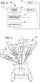
- FIG. 4 diagrammatically illustrates a robotic surgery system 50 (such as MIRS system 10 of FIG. 1 ) .
- a Surgeon's Console 52 (such as Surgeon's Console 16 in FIG. 1 ) can be used by a Surgeon to control a Patient Side Cart (Surgical Robot) 54 (such as Patent Side Cart 22 in FIG. 1 ) during a minimally invasive procedure.
- the Patient Side Cart 54 can use an imaging device, such as a stereoscopic endoscope, to capture images of the procedure site and output the captured images to an Electronics Cart 56 (such as the Electronics Cart 24 in FIG. 1 ).
- the Electronics Cart 56 can process the captured images in a variety of ways prior to any subsequent display.
- the Electronics Cart 56 can overlay the captured images with a virtual control interface prior to displaying the combined images to the Surgeon via the Surgeon's Console 52.
- the Patient Side Cart 54 can output the captured images for processing outside the Electronics Cart 56.
- the Patient Side Cart 54 can output the captured images to a processor 58, which can be used to process the captured images.
- the images can also be processed by a combination the Electronics Cart 56 and the processor 58, which can be coupled together to process the captured images jointly, sequentially, and/or combinations thereof.
- One or more separate displays 60 can also be coupled with the processor 58 and/or the Electronics Cart 56 for local and/or remote display of images, such as images of the procedure site, or other related images.
- FIG. 5 shows a Patient Side Cart 22.
- the Patient Side Cart 22 shown provides for the manipulation of three surgical tools 26 and an imaging device 28, such as a stereoscopic endoscope used for the capture of images of the site of the procedure. Manipulation is provided by robotic mechanisms having a number of robotic joints.
- the imaging device 28 and the surgical tools 26 can be positioned and manipulated through incisions in the patient so that a kinematic remote center is maintained at the incision to minimize the size of the incision.
- Images of the surgical site can include images of the distal ends of the surgical tools 26 when they are positioned within the field-of-view of the imaging device 28.
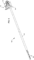
- FIG. 6 shows a robotic surgical tool 100, in accordance with many embodiments.
- the robotic surgical tool 100 is an example of the surgical tool 26.
- the surgical tool 100 includes an end effector 102, an elongated instrument shaft assembly 104, and a proximal assembly 106.
- the end effector 102 is supported by the instrument shaft assembly 104 at a distal end of the instrument shaft assembly 104.
- the proximal assembly 106 includes a proximal chassis 108 and an actuation portion 110 supported by the proximal chassis 108.
- the actuation portion 110 is configured to articulate actuation cables used to articulate an actuation rod assembly mounted to translate along a lumen of the instrument shaft assembly 104.
- the actuation rod assembly includes an actuation rod that is drivingly coupled with the end effector 102 to transfer push/pull actuation forces to the end effector 102.
- the push/pull actuation forces transferred to the end effector 102 can be used to actuate any suitable mechanism of the end effector 102, for example, a jaw articulation mechanism to clamp tissue, a staple deployment mechanism to deploy staples into clamped tissue, and/or a cutting mechanism to cut tissue clamped and stapled by the end effector 102.
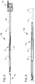
- FIG. 7A and FIG. 7B are simplified schematic diagrams illustrating the surgical tool 100.
- the surgical tool 100 includes a cable-driven mechanism 112 for transferring push/pull actuation force to the end effector 102.
- the cable-driven mechanism 112 includes an actuation rod assembly 114, a pulley assembly 116, an actuation cable 118, and an isolation tube 140.
- the actuation rod assembly 114 includes a shuttle 120 and an actuation rod 122 that is fixedly attached to the shuttle 120.
- the instrument shaft assembly 104 has a lumen 124 that extends from a proximal end 126 of the instrument shaft assembly 104 to a distal end 128 of the instrument shaft assembly 104.
- the instrument shaft assembly 104 is elongated along an instrument shaft axis 130.
- the shuttle 120 is disposed within the lumen 124 and mounted within the instrument shaft assembly 104 for translation along the lumen 124 parallel to the instrument shaft axis 130.
- the pulley assembly 116 includes a pulley 132 and a pulley support 134 that supports the pulley 132 and is coupled with the instrument shaft assembly 104.
- the actuation cable 118 is attached to the shuttle 120 at a connection 136.
- a first segment of the actuation cable 118 extends distally from the connection 136 to the pulley 132, is reeved around the pulley 132, extends proximally from the pulley 132 to a guide aperture 138 through a proximal portion of the shuttle 120, extends through the guide aperture 138, extends proximally from the guide aperture 138 to an isolation tube 140, extends through the isolation tube 140, extends proximally from the isolation tube 140 to a capstan 142 of the actuation portion 110, and is wrapped around the capstan 142 in a first direction.
- a second segment of the actuation cable 118 extends proximally from the connection 136 to the isolation tube 140, extends through the isolation tube 140, extends proximally from the isolation tube 140 to the capstan 142, and is wrapped around the capstan 142 in a second direction opposite to the first direction.
- Controlled rotation of the capstan 142 is used to control translation of the shuttle 120 along the lumen 124.
- counter-clockwise rotation of the capstan 142 pulls the first segment of the actuation cable 118 toward the capstan 142 (and accommodates distal advancement of the second segment of the actuation cable 118) thereby pulling the shuttle 120 distally toward the end effector 102.
- Pulling the shuttle 120 distally pushes the actuation rod 122 toward the end effector 102.
- the capstan 142 can be rotated to advance the shuttle 120 from the proximal position illustrated in FIG. 7A to the distal position illustrated in FIG. 7B , thereby distally advancing the actuation rod 122 through an actuation stroke.
- the capstan 142 can be rotated to retract the shuttle 120 from the distal position illustrated in FIG. 7B to the proximal position illustrated in FIG. 7A , thereby proximally retracting the actuation rod 122 through the actuation stroke.
- the shuttle 120 has a central slot configured to accommodate the pulley assembly 116 for all positions of the shuttle 120 from the proximal position illustrated in FIG. 7A to the distal position illustrated in FIG. 7B .
- the articulation of the actuation rod 122 can be used to transfer significant actuation force to the end effector 102 to actuate any suitable mechanism of the end effector 102.
- 7A can be used to articulate a jaw of the end effector to clamp tissue between the jaw and a replaceable stapler cartridge mounted to the end effector 102, articulate the stapler cartridge to deploy staples from the stapler cartridge into tissue clamped between the stapler cartridge and the jaw, and/or articulate a cutting element to cut tissue clamped between the stapler cartridge and the jaw and stapled via staples deployed from the stapler cartridge into the clamped tissue.
- the instrument shaft assembly 104 is mounted to the proximal assembly 106 for controlled rotation of the instrument shaft assembly 104 relative to the proximal chassis 108 around the instrument shaft axis 130.
- the shuttle 120 is mounted within the lumen 124 to rotate with the instrument shaft assembly 104.
- the isolation tube 140 is configured to enclose and/or constrain the location of at least a portion of the inter-twisted portions of the actuation cable 118.
- the isolation tube 140 can be used to isolate one or more other actuation members for the end effector that are disposed in the lumen 124 surrounding the isolation tube 140 from the inter-twisted portions of the actuation cable 118 to prevent the inter-twisting of the actuation cable 118 from interfering with the surrounding one or more other actuation members.
- FIG. 8 through FIG. 12 illustrate an embodiment of the surgical tool 100 of FIG. 7A and FIG. 7B .
- FIG. 8 shows embodiments of the end effector 102, a partial view of the instrument shaft assembly 104, the proximal assembly 106, the pulley assembly 116, the shuttle 120, the actuation rod 122, and the isolation tube 140.
- FIG. 9 is a plan view of the embodiment of the surgical tool 100 of FIG. 8 showing a partial view of the instrument shaft assembly 104, the pulley assembly 116, the shuttle 120, the actuation rod 122, and the isolation tube 140.
- FIG. 10 is a close-up view of the embodiment of the surgical tool 100 of FIG. 8 showing a first component 104(1) of the instrument shaft assembly 104, the pulley assembly 116, the shuttle 120, the actuation rod 122, the actuation cable 118, and the isolation tube 140.
- a mating second component of the instrument shaft assembly 104 is not shown in FIG. 10 .
- the instrument shaft assembly 104 includes the illustrated first component 104(1) and the mating second component of the instrument shaft assembly 104 (not shown in FIG.
- the shuttle 120 includes a first guide feature 144 that protrudes in a first direction and a second guide feature 146 that protrudes in a second direction different from the first direction.
- the second direction is in the opposite direction to the first direction.
- the first component 104(1) and the mating second component of the instrument shaft assembly 104 form a first slot 148 sized to accommodate the first guide feature 144 and a second slot 150 sized to accommodate the second guide feature 146 to constrain the shuttle 120 to translation along the instrument shaft axis 130 throughout the total range of movement of the shuttle 120 relative to the instrument shaft assembly 104.
- the first component 104(1) and the mating second component of the instrument shaft assembly 104 are also configured to enable installation of the pulley assembly 116 into the lumen 124 of the instrument shaft assembly 104.
- the first component 104(1) and the mating second component of the instrument shaft assembly 104 can include recesses configured to receive and interface with interfacing portions of the pulley support 134, thereby capturing and restraining the pulley support 134 within the lumen 124 of the instrument shaft assembly 104.
- the first component 104(1) and the mating second component of the instrument shaft assembly 104 are also configured to enable installation of the isolation tube 140 into the lumen 124 of the instrument shaft assembly 104.
- the first component 104(1) and the mating second component of the instrument shaft assembly 104 can include recesses configured to receive and interface with interfacing portions of the isolation tube 140, thereby capturing and restraining the isolation tube 140 within the lumen 124 of the instrument shaft assembly 104.
- FIG. 11 and FIG. 12 are views of the proximal assembly 106 of the surgical tool 100.
- the actuation cable 118 is reeved around the capstan 142.
- the capstan 142 is mounted for rotation about a capstan axis 152 that is perpendicular to the instrument shaft axis 130. Controlled rotation of the capstan 142 via an actuation input 154 controls extension and retraction of the first and second segments of the actuation cable 118 so as to control transfer of actuation force to the end effector 102 via the actuation rod 122.
- the capstan 142 includes an adjustment feature that is operable to adjust tension and/or remove slack from the actuation cable 118.
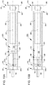
- FIG. 13A and FIG. 13B are simplified schematic diagrams illustrating a surgical tool 200.
- the surgical tool 200 is similar to the surgical tool 100, but instead of including the cable-driven mechanism 112, includes a band-driven mechanism 212 for transferring push/pull actuation force to the end effector 102.
- the band-driven mechanism 212 includes an actuation rod assembly 214, a drive band end support 216, a drive band 218, and an isolation tube 240.
- the actuation rod assembly 214 includes a shuttle 220 and an actuation rod 222 that is fixedly attached to the shuttle 220.
- the instrument shaft 204 has a lumen 224 that extends from a proximal end 226 of the instrument shaft 204 to a distal end 228 of the instrument shaft 204.
- the instrument shaft 204 is elongated along the instrument shaft axis 230.
- the shuttle 220 is disposed within the lumen 224 and coupled with the instrument shaft 204 for translation along the lumen 224 along the instrument shaft axis 230.
- the drive band end support 216 includes a drive band end support frame 234 that supports a first bearing 232a and a second bearing 232b.
- the drive band end support frame 234 is disposed within the lumen 224 and mounted to the instrument shaft 204.
- the drive band 218 is attached to the shuttle 220 at a connection 236.
- a first segment of the drive band 218 extends distally from the connection 236 to the first and second bearings 132a, 132b, is reeved around the first and second bearings 132a, 132b, extends proximally from the first and second bearings 132a, 132b to a guide aperture through the shuttle 220 on a side of the shuttle 220 opposite to the connection 236, extends through the guide aperture, extends proximally from the guide aperture to the isolation tube 240, extends through the isolation tube 240, extends proximally from the isolation tube 240 to a capstan 242 of the actuation portion 210, and is wrapped around the capstan 242 in a first direction.
- a second segment of the cable 218 extends proximally from the connection 236 to the isolation tube 240, extends through the isolation tube 240, extends proximally from the isolation tube 240 to the capstan 242, and is wrapped around the capstan 242 in a second direction opposite to the first direction.
- Controlled rotation of the capstan 242 is used to control translation of the shuttle 220 along the lumen 224.
- rotation of the capstan 242 in a first direction pulls the first segment of the drive band 218 toward the capstan 242 (and accommodates distal advancement of the second segment of the drive band 218) thereby pulling the shuttle 220 distally toward the end effector 102.
- Pulling the shuttle 220 distally pushes the actuation rod 222 toward the end effector 102.
- the capstan 242 can be rotated to advance the shuttle 220 from the proximal position illustrated in FIG. 13A to the distal position illustrated in FIG. 13B , thereby distally advancing the actuation rod 222 through an actuation stroke.
- capstan 242 can be rotated to retract the shuttle 220 from the distal position illustrated in FIG. 13B to the proximal position illustrated in FIG. 13A , thereby proximally retracting the actuation rod 222 through the actuation stroke.
- the articulation of the actuation rod 222 can be used to transfer significant actuation force to the end effector 102 to actuate any suitable mechanism of the end effector 102.
- 13A can be used to articulate a jaw of the end effector to clamp tissue between the jaw and a replaceable stapler cartridge mounted to the end effector 102, articulate the stapler cartridge to deploy staples from the stapler cartridge into tissue clamped between the stapler cartridge and the jaw, and/or articulate a cutting element to cut tissue clamped between the stapler cartridge and the jaw and stapled via staples deployed from the stapler cartridge into the clamped tissue.
- the instrument shaft 204 is mounted to the proximal assembly 206 for controlled rotation of the instrument shaft 204 relative to the proximal chassis 208 around the instrument shaft axis 230.
- the shuttle 220 is mounted within the lumen 224 to rotate with the instrument shaft 204.
- the isolation tube 240 is configured to enclose and/or constrain the location of at least a portion of the inter-twisted portions of the drive band 218.
- the isolation tube 240 can be used to isolate one or more other actuation members for the end effector 102 that are disposed in the lumen 224 surrounding the isolation tube 240 from the inter-twisted portions of the drive band 218 to prevent the inter-twisting of the drive band 218 from interfering with the surrounding one or more other actuation members.
- FIG. 14 through FIG. 17 illustrate an embodiment of the surgical tool 200 of FIG. 13A and FIG. 13B .
- FIG. 14 shows embodiments of the end effector 102, the instrument shaft 204, the proximal assembly 206, the drive band end support 216, the shuttle 220, the actuation rod 222, and the isolation tube 240.
- FIG. 15 is close-up view showing the shuttle 220, the drive band 218, the actuation rod 222, the first component 204(1) of an instrument shaft 204 (second component 204(2) of the instrument shaft 204 not shown in FIG. 15 ), and the connection 236 between the drive band 218 and the shuttle 220.
- connection 236 includes two protruding head bolts 237 that extend through respective holes in the drive band 218 and are mated with respective threaded holes in the shuttle 220, thereby securing the local portion of the drive band 218 to the shuttle 220.
- the instrument shaft 204 includes the illustrated first component 204(1) and the mating second component 204(2) of the instrument shaft 204 (not shown in FIG. 15 and shown in FIG. 16 ) to enable installation of the actuation rod assembly 214 (which includes the shuttle 220 and the actuation rod 222), the drive band end support 216, the isolation tube 240, and the drive band 218 into the lumen 224 of the instrument shaft 204.
- the shuttle 220 includes a first guide feature 244 that protrudes in a first direction and a second guide feature 246 (hidden from view in FIG. 15 ) that protrudes in a second direction different from the first direction.
- the second direction is in the opposite direction to the first direction.
- the first component 204(1) of the instrument shaft 204 has a first slot 248 sized to accommodate the second guide feature 246 and the second component 204(2) has a second slot 250 sized to accommodate the first guide feature 244 to constrain the shuttle 220 to translation along the instrument shaft axis 230 throughout the total range of movement of the shuttle 220 relative to the instrument shaft 204.
- the first component 204(1) and the mating second component 204(2) of the instrument shaft assembly 104 are also configured to enable installation of the drive band end support 216 into the lumen 224 of the instrument shaft 204.
- the first component 204(1) and the mating second component 204(2) of the instrument shaft 204 can include recesses configured to receive and interface with interfacing portions of a drive band end support frame 234, thereby capturing and restraining the drive band end support 216 within the lumen 224 of the instrument shaft 204.
- the first component 204(1) and the mating second component 204(2) of the instrument shaft 204 are also configured to enable installation of the isolation tube 240 into the lumen 224 of the instrument shaft 204.
- the first component 204(1) and the mating second component 204(2) of the instrument shaft 204 can include recesses configured to receive and interface with interfacing portions of the isolation tube 240, thereby capturing and restraining the isolation tube 240 within the lumen 224 of the instrument shaft 204.
- FIG. 16 is a close-up view showing the shuttle 220 and guide pins 238a, 238b that form a guide slot through which the drive band 218 extends. During actuation of the shuttle 220 via actuation of the drive band 218, the drive band 218 slides through the guide slot between the guide pins 238a, 238b and the shuttle 220. FIG. 16 also shows the second guide feature 246 and the second component 204(2) of the instrument shaft 204.
- FIG. 17 is a close-up view showing the drive band end support 216.
- the drive band end support 216 includes the drive band end support frame 234 and the first and second bearings 232a, 232b mounted on the drive band end support frame 234 for rotation about a drive band end support axis 252 perpendicular to the instrument shaft axis 230 and parallel to the side faces of the drive band 218.
- the drive band end support frame 234 has an aperture 254 sized to accommodate the actuation rod 222, which extends through the aperture 254.
- the drive band end support frame 234 includes first and second end journals 256, 258 that mate with complementary-shaped recesses in the instrument shaft 204 to support the drive band end support frame 234 at a fixed location within the lumen 224 of the instrument shaft 204.
Landscapes
- Health & Medical Sciences (AREA)
- Surgery (AREA)
- Life Sciences & Earth Sciences (AREA)
- Engineering & Computer Science (AREA)
- Medical Informatics (AREA)
- General Health & Medical Sciences (AREA)
- Biomedical Technology (AREA)
- Heart & Thoracic Surgery (AREA)
- Nuclear Medicine, Radiotherapy & Molecular Imaging (AREA)
- Molecular Biology (AREA)
- Animal Behavior & Ethology (AREA)
- Veterinary Medicine (AREA)
- Public Health (AREA)
- Robotics (AREA)
- Ophthalmology & Optometry (AREA)
- Oral & Maxillofacial Surgery (AREA)
- Pathology (AREA)
- Surgical Instruments (AREA)
- Manipulator (AREA)
Description
- Minimally invasive surgical techniques are aimed at reducing the amount of extraneous tissue damaged during diagnostic or surgical procedures, thereby reducing patient recovery time, discomfort, and deleterious side effects. As a consequence, the average length of a hospital stay for standard surgery may be shortened significantly using minimally invasive surgical techniques. Also, patient recovery times, patient discomfort, surgical side effects, and time away from work may also be reduced with minimally invasive surgery.
- A common form of minimally invasive surgery is endoscopy, and a common form of endoscopy is laparoscopy, which is minimally invasive inspection and surgery inside the abdominal cavity. In standard laparoscopic surgery, a patient's abdomen is insufflated with gas, and cannula sleeves are passed through small (approximately one-half inch (1.27 cm) or less) incisions to provide entry ports for laparoscopic instruments.
- Laparoscopic surgical instruments generally include an endoscope (e.g., laparoscope) for viewing the surgical field and tools for working at the surgical site. The working tools are typically similar to those used in conventional (open) surgery, except that the working end or end effector of each tool is separated from its handle by an extension tube (also known as, e.g., an instrument shaft or a main shaft). The end effector can include, for example, a clamp, grasper, scissor, stapler, cautery tool, linear cutter, or needle holder.
- To perform surgical procedures, the surgeon passes working tools through cannula sleeves to an internal surgical site and manipulates them from outside the abdomen. The surgeon views the procedure from a monitor that displays an image of the surgical site taken from the endoscope. Similar endoscopic techniques are employed in, for example, arthroscopy, retroperitoneoscopy, pelviscopy, nephroscopy, cystoscopy, cisternoscopy, sinoscopy, hysteroscopy, urethroscopy, and the like.
- Minimally invasive telesurgical robotic systems are being developed to increase a surgeon's dexterity when working on an internal surgical site, as well as to allow a surgeon to operate on a patient from a remote location (outside the sterile field). In a telesurgery system, the surgeon is often provided with an image of the surgical site at a control console. While viewing a three dimensional image of the surgical site on a suitable viewer or display, the surgeon performs the surgical procedures on the patient by manipulating master input or control devices of the control console. Each of the master input devices controls the motion of a servo-mechanically actuated/articulated surgical instrument. During the surgical procedure, the telesurgical system can provide mechanical actuation and control of a variety of surgical instruments or tools having end effectors that perform various functions for the surgeon, for example, holding or driving a needle, grasping a blood vessel, dissecting tissue, or the like, in response to manipulation of the master input devices.
- Surgical clamping and cutting tools (e.g., non-robotic linear clamping, stapling, and cutting devices, also known as surgical staplers; and electrosurgical vessel sealing devices) have been employed in many different surgical procedures. For example, a surgical stapler can be used to resect a cancerous or anomalous tissue from a gastro-intestinal tract. Many known surgical clamping and cutting devices, including known surgical staplers, have opposing jaws that clamp tissue and an articulated knife to cut the clamped tissue.
- A surgical clamping and cutting tool can include an instrument shaft supported end effector to which a replaceable stapler cartridge is mounted. A jaw of the end effector can be articulated to clamp tissue between the stapler cartridge and the jaw. The stapler cartridge can then be articulated to deploy staples from the stapler cartridge to staple tissue clamped between the stapler cartridge and the jaw. The stapler cartridge can include a knife that is articulable to cut the stapled tissue between rows of deployed staples.
- The actuation force levels sufficient to clamp, staple, and/or cut tissue can be significant. Moreover, it is desirable to limit the diameter of an instrument shaft supporting the end effector and to actuate the end effector via a proximal actuation portion that is drivingly coupled with the end effector via a linkage extending through the instrument shaft. It is also desirable that a linkage extending through a small diameter instrument shaft to drivingly coupled an end effector with a proximal actuation portion be robust, affordable, and reliable. The surgical tools and related methods presented herein are suitable to transfer sufficient actuation forces to an end effector, such as a clamping, stapling, and cutting end effector through a relatively small-diameter instrument shaft in a robust, affordable, and reliable manner.
-
US 2003/135204 discloses a robotically controlled medical instrument that includes a bending section with a unibody construction, a tool supported at a distal end of the bending section and used to perform a medical procedure on a subject such as a human patient, and an electronic controller that controls the bending section to provide at least one degree-of-freedom of movement..US 2010/076461 discloses a handle assembly for operating a surgical instrument and includes a housing; a trigger operatively supported on the housing; and at least one actuation cable operatively associated with the trigger and extending from the housing in such a manner that an actuation of the trigger imparts both an axial translation of the actuation cable and a rotation to the actuation cable.WO 2016/067436 discloses a medical treatment tool having a long flexible section. A wire passes through the flexible section along the longitudinal axis. To a leading end of the flexible section, a pair of jaws are mounted via a movable member. When a basal end of the wire is pulled, the leading end of the wire pulls a pin and the pin closes the pair of jaws so that the jaws hold a tissue.US 2015/352715 discloses a manipulator that includes an elongated main portion, a distal end portion, and a bendable portion provided between the main portion and the distal end portion; a plurality of linear members that extend from the distal end portion to the main portion via the bendable portion; a power generator; a plurality of power transmitters that transmit, to proximal ends of the linear members, the power generated by the power generator as linear motion in a longitudinal direction of the main portion; and a linear-member relaxing unit that relaxes the linear members in which tension is generated between the distal end portion and the power transmitters by pushing and pulling of the linear members by the linear motion transmitted from the power transmitters. - The invention is as defined in
independent claim 1. Dependent claims 2-9 disclose exemplary embodiments. Surgical tools and related methods are provided in which proximal retraction of a flexible tension member is used to transfer a distally-directed actuation force through an instrument shaft assembly to an end effector supported by the instrument shaft assembly. The flexible tension member is wrapped around a guide surface disposed within the instrument shaft assembly and connected to an actuation rod assembly that is moved toward the end effector in response to the retraction of the flexible tension member. The actuation rod assembly, the guide surface, and the flexible tension member are configured to be enclosed within an elongated, relatively small-diameter instrument shaft assembly and to transfer a distally-directed actuation force to actuate a surgical end effector, such as a clamping, stapling, and cutting surgical end effector. - Thus, according to the invention, a surgical tool is provided. The surgical tool includes an actuation portion, an end effector, an instrument shaft assembly coupling the actuation portion to the end effector, an actuation rod assembly drivingly coupled with the end effector, and a flexible tension member. The instrument shaft assembly is elongated along an instrument shaft axis and defines a lumen. The instrument shaft assembly includes a guide surface disposed towards a distal end of the lumen. The actuation rod assembly is slideably mounted within the lumen for translation relative to the instrument shaft assembly along the instrument shaft axis. The flexible tension member drivingly couples the actuation portion to the actuation rod assembly. The flexible tension member is connected to the actuation rod assembly at a connection that is longitudinally disposed between the actuation portion and the guide surface. The flexible tension member includes a first portion that, from the connection, extends distally towards the guide surface, wraps around the guide surface, and extends proximally towards the actuation portion. The flexible tension member includes a second portion that, from the connection, extends proximally towards the actuation portion. The actuation portion is operable to increase tension in the first portion of the flexible tension member to translate the actuation rod assembly in a distal direction and to increase tension in the second portion of the flexible tension member to translate the actuation rod assembly in a proximal direction.
- In many embodiments, the actuation portion is operable to rotate the instrument shaft assembly around the instrument shaft axis relative to a proximal chassis supporting the instrument shaft assembly. In many embodiments, the actuation rod assembly is constrained to rotate with the instrument shaft assembly around the instrument shaft axis. The surgical tool can include an isolation tube extending along the instrument shaft axis. The isolation tube can be disposed between the connection and the actuation portion. The first and second portions of the flexible tension member can pass through the isolation tube. The isolation tube can enclose an inter-twistable length of the first and second portions and isolate the inter-twistable length from a region of the lumen surrounding the isolation tube. Accordingly, one or more additional actuation members for actuating and/or articulating the end effector can be routed through the region of the lumen surrounding the isolation tube and thereby be kept from being detrimentally impacted as a result of inter-twisting of the first and second portions resulting from rotation of the instrument shaft assembly.
- The flexible tension member can include any suitable flexible tension member. For example, the flexible tension member can include an actuation cable. The first portion of the flexible tension member can include a first length of cable and the second portion of the flexible tension member can include a second length of cable. The surgical tool can include a pulley that includes the guide surface. The actuation portion can be operable to move the actuation rod assembly through a range of movement relative to the pulley. The actuation rod assembly can include a slot configured to accommodate the pulley throughout the range of movement. The actuation rod assembly can include a cable guide aperture through which the second length of cable extends.
- In many embodiments, the instrument shaft assembly includes separate components (e.g., separate upper and lower half segments) that accommodate installation of the actuation rod assembly, the guide surface, and the flexible tension member into the lumen of the instrument shaft assembly, and joinable to form the lumen enclosing the actuation rod assembly, the guide surface, and the flexible tension member. For example, the instrument shaft assembly can include a first component and a second component. The first and second components can be configured to accommodate insertion of the actuation rod assembly, the guide surface, and the flexible tension member into the lumen when the first and second components are uncoupled. The first and second components can be configured to be joined to form the lumen.
- In many embodiments, the actuation portion is operable to move the actuation rod assembly through a range of movement relative to the guide surface. The actuation rod assembly can include a first guide feature that protrudes in a first direction and a second guide feature protrudes in a second direction different than the first direction. The first component and the second component can form a first slot sized to accommodate the first guide feature and a second slot sized to accommodate the second guide feature throughout the range of movement.
- The flexible tension member can include suitable flexible tension members other than a cable. For example, the flexible tension member can include a drive band. The drive band can include a slot through which a portion of the actuation rod assembly between the connection and the end effector extends. The surgical tool can include a support frame, a first bearing, and a second bearing. The support frame can have an aperture through which the portion of the actuation rod assembly between the connection and the end effector extends. The first bearing can be mounted to the support frame to rotate around a guide surface axis perpendicular to the instrument shaft axis and interface with the drive band on a first side of the slot. The second bearing can be mounted to the support frame to rotate around the guide surface axis and interface with the drive band on a second side of the slot opposite to the first side of the slot. The actuation rod assembly can include a drive band guide aperture through which the drive band extends.
- In another aspect not according to the invention, a method is provided for actuating an end effector of a surgical tool. The method includes supporting an end effector via an instrument shaft assembly elongated along an instrument shaft axis, enclosing an actuation rod assembly within a lumen of the instrument shaft assembly, guiding the actuation rod assembly during movement of the actuation rod assembly along the instrument shaft axis, and operating an actuation portion to increase tension in a first portion of a flexible tension member drivingly coupled with the actuation rod assembly to move the actuation rod assembly toward the end effector to actuate the end effector. The first portion of the flexible tension member extends distally from the actuation portion to a guide surface, is wrapped around the guide surface, and extends from the guide surface to a connection between the first portion of the flexible tension member and the actuation rod assembly. In many examples, the method further includes operating the actuation portion to increase tension in a second portion of the flexible tension member drivingly coupled with the actuation rod assembly to move the actuation rod assembly away from the end effector.
- In many examples not according to the invention, the method includes operating the actuation portion to rotate the instrument shaft assembly around the instrument shaft axis relative to a proximal chassis supporting the instrument shaft assembly. The method can include constraining the actuation rod assembly to rotate with the instrument shaft assembly around the instrument shaft axis. The method can include enclosing an inter-twistable length of the first and second portions of the flexible tension member disposed between the actuation rod assembly and the actuation portion within an isolation tube to isolate the inter-twistable length from a region of the lumen surrounding the isolation tube.
- In many examples of the method, not according to the invention, the flexible tension member includes a cable. For example, the first portion of the flexible tension member can include a first length of cable. The second portion of the flexible tension member can include a second length of cable. The surgical tool can include a pulley that includes the guide surface. The method can include operating the actuation portion to move the actuation rod assembly through a range of movement relative to the pulley and accommodating the pulley within a slot of the actuation rod assembly throughout the range of movement. The method can include guiding the second length of cable via a cable guide aperture in the actuation rod assembly through which the second length of cable extends.
- In many examples of the method not according to the invention, the instrument shaft assembly includes separate components (e.g, separate upper and lower half segments) that accommodate installation of the actuation rod assembly, the guide surface, and the flexible tension member into the lumen of the instrument shaft assembly, and joinable to form the lumen enclosing the actuation rod assembly, the guide surface, and the flexible tension member. For example, the method can include inserting the actuation rod assembly, the guide surface, and the flexible tension member into a first component of the instrument shaft assembly and coupling a second component of the instrument shaft assembly to the first component to enclose the actuation rod assembly, the guide surface, and a portion of the flexible tension member within the lumen of the instrument shaft assembly.
- In many examples not according to the invention, the method includes operating the actuation portion to move the actuation rod assembly through a range of movement relative to the guide surface. The method can include interfacing protruding guide features of the actuation rod assembly with the instrument shaft assembly to guide movement of the actuation rod assembly relative to the instrument shaft assembly through the range of movement.
- In many examples of the method not according to the invention, the flexible tension member can include suitable flexible tension members other than a cable. For example, the flexible tension member can include a drive band. The method can include accommodating a portion of the actuation rod assembly between the connection and the end effector through a slot in the drive band. The method can include accommodating a portion of the actuation rod extending between the connection and the end effector in an aperture of a support frame, supporting a first bearing mounted to the support frame to rotate around a guide surface axis perpendicular to the instrument shaft axis and interface with the drive band on a first side of the slot, and supporting a second bearing mounted to the support frame to rotate around the guide surface axis and interface with the drive band on a second side of the slot opposite to the first side of the slot. In many examples, the first and second bearings include the guide surface. The method can include guiding the drive band via a drive band guide aperture of the actuation rod assembly through which the drive band extends.
- For a fuller understanding of the nature and advantages of the present invention, reference should be made to the ensuing detailed description and accompanying drawings. Other aspects, objects and advantages of the invention will be apparent from the drawings and detailed description that follows.
-
-
FIG. 1 is a plan view of a minimally invasive robotic surgery system being used to perform a surgery, in accordance with many embodiments. -
FIG. 2 is a perspective view of a surgeon's control console for a robotic surgery system, in accordance with many embodiments. -
FIG. 3 is a perspective view of a robotic surgery system electronics cart, in accordance with many embodiments. -
FIG. 4 diagrammatically illustrates a robotic surgery system, in accordance with many embodiments. -
FIG. 5 is a front view of a patient side cart (surgical robot) of a robotic surgery system, in accordance with many embodiments. -
FIG. 6 shows a robotic surgical tool, in accordance with many embodiments. -
FIG. 7A and FIG. 7B are simplified schematic diagrams illustrating a surgical tool that includes an end effector and a cable-driven mechanism for transferring push/pull actuation forces to the end effector, in accordance with many embodiments. -
FIG. 8 is a plan view of an embodiment of the surgical tool ofFIG. 7A and FIG. 7B . -
FIG. 9 is a plan view showing components of the cable-driven mechanism for transferring push/pull actuation forces to the end effector of the surgical tool ofFIG. 8 . -
FIG. 10 is a close-up view showing components of the cable-driven mechanism for transferring push/pull actuation forces to the end effector of the surgical tool ofFIG. 8 . -
FIG. 11 andFIG. 12 are views of a proximal actuation mechanism operable to actuate the cables of the cable-driven mechanism for transferring push/pull actuation forces to the end effector of the surgical tool ofFIG. 8 . -
FIG. 13A and FIG. 13B are simplified schematic diagrams illustrating a surgical tool that includes an end effector and a band-driven mechanism for transferring push/pull actuation forces to the end effector, in accordance with many embodiments. -
FIG. 14 is a plan view of an embodiment of the surgical tool ofFIG. 13A and FIG. 13B . -
FIG. 15 and FIG. 16 are close-up views showing a band-driven shuttle of the band-driven mechanism for transferring push/pull actuation forces to the end effector of the surgical tool ofFIG. 14 . -
FIG. 17 is a close-up view showing a drive band end support of the band-driven mechanism for transferring push/pull actuation forces to the end effector of the surgical tool ofFIG. 14 . - In the following description, various embodiments of the present invention will be described. For purposes of explanation, specific configurations and details are set forth in order to provide a thorough understanding of the embodiments. However, it will also be apparent to one skilled in the art that the present invention may be practiced without the specific details. Furthermore, well-known features may be omitted or simplified in order not to obscure the embodiment being described.
- Referring now to the drawings, in which like reference numerals represent like parts throughout the several views,
FIG. 1 is a plan view illustration of a Minimally Invasive Robotic Surgical (MIRS)system 10, typically used for performing a minimally invasive diagnostic or surgical procedure on aPatient 12 who is lying down on an Operating table 14. The system can include a Surgeon'sConsole 16 for use by aSurgeon 18 during the procedure. One ormore Assistants 20 may also participate in the procedure. TheMIRS system 10 can further include a Patient Side Cart 22 (surgical robot) and anElectronics Cart 24. ThePatient Side Cart 22 can manipulate at least one removably coupled tool assembly 26 (hereinafter simply referred to as a "tool") through a minimally invasive incision in the body of thePatient 12 while theSurgeon 18 views the surgical site through theConsole 16. An image of the surgical site can be obtained by anendoscope 28, such as a stereoscopic endoscope, which can be manipulated by thePatient Side Cart 22 to orient theendoscope 28. TheElectronics Cart 24 can be used to process the images of the surgical site for subsequent display to theSurgeon 18 through the Surgeon'sConsole 16. The number ofsurgical tools 26 used at one time will generally depend on the diagnostic or surgical procedure and the space constraints within the operating room among other factors. If it is necessary to change one or more of thetools 26 being used during a procedure, anAssistant 20 may remove thetool 26 from thePatient Side Cart 22, and replace it with anothertool 26 from atray 30 in the operating room. -
FIG. 2 is a perspective view of the Surgeon'sConsole 16. The Surgeon'sConsole 16 includes aleft eye display 32 and aright eye display 34 for presenting theSurgeon 18 with a coordinated stereo view of the surgical site that enables depth perception. TheConsole 16 further includes one or moreinput control devices 36, which in turn cause the Patient Side Cart 22 (shown inFIG. 1 ) to manipulate one or more tools. Theinput control devices 36 can provide the same degrees of freedom as their associated tools 26 (shown inFIG. 1 ) to provide the Surgeon with telepresence, or the perception that theinput control devices 36 are integral with thetools 26 so that the Surgeon has a strong sense of directly controlling thetools 26. To this end, position, force, and tactile feedback sensors (not shown) may be employed to transmit position, force, and tactile sensations from thetools 26 back to the Surgeon's hands through theinput control devices 36. - The Surgeon's
Console 16 is usually located in the same room as the patient so that the Surgeon may directly monitor the procedure, be physically present if necessary, and speak to an Assistant directly rather than over the telephone or other communication medium. However, the Surgeon can be located in a different room, a completely different building, or other remote location from the Patient allowing for remote surgical procedures. -
FIG. 3 is a perspective view of theElectronics Cart 24. TheElectronics Cart 24 can be coupled with theendoscope 28 and can include a processor to process captured images for subsequent display, such as to a Surgeon on the Surgeon's Console, or on another suitable display located locally and/or remotely. For example, where a stereoscopic endoscope is used, theElectronics Cart 24 can process the captured images to present the Surgeon with coordinated stereo images of the surgical site. Such coordination can include alignment between the opposing images and can include adjusting the stereo working distance of the stereoscopic endoscope. As another example, image processing can include the use of previously determined camera calibration parameters to compensate for imaging errors of the image capture device, such as optical aberrations. -
FIG. 4 diagrammatically illustrates a robotic surgery system 50 (such asMIRS system 10 ofFIG. 1 ). As discussed above, a Surgeon's Console 52 (such as Surgeon'sConsole 16 inFIG. 1 ) can be used by a Surgeon to control a Patient Side Cart (Surgical Robot) 54 (such asPatent Side Cart 22 inFIG. 1 ) during a minimally invasive procedure. ThePatient Side Cart 54 can use an imaging device, such as a stereoscopic endoscope, to capture images of the procedure site and output the captured images to an Electronics Cart 56 (such as theElectronics Cart 24 inFIG. 1 ). As discussed above, theElectronics Cart 56 can process the captured images in a variety of ways prior to any subsequent display. For example, theElectronics Cart 56 can overlay the captured images with a virtual control interface prior to displaying the combined images to the Surgeon via the Surgeon'sConsole 52. ThePatient Side Cart 54 can output the captured images for processing outside theElectronics Cart 56. For example, thePatient Side Cart 54 can output the captured images to aprocessor 58, which can be used to process the captured images. The images can also be processed by a combination theElectronics Cart 56 and theprocessor 58, which can be coupled together to process the captured images jointly, sequentially, and/or combinations thereof. One or moreseparate displays 60 can also be coupled with theprocessor 58 and/or theElectronics Cart 56 for local and/or remote display of images, such as images of the procedure site, or other related images. -
FIG. 5 shows aPatient Side Cart 22. ThePatient Side Cart 22 shown provides for the manipulation of threesurgical tools 26 and animaging device 28, such as a stereoscopic endoscope used for the capture of images of the site of the procedure. Manipulation is provided by robotic mechanisms having a number of robotic joints. Theimaging device 28 and thesurgical tools 26 can be positioned and manipulated through incisions in the patient so that a kinematic remote center is maintained at the incision to minimize the size of the incision. Images of the surgical site can include images of the distal ends of thesurgical tools 26 when they are positioned within the field-of-view of theimaging device 28. -
FIG. 6 shows a roboticsurgical tool 100, in accordance with many embodiments. The roboticsurgical tool 100 is an example of thesurgical tool 26. Thesurgical tool 100 includes anend effector 102, an elongatedinstrument shaft assembly 104, and aproximal assembly 106. Theend effector 102 is supported by theinstrument shaft assembly 104 at a distal end of theinstrument shaft assembly 104. Theproximal assembly 106 includes aproximal chassis 108 and anactuation portion 110 supported by theproximal chassis 108. Theactuation portion 110 is configured to articulate actuation cables used to articulate an actuation rod assembly mounted to translate along a lumen of theinstrument shaft assembly 104. The actuation rod assembly includes an actuation rod that is drivingly coupled with theend effector 102 to transfer push/pull actuation forces to theend effector 102. The push/pull actuation forces transferred to theend effector 102 can be used to actuate any suitable mechanism of theend effector 102, for example, a jaw articulation mechanism to clamp tissue, a staple deployment mechanism to deploy staples into clamped tissue, and/or a cutting mechanism to cut tissue clamped and stapled by theend effector 102. -
FIG. 7A and FIG. 7B are simplified schematic diagrams illustrating thesurgical tool 100. Thesurgical tool 100 includes a cable-drivenmechanism 112 for transferring push/pull actuation force to theend effector 102. The cable-drivenmechanism 112 includes anactuation rod assembly 114, apulley assembly 116, anactuation cable 118, and anisolation tube 140. Theactuation rod assembly 114 includes ashuttle 120 and anactuation rod 122 that is fixedly attached to theshuttle 120. Theinstrument shaft assembly 104 has alumen 124 that extends from aproximal end 126 of theinstrument shaft assembly 104 to adistal end 128 of theinstrument shaft assembly 104. Theinstrument shaft assembly 104 is elongated along aninstrument shaft axis 130. Theshuttle 120 is disposed within thelumen 124 and mounted within theinstrument shaft assembly 104 for translation along thelumen 124 parallel to theinstrument shaft axis 130. Thepulley assembly 116 includes apulley 132 and apulley support 134 that supports thepulley 132 and is coupled with theinstrument shaft assembly 104. Theactuation cable 118 is attached to theshuttle 120 at aconnection 136. A first segment of theactuation cable 118 extends distally from theconnection 136 to thepulley 132, is reeved around thepulley 132, extends proximally from thepulley 132 to aguide aperture 138 through a proximal portion of theshuttle 120, extends through theguide aperture 138, extends proximally from theguide aperture 138 to anisolation tube 140, extends through theisolation tube 140, extends proximally from theisolation tube 140 to acapstan 142 of theactuation portion 110, and is wrapped around thecapstan 142 in a first direction. A second segment of theactuation cable 118 extends proximally from theconnection 136 to theisolation tube 140, extends through theisolation tube 140, extends proximally from theisolation tube 140 to thecapstan 142, and is wrapped around thecapstan 142 in a second direction opposite to the first direction. - Controlled rotation of the
capstan 142 is used to control translation of theshuttle 120 along thelumen 124. In the illustrated embodiment, counter-clockwise rotation of thecapstan 142 pulls the first segment of theactuation cable 118 toward the capstan 142 (and accommodates distal advancement of the second segment of the actuation cable 118) thereby pulling theshuttle 120 distally toward theend effector 102. Pulling theshuttle 120 distally pushes theactuation rod 122 toward theend effector 102. For example, thecapstan 142 can be rotated to advance theshuttle 120 from the proximal position illustrated inFIG. 7A to the distal position illustrated inFIG. 7B , thereby distally advancing theactuation rod 122 through an actuation stroke. In a similar manner, thecapstan 142 can be rotated to retract theshuttle 120 from the distal position illustrated inFIG. 7B to the proximal position illustrated inFIG. 7A , thereby proximally retracting theactuation rod 122 through the actuation stroke. In the illustrated embodiment, theshuttle 120 has a central slot configured to accommodate thepulley assembly 116 for all positions of theshuttle 120 from the proximal position illustrated inFIG. 7A to the distal position illustrated inFIG. 7B . - The articulation of the
actuation rod 122 can be used to transfer significant actuation force to theend effector 102 to actuate any suitable mechanism of theend effector 102. For example, articulation of theactuation rod 122 from the proximal position illustrated inFIG. 7A to the distal position illustrated inFIG. 7B and/or from the distal position illustrated inFIG. 7B to the proximal position illustrated inFIG. 7A can be used to articulate a jaw of the end effector to clamp tissue between the jaw and a replaceable stapler cartridge mounted to theend effector 102, articulate the stapler cartridge to deploy staples from the stapler cartridge into tissue clamped between the stapler cartridge and the jaw, and/or articulate a cutting element to cut tissue clamped between the stapler cartridge and the jaw and stapled via staples deployed from the stapler cartridge into the clamped tissue. - In many embodiments, the
instrument shaft assembly 104 is mounted to theproximal assembly 106 for controlled rotation of theinstrument shaft assembly 104 relative to theproximal chassis 108 around theinstrument shaft axis 130. In many embodiments, theshuttle 120 is mounted within thelumen 124 to rotate with theinstrument shaft assembly 104. As a result of the rotation of theshuttle 120 with rotation of theinstrument shaft assembly 104, a portion of the second segment of the actuation cable 118 (extends proximally from theconnection 136 to the capstan 142) and a portion of the first segment of theactuation cable 118 that extends proximally from theguide aperture 138 to thecapstan 142 will inter-twist in accordance with the amount of rotation of theinstrument shaft assembly 104 relative to theproximal chassis 108. In many embodiments, theisolation tube 140 is configured to enclose and/or constrain the location of at least a portion of the inter-twisted portions of theactuation cable 118. Theisolation tube 140 can be used to isolate one or more other actuation members for the end effector that are disposed in thelumen 124 surrounding theisolation tube 140 from the inter-twisted portions of theactuation cable 118 to prevent the inter-twisting of theactuation cable 118 from interfering with the surrounding one or more other actuation members. -
FIG. 8 through FIG. 12 illustrate an embodiment of thesurgical tool 100 ofFIG. 7A and FIG. 7B .FIG. 8 shows embodiments of theend effector 102, a partial view of theinstrument shaft assembly 104, theproximal assembly 106, thepulley assembly 116, theshuttle 120, theactuation rod 122, and theisolation tube 140.FIG. 9 is a plan view of the embodiment of thesurgical tool 100 ofFIG. 8 showing a partial view of theinstrument shaft assembly 104, thepulley assembly 116, theshuttle 120, theactuation rod 122, and theisolation tube 140. -
FIG. 10 is a close-up view of the embodiment of thesurgical tool 100 ofFIG. 8 showing a first component 104(1) of theinstrument shaft assembly 104, thepulley assembly 116, theshuttle 120, theactuation rod 122, theactuation cable 118, and theisolation tube 140. A mating second component of theinstrument shaft assembly 104 is not shown inFIG. 10 . In the illustrated embodiment, theinstrument shaft assembly 104 includes the illustrated first component 104(1) and the mating second component of the instrument shaft assembly 104 (not shown inFIG. 10 ) to enable installation of the actuation rod assembly 114 (which includes theshuttle 120 and the actuation rod 122), thepulley assembly 116, theisolation tube 140, and theactuation cable 118 into thelumen 124 of theinstrument shaft assembly 104. In the illustrated embodiment, theshuttle 120 includes afirst guide feature 144 that protrudes in a first direction and asecond guide feature 146 that protrudes in a second direction different from the first direction. In the illustrated embodiment, the second direction is in the opposite direction to the first direction. The first component 104(1) and the mating second component of theinstrument shaft assembly 104 form afirst slot 148 sized to accommodate thefirst guide feature 144 and asecond slot 150 sized to accommodate thesecond guide feature 146 to constrain theshuttle 120 to translation along theinstrument shaft axis 130 throughout the total range of movement of theshuttle 120 relative to theinstrument shaft assembly 104. The first component 104(1) and the mating second component of theinstrument shaft assembly 104 are also configured to enable installation of thepulley assembly 116 into thelumen 124 of theinstrument shaft assembly 104. For example, the first component 104(1) and the mating second component of theinstrument shaft assembly 104 can include recesses configured to receive and interface with interfacing portions of thepulley support 134, thereby capturing and restraining thepulley support 134 within thelumen 124 of theinstrument shaft assembly 104. In a similar fashion, the first component 104(1) and the mating second component of theinstrument shaft assembly 104 are also configured to enable installation of theisolation tube 140 into thelumen 124 of theinstrument shaft assembly 104. For example, the first component 104(1) and the mating second component of theinstrument shaft assembly 104 can include recesses configured to receive and interface with interfacing portions of theisolation tube 140, thereby capturing and restraining theisolation tube 140 within thelumen 124 of theinstrument shaft assembly 104. -
FIG. 11 andFIG. 12 are views of theproximal assembly 106 of thesurgical tool 100. Theactuation cable 118 is reeved around thecapstan 142. Thecapstan 142 is mounted for rotation about acapstan axis 152 that is perpendicular to theinstrument shaft axis 130. Controlled rotation of thecapstan 142 via anactuation input 154 controls extension and retraction of the first and second segments of theactuation cable 118 so as to control transfer of actuation force to theend effector 102 via theactuation rod 122. In the illustrated embodiment, thecapstan 142 includes an adjustment feature that is operable to adjust tension and/or remove slack from theactuation cable 118. -
FIG. 13A and FIG. 13B are simplified schematic diagrams illustrating asurgical tool 200. Thesurgical tool 200 is similar to thesurgical tool 100, but instead of including the cable-drivenmechanism 112, includes a band-drivenmechanism 212 for transferring push/pull actuation force to theend effector 102. The band-drivenmechanism 212 includes anactuation rod assembly 214, a driveband end support 216, adrive band 218, and anisolation tube 240. Theactuation rod assembly 214 includes ashuttle 220 and anactuation rod 222 that is fixedly attached to theshuttle 220. Theinstrument shaft 204 has alumen 224 that extends from aproximal end 226 of theinstrument shaft 204 to adistal end 228 of theinstrument shaft 204. Theinstrument shaft 204 is elongated along theinstrument shaft axis 230. Theshuttle 220 is disposed within thelumen 224 and coupled with theinstrument shaft 204 for translation along thelumen 224 along theinstrument shaft axis 230. The driveband end support 216 includes a drive bandend support frame 234 that supports afirst bearing 232a and asecond bearing 232b. The drive bandend support frame 234 is disposed within thelumen 224 and mounted to theinstrument shaft 204. Thedrive band 218 is attached to theshuttle 220 at aconnection 236. A first segment of thedrive band 218 extends distally from theconnection 236 to the first and second bearings 132a, 132b, is reeved around the first and second bearings 132a, 132b, extends proximally from the first and second bearings 132a, 132b to a guide aperture through theshuttle 220 on a side of theshuttle 220 opposite to theconnection 236, extends through the guide aperture, extends proximally from the guide aperture to theisolation tube 240, extends through theisolation tube 240, extends proximally from theisolation tube 240 to acapstan 242 of theactuation portion 210, and is wrapped around thecapstan 242 in a first direction. A second segment of thecable 218 extends proximally from theconnection 236 to theisolation tube 240, extends through theisolation tube 240, extends proximally from theisolation tube 240 to thecapstan 242, and is wrapped around thecapstan 242 in a second direction opposite to the first direction. - Controlled rotation of the
capstan 242 is used to control translation of theshuttle 220 along thelumen 224. In the illustrated embodiment, rotation of thecapstan 242 in a first direction pulls the first segment of thedrive band 218 toward the capstan 242 (and accommodates distal advancement of the second segment of the drive band 218) thereby pulling theshuttle 220 distally toward theend effector 102. Pulling theshuttle 220 distally pushes theactuation rod 222 toward theend effector 102. For example, thecapstan 242 can be rotated to advance theshuttle 220 from the proximal position illustrated inFIG. 13A to the distal position illustrated inFIG. 13B , thereby distally advancing theactuation rod 222 through an actuation stroke. In a similar manner, thecapstan 242 can be rotated to retract theshuttle 220 from the distal position illustrated inFIG. 13B to the proximal position illustrated inFIG. 13A , thereby proximally retracting theactuation rod 222 through the actuation stroke. - The articulation of the
actuation rod 222 can be used to transfer significant actuation force to theend effector 102 to actuate any suitable mechanism of theend effector 102. For example, articulation of theactuation rod 222 from the proximal position illustrated inFIG. 13A to the distal position illustrated inFIG. 13B and/or from the distal position illustrated inFIG. 13B to the proximal position illustrated inFIG. 13A can be used to articulate a jaw of the end effector to clamp tissue between the jaw and a replaceable stapler cartridge mounted to theend effector 102, articulate the stapler cartridge to deploy staples from the stapler cartridge into tissue clamped between the stapler cartridge and the jaw, and/or articulate a cutting element to cut tissue clamped between the stapler cartridge and the jaw and stapled via staples deployed from the stapler cartridge into the clamped tissue. - In the illustrated embodiment, the
instrument shaft 204 is mounted to theproximal assembly 206 for controlled rotation of theinstrument shaft 204 relative to theproximal chassis 208 around theinstrument shaft axis 230. In many embodiments, theshuttle 220 is mounted within thelumen 224 to rotate with theinstrument shaft 204. As a result of the rotation of theshuttle 220 with rotation of theinstrument shaft 204, a portion of the second segment of the drive band 218 (extends proximally from theconnection 236 to the capstan 242) and a portion of the first segment of thedrive band 218 that extends proximally from the guide aperture in theshuttle 220 to thecapstan 242 will inter-twist in accordance with the amount of rotation of theinstrument shaft 204 relative to theproximal chassis 208. In many embodiments, theisolation tube 240 is configured to enclose and/or constrain the location of at least a portion of the inter-twisted portions of thedrive band 218. Theisolation tube 240 can be used to isolate one or more other actuation members for theend effector 102 that are disposed in thelumen 224 surrounding theisolation tube 240 from the inter-twisted portions of thedrive band 218 to prevent the inter-twisting of thedrive band 218 from interfering with the surrounding one or more other actuation members. -
FIG. 14 through FIG. 17 illustrate an embodiment of thesurgical tool 200 ofFIG. 13A and FIG. 13B .FIG. 14 shows embodiments of theend effector 102, theinstrument shaft 204, theproximal assembly 206, the driveband end support 216, theshuttle 220, theactuation rod 222, and theisolation tube 240.FIG. 15 is close-up view showing theshuttle 220, thedrive band 218, theactuation rod 222, the first component 204(1) of an instrument shaft 204 (second component 204(2) of theinstrument shaft 204 not shown inFIG. 15 ), and theconnection 236 between thedrive band 218 and theshuttle 220. In the illustrated embodiment, theconnection 236 includes two protrudinghead bolts 237 that extend through respective holes in thedrive band 218 and are mated with respective threaded holes in theshuttle 220, thereby securing the local portion of thedrive band 218 to theshuttle 220. - In the illustrated embodiment, the
instrument shaft 204 includes the illustrated first component 204(1) and the mating second component 204(2) of the instrument shaft 204 (not shown inFIG. 15 and shown inFIG. 16 ) to enable installation of the actuation rod assembly 214 (which includes theshuttle 220 and the actuation rod 222), the driveband end support 216, theisolation tube 240, and thedrive band 218 into thelumen 224 of theinstrument shaft 204. In the illustrated embodiment, theshuttle 220 includes afirst guide feature 244 that protrudes in a first direction and a second guide feature 246 (hidden from view inFIG. 15 ) that protrudes in a second direction different from the first direction. In the illustrated embodiment, the second direction is in the opposite direction to the first direction. The first component 204(1) of theinstrument shaft 204 has afirst slot 248 sized to accommodate thesecond guide feature 246 and the second component 204(2) has asecond slot 250 sized to accommodate thefirst guide feature 244 to constrain theshuttle 220 to translation along theinstrument shaft axis 230 throughout the total range of movement of theshuttle 220 relative to theinstrument shaft 204. The first component 204(1) and the mating second component 204(2) of theinstrument shaft assembly 104 are also configured to enable installation of the driveband end support 216 into thelumen 224 of theinstrument shaft 204. For example, the first component 204(1) and the mating second component 204(2) of theinstrument shaft 204 can include recesses configured to receive and interface with interfacing portions of a drive bandend support frame 234, thereby capturing and restraining the driveband end support 216 within thelumen 224 of theinstrument shaft 204. In a similar fashion, the first component 204(1) and the mating second component 204(2) of theinstrument shaft 204 are also configured to enable installation of theisolation tube 240 into thelumen 224 of theinstrument shaft 204. For example, the first component 204(1) and the mating second component 204(2) of theinstrument shaft 204 can include recesses configured to receive and interface with interfacing portions of theisolation tube 240, thereby capturing and restraining theisolation tube 240 within thelumen 224 of theinstrument shaft 204. -
FIG. 16 is a close-up view showing theshuttle 220 and guidepins drive band 218 extends. During actuation of theshuttle 220 via actuation of thedrive band 218, thedrive band 218 slides through the guide slot between the guide pins 238a, 238b and theshuttle 220.FIG. 16 also shows thesecond guide feature 246 and the second component 204(2) of theinstrument shaft 204. -
FIG. 17 is a close-up view showing the driveband end support 216. The driveband end support 216 includes the drive bandend support frame 234 and the first andsecond bearings end support frame 234 for rotation about a drive bandend support axis 252 perpendicular to theinstrument shaft axis 230 and parallel to the side faces of thedrive band 218. The drive bandend support frame 234 has anaperture 254 sized to accommodate theactuation rod 222, which extends through theaperture 254. The drive bandend support frame 234 includes first andsecond end journals instrument shaft 204 to support the drive bandend support frame 234 at a fixed location within thelumen 224 of theinstrument shaft 204. - Other variations are possible. For example, while five different types of stapler cartridges are described herein, any suitable number of stapler cartridge types can be employed including fewer and more than the described five stapler cartridge types. Thus, while the invention is susceptible to various modifications and alternative constructions, certain illustrated embodiments thereof are shown in the drawings and have been described above in detail. It should be understood, however, that there is no intention to limit the invention to the specific form or forms disclosed, but on the contrary, the intention is to cover the invention, as defined in the appended claims.
- The use of the terms "a" and "an" and "the" and similar referents in the context of describing the invention (especially in the context of the following claims) are to be construed to cover both the singular and the plural, unless otherwise indicated herein or clearly contradicted by context. The terms "comprising," "having," "including," and "containing" are to be construed as open-ended terms (i.e., meaning "including, but not limited to,") unless otherwise noted. The term "connected" is to be construed as partly or wholly contained within, attached to, or joined together, even if there is something intervening. Recitation of ranges of values herein are merely intended to serve as a shorthand method of referring individually to each separate value falling within the range, unless otherwise indicated herein, and each separate value is incorporated into the specification as if it were individually recited herein. All methods described herein can be performed in any suitable order unless otherwise indicated herein or otherwise clearly contradicted by context. The use of any and all examples, or exemplary language (e.g., "such as") provided herein, is intended merely to better illuminate embodiments of the invention and does not pose a limitation on the scope of the invention unless otherwise claimed. No language in the specification should be construed as indicating any non-claimed element as essential to the practice of the invention.
Claims (9)
- A surgical tool (100) comprising:an actuation portion (110);an end effector (102);an instrument shaft assembly (104) coupling the actuation portion to the end effector, wherein the instrument shaft assembly is elongated along an instrument shaft axis and defining a lumen (124), the instrument shaft assembly including a guide surface (132) disposed towards a distal end of the lumen;an actuation rod assembly (114) drivingly coupled with the end effector, the actuation rod assembly being slideably mounted within the lumen for translation relative to the instrument shaft assembly along the instrument shaft axis;a flexible tension member (118) having a first segment and a second segment;the flexible tension member first segment drivingly coupling the actuation portion to the actuation rod assembly; wherein the flexible tension member first segment is fixedly attached to the actuation rod assembly at a connection (136) that is longitudinally disposed between the actuation portion and the guide surface; wherein the flexible tension member first segment extends distally from the connection towards the guide surface, wraps around the guide surface, and extends proximally towards the actuation portion, and wherein the actuation portion is operable to increase tension in the flexible tension member first segment to translate the actuation rod assembly in a distal direction; andthe flexible tension member second segment fixedly attached to the actuation rod assembly at the connection (136) and extending proximally to the actuation portion, wherein the actuation portion is drivingly coupled with the flexible tension member second segment and operable to increase tension in the flexible tension member second segment to move the actuation rod assembly in a proximal direction.
- The surgical tool of claim 1, wherein:the actuation portion is operable to rotate the instrument shaft assembly around the instrument shaft axis relative to a proximal chassis (108) supporting the instrument shaft assembly;the actuation rod assembly is constrained to rotate with the instrument shaft assembly around the instrument shaft axis; andthe surgical tool further comprises an isolation tube (140) extending along the instrument shaft axis, wherein the isolation tube is disposed between the connection and the actuation portion, wherein each of the flexible tension member first segment and the flexible tension member second segment passes through the isolation tube.
- The surgical tool of claim 1, wherein:the flexible tension member first segment comprises a first length of cable;the flexible tension member second segment comprises a second length of cable;the surgical tool comprises a pulley (132) that includes the guide surface;the actuation portion is operable to move the actuation rod assembly through a range of movement relative to the pulley; andthe actuation rod assembly comprises a slot configured to accommodate the pulley throughout the range of movement.
- The surgical tool of claim 3, wherein the actuation rod assembly comprises a cable guide aperture (138) through which the second length of cable extends.
- The surgical tool of claim 1, wherein:the instrument shaft assembly comprises a first component (104-1) and a second component;the first and second components are configured to accommodate insertion of the actuation rod assembly, the guide surface, the flexible tension member first segment, and the flexible tension member second segment into the lumen when the first and second components are uncoupled; andthe first and second components are configured to be joined to form the lumen.
- The surgical tool of claim 5, wherein:the actuation portion is operable to move the actuation rod assembly through a range of movement relative to the guide surface;the actuation rod assembly comprises a first guide feature that protrudes in a first direction and a second guide feature protrudes in a second direction different than the first direction; andthe first component and the second component form a first slot sized to accommodate the first guide feature and a second slot sized to accommodate the second guide feature throughout the range of movement.
- The surgical tool of claim 1, wherein:the flexible tension member first segment comprises a first drive band segment (218);the flexible tension member second segment comprises a second drive band segment (218); andthe first drive band segment comprises a slot through which a portion of the actuation rod assembly between the connection and the end effector extends.
- The surgical tool of claim 7, comprising:a support frame (234) having an aperture (254) through which the portion of the actuation rod assembly between the connection and the end effector extends;a first bearing (232a) mounted to the support frame to rotate around a guide surface axis (252) perpendicular to the instrument shaft axis and interface with the first drive band segment on a first side of the slot; anda second bearing (232b) mounted to the support frame to rotate around the guide surface axis and interface with the first drive band segment on a second side of the slot opposite to the first side of the slot,wherein the first bearing and the second bearing form the guide surface.
- The surgical tool of claim 8, wherein the actuation rod assembly comprises a drive band guide aperture through which the first drive band segment extends.
Priority Applications (2)
| Application Number | Priority Date | Filing Date | Title |
|---|---|---|---|
| EP23162476.8A EP4218653A1 (en) | 2016-09-09 | 2017-09-08 | Push-pull surgical instrument end effector actuation using flexible tension member |
| EP21183988.1A EP3949892B1 (en) | 2016-09-09 | 2017-09-08 | Push-pull surgical instrument end effector actuation using flexible tension member |
Applications Claiming Priority (2)
| Application Number | Priority Date | Filing Date | Title |
|---|---|---|---|
| US201662385642P | 2016-09-09 | 2016-09-09 | |
| PCT/US2017/050760 WO2018049217A1 (en) | 2016-09-09 | 2017-09-08 | Push-pull surgical instrument end effector actuation using flexible tension member |
Related Child Applications (2)
| Application Number | Title | Priority Date | Filing Date |
|---|---|---|---|
| EP23162476.8A Division EP4218653A1 (en) | 2016-09-09 | 2017-09-08 | Push-pull surgical instrument end effector actuation using flexible tension member |
| EP21183988.1A Division EP3949892B1 (en) | 2016-09-09 | 2017-09-08 | Push-pull surgical instrument end effector actuation using flexible tension member |
Publications (3)
| Publication Number | Publication Date |
|---|---|
| EP3509523A1 EP3509523A1 (en) | 2019-07-17 |
| EP3509523A4 EP3509523A4 (en) | 2020-05-13 |
| EP3509523B1 true EP3509523B1 (en) | 2021-07-21 |
Family
ID=61562125
Family Applications (3)
| Application Number | Title | Priority Date | Filing Date |
|---|---|---|---|
| EP23162476.8A Pending EP4218653A1 (en) | 2016-09-09 | 2017-09-08 | Push-pull surgical instrument end effector actuation using flexible tension member |
| EP21183988.1A Active EP3949892B1 (en) | 2016-09-09 | 2017-09-08 | Push-pull surgical instrument end effector actuation using flexible tension member |
| EP17849648.5A Active EP3509523B1 (en) | 2016-09-09 | 2017-09-08 | Push-pull surgical instrument end effector actuation using flexible tension member |
Family Applications Before (2)
| Application Number | Title | Priority Date | Filing Date |
|---|---|---|---|
| EP23162476.8A Pending EP4218653A1 (en) | 2016-09-09 | 2017-09-08 | Push-pull surgical instrument end effector actuation using flexible tension member |
| EP21183988.1A Active EP3949892B1 (en) | 2016-09-09 | 2017-09-08 | Push-pull surgical instrument end effector actuation using flexible tension member |
Country Status (6)
| Country | Link |
|---|---|
| US (2) | US11020138B2 (en) |
| EP (3) | EP4218653A1 (en) |
| JP (3) | JP7044760B2 (en) |
| KR (3) | KR102660671B1 (en) |
| CN (2) | CN113598844A (en) |
| WO (1) | WO2018049217A1 (en) |
Families Citing this family (55)
| Publication number | Priority date | Publication date | Assignee | Title |
|---|---|---|---|---|
| US10076348B2 (en) | 2013-08-15 | 2018-09-18 | Intuitive Surgical Operations, Inc. | Rotary input for lever actuation |
| WO2015088647A1 (en) | 2013-12-11 | 2015-06-18 | Covidien Lp | Wrist and jaw assemblies for robotic surgical systems |
| EP3258874B1 (en) | 2015-02-19 | 2024-01-17 | Covidien LP | Input device for robotic surgical system |
| CN107405172B (en) | 2015-03-10 | 2021-04-13 | 柯惠Lp公司 | Measuring health of connector components of a robotic surgical system |
| WO2016209769A1 (en) | 2015-06-23 | 2016-12-29 | Covidien Lp | Robotic surgical assemblies |
| JP6755305B2 (en) | 2015-09-25 | 2020-09-16 | コヴィディエン リミテッド パートナーシップ | Robot Surgical Assembly and Its Instrument Drive Connector |
| EP3376988B1 (en) | 2015-11-19 | 2023-08-23 | Covidien LP | Optical force sensor for robotic surgical system |
| US11576562B2 (en) | 2016-04-07 | 2023-02-14 | Titan Medical Inc. | Camera positioning method and apparatus for capturing images during a medical procedure |
| EP3463162A4 (en) | 2016-06-03 | 2020-06-24 | Covidien LP | Systems, methods, and computer-readable program products for controlling a robotically delivered manipulator |
| US11446099B2 (en) | 2016-06-03 | 2022-09-20 | Covidien Lp | Control arm for robotic surgical systems |
| WO2018013313A1 (en) | 2016-07-14 | 2018-01-18 | Intuitive Surgical Operations, Inc. | Multi-cable medical instrument |
| US11007024B2 (en) | 2016-07-14 | 2021-05-18 | Intuitive Surgical Operations, Inc. | Geared grip actuation for medical instruments |
| WO2018013316A1 (en) | 2016-07-14 | 2018-01-18 | Intuitive Surgical Operations, Inc. | Geared roll drive for medical instrument |
| EP3541315A4 (en) | 2016-11-21 | 2020-07-01 | Intuitive Surgical Operations Inc. | Cable length conserving medical instrument |
| AU2018221456A1 (en) | 2017-02-15 | 2019-07-11 | Covidien Lp | System and apparatus for crush prevention for medical robot applications |
| US10357321B2 (en) | 2017-02-24 | 2019-07-23 | Intuitive Surgical Operations, Inc. | Splayed cable guide for a medical instrument |
| EP3629979A4 (en) | 2017-05-24 | 2021-02-17 | Covidien LP | Presence detection for electrosurgical tools in a robotic system |
| WO2018217431A1 (en) | 2017-05-25 | 2018-11-29 | Covidien Lp | Robotic surgical system with automated guidance |
| WO2019050829A1 (en) | 2017-09-05 | 2019-03-14 | Covidien Lp | Collision handling algorithms for robotic surgical systems |
| AU2019205201B2 (en) | 2018-01-04 | 2020-11-05 | Covidien Lp | Systems and assemblies for mounting a surgical accessory to robotic surgical systems, and providing access therethrough |
| US12029510B2 (en) | 2018-01-10 | 2024-07-09 | Covidien Lp | Determining positions and conditions of tools of a robotic surgical system utilizing computer vision |
| US11497567B2 (en) | 2018-02-08 | 2022-11-15 | Intuitive Surgical Operations, Inc. | Jointed control platform |
| US11118661B2 (en) | 2018-02-12 | 2021-09-14 | Intuitive Surgical Operations, Inc. | Instrument transmission converting roll to linear actuation |
| JP7071045B2 (en) | 2018-04-20 | 2022-05-18 | コヴィディエン リミテッド パートナーシップ | Systems and methods for the placement of surgical robot carts |
| CN112105312A (en) | 2018-07-03 | 2020-12-18 | 柯惠Lp公司 | Systems, methods, and computer-readable media for detecting image degradation during a surgical procedure |
| US11998288B2 (en) | 2018-09-17 | 2024-06-04 | Covidien Lp | Surgical robotic systems |
| WO2020102778A1 (en) | 2018-11-15 | 2020-05-22 | Intuitive Surgical Operations, Inc. | Strain sensor with contoured deflection surface |
| US20210401523A1 (en) * | 2018-11-15 | 2021-12-30 | Intuitive Surgical Operations, Inc. | Surgical instrument with sensor aligned cable guide |
| JP7241178B2 (en) | 2018-12-21 | 2023-03-16 | インテュイティブ サージカル オペレーションズ, インコーポレイテッド | Surgical instrument with reinforced staple cartridge |
| US11806015B2 (en) | 2018-12-21 | 2023-11-07 | Intuitive Surgical Operations, Inc. | Surgical instruments having mechanisms for identifying and/or deactivating stapler cartridges |
| EP3897405A4 (en) | 2018-12-21 | 2022-09-14 | Intuitive Surgical Operations, Inc. | Actuation mechanisms for surgical instruments |
| US11576733B2 (en) | 2019-02-06 | 2023-02-14 | Covidien Lp | Robotic surgical assemblies including electrosurgical instruments having articulatable wrist assemblies |
| EP3955831A4 (en) | 2019-04-15 | 2022-12-28 | Intuitive Surgical Operations, Inc. | Staple cartridge for a surgical instrument |
| EP3975875A4 (en) | 2019-05-31 | 2023-02-01 | Intuitive Surgical Operations, Inc. | Staple cartridge for a surgical instrument |
| US20220346790A1 (en) | 2019-10-18 | 2022-11-03 | Intuitive Surgical Operations, Inc. | Surgical instrument with adjustable jaws |
| CN113017835B (en) * | 2019-12-25 | 2022-11-11 | 杭州术创机器人有限公司 | Cable tensioning device for surgical tool assembly |
| US11771422B2 (en) | 2020-05-12 | 2023-10-03 | Covidien Lp | Active roller assembly for use in articulating stapler |
| USD963851S1 (en) | 2020-07-10 | 2022-09-13 | Covidien Lp | Port apparatus |
| CN112754545A (en) * | 2020-12-19 | 2021-05-07 | 深圳市精锋医疗科技有限公司 | Tensioning mechanism, surgical instrument, slave operation device and surgical robot |
| EP4274491A1 (en) | 2021-01-08 | 2023-11-15 | Intuitive Surgical Operations, Inc. | Surgical stapling instruments |
| US11948226B2 (en) | 2021-05-28 | 2024-04-02 | Covidien Lp | Systems and methods for clinical workspace simulation |
| CN113208736B (en) * | 2021-05-31 | 2023-02-10 | 上海微创医疗机器人(集团)股份有限公司 | Instrument driving device, instrument tail end assembly, surgical instrument and surgical robot |
| US20220401171A1 (en) * | 2021-06-22 | 2022-12-22 | Intuitive Surgical Operations, Inc. | Devices and methods for crimp interface for cable tension sensor |
| US12089842B2 (en) | 2021-08-16 | 2024-09-17 | Cilag Gmbh International | Firing bailout system for powered surgical stapler |
| US12029508B2 (en) | 2021-08-16 | 2024-07-09 | Cilag Gmbh International | Adjustable power transmission mechanism for powered surgical stapler |
| US11779332B2 (en) | 2021-08-16 | 2023-10-10 | Cilag Gmbh International | Powered surgical stapler having independently operable closure and firing systems |
| US11986182B2 (en) | 2021-08-16 | 2024-05-21 | Cilag Gmbh International | Multi-position restraining member for sled movement |
| US20230052307A1 (en) | 2021-08-16 | 2023-02-16 | Cilag Gmbh International | Deflectable firing member for surgical stapler |
| US11992209B2 (en) | 2021-08-16 | 2024-05-28 | Cilag Gmbh International | Multi-threshold motor control algorithm for powered surgical stapler |
| US20230049736A1 (en) | 2021-08-16 | 2023-02-16 | Cilag Gmbh International | Firing member tracking feature for surgical stapler |
| US11992210B2 (en) | 2021-08-16 | 2024-05-28 | Cilag Gmbh International | Multiple-sensor firing lockout mechanism for powered surgical stapler |
| US11957336B2 (en) | 2021-08-16 | 2024-04-16 | Cilag Gmbh International | Proximally located firing lockout mechanism for surgical stapler |
| US20230050707A1 (en) | 2021-08-16 | 2023-02-16 | Cilag Gmbh International | Firing system features for surgical stapler |
| US12011164B2 (en) | 2021-08-16 | 2024-06-18 | Cilag Gmbh International | Cartridge-based firing lockout mechanism for surgical stapler |
| US11944297B2 (en) | 2021-08-16 | 2024-04-02 | Cilag Gmbh International | Variable response motor control algorithm for powered surgical stapler |
Family Cites Families (30)
| Publication number | Priority date | Publication date | Assignee | Title |
|---|---|---|---|---|
| US5762256A (en) * | 1995-08-28 | 1998-06-09 | United States Surgical Corporation | Surgical stapler |
| US5865361A (en) * | 1997-09-23 | 1999-02-02 | United States Surgical Corporation | Surgical stapling apparatus |
| EP1224919B1 (en) * | 1999-05-10 | 2006-07-05 | Hansen Medical, Inc. | Surgical instrument |
| JP3745234B2 (en) * | 2000-06-13 | 2006-02-15 | オリンパス株式会社 | Endoscopic treatment tool |
| US20030135204A1 (en) * | 2001-02-15 | 2003-07-17 | Endo Via Medical, Inc. | Robotically controlled medical instrument with a flexible section |
| US6994708B2 (en) | 2001-04-19 | 2006-02-07 | Intuitive Surgical | Robotic tool with monopolar electro-surgical scissors |
| US7121781B2 (en) | 2003-06-11 | 2006-10-17 | Intuitive Surgical | Surgical instrument with a universal wrist |
| US7126303B2 (en) | 2003-07-08 | 2006-10-24 | Board Of Regents Of The University Of Nebraska | Robot for surgical applications |
| US7951165B2 (en) * | 2003-08-18 | 2011-05-31 | Boston Scientific Scimed, Inc. | Endoscopic medical instrument and related methods of use |
| US8460275B2 (en) * | 2006-10-05 | 2013-06-11 | Covidien Lp | Flexible endoscopic stitching devices |
| US8870867B2 (en) | 2008-02-06 | 2014-10-28 | Aesculap Ag | Articulable electrosurgical instrument with a stabilizable articulation actuator |
| US8011551B2 (en) * | 2008-07-01 | 2011-09-06 | Tyco Healthcare Group Lp | Retraction mechanism with clutch-less drive for use with a surgical apparatus |
| JP5400444B2 (en) | 2009-03-27 | 2014-01-29 | テルモ株式会社 | Method for manufacturing medical device and medical device |
| US8629988B2 (en) | 2009-04-20 | 2014-01-14 | Javad Gnss, Inc. | Laser beam image contrast enhancement |
| EP3639783A1 (en) * | 2009-11-13 | 2020-04-22 | Intuitive Surgical Operations, Inc. | End effector with redundant closing mechanisms |
| EP2467074B1 (en) * | 2009-11-13 | 2019-01-02 | Intuitive Surgical Operations, Inc. | Curved cannula, robotic manipulator and surgical instrument having a passively flexible shaft |
| EP3381622B1 (en) * | 2009-11-13 | 2022-05-18 | Intuitive Surgical Operations, Inc. | Surgical tool with a compact wrist |
| US20120078244A1 (en) * | 2010-09-24 | 2012-03-29 | Worrell Barry C | Control features for articulating surgical device |
| US10092359B2 (en) * | 2010-10-11 | 2018-10-09 | Ecole Polytechnique Federale De Lausanne | Mechanical manipulator for surgical instruments |
| JP5734631B2 (en) * | 2010-12-02 | 2015-06-17 | オリンパス株式会社 | Surgery support system |
| US9055961B2 (en) * | 2011-02-18 | 2015-06-16 | Intuitive Surgical Operations, Inc. | Fusing and cutting surgical instrument and related methods |
| WO2012166806A1 (en) * | 2011-05-31 | 2012-12-06 | Intuitive Surgical Operations, Inc. | Grip force control in a robotic surgical instrument |
| JP5856817B2 (en) | 2011-11-16 | 2016-02-10 | オリンパス株式会社 | Medical treatment tool and manipulator having the same |
| US9125681B2 (en) | 2012-09-26 | 2015-09-08 | Ethicon Endo-Surgery, Inc. | Detachable end effector and loader |
| EP2976188B1 (en) * | 2013-02-27 | 2019-04-24 | Olympus Corporation | Manipulator |
| US9839481B2 (en) * | 2013-03-07 | 2017-12-12 | Intuitive Surgical Operations, Inc. | Hybrid manual and robotic interventional instruments and methods of use |
| JP6616281B2 (en) * | 2013-03-14 | 2019-12-04 | エスアールアイ インターナショナル | Compact robot wrist |
| JP6153484B2 (en) | 2014-02-24 | 2017-06-28 | オリンパス株式会社 | Wire drive device and manipulator |
| DE112014006994T5 (en) * | 2014-10-30 | 2017-06-14 | Olympus Corporation | Medical treatment instrument |
| WO2016097864A2 (en) * | 2014-12-19 | 2016-06-23 | Distalmotion Sa | Surgical instrument with articulated end-effector |
-
2017
- 2017-09-08 EP EP23162476.8A patent/EP4218653A1/en active Pending
- 2017-09-08 KR KR1020227035598A patent/KR102660671B1/en active IP Right Grant
- 2017-09-08 KR KR1020197007097A patent/KR102456414B1/en active Application Filing
- 2017-09-08 WO PCT/US2017/050760 patent/WO2018049217A1/en unknown
- 2017-09-08 KR KR1020247013256A patent/KR20240058956A/en active Search and Examination
- 2017-09-08 US US16/331,734 patent/US11020138B2/en active Active
- 2017-09-08 CN CN202111060942.5A patent/CN113598844A/en active Pending
- 2017-09-08 CN CN201780054562.6A patent/CN109688959B/en active Active
- 2017-09-08 EP EP21183988.1A patent/EP3949892B1/en active Active
- 2017-09-08 JP JP2019510811A patent/JP7044760B2/en active Active
- 2017-09-08 EP EP17849648.5A patent/EP3509523B1/en active Active
-
2021
- 2021-05-05 US US17/308,368 patent/US20210267617A1/en active Pending
-
2022
- 2022-03-17 JP JP2022042360A patent/JP7335382B2/en active Active
-
2023
- 2023-08-17 JP JP2023133177A patent/JP2023144088A/en active Pending
Also Published As
| Publication number | Publication date |
|---|---|
| KR102456414B1 (en) | 2022-10-19 |
| CN109688959A (en) | 2019-04-26 |
| EP3509523A1 (en) | 2019-07-17 |
| US11020138B2 (en) | 2021-06-01 |
| JP7044760B2 (en) | 2022-03-30 |
| CN109688959B (en) | 2021-10-01 |
| KR102660671B1 (en) | 2024-04-26 |
| KR20220143778A (en) | 2022-10-25 |
| KR20190040496A (en) | 2019-04-18 |
| WO2018049217A1 (en) | 2018-03-15 |
| EP4218653A1 (en) | 2023-08-02 |
| JP2019526333A (en) | 2019-09-19 |
| EP3949892A1 (en) | 2022-02-09 |
| KR20240058956A (en) | 2024-05-03 |
| JP7335382B2 (en) | 2023-08-29 |
| JP2022069664A (en) | 2022-05-11 |
| US20210267617A1 (en) | 2021-09-02 |
| EP3949892B1 (en) | 2023-04-19 |
| CN113598844A (en) | 2021-11-05 |
| US20190201150A1 (en) | 2019-07-04 |
| JP2023144088A (en) | 2023-10-06 |
| EP3509523A4 (en) | 2020-05-13 |
Similar Documents
| Publication | Publication Date | Title |
|---|---|---|
| EP3509523B1 (en) | Push-pull surgical instrument end effector actuation using flexible tension member | |
| US11684381B2 (en) | Surgical instrument with single drive input for two end effector mechanisms | |
| US20220151717A1 (en) | Robotic surgical stapler assembly configured to use stapler reload | |
| US11344375B2 (en) | Grip force control in a robotic surgical instrument | |
| EP2467065B1 (en) | End effector with redundant closing mechanisms | |
| EP3616854A1 (en) | Motor interface for parallel drive shafts within an independently rotating member | |
| JP2022515163A (en) | Surgical instrument with reinforced staple cartridge |
Legal Events
| Date | Code | Title | Description |
|---|---|---|---|
| STAA | Information on the status of an ep patent application or granted ep patent |
Free format text: STATUS: THE INTERNATIONAL PUBLICATION HAS BEEN MADE |
|
| PUAI | Public reference made under article 153(3) epc to a published international application that has entered the european phase |
Free format text: ORIGINAL CODE: 0009012 |
|
| STAA | Information on the status of an ep patent application or granted ep patent |
Free format text: STATUS: REQUEST FOR EXAMINATION WAS MADE |
|
| 17P | Request for examination filed |
Effective date: 20190308 |
|
| AK | Designated contracting states |
Kind code of ref document: A1 Designated state(s): AL AT BE BG CH CY CZ DE DK EE ES FI FR GB GR HR HU IE IS IT LI LT LU LV MC MK MT NL NO PL PT RO RS SE SI SK SM TR |
|
| AX | Request for extension of the european patent |
Extension state: BA ME |
|
| DAV | Request for validation of the european patent (deleted) | ||
| DAX | Request for extension of the european patent (deleted) | ||
| A4 | Supplementary search report drawn up and despatched |
Effective date: 20200409 |
|
| RIC1 | Information provided on ipc code assigned before grant |
Ipc: A61B 17/29 20060101ALI20200403BHEP Ipc: A61B 34/37 20160101AFI20200403BHEP |
|
| REG | Reference to a national code |
Ref country code: DE Ref legal event code: R079 Ref document number: 602017042667 Country of ref document: DE Free format text: PREVIOUS MAIN CLASS: A61B0034000000 Ipc: A61B0034300000 |
|
| RIC1 | Information provided on ipc code assigned before grant |
Ipc: A61B 34/37 20160101ALI20201218BHEP Ipc: A61B 34/30 20160101AFI20201218BHEP Ipc: A61B 17/29 20060101ALI20201218BHEP |
|
| GRAP | Despatch of communication of intention to grant a patent |
Free format text: ORIGINAL CODE: EPIDOSNIGR1 |
|
| STAA | Information on the status of an ep patent application or granted ep patent |
Free format text: STATUS: GRANT OF PATENT IS INTENDED |
|
| INTG | Intention to grant announced |
Effective date: 20210215 |
|
| RIN1 | Information on inventor provided before grant (corrected) |
Inventor name: RAGOSTA, NICHOLAS |
|
| GRAS | Grant fee paid |
Free format text: ORIGINAL CODE: EPIDOSNIGR3 |
|
| GRAA | (expected) grant |
Free format text: ORIGINAL CODE: 0009210 |
|
| STAA | Information on the status of an ep patent application or granted ep patent |
Free format text: STATUS: THE PATENT HAS BEEN GRANTED |
|
| AK | Designated contracting states |
Kind code of ref document: B1 Designated state(s): AL AT BE BG CH CY CZ DE DK EE ES FI FR GB GR HR HU IE IS IT LI LT LU LV MC MK MT NL NO PL PT RO RS SE SI SK SM TR |
|
| REG | Reference to a national code |
Ref country code: GB Ref legal event code: FG4D |
|
| REG | Reference to a national code |
Ref country code: CH Ref legal event code: EP |
|
| REG | Reference to a national code |
Ref country code: DE Ref legal event code: R096 Ref document number: 602017042667 Country of ref document: DE |
|
| REG | Reference to a national code |
Ref country code: AT Ref legal event code: REF Ref document number: 1411881 Country of ref document: AT Kind code of ref document: T Effective date: 20210815 |
|
| REG | Reference to a national code |
Ref country code: IE Ref legal event code: FG4D |
|
| REG | Reference to a national code |
Ref country code: LT Ref legal event code: MG9D |
|
| REG | Reference to a national code |
Ref country code: NL Ref legal event code: MP Effective date: 20210721 |
|
| REG | Reference to a national code |
Ref country code: AT Ref legal event code: MK05 Ref document number: 1411881 Country of ref document: AT Kind code of ref document: T Effective date: 20210721 |
|
| PG25 | Lapsed in a contracting state [announced via postgrant information from national office to epo] |
Ref country code: SE Free format text: LAPSE BECAUSE OF FAILURE TO SUBMIT A TRANSLATION OF THE DESCRIPTION OR TO PAY THE FEE WITHIN THE PRESCRIBED TIME-LIMIT Effective date: 20210721 Ref country code: RS Free format text: LAPSE BECAUSE OF FAILURE TO SUBMIT A TRANSLATION OF THE DESCRIPTION OR TO PAY THE FEE WITHIN THE PRESCRIBED TIME-LIMIT Effective date: 20210721 Ref country code: FI Free format text: LAPSE BECAUSE OF FAILURE TO SUBMIT A TRANSLATION OF THE DESCRIPTION OR TO PAY THE FEE WITHIN THE PRESCRIBED TIME-LIMIT Effective date: 20210721 Ref country code: ES Free format text: LAPSE BECAUSE OF FAILURE TO SUBMIT A TRANSLATION OF THE DESCRIPTION OR TO PAY THE FEE WITHIN THE PRESCRIBED TIME-LIMIT Effective date: 20210721 Ref country code: HR Free format text: LAPSE BECAUSE OF FAILURE TO SUBMIT A TRANSLATION OF THE DESCRIPTION OR TO PAY THE FEE WITHIN THE PRESCRIBED TIME-LIMIT Effective date: 20210721 Ref country code: BG Free format text: LAPSE BECAUSE OF FAILURE TO SUBMIT A TRANSLATION OF THE DESCRIPTION OR TO PAY THE FEE WITHIN THE PRESCRIBED TIME-LIMIT Effective date: 20211021 Ref country code: AT Free format text: LAPSE BECAUSE OF FAILURE TO SUBMIT A TRANSLATION OF THE DESCRIPTION OR TO PAY THE FEE WITHIN THE PRESCRIBED TIME-LIMIT Effective date: 20210721 Ref country code: LT Free format text: LAPSE BECAUSE OF FAILURE TO SUBMIT A TRANSLATION OF THE DESCRIPTION OR TO PAY THE FEE WITHIN THE PRESCRIBED TIME-LIMIT Effective date: 20210721 Ref country code: NO Free format text: LAPSE BECAUSE OF FAILURE TO SUBMIT A TRANSLATION OF THE DESCRIPTION OR TO PAY THE FEE WITHIN THE PRESCRIBED TIME-LIMIT Effective date: 20211021 Ref country code: PT Free format text: LAPSE BECAUSE OF FAILURE TO SUBMIT A TRANSLATION OF THE DESCRIPTION OR TO PAY THE FEE WITHIN THE PRESCRIBED TIME-LIMIT Effective date: 20211122 Ref country code: NL Free format text: LAPSE BECAUSE OF FAILURE TO SUBMIT A TRANSLATION OF THE DESCRIPTION OR TO PAY THE FEE WITHIN THE PRESCRIBED TIME-LIMIT Effective date: 20210721 |
|
| PG25 | Lapsed in a contracting state [announced via postgrant information from national office to epo] |
Ref country code: PL Free format text: LAPSE BECAUSE OF FAILURE TO SUBMIT A TRANSLATION OF THE DESCRIPTION OR TO PAY THE FEE WITHIN THE PRESCRIBED TIME-LIMIT Effective date: 20210721 Ref country code: LV Free format text: LAPSE BECAUSE OF FAILURE TO SUBMIT A TRANSLATION OF THE DESCRIPTION OR TO PAY THE FEE WITHIN THE PRESCRIBED TIME-LIMIT Effective date: 20210721 Ref country code: GR Free format text: LAPSE BECAUSE OF FAILURE TO SUBMIT A TRANSLATION OF THE DESCRIPTION OR TO PAY THE FEE WITHIN THE PRESCRIBED TIME-LIMIT Effective date: 20211022 |
|
| REG | Reference to a national code |
Ref country code: DE Ref legal event code: R097 Ref document number: 602017042667 Country of ref document: DE |
|
| PG25 | Lapsed in a contracting state [announced via postgrant information from national office to epo] |
Ref country code: DK Free format text: LAPSE BECAUSE OF FAILURE TO SUBMIT A TRANSLATION OF THE DESCRIPTION OR TO PAY THE FEE WITHIN THE PRESCRIBED TIME-LIMIT Effective date: 20210721 |
|
| REG | Reference to a national code |
Ref country code: CH Ref legal event code: PL |
|
| REG | Reference to a national code |
Ref country code: BE Ref legal event code: MM Effective date: 20210930 |
|
| PLBE | No opposition filed within time limit |
Free format text: ORIGINAL CODE: 0009261 |
|
| STAA | Information on the status of an ep patent application or granted ep patent |
Free format text: STATUS: NO OPPOSITION FILED WITHIN TIME LIMIT |
|
| PG25 | Lapsed in a contracting state [announced via postgrant information from national office to epo] |
Ref country code: SM Free format text: LAPSE BECAUSE OF FAILURE TO SUBMIT A TRANSLATION OF THE DESCRIPTION OR TO PAY THE FEE WITHIN THE PRESCRIBED TIME-LIMIT Effective date: 20210721 Ref country code: SK Free format text: LAPSE BECAUSE OF FAILURE TO SUBMIT A TRANSLATION OF THE DESCRIPTION OR TO PAY THE FEE WITHIN THE PRESCRIBED TIME-LIMIT Effective date: 20210721 Ref country code: RO Free format text: LAPSE BECAUSE OF FAILURE TO SUBMIT A TRANSLATION OF THE DESCRIPTION OR TO PAY THE FEE WITHIN THE PRESCRIBED TIME-LIMIT Effective date: 20210721 Ref country code: MC Free format text: LAPSE BECAUSE OF FAILURE TO SUBMIT A TRANSLATION OF THE DESCRIPTION OR TO PAY THE FEE WITHIN THE PRESCRIBED TIME-LIMIT Effective date: 20210721 Ref country code: EE Free format text: LAPSE BECAUSE OF FAILURE TO SUBMIT A TRANSLATION OF THE DESCRIPTION OR TO PAY THE FEE WITHIN THE PRESCRIBED TIME-LIMIT Effective date: 20210721 Ref country code: CZ Free format text: LAPSE BECAUSE OF FAILURE TO SUBMIT A TRANSLATION OF THE DESCRIPTION OR TO PAY THE FEE WITHIN THE PRESCRIBED TIME-LIMIT Effective date: 20210721 Ref country code: AL Free format text: LAPSE BECAUSE OF FAILURE TO SUBMIT A TRANSLATION OF THE DESCRIPTION OR TO PAY THE FEE WITHIN THE PRESCRIBED TIME-LIMIT Effective date: 20210721 |
|
| 26N | No opposition filed |
Effective date: 20220422 |
|
| PG25 | Lapsed in a contracting state [announced via postgrant information from national office to epo] |
Ref country code: LU Free format text: LAPSE BECAUSE OF NON-PAYMENT OF DUE FEES Effective date: 20210908 Ref country code: IT Free format text: LAPSE BECAUSE OF FAILURE TO SUBMIT A TRANSLATION OF THE DESCRIPTION OR TO PAY THE FEE WITHIN THE PRESCRIBED TIME-LIMIT Effective date: 20210721 Ref country code: IE Free format text: LAPSE BECAUSE OF NON-PAYMENT OF DUE FEES Effective date: 20210908 Ref country code: BE Free format text: LAPSE BECAUSE OF NON-PAYMENT OF DUE FEES Effective date: 20210930 |
|
| PG25 | Lapsed in a contracting state [announced via postgrant information from national office to epo] |
Ref country code: LI Free format text: LAPSE BECAUSE OF NON-PAYMENT OF DUE FEES Effective date: 20210930 Ref country code: CH Free format text: LAPSE BECAUSE OF NON-PAYMENT OF DUE FEES Effective date: 20210930 |
|
| P01 | Opt-out of the competence of the unified patent court (upc) registered |
Effective date: 20230510 |
|
| PG25 | Lapsed in a contracting state [announced via postgrant information from national office to epo] |
Ref country code: CY Free format text: LAPSE BECAUSE OF FAILURE TO SUBMIT A TRANSLATION OF THE DESCRIPTION OR TO PAY THE FEE WITHIN THE PRESCRIBED TIME-LIMIT Effective date: 20210721 |
|
| PG25 | Lapsed in a contracting state [announced via postgrant information from national office to epo] |
Ref country code: HU Free format text: LAPSE BECAUSE OF FAILURE TO SUBMIT A TRANSLATION OF THE DESCRIPTION OR TO PAY THE FEE WITHIN THE PRESCRIBED TIME-LIMIT; INVALID AB INITIO Effective date: 20170908 |
|
| PGFP | Annual fee paid to national office [announced via postgrant information from national office to epo] |
Ref country code: GB Payment date: 20230926 Year of fee payment: 7 |
|
| PGFP | Annual fee paid to national office [announced via postgrant information from national office to epo] |
Ref country code: FR Payment date: 20230926 Year of fee payment: 7 Ref country code: DE Payment date: 20230928 Year of fee payment: 7 |
|
| PG25 | Lapsed in a contracting state [announced via postgrant information from national office to epo] |
Ref country code: MK Free format text: LAPSE BECAUSE OF FAILURE TO SUBMIT A TRANSLATION OF THE DESCRIPTION OR TO PAY THE FEE WITHIN THE PRESCRIBED TIME-LIMIT Effective date: 20210721 |