KR20220140131A - Combustion Device Improves FGR Efficiency - Google Patents
Combustion Device Improves FGR Efficiency Download PDFInfo
- Publication number
- KR20220140131A KR20220140131A KR1020210046246A KR20210046246A KR20220140131A KR 20220140131 A KR20220140131 A KR 20220140131A KR 1020210046246 A KR1020210046246 A KR 1020210046246A KR 20210046246 A KR20210046246 A KR 20210046246A KR 20220140131 A KR20220140131 A KR 20220140131A
- Authority
- KR
- South Korea
- Prior art keywords
- combustion chamber
- combustion
- circulation
- circulation pipe
- unit
- Prior art date
Links
Images
Classifications
-
- F—MECHANICAL ENGINEERING; LIGHTING; HEATING; WEAPONS; BLASTING
- F23—COMBUSTION APPARATUS; COMBUSTION PROCESSES
- F23G—CREMATION FURNACES; CONSUMING WASTE PRODUCTS BY COMBUSTION
- F23G5/00—Incineration of waste; Incinerator constructions; Details, accessories or control therefor
- F23G5/44—Details; Accessories
- F23G5/46—Recuperation of heat
-
- F—MECHANICAL ENGINEERING; LIGHTING; HEATING; WEAPONS; BLASTING
- F23—COMBUSTION APPARATUS; COMBUSTION PROCESSES
- F23C—METHODS OR APPARATUS FOR COMBUSTION USING FLUID FUEL OR SOLID FUEL SUSPENDED IN A CARRIER GAS OR AIR
- F23C9/00—Combustion apparatus characterised by arrangements for returning combustion products or flue gases to the combustion chamber
- F23C9/006—Combustion apparatus characterised by arrangements for returning combustion products or flue gases to the combustion chamber the recirculation taking place in the combustion chamber
-
- F—MECHANICAL ENGINEERING; LIGHTING; HEATING; WEAPONS; BLASTING
- F23—COMBUSTION APPARATUS; COMBUSTION PROCESSES
- F23G—CREMATION FURNACES; CONSUMING WASTE PRODUCTS BY COMBUSTION
- F23G5/00—Incineration of waste; Incinerator constructions; Details, accessories or control therefor
- F23G5/08—Incineration of waste; Incinerator constructions; Details, accessories or control therefor having supplementary heating
- F23G5/14—Incineration of waste; Incinerator constructions; Details, accessories or control therefor having supplementary heating including secondary combustion
- F23G5/16—Incineration of waste; Incinerator constructions; Details, accessories or control therefor having supplementary heating including secondary combustion in a separate combustion chamber
-
- F—MECHANICAL ENGINEERING; LIGHTING; HEATING; WEAPONS; BLASTING
- F23—COMBUSTION APPARATUS; COMBUSTION PROCESSES
- F23N—REGULATING OR CONTROLLING COMBUSTION
- F23N5/00—Systems for controlling combustion
- F23N5/24—Preventing development of abnormal or undesired conditions, i.e. safety arrangements
- F23N5/242—Preventing development of abnormal or undesired conditions, i.e. safety arrangements using electronic means
-
- Y—GENERAL TAGGING OF NEW TECHNOLOGICAL DEVELOPMENTS; GENERAL TAGGING OF CROSS-SECTIONAL TECHNOLOGIES SPANNING OVER SEVERAL SECTIONS OF THE IPC; TECHNICAL SUBJECTS COVERED BY FORMER USPC CROSS-REFERENCE ART COLLECTIONS [XRACs] AND DIGESTS
- Y02—TECHNOLOGIES OR APPLICATIONS FOR MITIGATION OR ADAPTATION AGAINST CLIMATE CHANGE
- Y02E—REDUCTION OF GREENHOUSE GAS [GHG] EMISSIONS, RELATED TO ENERGY GENERATION, TRANSMISSION OR DISTRIBUTION
- Y02E20/00—Combustion technologies with mitigation potential
- Y02E20/34—Indirect CO2mitigation, i.e. by acting on non CO2directly related matters of the process, e.g. pre-heating or heat recovery
Abstract
Description
본 발명은 순환량을 향상시켜 FGR 효율성을 높일 수 있도록 하기 위한 FGR 효율성을 향상시킨 연소장치에 관한 것이다.The present invention relates to a combustion device with improved FGR efficiency for increasing the FGR efficiency by improving the circulation amount.
일반적으로 공기를 산화제로 사용하는 기존의 버너의 경우, 버너 중심축을 따라 온도를 측정하게 되면 거의 2000K에 달하는 고온영역이 존재하게 되며, 질소산화물(NOx)은 이 고온대에서 집중적으로 매우 빠르게 (milli second 범위) 생성되므로 이 고온영역을 낮추어 주는 것이 저 NOx연소를 구현하기 위한 매우 중요한 방안이다.In general, in the case of a conventional burner using air as an oxidizing agent, when the temperature is measured along the central axis of the burner, a high temperature region of almost 2000K exists, and nitrogen oxide (NOx) is concentrated and very rapidly (milli) in this high temperature zone. second range), so lowering this high-temperature region is a very important way to realize low NOx combustion.
또한, 근래에는 에너지 효율을 올리기 위하여 열교환기를 사용하여 연소가스의 열을 회수하여 공기를 예열하는 방법을 사용하는데, 이 경우에는 화염의 최고온도(Peak temperature)가 더욱 올라가게 되어 NOx의 생성율이 더욱 높아지게 된다. 따라서, 공기를 예열할 경우에도 화염대의 최고온도가 높아지지 않도록 하는 기술이 필요하다.Also, in recent years, in order to increase energy efficiency, a method of preheating air by using a heat exchanger to recover the heat of combustion gas is used. will rise Therefore, there is a need for a technique that prevents the maximum temperature of the flame zone from rising even when the air is preheated.
아울러, 통상적인 연소방식에서 산소의 농도가 7%로 높을 때에는, 공기를 1200K로 예열할 경우와 공기를 1600K로 예열할 경우 화염의 최고온도가 크게 올라가 NOx의 생성이 크게 증가하게 하고, 산소의 농도가 낮아지면 공기를 1600K로 예열하여도 화염의 최고온도가 크게 낮아짐과 동시에 온도가 낮았던 하류부분의 온도는 상승하여 전반적으로 온도가 평준화되는 경향을 보인다.In addition, when the concentration of oxygen is high as 7% in the conventional combustion method, when the air is preheated to 1200K and when the air is preheated to 1600K, the maximum temperature of the flame increases significantly, resulting in a large increase in the generation of NOx, and If the concentration is lowered, even if the air is preheated to 1600K, the maximum temperature of the flame is greatly lowered, and at the same time, the temperature of the downstream part where the temperature was low rises and the temperature tends to be leveled overall.
따라서, 최근들어서는 이 방법을 이용하여 초저 NOx연소를 구현시키는 개발이 활발히 진행되고 있는데, 이와 같이 산소의 농도를 낮추기 위해서 연료가 연소되고 난 연소가스를 되돌려 공기류에 혼합하는 방법을 사용하는 것이 통상적인다.Therefore, in recent years, development of implementing ultra-low NOx combustion using this method is being actively conducted. In order to lower the concentration of oxygen as described above, it is common to use a method of returning the combustion gas after the fuel is burned and mixing it with the air stream. it is
그러나, 냉각된 후의 연소가스를 재순환하는 경우에는 화염이 안정화되는 영역이 크게 좁아지고, 재순환되는 연소가스의 양을 증가시키면 화염이 불안정해지거나 꺼지게 되므로, 화염의 영역을 안정시키기 위해서는 고온상태를 유지하면서 연소가스를 재순환시켜야만 한다.However, in the case of recirculating the combustion gas after cooling, the flame stabilization area is greatly narrowed, and if the amount of the recirculated combustion gas is increased, the flame becomes unstable or extinguished. The combustion gas must be recirculated.
즉, 연소용 공기를 연료의 착화온도 이상으로 가열하면서 연소가스를 재순환시켜 혼합하여 희석함으로써 산소농도를 낮춤과 동시에 고온을 유지함으로써 화염이 안정되게 유지되도록 하는 MILD 연소(Moderate and Intense Low oxygen Dilution)방법을 이용해야 한다.That is, MILD combustion (Moderate and Intense Low oxygen Dilution), which heats the combustion air above the ignition temperature of the fuel, recirculates the combustion gas, mixes and dilutes it, thereby lowering the oxygen concentration and maintaining the high temperature to keep the flame stable. method should be used.
이러한 MILD 연소방식은 여러 가지의 명칭으로 불리우고 있는데, 개발이 앞선 일본에서는 연소가스를 재순환시킴과 동시에 공기의 온도를 높이기 위하여 열교환기를 사용하고 있으나, 공기의 온도를 연료의 착화온도 이상, 일반적으로 1000℃이상으로 올리기 위해서는 일반적인 열교환기로는 불가능하기 때문에 축열 재생식의 열교환기를 사용하여야 할 뿐만 아니라, 세라믹류의 축열재에 고온의 연소가스와 공기가 교대로 유동하게 하기 위하여 고온에서도 견딜 수 있는 사방변(4-way switching valve)을 사용해야 하므로 장치가 복잡해짐은 물론, 가격이 고가가 되는 문제점이 있었다.This MILD combustion method is called by various names. In Japan, where development is advanced, a heat exchanger is used to recirculate combustion gas and increase the air temperature at the same time. In order to raise the temperature above ℃, since it is impossible with a general heat exchanger, it is not only necessary to use a heat storage regenerative heat exchanger, but also to allow the high temperature combustion gas and air to flow alternately in the ceramic heat storage material. (4-way switching valve) has to be used, so there is a problem that the device is complicated and the price is high.
더불어, 일산화탄소(CO) 및 질소산화물(NOx)를 동시에 줄이기 위한 저공해 연소장치에서 고온의 연소가스를 공기의 분류에 유인시키는 방법으로는, 공기 노즐과 조합된 벤튜리형의 혼합관을 사용하는 것이 통상의 방법이었는데, 이러한 방법은 공기노즐부와 벤튜리혼합관의 중심이 일직선으로 조합되어야 할 뿐만 아니라, 벤튜리 혼합관의 길이가 일정 이상 확보되어야 고온 연소가스의 유인을 위한 부압을 발생시킬 수 있으므로 연소실의 벽 두께가 두꺼워지는 문제점이 있었으며, 이처럼, 연소실의 벽이 두꺼워지게 되면 고온의 연소가스가 유동하는 통로와 폭과 함께 전체 연소실의 폭이 더욱 커지게 되어 설치 면적도 증가되어야 하므로 비용이 상승하는 요인으로 작용하는 문제점도 있었다.In addition, as a method of inducing high-temperature combustion gas to air classification in a low-emission combustion device for simultaneously reducing carbon monoxide (CO) and nitrogen oxide (NOx), it is common to use a venturi-type mixing pipe combined with an air nozzle. In this method, not only the center of the air nozzle unit and the venturi mixing pipe must be combined in a straight line, but also the length of the venturi mixing pipe must be secured to a certain level to generate negative pressure for attracting high-temperature combustion gas. There was a problem that the wall thickness of the combustion chamber was thickened. As such, if the wall of the combustion chamber was thickened, the width of the entire combustion chamber along with the passage and width through which the high-temperature combustion gas flows was increased. There were also problems that acted as a factor.
따라서, 이러한 문제점을 해결하고자 등록특허공보 제10-1289411호(이하, 특허문헌 1' 이라 함)와 같은 "코안다 효과의 노즐이 적용된 고온 FGR을 이용한 저공해 연소장치"를 개발하였다.Therefore, in order to solve this problem, "a low-emission combustion device using a high-temperature FGR to which a nozzle of the Coanda effect is applied" such as Patent Publication No. 10-1289411 (hereinafter referred to as Patent Document 1') was developed.
(특허문헌 1) KR10-1289411 B1 코안다 효과의 노즐이 적용된 고온 FGR 을 이용한 저공해 연소장치(Patent Document 1) KR10-1289411 B1 Low-emission combustion device using high-temperature FGR with Coanda effect nozzle applied
그러나, 상기 특허문헌 1인 종래의 코안다 효과의 노즐이 적용된 고온 FGR을 이용한 저공해 연소장치는 코안다 노즐을 통해 공급되는 공기와, 상기 공기의 공급으로 인해 배출부에서 유인되는 고온의 연소가스가 우회관에서 제대로 혼합되지 않은 상태로 연소실로 공급되기 때문에, 공기의 비율이 많은 부분에서는 Heat spot이 발생 즉, 화염의 최고온도가 국부적으로 크게 올라가고, 공기의 비율이 너무 적은 부분에서는 연소가스의 양이 많아 국부적으로 화염이 불안정해지거나 화염이 이어지지 않는 문제점이 있었으며, 이로 인해, NOx의 생성이 실질적으로 크게 줄어들지는 않는 실정이었다.However, in the low-emission combustion device using the high-temperature FGR to which the conventional Coanda-effect nozzle is applied, which is Patent Document 1, the air supplied through the Coanda nozzle and the high-temperature combustion gas drawn from the discharge part due to the supply of the air Since the bypass pipe is supplied to the combustion chamber in an unmixed state, a heat spot occurs in the portion with a large proportion of air, that is, the maximum temperature of the flame rises locally, and the amount of combustion gas in the portion where the proportion of air is too small There was a problem that the flame was locally unstable or the flame did not continue because there were many, and due to this, the generation of NOx was not substantially reduced substantially.
더욱이, 우회관이 비산물로 인해 막힐 경우 순환량이 감소되어 FGR 효율성이 저하됨은 물론, 이로 인해 작업이 연속적으로 이루어지지 못하는 문제점이 발생되었다.Furthermore, when the bypass pipe is clogged due to flying products, the circulation amount is reduced and the FGR efficiency is lowered.
상기와 같은 문제점을 해결하기 위한 본 발명에 따른 FGR 효율성을 향상시킨 연소장치는 배기가스 및 비산물을 순환시시키기 위한 순환부가 정상작동이 이루어지는 여부를 모니터링 한 후 정상작동이 이루어지지 않을 경우 바이패스부의 바이패스용 댐퍼(92)가 개방되어 배기가스의 순환량을 향상시켜 줌으로써 FGR 효율성을 향상시킴은 물론, 소각작업이 연속적으로 이루어져 작업성을 향상시킬 수 있는 FGR 효율성을 향상시킨 연소장치를 제공하는데 그 목적이 있다.The combustion device with improved FGR efficiency according to the present invention for solving the above problems monitors whether or not the normal operation of the circulation unit for circulating exhaust gas and fly products is performed, and then bypasses when the normal operation is not performed. The
본 발명은 배기가스 및 비산물을 순환시시키기 위한 순환부가 정상작동이 이루어지는 여부를 모니터링 한 후 정상작동이 이루어지지 않을 경우 바이패스부의 바이패스용 댐퍼(92)가 개방되어 배기가스의 순환량을 향상시켜 줌으로써 FGR 효율성을 향상시킴은 물론, 소각작업이 연속적으로 이루어져 작업성을 향상시킬 수 있는 유용한 발명이다.The present invention monitors whether or not the normal operation of the circulation unit for circulating exhaust gas and flying products is made, and then when the normal operation is not performed, the
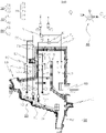
도 1은 본 발명에 따른 FGR 효율성을 향상시킨 연소장치를 도시한 개략도.1 is a schematic view showing a combustion device with improved FGR efficiency according to the present invention.
이하, 첨부된 도면을 이용하여 본 발명의 구성에 대해 보다 구체적으로 살펴보면 다음과 같다.Hereinafter, the configuration of the present invention will be described in more detail with reference to the accompanying drawings.
본 발명은 소각물을 소각시키 위한 것으로 도 1에서와 같이 소각물을 투입하기 위한 투입구(10)가 형성되어 있다. The present invention is to incinerate the incinerated material, as shown in FIG. 1, an
상기 투입구(10)는 도면에서는 상세히 도시되지는 않았지만 구동체에 의해 소각물을 투입시킬 수 있는 구성이 추가될 수 있으며, 소각물 소각시 발생되는 화기가 투입구(10)를 통해 외부로 전달되는 것을 방지하기 위한 수단이 더 포함될 수 있다.Although the
다음으로, 이동부(20)는 투입구(10)를 통해 투입된 소각물을 이동시키기 위한 구성이다.Next, the moving
더욱 구체적으로는 소각물을 소각시키기 위한 연소실(30) 내에서 소각물을 이동시키기 위한 구성이다.More specifically, it is a configuration for moving the incinerated material within the
상기 이동부(20)는 특별히 한정하는 것은 아니지만 소각된 재를 단계적으로 적층시켜 교반이 이루어질 수 있도록 하기 위해 계단형으로 형성될 수 있다.The moving
또한, 상술한 연소실(30)은 이동부(20)에 의해 소각물이 이동이 이루어지는 제1 연소실(31)이 형성되고, 상기 제1 연소실(31)의 상측으로 제2 연소실(32)이 형성되며, 상기 제2 연소실(32)과 격벼(W)에 의해 형성되는 제3 연소실(33)로 이루어질 수 있다.In addition, in the above-described
여기서, 상기 제1 연소실(31)은 소각물을 소각하기 위한 공간이고, 제2 연소실(32)은 제1 연소실(31)에서 소각물이 소각되는 과정에서 발생하는 비산물 및 배기가스를 연소시키기 위해 형성되며, 제3 연소실(33)은 격벽(W)에 의해 제2 연소실(32)과 구획시킴으로써 완전연소가 되지 않은 배기가스가 배출되는 것을 방지하기 할 수 있도록 구성된다.Here, the
다음으로, 연소수단(40)은 연소실(10) 내에 형성되어 소각물을 소각시키기 위해 형성되는 구성으로, 구체적으로는 제1 연소실(31)에 형성되는 제1 버너(41)와 제2 연소실(32)에 형성되는 제2 버너(42)로 이루어진다.Next, the combustion means 40 is formed in the
다음으로, 배출구(50)는 이동부(20)의 끝단부에 형성되는 구성으로, 소각물의 소각처리가 완료되어 생성된 재를 외부로 배출하기 위한 구성으로 상세한 설명은 생략하도록 한다.Next, the
다음으로, 가스 배출구(60)는 연소실(30)을 구성하는 제3 연소실(33)의 일측에 형성되어 연소실(30) 내에서 소각물의 소각시 발생하는 연소가스를 외부로 배출하기 위해 구성된다.Next, the
한편, 본 발명에서는 순환부(70)가 형성되어 있다.On the other hand, in the present invention, the
상기 순환부(70)는 연소실(30)을 구성하는 제3 연소실(33)의 배기가스를 제1 연소실(31)로 공급할 수 있도록 제3 연소실(33)과 제1 연소실(31)을 연결하는 순환관(71)이 형성되고, 상기 순환관(71) 내에는 순환관(71)의 압력 측정을 위한 순환관 압력츨정부(72)와 순환관(71) 내의 온도 측정을 위한 순환관 온도측정부(73) 및 순환관(71)의 단부에 형성되어 제1 연소실(31)로 배기가스를 배출하기 위한 분사용 노즐(74)을 포함하여 이루어질 수 있다.The
특히, 상기 순환관(71)에는 순환관(71)을 개폐할 수 있는 순환관용 댐퍼(75)가 더 포함되어 구성될 수 있다.In particular, the
다음으로, 연소용 송풍기(80)는 상기 순환부(70)를 구성하는 순환관(71)에 연결되어 순환부(70)에서 배기가스와 함께 외부공기를 제1 연소실(31)로 공급할 수 있도록 구성되며, 상기 연소용 송풍기(80)와 순환부(70)의 순환관(71) 사이에는 CGR노즐(N)을 더 포함하여 다량의 공기를 공급할 수 있도록 할 수 있다.Next, the
다음으로, 바이패스부(90)는 상기 순환부(70)의 순환관(71)에서 분기되어 제3 연소실(33)의 배기가스를 제1 연소실(31)로 이동시킬 수 있도록 구성된다.Next, the
구체적으로는, 상기 바이패스부(90)는 순환부(70)의 순환관(71)에 형성되는 CGR노즐(N) 이후의 순환관(71)에서 분기되어 일측이 제1 연소실(31)로 연결되도록 구성되는 바이패스관(91)과 상기 바이패스관(91)과 순환관(71) 사이에 형성되는 바이패스용 댐퍼(92)로 이루어져 있다.Specifically, the
상기와 같은 구성으로 이루어진 본 발명에 따른 FGR 효율성을 향상시킨 연소장치의 작용효과에 대해 살펴보면 다음과 같다.The operational effects of the combustion device with improved FGR efficiency according to the present invention having the configuration as described above are as follows.
우선, 본 발명에 따른 FGR 효율성을 향상시킨 연소장치(100)의 작동은 투입구(10)를 통해 소각물이 투입되면 계단형태로 이루어진 이동부(20)를 통해 소각물이 단계적으로 이동하게 되고, 연소실(30)을 구성하는 제1 연소실(31)에 형성된느 연소수단(40)의 제1 버너(41)에 의해 소각이 이루어지게 된다.First, in the operation of the
상기와 같이 이동부(20)를 통해 이동하는 소각물은 제1 연소실(31)에서 연소되어 배출구(50)를 통해 외부로 배출이 이루어지게 된다.As described above, the incinerated material moving through the moving
한편, 상기 소각물이 제1 버너(41)에 의해 소각이 이루어지게 되면 비산물과 배가가스가 발생하게 되며, 이렇게 발생되는 비산물 및 배기가스는 제1 연소실(31)의 상츠에 형성된 제2 연소실(32)로 이동이 이루어지게 되는데, 이때에, 상기 제2 연소실(32)에는 연소수단(400의 제2 버너(42)가 형성되어 있어, 배기가스 및 비산물을 재차 연소시키게 된다.On the other hand, when the incinerated product is incinerated by the
상기와 같이 제2 연소실(32)에서 연소 후 남은 배기가스 및 비산물은은 제2 제2 연소실(32)과 격벽(W)에 의해 구획된 공간인 제3 연소실(33)로 이동하게 되는데, 이때에 상기 격벽(W)에 의해 구획되는 제2, 3 연소실(32, 33)은 ∩ 형태로 이루어져 배기가스가 이동되도록 되어 있어, 연소실(110)을 구성하는 제1, 2 연소실(31, 32) 내에서 배기가스의 체류시간이 길어지게 되어 완전연소가 될 수 있도록 유도되어 가스 배출구(60)를 통해 배출되는 배기가스에 이산화탄소(CO2)가 거의 남아있지 않도록 하는 효과를 얻을 수 있게 된다.As described above, the exhaust gas and scattered products remaining after combustion in the
한편, 제3 연소실(33)로 유도된 배기가스 및 비산물은 가스 배출구(60)로 바로 배출되는 것이 아니라 순환부(70) 및 연소용 송풍기(80), CGR노즐(N)을 통해 연소실(30)을 구성하는 제1 연소실(31)로 순환시켜 다시 연소가 이루어지도록 함으로써 NOx 및 이산화탄소(CO2)의 생성을 줄일 수 있도록 작용하게 된다.On the other hand, the exhaust gas and scattering products induced to the
즉, 상기 순환부(70)는 연소용 송풍기(80)와 CGR노즐(N)에 의해 외부공기와 더불어 배기가스 및 비산물을 순환관(71))을 통해 제1 연소실(31)로 리사이클링 시킴으로써 제1, 2 연소실(31, 32)에서 소각물의 소각과 더불어 배기가스 및 비산물의 연소작업이 이루어질 수 있으며, 더욱이, 분사용 노즐(74)에 의해 고르게 공급되어 연소반응이 안정적으로 이루어져 최저온도의 상승이 이루어짐으로 인해 연소실(30) 내부의 온도를 하향 평준화를 실현할 수 있고, 이러한 작용으로 인해 저공해 연소가 이루어져 NOx의 생성이 환경규제치의 이하로 줄어드는 효과를 얻을 수 있게 된다.That is, the
한편, 상기 연소실(30)을 구성하는 제3 연소실(33)에는 배기가스 및 비산물이 존재하기 때문에 순환부(70)를 이용한 배기가스 및 비산물의 재순환시 비산물이 순환관(71) 및 분사용 노즐(74)에 쌓임으로써 효율성이 낮아질 수 있게 된다.On the other hand, since exhaust gas and scattering products exist in the
본 발명에서는 순환부(70)를 구성하는 순환관(71) 내부의 압력 및 온도를 측정하기 위한 순환관 압력측정부(72) 및 순환관 온도측정부(73)를 형성하고, 상기 순환관(71) 중 CGR노즐(N) 이후의 순환관(71)에서 분기되는 바이패스관(91) 및 바이패스용 댐퍼(92)로 이루어진 바이패스부(90)를 형성하여 이러한 문제점을 해결하였다.In the present invention, a circulation pipe
즉, 비산물에 의해 상기 순환부(70)의 순환관(71) 또는 분사용 노즐(74)이 막힘이 발생할 경우 이를 순환관(71) 내부의 압력 및 온도를 측정하기 위한 순환관 압력측정부(72) 및 순환관 온도측정부(73)를 통해 모니터링 하여 압력이 높거나 또는 온도가 낮아 사용자가 설정한 설정값을 충족시키지 못할 경우에는 바이패스부(90)를 구성하는 바이패스관(91)을 개방하여 제3 연소실(33)의 배기가스 및 비산물을 순환관(71) 뿐만 아니라, 바이패스관(91)을 통해 제1 연소실(31)로 이동시키도록 하여 배기가스의 순환량을 향상시켜 효율성을 높일 수 있음은 물론, 순환부(70)는 차후에 정비를 통해 정상적으로 작동되도록 함으로써 소각 작업의 중단 없이 작업을 실시할 수 있는 효과를 얻을 수 있게 된다.That is, when the
특히, 본 발명에서는 상술한 순환부(70)와 바이패스부(90)를 다수 형성할 경우 순환량을 향상시켜 더욱 향상된 효과를 얻을 수 있으며, 순환부(70) 중 특히 분사용 노즐(74)이 너무 막혔을 경우 내부 압력이 높아질 수 있을 경우에는 순환부(70)의 순환관용 댐퍼(75)를 이용해 순환관(71)을 통한 순환작업을 멈추고 바이패스부(90)만을 이용해 작업함으로써 소각작업이 안정적이면서 효율적으로 이루어질 수 있는 효과도 얻을 수 있게 된다.In particular, in the present invention, when a plurality of the above-described
상술한 실시 예는 본 발명의 바람직한 일 실시 예에 대해 기재한 것이지만 본 발명은 이에 한정되지 않고 본 발명의 기술적인 사상에서 벗어나지 않는 범위 내에서 다양한 형태로 변경하여 실시할 수 있음을 명시한다.Although the above-described embodiment has been described with respect to a preferred embodiment of the present invention, the present invention is not limited thereto, and it is indicated that it can be changed and implemented in various forms without departing from the technical spirit of the present invention.
10 : 투입구
20 : 이동부
30 : 연소실
31 : 제1 연소실 32 : 제2 연소실 33 : 제3 연소실
40 : 연소수단
41 : 제1 버너 42 : 제2 버너
50 : 배출구
60 : 가스 배출구
70 : 순환부
71 : 순환관 72 : 순환관 압력측정부 73 : 순환관 온도측정부
74 : 분사용 노즐 75: 순환관용 댐퍼
80 : 연소용 송풍기
N : CGR노즐
90 : 바이패스부
91 : 바이패스관 92 : 바이패스용 댐퍼
100 : FGR 효율성을 향상시킨 연소장치10: inlet
20: moving part
30: combustion chamber
31: 1st combustion chamber 32: 2nd combustion chamber 33: 3rd combustion chamber
40: combustion means
41: first burner 42: second burner
50: outlet
60: gas outlet
70: circulation part
71: circulation pipe 72: circulation pipe pressure measuring unit 73: circulation pipe temperature measuring unit
74: nozzle for injection 75: damper for circulation pipe
80: blower for combustion
N : CGR nozzle
90: bypass unit
91: bypass pipe 92: damper for bypass
100: Combustion device with improved FGR efficiency
Claims (3)
상기 투입구를 통해 투입된 소각물이 이동하는 이동부;
상기 투입구를 통해 투입된 소각물을 1차 연소하기 위한 1차 연소실의 상측에 형성되는 제2 연소실과 상기 제2 연소실과 격벽에 의해 구획되는 제3 연소실로 이루어진 연소실;
상기 제1 연소실 내에 설치되는 제1 버너와 제2 연소실 내에 형성되는 제2 버너로 이루어진 연소수단;
상기 연소실에서 이동하여 소각된 재를 외부로 배출하기 위한 배출구;
상기 연소실의 제2 연소실의 일측에 형성되어 가스를 배출하기 위한 가스 배출구;
상기 연소실을 구성하는 제3 연소실의 배기가스를 제1 연소실로 순환시키기 위한 순환관과 상기 제1 연소실로 배기가스를 공급하기 위해 순환관의 단부에 형성되는 분사용 노즐과 순환관 내의 압력을 측정하기 위한 순환관 압력측정부와 상기 순환관의 온도를 측정하기 위한 순환관 온도측정부로 이루어진 순환부;
상기 순환부의 순환관에 연결되는 연소용 송풍기;
상기 순환부의 순환관과 연소용 송풍기 사이에 형성되는 CGR노즐;
상기 순환부의 순환관에서 분기되어 제3 연소실의 배기가스를 제1 연소실로 순환시키기 위한 바이패스관과 상기 바이패스관 내에 설치되며 순환부의 순환관 압력측정부와 순환관 온도측정부를 통해 순환관 내의 온도가 설정값보다 낮거나 또는 순환관 내의 압력이 설정값보다 높을 경우 자동 개방되도록 작동하는 바이패스용댐퍼로 이루어진 바이패스부;를 포함하여 이루어진 것에 특징이 있는 FGR 효율성을 향상시킨 연소장치.
Incineration is inputted;
a moving unit for moving the incinerated material input through the inlet;
a combustion chamber consisting of a second combustion chamber formed above the primary combustion chamber for primary combustion of the incinerated material input through the inlet, and a third combustion chamber partitioned by the second combustion chamber and a partition;
a combustion means comprising a first burner installed in the first combustion chamber and a second burner formed in the second combustion chamber;
an outlet for discharging the incinerated ash to the outside by moving in the combustion chamber;
a gas outlet formed on one side of the second combustion chamber of the combustion chamber to discharge gas;
A circulation pipe for circulating the exhaust gas of the third combustion chamber constituting the combustion chamber to the first combustion chamber, and a nozzle for injection formed at the end of the circulation pipe for supplying the exhaust gas to the first combustion chamber, and the pressure in the circulation pipe a circulation unit comprising a circulation pipe pressure measuring unit and a circulation pipe temperature measuring unit for measuring the temperature of the circulation pipe;
a combustion blower connected to the circulation pipe of the circulation unit;
a CGR nozzle formed between the circulation pipe of the circulation part and the blower for combustion;
A bypass pipe for circulating the exhaust gas of the third combustion chamber to the first combustion chamber branched from the circulation pipe of the circulation part and is installed in the bypass pipe, and is provided in the circulation pipe through the circulation pipe pressure measuring part and the circulation pipe temperature measuring part of the circulation part. A combustion device with improved FGR efficiency, characterized in that it includes; a bypass unit comprising a bypass damper that operates to automatically open when the temperature is lower than the set value or the pressure in the circulation pipe is higher than the set value.
[Claim 2] The combustion device with improved FGR efficiency according to claim 1, wherein the circulation pipe of the circulation part further includes a damper for a circulation pipe capable of opening and closing the circulation pipe.
Priority Applications (1)
| Application Number | Priority Date | Filing Date | Title |
|---|---|---|---|
| KR1020210046246A KR102516434B1 (en) | 2021-04-09 | 2021-04-09 | Combustion Device Improves FGR Efficiency |
Applications Claiming Priority (1)
| Application Number | Priority Date | Filing Date | Title |
|---|---|---|---|
| KR1020210046246A KR102516434B1 (en) | 2021-04-09 | 2021-04-09 | Combustion Device Improves FGR Efficiency |
Publications (2)
| Publication Number | Publication Date |
|---|---|
| KR20220140131A true KR20220140131A (en) | 2022-10-18 |
| KR102516434B1 KR102516434B1 (en) | 2023-04-03 |
Family
ID=83803708
Family Applications (1)
| Application Number | Title | Priority Date | Filing Date |
|---|---|---|---|
| KR1020210046246A KR102516434B1 (en) | 2021-04-09 | 2021-04-09 | Combustion Device Improves FGR Efficiency |
Country Status (1)
| Country | Link |
|---|---|
| KR (1) | KR102516434B1 (en) |
Citations (3)
| Publication number | Priority date | Publication date | Assignee | Title |
|---|---|---|---|---|
| JP2004239509A (en) * | 2003-02-05 | 2004-08-26 | Jfe Engineering Kk | Combustion control method of refuse incinerator, and refuse incinerator |
| JP2008096045A (en) * | 2006-10-13 | 2008-04-24 | Mitsubishi Heavy Ind Ltd | Combustion controller for stoker type incinerator |
| JP2010223474A (en) * | 2009-03-23 | 2010-10-07 | Mitsubishi Heavy Industries Environment & Chemical Engineering Co Ltd | Stoker type incinerator and its operation method |
-
2021
- 2021-04-09 KR KR1020210046246A patent/KR102516434B1/en active IP Right Grant
Patent Citations (3)
| Publication number | Priority date | Publication date | Assignee | Title |
|---|---|---|---|---|
| JP2004239509A (en) * | 2003-02-05 | 2004-08-26 | Jfe Engineering Kk | Combustion control method of refuse incinerator, and refuse incinerator |
| JP2008096045A (en) * | 2006-10-13 | 2008-04-24 | Mitsubishi Heavy Ind Ltd | Combustion controller for stoker type incinerator |
| JP2010223474A (en) * | 2009-03-23 | 2010-10-07 | Mitsubishi Heavy Industries Environment & Chemical Engineering Co Ltd | Stoker type incinerator and its operation method |
Also Published As
| Publication number | Publication date |
|---|---|
| KR102516434B1 (en) | 2023-04-03 |
Similar Documents
| Publication | Publication Date | Title |
|---|---|---|
| JP4479655B2 (en) | Grate-type waste incinerator and its combustion control method | |
| TWI551824B (en) | Combustion control method for burner apparatus | |
| KR101406567B1 (en) | Method for reducing NOx by flue gas recirculation | |
| US8403662B2 (en) | Reactor employing high-temperature air combustion technology | |
| KR102524977B1 (en) | Method and apparatus for controlling NOx in incinerator by suppressing combustion variability | |
| KR101528807B1 (en) | Super-low NOx eission combustion apparatus using coanda effect | |
| KR101061765B1 (en) | Flameless regenerative thermal oxidizer having gas mixing devices | |
| KR100676868B1 (en) | COMBUSTION SYSTEM USING A BURNER GENERATING AN ULTRA LOW NOx EMISSIONS | |
| KR20220140131A (en) | Combustion Device Improves FGR Efficiency | |
| JP6887917B2 (en) | Incinerator plant | |
| CN105209825B (en) | Using high temperature FGR and the super low NOx combustion apparatus of Coanda effect | |
| JP2007107849A (en) | Boiler equipment, operation method for it, and improvement method for it | |
| JP5501198B2 (en) | Low NOx / low dust combustion method and boiler combustion chamber | |
| JP3462394B2 (en) | Combustion control method of regenerative burner device and burner device | |
| KR101289411B1 (en) | Low pollutant emission combustion using high-temperature fgr and nozzle of coanda effect | |
| KR100583818B1 (en) | Self regenerative single head burner | |
| JPH03125808A (en) | Fluidized-bed type refuse incinerator | |
| JP2005265410A (en) | Waste incinerator | |
| KR101453859B1 (en) | Super-low NOx Emission Combustion Apparatus Using Coanda Effect | |
| JP2004077013A (en) | Operation method of waste incinerator, and waste incinerator | |
| RU2799700C1 (en) | Device, burner and method for firing ceramic products | |
| JP2001141207A (en) | Combustor and method for combustion | |
| KR102146185B1 (en) | Stoker type incinerator | |
| EP1500875A1 (en) | Method of operating waste incinerator and waste incinerator | |
| KR20010065375A (en) | Three step combustion type burner of an oxide rare combustion type |
Legal Events
| Date | Code | Title | Description |
|---|---|---|---|
| E902 | Notification of reason for refusal | ||
| E701 | Decision to grant or registration of patent right | ||
| GRNT | Written decision to grant |