KR20220133190A - Cathode active material, secondary battery, electronic device - Google Patents
Cathode active material, secondary battery, electronic device Download PDFInfo
- Publication number
- KR20220133190A KR20220133190A KR1020227024372A KR20227024372A KR20220133190A KR 20220133190 A KR20220133190 A KR 20220133190A KR 1020227024372 A KR1020227024372 A KR 1020227024372A KR 20227024372 A KR20227024372 A KR 20227024372A KR 20220133190 A KR20220133190 A KR 20220133190A
- Authority
- KR
- South Korea
- Prior art keywords
- active material
- positive electrode
- secondary battery
- electrode active
- lithium
- Prior art date
Links
- 239000006182 cathode active material Substances 0.000 title abstract description 10
- 239000007774 positive electrode material Substances 0.000 claims abstract description 309
- 150000003624 transition metals Chemical class 0.000 claims abstract description 71
- 229910052723 transition metal Inorganic materials 0.000 claims abstract description 70
- 229910052744 lithium Inorganic materials 0.000 claims description 151
- WHXSMMKQMYFTQS-UHFFFAOYSA-N Lithium Chemical compound [Li] WHXSMMKQMYFTQS-UHFFFAOYSA-N 0.000 claims description 140
- PXHVJJICTQNCMI-UHFFFAOYSA-N Nickel Chemical compound [Ni] PXHVJJICTQNCMI-UHFFFAOYSA-N 0.000 claims description 120
- 239000011777 magnesium Substances 0.000 claims description 88
- 229910052749 magnesium Inorganic materials 0.000 claims description 83
- FYYHWMGAXLPEAU-UHFFFAOYSA-N Magnesium Chemical compound [Mg] FYYHWMGAXLPEAU-UHFFFAOYSA-N 0.000 claims description 82
- 229910052759 nickel Inorganic materials 0.000 claims description 60
- 229910052782 aluminium Inorganic materials 0.000 claims description 50
- XAGFODPZIPBFFR-UHFFFAOYSA-N aluminium Chemical compound [Al] XAGFODPZIPBFFR-UHFFFAOYSA-N 0.000 claims description 49
- 229910052731 fluorine Inorganic materials 0.000 claims description 43
- 239000011737 fluorine Substances 0.000 claims description 42
- 238000000034 method Methods 0.000 claims description 36
- 229910052736 halogen Inorganic materials 0.000 claims description 20
- 150000002367 halogens Chemical class 0.000 claims description 19
- PXGOKWXKJXAPGV-UHFFFAOYSA-N Fluorine Chemical compound FF PXGOKWXKJXAPGV-UHFFFAOYSA-N 0.000 claims 1
- 238000007600 charging Methods 0.000 abstract description 95
- 238000007599 discharging Methods 0.000 abstract description 44
- 238000010191 image analysis Methods 0.000 abstract description 6
- 238000001000 micrograph Methods 0.000 abstract description 5
- 238000010828 elution Methods 0.000 abstract description 3
- 238000007086 side reaction Methods 0.000 abstract description 3
- 239000013078 crystal Substances 0.000 description 206
- 239000000463 material Substances 0.000 description 103
- 239000010410 layer Substances 0.000 description 96
- 239000002245 particle Substances 0.000 description 81
- GUTLYIVDDKVIGB-UHFFFAOYSA-N cobalt atom Chemical group [Co] GUTLYIVDDKVIGB-UHFFFAOYSA-N 0.000 description 78
- 229910017052 cobalt Inorganic materials 0.000 description 75
- 239000010941 cobalt Substances 0.000 description 75
- PQXKHYXIUOZZFA-UHFFFAOYSA-M lithium fluoride Chemical compound [Li+].[F-] PQXKHYXIUOZZFA-UHFFFAOYSA-M 0.000 description 74
- -1 graphene compound Chemical class 0.000 description 63
- 239000002344 surface layer Substances 0.000 description 60
- 239000000203 mixture Substances 0.000 description 55
- OKTJSMMVPCPJKN-UHFFFAOYSA-N Carbon Chemical compound [C] OKTJSMMVPCPJKN-UHFFFAOYSA-N 0.000 description 50
- 239000000654 additive Substances 0.000 description 49
- 229910021389 graphene Inorganic materials 0.000 description 47
- 239000002131 composite material Substances 0.000 description 45
- 235000002639 sodium chloride Nutrition 0.000 description 41
- QVGXLLKOCUKJST-UHFFFAOYSA-N atomic oxygen Chemical compound [O] QVGXLLKOCUKJST-UHFFFAOYSA-N 0.000 description 40
- 229910052760 oxygen Inorganic materials 0.000 description 40
- 239000001301 oxygen Substances 0.000 description 40
- 239000000523 sample Substances 0.000 description 40
- YCKRFDGAMUMZLT-UHFFFAOYSA-N Fluorine atom Chemical compound [F] YCKRFDGAMUMZLT-UHFFFAOYSA-N 0.000 description 39
- 230000006870 function Effects 0.000 description 38
- FAPWRFPIFSIZLT-UHFFFAOYSA-M Sodium chloride Chemical compound [Na+].[Cl-] FAPWRFPIFSIZLT-UHFFFAOYSA-M 0.000 description 37
- 239000011780 sodium chloride Substances 0.000 description 35
- 238000004519 manufacturing process Methods 0.000 description 32
- 125000004429 atom Chemical group 0.000 description 29
- 238000010438 heat treatment Methods 0.000 description 29
- 229910052751 metal Inorganic materials 0.000 description 29
- 239000002184 metal Substances 0.000 description 29
- 239000007784 solid electrolyte Substances 0.000 description 29
- 230000000996 additive effect Effects 0.000 description 28
- 238000002441 X-ray diffraction Methods 0.000 description 27
- 238000004458 analytical method Methods 0.000 description 27
- 238000000137 annealing Methods 0.000 description 26
- 238000002156 mixing Methods 0.000 description 26
- 239000011149 active material Substances 0.000 description 25
- 239000008151 electrolyte solution Substances 0.000 description 25
- 239000010408 film Substances 0.000 description 25
- 239000011572 manganese Substances 0.000 description 23
- PWHULOQIROXLJO-UHFFFAOYSA-N Manganese Chemical compound [Mn] PWHULOQIROXLJO-UHFFFAOYSA-N 0.000 description 22
- 229910052748 manganese Inorganic materials 0.000 description 22
- 239000007773 negative electrode material Substances 0.000 description 22
- 230000000694 effects Effects 0.000 description 21
- 239000003792 electrolyte Substances 0.000 description 21
- 230000004907 flux Effects 0.000 description 21
- 238000010586 diagram Methods 0.000 description 20
- HBBGRARXTFLTSG-UHFFFAOYSA-N Lithium ion Chemical compound [Li+] HBBGRARXTFLTSG-UHFFFAOYSA-N 0.000 description 19
- 229910001416 lithium ion Inorganic materials 0.000 description 19
- 230000002829 reductive effect Effects 0.000 description 19
- 229910018871 CoO 2 Inorganic materials 0.000 description 18
- 230000008859 change Effects 0.000 description 18
- 239000004020 conductor Substances 0.000 description 18
- XEEYBQQBJWHFJM-UHFFFAOYSA-N Iron Chemical compound [Fe] XEEYBQQBJWHFJM-UHFFFAOYSA-N 0.000 description 17
- 229910012851 LiCoO 2 Inorganic materials 0.000 description 17
- 229910052698 phosphorus Inorganic materials 0.000 description 17
- 238000003860 storage Methods 0.000 description 17
- OAICVXFJPJFONN-UHFFFAOYSA-N Phosphorus Chemical compound [P] OAICVXFJPJFONN-UHFFFAOYSA-N 0.000 description 16
- 239000011574 phosphorus Substances 0.000 description 16
- 230000006641 stabilisation Effects 0.000 description 16
- 238000011105 stabilization Methods 0.000 description 16
- 229910015118 LiMO Inorganic materials 0.000 description 15
- 238000004833 X-ray photoelectron spectroscopy Methods 0.000 description 15
- 102100027368 Histone H1.3 Human genes 0.000 description 14
- 101001009450 Homo sapiens Histone H1.3 Proteins 0.000 description 14
- 150000001450 anions Chemical class 0.000 description 14
- 239000003990 capacitor Substances 0.000 description 14
- 150000001875 compounds Chemical class 0.000 description 14
- 238000002844 melting Methods 0.000 description 14
- 230000008018 melting Effects 0.000 description 14
- 239000010936 titanium Substances 0.000 description 14
- KRHYYFGTRYWZRS-UHFFFAOYSA-N Fluorane Chemical compound F KRHYYFGTRYWZRS-UHFFFAOYSA-N 0.000 description 13
- 239000011230 binding agent Substances 0.000 description 13
- 238000004453 electron probe microanalysis Methods 0.000 description 13
- ORUIBWPALBXDOA-UHFFFAOYSA-L magnesium fluoride Chemical compound [F-].[F-].[Mg+2] ORUIBWPALBXDOA-UHFFFAOYSA-L 0.000 description 13
- 229910001635 magnesium fluoride Inorganic materials 0.000 description 13
- RTAQQCXQSZGOHL-UHFFFAOYSA-N Titanium Chemical compound [Ti] RTAQQCXQSZGOHL-UHFFFAOYSA-N 0.000 description 12
- 239000012298 atmosphere Substances 0.000 description 12
- 229910052799 carbon Inorganic materials 0.000 description 12
- 238000006243 chemical reaction Methods 0.000 description 12
- 238000009826 distribution Methods 0.000 description 12
- WPBNNNQJVZRUHP-UHFFFAOYSA-L manganese(2+);methyl n-[[2-(methoxycarbonylcarbamothioylamino)phenyl]carbamothioyl]carbamate;n-[2-(sulfidocarbothioylamino)ethyl]carbamodithioate Chemical group [Mn+2].[S-]C(=S)NCCNC([S-])=S.COC(=O)NC(=S)NC1=CC=CC=C1NC(=S)NC(=O)OC WPBNNNQJVZRUHP-UHFFFAOYSA-L 0.000 description 12
- LIVNPJMFVYWSIS-UHFFFAOYSA-N silicon monoxide Chemical compound [Si-]#[O+] LIVNPJMFVYWSIS-UHFFFAOYSA-N 0.000 description 12
- XUIMIQQOPSSXEZ-UHFFFAOYSA-N Silicon Chemical compound [Si] XUIMIQQOPSSXEZ-UHFFFAOYSA-N 0.000 description 11
- 239000000460 chlorine Substances 0.000 description 11
- 239000011651 chromium Substances 0.000 description 11
- 230000000052 comparative effect Effects 0.000 description 11
- 229910002804 graphite Inorganic materials 0.000 description 11
- 239000010439 graphite Substances 0.000 description 11
- 238000001095 inductively coupled plasma mass spectrometry Methods 0.000 description 11
- 238000005259 measurement Methods 0.000 description 11
- 229910052710 silicon Inorganic materials 0.000 description 11
- 239000010703 silicon Substances 0.000 description 11
- 229910052719 titanium Inorganic materials 0.000 description 11
- 150000001768 cations Chemical class 0.000 description 10
- 238000004891 communication Methods 0.000 description 10
- 238000000354 decomposition reaction Methods 0.000 description 10
- 238000002149 energy-dispersive X-ray emission spectroscopy Methods 0.000 description 10
- 230000008569 process Effects 0.000 description 10
- 229920005989 resin Polymers 0.000 description 10
- 239000011347 resin Substances 0.000 description 10
- 238000001878 scanning electron micrograph Methods 0.000 description 10
- 239000002904 solvent Substances 0.000 description 10
- 239000003795 chemical substances by application Substances 0.000 description 9
- 230000007797 corrosion Effects 0.000 description 9
- 238000005260 corrosion Methods 0.000 description 9
- 230000007423 decrease Effects 0.000 description 9
- 238000011156 evaluation Methods 0.000 description 9
- 230000014759 maintenance of location Effects 0.000 description 9
- VYZAMTAEIAYCRO-UHFFFAOYSA-N Chromium Chemical compound [Cr] VYZAMTAEIAYCRO-UHFFFAOYSA-N 0.000 description 8
- OIFBSDVPJOWBCH-UHFFFAOYSA-N Diethyl carbonate Chemical compound CCOC(=O)OCC OIFBSDVPJOWBCH-UHFFFAOYSA-N 0.000 description 8
- KMTRUDSVKNLOMY-UHFFFAOYSA-N Ethylene carbonate Chemical compound O=C1OCCO1 KMTRUDSVKNLOMY-UHFFFAOYSA-N 0.000 description 8
- 239000004743 Polypropylene Substances 0.000 description 8
- 238000004364 calculation method Methods 0.000 description 8
- 229910052804 chromium Inorganic materials 0.000 description 8
- CKFRRHLHAJZIIN-UHFFFAOYSA-N cobalt lithium Chemical compound [Li].[Co] CKFRRHLHAJZIIN-UHFFFAOYSA-N 0.000 description 8
- 229910052742 iron Inorganic materials 0.000 description 8
- 229920000642 polymer Polymers 0.000 description 8
- 229920001155 polypropylene Polymers 0.000 description 8
- 239000004065 semiconductor Substances 0.000 description 8
- WMFOQBRAJBCJND-UHFFFAOYSA-M Lithium hydroxide Chemical compound [Li+].[OH-] WMFOQBRAJBCJND-UHFFFAOYSA-M 0.000 description 7
- 239000002033 PVDF binder Substances 0.000 description 7
- 239000010949 copper Substances 0.000 description 7
- 230000007547 defect Effects 0.000 description 7
- 239000012535 impurity Substances 0.000 description 7
- TWNQGVIAIRXVLR-UHFFFAOYSA-N oxo(oxoalumanyloxy)alumane Chemical compound O=[Al]O[Al]=O TWNQGVIAIRXVLR-UHFFFAOYSA-N 0.000 description 7
- 229920002647 polyamide Polymers 0.000 description 7
- 229920002981 polyvinylidene fluoride Polymers 0.000 description 7
- 238000006722 reduction reaction Methods 0.000 description 7
- 239000000126 substance Substances 0.000 description 7
- 229910052717 sulfur Inorganic materials 0.000 description 7
- WEVYAHXRMPXWCK-UHFFFAOYSA-N Acetonitrile Chemical compound CC#N WEVYAHXRMPXWCK-UHFFFAOYSA-N 0.000 description 6
- RTZKZFJDLAIYFH-UHFFFAOYSA-N Diethyl ether Chemical compound CCOCC RTZKZFJDLAIYFH-UHFFFAOYSA-N 0.000 description 6
- SECXISVLQFMRJM-UHFFFAOYSA-N N-Methylpyrrolidone Chemical compound CN1CCCC1=O SECXISVLQFMRJM-UHFFFAOYSA-N 0.000 description 6
- HEMHJVSKTPXQMS-UHFFFAOYSA-M Sodium hydroxide Chemical compound [OH-].[Na+] HEMHJVSKTPXQMS-UHFFFAOYSA-M 0.000 description 6
- NINIDFKCEFEMDL-UHFFFAOYSA-N Sulfur Chemical compound [S] NINIDFKCEFEMDL-UHFFFAOYSA-N 0.000 description 6
- MCMNRKCIXSYSNV-UHFFFAOYSA-N Zirconium dioxide Chemical compound O=[Zr]=O MCMNRKCIXSYSNV-UHFFFAOYSA-N 0.000 description 6
- 229910045601 alloy Inorganic materials 0.000 description 6
- 239000000956 alloy Substances 0.000 description 6
- 229920003235 aromatic polyamide Polymers 0.000 description 6
- 235000013339 cereals Nutrition 0.000 description 6
- 238000003780 insertion Methods 0.000 description 6
- 230000037431 insertion Effects 0.000 description 6
- CPLXHLVBOLITMK-UHFFFAOYSA-N magnesium oxide Inorganic materials [Mg]=O CPLXHLVBOLITMK-UHFFFAOYSA-N 0.000 description 6
- 150000002739 metals Chemical class 0.000 description 6
- 229910000480 nickel oxide Inorganic materials 0.000 description 6
- 238000010298 pulverizing process Methods 0.000 description 6
- 239000002994 raw material Substances 0.000 description 6
- 229910052596 spinel Inorganic materials 0.000 description 6
- 239000011029 spinel Substances 0.000 description 6
- 229910001220 stainless steel Inorganic materials 0.000 description 6
- 239000010935 stainless steel Substances 0.000 description 6
- 239000011593 sulfur Substances 0.000 description 6
- 238000005211 surface analysis Methods 0.000 description 6
- 229910052720 vanadium Inorganic materials 0.000 description 6
- GPPXJZIENCGNKB-UHFFFAOYSA-N vanadium Chemical compound [V]#[V] GPPXJZIENCGNKB-UHFFFAOYSA-N 0.000 description 6
- 239000011701 zinc Substances 0.000 description 6
- VAYTZRYEBVHVLE-UHFFFAOYSA-N 1,3-dioxol-2-one Chemical compound O=C1OC=CO1 VAYTZRYEBVHVLE-UHFFFAOYSA-N 0.000 description 5
- ZAMOUSCENKQFHK-UHFFFAOYSA-N Chlorine atom Chemical compound [Cl] ZAMOUSCENKQFHK-UHFFFAOYSA-N 0.000 description 5
- 229920003171 Poly (ethylene oxide) Polymers 0.000 description 5
- VYPSYNLAJGMNEJ-UHFFFAOYSA-N Silicium dioxide Chemical compound O=[Si]=O VYPSYNLAJGMNEJ-UHFFFAOYSA-N 0.000 description 5
- UCKMPCXJQFINFW-UHFFFAOYSA-N Sulphide Chemical compound [S-2] UCKMPCXJQFINFW-UHFFFAOYSA-N 0.000 description 5
- 238000003917 TEM image Methods 0.000 description 5
- HCHKCACWOHOZIP-UHFFFAOYSA-N Zinc Chemical compound [Zn] HCHKCACWOHOZIP-UHFFFAOYSA-N 0.000 description 5
- KLARSDUHONHPRF-UHFFFAOYSA-N [Li].[Mn] Chemical compound [Li].[Mn] KLARSDUHONHPRF-UHFFFAOYSA-N 0.000 description 5
- 230000002411 adverse Effects 0.000 description 5
- 239000004760 aramid Substances 0.000 description 5
- 229910021383 artificial graphite Inorganic materials 0.000 description 5
- 230000005540 biological transmission Effects 0.000 description 5
- 229910052801 chlorine Inorganic materials 0.000 description 5
- 229910052802 copper Inorganic materials 0.000 description 5
- 238000000605 extraction Methods 0.000 description 5
- 238000011049 filling Methods 0.000 description 5
- 238000001036 glow-discharge mass spectrometry Methods 0.000 description 5
- 150000004820 halides Chemical class 0.000 description 5
- 239000010442 halite Substances 0.000 description 5
- 229910000040 hydrogen fluoride Inorganic materials 0.000 description 5
- UQSXHKLRYXJYBZ-UHFFFAOYSA-N iron oxide Inorganic materials [Fe]=O UQSXHKLRYXJYBZ-UHFFFAOYSA-N 0.000 description 5
- 230000007246 mechanism Effects 0.000 description 5
- 239000007769 metal material Substances 0.000 description 5
- VNWKTOKETHGBQD-UHFFFAOYSA-N methane Chemical compound C VNWKTOKETHGBQD-UHFFFAOYSA-N 0.000 description 5
- 230000009467 reduction Effects 0.000 description 5
- 239000002002 slurry Substances 0.000 description 5
- 239000010409 thin film Substances 0.000 description 5
- 238000004804 winding Methods 0.000 description 5
- 229910052725 zinc Inorganic materials 0.000 description 5
- HEZMWWAKWCSUCB-PHDIDXHHSA-N (3R,4R)-3,4-dihydroxycyclohexa-1,5-diene-1-carboxylic acid Chemical compound O[C@@H]1C=CC(C(O)=O)=C[C@H]1O HEZMWWAKWCSUCB-PHDIDXHHSA-N 0.000 description 4
- CSCPPACGZOOCGX-UHFFFAOYSA-N Acetone Chemical compound CC(C)=O CSCPPACGZOOCGX-UHFFFAOYSA-N 0.000 description 4
- IJGRMHOSHXDMSA-UHFFFAOYSA-N Atomic nitrogen Chemical compound N#N IJGRMHOSHXDMSA-UHFFFAOYSA-N 0.000 description 4
- RYGMFSIKBFXOCR-UHFFFAOYSA-N Copper Chemical compound [Cu] RYGMFSIKBFXOCR-UHFFFAOYSA-N 0.000 description 4
- 229910013290 LiNiO 2 Inorganic materials 0.000 description 4
- SOXUFMZTHZXOGC-UHFFFAOYSA-N [Li].[Mn].[Co].[Ni] Chemical group [Li].[Mn].[Co].[Ni] SOXUFMZTHZXOGC-UHFFFAOYSA-N 0.000 description 4
- 239000006183 anode active material Substances 0.000 description 4
- 239000012300 argon atmosphere Substances 0.000 description 4
- 229910052785 arsenic Inorganic materials 0.000 description 4
- 230000008901 benefit Effects 0.000 description 4
- 229910000428 cobalt oxide Inorganic materials 0.000 description 4
- IVMYJDGYRUAWML-UHFFFAOYSA-N cobalt(ii) oxide Chemical compound [Co]=O IVMYJDGYRUAWML-UHFFFAOYSA-N 0.000 description 4
- 230000005684 electric field Effects 0.000 description 4
- 238000000921 elemental analysis Methods 0.000 description 4
- AMWRITDGCCNYAT-UHFFFAOYSA-L hydroxy(oxo)manganese;manganese Chemical compound [Mn].O[Mn]=O.O[Mn]=O AMWRITDGCCNYAT-UHFFFAOYSA-L 0.000 description 4
- 238000009434 installation Methods 0.000 description 4
- 150000002500 ions Chemical class 0.000 description 4
- AMXOYNBUYSYVKV-UHFFFAOYSA-M lithium bromide Chemical compound [Li+].[Br-] AMXOYNBUYSYVKV-UHFFFAOYSA-M 0.000 description 4
- 239000000395 magnesium oxide Substances 0.000 description 4
- 239000002931 mesocarbon microbead Substances 0.000 description 4
- 150000004767 nitrides Chemical class 0.000 description 4
- GNRSAWUEBMWBQH-UHFFFAOYSA-N oxonickel Chemical compound [Ni]=O GNRSAWUEBMWBQH-UHFFFAOYSA-N 0.000 description 4
- 239000000843 powder Substances 0.000 description 4
- 238000003825 pressing Methods 0.000 description 4
- 238000012545 processing Methods 0.000 description 4
- 239000011734 sodium Substances 0.000 description 4
- YTZKOQUCBOVLHL-UHFFFAOYSA-N tert-butylbenzene Chemical compound CC(C)(C)C1=CC=CC=C1 YTZKOQUCBOVLHL-UHFFFAOYSA-N 0.000 description 4
- 210000000707 wrist Anatomy 0.000 description 4
- ZOXJGFHDIHLPTG-UHFFFAOYSA-N Boron Chemical compound [B] ZOXJGFHDIHLPTG-UHFFFAOYSA-N 0.000 description 3
- OYPRJOBELJOOCE-UHFFFAOYSA-N Calcium Chemical compound [Ca] OYPRJOBELJOOCE-UHFFFAOYSA-N 0.000 description 3
- XEKOWRVHYACXOJ-UHFFFAOYSA-N Ethyl acetate Chemical compound CCOC(C)=O XEKOWRVHYACXOJ-UHFFFAOYSA-N 0.000 description 3
- 229910013870 LiPF 6 Inorganic materials 0.000 description 3
- 239000004952 Polyamide Substances 0.000 description 3
- 239000004698 Polyethylene Substances 0.000 description 3
- 230000001133 acceleration Effects 0.000 description 3
- WNROFYMDJYEPJX-UHFFFAOYSA-K aluminium hydroxide Chemical compound [OH-].[OH-].[OH-].[Al+3] WNROFYMDJYEPJX-UHFFFAOYSA-K 0.000 description 3
- RQNWIZPPADIBDY-UHFFFAOYSA-N arsenic atom Chemical compound [As] RQNWIZPPADIBDY-UHFFFAOYSA-N 0.000 description 3
- 239000011324 bead Substances 0.000 description 3
- JFDZBHWFFUWGJE-UHFFFAOYSA-N benzonitrile Chemical compound N#CC1=CC=CC=C1 JFDZBHWFFUWGJE-UHFFFAOYSA-N 0.000 description 3
- 229910052796 boron Inorganic materials 0.000 description 3
- 229910052791 calcium Inorganic materials 0.000 description 3
- 239000011575 calcium Substances 0.000 description 3
- 239000003054 catalyst Substances 0.000 description 3
- 239000000919 ceramic Substances 0.000 description 3
- 229910010293 ceramic material Inorganic materials 0.000 description 3
- 239000011248 coating agent Substances 0.000 description 3
- 238000000576 coating method Methods 0.000 description 3
- 238000010277 constant-current charging Methods 0.000 description 3
- 230000006866 deterioration Effects 0.000 description 3
- 238000011161 development Methods 0.000 description 3
- 230000018109 developmental process Effects 0.000 description 3
- 238000009792 diffusion process Methods 0.000 description 3
- 239000000428 dust Substances 0.000 description 3
- 230000005611 electricity Effects 0.000 description 3
- 238000002003 electron diffraction Methods 0.000 description 3
- 239000003571 electronic cigarette Substances 0.000 description 3
- 229910052732 germanium Inorganic materials 0.000 description 3
- 238000000227 grinding Methods 0.000 description 3
- 125000002887 hydroxy group Chemical group [H]O* 0.000 description 3
- 230000006872 improvement Effects 0.000 description 3
- 239000011810 insulating material Substances 0.000 description 3
- 239000007788 liquid Substances 0.000 description 3
- XGZVUEUWXADBQD-UHFFFAOYSA-L lithium carbonate Chemical compound [Li+].[Li+].[O-]C([O-])=O XGZVUEUWXADBQD-UHFFFAOYSA-L 0.000 description 3
- KWGKDLIKAYFUFQ-UHFFFAOYSA-M lithium chloride Chemical compound [Li+].[Cl-] KWGKDLIKAYFUFQ-UHFFFAOYSA-M 0.000 description 3
- 229910021382 natural graphite Inorganic materials 0.000 description 3
- 229910052758 niobium Inorganic materials 0.000 description 3
- 239000010955 niobium Substances 0.000 description 3
- GUCVJGMIXFAOAE-UHFFFAOYSA-N niobium atom Chemical compound [Nb] GUCVJGMIXFAOAE-UHFFFAOYSA-N 0.000 description 3
- 229910052757 nitrogen Inorganic materials 0.000 description 3
- 238000007254 oxidation reaction Methods 0.000 description 3
- 239000000123 paper Substances 0.000 description 3
- 229920000573 polyethylene Polymers 0.000 description 3
- 230000002787 reinforcement Effects 0.000 description 3
- 229910052814 silicon oxide Inorganic materials 0.000 description 3
- 238000006467 substitution reaction Methods 0.000 description 3
- 230000001629 suppression Effects 0.000 description 3
- FSSPGSAQUIYDCN-UHFFFAOYSA-N 1,3-Propane sultone Chemical compound O=S1(=O)CCCO1 FSSPGSAQUIYDCN-UHFFFAOYSA-N 0.000 description 2
- RYHBNJHYFVUHQT-UHFFFAOYSA-N 1,4-Dioxane Chemical compound C1COCCO1 RYHBNJHYFVUHQT-UHFFFAOYSA-N 0.000 description 2
- YEJRWHAVMIAJKC-UHFFFAOYSA-N 4-Butyrolactone Chemical compound O=C1CCCO1 YEJRWHAVMIAJKC-UHFFFAOYSA-N 0.000 description 2
- SBLRHMKNNHXPHG-UHFFFAOYSA-N 4-fluoro-1,3-dioxolan-2-one Chemical compound FC1COC(=O)O1 SBLRHMKNNHXPHG-UHFFFAOYSA-N 0.000 description 2
- CURLTUGMZLYLDI-UHFFFAOYSA-N Carbon dioxide Chemical compound O=C=O CURLTUGMZLYLDI-UHFFFAOYSA-N 0.000 description 2
- 229910052684 Cerium Inorganic materials 0.000 description 2
- XTHFKEDIFFGKHM-UHFFFAOYSA-N Dimethoxyethane Chemical compound COCCOC XTHFKEDIFFGKHM-UHFFFAOYSA-N 0.000 description 2
- IAZDPXIOMUYVGZ-UHFFFAOYSA-N Dimethylsulphoxide Chemical compound CS(C)=O IAZDPXIOMUYVGZ-UHFFFAOYSA-N 0.000 description 2
- LFQSCWFLJHTTHZ-UHFFFAOYSA-N Ethanol Chemical compound CCO LFQSCWFLJHTTHZ-UHFFFAOYSA-N 0.000 description 2
- KRHYYFGTRYWZRS-UHFFFAOYSA-M Fluoride anion Chemical compound [F-] KRHYYFGTRYWZRS-UHFFFAOYSA-M 0.000 description 2
- GYHNNYVSQQEPJS-UHFFFAOYSA-N Gallium Chemical compound [Ga] GYHNNYVSQQEPJS-UHFFFAOYSA-N 0.000 description 2
- DGAQECJNVWCQMB-PUAWFVPOSA-M Ilexoside XXIX Chemical compound C[C@@H]1CC[C@@]2(CC[C@@]3(C(=CC[C@H]4[C@]3(CC[C@@H]5[C@@]4(CC[C@@H](C5(C)C)OS(=O)(=O)[O-])C)C)[C@@H]2[C@]1(C)O)C)C(=O)O[C@H]6[C@@H]([C@H]([C@@H]([C@H](O6)CO)O)O)O.[Na+] DGAQECJNVWCQMB-PUAWFVPOSA-M 0.000 description 2
- KFZMGEQAYNKOFK-UHFFFAOYSA-N Isopropanol Chemical compound CC(C)O KFZMGEQAYNKOFK-UHFFFAOYSA-N 0.000 description 2
- 239000002227 LISICON Substances 0.000 description 2
- 229910010238 LiAlCl 4 Inorganic materials 0.000 description 2
- 229910015643 LiMn 2 O 4 Inorganic materials 0.000 description 2
- 229910001091 LixCoO2 Inorganic materials 0.000 description 2
- 238000005481 NMR spectroscopy Methods 0.000 description 2
- 239000004677 Nylon Substances 0.000 description 2
- NBIIXXVUZAFLBC-UHFFFAOYSA-N Phosphoric acid Chemical compound OP(O)(O)=O NBIIXXVUZAFLBC-UHFFFAOYSA-N 0.000 description 2
- ZLMJMSJWJFRBEC-UHFFFAOYSA-N Potassium Chemical compound [K] ZLMJMSJWJFRBEC-UHFFFAOYSA-N 0.000 description 2
- 229910004283 SiO 4 Inorganic materials 0.000 description 2
- CDBYLPFSWZWCQE-UHFFFAOYSA-L Sodium Carbonate Chemical compound [Na+].[Na+].[O-]C([O-])=O CDBYLPFSWZWCQE-UHFFFAOYSA-L 0.000 description 2
- WYURNTSHIVDZCO-UHFFFAOYSA-N Tetrahydrofuran Chemical compound C1CCOC1 WYURNTSHIVDZCO-UHFFFAOYSA-N 0.000 description 2
- GWEVSGVZZGPLCZ-UHFFFAOYSA-N Titan oxide Chemical compound O=[Ti]=O GWEVSGVZZGPLCZ-UHFFFAOYSA-N 0.000 description 2
- QCWXUUIWCKQGHC-UHFFFAOYSA-N Zirconium Chemical compound [Zr] QCWXUUIWCKQGHC-UHFFFAOYSA-N 0.000 description 2
- PFYQFCKUASLJLL-UHFFFAOYSA-N [Co].[Ni].[Li] Chemical compound [Co].[Ni].[Li] PFYQFCKUASLJLL-UHFFFAOYSA-N 0.000 description 2
- USHGRFXQYJEHII-UHFFFAOYSA-M [O-]P(O)(O)=O.[Li+].F.F.F.F.F.F Chemical compound [O-]P(O)(O)=O.[Li+].F.F.F.F.F.F USHGRFXQYJEHII-UHFFFAOYSA-M 0.000 description 2
- NIXOWILDQLNWCW-UHFFFAOYSA-N acrylic acid group Chemical group C(C=C)(=O)O NIXOWILDQLNWCW-UHFFFAOYSA-N 0.000 description 2
- 150000001339 alkali metal compounds Chemical class 0.000 description 2
- 238000005275 alloying Methods 0.000 description 2
- PNEYBMLMFCGWSK-UHFFFAOYSA-N aluminium oxide Inorganic materials [O-2].[O-2].[O-2].[Al+3].[Al+3] PNEYBMLMFCGWSK-UHFFFAOYSA-N 0.000 description 2
- 229910052787 antimony Inorganic materials 0.000 description 2
- 229910052788 barium Inorganic materials 0.000 description 2
- DSAJWYNOEDNPEQ-UHFFFAOYSA-N barium atom Chemical compound [Ba] DSAJWYNOEDNPEQ-UHFFFAOYSA-N 0.000 description 2
- 239000003575 carbonaceous material Substances 0.000 description 2
- ZMIGMASIKSOYAM-UHFFFAOYSA-N cerium Chemical compound [Ce][Ce][Ce][Ce][Ce][Ce][Ce][Ce][Ce][Ce][Ce][Ce][Ce][Ce][Ce][Ce][Ce][Ce][Ce][Ce][Ce][Ce][Ce][Ce][Ce][Ce][Ce][Ce][Ce][Ce][Ce][Ce][Ce][Ce][Ce][Ce][Ce][Ce] ZMIGMASIKSOYAM-UHFFFAOYSA-N 0.000 description 2
- 238000001816 cooling Methods 0.000 description 2
- 229920001577 copolymer Polymers 0.000 description 2
- 238000001514 detection method Methods 0.000 description 2
- QHGJSLXSVXVKHZ-UHFFFAOYSA-N dilithium;dioxido(dioxo)manganese Chemical compound [Li+].[Li+].[O-][Mn]([O-])(=O)=O QHGJSLXSVXVKHZ-UHFFFAOYSA-N 0.000 description 2
- 238000006073 displacement reaction Methods 0.000 description 2
- 230000005672 electromagnetic field Effects 0.000 description 2
- JBTWLSYIZRCDFO-UHFFFAOYSA-N ethyl methyl carbonate Chemical compound CCOC(=O)OC JBTWLSYIZRCDFO-UHFFFAOYSA-N 0.000 description 2
- FKRCODPIKNYEAC-UHFFFAOYSA-N ethyl propionate Chemical compound CCOC(=O)CC FKRCODPIKNYEAC-UHFFFAOYSA-N 0.000 description 2
- 230000005496 eutectics Effects 0.000 description 2
- 238000001704 evaporation Methods 0.000 description 2
- 230000008020 evaporation Effects 0.000 description 2
- 230000001747 exhibiting effect Effects 0.000 description 2
- 210000003811 finger Anatomy 0.000 description 2
- 150000002222 fluorine compounds Chemical class 0.000 description 2
- 125000001153 fluoro group Chemical group F* 0.000 description 2
- 230000008014 freezing Effects 0.000 description 2
- 238000007710 freezing Methods 0.000 description 2
- 125000000524 functional group Chemical group 0.000 description 2
- 229910052733 gallium Inorganic materials 0.000 description 2
- GAEKPEKOJKCEMS-UHFFFAOYSA-N gamma-valerolactone Chemical compound CC1CCC(=O)O1 GAEKPEKOJKCEMS-UHFFFAOYSA-N 0.000 description 2
- 239000007789 gas Substances 0.000 description 2
- 239000011245 gel electrolyte Substances 0.000 description 2
- GNPVGFCGXDBREM-UHFFFAOYSA-N germanium atom Chemical compound [Ge] GNPVGFCGXDBREM-UHFFFAOYSA-N 0.000 description 2
- 239000011521 glass Substances 0.000 description 2
- 230000036541 health Effects 0.000 description 2
- 230000020169 heat generation Effects 0.000 description 2
- HCDGVLDPFQMKDK-UHFFFAOYSA-N hexafluoropropylene Chemical group FC(F)=C(F)C(F)(F)F HCDGVLDPFQMKDK-UHFFFAOYSA-N 0.000 description 2
- 229910052738 indium Inorganic materials 0.000 description 2
- APFVFJFRJDLVQX-UHFFFAOYSA-N indium atom Chemical compound [In] APFVFJFRJDLVQX-UHFFFAOYSA-N 0.000 description 2
- KLRHPHDUDFIRKB-UHFFFAOYSA-M indium(i) bromide Chemical compound [Br-].[In+] KLRHPHDUDFIRKB-UHFFFAOYSA-M 0.000 description 2
- 238000009830 intercalation Methods 0.000 description 2
- 230000002687 intercalation Effects 0.000 description 2
- 239000002608 ionic liquid Substances 0.000 description 2
- 229920000554 ionomer Polymers 0.000 description 2
- 229910052746 lanthanum Inorganic materials 0.000 description 2
- FZLIPJUXYLNCLC-UHFFFAOYSA-N lanthanum atom Chemical compound [La] FZLIPJUXYLNCLC-UHFFFAOYSA-N 0.000 description 2
- MRELNEQAGSRDBK-UHFFFAOYSA-N lanthanum(3+);oxygen(2-) Chemical compound [O-2].[O-2].[O-2].[La+3].[La+3] MRELNEQAGSRDBK-UHFFFAOYSA-N 0.000 description 2
- 239000004973 liquid crystal related substance Substances 0.000 description 2
- 229910052808 lithium carbonate Inorganic materials 0.000 description 2
- IIPYXGDZVMZOAP-UHFFFAOYSA-N lithium nitrate Chemical compound [Li+].[O-][N+]([O-])=O IIPYXGDZVMZOAP-UHFFFAOYSA-N 0.000 description 2
- 150000002681 magnesium compounds Chemical class 0.000 description 2
- AXZKOIWUVFPNLO-UHFFFAOYSA-N magnesium;oxygen(2-) Chemical compound [O-2].[Mg+2] AXZKOIWUVFPNLO-UHFFFAOYSA-N 0.000 description 2
- 239000000696 magnetic material Substances 0.000 description 2
- NUJOXMJBOLGQSY-UHFFFAOYSA-N manganese dioxide Chemical compound O=[Mn]=O NUJOXMJBOLGQSY-UHFFFAOYSA-N 0.000 description 2
- TZIHFWKZFHZASV-UHFFFAOYSA-N methyl formate Chemical compound COC=O TZIHFWKZFHZASV-UHFFFAOYSA-N 0.000 description 2
- 229910052750 molybdenum Inorganic materials 0.000 description 2
- 238000001683 neutron diffraction Methods 0.000 description 2
- BFDHFSHZJLFAMC-UHFFFAOYSA-L nickel(ii) hydroxide Chemical compound [OH-].[OH-].[Ni+2] BFDHFSHZJLFAMC-UHFFFAOYSA-L 0.000 description 2
- URLJKFSTXLNXLG-UHFFFAOYSA-N niobium(5+);oxygen(2-) Chemical compound [O-2].[O-2].[O-2].[O-2].[O-2].[Nb+5].[Nb+5] URLJKFSTXLNXLG-UHFFFAOYSA-N 0.000 description 2
- 239000011255 nonaqueous electrolyte Substances 0.000 description 2
- 229920001778 nylon Polymers 0.000 description 2
- 230000003287 optical effect Effects 0.000 description 2
- 150000002892 organic cations Chemical class 0.000 description 2
- 230000003647 oxidation Effects 0.000 description 2
- 230000036961 partial effect Effects 0.000 description 2
- 239000012071 phase Substances 0.000 description 2
- BASFCYQUMIYNBI-UHFFFAOYSA-N platinum Chemical compound [Pt] BASFCYQUMIYNBI-UHFFFAOYSA-N 0.000 description 2
- 229920000515 polycarbonate Polymers 0.000 description 2
- 239000004417 polycarbonate Substances 0.000 description 2
- 229920001225 polyester resin Polymers 0.000 description 2
- 229910052700 potassium Inorganic materials 0.000 description 2
- 239000011591 potassium Substances 0.000 description 2
- 238000001144 powder X-ray diffraction data Methods 0.000 description 2
- 238000010248 power generation Methods 0.000 description 2
- 230000002250 progressing effect Effects 0.000 description 2
- RUOJZAUFBMNUDX-UHFFFAOYSA-N propylene carbonate Chemical compound CC1COC(=O)O1 RUOJZAUFBMNUDX-UHFFFAOYSA-N 0.000 description 2
- 238000011002 quantification Methods 0.000 description 2
- 238000011160 research Methods 0.000 description 2
- 238000007789 sealing Methods 0.000 description 2
- 238000007873 sieving Methods 0.000 description 2
- 229910052709 silver Inorganic materials 0.000 description 2
- 239000002356 single layer Substances 0.000 description 2
- 229910052708 sodium Inorganic materials 0.000 description 2
- VWDWKYIASSYTQR-UHFFFAOYSA-N sodium nitrate Chemical compound [Na+].[O-][N+]([O-])=O VWDWKYIASSYTQR-UHFFFAOYSA-N 0.000 description 2
- 239000007787 solid Substances 0.000 description 2
- 238000010532 solid phase synthesis reaction Methods 0.000 description 2
- 229920003002 synthetic resin Polymers 0.000 description 2
- 239000000057 synthetic resin Substances 0.000 description 2
- 229910052718 tin Inorganic materials 0.000 description 2
- OGIDPMRJRNCKJF-UHFFFAOYSA-N titanium oxide Inorganic materials [Ti]=O OGIDPMRJRNCKJF-UHFFFAOYSA-N 0.000 description 2
- BHHYHSUAOQUXJK-UHFFFAOYSA-L zinc fluoride Chemical compound F[Zn]F BHHYHSUAOQUXJK-UHFFFAOYSA-L 0.000 description 2
- 229910052726 zirconium Inorganic materials 0.000 description 2
- ZZXUZKXVROWEIF-UHFFFAOYSA-N 1,2-butylene carbonate Chemical compound CCC1COC(=O)O1 ZZXUZKXVROWEIF-UHFFFAOYSA-N 0.000 description 1
- VDFVNEFVBPFDSB-UHFFFAOYSA-N 1,3-dioxane Chemical compound C1COCOC1 VDFVNEFVBPFDSB-UHFFFAOYSA-N 0.000 description 1
- WKBPZYKAUNRMKP-UHFFFAOYSA-N 1-[2-(2,4-dichlorophenyl)pentyl]1,2,4-triazole Chemical compound C=1C=C(Cl)C=C(Cl)C=1C(CCC)CN1C=NC=N1 WKBPZYKAUNRMKP-UHFFFAOYSA-N 0.000 description 1
- IRPGOXJVTQTAAN-UHFFFAOYSA-N 2,2,3,3,3-pentafluoropropanal Chemical compound FC(F)(F)C(F)(F)C=O IRPGOXJVTQTAAN-UHFFFAOYSA-N 0.000 description 1
- RNFJDJUURJAICM-UHFFFAOYSA-N 2,2,4,4,6,6-hexaphenoxy-1,3,5-triaza-2$l^{5},4$l^{5},6$l^{5}-triphosphacyclohexa-1,3,5-triene Chemical compound N=1P(OC=2C=CC=CC=2)(OC=2C=CC=CC=2)=NP(OC=2C=CC=CC=2)(OC=2C=CC=CC=2)=NP=1(OC=1C=CC=CC=1)OC1=CC=CC=C1 RNFJDJUURJAICM-UHFFFAOYSA-N 0.000 description 1
- UHOPWFKONJYLCF-UHFFFAOYSA-N 2-(2-sulfanylethyl)isoindole-1,3-dione Chemical compound C1=CC=C2C(=O)N(CCS)C(=O)C2=C1 UHOPWFKONJYLCF-UHFFFAOYSA-N 0.000 description 1
- OYOKPDLAMOMTEE-UHFFFAOYSA-N 4-chloro-1,3-dioxolan-2-one Chemical compound ClC1COC(=O)O1 OYOKPDLAMOMTEE-UHFFFAOYSA-N 0.000 description 1
- NLHHRLWOUZZQLW-UHFFFAOYSA-N Acrylonitrile Chemical compound C=CC#N NLHHRLWOUZZQLW-UHFFFAOYSA-N 0.000 description 1
- 102100031786 Adiponectin Human genes 0.000 description 1
- KLZUFWVZNOTSEM-UHFFFAOYSA-K Aluminum fluoride Inorganic materials F[Al](F)F KLZUFWVZNOTSEM-UHFFFAOYSA-K 0.000 description 1
- 229910016036 BaF 2 Inorganic materials 0.000 description 1
- BVKZGUZCCUSVTD-UHFFFAOYSA-L Carbonate Chemical compound [O-]C([O-])=O BVKZGUZCCUSVTD-UHFFFAOYSA-L 0.000 description 1
- 229910018989 CoSb Inorganic materials 0.000 description 1
- 229910019043 CoSn Inorganic materials 0.000 description 1
- 229910021503 Cobalt(II) hydroxide Inorganic materials 0.000 description 1
- 229910021583 Cobalt(III) fluoride Inorganic materials 0.000 description 1
- 229910017482 Cu 6 Sn 5 Inorganic materials 0.000 description 1
- 238000004435 EPR spectroscopy Methods 0.000 description 1
- 229910005382 FeSn Inorganic materials 0.000 description 1
- 101000775469 Homo sapiens Adiponectin Proteins 0.000 description 1
- JGFBQFKZKSSODQ-UHFFFAOYSA-N Isothiocyanatocyclopropane Chemical compound S=C=NC1CC1 JGFBQFKZKSSODQ-UHFFFAOYSA-N 0.000 description 1
- 229910018122 Li 3-x M Inorganic materials 0.000 description 1
- 229910003730 Li1.07Al0.69Ti1.46 (PO4)3 Inorganic materials 0.000 description 1
- 229910009511 Li1.5Al0.5Ge1.5(PO4)3 Inorganic materials 0.000 description 1
- 229910011939 Li2.6 Co0.4 N Inorganic materials 0.000 description 1
- 229910007860 Li3.25Ge0.25P0.75S4 Inorganic materials 0.000 description 1
- 229910013936 Li3.25P0.95S4 Inorganic materials 0.000 description 1
- 229910012850 Li3PO4Li4SiO4 Inorganic materials 0.000 description 1
- 229910015015 LiAsF 6 Inorganic materials 0.000 description 1
- 229910013063 LiBF 4 Inorganic materials 0.000 description 1
- 229910013372 LiC 4 Inorganic materials 0.000 description 1
- 229910013684 LiClO 4 Inorganic materials 0.000 description 1
- 229910032387 LiCoO2 Inorganic materials 0.000 description 1
- 229910010586 LiFeO 2 Inorganic materials 0.000 description 1
- 229910010707 LiFePO 4 Inorganic materials 0.000 description 1
- 229910013191 LiMO2 Inorganic materials 0.000 description 1
- 229910013553 LiNO Inorganic materials 0.000 description 1
- 229910013709 LiNi 1-x M Inorganic materials 0.000 description 1
- 229910001290 LiPF6 Inorganic materials 0.000 description 1
- TWRXJAOTZQYOKJ-UHFFFAOYSA-L Magnesium chloride Chemical compound [Mg+2].[Cl-].[Cl-] TWRXJAOTZQYOKJ-UHFFFAOYSA-L 0.000 description 1
- 229910021569 Manganese fluoride Inorganic materials 0.000 description 1
- ZSBXGIUJOOQZMP-JLNYLFASSA-N Matrine Chemical compound C1CC[C@H]2CN3C(=O)CCC[C@@H]3[C@@H]3[C@H]2N1CCC3 ZSBXGIUJOOQZMP-JLNYLFASSA-N 0.000 description 1
- RJUFJBKOKNCXHH-UHFFFAOYSA-N Methyl propionate Chemical compound CCC(=O)OC RJUFJBKOKNCXHH-UHFFFAOYSA-N 0.000 description 1
- 229910019018 Mg 2 Si Inorganic materials 0.000 description 1
- 229910019021 Mg 2 Sn Inorganic materials 0.000 description 1
- 229910016964 MnSb Inorganic materials 0.000 description 1
- ZOKXTWBITQBERF-UHFFFAOYSA-N Molybdenum Chemical compound [Mo] ZOKXTWBITQBERF-UHFFFAOYSA-N 0.000 description 1
- 240000007594 Oryza sativa Species 0.000 description 1
- 235000007164 Oryza sativa Nutrition 0.000 description 1
- 229910019142 PO4 Inorganic materials 0.000 description 1
- 239000004372 Polyvinyl alcohol Substances 0.000 description 1
- XBDQKXXYIPTUBI-UHFFFAOYSA-M Propionate Chemical compound CCC([O-])=O XBDQKXXYIPTUBI-UHFFFAOYSA-M 0.000 description 1
- 238000001237 Raman spectrum Methods 0.000 description 1
- 238000003991 Rietveld refinement Methods 0.000 description 1
- KJTLSVCANCCWHF-UHFFFAOYSA-N Ruthenium Chemical compound [Ru] KJTLSVCANCCWHF-UHFFFAOYSA-N 0.000 description 1
- 229910018320 SbSn Inorganic materials 0.000 description 1
- 229910004298 SiO 2 Inorganic materials 0.000 description 1
- BQCADISMDOOEFD-UHFFFAOYSA-N Silver Chemical compound [Ag] BQCADISMDOOEFD-UHFFFAOYSA-N 0.000 description 1
- 229910006404 SnO 2 Inorganic materials 0.000 description 1
- ATJFFYVFTNAWJD-UHFFFAOYSA-N Tin Chemical compound [Sn] ATJFFYVFTNAWJD-UHFFFAOYSA-N 0.000 description 1
- NRTOMJZYCJJWKI-UHFFFAOYSA-N Titanium nitride Chemical compound [Ti]#N NRTOMJZYCJJWKI-UHFFFAOYSA-N 0.000 description 1
- WGLPBDUCMAPZCE-UHFFFAOYSA-N Trioxochromium Chemical compound O=[Cr](=O)=O WGLPBDUCMAPZCE-UHFFFAOYSA-N 0.000 description 1
- 229920002978 Vinylon Polymers 0.000 description 1
- 238000004998 X ray absorption near edge structure spectroscopy Methods 0.000 description 1
- 238000000833 X-ray absorption fine structure spectroscopy Methods 0.000 description 1
- FDLZQPXZHIFURF-UHFFFAOYSA-N [O-2].[Ti+4].[Li+] Chemical compound [O-2].[Ti+4].[Li+] FDLZQPXZHIFURF-UHFFFAOYSA-N 0.000 description 1
- IKWTVSLWAPBBKU-UHFFFAOYSA-N a1010_sial Chemical compound O=[As]O[As]=O IKWTVSLWAPBBKU-UHFFFAOYSA-N 0.000 description 1
- 230000002159 abnormal effect Effects 0.000 description 1
- 238000010521 absorption reaction Methods 0.000 description 1
- KXKVLQRXCPHEJC-UHFFFAOYSA-N acetic acid trimethyl ester Natural products COC(C)=O KXKVLQRXCPHEJC-UHFFFAOYSA-N 0.000 description 1
- 239000006230 acetylene black Substances 0.000 description 1
- 239000002253 acid Substances 0.000 description 1
- 150000001298 alcohols Chemical class 0.000 description 1
- 125000001931 aliphatic group Chemical group 0.000 description 1
- 239000003513 alkali Substances 0.000 description 1
- AZDRQVAHHNSJOQ-UHFFFAOYSA-N alumane Chemical class [AlH3] AZDRQVAHHNSJOQ-UHFFFAOYSA-N 0.000 description 1
- 229910000147 aluminium phosphate Inorganic materials 0.000 description 1
- 238000000779 annular dark-field scanning transmission electron microscopy Methods 0.000 description 1
- WATWJIUSRGPENY-UHFFFAOYSA-N antimony atom Chemical compound [Sb] WATWJIUSRGPENY-UHFFFAOYSA-N 0.000 description 1
- 239000000010 aprotic solvent Substances 0.000 description 1
- 150000001495 arsenic compounds Chemical class 0.000 description 1
- 229910000413 arsenic oxide Inorganic materials 0.000 description 1
- 229960002594 arsenic trioxide Drugs 0.000 description 1
- HYGWNUKOUCZBND-UHFFFAOYSA-N azanide Chemical compound [NH2-] HYGWNUKOUCZBND-UHFFFAOYSA-N 0.000 description 1
- OYLGJCQECKOTOL-UHFFFAOYSA-L barium fluoride Chemical compound [F-].[F-].[Ba+2] OYLGJCQECKOTOL-UHFFFAOYSA-L 0.000 description 1
- 229910001632 barium fluoride Inorganic materials 0.000 description 1
- JRPBQTZRNDNNOP-UHFFFAOYSA-N barium titanate Chemical compound [Ba+2].[Ba+2].[O-][Ti]([O-])([O-])[O-] JRPBQTZRNDNNOP-UHFFFAOYSA-N 0.000 description 1
- 229910002113 barium titanate Inorganic materials 0.000 description 1
- 230000003796 beauty Effects 0.000 description 1
- 230000006399 behavior Effects 0.000 description 1
- 238000005452 bending Methods 0.000 description 1
- 230000015572 biosynthetic process Effects 0.000 description 1
- 229910052797 bismuth Inorganic materials 0.000 description 1
- JCXGWMGPZLAOME-UHFFFAOYSA-N bismuth atom Chemical compound [Bi] JCXGWMGPZLAOME-UHFFFAOYSA-N 0.000 description 1
- 230000036772 blood pressure Effects 0.000 description 1
- 230000036760 body temperature Effects 0.000 description 1
- KGBXLFKZBHKPEV-UHFFFAOYSA-N boric acid Chemical compound OB(O)O KGBXLFKZBHKPEV-UHFFFAOYSA-N 0.000 description 1
- 239000004327 boric acid Substances 0.000 description 1
- 150000001639 boron compounds Chemical class 0.000 description 1
- PWLNAUNEAKQYLH-UHFFFAOYSA-N butyric acid octyl ester Natural products CCCCCCCCOC(=O)CCC PWLNAUNEAKQYLH-UHFFFAOYSA-N 0.000 description 1
- 229910052793 cadmium Inorganic materials 0.000 description 1
- BDOSMKKIYDKNTQ-UHFFFAOYSA-N cadmium atom Chemical compound [Cd] BDOSMKKIYDKNTQ-UHFFFAOYSA-N 0.000 description 1
- WUKWITHWXAAZEY-UHFFFAOYSA-L calcium difluoride Chemical compound [F-].[F-].[Ca+2] WUKWITHWXAAZEY-UHFFFAOYSA-L 0.000 description 1
- 239000006229 carbon black Substances 0.000 description 1
- 239000001569 carbon dioxide Substances 0.000 description 1
- 229910002092 carbon dioxide Inorganic materials 0.000 description 1
- 239000002134 carbon nanofiber Substances 0.000 description 1
- 229910021393 carbon nanotube Inorganic materials 0.000 description 1
- 239000002041 carbon nanotube Substances 0.000 description 1
- 150000004649 carbonic acid derivatives Chemical class 0.000 description 1
- 125000003178 carboxy group Chemical group [H]OC(*)=O 0.000 description 1
- 230000001413 cellular effect Effects 0.000 description 1
- 150000001785 cerium compounds Chemical class 0.000 description 1
- 229910000420 cerium oxide Inorganic materials 0.000 description 1
- QCCDYNYSHILRDG-UHFFFAOYSA-K cerium(3+);trifluoride Chemical compound [F-].[F-].[F-].[Ce+3] QCCDYNYSHILRDG-UHFFFAOYSA-K 0.000 description 1
- 239000003638 chemical reducing agent Substances 0.000 description 1
- 150000001845 chromium compounds Chemical class 0.000 description 1
- 229910021563 chromium fluoride Inorganic materials 0.000 description 1
- 229910000423 chromium oxide Inorganic materials 0.000 description 1
- 235000019504 cigarettes Nutrition 0.000 description 1
- 150000001869 cobalt compounds Chemical class 0.000 description 1
- YCYBZKSMUPTWEE-UHFFFAOYSA-L cobalt(ii) fluoride Chemical compound F[Co]F YCYBZKSMUPTWEE-UHFFFAOYSA-L 0.000 description 1
- ASKVAEGIVYSGNY-UHFFFAOYSA-L cobalt(ii) hydroxide Chemical compound [OH-].[OH-].[Co+2] ASKVAEGIVYSGNY-UHFFFAOYSA-L 0.000 description 1
- 239000000571 coke Substances 0.000 description 1
- 239000012141 concentrate Substances 0.000 description 1
- 239000002482 conductive additive Substances 0.000 description 1
- 238000010280 constant potential charging Methods 0.000 description 1
- 239000000470 constituent Substances 0.000 description 1
- 238000012937 correction Methods 0.000 description 1
- 230000008878 coupling Effects 0.000 description 1
- 238000010168 coupling process Methods 0.000 description 1
- 238000005859 coupling reaction Methods 0.000 description 1
- 238000005336 cracking Methods 0.000 description 1
- 230000001351 cycling effect Effects 0.000 description 1
- 238000012217 deletion Methods 0.000 description 1
- 230000037430 deletion Effects 0.000 description 1
- 238000013461 design Methods 0.000 description 1
- 238000003795 desorption Methods 0.000 description 1
- 230000001687 destabilization Effects 0.000 description 1
- CRHLEZORXKQUEI-UHFFFAOYSA-N dialuminum;cobalt(2+);oxygen(2-) Chemical compound [O-2].[O-2].[O-2].[O-2].[O-2].[Al+3].[Al+3].[Co+2].[Co+2] CRHLEZORXKQUEI-UHFFFAOYSA-N 0.000 description 1
- RCJVRSBWZCNNQT-UHFFFAOYSA-N dichloridooxygen Chemical compound ClOCl RCJVRSBWZCNNQT-UHFFFAOYSA-N 0.000 description 1
- 238000000113 differential scanning calorimetry Methods 0.000 description 1
- 238000002050 diffraction method Methods 0.000 description 1
- CTNMMTCXUUFYAP-UHFFFAOYSA-L difluoromanganese Chemical compound F[Mn]F CTNMMTCXUUFYAP-UHFFFAOYSA-L 0.000 description 1
- SBZXBUIDTXKZTM-UHFFFAOYSA-N diglyme Chemical compound COCCOCCOC SBZXBUIDTXKZTM-UHFFFAOYSA-N 0.000 description 1
- XUCJHNOBJLKZNU-UHFFFAOYSA-M dilithium;hydroxide Chemical compound [Li+].[Li+].[OH-] XUCJHNOBJLKZNU-UHFFFAOYSA-M 0.000 description 1
- IEJIGPNLZYLLBP-UHFFFAOYSA-N dimethyl carbonate Chemical compound COC(=O)OC IEJIGPNLZYLLBP-UHFFFAOYSA-N 0.000 description 1
- QXYJCZRRLLQGCR-UHFFFAOYSA-N dioxomolybdenum Chemical compound O=[Mo]=O QXYJCZRRLLQGCR-UHFFFAOYSA-N 0.000 description 1
- 239000002612 dispersion medium Substances 0.000 description 1
- PXJJSXABGXMUSU-UHFFFAOYSA-N disulfur dichloride Chemical compound ClSSCl PXJJSXABGXMUSU-UHFFFAOYSA-N 0.000 description 1
- 238000005401 electroluminescence Methods 0.000 description 1
- 230000005674 electromagnetic induction Effects 0.000 description 1
- 238000010894 electron beam technology Methods 0.000 description 1
- 238000005516 engineering process Methods 0.000 description 1
- 230000007613 environmental effect Effects 0.000 description 1
- 125000003700 epoxy group Chemical group 0.000 description 1
- 150000002170 ethers Chemical class 0.000 description 1
- 239000000284 extract Substances 0.000 description 1
- 239000000835 fiber Substances 0.000 description 1
- 238000010304 firing Methods 0.000 description 1
- 239000003063 flame retardant Substances 0.000 description 1
- 239000011888 foil Substances 0.000 description 1
- 230000004927 fusion Effects 0.000 description 1
- 238000004868 gas analysis Methods 0.000 description 1
- 238000001879 gelation Methods 0.000 description 1
- 239000003365 glass fiber Substances 0.000 description 1
- 239000002241 glass-ceramic Substances 0.000 description 1
- 229910021469 graphitizable carbon Inorganic materials 0.000 description 1
- 229940093920 gynecological arsenic compound Drugs 0.000 description 1
- 229910021385 hard carbon Inorganic materials 0.000 description 1
- 239000001257 hydrogen Substances 0.000 description 1
- 229910052739 hydrogen Inorganic materials 0.000 description 1
- 150000002431 hydrogen Chemical class 0.000 description 1
- 230000007062 hydrolysis Effects 0.000 description 1
- 238000006460 hydrolysis reaction Methods 0.000 description 1
- XLYOFNOQVPJJNP-UHFFFAOYSA-M hydroxide Chemical compound [OH-] XLYOFNOQVPJJNP-UHFFFAOYSA-M 0.000 description 1
- 150000004679 hydroxides Chemical class 0.000 description 1
- 238000003384 imaging method Methods 0.000 description 1
- WPYVAWXEWQSOGY-UHFFFAOYSA-N indium antimonide Chemical compound [Sb]#[In] WPYVAWXEWQSOGY-UHFFFAOYSA-N 0.000 description 1
- 238000009616 inductively coupled plasma Methods 0.000 description 1
- 229910010272 inorganic material Inorganic materials 0.000 description 1
- 239000011147 inorganic material Substances 0.000 description 1
- 238000012905 input function Methods 0.000 description 1
- 239000012212 insulator Substances 0.000 description 1
- 229910052741 iridium Inorganic materials 0.000 description 1
- GKOZUEZYRPOHIO-UHFFFAOYSA-N iridium atom Chemical compound [Ir] GKOZUEZYRPOHIO-UHFFFAOYSA-N 0.000 description 1
- 229910000462 iron(III) oxide hydroxide Inorganic materials 0.000 description 1
- SHXXPRJOPFJRHA-UHFFFAOYSA-K iron(iii) fluoride Chemical compound F[Fe](F)F SHXXPRJOPFJRHA-UHFFFAOYSA-K 0.000 description 1
- 238000005304 joining Methods 0.000 description 1
- 150000002576 ketones Chemical class 0.000 description 1
- 239000005001 laminate film Substances 0.000 description 1
- 150000002604 lanthanum compounds Chemical class 0.000 description 1
- 230000000670 limiting effect Effects 0.000 description 1
- 229910000664 lithium aluminum titanium phosphates (LATP) Inorganic materials 0.000 description 1
- 229910000625 lithium cobalt oxide Inorganic materials 0.000 description 1
- DEUISMFZZMAAOJ-UHFFFAOYSA-N lithium dihydrogen borate oxalic acid Chemical compound B([O-])(O)O.C(C(=O)O)(=O)O.C(C(=O)O)(=O)O.[Li+] DEUISMFZZMAAOJ-UHFFFAOYSA-N 0.000 description 1
- HSZCZNFXUDYRKD-UHFFFAOYSA-M lithium iodide Inorganic materials [Li+].[I-] HSZCZNFXUDYRKD-UHFFFAOYSA-M 0.000 description 1
- GELKBWJHTRAYNV-UHFFFAOYSA-K lithium iron phosphate Chemical group [Li+].[Fe+2].[O-]P([O-])([O-])=O GELKBWJHTRAYNV-UHFFFAOYSA-K 0.000 description 1
- 229910003002 lithium salt Inorganic materials 0.000 description 1
- 159000000002 lithium salts Chemical class 0.000 description 1
- ACFSQHQYDZIPRL-UHFFFAOYSA-N lithium;bis(1,1,2,2,2-pentafluoroethylsulfonyl)azanide Chemical compound [Li+].FC(F)(F)C(F)(F)S(=O)(=O)[N-]S(=O)(=O)C(F)(F)C(F)(F)F ACFSQHQYDZIPRL-UHFFFAOYSA-N 0.000 description 1
- 238000011068 loading method Methods 0.000 description 1
- 230000004807 localization Effects 0.000 description 1
- VTHJTEIRLNZDEV-UHFFFAOYSA-L magnesium dihydroxide Chemical compound [OH-].[OH-].[Mg+2] VTHJTEIRLNZDEV-UHFFFAOYSA-L 0.000 description 1
- 239000000347 magnesium hydroxide Substances 0.000 description 1
- 229910001862 magnesium hydroxide Inorganic materials 0.000 description 1
- 230000005389 magnetism Effects 0.000 description 1
- 150000002697 manganese compounds Chemical class 0.000 description 1
- IPJKJLXEVHOKSE-UHFFFAOYSA-L manganese dihydroxide Chemical compound [OH-].[OH-].[Mn+2] IPJKJLXEVHOKSE-UHFFFAOYSA-L 0.000 description 1
- 238000013507 mapping Methods 0.000 description 1
- 239000002609 medium Substances 0.000 description 1
- LGRLWUINFJPLSH-UHFFFAOYSA-N methanide Chemical compound [CH3-] LGRLWUINFJPLSH-UHFFFAOYSA-N 0.000 description 1
- 229940017219 methyl propionate Drugs 0.000 description 1
- 239000011733 molybdenum Substances 0.000 description 1
- UUIQMZJEGPQKFD-UHFFFAOYSA-N n-butyric acid methyl ester Natural products CCCC(=O)OC UUIQMZJEGPQKFD-UHFFFAOYSA-N 0.000 description 1
- 150000002816 nickel compounds Chemical class 0.000 description 1
- DBJLJFTWODWSOF-UHFFFAOYSA-L nickel(ii) fluoride Chemical compound F[Ni]F DBJLJFTWODWSOF-UHFFFAOYSA-L 0.000 description 1
- 150000002822 niobium compounds Chemical class 0.000 description 1
- 229910000484 niobium oxide Inorganic materials 0.000 description 1
- ZKATWMILCYLAPD-UHFFFAOYSA-N niobium pentoxide Inorganic materials O=[Nb](=O)O[Nb](=O)=O ZKATWMILCYLAPD-UHFFFAOYSA-N 0.000 description 1
- 229910021470 non-graphitizable carbon Inorganic materials 0.000 description 1
- 239000004745 nonwoven fabric Substances 0.000 description 1
- 239000010450 olivine Substances 0.000 description 1
- 229910052609 olivine Inorganic materials 0.000 description 1
- 239000011368 organic material Substances 0.000 description 1
- 239000003960 organic solvent Substances 0.000 description 1
- 230000001151 other effect Effects 0.000 description 1
- 230000033116 oxidation-reduction process Effects 0.000 description 1
- 239000000075 oxide glass Substances 0.000 description 1
- BMMGVYCKOGBVEV-UHFFFAOYSA-N oxo(oxoceriooxy)cerium Chemical compound [Ce]=O.O=[Ce]=O BMMGVYCKOGBVEV-UHFFFAOYSA-N 0.000 description 1
- 125000004430 oxygen atom Chemical group O* 0.000 description 1
- UJMWVICAENGCRF-UHFFFAOYSA-N oxygen difluoride Chemical compound FOF UJMWVICAENGCRF-UHFFFAOYSA-N 0.000 description 1
- RVTZCBVAJQQJTK-UHFFFAOYSA-N oxygen(2-);zirconium(4+) Chemical compound [O-2].[O-2].[Zr+4] RVTZCBVAJQQJTK-UHFFFAOYSA-N 0.000 description 1
- 238000012856 packing Methods 0.000 description 1
- AOLPZAHRYHXPLR-UHFFFAOYSA-I pentafluoroniobium Chemical compound F[Nb](F)(F)(F)F AOLPZAHRYHXPLR-UHFFFAOYSA-I 0.000 description 1
- NFVUDQKTAWONMJ-UHFFFAOYSA-I pentafluorovanadium Chemical compound [F-].[F-].[F-].[F-].[F-].[V+5] NFVUDQKTAWONMJ-UHFFFAOYSA-I 0.000 description 1
- 230000000737 periodic effect Effects 0.000 description 1
- 238000010587 phase diagram Methods 0.000 description 1
- 239000010452 phosphate Substances 0.000 description 1
- 150000003018 phosphorus compounds Chemical class 0.000 description 1
- 229910052697 platinum Inorganic materials 0.000 description 1
- 239000002798 polar solvent Substances 0.000 description 1
- 229920000233 poly(alkylene oxides) Polymers 0.000 description 1
- 229920005569 poly(vinylidene fluoride-co-hexafluoropropylene) Polymers 0.000 description 1
- 229920002239 polyacrylonitrile Polymers 0.000 description 1
- 229920000728 polyester Polymers 0.000 description 1
- 239000002861 polymer material Substances 0.000 description 1
- 229920000098 polyolefin Polymers 0.000 description 1
- 229920001451 polypropylene glycol Polymers 0.000 description 1
- 229920001296 polysiloxane Polymers 0.000 description 1
- 239000004810 polytetrafluoroethylene Substances 0.000 description 1
- 229920001343 polytetrafluoroethylene Polymers 0.000 description 1
- 229920002635 polyurethane Polymers 0.000 description 1
- 239000004814 polyurethane Substances 0.000 description 1
- 229920002451 polyvinyl alcohol Polymers 0.000 description 1
- 239000011148 porous material Substances 0.000 description 1
- NROKBHXJSPEDAR-UHFFFAOYSA-M potassium fluoride Chemical compound [F-].[K+] NROKBHXJSPEDAR-UHFFFAOYSA-M 0.000 description 1
- 238000001556 precipitation Methods 0.000 description 1
- 238000002360 preparation method Methods 0.000 description 1
- 230000005855 radiation Effects 0.000 description 1
- 238000006479 redox reaction Methods 0.000 description 1
- 230000011514 reflex Effects 0.000 description 1
- 238000005057 refrigeration Methods 0.000 description 1
- 238000009774 resonance method Methods 0.000 description 1
- 230000004044 response Effects 0.000 description 1
- 230000002441 reversible effect Effects 0.000 description 1
- 238000012552 review Methods 0.000 description 1
- 235000009566 rice Nutrition 0.000 description 1
- 229910052707 ruthenium Inorganic materials 0.000 description 1
- 150000003839 salts Chemical class 0.000 description 1
- 239000000565 sealant Substances 0.000 description 1
- 238000005204 segregation Methods 0.000 description 1
- 150000003377 silicon compounds Chemical class 0.000 description 1
- 239000000377 silicon dioxide Substances 0.000 description 1
- 239000004332 silver Substances 0.000 description 1
- 230000000391 smoking effect Effects 0.000 description 1
- 229910000029 sodium carbonate Inorganic materials 0.000 description 1
- PUZPDOWCWNUUKD-UHFFFAOYSA-M sodium fluoride Chemical compound [F-].[Na+] PUZPDOWCWNUUKD-UHFFFAOYSA-M 0.000 description 1
- 239000004317 sodium nitrate Substances 0.000 description 1
- 235000010344 sodium nitrate Nutrition 0.000 description 1
- KKCBUQHMOMHUOY-UHFFFAOYSA-N sodium oxide Chemical compound [O-2].[Na+].[Na+] KKCBUQHMOMHUOY-UHFFFAOYSA-N 0.000 description 1
- 229910021384 soft carbon Inorganic materials 0.000 description 1
- 238000001179 sorption measurement Methods 0.000 description 1
- 125000006850 spacer group Chemical group 0.000 description 1
- 238000001694 spray drying Methods 0.000 description 1
- 230000000087 stabilizing effect Effects 0.000 description 1
- 239000007858 starting material Substances 0.000 description 1
- 238000003756 stirring Methods 0.000 description 1
- IAHFWCOBPZCAEA-UHFFFAOYSA-N succinonitrile Chemical compound N#CCCC#N IAHFWCOBPZCAEA-UHFFFAOYSA-N 0.000 description 1
- 150000004763 sulfides Chemical class 0.000 description 1
- 239000002203 sulfidic glass Substances 0.000 description 1
- HXJUTPCZVOIRIF-UHFFFAOYSA-N sulfolane Chemical compound O=S1(=O)CCCC1 HXJUTPCZVOIRIF-UHFFFAOYSA-N 0.000 description 1
- 150000003464 sulfur compounds Chemical class 0.000 description 1
- SFZCNBIFKDRMGX-UHFFFAOYSA-N sulfur hexafluoride Chemical compound FS(F)(F)(F)(F)F SFZCNBIFKDRMGX-UHFFFAOYSA-N 0.000 description 1
- 229960000909 sulfur hexafluoride Drugs 0.000 description 1
- 150000008053 sultones Chemical class 0.000 description 1
- 230000002195 synergetic effect Effects 0.000 description 1
- 238000003786 synthesis reaction Methods 0.000 description 1
- 230000002194 synthesizing effect Effects 0.000 description 1
- 229920002994 synthetic fiber Polymers 0.000 description 1
- 239000012209 synthetic fiber Substances 0.000 description 1
- VZGDMQKNWNREIO-UHFFFAOYSA-N tetrachloromethane Chemical compound ClC(Cl)(Cl)Cl VZGDMQKNWNREIO-UHFFFAOYSA-N 0.000 description 1
- TXEYQDLBPFQVAA-UHFFFAOYSA-N tetrafluoromethane Chemical compound FC(F)(F)F TXEYQDLBPFQVAA-UHFFFAOYSA-N 0.000 description 1
- YLQBMQCUIZJEEH-UHFFFAOYSA-N tetrahydrofuran Natural products C=1C=COC=1 YLQBMQCUIZJEEH-UHFFFAOYSA-N 0.000 description 1
- 210000003813 thumb Anatomy 0.000 description 1
- QHGNHLZPVBIIPX-UHFFFAOYSA-N tin(II) oxide Inorganic materials [Sn]=O QHGNHLZPVBIIPX-UHFFFAOYSA-N 0.000 description 1
- LLZRNZOLAXHGLL-UHFFFAOYSA-J titanic acid Chemical compound O[Ti](O)(O)O LLZRNZOLAXHGLL-UHFFFAOYSA-J 0.000 description 1
- 150000003609 titanium compounds Chemical class 0.000 description 1
- XROWMBWRMNHXMF-UHFFFAOYSA-J titanium tetrafluoride Chemical compound [F-].[F-].[F-].[F-].[Ti+4] XROWMBWRMNHXMF-UHFFFAOYSA-J 0.000 description 1
- 230000007704 transition Effects 0.000 description 1
- 150000003623 transition metal compounds Chemical class 0.000 description 1
- 229910000314 transition metal oxide Inorganic materials 0.000 description 1
- FTBATIJJKIIOTP-UHFFFAOYSA-K trifluorochromium Chemical compound F[Cr](F)F FTBATIJJKIIOTP-UHFFFAOYSA-K 0.000 description 1
- BYMUNNMMXKDFEZ-UHFFFAOYSA-K trifluorolanthanum Chemical compound F[La](F)F BYMUNNMMXKDFEZ-UHFFFAOYSA-K 0.000 description 1
- 229910052721 tungsten Inorganic materials 0.000 description 1
- DZKDPOPGYFUOGI-UHFFFAOYSA-N tungsten(iv) oxide Chemical compound O=[W]=O DZKDPOPGYFUOGI-UHFFFAOYSA-N 0.000 description 1
- 150000003682 vanadium compounds Chemical class 0.000 description 1
- 125000000391 vinyl group Chemical group [H]C([*])=C([H])[H] 0.000 description 1
- 229920002554 vinyl polymer Polymers 0.000 description 1
- XLYOFNOQVPJJNP-UHFFFAOYSA-N water Substances O XLYOFNOQVPJJNP-UHFFFAOYSA-N 0.000 description 1
- 239000013585 weight reducing agent Substances 0.000 description 1
- 238000003466 welding Methods 0.000 description 1
- 150000003752 zinc compounds Chemical class 0.000 description 1
- 150000003755 zirconium compounds Chemical class 0.000 description 1
- 229910001928 zirconium oxide Inorganic materials 0.000 description 1
- OMQSJNWFFJOIMO-UHFFFAOYSA-J zirconium tetrafluoride Chemical compound F[Zr](F)(F)F OMQSJNWFFJOIMO-UHFFFAOYSA-J 0.000 description 1
Images


Classifications
-
- H—ELECTRICITY
- H01—ELECTRIC ELEMENTS
- H01M—PROCESSES OR MEANS, e.g. BATTERIES, FOR THE DIRECT CONVERSION OF CHEMICAL ENERGY INTO ELECTRICAL ENERGY
- H01M4/00—Electrodes
- H01M4/02—Electrodes composed of, or comprising, active material
- H01M4/36—Selection of substances as active materials, active masses, active liquids
- H01M4/48—Selection of substances as active materials, active masses, active liquids of inorganic oxides or hydroxides
- H01M4/52—Selection of substances as active materials, active masses, active liquids of inorganic oxides or hydroxides of nickel, cobalt or iron
- H01M4/525—Selection of substances as active materials, active masses, active liquids of inorganic oxides or hydroxides of nickel, cobalt or iron of mixed oxides or hydroxides containing iron, cobalt or nickel for inserting or intercalating light metals, e.g. LiNiO2, LiCoO2 or LiCoOxFy
-
- C—CHEMISTRY; METALLURGY
- C01—INORGANIC CHEMISTRY
- C01G—COMPOUNDS CONTAINING METALS NOT COVERED BY SUBCLASSES C01D OR C01F
- C01G51/00—Compounds of cobalt
- C01G51/40—Cobaltates
- C01G51/42—Cobaltates containing alkali metals, e.g. LiCoO2
-
- C—CHEMISTRY; METALLURGY
- C01—INORGANIC CHEMISTRY
- C01G—COMPOUNDS CONTAINING METALS NOT COVERED BY SUBCLASSES C01D OR C01F
- C01G53/00—Compounds of nickel
- C01G53/40—Nickelates
- C01G53/42—Nickelates containing alkali metals, e.g. LiNiO2
-
- H—ELECTRICITY
- H01—ELECTRIC ELEMENTS
- H01M—PROCESSES OR MEANS, e.g. BATTERIES, FOR THE DIRECT CONVERSION OF CHEMICAL ENERGY INTO ELECTRICAL ENERGY
- H01M10/00—Secondary cells; Manufacture thereof
- H01M10/05—Accumulators with non-aqueous electrolyte
- H01M10/052—Li-accumulators
- H01M10/0525—Rocking-chair batteries, i.e. batteries with lithium insertion or intercalation in both electrodes; Lithium-ion batteries
-
- H—ELECTRICITY
- H01—ELECTRIC ELEMENTS
- H01M—PROCESSES OR MEANS, e.g. BATTERIES, FOR THE DIRECT CONVERSION OF CHEMICAL ENERGY INTO ELECTRICAL ENERGY
- H01M4/00—Electrodes
- H01M4/02—Electrodes composed of, or comprising, active material
- H01M4/36—Selection of substances as active materials, active masses, active liquids
- H01M4/362—Composites
- H01M4/366—Composites as layered products
-
- H—ELECTRICITY
- H01—ELECTRIC ELEMENTS
- H01M—PROCESSES OR MEANS, e.g. BATTERIES, FOR THE DIRECT CONVERSION OF CHEMICAL ENERGY INTO ELECTRICAL ENERGY
- H01M4/00—Electrodes
- H01M4/02—Electrodes composed of, or comprising, active material
- H01M4/36—Selection of substances as active materials, active masses, active liquids
- H01M4/48—Selection of substances as active materials, active masses, active liquids of inorganic oxides or hydroxides
- H01M4/485—Selection of substances as active materials, active masses, active liquids of inorganic oxides or hydroxides of mixed oxides or hydroxides for inserting or intercalating light metals, e.g. LiTi2O4 or LiTi2OxFy
-
- C—CHEMISTRY; METALLURGY
- C01—INORGANIC CHEMISTRY
- C01P—INDEXING SCHEME RELATING TO STRUCTURAL AND PHYSICAL ASPECTS OF SOLID INORGANIC COMPOUNDS
- C01P2002/00—Crystal-structural characteristics
- C01P2002/70—Crystal-structural characteristics defined by measured X-ray, neutron or electron diffraction data
- C01P2002/72—Crystal-structural characteristics defined by measured X-ray, neutron or electron diffraction data by d-values or two theta-values, e.g. as X-ray diagram
-
- C—CHEMISTRY; METALLURGY
- C01—INORGANIC CHEMISTRY
- C01P—INDEXING SCHEME RELATING TO STRUCTURAL AND PHYSICAL ASPECTS OF SOLID INORGANIC COMPOUNDS
- C01P2002/00—Crystal-structural characteristics
- C01P2002/70—Crystal-structural characteristics defined by measured X-ray, neutron or electron diffraction data
- C01P2002/76—Crystal-structural characteristics defined by measured X-ray, neutron or electron diffraction data by a space-group or by other symmetry indications
-
- C—CHEMISTRY; METALLURGY
- C01—INORGANIC CHEMISTRY
- C01P—INDEXING SCHEME RELATING TO STRUCTURAL AND PHYSICAL ASPECTS OF SOLID INORGANIC COMPOUNDS
- C01P2002/00—Crystal-structural characteristics
- C01P2002/70—Crystal-structural characteristics defined by measured X-ray, neutron or electron diffraction data
- C01P2002/77—Crystal-structural characteristics defined by measured X-ray, neutron or electron diffraction data by unit-cell parameters, atom positions or structure diagrams
-
- C—CHEMISTRY; METALLURGY
- C01—INORGANIC CHEMISTRY
- C01P—INDEXING SCHEME RELATING TO STRUCTURAL AND PHYSICAL ASPECTS OF SOLID INORGANIC COMPOUNDS
- C01P2004/00—Particle morphology
- C01P2004/60—Particles characterised by their size
- C01P2004/61—Micrometer sized, i.e. from 1-100 micrometer
-
- C—CHEMISTRY; METALLURGY
- C01—INORGANIC CHEMISTRY
- C01P—INDEXING SCHEME RELATING TO STRUCTURAL AND PHYSICAL ASPECTS OF SOLID INORGANIC COMPOUNDS
- C01P2006/00—Physical properties of inorganic compounds
- C01P2006/40—Electric properties
-
- H—ELECTRICITY
- H01—ELECTRIC ELEMENTS
- H01M—PROCESSES OR MEANS, e.g. BATTERIES, FOR THE DIRECT CONVERSION OF CHEMICAL ENERGY INTO ELECTRICAL ENERGY
- H01M4/00—Electrodes
- H01M4/02—Electrodes composed of, or comprising, active material
- H01M2004/021—Physical characteristics, e.g. porosity, surface area
-
- H—ELECTRICITY
- H01—ELECTRIC ELEMENTS
- H01M—PROCESSES OR MEANS, e.g. BATTERIES, FOR THE DIRECT CONVERSION OF CHEMICAL ENERGY INTO ELECTRICAL ENERGY
- H01M4/00—Electrodes
- H01M4/02—Electrodes composed of, or comprising, active material
- H01M2004/026—Electrodes composed of, or comprising, active material characterised by the polarity
- H01M2004/028—Positive electrodes
-
- H—ELECTRICITY
- H01—ELECTRIC ELEMENTS
- H01M—PROCESSES OR MEANS, e.g. BATTERIES, FOR THE DIRECT CONVERSION OF CHEMICAL ENERGY INTO ELECTRICAL ENERGY
- H01M2220/00—Batteries for particular applications
- H01M2220/30—Batteries in portable systems, e.g. mobile phone, laptop
-
- Y—GENERAL TAGGING OF NEW TECHNOLOGICAL DEVELOPMENTS; GENERAL TAGGING OF CROSS-SECTIONAL TECHNOLOGIES SPANNING OVER SEVERAL SECTIONS OF THE IPC; TECHNICAL SUBJECTS COVERED BY FORMER USPC CROSS-REFERENCE ART COLLECTIONS [XRACs] AND DIGESTS
- Y02—TECHNOLOGIES OR APPLICATIONS FOR MITIGATION OR ADAPTATION AGAINST CLIMATE CHANGE
- Y02E—REDUCTION OF GREENHOUSE GAS [GHG] EMISSIONS, RELATED TO ENERGY GENERATION, TRANSMISSION OR DISTRIBUTION
- Y02E60/00—Enabling technologies; Technologies with a potential or indirect contribution to GHG emissions mitigation
- Y02E60/10—Energy storage using batteries
Landscapes
- Chemical & Material Sciences (AREA)
- Chemical Kinetics & Catalysis (AREA)
- Electrochemistry (AREA)
- General Chemical & Material Sciences (AREA)
- Inorganic Chemistry (AREA)
- Composite Materials (AREA)
- Organic Chemistry (AREA)
- Engineering & Computer Science (AREA)
- Materials Engineering (AREA)
- Manufacturing & Machinery (AREA)
- Battery Electrode And Active Subsutance (AREA)
Abstract
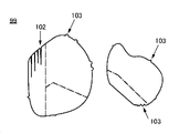
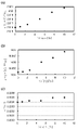
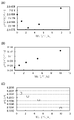
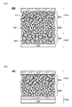
양극 활물질이 가압 또는 충방전의 반복 등으로 인하여 깨지거나, 또는 크랙이 생기면, 전이 금속의 용출, 과잉의 부반응 등이 일어나기 쉬워진다. 양극 활물질은 표면에 크랙, 요철, 단차, 거치름 등이 있으면, 응력이 일부에 집중되기 쉬워져, 깨지기 쉬워진다. 반대로, 표면이 매끄럽고 구형에 가까울수록 응력의 집중이 완화되어 깨지기 어려워진다. 따라서, 표면이 매끄럽고 요철이 적은 양극 활물질로 한다. 예를 들어 현미경 이미지를 사용하여 화상 해석을 수행하였을 때, 면적 포락도의 중앙값이 0.96 이상인 양극 활물질이다. 또는, 프랙탈 차원의 중앙값이 1.143 이하인 양극 활물질이다. 또는, 진원도의 중앙값이 0.7 이상인 양극 활물질이다.When the positive electrode active material is cracked or cracked due to pressurization or repeated charging and discharging, etc., elution of transition metals and excessive side reactions are likely to occur. When the surface of the positive electrode active material has cracks, irregularities, steps, roughness, etc., the stress tends to be concentrated in a part of the positive electrode active material and becomes brittle. Conversely, the smoother and more spherical the surface, the less brittle the stress concentration is. Therefore, it is set as a positive electrode active material with a smooth surface and few unevenness|corrugations. For example, when image analysis is performed using a microscope image, the positive active material has a median area envelope of 0.96 or more. Alternatively, the cathode active material has a median value of the fractal dimension of 1.143 or less. Alternatively, the positive electrode active material has a median of roundness of 0.7 or more.

Description
본 발명의 일 형태는 물건, 방법, 또는 제조 방법에 관한 것이다. 또는, 본 발명은 공정(process), 기계(machine), 제품(manufacture), 또는 조성물(composition of matter)에 관한 것이다. 본 발명의 일 형태는 반도체 장치, 표시 장치, 발광 장치, 이차 전지, 축전 장치, 기억 장치, 전자 기기, 또는 이들의 제조 방법에 관한 것이다. 또한, 본 발명의 일 형태는 반도체 장치, 표시 장치, 발광 장치, 이차 전지, 축전 장치, 기억 장치를 사용하는 차량, 또는 차량에 제공되는 차량용 전자 기기에 관한 것이다.One aspect of the present invention relates to an article, a method, or a manufacturing method. Alternatively, the present invention relates to a process, machine, manufacture, or composition of matter. One embodiment of the present invention relates to a semiconductor device, a display device, a light emitting device, a secondary battery, a power storage device, a storage device, an electronic device, or a manufacturing method thereof. Further, one embodiment of the present invention relates to a vehicle using a semiconductor device, a display device, a light emitting device, a secondary battery, a power storage device, or a storage device, or a vehicle electronic device provided in the vehicle.
또한, 본 명세서 중에서 전자 기기란 축전 장치를 갖는 장치 전반을 가리키고, 축전 장치를 갖는 전기 광학 장치, 축전 장치를 갖는 정보 단말 장치 등은 모두 전자 기기이다.In this specification, an electronic device refers to an overall device having a power storage device, and an electro-optical device having a power storage device, an information terminal device having a power storage device, and the like are all electronic devices.
근년, 리튬 이온 이차 전지, 리튬 이온 커패시터, 공기 전지, 전고체 전지 등, 다양한 축전 장치의 개발이 활발히 진행되고 있다. 특히, 고출력이며 고용량인 리튬 이온 이차 전지는 반도체 산업의 발전에 수반하여 그 수요가 급속히 확대되어, 충전 가능한 에너지의 공급원으로서 현대의 정보화 사회에 불가결한 것이 되었다.In recent years, development of various electrical storage devices, such as a lithium ion secondary battery, a lithium ion capacitor, an air battery, and an all-solid-state battery, is progressing actively. In particular, a high-output and high-capacity lithium ion secondary battery has rapidly expanded its demand with the development of the semiconductor industry, and has become indispensable in the modern information society as a source of rechargeable energy.
그 중에서도 모바일 전자 기기용 이차 전지 등에서는, 중량당 방전 용량이 크고, 사이클 특성이 우수한 이차 전지에 대한 수요가 높다. 이러한 수요에 대응하기 위하여 이차 전지의 양극이 갖는 양극 활물질의 개량이 활발히 진행되고 있다(예를 들어 특허문헌 1 내지 특허문헌 3). 또한, 양극 활물질의 결정 구조에 관한 연구도 진행되고 있다(비특허문헌 1 내지 비특허문헌 3).Among them, in secondary batteries for mobile electronic devices and the like, there is a high demand for secondary batteries having a large discharge capacity per weight and excellent cycle characteristics. In order to respond to such a demand, improvement of the positive electrode active material which the positive electrode of a secondary battery has is actively progressing (for example, patent document 1 - patent document 3). In addition, research on the crystal structure of the positive electrode active material is also in progress (
또한, X선 회절(XRD)은 양극 활물질의 결정 구조를 해석하는 데 사용되는 방법 중 하나이다. 비특허문헌 4에서 소개된 ICSD(Inorganic Crystal Structure Database)를 사용함으로써, XRD 데이터를 해석할 수 있다.In addition, X-ray diffraction (XRD) is one of the methods used to interpret the crystal structure of the positive electrode active material. By using ICSD (Inorganic Crystal Structure Database) introduced in Non-Patent
그러나, 리튬 이온 이차 전지 및 이에 사용되는 양극 활물질에는, 충방전 용량, 사이클 특성, 신뢰성, 안전성, 또는 비용 등의 다양한 면에서 개선의 여지가 남아 있다.However, the lithium ion secondary battery and the positive electrode active material used therein have room for improvement in various aspects such as charge/discharge capacity, cycle characteristics, reliability, safety, or cost.
예를 들어 리튬 이온 이차 전지의 양극을 제작할 때, 일반적으로 양극 활물질층과 양극 집전체를 가압하는 것이 수행된다. 이는 양극 활물질층의 밀도를 높이거나, 또는 양극 집전체와 양극 활물질층을 밀착시킨다는 등의 효과가 있다. 한편으로, 상기 가압으로 인하여 양극 활물질이 깨지는 경우가 있다.For example, when manufacturing a positive electrode of a lithium ion secondary battery, it is generally performed to pressurize the positive electrode active material layer and the positive electrode current collector. This has effects such as increasing the density of the positive electrode active material layer or bringing the positive electrode current collector into close contact with the positive electrode active material layer. On the other hand, the positive electrode active material may be broken due to the pressure.
또한, 이차 전지의 충방전의 반복에 따라 양극 활물질에 크랙, 깨짐 등이 생기는 경우도 있다.In addition, cracks, cracks, etc. may occur in the positive electrode active material due to repeated charging and discharging of the secondary battery.
양극 활물질이 깨지거나, 또는 크랙이 생기면, 전이 금속의 용출, 과잉의 부반응 등이 일어나기 쉬워져, 충방전 용량, 사이클 특성, 신뢰성, 및 안전성 등의 점에서 바람직하지 않다.When the positive electrode active material is broken or cracked, elution of transition metals, excessive side reactions, etc. easily occur, which is not preferable in terms of charge/discharge capacity, cycle characteristics, reliability, and safety.
따라서, 본 발명의 일 형태는 리튬 이온 전지에 사용함으로써, 가압 또는 충방전을 거쳐도 깨지기 어려운 양극 활물질을 제공하는 것을 과제 중 하나로 한다. 또는, 충방전 사이클에 따른 충방전 용량의 저하가 억제된 양극 활물질을 제공하는 것을 과제 중 하나로 한다. 또는, 충방전을 반복하여도 결정 구조가 붕괴되기 어려운 양극 활물질을 제공하는 것을 과제 중 하나로 한다. 또는, 충방전 용량이 큰 양극 활물질을 제공하는 것을 과제 중 하나로 한다. 또는, 안전성 또는 신뢰성이 높은 이차 전지를 제공하는 것을 과제 중 하나로 한다.Therefore, one aspect of the present invention makes it one of the problems to provide a positive electrode active material that is not easily broken even through pressurization or charging and discharging by using it for a lithium ion battery. Another object of the present invention is to provide a positive electrode active material in which a decrease in charge/discharge capacity according to a charge/discharge cycle is suppressed. Alternatively, one of the problems is to provide a positive electrode active material in which the crystal structure is not easily collapsed even after repeated charging and discharging. Alternatively, one of the problems is to provide a positive electrode active material having a large charge/discharge capacity. Alternatively, one of the problems is to provide a secondary battery having high safety or reliability.
또한, 본 발명의 일 형태는 신규 물질, 활물질 입자, 축전 장치, 또는 이들의 제작 방법을 제공하는 것을 과제 중 하나로 한다.Another object of one embodiment of the present invention is to provide a novel material, particles of an active material, a power storage device, or a manufacturing method thereof.
또한, 이들 과제의 기재는 다른 과제의 존재를 방해하는 것은 아니다. 또한, 본 발명의 일 형태는 이들 과제 모두를 해결할 필요는 없는 것으로 한다. 또한, 명세서, 도면, 청구항의 기재로부터 이들 이외의 과제를 추출할 수 있다.In addition, the description of these subjects does not prevent the existence of other subjects. In addition, one aspect of this invention assumes that it is not necessary to solve all these problems. In addition, subjects other than these can be extracted from the description of the specification, drawings, and claims.
상기 과제를 해결하기 위하여, 본 발명의 일 형태에서는 양극 활물질의 형상에 주목하였다. 양극 활물질은 표면에 크랙, 요철, 단차, 거치름 등이 있으면, 응력이 일부에 집중되기 쉬워져, 깨지기 쉬워진다. 반대로, 표면이 매끄럽고 구형에 가까울수록 응력의 집중이 완화되어, 가압 및 충방전을 거쳐도 깨지기 어려워진다. 따라서, 표면이 매끄럽고 요철이 적은 양극 활물질을 제작하기로 하였다.In order to solve the above problem, in one embodiment of the present invention, attention was paid to the shape of the positive electrode active material. When the surface of the positive electrode active material has cracks, irregularities, steps, roughness, etc., the stress tends to be concentrated in a part of the positive electrode active material and becomes brittle. Conversely, as the surface is smoother and closer to a spherical shape, the concentration of stress is relieved, and it becomes difficult to break even through pressurization and charging and discharging. Therefore, it was decided to manufacture a positive electrode active material having a smooth surface and few irregularities.
본 발명의 일 형태는 리튬과 전이 금속을 갖고, 면적 포락도의 중앙값이 0.96 이상인 양극 활물질이다.One embodiment of the present invention is a positive electrode active material having lithium and a transition metal and having a median area coverage of 0.96 or more.
또한, 본 발명의 다른 일 형태는 리튬과 전이 금속을 갖고, 면적 포락도의 제 1 사분위와 제 3 사분위의 차이가 0.04 이하인 양극 활물질이다.Another embodiment of the present invention is a positive electrode active material having lithium and a transition metal, and having a difference between the first and third quartiles of area coverage of 0.04 or less.
또한, 본 발명의 다른 일 형태는 리튬과 전이 금속을 갖고, 프랙탈 차원의 중앙값이 1.143 이하인 양극 활물질이다.Another embodiment of the present invention is a positive electrode active material having lithium and a transition metal and having a median fractal dimension of 1.143 or less.
또한, 본 발명의 다른 일 형태는 리튬과 전이 금속을 갖고, 진원도의 중앙값이 0.7 이상인 양극 활물질이다.Another embodiment of the present invention is a positive electrode active material containing lithium and a transition metal and having a median roundness of 0.7 or more.
상기에서, 양극 활물질은 할로젠을 갖는 것이 바람직하다.In the above, the positive electrode active material preferably has halogen.
상기에서, 할로젠은 플루오린인 것이 더 바람직하다.In the above, the halogen is more preferably fluorine.
상기에서, 양극 활물질은 마그네슘을 갖는 것이 바람직하다.In the above, the positive electrode active material preferably has magnesium.
상기에서, 양극 활물질은 니켈 및 알루미늄을 갖는 것이 바람직하다.In the above, the positive active material preferably has nickel and aluminum.
또한, 본 발명의 다른 일 형태는 앞에서 기재된 양극 활물질을 갖는 이차 전지이다.In addition, another embodiment of the present invention is a secondary battery having the above-described positive active material.
또한, 본 발명의 다른 일 형태는 앞에서 기재된 이차 전지와, 회로 기판, 센서, 및 표시 장치 중 어느 하나를 갖는 전자 기기이다.Another embodiment of the present invention is an electronic device including the secondary battery described above, and any one of a circuit board, a sensor, and a display device.
본 발명의 일 형태에 의하여, 리튬 이온 이차 전지에 사용함으로써, 가압 또는 충방전을 거쳐도 깨지기 어려운 양극 활물질을 제공할 수 있다. 또는, 충방전 사이클에 따른 충방전 용량의 저하가 억제된 양극 활물질을 제공할 수 있다. 또는, 충방전을 반복하여도 결정 구조가 붕괴되기 어려운 양극 활물질을 제공할 수 있다. 또는, 충방전 용량이 큰 양극 활물질을 제공할 수 있다. 또는, 안전성 또는 신뢰성이 높은 이차 전지를 제공할 수 있다.According to one aspect of the present invention, by using for a lithium ion secondary battery, it is possible to provide a positive electrode active material that is not easily broken even through pressurization or charging and discharging. Alternatively, it is possible to provide a positive active material in which a decrease in charge/discharge capacity according to a charge/discharge cycle is suppressed. Alternatively, it is possible to provide a positive electrode active material in which the crystal structure is not easily collapsed even after repeated charging and discharging. Alternatively, a positive electrode active material having a large charge/discharge capacity may be provided. Alternatively, a secondary battery having high safety or reliability may be provided.
또한, 본 발명의 일 형태에 의하여 신규 물질, 활물질 입자, 축전 장치, 또는 이들의 제작 방법을 제공할 수 있다.Moreover, according to one aspect of this invention, a novel material, active material particle|grains, a power storage device, or a manufacturing method thereof can be provided.
또한, 이들 효과의 기재는 다른 효과의 존재를 방해하는 것은 아니다. 또한, 본 발명의 일 형태는 이들 효과 모두를 반드시 가질 필요는 없다. 또한, 이들 이외의 효과는 명세서, 도면, 청구항 등의 기재로부터 저절로 명백해지는 것이며, 명세서, 도면, 청구항 등의 기재로부터 이들 이외의 효과를 추출할 수 있다.In addition, the description of these effects does not prevent the existence of other effects. In addition, one embodiment of the present invention does not necessarily have all of these effects. In addition, effects other than these will become apparent from the description of the specification, drawings, claims, etc., and effects other than these can be extracted from the description of the specification, drawings, claims, and the like.
도 1의 (A)는 양극 활물질의 단면도이다. 도 1의 (B1) 및 (B2)는 양극 활물질의 단면도의 일부이다.
도 2의 (A1) 내지 (C2)는 양극 활물질의 단면도의 일부이다.
도 3은 비교예의 양극 활물질의 단면도이다.
도 4의 (A1) 내지 (B2)는 코발트산 리튬의 계산 모델이다.
도 5의 (A) 내지 (C)는 코발트산 리튬의 계산 모델이다.
도 6은 코발트산 리튬의 산소의 일부를 플루오린으로 치환한 경우의 에너지를 계산한 결과의 그래프이다.
도 7은 양극 활물질의 충전 심도와 결정 구조를 설명하는 도면이다.
도 8은 결정 구조로부터 계산되는 XRD 패턴을 나타낸 도면이다.
도 9는 비교예의 양극 활물질의 충전 심도와 결정 구조를 설명하는 도면이다.
도 10은 결정 구조로부터 계산되는 XRD 패턴을 나타낸 도면이다.
도 11의 (A) 내지 (C)는 XRD로부터 산출되는 격자 상수를 나타낸 것이다.
도 12의 (A) 내지 (C)는 XRD로부터 산출되는 격자 상수를 나타낸 것이다.
도 13은 양극 활물질의 제작 방법을 설명하는 도면이다.
도 14는 양극 활물질의 제작 방법을 설명하는 도면이다.
도 15는 양극 활물질의 제작 방법을 설명하는 도면이다.
도 16은 양극 활물질의 제작 방법을 설명하는 도면이다.
도 17의 (A) 및 (B)는 도전재로서 그래핀 화합물을 사용한 경우의 활물질층의 단면도이다.
도 18의 (A) 및 (B)는 이차 전지의 예를 설명하는 도면이다.
도 19의 (A) 내지 (C)는 이차 전지의 예를 설명하는 도면이다.
도 20의 (A) 및 (B)는 이차 전지의 예를 설명하는 도면이다.
도 21의 (A) 및 (B)는 코인형 이차 전지를 설명하는 도면이다. 도 21의 (C)는 이차 전지에 대하여 설명하는 도면이다.
도 22의 (A) 내지 (D)는 원통형 이차 전지를 설명하는 도면이다.
도 23의 (A) 및 (B)는 이차 전지의 예를 설명하는 도면이다.
도 24의 (A) 내지 (D)는 이차 전지의 예를 설명하는 도면이다.
도 25의 (A) 내지 (C)는 이차 전지의 예를 설명하는 도면이다.
도 26의 (A) 내지 (C)는 이차 전지의 예를 설명하는 도면이다.
도 27의 (A) 내지 (C)는 래미네이트형 이차 전지를 설명하는 도면이다.
도 28의 (A) 및 (B)는 래미네이트형 이차 전지를 설명하는 도면이다.
도 29는 이차 전지의 외관을 도시한 도면이다.
도 30은 이차 전지의 외관을 도시한 도면이다.
도 31의 (A) 내지 (C)는 이차 전지의 제작 방법을 설명하는 도면이다.
도 32의 (A) 내지 (G)는 전자 기기의 일례를 설명하는 도면이다.
도 33의 (A) 내지 (C)는 전자 기기의 일례를 설명하는 도면이다.
도 34는 전자 기기의 일례를 설명하는 도면이다.
도 35의 (A) 내지 (C)는 전자 기기의 일례를 설명하는 도면이다.
도 36의 (A) 내지 (C)는 전자 기기의 일례를 도시한 도면이다.
도 37의 (A) 내지 (C)는 차량의 일례를 설명하는 도면이다.
도 38의 (A) 내지 (C)는 실시예 1의 양극 활물질의 진원도, 면적 포락도, 및 프랙탈 차원의 분포를 나타낸 상자 수염 그림이다.
도 39의 (A) 내지 (C)는 실시예 1의 양극 활물질을 사용한 이차 전지의 25℃에서의 충방전 곡선이다.
도 40의 (A) 내지 (C)는 실시예 1의 양극 활물질을 사용한 이차 전지의 45℃에서의 충방전 곡선이다.
도 41의 (A) 내지 (C)는 실시예 1의 양극 활물질을 사용한 이차 전지의 50℃에서의 충방전 곡선이다.1A is a cross-sectional view of a positive active material. 1 (B1) and (B2) are a part of a cross-sectional view of the positive electrode active material.
2 (A1) to (C2) are a part of a cross-sectional view of the positive electrode active material.
3 is a cross-sectional view of a positive active material of a comparative example.
4 (A1) to (B2) are calculation models of lithium cobaltate.
5A to 5C are calculation models of lithium cobaltate.
6 is a graph showing the result of calculating energy in the case where a part of oxygen in lithium cobaltate is substituted with fluorine.
7 is a view for explaining a filling depth and a crystal structure of a positive electrode active material.
8 is a diagram illustrating an XRD pattern calculated from a crystal structure.
9 is a view for explaining a filling depth and a crystal structure of a positive active material of Comparative Example.
10 is a diagram illustrating an XRD pattern calculated from a crystal structure.
11A to 11C show lattice constants calculated from XRD.
12A to 12C show lattice constants calculated from XRD.
13 is a view for explaining a method of manufacturing a cathode active material.
14 is a view for explaining a method of manufacturing a cathode active material.
15 is a view for explaining a method of manufacturing a positive electrode active material.
16 is a view for explaining a method of manufacturing a cathode active material.
17A and 17B are cross-sectional views of the active material layer when a graphene compound is used as a conductive material.
18A and 18B are views for explaining an example of a secondary battery.
19A to 19C are diagrams for explaining an example of a secondary battery.
20A and 20B are diagrams for explaining an example of a secondary battery.
21A and 21B are diagrams for explaining a coin-type secondary battery. 21C is a view for explaining a secondary battery.
22A to 22D are views for explaining a cylindrical secondary battery.
23A and 23B are diagrams for explaining an example of a secondary battery.
24A to 24D are diagrams for explaining an example of a secondary battery.
25A to 25C are diagrams for explaining an example of a secondary battery.
26A to 26C are diagrams for explaining an example of a secondary battery.
27A to 27C are views for explaining a laminate type secondary battery.
28A and 28B are views for explaining a laminate type secondary battery.
29 is a diagram illustrating an external appearance of a secondary battery.
30 is a diagram illustrating an external appearance of a secondary battery.
31A to 31C are diagrams for explaining a method of manufacturing a secondary battery.
32A to 32G are diagrams for explaining an example of an electronic device.
33A to 33C are diagrams for explaining an example of an electronic device.
It is a figure explaining an example of an electronic device.
35A to 35C are diagrams for explaining an example of an electronic device.
36A to 36C are diagrams showing an example of an electronic device.
37A to 37C are views for explaining an example of a vehicle.
38(A) to (C) are box and whisker diagrams showing the roundness, area envelope, and distribution of fractal dimensions of the positive active material of Example 1. FIG.
39(A) to (C) are charge/discharge curves at 25° C. of a secondary battery using the positive active material of Example 1. FIG.
40A to 40C are charge/discharge curves at 45° C. of a secondary battery using the positive active material of Example 1. FIG.
41A to 41C are charge/discharge curves at 50° C. of a secondary battery using the positive active material of Example 1. FIG.
이하에서는 본 발명의 실시형태에 대하여 도면을 사용하여 자세히 설명한다. 다만, 본 발명은 이하의 설명에 한정되지 않고, 그 형태 및 자세한 사항을 다양하게 변경할 수 있다는 것은 통상의 기술자라면 용이하게 이해할 수 있다. 또한, 본 발명은 이하에 나타내는 실시형태의 기재 내용에 한정하여 해석되는 것은 아니다.DETAILED DESCRIPTION OF THE PREFERRED EMBODIMENTS Hereinafter, embodiments of the present invention will be described in detail with reference to the drawings. However, the present invention is not limited to the following description, and it can be easily understood by those skilled in the art that the form and details can be variously changed. In addition, this invention is limited to description of embodiment shown below, and is not interpreted.
또한, 본 명세서 등에서, 결정면 및 방향의 표기에는 밀러 지수(Miller index)를 사용한다. 결정면을 나타내는 개별 면은 ()로 나타낸다. 결정학에서 결정면, 방향, 및 공간군의 표기는 숫자 위에 바를 붙이지만, 본 명세서 등에서는 출원 표기의 제약상 숫자 위에 바를 붙이는 대신 숫자 앞에 -(마이너스 기호)를 붙여 표현하는 경우가 있다.In addition, in this specification and the like, a Miller index is used to indicate a crystal plane and a direction. Individual faces representing crystal planes are indicated by ( ). In crystallography, the notation of the crystal plane, the direction, and the space group is expressed by adding a bar above the number, but in this specification and the like, there are cases in which a - (minus sign) is added in front of the number instead of adding a bar above the number due to restrictions on the notation of the application.
또한, 본 명세서 등에서, 편재란 어떤 원소의 농도가 다른 영역과 상이한 것을 말한다. 편석, 석출, 불균일, 편중, 농도가 높다 또는 농도가 낮다 등이라고 하여도 좋다.In addition, in this specification and the like, localization means that the concentration of a certain element is different from that of other regions. Segregation, precipitation, non-uniformity, bias, high concentration or low concentration may also be said.
본 명세서 등에서, 균질이란 복수의 원소(예를 들어 A, B, C)로 이루어지는 고체에서 어떤 원소(예를 들어 A)가 같은 특징을 가져 특정 영역에 분포되는 현상을 말한다. 또한, 특정 영역들의 원소 농도가 실질적으로 동일하면 좋다. 예를 들어 특정 영역들의 원소 농도의 차이가 10% 이내이면 좋다. 특정 영역으로서는 예를 들어 표면, 최표면층, 표층부, 볼록부, 오목부, 내부 등이 있다.In the present specification and the like, homogeneity refers to a phenomenon in which a certain element (eg, A) has the same characteristics in a solid composed of a plurality of elements (eg, A, B, C) and is distributed in a specific region. Further, it is sufficient if the element concentrations in the specific regions are substantially the same. For example, the difference in element concentration of specific regions may be within 10%. As a specific area|region, there exist a surface, an outermost layer, a surface layer part, a convex part, a recessed part, an inside, etc., for example.
본 명세서 등에서, 양극 활물질의 표면으로부터 내부를 향하여 10nm 정도까지의 영역을 표층부라고 부른다. 금 또는 크랙에 의하여 생긴 면도 표면이라고 하여도 좋다. 또한, 양극 활물질의 표층부보다 깊은 영역을 내부라고 부른다. 또한, 양극 활물질의 표층부 중, 표면으로부터 내부를 향하여 3nm까지의 영역을 최표면층이라고 부른다. 또한, 양극 활물질의 표면이란, 상기 최표면층을 포함하는 표층부, 및 내부 등을 포함하는, 복합 산화물의 표면을 말한다. 그러므로, 양극 활물질은 제작 후에 화학 흡착된 탄산염, 하이드록시기 등은 포함되지 않는 것으로 한다. 또한, 양극 활물질에 부착된 전해액, 바인더, 도전재, 또는 이들에서 유래하는 화합물도 포함되지 않는 것으로 한다. 또한, 양극 활물질은 반드시 모든 영역이 충방전에 기여하는 리튬 자리를 갖는 영역일 필요는 없다.In this specification and the like, the region from the surface of the positive electrode active material toward the inside to about 10 nm is referred to as a surface layer portion. It may be referred to as a shaving surface caused by cracks or cracks. In addition, a region deeper than the surface layer portion of the positive electrode active material is called an interior. In addition, in the surface layer part of a positive electrode active material, the area|region up to 3 nm from the surface toward the inside is called an outermost layer. In addition, the surface of a positive electrode active material means the surface of the composite oxide containing the surface layer part containing the said outermost layer, and the inside. Therefore, it is assumed that the positive active material does not contain carbonates, hydroxyl groups, etc. chemically adsorbed after fabrication. In addition, electrolyte, binder, conductive material, or compounds derived from these adhering to the positive electrode active material are not included. In addition, the positive active material does not necessarily have to be a region in which all regions have lithium sites contributing to charging and discharging.
본 명세서 등에서, 리튬과 전이 금속 M을 포함하는 복합 산화물이 갖는 층상 암염형 결정 구조란, 양이온과 음이온이 번갈아 배열된 암염형 이온 배열을 갖고, 전이 금속 M과 리튬이 규칙적으로 배열되어 2차원 평면을 형성하기 때문에, 리튬의 2차원적인 확산이 가능한 결정 구조를 말한다. 또한, 일부에 양이온 또는 음이온의 결손 등의 결함이 있어도 좋고, 리튬 이온을 2차원적으로 확산할 수 있으면 좋다. 또한, 층상 암염형 결정 구조는, 엄밀하게 말하자면 암염형 결정의 격자가 변형된 구조를 갖는 경우가 있다.In this specification and the like, the layered rock salt crystal structure of a composite oxide containing lithium and a transition metal M has a rock salt type ion arrangement in which cations and anions are alternately arranged, and the transition metal M and lithium are regularly arranged to form a two-dimensional planar structure. It refers to a crystal structure in which two-dimensional diffusion of lithium is possible. Moreover, defects, such as a defect|deletion of a cation or anion, may exist in a part, and what is necessary is just to be able to diffuse lithium ion two-dimensionally. Strictly speaking, the layered rock salt crystal structure may have a structure in which the lattice of the rock salt crystal is deformed.
또한, 본 명세서 등에서, 암염형 결정 구조란 양이온과 음이온이 번갈아 배열된 구조를 말한다. 또한, 일부에 양이온 또는 음이온의 결손이 있어도 좋다.In addition, in this specification and the like, the rock salt crystal structure refers to a structure in which cations and anions are alternately arranged. Moreover, a defect of a cation or an anion may exist in a part.
또한, 본 명세서 등에서, 혼합물이란 복수의 재료를 혼합한 것을 말한다. 혼합물 중 혼합물이 갖는 원소의 상호 확산이 일어난 후의 물질을 복합물이라고 하여도 좋다. 재료의 일부가 미반응이어도 복합물이라고 하여도 좋다.In addition, in this specification and the like, a mixture refers to a mixture of a plurality of materials. A substance after interdiffusion of the elements of the mixture in the mixture may be referred to as a composite. Even if a part of the material is unreacted, it may be referred to as a composite.
또한, 본 명세서 등에서, 양극 활물질의 이론 용량이란 양극 활물질이 갖는 삽입·이탈 가능한 리튬이 모두 이탈되었을 때의 전기량을 말한다. 예를 들어 LiCoO2의 이론 용량은 274mAh/g이고, LiNiO2의 이론 용량은 274mAh/g이고, LiMn2O4의 이론 용량은 148mAh/g이다.In addition, in this specification and the like, the theoretical capacity of the positive active material refers to the amount of electricity when all of the insertable/removable lithium of the positive active material is released. For example, the theoretical capacity of LiCoO 2 is 274 mAh/g, the theoretical capacity of LiNiO 2 is 274 mAh/g, and the theoretical capacity of LiMn 2 O 4 is 148 mAh/g.
또한, 본 명세서 등에서, 삽입·이탈 가능한 리튬이 모두 삽입되었을 때의 충전 심도를 0으로 하고, 양극 활물질이 갖는 삽입·이탈 가능한 리튬이 모두 이탈되었을 때의 충전 심도를 1로 한다.In this specification and the like, the charging depth when all insertable/removable lithium is inserted is set to 0, and the charging depth when all insertable/removable lithium included in the positive electrode active material is detached is set to 1.
본 명세서 등에서, 양극 활물질에 대해서는 리튬 이온을 이탈시키는 것을 충전이라고 한다.In this specification and the like, the release of lithium ions from the positive electrode active material is referred to as charging.
일반적으로 층상 암염형 결정 구조를 갖는 양극 활물질에서는, 전이 금속 M과 산소로 이루어지는 층상 구조 사이의 리튬이 감소되면, 결정 구조가 불안정해진다. 그러므로, 일반적인 코발트산 리튬을 사용한 이차 전지에서는, 충전 심도 0.4, 충전 전압 4.3V(상대 전극이 리튬인 경우), 충전 용량 160mAh/g 정도까지만 충전할 수 있다.In general, in a positive electrode active material having a layered rock salt crystal structure, when lithium between the layered structure consisting of the transition metal M and oxygen is reduced, the crystal structure becomes unstable. Therefore, in a general secondary battery using lithium cobaltate, it can be charged up to a depth of charge of 0.4, a charge voltage of 4.3 V (when the counter electrode is lithium), and a charge capacity of about 160 mAh/g.
한편으로, 충전 심도가 0.74 이상 0.9 이하, 더 자세하게는 충전 심도가 0.8 이상 0.83 이하의 양극 활물질을 고전압으로 충전된 양극 활물질이라고 한다. 그러므로, 예를 들어 LiCoO2에서, 충전 용량이 219.2mAh/g이면 고전압으로 충전된 양극 활물질이다. 또한, LiCoO2에서, 25℃의 환경에서 충전 전압을 4.525V 이상 4.65V 이하(상대 전극이 리튬인 경우)로 하여 정전류 충전한 후, 전류값이 0.01C, 또는 정전류 충전 시의 전류값의 1/5에서 1/100 정도가 될 때까지 정전압 충전한 후의 양극 활물질도 고전압으로 충전된 양극 활물질이라고 한다. 또한, C는 Capacity rate의 약칭이고, 1C는 이차 전지의 충방전 용량을 1시간에 완전히 충전시키거나 완전히 방전시키는 전류의 크기를 말한다.On the other hand, a positive active material having a charging depth of 0.74 or more and 0.9 or less, more specifically, a positive active material having a charging depth of 0.8 or more and 0.83 or less is referred to as a positive active material charged with a high voltage. Therefore, for example, in LiCoO 2 , if the charging capacity is 219.2 mAh/g, it is a positive electrode active material charged with a high voltage. In addition, in LiCoO 2 , after constant current charging with a charging voltage of 4.525 V or more and 4.65 V or less (when the counter electrode is lithium) in an environment of 25° C., the current value is 0.01 C, or 1 of the current value at the time of constant current charging A positive electrode active material charged with a constant voltage from /5 to 1/100 is also called a positive electrode active material charged with a high voltage. In addition, C is an abbreviation of capacity rate, and 1C refers to the amount of current that fully charges or completely discharges the charge/discharge capacity of the secondary battery in 1 hour.
또한, 양극 활물질에 대해서는 리튬 이온을 삽입하는 것을 방전이라고 한다. 또한, 충전 심도가 0.06 이하의 양극 활물질, 또는 고전압으로 충전된 상태로부터 충전 용량의 90% 이상의 용량이 방전된 양극 활물질을 충분히 방전된 양극 활물질이라고 한다. 예를 들어 LiCoO2에서, 충전 용량이 219.2mAh/g이면 고전압으로 충전된 상태이고, 여기서 충전 용량의 90%인 197.3mAh/g 이상이 방전된 후의 양극 활물질은 충분히 방전된 양극 활물질이다. 또한, LiCoO2에서, 25℃의 환경에서 전지 전압이 3V 이하(상대 전극이 리튬인 경우)가 될 때까지 정전류 방전된 후의 양극 활물질도 충분히 방전된 양극 활물질이라고 한다.In addition, insertion of lithium ions into the positive electrode active material is called discharging. In addition, a positive electrode active material having a charge depth of 0.06 or less, or a positive electrode active material in which 90% or more of the charge capacity is discharged from a state of being charged at a high voltage, is referred to as a sufficiently discharged positive electrode active material. For example, in LiCoO 2 , if the charging capacity is 219.2 mAh/g, it is in a state of being charged at a high voltage, wherein the positive active material after discharging 197.3 mAh/g or more, which is 90% of the charging capacity, is a sufficiently discharged positive active material. In addition, in LiCoO 2 , the positive electrode active material after constant current discharge until the battery voltage becomes 3 V or less (when the counter electrode is lithium) in an environment of 25° C. is also referred to as a sufficiently discharged positive electrode active material.
또한, 본 명세서 등에서, 본 발명의 일 형태의 양극 및 양극 활물질을 사용한 이차 전지로서 상대 전극에 리튬 금속을 사용하는 예를 나타내는 경우가 있지만, 본 발명의 일 형태의 이차 전지는 이에 한정되지 않는다. 음극에 다른 재료, 예를 들어 흑연, 타이타늄산 리튬 등을 사용하여도 좋다. 본 발명의 일 형태의 양극 및 양극 활물질이 갖는, 충방전을 반복하여도 결정 구조가 붕괴되기 어렵고 양호한 사이클 특성을 얻을 수 있다는 등의 성질은 음극의 재료로부터 영향을 받지 않는다. 또한, 본 발명의 일 형태의 이차 전지에 대하여, 상대 전극으로서 리튬을 사용하여 충전 전압을 4.6V 정도의 일반적인 충전 전압보다 높은 전압으로 충방전하는 예를 나타내는 경우가 있지만, 더 낮은 전압으로 충방전하여도 좋다. 더 낮은 전압으로 충방전하는 경우에는 본 명세서 등에서 제시하는 것보다 사이클 특성이 더 좋아지는 것으로 전망된다.In addition, in this specification and the like, there are cases where lithium metal is used as a counter electrode as a secondary battery using the positive electrode and the positive electrode active material of one embodiment of the present invention, but the secondary battery of one embodiment of the present invention is not limited thereto. Other materials, such as graphite, lithium titanate, etc., may be used for the negative electrode. The properties of the positive electrode and positive electrode active material of one embodiment of the present invention that the crystal structure is less likely to collapse even after repeated charging and discharging and good cycle characteristics are obtained are not affected by the material of the negative electrode. In addition, with respect to the secondary battery of one embodiment of the present invention, an example of charging and discharging at a voltage higher than a general charging voltage of about 4.6 V using lithium as a counter electrode is sometimes shown, but charging and discharging at a lower voltage may do In the case of charging and discharging at a lower voltage, cycle characteristics are expected to be better than those presented in this specification and the like.
(실시형태 1)(Embodiment 1)
본 실시형태에서는, 도 1 내지 도 12를 사용하여 본 발명의 일 형태의 양극 활물질에 대하여 설명한다.In this embodiment, the positive electrode active material of one embodiment of this invention is demonstrated using FIGS. 1-12.
도 1의 (A)는 본 발명의 일 형태인 양극 활물질(100)의 단면도이다. 도 1의 (A)에서의 A-B 부근을 확대한 도면을 도 1의 (B1) 및 (B2)에 도시하였다. 도 1의 (A)에서의 C-D 부근을 확대한 도면을 도 2의 (A1) 내지 (C2)에 도시하였다.1A is a cross-sectional view of a positive
도 1의 (A) 내지 도 2의 (C2)에 도시된 바와 같이, 양극 활물질(100)은 표층부(100a)와 내부(100b)를 갖는다. 이들 도면 중에 파선으로 표층부(100a)와 내부(100b)의 경계를 나타내었다. 또한, 도 1의 (A)에 일점파선으로 결정립계의 일부를 나타내었다.As shown in FIGS. 1A to 2C2 , the positive
도 3은 비교예의 양극 활물질(99)의 단면도이다.3 is a cross-sectional view of a positive
<입자의 형상><Shape of Particles>
양극 활물질 입자의 형상은 사이클 특성, 충방전 용량, 신뢰성, 및 안전성 등과 관계가 있다. 예를 들어 도 3에 도시된 비교예의 양극 활물질(99)과 같이, 입자의 표면에 크랙(102), 요철(103) 등이 많이 존재하면, 응력이 집중되는 부분이 생겨, 양극 활물질이 깨지기 쉬워지거나 크랙이 생기기 쉬워질 우려 등이 있다. 양극 활물질이 깨지거나, 또는 크랙이 생기면, 전이 금속 M의 용출, 과잉의 부반응 등이 일어나기 쉬워진다. 이는 사이클 특성, 신뢰성, 및 안전성 등의 점에서 바람직하지 않다.The shape of the positive active material particles is related to cycle characteristics, charge/discharge capacity, reliability, and safety. For example, like the positive electrode
따라서, 본 발명의 일 형태의 양극 활물질은 도 1의 (A)의 양극 활물질(100)과 같이 표면이 매끄러운 것이 바람직하다. 표면이 매끄럽기 때문에 응력의 집중이 완화되어, 가압 및 충방전을 거쳐도 깨지기 어려워진다.Therefore, it is preferable that the positive electrode active material of one embodiment of the present invention has a smooth surface as in the positive electrode
양극 활물질의 표면의 매끄러움은 예를 들어 양극 활물질 입자에서의 현미경 이미지의 화상 해석에 의하여 정량화할 수 있다.The smoothness of the surface of the positive active material can be quantified, for example, by image analysis of a microscope image of the positive active material particles.
현미경 이미지로서는, 예를 들어 표면 SEM 이미지, 단면 SEM 이미지, 단면 TEM 이미지 등을 사용할 수 있다. 또한, 표면 SEM 이미지로부터 추출되는 양극 활물질의 형상은 SEM의 전자선과 수직인 단면 중 하나와 같은 것으로 하여도 좋다. 그러므로, 표면 SEM 이미지로부터 얻은 정량적인 수치를 단면 SEM 이미지, 단면 TEM 이미지의 분석에 적용하여도 좋다. 마찬가지로, 단면 SEM 이미지, 단면 TEM 이미지로부터 얻은 정량적인 수치를 표면 SEM 이미지의 분석에 적용하여도 좋다.As a microscope image, a surface SEM image, a cross-sectional SEM image, a cross-sectional TEM image, etc. can be used, for example. In addition, the shape of the positive electrode active material extracted from the surface SEM image may be the same as one of the cross sections perpendicular to the electron beam of the SEM. Therefore, the quantitative value obtained from the surface SEM image may be applied to the analysis of the cross-sectional SEM image and the cross-sectional TEM image. Similarly, the quantitative values obtained from the cross-sectional SEM image and the cross-sectional TEM image may be applied to the analysis of the surface SEM image.
양극 활물질의 현미경 이미지를 취득할 때에는, 다른 입자와 중첩되지 않고, 하나의 시야 내에 하나의 입자가 들어가는 조건에서 촬영하는 것이 바람직하다. 또한, 입자와 배경의 콘트라스트가 높아지는 관찰 조건에서 촬영하는 것이 바람직하다. 이러한 조건에서 촬영하면, 양극 활물질의 윤곽이 명료해져, 화상 해석 소프트웨어를 사용하여 자동으로 형상을 추출하기 쉬워진다. 그러므로, 화상 해석이 용이해진다. 다만, 이에 한정되지 않고, 양극 활물질의 형상을 명료하게 추출할 수 있으면, 정량화할 수 있다. 예를 들어 뒤에 다른 입자, 도전재, 바인더 등이 존재하는 조건의 경우에는, 형상을 명료하게 추출하기 위하여, 수동으로, 또는 자동과 수동 모두로 형상의 추출을 수행하여도 좋다.When acquiring a microscope image of the positive active material, it is preferable to photograph under the condition that one particle enters one field of view without overlapping with other particles. In addition, it is preferable to shoot under observation conditions in which the contrast between the particles and the background becomes high. When shooting under these conditions, the outline of the positive electrode active material becomes clear, making it easy to automatically extract the shape using image analysis software. Therefore, image analysis becomes easy. However, the present invention is not limited thereto, and as long as the shape of the positive electrode active material can be clearly extracted, it can be quantified. For example, in the case of a condition in which other particles, conductive materials, binders, etc. exist later, in order to extract the shape clearly, the shape extraction may be performed manually or both automatically and manually.
또한, 통계적인 유의차를 얻기 위하여, 랜덤으로 10개 이상의 입자의 현미경 이미지를 취득하는 것이 바람직하다.In addition, in order to obtain a statistically significant difference, it is preferable to randomly acquire microscopic images of 10 or more particles.
화상 해석 소프트웨어로서는 예를 들어 ImageJ를 사용할 수 있다. ImageJ를 사용하여 현미경 이미지로부터 2차원 형상을 추출할 수 있다. 또한, 추출한 입자의 2차원 형상에 대하여 면적을 산출할 수 있다. 또한, 형태 기술자로서, 진원도(Circularity), 면적 포락도(Solidity) 등을 산출할 수 있다. 또한, 현미경 이미지로부터 윤곽을 추출하여, 프랙탈의 박스를 카운트함으로써, 프랙탈 차원을 산출할 수 있다.ImageJ can be used as image analysis software, for example. ImageJ can be used to extract two-dimensional shapes from microscopic images. In addition, the area can be calculated with respect to the two-dimensional shape of the extracted particles. In addition, as a shape descriptor, circularity, area solidity, and the like can be calculated. Also, by extracting the outline from the microscope image and counting the boxes of the fractal, the fractal dimension can be calculated.
진원도는 4π×(면적)/(원둘레)2이다. 본 발명의 일 형태의 양극 활물질은 진원도의 중앙값이 0.70 이상인 것이 바람직하고, 0.75 이상인 것이 더 바람직하다.Roundness is 4π×(area)/(circumference) 2 . It is preferable that the median of roundness is 0.70 or more, and, as for the positive electrode active material of one embodiment of the present invention, it is more preferable that it is 0.75 or more.
면적 포락도는 (면적)/(볼록 껍질 면적)이다. 면적 포락도는 형태의 오목부의 적음을 나타낸다. 또한, 볼록 껍질 면적(Convex Hull)이란, 임의의 영역이 모두 볼록형의 윤곽에 의하여 둘러싸여 있는 영역의 면적이다. 본 발명의 일 형태의 양극 활물질은 면적 포락도의 중앙값이 0.96 이상인 것이 바람직하고, 0.97 이상인 것이 더 바람직하다. 또한, 면적 포락도의 제 1 사분위와 제 3 사분위의 차이가 0.04 이하인 것이 바람직하고, 0.03 이하인 것이 더 바람직하다.Area envelope is (area)/(convex hull area). The area envelope indicates the number of concavities in the shape. In addition, the convex hull area is an area of a region in which all arbitrary regions are surrounded by a convex outline. It is preferable that the median of area coverage is 0.96 or more, and, as for the positive electrode active material of one embodiment of this invention, it is more preferable that it is 0.97 or more. Further, the difference between the first quartile and the third quartile of the area envelope is preferably 0.04 or less, and more preferably 0.03 or less.
프랙탈 차원은 윤곽의 복잡성을 나타낸다. 박스 카운팅법에서는, 대상물의 윤곽을 폭이 1인 픽셀의 흑백 2치의 경계선으로 하였을 때, 박스의 크기를 변경하면서 이를 덮는 데 필요한 박스의 개수를 계측한다. 윤곽선을 덮는 박스의 크기와 개수를 양대수 그래프에 플롯하여, 그 기울기로부터 프랙탈 차원을 산출할 수 있다. 프랙탈 차원 Dboxcount=-(기울기)이다. 본 발명의 일 형태의 양극 활물질은 박스 카운팅법에 의한 프랙탈 차원의 중앙값이 1.143 이하인 것이 바람직하고, 1.141 이하인 것이 더 바람직하다.The fractal dimension represents the complexity of the contour. In the box counting method, when the outline of an object is a boundary line between black and white pixels having a width of 1, the number of boxes required to cover the box is measured while changing the size of the box. By plotting the size and number of boxes covering the contour on a bi-log graph, the fractal dimension can be calculated from the slope. The fractal dimension D boxcount = - (slope). It is preferable that the median value of the fractal dimension by the box counting method is 1.143 or less, and, as for the positive electrode active material of one embodiment of this invention, it is more preferable that it is 1.141 or less.
상기와 같은 범위이면, 표면이 매끄러운 양극 활물질이라고 할 수 있다. 또한, 반드시 모든 파라미터에서 바람직한 범위를 만족시킬 필요는 없다. 상술한 파라미터 중 하나 이상이 바람직한 범위에 있으면, 표면이 충분히 매끄러운 양극 활물질이라고 할 수 있다.If it is within the above range, it can be said that the surface is a smooth positive electrode active material. In addition, it is not always necessary to satisfy the preferred ranges in all parameters. When at least one of the above-mentioned parameters is in a preferable range, it can be said that the surface is a sufficiently smooth positive electrode active material.
<융제 효과><Fusing effect>
상기와 같은 표면이 매끄러운 양극 활물질은 예를 들어 리튬과 전이 금속 M을 갖는 복합 산화물과, 융제로서 기능하는 재료를 혼합하고 가열함으로써 제작하는 것이 바람직하다. 또한, 융제로서 기능하는 재료에 더하여 결정 구조의 안정화에 기여하는 첨가물도 혼합하고 가열함으로써 제작하는 것이 더 바람직하다.The positive electrode active material having a smooth surface as described above is preferably produced by mixing, for example, a composite oxide containing lithium and transition metal M, and a material functioning as a fluxing agent and heating. Further, in addition to the material functioning as a flux, it is more preferable to prepare by mixing and heating an additive that contributes to stabilization of the crystal structure.
표면이 충분히 매끄럽지 않는 리튬과 전이 금속 M을 갖는 복합 산화물이어도, 상기 복합 산화물의 융점 이상의 온도에서 가열하면, 표면의 일부가 용융되어 매끄러운 표면을 갖는 복합 산화물로 할 수 있는 경우가 있다. 그러나, 이러한 고온에서의 가열은 상기 복합 산화물의 일부가 분해되거나 결정 구조가 붕괴된다는 등의 악영향을 미칠 우려가 있다. 복합 산화물의 일부가 분해되거나, 또는 결정 구조가 붕괴되면, 충방전 용량 및 사이클 특성이 악화된다.Even for a composite oxide having lithium and a transition metal M whose surface is not sufficiently smooth, when heated at a temperature equal to or higher than the melting point of the composite oxide, a part of the surface is melted to obtain a composite oxide having a smooth surface. However, heating at such a high temperature may have adverse effects such as the decomposition of a part of the composite oxide or the collapse of the crystal structure. When a part of the composite oxide is decomposed or the crystal structure is collapsed, the charge/discharge capacity and cycle characteristics deteriorate.
따라서, 융제로서 기능하는 재료와, 리튬과 전이 금속 M을 갖는 복합 산화물을 혼합하면, 융제 효과에 의하여 이들의 융점을 낮출 수 있다. 또한, 결정 구조의 안정화에 기여하는 첨가물을 혼합함으로써, 융점이 더 낮아지는 경우도 있다. 그러므로, 복합 산화물의 융점보다 낮은 온도에서 복합 산화물의 표면을 용융시킬 수 있다. 그러므로, 매끄러운 표면을 갖는 양극 활물질로 하면서, 분해, 결정 구조의 붕괴 등을 억제할 수 있다. 그러므로, 충방전 용량 및 사이클 특성이 우수하고, 또한 신뢰성 및 안전성이 높은 양극 활물질로 할 수 있다.Therefore, when a material functioning as a flux is mixed with a composite oxide having lithium and a transition metal M, the melting point thereof can be lowered by the flux effect. Further, by mixing an additive that contributes to stabilization of the crystal structure, the melting point may be lowered further. Therefore, it is possible to melt the surface of the composite oxide at a temperature lower than the melting point of the composite oxide. Therefore, decomposition, collapse of the crystal structure, and the like can be suppressed while providing a positive electrode active material having a smooth surface. Therefore, it can be set as a positive electrode active material which is excellent in charge/discharge capacity and cycle characteristic, and also has high reliability and safety|security.
융제로서 기능하는 재료로서는, 리튬과 전이 금속 M을 갖는 복합 산화물보다 융점이 낮은 재료를 사용하는 것이 바람직하다. 또한, 할로젠화물, 할로젠, 또는 알칼리 금속 화합물을 사용하는 것이 바람직하다. 융제로서 기능하는 재료는 실온에서 고체 또는 액체이면, 혼합이 용이하기 때문에 바람직하지만, 실온에서 기체이어도 좋다. 기체인 경우에는, 가열 공정에서 분위기 중에 혼합하면 좋다.As a material functioning as a flux, it is preferable to use a material having a lower melting point than a composite oxide having lithium and a transition metal M. In addition, it is preferable to use a halide, a halogen, or an alkali metal compound. The material serving as the flux is preferably a solid or liquid at room temperature because mixing is easy, but may be a gas at room temperature. In the case of a gas, it is good to mix in atmosphere in a heating process.
예를 들어 할로젠화물 및 할로젠으로서, 플루오린화 리튬(LiF), 플루오린화 칼슘(CaF2), 플루오린화 소듐(NaF), 플루오린화 포타슘(KF), 플루오린화 바륨(BaF2), 육플루오린화 알루미늄소듐(Na3AlF6), 염화 리튬(LiCl), 염화 마그네슘(MgCl2), 염화 소듐(NaCl), 플루오린(F2), 염소(Cl2), 플루오린화 탄소(CF4, CHF3, CH2F2, CH3F), 염화 탄소(CCl4, CHCl3, CH2Cl2, CH3Cl), 플루오린화 황(S2F2, SF4, SF6, S2F10), 염화 황(SCl2, S2Cl2), 플루오린화 산소(OF2, O2F2, O3F2, O4F2, O2F), 염화 산소(ClO2) 등을 사용할 수 있다. 그 중에서도, 플루오린화 리튬은 융점이 848℃로 비교적 낮고, 가열 공정에서 용융되기 쉽기 때문에, 융제로서 기능하는 재료로서 바람직하다.Lithium fluoride (LiF), calcium fluoride (CaF 2 ), sodium fluoride (NaF), potassium fluoride (KF), barium fluoride (BaF 2 ), hexafluoride, e.g., as halides and halogens Sodium aluminum fluoride (Na 3 AlF 6 ), lithium chloride (LiCl), magnesium chloride (MgCl 2 ), sodium chloride (NaCl), fluorine (F 2 ), chlorine (Cl 2 ), carbon fluoride (CF 4 , CHF) 3 , CH 2 F 2 , CH 3 F), carbon chloride (CCl 4 , CHCl 3 , CH 2 Cl 2 , CH 3 Cl), sulfur fluoride (S 2 F 2 , SF 4 , SF 6 , S 2 F 10 ) ), sulfur chloride (SCl 2 , S 2 Cl 2 ), oxygen fluoride (OF 2 , O 2 F 2 , O 3 F 2 , O 4 F 2 , O 2 F), oxygen chloride (ClO 2 ), etc. can Among them, lithium fluoride has a relatively low melting point of 848° C. and is easily melted in a heating step, and therefore is preferable as a material functioning as a fluxing agent.
또한, 알칼리 금속 화합물로서 탄산 리튬(Li2CO3), 수산화 리튬(LiOH, LiOH·H2O), 산화 리튬(Li2O), 질산 리튬(LiNO3), 탄산 소듐(Na2CO3), 수산화 소듐(NaOH), 산화 소듐(Na2O), 질산 소듐(NaNO3) 등을 사용할 수 있다.In addition, as alkali metal compounds, lithium carbonate (Li 2 CO 3 ), lithium hydroxide (LiOH, LiOH·H 2 O), lithium oxide (Li 2 O), lithium nitrate (LiNO 3 ), sodium carbonate (Na 2 CO 3 ) , sodium hydroxide (NaOH), sodium oxide (Na 2 O), sodium nitrate (NaNO 3 ), and the like may be used.
또한, 상기 재료의 수화물을 사용하여도 좋다. 또한, 복수의 재료를 혼합하여 사용하여도 좋다.Moreover, you may use the hydrate of the said material. In addition, a plurality of materials may be mixed and used.
결정 구조의 안정화에 기여하는 첨가물로서는, 예를 들어 플루오린화 마그네슘, 수산화 마그네슘, 산화 마그네슘 등의 마그네슘 화합물, 플루오린화 알루미늄, 수산화 알루미늄, 산화 알루미늄 등의 알루미늄 화합물, 플루오린화 타이타늄, 수산화 타이타늄, 산화 타이타늄, 질화 타이타늄 등의 타이타늄 화합물, 플루오린화 니켈, 수산화 니켈, 산화 니켈 등의 니켈 화합물, 플루오린화 지르코늄, 산화 지르코늄 등의 지르코늄 화합물, 플루오린화 바나듐 등의 바나듐 화합물, 플루오린화 철, 산화 철 등의 철 화합물, 플루오린화 크로뮴, 산화 크로뮴 등의 크로뮴 화합물, 플루오린화 나이오븀, 산화 나이오븀 등의 나이오븀 화합물, 플루오린화 코발트, 산화 코발트 등의 코발트 화합물, 산화 비소 등의 비소 화합물, 플루오린화 아연, 산화 아연 등의 아연 화합물, 플루오린화 세륨, 산화 세륨 등의 세륨 화합물, 플루오린화 란타넘, 산화 란타넘 등의 란타넘 화합물, 산화 실리콘 등의 실리콘 화합물, 황 및 황 화합물, 인 및 인산 등의 인 화합물, 붕산 등의 붕소 화합물, 플루오린화 망가니즈, 산화 망가니즈 등의 망가니즈 화합물 등을 사용할 수 있다.As an additive contributing to the stabilization of a crystal structure, For example, magnesium compounds, such as magnesium fluoride, magnesium hydroxide, magnesium oxide, aluminum compounds, such as aluminum fluoride, aluminum hydroxide, aluminum oxide, titanium fluoride, titanium hydroxide, titanium oxide , titanium compounds such as titanium nitride, nickel compounds such as nickel fluoride, nickel hydroxide, and nickel oxide, zirconium compounds such as zirconium fluoride and zirconium oxide, vanadium compounds such as vanadium fluoride, iron such as iron fluoride and iron oxide compound, chromium compounds such as chromium fluoride and chromium oxide, niobium compounds such as niobium fluoride and niobium oxide, cobalt compounds such as cobalt fluoride and cobalt oxide, arsenic compounds such as arsenic oxide, zinc fluoride, oxide Zinc compounds such as zinc, cerium compounds such as cerium fluoride and cerium oxide, lanthanum compounds such as lanthanum fluoride and lanthanum oxide, silicon compounds such as silicon oxide, sulfur and sulfur compounds, phosphorus compounds such as phosphorus and phosphoric acid , boron compounds such as boric acid, and manganese compounds such as manganese fluoride and manganese oxide can be used.
또한, 상기 재료의 수화물을 사용하여도 좋다. 또한, 복수의 재료를 혼합하여 사용하여도 좋다. 또한, 본 명세서 등에서는 첨가물을 '혼합물', '원료의 일부', '불순물' 등이라고 부르는 경우가 있다.Moreover, you may use the hydrate of the said material. In addition, a plurality of materials may be mixed and used. In addition, in this specification and the like, additives are sometimes referred to as 'mixtures', 'part of raw materials', 'impurities', and the like.
또한, 융제로서 기능하는 재료와, 결정 구조의 안정화에 기여하는 첨가물을 명확하게 구별할 수 없는 경우도 있다. 어떤 재료가 융제의 기능과 결정 구조의 안정화의 기능을 모두 갖는 경우도 있다. 그러므로, 결정 구조의 안정화에 기여하는 첨가물로서 열거한 것을 융제로서 기능하는 재료로서 사용하여도 좋다. 또한, 융제로서 기능하는 재료로서 열거한 것을 결정 구조의 안정화에 기여하는 첨가물로서 사용하여도 좋다.In addition, there are cases where it is not possible to clearly distinguish between a material functioning as a flux and an additive contributing to the stabilization of the crystal structure. Some materials have both the function of flux and the function of stabilizing the crystal structure. Therefore, those listed as additives contributing to the stabilization of the crystal structure may be used as the material functioning as a fluxing agent. In addition, those listed as materials that function as fluxes may be used as additives contributing to stabilization of the crystal structure.
리튬과 전이 금속 M을 갖는 복합 산화물에는, 예를 들어 층상 암염형 결정 구조, 스피넬형 결정 구조, 올리빈형 결정 구조를 갖는 재료를 사용할 수 있다. 예를 들어 코발트산 리튬, 니켈산 리튬, 코발트의 일부가 망가니즈로 치환된 코발트산 리튬, 코발트의 일부가 니켈로 치환된 코발트산 리튬, 니켈-망가니즈-코발트산 리튬, 인산 철 리튬, 철산 리튬, 망가니즈산 리튬 등의 리튬과 전이 금속 M을 갖는 복합 산화물을 사용할 수 있다. 또한, 양극 활물질로서 기능하는 재료이면, 반드시 리튬을 가질 필요는 없고, V2O5, Cr2O5, MnO2 등을 사용하여도 좋다.For the composite oxide containing lithium and the transition metal M, for example, a material having a layered rock salt crystal structure, a spinel crystal structure, or an olivine type crystal structure can be used. For example, lithium cobaltate, lithium nickelate, lithium cobalt in which a part of cobalt is substituted with manganese, lithium cobalt in which a part of cobalt is substituted with nickel, nickel-manganese-lithium cobalt, lithium iron phosphate, ferric acid Composite oxides having lithium, such as lithium and lithium manganate, and the transition metal M can be used. Moreover, as long as it is a material functioning as a positive electrode active material, it is not necessarily necessary to have lithium, and V2O5 , Cr2O5 , MnO2 , etc. may be used.
<원소의 분포><Distribution of elements>
상기와 같이, 융제로서 기능하는 재료와, 리튬과 전이 금속 M을 갖는 복합 산화물을 혼합한 후 가열하여 제작하면, 양극 활물질의 표층부에 융제로서 기능하는 재료가 갖는 원소의 일부가 편재한다. 또한, 결정 구조의 안정화에 기여하는 첨가물 원소도 혼합하고 가열하여 제작하는 경우, 마찬가지로 첨가물 원소의 일부가 양극 활물질의 표층부에 편재한다.As described above, when a material functioning as a flux and a composite oxide having lithium and transition metal M are mixed and then heated to produce, some of the elements of the material functioning as a flux are unevenly distributed in the surface layer of the positive electrode active material. In addition, when an additive element that contributes to the stabilization of the crystal structure is also mixed and heated to produce, a part of the additive element is also unevenly distributed in the surface layer portion of the positive electrode active material.
그러므로, 양극 활물질(100)은 리튬과, 전이 금속 M과, 산소와, 융제로서 기능하는 재료가 갖는 원소를 갖는다. 또한, 결정 구조의 안정화에 기여하는 첨가물 원소도 갖는 것이 바람직하다.Therefore, the positive electrode
양극 활물질(100)이 갖는 전이 금속 M으로서는, 코발트, 니켈, 망가니즈, 철, 바나듐, 크로뮴 등을 들 수 있다. 특히, 리튬과 함께 공간군 R-3m에 속하는 층상 암염형 복합 산화물을 형성할 수 있는 금속을 사용하는 것이 바람직하다. 예를 들어 망가니즈, 코발트, 니켈 중 적어도 하나를 사용하는 것이 바람직하다. 즉 양극 활물질(100)이 갖는 전이 금속 M으로서 코발트만을 사용하여도 좋고, 니켈만을 사용하여도 좋고, 코발트와 망가니즈의 2종류, 또는 코발트와 니켈의 2종류를 사용하여도 좋고, 코발트, 망가니즈, 니켈의 3종류를 사용하여도 좋다. 즉 양극 활물질(100)은 코발트산 리튬, 니켈산 리튬, 코발트의 일부가 망가니즈로 치환된 코발트산 리튬, 코발트의 일부가 니켈로 치환된 코발트산 리튬, 니켈-망가니즈-코발트산 리튬 등, 리튬과 전이 금속 M을 포함하는 복합 산화물을 가질 수 있다. 전이 금속 M으로서 코발트에 더하여 니켈을 가지면, 고전압의 충전 상태에서 결정 구조가 더 안정되는 경우가 있어 바람직하다. 코발트원과 니켈원의 2종류를 사용하는 경우에는, 코발트와 니켈의 원자수비가 Co:Ni=(1-x):x(0.3<x<0.75)인 것이 바람직하고, (0.4≤x≤0.6)인 것이 더 바람직하다. 이러한 원자수비의 양극 활물질을 사용한 이차 전지는 50℃ 등의 실온보다 높은 환경에서도 양호한 사이클 특성을 나타낸다.Examples of the transition metal M included in the positive electrode
융제로서 기능하는 재료가 갖는 원소로서는, 상술한 바와 같이, 플루오린, 염소 등의 할로젠, 리튬, 칼슘, 소듐, 포타슘, 바륨, 알루미늄, 탄소, 황, 질소 등을 들 수 있다.As mentioned above, as an element which the material functioning as a flux has, halogens, such as fluorine and chlorine, lithium, calcium, sodium, potassium, barium, aluminum, carbon, sulfur, nitrogen, etc. are mentioned.
결정 구조의 안정화에 기여하는 첨가물 원소로서는, 상술한 바와 같이, 마그네슘, 알루미늄, 타이타늄, 니켈, 지르코늄, 바나듐, 철, 크로뮴, 나이오븀, 코발트, 비소, 아연, 세륨, 란타넘, 실리콘, 황, 인, 붕소, 망가니즈 중 적어도 하나를 사용하는 것이 바람직하다. 후술하는 바와 같이, 양극 활물질(100)이 갖는 결정 구조를 이들 원소가 더 안정화시키는 경우가 있다.As the additive element contributing to the stabilization of the crystal structure, as described above, magnesium, aluminum, titanium, nickel, zirconium, vanadium, iron, chromium, niobium, cobalt, arsenic, zinc, cerium, lanthanum, silicon, sulfur, It is preferable to use at least one of phosphorus, boron, and manganese. As will be described later, these elements may further stabilize the crystal structure of the positive electrode
즉 양극 활물질(100)은, 마그네슘 및 플루오린이 첨가된 코발트산 리튬, 마그네슘, 플루오린, 및 타이타늄이 첨가된 코발트산 리튬, 마그네슘 및 플루오린이 첨가된 니켈-코발트산 리튬, 마그네슘 및 플루오린이 첨가된 코발트-알루미늄산 리튬, 니켈-코발트-알루미늄산 리튬, 마그네슘 및 플루오린이 첨가된 니켈-코발트-알루미늄산 리튬, 마그네슘 및 플루오린이 첨가된 니켈-망가니즈-코발트산 리튬 등을 가질 수 있다.That is, the positive electrode
또한, 전이 금속(M)으로서 망가니즈를 반드시 포함할 필요는 없다. 또한, 니켈을 반드시 포함할 필요는 없다. 또한, 철, 바나듐, 또는 크로뮴을 반드시 포함할 필요는 없다.In addition, it is not necessarily necessary to contain manganese as the transition metal (M). In addition, it is not necessarily necessary to include nickel. Also, it need not necessarily contain iron, vanadium, or chromium.
또한, 융제로서 기능하는 재료가 갖는 원소로서 플루오린, 염소 등의 할로젠, 리튬, 마그네슘, 소듐, 포타슘, 바륨, 알루미늄, 탄소, 황, 질소를 반드시 포함할 필요는 없다.In addition, it is not necessary to necessarily contain halogens, such as fluorine and chlorine, lithium, magnesium, sodium, potassium, barium, aluminum, carbon, sulfur, and nitrogen as elements which the material functioning as a fluxing agent has.
또한, 결정 구조의 안정화에 기여하는 첨가물 원소로서 마그네슘, 알루미늄, 타이타늄, 니켈, 지르코늄, 바나듐, 철, 크로뮴, 나이오븀, 코발트, 비소, 아연, 세륨, 란타넘, 실리콘, 황, 인, 붕소, 또는 망가니즈를 반드시 포함할 필요는 없다.In addition, magnesium, aluminum, titanium, nickel, zirconium, vanadium, iron, chromium, niobium, cobalt, arsenic, zinc, cerium, lanthanum, silicon, sulfur, phosphorus, boron, or manganese is not necessarily included.
융제로서 기능하는 재료가 갖는 원소의 일부 및 첨가물 원소의 일부는 도 1의 (B1) 및 (B2)에 그러데이션으로 나타낸 바와 같이 분포되는 것이 바람직하다.It is preferable that a part of the element and a part of the additive element of the material functioning as a flux are distributed as shown by gradations in Figs. 1 (B1) and (B2).
예를 들어 어떤 원소 X는 도 1의 (B1)에 그러데이션으로 나타낸 바와 같이, 내부(100b)로부터 표면을 향하여 높아지는 농도 구배를 갖는 것이 바람직하다. 이러한 농도 구배를 갖는 것이 바람직한 원소 X로서, 예를 들어 마그네슘, 플루오린, 염소 등의 할로젠, 타이타늄, 실리콘, 인, 붕소, 및 칼슘 등이 있다.For example, it is preferable that a certain element X has a concentration gradient that increases from the inside 100b toward the surface, as shown by a gradation in FIG. 1B1 . As the element X preferably having such a concentration gradient, there are, for example, halogens such as magnesium, fluorine, chlorine, titanium, silicon, phosphorus, boron, and calcium.
다른 원소 Y는 도 1의 (B2)에 그러데이션으로 나타낸 바와 같이, 농도 구배를 가지며 도 1의 (B1)보다 깊은 영역에 농도의 피크를 갖는 것이 바람직하다. 농도의 피크는 표층부에 존재하여도 좋고, 표층부보다 깊은 영역에 있어도 좋다. 예를 들어 표면으로부터 5nm 이상 30nm까지의 영역에 피크를 갖는 것이 바람직하다. 이러한 농도 구배를 갖는 것이 바람직한 원소 Y로서, 예를 들어 알루미늄 및 망가니즈가 있다.The other element Y preferably has a concentration gradient as shown by a gradation in FIG. 1(B2) and has a concentration peak in a region deeper than that of FIG. The concentration peak may exist in the surface layer part, and may exist in the area|region deeper than the surface layer part. For example, it is preferable to have a peak in the area|region from 5 nm or more to 30 nm from the surface. Preferred elements Y having such a concentration gradient include, for example, aluminum and manganese.
본 발명의 일 형태의 양극 활물질(100)에서는, 충전에 의하여 양극 활물질(100)에서 리튬이 빠져도, 전이 금속 M과 산소의 팔면체로 이루어지는 층상 구조가 붕괴되지 않도록 첨가물의 농도가 높은 표층부(100a), 즉 입자의 외주부가 보강되어 있다.In the positive electrode
또한, 첨가물의 농도 구배는, 양극 활물질(100)의 표층부(100a)에 균질하게 존재하는 것이 바람직하다. 표층부(100a)의 일부에 보강이 있어도, 보강이 없는 부분이 존재하면, 보강이 없는 부분에 응력이 집중될 우려가 있다. 입자의 일부에 응력이 집중되면 거기서 크랙 등의 결함이 생겨, 양극 활물질의 깨짐 및 충방전 용량의 저하로 이어질 우려가 있다.In addition, it is preferable that the concentration gradient of the additive is uniformly present in the
다만, 반드시 양극 활물질(100)의 표층부(100a) 전체에서 모두의 첨가물의 농도 구배가 균질할 필요는 없다. 도 1의 (A)에서의 C-D 부근의 원소 X의 분포의 예를 도 2의 (A1), (B1), 및 (C1)에 도시하였다. C-D 부근의 원소 Y의 분포의 예를 도 2의 (A2), (B2), 및 (C2)에 도시하였다.However, the concentration gradient of all additives in the entire
예를 들어 도 2의 (A1) 및 (A2)에 도시된 바와 같이, 원소 X 및 원소 Y가 존재하지 않는 영역이 있어도 좋다. 또한, 도 2의 (B1) 및 (B2)에 도시된 바와 같이, 원소 X는 존재하지만, 원소 Y가 존재하지 않는 영역이 있어도 좋다. 또한, 도 2의 (C1) 및 (C2)에 도시된 바와 같이, 원소 X는 존재하지 않지만, 원소 Y가 존재하는 영역이 있어도 좋다. 도 2의 (C2)에서의 원소 Y는 도 1의 (B2)와 마찬가지로 최표면층이 아닌 영역에 피크를 갖는 것이 바람직하다. 예를 들어 표면으로부터 3nm를 초과 30nm까지의 영역에 피크를 갖는 것이 바람직하다.For example, as shown in Figs. 2 (A1) and (A2), there may be regions in which the elements X and Y do not exist. Further, as shown in Figs. 2 (B1) and (B2), there may be a region in which the element X is present but the element Y is not present. Further, as shown in Figs. 2 (C1) and (C2), there may be a region in which the element X is not present, but the element Y is present. It is preferable that the element Y in FIG. 2(C2) has a peak in a region other than the outermost layer as in FIG. 1(B2). For example, it is preferable to have a peak in the region from the surface to more than 3 nm and up to 30 nm.
원소 X 중 하나인 마그네슘은 2가(價)이며, 층상 암염형 결정 구조에서의 전이 금속 M 자리보다 리튬 자리에 존재하는 것이 더 안정적이기 때문에, 리튬 자리에 들어가기 쉽다. 마그네슘이 표층부(100a)의 리튬 자리에 적절한 농도로 존재함으로써 층상 암염형 결정 구조를 유지하기 쉽게 할 수 있다. 마그네슘은 적절한 농도이면 충방전에 따른 리튬의 삽입 및 이탈에 악영향을 미치지 않아 바람직하다. 그러나, 마그네슘이 과잉으로 포함되면, 리튬의 삽입 및 이탈에 악영향을 미칠 우려가 있다.Magnesium, which is one of the elements X, is divalent, and since it is more stable to exist at the lithium site than the transition metal M site in the layered rock salt crystal structure, it is easy to enter the lithium site. When magnesium is present in an appropriate concentration at the lithium site of the
원소 Y 중 하나인 알루미늄은 3가이며, 산소와의 결합력이 강하다. 그러므로, 첨가물로서 알루미늄을 가지면, 알루미늄이 리튬 자리에 들어갔을 때 결정 구조의 변화가 억제될 수 있다. 그러므로, 충방전을 반복하여도 결정 구조가 붕괴되기 어려운 양극 활물질(100)로 할 수 있다.Aluminum, which is one of the elements Y, is trivalent and has a strong bonding force with oxygen. Therefore, having aluminum as an additive can suppress the change in crystal structure when aluminum enters the lithium site. Therefore, it is possible to obtain the positive electrode
이차 전지의 충전 전압의 상승에 따라, 양극의 전압은 일반적으로 상승된다. 본 발명의 일 형태의 양극 활물질은 높은 전압에서도 안정적인 결정 구조를 갖는다. 충전 상태에서 양극 활물질의 결정 구조가 안정되면, 충방전의 반복에 따른 충방전 용량의 저하를 억제할 수 있다.As the charging voltage of the secondary battery rises, the voltage of the positive electrode generally rises. The positive active material of one embodiment of the present invention has a stable crystal structure even at a high voltage. When the crystal structure of the positive electrode active material is stable in a charged state, it is possible to suppress a decrease in charge/discharge capacity due to repeated charge/discharge cycles.
또한, 이차 전지의 내부 단락은 이차 전지의 충전 동작 및 방전 동작에서의 문제를 일으킬 뿐만 아니라, 발열 및 발화를 일으킬 우려가 있다. 안전한 이차 전지를 실현하기 위해서는 높은 충전 전압에서도 내부 단락이 발생되지 않는 것이 바람직하다. 본 발명의 일 형태의 양극 활물질(100)은 높은 충전 전압에서도 내부 단락이 발생되기 어렵다. 그러므로, 높은 충방전 용량과 안전성을 양립한 이차 전지로 할 수 있다.In addition, an internal short circuit of the secondary battery may cause problems in the charging operation and discharging operation of the secondary battery, as well as heat generation and ignition. In order to realize a safe secondary battery, it is desirable that an internal short circuit does not occur even at a high charging voltage. In the positive electrode
본 발명의 일 형태의 양극 활물질(100)을 사용한 이차 전지는 높은 충방전 용량, 우수한 충방전 사이클 특성, 및 안전성을 동시에 만족시키는 것이 바람직하다.It is preferable that the secondary battery using the positive electrode
융제로서 기능하는 재료가 갖는 원소의 일부 및 결정 구조의 안정화에 기여하는 첨가물 원소의 일부의 농도 구배는 예를 들어 에너지 분산형 X선 분광법(EDX: Energy Dispersive X-ray Spectroscopy), 전자 프로브 마이크로 분석법(EPMA) 등을 사용하여 평가할 수 있다. EDX 측정 및 EPMA 측정 중, 영역 내를 주사하면서 측정하고, 영역 내를 2차원적으로 평가하는 것을 면 분석이라고 부르는 경우가 있다. 또한, 면 분석에서 선상의 영역의 데이터를 추출하고, 원자 농도에 대하여 양극 활물질 입자 내의 분포를 평가하는 것을 선 분석이라고 부르는 경우가 있다.The concentration gradient of a part of the element that the material that functions as a flux has and part of the additive element that contributes to stabilization of the crystal structure is, for example, Energy Dispersive X-ray Spectroscopy (EDX), electron probe microanalysis (EPMA), etc. can be used for evaluation. Among the EDX measurement and the EPMA measurement, measuring while scanning the inside of the area and evaluating the inside of the area two-dimensionally is sometimes called surface analysis. Also, in some cases, extracting the data of the linear region from the plane analysis and evaluating the distribution in the positive electrode active material particles with respect to the atomic concentration is called a linear analysis.
EDX 또는 EPMA 면 분석(예를 들어 원소 매핑)에 의하여 양극 활물질(100)의 표층부(100a), 내부(100b), 및 결정립계 근방 등에서의 첨가물의 농도를 정량적으로 분석할 수 있다. 또한, EDX 또는 EPMA 선 분석에 의하여 원소 농도의 피크를 분석할 수 있다.By EDX or EPMA surface analysis (eg, element mapping), the concentration of additives in the
양극 활물질(100)에 대하여 선 분석을 수행하였을 때, 표층부(100a)의 마그네슘 농도의 피크는 양극 활물질(100)의 표면으로부터 중심을 향하여 깊이 3nm까지에 존재하는 것이 바람직하고, 깊이 1nm까지에 존재하는 것이 더 바람직하고, 깊이 0.5nm까지에 존재하는 것이 더욱 바람직하다.When line analysis is performed on the positive
또한, 양극 활물질(100)이 갖는 플루오린의 분포는 마그네슘의 분포와 중첩되는 것이 바람직하다. 그러므로, 선 분석을 수행하였을 때, 표층부(100a)의 플루오린 농도의 피크는 양극 활물질(100)의 표면으로부터 중심을 향하여 깊이 3nm까지에 존재하는 것이 바람직하고, 깊이 1nm까지에 존재하는 것이 더 바람직하고, 깊이 0.5nm까지에 존재하는 것이 더욱 바람직하다.In addition, it is preferable that the distribution of fluorine in the positive electrode
양극 활물질(100)이 알루미늄을 갖는 경우에는, 선 분석을 수행하였을 때, 표층부(100a)의 알루미늄 농도의 피크보다 마그네슘 농도의 피크가 표면에 가까운 것이 바람직하다. 예를 들어 알루미늄 농도의 피크는 양극 활물질(100)의 표면으로부터 중심을 향하여 깊이 0.5nm 이상 50nm 이하에 존재하는 것이 바람직하고, 깊이 5nm 이상 30nm 이하에 존재하는 것이 더 바람직하다. 또는, 0.5nm 이상 30nm 이하에 존재하는 것이 바람직하다. 또는, 5nm 이상 50nm 이하에 존재하는 것이 바람직하다.When the positive
또한, EDX 또는 EPMA 선 분석 결과에서의 양극 활물질(100)의 표면은, 예를 들어 이하와 같이 추정할 수 있다. 양극 활물질(100)의 내부(100b)에서 균일하게 존재하는 원소, 예를 들어 산소 또는 코발트 등의 전이 금속 M에 대하여, 내부의 검출량의 1/2이 된 지점을 표면으로 한다.In addition, the surface of the positive electrode
양극 활물질(100)은 복합 산화물이기 때문에, 산소의 검출량을 사용하여 표면을 추정하는 것이 바람직하다. 구체적으로는, 우선 내부(100b)의 산소의 검출량이 안정적인 영역으로부터 산소 농도의 평균값 Oave를 산출한다. 이때, 표면보다 외측에, 화학 흡착 또는 백그라운드가 원인이 되어 발생한 것으로 생각되는 산소 Obackground가 검출되는 경우에는, 측정값으로부터 Obackground를 뺌으로써, 산소 농도의 평균값 Oave를 얻을 수 있다. 이 평균값(Oave)의 1/2의 값, 즉 1/2Oave와 가장 가까운 측정값을 나타낸 측정점을 양극 활물질의 표면으로 추정할 수 있다.Since the positive electrode
양극 활물질(100)이 갖는 전이 금속 M을 사용하여 표면을 추정할 수도 있다. 예를 들어 전이 금속 M의 95% 이상이 코발트인 경우에는, 코발트의 검출량을 사용하여 상기와 마찬가지로 표면을 추정할 수 있다. 또는, 복수의 전이 금속 M의 검출량의 합을 사용하여 마찬가지로 추정할 수 있다. 전이 금속 M의 검출량은 화학 흡착의 영향을 받기 어려운 점에서 표면을 추정하는 데 적합하다.The surface may be estimated using the transition metal M of the positive
예를 들어 첨가물이 마그네슘이고, 전이 금속 M이 코발트인 경우에는, 마그네슘과 코발트의 원자수의 비율(Mg/Co)은 0.020 이상 0.50 이하인 것이 바람직하다. 0.025 이상 0.30 이하인 것이 더 바람직하다. 0.030 이상 0.20 이하인 것이 더욱 바람직하다. 또는, 0.020 이상 0.30 이하인 것이 바람직하다. 또는, 0.020 이상 0.20 이하인 것이 바람직하다. 또는, 0.025 이상 0.50 이하인 것이 바람직하다. 또는, 0.025 이상 0.20 이하인 것이 바람직하다. 또는, 0.030 이상 0.50 이하인 것이 바람직하다. 또는, 0.030 이상 0.30 이하인 것이 바람직하다.For example, when the additive is magnesium and the transition metal M is cobalt, the ratio of the number of atoms of magnesium to cobalt (Mg/Co) is preferably 0.020 or more and 0.50 or less. It is more preferable that they are 0.025 or more and 0.30 or less. It is more preferable that they are 0.030 or more and 0.20 or less. Or, it is preferable that they are 0.020 or more and 0.30 or less. Or, it is preferable that they are 0.020 or more and 0.20 or less. Or, it is preferable that they are 0.025 or more and 0.50 or less. Or, it is preferable that they are 0.025 or more and 0.20 or less. Or, it is preferable that they are 0.030 or more and 0.50 or less. Or, it is preferable that they are 0.030 or more and 0.30 or less.
<플루오린의 편재><The ubiquity of fluorine>
양극 활물질(100)이 도 1의 (B1)에 도시된 바와 같은, 내부(100b)로부터 표면을 향하여 높아지는 농도 구배를 갖는 것이 바람직한 원소 X 중 하나인 플루오린을 갖는 경우에 대하여 표층부와 내부의 모델을 작성하여 에너지를 비교하였다.The positive
표면 에너지 Es는 하기 식(1)에 의하여 산출할 수 있다.The surface energy E s can be calculated by the following formula (1).
[수학식 1][Equation 1]
![]()
![]()
식(1)의 Esurf는 표면 모델의 총 에너지, Ebulk는 벌크 모델의 총 에너지, S는 표면적을 나타낸다. 이 식으로부터 표면이 안정적일수록 표면 에너지가 작아지는 것을 알 수 있다.In Equation (1), E surf is the total energy of the surface model, E bulk is the total energy of the bulk model, and S is the surface area. From this formula, it can be seen that the more stable the surface, the smaller the surface energy.
이하에서는, 리튬과 전이 금속 M을 갖는 복합 산화물이 코발트산 리튬(LiCoO2)인 것으로 하여 설명한다. 우선, F를 갖지 않는 공간군 R-3m의 LiCoO2에 대하여 표면에 어느 결정면이 나타나기 쉬운지를 조사하기 위하여, (100)면, (102)면, (1-20)면, (104)면, (001)면을 선택하고, 각 면의 표면 에너지를 계산하였다. 계산 조건을 표 1에 나타낸다.Hereinafter, it is assumed that the composite oxide having lithium and the transition metal M is lithium cobaltate (LiCoO 2 ). First, in order to investigate which crystal planes are likely to appear on the surface of LiCoO 2 in the space group R-3m having no F, (100) planes, (102) planes, (1-20) planes, (104) planes, (001) planes were selected, and the surface energy of each plane was calculated. Table 1 shows the calculation conditions.
[표 1][Table 1]

계산 모델의 예를 도 4의 (A1) 내지 (B2)에 나타내었다. 도 4의 (A1)은 벌크, 즉 내부의 모델이고 도면 중의 화살표와 수직으로 (104)면이 존재한다. 도 4의 (A2)는 표면을 포함하는 영역, 즉 표층부의 모델이고 표면에 (104)면이 노출되어 있다. 도 4의 (B1)은 내부 모델이고 도면 중의 화살표와 수직으로 (001)면이 존재한다. 도 4의 (B2)는 표층부 모델이고 표면에 (001)면이 노출되어 있다. 표층부 모델은 벌크 모델의 면 방향으로 총 20Å의 진공 영역(90)을 제공함으로써 작성하였다.Examples of the calculation model are shown in (A1) to (B2) of FIG. 4 . Fig. 4 (A1) is a bulk, that is, an internal model, and the (104) plane is perpendicular to the arrow in the figure. Fig. 4 (A2) is a model of the region including the surface, that is, the surface layer portion, and the (104) plane is exposed on the surface. (B1) of FIG. 4 is an internal model, and the (001) plane exists perpendicularly to the arrow in the figure. Fig. 4 (B2) is a model of the surface layer, and the (001) surface is exposed on the surface. The surface layer model was created by providing a
잘라낸 면 각각의 표면 에너지를 계산한 결과를 표 2에 나타낸다.Table 2 shows the results of calculating the surface energy of each of the cut faces.
[표 2][Table 2]

표 2에 나타낸 바와 같이, 표면 에너지가 작아지기 쉬운 면은 (104)면 및 (001)면인 것이 판명되었다. 이들 면은 안정화되고 표면에 노출되기 쉬운 것으로 생각된다.As shown in Table 2, it was found that the surfaces in which the surface energy tends to become small are the (104) plane and the (001) plane. These surfaces are believed to be stabilized and susceptible to surface exposure.
다음으로, 가장 표면 에너지가 작은 (104)면에서, F 원소가 존재하는 경우의 표면 에너지를 계산하였다. (104)면 중 하나의 면 내에 존재하는 24개의 O 원소의 일부를 F 원소로 치환하였다. 치환한 개수는 하나, 6개, 12개의 3가지이다. 하나를 치환한 경우의 계산 모델을 도 5의 (A)에, 6개를 치환한 경우의 계산 모델을 도 5의 (B)에, 12개를 치환한 경우의 계산 모델을 도 5의 (C)에 나타내었다. 도 5의 (A) 내지 (C)는 (104)면을 수직 방향에서 본 원자 배치이다. F 원소로 치환한 위치를 동그라미로 둘러쌌다.Next, on the (104) plane with the smallest surface energy, the surface energy in the case where the F element is present was calculated. Some of the 24 O elements present in one of the (104) planes were substituted with F elements. The number of substitutions is three, one, six, and twelve. The calculation model in the case of substituting one is shown in Fig. 5 (A), the calculation model in the case of substituting 6 is shown in Fig. 5 (B), and the calculation model in the case of substituting 12 is shown in Fig. ) is shown. 5A to 5C show the arrangement of atoms when the (104) plane is viewed from the vertical direction. The positions substituted with the F element are surrounded by a circle.
O 원소를 F 원소로 치환한 경우의 코발트산 리튬의 표면 에너지의 계산값을 표 3에 나타낸다.Table 3 shows the calculated values of the surface energy of lithium cobaltate when element O is replaced with element F.
[표 3][Table 3]

표 3에 나타낸 바와 같이, 표면 에너지는 F 원소로 치환한 개수가 증가함에 따라 작아지는 경향이 있다. 표층부 모델과 내부 모델의 총 에너지를 플롯한 그래프를 도 6에 나타내었다.As shown in Table 3, the surface energy tends to decrease as the number of substitutions with the F element increases. A graph plotting the total energy of the surface layer model and the internal model is shown in FIG. 6 .
도 6에 나타낸 바와 같이, F 원소로 치환한 개수가 증가할수록, 표층부 모델과 내부 모델의 총 에너지가 모두 불안정화되어 있는 것을 알 수 있다. 그러나, 불안정화의 비율은 내부 모델이 더 크기 때문에, 이들의 차이에 상당하는 표면 에너지는 작아진다. 이 결과로부터, F 원소는 LiCoO2 내부에 존재하면 불안정하고 표면에 편재하기 쉬운 것으로 생각된다.As shown in FIG. 6 , it can be seen that as the number of substitutions with the F element increases, the total energy of both the surface layer model and the internal model is destabilized. However, since the rate of destabilization is larger in the internal model, the surface energy corresponding to their difference becomes smaller. From this result, when the element F exists inside LiCoO2, it is thought that it is unstable and tends to be localized on the surface.
그러므로, 표층부에 플루오린이 편재하는 양극 활물질은 가열을 거쳐 원소의 상호 확산이 충분히 일어난 후의 양극 활물질이라고 할 수도 있다.Therefore, the positive electrode active material in which fluorine is ubiquitous in the surface layer portion can be said to be a positive electrode active material after sufficient interdiffusion of elements has occurred through heating.
<결정 구조><Crystal structure>
도 7 내지 도 12를 사용하여 양극 활물질의 내부(100b)의 결정 구조에 대하여 설명한다.The crystal structure of the inside 100b of the positive electrode active material will be described with reference to FIGS. 7 to 12 .
코발트산 리튬(LiCoO2) 등, 층상 암염형 결정 구조를 갖는 재료는 방전 용량이 높아, 이차 전지의 양극 활물질로서 우수한 것이 알려져 있다. 층상 암염형 결정 구조를 갖는 재료로서 예를 들어 LiMO2로 나타내어지는 복합 산화물을 들 수 있다. 또한, 본 명세서 등에서 LiMO2로 나타내어지는 리튬 복합 산화물은 층상 암염형의 결정 구조를 가지면 좋고, 그 조성은 Li:M:O=1:1:2에 엄밀하게 한정되는 것은 아니다. 도 7 내지 도 12에서는, 양극 활물질이 갖는 전이 금속 M으로서 코발트를 사용하는 경우에 대하여 설명한다.It is known that a material having a layered rock salt crystal structure such as lithium cobaltate (LiCoO 2 ) has a high discharge capacity and is excellent as a positive electrode active material for a secondary battery. As a material which has a layered rock salt type crystal structure, the composite oxide represented, for example by LiMO2 is mentioned. In addition, the lithium composite oxide represented by LiMO 2 in the present specification and the like may have a layered rock salt crystal structure, and its composition is not strictly limited to Li:M:O=1:1:2. 7 to 12 , a case in which cobalt is used as the transition metal M of the positive electrode active material will be described.
전이 금속 화합물에서의 얀-텔러 효과는 전이 금속의 d궤도의 전자수에 따라, 그 효과의 크기가 다른 것이 알려져 있다.It is known that the magnitude of the Jan-Teller effect in transition metal compounds differs depending on the number of electrons in the d orbital of the transition metal.
니켈을 갖는 화합물에서는 얀-텔러 효과로 인하여 변형이 발생하기 쉬운 경우가 있다. 따라서 LiNiO2에서, 고전압으로의 충방전을 수행한 경우, 변형에 기인하여 결정 구조의 붕괴가 생길 우려가 있다. LiCoO2에서는, 얀-텔러 효과의 영향이 작은 것이 시사되기 때문에, 고전압으로 충전되었을 때의 내성이 더 우수한 경우가 있어 바람직하다.In a compound having nickel, there are cases where deformation tends to occur due to the Jan-Teller effect. Therefore, when charging and discharging to a high voltage is performed in LiNiO 2 , there is a risk that the crystal structure may be collapsed due to deformation. In LiCoO 2 , since it is suggested that the influence of the Jan-Teller effect is small, the tolerance at the time of being charged with a high voltage may be more excellent, and it is preferable.
<종래의 양극 활물질><Conventional cathode active material>
도 9에 나타낸 양극 활물질은 후술하는 제작 방법에서 할로젠 및 마그네슘이 첨가되지 않는 코발트산 리튬(LiCoO2)이다. 도 9에 나타낸 코발트산 리튬은 비특허문헌 1 및 비특허문헌 2 등에 기재된 바와 같이 충전 심도에 따라 결정 구조가 변화된다.The positive active material shown in FIG. 9 is lithium cobaltate (LiCoO 2 ) to which halogen and magnesium are not added in a manufacturing method to be described later. As described in
도 9에 나타낸 바와 같이, 충전 심도가 0(방전 상태)인 코발트산 리튬은 공간군 R-3m의 결정 구조를 갖는 영역을 갖고, 단위 격자 중에 CoO2층이 3층 존재한다. 그러므로, 이 결정 구조를 O3형 결정 구조라고 부르는 경우가 있다. 또한, CoO2층이란 코발트에 산소가 6배위한 팔면체 구조가 모서리 공유 상태로 평면에서 연속한 구조를 말한다.As shown in FIG. 9 , lithium cobaltate having a charge depth of 0 (discharged state) has a region having a crystal structure of space group R-3m, and three CoO 2 layers exist in the unit lattice. Therefore, this crystal structure is sometimes called an O3 type crystal structure. In addition, the CoO 2 layer refers to a structure in which an octahedral structure with 6 times oxygen in cobalt is continuous in a plane with a shared edge state.
또한, 충전 심도가 1일 때에는 공간군 P-3m1의 결정 구조를 갖고, 단위 격자 내에 CoO2층이 1층 존재한다. 그러므로, 이 결정 구조를 O1형 결정 구조라고 부르는 경우가 있다.In addition, when the filling depth is 1, it has a crystal structure of the space group P-3m1, and one CoO 2 layer exists in the unit lattice. Therefore, this crystal structure is sometimes called an O1-type crystal structure.
또한, 충전 심도가 0.8 정도일 때의 코발트산 리튬은 공간군 R-3m의 결정 구조를 갖는다. 이 구조는, P-3m1(O1)과 같은 CoO2 구조와 R-3m(O3)과 같은 LiCoO2 구조가 번갈아 적층된 구조라고도 할 수 있다. 그러므로, 이 결정 구조를 H1-3형 결정 구조라고 부르는 경우가 있다. 또한, 실제로는 H1-3형 결정 구조는 단위 격자당 코발트 원자의 수가 다른 구조의 2배이다. 그러나, 도 9를 비롯하여 본 명세서에서는 다른 구조와 비교하기 쉽게 하기 위하여, H1-3형 결정 구조의 c축을 단위 격자의 1/2로 한 도면으로 나타내었다.In addition, lithium cobaltate at a charging depth of about 0.8 has a crystal structure of space group R-3m. This structure can also be referred to as a structure in which a CoO 2 structure such as P-3m1(O1) and a LiCoO 2 structure such as R-3m(O3) are alternately stacked. Therefore, this crystal structure is sometimes called an H1-3 type crystal structure. Also, in reality, the H1-3 type crystal structure has twice the number of cobalt atoms per unit cell than other structures. However, in the present specification, including FIG. 9, the c-axis of the H1-3-type crystal structure is shown as 1/2 of the unit lattice in order to facilitate comparison with other structures.
H1-3형 결정 구조는 일례로서, 비특허문헌 3에 기재가 있는 바와 같이, 단위 격자에서의 코발트와 산소의 좌표를 Co(0, 0, 0.42150±0.00016), O1(0, 0, 0.27671±0.00045), O2(0, 0, 0.11535±0.00045)로 나타낼 수 있다. O1 및 O2는 각각 산소 원자이다. 이와 같이, H1-3형 결정 구조는 하나의 코발트 및 2개의 산소를 사용한 단위 격자로 나타내어진다. 한편으로, 후술하는 바와 같이, 본 발명의 일 형태의 O3'형 결정 구조는 바람직하게는 하나의 코발트 및 하나의 산소를 사용한 단위 격자로 나타내어진다. 이는 O3' 구조의 경우와 H1-3형 구조의 경우에서, 코발트와 산소의 대칭성이 상이하고, O3' 구조가 H1-3형 구조와 비교하여 O3 구조로부터의 변화가 작은 것을 나타낸다. 양극 활물질이 갖는 결정 구조를 나타내는 데 더 바람직한 단위 격자는, 예를 들어 XRD 패턴의 릿펠트 해석(Rietveld analysis)에서 GOF(goodness of fit)의 값이 더 작아지도록 선택하면 좋다.The H1-3 crystal structure is an example, and as described in Non-Patent Document 3, the coordinates of cobalt and oxygen in the unit cell are Co(0, 0, 0.42150±0.00016), O 1 (0, 0, 0.27671) ±0.00045), O 2 (0, 0, 0.11535 ± 0.00045). O 1 and O 2 are each an oxygen atom. As such, the H1-3 type crystal structure is represented by a unit cell using one cobalt and two oxygens. On the other hand, as described later, the O3'-type crystal structure of one embodiment of the present invention is preferably represented by a unit cell using one cobalt and one oxygen. This indicates that the symmetries of cobalt and oxygen are different in the case of the O3' structure and the case of the H1-3 structure, and the change in the O3' structure from the O3 structure is small compared to the H1-3 structure. A more preferable unit lattice for representing the crystal structure of the positive electrode active material may be selected so that the value of goodness of fit (GOF) becomes smaller, for example, in Rietveld analysis of the XRD pattern.
리튬 금속의 산화 환원 전위를 기준으로 충전 전압이 4.6V 이상이 될 정도로 높은 전압으로의 충전, 또는 충전 심도가 0.8 이상이 될 정도로 깊은 심도의 충전과 방전을 반복하면, 코발트산 리튬은 H1-3형 결정 구조와 방전 상태의 R-3m(O3) 구조 사이에서 결정 구조의 변화(즉 비평형(非平衡)적인 상(相)변화)를 반복하게 된다.Based on the oxidation-reduction potential of lithium metal, when charging with a voltage high enough to have a charging voltage of 4.6 V or more, or charging and discharging with a deep enough charge to reach a charging depth of 0.8 or more, lithium cobaltate becomes H1-3 A change in the crystal structure (ie, a non-equilibrium phase change) is repeated between the type crystal structure and the R-3m(O3) structure in the discharged state.
그러나, 이 2개의 결정 구조 사이에서는 CoO2층이 크게 어긋난다. 도 9에서 점선 및 화살표로 나타낸 바와 같이, H1-3형 결정 구조에서는 CoO2층이 R-3m(O3)에서 크게 어긋나 있다. 이러한 큰 구조 변화는 결정 구조의 안정성에 악영향을 미칠 수 있다.However, the CoO 2 layer is largely displaced between these two crystal structures. As indicated by the dotted line and arrow in FIG. 9 , in the H1-3 type crystal structure, the CoO 2 layer is greatly shifted from R-3m(O3). Such large structural changes can adversely affect the stability of the crystal structure.
또한, 체적의 차이도 크다. 동수의 코발트 원자당으로 비교한 경우, H1-3형 결정 구조와 방전 상태의 O3형 결정 구조의 체적의 차이는 3.0% 이상이다.Moreover, the difference in volume is also large. When compared with the same number of cobalt atoms, the difference in volume between the H1-3 type crystal structure and the O3 type crystal structure in the discharged state is 3.0% or more.
또한, H1-3형 결정 구조가 갖는, P-3m1(O1) 등 CoO2층이 연속한 구조는 불안정한 가능성이 높다.In addition, a structure in which the CoO 2 layer is continuous, such as P-3m1(O1), which the H1-3 type crystal structure has, is highly likely to be unstable.
그러므로, 고전압으로의 충방전을 반복하면 코발트산 리튬의 결정 구조는 붕괴된다. 결정 구조의 붕괴가 사이클 특성의 악화를 일으킨다. 이는, 결정 구조가 붕괴됨으로써 리튬이 안정적으로 존재할 수 있는 자리가 감소하고, 또한 리튬의 삽입·이탈이 어려워지기 때문이다.Therefore, when charging and discharging at a high voltage is repeated, the crystal structure of lithium cobaltate collapses. The collapse of the crystal structure causes deterioration of cycle characteristics. This is because, due to the collapse of the crystal structure, the number of sites where lithium can stably exist decreases, and the insertion and extraction of lithium becomes difficult.
<본 발명의 일 형태의 양극 활물질><The positive electrode active material of one embodiment of the present invention>
<<내부>><<Inside>>
본 발명의 일 형태의 양극 활물질(100)은 고전압으로의 충방전의 반복에서, CoO2층의 어긋남을 작게 할 수 있다. 또한, 체적의 변화를 작게 할 수 있다. 따라서, 본 발명의 일 형태의 양극 활물질은 우수한 사이클 특성을 실현할 수 있다. 또한, 본 발명의 일 형태의 양극 활물질은 고전압의 충전 상태에서 안정적인 결정 구조를 가질 수 있다. 따라서, 본 발명의 일 형태의 양극 활물질은 고전압의 충전 상태를 유지한 경우에서, 단락이 발생되기 어려운 경우가 있다. 이러한 경우에는 안전성이 더 향상되기 때문에 바람직하다.The positive electrode
본 발명의 일 형태의 양극 활물질에서는, 충분히 방전된 상태와 고전압으로 충전된 상태에서, 결정 구조의 변화 및 동수의 전이 금속 원자당으로 비교한 경우의 체적의 차이가 작다.In the positive electrode active material of one embodiment of the present invention, a change in crystal structure and a difference in volume compared with the same number of transition metal atoms are small between a sufficiently discharged state and a state charged with a high voltage.
양극 활물질(100)의 충방전 전후의 결정 구조를 도 7에 나타내었다. 양극 활물질(100)은 리튬과, 전이 금속 M으로서 코발트와, 산소를 갖는 복합 산화물이다. 상기에 더하여, 첨가물로서 마그네슘을 갖는 것이 바람직하다. 또한, 첨가물로서 플루오린, 염소 등의 할로젠을 갖는 것이 바람직하다.The crystal structure of the positive electrode
도 7의 충전 심도 0(방전 상태)의 결정 구조는 도 9와 같은 R-3m(O3)이다. 한편으로, 충분히 충전된 충전 심도의 양극 활물질(100)은, H1-3형 구조와는 상이한 구조의 결정을 갖는다. 본 구조는 공간군 R-3m이고, 스피넬 결정 구조가 아니지만, 코발트, 마그네슘 등의 이온이 산소 6배위 위치를 차지하고, 양이온의 배열이 스피넬형과 비슷한 대칭성을 갖는다. 또한, 본 구조의 CoO2층의 대칭성은 O3형과 같다. 따라서, 본 구조를 본 명세서 등에서는 O3'형 결정 구조, 또는 의사 스피넬형 결정 구조라고 부른다. 따라서, 본 명세서 등에서는 본 구조를 O3'형 결정 구조 또는 의사 스피넬형 결정 구조라고 부른다. 또한, 도 7에서는, 모든 리튬 자리에 같은 확률로 리튬이 존재하도록 나타내었지만, 이에 한정되지 않는다. 일부의 리튬 자리에 편재하여도 좋다. 예를 들어 공간군 P2/m에 속하는 Li0.5CoO2와 같이 정렬된 일부의 리튬 자리에 존재하여도 좋다. 리튬의 분포는 예를 들어 중성자 회절에 의하여 분석할 수 있다. 또한, O3형 결정 구조 및 O3'형 결정 구조는 모두, CoO2층들 사이, 즉 리튬 자리에 마그네슘이 희박하게 존재하는 것이 바람직하다.The crystal structure of the charging depth 0 (discharged state) of FIG. 7 is R-3m(O3) as shown in FIG. 9 . On the other hand, the positive electrode
또한, O3'형 결정 구조에서, 리튬 등의 경원소는 산소 4배위 위치를 차지하는 경우가 있고, 이 경우에도 이온의 배열이 스피넬형과 비슷한 대칭성을 갖는다.In addition, in the O3' type crystal structure, a light element such as lithium may occupy an oxygen tetracoordinate position in some cases, and even in this case, the arrangement of ions has a symmetry similar to that of the spinel type.
또한, O3'형 결정 구조는 층간에 랜덤으로 Li을 갖지만, CdCl2형 결정 구조와 유사한 결정 구조라고도 할 수 있다. 이 CdCl2형과 유사한 결정 구조는 니켈산 리튬을 충전 심도 0.94까지 충전하였을 때(Li0.06NiO2)의 결정 구조와 가깝지만, 순수한 코발트산 리튬, 또는 코발트를 많이 포함하는 층상 암염형 양극 활물질은 일반적으로 이러한 결정 구조를 갖지 않는 것이 알려져 있다.In addition, although the O3'-type crystal structure has Li randomly between the layers, it can also be referred to as a crystal structure similar to the CdCl 2 type crystal structure. The crystal structure similar to this CdCl 2 type is close to the crystal structure when lithium nickelate is charged to a charge depth of 0.94 (Li 0.06 NiO 2 ), but pure lithium cobaltate or layered rock salt type positive electrode active material containing a lot of cobalt is generally It is known that it does not have such a crystal structure.
또한, 층상 암염형 결정 및 암염형 결정의 음이온은 입방 최조밀 쌓임 구조(면심 입방 격자 구조)를 갖는다. O3'형 결정도 음이온은 입방 최조밀 쌓임 구조를 갖는 것으로 추정된다. 이들이 접촉할 때 음이온으로 구성되는 입방 최조밀 쌓임 구조의 방향이 일치하는 결정면이 존재한다. 다만, 층상 암염형 결정 및 O3'형 결정의 공간군은 R-3m이고, 암염형 결정의 공간군 Fm-3m(일반적인 암염형 결정의 공간군) 및 Fd-3m(가장 단순한 대칭성을 갖는 암염형 결정의 공간군)과 상이하기 때문에, 상기 조건을 만족시키는 결정면의 밀러 지수는 층상 암염형 결정 및 O3'형 결정과, 암염형 결정 사이에서 상이하다. 본 명세서에서는 층상 암염형 결정, O3'형 결정, 및 암염형 결정에서, 음이온으로 구성되는 입방 최조밀 쌓임 구조의 방향이 일치하는 상태를, 결정 배향이 실질적으로 일치한다고 하는 경우가 있다.In addition, the anions of the layered rock salt crystal and the rock salt crystal have a cubic most dense stacked structure (face-centered cubic lattice structure). The O3'-type crystallinity anion is presumed to have a cubic most dense stacked structure. When they come into contact, there is a crystal plane that coincides with the orientation of the cubic densest stacked structure composed of anions. However, the space group of the layered halite crystal and O3' crystal is R-3m, and the space group of the halite crystal is Fm-3m (the space group of a general halite crystal) and Fd-3m (the rock salt type having the simplest symmetry). space group of the crystal), the Miller index of the crystal plane satisfying the above condition is different between the layered rock salt crystal and O3' type crystal, and the rock salt type crystal. In the present specification, in the layered rock salt crystal, the O3' type crystal, and the rock salt crystal, the state in which the directions of the cubic densest stacked structure composed of anions coincide may be said to substantially coincide with the crystal orientation.
2개의 영역의 결정 배향이 실질적으로 일치하는지는, TEM(transmission electron microscope) 이미지, STEM(scanning transmission electron microscope) 이미지, HAADF-STEM(high-angle annular dark field scanning transmission electron microscopy) 이미지, ABF-STEM(annular bright-field scanning transmission electron microscope) 이미지 등에서 판단할 수 있다. X선 회절(XRD), 전자 회절, 중성자선 회절 등도 판단의 재료로 할 수 있다. TEM 이미지 등에서는 양이온과 음이온의 배열이 밝은 선과 어두운 선의 반복으로서 관찰될 수 있다. 층상 암염형 결정과 암염형 결정에서 입방 최조밀 쌓임 구조의 방향이 일치하면, 결정 사이에서 밝은 선과 어두운 선의 반복이 형성하는 각도가 5° 이하, 바람직하게는 2.5° 이하인 상태가 관찰될 수 있다. 또한, TEM 이미지 등에서 산소, 플루오린을 비롯한 경원소는 명확하게 관찰될 수 없는 경우가 있지만, 이러한 경우에는 금속 원소의 배열로 배향의 일치를 판단할 수 있다.Whether the crystal orientation of the two regions is substantially coincident was determined by a transmission electron microscope (TEM) image, a scanning transmission electron microscope (STEM) image, a high-angle annular dark field scanning transmission electron microscopy (HAADF-STEM) image, and ABF-STEM. (annular bright-field scanning transmission electron microscope) image, etc. can be determined. X-ray diffraction (XRD), electron diffraction, neutron ray diffraction, etc. can also be used as a material for judgment. In a TEM image, etc., the arrangement of cations and anions can be observed as a repetition of light and dark lines. When the direction of the cubic densest stacking structure in the layered halite crystal and the halite crystal is the same, it can be observed that the angle formed by repetition of light and dark lines between crystals is 5° or less, preferably 2.5° or less. In addition, there are cases in which light elements such as oxygen and fluorine cannot be clearly observed in a TEM image or the like.
본 발명의 일 형태의 양극 활물질(100)에서는, 고전압으로 충전되어 대량의 리튬이 이탈되었을 때의 결정 구조의 변화가 종래의 양극 활물질보다 억제된다. 예를 들어 도 7에서 점선으로 나타낸 바와 같이, 이 결정 구조들 사이에서는 CoO2층의 위치의 차이가 거의 없다.In the positive electrode
더 자세하게 설명하면, 본 발명의 일 형태의 양극 활물질(100)은 충전 전압이 높은 경우에도 구조의 안정성이 높다. 예를 들어 종래의 양극 활물질에서는 H1-3형 결정 구조가 되는 충전 전압, 예를 들어 리튬 금속의 전위를 기준으로 하여, 4.6V 정도의 전압에서도 R-3m(O3)의 결정 구조를 유지할 수 있는 충전 전압의 영역이 존재하고, 충전 전압을 더 높인 영역, 예를 들어 리튬 금속의 전위를 기준으로 하여 4.65V 내지 4.7V 정도의 전압에서도 O3'형 결정 구조를 가질 수 있는 영역이 존재한다. 충전 전압을 더욱 높이면 마침내 H1-3형 결정 구조가 관측되는 경우가 있다. 또한, 이차 전지에서, 음극 활물질로서 예를 들어 흑연을 사용하는 경우에는 예를 들어 이차 전지의 전압이 4.3V 이상 4.5V 이하에서도 R-3m(O3)의 결정 구조를 유지할 수 있는 충전 전압의 영역이 존재하고, 충전 전압을 더 높인 영역, 예를 들어 리튬 금속의 전위를 기준으로 하여 4.35V 이상 4.55V 이하에서도 O3'형 결정 구조를 가질 수 있는 영역이 존재한다.In more detail, the positive
그러므로, 본 발명의 일 형태의 양극 활물질(100)에서는 고전압으로 충방전을 반복하여도 결정 구조가 붕괴되기 어렵다.Therefore, in the positive electrode
또한, O3'형 결정 구조는 단위 격자에서의 코발트와 산소의 좌표를 Co(0, 0, 0.5), O(0, 0, x), 0.20≤x≤0.25의 범위 내로 나타낼 수 있다.In addition, the O3'-type crystal structure may represent the coordinates of cobalt and oxygen in the unit cell within the range of Co(0, 0, 0.5), O(0, 0, x), and 0.20≤x≤0.25.
CoO2층들 사이, 즉 리튬 자리에 랜덤으로 또는 희박하게 존재하는 첨가물, 예를 들어 마그네슘에는 고전압으로 충전하였을 때에 CoO2층의 위치의 차이를 억제하는 효과가 있다. 그러므로, CoO2층들 사이에 마그네슘이 존재하면, O3'형 결정 구조를 갖기 쉽다. 그러므로, 마그네슘은 본 발명의 일 형태의 양극 활물질(100)의 입자 전체에 분포되어 있는 것이 바람직하다. 또한, 입자 전체에 마그네슘을 분포시키기 위하여 본 발명의 일 형태의 양극 활물질(100)의 제작 공정에서 가열 처리를 수행하는 것이 바람직하다.Additives that are randomly or sparsely present between the CoO 2 layers, ie, lithium sites, for example, magnesium, have an effect of suppressing the difference in the positions of the CoO 2 layers when charged at a high voltage. Therefore, when magnesium is present between the CoO 2 layers, it is likely to have an O3'-type crystal structure. Therefore, magnesium is preferably distributed throughout the particles of the positive electrode
그러나, 가열 처리의 온도가 지나치게 높으면, 양이온 혼합(cation mixing)이 일어나 첨가물, 예를 들어 마그네슘이 코발트 자리에 들어갈 가능성이 높아진다. 코발트 자리에 존재하는 마그네슘에는 고전압으로의 충전 시에 R-3m 구조를 유지하는 효과가 없다. 또한, 가열 처리의 온도가 지나치게 높으면, 코발트가 환원되어 2가가 되거나 리튬이 증발된다는 등의 악영향도 우려된다.However, if the temperature of the heat treatment is too high, cation mixing occurs and the possibility that an additive such as magnesium enters the cobalt site increases. Magnesium present at the cobalt site has no effect of maintaining the R-3m structure when charged to a high voltage. In addition, when the temperature of the heat treatment is too high, there is also a concern about adverse effects such as reduction of cobalt to become divalent, or evaporation of lithium.
따라서, 입자 전체에 마그네슘을 분포시키기 위한 가열 처리 전에, 융제로서 기능하는 재료를 코발트산 리튬에 첨가하는 것이 바람직하다. 이로써, 융점 강하가 일어난다. 융점 강하가 일어나면, 양이온 혼합이 일어나기 어려운 온도에서 입자 전체에 마그네슘을 분포시키는 것이 용이해진다. 또한, 융제로서 기능하는 재료가 플루오린을 가지면, 전해액이 분해되어 생긴 플루오린화 수소산에 대한 내식성이 향상되는 것을 기대할 수 있다.Therefore, it is preferable to add a material serving as a fluxing agent to lithium cobaltate before heat treatment for distributing magnesium throughout the particles. Thereby, a melting point drop occurs. When the melting point lowers, it becomes easier to distribute the magnesium throughout the particles at a temperature at which cation mixing is difficult to occur. In addition, when the material functioning as a flux contains fluorine, it can be expected that the corrosion resistance to hydrofluoric acid generated by decomposition of the electrolytic solution is improved.
또한, 마그네슘 농도를 원하는 값 이상으로 높게 하면, 결정 구조의 안정화에 대한 효과가 감소되는 경우가 있다. 이는 마그네슘이 리튬 자리뿐만 아니라, 코발트 자리에도 들어가게 되기 때문이라고 생각된다. 본 발명의 일 형태의 양극 활물질이 갖는 마그네슘의 원자수는 전이 금속 M의 원자수의 0.001배 이상 0.1배 이하인 것이 바람직하고, 0.01배보다 크고 0.04배 미만인 것이 더 바람직하고, 0.02배 정도가 더욱 바람직하다. 또는, 0.001배 이상 0.04배 미만인 것이 바람직하다. 또는, 0.01배 이상 0.1배 이하인 것이 바람직하다. 여기서 나타내는 마그네슘의 농도는 예를 들어 ICP-MS 등을 사용하여 양극 활물질 입자 전체에 대하여 원소 분석을 실시하여 얻은 값이어도 좋고, 양극 활물질의 제작 과정에서의 원료의 배합의 값에 기초하여도 좋다.In addition, if the magnesium concentration is made higher than a desired value, the effect on stabilization of the crystal structure may be reduced. This is considered to be because magnesium enters not only the lithium site but also the cobalt site. The number of atoms of magnesium in the positive electrode active material of one embodiment of the present invention is preferably 0.001 to 0.1 times the number of atoms of the transition metal M, more preferably greater than 0.01 times and less than 0.04 times, and still more preferably about 0.02 times. do. Alternatively, it is preferably 0.001 times or more and less than 0.04 times. Alternatively, it is preferably 0.01 times or more and 0.1 times or less. The concentration of magnesium shown here may be, for example, a value obtained by performing elemental analysis on all the positive electrode active material particles using ICP-MS or the like, or may be based on the value of the mixing of raw materials in the production process of the positive electrode active material.
코발트산 리튬에 코발트 이외의 금속(이하, 금속 Z)으로서 예를 들어 니켈, 알루미늄, 망가니즈, 타이타늄, 바나듐, 및 크로뮴 중에서 선택되는 하나 이상의 금속을 첨가하여도 좋고, 특히 니켈 및 알루미늄 중 하나 이상을 첨가하는 것이 바람직하다. 망가니즈, 타이타늄, 바나듐, 및 크로뮴은 안정적으로 4가를 취하기 쉬운 경우가 있어, 구조 안정화에 크게 기여하는 경우가 있다. 금속 Z를 첨가함으로써 본 발명의 일 형태의 양극 활물질에서는 예를 들어 고전압의 충전 상태에서 결정 구조가 더 안정되는 경우가 있다. 여기서 본 발명의 일 형태의 양극 활물질에서, 금속 Z는 코발트산 리튬의 결정성을 크게 바꾸지 않는 농도로 첨가되는 것이 바람직하다. 예를 들어 상술한 얀-텔러 효과 등이 발현되지 않을 정도의 양인 것이 바람직하다.At least one metal selected from, for example, nickel, aluminum, manganese, titanium, vanadium, and chromium may be added to lithium cobalt as a metal other than cobalt (hereinafter, metal Z), and in particular, at least one of nickel and aluminum It is preferable to add Manganese, titanium, vanadium, and chromium may stably take tetravalent valence easily, and may greatly contribute to structural stabilization. By adding the metal Z, in the positive electrode active material of one embodiment of the present invention, the crystal structure may be more stable, for example, in a high voltage state of charge. Here, in the positive electrode active material of one embodiment of the present invention, the metal Z is preferably added at a concentration that does not significantly change the crystallinity of lithium cobaltate. For example, it is preferable that the amount is such that the above-mentioned Yan-Teller effect is not expressed.
도 7 중의 범례로 나타낸 바와 같이, 니켈, 망가니즈를 비롯한 전이 금속 M 및 알루미늄은 코발트 자리에 존재하는 것이 바람직하지만, 일부가 리튬 자리에 존재하여도 좋다. 또한, 마그네슘은 리튬 자리에 존재하는 것이 바람직하다. 산소는 일부가 플루오린과 치환되어 있어도 좋다.As shown by the legend in FIG. 7, it is preferable that the transition metals M and aluminum including nickel and manganese exist at the cobalt site, but a part may exist at the lithium site. Also, magnesium is preferably present in the lithium site. Oxygen may be partially substituted with fluorine.
본 발명의 일 형태의 양극 활물질의 마그네슘 농도가 높아질수록 양극 활물질의 충방전 용량이 감소되는 경우가 있다. 그 요인으로서 예를 들어 리튬 자리에 마그네슘이 들어감으로써 충방전에 기여하는 리튬량이 감소될 가능성이 생각된다. 또한 과잉의 마그네슘이 충방전에 기여하지 않는 마그네슘 화합물을 생성하는 경우도 있다. 본 발명의 일 형태의 양극 활물질이 마그네슘에 더하여 금속 Z로서 니켈을 가짐으로써, 중량당 및 체적당 충방전 용량을 높일 수 있는 경우가 있다. 또한, 본 발명의 일 형태의 양극 활물질이 마그네슘에 더하여 금속 Z로서 알루미늄을 가짐으로써, 중량당 및 체적당 충방전 용량을 높일 수 있는 경우가 있다. 또한, 본 발명의 일 형태의 양극 활물질이 마그네슘에 더하여 니켈 및 알루미늄을 가짐으로써, 중량당 및 체적당 충방전 용량을 높일 수 있는 경우가 있다.As the magnesium concentration of the positive electrode active material of one embodiment of the present invention increases, the charge/discharge capacity of the positive electrode active material may decrease. As a factor therefor, the possibility that the amount of lithium contributing to charging and discharging is reduced is considered, for example, when magnesium enters the lithium site. Moreover, excess magnesium may produce|generate the magnesium compound which does not contribute to charging/discharging. When the positive electrode active material of one embodiment of the present invention has nickel as the metal Z in addition to magnesium, the charge/discharge capacity per weight and per volume can be increased in some cases. In addition, when the positive electrode active material of one embodiment of the present invention has aluminum as the metal Z in addition to magnesium, the charge/discharge capacity per weight and per volume can be increased in some cases. In addition, when the positive electrode active material of one embodiment of the present invention contains nickel and aluminum in addition to magnesium, the charge/discharge capacity per weight and per volume can be increased in some cases.
이하에서 본 발명의 일 형태의 양극 활물질이 갖는 마그네슘, 금속 Z 등의 원소의 바람직한 농도를 원자수를 사용하여 나타낸다.Hereinafter, preferred concentrations of elements such as magnesium and metal Z in the positive electrode active material of one embodiment of the present invention are shown using the number of atoms.
본 발명의 일 형태의 양극 활물질이 갖는 니켈의 원자수는 코발트의 원자수의 0% 초과 7.5% 이하인 것이 바람직하고, 0.05% 이상 4% 이하인 것이 더 바람직하고, 0.1% 이상 2% 이하인 것이 더욱 바람직하다. 또는, 0% 초과 4% 이하인 것이 바람직하다. 또는, 0% 초과 2% 이하인 것이 바람직하다. 또는, 0.05% 이상 7.5% 이하인 것이 바람직하다. 또는, 0.05% 이상 2% 이하인 것이 바람직하다. 또는, 0.1% 이상 7.5% 이하인 것이 바람직하다. 또는, 0.1% 이상 4% 이하인 것이 바람직하다. 여기서 나타내는 니켈의 농도는 예를 들어 ICP-MS 등을 사용하여 양극 활물질 입자 전체에 대하여 원소 분석을 실시하여 얻은 값이어도 좋고, 양극 활물질의 제작 과정에서의 원료의 배합의 값에 기초하여도 좋다.The number of atoms of nickel in the positive electrode active material of one embodiment of the present invention is preferably more than 0% and 7.5% or less of the number of atoms of cobalt, more preferably 0.05% or more and 4% or less, and still more preferably 0.1% or more and 2% or less do. Alternatively, it is preferably more than 0% and 4% or less. Alternatively, it is preferably more than 0% and not more than 2%. Alternatively, it is preferably 0.05% or more and 7.5% or less. Alternatively, it is preferably 0.05% or more and 2% or less. Alternatively, it is preferably 0.1% or more and 7.5% or less. Alternatively, it is preferably 0.1% or more and 4% or less. The concentration of nickel shown here may be a value obtained by performing elemental analysis on all the positive electrode active material particles using, for example, ICP-MS, or may be based on the value of the mixing of raw materials in the production process of the positive electrode active material.
본 발명의 일 형태의 양극 활물질이 갖는 알루미늄의 원자수는 코발트의 원자수의 0.05% 이상 4% 이하인 것이 바람직하고, 0.1% 이상 2% 이하인 것이 더 바람직하다. 또는, 0.05% 이상 2% 이하인 것이 바람직하다. 또는, 0.1% 이상 4% 이하인 것이 바람직하다. 여기서 나타내는 알루미늄의 농도는 예를 들어 ICP-MS 등을 사용하여 양극 활물질 입자 전체에 대하여 원소 분석을 실시하여 얻은 값이어도 좋고, 양극 활물질의 제작 과정에서의 원료의 배합의 값에 기초하여도 좋다.The number of atoms of aluminum in the positive electrode active material of one embodiment of the present invention is preferably 0.05% or more and 4% or less of the number of cobalt atoms, and more preferably 0.1% or more and 2% or less. Alternatively, it is preferably 0.05% or more and 2% or less. Alternatively, it is preferably 0.1% or more and 4% or less. The concentration of aluminum shown here may be, for example, a value obtained by performing elemental analysis on the entire positive electrode active material particle using ICP-MS or the like, or may be based on the value of the mixing of raw materials in the production process of the positive electrode active material.
본 발명의 일 형태의 양극 활물질은 원소 W를 갖는 것이 바람직하고, 원소 W로서 인을 사용하는 것이 바람직하다. 또한, 본 발명의 일 형태의 양극 활물질은 인과 산소를 포함하는 화합물을 갖는 것이 더 바람직하다.It is preferable that the positive electrode active material of one embodiment of this invention has element W, and it is preferable to use phosphorus as element W. Moreover, it is more preferable that the positive electrode active material of one embodiment of the present invention has a compound containing phosphorus and oxygen.
본 발명의 일 형태의 양극 활물질이 원소 W를 포함하는 화합물을 가짐으로써, 고전압의 충전 상태를 유지한 경우에서, 단락을 억제할 수 있는 경우가 있다.When the positive electrode active material of one embodiment of the present invention has a compound containing the element W, when a high voltage state of charge is maintained, short circuit can be suppressed in some cases.
본 발명의 일 형태의 양극 활물질이 원소 W로서 인을 갖는 경우에는, 전해액의 분해에 의하여 발생한 플루오린화 수소와 인이 반응하여 전해액 내의 플루오린화 수소 농도가 저하될 가능성이 있다.When the positive electrode active material of one embodiment of the present invention has phosphorus as the element W, there is a possibility that hydrogen fluoride generated by decomposition of the electrolytic solution and phosphorus react, thereby reducing the hydrogen fluoride concentration in the electrolytic solution.
전해액이 LiPF6을 갖는 경우, 가수 분해에 의하여 플루오린화 수소가 발생하는 경우가 있다. 또한, 양극의 구성 요소로서 사용되는 PVDF와 알칼리의 반응에 의하여 플루오린화 수소가 발생하는 경우도 있다. 전해액 중의 플루오린화 수소 농도가 저하됨으로써 집전체의 부식 또는 피막의 벗겨짐을 억제할 수 있는 경우가 있다. 또한, PVDF의 겔화 또는 불용화로 인한 접착성의 저하를 억제할 수 있는 경우가 있다.When electrolyte solution has LiPF6 , hydrogen fluoride may generate|occur|produce by hydrolysis. In addition, hydrogen fluoride may be generated by the reaction between PVDF used as a component of the positive electrode and alkali. Corrosion of an electrical power collector or peeling of a film may be suppressed by the hydrogen fluoride concentration in electrolyte solution falling. Furthermore, there are cases where it is possible to suppress a decrease in adhesiveness due to gelation or insolubilization of PVDF.
본 발명의 일 형태의 양극 활물질이 원소 W에 더하여 마그네슘을 갖는 경우, 고전압의 충전 상태에서의 안정성이 매우 높다. 원소 W가 인인 경우, 인의 원자수는 코발트의 원자수의 1% 이상 20% 이하인 것이 바람직하고, 2% 이상 10% 이하인 것이 더 바람직하고, 3% 이상 8% 이하인 것이 더욱 바람직하다. 또는, 1% 이상 10% 이하인 것이 바람직하다. 또는, 1% 이상 8% 이하인 것이 바람직하다. 또는, 2% 이상 20% 이하인 것이 바람직하다. 또는, 2% 이상 8% 이하인 것이 바람직하다. 또는, 3% 이상 20% 이하인 것이 바람직하다. 또는, 3% 이상 10% 이하인 것이 바람직하다. 이에 더하여, 마그네슘의 원자수는 코발트의 원자수의 0.1% 이상 10% 이하인 것이 바람직하고, 0.5% 이상 5% 이하인 것이 더 바람직하고, 0.7% 이상 4% 이하인 것이 더욱 바람직하다. 또는, 0.1% 이상 5% 이하인 것이 바람직하다. 또는, 0.1% 이상 4% 이하인 것이 바람직하다. 또는, 0.5% 이상 10% 이하인 것이 바람직하다. 또는, 0.5% 이상 4% 이하인 것이 바람직하다. 또는, 0.7% 이상 10% 이하인 것이 바람직하다. 또는, 0.7% 이상 5% 이하인 것이 바람직하다. 여기서 나타내는 인 및 마그네슘의 농도는 예를 들어 ICP-MS 등을 사용하여 양극 활물질 입자 전체에 대하여 원소 분석을 실시하여 얻은 값이어도 좋고, 양극 활물질의 제작 과정에서의 원료의 배합의 값에 기초하여도 좋다.When the positive electrode active material of one embodiment of the present invention has magnesium in addition to the element W, stability in a high voltage state of charge is very high. When the element W is phosphorus, the number of atoms of phosphorus is preferably 1% or more and 20% or less of the number of atoms of cobalt, more preferably 2% or more and 10% or less, and still more preferably 3% or more and 8% or less. Or, it is preferable that it is 1 % or more and 10 % or less. Or, it is preferable that it is 1 % or more and 8 % or less. Or, it is preferable that it is 2 % or more and 20 % or less. Alternatively, it is preferably 2% or more and 8% or less. Or, it is preferable that it is 3 % or more and 20 % or less. Or, it is preferable that it is 3 % or more and 10 % or less. In addition, the number of atoms of magnesium is preferably 0.1% or more and 10% or less of the number of atoms of cobalt, more preferably 0.5% or more and 5% or less, and still more preferably 0.7% or more and 4% or less. Alternatively, it is preferably 0.1% or more and 5% or less. Alternatively, it is preferably 0.1% or more and 4% or less. Alternatively, it is preferably 0.5% or more and 10% or less. Alternatively, it is preferably 0.5% or more and 4% or less. Alternatively, it is preferably 0.7% or more and 10% or less. Alternatively, it is preferably 0.7% or more and 5% or less. The concentrations of phosphorus and magnesium shown herein may be values obtained by performing elemental analysis on all the positive active material particles using, for example, ICP-MS, or may be based on the values of mixing of raw materials in the production process of the positive active material. good night.
양극 활물질이 크랙을 갖는 경우, 그 내부에 인, 더 구체적으로는 예를 들어 인과 산소를 포함하는 화합물이 존재함으로써, 크랙의 진행이 억제되는 경우가 있다.When the positive electrode active material has cracks, there are cases in which the progress of cracks is suppressed by the presence of phosphorus, more specifically, a compound containing, for example, phosphorus and oxygen therein.
<<표층부(100a)>><<
마그네슘은 본 발명의 일 형태의 양극 활물질(100)의 입자 전체에 분포되어 있는 것이 바람직하고, 이에 더하여 도 1의 (B1)에 도시된 바와 같이 표층부(100a)의 마그네슘 농도가 입자 전체의 평균보다 높은 것이 바람직하다. 예를 들어 XPS 등으로 측정되는 표층부(100a)의 마그네슘 농도가 ICP-MS 등으로 측정되는 입자 전체의 평균의 마그네슘 농도보다 높은 것이 바람직하다.Magnesium is preferably distributed throughout the particles of the positive electrode
또한, 본 발명의 일 형태의 양극 활물질(100)이 코발트 이외의 원소, 예를 들어 니켈, 알루미늄, 망가니즈, 철, 및 크로뮴 중에서 선택되는 하나 이상의 금속을 갖는 경우에서, 상기 금속의 입자 표층부에서의 농도가 입자 전체의 평균보다 높은 것이 바람직하다. 예를 들어 XPS 등으로 측정되는 표층부(100a)의 코발트 이외의 원소의 농도가 ICP-MS 등으로 측정되는 입자 전체의 평균의 상기 원소의 농도보다 높은 것이 바람직하다.In addition, when the positive electrode
입자 표면은 결정 내부와 달리 결합이 절단된 상태이며, 게다가 충전 시에는 표면에서 리튬이 빠져나가기 때문에 내부보다 리튬 농도가 낮아지기 쉬운 부분이다. 그러므로, 불안정해지기 쉬워 결정 구조가 붕괴되기 쉬운 부분이다. 표층부(100a)의 마그네슘 농도가 높으면, 결정 구조의 변화를 더 효과적으로 억제할 수 있다. 또한, 표층부(100a)의 마그네슘 농도가 높으면, 전해액이 분해되어 생긴 플루오린화 수소산에 대한 내식성이 향상되는 것도 기대할 수 있다.Unlike the inside of the crystal, the surface of the particle is in a state in which bonds are cut, and since lithium escapes from the surface during charging, the lithium concentration is likely to be lower than the inside. Therefore, it is likely to become unstable and is a portion where the crystal structure is likely to collapse. When the magnesium concentration of the
또한, 플루오린 등의 할로젠도 상술한 바와 같이, 본 발명의 일 형태의 양극 활물질(100)의 표층부(100a)에서의 농도가 입자 전체의 평균보다 높은 것이 바람직하다. 전해액과 접촉하는 영역인 표층부(100a)에 할로젠이 존재함으로써, 플루오린화 수소산에 대한 내식성을 효과적으로 향상시킬 수 있다.In addition, as described above for halogens such as fluorine, it is preferable that the concentration in the
상술한 바와 같이 본 발명의 일 형태의 양극 활물질(100)의 표층부(100a)는 내부(100b)보다 첨가물, 예를 들어 마그네슘 및 플루오린의 농도가 높은, 내부와 다른 조성인 것이 바람직하다. 또한, 그 조성으로서 실온(25℃)에서 안정적인 결정 구조를 갖는 것이 바람직하다. 그러므로, 표층부(100a)는 내부(100b)와 다른 결정 구조를 가져도 좋다. 예를 들어 본 발명의 일 형태의 양극 활물질(100)의 표층부(100a) 중 적어도 일부가 암염형 결정 구조를 가져도 좋다. 또한, 표층부(100a)와 내부(100b)가 다른 결정 구조를 갖는 경우, 표층부(100a)와 내부(100b)의 결정 배향이 실질적으로 일치하는 것이 바람직하다.As described above, the
다만, 표층부(100a)가, MgO만을 포함하거나 또는 MgO과 CoO(II)가 고용된 구조만을 가지면 리튬의 삽입·이탈이 어려워진다. 그러므로, 표층부(100a)는 적어도 코발트를 갖고 방전 상태에서는 리튬도 가져, 리튬의 삽입·이탈 경로를 가질 필요가 있다. 또한, 마그네슘보다 코발트의 농도가 높은 것이 바람직하다.However, when the
또한, 원소 X는 본 발명의 일 형태의 양극 활물질(100)의 입자의 표층부(100a)에 위치하는 것이 바람직하다. 예를 들어 본 발명의 일 형태의 양극 활물질(100)은 원소 X를 갖는 피막으로 덮여 있어도 좋다.In addition, it is preferable that the element X is located in the
<<입계>><<Grain boundary>>
본 발명의 일 형태의 양극 활물질(100)이 갖는 마그네슘 또는 할로젠은 내부에 랜덤으로 또한 희박하게 존재하여도 좋지만, 일부는 도 1의 (A)에 도시된 바와 같이 결정립계(101)에 편석되는 것이 더 바람직하다.Magnesium or halogen included in the positive electrode
환언하면, 본 발명의 일 형태의 양극 활물질(100)의 결정립계(101) 및 그 근방의 마그네슘 농도도 내부의 다른 영역보다 높은 것이 바람직하다. 또한, 결정립계(101) 및 그 근방의 할로젠 농도도 내부의 다른 영역보다 높은 것이 바람직하다.In other words, it is preferable that the magnesium concentration of the
결정립계(101)는 면 결함 중 하나이다. 그러므로, 입자 표면과 마찬가지로 불안정해지기 쉬워 결정 구조의 변화가 시작되기 쉽다. 그러므로, 결정립계(101) 및 그 근방의 마그네슘 농도가 높으면, 결정 구조의 변화를 더 효과적으로 억제할 수 있다.The
또한, 결정립계 및 그 근방의 마그네슘 및 할로젠 농도가 높은 경우, 본 발명의 일 형태의 양극 활물질(100)의 입자의 결정립계(101)를 따라 크랙이 생긴 경우에도, 크랙에 의하여 생긴 표면 근방에서 마그네슘 및 할로젠 농도가 높아진다. 그러므로, 크랙이 생긴 후의 양극 활물질에서도 플루오린화 수소산에 대한 내식성을 높일 수 있다.In addition, when the concentration of magnesium and halogen in the grain boundary and its vicinity is high, even when cracks occur along the
또한, 본 명세서 등에서, 결정립계(101)의 근방이란 입계로부터 10nm 정도까지의 영역을 말한다.In addition, in this specification and the like, the vicinity of the
또한, 양극 활물질(100)에 대하여 EDX 또는 EPMA의 선 분석 또는 면 분석을 수행하였을 때, 결정립계 근방에서의 첨가물 I와 전이 금속 M의 비율(I/M)은 0.020 이상 0.50 이하인 것이 바람직하다. 0.025 이상 0.30 이하인 것이 더 바람직하다. 0.030 이상 0.20 이하인 것이 더욱 바람직하다. 또는, 0.020 이상 0.30 이하인 것이 바람직하다. 또는, 0.020 이상 0.20 이하인 것이 바람직하다. 또는, 0.025 이상 0.50 이하인 것이 바람직하다. 또는, 0.025 이상 0.20 이하인 것이 바람직하다. 또는, 0.030 이상 0.50 이하인 것이 바람직하다. 또는, 0.030 이상 0.30 이하인 것이 바람직하다.In addition, when the line analysis or plane analysis of EDX or EPMA is performed on the positive electrode
<<입경>><<Particle size>>
본 발명의 일 형태의 양극 활물질(100)은 입경이 지나치게 크면 리튬의 확산이 어려워지거나 집전체에 코팅된 경우에 활물질층의 표면이 지나치게 거칠어진다는 등의 문제가 있다. 한편으로, 지나치게 작으면 집전체에 코팅하였을 때 활물질층을 담지(擔持)하기 어렵게 되거나 전해액과의 반응이 과잉으로 진행된다는 등의 문제도 생긴다. 그러므로, 평균 입경(D50: 중위 직경이라고도 함)이 1μm 이상 100μm 이하인 것이 바람직하고, 2μm 이상 40μm 이하인 것이 더 바람직하고, 5μm 이상 30μm 이하인 것이 더욱 바람직하다. 또는, 1μm 이상 40μm 이하인 것이 바람직하다. 또는, 1μm 이상 30μm 이하인 것이 바람직하다. 또는, 2μm 이상 100μm 이하인 것이 바람직하다. 또는, 2μm 이상 30μm 이하인 것이 바람직하다. 또는, 5μm 이상 100μm 이하인 것이 바람직하다. 또는, 5μm 이상 40μm 이하인 것이 바람직하다.The positive electrode
<분석 방법><Analysis method>
어떤 양극 활물질이 고전압으로 충전되었을 때 O3'형 결정 구조를 갖지 여부는, 고전압으로 충전된 양극을 XRD, 전자 회절, 중성자 회절, 전자 스핀 공명(ESR), 핵자기 공명(NMR) 등을 사용하여 해석함으로써 판단할 수 있다. 특히 XRD는, 양극 활물질이 갖는 코발트 등의 전이 금속의 대칭성을 고분해능으로 해석할 수 있거나, 결정성의 정도 및 결정의 배향성을 비교할 수 있거나, 격자의 주기성 변형 및 결정자 크기를 해석할 수 있거나, 이차 전지를 해체하여 얻은 양극을 그대로 측정하여도 충분한 정확도를 얻을 수 있다는 등의 점에서 바람직하다.Whether a positive electrode active material has an O3'-type crystal structure when charged at a high voltage can be determined using XRD, electron diffraction, neutron diffraction, electron spin resonance (ESR), nuclear magnetic resonance (NMR), etc. for a positive electrode charged with high voltage. can be judged by interpretation. In particular, XRD can analyze the symmetry of transition metals such as cobalt in the positive electrode active material with high resolution, compare the degree of crystallinity and the orientation of crystals, analyze periodic deformation of the lattice and crystallite size, or a secondary battery It is preferable in that sufficient accuracy can be obtained even by measuring the positive electrode obtained by disassembling it as it is.
고전압으로 충전되었을 때 O3'형 결정 구조를 나타내는 양극 활물질은 상술한 바와 같이, 고전압으로 충전한 상태와 방전 상태 사이에서 결정 구조의 변화가 적다는 것이 특징이다. 고전압으로 충전한 상태에서 방전 상태와의 변화가 큰 결정 구조가 50wt% 이상을 차지하는 재료는 고전압으로의 충방전에 견딜 수 없기 때문에 바람직하지 않다. 그리고, 첨가물 원소를 첨가하는 것만으로는 목적으로 하는 결정 구조를 갖지 않는 경우가 있다는 점에 주의하여야 한다. 예를 들어 마그네슘 및 플루오린을 갖는 코발트산 리튬이라는 점에서 공통되어도, 고전압으로 충전한 상태에서, O3'형 결정 구조가 60wt% 이상을 차지하는 경우와, H1-3형 결정 구조가 50wt% 이상을 차지하는 경우가 있다. 이는 마그네슘, 플루오린 등의 융제로서 기능하는 재료 및 첨가물의 농도뿐만 아니라, 적절한 어닐링 온도 및 어닐링 시간을 거쳤는지 여부에도 영향을 받는다. 또한, 소정의 전압으로는 O3'형 결정 구조가 거의 100wt%가 되고, 상기 소정의 전압을 더 올리면 H1-3형 결정 구조가 생기는 경우도 있다. 그러므로, 본 발명의 일 형태의 양극 활물질(100)인지 여부를 판단하기 위해서는 XRD를 비롯한 결정 구조에 대한 해석이 필요하다.As described above, the positive active material exhibiting an O3'-type crystal structure when charged at a high voltage is characterized in that there is little change in the crystal structure between a charged state and a discharged state at a high voltage. A material in which 50 wt% or more of a crystal structure having a large change from a high voltage charged state to a discharged state occupies 50 wt% or more is not preferable because it cannot withstand charging and discharging at a high voltage. Further, it should be noted that there are cases where the target crystal structure is not obtained only by adding the additive element. For example, although common in that it is lithium cobaltate having magnesium and fluorine, when charged at a high voltage, the O3'-type crystal structure occupies 60 wt% or more, and the H1-3-type crystal structure accounts for 50 wt% or more sometimes occupy. This is affected not only by the concentration of materials and additives that function as fluxes such as magnesium, fluorine, etc., but also by whether an appropriate annealing temperature and annealing time have been performed. In addition, at a predetermined voltage, the O3'-type crystal structure becomes almost 100 wt%, and when the predetermined voltage is further raised, an H1-3-type crystal structure is formed in some cases. Therefore, in order to determine whether it is the positive
다만, 고전압으로 충전한 상태 또는 방전 상태의 양극 활물질은 대기에 노출되면 결정 구조의 변화를 일으키는 경우가 있다. 예를 들어 O3'형 결정 구조에서 H1-3형 결정 구조로 변화되는 경우가 있다. 그러므로, 샘플은 모두 아르곤 분위기 등의 불활성 분위기에서 취급하는 것이 바람직하다.However, a positive active material in a state of being charged or discharged at a high voltage may cause a change in crystal structure when exposed to the atmosphere. For example, there is a case where the crystal structure is changed from an O3'-type crystal structure to an H1-3-type crystal structure. Therefore, it is preferable to handle all the samples in an inert atmosphere such as an argon atmosphere.
<<충전 방법>><<Charging method>>
어떤 복합 산화물이 고전압으로 충전되었을 때 O3'형 결정 구조를 나타내는 양극 활물질인지 여부를 판단하기 위한 고전압 충전은 예를 들어 상대 전극이 리튬인 코인 셀(CR2032형, 직경 20mm, 높이 3.2mm)을 제작하여 충전할 수 있다.High voltage charging to determine whether a certain complex oxide is a positive active material exhibiting an O3' type crystal structure when charged at high voltage is, for example, a coin cell (CR2032 type, diameter 20mm, height 3.2mm) with lithium counter electrode produced. can be recharged.
더 구체적으로는, 양극에는 양극 활물질, 도전 조제, 및 바인더를 혼합한 슬러리를 알루미늄박의 양극 집전체에 코팅한 것을 사용할 수 있다.More specifically, for the positive electrode, a slurry in which a positive electrode active material, a conductive additive, and a binder are mixed may be coated on an aluminum foil positive electrode current collector.
상대 전극에는 리튬 금속을 사용할 수 있다. 또한, 상대 전극에 리튬 금속 이외의 재료를 사용하였을 때에는 이차 전지의 전위와 양극의 전위가 상이하다. 본 명세서 등에서 전압 및 전위는 특별히 언급하지 않은 한 양극의 전위이다.A lithium metal may be used for the counter electrode. In addition, when a material other than lithium metal is used for the counter electrode, the potential of the secondary battery and the potential of the positive electrode are different. In this specification and the like, the voltage and potential are the potentials of the anode unless otherwise specified.
전해액이 갖는 전해질에는 1mol/L의 육플루오린화 인산 리튬(LiPF6)을 사용하고, 전해액에는 에틸렌카보네이트(EC)와 다이에틸카보네이트(DEC)가 EC:DEC=3:7(체적비)로, 바이닐렌카보네이트(VC)가 2wt%로 혼합된 것을 사용할 수 있다.1 mol/L of lithium hexafluoride phosphate (LiPF 6 ) is used for the electrolyte of the electrolyte, and ethylene carbonate (EC) and diethyl carbonate (DEC) are used in the electrolyte in an EC:DEC=3:7 (volume ratio), vinyl Rencarbonate (VC) may be used in a mixture of 2wt%.
세퍼레이터에는 두께 25μm의 폴리프로필렌을 사용할 수 있다.Polypropylene with a thickness of 25 µm can be used for the separator.
양극 캔 및 음극 캔에는 스테인리스(SUS)로 형성된 것을 사용할 수 있다.For the positive electrode can and the negative electrode can, those formed of stainless steel (SUS) may be used.
상기 조건으로 제작한 코인 셀을 4.6V, 0.5C로 정전류 충전한 후에 전류값이 0.01C가 될 때까지 정전압 충전한다. 또한, 여기서는 1C를 137mA/g으로 한다. 온도는 25℃로 한다. 이러한 식으로 충전한 후에 코인 셀을 아르곤 분위기의 글로브 박스에서 해체하여 양극을 꺼내면 고전압으로 충전된 양극 활물질을 얻을 수 있다. 나중에 각종 분석을 수행하는 경우, 외계 성분과의 반응을 억제하기 위하여, 아르곤 분위기에서 밀봉하는 것이 바람직하다. 예를 들어 XRD는 아르곤 분위기의 밀폐 용기 내에 봉입하여 수행할 수 있다.After constant current charging of the coin cell manufactured under the above conditions at 4.6V and 0.5C, constant voltage charging is performed until the current value becomes 0.01C. Here, 1C is 137 mA/g. The temperature is set to 25°C. After charging in this way, when the coin cell is disassembled in a glove box in an argon atmosphere and the positive electrode is taken out, a positive electrode active material charged with a high voltage can be obtained. When performing various analyzes later, it is preferable to seal in an argon atmosphere in order to suppress a reaction with an extraterrestrial component. For example, XRD may be performed by encapsulating in an airtight container in an argon atmosphere.
<<XRD>><<XRD>>
O3'형 결정 구조와 H1-3형 결정 구조의 모델에서 계산되는, CuKα1선을 사용한 이상적인 분말 XRD 패턴을 도 8 및 도 10에 나타내었다. 또한, 비교를 위하여 충전 심도 0의 LiCoO2(O3)과 충전 심도 1의 CoO2(O1)의 결정 구조에서 계산되는 이상적인 XRD 패턴도 나타내었다. 또한, LiCoO2(O3) 및 CoO2(O1)의 패턴은 ICSD(Inorganic Crystal Structure Database)(비특허문헌 4 참조)에서 입수한 결정 구조 정보에서, Materials Studio(BIOVIA)의 모듈 중 하나인 Reflex Powder Diffraction을 사용하여 작성하였다. 2θ의 범위를 15°(degree) 내지 75°로, Step size=0.01로, 파장 λ1=1.540562×10⁻¹⁰m로 하였고, λ2는 설정하지 않고, 싱글 모노크로메이터를 사용하였다. H1-3형 결정 구조의 패턴은 비특허문헌 3에 기재된 결정 구조 정보에서 같은 식으로 작성하였다. O3'형 결정 구조의 패턴은 본 발명의 일 형태의 양극 활물질의 XRD 패턴으로부터 결정 구조를 추정하고, TOPAS ver.3(Bruker Corporation 제조의 결정 구조 해석 소프트웨어)을 사용하여 피팅하고 다른 구조와 같은 식으로 XRD 패턴을 작성하였다.Figs. 8 and 10 show ideal powder XRD patterns using CuKα1 rays, calculated from the models of the O3'-type crystal structure and the H1-3-type crystal structure. In addition, for comparison, the ideal XRD pattern calculated from the crystal structures of LiCoO 2 (O3) with a depth of filling 0 and CoO 2 (O1) with a depth of 1 filling is also shown. In addition, the pattern of LiCoO 2 (O3) and CoO 2 (O1) is from the crystal structure information obtained from the Inorganic Crystal Structure Database (ICSD) (see Non-Patent Document 4), Reflex Powder, which is one of the modules of Materials Studio (BIOVIA). It was written using diffraction. The range of 2θ was 15° to 75°, step size=0.01, wavelength λ1=1.540562×10 -10 m, λ2 was not set, and a single monochromator was used. The pattern of the H1-3 type crystal structure was prepared in the same way from the crystal structure information described in Non-Patent Document 3. The pattern of the O3' type crystal structure was obtained by estimating the crystal structure from the XRD pattern of the positive electrode active material of one embodiment of the present invention, fitting it using TOPAS ver.3 (crystal structure analysis software manufactured by Bruker Corporation), and using the same formula An XRD pattern was created with
도 8에 나타낸 바와 같이, O3'형 결정 구조에서는 2θ=19.30±0.20°(19.10° 이상 19.50° 이하) 및 2θ=45.55±0.10°(45.45° 이상 45.65° 이하)에 회절 피크가 출현한다. 더 자세하게는 2θ=19.30±0.10°(19.20° 이상 19.40° 이하) 및 2θ=45.55±0.05°(45.50° 이상 45.60° 이하)에 날카로운 회절 피크가 출현한다. 그러나, 도 10에 나타낸 바와 같이, H1-3형 결정 구조 및 CoO2(P-3m1, O1)에서는 이들 위치에 피크가 출현하지 않는다. 그러므로, 고전압으로 충전된 상태에서 2θ=19.30±0.20° 및 2θ=45.55±0.10°의 피크가 출현한다는 것은 본 발명의 일 형태의 양극 활물질(100)의 특징이라고 할 수 있다.As shown in Fig. 8, in the O3'-type crystal structure, diffraction peaks appear at 2θ = 19.30 ± 0.20 ° (19.10 ° or more and 19.50 ° or less) and 2θ = 45.55 ± 0.10 ° (45.45 ° or more and 45.65 ° or less). More specifically, sharp diffraction peaks appear at 2θ=19.30±0.10° (19.20° or more and 19.40° or less) and 2θ=45.55±0.05° (45.50° or more and 45.60° or less). However, as shown in FIG. 10 , peaks do not appear at these positions in the H1-3 type crystal structure and CoO 2 (P-3m1, O1). Therefore, it can be said that the appearance of peaks of 2θ = 19.30 ± 0.20 ° and 2θ = 45.55 ± 0.10 ° in a state of being charged with a high voltage is a characteristic of the positive electrode
이는, 충전 심도 0의 결정 구조와 고전압으로 충전하였을 때의 결정 구조에서 XRD의 회절 피크가 출현하는 위치가 가깝다고도 할 수 있다. 더 구체적으로는, 양자의 주된 회절 피크 중 2개 이상, 바람직하게는 3개 이상에서, 피크가 출현하는 위치의 차이가 2θ=0.7 이하, 바람직하게는 2θ=0.5 이하이라고 할 수 있다.This can be said to be close to the position where the XRD diffraction peak appears in the crystal structure of the 0 charging depth and the crystal structure when charged at a high voltage. More specifically, in two or more, preferably three or more, of the two main diffraction peaks, it can be said that the difference in positions at which the peaks appear is 2θ = 0.7 or less, preferably 2θ = 0.5 or less.
또한, 본 발명의 일 형태의 양극 활물질(100)은 고전압으로 충전하였을 때 O3'형 결정 구조를 갖지만, 반드시 모든 입자가 O3'형 결정 구조일 필요는 없다. 다른 결정 구조를 포함하여도 좋고, 일부가 비정질이어도 좋다. 다만, XRD 패턴에 대하여 릿펠트 해석을 수행하였을 때, O3'형 결정 구조가 50wt% 이상인 것이 바람직하고, 60wt% 이상인 것이 더 바람직하고, 66wt% 이상인 것이 더욱 바람직하다. O3'형 결정 구조가 50wt% 이상, 바람직하게는 60wt% 이상, 더 바람직하게는 66wt% 이상이면 사이클 특성이 충분히 우수한 양극 활물질로 할 수 있다.In addition, although the positive electrode
또한, 측정을 시작하여 100사이클 이상의 충방전을 거쳐도, 릿펠트 해석을 수행하였을 때 O3'형 결정 구조가 35wt% 이상인 것이 바람직하고, 40wt% 이상인 것이 더 바람직하고, 43wt% 이상인 것이 더욱 바람직하다.In addition, even after starting the measurement and passing through 100 cycles or more of charging and discharging, the O3' type crystal structure is preferably 35 wt% or more, more preferably 40 wt% or more, and still more preferably 43 wt% or more, when Rifeld analysis is performed. .
또한, 양극 활물질 입자가 갖는 O3'형 결정 구조의 결정자 크기는 방전 상태의 LiCoO2(O3)의 1/10 정도까지만 저하된다. 그러므로, 충방전 전의 양극과 같은 XRD 측정 조건이어도, 고전압 충전 후에 O3'형 결정 구조의 명확한 피크를 확인할 수 있다. 한편으로, 단순한 LiCoO2에서는, 일부가 O3'형 결정 구조와 비슷한 구조를 가질 수 있더라도, 결정자 크기가 작아지고 피크는 넓고 작아진다. 결정자 크기는 XRD 피크의 반치 폭에서 산출할 수 있다.In addition, the crystallite size of the O3'-type crystal structure of the cathode active material particles is reduced only to about 1/10 of that of LiCoO 2 (O3) in the discharged state. Therefore, even under the same XRD measurement conditions as the positive electrode before charging and discharging, a clear peak of the O3' type crystal structure can be confirmed after high voltage charging. On the other hand, in simple LiCoO 2 , the crystallite size becomes small and the peak becomes wider and smaller, although some may have a structure similar to the O3' type crystal structure. The crystallite size can be calculated from the half width of the XRD peak.
본 발명의 일 형태의 양극 활물질에서는 상술한 바와 같이, 얀-텔러 효과의 영향이 작은 것이 바람직하다. 본 발명의 일 형태의 양극 활물질은 층상 암염형 결정 구조를 갖고, 전이 금속 M으로서 코발트를 주로 갖는 것이 바람직하다. 또한, 본 발명의 일 형태의 양극 활물질에서, 얀-텔러 효과의 영향이 작은 범위이면, 코발트 이외에 앞서 설명한 금속 Z를 가져도 좋다.In the positive electrode active material of one embodiment of the present invention, as described above, it is preferable that the influence of the Yan-Teller effect is small. It is preferable that the positive electrode active material of one embodiment of the present invention has a layered rock salt crystal structure and mainly contains cobalt as the transition metal M. In addition, in the positive electrode active material of one embodiment of the present invention, as long as the influence of the Jan-Teller effect is within a small range, the metal Z described above other than cobalt may be included.
양극 활물질에서, 얀-텔러 효과의 영향이 작은 것으로 추측되는 격자 상수의 범위에 대하여 XRD 분석을 사용하여 고찰한다.In the positive electrode active material, the range of the lattice constant in which the influence of the Jan-Teller effect is assumed to be small is considered using XRD analysis.
도 11은, 본 발명의 일 형태의 양극 활물질이 층상 암염형 결정 구조를 갖고, 코발트와 니켈을 갖는 경우에서, XRD를 사용하여 a축 및 c축의 격자 상수를 산출한 결과를 나타낸 것이다. 도 11의 (A)가 a축의 결과이고, 도 11의 (B)가 c축의 결과이다. 또한, 도 11에 나타낸 격자 상수는 양극 활물질의 합성을 수행한 후의 분체(粉體)이고, 양극에 제공하기 전에 측정한 XRD에 의한 것이다. 가로축의 니켈 농도는 코발트와 니켈의 원자수의 합을 100%로 한 경우의 니켈의 농도를 나타낸다. 양극 활물질은 도 13을 참조하여 설명하는 단계 S14 내지 단계 S44를 사용하여 제작하고, 단계 S21에서 니켈원을 사용하였다. 니켈의 농도는 단계 S21에서 코발트와 니켈의 원자수의 합을 100%로 한 경우의 니켈의 농도를 나타낸다.11 shows the results of calculating the a-axis and c-axis lattice constants using XRD when the positive electrode active material of one embodiment of the present invention has a layered rock salt crystal structure and has cobalt and nickel. 11(A) is the a-axis result, and FIG. 11(B) is the c-axis result. In addition, the lattice constant shown in FIG. 11 is the powder after performing the synthesis of the positive electrode active material, and is based on XRD measured before application to the positive electrode. The nickel concentration on the horizontal axis represents the nickel concentration when the sum of the number of atoms of cobalt and nickel is 100%. The cathode active material was manufactured using steps S14 to S44 described with reference to FIG. 13 , and a nickel source was used in step S21. The nickel concentration represents the nickel concentration in the case where the sum of the number of atoms of cobalt and nickel is 100% in step S21.
도 12는, 본 발명의 일 형태의 양극 활물질이 층상 암염형 결정 구조를 갖고, 코발트와 망가니즈를 갖는 경우에서, XRD를 사용하여 a축 및 c축의 격자 상수를 산출한 결과를 나타낸 것이다. 도 12의 (A)가 a축의 결과이고, 도 12의 (B)가 c축의 결과이다. 또한, 도 12에 나타낸 격자 상수는 양극 활물질의 합성을 수행한 후의 분체이고, 양극에 제공하기 전에 측정한 XRD에 의한 것이다. 가로축의 망가니즈 농도는 코발트와 망가니즈의 원자수의 합을 100%로 한 경우의 망가니즈의 농도를 나타낸다. 양극 활물질은 도 13을 참조하여 설명하는 단계 S14 내지 단계 S44를 사용하여 제작하고, 단계 S21에서 망가니즈원을 사용하였다. 망가니즈의 농도는 단계 S21에서 코발트와 망가니즈의 원자수의 합을 100%로 한 경우의 망가니즈의 농도를 나타낸다.12 shows the results of calculating the a-axis and c-axis lattice constants using XRD when the positive active material of one embodiment of the present invention has a layered rock salt crystal structure and has cobalt and manganese. Fig. 12(A) is the a-axis result, and Fig. 12(B) is the c-axis result. In addition, the lattice constant shown in FIG. 12 is the powder after synthesizing the positive electrode active material, and is based on XRD measured before application to the positive electrode. The manganese concentration on the horizontal axis represents the manganese concentration when the sum of the number of atoms of cobalt and manganese is 100%. The cathode active material was manufactured using steps S14 to S44 described with reference to FIG. 13 , and manganese source was used in step S21. The manganese concentration represents the manganese concentration when the sum of the number of atoms of cobalt and manganese is 100% in step S21.
도 11의 (C)에는, 도 11의 (A) 및 (B)에 격자 상수의 결과를 나타낸 양극 활물질에 대하여, a축의 격자 상수를 c축의 격자 상수로 나눈 값(a축/c축)을 나타내었다. 도 12의 (C)에는, 도 12의 (A) 및 (B)에 격자 상수의 결과를 나타낸 양극 활물질에 대하여, a축의 격자 상수를 c축의 격자 상수로 나눈 값(a축/c축)을 나타내었다.In (C) of FIG. 11, for the positive active material showing the results of the lattice constant in FIGS. indicated. In FIG. 12(C), for the positive active material showing the results of the lattice constants in FIGS. 12(A) and (B), the value obtained by dividing the lattice constant of the a-axis by the lattice constant of the c-axis (a-axis/c-axis) is indicated.
도 11의 (C)에 나타낸 바와 같이, 니켈 농도가 5%와 7.5% 사이에서 a축/c축이 현저하게 변화된 경향이 보여, a축의 변형이 커진다. 이 변형은 얀-텔러 변형인 가능성이 있다. 니켈 농도가 7.5% 미만에서, 얀-텔러 변형이 작은 우수한 양극 활물질이 얻어지는 것이 시사된다.As shown in FIG. 11C , the a-axis/c-axis tends to change significantly between the nickel concentration of 5% and 7.5%, and the a-axis strain increases. This variant is likely a Jan-Teller variant. When the nickel concentration is less than 7.5%, it is suggested that an excellent positive electrode active material having a small Yan-Teller strain is obtained.
다음으로, 도 12의 (A)에 나타낸 바와 같이, 망가니즈 농도가 5% 이상에서는 격자 상수의 변화의 거동이 상이하기 때문에, 베가드의 법칙에 따르지 않은 것이 시사된다. 따라서, 망가니즈 농도가 5% 이상에서는 결정 구조가 상이한 것이 시사된다. 따라서 망가니즈의 농도는 예를 들어 4% 이하인 것이 바람직하다.Next, as shown in FIG. 12(A), since the behavior of the change of the lattice constant is different when the manganese concentration is 5% or more, it is suggested that the Vegard's law is not followed. Therefore, it is suggested that the crystal structure differs when the manganese concentration is 5% or more. Therefore, it is preferable that the concentration of manganese is, for example, 4% or less.
또한, 상기 니켈 농도 및 망가니즈 농도의 범위는 입자의 표층부(100a)에서는 반드시 적용되는 것은 아니다. 즉 입자의 표층부(100a)에서는 상기 농도보다 높아도 좋은 경우가 있다.In addition, the ranges of the nickel concentration and the manganese concentration are not necessarily applied to the
상기를 고려하여, 격자 상수의 바람직한 범위에 대하여 고찰한 결과, 본 발명의 일 형태의 양극 활물질에서, XRD 패턴에서 추정될 수 있는, 충방전을 수행하지 않은 상태 또는 방전 상태의 양극 활물질 입자가 갖는 층상 암염형 결정 구조에서, a축의 격자 상수가 2.814×10⁻¹⁰m보다 크고 2.817×10⁻¹⁰m보다 작으며, c축의 격자 상수가 14.05×10⁻¹⁰m보다 크고 14.07×10⁻¹⁰m보다 작은 것이 바람직한 것을 알았다. 충방전을 수행하지 않은 상태란 예를 들어 이차 전지의 양극을 제작하기 전의 분체의 상태이어도 좋다.In consideration of the above, as a result of considering the preferred range of the lattice constant, in the positive active material of one embodiment of the present invention, the positive active material particles in a state in which charging and discharging are not performed or in a discharged state, which can be estimated from the XRD pattern, have In the layered rock salt crystal structure, the a-axis lattice constant is greater than 2.814×10 -10 m and smaller than 2.817×10 -10 m, and the c-axis lattice constant is greater than 14.05×10 -10 m and greater than 14.07×10 -10 m. I found it to be small. The state in which charging and discharging is not performed may be, for example, the state of the powder before the positive electrode of the secondary battery is produced.
또는, 충방전을 수행하지 않은 상태 또는 방전 상태의 양극 활물질 입자가 갖는 층상 암염형 결정 구조에서, a축의 격자 상수를 c축의 격자 상수로 나눈 값(a축/c축)이 0.20000보다 크고 0.20049보다 작은 것이 바람직하다.Alternatively, in the layered rock salt crystal structure of the positive active material particles in a state in which charging and discharging are not performed or in a discharged state, the value obtained by dividing the lattice constant of the a-axis by the lattice constant of the c-axis (a-axis/c-axis) is greater than 0.20000 and greater than 0.20049 Small is preferable.
또는, 충방전을 수행하지 않은 상태 또는 방전 상태의 양극 활물질 입자가 갖는 층상 암염형 결정 구조에서, XRD 분석을 수행한 경우, 2θ가 18.50° 이상 19.30° 이하일 때 제 1 피크가 관측되며, 2θ가 38.00° 이상 38.80° 이하일 때 제 2 피크가 관측되는 경우가 있다.Alternatively, in the layered rock salt crystal structure of the positive electrode active material particles in a state in which charging and discharging are not performed or in a discharged state, when XRD analysis is performed, the first peak is observed when 2θ is 18.50° or more and 19.30° or less, and 2θ is A second peak may be observed when it is 38.00° or more and 38.80° or less.
또한, 분체 XRD 패턴에 출현하는 피크는, 양극 활물질(100)의 체적의 대부분을 차지하는 양극 활물질(100)의 내부(100b)의 결정 구조를 반영한 것이다. 표층부(100a), 최표면층 등의 결정 구조는 양극 활물질(100)의 단면의 전자 회절 등으로 분석할 수 있다.In addition, the peak appearing in the powder XRD pattern reflects the crystal structure of the inside 100b of the positive
<<XPS>><<XPS>>
XPS(X-ray photoelectron spectroscopy)로는 표면으로부터 2nm 내지 8nm 정도(보통 5nm 정도) 깊이까지의 영역을 분석할 수 있기 때문에, 표층부(100a)의 약 절반의 영역에 대하여 각 원소의 농도를 정량적으로 분석할 수 있다. 또한, 고분해능 분석을 수행하면 원소의 결합 상태를 분석할 수 있다. 또한, XPS의 정량적 정확도는 많은 경우에서 ±1atomic% 정도이고, 검출 하한은 원소에 따라 상이하지만 약 1atomic%이다.X-ray photoelectron spectroscopy (XPS) can analyze a region from the surface to a depth of about 2 nm to about 8 nm (usually about 5 nm), so the concentration of each element in about half of the
본 발명의 일 형태의 양극 활물질(100)에 대하여 XPS 분석을 수행하였을 때, 첨가물의 원자수는 전이 금속 M의 원자수의 1.6배 이상 6.0배 이하인 것이 바람직하고, 1.8배 이상 4.0배 미만인 것이 더 바람직하다. 첨가물이 마그네슘이고, 전이 금속 M이 코발트인 경우에는, 마그네슘의 원자수는 코발트의 원자수의 1.6배 이상 6.0배 이하인 것이 바람직하고, 1.8배 이상 4.0배 미만인 것이 더 바람직하다. 또한, 플루오린 등의 할로젠의 원자수는 전이 금속 M의 원자수의 0.2배 이상 6.0배 이하인 것이 바람직하고, 1.2배 이상 4.0배 이하인 것이 더 바람직하다.When XPS analysis is performed on the positive electrode
XPS 분석을 수행하는 경우에는 예를 들어 X선원으로서 단색화 알루미늄을 사용할 수 있다. 또한, 추출각(extraction angle)은 예를 들어 45°로 하면 좋다.When performing XPS analysis, monochromatic aluminum can be used, for example, as an X-ray source. In addition, what is necessary is just to set the extraction angle to 45 degrees, for example.
또한, 본 발명의 일 형태의 양극 활물질(100)에 대하여 XPS 분석을 수행하였을 때, 플루오린과 다른 원소의 결합 에너지를 나타내는 피크는 682eV 이상 685eV 미만인 것이 바람직하고, 684.3eV 정도인 것이 더 바람직하다. 이는 플루오린화 리튬의 결합 에너지인 685eV 및 플루오린화 마그네슘의 결합 에너지인 686eV 중 어느 것과도 상이한 값이다. 즉 본 발명의 일 형태의 양극 활물질(100)이 플루오린을 갖는 경우, 플루오린화 리튬 및 플루오린화 마그네슘 이외의 결합인 것이 바람직하다.In addition, when XPS analysis is performed on the positive
또한, 본 발명의 일 형태의 양극 활물질(100)에 대하여 XPS 분석을 수행하였을 때, 마그네슘과 다른 원소의 결합 에너지를 나타내는 피크는 1302eV 이상 1304eV 미만인 것이 바람직하고, 1303eV 정도인 것이 더 바람직하다. 이는 플루오린화 마그네슘의 결합 에너지인 1305eV와 상이한 값이며 산화 마그네슘의 결합 에너지에 가까운 값이다. 즉 본 발명의 일 형태의 양극 활물질(100)이 마그네슘을 갖는 경우, 플루오린화 마그네슘 이외의 결합인 것이 바람직하다.In addition, when XPS analysis is performed on the positive
표층부(100a)에 많이 존재하는 것이 바람직한 첨가물, 예를 들어 마그네슘 및 알루미늄은 XPS 등으로 측정되는 농도가 ICP-MS(유도 결합 플라스마 질량 분석) 또는 GD-MS(글로 방전 질량 분석법) 등으로 측정되는 농도보다 높은 것이 바람직하다.Additives preferably present in large amounts in the
마그네슘 및 알루미늄은 가공에 의하여 그 단면을 노출시키고 단면을 TEM-EDX를 사용하여 분석하는 경우에, 표층부(100a)의 농도가 내부(100b)의 농도와 비교하여 높은 것이 바람직하다. 가공은 예를 들어 FIB에 의하여 수행할 수 있다.In the case of exposing the cross-section of magnesium and aluminum by processing and analyzing the cross-section using TEM-EDX, it is preferable that the concentration of the
XPS(X선 광전자 분광)의 분석에서, 마그네슘의 원자수는 코발트의 원자수의 0.4배 이상 1.5배 이하인 것이 바람직하다. 한편으로, ICP-MS의 분석에 의한 마그네슘의 원자수의 비율 Mg/Co는 0.001 이상 0.06 이하인 것이 바람직하다.In the analysis of XPS (X-ray photoelectron spectroscopy), it is preferable that the number of atoms of magnesium is not less than 0.4 times and not more than 1.5 times the number of atoms of cobalt. On the other hand, it is preferable that the ratio Mg/Co of the number of atoms of magnesium by ICP-MS analysis is 0.001 or more and 0.06 or less.
한편으로 전이 금속 M에 포함되는 니켈은 표층부(100a)에 편재하지 않고, 양극 활물질(100) 전체에 분포되어 있는 것이 바람직하다. 다만, 앞서 설명한 과잉의 첨가물이 편재하는 영역이 존재하는 경우에는 이에 한정되지 않는다.On the other hand, nickel contained in the transition metal M is preferably distributed throughout the positive electrode
<<EPMA>><<EPMA>>
EPMA(electron probe microanalysis)에 의하여, 원소의 정량을 수행할 수 있다. 면 분석의 경우, 각 원소의 분포를 분석할 수 있다.Quantification of elements may be performed by electron probe microanalysis (EPMA). In the case of surface analysis, the distribution of each element can be analyzed.
EPMA에서는, 표면으로부터 약 1μm의 깊이까지의 영역을 분석한다. 그러므로, 각 원소의 농도는 다른 분석법을 사용한 측정 결과와 상이한 경우가 있다. 예를 들어 양극 활물질(100)에 표면 분석을 수행하였을 때, 표층부에 존재하는 첨가물의 농도가 XPS의 결과보다 낮아지는 경우가 있다. 또한, 표층부에 존재하는 첨가물의 농도가 ICP-MS의 결과 또는 양극 활물질의 제작 과정에서의 원료의 배합의 값보다 높아지는 경우가 있다.In EPMA, regions from the surface to a depth of about 1 μm are analyzed. Therefore, the concentration of each element may be different from the measurement results using other analytical methods. For example, when a surface analysis is performed on the positive electrode
본 발명의 일 형태의 양극 활물질(100)의 단면에 EPMA의 면 분석을 수행하였을 때, 첨가물의 농도가 내부로부터 표층부를 향하여 높아지는 농도 구배를 갖는 것이 바람직하다. 더 자세하게는 도 1의 (B1)에 도시된 바와 같이 마그네슘, 플루오린, 타이타늄, 실리콘은 내부로부터 표면을 향하여 높아지는 농도 구배를 갖는 것이 바람직하다. 또한, 도 1의 (B2)에 도시된 바와 같이 알루미늄은 상기 원소의 농도의 피크보다 깊은 영역에 농도의 피크를 갖는 것이 바람직하다. 알루미늄 농도의 피크는 표층부에 존재하여도 좋고, 표층부보다 깊은 영역에 존재하여도 좋다.When the surface analysis of EPMA is performed on the cross section of the positive electrode
또한, 본 발명의 일 형태의 양극 활물질의 표면 및 표층부에는, 양극 활물질의 제작 후에 화학 흡착된 탄산염, 하이드록시기 등은 포함되지 않는 것으로 한다. 또한, 양극 활물질의 표면에 부착된 전해액, 바인더, 도전재, 또는 이들에서 유래하는 화합물도 포함되지 않는 것으로 한다. 그러므로, 양극 활물질이 갖는 원소의 정량을 수행할 때에는, XPS 및 EPMA를 비롯한 표면 분석으로 검출될 수 있는 탄소, 수소, 과잉 산소, 과잉 플루오린 등을 제거하기 위한 보정을 수행하여도 좋다.In addition, carbonate, hydroxyl group, etc. chemically adsorbed after preparation of a positive electrode active material shall not be contained in the surface and surface layer part of the positive electrode active material of one embodiment of this invention. In addition, it shall not contain the electrolyte solution, binder, a conductive material, or a compound derived from these adhering to the surface of a positive electrode active material. Therefore, when performing quantification of the elements of the positive electrode active material, correction for removing carbon, hydrogen, excess oxygen, excess fluorine, etc. that can be detected by surface analysis including XPS and EPMA may be performed.
(실시형태 2)(Embodiment 2)
본 실시형태에서는, 도 13 내지 도 16을 사용하여 본 발명의 일 형태의 양극 활물질(100)의 제작 방법의 예에 대하여 설명한다.In this embodiment, the example of the manufacturing method of the positive electrode
<단계 S11><Step S11>
도 13의 단계 S11에서는, 우선 리튬, 전이 금속 M, 및 산소를 갖는 복합 산화물(LiMO2)의 재료로서 리튬원 및 전이 금속 M원을 준비한다.In step S11 of FIG. 13 , first, a lithium source and a transition metal M source are prepared as a material of a composite oxide (LiMO 2 ) having lithium, a transition metal M, and oxygen.
리튬원으로서는 예를 들어 탄산 리튬, 플루오린화 리튬 등을 사용할 수 있다.As a lithium source, lithium carbonate, lithium fluoride, etc. can be used, for example.
전이 금속 M으로서는 리튬과 함께 공간군 R-3m에 속하는 층상 암염형 복합 산화물을 형성할 수 있는 금속을 사용하는 것이 바람직하다. 예를 들어 망가니즈, 코발트, 니켈 중 적어도 하나를 사용할 수 있다. 즉 전이 금속 M원으로서 코발트만을 사용하여도 좋고, 니켈만을 사용하여도 좋고, 코발트와 망가니즈의 2종류, 또는 코발트와 니켈의 2종류를 사용하여도 좋고, 코발트, 망가니즈, 니켈의 3종류를 사용하여도 좋다.As the transition metal M, it is preferable to use a metal capable of forming a layered rock salt type complex oxide belonging to the space group R-3m together with lithium. For example, at least one of manganese, cobalt, and nickel may be used. That is, as the transition metal M source, only cobalt or only nickel may be used, two types of cobalt and manganese or two types of cobalt and nickel may be used, and three types of cobalt, manganese, and nickel may also be used.
층상 암염형 복합 산화물을 형성할 수 있는 금속을 사용하는 경우, 층상 암염형 결정 구조를 가질 수 있는 범위의 코발트, 망가니즈, 니켈의 혼합비로 하는 것이 바람직하다. 또한, 층상 암염형 결정 구조를 가질 수 있는 범위에서, 이들 전이 금속에 알루미늄을 첨가하여도 좋다.In the case of using a metal capable of forming a layered rock salt type complex oxide, it is preferable to set the mixing ratio of cobalt, manganese and nickel within a range capable of having a layered rock salt type crystal structure. Moreover, you may add aluminum to these transition metals in the range which can have a layered rock salt type crystal structure.
전이 금속 M원으로서는 전이 금속 M으로서 예시한 상기 금속의 산화물, 수산화물 등을 사용할 수 있다. 코발트원으로서는 예를 들어 산화 코발트, 수산화 코발트 등을 사용할 수 있다. 망가니즈원으로서는 산화 망가니즈, 수산화 망가니즈 등을 사용할 수 있다. 니켈원으로서는 산화 니켈, 수산화 니켈 등을 사용할 수 있다. 알루미늄원으로서는 산화 알루미늄, 수산화 알루미늄 등을 사용할 수 있다.As the transition metal M source, an oxide, hydroxide, or the like of the above metal exemplified as the transition metal M can be used. As a cobalt source, cobalt oxide, cobalt hydroxide, etc. can be used, for example. As a manganese source, manganese oxide, manganese hydroxide, etc. can be used. As a nickel source, nickel oxide, nickel hydroxide, etc. can be used. As an aluminum source, aluminum oxide, aluminum hydroxide, etc. can be used.
<단계 S12><Step S12>
다음으로, 단계 S12에서 상기 리튬원 및 전이 금속 M원을 혼합한다. 혼합은 건식 또는 습식으로 수행할 수 있다. 혼합에는 예를 들어 볼밀(ball mill), 비드밀(bead mill) 등을 사용할 수 있다. 볼밀을 사용하는 경우에는 예를 들어 분쇄 미디어로서 지르코니아 볼을 사용하는 것이 바람직하다.Next, in step S12, the lithium source and the transition metal M source are mixed. Mixing can be carried out either dry or wet. For mixing, for example, a ball mill, a bead mill, or the like may be used. When using a ball mill, it is preferable to use, for example, zirconia balls as the grinding media.
<단계 S13><Step S13>
다음으로, 단계 S13에서 상술한 식으로 혼합한 재료를 가열한다. 나중의 가열 공정과 구별하기 위하여 본 공정을 소성 또는 제 1 가열이라고 하는 경우가 있다. 가열은 800℃ 이상 1100℃ 미만에서 수행되는 것이 바람직하고, 900℃ 이상 1000℃ 이하에서 수행되는 것이 더 바람직하고, 950℃ 정도가 더욱 바람직하다. 또는, 800℃ 이상 1000℃ 이하에서 수행되는 것이 바람직하다. 또는, 900℃ 이상 1100℃ 이하에서 수행되는 것이 바람직하다. 온도가 지나치게 낮으면, 리튬원 및 전이 금속 M원의 분해 및 용융이 불충분해질 우려가 있다. 한편으로, 온도가 지나치게 높으면, 전이 금속 M으로서 사용하는 산화 환원 반응을 맡는 금속이 과잉으로 환원되거나 리튬이 증발된다는 등의 원인으로 결함이 생길 우려가 있다. 예를 들어 전이 금속 M으로서 코발트를 사용한 경우, 코발트가 2가가 되는 결함이 생길 수 있다.Next, the material mixed in the manner described above in step S13 is heated. In order to distinguish it from a later heating process, this process may be called baking or 1st heating. The heating is preferably performed at 800°C or higher and less than 1100°C, more preferably at 900°C or higher and 1000°C or lower, and still more preferably about 950°C. Alternatively, it is preferably performed at 800°C or higher and 1000°C or lower. Alternatively, it is preferably carried out at 900°C or higher and 1100°C or lower. If the temperature is too low, decomposition and melting of the lithium source and the transition metal M source may become insufficient. On the other hand, when the temperature is too high, there is a fear that a defect may occur due to excessive reduction of the metal responsible for the redox reaction used as the transition metal M or the evaporation of lithium. For example, when cobalt is used as the transition metal M, a defect in which cobalt becomes divalent may occur.
가열 시간은 예를 들어 1시간 이상 100시간 이하로 할 수 있고, 2시간 이상 20시간 이하로 하는 것이 바람직하다. 또는, 1시간 이상 20시간 이하로 하는 것이 바람직하다. 또는, 2시간 이상 100시간 이하로 하는 것이 바람직하다. 소성은 건조 공기 등 물이 적은 분위기(예를 들어 이슬점이 -50℃ 이하, 더 바람직하게는 -100℃ 이하)에서 수행하는 것이 바람직하다. 예를 들어 1000℃에서 10시간 가열하고, 승온은 200℃/h로 하고, 건조 분위기의 유량은 10L/min로 하는 것이 바람직하다. 그 후, 가열한 재료를 실온(25℃)까지 냉각할 수 있다. 예를 들어 규정된 온도부터 실온이 될 때까지의 강온(降溫) 시간을 10시간 이상 50시간 이하로 하는 것이 바람직하다.Heating time can be made into 1 hour or more and 100 hours or less, for example, It is preferable to set it as 2 hours or more and 20 hours or less. Or, it is preferable to set it as 1 hour or more and 20 hours or less. Or, it is preferable to set it as 2 hours or more and 100 hours or less. Firing is preferably performed in an atmosphere with little water such as dry air (eg, a dew point of -50°C or less, more preferably -100°C or less). For example, it is preferable to heat at 1000 degreeC for 10 hours, to make temperature rise 200 degreeC/h, and to make the flow volume of a dry atmosphere into 10 L/min. Then, the heated material can be cooled to room temperature (25 degreeC). For example, it is preferable that the temperature-fall time from the prescribed temperature to room temperature shall be 10 hours or more and 50 hours or less.
다만, 단계 S13에서 실온까지 냉각하는 것은 필수적이지 않다. 나중의 단계 S41 내지 단계 S44의 공정을 수행하는 데 문제가 없으면, 냉각은 실온보다 높은 온도까지로 하여도 좋다.However, cooling to room temperature in step S13 is not essential. If there is no problem in carrying out the later steps S41 to S44, the cooling may be carried out to a temperature higher than room temperature.
<단계 S14><Step S14>
다음으로, 단계 S14에서 상술한 식으로 소성한 재료를 회수하여 리튬, 전이 금속 M, 및 산소를 갖는 복합 산화물(LiMO2)을 얻는다. 구체적으로는 코발트산 리튬, 망가니즈산 리튬, 니켈산 리튬, 코발트의 일부가 망가니즈로 치환된 코발트산 리튬, 코발트의 일부가 니켈로 치환된 코발트산 리튬, 또는 니켈-망가니즈-코발트산 리튬 등을 얻는다.Next, the material fired in the above-described manner in step S14 is recovered to obtain a composite oxide (LiMO 2 ) having lithium, a transition metal M, and oxygen. Specifically, lithium cobaltate, lithium manganate, lithium nickelate, lithium cobalt in which a part of cobalt is substituted with manganese, lithium cobalt in which a part of cobalt is substituted with nickel, or nickel-manganese-lithium cobalt. get back
또한, 단계 S14로서 미리 합성된 리튬, 전이 금속 M, 및 산소를 갖는 복합 산화물을 사용하여도 좋다. 이 경우 단계 S11 내지 단계 S13을 생략할 수 있다.Further, a composite oxide having lithium, a transition metal M, and oxygen synthesized in advance as step S14 may be used. In this case, steps S11 to S13 may be omitted.
예를 들어 미리 합성된 복합 산화물로서, NIPPON CHEMICAL INDUSTRIAL CO., LTD. 제조의 코발트산 리튬 입자(상품명: CELLSEED C-10N)를 사용할 수 있다. 이는 평균 입경(D50)이 약 12μm이고, 글로 방전 질량 분석법(GD-MS)에 의한 불순물 분석에서, 마그네슘 농도 및 플루오린 농도가 50ppm wt 이하이고, 칼슘 농도, 알루미늄 농도, 및 실리콘 농도가 100ppm wt 이하이고, 니켈 농도가 150ppm wt 이하이고, 황 농도가 500ppm wt 이하이고, 비소 농도가 1100ppm wt 이하이고, 리튬, 코발트, 및 산소 이외의 원소의 농도가 150ppm wt 이하인 코발트산 리튬이다.For example, as a pre-synthesized composite oxide, NIPPON CHEMICAL INDUSTRIAL CO., LTD. manufactured lithium cobaltate particles (trade name: CELLSEED C-10N) can be used. It has an average particle diameter (D50) of about 12 μm, and in impurity analysis by glow discharge mass spectrometry (GD-MS), magnesium concentration and fluorine concentration are 50 ppm wt or less, calcium concentration, aluminum concentration, and silicon concentration are 100 ppm wt or less, the nickel concentration is 150 ppm wt or less, the sulfur concentration is 500 ppm wt or less, the arsenic concentration is 1100 ppm wt or less, and the concentration of elements other than lithium, cobalt, and oxygen is 150 ppm wt or less.
또는, NIPPON CHEMICAL INDUSTRIAL CO., LTD. 제조의 코발트산 리튬 입자(상품명: CELLSEED C-5H)를 사용할 수도 있다. 이는 평균 입경(D50)이 약 6.5μm이고, GD-MS에 의한 불순물 분석에서, 리튬, 코발트, 및 산소 이외의 원소의 농도가 C-10N과 같은 정도, 아니면 그 이하인 코발트산 리튬이다.Or, NIPPON CHEMICAL INDUSTRIAL CO., LTD. Manufactured lithium cobaltate particles (trade name: CELLSEED C-5H) can also be used. This is lithium cobaltate having an average particle diameter (D50) of about 6.5 μm, and the concentration of elements other than lithium, cobalt, and oxygen in impurity analysis by GD-MS is equal to or lower than that of C-10N.
본 실시형태에서는 금속 M으로서 코발트를 사용하고, 미리 합성된 코발트산 리튬 입자(NIPPON CHEMICAL INDUSTRIAL CO., LTD. 제조의 CELLSEED C-10N))를 사용하는 것으로 한다.In this embodiment, cobalt is used as the metal M, and lithium cobaltate particles (CELLSEED C-10N manufactured by NIPPON CHEMICAL INDUSTRIAL CO., LTD.) synthesized in advance are used.
<단계 S21><Step S21>
다음으로, 단계 S21에서 혼합물(902)의 재료로서, 융제로서 기능하는 재료(도면에서는 융제로 함) 및 결정 구조의 안정화에 기여하는 첨가물(도면에서는 첨가물로 함)을 준비한다. 융제로서 기능하는 재료 및 결정 구조의 안정화에 기여하는 첨가물로서는 앞의 실시형태에 기재된 재료를 사용할 수 있다.Next, as a material of the mixture 902 in step S21, a material functioning as a flux (referred to as a flux in the drawing) and an additive (referred to as an additive in the figure) contributing to stabilization of the crystal structure are prepared. As the material serving as a fluxing agent and the additive contributing to stabilization of the crystal structure, the materials described in the preceding embodiments can be used.
또한, 리튬원도 준비하는 것이 바람직하다. 리튬원으로서는 예를 들어 플루오린화 리튬, 탄산 리튬을 사용할 수 있다. 즉 플루오린화 리튬은 리튬원으로서도융제로서 기능하는 재료로서도 사용할 수 있다.In addition, it is preferable to also prepare a lithium source. As a lithium source, lithium fluoride and lithium carbonate can be used, for example. That is, lithium fluoride can be used both as a lithium source and as a material functioning as a fluxing agent.
본 실시형태에서는, 융제로서 기능하는 재료로서 플루오린화 리튬 LiF을 준비하고, 결정 구조의 안정화에 기여하는 첨가물로서 플루오린화 마그네슘 MgF2을 준비하는 것으로 한다. 플루오린화 리튬 LiF과 플루오린화 마그네슘 MgF2은 LiF:MgF2=65:35(몰비) 정도로 혼합하면, 융점을 저하시키는 효과가 가장 높아진다. 한편으로, 플루오린화 리튬이 많아지면 리튬이 과잉이 되어 사이클 특성이 악화될 우려가 있다. 그러므로, 플루오린화 리튬 LiF과 플루오린화 마그네슘 MgF2의 몰비는 LiF:MgF2=x:1(0≤x≤1.9)인 것이 바람직하고, LiF:MgF2=x:1(0.1≤x≤0.5)인 것이 더 바람직하고, LiF:MgF2=x:1(x=0.33 근방)인 것이 더욱 바람직하다. 또한, 본 명세서 등에서 근방이란 그 값의 0.9배보다 크고 1.1배보다 작은 값으로 한다.In this embodiment, lithium fluoride LiF is prepared as a material functioning as a flux, and magnesium fluoride MgF 2 is prepared as an additive contributing to stabilization of the crystal structure. When lithium fluoride LiF and magnesium fluoride MgF 2 are mixed in about LiF:MgF 2 =65:35 (molar ratio), the effect of lowering the melting point is highest. On the other hand, when lithium fluoride increases, lithium becomes excessive, and there exists a possibility that cycling characteristics may deteriorate. Therefore, the molar ratio of lithium fluoride LiF and magnesium fluoride MgF 2 is preferably LiF:MgF 2 =x:1 (0≤x≤1.9), and LiF:MgF 2 =x:1 (0.1≤x≤0.5) more preferably, LiF:MgF 2 =x:1 (near x=0.33). In addition, in this specification, etc., let it be a value larger than 0.9 times and smaller than 1.1 times of the "nearby" value.
또한, 다음의 혼합 및 분쇄 공정을 습식으로 수행하는 경우에는 용매를 준비한다. 용매로서는, 아세톤 등의 케톤, 에탄올 및 아이소프로판올 등의 알코올, 다이에틸에터 등의 에터, 다이옥세인, 아세토나이트릴, N-메틸-2-피롤리돈(NMP) 등을 사용할 수 있다. 리튬과 반응하기 어려운 비양성자성 용매를 사용하는 것이 더 바람직하다. 본 실시형태에서는 아세톤을 사용한다.In addition, when the following mixing and pulverizing process is performed in a wet manner, a solvent is prepared. As the solvent, ketones such as acetone, alcohols such as ethanol and isopropanol, ethers such as diethyl ether, dioxane, acetonitrile, N-methyl-2-pyrrolidone (NMP), and the like can be used. It is more preferable to use an aprotic solvent that is difficult to react with lithium. In this embodiment, acetone is used.
<단계 S22><Step S22>
다음으로 단계 S22에서 상기 혼합물(902)의 재료를 혼합 및 분쇄한다. 혼합은 건식 또는 습식으로 수행할 수 있지만 습식은 더 작게 분쇄할 수 있기 때문에 바람직하다. 혼합에는 예를 들어 볼밀, 비드밀 등을 사용할 수 있다. 볼밀을 사용하는 경우에는 예를 들어 분쇄 미디어로서 지르코니아 볼을 사용하는 것이 바람직하다. 이 혼합 및 분쇄 공정을 충분히 수행하여 혼합물(902)을 미분쇄하는 것이 바람직하다.Next, in step S22, the materials of the mixture 902 are mixed and pulverized. Mixing can be carried out either dry or wet, but wet is preferred because it allows for smaller pulverization. For mixing, a ball mill, a bead mill, etc. can be used, for example. When using a ball mill, it is preferable to use, for example, zirconia balls as the grinding media. It is preferable to perform this mixing and pulverizing process sufficiently to finely pulverize the mixture 902 .
<단계 S23><Step S23>
다음으로, 단계 S23에서 상술한 식으로 혼합, 분쇄한 재료를 회수하여 혼합물(902)을 얻는다.Next, the material mixed and pulverized in the manner described above in step S23 is recovered to obtain a mixture 902 .
혼합물(902)은 예를 들어 D50(중위 직경)이 600nm 이상 20μm 이하인 것이 바람직하고, 1μm 이상 10μm 이하인 것이 더 바람직하다. 또는, 600nm 이상 10μm 이하인 것이 바람직하다. 또는, 1μm 이상 20μm 이하인 것이 바람직하다. 이러한 식으로 미분쇄된 혼합물(902)이면, 나중의 공정에서 리튬, 전이 금속 M, 및 산소를 갖는 복합 산화물과 혼합할 때 복합 산화물 입자의 표면에 혼합물(902)을 균일하게 부착시키기 쉽다. 혼합물(902)이 복합 산화물 입자의 표면에 균일하게 부착되면, 가열 후에 복합 산화물 입자의 표층부에 할로젠 및 마그네슘을 빠짐없이 분포시키기 쉽기 때문에 바람직하다. 표층부에 할로젠 및 마그네슘이 포함되지 않는 영역이 있으면, 충전 상태에서 후술하는 O3'형 결정 구조가 되기 어려워질 우려가 있다.The mixture 902 preferably has, for example, a D50 (median diameter) of 600 nm or more and 20 μm or less, more preferably 1 μm or more and 10 μm or less. Or, it is preferable that they are 600 nm or more and 10 micrometers or less. Or, it is preferable that they are 1 micrometer or more and 20 micrometers or less. When the mixture 902 finely pulverized in this way is mixed with a composite oxide having lithium, transition metal M, and oxygen in a later process, it is easy to uniformly adhere the mixture 902 to the surface of the composite oxide particles. When the mixture 902 is uniformly adhered to the surface of the composite oxide particles, it is preferable because halogen and magnesium are easily distributed throughout the surface layer of the composite oxide particles after heating. If there is a region free of halogen and magnesium in the surface layer portion, there is a fear that the O3' type crystal structure described later in a charged state may become difficult.
<단계 S41><Step S41>
다음으로, 단계 S41에서 단계 S14에서 얻어지는 LiMO2와, 혼합물(902)을 혼합한다. 리튬, 전이 금속 M, 및 산소를 갖는 복합 산화물 내의 전이 금속 M의 원자수 M과 혼합물(902)이 갖는 마그네슘의 원자수 Mg의 비율은 M:Mg=100:y(0.1≤y≤6)인 것이 바람직하고, M:Mg=100:y(0.3≤y≤3)인 것이 더 바람직하다.Next, in step S41, LiMO 2 obtained in step S14 and the mixture 902 are mixed. The ratio of the number of atoms M of the transition metal M in the composite oxide having lithium, transition metal M, and oxygen to the number of atoms Mg of magnesium of the mixture 902 is M:Mg=100:y (0.1≤y≤6) It is preferable, and it is more preferable that M:Mg=100:y (0.3≦y≦3).
단계 S41의 혼합은, 복합 산화물 입자를 파괴하지 않도록, 단계 S12의 혼합보다 완만한 조건으로 하는 것이 바람직하다. 예를 들어 단계 S12의 혼합보다 회전수가 적거나, 또는 시간이 짧은 조건으로 하는 것이 바람직하다. 또한, 습식보다 건식이 입자를 파괴하기 어려운 조건이라고 할 수 있다. 혼합에는 예를 들어 볼밀, 비드밀 등을 사용할 수 있다. 볼밀을 사용하는 경우에는 예를 들어 분쇄 미디어로서 지르코니아 볼을 사용하는 것이 바람직하다.It is preferable that the mixing in step S41 is more gentle than the mixing in step S12 so as not to destroy the composite oxide particles. For example, it is preferable to set it as a condition that the number of revolutions is smaller or the time is shorter than that of mixing in step S12. In addition, it can be said that the dry type is more difficult to destroy the particles than the wet type. For mixing, a ball mill, a bead mill, etc. can be used, for example. When using a ball mill, it is preferable to use, for example, zirconia balls as the grinding media.
<단계 S42><Step S42>
다음으로, 단계 S42에서 상술한 식으로 혼합한 재료를 회수하여, 혼합물(903)을 얻는다.Next, the materials mixed in the above-described manner in step S42 are recovered to obtain a mixture 903 .
또한, 본 실시형태에서는 플루오린화 리튬 및 플루오린화 마그네슘의 혼합물을 불순물이 적은 코발트산 리튬에 첨가하는 방법에 대하여 설명하였지만, 본 발명의 일 형태는 이에 한정되지 않는다. 단계 S42의 혼합물(903) 대신에, 코발트산 리튬의 출발 재료에 마그네슘원 및 플루오린원 등을 첨가하여 소성한 것을 사용하여도 좋다. 이 경우에는 단계 S11 내지 단계 S14의 공정과, 단계 S21 내지 단계 S23의 공정을 나눌 필요가 없기 때문에 간편하고 생산성이 높다.In addition, although this embodiment describes a method of adding a mixture of lithium fluoride and magnesium fluoride to lithium cobaltate containing less impurities, one embodiment of the present invention is not limited thereto. Instead of the mixture 903 in step S42, a lithium cobaltate starting material may be used which is calcined by adding a magnesium source, a fluorine source, and the like. In this case, since it is not necessary to divide the process of steps S11 to S14 and the process of steps S21 to S23, it is simple and high in productivity.
또는, 미리 마그네슘 및 플루오린이 첨가된 코발트산 리튬을 사용하여도 좋다. 마그네슘 및 플루오린이 첨가된 코발트산 리튬을 사용하면 단계 S42까지의 공정을 생략할 수 있어 더 간편하다.Alternatively, lithium cobaltate to which magnesium and fluorine have been added in advance may be used. If magnesium and fluorine-added lithium cobaltate are used, the process up to step S42 can be omitted, which is more convenient.
또한, 미리 마그네슘 및 플루오린이 첨가된 코발트산 리튬에 마그네슘원 및 플루오린원을 더 첨가하여도 좋다.Further, a magnesium source and a fluorine source may be further added to lithium cobaltate to which magnesium and fluorine have been previously added.
<단계 S43><Step S43>
다음으로, 단계 S43에서 산소를 포함하는 분위기 중에서 혼합물(903)을 가열한다. 상기 가열은 혼합물(903)의 입자들이 고착되지 않도록 고착 억제 효과가 있는 가열로 하는 것이 더 바람직하다. 앞의 가열 공정과 구별하기 위하여, 본 공정을 어닐링이라고 하는 경우가 있다.Next, in step S43, the mixture 903 is heated in an atmosphere containing oxygen. It is more preferable that the heating is performed with a heating method having an effect of suppressing adhesion so that the particles of the mixture 903 do not adhere. In order to distinguish it from the previous heating process, this process may be called annealing.
고착 억제 효과를 갖도록 가열하는 방법으로서는, 예를 들어 혼합물(903)을 교반하면서 가열하거나 혼합물(903)을 넣은 용기를 진동시키면서 가열하는 방법 등을 들 수 있다.As a method of heating so as to have a sticking suppression effect, for example, a method of heating while stirring the mixture 903 or a method of heating while vibrating the container in which the mixture 903 is placed is exemplified.
단계 S43에서의 가열 온도는 LiMO2와 혼합물(902)의 반응이 진행되는 온도 이상일 필요가 있다. 여기서 반응이 진행되는 온도란, LiMO2와 혼합물(902)이 갖는 원소의 상호 확산이 일어나는 온도이면 좋다. 그러므로, 이들 재료의 용융 온도보다 낮아도 좋다. 예를 들어 산화물에서는 용융 온도 Tm의 0.757배(탐만(Tamman) 온도 Td)에서 고상 확산이 일어난다. 그러므로, 예를 들어 500℃ 이상이면 좋다.The heating temperature in step S43 needs to be equal to or higher than the temperature at which the reaction of LiMO 2 and the mixture 902 proceeds. Here, the temperature at which the reaction proceeds may be a temperature at which interdiffusion between LiMO 2 and the elements contained in the mixture 902 occurs. Therefore, it may be lower than the melting temperature of these materials. For example, in oxides, solid-state diffusion occurs at 0.757 times the melting temperature T m (Tamman temperature T d ). Therefore, it is good if it is 500 degreeC or more, for example.
다만, 혼합물(903)의 적어도 일부가 용융되는 온도 이상이면 반응이 더 진행되기 쉬워 바람직하다. 그러므로, 어닐링 온도는 혼합물(902) 또는 혼합물(903)의 공융점 이상인 것이 바람직하다.However, it is preferable that at least a part of the mixture 903 is above the melting temperature so that the reaction tends to proceed more easily. Therefore, it is preferred that the annealing temperature be above the eutectic point of mixture 902 or mixture 903 .
혼합물(902)이 LiF 및 MgF2를 갖는 경우, LiF과 MgF2의 공융점은 742℃ 부근이기 때문에 단계 S43의 온도를 742℃ 이상으로 하는 것이 바람직하다.When the mixture 902 contains LiF and MgF 2 , since the eutectic point of LiF and MgF 2 is around 742° C., it is preferable that the temperature in step S43 be 742° C. or higher.
또한, LiCoO2:LiF:MgF2=100:0.33:1(몰비)이 되도록 혼합한 혼합물(903)은 시차 주사 열량 측정(DSC 측정)에서 830℃ 부근에 흡열 피크가 관측된다. 따라서, 어닐링 온도로서는 830℃ 이상인 것이 더 바람직하다.In addition, in the mixture 903 mixed so that LiCoO 2 :LiF:MgF 2 =100:0.33:1 (molar ratio) is obtained, an endothermic peak is observed around 830°C in differential scanning calorimetry (DSC measurement). Therefore, as annealing temperature, it is more preferable that it is 830 degreeC or more.
어닐링 온도가 높으면, 반응이 진행되기 쉽고, 어닐링 시간이 짧아지고, 생산성이 높아져 바람직하다.When the annealing temperature is high, the reaction tends to proceed, the annealing time becomes short, and the productivity becomes high, which is preferable.
다만, 어닐링하는 온도는 LiMO2의 분해 온도(LiCoO2의 경우는 1130℃임) 이하일 필요가 있다. 또한, 분해 온도 근방의 온도에서는, 미량이지만 LiMO2의 분해가 우려된다. 그러므로, 어닐링 온도로서는 1130℃ 이하인 것이 바람직하고, 1000℃ 이하인 것이 더 바람직하고, 950℃ 이하인 것이 더 바람직하고, 900℃ 이하인 것이 더 바람직하다.However, the annealing temperature needs to be equal to or lower than the decomposition temperature of LiMO 2 (which is 1130° C. in the case of LiCoO 2 ). In addition, at a temperature near the decomposition temperature, decomposition of LiMO 2 is concerned although it is a trace amount. Therefore, as annealing temperature, it is preferable that it is 1130 degrees C or less, It is more preferable that it is 1000 degrees C or less, It is more preferable that it is 950 degrees C or less, It is more preferable that it is 900 degrees C or less.
따라서, 어닐링 온도로서는 500℃ 이상 1130℃ 이하인 것이 바람직하고, 500℃ 이상 1000℃ 이하인 것이 더 바람직하고, 500℃ 이상 950℃ 이하인 것이 더 바람직하고, 500℃ 이상 900℃ 이하인 것이 더 바람직하다. 또한, 742℃ 이상 1130℃ 이하인 것이 바람직하고, 742℃ 이상 1000℃ 이하인 것이 더 바람직하고, 742℃ 이상 950℃ 이하인 것이 더 바람직하고, 742℃ 이상 900℃ 이하인 것이 더 바람직하다. 또한, 830℃ 이상 1130℃ 이하인 것이 바람직하고, 830℃ 이상 1000℃ 이하인 것이 더 바람직하고, 830℃ 이상 950℃ 이하인 것이 더 바람직하고, 830℃ 이상 900℃ 이하인 것이 더 바람직하다.Accordingly, the annealing temperature is preferably 500°C or more and 1130°C or less, more preferably 500°C or more and 1000°C or less, still more preferably 500°C or more and 950°C or less, and still more preferably 500°C or more and 900°C or less. Moreover, it is preferable that it is 742 degreeC or more and 1130 degrees C or less, It is more preferable that it is 742 degreeC or more and 1000 degrees C or less, It is more preferable that it is 742 degreeC or more and 950 degrees C or less, It is more preferable that it is 742 degreeC or more and 900 degrees C or less. Moreover, it is preferable that it is 830 degreeC or more and 1130 degrees C or less, It is more preferable that it is 830 degreeC or more and 1000 degrees C or less, It is more preferable that it is 830 degreeC or more and 950 degrees C or less, It is more preferable that it is 830 degreeC or more and 900 degrees C or less.
또한, 혼합물(903)을 가열할 때, 분위기 중의 플루오린 또는 플루오린화물의 분압을 적절한 범위로 제어하는 것이 바람직하다.In addition, when heating the mixture 903, it is preferable to control the partial pressure of fluorine or fluoride in the atmosphere to an appropriate range.
본 실시형태에서 설명하는 제작 방법에서는, LiF이 융제로서 기능한다. 이 기능에 의하여 어닐링 온도를 LiMO2의 분해 온도 이하, 예를 들어 742℃ 이상 950℃ 이하까지 저온화할 수 있고, 표층부에 마그네슘을 비롯한 첨가물을 분포시켜 특성이 양호한 양극 활물질을 제작할 수 있다.In the manufacturing method described in this embodiment, LiF functions as a flux. Due to this function, the annealing temperature can be lowered to the decomposition temperature of LiMO 2 or lower, for example, 742° C. or higher and 950° C. or lower, and additives including magnesium are distributed in the surface layer to produce a positive electrode active material with good properties.
그러나, LiF은 산소보다 가볍기 때문에 가열에 의하여 LiF이 휘발되면 혼합물(903) 내의 LiF이 감소된다. 이로써, 융제로서의 기능이 약해진다. 따라서, LiF의 휘발을 억제하면서 가열할 필요가 있다. 또한, 플루오린원 등으로서 LiF을 사용하지 않은 경우에도, LiMO2 표면의 Li과 F가 반응하여 LiF이 발생하고 휘발될 가능성도 있다. 그러므로, LiF보다 융점이 높은 플루오린화물을 사용하더라도 마찬가지로 휘발을 억제할 필요가 있다.However, since LiF is lighter than oxygen, LiF in the mixture 903 is reduced when LiF is volatilized by heating. Thereby, the function as a flux is weakened. Therefore, it is necessary to heat while suppressing volatilization of LiF. In addition, even when LiF is not used as a fluorine source or the like, there is a possibility that Li and F on the surface of LiMO 2 react to generate LiF and volatilize. Therefore, even if a fluoride having a higher melting point than LiF is used, it is similarly necessary to suppress volatilization.
따라서, LiF을 포함하는 분위기에서 혼합물(903)을 가열하는 것, 즉 가열로 내의 LiF의 분압이 높은 상태에서 혼합물(903)을 가열하는 것이 바람직하다. 이와 같이 가열함으로써, 혼합물(903) 내의 LiF의 휘발을 억제할 수 있다.Accordingly, it is preferable to heat the mixture 903 in an atmosphere containing LiF, that is, to heat the mixture 903 in a state where the partial pressure of LiF in the furnace is high. By heating in this way, volatilization of LiF in the mixture 903 can be suppressed.
어닐링은 적절한 시간으로 수행하는 것이 바람직하다. 적절한 어닐링 시간은 어닐링 온도, 단계 S14에서의 LiMO2의 입자의 크기 및 조성 등의 조건에 따라 변화된다. 입자가 작은 경우에는, 입자가 큰 경우보다 낮은 온도 또는 짧은 시간 수행하는 것이 더 바람직한 경우가 있다.Annealing is preferably performed at an appropriate time. Appropriate annealing time varies depending on conditions such as annealing temperature, particle size and composition of LiMO 2 in step S14. When the particles are small, it is sometimes more desirable to perform at a lower temperature or for a shorter time than when the particles are large.
예를 들어 단계 S14의 입자의 평균 입경(D50)이 12μm 정도인 경우, 어닐링 온도는 예를 들어 600℃ 이상 950℃ 이하인 것이 바람직하다. 어닐링 시간은 예를 들어 3시간 이상인 것이 바람직하고, 10시간 이상인 것이 더 바람직하고, 60시간 이상인 것이 더욱 바람직하다.For example, when the average particle diameter (D50) of the particle|grains of step S14 is about 12 micrometers, it is preferable that the annealing temperature is 600 degreeC or more and 950 degrees C or less, for example. The annealing time is, for example, preferably 3 hours or longer, more preferably 10 hours or longer, and still more preferably 60 hours or longer.
한편으로, 단계 S14의 입자의 평균 입경(D50)이 5μm 정도인 경우, 어닐링 온도는 예를 들어 600℃ 이상 950℃ 이하인 것이 바람직하다. 어닐링 시간은 예를 들어 1시간 이상 10시간 이하인 것이 바람직하고, 2시간 정도인 것이 더 바람직하다.On the other hand, when the average particle diameter (D50) of the particle|grains of step S14 is about 5 micrometers, it is preferable that the annealing temperature is 600 degreeC or more and 950 degrees C or less, for example. The annealing time is, for example, preferably 1 hour or more and 10 hours or less, and more preferably about 2 hours.
어닐링 후의 강온 시간은 예를 들어 10시간 이상 50시간 이하로 하는 것이 바람직하다.It is preferable that the temperature fall time after annealing shall be 10 hours or more and 50 hours or less, for example.
<단계 S44><Step S44>
다음으로, 단계 S44에서 상기에서 어닐링한 재료를 회수하여, 양극 활물질(100)을 제작할 수 있다. 이때, 회수된 입자를 체로 치는 것이 바람직하다. 체로 침으로써, 양극 활물질 입자들이 고착된 경우, 이를 풀 수 있다.Next, by recovering the material annealed above in step S44, the positive electrode
다음으로, 도 14 내지 도 16을 사용하여 도 13과 상이한 제작 방법에 대하여 설명한다. 또한, 도 13과 공통되는 부분이 많기 때문에, 상이한 부분에 대하여 주로 설명한다. 공통되는 부분에 대해서는 도 13에 대한 설명을 참작할 수 있다.Next, a manufacturing method different from that of FIG. 13 will be described with reference to FIGS. 14 to 16 . In addition, since there are many parts in common with FIG. 13, the different parts are mainly demonstrated. For common parts, the description of FIG. 13 may be considered.
도 13에서는, 단계 S41에서 단계 S14에서 얻어지는 LiMO2와, 혼합물(902)을 혼합하는 제작 방법에 대하여 설명하였지만, 본 발명의 일 형태는 이에 한정되지 않는다. 도 14 내지 도 16의 단계 S31, 단계 S32에 나타낸 바와 같이, 다른 첨가물을 더 혼합하여도 좋다.In FIG. 13, although the manufacturing method of mixing the LiMO 2 obtained in step S14 in step S41 and the mixture 902 was demonstrated, one aspect of this invention is not limited to this. As shown in steps S31 and S32 of FIGS. 14 to 16 , other additives may be further mixed.
다른 첨가물로서 사용하는 재료에 대해서는 앞의 실시형태에서의 결정 구조의 안정화에 기여하는 첨가물의 기재를 참작할 수 있다. 도 14 내지 도 16에서는 단계 S31로서 니켈원, 단계 S32로서 알루미늄원의 2종류를 첨가물로서 사용하는 예를 나타내었다.For materials used as other additives, the description of additives contributing to stabilization of the crystal structure in the previous embodiment can be considered. 14 to 16 show examples in which two types of additives, a nickel source as a step S31 and an aluminum source as a step S32, are used.
이들 첨가물은 각 원소의 산화물, 수산화물, 플루오린화물 등을 미분쇄하여 사용하는 것이 바람직하다. 미분쇄는 예를 들어 습식으로 수행할 수 있다.These additives are preferably used by finely pulverizing oxides, hydroxides, fluorides, and the like of each element. The pulverization can be carried out, for example, wet.
도 14에 나타낸 바와 같이, 니켈원 및 알루미늄원은 혼합물(902)과 동시에 단계 S41에서 혼합할 수 있다. 이 방법은 어닐링 횟수가 적기 때문에, 생산성이 높아 바람직하다.As shown in FIG. 14 , the nickel source and the aluminum source may be mixed in step S41 simultaneously with the mixture 902 . Since this method has few annealing frequency|counts, productivity is high and it is preferable.
도 15에 나타낸 바와 같이, 단계 S53 및 단계 S55로서 어닐링을 여러 번 수행하고, 그 사이에 고착 억제 조작 단계 S54를 수행하여도 좋다. 단계 S53 및 단계 S55의 어닐링 조건에 대해서는 도 13의 단계 S43의 기재를 참작할 수 있다. 고착 억제 조작으로서는, 유봉(乳棒)으로 해쇄하는 것, 볼밀을 사용하여 혼합하는 것, 자전 공전식 믹서를 사용하여 혼합하는 것, 체로 치는 것, 복합 산화물을 넣은 용기를 진동시키는 것 등을 들 수 있다.As shown in Fig. 15, annealing may be performed several times as steps S53 and S55, and a sticking suppression operation step S54 may be performed in between. For the annealing conditions of steps S53 and S55, the description of step S43 in FIG. 13 can be considered. Examples of the sticking suppression operation include pulverizing with a pestle, mixing using a ball mill, mixing using a rotating and revolving mixer, sieving, vibrating a container in which the composite oxide is placed, and the like. .
또한, 도 16에 나타낸 바와 같이, 단계 S41에서 LiMO2와 혼합물(902)을 혼합하고 어닐링하고 나서, 니켈원 및 알루미늄원을 단계 S61에서 혼합하여도 좋다. 이를 혼합물(904)로 한다(단계 S62). 단계 S63으로서 혼합물(904)을 다시 어닐링한다. 어닐링 조건에 대해서는, 도 13의 단계 S43의 기재를 참작할 수 있다.Further, as shown in FIG. 16 , after mixing and annealing LiMO 2 and the mixture 902 in step S41, the nickel source and the aluminum source may be mixed in step S61. This is referred to as the mixture 904 (step S62). As step S63, the mixture 904 is annealed again. As for the annealing conditions, the description of step S43 in FIG. 13 can be considered.
도 14 내지 도 16에 나타낸 제작 방법과 같이, 복수의 첨가물을 사용하여 이들을 도입하는 공정을 나눔으로써, 각 원소의 깊이 방향의 프로파일을 변경할 수 있는 경우가 있다. 예를 들어 입자의 내부와 비교하여 표층부에서 일부의 첨가물의 농도를 높일 수 있다.As in the production method shown in FIGS. 14 to 16 , there are cases in which the profile in the depth direction of each element can be changed by using a plurality of additives and dividing the step of introducing them. For example, it is possible to increase the concentration of some additives in the surface layer compared to the inside of the particle.
본 실시형태는 다른 실시형태와 적절히 조합하여 사용할 수 있다.This embodiment can be used in appropriate combination with other embodiments.
(실시형태 3)(Embodiment 3)
본 실시형태에서는 도 17 내지 도 20을 사용하여 본 발명의 일 형태의 이차 전지의 예에 대하여 설명한다.In the present embodiment, an example of a secondary battery of one embodiment of the present invention will be described with reference to FIGS. 17 to 20 .
<이차 전지의 구성예 1><Configuration example 1 of secondary battery>
이하에서는 양극, 음극, 및 전해액이 외장체에 감싸여 있는 이차 전지를 예로 들어 설명한다.Hereinafter, a secondary battery in which a positive electrode, a negative electrode, and an electrolyte are wrapped in an exterior body will be described as an example.
[양극][anode]
양극은 양극 활물질층 및 양극 집전체를 갖는다. 양극 활물질층은 양극 활물질을 갖고, 도전재 및 바인더를 가져도 좋다. 양극 활물질에는 앞의 실시형태에서 설명한 제작 방법을 사용하여 제작한 양극 활물질을 사용한다.The positive electrode has a positive electrode active material layer and a positive electrode current collector. A positive electrode active material layer may have a positive electrode active material, and may have a electrically conductive material and a binder. As the positive electrode active material, the positive electrode active material produced by using the production method described in the previous embodiment is used.
또한, 앞의 실시형태에서 설명한 양극 활물질과, 그 이외의 양극 활물질을 혼합하여 사용하여도 좋다.Moreover, you may mix and use the positive electrode active material demonstrated in the previous embodiment, and other positive electrode active materials.
그 이외의 양극 활물질로서는 예를 들어 올리빈형 결정 구조, 층상 암염형 결정 구조, 또는 스피넬형 결정 구조를 갖는 복합 산화물 등이 있다. 예를 들어 LiFePO4, LiFeO2, LiNiO2, LiMn2O4, V2O5, Cr2O5, MnO2 등의 화합물이 있다.Other positive electrode active materials include, for example, a composite oxide having an olivine-type crystal structure, a layered rock salt crystal structure, or a spinel-type crystal structure. Examples include compounds such as LiFePO 4 , LiFeO 2 , LiNiO 2 , LiMn 2 O 4 , V 2 O 5 , Cr 2 O 5 , MnO 2 , and the like.
또한, 그 이외의 양극 활물질로서 LiMn2O4 등, 망가니즈를 포함하는 스피넬형 결정 구조를 갖는 리튬 함유 재료에, 니켈산 리튬(LiNiO2 또는 LiNi1-xMxO2(0<x<1)(M=Co, Al 등))을 혼합시키는 것이 바람직하다. 상기 구성으로 함으로써, 이차 전지의 특성을 향상시킬 수 있다.In addition, lithium nickelate (LiNiO 2 or LiNi 1-x M x O 2 (0<x< 1) (M=Co, Al, etc.)) is preferably mixed. By setting it as the said structure, the characteristic of a secondary battery can be improved.
또한, 그 이외의 양극 활물질로서, 조성식 LiaMnbMcOd로 나타낼 수 있는 리튬 망가니즈 복합 산화물을 사용할 수 있다. 여기서 원소 M으로서는 리튬, 망가니즈 이외에서 선택된 금속 원소, 실리콘, 또는 인을 사용하는 것이 바람직하고, 니켈을 사용하는 것이 더 바람직하다. 또한, 리튬 망가니즈 복합 산화물의 입자 전체를 측정하는 경우, 방전 시에 0<a/(b+c)<2, c>0, 및 0.26≤(b+c)/d<0.5를 만족시키는 것이 바람직하다. 또한, 리튬-망가니즈 복합 산화물의 입자 전체의 금속, 실리콘, 인 등의 조성은 예를 들어 ICPMS(유도 결합 플라스마 질량 분석계)를 사용하여 측정될 수 있다. 또한, 리튬-망가니즈 복합 산화물의 입자 전체의 산소의 조성은 예를 들어 EDX(에너지 분산형 X선 분석법)를 사용하여 측정될 수 있다. 또한, ICP-MS 분석과 병용하여, 융해 가스 분석(fusion gas analysis), XAFS(X선 흡수 미세 구조) 분석의 가수(valence) 평가를 사용함으로써 측정될 수 있다. 또한, 리튬-망가니즈 복합 산화물이란 적어도 리튬과 망가니즈를 포함하는 산화물을 말하고, 크로뮴, 코발트, 알루미늄, 니켈, 철, 마그네슘, 몰리브데넘, 아연, 인듐, 갈륨, 구리, 타이타늄, 나이오븀, 실리콘, 및 인 등으로 이루어지는 군에서 선택되는 적어도 1종류의 원소를 포함하여도 좋다.In addition, as a positive electrode active material other than that, the lithium manganese composite oxide represented by the compositional formula Li a Mn b M c O d can be used. Here, as the element M, it is preferable to use a metal element selected from lithium and manganese, silicon, or phosphorus, and it is more preferable to use nickel. In addition, when measuring the entire particle of the lithium manganese composite oxide, it is necessary to satisfy 0<a/(b+c)<2, c>0, and 0.26≤(b+c)/d<0.5 during discharge. desirable. In addition, the composition of metal, silicon, phosphorus, etc. of the entire particle of the lithium-manganese composite oxide can be measured using, for example, ICPMS (Inductively Coupled Plasma Mass Spectrometer). In addition, the oxygen composition of the entire particle of the lithium-manganese composite oxide can be measured using, for example, EDX (energy dispersive X-ray analysis). It can also be measured by using valence evaluation of fusion gas analysis, XAFS (X-ray absorption microstructure) analysis in combination with ICP-MS analysis. In addition, lithium-manganese composite oxide refers to an oxide containing at least lithium and manganese, chromium, cobalt, aluminum, nickel, iron, magnesium, molybdenum, zinc, indium, gallium, copper, titanium, niobium, At least one element selected from the group consisting of silicon and phosphorus may be included.
이하에서는 일례로서, 활물질층(200)에 도전재로서 그래핀 화합물을 사용하는 경우의 단면 구성예에 대하여 설명한다.Hereinafter, as an example, a cross-sectional configuration example in the case of using a graphene compound as a conductive material for the
도 17의 (A)에 활물질층(200)의 종단면도를 도시하였다. 활물질층(200)은 입자상의 양극 활물질(100)과, 도전재로서의 그래핀 화합물(201)과, 바인더(도시하지 않았음)를 포함한다.A longitudinal cross-sectional view of the
본 명세서 등에서, 그래핀 화합물(201)이란 그래핀, 다층 그래핀, 멀티 그래핀, 산화 그래핀, 다층 산화 그래핀, 멀티 산화 그래핀, 환원된 산화 그래핀, 환원된 다층 산화 그래핀, 환원된 멀티 산화 그래핀, 그래핀 퀀텀닷(quantum dot) 등을 포함한다. 그래핀 화합물이란 탄소를 갖고, 평판상, 시트상 등의 형상을 갖고, 탄소 6원 고리로 형성된 2차원적 구조를 갖는 것을 말한다. 상기 탄소 6원 고리로 형성된 2차원적 구조는 탄소 시트라고 하여도 좋다. 그래핀 화합물은 관능기를 가져도 좋다. 또한, 그래핀 화합물은 굴곡된 형상을 갖는 것이 바람직하다. 또한, 그래핀 화합물은 동그래지고 카본 나노 섬유와 같이 되어 있어도 좋다.In the present specification, etc., the
본 명세서 등에서, 산화 그래핀이란 탄소와 산소를 갖고, 시트상의 형상을 갖고, 관능기, 특히 에폭시기, 카복시기, 또는 하이드록시기를 갖는 것을 말한다.In the present specification and the like, graphene oxide has carbon and oxygen, has a sheet-like shape, and has a functional group, particularly an epoxy group, a carboxy group, or a hydroxyl group.
본 명세서 등에서, 환원된 산화 그래핀이란 탄소와 산소를 갖고, 시트상의 형상을 갖고, 탄소 6원 고리로 형성된 2차원적 구조를 갖는 것을 말한다. 탄소 시트라고 하여도 좋다. 환원된 산화 그래핀은 하나로도 기능하지만, 복수가 적층되어 있어도 좋다. 환원된 산화 그래핀은 탄소의 농도가 80atomic%보다 높고, 산소의 농도가 2atomic% 이상 15atomic% 이하인 부분을 갖는 것이 바람직하다. 이러한 탄소 농도 및 산소 농도로 함으로써, 소량으로도 도전성이 높은 도전재로서 기능할 수 있다. 또한, 환원된 산화 그래핀은 라만 스펙트럼에서의 G 밴드와 D 밴드의 강도비(G/D)가 1 이상인 것이 바람직하다. 이러한 강도비인 환원된 산화 그래핀은 소량으로도 도전성이 높은 도전재로서 기능할 수 있다.In the present specification and the like, the reduced graphene oxide has carbon and oxygen, has a sheet-like shape, and has a two-dimensional structure formed of a 6-membered carbon ring. It may be referred to as a carbon sheet. The reduced graphene oxide functions as one, but a plurality of them may be laminated. The reduced graphene oxide preferably has a portion in which the concentration of carbon is higher than 80 atomic%, and the concentration of oxygen is 2 atomic% or more and 15 atomic% or less. By setting it as such a carbon concentration and oxygen concentration, even a small amount can function as a electrically conductive material with high electroconductivity. In addition, the reduced graphene oxide preferably has an intensity ratio (G/D) of 1 or more between the G band and the D band in the Raman spectrum. The reduced graphene oxide having such a strength ratio can function as a conductive material with high conductivity even in a small amount.
활물질층(200)의 종단면에서는, 도 17의 (B)에 도시된 바와 같이, 활물질층(200)의 내부에서 시트상의 그래핀 화합물(201)이 실질적으로 균일하게 분산된다. 도 17의 (B)에서는 그래핀 화합물(201)을 굵은 선으로 모식적으로 도시하였지만, 실제로는 탄소 분자의 단층의 두께 또는 다층의 두께를 갖는 박막이다. 복수의 그래핀 화합물(201)은 복수의 입자상의 양극 활물질(100)을 일부 덮도록, 또는 복수의 입자상의 양극 활물질(100)의 표면에 부착되도록 형성되어 있기 때문에, 서로 면접촉된다.In the longitudinal cross-section of the
여기서 복수의 그래핀 화합물들이 결합함으로써 그물 형상의 그래핀 화합물 시트(이하, 그래핀 화합물 네트 또는 그래핀 네트라고 부름)를 형성할 수 있다. 활물질을 그래핀 네트가 피복하는 경우, 그래핀 네트는 활물질들을 결합하는 바인더로서도 기능할 수 있다. 따라서, 바인더의 양을 줄일 수 있거나, 또는 사용하지 않게 할 수 있기 때문에, 전극 체적 및 전극 중량에서 활물질이 차지하는 비율을 높일 수 있다. 즉 이차 전지의 충방전 용량을 증가시킬 수 있다.Here, by combining a plurality of graphene compounds, a net-shaped graphene compound sheet (hereinafter, referred to as a graphene compound net or a graphene net) may be formed. When the graphene net covers the active material, the graphene net may also function as a binder for binding the active materials. Accordingly, since the amount of the binder can be reduced or not used, the ratio of the active material to the electrode volume and the electrode weight can be increased. That is, it is possible to increase the charge/discharge capacity of the secondary battery.
여기서 그래핀 화합물(201)로서 산화 그래핀을 사용하고, 활물질과 혼합하여 활물질층(200)이 되는 층을 형성한 후, 환원하는 것이 바람직하다. 즉 완성 후의 활물질층은 환원된 산화 그래핀을 갖는 것이 바람직하다. 그래핀 화합물(201)의 형성에, 극성 용매 중에서의 분산성이 매우 높은 산화 그래핀을 사용함으로써 그래핀 화합물(201)을 활물질층(200)의 내부에서 실질적으로 균일하게 분산시킬 수 있다. 균일하게 분산된 산화 그래핀을 함유하는 분산매로부터 용매를 휘발시켜 제거하여 산화 그래핀을 환원하기 때문에, 활물질층(200)에 잔류된 그래핀 화합물(201)은 부분적으로 중첩되고, 서로 면접촉할 정도로 분산됨으로써, 3차원적인 도전 경로를 형성할 수 있다. 또한, 산화 그래핀의 환원은 예를 들어 열처리에 의하여 수행하여도 좋고, 환원제를 사용하여 수행하여도 좋다.Here, it is preferable to use graphene oxide as the
따라서, 활물질과 점접촉하는 아세틸렌 블랙 등의 입자상의 도전재와 달리, 그래핀 화합물(201)은 접촉 저항이 낮은 면접촉이 가능한 것이기 때문에, 일반적인 도전재보다 소량으로 입자상의 양극 활물질(100)과 그래핀 화합물(201)의 전기 전도성을 향상시킬 수 있다. 따라서, 양극 활물질(100)의 활물질층(200)에서의 비율을 증가시킬 수 있다. 이로써, 이차 전지의 방전 용량을 증가시킬 수 있다.Therefore, unlike a particulate conductive material such as acetylene black, which is in point contact with the active material, the
또한, 스프레이 드라이 장치를 사용함으로써 활물질의 표면 전체를 덮어 도전재인 그래핀 화합물을 피막으로서 미리 형성한 후, 활물질들 사이에 그래핀 화합물로 도전 경로를 형성할 수도 있다.In addition, by using a spray-drying apparatus, a graphene compound, which is a conductive material, may be formed in advance as a film by covering the entire surface of the active material, and then a conductive path may be formed with the graphene compound between the active materials.
또한, 그래핀 화합물과 함께, 그래핀 화합물을 형성할 때 사용하는 재료를 혼합하여 활물질층(200)에 사용하여도 좋다. 예를 들어 그래핀 화합물을 형성할 때 촉매로서 사용하는 입자를 그래핀 화합물과 함께 혼합하여도 좋다. 그래핀 화합물을 형성할 때의 촉매로서는 예를 들어 산화 실리콘(SiO2, SiOx(x<2)), 산화 알루미늄, 철, 니켈, 루테늄, 이리듐, 백금, 구리, 저마늄 등을 갖는 입자가 있다. 촉매로서 사용하는 입자는 D50이 1μm 이하인 것이 바람직하고, 100nm 이하인 것이 더 바람직하다.In addition, a material used for forming the graphene compound may be mixed with the graphene compound and used for the
[음극][cathode]
음극은 음극 활물질층 및 음극 집전체를 갖는다. 또한, 음극 활물질층은 도전재 및 바인더를 가져도 좋다.The negative electrode has a negative electrode active material layer and a negative electrode current collector. In addition, the negative electrode active material layer may have a conductive material and a binder.
[음극 활물질][Negative Active Material]
음극 활물질로서는 예를 들어 합금계 재료 및/또는 탄소계 재료 등을 사용할 수 있다.As the negative electrode active material, for example, an alloy-based material and/or a carbon-based material can be used.
음극 활물질로서, 리튬과의 합금화·탈합금화 반응에 의하여 충방전 반응이 가능한 원소를 사용할 수 있다. 예를 들어 실리콘, 주석, 갈륨, 알루미늄, 저마늄, 납, 안티모니, 비스무트, 은, 아연, 카드뮴, 인듐 등 중 적어도 하나를 포함하는 재료를 사용할 수 있다. 이러한 원소는 탄소와 비교하여 충방전 용량이 크고, 특히 실리콘은 이론 용량이 4200mAh/g로 크다. 그러므로, 음극 활물질에 실리콘을 사용하는 것이 바람직하다. 또한, 이들 원소를 갖는 화합물을 사용하여도 좋다. 예를 들어 SiO, Mg2Si, Mg2Ge, SnO, SnO2, Mg2Sn, SnS2, V2Sn3, FeSn2, CoSn2, Ni3Sn2, Cu6Sn5, Ag3Sn, Ag3Sb, Ni2MnSb, CeSb3, LaSn3, La3Co2Sn7, CoSb3, InSb, SbSn 등이 있다. 여기서는 리튬과의 합금화·탈합금화 반응에 의하여 충방전 반응이 가능한 원소, 및 이러한 원소를 갖는 화합물 등을 합금계 재료라고 부르는 경우가 있다.As the negative electrode active material, an element capable of a charge/discharge reaction by alloying/dealloying with lithium may be used. For example, a material including at least one of silicon, tin, gallium, aluminum, germanium, lead, antimony, bismuth, silver, zinc, cadmium, and indium may be used. These elements have a large charge/discharge capacity compared to carbon, and in particular, silicon has a large theoretical capacity of 4200 mAh/g. Therefore, it is preferable to use silicon for the negative electrode active material. Moreover, you may use the compound which has these elements. For example SiO, Mg 2 Si, Mg 2 Ge, SnO, SnO 2 , Mg 2 Sn, SnS 2 , V 2 Sn 3 , FeSn 2 , CoSn 2 , Ni 3 Sn 2 , Cu 6 Sn 5 , Ag 3 Sn, Ag 3 Sb, Ni 2 MnSb, CeSb 3 , LaSn 3 , La 3 Co 2 Sn 7 , CoSb 3 , InSb, SbSn, and the like. Here, an element capable of a charge/discharge reaction by an alloying/dealloying reaction with lithium, a compound having such an element, and the like are sometimes referred to as an alloy-based material.
본 명세서 등에서, SiO란 예를 들어 일산화 실리콘을 가리킨다. 또는, SiO는 SiOx라고 나타낼 수도 있다. 여기서 x는 1 근방의 값을 갖는 것이 바람직하다. 예를 들어 x는 0.2 이상 1.5 이하인 것이 바람직하고, 0.3 이상 1.2 이하인 것이 더 바람직하다. 또는, 0.2 이상 1.2 이하인 것이 바람직하다. 또는, 0.3 이상 1.5 이하인 것이 바람직하다.In this specification and the like, SiO refers to, for example, silicon monoxide. Alternatively, SiO may be expressed as SiO x . Here, x preferably has a value around 1. For example, it is preferable that they are 0.2 or more and 1.5 or less, and, as for x, it is more preferable that they are 0.3 or more and 1.2 or less. Or, it is preferable that they are 0.2 or more and 1.2 or less. Or, it is preferable that they are 0.3 or more and 1.5 or less.
탄소계 재료로서는 흑연, 이흑연화성 탄소(소프트 카본), 난흑연화성 탄소(하드 카본), 카본 나노 튜브, 그래핀, 카본 블랙 등을 사용하면 좋다.As the carbon-based material, graphite, easily graphitizable carbon (soft carbon), non-graphitizable carbon (hard carbon), carbon nanotubes, graphene, carbon black, or the like may be used.
흑연으로서는 인조 흑연 및 천연 흑연 등을 들 수 있다. 인조 흑연으로서는 예를 들어 메소카본 마이크로비즈(MCMB), 코크스계 인조 흑연, 피치계 인조 흑연 등이 있다. 여기서 인조 흑연으로서 구(球)상의 형상을 갖는 구상 흑연을 사용할 수 있다. 예를 들어 MCMB는 구상의 형상을 갖는 경우가 있어 바람직하다. 또한, MCMB는 그 표면적을 작게 하는 것이 비교적 쉬워, 바람직한 경우가 있다. 천연 흑연으로서는 예를 들어 인편상 흑연(flake graphite), 구상화 천연 흑연 등이 있다.Examples of the graphite include artificial graphite and natural graphite. Examples of the artificial graphite include mesocarbon microbeads (MCMB), coke-based artificial graphite, and pitch-based artificial graphite. Here, as artificial graphite, spherical graphite having a spherical shape can be used. For example, since MCMB may have a spherical shape, it is preferable. In addition, it is relatively easy to reduce the surface area of MCMB, and it is preferable in some cases. Examples of natural graphite include flake graphite, spheroidized natural graphite, and the like.
흑연은 리튬 이온이 흑연에 삽입되었을 때(리튬-흑연 층간 화합물의 생성 시)에, 리튬 금속과 같은 정도로 낮은 전위를 갖는다(0.05V 이상 0.3V 이하 vs. Li/Li+). 이 때문에, 리튬 이온 이차 전지는 높은 작동 전압을 가질 수 있다. 또한, 흑연은 단위 체적당 충방전 용량이 비교적 높고, 체적 팽창이 비교적 작고, 저렴하고, 리튬 금속과 비교하여 안전성이 높다는 등의 이점을 갖기 때문에 바람직하다.Graphite has a potential as low as lithium metal (0.05V or more and 0.3V or less vs. Li/Li + ) when lithium ions are intercalated into the graphite (when a lithium-graphite intercalation compound is formed). For this reason, the lithium ion secondary battery can have a high operating voltage. Further, graphite is preferable because it has advantages such as a relatively high charge/discharge capacity per unit volume, a relatively small volume expansion, low cost, and high safety compared to lithium metal.
또한, 음극 활물질로서, 이산화 타이타늄(TiO2), 리튬 타이타늄 산화물(Li4Ti5O12), 리튬-흑연 층간 화합물(LixC6), 오산화 나이오븀(Nb2O5), 산화 텅스텐(WO2), 산화 몰리브데넘(MoO2) 등의 산화물을 사용할 수 있다.In addition, as an anode active material, titanium dioxide (TiO 2 ), lithium titanium oxide (Li 4 Ti 5 O 12 ), lithium-graphite intercalation compound (Li x C 6 ), niobium pentoxide (Nb 2 O 5 ), tungsten oxide ( WO 2 ) and oxides such as molybdenum oxide (MoO 2 ) can be used.
또한, 음극 활물질로서 리튬과 전이 금속 M의 복합 질화물인 Li3N형 구조를 갖는 Li3-xMxN(M=Co, Ni, Cu)을 사용할 수 있다. 예를 들어 Li2.6Co0.4N3은 충방전 용량이 크기 때문에(900mAh/g, 1890mAh/cm3) 바람직하다.In addition, Li 3-x M x N (M=Co, Ni, Cu) having a Li 3 N-type structure, which is a composite nitride of lithium and a transition metal M, may be used as an anode active material. For example, Li 2.6 Co 0.4 N 3 is preferable because the charge/discharge capacity is large (900mAh/g, 1890mAh/cm 3 ).
리튬과 전이 금속 M의 복합 질화물을 사용하면, 음극 활물질 내에 리튬 이온이 포함되기 때문에, 양극 활물질로서 리튬 이온을 포함하지 않는 V2O5, Cr3O8 등의 재료와 조합할 수 있어 바람직하다. 또한, 양극 활물질에 리튬 이온을 포함하는 재료를 사용하는 경우에도, 양극 활물질에 포함되는 리튬 이온을 미리 이탈시킴으로써, 음극 활물질로서 리튬과 전이 금속 M의 복합 질화물을 사용할 수 있다.When a composite nitride of lithium and transition metal M is used, since lithium ions are contained in the negative electrode active material, it is preferable because it can be combined with materials such as V 2 O 5 and Cr 3 O 8 that do not contain lithium ions as the positive electrode active material. . In addition, even when a material containing lithium ions is used for the positive electrode active material, a composite nitride of lithium and a transition metal M may be used as the negative electrode active material by releasing lithium ions contained in the positive electrode active material in advance.
또한, 컨버전(conversion) 반응이 일어나는 재료를 음극 활물질로서 사용할 수도 있다. 예를 들어 산화 코발트(CoO), 산화 니켈(NiO), 산화 철(FeO) 등, 리튬과 합금화되지 않는 전이 금속 산화물을 음극 활물질에 사용하여도 좋다. 컨버전 반응이 일어나는 재료로서는 Fe2O3, CuO, Cu2O, RuO2, Cr2O3 등의 산화물, CoS0.89, NiS, CuS 등의 황화물, Zn3N2, Cu3N, Ge3N4 등의 질화물, NiP2, FeP2, CoP3 등의 인화물, FeF3, BiF3 등의 플루오린화물도 있다.In addition, a material in which a conversion reaction occurs may be used as the negative electrode active material. For example, a transition metal oxide that is not alloyed with lithium, such as cobalt oxide (CoO), nickel oxide (NiO), or iron oxide (FeO), may be used for the negative electrode active material. Examples of the material in which the conversion reaction occurs include oxides such as Fe 2 O 3 , CuO, Cu 2 O, RuO 2 , Cr 2 O 3 , sulfides such as CoS 0.89 , NiS, CuS, Zn 3 N 2 , Cu 3 N, Ge 3 N There are also nitrides such as 4 , phosphides such as NiP 2 , FeP 2 , and CoP 3 , and fluorides such as FeF 3 and BiF 3 .
음극 활물질층이 가질 수 있는 도전재 및 바인더로서는 양극 활물질층이 가질 수 있는 도전재 및 바인더와 같은 재료를 사용할 수 있다.As the conductive material and binder that the negative active material layer may have, the same material as the conductive material and binder that the positive electrode active material layer may have may be used.
[음극 집전체][Negative current collector]
음극 집전체에는, 양극 집전체와 같은 재료를 사용할 수 있다. 또한, 음극 집전체는 리튬 등의 캐리어 이온과 합금화되지 않는 재료를 사용하는 것이 바람직하다.For the negative electrode current collector, the same material as the positive electrode current collector can be used. In addition, it is preferable to use a material which is not alloyed with carrier ions, such as lithium, for a negative electrode collector.
[전해액][electrolyte]
전해액은 용매와 전해질을 갖는다. 전해액의 용매로서는 비양성자성 유기 용매를 사용하는 것이 바람직하고, 예를 들어 에틸렌카보네이트(EC), 프로필렌카보네이트(PC), 뷰틸렌카보네이트, 클로로에틸렌카보네이트, 바이닐렌카보네이트, γ-뷰티로락톤, γ-발레로락톤, 다이메틸카보네이트(DMC), 다이에틸카보네이트(DEC), 에틸메틸카보네이트(EMC), 폼산 메틸, 아세트산 메틸, 아세트산 에틸, 프로피온산 메틸, 프로피온산 에틸, 프로피온산 프로필, 뷰티르산 메틸, 1,3-다이옥세인, 1,4-다이옥세인, 다이메톡시에테인(DME), 다이메틸설폭사이드, 다이에틸에터, 메틸다이글라임, 아세토나이트릴, 벤조나이트릴, 테트라하이드로퓨란, 설폴레인, 및 설톤 등 중 1종류, 또는 이들 중 2종류 이상을 임의의 조합 및 비율로 사용할 수 있다.The electrolyte solution has a solvent and an electrolyte. It is preferable to use an aprotic organic solvent as the solvent of the electrolyte solution, for example, ethylene carbonate (EC), propylene carbonate (PC), butylene carbonate, chloroethylene carbonate, vinylene carbonate, γ-butyrolactone, γ -Valerolactone, dimethyl carbonate (DMC), diethyl carbonate (DEC), ethyl methyl carbonate (EMC), methyl formate, methyl acetate, ethyl acetate, methyl propionate, ethyl propionate, propyl propionate, methyl butyrate, 1, 3-dioxane, 1,4-dioxane, dimethoxyethane (DME), dimethyl sulfoxide, diethyl ether, methyl diglyme, acetonitrile, benzonitrile, tetrahydrofuran, sulfolane, and sultone, etc., or two or more of these may be used in any combination and ratio.
또한, 전해액의 용매로서, 난연성 및 난휘발성인 이온성 액체(상온 용융염)를 하나 또는 복수 사용함으로써, 이차 전지의 내부 단락을 방지할 수 있다. 또한, 과충전 등으로 인하여 내부 온도가 상승되어도, 이차 전지의 파열 또는 발화 등을 방지할 수 있다. 이온성 액체는 양이온과 음이온으로 이루어지며 유기 양이온과 음이온을 포함한다. 전해액에 사용하는 유기 양이온으로서 4급 암모늄 양이온, 3급 설포늄 양이온, 및 4급 포스포늄 양이온 등의 지방족 오늄 양이온, 그리고 이미다졸륨 양이온 및 피리디늄 양이온 등의 방향족 양이온을 들 수 있다. 또한, 전해액에 사용하는 음이온으로서, 1가 아마이드계 음이온, 1가 메티드계 음이온, 플루오로설폰산 음이온, 퍼플루오로알킬설폰산 음이온, 테트라플루오로보레이트 음이온, 퍼플루오로알킬보레이트 음이온, 헥사플루오로포스페이트 음이온, 또는 퍼플루오로알킬포스페이트 음이온 등을 들 수 있다.In addition, by using one or a plurality of flame-retardant and non-volatile ionic liquids (room temperature molten salt) as a solvent of the electrolyte solution, an internal short circuit of the secondary battery can be prevented. In addition, even when the internal temperature rises due to overcharging or the like, rupture or ignition of the secondary battery can be prevented. Ionic liquids consist of cations and anions, and contain organic cations and anions. Examples of the organic cation used in the electrolytic solution include aliphatic onium cations such as quaternary ammonium cations, tertiary sulfonium cations, and quaternary phosphonium cations, and aromatic cations such as imidazolium cations and pyridinium cations. In addition, as anions used in the electrolytic solution, monovalent amide anion, monovalent methide anion, fluorosulfonic acid anion, perfluoroalkylsulfonic acid anion, tetrafluoroborate anion, perfluoroalkylborate anion, hexa A fluorophosphate anion, a perfluoroalkyl phosphate anion, etc. are mentioned.
또한, 상기 용매에 용해시키는 전해질로서는 예를 들어 LiPF6, LiClO4, LiAsF6, LiBF4, LiAlCl4, LiSCN, LiBr, LiI, Li2SO4, Li2B10Cl10, Li2B12Cl12, LiCF3SO3, LiC4F9SO3, LiC(CF3SO2)3, LiC(C2F5SO2)3, LiN(CF3SO2)2, LiN(C4F9SO2)(CF3SO2), LiN(C2F5SO2)2 등 리튬염을 1종류, 또는 이들 중 2종류 이상을 임의의 조합 및 비율로 사용할 수 있다.Further, examples of the electrolyte dissolved in the solvent include LiPF 6 , LiClO 4 , LiAsF 6 , LiBF 4 , LiAlCl 4 , LiSCN, LiBr, LiI, Li 2 SO 4 , Li 2 B 10 Cl 10 , Li 2 B 12 Cl 12 , LiCF 3 SO 3 , LiC 4 F 9 SO 3 , LiC(CF 3 SO 2 ) 3 , LiC(C 2 F 5 SO 2 ) 3 , LiN(CF 3 SO 2 ) 2 , LiN(C 4 F 9 SO) 2 )(CF 3 SO 2 ), LiN(C 2 F 5 SO 2 ) 2 One type of lithium salt, or two or more types thereof may be used in any combination and ratio.
이차 전지에 사용하는 전해액은 입자상의 먼지 및 전해액의 구성 원소 이외의 원소(이하, 단순히 '불순물'이라고도 함)의 함유량이 적은 고순도화된 전해액을 사용하는 것이 바람직하다. 구체적으로는 전해액에 대한 불순물의 중량비를 1% 이하로, 바람직하게는 0.1% 이하로, 더 바람직하게는 0.01% 이하로 한다.It is preferable to use a highly purified electrolyte solution having a small content of particulate dust and elements other than the constituent elements of the electrolyte solution (hereinafter simply referred to as 'impurities') as the electrolyte solution used in the secondary battery. Specifically, the weight ratio of impurities to the electrolyte is 1% or less, preferably 0.1% or less, and more preferably 0.01% or less.
또한, 전해액에 바이닐렌카보네이트, 프로페인설톤(PS), tert-뷰틸벤젠(TBB), 플루오로에틸렌카보네이트(FEC), 리튬비스(옥살레이트)보레이트(LiBOB), 숙시노나이트릴, 아디포나이트릴 등의 다이나이트릴 화합물 등의 첨가제를 첨가하여도 좋다. 첨가하는 재료의 농도는 예를 들어 용매 전체에 대하여 0.1wt% 이상 5wt% 이하로 하면 좋다.In addition, in the electrolyte, vinylene carbonate, propane sultone (PS), tert-butylbenzene (TBB), fluoroethylene carbonate (FEC), lithium bis (oxalate) borate (LiBOB), succinonitrile, adiponite You may add additives, such as a dinitrile compound, such as a reel. The concentration of the material to be added may be, for example, 0.1 wt% or more and 5 wt% or less with respect to the entire solvent.
또한, 폴리머를 전해액으로 팽윤시킨 폴리머 겔 전해질을 사용하여도 좋다.Alternatively, a polymer gel electrolyte in which a polymer is swollen with an electrolytic solution may be used.
폴리머 겔 전해질을 사용함으로써, 누액성 등에 대한 안전성이 높아진다. 또한, 이차 전지의 박형화 및 경량화가 가능하다.By using the polymer gel electrolyte, the safety with respect to leakage property and the like is increased. In addition, it is possible to reduce the thickness and weight of the secondary battery.
겔화된 폴리머로서는 실리콘(silicone) 겔, 아크릴 겔, 아크릴로나이트릴 겔, 폴리에틸렌옥사이드계 겔, 폴리프로필렌옥사이드계 겔, 플루오린계 폴리머의 겔 등을 사용할 수 있다.As the gelled polymer, silicone gel, acrylic gel, acrylonitrile gel, polyethylene oxide-based gel, polypropylene oxide-based gel, fluorine-based polymer gel and the like can be used.
폴리머로서는 예를 들어 폴리에틸렌옥사이드(PEO) 등의 폴리알킬렌옥사이드 구조를 갖는 폴리머, PVDF, 및 폴리아크릴로나이트릴 등, 및 이들을 포함하는 공중합체 등을 사용할 수 있다. 예를 들어 PVDF와 헥사플루오로프로필렌(HFP)의 공중합체인 PVDF-HFP를 사용할 수 있다. 또한, 형성되는 폴리머가 다공질 형상을 가져도 좋다.As a polymer, the polymer etc. which have a polyalkylene oxide structure, such as polyethylene oxide (PEO), PVDF, polyacrylonitrile, etc., and the copolymer etc. containing these can be used, for example. For example, PVDF-HFP which is a copolymer of PVDF and hexafluoropropylene (HFP) can be used. Moreover, the polymer to be formed may have a porous shape.
또한, 전해액 대신에 황화물계 또는 산화물계 등의 무기물 재료를 갖는 고체 전해질, 또는 PEO(폴리에틸렌옥사이드)계 등의 고분자 재료를 갖는 고체 전해질을 사용할 수 있다. 고체 전해질을 사용하는 경우에는 세퍼레이터 또는 스페이서의 설치가 불필요하다. 또한, 전지 전체를 고체화할 수 있기 때문에, 누액될 우려가 없어져 안전성이 비약적으로 향상된다.Further, a solid electrolyte having an inorganic material such as a sulfide-based or oxide-based solid electrolyte or a solid electrolyte having a polymer material such as a PEO (polyethylene oxide)-based solid electrolyte can be used instead of the electrolyte. When a solid electrolyte is used, installation of a separator or a spacer is unnecessary. In addition, since the entire battery can be solidified, there is no risk of leakage and the safety is greatly improved.
[세퍼레이터][Separator]
또한 이차 전지는 세퍼레이터를 갖는 것이 바람직하다. 세퍼레이터로서는 예를 들어 종이, 부직포, 유리 섬유, 세라믹, 또는 나일론(폴리아마이드), 바이닐론(폴리바이닐 알코올계 섬유), 폴리에스터, 아크릴, 폴리올레핀, 폴리우레탄을 사용한 합성 섬유 등으로 형성된 것을 사용할 수 있다. 세퍼레이터는 봉투 형상으로 가공하고, 양극 및 음극 중 어느 한쪽을 감싸도록 배치하는 것이 바람직하다.Moreover, it is preferable that a secondary battery has a separator. As the separator, for example, paper, nonwoven fabric, glass fiber, ceramic, or one formed of nylon (polyamide), vinylon (polyvinyl alcohol-based fiber), polyester, acrylic, polyolefin, or synthetic fiber using polyurethane, etc. can be used. have. The separator is preferably processed into an envelope shape and disposed so as to surround either one of the positive electrode and the negative electrode.
세퍼레이터는 다층 구조이어도 좋다. 예를 들어 폴리프로필렌, 폴리에틸렌 등의 유기 재료 필름에, 세라믹계 재료, 플루오린계 재료, 폴리아마이드계 재료, 또는 이들을 혼합한 것 등을 코팅할 수 있다. 세라믹계 재료로서는 예를 들어 산화 알루미늄 입자, 산화 실리콘 입자 등을 사용할 수 있다. 플루오린계 재료로서는 예를 들어 PVDF, 폴리테트라플루오로에틸렌 등을 사용할 수 있다. 폴리아마이드계 재료로서는 예를 들어 나일론, 아라미드(메타계 아라미드, 파라계 아라미드) 등을 사용할 수 있다.The separator may have a multilayer structure. For example, a ceramic-based material, a fluorine-based material, a polyamide-based material, or a mixture thereof may be coated on a film of an organic material such as polypropylene or polyethylene. As the ceramic material, for example, aluminum oxide particles, silicon oxide particles, or the like can be used. As a fluorine-type material, PVDF, polytetrafluoroethylene, etc. can be used, for example. As a polyamide-type material, nylon, aramid (meta-type aramid, para-aramid), etc. can be used, for example.
세라믹계 재료를 코팅하면 내산화성이 향상되기 때문에 고전압 충방전 시의 세퍼레이터의 열화를 억제하여, 이차 전지의 신뢰성을 향상시킬 수 있다. 또한, 플루오린계 재료를 코팅하면 세퍼레이터와 전극이 밀착되기 쉬워져, 출력 특성을 향상시킬 수 있다. 폴리아마이드계 재료, 특히 아라미드를 코팅하면 내열성이 향상되기 때문에, 이차 전지의 안전성을 향상시킬 수 있다.Since oxidation resistance is improved by coating the ceramic material, deterioration of the separator during high voltage charging and discharging can be suppressed, and reliability of the secondary battery can be improved. In addition, when the fluorine-based material is coated, the separator and the electrode are easily brought into close contact, and output characteristics can be improved. Since heat resistance is improved when a polyamide-based material, particularly, aramid is coated, the safety of the secondary battery can be improved.
예를 들어 폴리프로필렌 필름의 양면에 산화 알루미늄과 아라미드의 혼합 재료를 코팅하여도 좋다. 또한, 폴리프로필렌의 필름에서 양극과 접촉하는 면에 산화 알루미늄과 아라미드의 혼합 재료를 코팅하고, 음극과 접촉하는 면에 플루오린계 재료를 코팅하여도 좋다.For example, a mixed material of aluminum oxide and aramid may be coated on both surfaces of the polypropylene film. Further, in the polypropylene film, the surface in contact with the positive electrode may be coated with a mixed material of aluminum oxide and aramid, and the surface in contact with the negative electrode may be coated with a fluorine-based material.
다층 구조의 세퍼레이터를 사용하면, 세퍼레이터 전체의 두께가 얇아도 이차 전지의 안전성을 유지할 수 있기 때문에, 이차 전지의 체적당 충방전 용량을 크게 할 수 있다.When the separator of the multilayer structure is used, the safety of the secondary battery can be maintained even when the entire thickness of the separator is thin, so that the charge/discharge capacity per volume of the secondary battery can be increased.
[외장체][External body]
이차 전지가 갖는 외장체로서는 예를 들어 알루미늄 등의 금속 재료 및/또는 수지 재료를 사용할 수 있다. 또한, 필름상의 외장체를 사용할 수도 있다. 필름으로서는 예를 들어 폴리에틸렌, 폴리프로필렌, 폴리카보네이트, 이오노머, 폴리아마이드 등의 재료로 이루어지는 막 위에, 알루미늄, 스테인리스, 구리, 니켈 등의 가요성이 우수한 금속 박막을 제공하고, 상기 금속 박막 위에 외장체의 외면으로서 폴리아마이드계 수지, 폴리에스터계 수지 등의 절연성 합성 수지막을 제공한 3층 구조의 필름을 사용할 수 있다.As an exterior body which a secondary battery has, metal materials, such as aluminum, and/or a resin material can be used, for example. Moreover, a film-form exterior body can also be used. As the film, for example, on a film made of a material such as polyethylene, polypropylene, polycarbonate, ionomer, polyamide, etc., a metal thin film excellent in flexibility such as aluminum, stainless steel, copper, nickel, etc. is provided, and an exterior body is provided on the metal thin film. A film having a three-layer structure provided with an insulating synthetic resin film such as a polyamide-based resin or a polyester-based resin can be used as the outer surface of the .
<이차 전지의 구성예 2><Configuration example 2 of secondary battery>
이하에서는 이차 전지의 구성의 일례로서 고체 전해질층을 사용한 이차 전지의 구성에 대하여 설명한다.Hereinafter, a configuration of a secondary battery using a solid electrolyte layer will be described as an example of the configuration of the secondary battery.
도 18의 (A)에 도시된 바와 같이, 본 발명의 일 형태의 이차 전지(400)는 양극(410), 고체 전해질층(420), 및 음극(430)을 갖는다.As shown in FIG. 18A , the
양극(410)은 양극 집전체(413) 및 양극 활물질층(414)을 갖는다. 양극 활물질층(414)은 양극 활물질(411) 및 고체 전해질(421)을 갖는다. 양극 활물질(411)에는 앞의 실시형태에서 설명한 제작 방법을 사용하여 제작한 양극 활물질을 사용한다. 또한, 양극 활물질층(414)은 도전 조제 및 바인더를 가져도 좋다.The
고체 전해질층(420)은 고체 전해질(421)을 갖는다. 고체 전해질층(420)은 양극(410)과 음극(430) 사이에 위치하고, 양극 활물질(411) 및 음극 활물질(431)을 모두 갖지 않는 영역이다.The
음극(430)은 음극 집전체(433) 및 음극 활물질층(434)을 갖는다. 음극 활물질층(434)은 음극 활물질(431) 및 고체 전해질(421)을 갖는다. 또한, 음극 활물질층(434)은 도전 조제 및 바인더를 가져도 좋다. 또한, 음극(430)에 금속 리튬을 사용하는 경우에는 도 18의 (B)와 같이 고체 전해질(421)을 갖지 않는 음극(430)으로 할 수 있다. 음극(430)에 금속 리튬을 사용하면 이차 전지(400)의 에너지 밀도를 향상시킬 수 있어 바람직하다.The
고체 전해질층(420)이 갖는 고체 전해질(421)로서는 예를 들어 황화물계 고체 전해질, 산화물계 고체 전해질, 할로젠화물계 고체 전해질 등을 사용할 수 있다.As the
황화물계 고체 전해질에는 싸이오 리시콘(thio-LISICON)계(Li10GeP2S12, Li3.25Ge0.25P0.75S4 등), 황화물 유리(70Li2S·30P2S5, 30Li2S·26B2S3·44LiI, 63Li2S·38SiS2·1Li3PO4, 57Li2S·38SiS2·5Li4SiO4, 50Li2S·50GeS2 등), 황화물 결정화 유리(Li7P3S11, Li3.25P0.95S4 등)가 포함된다. 황화물계 고체 전해질은, 전도도가 높은 재료가 있는 점, 낮은 온도에서 합성할 수 있는 점, 또한 비교적 부드럽기 때문에 충방전을 거쳐도 도전 경로가 유지되기 쉽다는 점 등의 이점을 갖는다.Sulfide-based solid electrolytes include thio-LISICON (Li 10 GeP 2 S 12 , Li 3.25 Ge 0.25 P 0.75 S 4 , etc.), sulfide glass (70Li 2 S·30P 2 S 5 , 30Li 2 S· 26B 2 S 3 ·44LiI, 63Li 2 S·38SiS 2 ·1Li 3 PO 4 , 57Li 2 S·38SiS 2 ·5Li 4 SiO 4 , 50Li 2 S·50GeS 2 , etc.), sulfide crystallized glass (Li 7 P 3 S 11 ) , Li 3.25 P 0.95 S 4 , etc.). The sulfide-based solid electrolyte has advantages such as the presence of a material with high conductivity, the ability to synthesize at a low temperature, and the fact that it is relatively soft, so that the conductive path is easily maintained even after charging and discharging.
산화물계 고체 전해질에는 페로브스카이트형 결정 구조를 갖는 재료(La2/3-xLi3xTiO3 등), NASICON형 결정 구조를 갖는 재료(Li1-xAlxTi2-x(PO4)3 등), 가닛형 결정 구조를 갖는 재료(Li7La3Zr2O12 등), LISICON형 결정 구조를 갖는 재료(Li14ZnGe4O16 등), LLZO(Li7La3Zr2O12), 산화물 유리(Li3PO4-Li4SiO4, 50Li4SiO4·50Li3BO3 등), 산화물 결정화 유리(Li1.07Al0.69Ti1.46(PO4)3, Li1.5Al0.5Ge1.5(PO4)3 등)가 포함된다. 산화물계 고체 전해질은 대기 중에서 안정적이라는 이점이 있다.The oxide-based solid electrolyte includes a material having a perovskite-type crystal structure (La 2/3-x Li 3x TiO 3 , etc.), a material having a NASICON-type crystal structure (Li 1-x Al x Ti 2-x (PO 4 ) 3 etc.), a material having a garnet-type crystal structure (Li 7 La 3 Zr 2 O 12 etc.), a material having a LISICON type crystal structure (Li 14 ZnGe 4 O 16 etc.), LLZO (Li 7 La 3 Zr 2 O 12 etc.) ), oxide glass (Li 3 PO 4 -Li 4 SiO 4 , 50Li 4 SiO 4 ·50Li 3 BO 3 , etc.), oxide crystallized glass (Li 1.07 Al 0.69 Ti 1.46 (PO 4 ) 3 , Li 1.5 Al 0.5 Ge 1.5 ( PO 4 ) 3 etc.). The oxide-based solid electrolyte has the advantage of being stable in the atmosphere.
할로젠화물계 고체 전해질에는 LiAlCl4, Li3InBr6, LiF, LiCl, LiBr, LiI 등이 포함된다. 또한, 이들 할로젠화물계 고체 전해질을 다공성 산화 알루미늄 또는 다공성 실리카의 세공에 충전(充塡)한 복합 재료도 고체 전해질로서 사용할 수 있다.The halide-based solid electrolyte includes LiAlCl 4 , Li 3 InBr 6 , LiF, LiCl, LiBr, LiI, and the like. A composite material in which these halide-based solid electrolytes are filled in pores of porous aluminum oxide or porous silica can also be used as the solid electrolyte.
또한, 상이한 고체 전해질을 혼합하여 사용하여도 좋다.In addition, different solid electrolytes may be mixed and used.
그 중에서도 NASICON형 결정 구조를 갖는 Li1+xAlxTi2-x(PO4)3(0<x<1)(이하, LATP)는, 알루미늄과 타이타늄이라는, 본 발명의 일 형태의 이차 전지(400)에 사용하는 양극 활물질이 가져도 좋은 원소를 포함하기 때문에, 사이클 특성 향상에 대한 시너지 효과를 기대할 수 있어 바람직하다. 또한, 공정 삭감에 의한 생산성 향상도 기대할 수 있다. 또한, 본 명세서 등에서, NASICON형 결정 구조란 M2(XO4)3(M: 전이 금속, X: S, P, As, Mo, W 등)으로 나타내어지는 화합물이며, MO6 팔면체와 XO4 사면체가 정점을 공유하여 3차원적으로 배열된 구조를 갖는 것을 말한다.Among them, Li 1+x Al x Ti 2-x (PO 4 ) 3 (0<x<1) (hereinafter, LATP) having a NASICON-type crystal structure is aluminum and titanium, a secondary battery of one embodiment of the present invention. Since the positive electrode active material used for (400) contains an element that may be included, a synergistic effect for improving cycle characteristics can be expected, which is preferable. Moreover, productivity improvement by process reduction is also expectable. In addition, in this specification and the like, NASICON-type crystal structure is a compound represented by M 2 (XO 4 ) 3 (M: transition metal, X: S, P, As, Mo, W, etc.), MO 6 octahedron and XO 4 tetrahedron has a three-dimensionally arranged structure by sharing vertices.
[외장체와 이차 전지의 형상][Shape of external body and secondary battery]
본 발명의 일 형태의 이차 전지(400)의 외장체에는 다양한 재료 및 형상을 사용할 수 있지만, 양극, 고체 전해질층, 및 음극을 가압하는 기능을 갖는 것이 바람직하다.Although various materials and shapes can be used for the exterior body of the
예를 들어 도 19는 전고체 전지의 재료를 평가하는 셀의 일례이다.For example, FIG. 19 is an example of a cell for evaluating the material of an all-solid-state battery.
도 19의 (A)는 평가 셀의 단면 모식도이고, 평가 셀은 하부 부재(761)와, 상부 부재(762)와, 이들을 고정하는 고정 나사 또는 나비 너트(764)를 갖고, 누르기용 나사(763)를 회전시킴으로써 전극용 판(753)을 눌러 평가 재료를 고정하고 있다. 스테인리스 재료로 구성된 하부 부재(761)와 상부 부재(762) 사이에는 절연체(766)가 제공되어 있다. 또한, 상부 부재(762)와 누르기용 나사(763) 사이에는 밀폐를 위한 O링(765)이 제공되어 있다.Fig. 19A is a schematic cross-sectional view of an evaluation cell, wherein the evaluation cell has a
평가 재료는 전극용 판(751)에 얹히고 주위를 절연관(752)으로 둘러싸여 상방으로부터 전극용 판(753)에 눌린 상태가 되어 있다. 이 평가 재료와 주변을 확대한 사시도가 도 19의 (B)이다.The evaluation material is placed on the
평가 재료로서는 양극(750a), 고체 전해질층(750b), 음극(750c)의 적층을 예시하였고, 단면도를 도 19의 (C)에 도시하였다. 또한, 도 19의 (A), (B), (C)에서 같은 부분에는 같은 부호를 사용하였다.As the evaluation material, a stack of the
양극(750a)과 전기적으로 접속되는 전극용 판(751) 및 하부 부재(761)는 양극 단자에 상당한다고 할 수 있다. 음극(750c)과 전기적으로 접속되는 전극용 판(753) 및 상부 부재(762)는 음극 단자에 상당한다고 할 수 있다. 전극용 판(751) 및 전극용 판(753)을 개재(介在)하여 평가 재료를 누르면서 전기 저항 등을 측정할 수 있다.It can be said that the
또한, 본 발명의 일 형태의 이차 전지의 외장체에는 기밀성(airtightness)이 우수한 패키지를 사용하는 것이 바람직하다. 예를 들어 세라믹 패키지 및/또는 수지 패키지를 사용할 수 있다. 또한, 외장체의 밀봉은, 외기가 차단되어 밀폐된 분위기하, 예를 들어 글로브 박스 내에서 수행되는 것이 바람직하다.In addition, it is preferable to use a package excellent in airtightness for the exterior body of the secondary battery of one embodiment of the present invention. For example, a ceramic package and/or a resin package may be used. In addition, it is preferable that the sealing of the exterior body is performed in a closed atmosphere in which the outside air is blocked, for example, in a glove box.
도 20의 (A)에, 도 19와 상이한 외장체 및 형상을 갖는 본 발명의 일 형태의 이차 전지의 사시도를 도시하였다. 도 20의 (A)의 이차 전지는 외부 전극(771, 772)을 갖고, 복수의 패키지 부재를 갖는 외장체로 밀봉되어 있다.FIG. 20A is a perspective view of a secondary battery of one embodiment of the present invention having an exterior body and shape different from those of FIG. 19 . The secondary battery of FIG. 20A has
도 20의 (A) 중의 일점파선을 따라 절단한 단면의 일례를 도 20의 (B)에 도시하였다. 양극(750a), 고체 전해질층(750b), 및 음극(750c)을 갖는 적층체는, 평판에 전극층(773a)이 제공된 패키지 부재(770a)와, 프레임 형상의 패키지 부재(770b)와, 평판에 전극층(773b)이 제공된 패키지 부재(770c)로 둘러싸여 밀봉된 구조를 갖는다. 패키지 부재(770a, 770b, 770c)에는 절연 재료, 예를 들어 수지 재료 및/또는 세라믹을 사용할 수 있다.An example of the cross section cut along the dashed-dotted line in FIG. 20A is shown in FIG. 20(B). A laminate having a
외부 전극(771)은 전극층(773a)을 통하여 양극(750a)과 전기적으로 접속되고 양극 단자로서 기능한다. 또한, 외부 전극(772)은 전극층(773b)을 통하여 음극(750c)과 전기적으로 접속되고 음극 단자로서 기능한다.The
본 실시형태는 다른 실시형태와 적절히 조합하여 사용할 수 있다.This embodiment can be used in appropriate combination with other embodiments.
(실시형태 4)(Embodiment 4)
본 실시형태에서는, 앞의 실시형태에서 설명한 양극을 갖는 이차 전지의 형상의 예에 대하여 설명한다. 본 실시형태에서 설명하는 이차 전지에 사용되는 재료에 대해서는 앞의 실시형태의 기재를 참작할 수 있다.In this embodiment, the example of the shape of the secondary battery which has the positive electrode demonstrated in the previous embodiment is demonstrated. For the material used for the secondary battery described in this embodiment, the description of the previous embodiment can be considered.
<코인형 이차 전지><Coin type secondary battery>
우선, 코인형 이차 전지의 일례에 대하여 설명한다. 도 21의 (A)는 코인형(단층 편평형) 이차 전지의 외관도이고, 도 21의 (B)는 이의 단면도이다.First, an example of a coin-type secondary battery will be described. 21A is an external view of a coin-type (single-layer flat type) secondary battery, and FIG. 21B is a cross-sectional view thereof.
코인형 이차 전지(300)에서는, 양극 단자를 겸비하는 양극 캔(301)과, 음극 단자를 겸비하는 음극 캔(302)이, 폴리프로필렌 등으로 형성된 개스킷(303)에 의하여 절연되고 밀봉되어 있다. 양극(304)은 양극 집전체(305)와, 이와 접촉하도록 제공된 양극 활물질층(306)으로 형성된다. 또한, 음극(307)은 음극 집전체(308)와, 이와 접촉하도록 제공된 음극 활물질층(309)으로 형성된다.In the coin-type
또한, 코인형 이차 전지(300)에 사용되는 양극(304) 및 음극(307)의 한쪽 면에만 활물질층을 각각 형성하면 좋다.In addition, the active material layer may be formed on only one surface of the
양극 캔(301), 음극 캔(302)에는 전해액에 대하여 내식성이 있는 니켈, 알루미늄, 타이타늄 등의 금속, 또는 이들의 합금, 및 이들과 다른 금속의 합금(예를 들어 스테인리스강 등)을 사용할 수 있다. 또한, 전해액으로 인한 부식을 방지하기 위하여 니켈 또는 알루미늄 등으로 피복하는 것이 바람직하다. 양극 캔(301)은 양극(304)과 전기적으로 접속되고, 음극 캔(302)은 음극(307)과 전기적으로 접속된다.For the positive electrode can 301 and the negative electrode can 302 , metals such as nickel, aluminum, and titanium, or alloys thereof, and alloys of these and other metals (eg, stainless steel, etc.) having corrosion resistance to the electrolyte can be used. have. In addition, in order to prevent corrosion due to the electrolyte, it is preferable to coat the coating with nickel or aluminum. The positive electrode can 301 is electrically connected to the
이들 음극(307), 양극(304), 및 세퍼레이터(310)를 전해질에 함침(含浸)시키고, 도 21의 (B)에 도시된 바와 같이, 양극 캔(301)을 아래로 하여 양극(304), 세퍼레이터(310), 음극(307), 음극 캔(302)을 이 순서대로 적층하고, 양극 캔(301)과 음극 캔(302)을 개스킷(303)을 개재하여 압착함으로써 코인형 이차 전지(300)를 제작한다.These
양극(304)에 앞의 실시형태에서 설명한 양극 활물질을 사용함으로써, 충방전 용량이 높고 사이클 특성이 우수한 코인형 이차 전지(300)로 할 수 있다.By using the positive electrode active material described in the previous embodiment for the
여기서, 도 21의 (C)를 사용하여 이차 전지의 충전 시의 전류의 흐름에 대하여 설명한다. 리튬을 사용한 이차 전지를 하나의 폐회로로 간주하였을 때, 리튬 이온의 움직임과 전류의 흐름은 같은 방향이 된다. 또한, 리튬을 사용한 이차 전지에서는, 충전과 방전에서 애노드(양극)와 캐소드(음극)가 교체되고, 산화 반응과 환원 반응이 교체되기 때문에, 반응 전위가 높은 전극을 양극이라고 부르고, 반응 전위가 낮은 전극을 음극이라고 부른다. 따라서, 본 명세서에서는 충전 중이어도, 방전 중이어도, 역 펄스 전류를 흘리는 경우에도, 충전 전류를 흘리는 경우에도, 양극은 '양극' 또는 '+극(플러스극)'이라고 부르고, 음극은 '음극' 또는 '-극(마이너스극)'이라고 부른다. 산화 반응 및 환원 반응에 관련된 애노드(양극) 및 캐소드(음극)라는 용어를 사용하면, 충전 시와 방전 시에서 반대가 되어 혼란을 일으킬 가능성이 있다. 따라서, 애노드(양극) 및 캐소드(음극)라는 용어는 본 명세서에서는 사용하지 않는 것으로 한다. 만약에 애노드(양극) 및 캐소드(음극)라는 용어를 사용하는 경우에는, 충전 시인지 방전 시인지를 명기하고, 양극(플러스극) 및 음극(마이너스극) 중 어느 쪽에 대응하는 것인지에 대해서도 병기하는 것으로 한다.Here, the flow of current during charging of the secondary battery will be described with reference to FIG. 21C . When a rechargeable battery using lithium is regarded as a closed circuit, the movement of lithium ions and the flow of current are in the same direction. Further, in a rechargeable battery using lithium, the anode (positive electrode) and the cathode (cathode) are exchanged during charging and discharging, and the oxidation reaction and the reduction reaction are exchanged. The electrode is called the cathode. Therefore, in the present specification, the positive electrode is called 'positive electrode' or '+ pole (positive pole)', and the negative pole is called 'negative electrode', even during charging, discharging, when a reverse pulse current flows, or when a charging current flows. Or '-pole (minus pole)' is called. The use of the terms anode (anode) and cathode (cathode) related to oxidation and reduction reactions may lead to confusion when charging and discharging are reversed. Therefore, the terms anode (anode) and cathode (cathode) are not used in this specification. If the terms anode (positive electrode) and cathode (negative electrode) are used, the time of charging or discharging shall be specified, and the corresponding one of the positive electrode (positive electrode) and the negative electrode (negative electrode) shall also be indicated. .
도 21의 (C)에 도시된 2개의 단자에는 충전기가 접속되고, 이차 전지(300)가 충전된다. 이차 전지(300)의 충전이 진행되면, 전극 간의 전위차는 커진다.A charger is connected to the two terminals shown in FIG. 21C , and the
<원통형 이차 전지><Cylindrical secondary battery>
다음으로, 원통형 이차 전지의 예에 대하여 도 22를 참조하여 설명한다. 원통형 이차 전지(600)의 외관도를 도 22의 (A)에 도시하였다. 도 22의 (B)는 원통형 이차 전지(600)의 단면을 모식적으로 도시한 도면이다. 도 22의 (B)에 도시된 바와 같이, 원통형 이차 전지(600)는 상면에 양극 캡(전지 뚜껑)(601)을 갖고, 측면 및 저면에 전지 캔(외장 캔)(602)을 갖는다. 이들 양극 캡과 전지 캔(외장 캔)(602)은 개스킷(절연 패킹)(610)에 의하여 절연된다.Next, an example of a cylindrical secondary battery will be described with reference to FIG. 22 . An external view of the cylindrical
중공 원통형 전지 캔(602)의 안쪽에는, 띠 형상의 양극(604)과 음극(606)이 세퍼레이터(605)를 개재하여 권회된 전지 소자가 제공되어 있다. 도시하지 않았지만, 전지 소자는 센터 핀을 중심으로 하여 권회되어 있다. 전지 캔(602)은 한끝이 닫혀 있고, 다른 한끝이 열려 있다. 전지 캔(602)에는 전해액에 대하여 내부식성이 있는 니켈, 알루미늄, 타이타늄 등의 금속, 또는 이들의 합금, 및 이들과 다른 금속의 합금(예를 들어 스테인리스강 등)을 사용할 수 있다. 또한, 전해액으로 인한 부식을 방지하기 위하여, 니켈 또는 알루미늄 등으로 전지 캔(602)을 피복하는 것이 바람직하다. 전지 캔(602)의 안쪽에서 양극, 음극, 및 세퍼레이터가 권회된 전지 소자는 대향하는 한 쌍의 절연판(608, 609) 사이에 끼워진다. 또한, 전지 소자가 제공된 전지 캔(602)의 내부에는 비수전해액(도시하지 않았음)이 주입되어 있다. 비수전해액으로서는, 코인형 이차 전지와 같은 것을 사용할 수 있다.Inside the hollow cylindrical battery can 602 , a battery element is provided in which a strip-shaped
원통형 축전지에 사용하는 양극 및 음극은 권회되기 때문에, 집전체의 양면에 활물질을 형성하는 것이 바람직하다. 양극(604)에는 양극 단자(양극 집전 리드)(603)가 접속되고, 음극(606)에는 음극 단자(음극 집전 리드)(607)가 접속된다. 양극 단자(603) 및 음극 단자(607)에는 각각 알루미늄 등의 금속 재료를 사용할 수 있다. 양극 단자(603)는 안전 밸브 기구(612)에, 음극 단자(607)는 전지 캔(602)의 바닥에 각각 저항 용접된다. 안전 밸브 기구(612)는 PTC 소자(Positive Temperature Coefficient)(611)를 통하여 양극 캡(601)과 전기적으로 접속되어 있다. 안전 밸브 기구(612)는 전지의 내압 상승이 소정의 문턱값을 초과한 경우에, 양극 캡(601)과 양극(604) 사이의 전기적인 접속을 절단하는 것이다. 또한, PTC 소자(611)는 온도가 상승된 경우에 저항이 증대되는 열감 저항 소자이며, 저항의 증대에 따라 전류량을 제한하여 이상 발열을 방지하는 것이다. PTC 소자에는 타이타늄산 바륨(BaTiO3)계 반도체 세라믹 등을 사용할 수 있다.Since the positive electrode and the negative electrode used in the cylindrical storage battery are wound, it is preferable to form the active material on both surfaces of the current collector. A positive terminal (positive electrode current collecting lead) 603 is connected to the
또한, 도 22의 (C)와 같이, 복수의 이차 전지(600)를 도전판(613)과 도전판(614) 사이에 끼워 모듈(615)을 구성하여도 좋다. 복수의 이차 전지(600)는 병렬로 접속되어도 좋고, 직렬로 접속되어도 좋고, 병렬로 접속된 후 직렬로 접속되어도 좋다. 복수의 이차 전지(600)를 갖는 모듈(615)을 구성함으로써, 큰 전력을 추출할 수 있다.Also, as shown in FIG. 22C , the
도 22의 (D)는 모듈(615)의 상면도이다. 도면을 명료화하기 위하여 도전판(613)을 점선으로 나타내었다. 도 22의 (D)에 도시된 바와 같이, 모듈(615)은 복수의 이차 전지(600)를 전기적으로 접속하는 도선(616)을 가져도 좋다. 도선(616) 위에 도전판을 중첩하여 제공할 수 있다. 또한, 복수의 이차 전지(600) 사이에 온도 제어 장치(617)를 가져도 좋다. 이차 전지(600)가 과열되었을 때에는 온도 제어 장치(617)에 의하여 냉각하고, 이차 전지(600)가 지나치게 냉각되었을 때에는 온도 제어 장치(617)에 의하여 가열할 수 있다. 그러므로, 모듈(615)의 성능이 외기 온도의 영향을 받기 어려워진다. 온도 제어 장치(617)가 갖는 열 매체는 절연성과 불연성을 갖는 것이 바람직하다.22D is a top view of the
양극(604)에 앞의 실시형태에서 설명한 양극 활물질을 사용함으로써, 충방전 용량이 높고 사이클 특성이 우수한 원통형 이차 전지(600)로 할 수 있다.By using the positive electrode active material described in the previous embodiment for the
<이차 전지의 구조예><Structural example of secondary battery>
이차 전지의 다른 구조예에 대하여 도 23 내지 도 26을 사용하여 설명한다.Another structural example of the secondary battery will be described with reference to FIGS. 23 to 26 .
도 23의 (A) 및 (B)는 전지 팩의 외관도를 도시한 도면이다. 전지 팩은 이차 전지(913)와 회로 기판(900)을 갖는다. 이차 전지(913)는 회로 기판(900)을 통하여 안테나(914)와 접속되어 있다. 또한, 이차 전지(913)에는 라벨(910)이 붙어 있다. 또한, 도 23의 (B)에 도시된 바와 같이, 이차 전지(913)는 단자(951)와 단자(952)에 접속되어 있다. 또한, 회로 기판(900)은 실란트(915)로 고정되어 있다.23 (A) and (B) are views illustrating an external view of the battery pack. The battery pack includes a
회로 기판(900)은 단자(911)와 회로(912)를 갖는다. 단자(911)는 단자(951), 단자(952), 안테나(914), 및 회로(912)와 접속된다. 또한, 단자(911)를 복수로 제공하고, 복수의 단자(911) 각각을 제어 신호 입력 단자, 전원 단자 등으로 하여도 좋다.The
회로(912)는 회로 기판(900)의 이면에 제공되어 있어도 좋다. 또한, 안테나(914)는 코일 형상에 한정되지 않고, 예를 들어 선형, 판형이어도 좋다. 또한, 평면 안테나, 개구면 안테나, 진행파 안테나, EH 안테나, 자기장 안테나, 유전체 안테나 등의 안테나를 사용하여도 좋다. 또는, 안테나(914)는 평판 형상의 도체이어도 좋다. 이 평판 형상의 도체는 전기장 결합용 도체 중 하나로서 기능할 수 있다. 즉 콘덴서가 갖는 2개의 도체 중 하나의 도체로서 안테나(914)를 기능시켜도 좋다. 이로써, 전자기장, 자기장뿐만 아니라 전계에 의한 전력의 송수신도 가능하게 된다.The
전지 팩은 안테나(914)와 이차 전지(913) 사이에 층(916)을 갖는다. 층(916)은 예를 들어 이차 전지(913)에 의한 전자기장을 차폐할 수 있는 기능을 갖는다. 층(916)으로서는 예를 들어 자성체를 사용할 수 있다.The battery pack has a
또한, 전지 팩의 구조는 도 23에 한정되지 않는다.In addition, the structure of the battery pack is not limited to FIG. 23 .
예를 들어 도 24의 (A) 및 (B)에 도시된 바와 같이, 도 23의 (A) 및 (B)에 도시된 이차 전지(913)에서 대향되는 한 쌍의 면에 각각 안테나를 제공하여도 좋다. 도 24의 (A)는 상기 한 쌍의 면 중 한쪽을 도시한 외관도이고, 도 24의 (B)는 상기 한 쌍의 면 중 다른 쪽을 도시한 외관도이다. 또한, 도 23의 (A) 및 (B)에 도시된 이차 전지와 같은 부분에 대해서는, 도 23의 (A) 및 (B)에 도시된 이차 전지의 설명을 적절히 원용할 수 있다.For example, as shown in (A) and (B) of Figure 24, in the secondary battery (913) shown in (A) and (B) of Figure 23 (A) and (B) by providing an antenna on a pair of opposing surfaces, respectively, also good Fig. 24(A) is an external view showing one of the pair of surfaces, and Fig. 24(B) is an external view showing the other of the pair of surfaces. In addition, for the same part as the secondary battery shown in FIGS. 23(A) and (B), the description of the secondary battery shown in FIG. 23(A) and (B) can be invoked suitably.
도 24의 (A)에 도시된 바와 같이, 이차 전지(913)의 한 쌍의 면 중 한쪽에는 층(916)을 개재하여 안테나(914)가 제공되고, 도 24의 (B)에 도시된 바와 같이, 이차 전지(913)의 한 쌍의 면 중 다른 쪽에는 층(917)을 개재하여 안테나(918)가 제공된다. 층(917)은 예를 들어 이차 전지(913)에 의한 전자기장을 차폐할 수 있는 기능을 갖는다. 층(917)으로서는 예를 들어 자성체를 사용할 수 있다.As shown in (A) of FIG. 24 , an
상기 구조로 함으로써, 안테나(914) 및 안테나(918) 양쪽의 크기를 크게 할 수 있다. 안테나(918)는 예를 들어 외부 기기와의 데이터 통신을 수행할 수 있는 기능을 갖는다. 안테나(918)에는, 예를 들어 안테나(914)에 적용 가능한 형상의 안테나를 적용할 수 있다. 안테나(918)를 통한 이차 전지와 다른 기기 간의 통신 방식으로서는, NFC(근거리 무선 통신) 등 이차 전지와 다른 기기 사이에서 사용할 수 있는 응답 방식 등을 적용할 수 있다.By adopting the above structure, the size of both the
또는, 도 24의 (C)에 도시된 바와 같이, 도 23의 (A) 및 (B)에 도시된 이차 전지(913)에 표시 장치(920)를 제공하여도 좋다. 표시 장치(920)는 단자(911)와 전기적으로 접속된다. 또한, 표시 장치(920)가 제공되는 부분에 라벨(910)을 제공하지 않아도 된다. 또한, 도 23의 (A) 및 (B)에 도시된 이차 전지와 같은 부분에 대해서는, 도 23의 (A) 및 (B)에 도시된 이차 전지의 설명을 적절히 원용할 수 있다.Alternatively, as shown in FIG. 24C , the
표시 장치(920)에는 예를 들어 충전 중인지 여부를 나타내는 화상, 축전량을 나타내는 화상 등을 표시하여도 좋다. 표시 장치(920)로서는 예를 들어 전자 종이, 액정 표시 장치, 일렉트로루미네선스(EL이라고도 함) 표시 장치 등을 사용할 수 있다. 예를 들어 전자 종이를 사용함으로써, 표시 장치(920)의 소비 전력을 저감할 수 있다.The
또는, 도 24의 (D)에 도시된 바와 같이, 도 23의 (A) 및 (B)에 도시된 이차 전지(913)에 센서(921)를 제공하여도 좋다. 센서(921)는 단자(922)를 통하여 단자(911)와 전기적으로 접속된다. 또한, 도 23의 (A) 및 (B)에 도시된 이차 전지와 같은 부분에 대해서는, 도 23의 (A) 및 (B)에 도시된 이차 전지의 설명을 적절히 원용할 수 있다.Alternatively, as shown in FIG. 24D , a
센서(921)로서는, 예를 들어 변위, 위치, 속도, 가속도, 각속도, 회전수, 거리, 광, 액체, 자기, 온도, 화학 물질, 음성, 시간, 경도(硬度), 전기장, 전류, 전압, 전력, 방사선, 유량, 습도, 경사도, 진동, 냄새, 또는 적외선을 측정할 수 있는 기능을 가지면 좋다. 센서(921)를 제공함으로써, 예를 들어 이차 전지가 놓여 있는 환경을 나타내는 데이터(온도 등)를 검출하고, 회로(912) 내의 메모리에 기억해 둘 수도 있다.As the
또한, 이차 전지(913)의 구조예에 대하여 도 25 및 도 26을 사용하여 설명한다.Further, a structural example of the
도 25의 (A)에 도시된 이차 전지(913)는 하우징(930) 내부에 단자(951)와 단자(952)가 제공된 권회체(950)를 갖는다. 권회체(950)는 하우징(930) 내부에서 전해액에 함침된다. 단자(952)는 하우징(930)과 접촉하고, 단자(951)는 절연재 등을 사용함으로써 하우징(930)과 접촉하지 않는다. 또한, 도 25의 (A)에서는 편의상 하우징(930)을 분리하여 도시하였지만, 실제로는 권회체(950)가 하우징(930)으로 덮이고, 단자(951) 및 단자(952)가 하우징(930) 외측으로 연장되어 있다. 하우징(930)으로서는 금속 재료(예를 들어 알루미늄 등) 또는 수지 재료를 사용할 수 있다.The
또한, 도 25의 (B)에 도시된 바와 같이, 도 25의 (A)에 도시된 하우징(930)을 복수의 재료에 의하여 형성하여도 좋다. 예를 들어 도 25의 (B)에 도시된 이차 전지(913)에서는 하우징(930a)과 하우징(930b)이 접합되고, 하우징(930a) 및 하우징(930b)으로 둘러싸인 영역에 권회체(950)가 제공되어 있다.Further, as shown in FIG. 25B, the
하우징(930a)으로서는 유기 수지 등, 절연 재료를 사용할 수 있다. 특히, 안테나가 형성되는 면에 유기 수지 등의 재료를 사용함으로써, 이차 전지(913)로 인한 전계의 차폐를 억제할 수 있다. 또한, 하우징(930a)으로 인한 전계의 차폐가 작으면, 하우징(930a) 내부에 안테나(914) 등의 안테나를 제공하여도 좋다. 하우징(930b)으로서는, 예를 들어 금속 재료를 사용할 수 있다.As the
또한, 권회체(950)의 구조에 대하여 도 25의 (C)에 도시하였다. 권회체(950)는, 음극(931)과, 양극(932)과, 세퍼레이터(933)를 갖는다. 권회체(950)는, 세퍼레이터(933)를 개재하여 음극(931)과 양극(932)이 중첩되어 적층되고, 상기 적층 시트를 권회시킨 권회체이다. 또한, 음극(931)과, 양극(932)과, 세퍼레이터(933)의 적층을 복수 개 더 중첩하여도 좋다.In addition, the structure of the winding
음극(931)은 단자(951) 및 단자(952) 중 한쪽을 통하여 도 23에 도시된 단자(911)와 접속된다. 양극(932)은 단자(951) 및 단자(952) 중 다른 쪽을 통하여 도 23에 도시된 단자(911)와 접속된다.The
또한, 도 26의 (A) 내지 (C)에 도시된 권회체(950a)를 갖는 이차 전지(913)로 하여도 좋다. 도 26의 (A)에 도시된 권회체(950a)는 음극(931), 양극(932), 세퍼레이터(933)를 갖는다. 음극(931)은 음극 활물질층(931a)을 갖는다. 양극(932)은 양극 활물질층(932a)을 갖는다. 세퍼레이터(933)는 음극 활물질층(931a) 및 양극 활물질층(932a)보다 넓은 폭을 갖고, 음극 활물질층(931a) 및 양극 활물질층(932a)과 중첩하도록 권회되어 있다. 또한, 안전성의 관점에서, 양극 활물질층(932a)보다 음극 활물질층(931a)의 폭이 넓은 것이 바람직하다. 또한, 이러한 형상의 권회체(950a)는 안전성 및 생산성이 높아 바람직하다.Alternatively, the
도 26의 (B)에 도시된 바와 같이, 음극(931)은 단자(951)와 전기적으로 접속된다. 단자(951)는 단자(911a)와 전기적으로 접속된다. 또한, 양극(932)은 단자(952)와 전기적으로 접속된다. 단자(952)는 단자(911b)와 전기적으로 접속된다.As shown in FIG. 26B , the
도 26의 (B)에 도시된 바와 같이, 이차 전지(913)는 복수의 권회체(950a)를 가져도 좋다. 복수의 권회체(950a)를 사용함으로써, 충방전 용량이 더 큰 이차 전지(913)로 할 수 있다. 도 26의 (A) 내지 (C)에 도시된 이차 전지(913)의 다른 요소에 대해서는 도 25의 (A) 내지 (C)에 도시된 이차 전지(913)의 기재를 참작할 수 있다.As shown in FIG. 26B , the
양극(932)에 앞의 실시형태에서 설명한 양극 활물질을 사용함으로써, 충방전 용량이 높고 사이클 특성이 우수한 이차 전지(913)로 할 수 있다.By using the positive electrode active material described in the previous embodiment for the
<래미네이트형 이차 전지><Laminated secondary battery>
다음으로, 래미네이트형 이차 전지의 예에 대하여, 도 27 내지 도 31을 참조하여 설명한다. 래미네이트형 이차 전지가 가요성을 갖는 구성을 갖고, 적어도 일부에 가요성을 갖는 전자 기기에 실장되면, 전자 기기의 변형에 맞추어 이차 전지도 휠 수 있다.Next, an example of a laminate type secondary battery will be described with reference to FIGS. 27 to 31 . When the laminate-type secondary battery has a configuration having flexibility and is mounted on an electronic device having flexibility at least in part, the secondary battery can also be bent according to the deformation of the electronic device.
도 27을 사용하여 래미네이트형 이차 전지(980)에 대하여 설명한다. 래미네이트형 이차 전지(980)는 도 27의 (A)에 도시된 권회체(993)를 갖는다. 권회체(993)는 음극(994)과, 양극(995)과, 세퍼레이터(996)를 갖는다. 권회체(993)는 도 25의 (C)에서 설명한 권회체(950)와 마찬가지로, 세퍼레이터(996)를 개재하여 음극(994)과 양극(995)이 중첩되어 적층되고, 상기 적층 시트를 권회시킨 것이다.The laminate type
또한, 음극(994), 양극(995), 및 세퍼레이터(996)로 이루어진 적층의 개수는 필요한 충방전 용량과 소자 체적에 따라 적절히 설계하면 좋다. 음극(994)은 리드 전극(997) 및 리드 전극(998) 중 한쪽을 통하여 음극 집전체(도시하지 않았음)와 접속되고, 양극(995)은 리드 전극(997) 및 리드 전극(998) 중 다른 쪽을 통하여 양극 집전체(도시하지 않았음)와 접속된다.The number of stacks of the
도 27의 (B)에 도시된 바와 같이, 외장체인 필름(981)과, 오목부를 갖는 필름(982)을 열 압착 등에 의하여 접합하여 형성되는 공간에 상술한 권회체(993)를 수납함으로써, 도 27의 (C)에 도시된 바와 같이 이차 전지(980)를 제작할 수 있다. 권회체(993)는 리드 전극(997) 및 리드 전극(998)을 갖고, 필름(981)과, 오목부를 갖는 필름(982)의 내부에서 전해액에 함침된다.As shown in Fig. 27B, the above-described
필름(981)과, 오목부를 갖는 필름(982)에는, 예를 들어 알루미늄 등의 금속 재료 및/또는 수지 재료를 사용할 수 있다. 필름(981) 및 오목부를 갖는 필름(982)의 재료로서 수지 재료를 사용하면, 외부로부터 힘이 가해졌을 때에, 필름(981)과, 오목부를 갖는 필름(982)을 변형시킬 수 있기 때문에, 가요성을 갖는 축전지를 제작할 수 있다.For the
또한, 도 27의 (B) 및 (C)에는 2장의 필름을 사용하는 예를 도시하였지만, 1장의 필름을 접어서 공간을 형성하고, 이 공간에 상술한 권회체(993)를 수납하여도 좋다.27B and 27C show an example in which two films are used, one film may be folded to form a space, and the
양극(995)에 앞의 실시형태에서 설명한 양극 활물질을 사용함으로써, 충방전 용량이 높고 사이클 특성이 우수한 이차 전지(980)로 할 수 있다.By using the positive electrode active material described in the previous embodiment for the
또한, 도 27에서는 외장체인 필름에 의하여 형성된 공간에 권회체를 갖는 이차 전지(980)의 예에 대하여 설명하였지만, 예를 들어 도 28과 같이, 외장체인 필름에 의하여 형성된 공간에 복수의 직사각형의 양극, 세퍼레이터, 및 음극을 갖는 이차 전지로 하여도 좋다.In addition, in FIG. 27 , an example of the
도 28의 (A)에 도시된 래미네이트형 이차 전지(500)는 양극 집전체(501) 및 양극 활물질층(502)을 갖는 양극(503)과, 음극 집전체(504) 및 음극 활물질층(505)을 갖는 음극(506)과, 세퍼레이터(507)와, 전해액(508)과, 외장체(509)를 갖는다. 외장체(509) 내부에 제공된 양극(503)과 음극(506) 사이에 세퍼레이터(507)가 설치되어 있다. 또한, 외장체(509) 내부는 전해액(508)으로 채워져 있다. 전해액(508)으로서는 앞의 실시형태에서 설명한 전해액을 사용할 수 있다.The laminate type
도 28의 (A)에 도시된 래미네이트형 이차 전지(500)에서, 양극 집전체(501) 및 음극 집전체(504)는, 외부와 전기적으로 접촉되는 단자로서의 역할도 겸비한다. 그러므로, 양극 집전체(501) 및 음극 집전체(504)의 일부는, 외장체(509)로부터 외측으로 노출되도록 배치되어도 좋다. 또한, 양극 집전체(501) 및 음극 집전체(504)를 외장체(509)로부터 외측으로 노출시키지 않고, 리드 전극을 사용하여 이 리드 전극과 양극 집전체(501) 또는 음극 집전체(504)를 초음파 접합시켜 리드 전극이 외측으로 노출되도록 하여도 좋다.In the laminate type
래미네이트형 이차 전지(500)에서, 외장체(509)에는 예를 들어 폴리에틸렌, 폴리프로필렌, 폴리카보네이트, 이오노머, 폴리아마이드 등의 재료로 이루어지는 막 위에 알루미늄, 스테인리스, 구리, 니켈 등의 가요성이 우수한 금속 박막을 제공하고, 상기 금속 박막 위에 외장체의 외면으로서 폴리아마이드계 수지, 폴리에스터계 수지 등의 절연성 합성 수지막을 제공한 3층 구조의 래미네이트 필름을 사용할 수 있다.In the laminated
또한, 래미네이트형 이차 전지(500)의 단면 구조의 일례를 도 28의 (B)에 도시하였다. 도 28의 (A)에서는 간략화를 위하여 2개의 집전체로 구성되는 예를 도시하였지만, 실제로는 도 28의 (B)에 도시된 바와 같이 복수의 전극층으로 구성된다.Further, an example of the cross-sectional structure of the laminate type
도 28의 (B)에서는, 일례로서, 전극층의 개수를 16개로 하였다. 또한, 전극층의 개수를 16개로 하여도 이차 전지(500)는 가요성을 갖는다. 도 28의 (B)에서는 음극 집전체(504) 8층과 양극 집전체(501) 8층의 총 16층의 구조를 도시하였다. 또한, 도 28의 (B)는 음극의 추출 부분의 단면을 도시한 것이고, 8층의 음극 집전체(504)를 초음파 접합시킨다. 물론, 전극층의 개수는 16개에 한정되지 않으며, 많아도 좋고, 적어도 좋다. 전극층의 개수가 많은 경우에는, 충방전 용량이 더 큰 이차 전지로 할 수 있다. 또한, 전극층의 개수가 적은 경우에는, 얇고 가요성이 우수한 이차 전지로 할 수 있다.In FIG. 28B, as an example, the number of electrode layers was set to 16. In addition, even when the number of electrode layers is 16, the
여기서 래미네이트형 이차 전지(500)의 외관도의 일례를 도 29 및 도 30에 도시하였다. 도 29 및 도 30은 양극(503), 음극(506), 세퍼레이터(507), 외장체(509), 양극 리드 전극(510), 및 음극 리드 전극(511)을 갖는다.Here, an example of an external view of the laminate type
도 31의 (A)는 양극(503) 및 음극(506)의 외관도를 도시한 것이다. 양극(503)은 양극 집전체(501)를 갖고, 양극 활물질층(502)은 양극 집전체(501)의 표면에 형성되어 있다. 또한, 양극(503)은 양극 집전체(501)가 일부 노출되는 영역(이하, 탭(tab) 영역이라고 함)을 갖는다. 음극(506)은 음극 집전체(504)를 갖고, 음극 활물질층(505)은 음극 집전체(504)의 표면에 형성되어 있다. 또한, 음극(506)은 음극 집전체(504)가 일부 노출되는 영역, 즉 탭 영역을 갖는다. 양극 및 음극이 갖는 탭 영역의 면적 및 형상은 도 31의 (A)에 도시된 예에 한정되지 않는다.31A is an external view of the
<래미네이트형 이차 전지의 제작 방법><Method for manufacturing laminated secondary battery>
여기서, 도 29에 외관도를 도시한 래미네이트형 이차 전지의 제작 방법의 일례에 대하여 도 31의 (B) 및 (C)를 사용하여 설명한다.Here, an example of the manufacturing method of the laminated type secondary battery whose external view is shown in FIG. 29 is demonstrated using FIG. 31(B) and (C).
우선, 음극(506), 세퍼레이터(507), 및 양극(503)을 적층한다. 도 31의 (B)에, 적층된 음극(506), 세퍼레이터(507), 및 양극(503)을 도시하였다. 여기서는 음극을 5개, 양극을 4개 사용하는 예를 나타내었다. 다음으로, 양극(503)의 탭 영역들을 서로 접합하고, 최표면에 위치하는 양극의 탭 영역에 양극 리드 전극(510)을 접합한다. 접합에는 예를 들어 초음파 용접 등을 사용하면 좋다. 마찬가지로, 음극(506)의 탭 영역들을 서로 접합하고, 최표면에 위치하는 음극의 탭 영역에 음극 리드 전극(511)을 접합한다.First, a
다음으로, 외장체(509) 위에 음극(506), 세퍼레이터(507), 및 양극(503)을 배치한다.Next, the
다음으로, 도 31의 (C)에 도시된 바와 같이, 외장체(509)를 파선으로 나타낸 부분에서 접는다. 그 후, 외장체(509)의 외주부를 접합한다. 접합에는 예를 들어 열 압착 등을 사용하면 좋다. 이때, 나중에 전해액(508)을 도입할 수 있도록, 외장체(509)의 일부(또는 한 변)에 접합되지 않는 영역(이하, 도입구라고 함)을 제공한다.Next, as shown in FIG. 31C , the
다음으로, 외장체(509)에 제공된 도입구로부터, 전해액(508)(도시하지 않았음)을 외장체(509)의 내측에 도입한다. 전해액(508)의 도입은, 감압 분위기하 또는 불활성 분위기하에서 수행하는 것이 바람직하다. 그리고, 마지막에 도입구를 접합한다. 이러한 식으로, 래미네이트형 이차 전지(500)를 제작할 수 있다.Next, an electrolytic solution 508 (not shown) is introduced into the
양극(503)에 앞의 실시형태에서 설명한 양극 활물질을 사용함으로써, 충방전 용량이 높고 사이클 특성이 우수한 이차 전지(500)로 할 수 있다.By using the positive electrode active material described in the previous embodiment for the
본 실시형태는 다른 실시형태와 적절히 조합하여 사용할 수 있다.This embodiment can be used in appropriate combination with other embodiments.
(실시형태 5)(Embodiment 5)
본 실시형태에서는, 본 발명의 일 형태인 이차 전지를 전자 기기에 실장하는 예에 대하여 설명한다.In this embodiment, an example in which the secondary battery of one embodiment of the present invention is mounted on an electronic device will be described.
우선, 앞의 실시형태에서 설명한 이차 전지를 전자 기기에 실장하는 예를 도 32의 (A) 내지 (F)에 도시하였다. 앞의 실시형태에서 설명한 이차 전지를 적용한 전자 기기로서는, 예를 들어 텔레비전 장치(텔레비전 또는 텔레비전 수신기라고도 함), 컴퓨터용 등의 모니터, 디지털 카메라, 디지털 비디오 카메라, 디지털 액자, 휴대 전화기(휴대 전화, 휴대 전화 장치라고도 함), 휴대용 게임기, 휴대 정보 단말기, 모바일 배터리, 음향 재생 장치, 파친코기 등의 대형 게임기 등이 있다.First, an example in which the secondary battery described in the previous embodiment is mounted on an electronic device is shown in FIGS. 32A to 32F . Examples of electronic devices to which the secondary battery described in the preceding embodiment is applied include television devices (also referred to as televisions or television receivers), computer monitors, digital cameras, digital video cameras, digital picture frames, and mobile phones (mobile phones, Also referred to as a mobile phone device), a portable game machine, a portable information terminal, a mobile battery, a sound reproducing device, and a large game machine such as a pachinkogi.
도 32의 (A)는 휴대 전화기의 일례를 도시한 것이다. 휴대 전화기(7400)는 하우징(7401)에 제공된 표시부(7402) 이외에, 조작 버튼(7403), 외부 접속 포트(7404), 스피커(7405), 마이크로폰(7406) 등을 갖는다. 또한, 휴대 전화기(7400)는 이차 전지(7407)를 갖는다. 상기 이차 전지(7407)에 본 발명의 일 형태의 이차 전지를 사용함으로써, 경량이며 장수명인 휴대 전화기를 제공할 수 있다.Fig. 32A shows an example of a mobile phone. The
도 32의 (B)는 손목시계형 휴대 정보 단말기의 일례를 도시한 것이다. 휴대 정보 단말기(7200)는 하우징(7201), 표시부(7202), 밴드(7203), 버클(7204), 조작 버튼(7205), 입출력 단자(7206) 등을 갖는다.Fig. 32B shows an example of a wristwatch-type portable information terminal. The
휴대 정보 단말기(7200)는 이동 전화, 전자 메일, 문장 열람 및 작성, 음악 재생, 인터넷 통신, 컴퓨터 게임 등의 다양한 애플리케이션을 실행할 수 있다.The
표시부(7202)는 그 표시면이 만곡되어 제공되고, 만곡된 표시면을 따라 표시를 수행할 수 있다. 또한, 표시부(7202)는 터치 센서를 갖고, 손가락 또는 스타일러스 등으로 화면을 터치함으로써 조작할 수 있다. 예를 들어 표시부(7202)에 표시된 아이콘(7207)을 터치함으로써 애플리케이션을 기동할 수 있다.The
조작 버튼(7205)은 시각 설정 이외에, 전원의 온/오프 동작, 무선 통신의 온/오프 동작, 매너 모드의 실행 및 해제, 전력 절약 모드의 실행 및 해제 등, 다양한 기능을 가질 수 있다. 예를 들어 휴대 정보 단말기(7200)에 조합된 운영 체계에 의하여, 조작 버튼(7205)의 기능을 자유로이 설정할 수도 있다.In addition to time setting, the
또한, 휴대 정보 단말기(7200)는 통신 규격된 근거리 무선 통신을 실행할 수 있다. 예를 들어 무선 통신이 가능한 헤드셋과 상호 통신함으로써 핸즈프리로 통화할 수도 있다.In addition, the
또한, 휴대 정보 단말기(7200)는 입출력 단자(7206)를 갖고, 커넥터를 통하여 다른 정보 단말기와 직접 데이터를 송수신할 수 있다. 또한, 입출력 단자(7206)를 통하여 충전할 수도 있다. 또한, 충전 동작은 입출력 단자(7206)를 통하지 않고 무선 급전에 의하여 수행하여도 좋다.In addition, the
휴대 정보 단말기(7200)의 표시부(7202)에는 본 발명의 일 형태의 이차 전지를 갖는다. 본 발명의 일 형태의 이차 전지를 사용함으로써, 경량이며 장수명인 휴대 정보 단말기를 제공할 수 있다. 예를 들어 도 32의 (D)에 도시된 이차 전지(7104)를, 하우징(7201)의 내부에 만곡된 상태로, 또는 밴드(7203)의 내부에 만곡될 수 있는 상태로 제공할 수 있다.The
휴대 정보 단말기(7200)는 센서를 갖는 것이 바람직하다. 센서로서는, 예를 들어 지문 센서, 맥박 센서, 체온 센서 등의 인체 센서, 터치 센서, 가압 센서, 가속도 센서 등이 탑재되는 것이 바람직하다.The
도 32의 (C)는 뱅글형 표시 장치의 일례를 도시한 것이다. 휴대 표시 장치(7100)는 하우징(7101), 표시부(7102), 조작 버튼(7103), 및 이차 전지(7104)를 갖는다. 또한, 도 32의 (E)에, 휘어진 이차 전지(7104)의 상태를 도시하였다. 이차 전지(7104)는, 휘어진 상태로 사용자의 팔에 장착될 때에, 하우징이 변형되어 이차 전지(7104)의 일부 또는 전체의 곡률이 변화된다. 또한, 곡선의 임의의 점에서의 구부러진 정도를, 이에 상당하는 원의 반경의 값으로 나타낸 것을 곡률 반경이라고 부르고, 곡률 반경의 역수를 곡률이라고 부른다. 구체적으로는, 하우징 또는 이차 전지(7104)의 주된 표면의 일부 또는 전체가 곡률 반경 40mm 이상 150mm 이하의 범위 내에서 변화된다. 이차 전지(7104)의 주된 표면에서의 곡률 반경이 40mm 이상 150mm 이하의 범위 내에 있으면, 높은 신뢰성을 유지할 수 있다. 상기 이차 전지(7104)에 본 발명의 일 형태의 이차 전지를 사용함으로써, 경량이며 장수명인 휴대 표시 장치를 제공할 수 있다.32C shows an example of a bangle type display device. The
도 32의 (E)는 완장형 표시 장치의 일례를 도시한 것이다. 표시 장치(7300)는 표시부(7304)를 갖고, 본 발명의 일 형태의 이차 전지를 갖는다. 또한, 표시 장치(7300)는 표시부(7304)에 터치 센서를 가질 수도 있고, 또한 휴대 정보 단말기로서 기능할 수도 있다.32E shows an example of an armband type display device. The
표시부(7304)는 그 표시면이 만곡되어 있고, 만곡된 표시면을 따라 표시를 수행할 수 있다. 또한, 표시 장치(7300)는 통신 규격된 근거리 무선 통신 등에 의하여 표시 상황을 변경할 수 있다.The
또한, 표시 장치(7300)는 입출력 단자를 갖고, 커넥터를 통하여 다른 정보 단말기와 직접 데이터를 송수신할 수 있다. 또한, 입출력 단자를 통하여 충전할 수도 있다. 또한, 충전 동작은 입출력 단자를 통하지 않고 무선 급전에 의하여 수행하여도 좋다.In addition, the
표시 장치(7300)가 갖는 이차 전지로서 본 발명의 일 형태의 이차 전지를 사용함으로써, 경량이며 장수명인 표시 장치를 제공할 수 있다.By using the secondary battery of one embodiment of the present invention as the secondary battery included in the
도 32의 (F)는 모바일 배터리의 일례를 도시한 것이다. 모바일 배터리(7350)는 이차 전지와 복수의 단자(7351)를 갖는다. 단자(7351)를 통하여 다른 전자 기기에 대한 충전을 수행할 수 있다. 모바일 배터리(7350)가 갖는 이차 전지에 본 발명의 일 형태의 이차 전지를 사용함으로써, 경량이며 장수명인 모바일 배터리(7350)로 할 수 있다.32(F) shows an example of a mobile battery. The
또한, 앞의 실시형태에서 설명한, 사이클 특성이 우수한 이차 전지를 전자 기기에 실장하는 예를 도 32의 (G), 도 33, 및 도 34를 사용하여 설명한다.In addition, an example in which the secondary battery excellent in cycle characteristics described in the previous embodiment is mounted in an electronic device will be described with reference to FIGS. 32G, 33 and 34 .
일용 전자 기기의 이차 전지로서 본 발명의 일 형태의 이차 전지를 사용함으로써, 경량이며 장수명인 제품을 제공할 수 있다. 예를 들어 일용 전자 기기로서는 전동 칫솔, 전기 면도기, 전동 미용 기기 등이 있고, 이들 제품의 이차 전지로서는, 사용자가 들기 쉽게, 형상이 스틱 형상이고 소형이고, 경량이고, 그리고 충방전 용량이 큰 이차 전지가 요구되고 있다.By using the secondary battery of one embodiment of the present invention as a secondary battery for a daily use electronic device, a lightweight and long-life product can be provided. For example, electronic devices for daily use include electric toothbrushes, electric shavers, electric beauty equipment, and the like. As secondary batteries of these products, the secondary batteries of these products are stick-shaped, compact, lightweight, and large in charge and discharge capacity for easy lifting by users. Batteries are required.
도 32의 (G)는 담배 수용 흡연 장치(전자 담배)라고도 불리는 장치의 사시도이다. 도 32의 (G)에서 전자 담배(7500)는 가열 소자를 포함하는 애터마이저(7501)와, 애터마이저에 전력을 공급하는 이차 전지(7504)와, 액체 공급 보틀 및 센서 등을 포함하는 카트리지(7502)로 구성되어 있다. 안전성을 높이기 위하여, 이차 전지(7504)의 과충전 및/또는 과방전을 방지하는 보호 회로를 이차 전지(7504)와 전기적으로 접속하여도 좋다. 도 32의 (G)에 도시된 이차 전지(7504)는 충전 기기와 접속될 수 있도록 외부 단자를 갖는다. 이차 전지(7504)는 들었을 때 선단 부분이 되기 때문에, 총길이가 짧으며 중량이 가벼운 것이 바람직하다. 본 발명의 일 형태의 이차 전지는 충방전 용량이 높고 사이클 특성이 양호하기 때문에 장기간에 걸쳐 장시간 사용할 수 있는 소형이며 경량인 전자 담배(7500)를 제공할 수 있다.Fig. 32(G) is a perspective view of a device also called a cigarette containing smoking device (electronic cigarette). In FIG. 32G, the
다음으로, 도 33의 (A) 및 (B)에 반으로 접을 수 있는 태블릿형 단말기의 일례를 도시하였다. 도 33의 (A) 및 (B)에 도시된 태블릿형 단말기(9600)는 하우징(9630a), 하우징(9630b), 하우징(9630a)과 하우징(9630b)을 접속하는 가동부(9640), 표시부(9631a)와 표시부(9631b)를 갖는 표시부(9631), 스위치(9625) 내지 스위치(9627), 잠금부(9629), 조작 스위치(9628)를 갖는다. 표시부(9631)에 가요성을 갖는 패널을 사용함으로써, 더 넓은 표시부를 갖는 태블릿 단말기로 할 수 있다. 도 33의 (A)는 태블릿형 단말기(9600)를 펼친 상태를 도시한 것이고, 도 33의 (B)는 태블릿형 단말기(9600)를 닫은 상태를 도시한 것이다.Next, an example of a tablet-type terminal that can be folded in half is shown in FIGS. 33 (A) and (B). The tablet-
또한, 태블릿형 단말기(9600)는 하우징(9630a) 및 하우징(9630b)의 내부에 축전체(9635)를 갖는다. 축전체(9635)는 가동부(9640)를 거쳐 하우징(9630a)과 하우징(9630b)에 걸쳐 제공되어 있다.In addition, the tablet-
표시부(9631)는 모든 영역 또는 일부 영역을 터치 패널 영역으로 할 수 있고, 또한 상기 영역에 표시된 아이콘을 포함하는 화상, 문자, 입력 폼 등을 터치함으로써 데이터를 입력할 수 있다. 예를 들어 하우징(9630a) 측의 표시부(9631a) 전체 면에 키보드 버튼을 표시시키고, 하우징(9630b) 측의 표시부(9631b)에 문자, 화상 등의 정보를 표시시켜 사용하여도 좋다.The
또한, 하우징(9630b) 측의 표시부(9631b)에 키보드를 표시시키고, 하우징(9630a) 측의 표시부(9631a)에 문자, 화상 등의 정보를 표시시켜 사용하여도 좋다. 또한, 표시부(9631)에 터치 패널의 키보드 표시 전환 버튼을 표시하여, 상기 버튼을 손가락 또는 스타일러스 등으로 터치함으로써, 표시부(9631)에 키보드를 표시하여도 좋다.Alternatively, the keyboard may be displayed on the
또한, 하우징(9630a) 측의 표시부(9631a)의 터치 패널 영역과 하우징(9630b) 측의 표시부(9631b)의 터치 패널 영역에 대하여 동시에 터치 입력을 수행할 수도 있다.Also, a touch input may be simultaneously performed on the touch panel area of the display unit 9631a on the
또한, 스위치(9625) 내지 스위치(9627)는 태블릿형 단말기(9600)를 조작하기 위한 인터페이스뿐만 아니라, 다양한 기능의 전환을 수행할 수 있는 인터페이스로 하여도 좋다. 예를 들어 스위치(9625) 내지 스위치(9627) 중 적어도 하나는 태블릿형 단말기(9600)의 전원의 온·오프를 전환하는 스위치로서 기능하여도 좋다. 또한, 예를 들어 스위치(9625) 내지 스위치(9627) 중 적어도 하나는 세로 표시 또는 가로 표시 등의 표시의 방향을 전환하는 기능, 혹은 흑백 표시와 컬러 표시를 전환하는 기능을 가져도 좋다. 또한, 예를 들어 스위치(9625) 내지 스위치(9627) 중 적어도 하나는 표시부(9631)의 휘도를 조정하는 기능을 가져도 좋다. 또한, 표시부(9631)의 휘도는 태블릿형 단말기(9600)에 내장되어 있는 광 센서로 검출되는, 사용 시의 외광의 광량에 따라 최적화할 수 있다. 또한, 태블릿형 단말기에는 광 센서뿐만 아니라 자이로스코프, 가속도 센서 등 기울기를 검출하는 센서 등의 다른 검출 장치가 내장되어도 좋다.In addition, the
또한, 도 33의 (A)에서는 하우징(9630a) 측의 표시부(9631a)와 하우징(9630b) 측의 표시부(9631b)의 표시 면적이 거의 같은 예를 도시하였지만, 표시부(9631a) 및 표시부(9631b) 각각의 표시 면적은 특별히 한정되지 않고, 한쪽의 크기와 다른 쪽의 크기가 달라도 좋고, 표시 품질도 달라도 좋다. 예를 들어 한쪽이 다른 쪽보다 고정세(高精細)한 표시를 수행할 수 있는 표시 패널로 하여도 좋다.33A shows an example in which the display area 9631a on the
도 33의 (B)는 태블릿형 단말기(9600)를 반으로 접은 상태를 도시한 것이고, 태블릿형 단말기(9600)는 하우징(9630), 태양 전지(9633), DCDC 컨버터(9636)를 포함하는 충방전 제어 회로(9634)를 갖는다. 또한, 축전체(9635)로서 본 발명의 일 형태에 따른 축전체를 사용한다.33B shows a state in which the tablet-
또한, 상술한 바와 같이, 태블릿형 단말기(9600)는 반으로 접을 수 있기 때문에, 사용하지 않을 때에는 하우징(9630a) 및 하우징(9630b)이 서로 중첩되도록 접을 수 있다. 접으면 표시부(9631)를 보호할 수 있기 때문에, 태블릿형 단말기(9600)의 내구성을 높일 수 있다. 또한, 본 발명의 일 형태의 이차 전지를 사용한 축전체(9635)는 충방전 용량이 높고 사이클 특성이 양호하기 때문에, 장기간에 걸쳐 장시간 사용할 수 있는 태블릿형 단말기(9600)를 제공할 수 있다.In addition, as described above, since the tablet-
또한, 이 이외에도 도 33의 (A) 및 (B)에 도시된 태블릿형 단말기(9600)는 다양한 정보(정지 화상, 동영상, 텍스트 화상 등)를 표시하는 기능, 달력, 날짜, 또는 시각 등을 표시부에 표시하는 기능, 표시부에 표시된 정보를 터치 입력으로 조작하거나 또는 편집하는 터치 입력 기능, 다양한 소프트웨어(프로그램)에 의하여 처리를 제어하는 기능 등을 가질 수 있다.In addition, the tablet-
태블릿형 단말기(9600)의 표면에 장착된 태양 전지(9633)에 의하여, 전력을 터치 패널, 표시부, 또는 영상 신호 처리부 등에 공급할 수 있다. 또한, 태양 전지(9633)는 하우징(9630)의 한쪽 면 또는 양쪽 면에 제공할 수 있고, 축전체(9635)의 충전을 효율적으로 수행하는 구성으로 할 수 있다. 또한, 축전체(9635)로서 리튬 이온 전지를 사용하면, 소형화를 도모할 수 있다는 등의 이점이 있다.The
또한, 도 33의 (B)에 도시된 충방전 제어 회로(9634)의 구성 및 동작에 대하여 도 33의 (C)의 블록도를 참조하여 설명한다. 도 33의 (C)에는 태양 전지(9633), 축전체(9635), DCDC 컨버터(9636), 컨버터(9637), 스위치(SW1) 내지 스위치(SW3), 표시부(9631)를 도시하고, 축전체(9635), DCDC 컨버터(9636), 컨버터(9637), 스위치(SW1) 내지 스위치(SW3)가 도 33의 (B)에 도시된 충방전 제어 회로(9634)에 대응하는 부분이다.Further, the configuration and operation of the charge/
우선, 외광에 의하여 태양 전지(9633)로 발전하는 경우의 동작의 예에 대하여 설명한다. 태양 전지로 발전한 전력은 축전체(9635)를 충전하기 위한 전압이 되도록 DCDC 컨버터(9636)에 의하여 승압 또는 강압된다. 그리고, 표시부(9631)의 동작에 태양 전지(9633)로부터의 전력이 사용될 때에는, 스위치(SW1)를 온으로 하고, 컨버터(9637)에 의하여 표시부(9631)에 필요한 전압으로 승압 또는 강압한다. 또한, 표시부(9631)에서 표시를 수행하지 않을 때에는, SW1을 오프로 하고 SW2를 온으로 하여 축전체(9635)를 충전하는 구성으로 하면 좋다.First, an example of the operation in the case of generating electricity to the
또한, 발전 수단의 일례로서 태양 전지(9633)에 대하여 설명하였지만, 특별히 한정되지 않고, 압전 소자(피에조 소자), 및 열전 변환 소자(펠티에 소자) 등, 또한 다른 발전 수단에 의하여 축전체(9635)를 충전하는 구성이어도 좋다. 예를 들어 무선(비접촉)으로 전력을 송수신하여 충전하는 무접점 전력 전송(傳送) 모듈, 다른 충전 수단을 조합하여 수행하는 구성으로 하여도 좋다.In addition, although the
도 34에 다른 전자 기기의 예를 도시하였다. 도 34에서, 표시 장치(8000)는 본 발명의 일 형태에 따른 이차 전지(8004)를 사용한 전자 기기의 일례이다. 구체적으로, 표시 장치(8000)는 TV 방송 수신용 표시 장치에 상당하며, 하우징(8001), 표시부(8002), 스피커부(8003), 이차 전지(8004) 등을 갖는다. 본 발명의 일 형태에 따른 이차 전지(8004)는 하우징(8001) 내부에 제공되어 있다. 표시 장치(8000)는 상용 전원으로부터 전력을 공급받을 수도 있고, 이차 전지(8004)에 저장된 전력을 이용할 수도 있다. 따라서, 정전 등으로 인하여 상용 전원으로부터 전력을 공급받을 수 없을 때에도, 본 발명의 일 형태에 따른 이차 전지(8004)를 무정전 전원으로서 사용함으로써 표시 장치(8000)를 이용할 수 있다.34 shows an example of another electronic device. 34 , a
표시부(8002)에는 액정 표시 장치, 유기 EL 소자 등의 발광 소자를 각 화소에 포함한 발광 장치, 전기 영동 표시 장치, DMD(Digital Micromirror Device), PDP(Plasma Display Panel), FED(Field Emission Display) 등의 반도체 표시 장치를 사용할 수 있다.The
또한, 표시 장치에는 TV 방송 수신용 이외에, 퍼스널 컴퓨터용, 광고 표시용 등 모든 정보 표시용 표시 장치가 포함된다.In addition, the display device includes a display device for all information display, such as for personal computers and advertisement display, in addition to TV broadcast reception.
도 34에서 설치형 조명 장치(8100)는, 본 발명의 일 형태에 따른 이차 전지(8103)를 사용한 전자 기기의 일례이다. 구체적으로, 조명 장치(8100)는 하우징(8101), 광원(8102), 이차 전지(8103) 등을 갖는다. 도 34에서는, 하우징(8101) 및 광원(8102)이 설치된 천장(8104)의 내부에 이차 전지(8103)가 제공되어 있는 경우를 예시하였지만, 이차 전지(8103)는 하우징(8101)의 내부에 제공되어 있어도 좋다. 조명 장치(8100)는 상용 전원으로부터 전력을 공급받을 수도 있고, 이차 전지(8103)에 저장된 전력을 이용할 수도 있다. 따라서, 정전 등으로 인하여 상용 전원으로부터 전력을 공급받을 수 없을 때에도, 본 발명의 일 형태에 따른 이차 전지(8103)를 무정전 전원으로서 사용함으로써 조명 장치(8100)를 이용할 수 있다.34, the installation
또한, 도 34에서는 천장(8104)에 제공된 설치형 조명 장치(8100)를 예시하였지만, 본 발명의 일 형태에 따른 이차 전지는 천장(8104) 이외에, 예를 들어 측벽(8105), 바닥(8106), 창문(8107) 등에 제공된 설치형 조명 장치에 사용할 수도 있고, 탁상형 조명 장치 등에 사용할 수도 있다.In addition, although FIG. 34 exemplifies the installation
또한, 광원(8102)에는 전력을 이용하여 인공적으로 광을 얻는 인공 광원을 사용할 수 있다. 구체적으로는, 백열전구, 형광등 등의 방전 램프, LED, 및 유기 EL 소자 등의 발광 소자를 상기 인공 광원의 일례로서 들 수 있다.In addition, as the
도 34에서 실내기(8200) 및 실외기(8204)를 갖는 에어컨디셔너는 본 발명의 일 형태에 따른 이차 전지(8203)를 사용한 전자 기기의 일례이다. 구체적으로, 실내기(8200)는 하우징(8201), 송풍구(8202), 이차 전지(8203) 등을 갖는다. 도 34에서는 이차 전지(8203)가 실내기(8200)에 제공되어 있는 경우를 예시하였지만, 이차 전지(8203)는 실외기(8204)에 제공되어 있어도 좋다. 또는, 실내기(8200)와 실외기(8204)의 양쪽 모두에 이차 전지(8203)가 제공되어 있어도 좋다. 에어컨디셔너는 상용 전원으로부터 전력을 공급받을 수도 있고, 이차 전지(8203)에 저장된 전력을 이용할 수도 있다. 특히, 실내기(8200)와 실외기(8204)의 양쪽 모두에 이차 전지(8203)가 제공되어 있는 경우, 정전 등으로 인하여 상용 전원으로부터 전력을 공급받을 수 없을 때에도, 본 발명의 일 형태에 따른 이차 전지(8203)를 무정전 전원으로서 사용함으로써 에어컨디셔너를 이용할 수 있다.34 , an air conditioner having an
또한, 도 34에서는 실내기와 실외기로 구성되는 세퍼레이트형 에어컨디셔너를 예시하였지만, 실내기의 기능과 실외기의 기능을 하나의 하우징에 갖는 일체형 에어컨디셔너에 본 발명의 일 형태에 따른 이차 전지를 사용할 수도 있다.In addition, although a separate type air conditioner composed of an indoor unit and an outdoor unit is exemplified in FIG. 34, the secondary battery according to one embodiment of the present invention may be used in an integrated air conditioner having the functions of an indoor unit and an outdoor unit in one housing.
도 34에서 전기 냉동 냉장고(8300)는 본 발명의 일 형태에 따른 이차 전지(8304)를 사용한 전자 기기의 일례이다. 구체적으로, 전기 냉동 냉장고(8300)는 하우징(8301), 냉장실용 문(8302), 냉동실용 문(8303), 이차 전지(8304) 등을 갖는다. 도 34에서는 이차 전지(8304)가 하우징(8301) 내부에 제공되어 있다. 전기 냉동 냉장고(8300)는 상용 전원으로부터 전력을 공급받을 수도 있고, 이차 전지(8304)에 저장된 전력을 이용할 수도 있다. 따라서, 정전 등으로 인하여 상용 전원으로부터 전력을 공급받을 수 없을 때에도, 본 발명의 일 형태에 따른 이차 전지(8304)를 무정전 전원으로서 사용함으로써 전기 냉동 냉장고(8300)를 이용할 수 있다.In FIG. 34 , an
또한, 상술한 전자 기기 중에서 전자 레인지 등의 고주파 가열 장치, 전기 밥솥 등의 전자 기기는 짧은 시간에 큰 전력이 필요하다. 따라서, 상용 전원으로는 충분히 공급할 수 없는 전력을 보조하기 위한 보조 전원으로서, 본 발명의 일 형태에 따른 이차 전지를 사용함으로써, 전자 기기의 사용 시에 상용 전원의 차단기가 작동되는 것을 방지할 수 있다.In addition, among the electronic devices described above, a high-frequency heating device such as a microwave oven and an electronic device such as an electric rice cooker require large power in a short time. Accordingly, by using the secondary battery according to one embodiment of the present invention as an auxiliary power source to assist power that cannot be sufficiently supplied by commercial power, it is possible to prevent the circuit breaker of commercial power from operating when an electronic device is used. .
또한, 전자 기기가 사용되지 않는 시간대, 특히 상용 전원의 공급원이 공급할 수 있는 총전력량 중 실제로 사용되는 전력량의 비율(전력 사용률이라고 부름)이 낮은 시간대에 이차 전지에 전력을 저장해 둠으로써, 상기 시간대 이외에 전력 사용률이 높아지는 것을 억제할 수 있다. 예를 들어 전기 냉동 냉장고(8300)의 경우, 기온이 낮고 냉장실용 문(8302), 냉동실용 문(8303)이 개폐되지 않는 야간에 이차 전지(8304)에 전력을 저장한다. 그리고, 기온이 높아지고 냉장실용 문(8302), 냉동실용 문(8303)이 개폐되는 낮에 이차 전지(8304)를 보조 전원으로서 사용함으로써, 낮의 전력 사용률을 낮게 억제할 수 있다.In addition, by storing power in the secondary battery during times when electronic devices are not in use, in particular, when the ratio of the amount of power actually used among the total amount of power that can be supplied by the commercial power supply source (referred to as the power usage rate) is low, It is possible to suppress an increase in the power usage rate. For example, in the case of the
본 발명의 일 형태에 의하여 이차 전지의 사이클 특성을 양호하게 하고 신뢰성을 향상시킬 수 있다. 또한, 본 발명의 일 형태에 의하여 충방전 용량이 높은 이차 전지로 할 수 있기 때문에 이차 전지의 특성을 향상시킬 수 있어, 이차 전지 자체를 소형 경량화할 수 있다. 그러므로, 본 발명의 일 형태인 이차 전지를 본 실시형태에서 설명한 전자 기기에 탑재함으로써, 수명이 더 길고, 더 가벼운 전자 기기로 할 수 있다.According to one embodiment of the present invention, the cycle characteristics of the secondary battery can be improved and reliability can be improved. Moreover, since it can be set as the secondary battery with high charge/discharge capacity according to one aspect of this invention, the characteristic of a secondary battery can be improved, and the secondary battery itself can be reduced in size and weight. Therefore, by mounting the secondary battery of one embodiment of the present invention in the electronic device described in the present embodiment, an electronic device having a longer lifespan and a lighter weight can be obtained.
본 실시형태는 다른 실시형태와 적절히 조합하여 실시할 수 있다.This embodiment can be implemented in appropriate combination with other embodiments.
(실시형태 6)(Embodiment 6)
본 실시형태에서는 앞의 실시형태에서 설명한 이차 전지를 사용한 전자 기기의 예에 대하여 도 35 및 도 36을 사용하여 설명한다.In the present embodiment, an example of an electronic device using the secondary battery described in the previous embodiment will be described with reference to FIGS. 35 and 36 .
도 35의 (A)는 웨어러블 디바이스의 예를 도시한 것이다. 웨어러블 디바이스는 전원으로서 이차 전지를 사용한다. 또한, 사용자가 일상 생활 또는 옥외에서 사용하는 데에 있어, 방말(防沫) 성능, 내수 성능, 또는 방진 성능을 높이기 위하여, 접속되는 커넥터 부분이 노출되는 유선 충전뿐만 아니라 무선 충전도 가능한 웨어러블 디바이스가 요구되고 있다.35A illustrates an example of a wearable device. A wearable device uses a secondary battery as a power source. In addition, a wearable device capable of wireless charging as well as wired charging in which a connected connector part is exposed in order to improve splash-proof performance, water-resistance performance, or dust-proof performance when a user uses it in daily life or outdoors is being demanded
예를 들어 도 35의 (A)에 도시된 바와 같은 안경형 디바이스(4000)에 본 발명의 일 형태인 이차 전지를 탑재할 수 있다. 안경형 디바이스(4000)는 프레임(4000a)과 표시부(4000b)를 갖는다. 만곡을 갖는 프레임(4000a)의 템플부에 이차 전지를 탑재함으로써, 경량이면서 중량 밸런스가 좋고, 계속 사용 시간이 긴 안경형 디바이스(4000)로 할 수 있다. 본 발명의 일 형태인 이차 전지를 제공함으로써 하우징의 소형화에 따라 요구되는 공간 절약이 가능한 구성을 실현할 수 있다.For example, the secondary battery of one embodiment of the present invention may be mounted on the spectacle-
또한, 헤드셋형 디바이스(4001)에 본 발명의 일 형태인 이차 전지를 탑재할 수 있다. 헤드셋형 디바이스(4001)는 적어도 마이크로폰부(4001a)와, 플렉시블 파이프(4001b)와, 이어폰부(4001c)를 갖는다. 플렉시블 파이프(4001b) 내 또는 이어폰부(4001c) 내에 이차 전지를 제공할 수 있다. 본 발명의 일 형태인 이차 전지를 가짐으로써, 하우징의 소형화에 따른 공간 절약에 대응할 수 있는 구성을 실현할 수 있다.In addition, the secondary battery of one embodiment of the present invention can be mounted on the headset-
또한, 몸에 직접 장착할 수 있는 디바이스(4002)에 본 발명의 일 형태인 이차 전지를 탑재할 수 있다. 디바이스(4002)의 박형의 하우징(4002a) 내에, 이차 전지(4002b)를 제공할 수 있다. 본 발명의 일 형태인 이차 전지를 가짐으로써, 하우징의 소형화에 따른 공간 절약에 대응할 수 있는 구성을 실현할 수 있다.In addition, the secondary battery of one embodiment of the present invention can be mounted on the
또한, 옷에 장착할 수 있는 디바이스(4003)에 본 발명의 일 형태인 이차 전지를 탑재할 수 있다. 디바이스(4003)의 박형의 하우징(4003a) 내에, 이차 전지(4003b)를 제공할 수 있다. 본 발명의 일 형태인 이차 전지를 가짐으로써, 하우징의 소형화에 따른 공간 절약에 대응할 수 있는 구성을 실현할 수 있다.In addition, the secondary battery of one embodiment of the present invention can be mounted on the
또한, 벨트형 디바이스(4006)에 본 발명의 일 형태인 이차 전지를 탑재할 수 있다. 벨트형 디바이스(4006)는 벨트부(4006a) 및 와이어리스 급전 수전부(4006b)를 갖고, 벨트부(4006a)의 내부에 이차 전지를 탑재할 수 있다. 본 발명의 일 형태인 이차 전지를 가짐으로써, 하우징의 소형화에 따른 공간 절약에 대응할 수 있는 구성을 실현할 수 있다.In addition, the secondary battery of one embodiment of the present invention can be mounted on the belt-
또한, 손목시계형 디바이스(4005)에 본 발명의 일 형태인 이차 전지를 탑재할 수 있다. 손목시계형 디바이스(4005)는 표시부(4005a) 및 벨트부(4005b)를 갖고, 표시부(4005a) 또는 벨트부(4005b)에 이차 전지를 제공할 수 있다. 본 발명의 일 형태인 이차 전지를 가짐으로써, 하우징의 소형화에 따른 공간 절약에 대응할 수 있는 구성을 실현할 수 있다.In addition, the secondary battery of one embodiment of the present invention can be mounted on the wrist watch-
표시부(4005a)에는 시각뿐만 아니라, 메일 및 전화의 착신 등, 다양한 정보를 표시시킬 수 있다.The
또한, 손목시계형 디바이스(4005)는 팔에 직접 장착하는 형태의 웨어러블 디바이스이기 때문에, 사용자의 맥박, 혈압 등을 측정하는 센서를 탑재하여도 좋다. 사용자의 운동량 및 건강에 관한 데이터를 축적하여 건강을 관리할 수 있다.In addition, since the wrist watch-
도 35의 (B)에, 팔에서 푼 손목시계형 디바이스(4005)의 사시도를 도시하였다.Fig. 35B is a perspective view of a wrist watch-
또한, 측면도를 도 35의 (C)에 도시하였다. 도 35의 (C)에는, 내부에 이차 전지(913)를 내장한 상태를 도시하였다. 이차 전지(913)는 실시형태 4에 나타낸 이차 전지이다. 이차 전지(913)는 표시부(4005a)와 중첩되는 위치에 제공되어 있고, 소형이며 경량이다.Also, a side view is shown in Fig. 35(C). FIG. 35C illustrates a state in which the
도 36의 (A)는 로봇 청소기의 일례를 도시한 것이다. 로봇 청소기(6300)는 하우징(6301) 상면에 배치된 표시부(6302), 측면에 배치된 복수의 카메라(6303), 브러시(6304), 조작 버튼(6305), 이차 전지(6306), 각종 센서 등을 갖는다. 도시되지 않았지만, 로봇 청소기(6300)에는, 타이어, 흡입구 등이 제공되어 있다. 로봇 청소기(6300)는 자율적으로 주행하고, 먼지(6310)를 검지하고, 하면에 제공된 흡입구로부터 먼지를 흡입할 수 있다.36A shows an example of a robot cleaner. The
예를 들어 로봇 청소기(6300)는 카메라(6303)가 촬영한 화상을 해석하여, 벽, 가구, 또는 단차 등의 장애물의 유무를 판단할 수 있다. 또한, 화상 해석에 의하여, 배선 등, 브러시(6304)에 얽히기 쉬운 물체를 검지한 경우에는 브러시(6304)의 회전을 멈출 수 있다. 로봇 청소기(6300)는 내부에 본 발명의 일 형태에 따른 이차 전지(6306)와, 반도체 장치 또는 전자 부품을 갖는다. 본 발명의 일 형태에 따른 이차 전지(6306)를 로봇 청소기(6300)에 사용함으로써, 로봇 청소기(6300)를 가동 시간이 길고 신뢰성이 높은 전자 기기로 할 수 있다.For example, the
도 36의 (B)는 로봇의 일례를 도시한 것이다. 도 36의 (B)에 도시된 로봇(6400)은 이차 전지(6409), 조도 센서(6401), 마이크로폰(6402), 상부 카메라(6403), 스피커(6404), 표시부(6405), 하부 카메라(6406), 장애물 센서(6407), 이동 기구(6408), 및 연산 장치 등을 갖는다.Fig. 36B shows an example of a robot. The
마이크로폰(6402)은 사용자의 목소리 및 환경음 등을 검지하는 기능을 갖는다. 또한, 스피커(6404)는 음성을 발하는 기능을 갖는다. 로봇(6400)은 마이크로폰(6402) 및 스피커(6404)를 사용하여 사용자와 의사소통을 할 수 있다.The
표시부(6405)는 각종 정보를 표시하는 기능을 갖는다. 로봇(6400)은 사용자가 원하는 정보를 표시부(6405)에 표시할 수 있다. 표시부(6405)에는 터치 패널을 탑재하여도 좋다. 또한, 표시부(6405)는 탈착 가능한 정보 단말기이어도 좋고, 로봇(6400)의 정위치에 설치함으로써 충전 및 데이터를 주고받을 수 있다.The
상부 카메라(6403) 및 하부 카메라(6406)는 로봇(6400)의 주위를 촬상하는 기능을 갖는다. 또한, 장애물 센서(6407)는 이동 기구(6408)를 사용하여 로봇(6400)이 전진할 때의 진행 방향에서의 장애물의 유무를 검지할 수 있다. 로봇(6400)은 상부 카메라(6403), 하부 카메라(6406), 및 장애물 센서(6407)를 사용하여 주위의 환경을 인식함으로써 안전하게 이동할 수 있다.The
로봇(6400)은 내부에 본 발명의 일 형태에 따른 이차 전지(6409)와, 반도체 장치 또는 전자 부품을 갖는다. 본 발명의 일 형태에 따른 이차 전지를 로봇(6400)에 사용함으로써, 로봇(6400)을 가동 시간이 길고 신뢰성이 높은 전자 기기로 할 수 있다.The
도 36의 (C)는 비행체의 일례를 도시한 것이다. 도 36의 (C)에 도시된 비행체(6500)는 프로펠러(6501), 카메라(6502), 및 이차 전지(6503) 등을 갖고, 자율적으로 비행하는 기능을 갖는다.Figure 36 (C) shows an example of an aircraft. An
예를 들어 카메라(6502)로 촬영된 화상 데이터는 전자 부품(6504)에 기억된다. 전자 부품(6504)은 화상 데이터를 해석하여, 이동할 때의 장애물의 유무 등을 검지할 수 있다. 또한, 전자 부품(6504)에 의하여, 이차 전지(6503)의 축전 용량의 변화로부터 배터리 잔량을 추정할 수 있다. 비행체(6500)는 내부에 본 발명의 일 형태에 따른 이차 전지(6503)를 갖는다. 본 발명의 일 형태에 따른 이차 전지를 비행체(6500)에 사용함으로써, 비행체(6500)를 가동 시간이 길고 신뢰성이 높은 전자 기기로 할 수 있다.For example, image data photographed by the
본 실시형태는 다른 실시형태와 적절히 조합하여 실시할 수 있다.This embodiment can be implemented in appropriate combination with other embodiments.
(실시형태 7)(Embodiment 7)
본 실시형태에서는 본 발명의 일 형태인 이차 전지를 차량에 탑재하는 예에 대하여 설명한다.In this embodiment, an example in which the secondary battery of one embodiment of the present invention is mounted on a vehicle will be described.
이차 전지를 차량에 탑재하면 하이브리드 자동차(HV), 전기 자동차(EV), 또는 플러그인 하이브리드 자동차(PHV) 등의 차세대 클린 에너지 자동차를 실현할 수 있다.When a secondary battery is mounted in a vehicle, it is possible to realize a next-generation clean energy vehicle such as a hybrid vehicle (HV), an electric vehicle (EV), or a plug-in hybrid vehicle (PHV).
도 37에서, 본 발명의 일 형태인 이차 전지를 사용한 차량을 예시하였다. 도 37의 (A)에 도시된 자동차(8400)는 주행을 위한 동력원으로서 전기 모터를 사용하는 전기 자동차이다. 또는, 주행을 위한 동력원으로서 전기 모터와 엔진을 적절히 선택하여 사용할 수 있는 하이브리드 자동차이다. 본 발명의 일 형태를 사용함으로써, 항속 거리가 긴 차량을 실현할 수 있다. 또한, 자동차(8400)는 이차 전지를 갖는다. 이차 전지로서는 자동차 내의 바닥 부분에, 도 22의 (C) 및 (D)에 도시된 이차 전지의 모듈을 배열하여 사용하면 좋다. 또한, 도 25에 도시된 이차 전지를 복수로 조합한 전지 팩을 자동차 내의 바닥 부분에 설치하여도 좋다. 이차 전지는, 전기 모터(8406)를 구동시킬 뿐만 아니라, 전조등(8401) 및 실내등(도시하지 않았음) 등의 발광 장치에 전력을 공급할 수 있다.In FIG. 37, a vehicle using the secondary battery of one embodiment of the present invention is exemplified. A
또한, 이차 전지는 자동차(8400)가 갖는 속도계, 태코미터 등의 표시 장치에 전력을 공급할 수 있다. 또한, 이차 전지는 자동차(8400)가 갖는 내비게이션 시스템 등의 반도체 장치에 전력을 공급할 수 있다.Also, the secondary battery may supply power to a display device such as a speedometer or a tachometer of the
도 37의 (B)에 도시된 자동차(8500)는, 자동차(8500)가 갖는 이차 전지에 플러그인 방식 및/또는 비접촉 급전 방식 등으로 외부의 충전 설비로부터 전력을 공급받음으로써 충전될 수 있다. 도 37의 (B)에는 지상 설치형 충전 장치(8021)로부터 자동차(8500)에 탑재된 이차 전지(8024)에 케이블(8022)을 통하여 충전을 수행하는 상태를 도시하였다. 충전 시에는, 충전 방법 및 커넥터의 규격 등은 CHAdeMO(등록 상표) 및 콤보 등의 소정의 방식으로 적절히 수행하면 좋다. 충전 장치(8021)는 상용 시설에 제공된 충전 스테이션이어도 좋고, 또한 가정용 전원이어도 좋다. 예를 들어 플러그인 기술에 의하여, 외부로부터의 전력 공급에 의하여 자동차(8500)에 탑재된 이차 전지(8024)를 충전할 수 있다. 충전은 ACDC 컨버터 등의 변환 장치를 통하여 교류 전력을 직류 전력으로 변환함으로써 수행될 수 있다.The
또한, 도시하지 않았지만, 수전 장치를 차량에 탑재하고, 지상의 송전 장치로부터 전력을 비접촉으로 공급하여 충전할 수도 있다. 이 비접촉 급전 방식의 경우에는 도로 및/또는 외벽에 송전 장치를 제공함으로써, 정차 시뿐만 아니라 주행 시에도 충전할 수 있다. 또한, 이 비접촉 급전 방식을 이용하여 차량들 사이에서 전력을 송수신하여도 좋다. 또한, 차량의 외장부에 태양 전지를 제공하여, 정차 시 및 주행 시에 이차 전지를 충전하여도 좋다. 이러한 비접촉 전력 공급에는 전자기 유도 방식 및/또는 자기장 공명 방식을 사용할 수 있다.Also, although not shown, a power receiving device may be mounted on a vehicle, and electric power may be supplied non-contactly from a ground power transmitting device to charge the battery. In the case of this non-contact power supply method, by providing a power transmission device on a road and/or an outer wall, charging can be performed not only when the vehicle is stopped but also when driving. In addition, power may be transmitted/received between vehicles using this non-contact power feeding method. In addition, a solar cell may be provided in the exterior part of the vehicle to charge the secondary battery at the time of stopping and driving. An electromagnetic induction method and/or a magnetic field resonance method may be used for such non-contact power supply.
또한, 도 37의 (C)는 본 발명의 일 형태의 이차 전지를 사용한 이륜차의 일례를 도시한 것이다. 도 37의 (C)에 도시된 스쿠터(8600)는 이차 전지(8602), 사이드 미러(8601), 방향 지시등(8603)을 갖는다. 이차 전지(8602)는 방향 지시등(8603)에 전기를 공급할 수 있다.37C shows an example of a two-wheeled vehicle using the secondary battery of one embodiment of the present invention. The
또한, 도 37의 (C)에 도시된 스쿠터(8600)는 좌석 아래의 수납 공간(8604)에 이차 전지(8602)를 수납할 수 있다. 이차 전지(8602)는 좌석 아래의 수납 공간(8604)이 소형이어도 좌석 아래의 수납 공간(8604)에 수납될 수 있다. 이차 전지(8602)는 분리할 수 있고, 충전 시에는 이차 전지(8602)를 옥내로 운반하고 충전하고, 주행하기 전에 수납하면 좋다.In addition, the
본 발명의 일 형태에 의하여, 이차 전지의 사이클 특성을 양호하게 하고 이차 전지의 충방전 용량을 크게 할 수 있다. 따라서, 이차 전지 자체를 소형 경량화할 수 있다. 이차 전지 자체를 소형 경량화할 수 있으면, 차량의 경량화에 기여하기 때문에, 항속 거리를 향상시킬 수 있다. 또한, 차량에 탑재한 이차 전지를 차량 이외의 전력 공급원으로서 사용할 수도 있다. 이 경우, 예를 들어 전력 수요의 피크 시에, 상용 전원의 사용을 피할 수 있다. 전력 수요의 피크 시에 상용 전원의 사용을 피할 수 있으면, 에너지 절약 및 이산화 탄소의 배출 삭감에 기여할 수 있다. 또한, 사이클 특성이 양호하면 이차 전지를 장기간에 걸쳐 사용할 수 있기 때문에, 코발트를 비롯한 희소 금속의 사용량을 줄일 수 있다.According to one embodiment of the present invention, the cycle characteristics of the secondary battery can be improved and the charge/discharge capacity of the secondary battery can be increased. Therefore, the secondary battery itself can be reduced in size and weight. If the secondary battery itself can be reduced in size and weight, since it contributes to weight reduction of the vehicle, the cruising distance can be improved. In addition, a secondary battery mounted on a vehicle can also be used as a power supply source other than the vehicle. In this case, it is possible to avoid the use of commercial power sources, for example, at peak times of power demand. If the use of commercial power sources can be avoided during peak power demand, it can contribute to energy saving and reduction of carbon dioxide emissions. In addition, since the secondary battery can be used for a long period of time if the cycle characteristics are good, the amount of rare metals including cobalt can be reduced.
본 실시형태는 다른 실시형태와 적절히 조합하여 실시할 수 있다.This embodiment can be implemented in appropriate combination with other embodiments.
(실시예 1)(Example 1)
본 실시예에서는, 본 발명의 일 형태의 양극 활물질(100)과 비교예의 양극 활물질을 제작하고, 그 형상에 대하여 분석하였다.In this example, the positive electrode
<양극 활물질의 제작><Production of positive electrode active material>
도 13 및 도 14에 나타낸 제작 방법을 참조하면서 본 실시예에서 제작한 샘플에 대하여 설명한다.The sample manufactured in this Example is demonstrated, referring the manufacturing method shown in FIG. 13 and FIG.
도 13의 단계 S14의 LiMO2로서, 전이 금속 M으로서 코발트를 갖고, 첨가물을 특별히 갖지 않는 시판의 코발트산 리튬(NIPPON CHEMICAL INDUSTRIAL CO., LTD. 제조, CELLSEED C-10N)을 준비하였다. 이에 단계 S21 내지 단계 S23, 단계 S41, 및 단계 S42와 마찬가지로, 고상법으로 플루오린화 리튬 및 플루오린화 마그네슘을 혼합하였다. 코발트의 원자수를 100으로 하였을 때, 플루오린화 리튬의 분자량이 0.17, 플루오린화 마그네슘의 분자량이 0.5가 되도록 첨가하였다. 이를 혼합물(903)로 하였다.As LiMO 2 of step S14 of FIG. 13 , commercially available lithium cobaltate (NIPPON CHEMICAL INDUSTRIAL CO., LTD., CELLSEED C-10N) having cobalt as the transition metal M and not having any additives was prepared. Accordingly, lithium fluoride and magnesium fluoride were mixed by a solid-phase method in the same manner as in steps S21 to S23, S41, and S42. When the number of atoms of cobalt was 100, it was added so that the molecular weight of lithium fluoride was 0.17 and that of magnesium fluoride was 0.5. This was referred to as the mixture (903).
다음으로, 단계 S43과 마찬가지로 어닐링하였다. 알루미나의 도가니에 혼합물을 약 1.2g 넣고, 뚜껑을 덮고 머플로에서 가열하였다. 산소 유량을 10L/min로 하였다. 어닐링 온도를 850℃로 하고, 60시간 수행하였다.Next, it annealed similarly to step S43. About 1.2 g of the mixture was placed in an alumina crucible, covered with a lid, and heated in a muffle furnace. The oxygen flow rate was 10 L/min. The annealing temperature was set to 850°C, and it was carried out for 60 hours.
이러한 식으로 제작한 양극 활물질을 샘플 1로 하였다.The positive electrode active material prepared in this way was used as
다음으로, 도 14의 단계 S14의 LiMO2로서, 마찬가지로 CELLSEED C-10N을 준비하였다. 이에 단계 S21 내지 단계 S23, 단계 S31, 단계 S32, 단계 S41, 및 단계 S42와 마찬가지로, 고상법으로 플루오린화 리튬, 플루오린화 마그네슘, 수산화 알루미늄, 및 순산화 니켈을 혼합하였다. 코발트의 원자수를 100으로 하였을 때, 플루오린화 리튬의 분자량이 0.33, 플루오린화 마그네슘의 분자량이 1.0, 니켈의 원자량이 0.5, 알루미늄의 원자량이 0.5가 되도록 첨가하였다. 이를 혼합물(903)로 하였다.Next, as LiMO 2 in step S14 of FIG. 14 , CELLSEED C-10N was similarly prepared. Accordingly, lithium fluoride, magnesium fluoride, aluminum hydroxide, and pure nickel oxide were mixed in the same manner as in steps S21 to S23, S31, S32, S41, and S42 in a solid phase method. When the number of atoms of cobalt is 100, lithium fluoride has a molecular weight of 0.33, magnesium fluoride has a molecular weight of 1.0, nickel has an atomic weight of 0.5, and aluminum has an atomic weight of 0.5. This was referred to as the mixture (903).
다음으로, 단계 S43과 마찬가지로 어닐링하였다. 알루미나의 각형 용기에 혼합물을 약 10g 넣고, 뚜껑을 덮고 머플로에서 가열하였다. 산소 유량을 10L/min로 하였다. 어닐링 온도를 850℃로 하고, 60시간 수행하였다.Next, it annealed similarly to step S43. About 10 g of the mixture was placed in a square container of alumina, covered with a lid, and heated in a muffle furnace. The oxygen flow rate was 10 L/min. The annealing temperature was set to 850°C, and it was carried out for 60 hours.
이러한 식으로 제작한 양극 활물질을 샘플 2로 하였다.The positive electrode active material prepared in this way was used as
또한, 전이 금속 M으로서 코발트를 갖고, 첨가물을 특별히 갖지 않는 코발트산 리튬으로서 CELLSEED C-10N을 사용하고, 이를 샘플 3(비교예)으로 하였다.In addition, CELLSEED C-10N was used as lithium cobaltate having cobalt as the transition metal M and not having an additive, and this was used as Sample 3 (Comparative Example).
샘플 1 내지 샘플 3의 제작 조건을 표 4에 나타낸다.Table 4 shows the production conditions of
[표 4][Table 4]

<SEM 이미지 취득><SEM image acquisition>
샘플 1 내지 샘플 3에 대하여 입자의 표면 SEM 이미지를 촬영하였다. 가속 전압은 5kV로, 관찰 방법은 입자와 배경의 콘트라스트가 높아지도록, 이차 전자(SE) 이미지와 고각도 반사 전자(HA-BSE) 이미지의 합성, 작동 거리(WD) 8mm로 촬영하였다. 다란 입자와 중첩되지 않고, 배율 5k로 하나의 시야 내에 들어가는 입자를 랜덤으로 선택하여 촬영하였다. 촬영된 입자의 개수를 샘플 1 및 샘플 2는 n=14로, 샘플 3(비교예)은 n=12로 하였다.For
<화상 해석><Image analysis>
촬영된 SEM 이미지에 대하여 화상 해석 소프트웨어 ImageJ를 사용하여 화상 해석을 수행하였다. 우선, 입자의 윤곽이 명료해지도록 휘도를 조정하고 나서, 2치화하여 입자의 형상을 취득하였다. 이 입자의 형상에 대하여 면적, 진원도(Circularity), 면적 포락도(Solidity), 프랙탈 차원(Dboxcount)을 ImageJ의 분석 기능을 사용하여 산출하였다. 표 5에 면적을, 표 6에 진원도를, 표 7에 면적 포락도를, 표 8에 프랙탈 차원의 대표값을 나타낸다. 표 5 내지 표 8에서, count는 촬영된 입자의 n수를, mean는 평균을, std는 표준 편차를, min은 최솟값을, 25%는 제 1 사분위의 수를, 50%(median)는 중앙값을, 75%는 제 3 사분위의 수를, max는 최댓값을 나타낸다.Image analysis was performed on the captured SEM images using image analysis software ImageJ. First, the luminance was adjusted so that the outline of the particle was clear, and then the shape of the particle was obtained by binarizing it. For the shape of this particle, the area, circularity, area solidity, and fractal dimension (D boxcount ) were calculated using the analysis function of ImageJ. Table 5 shows the area, Table 6 shows the roundness, Table 7 shows the area envelope, and Table 8 shows the representative values of the fractal dimension. In Tables 5 to 8, count is the n number of particles taken, mean is the mean, std is the standard deviation, min is the minimum, 25% is the number of the first quartile, and 50% (median) is the The median, 75%, the number of the third quartile, and max the maximum.
[표 5][Table 5]

[표 6][Table 6]

[표 7][Table 7]

[표 8][Table 8]

또한, 도 38의 (A)에 진원도를, 도 38의 (B)에 면적 포락도를, 도 38의 (C)에 프랙탈 차원의 상자 수염 그림을 나타내었다. 상자 수염 그림은 Jupyter Notebook에서, Python의 라이브러리 중 하나인 seaborn를 사용하여 묘화하였다. 상자 수염 그림은 사분위 범위(IQR)=75파센타일(제 3 사분위의 수)-25파센타일(제 1 사분위의 수)을 상자로서 그리고, 중앙값에 선을 긋고 있다. 본 실시예에서는, '제 1 사분위의 수-1.5×IQR'를 수염의 하한으로, '제 3 사분위의 수+1.5×IQR'를 수염의 상한으로 하고, 수염의 하단보다 작은 값 및 수염의 상단보다 큰 값을 '이상치'로서 점으로 나타내었다.In addition, the roundness is shown in (A) of FIG. 38, the area envelope is shown in (B) of FIG. 38, and the box and whisker diagram of the fractal dimension is shown in FIG. The box and whisker picture was drawn in Jupyter Notebook using seaborn, one of the Python libraries. The box and whisker plots plot the interquartile range (IQR) = 75 parcentiles (number of third quartiles)-25 parcentiles (number of first quartiles) as boxes, with a line drawn at the median. In this embodiment, 'the number of the first quartile - 1.5 × IQR' is the lower limit of the beard, and 'the number of the third quartile + 1.5 × IQR' is the upper limit of the beard, and a value smaller than the lower end of the beard and the beard Values larger than the upper end of the 'outlier' are indicated by dots.
도 38의 (A) 및 표 6에 나타낸 바와 같이, 진원도(Circularity)는 본 발명의 일 형태의 양극 활물질인 샘플 1 및 샘플 2 모두에서 중앙값이 0.7 이상이었다. 한편으로, 비교예의 샘플 3에서는 중앙값이 0.696이고, 0.7을 밑돌았다.As shown in (A) of FIG. 38 and Table 6, the circularity (Circularity) was 0.7 or more median in both
도 38의 (B) 및 표 7에 나타낸 바와 같이, 면적 포락도(Solidity)는 샘플 1 및 샘플 2 모두에서 중앙값이 0.96 이상이었다. 한편으로, 비교예의 샘플 3에서는 중앙값이 0.959이고, 0.96을 밑돌았다. 또한, 샘플 1 및 샘플 2는 분포가 좁은 경향이 있고, 제 1 사분위와 제 3 사분위의 차이는 0.018 및 0.011이었다. 한편으로, 샘플 3은 분포가 넓고, 제 1 사분위와 제 3 사분위의 차이는 0.041이었다.As shown in (B) of FIG. 38 and Table 7, the area solidity had a median value of 0.96 or more in both
도 38의 (C) 및 표 8에 나타낸 바와 같이, 프랙탈 차원(Dboxcount)은 샘플 1 및 샘플 2 모두에서 중앙값이 1.143 이하이었다. 한편으로, 비교예의 샘플 3에서는 중앙값이 1.144이었다.As shown in (C) of FIG. 38 and Table 8, the fractal dimension (D boxcount ) had a median value of 1.143 or less in both
<충방전 특성 및 사이클 특성><Charging/discharging characteristics and cycle characteristics>
샘플 1 내지 샘플 3의 양극 활물질을 사용하여 이차 전지를 제작하고, 충방전 특성 및 사이클 특성을 평가하였다. 우선, 샘플 1 내지 샘플 3의 양극 활물질, AB, 및 PVDF를, 양극 활물질:AB:PVDF=95:3:2(중량비)로 혼합하여 슬러리를 제작하고, 상기 슬러리를 알루미늄의 집전체에 코팅하였다. 슬러리의 용매로서 NMP를 사용하였다.Secondary batteries were manufactured using the positive active materials of
집전체에 슬러리를 코팅한 후, 용매를 휘발시켰다. 그 후, 210kN/m로 가압한 후, 1467kN/m로 더 가압하였다. 상술한 공정에 의하여 양극을 얻었다. 양극의 담지량은 약 7mg/cm2로 하였다.After coating the slurry on the current collector, the solvent was volatilized. Then, after pressurizing at 210 kN/m, it further pressurized at 1467 kN/m. A positive electrode was obtained by the above-described process. The loading amount of the positive electrode was about 7 mg/cm 2 .
제작한 양극을 사용하여, CR2032형(직경 20mm, 높이 3.2mm)의 코인형 전지 셀을 제작하였다.Using the produced positive electrode, a coin-type battery cell of type CR2032 (
상대 전극에는 리튬 금속을 사용하였다.Lithium metal was used for the counter electrode.
전해액이 갖는 전해질에는 1mol/L의 육플루오린화 인산 리튬(LiPF6)을 사용하고, 전해액에는 에틸렌카보네이트(EC)와 다이에틸카보네이트(DEC)가 EC:DEC=3:7(체적비)로 혼합된 것에, 바이닐렌카보네이트(VC)를 2wt% 첨가한 것을 사용하였다.1 mol/L of lithium hexafluoride phosphate (LiPF 6 ) is used for the electrolyte of the electrolyte, and ethylene carbonate (EC) and diethyl carbonate (DEC) are mixed in an EC:DEC=3:7 (volume ratio) in the electrolyte. What added 2 wt% of vinylene carbonate (VC) was used for that.
세퍼레이터에는 두께 25μm의 폴리프로필렌을 사용하였다.Polypropylene having a thickness of 25 µm was used for the separator.
양극 캔 및 음극 캔에는 스테인리스(SUS)로 형성된 것을 사용하였다.Those formed of stainless steel (SUS) were used for the positive electrode can and the negative electrode can.
도 39의 (A) 내지 도 41의 (C)에 첫 번째 충방전 곡선(1st cycle)과 50번째 충방전 곡선(50th cycle)을 나타내었다. 도 39의 (A) 내지 (C)는 25℃에서 측정한 결과이다. 도 40의 (A) 내지 (C)는 45℃에서 측정한 결과이다. 도 41의 (A) 내지 (C)는 50℃에서 측정한 결과이다. 도 39 내지 도 41에서 A는 샘플 1, B는 샘플 2, C는 샘플 3의 결과이다.39(A) to 41(C) show a first charge/discharge curve (1st cycle) and a 50th charge/discharge curve (50th cycle). 39(A) to (C) are results measured at 25°C. 40(A) to (C) are results measured at 45°C. 41(A) to (C) are results measured at 50°C. 39 to 41 , A is
충전은 CC/CV(0.5C, 4.6V, 0.05Ccut)로, 방전은 CC(0.5C, 2.5Vcut)로 하고, 충전하거나 방전할 때마다 10분간 휴지 시간을 두었다. 또한, 본 실시예 등에서 1C는 200mA/g으로 하였다.The charging was CC/CV (0.5C, 4.6V, 0.05Ccut), and the discharging was CC (0.5C, 2.5Vcut), and a pause time of 10 minutes was set for each charging or discharging. In this example, 1C was set to 200 mA/g.
도 39의 (A) 및 (B)에 나타낸 바와 같이, 4.6V로 고전압으로의 충전에도 불구하고, 본 발명의 일 형태의 양극 활물질인 샘플 1 및 샘플 2는 50사이클을 거쳐도 매우 양호한 사이클 특성을 나타내었다. 특히, 니켈 및 알루미늄을 갖는 샘플 2에서는, 첫 번째 방전 용량보다 50사이클 후의 방전 용량이 커졌다.As shown in (A) and (B) of FIG. 39 , despite being charged to a high voltage at 4.6 V,
25℃의 측정에서, 샘플 1의 첫 번째 방전 용량은 220mAh/g이고, 50번째 방전 용량은 214mAh/g이고, 50사이클 후의 방전 용량 유지율은 97.3%이었다. 샘플 2의 첫 번째 방전 용량은 209mAh/g이고, 50번째 방전 용량은 213mAh/g이고, 50사이클 후의 방전 용량 유지율은 102%이었다.In the measurement at 25°C, the first discharge capacity of
한편으로, 도 39의 (C)에 나타낸 바와 같이, 표면이 충분히 매끄럽지 않는 샘플 3은 충방전 특성의 열화가 진행되고, 첫 번째 방전 용량은 219mAh/g이고, 50번째 방전 용량은 101mAh/g이고, 50사이클 후의 방전 용량 유지율은 46.1%이었다.On the other hand, as shown in FIG. 39(C) , in Sample 3, whose surface is not sufficiently smooth, deterioration of charge/discharge characteristics proceeds, the first discharge capacity is 219 mAh/g, and the 50th discharge capacity is 101 mAh/g, and , the discharge capacity retention rate after 50 cycles was 46.1%.
또한, 도 40의 (A) 및 (B)에 나타낸 바와 같이, 45℃로 실온보다 높은 온도 조건임에도 불구하고, 샘플 1 및 샘플 2는 50사이클을 거쳐도 양호한 충방전 특성을 나타내었다. 샘플 2는 특히 양호한 특성이었다.In addition, as shown in (A) and (B) of Figure 40, in spite of the temperature condition higher than room temperature at 45 °C,
45℃의 측정에서, 샘플 1의 첫 번째 방전 용량은 228mAh/g이고, 50번째 방전 용량은 183mAh/g이고, 50사이클 후의 방전 용량 유지율은 80.7%이었다. 샘플 2의 첫 번째 방전 용량은 219mAh/g이고, 50번째 방전 용량은 204mAh/g이고, 50사이클 후의 방전 용량 유지율은 92.7%이었다.In the measurement at 45°C, the first discharge capacity of
한편으로, 도 40의 (C)에 나타낸 바와 같이, 샘플 3은 충방전 특성의 열화가 진행되고, 첫 번째 방전 용량은 202mAh/g이고, 50번째 방전 용량은 117mAh/g이고, 50사이클 후의 방전 용량 유지율은 57.9%이었다.On the other hand, as shown in FIG. 40(C) , in Sample 3, the charging and discharging characteristics deteriorated, the first discharge capacity was 202 mAh/g, the 50th discharge capacity was 117 mAh/g, and the discharge after 50 cycles The capacity retention rate was 57.9%.
도 41의 (A) 및 (B)에 나타낸 바와 같이, 50℃로 실온보다 훨씬 높은 온도 조건임에도 불구하고, 샘플 1 및 샘플 2는 50사이클을 거쳐도 양호한 충방전 특성을 나타내었다. 샘플 2는 특히 양호한 특성이었다.As shown in (A) and (B) of Figure 41, in spite of the temperature condition much higher than room temperature at 50 °C,
50℃의 측정에서, 샘플 1의 첫 번째 방전 용량은 233mAh/g이고, 50번째 방전 용량은 161mAh/g이고, 50사이클 후의 방전 용량 유지율은 69%이었다. 샘플 2의 첫 번째 방전 용량은 223mAh/g이고, 50번째 방전 용량은 191mAh/g이고, 50사이클 후의 방전 용량 유지율은 86%이었다.In the measurement at 50°C, the first discharge capacity of
한편으로, 도 41의 (C)에 나타낸 바와 같이, 샘플 3은 충방전 특성의 열화가 진행되고, 첫 번째 방전 용량은 211mAh/g이고, 50번째 방전 용량은 112mAh/g이고, 50사이클 후의 방전 용량 유지율은 53%이었다.On the other hand, as shown in FIG. 41(C) , in Sample 3, the charging and discharging characteristics deteriorated, the first discharge capacity was 211 mAh/g, the 50th discharge capacity was 112 mAh/g, and the discharge after 50 cycles. The capacity retention rate was 53%.
이와 같이, 특별히 불순물 원소 등을 갖지 않는 코발트산 리튬에 첨가물을 혼합하고 가열함으로써, 표면이 매끄럽고 사이클 특성이 우수한 양극 활물질을 제작할 수 있는 것이 시사되었다.As described above, it has been suggested that a positive electrode active material having a smooth surface and excellent cycle characteristics can be produced by mixing an additive with lithium cobaltate that does not have an impurity element or the like and heating it.
90: 진공 영역, 99: 비교예의 양극 활물질, 100: 양극 활물질, 100a: 표층부, 100b: 내부, 101: 결정립계, 102: 크랙, 103: 요철90: vacuum region, 99: positive active material of Comparative Example, 100: positive active material, 100a: surface layer, 100b: inside, 101: grain boundary, 102: cracks, 103: irregularities
Claims (10)
리튬과 전이 금속을 갖고, 면적 포락도의 중앙값이 0.96 이상인, 양극 활물질.As a positive electrode active material,
A positive electrode active material having lithium and a transition metal, and having a median area coverage of 0.96 or more.
리튬과 전이 금속을 갖고, 면적 포락도의 제 1 사분위와 제 3 사분위의 차이가 0.04 이하인, 양극 활물질.As a positive electrode active material,
A positive electrode active material having lithium and a transition metal, wherein the difference between the first quartile and the third quartile of area coverage is 0.04 or less.
리튬과 전이 금속을 갖고, 프랙탈 차원의 중앙값이 1.143 이하인, 양극 활물질.As a positive electrode active material,
A positive electrode active material having lithium and a transition metal and having a median fractal dimension of 1.143 or less.
리튬과 전이 금속을 갖고, 진원도의 중앙값이 0.7 이상인, 양극 활물질.As a positive electrode active material,
A positive electrode active material having lithium and a transition metal and having a median roundness of 0.7 or more.
상기 양극 활물질은 할로젠을 갖는, 양극 활물질.5. The method according to any one of claims 1 to 4,
The positive active material has a halogen, the positive active material.
상기 할로젠은 플루오린인, 양극 활물질.6. The method of claim 5,
The halogen is fluorine, the positive electrode active material.
상기 양극 활물질은 마그네슘을 갖는, 양극 활물질.7. The method according to any one of claims 1 to 6,
The positive active material has magnesium, the positive active material.
상기 양극 활물질은 니켈 및 알루미늄을 갖는, 양극 활물질.8. The method according to any one of claims 1 to 7,
The positive active material is a positive electrode active material having nickel and aluminum.
제 1 항 내지 제 8 항 중 어느 한 항에 기재된 양극 활물질을 갖는, 이차 전지.As a secondary battery,
A secondary battery comprising the positive electrode active material according to any one of claims 1 to 8.
제 9 항에 기재된 이차 전지와,
회로 기판, 센서, 및 표시 장치 중 어느 하나를 갖는, 전자 기기.As an electronic device,
The secondary battery according to claim 9,
An electronic device having any one of a circuit board, a sensor, and a display device.
Applications Claiming Priority (3)
| Application Number | Priority Date | Filing Date | Title |
|---|---|---|---|
| JP2020014716 | 2020-01-31 | ||
| JPJP-P-2020-014716 | 2020-01-31 | ||
| PCT/IB2021/050361 WO2021152417A1 (en) | 2020-01-31 | 2021-01-19 | Positive electrode active material, secondary battery, and electronic device |
Publications (1)
| Publication Number | Publication Date |
|---|---|
| KR20220133190A true KR20220133190A (en) | 2022-10-04 |
Family
ID=77079690
Family Applications (1)
| Application Number | Title | Priority Date | Filing Date |
|---|---|---|---|
| KR1020227024372A KR20220133190A (en) | 2020-01-31 | 2021-01-19 | Cathode active material, secondary battery, electronic device |
Country Status (5)
| Country | Link |
|---|---|
| US (1) | US20230055781A1 (en) |
| JP (1) | JPWO2021152417A1 (en) |
| KR (1) | KR20220133190A (en) |
| CN (1) | CN115398675A (en) |
| WO (1) | WO2021152417A1 (en) |
Families Citing this family (1)
| Publication number | Priority date | Publication date | Assignee | Title |
|---|---|---|---|---|
| CN113739693B (en) * | 2021-09-06 | 2024-01-30 | 中国工程物理研究院总体工程研究所 | Flexible hollow sphere roughness measuring head based on capacitance method |
Citations (3)
| Publication number | Priority date | Publication date | Assignee | Title |
|---|---|---|---|---|
| JPH08236114A (en) | 1995-02-27 | 1996-09-13 | Sanyo Electric Co Ltd | Lithium secondary battery |
| JP2002124262A (en) | 2000-10-09 | 2002-04-26 | Samsung Sdi Co Ltd | Positive electrode active material for lithium secondary battery and its manufacturing method |
| JP2002358953A (en) | 2001-04-02 | 2002-12-13 | Samsung Sdi Co Ltd | Positive electrode for lithium secondary battery and its manufacturing method |
Family Cites Families (5)
| Publication number | Priority date | Publication date | Assignee | Title |
|---|---|---|---|---|
| JP3031546B1 (en) * | 1998-11-13 | 2000-04-10 | 宇部興産株式会社 | Lithium transition metal halide oxide, method for producing the same and use thereof |
| JP5835614B2 (en) * | 2011-12-08 | 2015-12-24 | トヨタ自動車株式会社 | Non-aqueous secondary battery |
| JP6604080B2 (en) * | 2015-08-04 | 2019-11-13 | 日立化成株式会社 | Positive electrode active material for lithium ion secondary battery, positive electrode material for lithium ion secondary battery, and lithium ion secondary battery |
| CN111900378A (en) * | 2016-07-05 | 2020-11-06 | 株式会社半导体能源研究所 | Lithium ion secondary battery |
| US20200176770A1 (en) * | 2017-06-26 | 2020-06-04 | Semiconductor Energy Laboratory Co., Ltd. | Method for manufacturing positive electrode active material, and secondary battery |
-
2021
- 2021-01-19 WO PCT/IB2021/050361 patent/WO2021152417A1/en active Application Filing
- 2021-01-19 CN CN202180011909.5A patent/CN115398675A/en active Pending
- 2021-01-19 KR KR1020227024372A patent/KR20220133190A/en active Search and Examination
- 2021-01-19 US US17/759,165 patent/US20230055781A1/en active Pending
- 2021-01-19 JP JP2021573622A patent/JPWO2021152417A1/ja active Pending
Patent Citations (3)
| Publication number | Priority date | Publication date | Assignee | Title |
|---|---|---|---|---|
| JPH08236114A (en) | 1995-02-27 | 1996-09-13 | Sanyo Electric Co Ltd | Lithium secondary battery |
| JP2002124262A (en) | 2000-10-09 | 2002-04-26 | Samsung Sdi Co Ltd | Positive electrode active material for lithium secondary battery and its manufacturing method |
| JP2002358953A (en) | 2001-04-02 | 2002-12-13 | Samsung Sdi Co Ltd | Positive electrode for lithium secondary battery and its manufacturing method |
Non-Patent Citations (4)
| Title |
|---|
| Belsky, A. et al., 'New developments in the Inorganic Crystal Structure Database(ICSD): accessibility in support of materials research and design', Acta Cryst., (2002), B58, 364-369. |
| Motohashi, T. et al., 'Electronic phase diagram of the layered cobalt oxide system LixCoO2(0.0≤x≤1.0)', Physical Review B, 80(16); 165114 |
| Toyoki Okumura et al., 'Correlation of lithium ion distribution and X-ray absorption near-edge structure in O3-and O2-lithium cobalt oxides from first-principle calculation', Journal of Materials Chemistry, 2012, 22, p.17340-17348 |
| Zhaohui Chen et al., 'Staging Phase Transitions in LixCoO2', Journal of The Electrochemical Society, 2002, 149(12), A1604-A1609 |
Also Published As
| Publication number | Publication date |
|---|---|
| WO2021152417A1 (en) | 2021-08-05 |
| JPWO2021152417A1 (en) | 2021-08-05 |
| CN115398675A (en) | 2022-11-25 |
| US20230055781A1 (en) | 2023-02-23 |
Similar Documents
| Publication | Publication Date | Title |
|---|---|---|
| KR102502813B1 (en) | Positive electrode active material, method for manufacturing positive electrode active material, and secondary battery | |
| KR20210035206A (en) | Positive electrode active material and manufacturing method of positive electrode active material | |
| US11936036B2 (en) | Positive electrode active material, secondary battery, and electronic device | |
| WO2021130599A1 (en) | Positive electrode active material, secondary battery, and electronic device | |
| KR20210103470A (en) | Cathode active material and secondary battery | |
| KR20220055428A (en) | Secondary battery and electronic device | |
| WO2020099978A1 (en) | Positive electrode active material, secondary battery, electronic device, and vehicle | |
| KR20210092253A (en) | Cathode active material and secondary battery | |
| KR20210143215A (en) | Cathode active material and secondary battery | |
| WO2022096989A1 (en) | Positive electrode active material, lithium ion secondary battery and vehicle | |
| KR20210151153A (en) | Method of manufacturing a cathode active material | |
| KR20210148250A (en) | A method of manufacturing a positive active material, a method of manufacturing a secondary battery, and a secondary battery | |
| WO2021152417A1 (en) | Positive electrode active material, secondary battery, and electronic device | |
| WO2021152428A1 (en) | Secondary battery, mobile information terminal, vehicle, and positive electrode active material production method | |
| WO2021116819A1 (en) | Method for producing positive electrode active material, kiln, and heating furnace | |
| KR20230107849A (en) | Graphene, electrodes, secondary batteries, vehicles, and electronic devices | |
| KR20230006856A (en) | Electrodes, negative electrode active materials, secondary batteries, vehicles, and electronic devices, and manufacturing methods of negative electrode active materials | |
| KR20230049642A (en) | Secondary battery, electronic device, vehicle, and manufacturing method of cathode active material | |
| KR20230053598A (en) | Electrode manufacturing method, secondary battery, electronic device, and vehicle | |
| KR20230160287A (en) | Batteries, electronic devices, and vehicles | |
| KR20230118564A (en) | Ionic liquids, secondary batteries, electronic devices, and vehicles | |
| KR20210092247A (en) | Positive electrode active material, secondary battery, electronic device, and vehicle | |
| CN115398676A (en) | Positive electrode active material, positive electrode, secondary battery, electronic device, and vehicle |
Legal Events
| Date | Code | Title | Description |
|---|---|---|---|
| A201 | Request for examination |