KR20210151153A - Method of manufacturing a cathode active material - Google Patents
Method of manufacturing a cathode active material Download PDFInfo
- Publication number
- KR20210151153A KR20210151153A KR1020217036455A KR20217036455A KR20210151153A KR 20210151153 A KR20210151153 A KR 20210151153A KR 1020217036455 A KR1020217036455 A KR 1020217036455A KR 20217036455 A KR20217036455 A KR 20217036455A KR 20210151153 A KR20210151153 A KR 20210151153A
- Authority
- KR
- South Korea
- Prior art keywords
- positive electrode
- active material
- secondary battery
- electrode active
- metal
- Prior art date
Links
Images


Classifications
-
- H—ELECTRICITY
- H01—ELECTRIC ELEMENTS
- H01M—PROCESSES OR MEANS, e.g. BATTERIES, FOR THE DIRECT CONVERSION OF CHEMICAL ENERGY INTO ELECTRICAL ENERGY
- H01M4/00—Electrodes
- H01M4/02—Electrodes composed of, or comprising, active material
- H01M4/36—Selection of substances as active materials, active masses, active liquids
- H01M4/48—Selection of substances as active materials, active masses, active liquids of inorganic oxides or hydroxides
- H01M4/50—Selection of substances as active materials, active masses, active liquids of inorganic oxides or hydroxides of manganese
- H01M4/505—Selection of substances as active materials, active masses, active liquids of inorganic oxides or hydroxides of manganese of mixed oxides or hydroxides containing manganese for inserting or intercalating light metals, e.g. LiMn2O4 or LiMn2OxFy
-
- H—ELECTRICITY
- H01—ELECTRIC ELEMENTS
- H01M—PROCESSES OR MEANS, e.g. BATTERIES, FOR THE DIRECT CONVERSION OF CHEMICAL ENERGY INTO ELECTRICAL ENERGY
- H01M4/00—Electrodes
- H01M4/02—Electrodes composed of, or comprising, active material
- H01M4/36—Selection of substances as active materials, active masses, active liquids
- H01M4/362—Composites
- H01M4/366—Composites as layered products
-
- C—CHEMISTRY; METALLURGY
- C01—INORGANIC CHEMISTRY
- C01G—COMPOUNDS CONTAINING METALS NOT COVERED BY SUBCLASSES C01D OR C01F
- C01G51/00—Compounds of cobalt
- C01G51/40—Cobaltates
- C01G51/42—Cobaltates containing alkali metals, e.g. LiCoO2
-
- C—CHEMISTRY; METALLURGY
- C01—INORGANIC CHEMISTRY
- C01G—COMPOUNDS CONTAINING METALS NOT COVERED BY SUBCLASSES C01D OR C01F
- C01G53/00—Compounds of nickel
-
- H—ELECTRICITY
- H01—ELECTRIC ELEMENTS
- H01M—PROCESSES OR MEANS, e.g. BATTERIES, FOR THE DIRECT CONVERSION OF CHEMICAL ENERGY INTO ELECTRICAL ENERGY
- H01M4/00—Electrodes
- H01M4/02—Electrodes composed of, or comprising, active material
- H01M4/04—Processes of manufacture in general
- H01M4/043—Processes of manufacture in general involving compressing or compaction
-
- H—ELECTRICITY
- H01—ELECTRIC ELEMENTS
- H01M—PROCESSES OR MEANS, e.g. BATTERIES, FOR THE DIRECT CONVERSION OF CHEMICAL ENERGY INTO ELECTRICAL ENERGY
- H01M4/00—Electrodes
- H01M4/02—Electrodes composed of, or comprising, active material
- H01M4/04—Processes of manufacture in general
- H01M4/0471—Processes of manufacture in general involving thermal treatment, e.g. firing, sintering, backing particulate active material, thermal decomposition, pyrolysis
-
- H—ELECTRICITY
- H01—ELECTRIC ELEMENTS
- H01M—PROCESSES OR MEANS, e.g. BATTERIES, FOR THE DIRECT CONVERSION OF CHEMICAL ENERGY INTO ELECTRICAL ENERGY
- H01M4/00—Electrodes
- H01M4/02—Electrodes composed of, or comprising, active material
- H01M4/36—Selection of substances as active materials, active masses, active liquids
- H01M4/362—Composites
- H01M4/364—Composites as mixtures
-
- H—ELECTRICITY
- H01—ELECTRIC ELEMENTS
- H01M—PROCESSES OR MEANS, e.g. BATTERIES, FOR THE DIRECT CONVERSION OF CHEMICAL ENERGY INTO ELECTRICAL ENERGY
- H01M4/00—Electrodes
- H01M4/02—Electrodes composed of, or comprising, active material
- H01M4/36—Selection of substances as active materials, active masses, active liquids
- H01M4/48—Selection of substances as active materials, active masses, active liquids of inorganic oxides or hydroxides
- H01M4/52—Selection of substances as active materials, active masses, active liquids of inorganic oxides or hydroxides of nickel, cobalt or iron
- H01M4/525—Selection of substances as active materials, active masses, active liquids of inorganic oxides or hydroxides of nickel, cobalt or iron of mixed oxides or hydroxides containing iron, cobalt or nickel for inserting or intercalating light metals, e.g. LiNiO2, LiCoO2 or LiCoOxFy
-
- H—ELECTRICITY
- H01—ELECTRIC ELEMENTS
- H01M—PROCESSES OR MEANS, e.g. BATTERIES, FOR THE DIRECT CONVERSION OF CHEMICAL ENERGY INTO ELECTRICAL ENERGY
- H01M4/00—Electrodes
- H01M4/02—Electrodes composed of, or comprising, active material
- H01M4/36—Selection of substances as active materials, active masses, active liquids
- H01M4/58—Selection of substances as active materials, active masses, active liquids of inorganic compounds other than oxides or hydroxides, e.g. sulfides, selenides, tellurides, halogenides or LiCoFy; of polyanionic structures, e.g. phosphates, silicates or borates
- H01M4/582—Halogenides
-
- C—CHEMISTRY; METALLURGY
- C01—INORGANIC CHEMISTRY
- C01P—INDEXING SCHEME RELATING TO STRUCTURAL AND PHYSICAL ASPECTS OF SOLID INORGANIC COMPOUNDS
- C01P2004/00—Particle morphology
- C01P2004/80—Particles consisting of a mixture of two or more inorganic phases
-
- H—ELECTRICITY
- H01—ELECTRIC ELEMENTS
- H01M—PROCESSES OR MEANS, e.g. BATTERIES, FOR THE DIRECT CONVERSION OF CHEMICAL ENERGY INTO ELECTRICAL ENERGY
- H01M10/00—Secondary cells; Manufacture thereof
- H01M10/05—Accumulators with non-aqueous electrolyte
- H01M10/052—Li-accumulators
-
- H—ELECTRICITY
- H01—ELECTRIC ELEMENTS
- H01M—PROCESSES OR MEANS, e.g. BATTERIES, FOR THE DIRECT CONVERSION OF CHEMICAL ENERGY INTO ELECTRICAL ENERGY
- H01M4/00—Electrodes
- H01M4/02—Electrodes composed of, or comprising, active material
- H01M2004/021—Physical characteristics, e.g. porosity, surface area
-
- H—ELECTRICITY
- H01—ELECTRIC ELEMENTS
- H01M—PROCESSES OR MEANS, e.g. BATTERIES, FOR THE DIRECT CONVERSION OF CHEMICAL ENERGY INTO ELECTRICAL ENERGY
- H01M4/00—Electrodes
- H01M4/02—Electrodes composed of, or comprising, active material
- H01M2004/026—Electrodes composed of, or comprising, active material characterised by the polarity
- H01M2004/028—Positive electrodes
-
- H—ELECTRICITY
- H01—ELECTRIC ELEMENTS
- H01M—PROCESSES OR MEANS, e.g. BATTERIES, FOR THE DIRECT CONVERSION OF CHEMICAL ENERGY INTO ELECTRICAL ENERGY
- H01M4/00—Electrodes
- H01M4/02—Electrodes composed of, or comprising, active material
- H01M4/62—Selection of inactive substances as ingredients for active masses, e.g. binders, fillers
Landscapes
- Chemical & Material Sciences (AREA)
- Chemical Kinetics & Catalysis (AREA)
- Electrochemistry (AREA)
- General Chemical & Material Sciences (AREA)
- Inorganic Chemistry (AREA)
- Composite Materials (AREA)
- Organic Chemistry (AREA)
- Engineering & Computer Science (AREA)
- Manufacturing & Machinery (AREA)
- Battery Electrode And Active Subsutance (AREA)
Abstract
리튬 이온 이차 전지에 사용되는 양극 활물질로서, 레이트나 출력 내성 등과 같은 부하 내성의 향상을 도모하면서 분체 물성을 개선시키고, 또한 생성 싸이클 타임이 짧으며 비용이 낮은 양극 활물질을 제공한다. 마그네슘, 칼슘, 지르코늄, 란타넘, 및 바륨 중에서 선택되는 하나 이상의 원소를 가지는 화합물과, 할로젠 및 알칼리 금속을 가지는 화합물과, 니켈, 알루미늄, 망가니즈, 타이타늄, 바나듐, 철, 및 크로뮴 중에서 선택되는 하나 이상의 금속을 가지는 플루오린화물을 각각 미분쇄한 후에 금속 산화물의 분말과 혼합하여 제 1 혼합물을 제작하는 제 1 단계와, 700℃ 이상 950℃ 이하의 온도에서 가열하는 제 2 단계에 의하여 제작되는 양극 활물질이다.Provided is a positive electrode active material used for a lithium ion secondary battery, which improves powder physical properties while improving load resistance such as rate or output resistance, and has a short production cycle time and low cost. A compound having at least one element selected from magnesium, calcium, zirconium, lanthanum, and barium, a compound having halogen and an alkali metal, and a compound selected from nickel, aluminum, manganese, titanium, vanadium, iron, and chromium After each fine pulverization of the fluoride having one or more metals, it is produced by a first step of mixing it with a powder of a metal oxide to produce a first mixture, and a second step of heating at a temperature of 700°C or higher and 950°C or lower It is a positive electrode active material.
Description
본 발명의 일 형태는 물건, 방법, 또는 제조 방법에 관한 것이다. 또는 본 발명의 일 형태는 공정(process), 기계(machine), 제품(manufacture), 또는 조성물(composition of matter)에 관한 것이다. 본 발명의 일 형태는 반도체 장치, 표시 장치, 발광 장치, 축전 장치, 조명 장치, 전자 기기, 또는 이들의 제조 방법에 관한 것이다. 특히 이차 전지에 사용할 수 있는 양극 활물질, 이차 전지, 및 이차 전지를 가지는 전자 기기에 관한 것이다.One aspect of the present invention relates to an article, a method, or a manufacturing method. Or one aspect of the present invention relates to a process, a machine, a product (manufacture), or a composition (composition of matter). One embodiment of the present invention relates to a semiconductor device, a display device, a light emitting device, a power storage device, a lighting device, an electronic device, or a manufacturing method thereof. In particular, it relates to a positive active material that can be used in a secondary battery, a secondary battery, and an electronic device having the secondary battery.
또한 본 명세서 중에서, 축전 장치란 축전 기능을 가지는 소자 및 장치 전반을 말하는 것이다. 예를 들어 리튬 이온 이차 전지 등의 축전지(이차 전지라고도 함), 리튬 이온 커패시터, 및 전기 이중층 커패시터 등을 포함한다.In this specification, the term "electric storage device" refers to elements and devices having a power storage function in general. Examples thereof include storage batteries (also referred to as secondary batteries) such as lithium ion secondary batteries, lithium ion capacitors, and electric double layer capacitors.
또한 본 명세서 중에서, 전자 기기란 축전 장치를 가지는 장치 전반을 말하는 것이고, 축전 장치를 가지는 전기 광학 장치, 축전 장치를 가지는 정보 단말 장치 등은 모두 전자 기기이다.In addition, in this specification, an electronic device refers to the whole apparatus which has a power storage device, and the electro-optical device which has a power storage device, an information terminal device which has a power storage device, etc. are all electronic devices.
근년, 리튬 이온 이차 전지, 리튬 이온 커패시터, 공기 전지 등 여러 가지 축전 장치의 개발이 활발히 진행되고 있다. 특히 고출력이며 에너지 밀도가 높은 리튬 이온 이차 전지는 휴대 전화, 스마트폰, 태블릿, 또는 노트북형 컴퓨터 등의 휴대 정보 단말기, 휴대 음악 플레이어, 디지털 카메라, 의료 기기, 차세대 클린 에너지 자동차(하이브리드 자동차(HV), 전기 자동차(EV), 플러그인 하이브리드 자동차(PHV) 등) 등, 반도체 산업의 발전과 함께 급속히 그 수요가 확대되고 있으며, 충전이 가능한 에너지 공급원으로서 현대의 정보화 사회에 불가결한 것이 되었다.In recent years, development of various electrical storage devices, such as a lithium ion secondary battery, a lithium ion capacitor, an air battery, is progressing actively. In particular, lithium-ion secondary batteries with high output and high energy density are used in portable information terminals such as mobile phones, smartphones, tablets, or notebook computers, portable music players, digital cameras, medical devices, and next-generation clean energy vehicles (hybrid vehicles). , electric vehicles (EVs), plug-in hybrid vehicles (PHVs), etc.), the demand is rapidly expanding with the development of the semiconductor industry, and as a rechargeable energy source, it has become indispensable in the modern information society.
리튬 이온 이차 전지에 요구되는 특성으로서는, 에너지 밀도의 향상, 사이클 특성의 향상, 및 다양한 동작 환경에서의 안전성, 장기 신뢰성의 향상 등이 있다.Characteristics required for the lithium ion secondary battery include improvement of energy density, improvement of cycle characteristics, safety in various operating environments, improvement of long-term reliability, and the like.
그러므로 리튬 이온 이차 전지의 사이클 특성의 향상 및 고용량화를 목표로 한 양극 활물질의 개량이 검토되고 있다(특허문헌 1 및 특허문헌 2). 또한 양극 활물질의 결정 구조에 관한 연구도 진행되고 있다(비특허문헌 1 내지 비특허문헌 3).Therefore, the improvement of the positive electrode active material aiming at the improvement of the cycling characteristics of a lithium ion secondary battery, and high capacity|capacitance is examined (
비특허문헌 4에는 금속 플루오린화물의 물성에 대하여 기재되어 있다.Non-Patent
X선 회절(XRD)은 양극 활물질의 결정 구조 해석에 사용되는 기법 중 하나이다. 비특허문헌 5에서 소개된 ICSD(Inorganic Crystal Structure Database)를 사용함으로써 XRD 데이터의 해석을 수행할 수 있다.X-ray diffraction (XRD) is one of the techniques used to analyze the crystal structure of a cathode active material. Analysis of XRD data can be performed by using ICSD (Inorganic Crystal Structure Database) introduced in Non-Patent Document 5.
본 발명의 일 형태는 고용량이며 충방전 사이클 특성이 우수한 리튬 이온 이차 전지용 양극 활물질, 및 그 제작 방법을 제공하는 것을 과제 중 하나로 한다. 또는 본 발명의 일 형태는 생산성이 높은 양극 활물질의 제작 방법을 제공하는 것을 과제 중 하나로 한다. 또는 본 발명의 일 형태는 리튬 이온 이차 전지에 사용함으로써, 충방전 사이클에서의 용량 저하가 억제되는 양극 활물질을 제공하는 것을 과제 중 하나로 한다. 또는 본 발명의 일 형태는 고용량의 이차 전지를 제공하는 것을 과제 중 하나로 한다. 또는 본 발명의 일 형태는 충방전 특성이 우수한 이차 전지를 제공하는 것을 과제 중 하나로 한다. 또는 본 발명의 일 형태는 고전압으로 충전한 상태를 장시간 유지한 경우에도 코발트 등의 전이 금속의 용출이 억제된 양극 활물질을 제공하는 것을 과제 중 하나로 한다. 또는 본 발명의 일 형태는 안전성 또는 신뢰성이 높은 이차 전지를 제공하는 것을 과제 중 하나로 한다.One aspect of the present invention is to provide a positive electrode active material for a lithium ion secondary battery having a high capacity and excellent charge/discharge cycle characteristics, and a method for manufacturing the same. Alternatively, one aspect of the present invention makes it one of the problems to provide a method of manufacturing a positive active material with high productivity. Alternatively, one aspect of the present invention makes it one of the problems to provide a positive electrode active material in which a decrease in capacity in a charge/discharge cycle is suppressed by using it for a lithium ion secondary battery. Another object of one embodiment of the present invention is to provide a high-capacity secondary battery. Another object of one embodiment of the present invention is to provide a secondary battery having excellent charge/discharge characteristics. Another object of one aspect of the present invention is to provide a positive electrode active material in which the elution of transition metals such as cobalt is suppressed even when a state of being charged at a high voltage is maintained for a long time. Another object of one embodiment of the present invention is to provide a secondary battery with high safety or reliability.
또는 본 발명의 일 형태는 신규 물질, 활물질 입자, 축전 장치, 또는 이들의 제작 방법을 제공하는 것을 과제 중 하나로 한다.Another object of one embodiment of the present invention is to provide a novel material, active material particles, electrical storage device, or a method for manufacturing these.
또한 이들 과제의 기재는 다른 과제의 존재를 방해하는 것이 아니다. 또한 본 발명의 일 형태는 이들 과제 모두를 해결할 필요는 없는 것으로 한다. 또한 명세서, 도면, 청구항의 기재로부터 이들 외의 과제를 추출할 수 있다.In addition, the description of these subjects does not impede the existence of other subjects. In addition, one embodiment of the present invention assumes that it is not necessary to solve all of these problems. In addition, other subjects can be extracted from the description of the specification, drawings, and claims.
본 발명의 일 형태는 원소 X를 가지는 화합물과, 할로젠 및 알칼리 금속을 가지는 화합물과, 금속 플루오린화물을 각각 미분쇄한 후에 금속 산화물의 분말과 혼합하여 제 1 혼합물을 제작하는 제 1 단계와, 700℃ 이상 950℃ 이하의 온도에서 가열하는 제 2 단계를 가지고, 원소 X는 마그네슘, 칼슘, 지르코늄, 란타넘, 및 바륨 중에서 선택되는 하나 이상이고, 금속 플루오린화물은 니켈, 알루미늄, 망가니즈, 타이타늄, 바나듐, 철, 및 크로뮴 중에서 선택되는 하나 이상을 가지고, 금속 산화물은 코발트, 망가니즈, 니켈, 및 철 중에서 선택되는 하나 이상을 가지는 양극 활물질의 제작 방법이다.One embodiment of the present invention comprises a first step of preparing a first mixture by mixing a compound having element X, a compound having halogen and an alkali metal, and a metal fluoride, respectively, finely pulverized and then mixed with a powder of a metal oxide; , having a second step of heating at a temperature of 700°C or higher and 950°C or lower, wherein element X is at least one selected from magnesium, calcium, zirconium, lanthanum, and barium, and the metal fluoride is nickel, aluminum, manganese , titanium, vanadium, iron, and at least one selected from chromium, the metal oxide is a method of manufacturing a cathode active material having at least one selected from cobalt, manganese, nickel, and iron.
또한 상기 구성에 있어서, 얻어지는 양극 활물질의 평균 입경은 1μm 이상 100μm 이하인 것이 바람직하다. 또한 상기 구성에 있어서, 금속 산화물은 공간군 R-3m으로 나타내어지는 구조를 가지는 것이 바람직하다. 또한 상기 구성에 있어서, 금속 산화물은 코발트산 리튬인 것이 바람직하다.Moreover, in the said structure, it is preferable that the average particle diameter of the positive electrode active material obtained is 1 micrometer or more and 100 micrometers or less. Moreover, in the said structure, it is preferable that the metal oxide has a structure represented by the space group R-3m. Further, in the above configuration, the metal oxide is preferably lithium cobaltate.
또는 본 발명의 일 형태는 플루오린화 마그네슘과, 플루오린화 리튬과, 플루오린화 알루미늄을 각각 미분쇄한 후에 금속 산화물의 분말과 혼합하여 제 1 혼합물을 제작하는 제 1 단계와, 700℃ 이상 950℃ 이하의 온도에서 가열하는 제 2 단계를 가지고, 금속 산화물은 금속 M을 가지고, 금속 M은 코발트, 망가니즈, 니켈, 및 철 중에서 선택되는 양극 활물질의 제작 방법이다.Alternatively, one embodiment of the present invention comprises a first step of producing a first mixture by mixing magnesium fluoride, lithium fluoride, and aluminum fluoride with a powder of a metal oxide after each fine pulverization; In a second step of heating at a temperature of
또한 상기 구성에 있어서, 제 1 혼합물에서 플루오린화 마그네슘이 가지는 마그네슘의 원자수는 금속 산화물이 가지는 금속 M의 원자수의 0.005배 이상 0.05배 이하인 것이 바람직하다. 또한 상기 구성에 있어서, 제 1 혼합물에서 플루오린화 알루미늄이 가지는 알루미늄의 원자수는 금속 산화물이 가지는 금속 M의 원자수와 플루오린화 알루미늄이 가지는 알루미늄의 원자수의 합의 0.0005배 이상 0.02배 이하인 것이 바람직하다. 또한 상기 구성에 있어서, 얻어지는 양극 활물질의 평균 입경은 1μm 이상 100μm 이하인 것이 바람직하다. 또한 상기 구성에 있어서, 금속 산화물은 공간군 R-3m으로 나타내어지는 구조를 가지는 것이 바람직하다. 또한 상기 구성에 있어서, 금속 산화물은 코발트산 리튬인 것이 바람직하다.Further, in the above configuration, it is preferable that the number of magnesium atoms in the magnesium fluoride in the first mixture is 0.005 times or more and 0.05 times or less the number of atoms of the metal M in the metal oxide. In addition, in the above configuration, the number of aluminum atoms of the aluminum fluoride in the first mixture is preferably not less than 0.0005 times and not more than 0.02 times the sum of the number of atoms of the metal M in the metal oxide and the number of atoms of aluminum in the aluminum fluoride. . Moreover, in the said structure, it is preferable that the average particle diameter of the positive electrode active material obtained is 1 micrometer or more and 100 micrometers or less. Moreover, in the said structure, it is preferable that the metal oxide has a structure represented by the space group R-3m. Further, in the above configuration, the metal oxide is preferably lithium cobaltate.
또는 본 발명의 일 형태는 플루오린화 마그네슘과, 플루오린화 리튬과, 니켈 화합물과, 플루오린화 알루미늄을 각각 미분쇄한 후에 금속 산화물의 분말과 혼합하여 제 1 혼합물을 제작하는 제 1 단계와, 700℃ 이상 950℃ 이하의 온도에서 가열하는 제 2 단계를 가지고, 금속 산화물은 금속 M을 가지고, 금속 M은 코발트, 망가니즈, 니켈, 및 철 중에서 선택되는 하나 이상인 양극 활물질의 제작 방법이다.Or one embodiment of the present invention is a first step of preparing a first mixture by mixing magnesium fluoride, lithium fluoride, nickel compound, and aluminum fluoride powder with a powder of a metal oxide after each fine grinding; It is a method of manufacturing a cathode active material having a second step of heating at a temperature of 950° C. or more, wherein the metal oxide has a metal M, and the metal M is at least one selected from cobalt, manganese, nickel, and iron.
또한 상기 구성에 있어서, 니켈 화합물은 수산화 니켈인 것이 바람직하다. 또한 상기 구성에 있어서, 제 1 혼합물에서 플루오린화 마그네슘이 가지는 마그네슘의 원자수는 금속 산화물이 가지는 금속 M의 원자수의 0.005배 이상 0.05배 이하인 것이 바람직하다. 또한 상기 구성에 있어서, 제 1 혼합물에서 플루오린화 알루미늄이 가지는 알루미늄의 원자수는 금속 산화물이 가지는 금속 M의 원자수와 플루오린화 알루미늄이 가지는 알루미늄의 원자수의 합의 0.0005배 이상 0.02배 이하인 것이 바람직하다. 또한 상기 구성에 있어서, 얻어지는 양극 활물질의 평균 입경은 1μm 이상 100μm 이하인 것이 바람직하다. 또한 상기 구성에 있어서, 금속 산화물은 공간군 R-3m으로 나타내어지는 구조를 가지는 것이 바람직하다. 또한 상기 구성에 있어서, 금속 산화물은 코발트산 리튬인 것이 바람직하다.Moreover, in the said structure, it is preferable that the nickel compound is nickel hydroxide. Further, in the above configuration, it is preferable that the number of magnesium atoms in the magnesium fluoride in the first mixture is 0.005 times or more and 0.05 times or less the number of atoms of the metal M in the metal oxide. In addition, in the above configuration, the number of aluminum atoms of the aluminum fluoride in the first mixture is preferably not less than 0.0005 times and not more than 0.02 times the sum of the number of atoms of the metal M in the metal oxide and the number of atoms of aluminum in the aluminum fluoride. . Moreover, in the said structure, it is preferable that the average particle diameter of the positive electrode active material obtained is 1 micrometer or more and 100 micrometers or less. Moreover, in the said structure, it is preferable that the metal oxide has a structure represented by the space group R-3m. Further, in the above configuration, the metal oxide is preferably lithium cobaltate.
본 발명의 일 형태에 의하여 고용량이며 충방전 사이클 특성이 우수한 리튬 이온 이차 전지용 양극 활물질, 및 그 제작 방법을 제공할 수 있다. 또한 생산성이 높은 양극 활물질의 제작 방법을 제공할 수 있다. 또한 리튬 이온 이차 전지에 사용함으로써, 충방전 사이클에서의 용량 저하가 억제되는 양극 활물질을 제공할 수 있다. 또한 고용량의 이차 전지를 제공할 수 있다. 또한 충방전 특성이 우수한 이차 전지를 제공할 수 있다. 또한 고전압으로 충전한 상태를 장시간 유지한 경우에도 코발트 등의 전이 금속의 용출이 억제된 양극 활물질을 제공할 수 있다. 또한 안전성 또는 신뢰성이 높은 이차 전지를 제공할 수 있다. 또한 신규 물질, 활물질 입자, 축전 장치, 또는 이들의 제작 방법을 제공할 수 있다.According to one aspect of the present invention, it is possible to provide a positive electrode active material for a lithium ion secondary battery having a high capacity and excellent in charge/discharge cycle characteristics, and a method for producing the same. In addition, it is possible to provide a method of manufacturing a positive electrode active material with high productivity. Moreover, by using for a lithium ion secondary battery, the positive electrode active material by which the capacity|capacitance fall in a charge/discharge cycle is suppressed can be provided. In addition, a high-capacity secondary battery may be provided. In addition, it is possible to provide a secondary battery having excellent charge/discharge characteristics. In addition, it is possible to provide a positive electrode active material in which the elution of transition metals such as cobalt is suppressed even when the state of being charged at a high voltage is maintained for a long time. In addition, it is possible to provide a secondary battery with high safety or reliability. It is also possible to provide a novel material, particles of an active material, a power storage device, or a manufacturing method thereof.
도 1의 (A)는 물질의 제작 방법을 설명하는 도면이다. 도 1의 (B)는 물질의 제작 방법을 설명하는 도면이다.
도 2의 (A)는 양극 활물질의 제작 방법을 설명하는 도면이다. 도 2의 (B)는 양극 활물질의 제작 방법을 설명하는 도면이다.
도 3은 양극 활물질의 제작 방법을 설명하는 도면이다.
도 4는 양극 활물질의 제작 방법을 설명하는 도면이다.
도 5의 (A)는 코인형 이차 전지를 설명하는 도면이다. 도 5의 (B)는 코인형 이차 전지를 설명하는 도면이다. 도 5의 (C)는 이차 전지의 충전을 설명하는 도면이다.
도 6의 (A)는 원통형 이차 전지를 설명하는 도면이다. 도 6의 (B)는 원통형 이차 전지를 설명하는 도면이다. 도 6의 (C)는 원통형 이차 전지를 설명하는 도면이다. 도 6의 (D)는 원통형 이차 전지를 설명하는 도면이다.
도 7의 (A)는 이차 전지의 예를 설명하는 도면이다. 도 7의 (B)는 이차 전지의 예를 설명하는 도면이다.
도 8의 (A)는 이차 전지의 예를 설명하는 도면이다. 도 8의 (B)는 이차 전지의 예를 설명하는 도면이다. 도 8의 (C)는 이차 전지의 예를 설명하는 도면이다. 도 8의 (D)는 이차 전지의 예를 설명하는 도면이다.
도 9의 (A)는 이차 전지의 예를 설명하는 도면이다. 도 9의 (B)는 이차 전지의 예를 설명하는 도면이다.
도 10은 이차 전지의 예를 설명하는 도면이다.
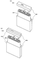
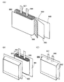
도 11의 (A)는 래미네이트형 이차 전지를 설명하는 도면이다. 도 11의 (B)는 래미네이트형 이차 전지를 설명하는 도면이다. 도 11의 (C)는 래미네이트형 이차 전지를 설명하는 도면이다.
도 12의 (A)는 래미네이트형 이차 전지를 설명하는 도면이다. 도 12의 (B)는 래미네이트형 이차 전지를 설명하는 도면이다.
도 13은 이차 전지의 외관을 나타낸 도면이다.
도 14는 이차 전지의 외관을 나타낸 도면이다.
도 15의 (A)는 이차 전지의 제작 방법을 설명하기 위한 도면이다. 도 15의 (B)는 이차 전지의 제작 방법을 설명하기 위한 도면이다. 도 15의 (C)는 이차 전지의 제작 방법을 설명하기 위한 도면이다.
도 16의 (A)는 휠 수 있는 이차 전지를 설명하는 도면이다. 도 16의 (B)는 휠 수 있는 이차 전지를 설명하는 도면이다. 도 16의 (C)는 휠 수 있는 이차 전지를 설명하는 도면이다. 도 16의 (D)는 휠 수 있는 이차 전지를 설명하는 도면이다. 도 16의 (E)는 휠 수 있는 이차 전지를 설명하는 도면이다.
도 17의 (A)는 휠 수 있는 이차 전지를 설명하는 도면이다. 도 17의 (B)는 휠 수 있는 이차 전지를 설명하는 도면이다.
도 18의 (A)는 전자 기기의 일례를 설명하는 도면이다. 도 18의 (B)는 전자 기기의 일례를 설명하는 도면이다. 도 18의 (C)는 이차 전지의 일례를 설명하는 도면이다. 도 18의 (D)는 전자 기기의 일례를 설명하는 도면이다. 도 18의 (E)는 이차 전지의 일례를 설명하는 도면이다. 도 18의 (F)는 전자 기기의 일례를 설명하는 도면이다. 도 18의 (G)는 전자 기기의 일례를 설명하는 도면이다. 도 18의 (H)는 전자 기기의 일례를 설명하는 도면이다.
도 19의 (A)는 전자 기기의 일례를 설명하는 도면이다. 도 19의 (B)는 전자 기기의 일례를 설명하는 도면이다. 도 19의 (C)는 전자 기기의 일례를 설명하는 도면이다.
도 20은 전자 기기의 일례를 설명하는 도면이다.
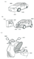
도 21의 (A)는 차량의 일례를 설명하는 도면이다. 도 21의 (B)는 차량의 일례를 설명하는 도면이다. 도 21의 (C)는 차량의 일례를 설명하는 도면이다.
도 22의 (A)는 전자 기기의 일례를 설명하는 도면이다. 도 22의 (B)는 전자 기기의 일례를 설명하는 도면이다. 도 22의 (C)는 전자 기기의 일례를 설명하는 도면이다.
도 23은 DSC를 나타낸 도면이다.
도 24는 DSC를 나타낸 도면이다.
도 25는 DSC를 나타낸 도면이다.
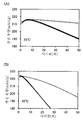
도 26의 (A)는 이차 전지의 사이클 특성을 나타낸 도면이다. 도 26의 (B)는 이차 전지의 사이클 특성을 나타낸 도면이다.
도 27의 (A)는 이차 전지의 사이클 특성을 나타낸 도면이다. 도 27의 (B)는 이차 전지의 사이클 특성을 나타낸 도면이다.1A is a view for explaining a method of manufacturing a substance. 1B is a view for explaining a method of manufacturing a material.
2A is a view for explaining a method of manufacturing a positive electrode active material. 2B is a view for explaining a method of manufacturing a positive electrode active material.
3 is a view for explaining a method of manufacturing a positive electrode active material.
4 is a view for explaining a method of manufacturing a positive electrode active material.
5A is a view for explaining a coin-type secondary battery. 5B is a view for explaining a coin-type secondary battery. 5C is a diagram for explaining charging of a secondary battery.
6A is a view for explaining a cylindrical secondary battery. 6B is a view for explaining a cylindrical secondary battery. 6C is a view for explaining a cylindrical secondary battery. 6D is a view for explaining a cylindrical secondary battery.
7A is a view for explaining an example of a secondary battery. 7B is a view for explaining an example of a secondary battery.
8A is a view for explaining an example of a secondary battery. 8B is a view for explaining an example of a secondary battery. 8C is a view for explaining an example of a secondary battery. 8D is a view for explaining an example of a secondary battery.
9A is a view for explaining an example of a secondary battery. 9B is a view for explaining an example of a secondary battery.
10 is a view for explaining an example of a secondary battery.
11A is a view for explaining a laminate type secondary battery. 11B is a view for explaining a laminate type secondary battery. 11C is a view for explaining a laminate type secondary battery.
12A is a view for explaining a laminate type secondary battery. 12B is a view for explaining a laminate type secondary battery.
13 is a view showing an external appearance of a secondary battery.
14 is a view showing an external appearance of a secondary battery.
15A is a view for explaining a method of manufacturing a secondary battery. 15B is a view for explaining a method of manufacturing a secondary battery. 15C is a view for explaining a method of manufacturing a secondary battery.
16A is a view for explaining a rechargeable battery that can be bent. FIG. 16B is a view for explaining a bendable secondary battery. FIG. 16C is a view for explaining a bendable secondary battery. FIG. 16D is a view for explaining a bendable secondary battery. FIG. 16E is a view for explaining a bendable secondary battery.
17A is a view for explaining a bendable secondary battery. 17B is a view for explaining a rechargeable battery that can be bent.
18A is a diagram for explaining an example of an electronic device. 18B is a diagram for explaining an example of an electronic device. 18C is a view for explaining an example of a secondary battery. 18D is a diagram for explaining an example of an electronic device. 18E is a view for explaining an example of a secondary battery. 18F is a diagram for explaining an example of an electronic device. 18G is a diagram for explaining an example of an electronic device. 18H is a diagram for explaining an example of an electronic device.
19A is a diagram for explaining an example of an electronic device. 19B is a diagram for explaining an example of an electronic device. 19C is a diagram for explaining an example of an electronic device.
It is a figure explaining an example of an electronic device.
21A is a view for explaining an example of a vehicle. 21B is a diagram for explaining an example of a vehicle. 21C is a view for explaining an example of a vehicle.
22A is a diagram for explaining an example of an electronic device. 22B is a diagram for explaining an example of an electronic device. 22C is a diagram for explaining an example of an electronic device.
23 is a diagram illustrating a DSC.
24 is a diagram illustrating a DSC.
25 is a diagram illustrating a DSC.
26A is a diagram illustrating cycle characteristics of a secondary battery. 26B is a diagram illustrating cycle characteristics of a secondary battery.
27A is a diagram illustrating cycle characteristics of a secondary battery. 27B is a diagram illustrating cycle characteristics of a secondary battery.
이하에서는, 본 발명의 실시형태에 대하여 도면을 사용하여 자세히 설명한다. 다만, 본 발명은 이하의 설명에 한정되지 않고, 그 형태 및 자세한 사항을 다양하게 변경할 수 있다는 것은 통상의 기술자라면 용이하게 이해할 수 있다. 또한 본 발명은 이하에 나타내는 실시형태의 기재 내용에 한정하여 해석되는 것은 아니다.EMBODIMENT OF THE INVENTION Hereinafter, embodiment of this invention is described in detail using drawing. However, the present invention is not limited to the following description, and it can be easily understood by those skilled in the art that the form and details can be variously changed. In addition, this invention is limited to the description of embodiment shown below and is not interpreted.
또한 본 명세서 등에서 결정면 및 방향은 밀러 지수(Miller index)로 나타낸다. 결정학에서 결정면 및 방향의 표기는 숫자 위에 바를 덧붙이지만, 본 명세서 등에서는 출원 표기의 제약상 숫자 위에 바를 덧붙이는 대신 숫자 앞에 -(마이너스 기호)를 덧붙여 표현하는 경우가 있다. 또한 결정 내의 방향을 나타내는 개별 방위는 []로, 등가의 방향 모두를 나타내는 집합 방위는 <>로, 결정면을 나타내는 개별면은 ()로, 등가의 대칭성을 가지는 집합면은 {}로 각각 표현한다.In addition, in the present specification and the like, the crystal plane and direction are represented by a Miller index. In crystallography, a bar is added to a number to indicate a crystal plane and a direction, but in this specification and the like, there are cases where a - (minus sign) is added in front of a number instead of adding a bar to the number due to restrictions on the notation of the application. In addition, individual orientations indicating directions within the crystal are represented by [], collective orientations representing all equivalent directions are represented by <>, individual planes representing crystal planes are represented by (), and aggregate planes with equivalent symmetry are represented by {}. .
본 명세서 등에서 편석(偏析)이란 복수의 원소(예를 들어 A, B, C)로 이루어지는 고체에서, 어느 원소(예를 들어 B)가 공간적으로 불균일하게 분포되는 현상을 말한다.In the present specification and the like, segregation refers to a phenomenon in which a certain element (eg, B) is spatially non-uniformly distributed in a solid composed of a plurality of elements (eg, A, B, and C).
본 명세서 등에서 활물질 등의 입자의 표층부란 표면으로부터 10nm 정도까지의 영역을 말한다. 금이나 크랙(crack)에 의하여 생긴 면도 표면이라고 하여도 좋다. 또한 표층부보다 깊은 영역을 내부라고 한다.In this specification and the like, the surface layer portion of particles such as an active material refers to a region from the surface to about 10 nm. It may also be referred to as a shaved surface caused by cracks or cracks. Also, the area deeper than the surface layer is called the inside.
본 명세서 등에서 리튬과 전이 금속을 포함한 복합 산화물이 가지는 층상 암염형 결정 구조란 양이온과 음이온이 교대로 배열된 암염형 이온 배열을 가지고 전이 금속과 리튬이 규칙적으로 배열되어 이차원 평면을 형성하기 때문에, 리튬의 이차원적인 확산이 가능한 결정 구조를 말한다. 또한 양이온 또는 음이온의 결손 등의 결함이 있어도 좋다. 또한 층상 암염형 결정 구조는, 엄밀하게 말하자면 암염형 결정의 격자가 변형된 구조를 가지는 경우가 있다.In the present specification, etc., the layered rock salt crystal structure of a composite oxide containing lithium and a transition metal has a rock salt type ion arrangement in which cations and anions are alternately arranged, and the transition metal and lithium are regularly arranged to form a two-dimensional plane, so lithium It refers to a crystal structure in which two-dimensional diffusion of Moreover, there may exist defects, such as a cation or an anion defect|deletion. Strictly speaking, the layered rock salt crystal structure may have a structure in which the lattice of the rock salt crystal is deformed.
또한 본 명세서 등에서 암염형 결정 구조란 양이온과 음이온이 교대로 배열된 구조를 말한다. 또한 양이온 또는 음이온의 결손이 있어도 좋다.In addition, in this specification, the rock salt crystal structure refers to a structure in which cations and anions are alternately arranged. Moreover, there may be a defect|deletion of a cation or an anion.
또한 본 명세서 등에서 리튬과 전이 금속을 포함한 복합 산화물이 가지는 의사 스피넬형 결정 구조란, 공간군 R-3m이고, 스피넬형 결정 구조가 아니지만 코발트, 마그네슘 등의 이온이 산소 6배위 위치를 차지하고, 양이온의 배열이 스피넬형과 비슷한 대칭성을 가지는 결정 구조를 말한다. 또한 의사 스피넬형 결정 구조에서는 리튬 등의 경원소는 산소 4배위 위치를 차지하는 경우가 있고, 이 경우에도 이온의 배열이 스피넬형과 비슷한 대칭성을 가진다.In addition, in the present specification, etc., the pseudo spinel crystal structure of the composite oxide containing lithium and transition metal is a space group R-3m, and although it is not a spinel crystal structure, ions such as cobalt and magnesium occupy the oxygen 6 coordination position, and the cation of It refers to a crystal structure whose arrangement has a symmetry similar to that of a spinel type. In addition, in the pseudo spinel crystal structure, a light element such as lithium occupies an oxygen tetracoordinate position in some cases, and even in this case, the arrangement of ions has a symmetry similar to that of the spinel type.
또한 의사 스피넬형 결정 구조는 층 간에 랜덤하게 Li을 가지지만 CdCl2형 결정 구조와 유사한 결정 구조라고도 할 수 있다. 이 CdCl2형과 유사한 결정 구조는, 니켈산 리튬을 충전 심도 0.94까지 충전하였을 때(Li0.06NiO2)의 결정 구조와 가깝지만, 순수한 코발트산 리튬, 또는 코발트를 많이 포함하는 층상 암염형 양극 활물질은 일반적으로 이러한 결정 구조를 취하지 않는 것으로 알려져 있다.In addition, although the pseudo spinel-type crystal structure has Li randomly between layers, it can also be referred to as a crystal structure similar to the CdCl 2 type crystal structure. The crystal structure similar to this CdCl 2 type is close to the crystal structure when lithium nickelate is charged to a charge depth of 0.94 (Li 0.06 NiO 2 ), but the layered rock salt type positive active material containing a lot of pure lithium cobaltate or cobalt is It is generally known that they do not adopt such a crystal structure.
층상 암염형 결정 및 암염형 결정의 음이온은 입방 최조밀 쌓임 구조(면심 입방 격자 구조)를 취한다. 의사 스피넬형 결정도 음이온은 입방 최조밀 쌓임 구조를 취한다고 추정된다. 이들이 접촉할 때 음이온으로 구성되는 입방 최조밀 쌓임 구조의 방향이 일치하는 결정면이 존재한다. 다만 층상 암염형 결정 및 의사 스피넬형 결정의 공간군은 R-3m이고, 암염형 결정의 공간군 Fm-3m(일반적인 암염형 결정의 공간군) 및 Fd-3m(가장 단순한 대칭성을 가지는 암염형 결정의 공간군)과는 다르기 때문에, 상기 조건을 만족시키는 결정면의 밀러 지수는 층상 암염형 결정 및 의사 스피넬형 결정과, 암염형 결정 사이에서 다르다. 본 명세서에서는 층상 암염형 결정, 의사 스피넬형 결정, 및 암염형 결정에서, 음이온으로 구성되는 입방 최조밀 쌓임 구조의 방향이 일치하는 상태를, 결정 배향이 실질적으로 일치한다고 하는 경우가 있다.Anions of the layered rock salt crystal and the rock salt crystal have a cubic most dense stacked structure (face-centered cubic lattice structure). It is presumed that the pseudo-spinel-type crystallinity anion adopts a cubic most densely stacked structure. When they come into contact, there is a crystal plane that coincides with the orientation of the cubic densest stacked structure composed of anions. However, the space group of the lamellar halite crystal and the pseudo spinel crystal is R-3m, and the space groups of the halite crystal are Fm-3m (the space group of a general halite crystal) and Fd-3m (the rock salt crystal having the simplest symmetry). space group of ), the Miller index of the crystal plane satisfying the above conditions is different between the layered rock salt crystal and pseudo spinel crystal, and the rock salt crystal. In the present specification, in the layered rock salt crystal, the pseudo spinel crystal, and the rock salt crystal, the state in which the directions of the cubic densest stacked structure composed of anions coincide may be said to substantially coincide with the crystal orientation.
2개의 영역의 결정 배향이 실질적으로 일치하는지는 TEM(transmission electron microscope) 이미지, STEM(scanning transmission electron microscope) 이미지, HAADF-STEM(high-angle annular dark-field scanning transmission electron microscope) 이미지, ABF-STEM(annular bright-field scanning transmission electron microscope) 이미지 등에서 판단할 수 있다. X선 회절(XRD), 전자 회절, 중성자 회절 등도 판단의 재료로 할 수 있다. TEM 이미지 등에서는 양이온과 음이온의 배열이 밝은 선과 어두운 선의 반복으로서 관찰될 수 있다. 층상 암염형 결정과 암염형 결정에서 입방 최조밀 쌓임 구조의 방향이 일치하면, 결정 간에서 밝은 선과 어두운 선의 반복이 이루는 각도가 5° 이하, 바람직하게는 2.5° 이하인 상태가 관찰될 수 있다. 또한 TEM 이미지 등에서 산소, 플루오린을 비롯한 경원소는 명확하게 관찰될 수 없는 경우가 있지만, 이러한 경우에는 금속 원소의 배열에 의하여 배향의 일치를 판단할 수 있다.A transmission electron microscope (TEM) image, a scanning transmission electron microscope (STEM) image, a high-angle annular dark-field scanning transmission electron microscope (HAADF-STEM) image, and ABF-STEM (annular bright-field scanning transmission electron microscope) image, etc. can be determined. X-ray diffraction (XRD), electron diffraction, neutron diffraction, etc. can be used as a material for judgment. In a TEM image, etc., the arrangement of cations and anions can be observed as a repetition of light and dark lines. If the direction of the cubic densest stacking structure in the layered halite crystal and the halite crystal is the same, it can be observed that the angle formed by the repetition of light and dark lines between crystals is 5° or less, preferably 2.5° or less. In addition, there are cases in which light elements such as oxygen and fluorine cannot be clearly observed in a TEM image, etc., but in this case, alignment of orientation can be judged by the arrangement of metal elements.
또한 본 명세서 등에서 양극 활물질의 이론 용량이란 양극 활물질이 가지는 삽입·이탈 가능한 리튬이 모두 이탈되었을 때의 전기량을 말한다. 예를 들어 LiCoO2의 이론 용량은 274mAh/g이고, LiNiO2의 이론 용량은 274mAh/g이고, LiMn2O4의 이론 용량은 148mAh/g이다.In addition, in this specification and the like, the theoretical capacity of the positive active material refers to the amount of electricity when all of the insertable/removable lithium of the positive active material is desorbed. For example, the theoretical capacity of LiCoO 2 is 274 mAh/g, the theoretical capacity of LiNiO 2 is 274 mAh/g, and the theoretical capacity of LiMn 2 O 4 is 148 mAh/g.
또한 본 명세서 등에서 삽입·이탈 가능한 리튬이 모두 삽입되었을 때의 충전 심도를 0으로 하고, 양극 활물질이 가지는 삽입·이탈 가능한 리튬이 모두 이탈되었을 때의 충전 심도를 1로 한다.In this specification, etc., the charging depth when all insertable/removable lithium is inserted is set to 0, and the charging depth when all insertable/removable lithium included in the positive electrode active material is detached is set to 1.
또한 본 명세서 등에 있어서 충전이란, 전지 내에서 양극으로부터 음극으로 리튬 이온을 이동시키고, 외부 회로에서 양극으로부터 음극으로 전자를 이동시키는 것을 말한다. 양극 활물질에 대해서는 리튬 이온을 이탈시키는 것을 충전이라고 한다. 또한 충전 심도가 0.7 이상 0.9 이하인 양극 활물질을 고전압으로 충전된 양극 활물질이라고 부르는 경우가 있다.In addition, in this specification and the like, charging means moving lithium ions from the positive electrode to the negative electrode in the battery and moving electrons from the positive electrode to the negative electrode in an external circuit. For the cathode active material, the release of lithium ions is called charging. Also, a positive electrode active material having a charge depth of 0.7 or more and 0.9 or less is sometimes referred to as a positive electrode active material charged with a high voltage.
마찬가지로 방전이란, 전지 내에서 음극으로부터 양극으로 리튬 이온을 이동시키고, 외부 회로에서 음극으로부터 양극으로 전자를 이동시키는 것을 말한다. 양극 활물질에 대해서는 리튬 이온을 삽입하는 것을 방전이라고 한다. 또한 충전 심도가 0.06 이하의 양극 활물질, 또는 고전압으로 충전된 상태로부터 충전 용량의 90% 이상의 용량이 방전된 양극 활물질을 충분히 방전된 양극 활물질이라고 한다.Similarly, discharging refers to the movement of lithium ions from the negative electrode to the positive electrode in the battery and the movement of electrons from the negative electrode to the positive electrode in an external circuit. The insertion of lithium ions into the cathode active material is called discharging. In addition, a positive active material having a charge depth of 0.06 or less, or a positive active material in which 90% or more of the charge capacity is discharged from a state of being charged at a high voltage, is referred to as a sufficiently discharged positive active material.
또한 본 명세서 등에서 불균형한 상변화란 물리량의 비선형 변화가 일어나는 현상을 말한다. 예를 들어 용량(Q)을 전압(V)으로 미분(dQ/dV)함으로써 얻어지는 dQ/dV 곡선에서의 피크 주변에서는 불균형한 상변화가 일어나 결정 구조가 크게 변화되는 것으로 생각된다.In addition, in the present specification, an unbalanced phase change refers to a phenomenon in which a nonlinear change of a physical quantity occurs. For example, it is considered that an unbalanced phase change occurs around a peak in a dQ/dV curve obtained by differentiating (dQ/dV) of the capacitance (Q) with the voltage (V), thereby significantly changing the crystal structure.
이차 전지는 예를 들어 양극 및 음극을 가진다. 양극을 구성하는 재료로서 양극 활물질이 있다. 양극 활물질은 예를 들어 충방전 용량에 기여하는 반응을 일으키는 물질이다. 또한 양극 활물질은 그 일부에 충방전 용량에 기여하지 않는 물질을 포함하여도 좋다.A secondary battery has, for example, a positive electrode and a negative electrode. As a material constituting the positive electrode, there is a positive electrode active material. The positive electrode active material is, for example, a material that causes a reaction that contributes to the charge/discharge capacity. In addition, the positive electrode active material may contain a material that does not contribute to the charge/discharge capacity in a part thereof.
본 명세서 등에서, 본 발명의 일 형태의 양극 활물질은 양극 재료 또는 이차 전지용 양극재 등이라고 표현되는 경우가 있다. 또한 본 명세서 등에서, 본 발명의 일 형태의 양극 활물질은 화합물을 가지는 것이 바람직하다. 또한 본 명세서 등에서, 본 발명의 일 형태의 양극 활물질은 조성물을 가지는 것이 바람직하다. 또한 본 명세서 등에서, 본 발명의 일 형태의 양극 활물질은 복합체를 가지는 것이 바람직하다.In this specification and the like, the positive electrode active material of one embodiment of the present invention may be expressed as a positive electrode material or a positive electrode material for secondary batteries. In addition, in this specification and the like, it is preferable that the positive electrode active material of one embodiment of the present invention has a compound. In addition, in this specification and the like, it is preferable that the positive electrode active material of one embodiment of the present invention has a composition. In addition, in this specification and the like, it is preferable that the positive electrode active material of one embodiment of the present invention has a composite.
방전 레이트란, 전지 용량에 대한 방전 시의 전류의 상대적인 비율이고, 단위 C로 나타내어진다. 정격 용량 X(Ah)의 전지에서 1C 상당의 전류는 X(A)이다. 2X(A)의 전류로 방전시킨 경우에는 2C로 방전시켰다고 하고, X/5(A)의 전류로 방전시킨 경우에는 0.2C로 방전시켰다고 한다. 또한 충전 레이트도 마찬가지이고, 2X(A)의 전류로 충전시킨 경우에는 2C로 충전시켰다고 하고, X/5(A)의 전류로 충전시킨 경우에는 0.2C로 충전시켰다고 한다.The discharge rate is a relative ratio of the current at the time of discharging to the battery capacity, and is expressed in unit C. In a battery of rated capacity X(Ah), the current equivalent to 1C is X(A). When it is discharged with a current of 2X(A), it is said that it is discharged at 2C, and when it is discharged with a current of X/5(A), it is said that it is discharged at 0.2C. In addition, the charging rate is also the same, and when it is charged with a current of 2X(A), it is said that it is charged at 2C, and when it is charged with a current of X/5(A), it is said that it is charged at 0.2C.
정전류 충전이란, 예를 들어 충전 레이트를 일정하게 하여 충전을 하는 방법을 가리킨다. 정전압 충전이란, 예를 들어 충전이 상한 전압에 도달하였을 때, 전압을 일정하게 하여 충전을 하는 방법을 가리킨다. 정전류 방전이란, 예를 들어 방전 레이트를 일정하게 하여 방전을 하는 방법을 가리킨다.Constant current charging refers to, for example, a method of charging with a constant charging rate. Constant voltage charging refers to a method of charging with a constant voltage, for example, when charging reaches an upper limit voltage. A constant current discharge refers to the method of making a discharge rate constant and performing discharge, for example.
(실시형태 1)(Embodiment 1)
본 실시형태에서는 본 발명의 일 형태의 양극 활물질과, 그 제작 방법에 대하여 설명한다.In this embodiment, the positive electrode active material of one Embodiment of this invention and its manufacturing method are demonstrated.
본 발명의 일 형태의 양극 활물질은 금속 A, 전이 금속 Mt, 원소 X, 금속 M(2), 및 산소를 가진다. 또한 본 발명의 일 형태의 양극 활물질은 금속 M(1)을 가져도 좋다.The positive electrode active material of one embodiment of the present invention has a metal A, a transition metal Mt, an element X, a metal M(2), and oxygen. In addition, the positive electrode active material of one embodiment of the present invention may include the metal M(1).
금속 A는 알칼리 금속이다. 또는 금속 A로서 알칼리 토금속을 사용하여도 좋다.Metal A is an alkali metal. Alternatively, an alkaline earth metal may be used as the metal A.
전이 금속 Mt는 예를 들어 코발트, 망가니즈, 니켈, 및 철 중 하나 이상인 것이 바람직하다.The transition metal Mt is, for example, preferably at least one of cobalt, manganese, nickel, and iron.
원소 X는 예를 들어 마그네슘, 칼슘, 지르코늄, 란타넘, 및 바륨 중에서 선택되는 하나 이상이다.Element X is, for example, at least one selected from magnesium, calcium, zirconium, lanthanum, and barium.
본 발명의 일 형태의 양극 활물질이 원소 X를 가짐으로써, 본 발명의 일 형태의 양극 활물질을 사용한 이차 전지에 있어서, 예를 들어 충전 전압이 높은 경우에도 양극 활물질의 구조 안정성을 높일 수 있다. 충전 전압을 높임으로써 방전 용량 및 에너지 밀도를 높일 수 있다. 또한 구조 안정성이 높아지면 사이클 특성 등을 향상시킬 수 있다.When the positive electrode active material of one embodiment of the present invention has element X, in a secondary battery using the positive electrode active material of one embodiment of the present invention, the structural stability of the positive electrode active material can be improved even when, for example, the charging voltage is high. By increasing the charging voltage, it is possible to increase the discharge capacity and the energy density. In addition, when structural stability is increased, cycle characteristics and the like can be improved.
금속 M(2)는 예를 들어 니켈, 알루미늄, 망가니즈, 타이타늄, 바나듐, 철, 및 크로뮴 중에서 선택되는 하나 이상이고, 특히 니켈 및 알루미늄 중 하나 이상인 것이 바람직하고, 알루미늄인 것이 더 바람직하다. 금속 M(1)은 예를 들어 니켈, 알루미늄, 망가니즈, 타이타늄, 바나듐, 철, 및 크로뮴 중에서 선택되는 하나 이상이고 또한 금속 M(2)과 다른 금속인 것이 바람직하다.The metal M(2) is, for example, at least one selected from nickel, aluminum, manganese, titanium, vanadium, iron, and chromium, particularly preferably at least one of nickel and aluminum, and more preferably aluminum. The metal M(1) is, for example, at least one selected from nickel, aluminum, manganese, titanium, vanadium, iron, and chromium, and is preferably a metal different from the metal M(2).
전이 금속 Mt는 금속 M(2)와 다른 금속인 것이 바람직하다. 또한 전이 금속 Mt는 금속 M(1) 및 금속 M(2)와 다른 금속인 것이 더 바람직하다.The transition metal Mt is preferably a metal different from the metal M(2). It is also more preferable that the transition metal Mt is a metal different from the metals M(1) and M(2).
본 발명의 일 형태의 양극 활물질이 원소 X에 더하여 금속 M(2)를 가짐으로써, 본 발명의 일 형태의 양극 활물질을 사용한 이차 전지에 있어서 예를 들어 안전성이 높아지는 경우가 있다. 또한 높은 충전 전압에서 양극 활물질의 구조 안정성을 더 높일 수 있는 경우가 있다. 또한 충전 전압을 더 높일 수 있는 경우가 있다.When the positive electrode active material of one embodiment of the present invention has the metal M(2) in addition to the element X, for example, safety may increase in a secondary battery using the positive electrode active material of one embodiment of the present invention. In addition, there are cases in which the structural stability of the positive electrode active material can be further improved at a high charging voltage. There are also cases where the charging voltage can be further increased.
본 발명의 일 형태의 양극 활물질이 원소 X 및 금속 M(2)에 더하여 금속 M(1)을 가짐으로써, 본 발명의 일 형태의 양극 활물질을 사용한 이차 전지에 있어서, 예를 들어 충전 전압이 높은 경우에 양극 활물질의 구조 안정성을 더 높일 수 있는 경우가 있다. 또한 방전 용량이 더 증대하는 경우가 있다.Since the positive electrode active material of one embodiment of the present invention has a metal M(1) in addition to the element X and the metal M(2), in a secondary battery using the positive electrode active material of one embodiment of the present invention, for example, the charging voltage is high In some cases, the structural stability of the positive electrode active material may be further improved. Also, there are cases where the discharge capacity further increases.
<양극 활물질의 제작 방법 1><
이하에서 본 발명의 일 형태의 양극 활물질의 제작 방법에 대하여 도 1의 (A) 및 (B)를 사용하여 설명한다.Hereinafter, a method of manufacturing a positive electrode active material of one embodiment of the present invention will be described with reference to FIGS. 1A and 1B .
도 1의 (A)에 나타낸 제작 흐름에서는, 금속 A 및 전이 금속 Mt를 가지는 금속 산화물(이하, 금속 산화물(95))과 복수의 물질(이하, 물질(91), 물질(92), 물질(93), 및 물질(94))을 혼합하고, 어닐을 수행하여(단계 S34), 양극 활물질(100)을 얻는다(단계 S36). 여기서는 복수의 물질로서 4개의 물질을 예시하였지만, 복수의 물질은 3개 이하이어도 좋고 5개 이상이어도 좋다. 예를 들어 복수의 물질은 물질(91), 물질(92), 및 물질(94)의 3개이어도 좋다.In the manufacturing flow shown in FIG. 1A, a metal oxide (hereinafter, metal oxide 95) having a metal A and a transition metal Mt and a plurality of substances (hereinafter, a substance 91, a substance 92, a substance ( 93), and the material 94) are mixed, and annealing is performed (step S34) to obtain the positive electrode active material 100 (step S36). Here, four substances are exemplified as the plurality of substances, but the number of the plurality of substances may be three or less or five or more. For example, the plurality of substances may be three of a substance 91 , a substance 92 , and a substance 94 .
도 1의 (B)에 나타낸 제작 흐름에서는, 물질(91) 내지 물질(94)을 준비하고, 단계 S12에서 혼합 및 분쇄를 수행하여 혼합물(902)을 제작하고(단계 S14), 혼합물(902)과 금속 산화물(95)을 혼합하고, 어닐을 수행하여(단계 34), 양극 활물질(100)을 얻는다(단계 S36).In the manufacturing flow shown in FIG. 1B, materials 91 to 94 are prepared, and mixing and grinding are performed in step S12 to produce a mixture 902 (step S14), and a mixture 902. and the metal oxide 95 are mixed, and annealing is performed (step 34) to obtain the positive electrode active material 100 (step S36).
물질(91) 내지 물질(94)을 미리 분쇄함으로써, 단계 S34의 어닐 공정에서 금속 산화물(95)의 표면에 물질(91) 내지 물질(94)이 부착되기 쉬운 경우가 있다. 또한 금속 산화물(95)과 물질(91) 내지 물질(94)의 접촉 면적이 증대하는 경우가 있다. 따라서, 금속 산화물(95)에 물질(91) 내지 물질(94)이 가지는 원소 중 하나 이상을 첨가하기 쉬워지는 경우가 있다.By pre-pulverizing the materials 91 to 94, the materials 91 to 94 are likely to adhere to the surface of the metal oxide 95 in the annealing process of step S34 in some cases. In addition, the contact area between the metal oxide 95 and the substances 91 to 94 may increase. Accordingly, there is a case where it becomes easy to add one or more of the elements of the material 91 to the material 94 to the metal oxide 95 .
또한 도 1의 (B)에서는 물질(91) 내지 물질(94)과 함께 용매를 준비하고 습식으로 혼합을 수행하는 예를 나타내었지만, 건식으로 혼합을 수행하는 경우에는 용매를 준비하지 않아도 된다.In addition, in FIG. 1B , an example in which a solvent is prepared together with the materials 91 to 94 and mixing is performed in a wet manner is shown, but in the case of performing the mixing in a dry method, there is no need to prepare a solvent.
금속 산화물(95)은 입자인 것이 바람직하다.The metal oxide 95 is preferably particles.
또는 금속 산화물(95)은 CVD(Chemical vapor deposition)법, 스퍼터링법, 증착법 등을 사용하여 형성되는 박막이어도 좋다. 박막은 예를 들어 기판 위에 형성된다. 기판으로서는 예를 들어, 후술하는 집전체에 사용할 수 있는 재료의 박(箔)이나, 유리 기판, 수지 기판 등 다양한 형태의 기판을 사용할 수 있다.Alternatively, the metal oxide 95 may be a thin film formed using a chemical vapor deposition (CVD) method, a sputtering method, a vapor deposition method, or the like. A thin film is formed, for example, on a substrate. As a board|substrate, various types of board|substrates, such as foil of a material which can be used for the electrical power collector mentioned later, a glass substrate, and a resin board|substrate, can be used, for example.
금속 산화물(95)로서 예를 들어, 층상 암염형 결정 구조를 가지는 산화물을 사용할 수 있다. 또는 예를 들어 스피넬형 결정 구조를 가지는 산화물을 사용할 수 있다. 또는 예를 들어 금속 산화물(95)로서 인산 화합물, 규산 화합물 등을 사용하여도 좋다.As the metal oxide 95, for example, an oxide having a layered rock salt crystal structure can be used. Or, for example, an oxide having a spinel crystal structure may be used. Alternatively, for example, a phosphoric acid compound, a silicic acid compound, or the like may be used as the metal oxide 95 .
금속 산화물(95)이 층상 암염형 결정 구조를 가지는 산화물인 경우에는, 전이 금속 Mt로서 예를 들어 코발트, 망가니즈, 니켈, 알루미늄 등을 사용하면 좋다. 이러한 전이 금속 Mt를 가지는 재료로서는 예를 들어 코발트산 리튬, 망가니즈산 리튬, 니켈산 리튬, 코발트의 일부가 망가니즈로 치환된 코발트산 리튬, 코발트의 일부가 니켈로 치환된 코발트산 리튬, 또는 니켈-망가니즈-코발트산 리튬을 들 수 있다.When the metal oxide 95 is an oxide having a layered rock salt crystal structure, for example, cobalt, manganese, nickel, aluminum or the like may be used as the transition metal Mt. Examples of the material having such a transition metal Mt include lithium cobaltate, lithium manganate, lithium nickelate, lithium cobalt in which a part of cobalt is substituted with manganese, lithium cobalt in which part of cobalt is substituted with nickel, or and nickel-manganese-lithium cobaltate.
금속 산화물(95)로서 예를 들어 공간군 R-3m으로 나타내어지는 구조를 가지는 산화물을 사용하면 좋다.As the metal oxide 95, for example, an oxide having a structure represented by the space group R-3m may be used.
금속 산화물(95)이 스피넬형 결정 구조를 가지는 산화물인 경우에는, 전이 금속 Mt로서 예를 들어 망가니즈, 니켈 등을 사용하면 좋다.When the metal oxide 95 is an oxide having a spinel crystal structure, for example, manganese, nickel, or the like may be used as the transition metal Mt.
물질(91) 내지 물질(94)이 가지는 원소의 일부는 상기 혼합 및 어닐에 의하여 금속 산화물(95)의 표면 및 표면 근방의 영역, 또는 내부에 첨가되는 것이 바람직하다. 또한 상기 혼합 및 어닐에 의하여, 금속 산화물(95)이 가지는 원소의 일부가, 물질(91) 내지 물질(94)이 가지는 원소의 일부와 치환되는 경우가 있다.A part of the elements of the materials 91 to 94 is preferably added to the surface and a region near the surface of the metal oxide 95 by the mixing and annealing, or to the inside. In addition, by the mixing and annealing, a part of the element included in the metal oxide 95 may be substituted with a part of the element included in the materials 91 to 94 .
물질(91) 내지 물질(94)이 가지는 원소의 일부가 금속 산화물(95)에 첨가됨으로써, 본 발명의 일 형태의 양극 활물질을 사용한 이차 전지에 있어서 예를 들어 용량 향상, 에너지 밀도 향상, 사이클 특성 향상, 신뢰성 향상, 또는 안전성 향상 등을 실현할 수 있다.When a part of the elements of the substances 91 to 94 are added to the metal oxide 95, for example, capacity improvement, energy density improvement, and cycle characteristics in a secondary battery using the positive electrode active material of one embodiment of the present invention. improvement, reliability improvement, safety improvement, or the like can be realized.
물질(91)로서, 금속 A를 가지는 할로젠 화합물을 사용할 수 있다.As the material 91, a halogen compound having metal A can be used.
금속 A로서 리튬을 사용하는 경우, 물질(91)로서는 예를 들어 플루오린화 리튬, 염화 리튬 등을 사용할 수 있다. 특히 플루오린화 리튬은 후술하는 어닐 공정에서 용융되기 쉽기 때문에 바람직하다. 금속 A로서 소듐을 사용하는 경우, 물질(91)로서는 예를 들어 플루오린화 소듐, 염화 소듐 등을 사용할 수 있다. 금속 A로서 포타슘을 사용하는 경우, 물질(91)로서는 예를 들어 플루오린화 포타슘 등을 사용할 수 있다. 금속 A로서 칼슘을 사용하는 경우, 물질(91)로서는 예를 들어 염화 칼슘 등을 사용할 수 있다.When lithium is used as the metal A, as the material 91, for example, lithium fluoride, lithium chloride, or the like can be used. In particular, lithium fluoride is preferable because it is easy to melt in the annealing step described later. When sodium is used as the metal A, for example, sodium fluoride, sodium chloride, or the like can be used as the material 91 . When potassium is used as the metal A, for example, potassium fluoride or the like can be used as the material 91 . When calcium is used as the metal A, as the substance 91, for example, calcium chloride or the like can be used.
물질(92)은 원소 X를 가지는 화합물이다.Substance 92 is a compound having element X.
원소 X로서 마그네슘을 사용하는 경우, 물질(92)로서는 예를 들어 플루오린화 마그네슘, 산화 마그네슘, 수산화 마그네슘, 탄산 마그네슘, 염화 마그네슘 등을 사용할 수 있다.When magnesium is used as the element X, magnesium fluoride, magnesium oxide, magnesium hydroxide, magnesium carbonate, magnesium chloride, or the like can be used as the material 92, for example.
상술한 원소 X를 가지는 화합물과 금속 A를 가지는 할로젠 화합물의 혼합물에 대하여 어닐을 수행함으로써 공융 반응이 일어나, 원소 X를 가지는 화합물의 융점보다 낮은 온도에서 상기 혼합물의 적어도 일부의 영역에서 용융을 일으킬 수 있다.By performing annealing on the mixture of the compound having the element X and the halogen compound having the metal A, a eutectic reaction occurs, causing melting in at least a part of the mixture at a temperature lower than the melting point of the compound having the element X. can
원소 X가 양극 활물질의 충방전 반응에 기여하지 않는 원소인 경우에는, 그 첨가량을 지나치게 증가하면, 얻어지는 방전 용량이 현저히 저하될 우려가 있다. 본 발명의 일 형태의 양극 활물질의 제작 방법을 사용함으로써, 금속 산화물(95)에서 표면 및 표면 근방의 원소 X의 농도를 내부의 농도보다 높게 할 수 있다. 금속 산화물(95)에서 원소 X의 농도 구배를 일으키고 표면 및 표면 근방의 농도를 더 높임으로써, 양극 활물질 전체에 첨가되는 원소 X의 양이 적어도 효과를 효율적으로 얻을 수 있는 경우가 있다.In the case where the element X is an element that does not contribute to the charge/discharge reaction of the positive electrode active material, if the amount added is excessively increased, there is a fear that the obtained discharge capacity may significantly decrease. By using the manufacturing method of the positive electrode active material of one embodiment of the present invention, the concentration of the element X on the surface and in the vicinity of the surface of the metal oxide 95 can be made higher than the concentration inside. By generating a concentration gradient of element X in the metal oxide 95 and further increasing the concentration on the surface and in the vicinity of the surface, the effect can be efficiently obtained at least in the amount of element X added to the entire positive electrode active material in some cases.
예를 들어, 표면으로부터의 거리가 20nm 이상 200nm 이하인 제 1 영역에서의 원소 X의 원자수(Ax1)와 전이 금속 Mt의 원자수(Am1)의 비율의 값{(Ax1)/(Am1)}은 표면으로부터의 거리가 1μm 이상 3μm 이하인 제 2 영역에서의 원소 X의 원자수(Ax2)와 전이 금속 Mt의 원자수(Am2)의 비율의 값{(Ax2)/(Am2)}보다 높다.For example, the value {(Ax1)/(Am1)} of the ratio of the number of atoms of element X (Ax1) to the number of atoms of transition metal Mt (Am1) in the first region where the distance from the surface is 20 nm or more and 200 nm or less is {(Ax1)/(Am1)} It is higher than the value {(Ax2)/(Am2)} of the ratio of the number of atoms (Ax2) of the element X to the number of atoms (Am2) of the transition metal Mt in the second region having a distance from the surface of 1 µm or more and 3 µm or less.
물질(91)과 물질(92)을 혼합하고 어닐을 수행함으로써 공융 반응이 일어나는 것이 바람직하다. 또는 공융점이 저하되는 것이 바람직하다. 또는 공융 결정화 반응(eutectic crystallization reaction)이 일어나는 것이 바람직하다. 또는 공융 결정화점이 저하되는 것이 바람직하다. 이하, 물질(91)과 물질(92)의 공융 반응에 대하여 설명하는 경우에는, 그 기재를 공융점의 저하, 공융 결정화 반응, 공융 결정화점의 저하에 적용시켜도 좋다.Preferably, the eutectic reaction occurs by mixing the material 91 and the material 92 and performing an annealing. Alternatively, it is preferable that the eutectic point is lowered. Alternatively, it is preferable that a eutectic crystallization reaction occurs. Alternatively, the eutectic crystallization point is preferably lowered. Hereinafter, when the eutectic reaction of the substance 91 and the substance 92 is described, the description may be applied to lowering of the eutectic point, the eutectic crystallization reaction, and the lowering of the eutectic crystallization point.
물질(91)과 물질(92)을 혼합하고 어닐을 수행하는 경우, 물질(91)과 물질(92) 사이에 공융 반응이 일어남으로써, 물질(91)과 물질(92)의 융점보다 낮은 온도에서 물질(91)과 물질(92)의 혼합물의 용융이 일어나, 물질(91)과 물질(92)이 가지는 원소 중 하나 이상이 금속 산화물(95)에 첨가되기 쉬워진다.When the material 91 and the material 92 are mixed and annealing is performed, a eutectic reaction occurs between the material 91 and the material 92, so that at a temperature lower than the melting point of the material 91 and the material 92 . Melting of the mixture of the material 91 and the material 92 occurs, so that at least one of the elements of the material 91 and the material 92 is likely to be added to the metal oxide 95 .
물질(93)은 금속 M(1)을 가지는 화합물이다. 물질(94)은 금속 M(2)를 가지는 화합물이다. 물질(93) 및 물질(94)은 본 발명의 일 형태의 양극 활물질의 제작에 있어서 금속원으로서 기능하는 것이 바람직하다.Substance 93 is a compound having metal M(1). Material 94 is a compound having metal M(2). The material 93 and the material 94 preferably function as a metal source in the production of the positive electrode active material of one embodiment of the present invention.
금속 산화물(95)에서 금속 M(2)의 농도 구배를 일으키고 표면 및 표면 근방의 농도를 더 높임으로써, 양극 활물질 전체에 첨가되는 금속 M(2)의 양이 적어도 효과를 효율적으로 얻을 수 있는 경우가 있다.By causing a concentration gradient of the metal M(2) in the metal oxide 95 and increasing the concentration on the surface and near the surface further, the amount of the metal M(2) added to the entire positive electrode active material is at least effective when there is
예를 들어, 표면으로부터의 거리가 20nm 이상 200nm 이하인 제 1 영역에서의 금속 M(2)의 원자수(Amb1)와 전이 금속 Mt의 원자수(Am1)의 비율의 값{(Amb1)/(Am1)}은 표면으로부터의 거리가 1μm 이상 3μm 이하인 제 2 영역에서의 원소 X의 원자수(Amb2)와 전이 금속 Mt의 원자수(Am2)의 비율의 값{(Amb2)/(Am2)}보다 높다.For example, the value {(Amb1)/(Am1) of the ratio of the number of atoms (Amb1) of the metal M(2) to the number of atoms (Am1) of the transition metal Mt in the first region where the distance from the surface is 20 nm or more and 200 nm or less )} is higher than the value {(Amb2)/(Am2)} of the ratio of the number of atoms of element X (Amb2) to the number of atoms of transition metal Mt (Am2) in the second region where the distance from the surface is 1 μm or more and 3 μm or less .
물질(93) 및 물질(94) 중 한쪽 또는 양쪽이 물질(91)과 물질(92)의 공융 반응을 현저히 저해하는 경우에는, 도 2의 (A) 및 (B)에 나타낸 바와 같이 어닐을 두 번으로 나누어도 좋다. 더 구체적으로는, 공융 반응을 저해하는 물질 외의 물질을 혼합하고, 어닐을 수행하고(단계 S34), 물질(91) 및 물질(92) 중 적어도 한쪽이 가지는 원소 중 하나 이상을 금속 산화물(95)에 첨가한 후에, 공융 반응을 저해하는 물질을 첨가하여 혼합하고, 어닐을 수행하여(단계 S55), 양극 활물질(100)을 얻는다(단계 S36).When one or both of the material 93 and the material 94 significantly inhibits the eutectic reaction of the material 91 and the material 92, as shown in (A) and (B) of FIG. It may be divided into times. More specifically, a material other than the material inhibiting the eutectic reaction is mixed, annealing is performed (step S34), and at least one of the elements of the material 91 and the material 92 is added to the metal oxide 95. After addition, a material that inhibits the eutectic reaction is added and mixed, and annealing is performed (step S55) to obtain the positive electrode active material 100 (step S36).
도 2의 (A)에서는 물질(91), 물질(92), 및 금속 산화물(95)을 혼합하고, 어닐을 수행하고(단계 S34), 물질(93), 물질(94), 및 어닐링된 혼합물을 혼합하고, 어닐을 수행하여(단계 S55), 양극 활물질(100)을 얻는다(단계 S36). 도 2의 (B)에서는 물질(91), 물질(92), 물질(93), 및 금속 산화물(95)을 혼합하고, 어닐을 수행하고(단계 S34), 물질(94) 및 어닐링된 혼합물을 혼합하고, 어닐을 수행하여(단계 S55), 양극 활물질(100)을 얻는다(단계 S36).In FIG. 2A , the material 91 , the material 92 , and the metal oxide 95 are mixed, annealing is performed (step S34 ), the material 93 , the material 94 , and the annealed mixture are mixed and annealed (step S55) to obtain the positive electrode active material 100 (step S36). In FIG. 2B, the material 91, the material 92, the material 93, and the metal oxide 95 are mixed, annealing is performed (step S34), and the material 94 and the annealed mixture are mixed. The mixture is mixed and annealed (step S55) to obtain the positive electrode active material 100 (step S36).
예를 들어 물질(94)로 인한 공융 반응의 저해가 현저한 경우에는 도 2의 (A) 또는 (B)의 공정을 사용하면 좋다. 또한 예를 들어 물질(93) 및 물질(94)의 양쪽이 공융 반응을 현저히 저해하는 경우에는 도 2의 (A)의 공정을 사용하면 좋다.For example, when the inhibition of the eutectic reaction due to the substance 94 is significant, the process of FIG. 2 (A) or (B) may be used. Also, for example, when both the substance 93 and the substance 94 significantly inhibit the eutectic reaction, the process of FIG. 2A may be used.
어닐을 두 번 수행하면, 생산성이 저하되고 비용의 상승을 초래하기 때문에, 도 1의 (A)에 나타낸 바와 같이 어닐 공정을 한 번 수행하는 것이 바람직하다. 따라서, 물질(93) 및 물질(94)은 물질(91)과 물질(92)의 공융 반응을 가능한 한 저해하지 않는 것이 바람직하다. 더 구체적으로는 예를 들어 물질(93) 및 물질(94)은 물질(91)과 물질(92)의 공융 반응이 일어나는 온도보다 낮은 온도에서 안정성이 높은 것이 바람직하다. 예를 들어, 상기 공융 반응이 일어나는 온도보다 낮은 온도에서 원소 X와의 반응성이 낮은 것이 바람직하다.If the annealing is performed twice, it is preferable to perform the annealing process once as shown in FIG. Accordingly, it is preferred that the materials 93 and 94 do not inhibit the eutectic reaction of the materials 91 and 92 as much as possible. More specifically, for example, it is preferable that the material 93 and the material 94 have high stability at a temperature lower than the temperature at which the eutectic reaction of the material 91 and the material 92 occurs. For example, it is preferable that the reactivity with element X is low at a temperature lower than the temperature at which the eutectic reaction occurs.
한편, 물질(93) 및 물질(94)은 안정성이 지나치게 높으면, 어닐 공정에서 금속 산화물(95)에 첨가되기 어려운 경우가 있다. 따라서, 물질(93) 및 물질(94)의 융점은 어닐 공정의 온도보다 지나치게 높지 않은 것이 바람직하다. 예를 들어, 물질(93) 및 물질(94)의 융점이 어닐 공정의 온도보다 높은 경우에는, 어닐 공정의 온도와 융점의 차이는 바람직하게는 500℃ 이하, 더 바람직하게는 400℃ 이하, 더욱 바람직하게는 300℃ 이하이다. 또한 물질(91)과 물질(92)에 더하여 물질(93) 및 물질(94) 중 어느 한쪽 또는 양쪽이 공융 반응을 일으켜도 좋다.On the other hand, if the stability of the material 93 and the material 94 is too high, it may be difficult to be added to the metal oxide 95 in the annealing process. Accordingly, it is preferred that the melting points of materials 93 and 94 are not too high above the temperature of the annealing process. For example, when the melting points of the material 93 and the material 94 are higher than the temperature of the annealing process, the difference between the temperature and the melting point of the annealing process is preferably 500° C. or less, more preferably 400° C. or less, further Preferably it is 300 degrees C or less. In addition to the material 91 and the material 92 , either or both of the material 93 and the material 94 may cause a eutectic reaction.
공융 반응은 예를 들어 DSC(시차 주사 열량 측정: Differential scanning calorimetry)를 사용하여 평가할 수 있다.The eutectic reaction can be evaluated using, for example, DSC (Differential Scanning Calorimetry).
<DSC><DSC>
DSC에서는 측정 온도를 주사하고 열량의 변화를 관측한다. 이 열량의 변화는 예를 들어 융해 등의 흡열 반응이나, 결정화 등의 발열 반응에 의하여 일어난다.In DSC, the measured temperature is scanned and the change in calorific value is observed. This change in the amount of heat is caused by, for example, an endothermic reaction such as melting or an exothermic reaction such as crystallization.
물질(91)과 물질(92) 사이에 공융 반응이 일어나면, 반응 온도 및 그 근방에서 예를 들어 흡열 반응을 시사하는 열량의 변화가 관측된다.When a eutectic reaction occurs between the material 91 and the material 92, a change in the amount of heat indicative of, for example, an endothermic reaction is observed at and in the vicinity of the reaction temperature.
이하에서, 원소 X로서 마그네슘을 사용하고 금속 M(2)로서 알루미늄을 사용하는 경우의 물질(91), 물질(92), 및 물질(94)의 일례와 DSC에 의한 평가 결과를 도 23, 도 24, 및 도 25에 나타낸다. 도 23, 도 24, 및 도 25의 가로축은 온도(Temperature)를 나타내고 세로축은 열류(Heat Flow)를 나타낸다.In the following, examples of the material 91, the material 92, and the material 94 in the case of using magnesium as the element X and aluminum as the metal M(2) and the evaluation results by DSC are shown in Figs. 24 and Fig. 25 . 23, 24, and 25, the horizontal axis represents the temperature (Temperature) and the vertical axis represents the heat flow (Heat Flow).
도 23에는 물질(91)과 물질(92)의 혼합물의 DSC의 일례를 나타내었다. 여기서는 물질(91)로서 플루오린화 리튬을 사용하고, 물질(92)로서 플루오린화 마그네슘을 사용한다.23 shows an example of a DSC of a mixture of material 91 and material 92 . Here, lithium fluoride is used as the material 91 and magnesium fluoride is used as the material 92 .
도 24에는 물질(91), 물질(92), 및 물질(94)의 혼합물의 DSC의 일례를 나타내었다. 여기서는 물질(91)로서 플루오린화 리튬을 사용하고, 물질(92)로서 플루오린화 마그네슘을 사용하고, 물질(94)로서 수산화 알루미늄을 사용한다.24 shows an example of a DSC of material 91 , material 92 , and a mixture of material 94 . Here, lithium fluoride is used as the material 91 , magnesium fluoride is used as the material 92 , and aluminum hydroxide is used as the material 94 .
도 25에는 물질(91), 물질(92), 및 물질(94)의 혼합물의 DSC의 일례를 나타내었다. 여기서는 물질(91)로서 플루오린화 리튬을 사용하고, 물질(92)로서 플루오린화 마그네슘을 사용하고, 물질(94)로서 플루오린화 알루미늄을 사용한다.25 shows an example of a DSC of material 91 , material 92 , and a mixture of material 94 . Here, lithium fluoride is used as the material 91 , magnesium fluoride is used as the material 92 , and aluminum fluoride is used as the material 94 .
표 1에는 도 23, 도 24, 및 도 25와 대응하는 물질(91), 물질(92), 및 물질(94)을 나타낸다.Table 1 shows materials 91 , 92 , and 94 corresponding to FIGS. 23 , 24 , and 25 .
[표 1][Table 1]

먼저, 도 23을 보면, 약 735℃에 흡열 반응을 시사하는 피크가 관측되었다. 플루오린화 리튬의 융점은 848℃이고, 플루오린화 마그네슘의 융점은 1263℃이다. 약 735℃에 관측된 피크는 공융 반응에 의한 플루오린화 리튬의 융점 저하 등을 시사하는 것으로 생각된다.First, referring to FIG. 23, a peak suggesting an endothermic reaction was observed at about 735°C. The melting point of lithium fluoride is 848°C, and the melting point of magnesium fluoride is 1263°C. The peak observed at about 735° C. is considered to suggest a decrease in the melting point of lithium fluoride due to a eutectic reaction or the like.
다음으로, 도 24를 보면, 약 727℃에 흡열 반응을 시사하는 피크가 약간 관측되었지만, 도 23에서 관측된 약 735℃의 피크와 비교하여 피크가 현저히 작다. 즉, 상기 온도에서의 에너지 변화가 적다. 이 결과로부터, 수산화 알루미늄을 첨가하면, 플루오린화 리튬과 플루오린화 마그네슘의 공융 반응이 저해되는 것으로 시사된다. 한편, 약 490℃에 발열 반응을 시사하는 피크가 관측된 것으로부터, 플루오린화 마그네슘에 포함되는 마그네슘은 수산화 알루미늄에 포함되는 알루미늄과 결합되어 있는 것으로 시사된다. 따라서, 수산화 알루미늄이 존재하면, 플루오린화 리튬과 공융 반응하는 플루오린화 마그네슘이 부족하여, 플루오린화 리튬과 플루오린화 마그네슘의 공융 반응이 저해되는 것으로 생각된다.Next, referring to FIG. 24 , a peak suggesting an endothermic reaction was slightly observed at about 727° C., but the peak was significantly smaller than the peak at about 735° C. observed in FIG. 23 . That is, the energy change at the temperature is small. From this result, it is suggested that the addition of aluminum hydroxide inhibits the eutectic reaction between lithium fluoride and magnesium fluoride. On the other hand, from the observation of a peak suggesting an exothermic reaction at about 490°C, it is suggested that magnesium contained in magnesium fluoride is bound to aluminum contained in aluminum hydroxide. Therefore, it is thought that the presence of aluminum hydroxide results in a lack of magnesium fluoride that eutectically reacts with lithium fluoride, thereby inhibiting the eutectic reaction of lithium fluoride and magnesium fluoride.
다음으로, 도 25를 보면, 약 752℃에 흡열 반응을 시사하는 피크가 관측되고, 도 23과 비교하여 피크 강도의 현저한 저하는 보이지 않았다. 이 결과로부터, 플루오린화 알루미늄은 플루오린화 리튬과 플루오린화 마그네슘의 공융 반응에 미치는 영향이 작고, 물질(94)로서 적합한 것을 알 수 있다.Next, referring to FIG. 25 , a peak suggesting an endothermic reaction was observed at about 752° C., and a significant decrease in peak intensity was not observed compared with FIG. 23 . From this result, it can be seen that aluminum fluoride has a small effect on the eutectic reaction of lithium fluoride and magnesium fluoride, and is suitable as the material 94 .
도 25에 나타낸 특성을 플루오린화 알루미늄이 나타내는 이유로서, 예를 들어 플루오린화 알루미늄은 물질(91)과 물질(92)의 공융 반응, 여기서는 예를 들어 플루오린화 리튬과 플루오린화 마그네슘의 공융 반응이 일어나는 온도보다 낮은 온도에서 안정성이 높고, 플루오린화 마그네슘에 포함되는 마그네슘과 반응되기 어려운 것이 생각된다.As the reason why aluminum fluoride exhibits the properties shown in FIG. 25, for example, aluminum fluoride is a eutectic reaction of material 91 and material 92, wherein, for example, lithium fluoride and magnesium fluoride are eutectic. It is considered that stability is high at a temperature lower than temperature and it is difficult to react with magnesium contained in magnesium fluoride.
도 23, 도 24, 및 도 25에 나타낸 DSC에서의 측정 온도의 주사 속도는 20℃/min로 하였다.The scanning speed of the measured temperature in the DSC shown in FIG. 23, FIG. 24, and FIG. 25 was set to 20 degreeC/min.
도 23, 도 24, 및 도 25에 나타낸 DSC로부터, 본 발명의 일 형태의 양극 활물질의 제작 방법에 있어서, 금속 M(2)를 가지는 화합물로서, 금속 A를 가지는 할로젠 화합물과 원소 X를 가지는 화합물의 공융 반응이 일어나는 온도보다 낮은 온도에서 안정성이 높은 플루오린화 알루미늄을 사용하는 것이 적합하다.23, 24, and 25, in the method for producing a positive electrode active material of one embodiment of the present invention from the DSC shown in Figs. It is suitable to use aluminum fluoride, which has a high stability at a temperature lower than the temperature at which the eutectic reaction of the compound occurs.
<양극 활물질의 제작 방법 2><
이하에서, 본 발명의 일 형태의 양극 활물질의 제작 방법의 일례에 대하여 도 3을 사용하여 설명한다.Hereinafter, an example of the manufacturing method of the positive electrode active material of one embodiment of this invention is demonstrated using FIG.
<단계 S11><Step S11>
먼저, 혼합물(902)의 재료를 준비한다.First, the material of the mixture 902 is prepared.
물질(91)로서 플루오린을 가지는 화합물을 사용하는 경우에는, 예를 들어 플루오린화 리튬, 플루오린화 마그네슘 등을 사용할 수 있다. 그 중에서도 플루오린화 리튬을 사용하는 것이 바람직하다.In the case of using a compound having fluorine as the material 91, for example, lithium fluoride, magnesium fluoride, or the like can be used. Among them, lithium fluoride is preferably used.
물질(92)로서 마그네슘을 가지는 화합물을 사용하는 경우에는, 예를 들어 플루오린화 마그네슘, 산화 마그네슘, 수산화 마그네슘, 탄산 마그네슘 등을 사용할 수 있다. 리튬원으로서는 예를 들어 플루오린화 리튬, 탄산 리튬을 사용할 수 있다.When a compound having magnesium is used as the material 92, for example, magnesium fluoride, magnesium oxide, magnesium hydroxide, magnesium carbonate, or the like can be used. As a lithium source, lithium fluoride and lithium carbonate can be used, for example.
본 실시형태에서는 물질(91)로서 플루오린화 리튬(LiF)을 준비하고, 물질(92)로서 플루오린화 마그네슘(MgF2)을 준비한다(도 3의 단계 S11).In this embodiment, lithium fluoride (LiF) is prepared as the material 91 and magnesium fluoride (MgF 2 ) is prepared as the material 92 (step S11 in FIG. 3 ).
플루오린화 리튬(LiF)과 플루오린화 마그네슘(MgF2)은 LiF:MgF2=65:35(몰비) 정도로 혼합하면 융점을 저하시키는 효과가 가장 높아진다(비특허문헌 4). 한편으로, 플루오린화 리튬이 많아지면 리튬이 지나치게 많아져 사이클 특성이 악화될 우려가 있다. 그러므로 플루오린화 리튬(LiF)과 플루오린화 마그네슘(MgF2)의 몰비는 LiF:MgF2=x:1(0≤x≤1.9)인 것이 바람직하고, LiF:MgF2=x:1(0.1≤x≤0.5)인 것이 더 바람직하고, LiF:MgF2=x:1(x=0.33 근방)인 것이 더욱 바람직하다.When lithium fluoride (LiF) and magnesium fluoride (MgF 2 ) are mixed in about LiF:MgF 2 =65:35 (molar ratio), the effect of lowering the melting point is highest (Non-Patent Document 4). On the other hand, when the amount of lithium fluoride increases, the amount of lithium becomes excessively large, and there is a fear that cycle characteristics are deteriorated. Therefore, the molar ratio of fluoro rinhwa lithium (LiF) and magnesium fluoro rinhwa (MgF 2) is LiF: MgF 2 = x: preferably from 1 (0≤x≤1.9), and LiF: MgF 2 = x: 1 (0.1≤x ? 0.5), more preferably LiF:MgF 2 =x:1 (near x=0.33).
또한 다음의 혼합 및 분쇄 공정을 습식으로 수행하는 경우에는 용매를 준비한다. 용매로서는, 아세톤 등의 케톤, 에탄올 및 아이소프로판올 등의 알코올, 에터, 다이옥세인, 아세토나이트릴, N-메틸-2-피롤리돈(NMP) 등을 사용할 수 있다. 리튬과 반응하기 어려운 비양성자성 용매를 사용하는 것이 더 바람직하다. 본 실시형태에서는 아세톤을 사용한다(도 3의 단계 S11 참조).In addition, a solvent is prepared when the following mixing and pulverizing processes are performed in a wet manner. As a solvent, ketones, such as acetone, alcohols, such as ethanol and isopropanol, ether, dioxane, acetonitrile, N-methyl- 2-pyrrolidone (NMP), etc. can be used. It is more preferable to use an aprotic solvent that is difficult to react with lithium. In this embodiment, acetone is used (refer to step S11 in FIG. 3).
<단계 S12><Step S12>
다음으로, 상기 혼합물(902)의 재료를 혼합 및 분쇄한다(도 3의 단계 S12). 혼합은 건식 또는 습식으로 수행할 수 있지만 습식은 더 작게 분쇄할 수 있기 때문에 바람직하다. 혼합에는 예를 들어 볼밀(ball mill), 비드밀(bead mill) 등을 사용할 수 있다. 볼밀을 사용하는 경우에는 예를 들어 미디어로서 지르코니아 볼을 사용하는 것이 바람직하다. 이 혼합 및 분쇄 공정을 충분히 수행함으로써, 추후 공정에서 미분쇄된 혼합물(902)을 얻을 수 있다.Next, the materials of the mixture 902 are mixed and pulverized (step S12 in FIG. 3 ). Mixing can be carried out either dry or wet, but wet is preferred because it allows for smaller pulverization. For mixing, for example, a ball mill, a bead mill, or the like may be used. When using a ball mill, for example, it is preferable to use a zirconia ball as a medium. By sufficiently performing this mixing and pulverizing process, a pulverized mixture 902 can be obtained in a later process.
혼합 수단으로서 블렌더, 믹서기, 볼밀을 사용한 혼합이 적합하다.As mixing means, mixing using a blender, a mixer, or a ball mill is suitable.
<단계 S13, 단계 S14><Step S13, Step S14>
위에서 혼합 및 분쇄한 재료를 회수하여(도 3의 단계 S13), 혼합물(902)을 얻는다(도 3의 단계 S14).The above-mixed and pulverized material is recovered (step S13 in FIG. 3) to obtain a mixture 902 (step S14 in FIG. 3).
혼합물(902)은 예를 들어 평균 입경(D50)이 600nm 이상 20μm 이하인 것이 바람직하고, 1μm 이상 10μm 이하인 것이 더 바람직하다. 이와 같이 미분쇄된 혼합물(902)은, 추후 공정에서 금속 산화물(95)과 혼합한 경우에 금속 산화물(95)의 입자의 표면에 균일하게 부착시키기 쉽다. 금속 산화물(95)의 입자의 표면에 혼합물(902)이 균일하게 부착되면, 가열 후에 금속 산화물(95)의 입자의 표층부에 할로젠 및 마그네슘을 빠짐없이 분포시키기 쉽기 때문에 바람직하다.The mixture 902 preferably has, for example, an average particle diameter (D50) of 600 nm or more and 20 μm or less, more preferably 1 μm or more and 10 μm or less. The finely pulverized mixture 902 is easy to uniformly adhere to the surface of the particles of the metal oxide 95 when mixed with the metal oxide 95 in a later process. When the mixture 902 is uniformly attached to the surface of the particles of the metal oxide 95, it is preferable because it is easy to distribute the halogen and magnesium to the surface layer of the particles of the metal oxide 95 after heating.
<단계 S15, 단계 S16, 단계 S17><Step S15, Step S16, Step S17>
또한 단계 S31에서 혼합하기 위하여 물질(93)을 준비한다. 여기서는 물질(93)로서 미분쇄된 수산화 니켈을 준비한다. 수산화 니켈과 아세톤을 혼합 및 분쇄하고(단계 S15), 회수하여(단계 S16), 미분쇄된 수산화 니켈이 얻어진다(단계 S17).Also, the material 93 is prepared for mixing in step S31. Here, as the material 93, pulverized nickel hydroxide is prepared. Nickel hydroxide and acetone are mixed and pulverized (step S15) and recovered (step S16) to obtain finely pulverized nickel hydroxide (step S17).
<단계 S18, 단계 S19, 단계 S20><Step S18, Step S19, Step S20>
또한 단계 S31에서 혼합하기 위하여 물질(94)을 준비한다. 물질(94)로서 미분쇄된 플루오린화 알루미늄을 준비한다. 플루오린화 알루미늄과 아세톤을 혼합 및 분쇄하고(단계 S18), 회수하여(단계 S19), 미분쇄된 플루오린화 알루미늄이 얻어진다(단계 S20).Also, the material 94 is prepared for mixing in step S31. As the material 94, pulverized aluminum fluoride is prepared. Aluminum fluoride and acetone are mixed and pulverized (step S18) and recovered (step S19) to obtain finely pulverized aluminum fluoride (step S20).
플루오린화 알루미늄은 추후 단계 S34에서 어닐을 수행할 때 물질(91)과 물질(92)의 공융 반응에 미치는 영향이 매우 작아 물질(94)로서 적합하다.Aluminum fluoride has a very small effect on the eutectic reaction between the material 91 and the material 92 when performing annealing in step S34 later, so it is suitable as the material 94 .
<단계 S25><Step S25>
또한 단계 S31에서 혼합하기 위하여 단계 S25에 금속 산화물(95)을 준비한다.In addition, the metal oxide 95 is prepared in step S25 for mixing in step S31.
금속 산화물(95)로서 불순물이 적은 것을 사용하는 것이 바람직하다. 본 명세서 등에서는, 금속 A 및 전이 금속 Mt를 가지는 금속 산화물(95)의 주성분을 금속 A, 전이 금속 Mt, 및 산소로 하고, 이들 주성분 이외의 원소를 불순물로 한다. 예를 들어 글로 방전 질량 분석법으로 분석하였을 때, 불순물 농도의 합계가 10,000ppm wt 이하인 것이 바람직하고, 5000ppm wt 이하인 것이 더 바람직하다. 특히 타이타늄 및 비소 등의 전이 금속의 불순물 농도의 합계가 3000ppm wt 이하인 것이 바람직하고, 1500ppm wt 이하인 것이 더 바람직하다.As the metal oxide 95, it is preferable to use a metal oxide with few impurities. In this specification and the like, the main components of the metal oxide 95 having the metal A and the transition metal Mt are the metal A, the transition metal Mt, and oxygen, and elements other than these main components are used as impurities. For example, when analyzed by glow discharge mass spectrometry, the sum of the impurity concentrations is preferably 10,000 ppm wt or less, and more preferably 5000 ppm wt or less. In particular, it is preferable that the sum total of the impurity concentration of transition metals, such as titanium and arsenic, is 3000 ppm wt or less, and it is more preferable that it is 1500 ppm wt or less.
예를 들어 금속 산화물(95)로서 NIPPON CHEMICAL INDUSTRIAL CO., LTD. 제조의 코발트산 리튬 입자(상품명: CELLSEED C-10N)를 사용할 수 있다. 이것은 평균 입경(D50)이 약 12μm이고, 글로 방전 질량 분석법(GD-MS)에 의한 불순물 분석에서, 마그네슘 농도 및 플루오린 농도가 50ppm wt 이하이고, 칼슘 농도, 알루미늄 농도, 및 실리콘 농도가 100ppm wt 이하이고, 니켈 농도가 150ppm wt 이하이고, 황 농도가 500ppm wt 이하이고, 비소 농도가 1100ppm wt 이하이고, 그 외의 리튬, 코발트, 및 산소 이외의 원소의 농도가 150ppm wt 이하인 코발트산 리튬이다.For example, as metal oxide (95), NIPPON CHEMICAL INDUSTRIAL CO., LTD. manufactured lithium cobaltate particles (trade name: CELLSEED C-10N) can be used. It has an average particle diameter (D50) of about 12 μm, and in impurity analysis by glow discharge mass spectrometry (GD-MS), magnesium concentration and fluorine concentration are 50 ppm wt or less, calcium concentration, aluminum concentration, and silicon concentration are 100 ppm wt or less, the nickel concentration is 150 ppm wt or less, the sulfur concentration is 500 ppm wt or less, the arsenic concentration is 1100 ppm wt or less, and the concentration of elements other than lithium, cobalt, and oxygen is 150 ppm wt or less.
단계 S25의 금속 산화물(95)은 결함 및 변형이 적은 층상 암염형 결정 구조를 가지는 것이 바람직하다. 그러므로, 불순물이 적은 금속 산화물인 것이 바람직하다. 금속 산화물(95)에 불순물이 많이 포함되면, 결함 또는 변형이 많은 결정 구조가 될 가능성이 높다.The metal oxide 95 in step S25 preferably has a layered rock salt crystal structure with few defects and deformation. Therefore, it is preferable that it is a metal oxide with few impurities. When the metal oxide 95 contains a large amount of impurities, there is a high possibility that the crystal structure has many defects or deformations.
<단계 S31><Step S31>
다음으로, 혼합물(902)과, 금속 산화물(95)과, 미분쇄된 플루오린화 알루미늄과, 미분쇄된 수산화 니켈을 혼합한다(도 3의 단계 S31).Next, the mixture 902, the metal oxide 95, pulverized aluminum fluoride, and pulverized nickel hydroxide are mixed (step S31 in FIG. 3).
금속 산화물(95)의 전이 금속 Mt의 원자수 TM과 혼합물(902)이 가지는 원소 X의 원자수 TX의 비율은 TM:TX=1:y(0.005≤y≤0.05)인 것이 바람직하고, TM:TX=1:y(0.007≤y≤0.04)인 것이 더 바람직하고, TM:TX=1:0.02 정도인 것이 더욱 바람직하다.Preferably, the ratio of the number of atoms TM of the transition metal Mt of the metal oxide 95 to the number of atoms TX of the element X of the mixture 902 is TM:TX=1:y (0.005≤y≤0.05), TM: It is more preferable that TX=1:y (0.007≦y≦0.04), and it is more preferable that it is about TM:TX=1:0.02.
금속 산화물(95)의 전이 금속 Mt의 원자수를 TM으로 하고, 물질(94)이 가지는 금속 M(2)의 원자수를 T2로 한다. 단계 S31에서, (TM+T2):T2=1:z(0.0005≤z≤0.02)인 것이 바람직하고, (TM+T2):T2=1:z(0.001≤y≤0.015)인 것이 더 바람직하고, (TM+T2):T2=1:z(0.001≤y≤0.009)인 것이 더욱 바람직하다.Let TM be the number of atoms of the transition metal Mt in the metal oxide 95, and let T2 be the number of atoms of the metal M(2) in the material 94. In step S31, preferably (TM+T2):T2=1:z(0.0005≤z≤0.02), more preferably (TM+T2):T2=1:z(0.001≤y≤0.015) , (TM+T2):T2=1:z (0.001≤y≤0.009) is more preferable.
금속 산화물(95)의 전이 금속 Mt의 원자수를 TM으로 하고, 물질(94)이 가지는 금속 M(1)의 원자수를 T1로 한다. 단계 S31에서, (TM+T1):T1=1:z(0.0005≤z≤0.02)인 것이 바람직하고, (TM+T1):T1=1:z(0.001≤y≤0.015)인 것이 더 바람직하고, (TM+T1):T1=1:z(0.001≤y≤0.009)인 것이 더욱 바람직하다.Let TM be the number of atoms of the transition metal Mt in the metal oxide 95, and let T1 be the number of atoms of the metal M(1) in the material 94. In step S31, preferably (TM+T1):T1=1:z(0.0005≤z≤0.02), more preferably (TM+T1):T1=1:z(0.001≤y≤0.015) , (TM+T1):T1=1:z (0.001≤y≤0.009) is more preferable.
단계 S31의 혼합은, 복합 산화물 입자를 파괴하지 않도록, 단계 S12의 혼합보다 완만한 조건으로 하는 것이 바람직하다. 예를 들어 단계 S12의 혼합보다 회전수가 적거나, 또는 시간이 짧은 조건으로 하는 것이 바람직하다. 또한 습식보다 건식이 더 완만한 조건이라고 할 수 있다. 혼합에는 예를 들어 볼밀, 비드밀 등을 사용할 수 있다. 볼밀을 사용하는 경우에는 예를 들어 미디어로서 지르코니아 볼을 사용하는 것이 바람직하다.It is preferable that the mixing in step S31 is more gentle than the mixing in step S12 so as not to destroy the composite oxide particles. For example, it is preferable to set it as a condition that the number of revolutions is smaller or the time is shorter than that of mixing in step S12. In addition, it can be said that dry conditions are more gentle than wet conditions. For mixing, a ball mill, a bead mill, etc. can be used, for example. When using a ball mill, it is preferable to use, for example, a zirconia ball as a medium.
<단계 S32, 단계 S33><Step S32, Step S33>
위에서 혼합한 재료를 회수하여(도 3의 단계 S32), 혼합물(903)을 얻는다(도 3의 단계 S33).The above-mixed materials are recovered (step S32 in Fig. 3) to obtain a mixture 903 (step S33 in Fig. 3).
<단계 S34><Step S34>
다음으로, 혼합물(903)을 가열한다(도 3의 단계 S34). 본 공정은 어닐 또는 소성이라고 부르는 경우가 있다.Next, the mixture 903 is heated (step S34 in FIG. 3 ). This step is sometimes called annealing or calcination.
어닐은 적절한 온도 및 시간으로 수행하는 것이 바람직하다. 적절한 온도 및 시간은, 단계 S25의 금속 산화물(95) 입자의 크기 및 조성 등의 조건에 따라 변화된다. 입자가 작은 경우에는, 입자가 큰 경우보다 낮은 온도 또는 짧은 시간으로 하는 것이 더 바람직한 경우가 있다.The annealing is preferably performed at an appropriate temperature and time. The appropriate temperature and time vary depending on conditions such as the size and composition of the metal oxide 95 particles in step S25. When the particles are small, there are cases where it is more preferable to use a lower temperature or a shorter time than when the particles are large.
어닐 온도는 혼합물(902)이 용융하는 온도 이상인 것이 바람직하다. 혼합물(903)을 어닐링하면, 혼합물(902)이 용융하는 것으로 추측된다. 예를 들어, MgF2(융점 1263℃ 및 LiF(융점 848℃의 혼합물이 용융하고, 복합 산화물 입자의 표층부에 분포되는 것으로 생각된다. MgF2이 용융하면, LiCoO2의 반응이 촉진되고, LiMO2이 생성되는 것으로 생각된다. 따라서, 플루오린화물과 마그네슘원은 공융 혼합물을 형성하는 조합인 것이 바람직하다.The annealing temperature is preferably equal to or greater than the temperature at which the mixture 902 melts. When mixture 903 is annealed, it is assumed that mixture 902 melts. For example, it is thought that MgF 2 (a mixture of melting point 1263° C. and LiF (melting point 848° C.) melts and is distributed in the surface layer of the composite oxide particles. When MgF 2 melts, the reaction of LiCoO 2 is promoted, and LiMO 2 Therefore, it is preferred that the fluoride and the magnesium source be in combination to form a eutectic mixture.
또한 어닐 온도는 혼합물(903)이 용융하는 온도 이상인 것이 더 바람직하다. 플루오린화물(예를 들어 LiF), 마그네슘원(예를 들어 MgF2), 및 리튬 산화물(예를 들어 LiCoO2)이 공유 혼합물을 형성함으로써, LiMO2의 생성이 촉진되는 것으로 생각된다.Also, the annealing temperature is more preferably equal to or higher than the melting temperature of the mixture 903 . It is believed that the formation of LiMO 2 is promoted by forming a covalent mixture of fluoride (eg LiF), a magnesium source (eg MgF 2 ), and lithium oxide (eg LiCoO 2 ).
어닐 온도는 도 23에 나타낸 DSC에 의하여 흡열 피크가 관측되는 온도 이상, 예를 들어 735℃ 이상이 바람직하고, 820℃ 이상이 더 바람직하다. 또한 LiCoO2의 분해 온도는 약 1100℃ 정도인데, 그 온도 근방에서는 미량이지만 LiCoO2의 분해가 우려된다. 그러므로 어닐 온도로서는 예를 들어 1050℃ 이하가 바람직하고, 1000℃ 이하가 더 바람직하다.The annealing temperature is preferably equal to or higher than the temperature at which an endothermic peak is observed by DSC shown in FIG. 23, for example, 735°C or higher, and more preferably 820°C or higher. In addition, the decomposition temperature of LiCoO 2 is about 1100° C., and there is a concern about decomposition of LiCoO 2 although it is very small in the vicinity of the temperature. Therefore, as annealing temperature, 1050 degrees C or less is preferable, and 1000 degrees C or less is more preferable, for example.
따라서, 어닐 온도로서는 735℃ 이상 1050℃ 이하가 바람직하고, 735℃ 이상 1000℃ 이하가 더 바람직하다. 또한 820℃ 이상 1050℃ 이하가 바람직하고, 820℃ 이상 1000℃ 이하가 더 바람직하다.Therefore, as annealing temperature, 735 degreeC or more and 1050 degrees C or less are preferable, and 735 degreeC or more and 1000 degrees C or less are more preferable. Moreover, 820 degreeC or more and 1050 degrees C or less are preferable, and 820 degreeC or more and 1000 degrees C or less are more preferable.
어닐 시간은 예를 들어 3시간 이상이 바람직하고, 10시간 이상이 더 바람직하다.The annealing time is, for example, preferably 3 hours or longer, more preferably 10 hours or longer.
어닐 후의 강온(降溫) 시간은 예를 들어 10시간 이상 50시간 이하로 하는 것이 바람직하다.It is preferable that the temperature-fall time after annealing shall be 10 hours or more and 50 hours or less, for example.
이 혼합물(903)이 가지는 원소는 금속 산화물(95) 입자 내부보다 표층부 및 입계 근방에서 빠르게 확산된다. 그러므로, 마그네슘 및 할로젠은 표층부 및 입계 근방에서 내부보다 농도가 높아진다. 후술할 바와 같이, 표층부 및 입계 근방의 마그네슘 농도가 높을수록 결정 구조의 변화를 더 효과적으로 억제할 수 있다. 따라서, 입자의 표면이 매끄럽고, 표면 거칠기가 작은 양극 활물질을 얻을 수 있다.Elements of the mixture 903 diffuse faster in the surface layer portion and near the grain boundary than inside the metal oxide 95 particles. Therefore, the concentration of magnesium and halogen becomes higher in the surface layer portion and in the vicinity of the grain boundary than inside. As will be described later, the higher the magnesium concentration in the surface layer portion and the vicinity of the grain boundary, the more effectively the change in the crystal structure can be suppressed. Accordingly, a positive electrode active material having a smooth surface and a small surface roughness of the particles can be obtained.
<단계 S35, 단계 S36><Step S35, Step S36>
위에서 어닐링한 재료를 회수한다(도 3의 단계 S35). 또한 입자를 체로 치는 것이 바람직하다. 상기 공정에 의하여 본 발명의 일 형태의 양극 활물질(100)을 제작할 수 있다(도 3의 단계 S36).The material annealed above is recovered (step S35 in FIG. 3 ). It is also preferable to sieve the particles. According to the above process, the positive electrode
<양극 활물질의 제작 방법 3><
이하에서, 본 발명의 일 형태의 양극 활물질의 제작 방법의 일례에 대하여 도 4를 사용하여 설명한다.Hereinafter, an example of the manufacturing method of the positive electrode active material of one embodiment of this invention is demonstrated using FIG.
도 4에 나타낸 제작 방법은 일부 이외는 도 3과 동일하기 때문에, 동일한 부분의 설명은 간략화를 위하여 생략하는 것으로 한다.Since the manufacturing method shown in FIG. 4 is the same as that of FIG. 3 except for a part, the description of the same part is omitted for the sake of simplification.
<단계 S21><Step S21>
도 4의 단계 S21에 나타낸 바와 같이, 먼저 혼합물(904)의 재료로서 물질(91), 물질(92), 물질(93), 및 물질(94)을 준비한다.As shown in step S21 of FIG. 4 , first, a substance 91 , a substance 92 , a substance 93 , and a substance 94 are prepared as materials of the mixture 904 .
본 실시형태에서는 물질(91)로서 플루오린화 리튬(LiF)을 준비하고, 물질(92)로서 플루오린화 마그네슘(MgF2)을 준비하고, 물질(93)로서 수산화 니켈을 준비하고, 물질(94)로서 플루오린화 알루미늄을 준비한다(단계 S21).In this embodiment, lithium fluoride (LiF) is prepared as material 91 , magnesium fluoride (MgF 2 ) is prepared as material 92 , nickel hydroxide is prepared as material 93 , and material 94 is prepared. Prepare aluminum fluoride as (step S21).
플루오린화 알루미늄은 추후 단계 S34에서 어닐을 수행할 때, 물질(91)과 물질(92)의 공융 반응에 미치는 영향이 매우 작아 물질(94)로서 적합하다.Aluminum fluoride is suitable as the material 94 because it has a very small effect on the eutectic reaction between the material 91 and the material 92 when annealing is performed later in step S34 .
또한 공융 반응의 용이성은 어닐의 분위기, 압력, 및 어닐 장치의 처리실의 부피에 대한 어닐링되는 재료의 전체 분량에 따라 변화되는 경우가 있다. 특히, 어닐링되는 재료의 전체 분량이 많은 경우, 더 균일하게 처리를 수행하기 위해서는 물질(94)로서 플루오린화 알루미늄을 사용하는 것이 적합하다.In addition, the easiness of the eutectic reaction sometimes varies depending on the atmosphere of the annealing, the pressure, and the total amount of material to be annealed relative to the volume of the processing chamber of the annealing apparatus. In particular, when the total amount of material to be annealed is large, it is suitable to use aluminum fluoride as the material 94 in order to perform the treatment more uniformly.
예를 들어, 분체의 전체 분량이 많은 경우에는, 분체의 표면이 어닐 분위기에 노출되기 어려워지는 경우가 있다. 이러한 경우에도 양극 활물질의 제작에서의 각 반응을 더 안정적으로 수행하기 위해서는 물질(94)로서 플루오린화 알루미늄을 사용하는 것이 적합하다.For example, when the total amount of the powder is large, the surface of the powder is difficult to be exposed to the annealing atmosphere in some cases. Even in this case, it is suitable to use aluminum fluoride as the material 94 in order to more stably perform each reaction in the preparation of the positive electrode active material.
또한 다음의 혼합 및 분쇄 공정을 습식으로 수행하는 용매를 준비한다. 용매로서는 아세톤을 사용한다.In addition, a solvent for performing the following mixing and grinding processes in a wet manner is prepared. Acetone is used as a solvent.
<단계 S22><Step S22>
다음으로, 상기 재료를 혼합 및 분쇄한다(도 4의 단계 S22). 혼합은 건식 또는 습식으로 수행할 수 있지만 습식은 더 작게 분쇄할 수 있기 때문에 바람직하다. 혼합에는 예를 들어 볼밀, 비드밀 등을 사용할 수 있다. 볼밀을 사용하는 경우에는 예를 들어 미디어로서 지르코니아 볼을 사용하는 것이 바람직하다. 이 혼합 및 분쇄 공정을 충분히 수행하여 상기 재료를 미분쇄하는 것이 바람직하다.Next, the materials are mixed and pulverized (step S22 in FIG. 4 ). Mixing can be carried out either dry or wet, but wet is preferred because it allows for smaller pulverization. For mixing, a ball mill, a bead mill, etc. can be used, for example. When using a ball mill, it is preferable to use, for example, a zirconia ball as a medium. It is preferable to perform this mixing and pulverizing process sufficiently to finely pulverize the material.
<단계 S23, 단계 S24><Step S23, Step S24>
위에서 혼합 및 분쇄한 재료를 회수하여(단계 S23), 혼합물(904)을 얻는다(단계 S24).The material mixed and pulverized above is recovered (step S23) to obtain a mixture 904 (step S24).
<단계 S25><Step S25>
또한 단계 S25에 금속 산화물(95)을 사용한다.Also, the metal oxide 95 is used in step S25.
<단계 S31><Step S31>
다음으로, 혼합물(904)과 금속 산화물(95)을 혼합한다(단계 S31).Next, the mixture 904 and the metal oxide 95 are mixed (step S31).
단계 S31 이후의 제작 절차는 도 3과 동일하므로, 자세한 설명은 생략하는 것으로 한다. 단계 S31 이후의 제작 절차에 따르면 단계 S36에서 양극 활물질이 얻어진다.Since the manufacturing procedure after step S31 is the same as that of FIG. 3 , a detailed description thereof will be omitted. According to the manufacturing procedure after step S31, a cathode active material is obtained in step S36.
본 실시형태는 도 3에서의 단계 S15 내지 단계 S20을 생략할 수 있다.In this embodiment, steps S15 to S20 in FIG. 3 may be omitted.
<양극 활물질><Anode active material>
다음으로, 양극 활물질의 구조의 일례에 대하여 설명한다.Next, an example of the structure of the positive electrode active material will be described.
[양극 활물질의 구조 1][Structure of positive electrode active material 1]
양극 활물질은 캐리어 이온이 되는 금속(이하, 원소 A)을 가지는 것이 바람직하다. 원소 A로서 예를 들어 리튬, 소듐, 포타슘 등의 알칼리 금속, 및 칼슘, 베릴륨, 마그네슘 등의 2족의 원소를 사용할 수 있다.It is preferable that a positive electrode active material has a metal used as a carrier ion (henceforth element A). As element A, alkali metals, such as lithium, sodium, and potassium, and
양극 활물질에서, 충전에 따라 캐리어 이온이 양극 활물질로부터 이탈된다. 원소 A가 많이 이탈되는 경우, 이차 전지의 용량에 기여하는 이온이 많아 용량이 증대한다. 그러나, 원소 A가 많이 이탈되는 경우, 양극 활물질이 가지는 화합물의 결정 구조가 붕괴되기 쉬워진다. 양극 활물질의 결정 구조의 붕괴는 충방전 사이클에 따른 방전 용량의 저하를 초래하는 경우가 있다. 본 발명의 일 형태의 양극 활물질이 원소 X를 가짐으로써, 이차 전지의 충전 시에 캐리어 이온이 이탈될 때 결정 구조가 붕괴되는 것이 억제되는 경우가 있다. 원소 X는 예를 들어 그 일부가 원소 A의 위치에 치환된다. 원소 X로서 마그네슘, 칼슘, 지르코늄, 란타넘, 바륨 등의 원소를 사용할 수 있다. 또한 예를 들어 원소 X로서 구리, 포타슘, 소듐, 아연 등의 원소를 사용할 수 있다. 또한 원소 X로서 상술한 원소 중 2개 이상을 조합하여 사용하여도 좋다.In the positive electrode active material, carrier ions are desorbed from the positive electrode active material according to charging. When a large amount of element A is desorbed, there are many ions contributing to the capacity of the secondary battery, and the capacity increases. However, when a large amount of element A is desorbed, the crystal structure of the compound included in the positive electrode active material is liable to collapse. Collapse of the crystal structure of the positive electrode active material may cause a decrease in the discharge capacity according to the charge/discharge cycle. When the positive electrode active material of one embodiment of the present invention has the element X, the collapse of the crystal structure may be suppressed when carrier ions are released during charging of the secondary battery. Element X is, for example, partially substituted at the position of element A. Elements such as magnesium, calcium, zirconium, lanthanum, and barium can be used as the element X. Moreover, for example, elements, such as copper, potassium, sodium, zinc, can be used as element X. Moreover, as element X, you may use combining two or more of the elements mentioned above.
또한 본 발명의 일 형태의 양극 활물질은 원소 X에 더하여 할로젠을 가지는 것이 바람직하다. 플루오린, 염소 등의 할로젠을 가지는 것이 바람직하다. 본 발명의 일 형태의 양극 활물질이 상기 할로젠을 가지면, 원소 X가 원소 A의 위치에 치환되는 것이 촉진되는 경우가 있다.Moreover, it is preferable that the positive electrode active material of one embodiment of this invention has halogen in addition to element X. It is preferable to have halogens, such as fluorine and chlorine. When the positive electrode active material of one embodiment of the present invention has the above halogen, substitution of the element X at the position of the element A may be promoted.
또한 본 발명의 일 형태의 양극 활물질은 이차 전지의 충전 및 방전에 의하여 가수(價數)가 변화되는 금속(이하, 원소 Me)을 가진다. 원소 Me는 예를 들어 전이 금속이다. 본 발명의 일 형태의 양극 활물질은 예를 들어 원소 Me로서 코발트, 니켈, 및 망가니즈 중 하나 이상을 가지고, 특히 코발트를 가진다. 또한 원소 Me의 위치에, 알루미늄 등 가수의 변화가 없고 또한 원소 Me와 같은 가수를 가질 수 있는 원소, 더 구체적으로는 예를 들어 3가의 전형 원소를 가져도 좋다. 상술한 원소 X는 예를 들어 원소 Me의 위치에 치환되어도 좋다. 또한 본 발명의 일 형태의 양극 활물질이 산화물인 경우에는, 원소 X는 산소의 위치에 치환되어도 좋다.In addition, the positive electrode active material of one embodiment of the present invention has a metal (hereinafter, element Me) whose valence changes due to charging and discharging of the secondary battery. The element Me is, for example, a transition metal. The positive electrode active material of one embodiment of the present invention has, for example, at least one of cobalt, nickel, and manganese as element Me, and particularly has cobalt. In addition, at the position of the element Me, an element that does not change in valence, such as aluminum, and can have the same valence as the element Me, more specifically, for example, a typical element of trivalence, may be included. The element X described above may be substituted, for example, at the position of the element Me. In addition, when the positive electrode active material of one embodiment of the present invention is an oxide, the element X may be substituted at the position of oxygen.
본 발명의 일 형태의 양극 활물질로서 예를 들어 층상 암염형 결정 구조를 가지는 리튬 복합 산화물을 사용하는 것이 바람직하다. 더 구체적으로는 예를 들어 층상 암염형 결정 구조를 가지는 리튬 복합 산화물로서 코발트산 리튬, 니켈산 리튬, 니켈, 망가니즈, 및 코발트를 가지는 리튬 복합 산화물, 니켈, 코발트, 및 알루미늄을 가지는 리튬 복합 산화물 등을 사용할 수 있다. 또한 이들 양극 활물질은 공간군 R-3m으로 나타내어지는 것이 바람직하다.It is preferable to use, for example, a lithium composite oxide having a layered rock salt crystal structure as the positive electrode active material of one embodiment of the present invention. More specifically, for example, a lithium composite oxide having lithium cobaltate, lithium nickelate, nickel, manganese, and cobalt as a lithium composite oxide having a layered rock salt crystal structure, a lithium composite oxide having nickel, cobalt, and aluminum etc. can be used. In addition, it is preferable that these positive electrode active materials are represented by the space group R-3m.
층상 암염형 결정 구조를 가지는 양극 활물질에 있어서, 충전 심도를 높이면 결정 구조의 붕괴가 발생될 경우가 있다. 여기서 결정 구조의 붕괴란 예를 들어 층의 어긋남이다. 결정 구조의 붕괴가 비가역적인 경우에는 충전과 방전의 반복에 따라 이차 전지의 용량의 저하가 일어날 경우가 있다.In the positive electrode active material having a layered rock salt crystal structure, when the depth of charge is increased, the crystal structure may be broken. Here, the collapse of the crystal structure is, for example, a misalignment of the layers. When the collapse of the crystal structure is irreversible, the capacity of the secondary battery may be reduced due to repetition of charging and discharging.
본 발명의 일 형태의 양극 활물질이 원소 X를 가짐으로써 예를 들어 충전 심도가 깊어져도 상기 층의 어긋남이 억제된다. 어긋남을 억제함으로써, 충방전에서의 부피 변화를 작게 할 수 있다. 따라서, 본 발명의 일 형태의 양극 활물질은 우수한 사이클 특성을 실현할 수 있다. 또한 본 발명의 일 형태의 양극 활물질은 고전압의 충전 상태에서 안정된 결정 구조를 취할 수 있다. 따라서, 본 발명의 일 형태의 양극 활물질은 고전압의 충전 상태를 유지한 경우에, 단락이 발생되기 어려운 경우가 있다. 이와 같은 경우에는 안전성이 더 향상되기 때문에 바람직하다.When the positive electrode active material of one embodiment of the present invention has the element X, for example, even if the depth of filling is increased, the displacement of the layers is suppressed. By suppressing the shift, the volume change in charge and discharge can be made small. Therefore, the positive electrode active material of one embodiment of the present invention can realize excellent cycle characteristics. In addition, the positive electrode active material of one embodiment of the present invention may have a stable crystal structure in a high voltage state of charge. Therefore, in the positive electrode active material of one embodiment of the present invention, when a high voltage state of charge is maintained, a short circuit may be difficult to occur. In such a case, since safety further improves, it is preferable.
본 발명의 일 형태의 양극 활물질에서는 충분히 방전된 상태와, 고전압으로 충전된 상태에서 결정 구조의 변화 및 동수의 전이 금속 원자당으로 비교한 경우의 부피의 차이가 작다.In the positive electrode active material of one embodiment of the present invention, the difference between the crystal structure change and the volume per the same number of transition metal atoms in a sufficiently discharged state and a high voltage charged state is small.
본 발명의 일 형태의 양극 활물질은 화학식 AMyOZ(y>0, z>0)로 나타내어지는 경우가 있다. 예를 들어 코발트산 리튬은 LiCoO2으로 나타내어지는 경우가 있다. 또한 예를 들어 니켈산 리튬은 LiNiO2로 나타내어지는 경우가 있다.The positive active material of one embodiment of the present invention may be represented by the general formula AM y O Z (y>0, z>0). For example, lithium cobaltate may be represented by LiCoO 2 in some cases. In addition, for example, lithium nickel oxide is the case represented by LiNiO 2.
원소 X를 가지는 본 발명의 일 형태의 양극 활물질에서는, 충전 심도가 0.8 이상인 경우, 공간군 R-3m으로 나타내어지고 스피넬형 결정 구조가 아니지만, 원소 Me(예를 들어 코발트), 원소 X(예를 들어 마그네슘) 등의 이온이 산소 6배위 위치를 차지하고, 양이온의 배열이 스피넬형과 비슷한 대칭성을 가지는 경우가 있다. 본 구조를 본 명세서 등에서는 의사 스피넬형 결정 구조라고 부른다. 또한 의사 스피넬형 결정 구조에서는 리튬 등의 경원소는 산소 4배위 위치를 차지하는 경우가 있고, 이 경우도 이온의 배열이 스피넬형과 비슷한 대칭성을 가진다.In the positive electrode active material of one embodiment of the present invention having the element X, when the filling depth is 0.8 or more, it is represented by the space group R-3m and does not have a spinel crystal structure, but the element Me (eg cobalt), the element X (eg For example, magnesium) or the like occupies the oxygen 6 coordination position, and the arrangement of the cations may have a symmetry similar to that of the spinel type. This structure is called a pseudo spinel crystal structure in this specification and the like. In addition, in the pseudo spinel crystal structure, a light element such as lithium occupies an oxygen tetracoordinate position in some cases, and also in this case, the ion arrangement has a symmetry similar to that of the spinel type.
충전에 따른 캐리어 이온의 이탈로 인하여 양극 활물질의 구조는 불안정해진다. 의사 스피넬형 결정 구조는 캐리어 이온이 이탈되어도 높은 안정성을 유지할 수 있는 구조라고 할 수 있다.The structure of the positive electrode active material becomes unstable due to the separation of carrier ions due to charging. The pseudo spinel crystal structure can be said to be a structure capable of maintaining high stability even when carrier ions are separated.
본 발명의 충전 심도가 높은 경우, 의사 스피넬형 구조를 가지는 양극 활물질을 이차 전지에 사용함으로써, 예를 들어 리튬 금속의 전위를 기준으로 하여 4.6V 정도의 전압에서, 더 바람직하게는 4.65V 내지 4.7V 정도의 전압에서 양극 활물질의 구조가 안정적이고, 충방전으로 인한 용량 저하를 억제할 수 있다. 또한 이차 전지에 있어서 예를 들어 음극 활물질로서 흑연을 사용하는 경우에는, 예를 들어 이차 전지의 전압이 4.3V 이상 4.5V 이하, 더 바람직하게는 4.35V 이상 4.55V 이하일 때 양극 활물질의 구조가 안정적이고, 충방전으로 인한 용량 저하를 억제할 수 있다.When the charging depth of the present invention is high, by using the positive active material having a pseudo spinel structure in the secondary battery, for example, at a voltage of about 4.6V based on the potential of lithium metal, more preferably 4.65V to 4.7V At a voltage of about V, the structure of the positive electrode active material is stable, and capacity degradation due to charging and discharging can be suppressed. In addition, in a secondary battery, for example, when graphite is used as the negative electrode active material, the structure of the positive electrode active material is stable, for example, when the voltage of the secondary battery is 4.3 V or more and 4.5 V or less, more preferably 4.35 V or more and 4.55 V or less. And, it is possible to suppress a decrease in capacity due to charging and discharging.
또한 의사 스피넬형 결정 구조는 층간에 랜덤하게 Li을 가지지만, CdCl2형 결정 구조와 유사한 결정 구조라고도 할 수 있다. 이 CdCl2형과 유사한 결정 구조는 니켈산 리튬을 충전 심도 0.94까지 충전하였을 때(Li0.06NiO2)의 결정 구조와 가깝지만, 순수한 코발트산 리튬, 또는 코발트를 많이 포함하는 층상 암염형 양극 활물질은 일반적으로 이러한 결정 구조를 취하지 않는 것으로 알려져 있다.In addition, although the pseudo spinel-type crystal structure has Li randomly between layers, it can be said that it is a crystal structure similar to the CdCl 2 type crystal structure. The crystal structure similar to this CdCl 2 type is close to the crystal structure when lithium nickelate is charged to a depth of charge of 0.94 (Li 0.06 NiO 2 ), but pure lithium cobaltate or layered rock salt type positive electrode active material containing a lot of cobalt is generally It is known that it does not take such a crystal structure.
층상 암염형 결정 및 암염형 결정의 음이온은 입방 최조밀 쌓임 구조(면심 입방 격자 구조)를 가진다. 의사 스피넬형 결정도 음이온은 입방 최조밀 쌓임 구조를 가진다고 추정된다. 이들이 접촉할 때 음이온으로 구성되는 입방 최조밀 쌓임 구조의 방향이 일치하는 결정면이 존재한다. 다만, 층상 암염형 결정 및 의사 스피넬형 결정의 공간군은 R-3m이고, 암염형 결정의 공간군 Fm-3m(일반적인 암염형 결정의 공간군) 및 Fd-3m(가장 단순한 대칭성을 가지는 암염형 결정의 공간군)과 상이하기 때문에, 상기 조건을 만족시키는 결정면의 밀러 지수는 층상 암염형 결정 및 의사 스피넬형 결정과, 암염형 결정 사이에서 상이하다. 본 명세서에서는 층상 암염형 결정, 의사 스피넬형 결정, 및 암염형 결정에서, 음이온으로 구성되는 입방 최조밀 쌓임 구조의 방향이 일치할 때, 결정 배향이 실질적으로 일치한다고 하는 경우가 있다.The anions of the layered rock salt crystal and the rock salt crystal have a cubic most dense stacked structure (face-centered cubic lattice structure). It is presumed that the pseudo-spinel-type crystallinity anion has a cubic most densely stacked structure. When they come into contact, there is a crystal plane that coincides with the orientation of the cubic densest stacked structure composed of anions. However, the space group of the layered halite crystal and the pseudo spinel crystal is R-3m, and the space group of the halite crystal is Fm-3m (the space group of a general halite crystal) and Fd-3m (the rock salt type having the simplest symmetry). space group of the crystal), the Miller index of the crystal plane satisfying the above conditions is different between the layered rock salt crystal and pseudo spinel crystal, and the rock salt crystal. In the present specification, in the layered rock salt crystal, the pseudo spinel crystal, and the rock salt crystal, when the directions of the cubic densest stacked structures composed of anions coincide, there are cases where the crystal orientation substantially coincides.
의사 스피넬형 결정 구조는 단위 격자에서의 코발트와 산소의 좌표를 Co(0, 0, 0.5), O(0, 0, x), 0.20≤x≤0.25의 범위 내로 나타낼 수 있다.In the pseudo spinel crystal structure, the coordinates of cobalt and oxygen in the unit lattice may be expressed within the range of Co(0, 0, 0.5), O(0, 0, x), and 0.20≤x≤0.25.
본 발명의 일 형태의 양극 활물질에 있어서, 충전 심도 0의 부피에서의 단위 격자의 부피와, 충전 심도 0.82의 의사 스피넬형 결정 구조의 단위 격자당 부피의 차는 2.5% 이하가 바람직하고, 2.2% 이하가 더 바람직하다.In the positive electrode active material of one embodiment of the present invention, the difference between the volume of the unit lattice at a volume of 0 filling depth and the volume per unit cell of the pseudo spinel crystal structure having a filling depth of 0.82 is preferably 2.5% or less, and 2.2% or less is more preferable
의사 스피넬형 결정 구조에서는 2θ=19.30±0.20°(19.10° 이상 19.50° 이하) 및 2θ=45.55±0.10°(45.45° 이상 45.65° 이하)에 회절 피크가 나타난다. 더 자세하게는 2θ=19.30±0.10°(19.20° 이상 19.40° 이하) 및 2θ=45.55±0.05°(45.50° 이상 45.60 이하)에 날카로운 회절 피크가 나타난다.In the pseudo spinel crystal structure, diffraction peaks appear at 2θ=19.30±0.20° (19.10° or more and 19.50° or less) and 2θ=45.55±0.10° (45.45° or more and 45.65° or less). In more detail, sharp diffraction peaks appear at 2θ=19.30±0.10° (19.20° or more and 19.40° or less) and 2θ=45.55±0.05° (45.50° or more and 45.60° or less).
또한 본 발명의 일 형태의 양극 활물질은 고전압으로 충전하였을 때 의사 스피넬형 결정 구조를 가지지만, 반드시 모든 입자가 의사 스피넬형 결정 구조일 필요는 없다. 다른 결정 구조를 포함하여도 좋고, 일부가 비정질이어도 좋다. 다만 XRD 패턴에 대하여 릿펠트 해석을 수행하였을 때 의사 스피넬형 결정 구조가 50wt% 이상인 것이 바람직하고, 60wt% 이상인 것이 더 바람직하고, 66wt% 이상인 것이 더욱 바람직하다. 의사 스피넬형 결정 구조가 50wt% 이상, 더 바람직하게는 60wt% 이상, 더욱 바람직하게는 66wt% 이상이면 사이클 특성이 충분히 우수한 양극 활물질로 할 수 있다.In addition, although the positive electrode active material of one embodiment of the present invention has a pseudo spinel crystal structure when charged at a high voltage, it is not necessary that all particles have a pseudo spinel crystal structure. Other crystal structures may be included, and a part may be amorphous. However, when Ritfeld analysis is performed on the XRD pattern, the pseudo spinel crystal structure is preferably 50 wt% or more, more preferably 60 wt% or more, and still more preferably 66 wt% or more. If the pseudo spinel crystal structure is 50 wt% or more, more preferably 60 wt% or more, and still more preferably 66 wt% or more, a positive electrode active material having sufficiently excellent cycle characteristics can be obtained.
원소 X의 원자수는 원소 Me의 원자수의 0.001배 이상 0.1배 이하가 바람직하고, 0.01배보다 크고 0.04배 미만이 더 바람직하고, 0.02배 정도가 더욱 바람직하다. 여기서 제시하는 원소 X의 농도는 예를 들어 ICP-MS 등을 사용하여 양극 활물질의 입자 전체를 원소 분석한 값이라도 좋고, 양극 활물질 제작 과정에서의 원료 배합의 값에 기초하여도 좋다.The number of atoms of element X is preferably not less than 0.001 times and not more than 0.1 times the number of atoms of element Me, more preferably greater than 0.01 times and less than 0.04 times, and still more preferably about 0.02 times. The concentration of element X presented here may be a value obtained by elemental analysis of all particles of the positive electrode active material using, for example, ICP-MS, or may be based on the value of the raw material mixture in the positive electrode active material manufacturing process.
원소 Me로서 코발트 및 니켈을 가지는 경우에는, 코발트와 니켈의 원자수의 합(Co+Ni)에서 차지하는 니켈의 원자수(Ni)의 비율 Ni/(Co+Ni)이 0.1 미만인 것이 바람직하고, 0.075 이하인 것이 더 바람직하다.In the case of having cobalt and nickel as the elements Me, the ratio Ni/(Co+Ni) of the number of atoms of nickel (Ni) to the sum of the number of atoms of cobalt and nickel (Co+Ni) is preferably less than 0.1, and 0.075 It is more preferable that it is below.
<금속 산화물(95)><Metal Oxide (95)>
다음으로, 금속 산화물(95)로서 사용할 수 있는 재료의 일례에 대하여 설명한다.Next, an example of the material which can be used as the metal oxide 95 is demonstrated.
금속 산화물(95)로서 다양한 복합 산화물을 사용할 수 있다. 예를 들어, LiFeO2, LiCoO2, LiNiO2, LiMn2O4, Li2MnO3, V2O5, Cr2O5, MnO2 등의 화합물을 사용할 수 있다.As the metal oxide 95, various complex oxides can be used. For example, a compound such as LiFeO 2 , LiCoO 2 , LiNiO 2 , LiMn 2 O 4 , Li 2 MnO 3 , V 2 O 5 , Cr 2 O 5 , MnO 2 and the like may be used.
층상 암염형 결정 구조를 가지는 재료로서 예를 들어, LiMO2으로 나타내어지는 복합 산화물을 사용할 수 있다. 원소 M은 Co 및 Ni 중에서 선택되는 하나 이상인 것이 바람직하다. LiCoO2은 용량이 크고, 대기 중에서 안정적이고, 열적으로 비교적 안정적이다는 등의 이점이 있기 때문에 바람직하다. 또한 원소 M으로서, Co 및 Ni 중에서 선택되는 하나 이상에 더하여, Al 및 Mn 중에서 선택되는 하나 이상을 가져도 좋다.As the material having a layered rock salt crystal structure, for example, a composite oxide represented by LiMO 2 can be used. The element M is preferably at least one selected from Co and Ni. LiCoO 2 is preferable because it has advantages such as large capacity, stability in the atmosphere, and relatively thermal stability. Further, as the element M, in addition to one or more selected from Co and Ni, one or more selected from Al and Mn may be included.
예를 들어 LiNixMnyCozOw(x, y, z, 및 w는 각각 예를 들어 x=y=z=1/3 또는 그 근방, w=2 또는 그 근방)를 사용할 수 있다. 또한 예를 들어 LiNixMnyCozOw(x, y, z, 및 w는 각각 예를 들어 x=0.8 또는 그 근방, y=0.1 또는 그 근방, z=0.1 또는 그 근방, w=2 또는 그 근방)를 사용할 수 있다. 또한 예를 들어 LiNixMnyCozOw(x, y, z, 및 w는 각각 예를 들어 x=0.5 또는 그 근방, y=0.3 또는 그 근방, z=0.2 또는 그 근방, w=2 또는 그 근방)를 사용할 수 있다. 또한 예를 들어 LiNixMnyCozOw(x, y, z, 및 w는 각각 예를 들어 x=0.6 또는 그 근방, y=0.2 또는 그 근방, z=0.2 또는 그 근방, w=2 또는 그 근방)를 사용할 수 있다. 또한 예를 들어 LiNixMnyCozOw(x, y, z, 및 w는 각각 예를 들어 x=0.4 또는 그 근방, y=0.4 또는 그 근방, z=0.2 또는 그 근방, w=2 또는 그 근방)를 사용할 수 있다.For example, LiNi x Mn y Co z O w (x, y, z, and w are, for example, x=y=z=1/3 or its vicinity, w=2 or its vicinity) can be used. Also, for example, LiNi x Mn y Co z O w (x, y, z, and w are each, for example, x=0.8 or its vicinity, y=0.1 or its vicinity, z=0.1 or its vicinity, w=2 or its vicinity) can be used. Also, for example, LiNi x Mn y Co z O w (x, y, z, and w are, for example, x=0.5 or its vicinity, y=0.3 or its vicinity, z=0.2 or its vicinity, w=2, respectively. or its vicinity) can be used. Also, for example, LiNi x Mn y Co z O w (x, y, z, and w are each, for example, x=0.6 or its vicinity, y=0.2 or its vicinity, z=0.2 or its vicinity, w=2 or its vicinity) can be used. Also, for example, LiNi x Mn y Co z O w (x, y, z, and w are each, for example, x=0.4 or its vicinity, y=0.4 or its vicinity, z=0.2 or its vicinity, w=2 or its vicinity) can be used.
근방이란 예를 들어, 그 값의 0.9배보다 크고 1.1배보다 작은 값이다.The neighborhood is, for example, a value greater than 0.9 times and less than 1.1 times the value.
또한 금속 산화물(95)로서 예를 들어 복합 산화물을 복수 조합한 고용체를 사용할 수 있다. 예를 들어 LiNixMnyCozO2(x,y,z>0, x+y+z=1)와 Li2MnO3의 고용체를 사용할 수 있다.In addition, as the metal oxide 95, a solid solution obtained by combining a plurality of complex oxides, for example, can be used. For example, a solid solution of LiNi x Mn y Co z O 2 (x,y,z>0, x+y+z=1) and Li 2 MnO 3 may be used.
스피넬형 결정 구조를 가지는 재료로서 예를 들어 LiM2O4로 나타내어지는 복합 산화물을 사용할 수 있다. 원소 M으로서 Mn을 가지는 것이 바람직하다. 예를 들어 LiMn2O4을 사용할 수 있다. 또한 원소 M으로서, Mn에 더하여 Ni을 가짐으로써, 이차 전지의 방전 전압이 향상되어, 에너지 밀도가 향상되는 경우가 있어 바람직하다. 또한 LiMn2O4 등의 망가니즈를 포함하는 스피넬형 결정 구조를 가지는 리튬 함유 재료에, 소량의 니켈산 리튬(LiNiO2이나 LiNi1-xMxO2(M=Co, Al 등))을 혼합시킴으로써, 이차 전지의 특성을 향상시킬 수 있어 바람직하다.As the material having a spinel crystal structure, for example, a complex oxide represented by LiM 2 O 4 can be used. It is preferable to have Mn as element M. For example, LiMn 2 O 4 may be used. Moreover, as element M, by having Ni in addition to Mn, the discharge voltage of a secondary battery may improve and an energy density may improve, and it is preferable. In addition , a small amount of lithium nickelate (LiNiO 2 or LiNi 1-x M x O 2 (M=Co, Al, etc.)) is added to a lithium-containing material having a spinel crystal structure containing manganese such as LiMn 2 O 4 . By mixing, the characteristic of a secondary battery can be improved, and it is preferable.
금속 산화물(95)은 예를 들어 일차 입자의 평균 입경이 1nm 이상 100μm 이하인 것이 바람직하고, 50nm 이상 50μm 이하인 것이 더 바람직하고, 1μm 이상 30μm 이하인 것이 더 바람직하다. 또한 비표면적이 1m2/g 이상 20m2/g 이하인 것이 바람직하다. 또한 이차 입자의 평균 입경이 5μm 이상 50μm 이하인 것이 바람직하다. 또한 평균 입경은 SEM(주사형 전자 현미경) 또는 TEM에 의한 관찰, 또는 레이저 회절 산란법을 사용한 입도 분포계 등에 의하여 측정할 수 있다. 또한 비표면적은 가스 흡착법에 의하여 측정될 수 있다.The metal oxide 95, for example, preferably has an average particle diameter of 1 nm or more and 100 µm or less, more preferably 50 nm or more and 50 µm or less, and still more preferably 1 µm or more and 30 µm or less. Moreover, it is preferable that a specific surface area is 1 m<2> /g or more and 20 m<2>/g or less. Moreover, it is preferable that the average particle diameters of a secondary particle are 5 micrometers or more and 50 micrometers or less. In addition, the average particle diameter can be measured by observation by SEM (scanning electron microscope) or TEM, or a particle size distribution analyzer using a laser diffraction scattering method, or the like. Also, the specific surface area can be measured by a gas adsorption method.
금속 산화물(95) 표면에 탄소층 등의 도전성 재료를 제공하여도 좋다. 탄소층 등의 도전성 재료를 제공함으로써, 전극의 도전성을 향상시킬 수 있다. 예를 들어, 금속 산화물(95)로의 탄소층의 피복은, 금속 산화물(95) 소성 시에 글루코스 등 탄수화물을 혼합함으로써 형성할 수 있다. 또한 도전성 재료로서 그래핀, 멀티 그래핀, 산화 그래핀(GO: Graphene Oxide), 또는 RGO(Reduced Graphene Oxide)를 사용할 수 있다. 여기서 RGO는 예를 들어 산화 그래핀(GO)을 환원하여 얻어지는 화합물을 가리킨다.A conductive material such as a carbon layer may be provided on the surface of the metal oxide 95 . By providing an electroconductive material, such as a carbon layer, the electroconductivity of an electrode can be improved. For example, the coating of the carbon layer with the metal oxide 95 can be formed by mixing carbohydrates such as glucose during the firing of the metal oxide 95 . In addition, graphene, multi-graphene, graphene oxide (GO: Graphene Oxide), or RGO (Reduced Graphene Oxide) may be used as the conductive material. Here, RGO refers to, for example, a compound obtained by reducing graphene oxide (GO).
금속 산화물(95)의 표면에 산화물 및 플루오린화물 중 하나 이상을 가지는 층을 제공하여도 좋다. 산화물은 금속 산화물(95)과 상이한 조성을 가져도 좋다. 또한 산화물은 금속 산화물(95)과 같은 조성을 가져도 좋다.A layer having at least one of an oxide and a fluoride may be provided on the surface of the metal oxide 95 . The oxide may have a composition different from that of the metal oxide 95 . In addition, the oxide may have the same composition as the metal oxide 95 .
폴리 음이온계 재료로서 예를 들어 산소와, 원소 X와, 금속 A와, 금속 M을 가지는 복합 산화물을 사용할 수 있다. 금속 M은 Fe, Mn, Co, Ni, Ti, V, Nb 중 하나 이상이고, 금속 A는 Li, Na, Mg 중 하나 이상이고, 원소 X는 S, P, Mo, W, As, Si 중 하나 이상이다.As the polyanionic material, for example, a composite oxide containing oxygen, element X, metal A, and metal M can be used. Metal M is at least one of Fe, Mn, Co, Ni, Ti, V, Nb, metal A is at least one of Li, Na, Mg, and element X is at least one of S, P, Mo, W, As, Si More than that.
올리빈형 결정 구조를 가지는 재료로서 예를 들어 복합 재료(일반식LiMPO4(M은 Fe(II), Mn(II), Co(II), Ni(II) 중 하나 이상))를 사용할 수 있다. 일반식 LiMPO4의 대표적인 예로서는 LiFePO4, LiNiPO4, LiCoPO4, LiMnPO4, LiFeaNibPO4, LiFeaCobPO4, LiFeaMnbPO4, LiNiaCobPO4, LiNiaMnbPO4(a+b는 1 이하, 0<a<1, 0<b<1), LiFecNidCoePO4, LiFecNidMnePO4, LiNicCodMnePO4(c+d+e는 1 이하, 0<c<1, 0<d<1, 0<e<1), LiFefNigCohMniPO4(f+g+h+i는 1 이하, 0<f<1, 0<g<1, 0<h<1, 0<i<1) 등의 리튬 화합물을 사용할 수 있다.As a material having an olivine-type crystal structure, for example, a composite material (general formula LiMPO 4 (M is at least one of Fe(II), Mn(II), Co(II), and Ni(II))) may be used. Representative examples of the general formula LiMPO 4 include LiFePO 4 , LiNiPO 4 , LiCoPO 4 , LiMnPO 4 , LiFe a Ni b PO 4 , LiFe a Co b PO 4 , LiFe a Mn b PO 4 , LiNi a Co b PO 4 , LiNi a Mn b PO 4 (a + b is 1 or less, 0 <a <1, 0 <b <1), LiFe c Ni d
올리빈형 결정 구조를 가지는 재료는 예를 들어 일차 입자의 평균 입경이 1nm 이상 20μm 이하인 것이 바람직하고, 10nm 이상 5μm 이하인 더 바람직하고, 50nm 이상 2μm 이하인 것이 더욱 바람직하다. 또한 비표면적이 1m2/g 이상 20m2/g 이하인 것이 바람직하다. 또한 이차 입자의 평균 입경이 5μm 이상 50μm 이하인 것이 바람직하다.The material having an olivine-type crystal structure, for example, preferably has an average particle diameter of primary particles of 1 nm or more and 20 µm or less, more preferably 10 nm or more and 5 µm or less, and still more preferably 50 nm or more and 2 µm or less. Moreover, it is preferable that a specific surface area is 1 m<2> /g or more and 20 m<2>/g or less. Moreover, it is preferable that the average particle diameters of a secondary particle are 5 micrometers or more and 50 micrometers or less.
또한 일반식 Li(2-j)MSiO4(M은 Fe(II), Mn(II), Co(II), Ni(II) 중 하나 이상, 0≤j≤2) 등의 복합 재료를 사용할 수 있다. 일반식 Li(2-j)MSiO4의 대표적인 예로서는 Li(2-j)FeSiO4, Li(2-j)NiSiO4, Li(2-j)CoSiO4, Li(2-j)MnSiO4, Li(2-j)FekNilSiO4, Li(2-j)FekColSiO4, Li(2-j)FekMnlSiO4, Li(2-j)NikColSiO4, Li(2-j)NikMnlSiO4(k+l은 1 이하, 0<k<1, 0<l<1), Li(2-j)FemNinCoqSiO4, Li(2-j)FemNinMnqSiO4, Li(2-j)NimConMnqSiO4(m+n+q는 1 이하, 0<m<1, 0<n<1, 0<q<1), Li(2-j)FerNisCotMnuSiO4(r+s+t+u는 1 이하, 0<r<1, 0<s<1, 0<t<1, 0<u<1) 등의 리튬 화합물을 재료로서 사용할 수 있다.In addition, a composite material of the general formula Li (2-j) MSiO 4 (M is at least one of Fe(II), Mn(II), Co(II), Ni(II), 0≤j≤2) may be used. have. Representative examples of the general formula Li (2-j) MSiO 4 include Li (2-j) FeSiO 4 , Li (2-j) NiSiO 4 , Li (2-j) CoSiO 4 , Li (2-j) MnSiO 4 , Li (2-j) Fe k Ni l SiO 4 , Li (2-j) Fe k Co l SiO 4 , Li (2-j) Fe k Mn l SiO 4 , Li (2-j) Ni k Co l SiO 4 , Li (2-j) Ni k Mn l SiO 4 (k+l is 1 or less, 0<k<1, 0<l<1), Li (2-j) Fe m Ni n Co q SiO 4 , Li (2-j) Fe m Ni n Mn q SiO 4 , Li (2-j) Ni m Co n Mn q SiO 4 (m+n+q is 1 or less, 0<m<1, 0<n<1, 0<q<1), Li (2-j) Fe r Ni s Co t Mn u SiO 4 (r+s+t+u is less than or equal to 1, 0<r<1, 0<s<1, 0<t Lithium compounds, such as <1, 0<u<1), can be used as a material.
또한 AxM2(XO4)3(A=Li, Na, Mg, M=Fe, Mn, Ti, V, Nb, X=S, P, Mo, W, As, Si)의 일반식으로 나타내어지는 나시콘형 화합물을 사용할 수 있다. 나시콘형 화합물로서는 Fe2(MnO4)3, Fe2(SO4)3, Li3Fe2(PO4)3 등이 있다. 또한 금속 산화물(95)로서 Li2MPO4F, Li2MP2O7, Li5MO4(M=Fe, Mn)의 일반식으로 나타내어지는 화합물을 사용할 수 있다.Also represented by the general formula of A x M 2 (XO 4 ) 3 (A=Li, Na, Mg, M=Fe, Mn, Ti, V, Nb, X=S, P, Mo, W, As, Si) It is possible to use a Nasicon-type compound. Examples of the Nasicon-type compound include Fe 2 (MnO 4 ) 3 , Fe 2 (SO 4 ) 3 , Li 3 Fe 2 (PO 4 ) 3 , and the like. In addition, as the metal oxide 95, a compound represented by the general formula of Li 2 MPO 4 F, Li 2 MP 2 O 7 , and Li 5 MO 4 (M=Fe, Mn) can be used.
또한 금속 산화물(95)로서 NaFeF3, FeF3 등의 페로브스카이트형 플루오린화물, TiS2, MoS2 등의 금속 칼코게나이드(황화물, 셀레늄화물, 텔루륨화물), LiMVO4 등의 역스피넬형 결정 구조를 가지는 산화물, 바나듐 산화물계(V2O5, V6O13, LiV3O8 등), 망가니즈 산화물, 유기 황 화합물 등의 재료를 사용할 수 있다.In addition, as the metal oxide 95, perovskite fluorides such as NaFeF 3 and FeF 3 , metal chalcogenides (sulfide, selenide, telluride) such as TiS 2 and MoS 2 , reverse spinel such as LiMVO 4 A material such as an oxide having a type crystal structure, a vanadium oxide type (V 2 O 5 , V 6 O 13 , LiV 3 O 8 , etc.), a manganese oxide, or an organic sulfur compound can be used.
또한 금속 산화물(95)로서 일반식 LiMBO3(M은 Fe(II), Mn(II), Co(II))으로 나타내어지는 붕산염계 양극 재료를 사용할 수 있다.In addition, as the metal oxide 95, a borate-based positive electrode material represented by the general formula LiMBO 3 (M is Fe(II), Mn(II), Co(II)) can be used.
또한 금속 산화물(95)로서, 조성식 LiaMnbMcOd로 나타내어질 수 있는 리튬 망가니즈 복합 산화물을 사용할 수 있다. 여기서 원소 M은 리튬, 망가니즈 이외에서 선택된 금속 원소, 또는 실리콘, 인을 사용하는 것이 바람직하고, 니켈인 것이 더 바람직하다. 또한 리튬 망가니즈 복합 산화물의 입자 전체를 측정하는 경우, 방전 시에 0<a/(b+c)<2이며 c>0 또한 0.26≤(b+c)/d<0.5를 만족시키는 것이 바람직하다. 또한 고용량을 발현시키기 위하여, 표층부와 중심부에서 결정 구조, 결정 방위, 또는 산소 함유량이 상이한 영역을 가지는 리튬 망가니즈 복합 산화물로 하는 것이 바람직하다. 이러한 리튬 망가니즈 복합 산화물로 하기 위해서는, 예를 들어 1.6≤a≤1.848, 0.19≤c/b≤0.935, 및 2.5≤d≤3으로 하는 것이 바람직하다.In addition, as the metal oxide 95, a lithium manganese composite oxide that can be represented by the compositional formula Li a Mn b M c O d can be used. Here, it is preferable to use a metal element selected from lithium and manganese, or silicon and phosphorus as element M, and it is more preferable that it is nickel. In addition, when measuring the entire particle of the lithium manganese composite oxide, it is preferable that 0<a/(b+c)<2 and c>0 and 0.26≤(b+c)/d<0.5 during discharge are satisfied. . Moreover, in order to express a high capacity|capacitance, it is preferable to set it as the lithium manganese composite oxide which has the area|region which differs in crystal structure, crystal orientation, or oxygen content in a surface layer part and a center part. In order to obtain such a lithium manganese composite oxide, it is preferable, for example, to be 1.6 ? a ? 1.848, 0.19 ? c/b ? 0.935, and 2.5 ? d ? 3.
소듐을 가지는 재료로서 예를 들어 NaFeO2나, Na2/3[Fe1/2Mn1/2]O2, Na2/3[Ni1/3Mn2/3]O2, Na2Fe2(SO4)3, Na3V2(PO4)3, Na2FePO4F, NaVPO4F, NaMPO4(M은 Fe(II), Mn(II), Co(II), Ni(II)), Na2FePO4F, Na4Co3(PO4)2P2O7 등의 소듐 함유 산화물을 금속 산화물(95)로서 사용할 수 있다.As a material having sodium, for example, NaFeO 2 , Na 2/3 [Fe 1/2 Mn 1/2 ]O 2 , Na 2/3 [Ni 1/3 Mn 2/3 ]O 2 , Na 2 Fe 2 (SO 4 ) 3 , Na 3 V 2 (PO 4 ) 3 , Na 2 FePO 4 F, NaVPO 4 F, NaMPO 4 (M is Fe(II), Mn(II), Co(II), Ni(II) ), Na 2 FePO 4 F, Na 4 Co 3 (PO 4 ) 2 P 2 O 7 and the like sodium-containing oxide can be used as the metal oxide 95 .
또한 금속 산화물(95)로서 리튬 함유 금속 황화물을 사용할 수 있다. 예를 들어 Li2TiS3, Li3NbS4 등을 들 수 있다.Also, as the metal oxide 95, a lithium-containing metal sulfide can be used. For example, Li 2 TiS 3 , Li 3 NbS 4 , and the like may be mentioned.
본 실시형태는 다른 실시형태와 적절히 조합하여 사용할 수 있다.This embodiment can be used in appropriate combination with other embodiments.
(실시형태 2)(Embodiment 2)
본 실시형태에서는, 앞의 실시형태에서 설명한 양극 활물질(100)을 가지는 이차 전지에 사용할 수 있는 재료의 예에 대하여 설명한다. 본 실시형태에서는 양극, 음극, 및 전해액이 외장체에 감싸여 있는 이차 전지를 예로 들어 설명한다.In this embodiment, the example of the material which can be used for the secondary battery which has the positive electrode
[양극][anode]
양극은 양극 활물질층 및 양극 집전체를 가진다.The positive electrode has a positive electrode active material layer and a positive electrode current collector.
<양극 활물질층><Anode active material layer>
양극 활물질층은 적어도 양극 활물질을 가진다. 또한 양극 활물질층은 양극 활물질에 더하여, 활물질 표면의 피막, 도전 조제, 또는 바인더 등의 다른 물질을 포함하여도 좋다.The positive electrode active material layer has at least a positive electrode active material. In addition to the positive electrode active material, the positive electrode active material layer may contain another material such as a film on the surface of the active material, a conductive aid, or a binder.
양극 활물질로서는, 앞의 실시형태에서 설명한 양극 활물질(100)을 사용할 수 있다. 앞의 실시형태에서 설명한 양극 활물질(100)을 사용함으로써, 고용량이며 사이클 특성이 우수한 이차 전지로 할 수 있다.As the positive electrode active material, the positive electrode
도전 조제로서는 탄소 재료, 금속 재료, 또는 도전성 세라믹 재료 등을 사용할 수 있다. 또한 도전 조제로서 섬유상 재료를 사용하여도 좋다. 활물질층의 총량에 대한 도전 조제의 함유량은 1wt% 이상 10wt% 이하가 바람직하고, 1wt% 이상 5wt% 이하가 더 바람직하다.A carbon material, a metal material, a conductive ceramic material, etc. can be used as a conductive support agent. Moreover, you may use a fibrous material as a conductive support agent. 1 wt% or more and 10 wt% or less are preferable, and, as for content of the conductive support agent with respect to the total amount of an active material layer, 1 wt% or more and 5 wt% or less are more preferable.
도전 조제에 의하여 활물질층 중에 전기 전도의 네트워크를 형성할 수 있다. 도전 조제에 의하여 양극 활물질들의 전기 전도의 경로를 유지할 수 있다. 활물질층 중에 도전 조제를 첨가함으로써 높은 전기 전도성을 가지는 활물질층을 실현할 수 있다.An electrically conductive network can be formed in an active material layer by a conductive support agent. It is possible to maintain a path of electrical conduction of the positive electrode active materials by the conductive agent. By adding a conductive additive to the active material layer, an active material layer having high electrical conductivity can be realized.
도전 조제로서는 예를 들어 천연 흑연, 메소카본 마이크로비즈 등의 인조 흑연, 탄소 섬유 등을 사용할 수 있다. 탄소 섬유로서는 예를 들어 메소페이스 피치계 탄소 섬유, 등방성 피치계 탄소 섬유 등의 탄소 섬유를 사용할 수 있다. 또한 탄소 섬유로서 카본 나노 섬유나 카본 나노 튜브 등을 사용할 수 있다. 카본 나노 튜브는 예를 들어 기상 증착법 등으로 제작할 수 있다. 또한 도전 조제로서 예를 들어 카본 블랙(아세틸렌 블랙(AB) 등), 그래파이트(흑연) 입자, 그래핀, 풀러렌 등의 탄소 재료를 사용할 수 있다. 또한 예를 들어 구리, 니켈, 알루미늄, 은, 금 등의 금속 분말이나 금속 섬유, 도전성 세라믹 재료 등을 사용할 수 있다.As a conductive support agent, artificial graphite, such as natural graphite and mesocarbon microbeads, carbon fiber, etc. can be used, for example. As carbon fiber, carbon fibers, such as a mesophase pitch-type carbon fiber and an isotropic pitch-type carbon fiber, can be used, for example. Moreover, carbon nanofibers, carbon nanotubes, etc. can be used as a carbon fiber. Carbon nanotubes can be produced, for example, by vapor deposition or the like. Moreover, carbon materials, such as carbon black (acetylene black (AB) etc.), graphite (graphite) particle|grains, graphene, fullerene, can be used as a conductive support agent, for example. Moreover, for example, metal powder, metal fibers, conductive ceramic materials, etc., such as copper, nickel, aluminum, silver, and gold|metal|money, can be used.
또한 도전 조제로서 그래핀 화합물을 사용하여도 좋다.Moreover, you may use a graphene compound as a conductive support agent.
그래핀 화합물은 도전성이 높다는 우수한 전기 특성과, 유연성 및 기계적 강도가 높다는 우수한 물리 특성을 가지는 경우가 있다. 또한 그래핀 화합물은 평면적인 형상을 가진다. 그래핀 화합물은 접촉 저항이 낮은 면접촉을 가능하게 한다. 또한 얇더라도 도전성이 매우 높은 경우가 있어, 소량으로 활물질층 내에서 도전 경로를 효율적으로 형성할 수 있다. 따라서 도전 조제로서 그래핀 화합물을 사용함으로써 활물질과 도전 조제의 접촉 면적을 크게 할 수 있기 때문에 바람직하다. 스프레이 드라이 장치를 사용함으로써 활물질의 표면 전체를 덮도록, 도전 조제인 그래핀 화합물을 피막으로서 형성하는 것이 바람직하다. 또한 전기적인 저항을 감소시킬 수 있는 경우가 있어 바람직하다. 여기서는 그래핀 화합물로서 예를 들어 그래핀, 멀티 그래핀, 또는 RGO를 사용하는 것이 특히 바람직하다. 여기서 RGO란 예를 들어 산화 그래핀(graphene oxide: GO)을 환원함으로써 얻어지는 화합물을 가리킨다.The graphene compound may have excellent electrical properties such as high conductivity and excellent physical properties such as high flexibility and mechanical strength. In addition, the graphene compound has a planar shape. The graphene compound enables surface contact with low contact resistance. In addition, even if it is thin, there are cases where the conductivity is very high, so that a conductive path can be efficiently formed in the active material layer with a small amount. Therefore, since the contact area of an active material and a conductive support agent can be enlarged by using a graphene compound as a conductive support agent, it is preferable. It is preferable to form the graphene compound which is a conductive support agent as a film so that the whole surface of an active material may be covered by using a spray-drying apparatus. In addition, there are cases where the electrical resistance can be reduced, which is preferable. Particular preference is given here to use, for example, graphene, multi-graphene, or RGO as graphene compound. Here, RGO refers to, for example, a compound obtained by reducing graphene oxide (GO).
입경이 작은 활물질, 예를 들어 1μm 이하의 활물질을 사용하는 경우에는, 활물질의 비표면적이 크기 때문에 활물질들을 연결하는 도전 경로가 더 많이 필요하게 된다. 그러므로 도전 조제의 양이 많아지는 경향이 있어, 활물질의 담지(擔持)량이 상대적으로 감소되는 경향이 있다. 활물질의 담지량이 감소되면 이차 전지의 용량이 감소된다. 이러한 경우에 도전 조제로서 그래핀 화합물을 사용하면, 그래핀 화합물은 소량이어도 도전 경로를 효율적으로 형성할 수 있기 때문에 활물질의 담지량이 감소되지 않아 특히 바람직하다.When an active material having a small particle size, for example, an active material of 1 μm or less is used, since the specific surface area of the active material is large, more conductive paths connecting the active materials are required. Therefore, the amount of the conductive aid tends to increase, and the supported amount of the active material tends to decrease relatively. When the loading amount of the active material is reduced, the capacity of the secondary battery is reduced. In this case, the use of a graphene compound as a conductive aid is particularly preferable because a small amount of the graphene compound can efficiently form a conductive path, so that the amount of the active material supported is not reduced.
그래핀 화합물로서 예를 들어 그래핀 또는 멀티 그래핀을 사용하면 된다. 여기서, 그래핀 화합물은 시트 형상을 가지는 것이 바람직하다. 또한 그래핀 화합물은 복수의 멀티 그래핀 또는(및) 복수의 그래핀이 부분적으로 중첩되어 시트 형상이 되어 있어도 좋다.As the graphene compound, for example, graphene or multi-graphene may be used. Here, the graphene compound preferably has a sheet shape. Further, the graphene compound may have a sheet shape by partially overlapping a plurality of multi-graphenes or/or a plurality of graphenes.
활물질층의 종단면에서는, 활물질층의 내부에서 시트상 그래핀 화합물이 실질적으로 균일하게 분산되는 것이 바람직하다. 복수의 그래핀 화합물은 복수의 입자상 양극 활물질을 부분적으로 덮도록, 또는 복수의 입자상 양극 활물질의 표면 위에 부착되도록 형성되고, 서로 면접촉되는 것이 바람직하다.In the longitudinal section of the active material layer, it is preferable that the sheet-like graphene compound is substantially uniformly dispersed inside the active material layer. The plurality of graphene compounds are formed to partially cover the plurality of particulate positive electrode active materials or to be attached to the surfaces of the plurality of particulate positive electrode active materials, and it is preferable that they are in surface contact with each other.
여기서, 복수의 그래핀 화합물끼리 결합함으로써 그물 형상의 그래핀 화합물 시트(이하 그래핀 화합물 넷 또는 그래핀 넷이라고 함)를 형성할 수 있다. 활물질을 그래핀 넷이 피복하는 경우에 그래핀 넷은 활물질끼리 결합시키는 바인더로서도 기능할 수 있다. 따라서 바인더의 양을 줄일 수 있거나 또는 사용하지 않게 할 수 있기 때문에, 전극 부피나 전극 중량에서 차지하는 활물질의 비율을 높일 수 있다. 즉, 이차 전지의 용량을 증가시킬 수 있다.Here, by bonding a plurality of graphene compounds to each other, a net-shaped graphene compound sheet (hereinafter referred to as graphene compound net or graphene net) can be formed. When the graphene nets cover the active material, the graphene nets may also function as a binder for bonding the active materials to each other. Therefore, since the amount of the binder can be reduced or not used, the ratio of the active material to the electrode volume or the electrode weight can be increased. That is, it is possible to increase the capacity of the secondary battery.
여기서, 그래핀 화합물로서 산화 그래핀을 사용하고, 활물질과 혼합하여 활물질층이 되는 층을 형성 후, 환원하는 것이 바람직하다. 그래핀 화합물의 형성에, 극성 용매 중에서의 분산성이 매우 높은 산화 그래핀을 사용함으로써, 그래핀 화합물을 활물질층 내부에서 실질적으로 균일하게 분산시킬 수 있다. 균일하게 분산된 산화 그래핀을 함유하는 분산매로부터 용매를 휘발시켜 제거하여 산화 그래핀을 환원하므로, 활물질층에 잔류된 그래핀 화합물은 부분적으로 중첩되고, 서로 면접촉될 정도로 분산됨으로써, 삼차원적인 도전 경로를 형성할 수 있다. 또한 산화 그래핀의 환원은 예를 들어 열처리에 의하여 수행되어도 좋고, 환원제를 사용하여 수행되어도 좋다.Here, it is preferable to use graphene oxide as the graphene compound, to form a layer to be an active material layer by mixing with the active material, and then to reduce. By using graphene oxide having very high dispersibility in a polar solvent to form the graphene compound, the graphene compound can be substantially uniformly dispersed in the active material layer. Since the graphene oxide is reduced by volatilizing and removing the solvent from the dispersion medium containing the uniformly dispersed graphene oxide, the graphene compound remaining in the active material layer is partially overlapped and dispersed to the extent that they are in surface contact with each other, resulting in three-dimensional conductivity path can be formed. In addition, the reduction of graphene oxide may be performed, for example, by heat treatment or may be performed using a reducing agent.
따라서 활물질과 점접촉되는 아세틸렌 블랙 등의 입자상 도전 조제와 달리, 그래핀 화합물은 접촉 저항이 낮은 면접촉을 가능하게 하기 때문에, 보통의 도전 조제보다 소량으로 입자상 양극 활물질과 그래핀 화합물의 전기 전도성을 향상시킬 수 있다. 따라서 활물질층 내의 양극 활물질의 비율을 높일 수 있다. 이로써, 이차 전지의 방전 용량을 증가시킬 수 있다.Therefore, unlike a particulate conductive agent such as acetylene black, which is in point contact with the active material, the graphene compound enables surface contact with low contact resistance, so that the electrical conductivity of the particulate positive electrode active material and the graphene compound is improved in a smaller amount than a normal conductive agent. can be improved Therefore, the ratio of the positive electrode active material in the active material layer can be increased. Accordingly, it is possible to increase the discharge capacity of the secondary battery.
또한 스프레이 드라이 장치를 이용하여 활물질의 표면 전체를 덮어 도전 조제인 그래핀 화합물을 피막으로서 미리 형성한 후, 활물질들 간에 그래핀 화합물로 도전 경로를 형성할 수도 있다.In addition, a conductive path may be formed between the active materials by using a spray-drying apparatus to cover the entire surface of the active material to form a film with a graphene compound serving as a conductive aid in advance.
바인더로서는 예를 들어 스타이렌 뷰타다이엔 고무(SBR), 스타이렌 아이소프렌 스타이렌 고무, 아크릴로나이트릴 뷰타다이엔 고무, 뷰타다이엔 고무, 에틸렌 프로필렌 다이엔 공중합체 등의 고무 재료를 사용하는 것이 바람직하다. 또한 바인더로서 플루오린 고무를 사용할 수 있다.As the binder, for example, a rubber material such as styrene butadiene rubber (SBR), styrene isoprene styrene rubber, acrylonitrile butadiene rubber, butadiene rubber, or ethylene propylene diene copolymer is used. it is preferable It is also possible to use fluorine rubber as the binder.
또한 바인더로서는 예를 들어 수용성 고분자를 사용하는 것이 바람직하다. 수용성 고분자로서는 예를 들어 다당류 등을 사용할 수 있다. 다당류로서는 카복시메틸셀룰로스(CMC), 메틸셀룰로스, 에틸셀룰로스, 하이드록시프로필셀룰로스, 다이아세틸셀룰로스, 재생 셀룰로스 등의 셀룰로스 유도체나 녹말 등을 사용할 수 있다. 또한 이들 수용성 고분자를, 상술한 고무 재료와 병용하면 더 바람직하다.Moreover, it is preferable to use a water-soluble polymer as a binder, for example. As a water-soluble polymer, polysaccharide etc. can be used, for example. As the polysaccharide, cellulose derivatives such as carboxymethyl cellulose (CMC), methyl cellulose, ethyl cellulose, hydroxypropyl cellulose, diacetyl cellulose and regenerated cellulose, starch, and the like can be used. Moreover, when these water-soluble polymers are used together with the rubber material mentioned above, it is more preferable.
또는 바인더로서는 폴리스타이렌, 폴리아크릴산 메틸, 폴리메타크릴산 메틸(폴리메틸메타크릴레이트, PMMA), 폴리아크릴산 소듐, 폴리바이닐 알코올(PVA), 폴리에틸렌 옥사이드(PEO), 폴리프로필렌 옥사이드, 폴리이미드, 폴리염화 바이닐, 폴리테트라플루오로에틸렌, 폴리에틸렌, 폴리프로필렌, 폴리아이소뷰틸렌, 폴리에틸렌테레프탈레이트, 나일론, 폴리플루오린화 바이닐리덴(PVDF), 폴리아크릴로나이트릴(PAN), 에틸렌프로필렌다이엔 폴리머, 폴리아세트산 바이닐, 나이트로셀룰로스 등의 재료를 사용하는 것이 바람직하다.Alternatively, as a binder, polystyrene, polymethyl acrylate, polymethyl methacrylate (polymethyl methacrylate, PMMA), sodium polyacrylate, polyvinyl alcohol (PVA), polyethylene oxide (PEO), polypropylene oxide, polyimide, polychloride Vinyl, polytetrafluoroethylene, polyethylene, polypropylene, polyisobutylene, polyethylene terephthalate, nylon, polyvinylidene fluoride (PVDF), polyacrylonitrile (PAN), ethylenepropylenediene polymer, poly It is preferable to use a material such as vinyl acetate or nitrocellulose.
바인더에는 상기 재료 중에서 복수를 조합하여 사용하여도 좋다.A binder may be used in combination of a plurality of the above materials.
예를 들어, 점도 조정 효과가 특히 우수한 재료와 다른 재료를 조합하여 사용하여도 좋다. 예를 들어, 고무 재료 등은 접착력이나 탄성력이 우수한 반면, 용매에 혼합한 경우에 점도 조정이 어려운 경우가 있다. 이러한 경우에는 예를 들어, 점도 조정 효과가 특히 우수한 재료와 혼합하는 것이 바람직하다. 점도 조정 효과가 특히 우수한 재료로서는 예를 들어 수용성 고분자를 사용하면 좋다. 또한 점도 조정 효과가 특히 우수한 수용성 고분자로서는 상술한 다당류, 예를 들어 카복시메틸셀룰로스(CMC), 메틸셀룰로스, 에틸셀룰로스, 하이드록시프로필셀룰로스 및 다이아세틸셀룰로스, 재생 셀룰로스 등의 셀룰로스 유도체나, 녹말을 사용할 수 있다.For example, you may use combining the material which is especially excellent in a viscosity adjusting effect, and another material. For example, while rubber materials and the like have excellent adhesion and elasticity, viscosity adjustment may be difficult when mixed with a solvent. In this case, for example, it is preferable to mix with a material which is particularly excellent in the effect of adjusting the viscosity. As a material which is especially excellent in a viscosity adjusting effect, it is good to use a water-soluble polymer, for example. In addition, as a water-soluble polymer having particularly excellent viscosity adjusting effect, the above-mentioned polysaccharides, for example, carboxymethyl cellulose (CMC), methyl cellulose, ethyl cellulose, hydroxypropyl cellulose and diacetyl cellulose, cellulose derivatives such as regenerated cellulose, and starch can be used. can
또한 카복시메틸셀룰로스 등의 셀룰로스 유도체는, 예를 들어 카복시메틸셀룰로스의 소듐염이나 암모늄염 등의 염으로 하면, 용해도가 높아져 점도 조정제로서의 효과를 발휘하기 쉬워진다. 용해도가 높아짐으로써, 전극의 슬러리를 제작할 때에 활물질이나 다른 구성요소와의 분산성을 높일 수도 있다. 본 명세서에서는 전극의 바인더로서 사용되는 셀룰로스 및 셀룰로스 유도체에는 이들의 염도 포함되는 것으로 한다.Moreover, when cellulose derivatives, such as carboxymethylcellulose, are salts, such as a sodium salt and ammonium salt of carboxymethylcellulose, for example, solubility will become high and it will become easy to exhibit the effect as a viscosity modifier. When solubility increases, dispersibility with an active material and another component can also be improved when producing the slurry of an electrode. In the present specification, cellulose and cellulose derivatives used as binders for electrodes include salts thereof.
수용성 고분자는 물에 용해됨으로써 점도를 안정화시키고, 또한 활물질이나, 바인더로서 조합되는 다른 재료, 예를 들어 스타이렌 뷰타다이엔 고무 등을 수용액 중에 안정적으로 분산시킬 수 있다. 또한 관능기를 가지기 때문에 활물질 표면에 안정적으로 흡착되기 쉬운 것으로 기대된다. 또한 예를 들어 카복시메틸셀룰로스 등의 셀룰로스 유도체에는, 예를 들어 수산기나 카복실기 등의 관능기를 가지는 재료가 많고, 관능기를 가지기 때문에 고분자들이 상호 작용하여 활물질 표면을 넓게 덮어 존재하는 것으로 기대된다.The water-soluble polymer stabilizes the viscosity by being dissolved in water, and can also stably disperse the active material and other materials to be combined as a binder, for example, styrene-butadiene rubber, etc. in the aqueous solution. In addition, since it has a functional group, it is expected to be easily adsorbed to the active material surface stably. Also, for example, in cellulose derivatives such as carboxymethyl cellulose, there are many materials having a functional group such as a hydroxyl group or a carboxyl group.
활물질 표면을 덮거나 또는 표면과 접촉하는 바인더가 막을 형성하는 경우에는, 부동태(不動態)막으로서의 역할을 함으로써 전해액의 분해를 억제하는 효과도 기대된다. 여기서 부동태막이란, 전기 전도성이 없는 막 또는 전기 전도성이 매우 낮은 막이고, 예를 들어 활물질의 표면에 부동태막이 형성된 경우에는 전지 반응 전위에서 전해액의 분해를 억제할 수 있다. 또한 부동태막은 전기 전도성을 억제하면서 리튬 이온을 전도할 수 있는 것이 더 바람직하다.When the binder covering the surface of the active material or in contact with the surface forms a film, the effect of suppressing the decomposition of the electrolyte solution by acting as a passivation film is also expected. Here, the passivation membrane is a membrane having no electrical conductivity or a membrane having very low electrical conductivity, and, for example, when a passivation membrane is formed on the surface of an active material, it is possible to suppress the decomposition of the electrolyte solution at the battery reaction potential. In addition, it is more preferable that the passivation film be capable of conducting lithium ions while suppressing electrical conductivity.
<양극 집전체><Anode current collector>
양극 집전체로서는 스테인리스, 금, 백금, 알루미늄, 타이타늄 등의 금속, 및 이들의 합금 등 도전성이 높은 재료를 사용할 수 있다. 또한 양극 집전체에 사용하는 재료는 양극 전위로 용출되지 않는 것이 바람직하다. 또한 실리콘, 타이타늄, 네오디뮴, 스칸듐, 몰리브데넘 등의 내열성을 향상시키는 원소가 첨가된 알루미늄 합금을 사용할 수 있다. 또한 실리콘과 반응하여 실리사이드를 형성하는 금속 원소로 형성하여도 좋다. 실리콘과 반응하여 실리사이드를 형성하는 금속 원소로서는 지르코늄, 타이타늄, 하프늄, 바나듐, 나이오븀, 탄탈럼, 크로뮴, 몰리브데넘, 텅스텐, 코발트, 니켈 등이 있다. 집전체에는 박 형상, 판 형상(시트상), 그물 형상, 펀칭 메탈 형상, 강망 형상 등의 형상을 적절히 사용할 수 있다. 집전체는 두께가 5μm 이상 30μm 이하인 것을 사용하면 좋다.As the positive electrode current collector, a material having high conductivity, such as a metal such as stainless steel, gold, platinum, aluminum, or titanium, or an alloy thereof, can be used. In addition, it is preferable that the material used for the positive electrode current collector does not elute to the positive electrode potential. In addition, an aluminum alloy to which an element improving heat resistance such as silicon, titanium, neodymium, scandium, and molybdenum is added may be used. Further, it may be formed of a metal element that reacts with silicon to form silicide. Examples of metal elements that react with silicon to form silicide include zirconium, titanium, hafnium, vanadium, niobium, tantalum, chromium, molybdenum, tungsten, cobalt, and nickel. For the current collector, a shape such as a foil shape, a plate shape (sheet shape), a net shape, a punched metal shape, and a steel mesh shape can be appropriately used. It is good to use a collector whose thickness is 5 micrometers or more and 30 micrometers or less.
[음극][cathode]
음극은 음극 활물질층 및 음극 집전체를 가진다. 또한 음극 활물질층은 도전 조제 및 바인더를 가져도 좋다.The negative electrode has a negative electrode active material layer and a negative electrode current collector. Moreover, the negative electrode active material layer may have a conductive support agent and a binder.
<음극 활물질><Anode active material>
음극 활물질로서는 예를 들어, 합금계 재료나 탄소계 재료 등을 사용할 수 있다.As the negative electrode active material, for example, an alloy-based material, a carbon-based material, or the like can be used.
음극 활물질로서, 리튬과의 합금화·탈합금화 반응에 의하여 충방전 반응이 가능한 원소를 사용할 수 있다. 예를 들어 실리콘, 주석, 갈륨, 알루미늄, 저마늄, 납, 안티모니, 비스무트, 은, 아연, 카드뮴, 인듐 등 중 적어도 하나를 포함하는 재료를 사용할 수 있다. 이러한 원소는 탄소에 비하여 용량이 크고, 특히 실리콘은 이론 용량이 4200mAh/g로 크다. 그러므로 음극 활물질에 실리콘을 사용하는 것이 바람직하다. 또한 이들 원소를 가지는 화합물을 사용하여도 좋다. 예를 들어 SiO, Mg2Si, Mg2Ge, SnO, SnO2, Mg2Sn, SnS2, V2Sn3, FeSn2, CoSn2, Ni3Sn2, Cu6Sn5, Ag3Sn, Ag3Sb, Ni2MnSb, CeSb3, LaSn3, La3Co2Sn7, CoSb3, InSb, SbSn 등이 있다. 여기서는 리튬과의 합금화·탈합금화 반응에 의하여 충방전 반응이 가능한 원소, 및 이러한 원소를 가지는 화합물 등을 합금계 재료라고 하는 경우가 있다.As the negative electrode active material, an element capable of charging/discharging reaction by alloying/dealloying reaction with lithium may be used. For example, a material including at least one of silicon, tin, gallium, aluminum, germanium, lead, antimony, bismuth, silver, zinc, cadmium, and indium may be used. These elements have a larger capacity than carbon, and in particular silicon has a large theoretical capacity of 4200 mAh/g. Therefore, it is preferable to use silicon for the anode active material. Moreover, you may use the compound which has these elements. For example SiO, Mg 2 Si, Mg 2 Ge, SnO, SnO 2 , Mg 2 Sn, SnS 2 , V 2 Sn 3 , FeSn 2 , CoSn 2 , Ni 3 Sn 2 , Cu 6 Sn 5 , Ag 3 Sn, Ag 3 Sb, Ni 2 MnSb, CeSb 3 , LaSn 3 , La 3 Co 2 Sn 7 , CoSb 3 , InSb, SbSn, and the like. Here, an element capable of a charge/discharge reaction by an alloying/dealloying reaction with lithium, a compound having such an element, and the like are sometimes referred to as an alloy-based material.
본 명세서 등에서 SiO는 예를 들어 일산화 실리콘을 말한다. 또는 SiO는 SiOx로 표기할 수도 있다. 여기서 x는 1 근방의 값을 가지는 것이 바람직하다. 또는 x는 예를 들어 0.2 이상 1.5 이하가 바람직하고, 0.3 이상 1.2 이하가 더 바람직하다.In this specification and the like, SiO refers to, for example, silicon monoxide. Alternatively, SiO may be expressed as SiO x . Here, x preferably has a value around 1. Or, as for x, 0.2 or more and 1.5 or less are preferable, for example, and 0.3 or more and 1.2 or less are more preferable.
탄소계 재료로서는 흑연, 이흑연화성 탄소(소프트 카본), 난흑연화성 탄소(하드 카본), 카본 나노 튜브, 그래핀, 카본 블랙 등을 사용하면 좋다.As the carbon-based material, graphite, easily graphitizable carbon (soft carbon), non-graphitizable carbon (hard carbon), carbon nanotubes, graphene, carbon black, or the like may be used.
흑연으로서는 인조 흑연이나 천연 흑연 등을 들 수 있다. 인조 흑연으로서는 예를 들어 메소카본 마이크로비즈(MCMB), 코크스계 인조 흑연, 피치계 인조 흑연 등을 들 수 있다. 여기서 인조 흑연으로서 구(球)상 형상을 가지는 구상 흑연을 사용할 수 있다. 예를 들어 MCMB는 구상 형상을 가지는 경우가 있어 바람직하다. 또한 MCMB는 그 표면적을 작게 하는 것이 비교적 쉬워 바람직한 경우가 있다. 천연 흑연으로서는 예를 들어 인편상 흑연(flake graphite), 구상화 천연 흑연 등을 들 수 있다.As graphite, artificial graphite, natural graphite, etc. are mentioned. Examples of artificial graphite include mesocarbon microbeads (MCMB), coke-based artificial graphite, and pitch-based artificial graphite. Here, as artificial graphite, spherical graphite having a spherical shape can be used. For example, since MCMB may have a spherical shape, it is preferable. In addition, MCMB may be preferable because it is relatively easy to make its surface area small. As natural graphite, flake graphite, spheroidized natural graphite, etc. are mentioned, for example.
흑연은 리튬 이온이 흑연에 삽입되었을 때(리튬-흑연 층간 화합물의 생성 시)에, 리튬 금속과 같은 정도로 낮은 전위를 가진다(0.05V 이상 0.3V 이하 vs. Li/Li+). 이 때문에 리튬 이온 이차 전지는 높은 작동 전압을 가질 수 있다. 또한 흑연은 단위 체적당 용량이 비교적 높고, 부피 팽창이 비교적 작고, 저렴하고, 리튬 금속에 비하여 안전성이 높다는 등의 이점을 가지기 때문에 바람직하다.Graphite has a potential as low as that of lithium metal (0.05V or more and 0.3V vs. Li/Li + ) when lithium ions are inserted into the graphite (when lithium-graphite intercalation compound is formed). For this reason, the lithium ion secondary battery may have a high operating voltage. In addition, graphite is preferable because it has advantages such as a relatively high capacity per unit volume, relatively small volume expansion, low cost, and high safety compared to lithium metal.
또한 음극 활물질로서, 이산화 타이타늄(TiO2), 리튬 타이타늄 산화물(Li4Ti5O12), 리튬-흑연 층간 화합물(LixC6), 오산화 나이오븀(Nb2O5), 산화 텅스텐(WO2), 산화 몰리브데넘(MoO2) 등의 산화물을 사용할 수 있다.In addition, as an anode active material, titanium dioxide (TiO 2 ), lithium titanium oxide (Li 4 Ti 5 O 12 ), lithium-graphite intercalation compound (Li x C 6 ), niobium pentoxide (Nb 2 O 5 ), tungsten oxide (WO) 2 ), an oxide such as molybdenum oxide (MoO 2 ) can be used.
또한 음극 활물질로서 리튬과 전이 금속의 복합 질화물인 Li3N형 구조를 가지는 Li3-xMxN(M=Co, Ni, Cu)을 사용할 수 있다. 예를 들어 Li2.6Co0.4N3은 충방전 용량이 크기 때문에(900mAh/g, 1890mAh/cm3) 바람직하다. In addition, Li 3-x M x N (M=Co, Ni, Cu) having a Li 3 N-type structure, which is a composite nitride of lithium and a transition metal, may be used as an anode active material. For example, Li 2.6 Co 0.4 N 3 is preferable because the charge/discharge capacity is large (900mAh/g, 1890mAh/cm 3 ).
리튬과 전이 금속의 복합 질화물을 사용하면, 음극 활물질 중에 리튬 이온이 포함되기 때문에, 양극 활물질로서 리튬 이온을 포함하지 않는 V2O5, Cr3O8 등의 재료와 조합할 수 있어 바람직하다. 또한 양극 활물질에 리튬 이온을 포함하는 재료를 사용하는 경우에도, 양극 활물질에 포함되는 리튬 이온을 미리 이탈시킴으로써, 음극 활물질로서 리튬과 전이 금속의 복합 질화물을 사용할 수 있다.When a composite nitride of lithium and a transition metal is used, since lithium ions are contained in the negative electrode active material, it is preferable because it can be combined with materials such as V 2 O 5 and Cr 3 O 8 that do not contain lithium ions as the positive electrode active material. In addition, even when a material containing lithium ions is used for the positive active material, a composite nitride of lithium and a transition metal may be used as the negative active material by releasing lithium ions contained in the positive active material in advance.
또한 컨버전(conversion) 반응이 일어나는 재료를 음극 활물질로서 사용할 수도 있다. 예를 들어 산화 코발트(CoO), 산화 니켈(NiO), 산화 철(FeO) 등, 리튬과 합금화되지 않는 전이 금속 산화물을 음극 활물질에 사용하여도 좋다. 컨버전 반응이 일어나는 재료로서는 Fe2O3, CuO, Cu2O, RuO2, Cr2O3 등의 산화물, CoS0.89, NiS, CuS 등의 황화물, Zn3N2, Cu3N, Ge3N4 등의 질화물, NiP2, FeP2, CoP3 등의 인화물, FeF3, BiF3 등의 플루오린화물도 있다.In addition, a material in which a conversion reaction occurs may be used as an anode active material. For example, a transition metal oxide that is not alloyed with lithium, such as cobalt oxide (CoO), nickel oxide (NiO), or iron oxide (FeO), may be used for the negative electrode active material. Examples of the material in which the conversion reaction occurs include oxides such as Fe 2 O 3 , CuO, Cu 2 O, RuO 2 , Cr 2 O 3 , sulfides such as CoS 0.89 , NiS, CuS, Zn 3 N 2 , Cu 3 N, Ge 3 N There are also nitrides such as 4, phosphides such as NiP 2 , FeP 2 , and CoP 3 , and fluorides such as FeF 3 and BiF 3 .
음극 활물질층이 가질 수 있는 도전 조제 및 바인더로서는 양극 활물질층이 가질 수 있는 도전 조제 및 바인더와 같은 재료를 사용할 수 있다.As the conductive support agent and binder that the negative electrode active material layer may have, the same material as the conductive support agent and binder that the positive electrode active material layer may have may be used.
<음극 집전체><Negative electrode current collector>
음극 집전체에는, 양극 집전체와 같은 재료를 사용할 수 있다. 또한 음극 집전체에는 리튬 등의 캐리어 이온과 합금화되지 않는 재료를 사용하는 것이 바람직하다.For the negative electrode current collector, the same material as the positive electrode current collector can be used. In addition, it is preferable to use a material that is not alloyed with carrier ions such as lithium for the negative electrode current collector.
[전해액][electrolyte]
전해액은 용매와 전해질을 가진다. 전해액의 용매로서는 비양성자성 유기 용매가 바람직하고, 예를 들어 에틸렌카보네이트(EC), 프로필렌카보네이트(PC), 뷰틸렌카보네이트, 클로로에틸렌카보네이트, 바이닐렌카보네이트, γ-뷰티로락톤, γ-발레로락톤, 다이메틸카보네이트(DMC), 다이에틸카보네이트(DEC), 에틸메틸카보네이트(EMC), 폼산메틸, 아세트산 메틸, 아세트산 에틸, 프로피온산 메틸, 프로피온산 에틸, 프로피온산 프로필, 뷰티르산 메틸, 1,3-다이옥세인, 1,4-다이옥세인, 다이메톡시에테인(DME), 다이메틸설폭사이드, 다이에틸에터, 메틸다이글라임, 아세토나이트릴, 벤조나이트릴, 테트라하이드로퓨란, 설폴레인, 설톤 등 중에서 1종류, 또는 이들 중 2종류 이상을 임의의 조합 및 비율로 사용할 수 있다.The electrolyte solution has a solvent and an electrolyte. As the solvent of the electrolyte, an aprotic organic solvent is preferable, for example, ethylene carbonate (EC), propylene carbonate (PC), butylene carbonate, chloroethylene carbonate, vinylene carbonate, γ-butyrolactone, γ-valero Lactone, dimethyl carbonate (DMC), diethyl carbonate (DEC), ethyl methyl carbonate (EMC), methyl formate, methyl acetate, ethyl acetate, methyl propionate, ethyl propionate, propyl propionate, methyl butyrate, 1,3-dioxate Sein, 1,4-dioxane, dimethoxyethane (DME), dimethyl sulfoxide, diethyl ether, methyl diglyme, acetonitrile, benzonitrile, tetrahydrofuran, sulfolin, sultone, etc. One type, or two or more types of these may be used in any combination and ratio.
또한 전해액의 용매로서 난연성 및 난휘발성인 이온성 액체(상온 용융염)를 하나 또는 복수 사용함으로써, 이차 전지의 내부 단락이나 과충전 등으로 인하여 내부 온도가 상승하여도, 이차 전지의 파열이나 발화 등을 방지할 수 있다. 이온성 액체는 양이온 및 음이온으로 이루어지며, 유기 양이온과 음이온을 포함한다. 전해액에 사용하는 유기 양이온으로서, 4급 암모늄 양이온, 3급 설포늄 양이온, 및 4급 포스포늄 양이온 등의 지방족 오늄 양이온이나, 이미다졸륨 양이온 및 피리디늄 양이온 등의 방향족 양이온을 들 수 있다. 또한 전해액에 사용하는 음이온으로서, 1가 아마이드계 음이온, 1가 메티드계 음이온, 플루오로설폰산 음이온, 퍼플루오로알킬설폰산 음이온, 테트라플루오로보레이트 음이온, 퍼플루오로알킬보레이트 음이온, 헥사플루오로포스페이트 음이온, 또는 퍼플루오로알킬포스페이트 음이온 등을 들 수 있다.In addition, by using one or more flame-retardant and non-volatile ionic liquids (room temperature molten salt) as the solvent of the electrolyte, even if the internal temperature rises due to an internal short circuit or overcharging of the secondary battery, rupture or ignition of the secondary battery is prevented. can be prevented Ionic liquids consist of cations and anions, and contain organic cations and anions. Examples of the organic cation used in the electrolytic solution include aliphatic onium cations such as quaternary ammonium cations, tertiary sulfonium cations and quaternary phosphonium cations, and aromatic cations such as imidazolium cations and pyridinium cations. Further, as anions used in the electrolytic solution, monovalent amide anion, monovalent methide anion, fluorosulfonic acid anion, perfluoroalkylsulfonic acid anion, tetrafluoroborate anion, perfluoroalkylborate anion, hexafluoro A rophosphate anion, a perfluoroalkyl phosphate anion, etc. are mentioned.
또한 상기 용매에 용해시키는 전해질로서는 예를 들어 LiPF6, LiClO4, LiAsF6, LiBF4, LiAlCl4, LiSCN, LiBr, LiI, Li2SO4, Li2B10Cl10, Li2B12Cl12, LiCF3SO3, LiC4F9SO3, LiC(CF3SO2)3, LiC(C2F5SO2)3, LiN(CF3SO2)2, LiN(C4F9SO2)(CF3SO2), LiN(C2F5SO2)2 등의 리튬염을 1종류, 또는 이들 중 2종류 이상을 임의의 조합 및 비율로 사용할 수 있다.In addition, the electrolyte dissolved in the solvent is, for example, LiPF 6 , LiClO 4 , LiAsF 6 , LiBF 4 , LiAlCl 4 , LiSCN, LiBr, LiI, Li 2 SO 4 , Li 2 B 10 Cl 10 , Li 2 B 12 Cl 12 . , LiCF 3 SO 3 , LiC 4 F 9 SO 3 , LiC(CF 3 SO 2 ) 3 , LiC(C 2 F 5 SO 2 ) 3 , LiN(CF 3 SO 2 ) 2 , LiN(C 4 F 9 SO 2 ) )(CF 3 SO 2 ), LiN(C 2 F 5 SO 2 ) 2 One type of lithium salt, or two or more types thereof may be used in any combination and ratio.
이차 전지에 사용하는 전해액으로서는 입자상 먼지나 전해액의 구성 원소 이외의 원소(이하, 단순히 '불순물'이라고도 함)의 함유량이 적은 고순도화된 전해액을 사용하는 것이 바람직하다. 구체적으로는, 전해액에 대한 불순물의 중량비를 1% 이하, 바람직하게는 0.1% 이하, 더 바람직하게는 0.01% 이하로 하는 것이 바람직하다.As the electrolyte solution used in the secondary battery, it is preferable to use a highly purified electrolyte solution having a small content of particulate dust or elements other than the constituent elements of the electrolyte solution (hereinafter, simply referred to as 'impurities'). Specifically, it is preferable that the weight ratio of impurities to the electrolytic solution be 1% or less, preferably 0.1% or less, and more preferably 0.01% or less.
또한 전해액에 바이닐렌카보네이트, 프로페인설톤(PS), tert-뷰틸벤젠(TBB), 플루오로에틸렌카보네이트(FEC), 리튬비스(옥살레이트)보레이트(LiBOB), 또는 숙시노나이트릴, 아디포나이트릴 등의 다이나이트릴 화합물 등의 첨가제를 첨가하여도 좋다. 첨가하는 재료의 농도는, 예를 들어 용매 전체에 대하여 0.1wt% 이상 5wt% 이하로 하면 좋다.In addition, in the electrolyte, vinylene carbonate, propanesultone (PS), tert-butylbenzene (TBB), fluoroethylene carbonate (FEC), lithium bis (oxalate) borate (LiBOB), or succinonitrile, adiponite You may add additives, such as a dinitrile compound, such as a reel. The concentration of the material to be added may be, for example, 0.1 wt% or more and 5 wt% or less with respect to the entire solvent.
또한 폴리머를 전해액으로 팽윤시킨 폴리머 겔 전해질을 사용하여도 좋다.Also, a polymer gel electrolyte in which a polymer is swollen with an electrolytic solution may be used.
폴리머 겔 전해질을 사용함으로써, 누액성 등에 대한 안전성이 높아진다. 또한 이차 전지의 박형화 및 경량화가 가능하다.By using the polymer gel electrolyte, the safety against leakage and the like is improved. In addition, it is possible to reduce the thickness and weight of the secondary battery.
겔화된 폴리머로서는 실리콘 겔, 아크릴 겔, 아크릴로나이트릴 겔, 폴리에틸렌옥사이드계 겔, 폴리프로필렌옥사이드계 겔, 플루오린계 폴리머의 겔 등을 사용할 수 있다.As the gelled polymer, silicone gel, acrylic gel, acrylonitrile gel, polyethylene oxide-based gel, polypropylene oxide-based gel, fluorine-based polymer gel, and the like can be used.
폴리머로서는 예를 들어 폴리에틸렌옥사이드(PEO) 등의 폴리알킬렌옥사이드 구조를 가지는 폴리머, PVDF, 및 폴리아크릴로나이트릴 등, 그리고 이들을 포함하는 공중합체 등을 사용할 수 있다. 예를 들어, PVDF와 헥사플루오로프로필렌(HFP)의 공중합체인 PVDF-HFP를 사용할 수 있다. 또한 형성되는 폴리머는 다공질 형상을 가져도 좋다.As a polymer, the polymer etc. which have a polyalkylene oxide structure, such as polyethylene oxide (PEO), PVDF, polyacrylonitrile, etc., and the copolymer etc. containing these can be used, for example. For example, PVDF-HFP which is a copolymer of PVDF and hexafluoropropylene (HFP) can be used. Moreover, the polymer to be formed may have a porous shape.
또한 전해액 대신에, 황화물계나 산화물계 등의 무기물 재료를 가지는 고체 전해질이나, PEO(폴리에틸렌 옥사이드)계 등의 고분자 재료를 가지는 고체 전해질을 사용할 수 있다. 고체 전해질을 사용하는 경우에는 세퍼레이터나 스페이서를 설치할 필요가 없다. 또한 전지 전체를 고체화할 수 있기 때문에, 누액될 우려가 없어져 안전성이 비약적으로 향상된다.Also, instead of the electrolyte, a solid electrolyte having an inorganic material such as a sulfide-based or oxide-based solid electrolyte or a solid electrolyte having a polymer material such as a PEO (polyethylene oxide)-based solid electrolyte can be used. When a solid electrolyte is used, there is no need to provide a separator or spacer. In addition, since the entire battery can be solidified, there is no risk of leakage, and safety is dramatically improved.
황화물계 고체 전해질에는 싸이오 실리콘계(Li10GeP2S12, Li3.25Ge0.25P0.75S4 등), 황화물 유리(70Li2S·30P2S5, 30Li2S·26B2S3·44LiI, 63Li2S·38SiS2·1Li3PO4, 57Li2S·38SiS2·5Li4SiO4, 50Li2S·50GeS2 등), 황화물 결정화 유리(Li7P3S11, Li3.25P0.95S4 등)가 포함된다. 황화물계 고체 전해질은 높은 전도도를 가지는 재료가 있는 점, 낮은 온도에서 합성할 수 있는 점, 그리고 비교적 부드럽기 때문에 충방전을 거쳐도 도전 경로가 유지되기 쉽다는 점 등의 이점이 있다.Sulfide-based solid electrolytes include thiosilicon (Li 10 GeP 2 S 12 , Li 3.25 Ge 0.25 P 0.75 S 4 , etc.), sulfide glass (70Li 2 S·30P 2 S 5 , 30Li 2 S·26B 2 S 3 ·44LiI, 63Li 2 S·38SiS 2 ·1Li 3 PO 4 , 57Li 2 S·38SiS 2 ·5Li 4 SiO 4 , 50Li 2 S·50GeS 2 , etc.), sulfide crystallized glass (Li 7 P 3 S 11 , Li 3.25 P 0.95 S 4 ) etc) are included. The sulfide-based solid electrolyte has advantages such as having a material having high conductivity, being able to synthesize it at a low temperature, and being relatively soft, so that it is easy to maintain a conductive path even after charging and discharging.
산화물계 고체 전해질에는 페로브스카이트형 결정 구조를 가지는 재료(La2/3-xLi3xTiO3 등), NASICON형 결정 구조를 가지는 재료(Li1+XAlXTi2-X(PO4)3 등), 가닛형 결정 구조를 가지는 재료(Li7La3Zr2O12 등), LISICON형 결정 구조를 가지는 재료(Li14ZnGe4O16 등), LLZO(Li7La3Zr2O12), 산화물 유리(Li3PO4-Li4SiO4, 50Li4SiO4·50Li3BO3 등), 산화물 결정화 유리(Li1.07Al0.69Ti1.46(PO4)3, Li1.5Al0.5Ge1.5(PO4)3 등)가 포함된다. 산화물계 고체 전해질은 대기 중에서 안정적이라는 이점이 있다.The oxide-based solid electrolyte includes a material having a perovskite-type crystal structure (La 2/3-x Li 3x TiO 3, etc.), a material having a NASICON-type crystal structure (Li 1+X Al X Ti 2-X (PO 4 ) 3 ), a material having a garnet-type crystal structure (Li 7 La 3 Zr 2 O 12, etc.), a material having a LISICON-type crystal structure (Li 14 ZnGe 4 O 16, etc.), LLZO (Li 7 La 3 Zr 2 O 12 etc.) ), oxide glass (Li 3 PO 4 -Li 4 SiO 4 , 50Li 4 SiO 4 ·50Li 3 BO 3 , etc.), oxide crystallized glass (Li 1.07 Al 0.69 Ti 1.46 (PO 4 ) 3 , Li 1.5 Al 0.5 Ge 1.5 ( PO 4 ) 3 etc.). The oxide-based solid electrolyte has the advantage of being stable in the atmosphere.
할로젠화물계 고체 전해질에는 LiAlCl4, Li3InBr6, LiF, LiCl, LiBr, LiI 등이 포함된다. 또한 이들 할로젠화물계 고체 전해질을 다공성 알루미나나 다공성 실리카의 세공에 충전(充塡)한 복합 재료도 고체 전해질로서 사용할 수 있다.The halide-based solid electrolyte includes LiAlCl 4 , Li 3 InBr 6 , LiF, LiCl, LiBr, LiI, and the like. A composite material in which these halide-based solid electrolytes are filled in pores of porous alumina or porous silica can also be used as the solid electrolyte.
또한 다른 고체 전해질을 혼합하여 사용하여도 좋다.In addition, other solid electrolytes may be mixed and used.
그 중에서도 NASICON형 결정 구조를 가지는 Li1+xAlxTi2-x(PO4)3(0<x<1)(이하 LATP)는 알루미늄과 타이타늄 등 본 발명의 일 형태의 이차 전지에 사용하는 양극 활물질이 가져도 좋은 원소를 포함하기 때문에, 사이클 특성 향상에 대한 시너지 효과를 기대할 수 있어 바람직하다. 또한 공정 삭감에 의한 생산성 향상도 기대할 수 있다. 또한 본 명세서 등에서 NASICON형 결정 구조란 M2(XO4)3(M: 전이 금속, X: S, P, As, Mo, W 등)으로 나타내어지는 화합물이며, MO6 팔면체와 XO4 사면체가 정점을 공유하여 삼차원적으로 배열된 구조를 가지는 것을 말한다. Among them, Li 1+x Al x Ti 2-x (PO 4 ) 3 (0<x<1) (hereinafter LATP) having a NASICON-type crystal structure is used in a secondary battery of one embodiment of the present invention, such as aluminum and titanium. Since the positive electrode active material contains elements that may be present, a synergistic effect for improving cycle characteristics can be expected, which is preferable. Moreover, productivity improvement by process reduction can also be expected. In addition, in this specification, the NASICON-type crystal structure is a compound represented by M 2 (XO 4 ) 3 (M: transition metal, X: S, P, As, Mo, W, etc.), MO 6 octahedron and XO 4 tetrahedron are vertices It means to have a three-dimensionally arranged structure by sharing
[세퍼레이터][Separator]
또한 이차 전지는 세퍼레이터를 가지는 것이 바람직하다. 세퍼레이터로서는 예를 들어 종이, 부직포, 유리 섬유, 세라믹, 또는 나일론(폴리아마이드), 바이닐론(폴리바이닐 알코올계 섬유), 폴리에스터, 아크릴, 폴리올레핀, 폴리우레탄을 사용한 합성 섬유 등으로 형성된 것을 사용할 수 있다. 세퍼레이터는 봉투 형상으로 가공하고, 양극 및 음극 중 어느 한쪽을 감싸도록 배치하는 것이 바람직하다.Moreover, it is preferable that a secondary battery has a separator. As the separator, for example, paper, non-woven fabric, glass fiber, ceramic, or synthetic fiber using nylon (polyamide), vinylon (polyvinyl alcohol-based fiber), polyester, acrylic, polyolefin, or polyurethane can be used. have. The separator is preferably processed into an envelope shape and disposed so as to surround either one of the positive electrode and the negative electrode.
세퍼레이터는 다층 구조이어도 좋다. 예를 들어 폴리프로필렌, 폴리에틸렌 등의 유기 재료 필름에, 세라믹계 재료, 플루오린계 재료, 폴리아마이드계 재료, 또는 이들을 혼합한 것 등을 코팅할 수 있다. 세라믹계 재료로서는 예를 들어 산화 알루미늄 입자, 산화 실리콘 입자 등을 사용할 수 있다. 플루오린계 재료로서는 예를 들어 PVDF, 폴리테트라플루오로에틸렌 등을 사용할 수 있다. 폴리아마이드계 재료로서는 예를 들어 나일론, 아라미드(메타계 아라미드, 파라계 아라미드) 등을 사용할 수 있다.The separator may have a multilayer structure. For example, a ceramic-based material, a fluorine-based material, a polyamide-based material, or a mixture thereof may be coated on a film of an organic material such as polypropylene or polyethylene. As the ceramic material, for example, aluminum oxide particles, silicon oxide particles, and the like can be used. As a fluorine-type material, PVDF, polytetrafluoroethylene, etc. can be used, for example. As a polyamide-type material, nylon, aramid (meta-type aramid, para-aramid), etc. can be used, for example.
세라믹계 재료를 코팅하면 내산화성이 향상되기 때문에, 고전압 충방전 시의 세퍼레이터의 열화를 억제하여, 이차 전지의 신뢰성을 향상시킬 수 있다. 또한 플루오린계 재료를 코팅하면, 세퍼레이터와 전극이 밀착되기 쉬워져 출력 특성을 향상시킬 수 있다. 폴리아마이드계 재료, 특히 아라미드를 코팅하면 내열성이 향상되기 때문에 이차 전지의 안전성을 향상시킬 수 있다.Since oxidation resistance is improved by coating the ceramic material, deterioration of the separator during high voltage charging and discharging can be suppressed, and reliability of the secondary battery can be improved. In addition, when the fluorine-based material is coated, the separator and the electrode are easily brought into close contact, and output characteristics can be improved. When a polyamide-based material, particularly, aramid is coated, heat resistance is improved, and thus the safety of the secondary battery can be improved.
예를 들어, 폴리프로필렌 필름의 양면에 산화 알루미늄과 아라미드의 혼합 재료를 코팅하여도 좋다. 또한 폴리프로필렌 필름에서 양극과 접촉되는 면에 산화 알루미늄과 아라미드의 혼합 재료를 코팅하고, 음극과 접촉되는 면에 플루오린계 재료를 코팅하여도 좋다.For example, a mixed material of aluminum oxide and aramid may be coated on both surfaces of the polypropylene film. In addition, a mixed material of aluminum oxide and aramid may be coated on the surface in contact with the anode in the polypropylene film, and the fluorine-based material may be coated on the surface in contact with the anode.
다층 구조의 세퍼레이터를 사용하면, 세퍼레이터 전체의 두께가 얇아도 이차 전지의 안전성을 유지할 수 있기 때문에, 이차 전지의 체적당 용량을 크게 할 수 있다.When the separator of the multilayer structure is used, the safety of the secondary battery can be maintained even when the entire thickness of the separator is thin, so that the capacity per volume of the secondary battery can be increased.
[외장체][External body]
이차 전지가 가지는 외장체로서는 예를 들어 알루미늄 등의 금속 재료나 수지 재료를 사용할 수 있다. 또한 필름 형상의 외장체를 사용할 수도 있다. 필름으로서는, 예를 들어 폴리에틸렌, 폴리프로필렌, 폴리카보네이트, 이오노머, 폴리아마이드 등의 재료로 이루어지는 막 위에 알루미늄, 스테인리스, 구리, 니켈 등 가요성이 우수한 금속 박막을 제공하고, 또한 상기 금속 박막 위에 외장체의 외면으로서 폴리아마이드계 수지, 폴리에스터계 수지 등의 절연성 합성 수지막을 제공한 3층 구조의 필름을 사용할 수 있다.As an exterior body which a secondary battery has, metal materials, such as aluminum, and a resin material can be used, for example. Moreover, a film-shaped exterior body can also be used. As the film, for example, a metal thin film excellent in flexibility such as aluminum, stainless steel, copper, nickel, etc. is provided on a film made of a material such as polyethylene, polypropylene, polycarbonate, ionomer, polyamide, etc., and an exterior body is provided on the metal thin film. A film having a three-layer structure provided with an insulating synthetic resin film such as a polyamide-based resin or a polyester-based resin can be used as the outer surface of the .
(실시형태 3)(Embodiment 3)
본 실시형태에서는 앞의 실시형태에서 설명한 양극 활물질(100)을 가지는 이차 전지의 형상의 예에 대하여 설명한다. 본 실시형태에서 설명하는 이차 전지에 사용되는 재료에 대해서는 앞의 실시형태의 기재를 참작할 수 있다.In this embodiment, the example of the shape of the secondary battery which has the positive electrode
[코인형 이차 전지][Coin type secondary battery]
우선, 코인형 이차 전지의 일례에 대하여 설명한다. 도 5의 (A)는 코인형(단층 편평형) 이차 전지의 외관도이고, 도 5의 (B)는 이의 단면도이다.First, an example of a coin-type secondary battery will be described. 5A is an external view of a coin-type (single-layer flat type) secondary battery, and FIG. 5B is a cross-sectional view thereof.
코인형 이차 전지(300)에서, 양극 단자를 겸하는 양극 캔(301)과, 음극 단자를 겸하는 음극 캔(302)이, 폴리프로필렌 등으로 형성된 개스킷(303)에 의하여 절연되고 밀봉되어 있다. 양극(304)은 양극 집전체(305), 및 이와 접촉하도록 제공된 양극 활물질층(306)으로 형성된다. 또한 음극(307)은 음극 집전체(308), 및 이와 접촉하도록 제공된 음극 활물질층(309)으로 형성된다.In the coin-type
또한 코인형 이차 전지(300)에 사용되는 양극(304) 및 음극(307)에는, 각각 한쪽 면에만 활물질층을 형성하면 좋다.In addition, the
양극 캔(301), 음극 캔(302)에는 전해액에 대하여 내식성이 있는 니켈, 알루미늄, 타이타늄 등의 금속, 또는 이들의 합금이나, 이들과 다른 금속의 합금(예를 들어 스테인리스강 등)을 사용할 수 있다. 또한 전해액으로 인한 부식을 방지하기 위하여 니켈이나 알루미늄 등으로 피복하는 것이 바람직하다. 양극 캔(301)은 양극(304)과 전기적으로 접속되고, 음극 캔(302)은 음극(307)과 전기적으로 접속된다.For the positive electrode can 301 and the negative electrode can 302 , metals such as nickel, aluminum, and titanium, or alloys thereof, or alloys of these and other metals (for example, stainless steel, etc.) having corrosion resistance to the electrolyte can be used. have. In addition, in order to prevent corrosion due to the electrolyte, it is preferable to coat the coating with nickel or aluminum. The positive electrode can 301 is electrically connected to the
이들 음극(307), 양극(304), 및 세퍼레이터(310)를 전해질에 함침(含浸)시키고, 도 5의 (B)에 나타낸 바와 같이, 양극 캔(301)을 아래로 하여 양극(304), 세퍼레이터(310), 음극(307), 음극 캔(302)을 이 순서대로 적층시키고, 양극 캔(301)과 음극 캔(302)을 개스킷(303)을 개재(介在)하여 압착함으로써 코인형 이차 전지(300)를 제작한다.These
양극(304)에 앞의 실시형태에서 설명한 양극 활물질을 사용함으로써, 고용량이며 사이클 특성이 우수한 코인형 이차 전지(300)로 할 수 있다.By using the positive electrode active material described in the previous embodiment for the
여기서, 도 5의 (C)를 사용하여 이차 전지의 충전 시의 전류의 흐름에 대하여 설명한다. 리튬을 사용한 이차 전지를 하나의 폐회로로 간주하였을 때, 리튬 이온의 움직임과 전류(78i)의 흐름은 같은 방향이 된다. 또한 리튬을 사용한 이차 전지에서는, 충전과 방전에서 애노드(양극)와 캐소드(음극)가 교체되고, 산화 반응과 환원 반응이 교체되기 때문에, 반응 전위가 높은 전극을 양극이라고 하고, 반응 전위가 낮은 전극을 음극이라고 한다. 따라서 본 명세서에서는 충전 중이어도, 방전 중이어도, 역 펄스 전류를 흘리는 경우에도, 충전 전류를 흘리는 경우에도, 양극은 '양극' 또는 '+극(플러스극)'이라고 하고, 음극은 '음극' 또는 '-극(마이너스극)'이라고 하기로 한다. 산화 반응이나 환원 반응에 관련된 애노드(양극)나 캐소드(음극)라는 용어를 사용하면, 충전 시와 방전 시에서 반대가 되어 혼란을 초래할 가능성이 있다. 따라서 애노드(양극)나 캐소드(음극)라는 용어는 본 명세서에서는 사용하지 않는 것으로 한다. 만약에 애노드(양극)나 캐소드(음극)라는 용어를 사용하는 경우에는, 충전 시인지 방전 시인지를 명기하고, 양극(플러스극) 및 음극(마이너스극) 중 어느 쪽에 대응하는 것인지에 대해서도 병기하는 것으로 한다.Here, the flow of current during charging of the secondary battery will be described with reference to FIG. 5C . When the secondary battery using lithium is regarded as one closed circuit, the movement of lithium ions and the flow of the current 78i are in the same direction. In a secondary battery using lithium, the anode (positive electrode) and the cathode (cathode) are exchanged during charging and discharging, and the oxidation reaction and the reduction reaction are exchanged. is called the cathode. Therefore, in this specification, even during charging or discharging, even when a reverse pulse current flows, or when a charging current flows, the positive electrode is referred to as 'positive electrode' or '+ electrode (positive electrode)', and the negative electrode is referred to as 'negative electrode' or Let's call it '-pole (minus pole)'. If the terms anode (anode) or cathode (cathode) related to oxidation or reduction reactions are used, there is a possibility of confusion when charging and discharging are reversed. Therefore, the terms anode (anode) and cathode (cathode) are not used in this specification. If the terms anode (positive electrode) or cathode (negative electrode) are used, the time of charging or discharging shall be specified, and the corresponding one of the positive electrode (positive electrode) and the negative electrode (negative electrode) shall also be indicated. .
도 5의 (C)에 나타낸 2개의 단자에는 충전기가 접속되고, 이차 전지(300)가 충전된다. 이차 전지(300)의 충전이 진행되면, 전극 간의 전위차는 커진다.A charger is connected to the two terminals shown in FIG. 5C , and the
[원통형 이차 전지][Cylindrical secondary battery]
다음으로, 원통형 이차 전지의 예에 대하여 도 6을 참조하여 설명한다. 도 6의 (A)는 원통형 이차 전지(600)의 외관도이다. 도 6의 (B)는 원통형 이차 전지(600)의 단면을 모식적으로 나타낸 도면이다. 도 6의 (B)에 나타낸 바와 같이, 원통형 이차 전지(600)는 상면에 양극 캡(전지 뚜껑)(601)을 가지고, 측면 및 밑면에 전지 캔(외장 캔)(602)을 가진다. 이들 양극 캡과 전지 캔(외장 캔)(602)은 개스킷(절연 패킹)(610)에 의하여 절연되어 있다.Next, an example of a cylindrical secondary battery will be described with reference to FIG. 6 . 6A is an external view of a cylindrical
중공 원통형 전지 캔(602)의 안쪽에는, 띠 모양의 양극(604)과 음극(606)이 세퍼레이터(605)를 개재하여 권회된 전지 소자가 제공된다. 도시하지 않았지만, 전지 소자는 센터 핀을 중심으로 권회되어 있다. 전지 캔(602)은 한쪽 단부가 닫혀 있고, 다른 쪽 단부가 열려 있다. 전지 캔(602)에는 전해액에 대하여 내식성이 있는 니켈, 알루미늄, 타이타늄 등의 금속, 또는 이들의 합금이나, 이들과 다른 금속의 합금(예를 들어 스테인리스강 등)을 사용할 수 있다. 또한 전해액으로 인한 부식을 방지하기 위하여, 니켈이나 알루미늄 등으로 전지 캔(602)을 피복하는 것이 바람직하다. 전지 캔(602)의 안쪽에서, 양극, 음극, 및 세퍼레이터가 권회된 전지 소자는 대향하는 한 쌍의 절연판(608, 609)에 끼워져 있다. 또한 전지 소자가 제공된 전지 캔(602)의 내부에는 비수전해액(도시하지 않았음)이 주입되어 있다. 비수전해액으로서는, 코인형 이차 전지에 사용하는 것과 같은 것을 사용할 수 있다.On the inside of the hollow cylindrical battery can 602 , a battery element in which a strip-shaped
원통형 축전지에 사용하는 양극 및 음극은 권회되기 때문에 집전체의 양면에 활물질을 형성하는 것이 바람직하다. 양극(604)에는 양극 단자(양극 집전 리드)(603)가 접속되고, 음극(606)에는 음극 단자(음극 집전 리드)(607)가 접속된다. 양극 단자(603) 및 음극 단자(607)에는 둘 다 알루미늄 등의 금속 재료를 사용할 수 있다. 양극 단자(603)는 안전 밸브 기구(612)에, 음극 단자(607)는 전지 캔(602)의 바닥에 각각 저항 용접된다. 안전 밸브 기구(612)는 PTC(Positive Temperature Coefficient) 소자(611)를 통하여 양극 캡(601)과 전기적으로 접속된다. 안전 밸브 기구(612)는 전지의 내압 상승이 소정의 문턱값을 초과한 경우에, 양극 캡(601)과 양극(604) 사이의 전기적인 접속을 절단하는 것이다. 또한 PTC 소자(611)는 온도가 상승한 경우에 저항이 증대되는 열감 저항 소자이며, 저항 증대에 따라 전류량을 제한하여 이상 발열을 방지하는 것이다. PTC 소자에는 타이타늄산 바륨(BaTiO3)계 반도체 세라믹 등을 사용할 수 있다.Since the positive and negative electrodes used in the cylindrical storage battery are wound, it is preferable to form the active material on both surfaces of the current collector. A positive terminal (positive electrode current collecting lead) 603 is connected to the
또한 도 6의 (C)와 같이, 복수의 이차 전지(600)를 도전판(613)과 도전판(614) 사이에 끼워 모듈(615)을 구성하여도 좋다. 복수의 이차 전지(600)는 병렬 접속되어도 좋고, 직렬 접속되어도 좋고, 병렬로 접속된 후 직렬로 접속되어도 좋다. 복수의 이차 전지(600)를 가지는 모듈(615)을 구성함으로써, 큰 전력을 추출할 수 있다.Also, as shown in FIG. 6C , the
도 6의 (D)는 모듈(615)의 상면도이다. 도면의 명료화를 위하여 도전판(613)을 점선으로 나타내었다. 도 6의 (D)에 나타낸 바와 같이 모듈(615)은 복수의 이차 전지(600)를 전기적으로 접속하는 도선(616)을 가져도 좋다. 도선(616) 위에 도전판을 중첩하여 제공할 수 있다. 또한 복수의 이차 전지(600) 사이에 온도 제어 장치(617)를 가져도 좋다. 이차 전지(600)가 과열되었을 때에는 온도 제어 장치(617)에 의하여 냉각하고, 이차 전지(600)가 지나치게 냉각되었을 때에는 온도 제어 장치(617)에 의하여 가열할 수 있다. 그러므로 모듈(615)의 성능이 외기 온도의 영향을 받기 어려워진다. 온도 제어 장치(617)가 가지는 열 매체는 절연성과 불연성을 가지는 것이 바람직하다.6D is a top view of the
양극(604)에 앞의 실시형태에서 설명한 양극 활물질을 사용함으로써, 고용량이며 사이클 특성이 우수한 원통형 이차 전지(600)로 할 수 있다.By using the positive electrode active material described in the previous embodiment for the
[이차 전지의 구조예][Structural example of secondary battery]
이차 전지의 다른 구조예에 대하여 도 7 내지 도 11을 사용하여 설명한다.Another structural example of the secondary battery will be described with reference to FIGS. 7 to 11 .
도 7의 (A) 및 (B)는 전지 팩의 외관도를 나타낸 도면이다. 전지 팩은 회로 기판(900) 및 이차 전지(913)를 가진다. 이차 전지(913)에는 라벨(910)이 붙어 있다. 또한 도 7의 (B)에 나타낸 바와 같이, 이차 전지(913)는 단자(951)와 단자(952)를 가진다. 또한 회로 기판(900)은 실란트(915)로 고정되어 있다.7A and 7B are views illustrating an external view of the battery pack. The battery pack has a
회로 기판(900)은 단자(911) 및 회로(912)를 가진다. 단자(911)는 회로 기판(900)을 통하여 단자(951), 단자(952), 안테나(914), 및 회로(912)에 접속된다. 또한 단자(911)를 복수로 제공하고, 복수의 단자(911) 각각을 제어 신호 입력 단자, 전원 단자 등으로 하여도 좋다.The
회로(912)는 회로 기판(900)의 이면에 제공되어도 좋다. 또한 안테나(914)는 코일 형상에 한정되지 않고, 예를 들어 선형, 판형이어도 좋다. 또한 평면 안테나, 개구면 안테나, 진행파 안테나, EH 안테나, 자기장 안테나, 유전체 안테나 등의 안테나를 사용하여도 좋다. 또는 안테나(914)는 평판 형상의 도체이어도 좋다. 이 평판 형상의 도체는 전계 결합용 도체의 하나로서 기능할 수 있다. 즉, 콘덴서가 가지는 2개의 도체 중 하나의 도체로서 안테나(914)를 기능시켜도 좋다. 이로써, 전자기장, 자기장뿐만 아니라 전계에 의한 전력의 송수신도 가능하다.The
전지 팩은 안테나(914)와 이차 전지(913) 사이에 층(916)을 가진다. 층(916)은 예를 들어 이차 전지(913)로 인한 전자기장을 차폐할 수 있는 기능을 가진다. 층(916)으로서는 예를 들어 자성체를 사용할 수 있다.The battery pack has a
또한 이차 전지의 구조는 도 7에 한정되지 않는다.In addition, the structure of the secondary battery is not limited to FIG. 7 .
예를 들어 도 8의 (A) 및 (B)에 나타낸 바와 같이, 도 7의 (A) 및 (B)에 나타낸 이차 전지(913)에서 대향하는 한 쌍의 면에 각각 안테나를 제공하여도 좋다. 도 8의 (A)는 상기 한 쌍의 면 중 한쪽을 나타낸 외관도이고, 도 8의 (B)는 상기 한 쌍의 면 중 다른 쪽을 나타낸 외관도이다. 또한 도 7의 (A) 및 (B)에 나타낸 이차 전지와 같은 부분에 대해서는, 도 7의 (A) 및 (B)에 나타낸 이차 전지에 대한 설명을 적절히 원용할 수 있다.For example, as shown in FIGS. 8A and 8B , antennas may be provided on a pair of opposing surfaces of the
도 8의 (A)에 나타낸 바와 같이 이차 전지(913)의 한 쌍의 면 중 한쪽에 층(916)을 개재하여 안테나(914)가 제공되고, 도 8의 (B)에 나타낸 바와 같이 이차 전지(913)의 한 쌍의 면 중 다른 쪽에 층(917)을 개재하여 안테나(918)가 제공된다. 층(917)은 예를 들어 이차 전지(913)에 의한 전자기장을 차폐할 수 있는 기능을 가진다. 층(917)으로서는 예를 들어 자성체를 사용할 수 있다.As shown in FIG. 8A , an
상기 구조로 함으로써, 안테나(914) 및 안테나(918) 양쪽의 크기를 크게 할 수 있다. 안테나(918)는 예를 들어 외부 기기와의 데이터 통신을 수행할 수 있는 기능을 가진다. 안테나(918)에는 예를 들어 안테나(914)에 적용 가능한 형상의 안테나를 적용할 수 있다. 안테나(918)를 통한 이차 전지와 다른 기기 간의 통신 방식으로서는, NFC(근거리 무선 통신) 등 이차 전지와 다른 기기 사이에서 사용할 수 있는 응답 방식 등을 적용할 수 있다.By adopting the above structure, the size of both the
또는 도 8의 (C)에 나타낸 바와 같이, 도 7의 (A) 및 (B)에 나타낸 이차 전지(913)에 표시 장치(920)를 제공하여도 좋다. 표시 장치(920)는 단자(911)에 전기적으로 접속된다. 또한 표시 장치(920)가 제공되는 부분에 라벨(910)을 제공하지 않아도 된다. 또한 도 7의 (A) 및 (B)에 나타낸 이차 전지와 같은 부분에 대해서는, 도 7의 (A) 및 (B)에 나타낸 이차 전지의 설명을 적절히 원용할 수 있다.Alternatively, as shown in FIG. 8C , the
표시 장치(920)에는 예를 들어 충전 중인지 여부를 나타내는 화상, 축전량을 나타내는 화상 등을 표시하여도 좋다. 표시 장치(920)로서는 예를 들어 전자 종이, 액정 표시 장치, 일렉트로루미네선스(EL이라고도 함) 표시 장치 등을 사용할 수 있다. 예를 들어, 전자 종이를 사용함으로써 표시 장치(920)의 소비 전력을 저감할 수 있다.The
또는 도 8의 (D)에 나타낸 바와 같이, 도 7의 (A) 및 (B)에 나타낸 이차 전지(913)에 센서(921)를 제공하여도 좋다. 센서(921)는 단자(922)를 통하여 단자(911)에 전기적으로 접속된다. 또한 도 7의 (A) 및 (B)에 나타낸 이차 전지와 같은 부분에 대해서는, 도 7의 (A) 및 (B)에 나타낸 이차 전지의 설명을 적절히 원용할 수 있다.Alternatively, as shown in FIG. 8D , a
센서(921)로서는 예를 들어 변위, 위치, 속도, 가속도, 각속도, 회전수, 거리, 광, 액체, 자기, 온도, 화학 물질, 음성, 시간, 경도(硬度), 전기장, 전류, 전압, 전력, 방사선, 유량, 습도, 경사도, 진동, 냄새, 또는 적외선을 측정할 수 있는 기능을 가지면 좋다. 센서(921)를 제공함으로써, 예를 들어 이차 전지가 놓여 있는 환경을 나타내는 데이터(온도 등)를 검출하고, 회로(912) 내의 메모리에 기억해 둘 수도 있다.As the
또한 이차 전지(913)의 구조예에 대하여 도 9 및 도 10을 사용하여 설명한다.Further, a structural example of the
도 9의 (A)에 나타낸 이차 전지(913)는 하우징(930) 내부에 단자(951)와 단자(952)가 제공된 권회체(950)를 가진다. 권회체(950)는 하우징(930) 내부에서 전해액에 함침된다. 단자(952)는 하우징(930)에 접촉되고, 단자(951)는 절연재 등을 사용함으로써 하우징(930)에 접촉되지 않는다. 또한 도 9의 (A)에서는 편의상 하우징(930)을 분리시켜 나타내었지만, 실제로는 권회체(950)가 하우징(930)으로 덮이고, 단자(951) 및 단자(952)가 하우징(930) 외측으로 연장된다. 하우징(930)으로서는 금속 재료(예를 들어 알루미늄 등) 또는 수지 재료를 사용할 수 있다.The
또한 도 9의 (B)에 나타낸 바와 같이, 도 9의 (A)에 나타낸 하우징(930)을 복수의 재료에 의하여 형성하여도 좋다. 예를 들어, 도 9의 (B)에 나타낸 이차 전지(913)는 하우징(930a)과 하우징(930b)이 접합된 것이고, 하우징(930a) 및 하우징(930b)으로 둘러싸인 영역에 권회체(950)가 제공된다.Further, as shown in FIG. 9B, the
하우징(930a)으로서는 유기 수지 등의 절연 재료를 사용할 수 있다. 특히, 안테나가 형성되는 면에 유기 수지 등의 재료를 사용함으로써, 이차 전지(913)에 의한 전계의 차폐를 억제할 수 있다. 또한 하우징(930a)에 의한 전계의 차폐가 작으면, 하우징(930a) 내부에 안테나(914) 등의 안테나를 제공하여도 좋다. 하우징(930b)으로서는 예를 들어 금속 재료를 사용할 수 있다.As the
또한 권회체(950)의 구조에 대하여 도 10에 나타내었다. 권회체(950)는 음극(931)과, 양극(932)과, 세퍼레이터(933)를 가진다. 권회체(950)는 세퍼레이터(933)를 사이에 두고 음극(931)과 양극(932)이 중첩되어 적층되고, 이 적층 시트를 권회시킨 권회체이다. 또한 음극(931)과 양극(932)과 세퍼레이터(933)의 적층을 복수로 더욱 중첩하여도 좋다.Also, the structure of the
음극(931)은 단자(951) 및 단자(952) 중 한쪽을 통하여 도 7에 나타낸 단자(911)에 접속된다. 양극(932)은 단자(951) 및 단자(952) 중 다른 쪽을 통하여 도 7에 나타낸 단자(911)에 접속된다.The
양극(932)에 앞의 실시형태에서 설명한 양극 활물질을 사용함으로써, 고용량이며 사이클 특성이 우수한 이차 전지(913)로 할 수 있다.By using the positive electrode active material described in the previous embodiment for the
[래미네이트형 이차 전지][Laminated secondary battery]
다음으로 래미네이트형 이차 전지의 예에 대하여 도 11 내지 도 17을 참조하여 설명한다. 래미네이트형 이차 전지는 가요성을 가지는 구성으로 하고 가요성을 가지는 부분을 적어도 일부 가지는 전자 기기에 실장하면, 전자 기기의 변형에 맞추어 이차 전지도 휠 수 있다.Next, an example of the laminate type secondary battery will be described with reference to FIGS. 11 to 17 . When the laminate type secondary battery is configured to have flexibility and is mounted on an electronic device having at least a part of the flexible portion, the secondary battery can also be bent according to the deformation of the electronic device.
도 11을 사용하여 래미네이트형 이차 전지(980)에 대하여 설명한다. 래미네이트형 이차 전지(980)는 도 11의 (A)에 나타낸 권회체(993)를 가진다. 권회체(993)는 음극(994)과, 양극(995)과, 세퍼레이터(996)를 가진다. 권회체(993)는 도 10에 나타낸 권회체(950)와 마찬가지로, 세퍼레이터(996)를 사이에 두고 음극(994)과 양극(995)이 중첩되어 적층되고, 이 적층 시트를 권회시킨 것이다.The laminate type
또한 음극(994), 양극(995), 및 세퍼레이터(996)로 이루어진 적층의 적층 수는 필요한 용량과 소자 부피에 따라 적절히 설계하면 좋다. 음극(994)은 리드 전극(997) 및 리드 전극(998) 중 한쪽을 통하여 음극 집전체(도시하지 않았음)와 접속되고, 양극(995)은 리드 전극(997) 및 리드 전극(998) 중 다른 쪽을 통하여 양극 집전체(도시하지 않았음)와 접속된다.The number of stacks of the
도 11의 (B)에 나타낸 바와 같이, 외장체인 필름(981)과 오목부를 가지는 필름(982)을 열 압착 등에 의하여 접합하여 형성되는 공간에 상술한 권회체(993)를 수납함으로써, 도 11의 (C)에 나타낸 바와 같이 이차 전지(980)를 제작할 수 있다. 권회체(993)는 리드 전극(997) 및 리드 전극(998)을 가지고, 필름(981)과, 오목부를 가지는 필름(982)의 내부에서 전해액에 함침된다.11B, by accommodating the above-described
필름(981)과, 오목부를 가지는 필름(982)에는 예를 들어 알루미늄 등의 금속 재료나 수지 재료를 사용할 수 있다. 필름(981) 및 오목부를 가지는 필름(982)의 재료로서 수지 재료를 사용하면, 외부로부터 힘이 가해졌을 때에, 필름(981)과, 오목부를 가지는 필름(982)을 변형시킬 수 있어, 가요성을 가지는 축전지를 제작할 수 있다.For the
또한 도 11의 (B) 및 (C)에는 2장의 필름을 사용하는 예를 나타내었지만, 1장의 필름을 접어서 공간을 형성하고, 이 공간에 상술한 권회체(993)를 수납하여도 좋다.11B and 11C show an example using two films, one film may be folded to form a space, and the
양극(995)에 앞의 실시형태에서 설명한 양극 활물질을 사용함으로써, 고용량이며 사이클 특성이 우수한 이차 전지(980)로 할 수 있다.By using the positive electrode active material described in the previous embodiment for the
또한 도 11에서는 외장체인 필름에 의하여 형성된 공간에 권회체를 가지는 이차 전지(980)의 예에 대하여 설명하였지만, 예를 들어 도 12와 같이, 외장체인 필름에 의하여 형성된 공간에 복수의 직사각형의 양극, 세퍼레이터, 및 음극을 가지는 이차 전지로 하여도 좋다.In addition, in FIG. 11, an example of the
도 12의 (A)에 나타낸 래미네이트형 이차 전지(500)는 양극 집전체(501) 및 양극 활물질층(502)을 가지는 양극(503)과, 음극 집전체(504) 및 음극 활물질층(505)을 가지는 음극(506)과, 세퍼레이터(507)와, 전해액(508)과, 외장체(509)를 가진다. 외장체(509) 내부에 제공된 양극(503)과 음극(506) 사이에 세퍼레이터(507)가 설치되어 있다. 또한 외장체(509) 내부는 전해액(508)으로 채워져 있다. 전해액(508)으로서는 실시형태 2에서 설명한 전해액을 사용할 수 있다.The laminate type
도 12의 (A)에 나타낸 래미네이트형 이차 전지(500)에서, 양극 집전체(501) 및 음극 집전체(504)는 외부와 전기적으로 접촉되는 단자로서의 역할도 겸한다. 그러므로 양극 집전체(501) 및 음극 집전체(504)의 일부는, 외장체(509)로부터 외측으로 노출되도록 배치하여도 좋다. 또한 양극 집전체(501) 및 음극 집전체(504)를 외장체(509)로부터 외측으로 노출시키지 않고, 리드 전극을 사용하여 이 리드 전극과 양극 집전체(501) 또는 음극 집전체(504)를 초음파 접합시켜 리드 전극이 외측으로 노출되도록 하여도 좋다.In the laminate type
래미네이트형 이차 전지(500)에서, 외장체(509)에는 예를 들어 폴리에틸렌, 폴리프로필렌, 폴리카보네이트, 이오노머, 폴리아마이드 등의 재료로 이루어지는 막 위에, 알루미늄, 스테인리스, 구리, 니켈 등 가요성이 우수한 금속 박막을 제공하고, 이 금속 박막 위에 외장체의 외면으로서 폴리아마이드계 수지, 폴리에스터계 수지 등의 절연성 합성 수지막을 제공한 3층 구조의 래미네이트 필름을 사용할 수 있다.In the laminated
또한 래미네이트형 이차 전지(500)의 단면 구조의 일례를 도 12의 (B)에 나타내었다. 도 12의 (A)에서는 간략화를 위하여 2개의 집전체로 구성되는 예를 나타내었지만, 실제로는 도 12의 (B)에 나타낸 바와 같이 복수의 전극층으로 구성된다.In addition, an example of the cross-sectional structure of the laminate type
도 12의 (B)에서는 일례로서 전극층의 개수를 16개로 하였다. 또한 전극층의 개수를 16개로 하여도 이차 전지(500)는 가요성을 가진다. 도 12의 (B)에서는 음극 집전체(504) 8층과 양극 집전체(501) 8층의 총 16층의 구조를 나타내었다. 또한 도 12의 (B)는 음극의 추출부의 단면을 나타낸 것이고, 8층의 음극 집전체(504)를 초음파 접합시켰다. 물론, 전극층의 개수는 16개에 한정되지 않으며, 많아도 좋고 적어도 좋다. 전극층의 개수가 많은 경우에는 더 큰 용량을 가지는 이차 전지로 할 수 있다. 또한 전극층의 개수가 적은 경우에는 박형화할 수 있어, 가요성이 뛰어난 이차 전지로 할 수 있다.In FIG. 12B , as an example, the number of electrode layers is 16. In addition, even when the number of electrode layers is 16, the
여기서 래미네이트형 이차 전지(500)의 외관도의 일례를 도 13 및 도 14에 나타내었다. 도 13 및 도 14는 양극(503), 음극(506), 세퍼레이터(507), 외장체(509), 양극 리드 전극(510), 및 음극 리드 전극(511)을 가진다.Here, an example of an external view of the laminate type
도 15의 (A)에 양극(503) 및 음극(506)의 외관도를 나타내었다. 양극(503)은 양극 집전체(501)를 가지고, 양극 활물질층(502)이 양극 집전체(501)의 표면에 형성되어 있다. 또한 양극(503)은 양극 집전체(501)가 일부 노출되는 영역(이하 탭 영역(tab region)이라고 함)을 가진다. 음극(506)은 음극 집전체(504)를 가지고, 음극 활물질층(505)이 음극 집전체(504)의 표면에 형성되어 있다. 또한 음극(506)은 음극 집전체(504)가 일부 노출되는 영역, 즉 탭 영역을 가진다. 양극 및 음극이 가지는 탭 영역의 면적이나 형상은 도 15의 (A)에 나타낸 예에 한정되지 않는다.FIG. 15A shows external views of the
[래미네이트형 이차 전지의 제작 방법][Manufacturing method of laminated secondary battery]
여기서, 도 13에 외관도를 나타낸 래미네이트형 이차 전지의 제작 방법의 일례에 대하여 도 15의 (B), (C)를 사용하여 설명한다.Here, an example of the manufacturing method of the laminated type secondary battery which showed the external view in FIG. 13 is demonstrated using FIG. 15(B), (C).
우선 음극(506), 세퍼레이터(507), 및 양극(503)을 적층한다. 도 15의 (B)에, 적층된 음극(506), 세퍼레이터(507), 및 양극(503)을 나타내었다. 여기서는 음극을 5개, 양극을 4개 사용한 예를 나타내었다. 다음으로 양극(503)의 탭 영역들의 접합과, 가장 바깥쪽에 위치하는 양극의 탭 영역에 대한 양극 리드 전극(510)의 접합을 수행한다. 접합에는 예를 들어 초음파 용접 등을 사용하면 좋다. 마찬가지로, 음극(506)의 탭 영역들의 접합과, 가장 바깥쪽에 위치하는 음극의 탭 영역에 대한 음극 리드 전극(511)의 접합을 수행한다.First, a
다음으로 외장체(509) 위에 음극(506), 세퍼레이터(507), 및 양극(503)을 배치한다.Next, the
다음으로, 도 15의 (C)에 나타낸 바와 같이, 파선으로 나타낸 부분에서 외장체(509)를 접는다. 그 후, 외장체(509)의 외주부를 접합한다. 접합에는 예를 들어 열 압착 등을 사용하면 좋다. 이때, 나중에 전해액(508)을 도입할 수 있도록, 외장체(509)의 일부(또는 한 변)에 접합되지 않는 영역(아래에서는 도입구라고 함)을 제공한다.Next, as shown in Fig. 15C, the
다음으로, 외장체(509)에 제공된 도입구에서 전해액(508)(도시하지 않았음)을 외장체(509)의 내측에 도입한다. 전해액(508)의 도입은 감압 분위기하, 또는 불활성 분위기하에서 수행하는 것이 바람직하다. 그리고 마지막에 도입구를 접합한다. 이로써, 래미네이트형 이차 전지(500)를 제작할 수 있다.Next, an electrolyte solution 508 (not shown) is introduced into the
양극(503)에 앞의 실시형태에서 설명한 양극 활물질을 사용함으로써, 고용량이며 사이클 특성이 우수한 이차 전지(500)로 할 수 있다.By using the positive electrode active material described in the previous embodiment for the
[휠 수 있는 이차 전지][Battery rechargeable battery]
다음으로, 휠 수 있는 이차 전지의 예에 대하여 도 16 및 도 17을 참조하여 설명한다.Next, an example of a bendable secondary battery will be described with reference to FIGS. 16 and 17 .
도 16의 (A)는 휠 수 있는 이차 전지(250)의 상면 개략도이다. 도 16의 (B), (C), (D)는 각각 도 16의 (A) 중의 절단선 C1-C2, 절단선 C3-C4, 절단선 A1-A2에서의 단면 개략도이다. 이차 전지(250)는 외장체(251)와, 외장체(251) 내부에 수용된 전극 적층체(210)를 가진다. 전극 적층체(210)는 적어도 양극(211a) 및 음극(211b)을 가진다. 양극(211a)에 전기적으로 접속된 리드(212a) 및 음극(211b)에 전기적으로 접속된 리드(212b)는 외장체(251)의 외부로 연장된다. 또한 외장체(251)로 둘러싸인 영역에는, 양극(211a) 및 음극(211b)에 더하여 전해액(도시하지 않았음)이 봉입되어 있다.16A is a schematic top view of the
이차 전지(250)가 가지는 양극(211a) 및 음극(211b)에 대하여 도 17을 사용하여 설명한다. 도 17의 (A)는 양극(211a), 음극(211b), 및 세퍼레이터(214)의 적층 순서를 설명하는 사시도이다. 도 17의 (B)는 양극(211a) 및 음극(211b)에 더하여 리드(212a) 및 리드(212b)를 나타낸 사시도이다.The
도 17의 (A)에 나타낸 바와 같이, 이차 전지(250)는 복수의 직사각형의 양극(211a), 복수의 직사각형의 음극(211b), 및 복수의 세퍼레이터(214)를 가진다. 양극(211a) 및 음극(211b)은 각각 돌출된 탭 부분(tab portion)과, 탭 이외의 부분을 가진다. 양극(211a)의 한쪽 면의 탭 이외의 부분에 양극 활물질층이 형성되고, 음극(211b)의 한쪽 면의 탭 이외의 부분에 음극 활물질층이 형성된다.As shown in FIG. 17A , the
양극(211a)의 양극 활물질층이 형성되지 않은 면끼리 접촉되고, 음극(211b)의 음극 활물질층이 형성되지 않은 면끼리 접촉되도록, 양극(211a) 및 음극(211b)이 적층된다.The
또한 양극(211a)의 양극 활물질층이 형성된 면과, 음극(211b)의 음극 활물질층이 형성된 면 사이에는 세퍼레이터(214)가 제공된다. 도 17의 (A)에서는 보기 쉽게 하기 위하여 세퍼레이터(214)를 점선으로 나타내었다.Also, a
또한 도 17의 (B)에 나타낸 바와 같이 복수의 양극(211a)과 리드(212a)는 접합부(215a)에서 전기적으로 접속된다. 또한 복수의 음극(211b)과 리드(212b)는 접합부(215b)에서 전기적으로 접속된다.Further, as shown in FIG. 17B , the plurality of
다음으로, 외장체(251)에 대하여 도 16의 (B), (C), (D), (E)를 사용하여 설명한다.Next, the
외장체(251)는 필름 형상을 가지고, 양극(211a) 및 음극(211b)을 사이에 두고 둘로 접혀 있다. 외장체(251)는 꺾음부(261), 한 쌍의 실부(seal portion)(262), 및 실부(263)를 가진다. 한 쌍의 실부(262)는 양극(211a) 및 음극(211b)을 사이에 두고 제공되고, 사이드 실이라고도 부를 수 있다. 또한 실부(263)는 리드(212a) 및 리드(212b)와 중첩되는 부분을 가지고, 톱 실이라고도 부를 수 있다.The
외장체(251)는 양극(211a) 및 음극(211b)과 중첩되는 부분에, 능선(271)과 곡선(谷線)(272)이 교대로 배열된 물결 형상을 가지는 것이 바람직하다. 또한 외장체(251)의 실부(262) 및 실부(263)는 평탄한 것이 바람직하다.The
도 16의 (B)는 능선(271)과 중첩되는 부분에서 절단한 단면이고, 도 16의 (C)는 곡선(272)과 중첩되는 부분에서 절단한 단면이다. 도 16의 (B), (C)는 모두 이차 전지(250), 양극(211a), 및 음극(211b)의 폭 방향의 단면에 대응한다.FIG. 16B is a cross-section cut at a portion overlapping the
여기서 양극(211a) 및 음극(211b)의 폭 방향의 단부, 즉 양극(211a) 및 음극(211b)의 단부와 실부(262) 사이의 거리를 거리(La)로 한다. 이차 전지(250)에 휘는 등의 변형을 가하였을 때, 후술할 바와 같이 양극(211a) 및 음극(211b)이 길이 방향으로 서로 어긋나도록 변형된다. 이 경우, 거리(La)가 지나치게 짧으면, 외장체(251)와 양극(211a) 및 음극(211b)이 강하게 마찰되어 외장체(251)가 파손되는 경우가 있다. 특히 외장체(251)의 금속 필름이 노출되면 상기 금속 필름이 전해액에 의하여 부식될 우려가 있다. 따라서, 거리(La)를 가능한 한 길게 설정하는 것이 바람직하다. 한편으로, 거리(La)를 지나치게 길게 하면 이차 전지(250)의 부피가 증대한다.Here, the distance La is the distance between the ends of the
또한 적층된 양극(211a) 및 음극(211b)의 두께의 합계가 두꺼울수록, 양극(211a) 및 음극(211b)과 실부(262) 사이의 거리(La)를 길게 하는 것이 바람직하다.In addition, it is preferable to increase the distance La between the
보다 구체적으로는 적층된 양극(211a), 음극(211b), 및 도시하지 않은 세퍼레이터(214)의 두께의 합계를 두께(t)로 하였을 때, 거리(La)는 두께(t)의 0.8배 이상 3.0배 이하, 바람직하게는 0.9배 이상 2.5배 이하, 더 바람직하게는 1.0배 이상 2.0배 이하인 것이 바람직하다. 거리(La)를 이 범위로 함으로써 소형이며, 휘는 것에 대한 신뢰성이 높은 전지를 구현할 수 있다.More specifically, when the sum of the thicknesses of the stacked
또한 한 쌍의 실부(262) 간의 거리를 거리(Lb)로 하였을 때, 거리(Lb)를 양극(211a) 및 음극(211b)의 폭(여기서는 음극(211b)의 폭(Wb))보다 충분히 길게 하는 것이 바람직하다. 이로써, 이차 전지(250)에 반복적으로 휘는 등의 변형을 가하였을 때, 양극(211a) 및 음극(211b)과 외장체(251)가 접촉되어도, 양극(211a) 및 음극(211b)의 일부가 폭 방향으로 어긋날 수 있어, 양극(211a) 및 음극(211b)과 외장체(251)가 마찰되는 것을 효과적으로 방지할 수 있다.In addition, when the distance between the pair of
예를 들어, 한 쌍의 실부(262) 간의 거리(Lb)와 음극(211b)의 폭(Wb)과의 차가 양극(211a) 및 음극(211b)의 두께(t)의 1.6배 이상 6.0배 이하, 바람직하게는 1.8배 이상 5.0배 이하, 더 바람직하게는 2.0배 이상 4.0배 이하를 만족시키는 것이 바람직하다.For example, the difference between the distance Lb between the pair of
또한 도 16의 (D)는 리드(212a)를 포함하는 단면이고, 이차 전지(250), 양극(211a), 및 음극(211b)의 길이 방향의 단면에 대응한다. 도 16의 (D)에 나타낸 바와 같이, 꺾음부(261)에서 양극(211a) 및 음극(211b)의 길이 방향의 단부와 외장체(251) 사이에 공간(273)을 가지는 것이 바람직하다.16D is a cross-section including the
도 16의 (E)에 이차 전지(250)를 휘었을 때의 단면 개략도를 나타내었다. 도 16의 (E)는 도 16의 (A) 중의 절단선 B1-B2에서의 단면에 상당한다.FIG. 16E is a schematic cross-sectional view of the
이차 전지(250)를 휘면 굴곡의 외측에 위치하는 외장체(251)의 일부는 신장되고, 내측에 위치하는 다른 일부는 수축되도록 변형된다. 보다 구체적으로는, 외장체(251)의 외측에 위치하는 부분은 물결의 진폭이 작게 되도록, 또한 물결의 주기가 크게 되도록 변형된다. 한편 외장체(251)의 내측에 위치하는 부분은 물결의 진폭이 크게 되도록, 또한 물결의 주기가 작게 되도록 변형된다. 이와 같이, 외장체(251)가 변형됨으로써, 휨에 따라 외장체(251)에 가해지는 응력이 완화되기 때문에 외장체(251)를 구성하는 재료 자체가 신축될 필요가 없다. 그 결과, 외장체(251)를 파손시키지 않고 작은 힘으로 이차 전지(250)를 휠 수 있다.When the
또한 도 16의 (E)에 나타낸 바와 같이, 이차 전지(250)를 휘면 양극(211a) 및 음극(211b)이 각각 상대적으로 어긋난다. 이때, 복수의 적층된 양극(211a) 및 음극(211b)은 실부(263) 측의 일단이 고정 부재(217)로 고정되어 있기 때문에, 꺾음부(261)에 가까울수록 어긋남의 정도가 크게 되도록 각각 어긋난다. 이로써 양극(211a) 및 음극(211b)에 가해지는 응력이 완화되어, 양극(211a) 및 음극(211b) 자체가 신축될 필요가 없다. 그 결과, 양극(211a) 및 음극(211b)을 파손시키지 않고 이차 전지(250)를 휠 수 있다.Also, as shown in FIG. 16E , when the
또한 양극(211a) 및 음극(211b)과 외장체(251) 사이에 공간(273)을 가짐으로써, 휘었을 때 내측에 위치하는 양극(211a) 및 음극(211b)이 외장체(251)에 접촉되지 않고 상대적으로 어긋날 수 있다.In addition, by having a
도 16 및 도 17에서 예시한 이차 전지(250)는 반복적으로 휘었다 폈다 하여도 외장체의 파손, 양극(211a) 및 음극(211b)의 파손 등이 발생되기 어렵고, 전지 특성도 열화되기 어려운 전지이다. 이차 전지(250)가 가지는 양극(211a)에 앞의 실시형태에서 설명한 양극 활물질을 사용함으로써 사이클 특성이 더 우수한 전지로 할 수 있다.In the
(실시형태 4)(Embodiment 4)
본 실시형태에서는, 본 발명의 일 형태인 이차 전지를 전자 기기에 실장하는 예에 대하여 설명한다.In this embodiment, an example in which the secondary battery of one embodiment of the present invention is mounted on an electronic device will be described.
우선, 실시형태 3의 일부에서 설명한, 휠 수 있는 이차 전지를 전자 기기에 실장하는 예를 도 18의 (A) 내지 (G)에 나타내었다. 휠 수 있는 이차 전지를 적용한 전자 기기로서는 예를 들어 텔레비전 장치(텔레비전 또는 텔레비전 수신기라고도 함), 컴퓨터용 등의 모니터, 디지털 카메라, 디지털 비디오 카메라, 디지털 포토 프레임, 휴대 전화기(휴대 전화, 휴대 전화 장치라고도 함), 휴대용 게임기, 휴대 정보 단말기, 음향 재생 장치, 파친코기 등의 대형 게임기 등이 있다.First, an example in which the bendable secondary battery described in a part of
또한 플렉시블한 형태를 가지는 이차 전지를, 가옥이나 빌딩의 내벽 또는 외벽이나, 자동차의 내장 또는 외장의 곡면을 따라 제공할 수도 있다.In addition, the rechargeable battery having a flexible shape may be provided along the curved surface of the inner or outer wall of a house or building, or the interior or exterior of a vehicle.
도 18의 (A)는 휴대 전화기의 일례를 나타낸 것이다. 휴대 전화기(7400)는 하우징(7401)에 제공된 표시부(7402) 외에 조작 버튼(7403), 외부 접속 포트(7404), 스피커(7405), 마이크로폰(7406) 등을 가진다. 또한 휴대 전화기(7400)는 이차 전지(7407)를 가진다. 이 이차 전지(7407)에 본 발명의 일 형태의 이차 전지를 사용함으로써 경량이며 수명이 긴 휴대 전화기를 제공할 수 있다.18A shows an example of a mobile phone. The
도 18의 (B)는 휴대 전화기(7400)를 만곡시킨 상태를 나타낸 것이다. 휴대 전화기(7400)를 외부의 힘으로 변형시켜 전체를 만곡시키면, 그 내부에 제공된 이차 전지(7407)도 만곡된다. 또한 이때 만곡된 이차 전지(7407)의 상태를 도 18의 (C)에 나타내었다. 이차 전지(7407)는 박형 축전지이다. 이차 전지(7407)는 만곡된 상태로 고정되어 있다. 또한 이차 전지(7407)는 집전체에 전기적으로 접속된 리드 전극을 가진다. 예를 들어, 집전체는 구리박이며, 일부가 갈륨과 합금화되기 때문에 집전체와 접촉되는 활물질층과의 밀착성이 향상되고, 이차 전지(7407)가 만곡된 상태에서의 신뢰성이 높은 구성이 되어 있다.18B shows a state in which the
도 18의 (D)는 팔찌형 표시 장치의 일례를 나타낸 것이다. 휴대 표시 장치(7100)는 하우징(7101), 표시부(7102), 조작 버튼(7103), 및 이차 전지(7104)를 가진다. 또한 도 18의 (E)에 휘어진 이차 전지(7104)의 상태를 나타내었다. 이차 전지(7104)는 휘어진 상태로 사용자의 팔에 장착될 때에, 하우징이 변형되어 이차 전지(7104)의 일부 또는 전체의 곡률이 변화된다. 또한 곡선의 임의의 점에서의 휘어진 정도를 이에 상당하는 원의 반경의 값으로 나타낸 것을 곡률 반경이라고 부르고, 곡률 반경의 역수를 곡률이라고 부른다. 구체적으로는, 하우징 또는 이차 전지(7104)의 주표면의 일부 또는 전체가 곡률 반경 40mm 이상 150mm 이하의 범위 내에서 변화된다. 이차 전지(7104)의 주표면에서의 곡률 반경이 40mm 이상 150mm 이하의 범위이면 높은 신뢰성을 유지할 수 있다. 상기 이차 전지(7104)에 본 발명의 일 형태의 이차 전지를 사용함으로써 경량이며 수명이 긴 휴대 표시 장치를 제공할 수 있다.18D shows an example of a wristband-type display device. The
도 18의 (F)는 손목시계형 휴대 정보 단말기의 일례를 나타낸 것이다. 휴대 정보 단말기(7200)는 하우징(7201), 표시부(7202), 밴드(7203), 버클(7204), 조작 버튼(7205), 입출력 단자(7206) 등을 가진다.18F shows an example of a wrist watch type portable information terminal. The
휴대 정보 단말기(7200)는 이동 전화, 전자 메일, 문장 열람 및 작성, 음악 재생, 인터넷 통신, 컴퓨터 게임 등의 다양한 애플리케이션을 실행할 수 있다.The
표시부(7202)는 그 표시면이 만곡되어 제공되며, 만곡된 표시면을 따라 표시를 수행할 수 있다. 또한 표시부(7202)는 터치 센서를 포함하고, 손가락이나 스타일러스 등으로 화면을 터치함으로써 조작할 수 있다. 예를 들어, 표시부(7202)에 표시된 아이콘(7207)을 터치함으로써 애플리케이션을 기동할 수 있다.The
조작 버튼(7205)은 시각 설정 외에, 전원의 온/오프 동작, 무선 통신의 온/오프 동작, 매너 모드의 실행 및 해제, 전력 절약 모드의 실행 및 해제 등 다양한 기능을 가지게 할 수 있다. 예를 들어, 휴대 정보 단말기(7200)에 제공된 운영 체계에 의하여 조작 버튼(7205)의 기능을 자유로이 설정할 수도 있다.The
또한 휴대 정보 단말기(7200)는 통신 규격된 근거리 무선 통신을 실행할 수 있다. 예를 들어 무선 통신이 가능한 헤드세트와 상호 통신함으로써 핸즈프리 통화를 할 수도 있다.In addition, the
또한 휴대 정보 단말기(7200)는 입출력 단자(7206)를 가지고, 커넥터를 통하여 다른 정보 단말기와 직접 데이터를 송수신할 수 있다. 또한 입출력 단자(7206)를 통하여 충전을 수행할 수도 있다. 또한 충전 동작은 입출력 단자(7206)를 통하지 않고 무선 급전에 의하여 수행하여도 좋다.In addition, the
휴대 정보 단말기(7200)의 표시부(7202)에는 본 발명의 일 형태의 이차 전지를 가진다. 본 발명의 일 형태의 이차 전지를 사용함으로써, 경량이며 수명이 긴 휴대 정보 단말기를 제공할 수 있다. 예를 들어 도 18의 (E)에 나타낸 이차 전지(7104)를, 하우징(7201)의 내부에 만곡된 상태로, 또는 밴드(7203)의 내부에 만곡될 수 있는 상태로 제공할 수 있다.The
휴대 정보 단말기(7200)는 센서를 가지는 것이 바람직하다. 센서로서 예를 들어 지문 센서, 맥박 센서, 체온 센서 등의 인체 센서나, 터치 센서, 가압 센서, 가속도 센서 등이 탑재되는 것이 바람직하다.The
도 18의 (G)는 완장형 표시 장치의 일례를 나타낸 것이다. 표시 장치(7300)는 표시부(7304)를 가지고, 본 발명의 일 형태의 이차 전지를 가진다. 또한 표시 장치(7300)는 표시부(7304)에 터치 센서를 포함할 수도 있으며, 또한 휴대 정보 단말기로서 기능할 수도 있다.18G shows an example of an armband type display device. The
표시부(7304)는 그 표시면이 만곡되어 있고, 만곡된 표시면을 따라 표시를 수행할 수 있다. 또한 표시 장치(7300)는 통신 규격된 근거리 무선 통신 등에 의하여 표시 상황을 변경할 수 있다.The
또한 표시 장치(7300)는 입출력 단자를 가지고, 커넥터를 통하여 다른 정보 단말기와 직접 데이터를 송수신할 수 있다. 또한 입출력 단자를 통하여 충전을 수행할 수도 있다. 또한 충전 동작은 입출력 단자를 통하지 않고 무선 급전에 의하여 수행하여도 좋다.In addition, the
표시 장치(7300)가 가지는 이차 전지로서 본 발명의 일 형태의 이차 전지를 사용함으로써, 경량이며 수명이 긴 표시 장치를 제공할 수 있다.By using the secondary battery of one embodiment of the present invention as the secondary battery of the
또한 앞의 실시형태에서 설명한, 사이클 특성이 우수한 이차 전지를 전자 기기에 실장하는 예를 도 18의 (H), 도 19, 및 도 20을 사용하여 설명한다.Further, an example in which the secondary battery having excellent cycle characteristics described in the previous embodiment is mounted on an electronic device will be described with reference to FIGS. 18H , 19 , and 20 .
일용 전자 기기의 이차 전지로서 본 발명의 일 형태의 이차 전지를 사용함으로써, 경량이며 수명이 긴 제품을 제공할 수 있다. 예를 들어 일용 전자 기기로서는 전동 칫솔, 전기 면도기, 전동 미용 기기 등이 있고, 이들 제품의 이차 전지로서는 사용자가 들기 쉽게 형상을 스틱 형상으로 하고 소형, 경량, 및 대용량인 이차 전지가 요구되고 있다.By using the secondary battery of one embodiment of the present invention as a secondary battery for a daily use electronic device, a lightweight and long-life product can be provided. For example, electronic devices for daily use include electric toothbrushes, electric shavers, electric beauty equipment, and the like. As secondary batteries of these products, a secondary battery having a stick shape that is easy for users to pick up and having a small size, light weight, and large capacity is required.
도 18의 (H)는 담배 수용 흡연 장치(전자 담배)라고도 불리는 장치의 사시도이다. 도 18의 (H)에서 전자 담배(7500)는 가열 소자를 포함하는 애터마이저(7501)와, 애터마이저에 전력을 공급하는 이차 전지(7504)와, 액체 공급 보틀이나 센서 등을 포함하는 카트리지(7502)로 구성되어 있다. 안전성을 높이기 위하여, 이차 전지(7504)의 과충전이나 과방전을 방지하는 보호 회로를 이차 전지(7504)에 전기적으로 접속하여도 좋다. 도 18의 (H)에 나타낸 이차 전지(7504)는 충전 기기와 접속될 수 있도록 외부 단자를 가진다. 이차 전지(7504)는 들었을 때 선단 부분이 되기 때문에, 총길이가 짧으며 중량이 가벼운 것이 바람직하다. 본 발명의 일 형태의 이차 전지는 고용량이며 사이클 특성이 양호하기 때문에 장기간에 걸쳐 장시간 사용할 수 있는, 소형이며 경량의 전자 담배(7500)를 제공할 수 있다.Fig. 18(H) is a perspective view of a device also called a cigarette containing smoking device (electronic cigarette). In FIG. 18(H), the
다음으로, 도 19의 (A) 및 (B)에 반으로 접을 수 있는 태블릿 단말기의 일례를 나타내었다. 도 19의 (A) 및 (B)에 나타낸 태블릿 단말기(9600)는 하우징(9630a), 하우징(9630b), 하우징(9630a)과 하우징(9630b)을 접속하는 가동부(9640), 표시부(9631a)와 표시부(9631b)를 가지는 표시부(9631), 스위치(9625), 스위치(9626), 스위치(9627), 잠금부(9629), 및 조작 스위치(9628)를 가진다. 표시부(9631)에는 가요성을 가지는 패널을 사용함으로써, 보다 넓은 표시부를 가지는 태블릿 단말기로 할 수 있다. 도 19의 (A)는 태블릿 단말기(9600)를 펼친 상태를 나타낸 것이고, 도 19의 (B)는 태블릿 단말기(9600)를 닫은 상태를 나타낸 것이다.Next, an example of a tablet terminal that can be folded in half is shown in FIGS. 19A and 19B . The
또한 태블릿 단말기(9600)는 하우징(9630a) 및 하우징(9630b)의 내부에 축전체(9635)를 가진다. 축전체(9635)는 가동부(9640)를 거쳐, 하우징(9630a)과 하우징(9630b)에 걸쳐 제공되어 있다.In addition, the
표시부(9631)는 모든 영역 또는 일부의 영역을 터치 패널의 영역으로 할 수 있고, 또한 상기 영역에 표시된 아이콘을 포함하는 화상, 문자, 입력 폼(form) 등을 터치함으로써 데이터를 입력할 수 있다. 예를 들어, 하우징(9630a) 측의 표시부(9631a)의 전체 면에 키보드 버튼을 표시시키고, 하우징(9630b) 측의 표시부(9631b)에 문자, 화상 등의 정보를 표시시켜 사용하여도 좋다.The
또한 하우징(9630b) 측의 표시부(9631b)에 키보드를 표시시키고, 하우징(9630a) 측의 표시부(9631a)에 문자, 화상 등의 정보를 표시시켜 사용하여도 좋다. 또한 표시부(9631)에 터치 패널의 키보드 표시 전환 버튼을 표시하도록 하고, 상기 버튼을 손가락이나 스타일러스 등으로 터치함으로써 표시부(9631)에 키보드를 표시하도록 하여도 좋다.Alternatively, the keyboard may be displayed on the
또한 하우징(9630a) 측의 표시부(9631a)의 터치 패널의 영역과 하우징(9630b) 측의 표시부(9631b)의 터치 패널의 영역에 대하여 동시에 터치 입력할 수도 있다.In addition, a touch input may be simultaneously performed with respect to the area of the touch panel of the
또한 스위치(9625) 내지 스위치(9627)는 태블릿 단말기(9600)를 조작하기 위한 인터페이스뿐만 아니라, 다양한 기능의 전환을 수행할 수 있는 인터페이스로 하여도 좋다. 예를 들어, 스위치(9625) 내지 스위치(9627) 중 적어도 하나는 태블릿 단말기(9600)의 전원의 온·오프를 전환하는 스위치로서 기능하여도 좋다. 또한 예를 들어 스위치(9625) 내지 스위치(9627) 중 적어도 하나는 세로 표시 또는 가로 표시 등의 표시의 방향을 전환하는 기능, 또는 흑백 표시나 컬러 표시로 전환하는 기능을 가져도 좋다. 또한 예를 들어 스위치(9625) 내지 스위치(9627) 중 적어도 하나는 표시부(9631)의 휘도를 조정하는 기능을 가져도 좋다. 또한 표시부(9631)의 휘도는 태블릿 단말기(9600)에 내장되어 있는 광 센서로 검출되는, 사용 시의 외광의 광량에 따라 최적화할 수 있다. 또한 태블릿 단말기에는 광 센서뿐만 아니라 자이로스코프, 가속도 센서 등 기울기를 검출하는 센서 등 다른 검출 장치가 내장되어도 좋다.In addition, the
또한 도 19의 (A)에서는 하우징(9630a) 측의 표시부(9631a)와 하우징(9630b) 측의 표시부(9631b)의 표시 면적이 대략 같은 예를 나타내었지만, 표시부(9631a) 및 표시부(9631b) 각각의 표시 면적은 특별히 한정되지 않고, 한쪽 크기와 다른 쪽 크기가 상이하여도 좋고, 표시의 품질도 상이하여도 좋다. 예를 들어 한쪽이 다른 쪽보다 고정세(高精細)하게 표시할 수 있는 표시 패널로 하여도 좋다.19A shows an example in which the
도 19의 (B)는 태블릿 단말기(9600)를 반으로 접은 상태이고, 태블릿 단말기(9600)는 하우징(9630), 태양 전지(9633), DCDC 컨버터(9636)를 포함하는 충방전 제어 회로(9634)를 가진다. 또한 축전체(9635)로서 본 발명의 일 형태에 따른 축전체를 사용한다.19B is a state in which the
또한 상술한 바와 같이 태블릿 단말기(9600)는 반으로 접을 수 있기 때문에, 사용하지 않을 때에 하우징(9630a) 및 하우징(9630b)이 중첩되도록 접을 수 있다. 접으면 표시부(9631)를 보호할 수 있기 때문에, 태블릿 단말기(9600)의 내구성을 높일 수 있다. 또한 본 발명의 일 형태의 이차 전지를 사용한 축전체(9635)는 고용량이며 사이클 특성이 양호하기 때문에, 장기간에 걸쳐 장시간 사용할 수 있는 태블릿 단말기(9600)를 제공할 수 있다.Also, as described above, since the
또한 이 외에도 도 19의 (A) 및 (B)에 나타낸 태블릿 단말기(9600)는 다양한 정보(정지 화상, 동영상, 텍스트 화상 등)를 표시하는 기능, 달력, 날짜, 또는 시각 등을 표시부에 표시하는 기능, 표시부에 표시된 정보를 터치 입력으로 조작하거나 편집하는 터치 입력 기능, 다양한 소프트웨어(프로그램)에 의하여 처리를 제어하는 기능 등을 가질 수 있다.In addition, the
태블릿 단말기(9600)의 표면에 장착된 태양 전지(9633)에 의하여 전력을 터치 패널, 표시부, 또는 영상 신호 처리부 등에 공급할 수 있다. 또한 태양 전지(9633)는 하우징(9630)의 한쪽 면 또는 양쪽 면에 제공할 수 있고, 축전체(9635)의 충전을 효율적으로 수행하는 구성으로 할 수 있다. 또한 축전체(9635)로서 리튬 이온 전지를 사용하면 소형화할 수 있다는 등의 이점이 있다.Power may be supplied to the touch panel, the display unit, or the image signal processing unit by the
또한 도 19의 (B)에 나타낸 충방전 제어 회로(9634)의 구성 및 동작에 대하여 도 19의 (C)에 나타낸 블록도를 사용하여 설명한다. 도 19의 (C)에서는 태양 전지(9633), 축전체(9635), DCDC 컨버터(9636), 컨버터(9637), 스위치(SW1, SW2, 및 SW3), 표시부(9631)를 나타내고, 축전체(9635), DCDC 컨버터(9636), 컨버터(9637), 스위치(SW1) 내지 스위치(SW3)가 도 19의 (B)에 나타낸 충방전 제어 회로(9634)에 대응하는 부분이다.Further, the configuration and operation of the charge/
먼저, 외광에 의하여 태양 전지(9633)로 발전하는 경우의 동작의 예에 대하여 설명한다. 태양 전지로 발전된 전력은 축전체(9635)를 충전하기 위한 전압이 되도록 DCDC 컨버터(9636)로 승압 또는 강압된다. 그리고 표시부(9631)의 동작에 태양 전지(9633)로부터의 전력이 사용될 때는 SW1을 온 상태로 하고, 컨버터(9637)에 의하여 표시부(9631)에 필요한 전압으로 승압 또는 강압한다. 또한 표시부(9631)에서 표시를 수행하지 않을 때는 SW1을 오프로 하고 SW2를 온으로 하여 축전체(9635)를 충전하는 구성으로 하면 좋다.First, an example of an operation in the case of generating electricity to the
또한 발전 수단의 일례로서 태양 전지(9633)를 나타내었지만, 특별히 한정되지 않고, 압전 소자(피에조 소자)나 열전 변환 소자(펠티에 소자) 등, 다른 발전 수단에 의하여 축전체(9635)를 충전하는 구성이어도 좋다. 예를 들어, 무선(비접촉)으로 전력을 송수신하여 충전하는 무접점 전력 전송(傳送) 모듈이나, 다른 충전 수단을 조합하여 수행하는 구성으로 하여도 좋다.Moreover, although the
도 20에 다른 전자 기기의 예를 나타내었다. 도 20에서 표시 장치(8000)는 본 발명의 일 형태에 따른 이차 전지(8004)를 사용한 전자 기기의 일례이다. 구체적으로는, 표시 장치(8000)는 TV 방송 수신용 표시 장치에 상당하며, 하우징(8001), 표시부(8002), 스피커부(8003), 이차 전지(8004) 등을 가진다. 본 발명의 일 형태에 따른 이차 전지(8004)는 하우징(8001) 내부에 제공되어 있다. 표시 장치(8000)는 상용 전원으로부터 전력을 공급받을 수도 있고, 이차 전지(8004)에 저장된 전력을 이용할 수도 있다. 따라서 정전 등으로 인하여 상용 전원으로부터 전력을 공급받을 수 없을 때에도 본 발명의 일 형태에 따른 이차 전지(8004)를 무정전 전원으로서 사용함으로써 표시 장치(8000)를 이용할 수 있게 된다.20 shows an example of another electronic device. In FIG. 20 , a
표시부(8002)에는 액정 표시 장치, 유기 EL 소자 등의 발광 소자를 각 화소에 포함한 발광 장치, 전기 영동 표시 장치, DMD(Digital Micromirror Device), PDP(Plasma Display Panel), FED(Field Emission Display) 등의 반도체 표시 장치를 사용할 수 있다.The
또한 표시 장치에는 TV 방송 수신용 외에, 퍼스널 컴퓨터용, 광고 표시용 등 모든 정보 표시용 표시 장치가 포함된다.In addition, the display device includes a display device for all information display, such as a personal computer and an advertisement display, in addition to receiving TV broadcasts.
도 20에서 설치형 조명 장치(8100)는 본 발명의 일 형태에 따른 이차 전지(8103)를 사용한 전자 기기의 일례이다. 구체적으로는 조명 장치(8100)는 하우징(8101), 광원(8102), 이차 전지(8103) 등을 가진다. 도 20에서는, 하우징(8101) 및 광원(8102)이 설치된 천장(8104)의 내부에 이차 전지(8103)가 제공되어 있는 경우를 예시하였지만, 이차 전지(8103)는 하우징(8101)의 내부에 제공되어 있어도 좋다. 조명 장치(8100)는 상용 전원으로부터 전력을 공급받을 수도 있고, 이차 전지(8103)에 저장된 전력을 이용할 수도 있다. 따라서 정전 등으로 인하여 상용 전원으로부터 전력을 공급받을 수 없을 때에도 본 발명의 일 형태에 따른 이차 전지(8103)를 무정전 전원으로서 사용함으로써 조명 장치(8100)를 이용할 수 있게 된다.In FIG. 20 , an installed
또한 도 20에서는 천장(8104)에 제공된 설치형 조명 장치(8100)를 예시하였지만, 본 발명의 일 형태에 따른 이차 전지는 천장(8104) 외에, 예를 들어 측벽(8105), 바닥(8106), 창문(8107) 등에 제공된 설치형 조명 장치에 사용할 수도 있고, 탁상형 조명 장치 등에 사용할 수도 있다.In addition, although the installation
또한 광원(8102)에는 전력을 이용하여 인공적으로 광을 얻는 인공 광원을 사용할 수 있다. 구체적으로는, 상기 인공 광원의 일례로서 백열 전구, 형광등 등의 방전 램프, LED나 유기 EL 소자 등의 발광 소자를 들 수 있다.In addition, as the
도 20에서 실내기(8200) 및 실외기(8204)를 가지는 에어컨디셔너는 본 발명의 일 형태에 따른 이차 전지(8203)를 사용한 전자 기기의 일례이다. 구체적으로는 실내기(8200)는 하우징(8201), 송풍구(8202), 이차 전지(8203) 등을 가진다. 도 20에서는 이차 전지(8203)가 실내기(8200)에 제공되어 있는 경우를 예시하였지만, 이차 전지(8203)는 실외기(8204)에 제공되어 있어도 좋다. 또는 실내기(8200)와 실외기(8204)의 양쪽 모두에 이차 전지(8203)가 제공되어 있어도 좋다. 에어컨디셔너는 상용 전원으로부터 전력을 공급받을 수도 있고, 이차 전지(8203)에 저장된 전력을 이용할 수도 있다. 특히, 실내기(8200)와 실외기(8204)의 양쪽 모두에 이차 전지(8203)가 제공되어 있는 경우, 정전 등으로 인하여 상용 전원으로부터 전력을 공급받을 수 없을 때에도, 본 발명의 일 형태에 따른 이차 전지(8203)를 무정전 전원으로서 사용함으로써 에어컨디셔너를 이용할 수 있게 된다.In FIG. 20 , an air conditioner having an
또한 도 20에서는 실내기와 실외기로 구성되는 세퍼레이트형 에어컨디셔너를 예시하였지만, 실내기의 기능과 실외기의 기능을 하나의 하우징에 가지는 일체형 에어컨디셔너에 본 발명의 일 형태에 따른 이차 전지를 사용할 수도 있다.Also, although a separate type air conditioner composed of an indoor unit and an outdoor unit is exemplified in FIG. 20, the secondary battery according to one embodiment of the present invention may be used in the integrated air conditioner having the functions of the indoor unit and the function of the outdoor unit in one housing.
도 20에서, 전기 냉동 냉장고(8300)는 본 발명의 일 형태에 따른 이차 전지(8304)를 사용한 전자 기기의 일례이다. 구체적으로는, 전기 냉동 냉장고(8300)는 하우징(8301), 냉장실용 문(8302), 냉동실용 문(8303), 이차 전지(8304) 등을 가진다. 도 20에서는 이차 전지(8304)가 하우징(8301) 내부에 제공되어 있다. 전기 냉동 냉장고(8300)는 상용 전원으로부터 전력을 공급받을 수도 있고, 이차 전지(8304)에 저장된 전력을 이용할 수도 있다. 따라서 정전 등으로 인하여 상용 전원으로부터 전력을 공급받을 수 없을 때에도, 본 발명의 일 형태에 따른 이차 전지(8304)를 무정전 전원으로서 사용함으로써 전기 냉동 냉장고(8300)를 이용할 수 있게 된다.In FIG. 20 , an
또한 전자 레인지 등의 고주파 가열 장치, 전기 밥솥 등의 전자 기기는 짧은 시간에 큰 전력이 필요하다. 따라서 상용 전원으로는 불충분한 전력을 보조하기 위한 보조 전원으로서 본 발명의 일 형태에 따른 이차 전지를 사용함으로써, 전자 기기의 사용 시에 상용 전원의 차단기가 작동되는 것을 방지할 수 있다.In addition, high-frequency heating devices such as microwave ovens and electronic devices such as electric rice cookers require large power in a short time. Accordingly, by using the secondary battery according to one embodiment of the present invention as an auxiliary power source for subscribing insufficient power as a commercial power source, it is possible to prevent the circuit breaker of the commercial power source from operating when an electronic device is used.
또한 전자 기기가 사용되지 않는 시간대, 특히 상용 전원의 공급원이 공급할 수 있는 총전력량 중 실제로 사용되는 전력량의 비율(전력 사용률이라고 함)이 낮은 시간대에 이차 전지에 전력을 저장해 둠으로써, 상기 시간대 외에서 전력 사용률이 높아지는 것을 억제할 수 있다. 예를 들어, 전기 냉동 냉장고(8300)의 경우, 기온이 낮고 냉장실용 문(8302), 냉동실용 문(8303)이 개폐되지 않는 야간에 이차 전지(8304)에 전력을 저장한다. 그리고 기온이 높아지고 냉장실용 문(8302), 냉동실용 문(8303)이 개폐되는 낮에 이차 전지(8304)를 보조 전원으로서 사용함으로써 낮의 전력 사용률을 낮게 억제할 수 있다.In addition, by storing power in the secondary battery during times when electronic devices are not in use, especially when the ratio of the amount of power actually used among the total amount of power that can be supplied by the commercial power supply source (referred to as the power usage rate) is low, power outside the time zone An increase in the usage rate can be suppressed. For example, in the case of the
본 발명의 일 형태에 의하여 이차 전지의 사이클 특성이 양호하게 되고, 신뢰성을 향상시킬 수 있다. 또한 본 발명의 일 형태에 의하여 고용량의 이차 전지로 할 수 있고, 이로써 이차 전지의 특성을 향상시킬 수 있고, 이로써 이차 전지 자체를 소형 경량화할 수 있다. 그러므로 본 발명의 일 형태인 이차 전지를 본 실시형태에서 설명한 전자 기기에 탑재함으로써, 수명이 더 길고 더 가벼운 전자 기기로 할 수 있다.According to one embodiment of the present invention, the cycle characteristics of the secondary battery can be improved, and reliability can be improved. Further, according to one embodiment of the present invention, a secondary battery having a high capacity can be obtained, whereby the characteristics of the secondary battery can be improved, and thereby the secondary battery itself can be reduced in size and weight. Therefore, by mounting the secondary battery of one embodiment of the present invention in the electronic device described in the present embodiment, an electronic device having a longer lifespan and a lighter weight can be obtained.
본 실시형태는 다른 실시형태와 적절히 조합하여 실시할 수 있다.This embodiment can be implemented in appropriate combination with other embodiments.
(실시형태 5)(Embodiment 5)
본 실시형태에서는, 본 발명의 일 형태인 이차 전지를 차량에 탑재하는 예에 대하여 설명한다.In this embodiment, an example in which the secondary battery of one embodiment of the present invention is mounted on a vehicle will be described.
이차 전지를 차량에 탑재하면 하이브리드 자동차(HEV), 전기 자동차(EV), 또는 플러그인 하이브리드 자동차(PHEV) 등 차세대 클린 에너지 자동차를 구현할 수 있다.When a secondary battery is installed in a vehicle, it is possible to implement a next-generation clean energy vehicle such as a hybrid vehicle (HEV), an electric vehicle (EV), or a plug-in hybrid vehicle (PHEV).
도 21에 있어서 본 발명의 일 형태인 이차 전지를 사용한 차량을 예시하였다. 도 21의 (A)에 나타낸 자동차(8400)는 주행을 위한 동력원으로서 전기 모터를 사용하는 전기 자동차이다. 또는 주행을 위한 동력원으로서 전기 모터와 엔진을 적절히 선택하여 사용할 수 있는 하이브리드 자동차이다. 본 발명의 일 형태인 이차 전지를 사용함으로써, 항속 거리가 긴 차량을 실현할 수 있다. 또한 자동차(8400)는 이차 전지를 가진다. 이차 전지는 차량 내의 바닥 부분에, 도 6의 (C) 및 (D)에 나타낸 이차 전지의 모듈을 배열하여 사용하면 좋다. 또한 도 9에 나타낸 이차 전지를 복수 조합한 전지 팩을 자동차 내의 바닥 부분에 설치하여도 좋다. 이차 전지는, 전기 모터(8406)를 구동시킬 뿐만 아니라, 전조등(8401)이나 실내등(도시하지 않았음) 등의 발광 장치에 전력을 공급할 수 있다.In FIG. 21, a vehicle using the secondary battery of one embodiment of the present invention is exemplified. A
또한 이차 전지는 자동차(8400)가 가지는 속도계, 태코미터 등의 표시 장치에 전력을 공급할 수 있다. 또한 이차 전지는 자동차(8400)가 가지는 내비게이션 시스템 등의 반도체 장치에 전력을 공급할 수 있다.In addition, the secondary battery may supply power to a display device such as a speedometer or a tachometer of the
도 21의 (B)에 나타낸 자동차(8500)는, 자동차(8500)가 가지는 이차 전지에 플러그인 방식이나 비접촉 급전 방식 등에 의하여 외부의 충전 설비로부터 전력을 공급받아 충전될 수 있다. 도 21의 (B)에는 지상 설치형 충전 장치(8021)로부터 자동차(8500)에 탑재된 이차 전지(8024)에 케이블(8022)을 통하여 충전을 수행하고 있는 상태를 나타내었다. 충전에서는 충전 방법이나 커넥터의 규격 등을 CHAdeMO(등록 상표)나 콤보 등의 소정의 방식으로 적절히 수행하면 좋다. 충전 장치(8021)는 상용 시설에 제공된 충전 스테이션이어도 좋고, 또한 일반 주택의 전원이어도 좋다. 예를 들어, 플러그인 기술로 외부로부터의 전력 공급에 의하여 자동차(8500)에 탑재된 이차 전지(8024) 및 이차 전지(8025)를 충전할 수 있다. 충전은 ACDC 컨버터 등의 변환 장치를 통하여 교류 전력을 직류 전력으로 변환하여 수행할 수 있다.The
또한 도시하지 않았지만, 수전 장치를 차량에 탑재하고 지상의 송전 장치로부터 전력을 비접촉으로 공급하여 충전할 수도 있다. 이 비접촉 급전 방식의 경우에는 도로나 외벽에 송전 장치를 조합함으로써 정차 시뿐만 아니라 주행 시에도 충전할 수 있다. 또한 이 비접촉 급전 방식을 이용하여 차량끼리 전력의 송수신을 수행하여도 좋다. 또한 차량 외장부에 태양 전지를 제공하여 정차 시나 주행 시에 이차 전지의 충전을 수행하여도 좋다. 이와 같은 비접촉 전력 공급에는 전자기 유도 방식이나 자기장 공명 방식을 이용할 수 있다.Also, although not shown, a power receiving device may be mounted on a vehicle and power may be supplied non-contactly from a ground power transmitting device for charging. In the case of this non-contact power supply method, by combining a power transmission device on a road or an exterior wall, charging can be performed not only when the vehicle is stopped but also when driving. In addition, power transmission/reception may be performed between vehicles using this non-contact power supply method. In addition, a solar cell may be provided in the vehicle exterior to charge the secondary battery when the vehicle is stopped or driven. An electromagnetic induction method or a magnetic field resonance method may be used for such non-contact power supply.
또한 도 21의 (C)는 본 발명의 일 형태의 이차 전지를 사용한 이륜차의 일례이다. 도 21의 (C)에 나타낸 스쿠터(8600)는 이차 전지(8602), 사이드 미러(8601), 방향 지시등(8603)을 포함한다. 이차 전지(8602)는 방향 지시등(8603)에 전기를 공급할 수 있다.21C is an example of a two-wheeled vehicle using the secondary battery of one embodiment of the present invention. The
또한 도 21의 (C)에 나타낸 스쿠터(8600)는 좌석 아래 수납(8604)에 이차 전지(8602)를 수납할 수 있다. 이차 전지(8602)는 좌석 아래 수납(8604)이 소형이어도 좌석 아래 수납(8604)에 수납할 수 있다. 이차 전지(8602)는 분리할 수 있고, 충전 시에는 이차 전지(8602)를 옥내로 운반하고 충전하고, 주행하기 전에 수납하면 좋다.Also, in the
본 발명의 일 형태에 따르면, 이차 전지의 사이클 특성이 양호해지고 이차 전지의 용량을 크게 할 수 있다. 따라서 이차 전지 자체를 소형 경량화할 수 있다. 이차 전지 자체를 소형 경량화할 수 있으면 차량의 경량화에 기여하기 때문에 항속 거리를 향상시킬 수 있다. 또한 차량에 탑재한 이차 전지를 차량 이외의 전력 공급원으로서 사용할 수도 있다. 이 경우, 예를 들어 전력 수요의 피크 시에, 상용 전원의 사용을 피할 수 있다. 전력 수요의 피크 시에 상용 전원의 사용을 피할 수 있으면, 에너지 절약 및 이산화 탄소 배출 삭감에 기여할 수 있다. 또한 사이클 특성이 양호하면 이차 전지를 장기간에 걸쳐 사용할 수 있기 때문에, 코발트를 비롯한 희소 금속의 사용량을 줄일 수 있다.According to one embodiment of the present invention, the cycle characteristics of the secondary battery can be improved and the capacity of the secondary battery can be increased. Accordingly, the secondary battery itself can be reduced in size and weight. If the secondary battery itself can be reduced in size and weight, the cruising distance can be improved because it contributes to weight reduction of the vehicle. In addition, a secondary battery mounted on a vehicle can also be used as a power supply source other than the vehicle. In this case, it is possible to avoid the use of commercial power sources, for example, at peak times of power demand. If the use of commercial power sources can be avoided during peak power demand, it can contribute to energy saving and reduction of carbon dioxide emissions. In addition, if the cycle characteristics are good, the secondary battery can be used for a long period of time, so that it is possible to reduce the amount of rare metals including cobalt.
본 실시형태는 다른 실시형태와 적절히 조합하여 실시할 수 있다.This embodiment can be implemented in appropriate combination with other embodiments.
(실시형태 6)(Embodiment 6)
본 실시형태에서는 본 발명의 일 형태의 양극 활물질을 가지는 이차 전지를 탑재할 수 있는 웨어러블 디바이스의 일례를 나타낸다.In this embodiment, an example of the wearable device which can mount the secondary battery which has the positive electrode active material of one embodiment of this invention is shown.
도 22의 (A)는 웨어러블 디바이스의 예를 도시한 것이다. 웨어러블 디바이스는 전원으로서 이차 전지를 사용한다. 또한 사용자가 일생 생활 또는 옥외에서 사용하는 데에 있어, 물에 대한 내수성을 높이기 위하여, 접속되는 커넥터 부분이 노출된 유선으로의 충전뿐만 아니라 무선 충전도 가능한 웨어러블 디바이스가 요구되고 있다.22A illustrates an example of a wearable device. A wearable device uses a secondary battery as a power source. In addition, in order to increase water resistance to water when a user spends his or her life or outdoor use, there is a demand for a wearable device capable of wireless charging as well as charging through a wired connection in which a connected connector portion is exposed.
예를 들어 도 22의 (A)에 나타낸 바와 같은 안경형 디바이스(400)에 탑재할 수 있다. 안경형 디바이스(400)는 프레임(400a) 및 표시부(400b)를 가진다. 만곡을 가지는 프레임(400a)의 템플부에 이차 전지를 탑재함으로써, 경량이면서 중량 밸런스가 좋고, 지속 사용 시간이 긴 안경형 디바이스(400)로 할 수 있다.For example, it can be mounted on the spectacle-shaped
또한 헤드셋형 디바이스(401)에 탑재할 수 있다. 헤드셋형 디바이스(401)는 적어도 마이크로폰부(401a), 플렉시블 파이프(401b), 및 이어폰부(401c)를 가진다. 플렉시블 파이프(401b) 내나 이어폰부(401c) 내에 이차 전지를 제공할 수 있다.Also, it can be mounted on the headset-
또한 몸에 직접 장착할 수 있는 디바이스(402)에 탑재할 수 있다. 디바이스(402)의 박형 하우징(402a) 내에 이차 전지(402b)를 제공할 수 있다.In addition, it can be mounted on the
또한 옷에 장착할 수 있는 디바이스(403)에 탑재할 수 있다. 디바이스(403)의 박형 하우징(403a) 내에 이차 전지(403b)를 제공할 수 있다.In addition, it can be mounted on the
또한 벨트형 디바이스(406)에 탑재할 수 있다. 벨트형 디바이스(406)는 벨트부(406a) 및 와이어리스 급전 수전부(406b)를 가지고, 벨트부(406a)의 내부에 이차 전지를 탑재할 수 있다.It can also be mounted on a belt-
또한 손목시계형 디바이스(405)에 탑재할 수 있다. 손목시계형 디바이스(405)는 표시부(405a) 및 벨트부(405b)를 가지고, 표시부(405a) 또는 벨트부(405b)에 이차 전지를 제공할 수 있다.Also, it can be mounted on the wrist watch-
표시부(405a)에는 시각뿐만 아니라, 메일이나 전화의 착신 등 다양한 정보를 표시시킬 수 있다.The
또한 손목시계형 디바이스(405)는 팔에 직접 장착하는 형태의 웨어러블 디바이스이기 때문에, 사용자의 맥박 및 혈압 등을 측정하는 센서를 탑재하여도 좋다. 사용자의 운동량 및 건강에 관한 데이터를 축적하여 건강 유지에 활용할 수 있다.In addition, since the wrist watch-
도 22의 (A)에 나타낸 손목시계형 디바이스(405)에 대하여 이하에서 자세히 설명한다.The wrist watch-
도 22의 (B)에, 팔에서 푼 손목시계형 디바이스(405)의 사시도를 나타내었다.Fig. 22B is a perspective view of a wrist watch-
또한 측면도를 도 22의 (C)에 나타내었다. 도 22의 (C)에는, 내부에 이차 전지(913)를 내장한 상태를 나타내었다. 이차 전지(913)는 표시부(405a)와 중첩되는 위치에 제공되어 있고, 소형이며 경량이다.Also, a side view is shown in FIG. 22(C). 22C shows a state in which the
본 실시형태는 다른 실시형태와 적절히 조합하여 실시할 수 있다.This embodiment can be implemented in appropriate combination with other embodiments.
(실시예 1)(Example 1)
본 실시예에서는, 본 발명의 일 형태의 양극 활물질을 사용하여 이차 전지를 제작하고 평가를 수행하였다.In this example, a secondary battery was manufactured and evaluated using the positive active material of one embodiment of the present invention.
<양극 활물질의 제작><Production of positive electrode active material>
도 3에 나타낸 제작 흐름을 참조하여 양극 활물질인 Sample 1, Sample 2, Sample 3, 및 Sample 4를 제작하였다.With reference to the manufacturing flow shown in FIG. 3,
우선, 마그네슘 및 플루오린을 가지는 혼합물(902)을 제작하였다(단계 S11 내지 단계 S14). LiF과 MgF2의 몰비가 LiF:MgF2=1:3이 되도록 칭량하고, 용매로서 아세톤을 첨가하고 습식으로 혼합 및 분쇄하였다. 혼합 및 분쇄는 지르코니아 볼을 사용한 볼밀로 수행하고, 400rpm으로 12시간 수행하였다. 처리 후의 재료를 회수하여 혼합물(902)로 하였다.First, a mixture 902 having magnesium and fluorine was prepared (steps S11 to S14). Weighed so that the molar ratio of LiF and MgF 2 becomes LiF:MgF 2 =1:3, acetone as a solvent was added, and mixed and pulverized by wet. Mixing and grinding were performed with a ball mill using zirconia balls, and were performed at 400 rpm for 12 hours. The material after the treatment was collected to obtain a mixture (902).
다음으로, 금속원인 수산화 니켈과 아세톤을 혼합하고, 미분쇄된 수산화 니켈을 제작하였다(단계 S15 내지 단계 S17).Next, nickel hydroxide as a metal source and acetone were mixed to prepare finely pulverized nickel hydroxide (steps S15 to S17).
다음으로, Sample 1 및 Sample 2에서는, 금속원인 플루오린화 알루미늄과 아세톤을 혼합하고, 미분쇄된 플루오린화 알루미늄을 제작하였다(단계 S18 내지 단계 S20). 한편, Sample 3 및 Sample 4에서는, 금속원으로서 플루오린화 알루미늄을 사용하지 않고, 그 대신에 수산화 알루미늄을 사용하고, 미분쇄된 수산화 알루미늄을 제작하였다.Next, in
다음으로, 리튬 및 코발트를 가지는 복합 산화물로서 코발트산 리튬을 준비하였다. 더 구체적으로는, NIPPON CHEMICAL INDUSTRIAL CO., LTD. 제조의 CELLSEED C-10N을 준비하였다(단계 S25).Next, lithium cobaltate was prepared as a composite oxide having lithium and cobalt. More specifically, NIPPON CHEMICAL INDUSTRIAL CO., LTD. Preparation of CELLSEED C-10N was prepared (step S25).
다음으로, 단계 S31에서 혼합물(902)과, 수산화 니켈과, 플루오린화 알루미늄 또는 수산화 알루미늄과, 코발트산 리튬을 혼합하였다. 코발트산 리튬의 몰수에 대하여 혼합물(902)의 리튬의 몰수가 0.0033배, 수산화 니켈의 니켈의 몰수가 0.005배, 플루오린화 알루미늄 또는 수산화 알루미늄의 알루미늄의 몰수가 0.005배가 되도록 배합하였다. 혼합은 건식으로 수행하였다. 혼합은 지르코니아 볼을 사용한 볼밀로 수행하고, 150rpm으로 1시간 수행하였다.Next, in step S31, the mixture 902, nickel hydroxide, aluminum fluoride or aluminum hydroxide, and lithium cobaltate were mixed. The mixture was formulated so that the number of moles of lithium in the mixture 902 was 0.0033 times, the number of moles of nickel in nickel hydroxide was 0.005 times, and the number of moles of aluminum in aluminum fluoride or aluminum hydroxide was 0.005 times relative to the number of moles of lithium cobaltate. Mixing was carried out dry. Mixing was performed with a ball mill using zirconia balls, and was performed at 150 rpm for 1 hour.
다음으로, 처리 후의 재료를 회수하여 혼합물(903)을 얻었다(단계 S32 및 단계 S33).Next, the treated material was recovered to obtain a mixture 903 (step S32 and step S33).
다음으로, 혼합물(903)을 산화 알루미늄 도가니에 넣고, 산소 분위기의 머플로에서 900℃, 20시간 어닐링하였다(단계 S34).Next, the mixture 903 was placed in an aluminum oxide crucible, and annealed at 900° C. for 20 hours in a muffle furnace in an oxygen atmosphere (step S34).
어닐을 수행하는 혼합물(903)의 양은 Sample 1에서는 30g, Sample 2에서는 2.4g, Sample 3에서는 30g, Sample 4에서는 2.4g로 하였다.The amount of the mixture 903 for performing the annealing was 30 g in
어닐링할 때, 산화 알루미늄 도가니를 뚜껑으로 덮었다. 산소의 유량은 10L/min로 하였다. 승온 레이트는 200℃/hr로 하고, 강온은 10시간 이상 수행하였다. 가열 처리 후의 재료를 회수하고 채로 쳐(단계 S35), 양극 활물질인 Sample 1, Sample 2, Sample 3 및 Sample 4를 얻었다(단계 S36).When annealing, the aluminum oxide crucible was covered with a lid. The flow rate of oxygen was 10 L/min. The temperature increase rate was 200°C/hr, and the temperature decrease was performed for 10 hours or longer. The material after the heat treatment was recovered and sieved (step S35) to obtain
<이차 전지의 제작><Production of secondary battery>
Sample 1, Sample 2, Sample 3 및 Sample 4를 양극 활물질로서 사용하고, CR2032 타입(직경 20mm, 높이 3.2mm)의 코인형 이차 전지를 제작하였다.
위에서 제작한 Sample 1, Sample 2, Sample 3 및 Sample 4를 각각 양극 활물질로서 사용하고, 상기 양극 활물질, 아세틸렌 블랙(AB), 및 폴리 플루오린화 바이닐리덴(PVDF)의 비율이 양극 활물질:AB:PVDF=95:3:2(중량비)가 되도록 혼합하여 슬러리를 제작하고, 집전체에 도공(塗工)하여 양극을 제작하였다.
대향 전극에는 리튬 금속을 사용하였다.Lithium metal was used for the counter electrode.
전해액이 가지는 전해질에는 1mol/L의 육플루오린화 인산 리튬(LiPF6)을 사용하고, 전해액에는 에틸렌카보네이트(EC)와 다이에틸카보네이트(DEC)가 EC:DEC=3:7(체적비)로, 바이닐렌카보네이트(VC)가 2wt%로 혼합된 것을 사용하였다.1 mol/L lithium hexafluoride phosphate (LiPF 6 ) is used for the electrolyte of the electrolyte, and ethylene carbonate (EC) and diethyl carbonate (DEC) are used in the electrolyte in EC:DEC=3:7 (volume ratio), vinyl A mixture of rencarbonate (VC) at 2 wt% was used.
세퍼레이터에는 두께 25μm의 폴리프로필렌을 사용하였다.Polypropylene having a thickness of 25 µm was used for the separator.
양극 캔 및 음극 캔에는 스테인리스(SUS)로 형성된 것을 사용하였다.Those formed of stainless steel (SUS) were used for the positive electrode can and the negative electrode can.
<사이클 특성><Cycle characteristics>
제작한 이차 전지를 사용하여 25℃ 또는 45℃에서 충전을 CCCV(0.5C, 4.6V, 종지 전류 0.05C)로, 방전을 CC(0.5C, 2.5V)로 반복하여 충방전을 수행하고, 사이클 특성을 평가하였다. 도 26의 (A), (B), 도 27의 (A) 및 (B)에 결과를 나타내었다. 도 26의 (A), (B), 도 27의 (A) 및 (B)의 가로축은 사이클을 나타내고 세로축은 방전 용량을 나타낸다.Using the prepared secondary battery, charging and discharging at 25 ° C or 45 ° C at CCCV (0.5C, 4.6V, terminating current 0.05C) and discharging at CC (0.5C, 2.5V) were repeated to perform charging and discharging, cycle properties were evaluated. The results are shown in (A), (B) of Figure 26, (A) and (B) of Figure 27. 26(A), (B), 27(A), and (B), the horizontal axis represents the cycle, and the vertical axis represents the discharge capacity.
도 26의 (A) 및 (B)에는 Sample 1 및 Sample 2를 각각 양극 활물질로서 사용한 이차 전지의 사이클 특성을 나타내었다. Sample 1을 실선으로 나타내고, Sample 2를 점선으로 나타내었다. 도 26의 (A)는 25℃에서의 사이클 특성의 결과를 나타낸 것이고, 도 26의 (B)는 45℃에서의 사이클 특성의 결과를 나타낸 것이다.26 (A) and (B) show the cycle characteristics of a secondary
도 27의 (A) 및 (B)에는 Sample 3 및 Sample 4를 각각 양극 활물질로서 사용한 이차 전지의 사이클 특성을 나타내었다. Sample 3을 실선으로 나타내고, Sample 4를 점선으로 나타내었다. 도 27의 (A)는 25℃에서의 사이클 특성의 결과를 나타낸 것이고, 도 27의 (B)는 45℃에서의 사이클 특성의 결과를 나타낸 것이다.27 (A) and (B) show the cycle characteristics of a secondary
어닐에서의 혼합물(903)의 양이 2.4g인 경우에는, 알루미늄원으로서 플루오린화 알루미늄을 사용하는 경우와 수산화 알루미늄을 사용하는 경우의 양쪽에서 우수한 사이클 특성이 얻어졌다.When the amount of the mixture 903 in the annealing was 2.4 g, excellent cycle characteristics were obtained both in the case of using aluminum fluoride as an aluminum source and in the case of using aluminum hydroxide.
한편, 어닐에서의 혼합물(903)의 양이 30g인 경우의 사이클 특성을 비교하면, 플루오린화 알루미늄을 사용하는 경우에는, 수산화 알루미늄을 사용하는 경우와 비교하여 현저한 효과가 얻어졌다. 상술한 바와 같이 DSC의 결과로부터, 플루오린화 알루미늄은 플루오린화 알루미늄과 플루오린화 마그네슘의 공융 반응을 저해하기 어려운 것이 시사되어 있다. 본 발명의 일 형태의 양극 활물질의 제작에 있어서 플루오린화 알루미늄을 사용함으로써, 양극 활물질의 제작에서 반응을 바람직하게 제어할 수 있어 우수한 특성을 가지는 이차 전지가 얻어졌다.On the other hand, comparing the cycle characteristics when the amount of the mixture 903 in the annealing was 30 g, when aluminum fluoride was used, a remarkable effect was obtained compared with the case where aluminum hydroxide was used. As described above, from the results of DSC, it is suggested that aluminum fluoride hardly inhibits the eutectic reaction between aluminum fluoride and magnesium fluoride. By using aluminum fluoride in the production of the positive electrode active material of one embodiment of the present invention, the reaction can be preferably controlled in the production of the positive electrode active material, and a secondary battery having excellent characteristics was obtained.
SW1: 스위치, SW2: 스위치, SW3: 스위치, 78i: 전류, 91: 물질, 92: 물질, 93: 물질, 94: 물질, 95: 금속 산화물, 100: 양극 활물질, 210: 전극 적층체, 211a: 양극, 211b: 음극, 212a: 리드, 212b: 리드, 214: 세퍼레이터, 215a: 접합부, 215b: 접합부, 217: 고정 부재, 250: 이차 전지, 251: 외장체, 261: 꺾음부, 262: 실부, 263: 실부, 271: 능선, 272: 곡선, 273: 공간, 300: 이차 전지, 301: 양극 캔, 302: 음극 캔, 303: 개스킷, 304: 양극, 305: 양극 집전체, 306: 양극 활물질층, 307: 음극, 308: 음극 집전체, 309: 음극 활물질층, 310: 세퍼레이터, 400: 안경형 디바이스, 400a: 프레임, 400b: 표시부, 401: 헤드셋형 디바이스, 401a: 마이크로폰부, 401b: 플렉시블 파이프, 401c: 이어폰부, 402: 디바이스, 402a: 하우징, 402b: 이차 전지, 403: 디바이스, 403a: 하우징, 403b: 이차 전지, 405: 손목시계형 디바이스, 405a: 표시부, 405b: 벨트부, 406: 벨트형 디바이스, 406a: 벨트부, 406b: 와이어리스 급전 수전부, 500: 이차 전지, 501: 양극 집전체, 502: 양극 활물질층, 503: 양극, 504: 음극 집전체, 505: 음극 활물질층, 506: 음극, 507: 세퍼레이터, 508: 전해액, 509: 외장체, 510: 양극 리드 전극, 511: 음극 리드 전극, 600: 이차 전지, 601: 양극 캡, 602: 전지 캔, 603: 양극 단자, 604: 양극, 605: 세퍼레이터, 606: 음극, 607: 음극 단자, 608: 절연판, 609: 절연판, 610: 개스킷, 611: PTC 소자, 612: 안전 밸브 기구, 613: 도전판, 614: 도전판, 615: 모듈, 616: 도선, 617: 온도 제어 장치, 900: 회로 기판, 902: 혼합물, 903: 혼합물, 904: 혼합물, 910: 라벨, 911: 단자, 912: 회로, 913: 이차 전지, 914: 안테나, 915: 실란트, 916: 층, 917: 층, 918: 안테나, 920: 표시 장치, 921: 센서, 922: 단자, 930: 하우징, 930a: 하우징, 930b: 하우징, 931: 음극, 932: 양극, 933: 세퍼레이터, 950: 권회체, 951: 단자, 952: 단자, 980: 이차 전지, 981: 필름, 982: 필름, 993: 권회체, 994: 음극, 995: 양극, 996: 세퍼레이터, 997: 리드 전극, 998: 리드 전극, 7100: 휴대 표시 장치, 7101: 하우징, 7102: 표시부, 7103: 조작 버튼, 7104: 이차 전지, 7200: 휴대 정보 단말기, 7201: 하우징, 7202: 표시부, 7203: 밴드, 7204: 버클, 7205: 조작 버튼, 7206: 입출력 단자, 7207: 아이콘, 7300: 표시 장치, 7304: 표시부, 7400: 휴대 전화기, 7401: 하우징, 7402: 표시부, 7403: 조작 버튼, 7404: 외부 접속 포트, 7405: 스피커, 7406: 마이크로폰, 7407: 이차 전지, 7500: 전자 담배, 7501: 애터마이저, 7502: 카트리지, 7504: 이차 전지, 8000: 표시 장치, 8001: 하우징, 8002: 표시부, 8003: 스피커부, 8004: 이차 전지, 8021: 충전 장치, 8022: 케이블, 8024: 이차 전지, 8025: 이차 전지, 8100: 조명 장치, 8101: 하우징, 8102: 광원, 8103: 이차 전지, 8104: 천장, 8105: 측벽, 8106: 바닥, 8107: 창문, 8200: 실내기, 8201: 하우징, 8202: 송풍구, 8203: 이차 전지, 8204: 실외기, 8300: 전기 냉동 냉장고, 8301: 하우징, 8302: 냉장실용 문, 8303: 냉동실용 문, 8304: 이차 전지, 8400: 자동차, 8401: 전조등, 8406: 전기 모터, 8500: 자동차, 8600: 스쿠터, 8601: 사이드 미러, 8602: 이차 전지, 8603: 방향 지시등, 8604: 좌석 아래 수납, 9600: 태블릿 단말기, 9625: 스위치, 9626: 스위치, 9627: 스위치, 9628: 조작 스위치, 9629: 잠금부, 9630: 하우징, 9630a: 하우징, 9630b: 하우징, 9631: 표시부, 9631a: 표시부, 9631b: 표시부, 9633: 태양 전지, 9634: 충방전 제어 회로, 9635: 축전체, 9636: DCDC 컨버터, 9637: 컨버터, 9640: 가동부SW1: switch, SW2: switch, SW3: switch, 78i: current, 91: material, 92: material, 93: material, 94: material, 95: metal oxide, 100: positive electrode active material, 210: electrode laminate, 211a: anode, 211b anode, 212a lead, 212b lead, 214 separator, 215a junction, 215b junction, 217 fixing member, 250 secondary battery, 251 exterior body, 261 fold, 262 seal part, 263: real part, 271: ridgeline, 272: curve, 273: space, 300: secondary battery, 301: positive can, 302: negative can, 303: gasket, 304: positive electrode, 305: positive current collector, 306: positive electrode active material layer , 307: negative electrode, 308: negative electrode current collector, 309: negative electrode active material layer, 310: separator, 400: glasses-type device, 400a: frame, 400b: display unit, 401: headset-type device, 401a: microphone unit, 401b: flexible pipe; 401c: earphone unit, 402: device, 402a: housing, 402b: secondary battery, 403: device, 403a: housing, 403b: secondary battery, 405: wristwatch-type device, 405a: display unit, 405b: belt unit, 406: belt Type device, 406a: belt unit, 406b: wireless power feeding and receiving unit, 500: secondary battery, 501: positive electrode current collector, 502: positive electrode active material layer, 503: positive electrode, 504: negative electrode current collector, 505: negative electrode active material layer, 506: negative electrode active material layer anode, 507 separator, 508 electrolyte, 509 exterior body, 510 positive lead electrode, 511 negative lead electrode, 600 secondary battery, 601 positive cap, 602 battery can, 603 positive terminal, 604 positive electrode , 605 separator, 606 negative electrode, 607 negative terminal, 608 insulating plate, 609 insulating plate, 610 gasket, 611 PTC element, 612 safety valve mechanism, 613 conductive plate, 614 conductive plate, 615 module , 616: lead wire, 617: temperature control device, 900: Circuit board, 902: mixture, 903: mixture, 904: mixture, 910: label, 911: terminal, 912: circuit, 913: secondary battery, 914: antenna, 915: sealant, 916: layer, 917: layer, 918: Antenna, 920: display device, 921: sensor, 922: terminal, 930: housing, 930a: housing, 930b: housing, 931: cathode, 932: anode, 933: separator, 950: wound body, 951: terminal, 952: Terminal, 980: secondary battery, 981: film, 982: film, 993: wound body, 994: negative electrode, 995: positive electrode, 996: separator, 997: lead electrode, 998: lead electrode, 7100: portable display device, 7101: 7102: display unit, 7103: operation button, 7104: secondary battery, 7200: portable information terminal, 7201: housing, 7202: display, 7203: band, 7204: buckle, 7205: operation button, 7206: input/output terminal, 7207: Icon, 7300: display device, 7304: display, 7400: mobile phone, 7401: housing, 7402: display, 7403: operation button, 7404: external connection port, 7405: speaker, 7406: microphone, 7407: secondary battery, 7500: Electronic cigarette, 7501: atomizer, 7502: cartridge, 7504: secondary battery, 8000: display device, 8001: housing, 8002: display, 8003: speaker, 8004: secondary battery, 8021: charging device, 8022: cable, 8024 : secondary battery, 8025: secondary battery, 8100: lighting device, 8101: housing, 8102: light source, 8103: secondary battery, 8104: ceiling, 8105: sidewall, 8106: floor, 8107: window, 8200: indoor unit, 8201: housing , 8202: air outlet, 8203: secondary battery, 8204: outdoor unit, 8300: electric freezer refrigerator, 8301: housing, 8302: door for refrigerating compartment, 8303: door for freezer, 8304: secondary battery, 840 0: automobile, 8401: headlamp, 8406: electric motor, 8500: automobile, 8600: scooter, 8601: side mirror, 8602: rechargeable battery, 8603: turn signal, 8604: storage under seat, 9600: tablet terminal, 9625: switch , 9626: switch, 9627: switch, 9628: operation switch, 9629: lock, 9630: housing, 9630a: housing, 9630b: housing, 9631: display, 9631a: display, 9631b: display, 9633: solar cell, 9634: Charging/discharging control circuit, 9635: capacitor, 9636: DCDC converter, 9637: converter, 9640: moving part
Claims (17)
원소 X를 가지는 화합물과, 할로젠 및 알칼리 금속을 가지는 화합물과, 금속 플루오린화물을 각각 미분쇄한 후에 금속 산화물의 분말과 혼합하여 제 1 혼합물을 제작하는 제 1 단계와,
700℃ 이상 950℃ 이하의 온도에서 가열하는 제 2 단계를 가지고,
상기 원소 X는 마그네슘, 칼슘, 지르코늄, 란타넘, 및 바륨 중에서 선택되는 하나 이상이고,
상기 금속 플루오린화물은 니켈, 알루미늄, 망가니즈, 타이타늄, 바나듐, 철, 및 크로뮴 중에서 선택되는 하나 이상을 가지고,
상기 금속 산화물은 코발트, 망가니즈, 니켈, 및 철 중에서 선택되는 하나 이상을 가지는, 양극 활물질의 제작 방법.A method for manufacturing a positive electrode active material, comprising:
A first step of preparing a first mixture by mixing a compound having element X, a compound having a halogen and an alkali metal, and a metal fluoride, respectively, finely pulverized and then mixed with a powder of a metal oxide;
having a second step of heating at a temperature of 700°C or higher and 950°C or lower,
The element X is at least one selected from magnesium, calcium, zirconium, lanthanum, and barium,
The metal fluoride has at least one selected from nickel, aluminum, manganese, titanium, vanadium, iron, and chromium,
The metal oxide having at least one selected from cobalt, manganese, nickel, and iron, a method of manufacturing a cathode active material.
얻어지는 상기 양극 활물질의 평균 입경은 1μm 이상 100μm 이하인, 양극 활물질의 제작 방법.The method of claim 1,
The average particle diameter of the obtained positive electrode active material is 1 µm or more and 100 µm or less, the method for producing a positive electrode active material.
상기 금속 산화물은 공간군 R-3m으로 나타내어지는 구조를 가지는, 양극 활물질의 제작 방법.3. The method according to claim 1 or 2,
The method of manufacturing a positive electrode active material, wherein the metal oxide has a structure represented by the space group R-3m.
상기 금속 산화물은 코발트산 리튬인, 양극 활물질의 제작 방법.4. The method of claim 3,
The metal oxide is lithium cobaltate, a method of manufacturing a positive electrode active material.
플루오린화 마그네슘과, 플루오린화 리튬과, 플루오린화 알루미늄을 각각 미분쇄한 후에 금속 산화물의 분말과 혼합하여 제 1 혼합물을 제작하는 제 1 단계와,
700℃ 이상 950℃ 이하의 온도에서 가열하는 제 2 단계를 가지고,
상기 금속 산화물은 금속 M을 가지고,
상기 금속 M은 코발트, 망가니즈, 니켈, 및 철 중에서 선택되는 하나 이상인, 양극 활물질의 제작 방법.A method for manufacturing a positive electrode active material, comprising:
A first step of preparing a first mixture by pulverizing magnesium fluoride, lithium fluoride, and aluminum fluoride, respectively, and mixing them with powder of a metal oxide;
having a second step of heating at a temperature of 700°C or higher and 950°C or lower,
The metal oxide has a metal M,
The metal M is at least one selected from cobalt, manganese, nickel, and iron, a method of manufacturing a cathode active material.
상기 제 1 혼합물에서의 상기 플루오린화 마그네슘이 가지는 마그네슘의 원자수는 상기 금속 산화물이 가지는 상기 금속 M의 원자수의 0.005배 이상 0.05배 이하인, 양극 활물질의 제작 방법.6. The method of claim 5,
The number of atoms of magnesium of the magnesium fluoride in the first mixture is 0.005 times or more and 0.05 times or less of the number of atoms of the metal M of the metal oxide.
상기 제 1 혼합물에서, 상기 플루오린화 알루미늄이 가지는 알루미늄의 원자수는 상기 금속 산화물이 가지는 상기 금속 M의 원자수와 상기 플루오린화 알루미늄이 가지는 알루미늄의 원자수의 합의 0.0005배 이상 0.02배 이하인, 양극 활물질의 제작 방법.7. The method according to claim 5 or 6,
In the first mixture, the number of atoms of aluminum in the aluminum fluoride is 0.0005 or more and 0.02 or less of the sum of the number of atoms of the metal M in the metal oxide and the number of atoms of aluminum in the aluminum fluoride. production method.
상기 양극 활물질의 평균 입경은 1μm 이상 100μm 이하인, 양극 활물질의 제작 방법.8. The method according to any one of claims 5 to 7,
The average particle diameter of the positive electrode active material is 1 μm or more and 100 μm or less, the method for producing a positive electrode active material.
상기 금속 산화물은 공간군 R-3m으로 나타내어지는 구조를 가지는, 양극 활물질의 제작 방법.9. The method according to any one of claims 5 to 8,
The method of manufacturing a positive electrode active material, wherein the metal oxide has a structure represented by the space group R-3m.
상기 금속 산화물은 코발트산 리튬인, 양극 활물질의 제작 방법.10. The method of claim 9,
The metal oxide is lithium cobaltate, a method of manufacturing a positive electrode active material.
플루오린화 마그네슘과, 플루오린화 리튬과, 니켈 화합물과, 플루오린화 알루미늄을 각각 미분쇄한 후에 금속 산화물의 분말과 혼합하여 제 1 혼합물을 제작하는 제 1 단계와,
700℃ 이상 950℃ 이하의 온도에서 가열하는 제 2 단계를 가지고,
상기 금속 산화물은 금속 M을 가지고, 상기 금속 M은 코발트, 망가니즈, 니켈, 및 철 중에서 선택되는 하나 이상인, 양극 활물질의 제작 방법.A method for manufacturing a positive electrode active material, comprising:
A first step of preparing a first mixture by pulverizing magnesium fluoride, lithium fluoride, a nickel compound, and aluminum fluoride, respectively, and mixing them with powder of a metal oxide;
having a second step of heating at a temperature of 700°C or higher and 950°C or lower,
The metal oxide has a metal M, and the metal M is at least one selected from cobalt, manganese, nickel, and iron.
상기 니켈 화합물은 수산화 니켈인, 양극 활물질의 제작 방법.12. The method of claim 11,
The nickel compound is nickel hydroxide, a method of manufacturing a positive electrode active material.
상기 제 1 혼합물에서, 상기 플루오린화 마그네슘이 가지는 마그네슘의 원자수는 상기 금속 산화물이 가지는 상기 금속 M의 원자수의 0.005배 이상 0.05배 이하인, 양극 활물질의 제작 방법.13. The method according to claim 11 or 12,
In the first mixture, the number of atoms of magnesium in the magnesium fluoride is 0.005 times or more and 0.05 times or less the number of atoms of the metal M in the metal oxide.
상기 제 1 혼합물에서, 상기 플루오린화 알루미늄이 가지는 알루미늄의 원자수는 상기 금속 산화물이 가지는 상기 금속 M의 원자수와 상기 플루오린화 알루미늄이 가지는 알루미늄의 원자수의 합의 0.0005배 이상 0.02배 이하인, 양극 활물질의 제작 방법.14. The method according to any one of claims 11 to 13,
In the first mixture, the number of atoms of aluminum in the aluminum fluoride is 0.0005 or more and 0.02 or less of the sum of the number of atoms of the metal M in the metal oxide and the number of atoms of aluminum in the aluminum fluoride. production method.
얻어지는 상기 양극 활물질의 평균 입경은 1μm 이상 100μm 이하인, 양극 활물질의 제작 방법.15. The method according to any one of claims 11 to 14,
The average particle diameter of the obtained positive electrode active material is 1 µm or more and 100 µm or less, the method for producing a positive electrode active material.
상기 금속 산화물은 공간군 R-3m으로 나타내어지는 구조를 가지는, 양극 활물질의 제작 방법.16. The method according to any one of claims 11 to 15,
The method of manufacturing a positive electrode active material, wherein the metal oxide has a structure represented by the space group R-3m.
상기 금속 산화물은 코발트산 리튬인, 양극 활물질의 제작 방법.17. The method of claim 16,
The metal oxide is lithium cobaltate, a method of manufacturing a positive electrode active material.
Applications Claiming Priority (3)
| Application Number | Priority Date | Filing Date | Title |
|---|---|---|---|
| JPJP-P-2019-076181 | 2019-04-12 | ||
| JP2019076181 | 2019-04-12 | ||
| PCT/IB2020/052989 WO2020208459A1 (en) | 2019-04-12 | 2020-03-30 | Method for preparing positive electrode active material |
Publications (1)
| Publication Number | Publication Date |
|---|---|
| KR20210151153A true KR20210151153A (en) | 2021-12-13 |
Family
ID=72752154
Family Applications (1)
| Application Number | Title | Priority Date | Filing Date |
|---|---|---|---|
| KR1020217036455A KR20210151153A (en) | 2019-04-12 | 2020-03-30 | Method of manufacturing a cathode active material |
Country Status (5)
| Country | Link |
|---|---|
| US (1) | US20220181619A1 (en) |
| JP (1) | JPWO2020208459A1 (en) |
| KR (1) | KR20210151153A (en) |
| CN (1) | CN113597410A (en) |
| WO (1) | WO2020208459A1 (en) |
Families Citing this family (2)
| Publication number | Priority date | Publication date | Assignee | Title |
|---|---|---|---|---|
| CN113363631B (en) * | 2021-06-28 | 2023-11-03 | 宁德新能源科技有限公司 | Battery and electricity utilization device with same |
| CN117308550B (en) * | 2023-11-29 | 2024-02-13 | 山东信泰节能科技股份有限公司 | Drying device is used in heated board production |
Citations (2)
| Publication number | Priority date | Publication date | Assignee | Title |
|---|---|---|---|---|
| JP2002216760A (en) | 2001-01-23 | 2002-08-02 | Nichia Chem Ind Ltd | Positive electrode active material for lithium secondary battery and method for manufacturing the same |
| JP2006261132A (en) | 2006-05-17 | 2006-09-28 | Nichia Chem Ind Ltd | Positive electrode active material for lithium secondary battery and its manufacturing method |
Family Cites Families (2)
| Publication number | Priority date | Publication date | Assignee | Title |
|---|---|---|---|---|
| JP6359323B2 (en) * | 2013-12-27 | 2018-07-18 | 住友化学株式会社 | Surface-modified lithium-containing composite oxide for lithium ion secondary battery positive electrode |
| JP7081908B2 (en) * | 2017-08-07 | 2022-06-07 | 株式会社半導体エネルギー研究所 | Lithium ion secondary battery |
-
2020
- 2020-03-30 WO PCT/IB2020/052989 patent/WO2020208459A1/en active Application Filing
- 2020-03-30 JP JP2021513024A patent/JPWO2020208459A1/ja active Pending
- 2020-03-30 CN CN202080022275.9A patent/CN113597410A/en active Pending
- 2020-03-30 KR KR1020217036455A patent/KR20210151153A/en unknown
- 2020-03-30 US US17/601,250 patent/US20220181619A1/en active Pending
Patent Citations (2)
| Publication number | Priority date | Publication date | Assignee | Title |
|---|---|---|---|---|
| JP2002216760A (en) | 2001-01-23 | 2002-08-02 | Nichia Chem Ind Ltd | Positive electrode active material for lithium secondary battery and method for manufacturing the same |
| JP2006261132A (en) | 2006-05-17 | 2006-09-28 | Nichia Chem Ind Ltd | Positive electrode active material for lithium secondary battery and its manufacturing method |
Non-Patent Citations (5)
| Title |
|---|
| Belsky, A. et al., "New developments in the Inorganic Crystal Structure Database(ICSD): accessibility in support of materials research and design", Acta Cryst., (2002) B58 364-369 |
| Motohashi, T. et al, "Electronic phase diagram of the layered cobalt oxide system LixCoO2(0.0≤x≤1.0)", Physical Review B, 80(16); 165114 |
| Toyoki Okumura et al, "Correlation of lithium ion distribution and X-ray absorption near-edge structure in O3- and O2-lithium cobalt oxides from first-principle calculation", Journal of Materials Chemistry, 2012, 22, p.17340-17348 |
| W. E. Counts et al, "Fluoride Model Systems: II, The Binary Systems CaF2-BeF2, MgF2-BeF2, and LiF-MgF2" Journal of the American Ceramic Society,(1953) 36[1] 12-17. Fig.01471 |
| Zhaohui Chen et al, "Staging Phase Transitions in LixCoO2", Journal of The Electrochemical Society, 2002, 149(12) A1604-A1609 |
Also Published As
| Publication number | Publication date |
|---|---|
| JPWO2020208459A1 (en) | 2020-10-15 |
| US20220181619A1 (en) | 2022-06-09 |
| WO2020208459A1 (en) | 2020-10-15 |
| CN113597410A (en) | 2021-11-02 |
Similar Documents
| Publication | Publication Date | Title |
|---|---|---|
| KR102223712B1 (en) | Method for manufacturing positive electrode active material, and secondary battery | |
| KR102655146B1 (en) | Positive electrode active material, method for manufacturing positive electrode active material, and secondary battery | |
| CN113165910A (en) | Method for producing positive electrode active material | |
| US20230299274A1 (en) | Positive electrode active material particle and manufacturing method of positive electrode active material particle | |
| KR20230010816A (en) | Positive electrode active material and manufacturing method of positive electrode active material | |
| JP2019032954A (en) | Manufacturing method for cathode active material, and secondary battery | |
| WO2020099978A1 (en) | Positive electrode active material, secondary battery, electronic device, and vehicle | |
| KR20210103470A (en) | Cathode active material and secondary battery | |
| WO2020104881A1 (en) | Positive electrode active material and secondary battery | |
| KR20210021976A (en) | Positive electrode active material, positive electrode, secondary battery, and manufacturing method of positive electrode | |
| JP2024036638A (en) | Cathode materials for lithium ion secondary batteries, lithium ion secondary batteries, electronic equipment and vehicles | |
| WO2020208459A1 (en) | Method for preparing positive electrode active material | |
| KR20210148250A (en) | A method of manufacturing a positive active material, a method of manufacturing a secondary battery, and a secondary battery | |
| WO2020261040A1 (en) | Positive electrode active substance, positive electrode, secondary battery, and methods for producing these | |
| WO2022038448A1 (en) | Electrode manufacturing method, secondary battery, electronic device, and vehicle | |
| WO2020099991A1 (en) | Positive electrode active material, secondary battery, electronic device, and vehicle | |
| KR20240051300A (en) | Positive electrode active material, method for manufacturing positive electrode active material, and secondary battery | |
| KR20240050472A (en) | Positive electrode active material, method for manufacturing positive electrode active material, and secondary battery |