KR20220055428A - Secondary battery and electronic device - Google Patents
Secondary battery and electronic device Download PDFInfo
- Publication number
- KR20220055428A KR20220055428A KR1020210141842A KR20210141842A KR20220055428A KR 20220055428 A KR20220055428 A KR 20220055428A KR 1020210141842 A KR1020210141842 A KR 1020210141842A KR 20210141842 A KR20210141842 A KR 20210141842A KR 20220055428 A KR20220055428 A KR 20220055428A
- Authority
- KR
- South Korea
- Prior art keywords
- positive electrode
- active material
- secondary battery
- electrode active
- lithium
- Prior art date
Links
Images


Classifications
-
- H—ELECTRICITY
- H01—ELECTRIC ELEMENTS
- H01M—PROCESSES OR MEANS, e.g. BATTERIES, FOR THE DIRECT CONVERSION OF CHEMICAL ENERGY INTO ELECTRICAL ENERGY
- H01M10/00—Secondary cells; Manufacture thereof
- H01M10/05—Accumulators with non-aqueous electrolyte
- H01M10/056—Accumulators with non-aqueous electrolyte characterised by the materials used as electrolytes, e.g. mixed inorganic/organic electrolytes
-
- H—ELECTRICITY
- H01—ELECTRIC ELEMENTS
- H01M—PROCESSES OR MEANS, e.g. BATTERIES, FOR THE DIRECT CONVERSION OF CHEMICAL ENERGY INTO ELECTRICAL ENERGY
- H01M4/00—Electrodes
- H01M4/02—Electrodes composed of, or comprising, active material
- H01M4/36—Selection of substances as active materials, active masses, active liquids
- H01M4/58—Selection of substances as active materials, active masses, active liquids of inorganic compounds other than oxides or hydroxides, e.g. sulfides, selenides, tellurides, halogenides or LiCoFy; of polyanionic structures, e.g. phosphates, silicates or borates
- H01M4/582—Halogenides
-
- H—ELECTRICITY
- H01—ELECTRIC ELEMENTS
- H01M—PROCESSES OR MEANS, e.g. BATTERIES, FOR THE DIRECT CONVERSION OF CHEMICAL ENERGY INTO ELECTRICAL ENERGY
- H01M10/00—Secondary cells; Manufacture thereof
- H01M10/05—Accumulators with non-aqueous electrolyte
- H01M10/052—Li-accumulators
-
- H—ELECTRICITY
- H01—ELECTRIC ELEMENTS
- H01M—PROCESSES OR MEANS, e.g. BATTERIES, FOR THE DIRECT CONVERSION OF CHEMICAL ENERGY INTO ELECTRICAL ENERGY
- H01M10/00—Secondary cells; Manufacture thereof
- H01M10/05—Accumulators with non-aqueous electrolyte
- H01M10/052—Li-accumulators
- H01M10/0525—Rocking-chair batteries, i.e. batteries with lithium insertion or intercalation in both electrodes; Lithium-ion batteries
-
- H—ELECTRICITY
- H01—ELECTRIC ELEMENTS
- H01M—PROCESSES OR MEANS, e.g. BATTERIES, FOR THE DIRECT CONVERSION OF CHEMICAL ENERGY INTO ELECTRICAL ENERGY
- H01M10/00—Secondary cells; Manufacture thereof
- H01M10/05—Accumulators with non-aqueous electrolyte
- H01M10/056—Accumulators with non-aqueous electrolyte characterised by the materials used as electrolytes, e.g. mixed inorganic/organic electrolytes
- H01M10/0564—Accumulators with non-aqueous electrolyte characterised by the materials used as electrolytes, e.g. mixed inorganic/organic electrolytes the electrolyte being constituted of organic materials only
- H01M10/0566—Liquid materials
- H01M10/0567—Liquid materials characterised by the additives
-
- H—ELECTRICITY
- H01—ELECTRIC ELEMENTS
- H01M—PROCESSES OR MEANS, e.g. BATTERIES, FOR THE DIRECT CONVERSION OF CHEMICAL ENERGY INTO ELECTRICAL ENERGY
- H01M10/00—Secondary cells; Manufacture thereof
- H01M10/05—Accumulators with non-aqueous electrolyte
- H01M10/056—Accumulators with non-aqueous electrolyte characterised by the materials used as electrolytes, e.g. mixed inorganic/organic electrolytes
- H01M10/0564—Accumulators with non-aqueous electrolyte characterised by the materials used as electrolytes, e.g. mixed inorganic/organic electrolytes the electrolyte being constituted of organic materials only
- H01M10/0566—Liquid materials
- H01M10/0568—Liquid materials characterised by the solutes
-
- H—ELECTRICITY
- H01—ELECTRIC ELEMENTS
- H01M—PROCESSES OR MEANS, e.g. BATTERIES, FOR THE DIRECT CONVERSION OF CHEMICAL ENERGY INTO ELECTRICAL ENERGY
- H01M10/00—Secondary cells; Manufacture thereof
- H01M10/05—Accumulators with non-aqueous electrolyte
- H01M10/056—Accumulators with non-aqueous electrolyte characterised by the materials used as electrolytes, e.g. mixed inorganic/organic electrolytes
- H01M10/0564—Accumulators with non-aqueous electrolyte characterised by the materials used as electrolytes, e.g. mixed inorganic/organic electrolytes the electrolyte being constituted of organic materials only
- H01M10/0566—Liquid materials
- H01M10/0569—Liquid materials characterised by the solvents
-
- H—ELECTRICITY
- H01—ELECTRIC ELEMENTS
- H01M—PROCESSES OR MEANS, e.g. BATTERIES, FOR THE DIRECT CONVERSION OF CHEMICAL ENERGY INTO ELECTRICAL ENERGY
- H01M10/00—Secondary cells; Manufacture thereof
- H01M10/42—Methods or arrangements for servicing or maintenance of secondary cells or secondary half-cells
- H01M10/44—Methods for charging or discharging
- H01M10/446—Initial charging measures
-
- H—ELECTRICITY
- H01—ELECTRIC ELEMENTS
- H01M—PROCESSES OR MEANS, e.g. BATTERIES, FOR THE DIRECT CONVERSION OF CHEMICAL ENERGY INTO ELECTRICAL ENERGY
- H01M4/00—Electrodes
- H01M4/02—Electrodes composed of, or comprising, active material
- H01M4/04—Processes of manufacture in general
- H01M4/0438—Processes of manufacture in general by electrochemical processing
- H01M4/044—Activating, forming or electrochemical attack of the supporting material
- H01M4/0445—Forming after manufacture of the electrode, e.g. first charge, cycling
- H01M4/0447—Forming after manufacture of the electrode, e.g. first charge, cycling of complete cells or cells stacks
-
- H—ELECTRICITY
- H01—ELECTRIC ELEMENTS
- H01M—PROCESSES OR MEANS, e.g. BATTERIES, FOR THE DIRECT CONVERSION OF CHEMICAL ENERGY INTO ELECTRICAL ENERGY
- H01M4/00—Electrodes
- H01M4/02—Electrodes composed of, or comprising, active material
- H01M4/13—Electrodes for accumulators with non-aqueous electrolyte, e.g. for lithium-accumulators; Processes of manufacture thereof
- H01M4/131—Electrodes based on mixed oxides or hydroxides, or on mixtures of oxides or hydroxides, e.g. LiCoOx
- H01M4/1315—Electrodes based on mixed oxides or hydroxides, or on mixtures of oxides or hydroxides, e.g. LiCoOx containing halogen atoms, e.g. LiCoOxFy
-
- H—ELECTRICITY
- H01—ELECTRIC ELEMENTS
- H01M—PROCESSES OR MEANS, e.g. BATTERIES, FOR THE DIRECT CONVERSION OF CHEMICAL ENERGY INTO ELECTRICAL ENERGY
- H01M4/00—Electrodes
- H01M4/02—Electrodes composed of, or comprising, active material
- H01M4/36—Selection of substances as active materials, active masses, active liquids
- H01M4/362—Composites
- H01M4/366—Composites as layered products
-
- H—ELECTRICITY
- H01—ELECTRIC ELEMENTS
- H01M—PROCESSES OR MEANS, e.g. BATTERIES, FOR THE DIRECT CONVERSION OF CHEMICAL ENERGY INTO ELECTRICAL ENERGY
- H01M4/00—Electrodes
- H01M4/02—Electrodes composed of, or comprising, active material
- H01M4/36—Selection of substances as active materials, active masses, active liquids
- H01M4/38—Selection of substances as active materials, active masses, active liquids of elements or alloys
- H01M4/381—Alkaline or alkaline earth metals elements
- H01M4/382—Lithium
-
- H—ELECTRICITY
- H01—ELECTRIC ELEMENTS
- H01M—PROCESSES OR MEANS, e.g. BATTERIES, FOR THE DIRECT CONVERSION OF CHEMICAL ENERGY INTO ELECTRICAL ENERGY
- H01M4/00—Electrodes
- H01M4/02—Electrodes composed of, or comprising, active material
- H01M4/36—Selection of substances as active materials, active masses, active liquids
- H01M4/48—Selection of substances as active materials, active masses, active liquids of inorganic oxides or hydroxides
- H01M4/485—Selection of substances as active materials, active masses, active liquids of inorganic oxides or hydroxides of mixed oxides or hydroxides for inserting or intercalating light metals, e.g. LiTi2O4 or LiTi2OxFy
-
- H—ELECTRICITY
- H01—ELECTRIC ELEMENTS
- H01M—PROCESSES OR MEANS, e.g. BATTERIES, FOR THE DIRECT CONVERSION OF CHEMICAL ENERGY INTO ELECTRICAL ENERGY
- H01M4/00—Electrodes
- H01M4/02—Electrodes composed of, or comprising, active material
- H01M4/36—Selection of substances as active materials, active masses, active liquids
- H01M4/48—Selection of substances as active materials, active masses, active liquids of inorganic oxides or hydroxides
- H01M4/52—Selection of substances as active materials, active masses, active liquids of inorganic oxides or hydroxides of nickel, cobalt or iron
- H01M4/525—Selection of substances as active materials, active masses, active liquids of inorganic oxides or hydroxides of nickel, cobalt or iron of mixed oxides or hydroxides containing iron, cobalt or nickel for inserting or intercalating light metals, e.g. LiNiO2, LiCoO2 or LiCoOxFy
-
- H—ELECTRICITY
- H01—ELECTRIC ELEMENTS
- H01M—PROCESSES OR MEANS, e.g. BATTERIES, FOR THE DIRECT CONVERSION OF CHEMICAL ENERGY INTO ELECTRICAL ENERGY
- H01M4/00—Electrodes
- H01M4/02—Electrodes composed of, or comprising, active material
- H01M4/36—Selection of substances as active materials, active masses, active liquids
- H01M4/58—Selection of substances as active materials, active masses, active liquids of inorganic compounds other than oxides or hydroxides, e.g. sulfides, selenides, tellurides, halogenides or LiCoFy; of polyanionic structures, e.g. phosphates, silicates or borates
- H01M4/583—Carbonaceous material, e.g. graphite-intercalation compounds or CFx
-
- H—ELECTRICITY
- H01—ELECTRIC ELEMENTS
- H01M—PROCESSES OR MEANS, e.g. BATTERIES, FOR THE DIRECT CONVERSION OF CHEMICAL ENERGY INTO ELECTRICAL ENERGY
- H01M4/00—Electrodes
- H01M4/02—Electrodes composed of, or comprising, active material
- H01M4/62—Selection of inactive substances as ingredients for active masses, e.g. binders, fillers
-
- H—ELECTRICITY
- H01—ELECTRIC ELEMENTS
- H01M—PROCESSES OR MEANS, e.g. BATTERIES, FOR THE DIRECT CONVERSION OF CHEMICAL ENERGY INTO ELECTRICAL ENERGY
- H01M4/00—Electrodes
- H01M4/02—Electrodes composed of, or comprising, active material
- H01M2004/021—Physical characteristics, e.g. porosity, surface area
-
- H—ELECTRICITY
- H01—ELECTRIC ELEMENTS
- H01M—PROCESSES OR MEANS, e.g. BATTERIES, FOR THE DIRECT CONVERSION OF CHEMICAL ENERGY INTO ELECTRICAL ENERGY
- H01M4/00—Electrodes
- H01M4/02—Electrodes composed of, or comprising, active material
- H01M2004/026—Electrodes composed of, or comprising, active material characterised by the polarity
- H01M2004/028—Positive electrodes
-
- H—ELECTRICITY
- H01—ELECTRIC ELEMENTS
- H01M—PROCESSES OR MEANS, e.g. BATTERIES, FOR THE DIRECT CONVERSION OF CHEMICAL ENERGY INTO ELECTRICAL ENERGY
- H01M2220/00—Batteries for particular applications
- H01M2220/30—Batteries in portable systems, e.g. mobile phone, laptop
-
- H—ELECTRICITY
- H01—ELECTRIC ELEMENTS
- H01M—PROCESSES OR MEANS, e.g. BATTERIES, FOR THE DIRECT CONVERSION OF CHEMICAL ENERGY INTO ELECTRICAL ENERGY
- H01M2300/00—Electrolytes
- H01M2300/0017—Non-aqueous electrolytes
- H01M2300/0025—Organic electrolyte
- H01M2300/0028—Organic electrolyte characterised by the solvent
- H01M2300/0037—Mixture of solvents
-
- H—ELECTRICITY
- H01—ELECTRIC ELEMENTS
- H01M—PROCESSES OR MEANS, e.g. BATTERIES, FOR THE DIRECT CONVERSION OF CHEMICAL ENERGY INTO ELECTRICAL ENERGY
- H01M2300/00—Electrolytes
- H01M2300/0088—Composites
- H01M2300/0091—Composites in the form of mixtures
-
- Y—GENERAL TAGGING OF NEW TECHNOLOGICAL DEVELOPMENTS; GENERAL TAGGING OF CROSS-SECTIONAL TECHNOLOGIES SPANNING OVER SEVERAL SECTIONS OF THE IPC; TECHNICAL SUBJECTS COVERED BY FORMER USPC CROSS-REFERENCE ART COLLECTIONS [XRACs] AND DIGESTS
- Y02—TECHNOLOGIES OR APPLICATIONS FOR MITIGATION OR ADAPTATION AGAINST CLIMATE CHANGE
- Y02E—REDUCTION OF GREENHOUSE GAS [GHG] EMISSIONS, RELATED TO ENERGY GENERATION, TRANSMISSION OR DISTRIBUTION
- Y02E60/00—Enabling technologies; Technologies with a potential or indirect contribution to GHG emissions mitigation
- Y02E60/10—Energy storage using batteries
Landscapes
- Chemical & Material Sciences (AREA)
- Chemical Kinetics & Catalysis (AREA)
- Electrochemistry (AREA)
- General Chemical & Material Sciences (AREA)
- Engineering & Computer Science (AREA)
- Manufacturing & Machinery (AREA)
- Inorganic Chemistry (AREA)
- Materials Engineering (AREA)
- Physics & Mathematics (AREA)
- Condensed Matter Physics & Semiconductors (AREA)
- General Physics & Mathematics (AREA)
- Battery Electrode And Active Subsutance (AREA)
- Secondary Cells (AREA)
- Composite Materials (AREA)
- Battery Mounting, Suspending (AREA)
Abstract
Description
본 발명의 일 형태는 물건, 방법, 또는 제작 방법에 관한 것이다. 또는 본 발명은 공정(process), 기계(machine), 제품(manufacture), 또는 조성물(composition of matter)에 관한 것이다. 본 발명의 일 형태는 반도체 장치, 표시 장치, 발광 장치, 축전 장치, 조명 장치, 전자 기기, 또는 이들의 제작 방법에 관한 것이다.One aspect of the present invention relates to an article, a method, or a manufacturing method. or the present invention relates to a process, machine, manufacture, or composition of matter. One embodiment of the present invention relates to a semiconductor device, a display device, a light emitting device, a power storage device, a lighting device, an electronic device, or a manufacturing method thereof.
또한 본 명세서 중에서 전자 기기란 축전 장치를 가지는 장치 전반을 가리키고, 축전 장치를 가지는 전기 광학 장치, 축전 장치를 가지는 정보 단말 장치 등은 모두 전자 기기이다.In addition, in this specification, an electronic device refers to the whole apparatus which has a power storage device, and the electro-optical device which has a power storage device, an information terminal device which has a power storage device, etc. are all electronic devices.
최근에 들어, 리튬 이온 이차 전지, 리튬 이온 커패시터, 공기 전지, 전고체 전지 등, 여러 가지 축전 장치의 개발이 활발히 진행되고 있다. 특히 고출력, 고용량의 리튬 이온 이차 전지는 반도체 산업의 발전에 따라 그 수요가 급속히 확대되어, 충전 가능한 에너지의 공급원으로서 현대의 정보화 사회에 불가결한 것이 되었다.In recent years, development of various electrical storage devices, such as a lithium ion secondary battery, a lithium ion capacitor, an air battery, and an all-solid-state battery, is progressing actively. In particular, the demand for high-output, high-capacity lithium ion secondary batteries has rapidly expanded with the development of the semiconductor industry, and has become indispensable in the modern information society as a source of rechargeable energy.
그 중에서도 모바일 전자 기기용 이차 전지 등에서는, 중량당 방전 용량이 크고, 사이클 특성이 우수한 이차 전지에 대한 수요가 높다. 이러한 수요에 대응하기 위하여 이차 전지의 양극에 포함되는 양극 활물질의 개량이 활발히 진행되고 있다(예를 들어 특허문헌 1 내지 특허문헌 3 참조). 또한 양극 활물질의 결정 구조에 관한 연구도 이루어지고 있다(비특허문헌 1 내지 비특허문헌 3 참조).Among them, in secondary batteries for mobile electronic devices and the like, there is a high demand for secondary batteries having high discharge capacity per weight and excellent cycle characteristics. In order to respond to such a demand, improvement of the positive electrode active material contained in the positive electrode of a secondary battery is actively progressing (for example, refer patent document 1 - patent document 3). In addition, research on the crystal structure of the positive electrode active material is also being conducted (refer to Non-Patent
또한 X선 회절(XRD)은 양극 활물질의 결정 구조를 해석하는 데 사용되는 방법 중 하나이다. 비특허문헌 4에서 소개된 ICSD(Inorganic Crystal Structure Database)를 사용함으로써 XRD 데이터를 해석할 수 있다.In addition, X-ray diffraction (XRD) is one of the methods used to interpret the crystal structure of the positive electrode active material. XRD data can be analyzed by using ICSD (Inorganic Crystal Structure Database) introduced in Non-Patent
리튬 이온 이차 전지 및 이에 사용되는 양극 활물질에는, 충방전 용량, 사이클 특성, 신뢰성, 안전성, 또는 비용과 같은 여러 가지 면에서 개선의 여지가 남아 있다.The lithium ion secondary battery and the positive electrode active material used therein have room for improvement in various aspects such as charge/discharge capacity, cycle characteristics, reliability, safety, or cost.
본 발명의 일 형태는 리튬 이온 이차 전지에 사용할 수 있고, 충방전 사이클에 따른 충방전 용량의 저하가 억제된 양극 활물질 또는 복합 산화물을 제공하는 것을 과제 중 하나로 한다. 또는 충방전을 반복하여도 결정 구조가 무너지기 어려운 양극 활물질 또는 복합 산화물을 제공하는 것을 과제 중 하나로 한다. 또는 충방전 용량이 큰 양극 활물질 또는 복합 산화물을 제공하는 것을 과제 중 하나로 한다. 또는 안전성 또는 신뢰성이 높은 이차 전지를 제공하는 것을 과제 중 하나로 한다.One aspect of the present invention is to provide a positive electrode active material or a composite oxide that can be used in a lithium ion secondary battery and has suppressed decrease in charge/discharge capacity due to a charge/discharge cycle. Another object of the present invention is to provide a positive electrode active material or a composite oxide whose crystal structure is not easily collapsed even after repeated charging and discharging. Alternatively, one of the problems is to provide a positive electrode active material or a composite oxide having a large charge/discharge capacity. Alternatively, one of the problems is to provide a secondary battery having high safety or reliability.
또한 본 발명의 일 형태는 양극 활물질, 복합 산화물, 축전 장치, 또는 이들의 제작 방법을 제공하는 것을 과제 중 하나로 한다.Another object of one embodiment of the present invention is to provide a positive electrode active material, a composite oxide, a power storage device, or a manufacturing method thereof.
또한 이들 과제의 기재는 다른 과제의 존재를 방해하는 것은 아니다. 또한 본 발명의 일 형태는 이들 과제 모두를 해결할 필요는 없는 것으로 한다. 또한 명세서, 도면, 청구항의 기재에서 이들 외의 과제가 추출될 수 있다.In addition, the description of these subjects does not impede the existence of other subjects. In addition, one embodiment of the present invention assumes that it is not necessary to solve all of these problems. In addition, subjects other than these may be extracted from the description of the specification, drawings, and claims.
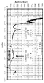
상기 과제를 해결하기 위하여, 본 발명의 일 형태는 충전 심도를 높일 때의 dQ/dVvsV 곡선에서 4.55V 부근에 넓은 피크를 가지는 양극 활물질을 제공한다. 이 넓은 피크는 이 부근에서 리튬을 추출하는 데 필요한 에너지의 변화가 적고, 결정 구조의 변화가 적은 것을 나타낸다. 그러므로 CoO2층이 어긋나거나 체적이 변화되는 것으로 인한 영향이 작아, 충전 심도가 높아도 비교적 안정적인 양극 활물질로 할 수 있다.In order to solve the above problems, one embodiment of the present invention provides a positive active material having a broad peak in the vicinity of 4.55V in the dQ / dVvsV curve when the depth of charge is increased. This broad peak indicates that the change in energy required to extract lithium is small in this vicinity and the change in the crystal structure is small. Therefore, the influence of the CoO 2 layer shifting or volume change is small, and thus a relatively stable positive electrode active material can be obtained even if the depth of charge is high.
또는 본 발명의 일 형태에서는, 충전 전압이 4.6V 이상 4.8V 이하, 충전 심도가 0.8 이상 0.9 미만이 되는 경우에도 H1-3형 구조가 되지 않고, CoO2층의 어긋남이 억제된 결정 구조를 유지할 수 있는 양극 활물질을 제공한다.Alternatively, in one embodiment of the present invention, even when the charging voltage is 4.6 V or more and 4.8 V or less and the charging depth is 0.8 or more and less than 0.9, the H1-3 type structure is not formed, and the crystal structure in which the CoO 2 layer shift is suppressed is maintained. A positive electrode active material that can be
더 구체적으로, 본 발명의 일 형태는 양극을 포함하는 이차 전지이고, 상기 양극을 양극으로서 사용하고, 리튬 금속을 음극에 사용하고, 1mol/L의 육플루오린화 인산 리튬, 및 에틸렌카보네이트(EC)와 다이에틸카보네이트(DEC)를 EC:DEC=3:7(체적비)로, 바이닐렌카보네이트를 2wt%로 포함하는 혼합물을 전해액에 사용하여 전지를 제작한 경우에, 상기 전지를 25℃의 환경하에서 4.9V까지 10mA/g로 충전하였을 때 측정된, 용량(Q)을 전압(V)으로 미분함으로써(dQ/dV) 얻어지는 dQ/dVvsV 곡선이 4.5V 이상 4.6V 이하의 범위에 피크를 가지고, 피크는 반치전폭이 0.10 이상인 이차 전지이다.More specifically, one embodiment of the present invention is a secondary battery including a positive electrode, using the positive electrode as the positive electrode, using lithium metal for the negative electrode, 1 mol/L lithium hexafluoride phosphate, and ethylene carbonate (EC) and diethyl carbonate (DEC) at EC:DEC=3:7 (volume ratio) and vinylene carbonate at 2 wt% when the battery was manufactured using an electrolyte solution, the battery was The dQ/dVvsV curve obtained by differentiating capacity (Q) with voltage (V) (dQ/dV), measured when charging at 10 mA/g to 4.9 V, has a peak in the range of 4.5 V or more and 4.6 V or less, and has a peak is a secondary battery having a full width at half maximum of 0.10 or more.
또한 본 발명의 일 형태는 양극을 포함하는 이차 전지이고, 상기 양극을 양극으로서 사용하고, 리튬 금속을 음극에 사용하고, 1mol/L의 육플루오린화 인산 리튬, 및 에틸렌카보네이트(EC)와 다이에틸카보네이트(DEC)를 EC:DEC=3:7(체적비)로, 바이닐렌카보네이트를 2wt%로 포함하는 혼합물을 전해액에 사용하여 전지를 제작한 경우에, 상기 전지를 25℃의 환경하에서 4.9V까지 10mA/g로 충전하였을 때 측정된, 용량(Q)을 전압(V)으로 미분함으로써(dQ/dV) 얻어지는 dQ/dVvsV 곡선이 4.5V 이상 4.6V 이하의 범위에 제 1 피크를 가지고, 4.15V 이상 4.25V 이하의 범위에 제 2 피크를 가지고, 제 1 피크의 강도(P1)와 제 2 피크의 강도(P2)의 비율(P1/P2)이 0.8 이하인 이차 전지이다.In addition, one embodiment of the present invention is a secondary battery including a positive electrode, using the positive electrode as the positive electrode, using lithium metal for the negative electrode, 1 mol/L lithium hexafluoride phosphate, and ethylene carbonate (EC) and diethyl When a battery is manufactured by using a mixture containing carbonate (DEC) in EC:DEC=3:7 (volume ratio) and vinylene carbonate in an electrolyte solution of 2 wt%, the battery is heated to 4.9V under an environment of 25°C. A dQ/dVvsV curve obtained by differentiating capacity (Q) with voltage (V) (dQ/dV), measured when charging at 10 mA/g, has a first peak in the range of 4.5V or more and 4.6V or less, 4.15V A secondary battery having a second peak in the range of 4.25V or less and having a ratio (P1/P2) of the intensity of the first peak (P1) to the intensity of the second peak (P2) of 0.8 or less.
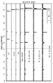
또한 본 발명의 일 형태는 양극을 포함하는 이차 전지이고, 상기 양극을 양극으로서 사용하고, 리튬 금속을 음극에 사용하고, 1mol/L의 육플루오린화 인산 리튬, 및 에틸렌카보네이트(EC)와 다이에틸카보네이트(DEC)를 EC:DEC=3:7(체적비)로, 바이닐렌카보네이트를 2wt%로 포함하는 혼합물을 전해액에 사용하여 전지를 제작한 경우에, 상기 전지를 45℃의 환경하에서 4.75V까지 10mA/g로 정전류 충전한 후, 아르곤 분위기에서 상기 전지의 양극을 CuKα1선을 사용한 분말 X선 회절로 분석하였을 때, XRD 패턴은 적어도 2θ=19.47±0.10° 및 2θ=45.62±0.05°에 회절 피크를 가지는 이차 전지이다.In addition, one embodiment of the present invention is a secondary battery including a positive electrode, using the positive electrode as the positive electrode, using lithium metal for the negative electrode, 1 mol/L lithium hexafluoride phosphate, and ethylene carbonate (EC) and diethyl When a battery is manufactured using a mixture containing carbonate (DEC) in EC:DEC=3:7 (volume ratio) and vinylene carbonate in an electrolyte solution of 2 wt%, the battery is heated to 4.75V under an environment of 45°C. When the positive electrode of the battery was analyzed by powder X-ray diffraction using CuKα 1 ray in an argon atmosphere after constant current charging at 10 mA/g, the XRD pattern was diffracted at at least 2θ=19.47±0.10° and 2θ=45.62±0.05° It is a secondary battery having a peak.
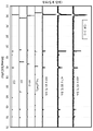
또한 본 발명의 일 형태는 양극을 포함하는 이차 전지이고, 상기 양극을 양극으로서 사용하고, 리튬 금속을 음극에 사용하고, 1mol/L의 육플루오린화 인산 리튬, 및 에틸렌카보네이트(EC)와 다이에틸카보네이트(DEC)를 EC:DEC=3:7(체적비)로, 바이닐렌카보네이트를 2wt%로 포함하는 혼합물을 전해액에 사용하여 전지를 제작한 경우에, 상기 전지를 25℃의 환경하에서 4.8V까지 100mA/g로 정전류 충전하고 나서 10mA/g가 될 때까지 정전압 충전하는 충전과, 2.5V까지 100mA/g로 정전류 방전하는 방전을 4번씩 반복한 후에, 4.8V까지 10mA/g로 정전류 충전하고 나서 아르곤 분위기에서 상기 전지의 양극을 CuKα1선을 사용한 분말 X선 회절로 분석하였을 때, XRD 패턴은 적어도 2θ=19.47±0.10° 및 2θ=45.62±0.05°에 회절 피크를 가지는 이차 전지이다.In addition, one embodiment of the present invention is a secondary battery including a positive electrode, using the positive electrode as the positive electrode, using lithium metal for the negative electrode, 1 mol/L lithium hexafluoride phosphate, and ethylene carbonate (EC) and diethyl When a battery is manufactured using a mixture containing carbonate (DEC) in EC:DEC=3:7 (volume ratio) and vinylene carbonate in an electrolyte solution of 2 wt%, the battery is heated to 4.8V under an environment of 25°C. After constant current charging at 100 mA/g, constant voltage charging until 10 mA/g, and discharging at 100 mA/g constant current to 2.5 V are repeated 4 times each, after constant current charging to 4.8 V at 10 mA/g When the positive electrode of the battery was analyzed by powder X-ray diffraction using CuKα 1 ray in an argon atmosphere, the XRD pattern was a secondary battery having diffraction peaks at least at 2θ=19.47±0.10° and 2θ=45.62±0.05°.
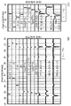
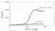
또한 본 발명의 일 형태는, 충방전 사이클의 초기에서, 전류 휴지법으로 측정되는 응답이 빠른 저항 성분 R(0.1s)가 n번째(n은 1보다 큰 자연수)의 방전보다 n+1번째의 방전에서 작고, n번째의 방전 용량보다 n+1번째의 방전 용량이 큰 이차 전지이다.Further, in one embodiment of the present invention, at the initial stage of the charge/discharge cycle, the resistance component R (0.1s), which has a fast response measured by the current pause method, is higher than the nth (n is a natural number greater than 1) discharge of the n+1th. It is a secondary battery which is small in discharge and has a larger n+1-th discharge capacity than an n-th discharge capacity.
또한 본 발명의 일 형태는 충방전 사이클에서, 전류값이 100mA/g인 정전류 방전을 5분 동안 수행하는 제 1 단계와, 충전 및 방전을 수행하지 않는 휴지를 2분 동안 수행하는 제 2 단계를 가지고, 제 2 단계의 시작부터 0.1초 후의 전압과 제 1 단계의 마지막 전압의 차이를 전류값으로 나눈 값을 응답이 빠른 저항 성분 R(0.1s)로 한 경우, 응답이 빠른 저항 성분 R(0.1s)는 2번째 이후 10번째 이전의 방전에서 최솟값을 가지고, 2번째 이후 10번째 이전의 방전에서 가장 큰 방전 용량을 가지는 이차 전지이다.Also, in one aspect of the present invention, in a charge/discharge cycle, a first step of performing a constant current discharge having a current value of 100 mA/g for 5 minutes, and a second step of performing a pause in which charging and discharging are not performed for 2 minutes If the value obtained by dividing the difference between the voltage 0.1 seconds after the start of the second stage and the last voltage of the first stage by the current value is taken as the resistance component R(0.1s) with the fast response, then the resistance component R(0.1s) with the fast response s) is a secondary battery having a minimum value in the second after the 10th discharge and the largest discharge capacity in the second after the 10th discharge.
또한 상기에서, 양극의 양극 활물질은 층상 암염형 결정 구조를 가지는 것이 바람직하다.In addition, in the above, the positive electrode active material of the positive electrode preferably has a layered rock salt crystal structure.
또한 상기에서, 양극의 양극 활물질이 가지는 전이 금속 M은 90atomic% 이상이 코발트인 것이 바람직하다.In addition, in the above, it is preferable that 90 atomic% or more of the transition metal M of the positive electrode active material of the positive electrode is cobalt.
또한 본 발명의 일 형태는 상기 이차 전지와, 표시부와, 센서를 가지는 전자 기기이다.Another embodiment of the present invention is an electronic device including the secondary battery, a display unit, and a sensor.
본 발명의 일 형태에 의하여, 리튬 이온 이차 전지에 사용할 수 있고, 충방전 사이클에 따른 충방전 용량의 저하가 억제된 양극 활물질 또는 복합 산화물을 제공할 수 있다. 또는 충방전을 반복하여도 결정 구조가 무너지기 어려운 양극 활물질 또는 복합 산화물을 제공할 수 있다. 또는 충방전 용량이 큰 양극 활물질 또는 복합 산화물을 제공할 수 있다. 또는 안전성 또는 신뢰성이 높은 이차 전지를 제공할 수 있다.According to one aspect of the present invention, it is possible to provide a positive electrode active material or a composite oxide that can be used for a lithium ion secondary battery and in which a decrease in charge/discharge capacity due to a charge/discharge cycle is suppressed. Alternatively, it is possible to provide a positive electrode active material or a composite oxide whose crystal structure is difficult to collapse even after repeated charging and discharging. Alternatively, a positive electrode active material or a composite oxide having a large charge/discharge capacity may be provided. Alternatively, a secondary battery having high safety or reliability may be provided.
또한 본 발명의 일 형태에 의하여 양극 활물질, 축전 장치, 또는 이들의 제작 방법을 제공할 수 있다.Further, according to one embodiment of the present invention, a positive electrode active material, a power storage device, or a manufacturing method thereof can be provided.
또한 이들 효과의 기재는 다른 효과의 존재를 방해하는 것은 아니다. 또한 본 발명의 일 형태는 이들 효과 모두를 반드시 가질 필요는 없다. 또한 이들 외의 효과는 명세서, 도면, 청구항 등의 기재로부터 저절로 명백해지는 것이며, 명세서, 도면, 청구항 등의 기재에서 이들 외의 효과가 추출될 수 있다.In addition, the description of these effects does not prevent the existence of other effects. In addition, one embodiment of the present invention does not necessarily have all of these effects. In addition, effects other than these will become apparent from the description of the specification, drawings, and claims, and other effects may be extracted from the description of the specification, drawings, and claims.
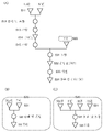
도 1은 양극 활물질의 제작 방법을 설명하는 도면이다.
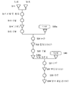
도 2는 양극 활물질의 제작 방법을 설명하는 도면이다.
도 3의 (A) 내지 (C)는 양극 활물질의 제작 방법을 설명하는 도면이다.
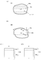
도 4의 (A)는 양극 활물질의 단면도이고, 도 4의 (B1) 내지 (C2)는 양극 활물질의 단면도의 일부를 나타낸 것이다.
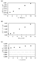
도 5의 (A1) 내지 (B)는 마그네슘의 분포와 결정면에 대하여 계산한 결과를 나타낸 것이다.
도 6의 (A) 및 (B)는 양극 활물질의 단면도이고, 도 6의 (C1) 및 (C2)는 양극 활물질의 단면도의 일부를 나타낸 것이다.
도 7은 양극 활물질의 단면도이다.
도 8은 양극 활물질의 단면도이다.
도 9는 양극 활물질의 충전 심도와 결정 구조를 설명하는 도면이다.
도 10은 결정 구조에서 계산되는 XRD 패턴을 나타낸 도면이다.
도 11은 비교예의 양극 활물질의 충전 심도와 결정 구조를 설명하는 도면이다.
도 12는 결정 구조에서 계산되는 XRD 패턴을 나타낸 도면이다.
도 13의 (A) 및 (B)는 결정 구조에서 계산되는 XRD 패턴을 나타낸 도면이다.
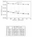
도 14의 (A) 내지 (C)는 XRD에서 산출되는 격자 상수를 나타낸 것이다.
도 15의 (A) 내지 (C)는 XRD에서 산출되는 격자 상수를 나타낸 것이다.
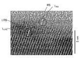
도 16은 결정의 배향이 실질적으로 일치되는 TEM 이미지의 예이다.
도 17의 (A)는 결정의 배향이 실질적으로 일치되는 STEM 이미지의 예이고, 도 17의 (B)는 암염형 결정 구조(RS)의 영역의 FFT 패턴을 나타낸 것이고, 도 17의 (C)는 층상 암염형 결정(LRS)의 영역의 FFT 패턴을 나타낸 것이다.
도 18의 (A) 및 (B)는 도전재로서 그래핀 화합물을 사용한 경우의 활물질층의 단면도이다.
도 19의 (A) 및 (B)는 이차 전지의 예를 설명하는 도면이다.
도 20의 (A) 내지 (C)는 이차 전지의 예를 설명하는 도면이다.
도 21의 (A) 및 (B)는 이차 전지의 예를 설명하는 도면이다.
도 22의 (A) 내지 (C)는 코인형 이차 전지를 설명하는 도면이다.
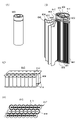
도 23의 (A) 내지 (D)는 원통형 이차 전지를 설명하는 도면이다.
도 24의 (A) 및 (B)는 이차 전지의 예를 설명하는 도면이다.
도 25의 (A) 내지 (D)는 이차 전지의 예를 설명하는 도면이다.
도 26의 (A) 및 (B)는 이차 전지의 예를 설명하는 도면이다.
도 27은 이차 전지의 예를 설명하는 도면이다.
도 28의 (A) 내지 (C)는 래미네이트형 이차 전지를 설명하는 도면이다.
도 29의 (A) 및 (B)는 래미네이트형 이차 전지를 설명하는 도면이다.
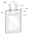
도 30은 이차 전지의 외관을 나타낸 도면이다.
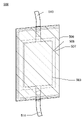
도 31은 이차 전지의 외관을 나타낸 도면이다.
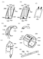
도 32의 (A) 내지 (C)는 이차 전지의 제작 방법을 설명하는 도면이다.
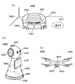
도 33의 (A) 내지 (H)는 전자 기기의 일례를 설명하는 도면이다.
도 34의 (A) 내지 (C)는 전자 기기의 일례를 설명하는 도면이다.
도 35는 전자 기기의 일례를 설명하는 도면이다.
도 36의 (A) 내지 (D)는 전자 기기의 일례를 설명하는 도면이다.
도 37의 (A) 내지 (C)는 전자 기기의 일례를 나타낸 도면이다.
도 38의 (A) 내지 (C)는 차량의 일례를 설명하는 도면이다.
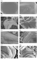
도 39의 (A) 내지 (F)는 양극 활물질의 표면 SEM 이미지이다.
도 40의 (A) 내지 (H)는 양극 활물질의 표면 SEM 이미지이다.
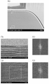
도 41의 (A), (B), 및 (D)는 양극 활물질의 단면 STEM 이미지이고, 도 41의 (C) 및 (E)는 FFT 패턴을 나타낸 것이다.
도 42의 (A)는 양극 활물질의 단면 STEM 이미지이고, 도 42의 (B1) 내지 (D2)는 EDX 매핑 이미지이다.
도 43의 (A1) 내지 (A3), (B1) 내지 (B3), (C1), (C2-1), (C3-1), (C2-2), (C3-2)는 양극 활물질의 단면 STEM 이미지이고, 도 43의 (A4) 내지 (A6), (B4) 내지 (B6), (C4-1) 내지 (C6-1), (C4-2) 내지 (C6-2)는 EDX 매핑 이미지이다.
도 44의 (A1) 내지 (A3), (B1) 내지 (B3), (C1), (C2-1), (C3-1), (C2-2), (C3-2)는 양극 활물질의 단면 STEM 이미지이고, 도 44의 (A4) 내지 (A6), (B4) 내지 (B6), (C4-1) 내지 (C6-1), (C4-2) 내지 (C6-2)는 EDX 매핑 이미지이다.
도 45의 (A) 및 (B)는 양극 활물질의 입도 분포의 측정 결과를 나타낸 것이다.
도 46의 (A) 내지 (C)는 양극 활물질의 표면 SEM 이미지이다.
도 47의 (A) 내지 (C)는 양극 활물질의 그레이 스케일값의 분포를 나타낸 그래프이다.
도 48의 (A) 내지 (C)는 양극 활물질의 휘도 히스토그램이다.
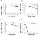
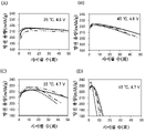
도 49의 (A) 내지 (D)는 이차 전지의 사이클 특성을 나타낸 그래프이다.
도 50의 (A) 내지 (D)는 이차 전지의 사이클 특성을 나타낸 그래프이다.
도 51의 (A) 내지 (D)는 이차 전지의 사이클 특성을 나타낸 그래프이다.
도 52의 (A) 내지 (D)는 이차 전지의 사이클 특성을 나타낸 그래프이다.
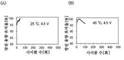
도 53의 (A) 및 (B)는 이차 전지의 사이클 특성을 나타낸 그래프이다.
도 54의 (A)는 LCO 펠릿의 사진이고, 도 54의 (B) 및 (C)는 양극 활물질의 표면 SEM 이미지이다.
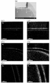
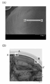
도 55의 (A)는 양극 활물질의 표면 SEM 이미지이고, 도 55의 (B)는 양극 활물질의 단면 STEM 이미지이다.
도 56의 (A1) 및 (B1)은 양극 활물질의 단면 HAADF-STEM 이미지이고, 도 56의 (A2) 내지 (A4) 및 (B2) 내지 (B4)는 EDX 매핑 이미지이다.
도 57은 이차 전지의 dQ/dVvsV 곡선을 나타낸 것이다.
도 58은 이차 전지의 dQ/dVvsV 곡선을 나타낸 것이다.
도 59는 이차 전지의 dQ/dVvsV 곡선을 나타낸 것이다.
도 60은 양극의 XRD 패턴을 나타낸 것이다.
도 61의 (A) 및 (B)는 도 60의 일부를 확대한 XRD 패턴을 나타낸 것이다.
도 62는 양극의 XRD 패턴을 나타낸 것이다.
도 63의 (A) 및 (B)는 도 62의 일부를 확대한 XRD 패턴을 나타낸 것이다.
도 64는 양극의 XRD 패턴을 나타낸 것이다.
도 65의 (A) 및 (B)는 도 64의 일부를 확대한 XRD 패턴을 나타낸 것이다.
도 66은 양극의 XRD 패턴을 나타낸 것이다.
도 67의 (A) 및 (B)는 도 66의 일부를 확대한 XRD 패턴을 나타낸 것이다.
도 68은 양극의 XRD 패턴을 나타낸 것이다.
도 69의 (A) 및 (B)는 도 68의 일부를 확대한 XRD 패턴을 나타낸 것이다.
도 70은 양극의 XRD 패턴을 나타낸 것이다.
도 71의 (A) 및 (B)는 도 70의 일부를 확대한 XRD 패턴을 나타낸 것이다.
도 72는 양극의 XRD 패턴을 나타낸 것이다.
도 73의 (A) 및 (B)는 도 72의 일부를 확대한 XRD 패턴을 나타낸 것이다.
도 74는 양극의 XRD 패턴을 나타낸 것이다.
도 75의 (A) 및 (B)는 도 74의 일부를 확대한 XRD 패턴을 나타낸 것이다.
도 76은 양극의 XRD 패턴을 나타낸 것이다.
도 77의 (A) 및 (B)는 도 76의 일부를 확대한 XRD 패턴을 나타낸 것이다.
도 78은 분체 저항 측정에 관한 도면이다.
도 79는 전류 휴지법을 사용한 측정의 방전 커브를 나타낸 그래프이다.
도 80은 전류 휴지법을 사용한 측정의 해석 방법을 나타낸 도면이다.
도 81의 (A) 및 (B)는 전류 휴지법을 사용한 측정의 해석 결과를 나타낸 도면이다.
도 82는 전류 휴지법을 사용한 측정의 해석 방법을 나타낸 도면이다.1 is a view for explaining a method of manufacturing a cathode active material.
2 is a view for explaining a method of manufacturing a positive electrode active material.
3A to 3C are diagrams for explaining a method of manufacturing a positive electrode active material.
4A is a cross-sectional view of a positive electrode active material, and FIGS. 4 (B1) to (C2) are partial cross-sectional views of the positive electrode active material.
5 (A1) to (B) show the results of calculations for magnesium distribution and crystal planes.
6A and 6B are cross-sectional views of the positive electrode active material, and FIGS. 6C1 and 6C2 are partial cross-sectional views of the positive electrode active material.
7 is a cross-sectional view of a positive active material.
8 is a cross-sectional view of a positive active material.
9 is a view for explaining a filling depth and a crystal structure of a positive electrode active material.
10 is a diagram illustrating an XRD pattern calculated in a crystal structure.
11 is a view for explaining a filling depth and a crystal structure of a positive active material of Comparative Example.
12 is a diagram illustrating an XRD pattern calculated in a crystal structure.
13 (A) and (B) are views showing XRD patterns calculated from the crystal structure.
14A to 14C show lattice constants calculated from XRD.
15A to 15C show lattice constants calculated from XRD.
16 is an example of a TEM image in which the orientation of crystals is substantially consistent.
Figure 17 (A) is an example of a STEM image in which the crystal orientation is substantially matched, Figure 17 (B) is an FFT pattern of the region of the rock salt crystal structure (RS), Figure 17 (C) shows the FFT pattern of the region of the layered rock salt crystal (LRS).
18A and 18B are cross-sectional views of the active material layer when a graphene compound is used as a conductive material.
19A and 19B are diagrams for explaining an example of a secondary battery.
20A to 20C are diagrams for explaining an example of a secondary battery.
21A and 21B are diagrams for explaining an example of a secondary battery.
22A to 22C are views for explaining a coin-type secondary battery.
23A to 23D are views for explaining a cylindrical secondary battery.
24A and 24B are diagrams for explaining an example of a secondary battery.
25A to 25D are views for explaining an example of a secondary battery.
26A and 26B are diagrams for explaining an example of a secondary battery.
27 is a view for explaining an example of a secondary battery.
28A to 28C are views for explaining a laminate type secondary battery.
29A and 29B are views for explaining a laminate type secondary battery.
30 is a view showing an external appearance of a secondary battery.
31 is a view showing an external appearance of a secondary battery.
32A to 32C are views for explaining a method of manufacturing a secondary battery.
33A to 33H are diagrams for explaining an example of an electronic device.
34A to 34C are diagrams for explaining an example of an electronic device.
It is a figure explaining an example of an electronic device.
36A to 36D are diagrams for explaining an example of an electronic device.
37A to 37C are diagrams showing an example of an electronic device.
38A to 38C are views for explaining an example of a vehicle.
39 (A) to (F) are surface SEM images of the positive electrode active material.
40 (A) to (H) are surface SEM images of the positive electrode active material.
41 (A), (B), and (D) are cross-sectional STEM images of a positive electrode active material, and FIGS. 41 (C) and (E) show an FFT pattern.
Figure 42 (A) is a cross-sectional STEM image of the positive electrode active material, Figure 42 (B1) to (D2) are EDX mapping images.
43 (A1) to (A3), (B1) to (B3), (C1), (C2-1), (C3-1), (C2-2), and (C3-2) are It is a cross-sectional STEM image, and (A4) to (A6), (B4) to (B6), (C4-1) to (C6-1), (C4-2) to (C6-2) of FIG. 43 are EDX mapping It is an image.
(A1) to (A3), (B1) to (B3), (C1), (C2-1), (C3-1), (C2-2), (C3-2) of FIG. 44 are It is a cross-sectional STEM image, and (A4) to (A6), (B4) to (B6), (C4-1) to (C6-1), (C4-2) to (C6-2) of FIG. 44 are EDX mapping It is an image.
45 (A) and (B) show the measurement results of the particle size distribution of the positive electrode active material.
46 (A) to (C) are surface SEM images of the positive electrode active material.
47 (A) to (C) are graphs showing the distribution of gray scale values of the positive active material.
48A to 48C are luminance histograms of the positive electrode active material.
49A to 49D are graphs illustrating cycle characteristics of the secondary battery.
50 (A) to (D) are graphs showing cycle characteristics of the secondary battery.
51 (A) to (D) are graphs showing the cycle characteristics of the secondary battery.
52A to 52D are graphs showing cycle characteristics of the secondary battery.
53 (A) and (B) are graphs showing the cycle characteristics of the secondary battery.
Figure 54 (A) is a photograph of LCO pellets, Figure 54 (B) and (C) are surface SEM images of the positive electrode active material.
55(A) is a surface SEM image of the positive active material, and FIG. 55(B) is a cross-sectional STEM image of the positive active material.
56 (A1) and (B1) are cross-sectional HAADF-STEM images of the positive electrode active material, and (A2) to (A4) and (B2) to (B4) of FIG. 56 are EDX mapping images.
57 shows a dQ/dVvsV curve of a secondary battery.
58 shows a dQ/dVvsV curve of a secondary battery.
59 shows a dQ/dVvsV curve of a secondary battery.
60 shows the XRD pattern of the anode.
61 (A) and (B) show an enlarged XRD pattern of a part of FIG.
62 shows the XRD pattern of the anode.
63 (A) and (B) show an enlarged XRD pattern of a part of FIG.
64 shows the XRD pattern of the anode.
65A and 65B show an enlarged XRD pattern of a part of FIG. 64 .
66 shows the XRD pattern of the anode.
67 (A) and (B) show an enlarged XRD pattern of a part of FIG.
68 shows the XRD pattern of the anode.
69 (A) and (B) show an enlarged XRD pattern of a part of FIG.
70 shows the XRD pattern of the anode.
71 (A) and (B) show an enlarged XRD pattern of a part of FIG. 70 .
72 shows the XRD pattern of the anode.
73 (A) and (B) show an enlarged XRD pattern of a part of FIG. 72 .
74 shows the XRD pattern of the anode.
75(A) and (B) show an enlarged XRD pattern of a part of FIG. 74 .
76 shows the XRD pattern of the anode.
77 (A) and (B) show an enlarged XRD pattern of a part of FIG. 76 .
78 is a diagram related to the powder resistance measurement.
Fig. 79 is a graph showing the discharge curve of measurement using the current pause method.
Fig. 80 is a diagram showing an analysis method of measurement using the current pause method.
81 (A) and (B) are diagrams showing analysis results of measurements using the current pause method.
Fig. 82 is a diagram showing an analysis method of measurement using the current pause method.
이하에서는 본 발명을 실시하기 위한 형태의 예에 대하여 도면 등을 사용하여 설명한다. 다만, 본 발명은 이하의 형태의 예에 한정하여 해석되는 것이 아니다. 본 발명의 취지를 벗어나지 않는 범위에서 발명을 실시하기 위한 형태를 변경할 수 있다.Hereinafter, an example of the form for implementing this invention is demonstrated using drawings etc. FIG. However, this invention is limited to the example of the following form and is not interpreted. Forms for carrying out the invention can be changed without departing from the spirit of the present invention.
본 명세서 등에서는 밀러 지수를 사용하여 결정면 및 결정 방향을 표기한다. 결정면을 나타내는 개별 면은 ( )를 사용하여 표기한다. 결정학에서 결정면, 결정 방향, 및 공간군은 숫자 위에 바를 붙여 표기하지만, 본 명세서 등에서는 서식에 제약이 있기 때문에 숫자 위에 바를 붙이는 대신에 숫자 앞에 -(마이너스 기호)를 붙여 표기하는 경우가 있다.In the present specification and the like, a crystal plane and a crystal direction are indicated using the Miller index. Individual faces representing crystal planes are indicated using ( ). In crystallography, crystal planes, crystal directions, and space groups are indicated by adding a bar on top of the number.
본 명세서 등에 있어서, 양극 활물질의 이론 용량이란 양극 활물질이 가지는 삽입·이탈 가능한 리튬이 모두 이탈되었을 때의 전기량을 말한다. 예를 들어 LiCoO2의 이론 용량은 274mAh/g이고, LiNiO2의 이론 용량은 274mAh/g이고, LiMn2O4의 이론 용량은 148mAh/g이다.In this specification and the like, the theoretical capacity of the positive electrode active material refers to the amount of electricity when all of the insertable/removable lithium of the positive electrode active material is released. For example, the theoretical capacity of LiCoO 2 is 274 mAh/g, the theoretical capacity of LiNiO 2 is 274 mAh/g, and the theoretical capacity of LiMn 2 O 4 is 148 mAh/g.
본 명세서에서, 충전 심도란 양극 활물질의 이론 용량을 기준으로, 어느 정도의 용량이 충전된 상태인지, 환언하면 어느 정도의 양의 리튬이 양극 활물질로부터 이탈된 상태인지를 나타내는 값이다. 예를 들어 코발트산 리튬(LiCoO2) 및 니켈-코발트-망가니즈산 리튬(LiNixCoyMnzO2(x+y+z=1)) 등, 층상 암염형 구조의 양극 활물질인 경우, 이론 용량인 274mAh/g를 기준으로, 충전 심도가 0인 경우에는 양극으로부터 리튬이 이탈되지 않은 상태를 말하고, 충전 심도가 0.5인 경우에는 137mAh/g에 상당하는 리튬이 양극 활물질로부터 이탈된 상태를 말하고, 충전 심도가 0.8인 경우에는 219.2mAh/g에 상당하는 리튬이 양극 활물질로부터 이탈된 상태를 말한다. 또한 LiaCoO2(0≤a≤1)와 같이 표기하는 경우, 충전 심도가 0인 경우에는 a가 1인 LiCoO2로 표기되고, 충전 심도가 0.5인 경우에는 a가 0.5인 Li0.5CoO2로 표기되고, 충전 심도가 0.8인 경우에는 a가 0.2인 Li0 . 2CoO2로 표기된다.In the present specification, the charge depth is a value indicating how much capacity is in a charged state, in other words, how much lithium is in a state desorbed from the positive active material, based on the theoretical capacity of the positive electrode active material. For example, in the case of a positive electrode active material having a layered rock salt structure, such as lithium cobaltate (LiCoO 2 ) and nickel-cobalt-lithium manganate (LiNi x Co y Mn z O 2 (x+y+z=1)), Based on the theoretical capacity of 274 mAh/g, when the charging depth is 0, lithium is not released from the positive electrode, and when the charging depth is 0.5, lithium equivalent to 137 mAh/g is separated from the positive electrode active material. In other words, when the charging depth is 0.8, lithium corresponding to 219.2 mAh/g is separated from the positive electrode active material. In addition, when expressed as Li a CoO 2 (0≤a≤1), when the charging depth is 0, a is 1 LiCoO 2 , and when the charging depth is 0.5, a is 0.5 Li 0.5 CoO 2 , and when the depth of charge is 0.8, a is Li 0 . It is denoted as 2 CoO 2 .
또한 본 명세서 등에서, 어떤 수치 A의 근방의 값이란, 0.9ХA 이상 1.1ХA 이하의 값을 가리키는 것으로 한다.In addition, in this specification and the like, a value in the vicinity of a certain numerical value A shall indicate a value of 0.9 ХA or more and 1.1 ХA or less.
또한 본 명세서 등에서, 본 발명의 일 형태의 양극 및 양극 활물질을 사용한 이차 전지로서, 상대 전극에 리튬 금속을 사용하는 예를 나타내는 경우가 있지만, 본 발명의 일 형태의 이차 전지는 이에 한정되지 않는다. 음극에 다른 재료, 예를 들어 흑연, 타이타늄산 리튬 등을 사용하여도 좋다. 본 발명의 일 형태의 양극 및 양극 활물질이 가지는, 충방전을 반복하여도 결정 구조가 무너지기 어렵고 양호한 사이클 특성을 얻을 수 있다는 등의 성질은 음극의 재료로부터 영향을 받지 않는다. 또한 본 발명의 일 형태의 이차 전지에 대하여, 상대 전극에 리튬을 사용하고, 일반적인 충전 전압보다 높은 전압인 4.7V 정도의 충전 전압으로 충방전하는 예를 나타내는 경우가 있지만, 더 낮은 전압으로 충방전을 하여도 좋다. 더 낮은 전압으로 충방전하는 경우에는 본 명세서 등에서 제시하는 것보다 사이클 특성이 더 좋아지는 것으로 전망된다.In addition, in this specification and the like, examples in which lithium metal is used as a counter electrode as a secondary battery using the positive electrode and the positive electrode active material of one embodiment of the present invention are sometimes shown, but the secondary battery of one embodiment of the present invention is not limited thereto. Other materials, such as graphite, lithium titanate, etc., may be used for the negative electrode. The properties of the positive electrode and the positive electrode active material of one embodiment of the present invention that the crystal structure is less likely to collapse even after repeated charging and discharging and good cycle characteristics can be obtained are not affected by the material of the negative electrode. In addition, with respect to the secondary battery of one embodiment of the present invention, an example of charging and discharging at a charging voltage of about 4.7 V, which is a voltage higher than a general charging voltage, using lithium as a counter electrode is shown in some cases, but charging and discharging at a lower voltage may do In the case of charging and discharging at a lower voltage, cycle characteristics are expected to be better than those presented in this specification and the like.
또한 본 명세서 등에서, 특별히 언급하지 않는 한 충전 전압 및 방전 전압은 상대 전극에 리튬을 사용한 경우의 전압을 가리킨다. 다만, 같은 양극이어도 음극에 사용하는 재료에 따라 이차 전지의 충방전 전압은 변화된다. 예를 들어 흑연의 전위는 약 0.1V(vs Li/Li+)이기 때문에, 음극이 흑연인 경우에는 상대 전극에 리튬을 사용한 경우보다 충방전 전압이 약 0.1V 낮아진다. 또한 본 명세서에서 이차 전지의 충전 전압이 예를 들어 4.7V 이상인 경우에도, 방전 전압의 플래토 영역이 4.7V 이상일 필요는 없다.In addition, in this specification and the like, unless otherwise specified, the charging voltage and the discharging voltage refer to the voltage when lithium is used for the counter electrode. However, even with the same positive electrode, the charging/discharging voltage of the secondary battery varies depending on the material used for the negative electrode. For example, since the potential of graphite is about 0.1 V (vs Li/Li + ), when the negative electrode is graphite, the charge/discharge voltage is about 0.1 V lower than when lithium is used as the counter electrode. Also, in the present specification, even when the charging voltage of the secondary battery is, for example, 4.7V or more, the plateau region of the discharge voltage does not need to be 4.7V or more.
(실시형태 1)(Embodiment 1)
본 실시형태에서는, 본 발명을 실시하기 위한 일 형태인 양극 활물질의 제작 방법에 대하여 설명한다.In this embodiment, the manufacturing method of the positive electrode active material which is one aspect for implementing this invention is demonstrated.
<<양극 활물질의 제작 방법 1>><<
<단계 S11><Step S11>
도 1의 (A)에 나타낸 단계 S11에서는, 출발 재료인 리튬 및 전이 금속의 재료로서 각각 리튬원(Li원) 및 전이 금속(M)원(M원)을 준비한다.In step S11 shown in FIG. 1A, a lithium source (Li source) and a transition metal (M) source (M source) are prepared as starting materials for lithium and transition metal, respectively.
리튬원으로서는, 리튬을 가지는 화합물을 사용하는 것이 바람직하고, 예를 들어 탄산 리튬, 수산화 리튬, 질산 리튬, 또는 플루오린화 리튬 등을 사용할 수 있다. 리튬원은 순도가 높은 것이 바람직하고, 예를 들어 순도가 99.99% 이상인 재료를 사용하는 것이 좋다.As a lithium source, it is preferable to use the compound which has lithium, For example, lithium carbonate, lithium hydroxide, lithium nitrate, lithium fluoride, etc. can be used. The lithium source is preferably high in purity, for example, it is preferable to use a material having a purity of 99.99% or more.
전이 금속 M은 주기율표에서 4족 내지 13족에 기재된 원소 중에서 선택할 수 있고, 예를 들어 망가니즈, 코발트, 및 니켈 중 적어도 하나를 사용한다. 전이 금속 M으로서, 코발트만 사용하는 경우, 니켈만 사용하는 경우, 코발트와 망가니즈의 2종류를 사용하는 경우, 코발트와 니켈의 2종류를 사용하는 경우, 또는 코발트, 망가니즈, 니켈의 3종류를 사용하는 경우가 있다. 코발트만 사용하는 경우, 얻어지는 양극 활물질은 코발트산 리튬(LCO)을 가지고, 코발트, 망가니즈, 및 니켈의 3종류를 사용하는 경우, 얻어지는 양극 활물질은 니켈-코발트-망가니즈산 리튬(NCM)을 가진다.The transition metal M may be selected from elements described in
전이 금속(M)원으로서, 상기 전이 금속 M을 가지는 화합물을 사용하는 것이 바람직하고, 예를 들어 상기 전이 금속 M으로서 예시된 금속의 산화물 또는 금속의 수산화물 등을 사용할 수 있다. 코발트원으로서는, 산화 코발트, 수산화 코발트 등을 사용할 수 있다. 망가니즈원으로서는, 산화 망가니즈, 수산화 망가니즈 등을 사용할 수 있다. 니켈원으로서는, 산화 니켈, 수산화 니켈 등을 사용할 수 있다. 알루미늄원으로서는, 산화 알루미늄, 수산화 알루미늄 등을 사용할 수 있다.As the transition metal (M) source, it is preferable to use a compound having the transition metal M, for example, an oxide or a hydroxide of a metal exemplified as the transition metal M can be used. As a cobalt source, cobalt oxide, cobalt hydroxide, etc. can be used. As a manganese source, manganese oxide, manganese hydroxide, etc. can be used. As a nickel source, nickel oxide, nickel hydroxide, etc. can be used. As an aluminum source, aluminum oxide, aluminum hydroxide, etc. can be used.
전이 금속(M)원은 순도가 높은 것이 바람직하고, 예를 들어 순도가 3N(99.9%) 이상, 바람직하게는 4N(99.99%) 이상, 더 바람직하게는 4N5(99.995%) 이상, 더욱 바람직하게는 5N(99.999%) 이상인 재료를 사용하는 것이 좋다. 순도가 높은 재료를 사용함으로써, 양극 활물질의 불순물을 제어할 수 있다. 그 결과, 이차 전지의 용량의 증가 및/또는 이차 전지의 신뢰성 향상이 이루어진다.The transition metal (M) source is preferably of high purity, for example, having a purity of 3N (99.9%) or more, preferably 4N (99.99%) or more, more preferably 4N5 (99.995%) or more, still more preferably It is recommended to use a material of 5N (99.999%) or more. By using a material with high purity, impurities in the positive electrode active material can be controlled. As a result, the capacity of the secondary battery is increased and/or the reliability of the secondary battery is improved.
이에 더하여, 전이 금속원의 결정성이 높은 것이 바람직하고, 예를 들어 단결정립을 가지는 것이 좋다. 전이 금속원의 결정성을 평가하는 경우, TEM(투과 전자 현미경) 이미지, STEM(주사 투과 전자 현미경) 이미지, HAADF-STEM(고각 산란 환상 암시야 주사 투과 전자 현미경) 이미지, ABF-STEM(환상 명시야 주사 투과 전자 현미경) 이미지 등을 사용하여 평가하거나, 또는 X선 회절(XRD), 전자선 회절, 중성자선 회절 등을 사용하여 평가한다. 또한 상기 결정성 평가에 관한 방법은 전이 금속원뿐만 아니라, 상기 외의 결정성 평가에도 적용할 수 있다.In addition, it is preferable that the crystallinity of the transition metal source is high, for example, it is preferable to have single crystal grains. When evaluating the crystallinity of a transition metal source, TEM (transmission electron microscope) image, STEM (scanning transmission electron microscope) image, HAADF-STEM (high angle scattering annular dark field scanning transmission electron microscope) image, ABF-STEM (annular light Field of view scanning transmission electron microscopy) images or the like, or using X-ray diffraction (XRD), electron diffraction, neutron ray diffraction, or the like. In addition, the method related to the crystallinity evaluation can be applied not only to the transition metal source but also to the crystallinity evaluation other than the above.
또한 2개 이상의 전이 금속원을 사용하는 경우, 상기 2개 이상의 전이 금속원을 층상 암염형 결정 구조를 가질 수 있는 비율(혼합비)로 준비하는 것이 바람직하다.In addition, when two or more transition metal sources are used, it is preferable to prepare the two or more transition metal sources in a ratio (mixing ratio) capable of having a layered rock salt crystal structure.
<단계 S12><Step S12>
다음으로 도 1의 (A)에 나타낸 단계 S12에서, 리튬원 및 전이 금속원을 분쇄 및 혼합하여, 혼합 재료를 제작한다. 분쇄 및 혼합은 건식법 또는 습식법으로 수행할 수 있다. 습식법은 더 작게 해쇄할 수 있기 때문에 바람직하다. 습식법으로 수행하는 경우에는, 용매를 준비한다. 용매로서는 아세톤 등의 케톤, 에탄올 및 아이소프로판올 등의 알코올, 에터, 다이옥세인, 아세토나이트릴, N-메틸-2-피롤리돈(NMP) 등을 사용할 수 있다. 리튬과 반응하기 어려운 비양성자성 용매를 사용하는 것이 더 바람직하다. 본 실시형태에서는 순도가 99.5% 이상인 탈수 아세톤을 사용하는 것으로 한다. 수분 함유량을 10ppm 이하까지 낮춘, 순도가 99.5% 이상인 탈수 아세톤에 리튬원 및 전이 금속원을 혼합하여 분쇄 및 혼합을 수행하는 것이 적합하다. 상기와 같은 순도의 탈수 아세톤을 사용함으로써, 혼입 가능성이 있는 불순물을 저감할 수 있다.Next, in step S12 shown in FIG. 1A , a lithium source and a transition metal source are pulverized and mixed to prepare a mixed material. Grinding and mixing may be performed by a dry method or a wet method. The wet method is preferred because it allows for smaller pulverization. In the case of carrying out by the wet method, a solvent is prepared. As a solvent, ketones, such as acetone, alcohols, such as ethanol and isopropanol, ether, dioxane, acetonitrile, N-methyl-2-pyrrolidone (NMP), etc. can be used. It is more preferable to use an aprotic solvent that is difficult to react with lithium. In this embodiment, it is assumed that dehydrated acetone with a purity of 99.5% or more is used. It is suitable to perform grinding and mixing by mixing a lithium source and a transition metal source in dehydrated acetone having a purity of 99.5% or more with a moisture content of 10 ppm or less. By using dehydrated acetone of the above purity, impurities that may be mixed can be reduced.
분쇄 및 혼합에는 볼밀(ball mill) 또는 비드밀(bead mill) 등을 사용할 수 있다. 볼밀을 사용하는 경우에는, 분쇄 미디어로서 산화 알루미늄 볼 또는 산화 지르코늄 볼을 사용하는 것이 좋다. 산화 지르코늄 볼은 불순물의 배출이 적어 바람직하다. 또한 볼밀 또는 비드밀 등을 사용하는 경우, 미디어로 인한 오염을 억제하기 위하여, 주변 속도를 100mm/s 이상 2000mm/s 이하로 하는 것이 좋다. 본 실시형태에서는 주변 속도 838mm/s(회전수 400rpm, 볼밀의 직경 40mm)로 실시한다.A ball mill or a bead mill may be used for grinding and mixing. When using a ball mill, it is preferable to use aluminum oxide balls or zirconium oxide balls as grinding media. A zirconium oxide ball is preferable because the discharge of impurities is small. In addition, when using a ball mill or a bead mill, in order to suppress contamination due to media, it is recommended that the peripheral speed be set to 100 mm/s or more and 2000 mm/s or less. In this embodiment, it implements at a peripheral speed of 838 mm/s (
<단계 S13><Step S13>
다음으로 도 1의 (A)에 나타낸 단계 S13에서, 상기 혼합 재료를 가열한다. 가열은 800℃ 이상 1100℃ 이하에서 수행하는 것이 바람직하고, 900℃ 이상 1000℃ 이하에서 수행하는 것이 더 바람직하고, 950℃ 정도가 더욱 바람직하다. 온도가 지나치게 낮으면, 리튬원 및 전이 금속원의 분해 및 용융이 불충분해질 우려가 있다. 한편 온도가 지나치게 높으면, 리튬원으로부터의 리튬의 증산 및/또는 전이 금속원으로서 사용하는 금속의 과잉 환원 등이 원인이 되어 결함이 생길 우려가 있다. 상기 결함으로서는, 예를 들어 전이 금속으로서 코발트를 사용하는 경우에, 과잉으로 환원되면 코발트가 3가로부터 2가로 변화되어, 산소 결손 등이 유발되는 경우가 있다.Next, in step S13 shown in Fig. 1A, the mixed material is heated. Heating is preferably performed at 800°C or higher and 1100°C or lower, more preferably at 900°C or higher and 1000°C or lower, and still more preferably about 950°C. If the temperature is too low, decomposition and melting of the lithium source and the transition metal source may become insufficient. On the other hand, when the temperature is too high, transpiration of lithium from the lithium source and/or excessive reduction of the metal used as the transition metal source may cause defects, which may cause defects. As the above defect, for example, when cobalt is used as a transition metal, when it is reduced excessively, cobalt changes from trivalent to divalent, and oxygen vacancies or the like may be induced.
가열 시간은 1시간 이상 100시간 이하로 하는 것이 바람직하고, 2시간 이상 20시간 이하로 하는 것이 더 바람직하다.The heating time is preferably 1 hour or more and 100 hours or less, and more preferably 2 hours or more and 20 hours or less.
승온 레이트는, 가열 온도의 도달 온도에 따르지만 80℃/h 이상 250℃/h 이하가 좋다. 예를 들어 1000℃에서 10시간 동안 가열하는 경우, 승온 레이트는 200℃/h로 하는 것이 좋다.Although a temperature increase rate depends on the reached|attained temperature of a heating temperature, 80 degreeC/h or more and 250 degrees C/h or less are good. For example, when heating at 1000°C for 10 hours, it is preferable that the temperature increase rate be 200°C/h.
가열은 건조 공기 등, 물이 적은 분위기에서 수행하는 것이 바람직하고, 예를 들어 이슬점이 -50℃ 이하인 분위기가 바람직하고, -80℃ 이하인 분위기가 더 바람직하다. 본 실시형태에서는, 이슬점이 -93℃인 분위기에서 가열하는 것으로 한다. 또한 재료 내에 혼입될 가능성이 있는 불순물을 저감하기 위해서는 가열 분위기에서의 CH4, CO, CO2, 및 H2 등의 불순물 농도를 각각 5ppb(parts per billion) 이하로 하는 것이 좋다.The heating is preferably performed in an atmosphere with little water such as dry air, for example, an atmosphere having a dew point of -50°C or lower is preferred, and an atmosphere of -80°C or lower is more preferred. In this embodiment, it shall be heated in the atmosphere whose dew point is -93 degreeC. In addition, in order to reduce impurities that may be mixed into the material, it is preferable that the concentration of impurities such as CH 4 , CO, CO 2 , and H 2 in the heating atmosphere be 5 ppb (parts per billion) or less, respectively.
가열 분위기로서는, 산소를 포함하는 분위기가 바람직하다. 예를 들어 반응실에 건조 공기를 연속적으로 도입하는 방법이 있다. 이 경우, 건조 공기의 유량은 10L/min으로 하는 것이 바람직하다. 산소를 반응실에 연속적으로 도입하여, 산소가 반응실 내를 흐르도록 하는 방법을 플로(flow)라고 부른다.As a heating atmosphere, the atmosphere containing oxygen is preferable. For example, there is a method of continuously introducing dry air into the reaction chamber. In this case, it is preferable that the flow rate of dry air shall be 10 L/min. A method of continuously introducing oxygen into the reaction chamber so that oxygen flows through the reaction chamber is called a flow.
가열 분위기가 산소를 포함하는 분위기인 경우, 플로를 수행하지 않는 방법을 사용하여도 좋다. 예를 들어 반응실을 감압한 후에 산소를 충전하고('퍼지하다'라고 하여도 좋음), 그 이후에는 분위기가 반응실로부터 나가지 않도록, 또는 외부로부터 들어오지 않도록 하는 방법을 사용하여도 좋다. 예를 들어 반응실을 -970hPa까지 감압한 후에 50hPa까지 산소를 충전하면 좋다.When the heating atmosphere is an atmosphere containing oxygen, a method in which flow is not performed may be used. For example, after depressurizing the reaction chamber, oxygen may be charged (it may be referred to as 'purging'), and after that, a method may be used so that the atmosphere does not leave the reaction chamber or enter from the outside. For example, after the reaction chamber is depressurized to -970 hPa, oxygen may be charged up to 50 hPa.
가열 후에 냉각시킬 때는 자연 방랭으로 냉각시켜도 좋지만, 규정 온도에서 실온까지의 강온(降溫) 시간은 10시간 이상 50시간 이하인 것이 바람직하다. 다만, 반드시 실온까지 냉각시킬 필요는 없고, 다음 단계에서 허용되는 온도까지 냉각시키면 좋다.When cooling after heating, it may be cooled by natural cooling, but it is preferable that the temperature-fall time from the specified temperature to room temperature is 10 hours or more and 50 hours or less. However, it is not necessarily necessary to cool to room temperature, and it is sufficient to cool it to a temperature allowed in the next step.
본 공정에서의 가열에는 로터리 킬른 또는 롤러 하스 킬른(roller hearth kiln)을 사용하여도 좋다. 로터리 킬른을 사용하면 연속식과 배치식의 어느 방식에서도 교반하면서 가열할 수 있다.A rotary kiln or a roller hearth kiln may be used for heating in this process. If a rotary kiln is used, it can be heated with stirring in either continuous or batch mode.
가열 시에 사용하는 내화갑(sagger)(용기 또는 도가니라고 하여도 좋음)은 산화 알루미늄제인 것이 바람직하다. 산화 알루미늄제 내화갑은 불순물을 방출하지 않는 재질이다. 본 실시형태에서는 순도가 99.9%인 산화 알루미늄제 내화갑을 사용한다. 내화갑에 뚜껑을 덮고 가열하는 것이 바람직하다. 이로써 재료가 휘발되는 것을 방지할 수 있다.It is preferable that a sagger (it may also be called a container or a crucible) used for heating is made of aluminum oxide. The aluminum oxide saggar is a material that does not emit impurities. In the present embodiment, a saggar made of aluminum oxide having a purity of 99.9% is used. It is desirable to cover the saggar with a lid and heat it. This can prevent the material from volatilizing.
가열이 끝난 후에 필요에 따라 분쇄하고 나서 체로 치어도 좋다. 가열 후의 재료는 도가니로부터 막자사발로 이동시킨 후에 회수하여도 좋다. 또한 상기 막자사발로서는 산화 알루미늄제 막자사발을 사용하는 것이 적합하다. 산화 알루미늄제 막자사발은 불순물을 방출하지 않는 재질이다. 구체적으로는 순도가 90% 이상, 바람직하게는 99% 이상인 산화 알루미늄제 막자사발을 사용한다. 또한 단계 S13 외의 후술하는 가열 공정에서도 단계 S13과 동등한 가열 조건을 적용할 수 있다.After heating, if necessary, it may be pulverized and then sieved. The material after heating may be recovered after moving it from the crucible to the mortar. Moreover, it is suitable to use the mortar made from aluminum oxide as said mortar. The mortar made of aluminum oxide is a material that does not emit impurities. Specifically, a mortar made of aluminum oxide having a purity of 90% or more, preferably 99% or more is used. In addition, the heating conditions equivalent to those of step S13 may be applied in a heating process to be described later other than step S13.
<단계 S14><Step S14>
상술한 공정에 의하여, 도 1의 (A)에 나타낸 단계 S14에서 전이 금속을 가지는 복합 산화물(LiMO2)을 얻을 수 있다. 이 복합 산화물은 LiMO2로 표기되는 리튬 복합 산화물의 결정 구조를 가지면 좋고, 그 조성은 Li:M:O=1:1:2에 엄밀히 한정되는 것은 아니다. 전이 금속으로서 코발트를 사용한 경우, 이를 코발트를 가지는 복합 산화물이라고 부르고, LiCoO2로 표기된다. 그 조성은 Li:Co:O=1:1:2에 엄밀히 한정되는 것은 아니다.Through the above-described process, a composite oxide (LiMO 2 ) having a transition metal can be obtained in step S14 shown in FIG. 1A . This composite oxide may have a crystal structure of a lithium composite oxide represented by LiMO 2 , and the composition thereof is not strictly limited to Li:M:O=1:1:2. When cobalt is used as the transition metal, it is called a composite oxide having cobalt, and is denoted by LiCoO 2 . Its composition is not strictly limited to Li:Co:O=1:1:2.
단계 S11 내지 단계 S14에서는 고상법으로 복합 산화물을 제작하는 예를 나타내었지만, 공침법으로 복합 산화물을 제작하여도 좋다. 또한 수열법으로 복합 산화물을 제작하여도 좋다.In steps S11 to S14, examples of producing the composite oxide by the solid-phase method are shown, but the composite oxide may be produced by the co-precipitation method. Alternatively, the composite oxide may be produced by a hydrothermal method.
<단계 S15><Step S15>
다음으로, 도 1의 (A)에 나타낸 단계 S15에서 상기 복합 산화물을 가열한다. 복합 산화물에 대하여 처음으로 실시되는 가열이기 때문에, 단계 S15에서의 가열을 초기 가열이라고 부르는 경우가 있다. 초기 가열을 거치면 복합 산화물의 표면이 매끈해진다. '표면이 매끈하다'란, 요철이 적고, 복합 산화물이 전체적으로 둥근 모양을 가지며, 모서리 부분도 둥근 모양을 가지는 것을 말한다. 또한 표면에 부착된 이물질이 적은 상태를 매끈하다고 한다. 이물질은 요철의 요인으로 생각되기 때문에, 표면에 부착되지 않는 것이 바람직하다.Next, the composite oxide is heated in step S15 shown in FIG. 1A. Since this is the first heating performed on the composite oxide, the heating in step S15 is sometimes referred to as initial heating. After initial heating, the surface of the composite oxide becomes smooth. 'Smooth surface' means that there are few irregularities, the composite oxide has a round shape as a whole, and the corners have a round shape. In addition, a state in which there are few foreign substances attached to the surface is said to be smooth. Since a foreign material is considered to be a factor of unevenness, it is preferable that it does not adhere to the surface.
초기 가열은 복합 산화물로서 완성된 후에 가열하는 것을 가리키고, 본 발명자들은 표면을 매끈하게 하기 위하여 초기 가열을 실시함으로써 충방전 후의 열화를 저감할 수 있다는 것을 발견하였다. 표면을 매끈하게 하기 위한 초기 가열에서는 리튬 화합물원을 준비하지 않아도 된다.Initial heating refers to heating after completion as a composite oxide, and the present inventors have discovered that deterioration after charging and discharging can be reduced by performing initial heating in order to smooth the surface. In the initial heating for smoothing the surface, it is not necessary to prepare a lithium compound source.
또는 표면을 매끈하게 하기 위한 초기 가열에서는 첨가 원소원을 준비하지 않아도 된다.Alternatively, in the initial heating for smoothing the surface, it is not necessary to prepare an additive element source.
또는 표면을 매끈하게 하기 위한 초기 가열에서는 융제를 준비하지 않아도 된다.Alternatively, there is no need to prepare a flux in the initial heating to smooth the surface.
초기 가열은 이하에 나타내는 단계 S20 전에 가열하는 것을 가리키고, 예비 가열 또는 전(前)처리라고 부르는 경우가 있다.Initial heating refers to heating before step S20 shown below, and may be called preheating or pretreatment.
단계 S11 등에서 준비한 리튬원 및/또는 전이 금속원에는 불순물이 혼입되어 있는 경우가 있다. 초기 가열에 의하여, 단계 S14에서 완성된 복합 산화물에서의 불순물을 저감시킬 수 있다.The lithium source and/or the transition metal source prepared in step S11 or the like may contain impurities. By the initial heating, impurities in the composite oxide completed in step S14 can be reduced.
본 공정의 가열 조건은 상기 복합 산화물의 표면이 매끈해지는 것이면 좋다. 예를 들어 단계 S13에서 설명한 가열 조건 중에서 선택하여 실시할 수 있다. 상기 가열 조건에 대하여 보충 설명하자면, 본 공정의 가열 온도는 복합 산화물의 결정 구조를 유지하기 위하여 단계 S13의 가열 온도보다 낮추는 것이 좋다. 또한 본 공정의 가열 시간은 복합 산화물의 결정 구조를 유지하기 위하여 단계 S13의 가열 시간보다 짧게 하는 것이 좋다. 예를 들어 700℃ 이상 1000℃ 이하의 온도에서 2시간 이상 가열하는 것이 좋다.The heating conditions in this step may be such that the surface of the composite oxide becomes smooth. For example, it can be performed by selecting from the heating conditions described in step S13. To supplement the heating conditions, the heating temperature of this process is preferably lower than the heating temperature of step S13 in order to maintain the crystal structure of the complex oxide. In addition, the heating time of this step is preferably shorter than the heating time of step S13 in order to maintain the crystal structure of the composite oxide. For example, it is preferable to heat at a temperature of 700°C or higher and 1000°C or lower for 2 hours or more.
상기 복합 산화물은 단계 S13의 가열에 의하여, 복합 산화물의 표면과 내부에서 온도 차이가 생길 경우가 있다. 온도 차이가 생기면 수축 차가 유발될 경우가 있다. 온도 차이에 의하여 표면과 내부의 유동성에 차이가 생기기 때문에 수축 차가 생기는 것으로 생각되기도 한다. 수축 차에 관련한 에너지에 의하여, 복합 산화물에서 내부 응력의 차이가 생긴다. 내부 응력의 차이는 변형이라고도 불리며, 상기 에너지를 변형 에너지라고 하는 경우가 있다. 내부 응력은 단계 S15의 초기 가열에 의하여 제거되지만, 바꿔 말하면 변형 에너지는 단계 S15의 초기 가열에 의하여 균일화된다고 생각된다. 변형 에너지가 균일화되면 복합 산화물의 변형이 완화된다. 그러므로 단계 S15를 거치면 복합 산화물의 표면이 매끈해질 가능성이 있다. 이를 표면이 개선되었다고도 한다. 바꿔 말하면 단계 S15를 거치면 복합 산화물에 생긴 수축 차가 완화되어, 복합 산화물의 표면이 매끈해진다고 생각된다.The complex oxide may have a temperature difference between the surface and the inside of the complex oxide due to the heating in step S13. A difference in temperature may cause a difference in shrinkage. It is thought that the difference in shrinkage is caused by the difference in fluidity between the surface and the inside due to the temperature difference. The energy related to the shrinkage difference causes a difference in internal stress in the composite oxide. The difference in internal stress is also called strain, and the energy is sometimes called strain energy. It is considered that the internal stress is removed by the initial heating in step S15, but in other words, the strain energy is equalized by the initial heating in step S15. When the strain energy is equalized, the strain of the composite oxide is relaxed. Therefore, there is a possibility that the surface of the composite oxide becomes smooth after step S15. This is also called improved surface. In other words, it is thought that after step S15, the shrinkage difference generated in the composite oxide is alleviated, and the surface of the composite oxide becomes smooth.
또한 수축 차는 상기 복합 산화물에서의 아주 작은 어긋남, 예를 들어 결정의 어긋남을 발생시키는 경우가 있다. 상기 어긋남을 저감하기 위해서도 본 공정을 실시하면 좋다. 본 공정을 거치면 상기 복합 산화물의 어긋남을 균일화시킬 수 있다. 어긋남이 균일화되면 복합 산화물의 표면이 매끈해질 가능성이 있다. 이를 결정립이 정렬되었다고도 한다. 바꿔 말하면 단계 S15를 거치면 복합 산화물에서 생긴 결정 등의 어긋남이 완화되어, 복합 산화물의 표면이 매끈해진다고 생각된다.Further, the shrinkage difference may cause a very small shift in the composite oxide, for example, a shift in crystals. What is necessary is just to implement this process also in order to reduce the said shift|offset|difference. Through this process, the misalignment of the composite oxide can be uniformed. When the shift is uniform, there is a possibility that the surface of the composite oxide becomes smooth. This is also referred to as grain alignment. In other words, it is thought that, when step S15 is passed, the deviation of crystals or the like generated in the composite oxide is alleviated, and the surface of the composite oxide becomes smooth.
표면이 매끈한 복합 산화물을 양극 활물질로서 사용하면, 이차 전지로서 충방전하였을 때의 열화가 저감되어 양극 활물질이 깨지는 것을 방지할 수 있다.When the composite oxide having a smooth surface is used as the positive electrode active material, deterioration during charging and discharging as a secondary battery is reduced, thereby preventing the positive electrode active material from being cracked.
복합 산화물의 표면이 매끈한 상태에서는, 복합 산화물의 하나의 단면에서 표면의 요철 정보를 측정 데이터로부터 수치화한 경우에 표면 거칠기가 10nm 이하라고 할 수 있다. 하나의 단면은, 예를 들어 주사 투과형 전자 현미경(STEM)으로 관찰하는 경우에 취득되는 단면이다.In a state where the surface of the composite oxide is smooth, it can be said that the surface roughness is 10 nm or less when information on the surface irregularities in one cross section of the composite oxide is digitized from measurement data. One cross section is a cross section acquired when observing with a scanning transmission electron microscope (STEM), for example.
또한 단계 S14에서, 미리 합성된 리튬, 전이 금속, 및 산소를 가지는 복합 산화물을 사용하여도 좋다. 이 경우, 단계 S11 내지 단계 S13을 생략할 수 있다. 미리 합성된 복합 산화물에 대하여 단계 S15를 실시함으로써, 표면이 매끈한 복합 산화물을 얻을 수 있다.Also, in step S14, a composite oxide having lithium, a transition metal, and oxygen synthesized in advance may be used. In this case, steps S11 to S13 may be omitted. By performing step S15 on the composite oxide synthesized in advance, it is possible to obtain a composite oxide having a smooth surface.
초기 가열에 의하여 복합 산화물에서의 리튬이 감소되는 경우가 있다. 리튬이 감소되면, 이하의 단계 S20 등에서 설명하는 첨가 원소가 복합 산화물에 들어가기 쉬워질 가능성이 있다.Lithium in the composite oxide may be reduced by initial heating. When lithium is reduced, there is a possibility that the additional elements described below in step S20 and the like are likely to enter the complex oxide.
<단계 S20><Step S20>
층상 암염형 결정 구조를 가질 수 있는 범위 내에서, 표면이 매끈한 복합 산화물에 첨가 원소 X를 첨가하여도 좋다. 표면이 매끈한 복합 산화물에 첨가 원소 X를 첨가하면 첨가 원소를 균일하게 첨가할 수 있다. 따라서 초기 가열 후에 첨가 원소를 첨가하는 것이 바람직하다. 첨가 원소를 첨가하는 단계에 대하여 도 1의 (B) 및 (C)를 사용하여 설명한다.The additive element X may be added to the complex oxide having a smooth surface as long as it can have a layered rock salt crystal structure. When the additive element X is added to the complex oxide having a smooth surface, the additive element can be uniformly added. Therefore, it is preferable to add the additive element after the initial heating. The step of adding the additive element will be described with reference to FIGS. 1B and 1C .
<단계 S21><Step S21>
도 1의 (B)에 나타낸 단계 S21에서는, 복합 산화물에 첨가하는 첨가 원소원을 준비한다. 첨가 원소원과 함께 리튬원을 준비하여도 좋다.In step S21 shown in FIG. 1B, an additive element source to be added to the complex oxide is prepared. A lithium source may be prepared together with an additive element source.
첨가 원소로서는, 니켈, 코발트, 마그네슘, 칼슘, 염소, 플루오린, 알루미늄, 망가니즈, 타이타늄, 지르코늄, 이트륨, 바나듐, 철, 크로뮴, 나이오븀, 란타넘, 하프늄, 아연, 실리콘, 황, 인, 붕소, 및 비소 중에서 선택되는 하나 또는 복수를 사용할 수 있다. 또한 첨가 원소로서는 브로민 및 베릴륨 중에서 선택되는 하나 또는 복수를 사용할 수 있다. 다만, 브로민 및 베릴륨은 생물에 대하여 독성을 가지는 원소이기 때문에 상술한 첨가 원소를 사용하는 것이 적합하다.Examples of additional elements include nickel, cobalt, magnesium, calcium, chlorine, fluorine, aluminum, manganese, titanium, zirconium, yttrium, vanadium, iron, chromium, niobium, lanthanum, hafnium, zinc, silicon, sulfur, phosphorus, One or more selected from boron and arsenic may be used. In addition, as an additive element, one or more selected from bromine and beryllium can be used. However, since bromine and beryllium are elements that are toxic to living things, it is suitable to use the above-described additive elements.
첨가 원소로서 마그네슘을 선택한 경우, 첨가 원소원을 마그네슘원이라고 할 수 있다. 상기 마그네슘원으로서는 플루오린화 마그네슘, 산화 마그네슘, 수산화 마그네슘, 또는 탄산 마그네슘 등을 사용할 수 있다. 또한 상술한 마그네슘원을 복수로 사용하여도 좋다.When magnesium is selected as the additive element, the additive element source may be referred to as a magnesium source. As the magnesium source, magnesium fluoride, magnesium oxide, magnesium hydroxide, magnesium carbonate, or the like can be used. In addition, a plurality of the above-mentioned magnesium sources may be used.
첨가 원소로서 플루오린을 선택한 경우, 첨가 원소원은 플루오린원이라고 할 수 있다. 상기 플루오린원으로서는 예를 들어 플루오린화 리튬(LiF), 플루오린화 마그네슘(MgF2), 플루오린화 알루미늄(AlF3), 플루오린화 타이타늄(TiF4), 플루오린화 코발트(CoF2, CoF3), 플루오린화 니켈(NiF2), 플루오린화 지르코늄(ZrF4), 플루오린화 바나듐(VF5), 플루오린화 망가니즈, 플루오린화 철, 플루오린화 크로뮴, 플루오린화 나이오븀, 플루오린화 아연(ZnF2), 플루오린화 칼슘(CaF2), 플루오린화 소듐(NaF), 플루오린화 포타슘(KF), 플루오린화 바륨(BaF2), 플루오린화 세륨(CeF3, CeF4), 플루오린화 란타넘(LaF3), 또는 육플루오린화 알루미늄소듐(Na3AlF6) 등을 사용할 수 있다. 그 중에서도 플루오린화 리튬은 융점이 848℃로 비교적 낮아, 후술하는 가열 공정에서 용융되기 쉽기 때문에 바람직하다.When fluorine is selected as the additive element, it can be said that the additive element source is a fluorine source. Examples of the fluorine source include lithium fluoride (LiF), magnesium fluoride (MgF 2 ), aluminum fluoride (AlF 3 ), titanium fluoride (TiF 4 ), cobalt fluoride (CoF 2 , CoF 3 ), fluorine. Nickel fluoride (NiF 2 ), zirconium fluoride (ZrF 4 ), vanadium fluoride (VF 5 ), manganese fluoride, iron fluoride, chromium fluoride, niobium fluoride, zinc fluoride (ZnF 2 ), fluoride Calcium fluoride (CaF 2 ), Sodium Fluoride (NaF), Potassium Fluoride (KF), Barium Fluoride (BaF 2 ), Cerium Fluoride (CeF 3 , CeF 4 ), lanthanum fluoride (LaF 3 ), or sodium aluminum hexafluoride (Na 3 AlF 6 ) may be used. Among them, lithium fluoride is preferable because it has a relatively low melting point of 848° C. and is easily melted in a heating step to be described later.
플루오린화 마그네슘은 플루오린원으로서도 마그네슘원으로서도 사용할 수 있다. 또한 플루오린화 리튬은 리튬원으로서도 사용할 수 있다. 단계 S21에서 사용되는 리튬원으로서는 상기 외에 탄산 리튬이 있다.Magnesium fluoride can be used both as a fluorine source and as a magnesium source. Lithium fluoride can also be used as a lithium source. The lithium source used in step S21 includes lithium carbonate in addition to the above.
또한 플루오린원은 기체이어도 좋고, 플루오린(F2), 플루오린화 탄소, 플루오린화 황, 또는 플루오린화 산소(OF2, O2F2, O3F2, O4F2, O5F2, O6F2, O2F) 등을 사용하여, 후술하는 가열 공정에서 분위기 중에 혼합하여도 좋다. 또한 상술한 플루오린원을 복수로 사용하여도 좋다.Further, the fluorine source may be a gas, fluorine (F 2 ), carbon fluoride, sulfur fluoride, or oxygen fluoride (OF 2 , O 2 F 2 , O 3 F 2 , O 4 F 2 , O 5 F 2 ) , O 6 F 2 , O 2 F), etc. may be used and mixed in an atmosphere in a heating step to be described later. In addition, a plurality of the above-mentioned fluorine sources may be used.
본 실시형태에서는 플루오린원으로서 플루오린화 리튬(LiF)을 준비하고, 플루오린원 및 마그네슘원으로서 플루오린화 마그네슘(MgF2)을 준비한다. 플루오린화 리튬과 플루오린화 마그네슘은 LiF:MgF2=65:35(몰비) 정도로 혼합하면 융점을 저하시키는 효과가 가장 높아진다. 한편 플루오린화 리튬이 많아지면 리튬이 과잉이 되어 사이클 특성이 악화될 우려가 있다. 그러므로 플루오린화 리튬과 플루오린화 마그네슘의 몰비는 LiF:MgF2=x:1(0≤x≤1.9)인 것이 바람직하고, LiF:MgF2=x:1(0.1≤x≤0.5)인 것이 더 바람직하고, LiF:MgF2=x:1(x=0.33 근방)인 것이 더욱 바람직하다. 또한 본 명세서 등에서 근방이란 그 값의 0.9배보다 크고 1.1배보다 작은 값을 의미한다.In this embodiment, lithium fluoride (LiF) is prepared as a fluorine source, and magnesium fluoride (MgF 2 ) is prepared as a fluorine source and a magnesium source. When lithium fluoride and magnesium fluoride are mixed in about LiF:MgF 2 =65:35 (molar ratio), the effect of lowering the melting point is highest. On the other hand, when lithium fluoride increases, lithium becomes excessive, and there exists a possibility that cycling characteristics may deteriorate. Therefore, the molar ratio of lithium fluoride and magnesium fluoride is preferably LiF:MgF 2 =x:1 (0≤x≤1.9), and more preferably LiF:MgF 2 =x:1 (0.1≤x≤0.5). and LiF:MgF 2 =x:1 (near x=0.33) is more preferable. In addition, in this specification and the like, the term "near" means a value greater than 0.9 times and less than 1.1 times the value.
또한 마그네슘의 첨가량은 LiCoO2를 기준으로 하여 0.1atomic% 초과 3atomic% 이하가 바람직하고, 0.5atomic% 이상 2atomic% 이하가 더 바람직하고, 0.5atomic% 이상 1atomic% 이하가 더욱 바람직하다. 마그네슘의 첨가량이 0.1atomic% 이하인 경우, 첫 번째의 방전 용량은 높지만 충전 심도가 높게 되는 충방전을 반복함으로써 방전 용량이 급격히 저하된다. 마그네슘의 첨가량이 0.1atomic% 초과 3atomic% 이하인 경우에는, 충전 심도가 높게 되는 충방전을 반복하여도 첫 번째의 방전 특성 및 충방전 사이클 특성은 모두 양호하다. 한편, 마그네슘의 첨가량이 3atomic%를 초과하면 첫 번째의 방전 용량 및 충방전 사이클 특성은 모두 서서히 악화되는 경향이 있다.In addition, the amount of magnesium added is preferably more than 0.1atomic % and 3atomic% or less, more preferably 0.5atomic% or more and 2atomic% or less, and still more preferably 0.5atomic% or more and 1atomic% or less, based on LiCoO2. When the amount of magnesium added is 0.1 atomic% or less, the first discharge capacity is high, but the discharge capacity is rapidly reduced by repeating charging and discharging in which the depth of charge is high. When the amount of magnesium added is greater than 0.1 atomic% and less than or equal to 3 atomic%, the first discharge characteristics and charge/discharge cycle characteristics are both good even after repeated charging and discharging with a high charging depth. On the other hand, when the addition amount of magnesium exceeds 3 atomic%, both the first discharge capacity and charge/discharge cycle characteristics tend to deteriorate gradually.
<단계 S22><Step S22>
다음으로 도 1의 (B)에 나타낸 단계 S22에서 마그네슘원 및 플루오린원을 분쇄 및 혼합한다. 본 공정은 단계 S12에서 설명한 분쇄 및 혼합의 조건 중에서 선택하여 실시할 수 있다.Next, in step S22 shown in FIG. 1B, the magnesium source and the fluorine source are pulverized and mixed. This process may be performed by selecting from the conditions of grinding and mixing described in step S12.
필요에 따라 단계 S22 후에 가열 공정을 실시하여도 좋다. 가열 공정은 단계 S13에서 설명한 가열 조건 중에서 선택하여 실시할 수 있다. 가열 시간은 2시간 이상이 바람직하고, 가열 온도는 800℃ 이상 1100℃ 이하가 바람직하다.If necessary, you may implement a heating process after step S22. The heating process may be performed by selecting from the heating conditions described in step S13. The heating time is preferably 2 hours or more, and the heating temperature is preferably 800°C or more and 1100°C or less.
<단계 S23><Step S23>
다음으로 도 1의 (B)에 나타낸 단계 S23에서는, 상기에서 분쇄, 혼합한 재료를 회수함으로써 첨가 원소원(X원)을 얻을 수 있다. 또한 단계 S23에 나타낸 첨가 원소원은 복수의 출발 재료를 가지는 것이고, 혼합물이라고 부를 수 있다.Next, in step S23 shown in FIG. 1(B), an additive element source (X source) can be obtained by recovering the material pulverized and mixed above. In addition, the additive element source shown in step S23 has a plurality of starting materials, and can be called a mixture.
상기 혼합물의 입경은 D50(중위 직경)이 600nm 이상 20μm 이하인 것이 바람직하고, 1μm 이상 10μm 이하인 것이 더 바람직하다. 첨가 원소원으로서, 1종류의 재료를 사용한 경우에도 D50(중위 직경)이 600nm 이상 20μm 이하인 것이 바람직하고, 1μm 이상 10μm 이하인 것이 더 바람직하다.As for the particle diameter of the said mixture, it is preferable that D50 (median diameter) is 600 nm or more and 20 micrometers or less, It is more preferable that they are 1 micrometer or more and 10 micrometers or less. As an additive element source, even when one type of material is used, it is preferable that D50 (median diameter) is 600 nm or more and 20 micrometers or less, and it is more preferable that they are 1 micrometer or more and 10 micrometers or less.
이와 같이 미분화(微粉化)된 혼합물(첨가 원소가 1종류인 경우도 포함함)이면 나중의 공정에서 복합 산화물과 혼합시킨 경우에, 복합 산화물의 입자 표면에 혼합물을 균일하게 부착시키기 쉽다. 복합 산화물의 입자 표면에 혼합물이 균일하게 부착되어 있으면, 가열 후에 복합 산화물의 표층부에 플루오린 및 마그네슘을 균일하게 분포 또는 확산시키기 쉽기 때문에 바람직하다. 플루오린 및 마그네슘이 분포된 영역을 표층부라고 부를 수도 있다. 표층부에 플루오린 및 마그네슘이 포함되지 않는 영역이 있으면, 충전 상태에서 후술하는 O3'형 구조 및 O3''형 구조가 되기 어려워질 우려가 있다. 또한 플루오린을 사용하여 설명하였지만, 플루오린이 아니라 염소를 사용하여도 좋고, 이들을 포함하는 것으로서 할로젠이라고 바꿔 읽을 수 있다.In the case of such a pulverized mixture (including a case where there is only one additive element), when mixed with the composite oxide in a later step, it is easy to uniformly adhere the mixture to the surface of the particles of the composite oxide. When the mixture is uniformly adhered to the particle surface of the composite oxide, it is preferable because it is easy to uniformly distribute or diffuse fluorine and magnesium in the surface layer of the composite oxide after heating. The region in which fluorine and magnesium are distributed may be referred to as a surface layer portion. If there is a region free of fluorine and magnesium in the surface layer portion, there is a fear that the O3'-type structure and the O3''-type structure which will be described later in the charged state become difficult to form. In addition, although fluorine is used for explanation, chlorine may be used instead of fluorine, and as it contains these, it can be read as halogen.
<단계 S21><Step S21>
도 1의 (B)와 다른 공정에 대하여 도 1의 (C)를 사용하여 설명한다. 도 1의 (C)에 나타낸 단계 S21에서는, 복합 산화물에 첨가하는 첨가 원소원을 4종류 준비한다. 즉, 도 1의 (C)는 도 1의 (B)와는 첨가 원소원의 종류가 다르다. 첨가 원소원과 함께 리튬원을 준비하여도 좋다.A process different from that of FIG. 1(B) will be described with reference to FIG. 1(C). In step S21 shown in FIG. 1C, four types of additional element sources to be added to the complex oxide are prepared. That is, FIG. 1(C) is different from FIG. 1(B) in the type of additive element source. A lithium source may be prepared together with an additive element source.
4종류의 첨가 원소원으로서 마그네슘원(Mg원), 플루오린원(F원), 니켈원(Ni원), 및 알루미늄원(Al원)을 준비한다. 또한 마그네슘원 및 플루오린원은 도 1의 (B)에서 설명한 화합물 등 중에서 선택할 수 있다. 니켈원으로서는, 산화 니켈, 수산화 니켈 등을 사용할 수 있다. 알루미늄원으로서는, 산화 알루미늄, 수산화 알루미늄 등을 사용할 수 있다.As four types of additive element sources, a magnesium source (Mg source), a fluorine source (F source), a nickel source (Ni source), and an aluminum source (Al source) are prepared. In addition, the magnesium source and the fluorine source may be selected from the compounds described with reference to FIG. 1B. As a nickel source, nickel oxide, nickel hydroxide, etc. can be used. As an aluminum source, aluminum oxide, aluminum hydroxide, etc. can be used.
<단계 S22 및 단계 S23><Step S22 and Step S23>
도 1의 (C)에 나타낸 단계 S22 및 단계 S23은 도 1의 (B)에서 설명한 단계와 마찬가지이다.Steps S22 and S23 shown in FIG. 1C are the same as those described in FIG. 1B.
<단계 S31><Step S31>
다음으로 도 1의 (A)에 나타낸 단계 S31에서는, 복합 산화물과 첨가 원소원(X원)을 혼합한다. 리튬, 전이 금속, 및 산소를 가지는 복합 산화물 중의 전이 금속의 원자수 M과 X원이 가지는 마그네슘의 원자수 Mg의 비는 M:Mg=100:y(0.1≤y≤6)인 것이 바람직하고, M:Mg=100:y(0.3≤y≤3)인 것이 더 바람직하다.Next, in step S31 shown in Fig. 1A, the complex oxide and the additive element source (X source) are mixed. Preferably, the ratio of the number of transition metal atoms M in the composite oxide containing lithium, transition metal, and oxygen to the number of magnesium atoms Mg of the X source is M:Mg=100:y (0.1≤y≤6), More preferably, M:Mg=100:y (0.3≦y≦3).
단계 S31의 혼합은, 복합 산화물 입자를 파괴하지 않도록, 단계 S12의 혼합보다 완만한 조건으로 하는 것이 바람직하다. 예를 들어 단계 S12의 혼합보다 회전수가 적거나, 또는 시간이 짧은 조건으로 하는 것이 바람직하다. 또한 습식법보다 건식법이 완만한 조건이라고 할 수 있다. 혼합에는 예를 들어 볼밀, 비드밀 등을 사용할 수 있다. 볼밀을 사용하는 경우에는 예를 들어 미디어로서 산화 지르코늄 볼을 사용하는 것이 바람직하다.It is preferable that the mixing in step S31 is more gentle than the mixing in step S12 so as not to destroy the composite oxide particles. For example, it is preferable to set it as a condition that the number of revolutions is smaller or the time is shorter than that of mixing in step S12. In addition, it can be said that the dry method is more gentle than the wet method. For mixing, a ball mill, a bead mill, etc. can be used, for example. When using a ball mill, for example, it is preferable to use a zirconium oxide ball as a medium.
본 실시형태에서는, 직경 1mm의 산화 지르코늄 볼을 사용한 볼밀에서 건식법을 사용하여 150rpm으로 1시간 동안 혼합하는 것으로 한다. 또한 상기 혼합은 이슬점이 -100℃ 이상 -10℃ 이하인 건조실에서 수행하는 것으로 한다.In this embodiment, it shall be mixed for 1 hour at 150 rpm using a dry method in the ball mill using zirconium oxide balls with a diameter of 1 mm. In addition, the mixing shall be performed in a drying room having a dew point of -100°C or higher and -10°C or lower.
<단계 S32><Step S32>
다음으로 도 1의 (A)의 단계 S32에서, 상기에서 혼합한 재료를 회수함으로써 혼합물(903)을 얻는다. 회수할 때, 필요에 따라 해쇄한 후에 체로 치어도 좋다.Next, in step S32 of FIG. 1A, the mixture 903 is obtained by recovering the materials mixed above. At the time of collection|recovery, you may sieve after crushing as needed.
또한 본 실시형태에서는, 플루오린원으로서 플루오린화 리튬, 마그네슘원으로서 플루오린화 마그네슘을 초기 가열을 거친 복합 산화물에 나중에 첨가하는 방법에 대하여 설명한다. 그러나 본 발명은 상기 방법에 한정되지 않는다. 단계 S11, 즉 복합 산화물의 출발 재료의 단계에서 마그네슘원 및 플루오린원 등을 리튬원 및 전이 금속원에 첨가할 수 있다. 그 후, 단계 S13에서 가열하고 마그네슘 및 플루오린이 첨가된 LiMO2를 얻을 수 있다. 이 경우, 단계 S11 내지 단계 S14의 공정과, 단계 S21 내지 단계 S23의 공정을 나눌 필요가 없다. 따라서, 간편하며 생산성이 높은 방법이라고 할 수 있다.In addition, in this embodiment, lithium fluoride as a fluorine source and magnesium fluoride as a magnesium source are later added to the composite oxide which has undergone initial heating. However, the present invention is not limited to the above method. A magnesium source, a fluorine source, and the like may be added to the lithium source and the transition metal source in step S11, that is, in the step of the starting material of the composite oxide. After that, it is heated in step S13 to obtain LiMO 2 to which magnesium and fluorine are added. In this case, it is not necessary to divide the process of steps S11 to S14 and the process of steps S21 to S23. Therefore, it can be said that it is a simple and highly productive method.
또한 마그네슘 및 플루오린이 미리 첨가된 코발트산 리튬을 사용하여도 좋다. 마그네슘 및 플루오린이 첨가된 코발트산 리튬을 사용하면 단계 S11 내지 단계 S32 및 단계 S20의 공정을 생략할 수 있다. 따라서, 간편하며 생산성이 높은 방법이라고 할 수 있다.Also, lithium cobaltate to which magnesium and fluorine have been previously added may be used. When magnesium and fluorine-added lithium cobaltate are used, the processes of steps S11 to S32 and S20 may be omitted. Therefore, it can be said that it is a simple and highly productive method.
또는 마그네슘 및 플루오린이 미리 첨가된 코발트산 리튬에 대하여 단계 S20에 따라 마그네슘원 및 플루오린원, 또는 마그네슘원, 플루오린원, 니켈원, 및 알루미늄원을 더 첨가하여도 좋다.Alternatively, a magnesium source and a fluorine source, or a magnesium source, a fluorine source, a nickel source, and an aluminum source may be further added to the lithium cobaltate to which magnesium and fluorine have been previously added according to step S20.
<단계 S33><Step S33>
다음으로 도 1의 (A)에 나타낸 단계 S33에서 혼합물(903)을 가열한다. 단계 S13에서 설명한 가열 조건 중에서 선택하여 실시할 수 있다. 가열 시간은 2시간 이상이 바람직하다.Next, the mixture 903 is heated in step S33 shown in FIG. 1A. It can be performed by selecting from the heating conditions described in step S13. The heating time is preferably 2 hours or longer.
여기서 가열 온도에 대하여 보충 설명한다. 단계 S33의 가열 온도의 하한은 복합 산화물(LiMO2)과 첨가 원소원의 반응이 진행되는 온도 이상일 필요가 있다. 반응이 진행되는 온도란, LiMO2와 첨가 원소원이 가지는 원소의 상호 확산이 일어나는 온도이면 좋고, 이들 재료의 용융 온도보다 낮아도 좋다. 산화물을 예로 들어 설명하지만 용융 온도(Tm)의 0.757배(탐만(Tammann) 온도(Td))부터 고상 확산이 일어나는 것이 알려져 있다. 그러므로, 단계 S33에서의 가열 온도는 500℃ 이상이면 좋다.Here, the heating temperature will be additionally described. The lower limit of the heating temperature in step S33 needs to be equal to or higher than the temperature at which the complex oxide (LiMO 2 ) reacts with the additive element source. The temperature at which the reaction proceeds may be any temperature at which interdiffusion between LiMO 2 and the element included in the additive element source occurs, and may be lower than the melting temperature of these materials. Although an oxide is described as an example, it is known that solid-state diffusion occurs from 0.757 times the melting temperature (T m ) (Tammann temperature (T d )). Therefore, the heating temperature in step S33 may be 500 DEG C or higher.
물론, 혼합물(903)의 적어도 일부가 용융되는 온도 이상이면 반응이 진행되기 더 쉬워진다. 예를 들어, 첨가 원소원으로서 LiF 및 MgF2를 가지는 경우, LiF와 MgF2의 공융점은 742℃ 부근이기 때문에 단계 S33의 가열 온도의 하한은 742℃ 이상인 것이 바람직하다.Of course, if at least a portion of the mixture 903 is above the melting temperature, the reaction tends to proceed. For example, when LiF and MgF 2 are used as additive element sources, the lower limit of the heating temperature in step S33 is preferably 742° C. or higher because the eutectic points of LiF and MgF 2 are around 742° C.
또한 LiCoO2:LiF:MgF2=100:0.33:1(몰비)이 되도록 혼합함으로써 얻어진 혼합물(903)은 시차 주사 열량 측정(DSC 측정)에서 830℃ 부근에 흡열 피크가 관측된다. 그러므로, 가열 온도의 하한은 830℃ 이상인 것이 바람직하다.In addition, in the mixture 903 obtained by mixing LiCoO 2 :LiF:MgF 2 =100:0.33:1 (molar ratio), an endothermic peak is observed around 830°C in differential scanning calorimetry (DSC measurement). Therefore, it is preferable that the lower limit of heating temperature is 830 degreeC or more.
가열 온도가 높으면, 반응이 진행되기 쉽고, 가열 시간이 짧아지고, 생산성이 높아자기 때문에 바람직하다.A high heating temperature is preferable because the reaction tends to proceed, the heating time is shortened, and the productivity is high.
가열 온도의 상한은 LiMO2의 분해 온도(LiCoO2의 분해 온도는 1130℃임) 미만으로 한다. 분해 온도 근방의 온도에서는, 미량이지만 LiMO2의 분해가 우려된다. 그러므로, 1000℃ 이하인 것이 더 바람직하고, 950℃ 이하인 것이 더욱 바람직하고, 900℃ 이하인 것이 더욱더 바람직하다.The upper limit of the heating temperature is less than the decomposition temperature of LiMO 2 (the decomposition temperature of LiCoO 2 is 1130° C.). At a temperature in the vicinity of the decomposition temperature, decomposition of LiMO 2 is concerned although it is a trace amount. Therefore, it is more preferable that it is 1000 degrees C or less, it is more preferable that it is 950 degrees C or less, and it is still more preferable that it is 900 degrees C or less.
상기를 고려하면, 단계 S33에서의 가열 온도는 500℃ 이상 1130℃ 이하가 바람직하고, 500℃ 이상 1000℃ 이하가 더 바람직하고, 500℃ 이상 950℃ 이하가 더욱 바람직하고, 500℃ 이상 900℃ 이하가 더욱더 바람직하다. 또한 742℃ 이상 1130℃ 이하가 바람직하고, 742℃ 이상 1000℃ 이하가 더 바람직하고, 742℃ 이상 950℃ 이하가 더욱 바람직하고, 742℃ 이상 900℃ 이하가 더욱더 바람직하다. 또한 800℃ 이상 1100℃ 이하가 바람직하고, 830℃ 이상 1130℃ 이하가 더 바람직하고, 830℃ 이상 1000℃ 이하가 더욱 바람직하고, 830℃ 이상 950℃ 이하가 더욱더 바람직하고, 830℃ 이상 900℃ 이하가 더더욱 바람직하다. 또한 단계 S33에서의 가열 온도는 단계 S13보다 높은 것이 좋다.Considering the above, the heating temperature in step S33 is preferably 500°C or more and 1130°C or less, more preferably 500°C or more and 1000°C or less, still more preferably 500°C or more and 950°C or less, and 500°C or more and 900°C or less. is even more preferable. Moreover, 742 degreeC or more and 1130 degrees C or less are preferable, 742 degreeC or more and 1000 degrees C or less are more preferable, 742 degreeC or more and 950 degrees C or less are still more preferable, 742 degreeC or more and 900 degrees C or less are still more preferable. Further, 800°C or more and 1100°C or less are preferable, 830°C or more and 1130°C or less are more preferable, 830°C or more and 1000°C or less are still more preferable, 830°C or more and 950°C or less are still more preferable, 830°C or more and 900°C or less is even more preferable. In addition, it is preferable that the heating temperature in step S33 is higher than that in step S13.
또한 혼합물(903)을 가열할 때, 플루오린원 등에 기인하는 플루오린 또는 플루오린화물의 분압을 적절한 범위로 제어하는 것이 바람직하다.In addition, when heating the mixture 903, it is preferable to control the partial pressure of fluorine or fluoride due to a fluorine source or the like to an appropriate range.
본 실시형태에서 설명하는 제작 방법에서는, 일부의 재료, 예를 들어 플루오린원인 LiF가 융제로서 기능하는 경우가 있다. 이 기능에 의하여 가열 온도를 복합 산화물(LiMO2)의 분해 온도 미만, 예를 들어 742℃ 이상 950℃ 이하까지 저온화할 수 있고, 표층부에 마그네슘을 비롯한 첨가 원소를 분포시켜 특성이 양호한 양극 활물질을 제작할 수 있다.In the manufacturing method described in this embodiment, some materials, for example, LiF, which is a fluorine source, may function as a flux. By this function, the heating temperature can be lowered below the decomposition temperature of the composite oxide (LiMO 2 ), for example, 742° C. or more and 950° C. or less, and a positive electrode active material with good properties can be produced by distributing additional elements including magnesium in the surface layer. can
그러나 LiF는 산소보다 기체 상태에서의 비중이 가볍기 때문에 가열로 인하여 LiF가 휘발될 가능성이 있고, 휘발되면 혼합물(903) 중의 LiF가 감소된다. 이 경우, 융제로서의 기능이 약해진다. 따라서 LiF의 휘발을 억제하면서 가열할 필요가 있다. 또한 플루오린원 등으로서 LiF를 사용하지 않은 경우에도, LiMO2 표면의 Li와 플루오린원의 F가 반응하여 LiF가 발생하고 휘발될 가능성도 있다. 그러므로 LiF보다 융점이 높은 플루오린화물을 사용하더라도 마찬가지로 휘발을 억제할 필요가 있다.However, since LiF has a lighter specific gravity in a gaseous state than oxygen, there is a possibility that LiF is volatilized due to heating, and when volatilized, LiF in the mixture 903 is reduced. In this case, the function as a flux is weakened. Therefore, it is necessary to heat while suppressing volatilization of LiF. In addition, even when LiF is not used as a fluorine source or the like, there is a possibility that Li on the surface of LiMO 2 and F of the fluorine source react to generate LiF and volatilize. Therefore, even if a fluoride having a higher melting point than LiF is used, it is similarly necessary to suppress volatilization.
그러므로 LiF를 포함하는 분위기에서 혼합물(903)을 가열하는 것, 즉 가열로 내의 LiF의 분압이 높은 상태에서 혼합물(903)을 가열하는 것이 바람직하다. 이와 같이 가열함으로써 혼합물(903) 중의 LiF의 휘발을 억제할 수 있다.Therefore, it is preferable to heat the mixture 903 in an atmosphere containing LiF, that is, to heat the mixture 903 in a state where the partial pressure of LiF in the furnace is high. By heating in this way, volatilization of LiF in the mixture 903 can be suppressed.
본 공정에서는 혼합물(903)의 입자들이 서로 고착하지 않도록 가열하는 것이 바람직하다. 가열 중에 혼합물(903)의 입자들이 서로 고착하면, 분위기 중의 산소와의 접촉 면적이 감소되며 첨가 원소(예를 들어 플루오린)가 확산되는 경로가 저해되기 때문에 표층부에 첨가 원소(예를 들어 마그네슘 및 플루오린)가 분포되기 어려워질 가능성이 있다.In this process, it is preferable to heat so that the particles of the mixture 903 do not stick to each other. When the particles of the mixture 903 adhere to each other during heating, the contact area with oxygen in the atmosphere is reduced and the path through which the additive element (eg, fluorine) diffuses is inhibited, so that the additional element (eg, magnesium and fluorine) may become difficult to distribute.
또한 첨가 원소(예를 들어 플루오린)가 표층부에 균일하게 분포되면 매끈하고 요철이 적은 양극 활물질을 얻을 수 있다고 생각되고 있다. 그러므로 본 공정에서 단계 S15의 가열을 거친, 표면이 매끈한 상태를 유지하거나, 또는 한층 더 매끈하게 하기 위해서는 입자들이 서로 고착하지 않는 것이 좋다.In addition, it is considered that when an additive element (eg, fluorine) is uniformly distributed in the surface layer, it is possible to obtain a positive electrode active material that is smooth and has few irregularities. Therefore, in this process, it is preferable that the particles do not adhere to each other in order to keep the surface that has undergone the heating in step S15, or to make it smoother.
또한 로터리 킬른을 사용하여 가열하는 경우에는, 킬른 내의 산소를 포함하는 분위기의 유량을 제어하면서 가열하는 것이 바람직하다. 예를 들어 산소를 포함하는 분위기의 유량을 줄이거나, 먼저 분위기를 퍼지하고 킬른 내에 산소 분위기를 도입한 후에는 분위기의 플로는 수행하지 않는 것 등이 바람직하다. 산소의 플로를 수행하면 플루오린원이 증산될 가능성이 있어, 표면의 매끈함을 유지하는 데 있어서는 바람직하지 않다.Moreover, when heating using a rotary kiln, it is preferable to heat controlling the flow volume of the atmosphere containing oxygen in a kiln. For example, it is preferable to reduce the flow rate of the atmosphere containing oxygen, or not to perform the flow of the atmosphere after first purging the atmosphere and introducing the oxygen atmosphere into the kiln. If the flow of oxygen is performed, there is a possibility that the fluorine source is evaporated, which is not preferable in maintaining the smoothness of the surface.
롤러 하스 킬른을 사용하여 가열하는 경우에는, 예를 들어 혼합물(903)을 넣은 용기에 뚜껑을 덮음으로써, LiF를 포함하는 분위기에서 혼합물(903)을 가열할 수 있다.In the case of heating using a roller hearth kiln, the mixture 903 can be heated in an atmosphere containing LiF, for example, by covering the container in which the mixture 903 is placed with a lid.
가열 시간에 대하여 보충 설명한다. 가열 시간은 가열 온도, 단계 S14에서의 LiMO2의 입자의 크기 및 조성 등의 조건에 따라 변화된다. 입자가 작은 경우에는, 입자가 큰 경우보다 낮은 온도에서, 또는 짧은 시간에 가열을 수행하는 것이 더 바람직한 경우가 있다.The heating time will be explained supplementally. The heating time varies depending on conditions such as the heating temperature, the size and composition of LiMO 2 particles in step S14. In the case of small particles, it is sometimes more preferable to perform heating at a lower temperature or in a shorter time than in the case of large particles.
도 1의 (A)의 단계 S14에서의 복합 산화물(LiMO2)의 중위 직경(D50)이 12μm 정도인 경우, 가열 온도는 예를 들어 600℃ 이상 950℃ 이하가 바람직하다. 가열 시간은 예를 들어 3시간 이상이 바람직하고, 10시간 이상이 더 바람직하고, 60시간 이상이 더욱 바람직하다. 또한 가열 후의 강온 시간은 예를 들어 10시간 이상 50시간 이하로 하는 것이 바람직하다.When the median diameter (D50) of the composite oxide (LiMO 2 ) in step S14 of FIG. 1A is about 12 μm, the heating temperature is preferably 600°C or more and 950°C or less. The heating time is, for example, preferably 3 hours or longer, more preferably 10 hours or longer, and still more preferably 60 hours or longer. Moreover, it is preferable that the temperature fall time after heating shall be 10 hours or more and 50 hours or less, for example.
한편, 단계 S14에서의 복합 산화물(LiMO2)의 중위 직경(D50)이 5μm 정도인 경우, 가열 온도는 예를 들어 600℃ 이상 950℃ 이하가 바람직하다. 가열 시간은 예를 들어 1시간 이상 10시간 이하가 바람직하고, 2시간 정도가 더 바람직하다. 또한 가열 후의 강온 시간은 예를 들어 10시간 이상 50시간 이하로 하는 것이 바람직하다.On the other hand, when the median diameter (D50) of the composite oxide (LiMO 2 ) in step S14 is about 5 μm, the heating temperature is preferably 600°C or more and 950°C or less. The heating time is, for example, preferably 1 hour or more and 10 hours or less, and more preferably about 2 hours. Moreover, it is preferable that the temperature fall time after heating shall be 10 hours or more and 50 hours or less, for example.
<단계 S34><Step S34>
다음으로 도 1의 (A)에 나타낸 단계 S34에서는, 가열한 재료를 회수하고, 필요에 따라 해쇄함으로써 양극 활물질(100)을 얻는다. 이때, 회수된 입자를 체로 치는 것이 바람직하다. 상술한 공정에 의하여 본 발명의 일 형태의 양극 활물질(100)을 제작할 수 있다. 본 발명의 일 형태의 양극 활물질은 표면이 매끈하다.Next, in step S34 shown in FIG. 1A , the heated material is recovered and, if necessary, pulverized to obtain the positive electrode
<<양극 활물질의 제작 방법 2>><<
다음으로 본 발명을 실시하기 위한 일 형태이며, 양극 활물질의 제작 방법 1과는 다른 방법에 대하여 설명한다.Next, a method different from the
도 2에서, 도 1의 (A)와 마찬가지로 단계 S11 내지 단계 S15를 실시하여, 표면이 매끈한 복합 산화물(LiMO2)을 준비한다.In FIG. 2 , similarly to FIG. 1A , steps S11 to S15 are performed to prepare a complex oxide (LiMO 2 ) having a smooth surface.
<단계 S20a><Step S20a>
상술한 바와 같이, 층상 암염형 결정 구조를 가질 수 있는 범위 내로 복합 산화물에 첨가 원소 X를 첨가하여도 좋지만, 본 제작 방법 2에서는 첨가 원소를 두 번 이상으로 나누어 첨가하는 단계에 대하여 도 3도 참조하면서 설명한다.As described above, the additive element X may be added to the complex oxide within a range that can have a layered rock salt crystal structure. while explaining
<단계 S21><Step S21>
도 3의 (A)에 나타낸 단계 S21에서는 제 1 첨가 원소원을 준비한다. 제 1 첨가 원소원은 도 1의 (B)에 나타낸 단계 S21에서 설명한 첨가 원소 X 중에서 선택하여 사용할 수 있다. 예를 들어 첨가 원소 X1로서는, 마그네슘, 플루오린, 및 칼슘 중에서 선택되는 어느 하나 또는 복수를 적합하게 사용할 수 있다. 도 3의 (A)에서는 첨가 원소 X1로서 마그네슘원(Mg원) 및 플루오린원(F원)을 사용하는 경우에 대하여 예시하였다.In step S21 shown in Fig. 3A, a first source of additional elements is prepared. The first additional element source may be selected from among the additional elements X described in step S21 shown in FIG. 1B. For example, as the additive element X1, any one or more selected from magnesium, fluorine, and calcium can be suitably used. In FIG. 3A , a case in which a magnesium source (Mg source) and a fluorine source (F source) is used as the additive element X1 is exemplified.
도 3의 (A)에 나타낸 단계 S21 내지 단계 S23은, 도 1의 (B)에 나타낸 단계 S21 내지 단계 S23과 같은 조건에서 실시할 수 있다. 그 결과, 단계 S23에서 첨가 원소원(X1원)을 얻을 수 있다.Steps S21 to S23 shown in FIG. 3A can be performed under the same conditions as steps S21 to S23 shown in FIG. 1B. As a result, the additive element source (X1 source) can be obtained in step S23.
또한 도 2에 나타낸 단계 S31 내지 단계 S33은, 도 1의 (A)에 나타낸 단계 S31 내지 단계 S33과 같은 공정으로 실시할 수 있다.Also, steps S31 to S33 shown in FIG. 2 can be implemented in the same manner as steps S31 to S33 shown in FIG. 1A .
<단계 S34a><Step S34a>
다음으로 단계 S33에서 가열한 재료를 회수하고, 첨가 원소 X1을 가지는 복합 산화물을 제작한다. 단계 S14에서의 복합 산화물과 구별하기 위하여 제 2 복합 산화물이라고도 한다.Next, the material heated in step S33 is recovered to prepare a composite oxide having the additive element X1. In order to distinguish it from the complex oxide in step S14, it is also referred to as a second complex oxide.
<단계 S40><Step S40>
도 2에 나타낸 단계 S40에서는 제 2 첨가 원소원을 첨가한다. 도 3의 (B) 및 (C)도 참조하면서 설명한다.In step S40 shown in FIG. 2, a second additional element source is added. 3(B) and (C) are also demonstrated, referring also.
<단계 S41><Step S41>
도 3의 (B)에 나타낸 단계 S41에서는 제 2 첨가 원소원을 준비한다. 제 2 첨가 원소원은 도 1의 (B)에 나타낸 단계 S21에서 설명한 첨가 원소 X 중에서 선택하여 사용할 수 있다. 예를 들어 첨가 원소 X2로서, 니켈, 타이타늄, 붕소, 지르코늄, 및 알루미늄 중에서 선택되는 어느 하나 또는 복수를 적합하게 사용할 수 있다. 도 3의 (B)에서는 첨가 원소 X2로서 니켈 및 알루미늄을 사용하는 경우에 대하여 예시하였다.In step S41 shown in FIG. 3B, a second additional element source is prepared. The second additional element source may be selected from among the additional elements X described in step S21 shown in FIG. 1B. For example, as the additive element X2, any one or plurality selected from nickel, titanium, boron, zirconium, and aluminum can be suitably used. In FIG. 3B , the case in which nickel and aluminum are used as the additive element X2 is exemplified.
도 3의 (B)에 나타낸 단계 S41 내지 단계 S43은, 도 1의 (B)에 나타낸 단계 S21 내지 단계 S23과 같은 조건으로 실시할 수 있다. 그 결과, 단계 S43에서 첨가 원소원(X2원)을 얻을 수 있다.Steps S41 to S43 shown in FIG. 3B can be performed under the same conditions as steps S21 to S23 shown in FIG. 1B. As a result, an additional element source (X2 source) can be obtained in step S43.
또한 도 3의 (C)에는, 도 3의 (B)를 사용하여 설명한 단계의 변형예를 나타내었다. 도 3의 (C)에 나타낸 단계 S41에서는 니켈원(Ni원) 및 알루미늄원(Al원)을 준비하고, 단계 S42a에서는 각각 독립적으로 분쇄한다. 그 결과, 단계 S43에서는 복수의 제 2 첨가 원소원(X2원)을 준비하게 된다. 도 3의 (C)는, 단계 S42a에서 첨가 원소를 독립적으로 분쇄하는 점에서 도 3의 (B)와 다르다.In addition, in FIG.3(C), the modified example of the step demonstrated using FIG.3(B) is shown. In step S41 shown in FIG. 3C , a nickel source (Ni source) and an aluminum source (Al source) are prepared, and each independently pulverized in step S42a. As a result, in step S43, a plurality of second additional element sources (X2 sources) are prepared. Fig. 3(C) is different from Fig. 3(B) in that the additional elements are independently pulverized in step S42a.
<단계 S51 내지 단계 S53><Step S51 to Step S53>
다음으로 도 2에 나타낸 단계 S51 내지 단계 S53은 도 1의 (A)에 나타낸 단계 S31 내지 단계 S34와 같은 조건에서 실시할 수 있다. 가열 공정에 관한 단계 S53의 조건은 단계 S33보다 낮은 온도 및 짧은 시간이어도 좋다. 상술한 공정에 의하여 단계 S54에서는 본 발명의 일 형태의 양극 활물질(100)을 제작할 수 있다. 본 발명의 일 형태의 양극 활물질은 표면이 매끈하다.Next, steps S51 to S53 shown in FIG. 2 may be performed under the same conditions as steps S31 to S34 shown in FIG. 1A . The conditions of step S53 regarding the heating process may be lower temperature and shorter time than that of step S33. In step S54 by the above-described process, the positive electrode
도 2 및 도 3에 나타낸 바와 같이, 제작 방법 2에서는 복합 산화물에 대한 첨가 원소의 도입은, 첨가 원소 X1의 도입과 첨가 원소 X2의 도입으로 나누어 실시한다. 나누어 도입함으로써, 각 첨가 원소의 깊이 방향의 프로파일을 변경할 수 있다. 예를 들어, 첨가 원소 X1을 내부에 비하여 표층부에서 높은 농도가 되도록 프로파일하고, 첨가 원소 X2를 표층부에 비하여 내부에서 높은 농도가 되도록 프로파일하는 것도 가능하다.As shown in Figs. 2 and 3 , in the
본 실시형태에서 나타낸 초기 가열을 거치면 표면이 매끈한 양극 활물질을 얻을 수 있다.Through the initial heating shown in the present embodiment, a positive electrode active material having a smooth surface can be obtained.
본 실시형태에서 나타낸 초기 가열은 복합 산화물에 대하여 실시한다. 따라서 초기 가열은 복합 산화물을 얻기 위한 가열 온도보다 낮고, 복합 산화물을 얻기 위한 가열 시간보다 짧은 조건인 것이 바람직하다. 복합 산화물에 첨가 원소를 첨가하는 경우에는, 초기 가열 후에 첨가 공정을 실시하는 것이 바람직하다. 상기 첨가 공정은 두 번 이상으로 나눌 수 있다. 이와 같은 공정 순서로 실시하면 초기 가열에서 얻은 표면의 매끈함이 유지되기 때문에 바람직하다. 복합 산화물이 전이 금속으로서 코발트를 가지는 경우, 코발트를 가지는 복합 산화물로 바꿔 말할 수 있다.The initial heating shown in this embodiment is performed with respect to the composite oxide. Therefore, it is preferable that the initial heating is lower than the heating temperature for obtaining the complex oxide and shorter than the heating time for obtaining the complex oxide. When adding an additive element to a composite oxide, it is preferable to implement an addition process after initial heating. The addition process can be divided into two or more. If it is carried out in this order of steps, it is preferable because the smoothness of the surface obtained by the initial heating is maintained. When the composite oxide has cobalt as a transition metal, it can be said in other words as a composite oxide having cobalt.
본 실시형태는 다른 실시형태와 조합하여 사용할 수 있다.This embodiment can be used in combination with other embodiments.
(실시형태 2)(Embodiment 2)
본 실시형태에서는 도 4 내지 도 15를 사용하여 본 발명의 일 형태의 양극 활물질에 대하여 설명한다.In this embodiment, the positive electrode active material of one embodiment of this invention is demonstrated using FIGS. 4-15.
도 4의 (A)는 본 발명의 일 형태인 양극 활물질(100)의 단면도이다. 도 4의 (A)에서의 A-B 부근을 확대한 도면을 도 4의 (B1) 및 (B2)에 나타내었다. 도 4의 (A)에서의 C-D 부근을 확대한 도면을 도 4의 (C1) 및 (C2)에 나타내었다.4A is a cross-sectional view of the positive electrode
도 4의 (A) 내지 (C2)에 나타낸 바와 같이, 양극 활물질(100)은 표층부(100a)와 내부(100b)를 가진다. 이들 도면 중에 파선으로 표층부(100a)와 내부(100b)의 경계를 나타내었다. 또한 도 4의 (A)에 일점파선으로 결정립계(101)의 일부를 나타내었다.As shown in (A) to (C2) of Figure 4, the positive electrode
본 명세서 등에서, 양극 활물질의 표면으로부터 내부를 향하여 10nm까지의 영역을 표층부(100a)라고 부른다. 크랙(crack)에 의하여 생긴 면도 표면이라고 하여도 좋다. 표층부(100a)를 표면 근방, 표면 근방 영역, 또는 셸 등이라고 하여도 좋다. 또한 양극 활물질의 표층부(100a)보다 깊은 영역을 내부(100b)라고 부른다. 내부(100b)를 내부 영역 또는 코어 등이라고 하여도 좋다.In this specification and the like, the region from the surface of the positive electrode active material toward the inside to 10 nm is referred to as the
표층부(100a)는 후술하는 첨가 원소의 농도가 내부(100b)보다 높은 것이 바람직하다. 또한 첨가 원소는 농도 구배를 가지는 것이 바람직하다. 또한 첨가 원소를 복수로 가지는 경우에는, 첨가 원소에 따라 표면으로부터 농도의 피크까지의 깊이가 다른 것이 바람직하다.It is preferable that the
예를 들어 어떤 첨가 원소 X는 도 4의 (B1)에 그러데이션으로 나타낸 바와 같이, 내부(100b)로부터 표면을 향하여 높아지는 농도 구배를 가지는 것이 바람직하다. 이와 같은 농도 구배를 가지는 것이 바람직한 첨가 원소 X로서, 예를 들어 마그네슘, 플루오린, 타이타늄, 실리콘, 인, 붕소, 및 칼슘 등이 있다.For example, it is preferable that a certain additive element X has a concentration gradient that increases from the inside 100b toward the surface, as shown by a gradation in FIG. 4B1 . Examples of the additive element X preferably having such a concentration gradient include magnesium, fluorine, titanium, silicon, phosphorus, boron, and calcium.
다른 첨가 원소 Y는 도 4의 (B2)에 그러데이션으로 나타낸 바와 같이, 농도 구배를 가지며 첨가 원소 X보다 깊은 영역에 농도의 피크를 가지는 것이 바람직하다. 농도의 피크는 표층부(100a)에 존재하여도 좋고, 표층부(100a)보다 깊은 영역에 있어도 좋다. 최표면층이 아닌 영역에 농도의 피크를 가지는 것이 바람직하다. 예를 들어 표면으로부터 내부를 향하여 5nm 이상 30nm 이하의 영역에 피크를 가지는 것이 바람직하다. 이와 같은 농도 구배를 가지는 것이 바람직한 첨가 원소 Y로서, 예를 들어 알루미늄 및 망가니즈가 있다.The other additive element Y preferably has a concentration gradient and a concentration peak in a region deeper than the additive element X, as shown by a gradation in FIG. 4B2 . The concentration peak may exist in the
또한 첨가 원소의 상술한 바와 같은 농도 구배에 기인하여, 내부(100b)로부터 표면을 향하여 결정 구조가 연속적으로 변화되는 것이 바람직하다.In addition, it is preferable that the crystal structure continuously changes from the inside 100b toward the surface due to the above-described concentration gradient of the additive element.
<함유 원소><Contained Elements>
양극 활물질(100)은 리튬과, 전이 금속 M과, 산소와, 첨가 원소를 가진다. 양극 활물질(100)은 LiMO2로 표기되는 복합 산화물에 첨가 원소가 첨가된 것이라고 하여도 좋다. 다만, 본 발명의 일 형태의 양극 활물질은 LiMO2로 표기되는 리튬 복합 산화물의 결정 구조를 가지면 좋고, 그 조성은 Li:M:O=1:1:2에 엄밀히 한정되는 것은 아니다. 또한 첨가 원소가 첨가된 양극 활물질도 복합 산화물이라고 하는 경우가 있다.The positive electrode
양극 활물질(100)이 가지는 전이 금속 M으로서는 리튬과 함께 공간군 R-3m에 속하는 층상 암염형 복합 산화물을 형성할 수 있는 금속을 사용하는 것이 바람직하다. 예를 들어 망가니즈, 코발트, 니켈 중 적어도 하나를 사용할 수 있다. 즉 양극 활물질(100)이 가지는 전이 금속 M으로서 코발트만을 사용하여도 좋고, 니켈만을 사용하여도 좋고, 코발트와 망가니즈의 2종류, 또는 코발트와 니켈의 2종류를 사용하여도 좋고, 코발트, 망가니즈, 니켈의 3종류를 사용하여도 좋다. 즉, 양극 활물질(100)은 코발트산 리튬, 니켈산 리튬, 코발트의 일부가 망가니즈로 치환된 코발트산 리튬, 코발트의 일부가 니켈로 치환된 코발트산 리튬, 니켈-망가니즈-코발트산 리튬 등, 리튬과 전이 금속 M을 포함하는 복합 산화물을 가질 수 있다. 층상 암염형 복합 산화물은 리튬 이온의 2차원적인 확산 경로를 가지므로, 리튬 이온의 삽입/이탈 반응에 적합하다.As the transition metal M of the positive electrode
특히 양극 활물질(100)이 가지는 전이 금속 M으로서 코발트를 75atomic% 이상, 바람직하게는 90atomic% 이상, 더 바람직하게는 95atomic% 이상 사용하면 합성이 비교적 용이하고, 취급하기 쉽고, 우수한 사이클 특성을 가지는 등, 이점이 많다. 또한 전이 금속 M으로서 상기 범위의 코발트에 더하여 니켈을 가지면 코발트와 산소의 팔면체로 이루어지는 층상 구조의 어긋남이 억제되는 경우가 있다. 그러므로 특히 고온에서의 충전 상태에서, 결정 구조가 더 안정화되는 경우가 있어 바람직하다.In particular, when 75 atomic% or more, preferably 90 atomic% or more, and more preferably 95 atomic% or more of cobalt is used as the transition metal M of the positive electrode
또한 전이 금속 M으로서 망가니즈를 반드시 포함하지 않아도 된다. 망가니즈를 실질적으로 포함하지 않는 양극 활물질(100)로 함으로써, 합성이 비교적 용이하고, 취급하기 쉽고, 우수한 사이클 특성을 가지는 등의 상기 이점이 더 커지는 경우가 있다. 양극 활물질(100)에 포함되는 망가니즈의 중량은 예를 들어 600ppm 이하가 바람직하고, 100ppm 이하가 더 바람직하다.Moreover, manganese is not necessarily included as transition metal M. By using the positive electrode
한편, 양극 활물질(100)이 가지는 전이 금속 M으로서 니켈을 33atomic% 이상, 바람직하게는 60atomic% 이상, 더 바람직하게는 80atomic% 이상 사용하면, 코발트가 많은 경우와 비교하여 원료가 저렴해지는 경우가 있고, 중량당 충방전 용량이 증가하는 경우가 있기 때문에 바람직하다.On the other hand, when nickel is used as the transition metal M of the positive electrode
또한 전이 금속 M으로서 니켈을 반드시 포함하지 않아도 된다.In addition, nickel is not necessarily included as the transition metal M.
양극 활물질(100)이 가지는 첨가 원소로서는 마그네슘, 플루오린, 알루미늄, 타이타늄, 지르코늄, 바나듐, 철, 크로뮴, 나이오븀, 코발트, 비소, 아연, 실리콘, 황, 인, 붕소 중 적어도 하나를 사용하는 것이 바람직하다. 이들 첨가 원소가, 후술하는 바와 같이, 양극 활물질(100)이 가지는 결정 구조를 더 안정화시키는 경우가 있다. 즉, 양극 활물질(100)은, 마그네슘 및 플루오린이 첨가된 코발트산 리튬, 마그네슘, 플루오린, 및 타이타늄이 첨가된 코발트산 리튬, 마그네슘 및 플루오린이 첨가된 니켈-코발트산 리튬, 마그네슘 및 플루오린이 첨가된 코발트-알루미늄산 리튬, 니켈-코발트-알루미늄산 리튬, 마그네슘 및 플루오린이 첨가된 니켈-코발트-알루미늄산 리튬, 마그네슘 및 플루오린이 첨가된 니켈-망가니즈-코발트산 리튬 등을 가질 수 있다. 또한 본 명세서 등에서 첨가 원소를 혼합물, 원료의 일부, 불순물 원소 등이라고 하여도 좋다.As an additive element of the positive
또한 첨가 원소로서는 마그네슘, 플루오린, 알루미늄, 타이타늄, 지르코늄, 바나듐, 철, 크로뮴, 나이오븀, 코발트, 비소, 아연, 실리콘, 황, 인, 또는 붕소를 반드시 포함하지 않아도 된다.In addition, magnesium, fluorine, aluminum, titanium, zirconium, vanadium, iron, chromium, niobium, cobalt, arsenic, zinc, silicon, sulfur, phosphorus, or boron is not necessarily included as an additive element.
본 발명의 일 형태의 양극 활물질(100)에서는, 충전에 의하여 양극 활물질(100)에서 리튬이 빠져도, 전이 금속 M과 산소의 팔면체로 이루어지는 층상 구조가 무너지지 않도록 첨가 원소의 농도가 높은 표층부(100a), 즉 입자의 외주부가 보강되어 있다.In the positive electrode
또한 첨가 원소의 농도 구배는, 양극 활물질(100)의 표층부(100a) 전체에서 비슷한 것이 바람직하다. 높은 첨가 원소 농도에서 유래하는 보강이 표층부(100a)에 균일하게 존재하는 것이 바람직하다고 하여도 좋다. 표층부(100a)의 일부에 보강이 있어도, 보강이 없는 부분이 존재하면, 보강이 없는 부분에 응력이 집중될 우려가 있다. 입자의 일부에 응력이 집중되면 거기서 크랙 등의 결함이 생겨, 양극 활물질의 깨짐 및 충방전 용량의 저하로 이어질 우려가 있다.In addition, it is preferable that the concentration gradient of the additive element is similar in the entire
또한 본 명세서 등에 있어서, 균질이란 복수의 원소(예를 들어 A, B, C)로 이루어지는 고체에서 어떤 원소(예를 들어 A)가 같은 특징을 가지고 특정 영역에 분포되는 현상을 말한다. 또한 특정 영역들의 원소 농도가 실질적으로 동일하면 좋다. 예를 들어 특정 영역들의 원소 농도의 차이가 10% 이내이면 된다. 특정 영역으로서는 예를 들어 표층부, 표면, 볼록부, 오목부, 내부 등을 들 수 있다.In addition, in this specification and the like, homogeneity refers to a phenomenon in which a certain element (eg, A) is distributed in a specific region with the same characteristics in a solid composed of a plurality of elements (eg, A, B, C). In addition, it is good if the element concentrations in the specific regions are substantially the same. For example, the difference in element concentration of specific regions may be within 10%. As a specific area|region, a surface layer part, a surface, a convex part, a recessed part, an inside etc. are mentioned, for example.
다만, 반드시 양극 활물질(100)의 표층부(100a) 전체에서 첨가 원소가 같은 농도 구배를 가지지 않아도 된다. 예를 들어 도 4의 (C1)에 도 4의 (A)에서의 C-D 부근의 첨가 원소 X의 분포의 예를 나타내고, 도 4의 (C2)에 C-D 부근의 첨가 원소 Y의 분포의 예를 나타내었다.However, the additive elements do not necessarily have the same concentration gradient in the entire
여기서, C-D 부근에는 R-3m의 층상 암염형 결정 구조를 가지고, 표면은 (001) 배향인 것으로 한다. (001) 배향된 표면은 그 외의 표면과 첨가 원소의 분포가 달라도 좋다. 예를 들어 (001) 배향된 표면과 그 표층부(100a)는 첨가 원소 X 및 첨가 원소 Y 중 적어도 한쪽의 분포가 (001) 배향 외의 표면과 비교하여 표면으로부터 얕은 부분에 있어도 좋다. 또는 (001) 배향된 표면과 그 표층부(100a)는 (001) 배향 외의 표면과 비교하여 첨가 원소 X 및 첨가 원소 Y 중 적어도 한쪽의 농도가 낮아도 좋다. 또는 (001) 배향된 표면과 그 표층부(100a)는 첨가 원소 X 및 첨가 원소 Y 중 적어도 한쪽의 농도가 검출 하한 이하이어도 좋다.Here, it is assumed that it has a layered rock salt crystal structure of R-3m in the vicinity of C-D, and that the surface is (001) oriented. The (001) oriented surface may have a different distribution of the additive element from that of the other surfaces. For example, the (001)-oriented surface and the
R-3m의 층상 암염형 결정 구조에서는, (001) 면에 평행하게 양이온이 배열되어 있다. 이는 전이 금속 M과 산소의 팔면체로 이루어지는 MO2층과, 리튬층이 (001) 면과 평행하게 번갈아 적층된 구조라고 할 수 있다. 그러므로 리튬 이온의 확산 경로도 (001) 면에 평행하게 존재한다.In the layered rock salt crystal structure of R-3m, cations are arranged parallel to the (001) plane. This can be said to have a structure in which a MO 2 layer made of an octahedron of transition metal M and oxygen and a lithium layer are alternately stacked parallel to the (001) plane. Therefore, the diffusion path of lithium ions also exists parallel to the (001) plane.
전이 금속 M과 산소의 팔면체로 이루어지는 MO2층은 비교적 안정적이기 때문에, 양극 활물질(100)의 표면은 (001) 배향이면 더 안정적이다. (001) 면에는 리튬 이온의 확산 경로가 노출되어 있지 않다.Since the MO 2 layer made of an octahedron of the transition metal M and oxygen is relatively stable, the surface of the positive electrode
한편, (001) 배향 외의 표면에서는 리튬 이온의 확산 경로가 노출되어 있다. 그러므로 (001) 배향 외의 표면 및 표층부(100a)는, 리튬 이온의 확산 경로를 유지하는 데 중요한 영역이고, 또한 리튬 이온이 처음으로 이탈되는 영역이기 때문에 불안정해지기 쉽다. 그러므로 (001) 배향 외의 표면 및 표층부(100a)를 보강하는 것이 양극 활물질(100) 전체의 결정 구조를 유지하는 데 있어 매우 중요하다.On the other hand, the diffusion path of lithium ions is exposed on the surface other than the (001) orientation. Therefore, the surface and
그러므로 본 발명의 다른 일 형태의 양극 활물질(100)에서는, (001) 배향 외의 표면 및 그 표층부(100a)의 첨가 원소가 도 4의 (B1) 또는 (B2)에 나타낸 바와 같이 분포되어 있는 것이 중요하다. 한편, (001) 배향된 표면 및 그 표층부(100a)에서는 상술한 바와 같이 첨가 원소의 농도가 낮거나, 또는 첨가 원소를 포함하지 않아도 된다.Therefore, in the positive electrode
위의 실시형태에서 나타낸 바와 같이 순도가 높은 LiMO2를 제작한 후에 첨가 원소를 혼합하고 가열하는 제작 방법에서는, 주로 리튬 이온의 확산 경로를 통하여 첨가 원소가 확산되기 때문에, (001) 배향 외의 표면 및 그 표층부(100a)의 첨가 원소를 바람직한 범위 내에 분포시키기 쉽다.As shown in the above embodiment, in the manufacturing method of mixing and heating an additive element after manufacturing high-purity LiMO 2 , since the additive element is mainly diffused through the diffusion path of lithium ions, the surface other than the (001) orientation and It is easy to distribute the additive element of the
순도가 높은 LiMO2를 제작한 후에 첨가 원소를 혼합하고 가열한 경우의 첨가 원소의 분포를 계산한 결과에 대하여, 도 5의 (A1) 내지 (B)를 사용하여 설명한다.The result of calculating the distribution of the additive element when the additive element is mixed and heated after the production of high-purity LiMO 2 will be described with reference to FIGS. 5A1 to 5B .
도 5의 (A1)은, (104) 배향된 표면 및 그 표층부(100a)에 대하여 계산한 결과를 나타낸 것이다. 고전 분자 동역학법으로 계산하였다. 계의 하부에 LiCoO2(LCO)를 배치하고, 계의 상부에 LiF와 MgF2를 배치하였다. 앙상블은 NVT로, 초기 구조의 밀도는 1.8g/cm3로, 계의 온도는 2000K로, 경과 시간은 100psec로 하고, 퍼텔셜은 LCO 결정 구조로 최적화하고, 그 외의 원자에는 UFF(Universal Force Field)와 혼합된 것을 사용하고, 계의 원자수는 1만개이고, 계의 전하는 중성으로 하였다. 간결하게 도시하기 위하여, Co 원자와 Mg 원자를 발췌하여 나타내었다.Fig. 5 (A1) shows the calculation results for the (104) oriented surface and the
도 5의 (A2)는 200psec까지, 도 5의 (A3)은 1200psec까지 상기와 마찬가지로 계산한 결과를 나타낸 것이다.Figure 5 (A2) shows the calculation results up to 200 psec, and Figure 5 (A3) shows the calculation results up to 1200 psec.
아래와 같은 과정을 거쳐 Mg가 확산된다.Mg is diffused through the following process.
(1) 열에 의하여(도시하지 않았음) Li 원자가 LCO로부터 이탈됨(1) Li atoms are released from LCO by heat (not shown)
(2) Mg 원자가 LCO의 Li층에 들어가 내부로 확산됨(2) Mg atoms enter the Li layer of LCO and diffuse inside
(3) LiF에서 유래되는 Li 원자가 LCO의 Li층에 들어가 (1)에서 이탈된 Li 원자가 보완됨(3) Li atoms derived from LiF enter the Li layer of LCO, and the Li atoms released from (1) are supplemented
100psec 경과한 도 5의 (A1)을 보면, Mg 원자가 LCO 내로 확산되어 있는 것은 명백하다. 코발트의 배열을 따라 Mg 원자가 확산되어, 1200psec 경과한 도 5의 (A3)에서는 계의 상부에 준비한 Mg 원자의 대부분이 LCO 내에 들어가 있다.Looking at (A1) of FIG. 5 after 100 psec has elapsed, it is clear that Mg atoms are diffused into the LCO. Mg atoms are diffused along the cobalt arrangement, and in FIG. 5A3 after 1200 psec has elapsed, most of the Mg atoms prepared at the top of the system are contained in the LCO.
도 5의 (B)는, (001) 배향인 것 외에는 도 5의 (A1)과 마찬가지로 계산한 결과를 나타낸 것이다. 도 5의 (B)에서는, Mg 원자가 LCO의 표면에 머물러 있는 것을 알 수 있다.5(B) shows the result of calculation similar to FIG. 5(A1) except for the (001) orientation. 5B, it can be seen that Mg atoms remain on the surface of LCO.
이와 같이 위의 실시형태에서 나타낸, 순도가 높은 LiMO2를 제작한 후에 첨가 원소를 혼합하고 가열하는 제작 방법으로, (001) 배향 외의 표면 및 그 표층부(100a)의 첨가 원소를 (001) 배향된 표면보다 바람직하게 분포시킬 수 있다. 또한 초기 가열을 거치는 제작 방법에서는, 초기 가열에 의하여 표층부의 리튬 원자가 LiMO2로부터 이탈되는 것이 기대되기 때문에, 마그네슘 원자를 비롯한 첨가 원소를 고농도로 표층부에 분포시키기 더 쉬워진다고 생각된다.In this way, as shown in the above embodiment, in a manufacturing method of mixing and heating an additive element after manufacturing high-purity LiMO 2 , the surface other than the (001) orientation and the additive element of the
또한 양극 활물질(100)의 표면은 매끈하고 요철이 적은 것이 바람직하지만, 양극 활물질(100)이 가지는 표면 모두가 반드시 그렇지 않아도 된다. R-3m의 층상 암염형 결정 구조를 가지는 복합 산화물은, (001) 면에 평행한 면, 예를 들어 리튬이 배열된 면에서 어긋남이 생기기 쉽다. 도 6의 (A)와 같이, (001) 면이 수평인 경우에는, 프레스 등의 공정을 거치면, 도 6의 (B)에서 화살표로 나타낸 바와 같이 수평으로 어긋남이 생겨 변형되는 경우가 있다.In addition, it is preferable that the surface of the positive
이 경우, 어긋난 결과 새로 생긴 표면 및 그 표층부(100a)에는, 첨가 원소가 존재하지 않거나, 농도가 검출 하한 이하인 경우가 있다. 도 6의 (B)에서의 E-F는 어긋난 결과 새로 생긴 표면 및 그 표층부(100a)의 예이다. 도 6의 (C1) 및 (C2)는 E-F 부근을 확대한 도면이다. 도 6의 (C1) 및 (C2)에서는, 도 4의 (B1) 내지 (C2)와 달리 첨가 원소 X 및 첨가 원소 Y의 그러데이션이 존재하지 않는다.In this case, there are cases in which the additive element does not exist or the concentration is below the detection lower limit in the newly formed surface and the
그러나 어긋남은 (001) 면에 평행하게 생기기 쉽기 때문에, 새로 생긴 표면 및 그 표층부(100a)는 (001) 배향을 가진다. (001) 면에서는 리튬 이온의 확산 경로가 노출되지 않고 비교적 안정적이기 때문에, 첨가 원소가 존재하지 않거나, 농도가 검출 하한 이하이어도 문제가 거의 없다.However, since the shift tends to occur parallel to the (001) plane, the newly formed surface and the
또한 상술한 바와 같이, 조성이 LiMO2이고, R-3m의 층상 암염형 결정 구조를 가지는 복합 산화물에서는, (001) 면과 평행하게 전이 금속 M의 원자가 배열된다. 또한 HAADF-STEM 이미지에서는, LiMO2 중 원자 번호가 가장 큰 전이 금속 M의 휘도가 가장 높아진다. 그러므로 HAADF-STEM 이미지에서, 휘도가 높은 원자의 배열은 전이 금속 M의 원자의 배열이라고 생각하여도 좋다. 이와 같이 휘도가 높은 원자가 반복적으로 배열되는 것을 결정 줄무늬, 격자 줄무늬라고 하여도 좋다. 또한 결정 줄무늬 또는 격자 줄무늬는 R-3m의 층상 암염형 결정 구조인 경우, (001) 면과 평행하다고 생각하여도 좋다.Further, as described above, in the composite oxide having a composition of LiMO 2 and a layered rock salt crystal structure of R-3m, atoms of the transition metal M are arranged parallel to the (001) plane. In addition, in the HAADF-STEM image, the luminance of the transition metal M having the largest atomic number among LiMO 2 is the highest. Therefore, in the HAADF-STEM image, the arrangement of atoms with high luminance may be considered as the arrangement of atoms of the transition metal M. Such repeated arrangement of atoms with high luminance may be referred to as crystal fringes or lattice fringes. Further, the crystal fringes or lattice fringes may be considered to be parallel to the (001) plane in the case of the layered rock salt crystal structure of R-3m.
양극 활물질(100)은 오목부, 크랙, 움푹한 부분, V자형 단면 등을 가지는 경우가 있다. 이들은 결함의 일종이고, 충방전을 반복하면 이들로부터 전이 금속 M이 용출되거나, 결정 구조가 무너지거나, 양극 활물질(100)이 깨지거나, 산소가 이탈되는 등의 문제가 발생할 우려가 있다. 그러나 이들을 매립하도록 매립부(102)(도 8 참조)가 존재하면, 전이 금속 M의 용출 등을 억제할 수 있다. 그러므로 신뢰성 및 사이클 특성이 우수한 양극 활물질(100)로 할 수 있다.The positive electrode
또한 양극 활물질(100)은 첨가 원소가 편재하는 영역으로서 볼록부(103)(도 8 참조)를 가져도 좋다.Moreover, the positive electrode
상술한 바와 같이, 양극 활물질(100)이 가지는 첨가 원소가 과잉으로 포함되면 리튬의 삽입 및 이탈에 악영향을 미칠 우려가 있다. 또한 양극 활물질(100)을 이차 전지에 사용하였을 때 내부 저항의 상승, 충방전 용량의 저하 등을 일으킬 우려도 있다. 한편 첨가 원소의 양이 부족하면 표층부(100a) 전체에 분포되지 않아, 결정 구조의 열화를 억제하는 효과가 불충분해질 우려가 있다. 이와 같이, 첨가 원소는 양극 활물질(100)에서 적절한 농도일 필요가 있지만, 그 조정은 용이하지 않다.As described above, when the additive element included in the positive electrode
그러므로 양극 활물질(100)이, 첨가 원소가 편재하는 영역을 가지면, 과잉으로 포함되는 첨가 원소의 원자의 일부가 양극 활물질(100)의 내부(100b)에서 제거되고, 내부(100b)에서의 첨가 원소 농도가 적절해질 수 있다. 이로써, 이차 전지에 사용하였을 때의 내부 저항의 상승, 충방전 용량의 저하 등을 억제할 수 있다. 이차 전지의 내부 저항의 상승을 억제할 수 있다는 것은, 특히 높은 레이트에서의 충방전, 예를 들어 2C 이상에서의 충방전에 있어 매우 바람직한 특성이다.Therefore, when the positive electrode
또한 첨가 원소가 편재한 영역을 가지는 양극 활물질(100)에서는, 제작 공정에 있어서 어느 정도 과잉으로 불순물을 혼합하는 것이 허용된다. 그러므로 생산에서의 마진이 넓어져 바람직하다.In addition, in the positive electrode
또한 본 명세서 등에서, 편재란 어떤 영역에서의 원소의 농도가 다른 영역과 상이한 것을 말한다. 편석, 석출, 불균일, 편중, 농도가 높은 부분과 낮은 부분이 혼재된다 등이라고 하여도 좋다.In addition, in this specification and the like, localization means that the concentration of an element in a certain region is different from that of another region. It may be said that segregation, precipitation, non-uniformity, localization, a high concentration portion and a low concentration portion are mixed, and the like.
첨가 원소 X 중 하나인 마그네슘은 2가(價)이며, 층상 암염형 결정 구조에서의 전이 금속 자리(site)보다 리튬 자리에 존재하는 것이 더 안정적이기 때문에, 리튬 자리에 들어가기 쉽다. 마그네슘이 표층부(100a)의 리튬 자리에 적절한 농도로 존재함으로써 층상 암염형 결정 구조를 유지하기 쉽게 할 수 있다. 또한 마그네슘이 존재함으로써, 충전 심도가 높을 때 마그네슘의 주위의 산소가 이탈되는 것을 억제할 수 있다. 또한 마그네슘이 존재함으로써, 양극 활물질의 밀도가 높아지는 것을 기대할 수 있다. 마그네슘은 적절한 농도이면 충방전에 따른 리튬의 삽입 및 이탈에 악영향을 미치지 않아 바람직하다. 그러나 마그네슘이 과잉으로 포함되면 리튬의 삽입 및 이탈에 악영향을 미칠 우려가 있다. 그러므로 후술하는 바와 같이, 표층부(100a)에서는 예를 들어 마그네슘보다 전이 금속 M의 농도가 높은 것이 바람직하다.Magnesium, which is one of the additional elements X, is divalent, and since it is more stable to exist at a lithium site than a transition metal site in a layered rock salt crystal structure, it is easy to enter into a lithium site. When magnesium is present in an appropriate concentration at the lithium site of the
첨가 원소 Y 중 하나인 알루미늄은 3가이고, 층상 암염형 결정 구조에서의 전이 금속 자리에 존재할 수 있다. 알루미늄은 주위의 코발트가 용출되는 것을 억제할 수 있다. 또한 알루미늄은 산소와의 결합력이 강하기 때문에, 알루미늄의 주위의 산소가 이탈되는 것을 억제할 수 있다. 그러므로 첨가 원소로서 알루미늄을 가짐으로써, 충방전을 반복하여도 결정 구조가 무너지기 어려운 양극 활물질(100)로 할 수 있다.Aluminum, which is one of the additive elements Y, is trivalent and may exist at the transition metal site in the layered rock salt crystal structure. Aluminum can suppress the elution of surrounding cobalt. In addition, since aluminum has a strong bonding force with oxygen, it is possible to suppress the release of oxygen around the aluminum. Therefore, by having aluminum as an additive element, it is possible to obtain the positive electrode
플루오린은 1가 음이온이며, 표층부(100a)에서 산소의 일부가 플루오린으로 치환되어 있으면, 리튬 이탈 에너지가 작아진다. 이는, 리튬 이탈에 따른 코발트 이온의 산화 환원 전위가 플루오린의 유무에 따라 상이하기 때문이다. 즉, 플루오린을 가지지 않는 경우에는 리튬의 이탈에 따라 3가로부터 4가로 변화된다. 한편, 플루오린을 가지는 경우에는 리튬의 이탈에 따라 2가로부터 3가로 변화된다. 이들 각각에서, 코발트 이온의 산화 환원 전위가 상이하다. 그러므로 양극 활물질(100)의 표층부(100a)에서 산소의 일부가 플루오린으로 치환되어 있으면, 플루오린 근방의 리튬 이온의 이탈 및 삽입이 원활하게 일어나기 쉽다고 할 수 있다. 이로써, 이차 전지에 사용하였을 때 충방전 특성, 레이트 특성 등이 향상되므로 바람직하다.Fluorine is a monovalent anion, and when a part of oxygen in the
타이타늄 산화물은 초친수성을 가지는 것이 알려져 있다. 그러므로 표층부(100a)에 타이타늄 산화물을 가지는 양극 활물질(100)로 함으로써, 극성이 높은 용매에 대한 젖음성이 높아질 가능성이 있다. 이차 전지에 사용한 경우에 양극 활물질(100)과 극성이 높은 전해액의 계면의 접촉이 양호해져, 내부 저항의 상승을 억제할 수 있을 가능성이 있다.It is known that titanium oxide has superhydrophilicity. Therefore, by using the positive electrode
이차 전지의 충전 전압의 상승에 따라, 양극의 전압은 일반적으로 상승한다. 본 발명의 일 형태의 양극 활물질은 높은 전압에서도 안정적인 결정 구조를 가진다. 충전 상태에서 양극 활물질의 결정 구조가 안정되어 있으면, 충방전의 반복에 따른 충방전 용량의 저하를 억제할 수 있다.As the charging voltage of the secondary battery rises, the voltage of the positive electrode generally rises. The positive electrode active material of one embodiment of the present invention has a stable crystal structure even at a high voltage. When the crystal structure of the positive electrode active material is stable in a charged state, it is possible to suppress a decrease in charge/discharge capacity due to repeated charge/discharge cycles.
또한 이차 전지의 단락은 이차 전지의 충전 동작 및/또는 방전 동작에서의 문제를 일으킬 뿐만 아니라, 발열 및 발화를 일으킬 우려가 있다. 안전한 이차 전지를 실현하기 위해서는 높은 충전 전압에서도 단락 전류가 억제되는 것이 바람직하다. 본 발명의 일 형태의 양극 활물질(100)은 높은 충전 전압에서도 단락 전류가 억제된다. 그러므로 높은 충방전 용량과 안전성을 양립한 이차 전지로 할 수 있다.In addition, a short circuit of the secondary battery may cause problems in the charging operation and/or discharging operation of the secondary battery, as well as causing heat generation and ignition. In order to realize a safe secondary battery, it is desirable that the short-circuit current be suppressed even at a high charging voltage. In the positive electrode
첨가 원소의 농도 구배는 예를 들어, 에너지 분산형 X선 분광법(EDX: Energy Dispersive X-ray Spectroscopy), 전자 프로브 마이크로 분석법(EPMA: electron probe microanalysis) 등을 사용하여 평가할 수 있다. EDX 측정 중, 영역 내를 주사하면서 측정하고, 영역 내를 2차원적으로 평가하는 것을 EDX 면 분석이라고 부른다. 또한 선상으로 주사하면서 측정하고, 원자 농도에 대하여 양극 활물질 입자 내의 분포를 평가하는 것을 선 분석이라고 부른다. 또한 EDX의 면 분석에서 선상의 영역의 데이터를 추출한 것을 선 분석이라고 부르는 경우도 있다. 또한 어떤 영역에 대하여 주사하지 않고 측정하는 것을 점 분석이라고 부른다.The concentration gradient of the additive element can be evaluated using, for example, Energy Dispersive X-ray Spectroscopy (EDX), electron probe microanalysis (EPMA), or the like. During EDX measurement, measuring while scanning the inside of the area and evaluating the inside of the area two-dimensionally is called EDX surface analysis. Moreover, measuring while scanning linearly and evaluating the distribution in positive electrode active material particle|grains with respect to atomic concentration is called line analysis. Also, in some cases, the data extracted from the area on the line in the EDX area analysis is called line analysis. Also, measuring a certain area without scanning is called point analysis.
EDX 면 분석(예를 들어 원소 매핑)에 의하여 양극 활물질(100)의 표층부(100a), 내부(100b), 및 결정립계(101) 근방 등에서의 첨가 원소의 농도를 정량적으로 분석할 수 있다. 또한 EDX 선 분석에 의하여 첨가 원소의 농도 분포 및 최댓값을 분석할 수 있다. 또한 STEM-EDX와 같이, 시료를 박편화하는 분석은 세로 방향의 분포의 영향을 받지 않고, 특정 영역에서의 입자의 표면으로부터 중심을 향한 깊이 방향의 농도 분포를 분석할 수 있어 더 적합하다.By EDX plane analysis (eg, element mapping), it is possible to quantitatively analyze the concentration of the added element in the
첨가 원소로서 마그네슘을 가지는 양극 활물질(100)의 경우, EDX 선 분석을 수행하였을 때, 표층부(100a)의 마그네슘 농도의 피크는 양극 활물질(100)의 표면으로부터 중심을 향하여 깊이 3nm까지에 존재하는 것이 바람직하고, 깊이 1nm까지에 존재하는 것이 더 바람직하고, 깊이 0.5nm까지에 존재하는 것이 더욱 바람직하다.In the case of the positive
또한 첨가 원소로서 마그네슘 및 플루오린을 가지는 양극 활물질(100)의 경우, 플루오린의 분포는 마그네슘의 분포와 중첩되는 것이 바람직하다. 따라서 EDX 선 분석을 수행하였을 때, 표층부(100a)의 플루오린 농도의 피크는 양극 활물질(100)의 표면으로부터 중심을 향하여 깊이 3nm까지에 존재하는 것이 바람직하고, 깊이 1nm까지에 존재하는 것이 더 바람직하고, 깊이 0.5nm까지에 존재하는 것이 더욱 바람직하다.Also, in the case of the positive
또한 모든 첨가 원소가 같은 농도 분포를 가지지 않아도 된다. 예를 들어 양극 활물질(100)이 첨가 원소로서 알루미늄을 가지는 경우에는, 상술한 바와 같이 알루미늄은 마그네슘 및 플루오린과 약간 분포가 다른 것이 바람직하다. 예를 들어 EDX 선 분석을 수행하였을 때, 표층부(100a)의 알루미늄 농도의 피크보다 마그네슘 농도의 피크가 표면에 가까운 것이 바람직하다. 예를 들어 알루미늄 농도의 피크는 양극 활물질(100)의 표면으로부터 중심을 향하여 깊이 0.5nm 이상 50nm 이하에 존재하는 것이 바람직하고, 깊이 5nm 이상 30nm 이하에 존재하는 것이 더 바람직하다. 또는 0.5nm 이상 30nm 이하에 존재하는 것이 바람직하다. 또는 5nm 이상 50nm 이하에 존재하는 것이 바람직하다.Also, not all additive elements need to have the same concentration distribution. For example, when the positive electrode
또한 양극 활물질(100)에 대하여 선 분석 또는 면 분석을 수행하였을 때, 표층부(100a)에서의 첨가 원소 I와 전이 금속 M의 원자수의 비(I/M)는 0.05 이상 1.00 이하가 바람직하다. 또한 첨가 원소가 타이타늄인 경우, 타이타늄과 전이 금속 M의 원자수의 비(Ti/M)는 0.05 이상 0.4 이하가 바람직하고, 0.1 이상 0.3 이하가 더 바람직하다. 또한 첨가 원소가 마그네슘인 경우, 마그네슘과 전이 금속 M의 원자수의 비(Mg/M)는 0.4 이상 1.5 이하가 바람직하고, 0.45 이상 1.00 이하가 더 바람직하다. 또한 첨가 원소가 플루오린인 경우, 플루오린과 전이 금속 M의 원자수의 비(F/M)는 0.05 이상 1.5 이하가 바람직하고, 0.3 이상 1.00 이하가 더 바람직하다.In addition, when line analysis or surface analysis is performed on the positive electrode
또한 EDX 선 분석 결과에서의 양극 활물질(100)의 표면은, 예를 들어 이하와 같이 추정할 수 있다. 양극 활물질(100)의 내부(100b)에서 균일하게 존재하는 원소, 예를 들어 산소 또는 코발트 등의 전이 금속 M에 대하여, 내부(100b)의 검출량의 1/2이 된 지점을 표면으로 한다.In addition, the surface of the positive electrode
양극 활물질(100)은 복합 산화물이기 때문에 산소의 검출량을 사용하여 표면을 추정하는 것이 바람직하다. 구체적으로는 우선 내부(100b)의 산소의 검출량이 안정적인 영역으로부터 산소 농도의 평균값(Oave)을 산출한다. 이때, 분명히 표면보다 외측에 존재한다고 판단할 수 있는 영역에서, 화학 흡착 또는 백그라운드가 원인이 되어 발생한 것으로 생각되는 산소(Obackground)가 검출되는 경우에는, 측정값에서 Obackground를 뺌으로써 산소 농도의 평균값(Oave)을 얻을 수 있다. 이 평균값(Oave)의 1/2의 값, 즉 1/2Oave와 가장 가까운 측정값을 나타낸 측정 지점을 양극 활물질의 표면으로 추정할 수 있다.Since the positive electrode
또한 양극 활물질(100)이 가지는 전이 금속 M을 사용하여 표면을 추정할 수도 있다. 예를 들어 복수의 전이 금속 M의 95% 이상이 코발트인 경우에는, 코발트의 검출량을 사용하여 상기와 마찬가지로 표면을 추정할 수 있다. 또는 복수의 전이 금속 M의 검출량의 합을 사용하여 마찬가지로 추정할 수 있다. 전이 금속 M의 검출량은 화학 흡착의 영향을 받기 어려운 점에서 표면을 추정하는 데 적합하다.In addition, the surface may be estimated using the transition metal M of the positive electrode
또한 양극 활물질(100)에 대하여 선 분석 또는 면 분석을 수행하였을 때, 결정립계(101) 근방에서의 첨가 원소 I와 전이 금속 M의 원자수의 비(I/M)는 0.020 이상 0.50 이하가 바람직하다. 0.025 이상 0.30 이하가 더 바람직하다. 0.030 이상 0.20 이하가 더욱 바람직하다. 또는 0.020 이상 0.30 이하가 바람직하다. 또는 0.020 이상 0.20 이하가 바람직하다. 또는 0.025 이상 0.50 이하가 바람직하다. 또는 0.025 이상 0.20 이하가 바람직하다. 또는 0.030 이상 0.50 이하가 바람직하다. 또는 0.030 이상 0.30 이하가 바람직하다.In addition, when line analysis or plane analysis is performed on the positive electrode
예를 들어 첨가 원소가 마그네슘이고, 전이 금속 M이 코발트인 경우에는, 마그네슘과 코발트의 원자수의 비(Mg/Co)는 0.020 이상 0.50 이하가 바람직하다. 0.025 이상 0.30 이하가 더 바람직하다. 0.030 이상 0.20 이하가 더욱 바람직하다. 또는 0.020 이상 0.30 이하가 바람직하다. 또는 0.020 이상 0.20 이하가 바람직하다. 또는 0.025 이상 0.50 이하가 바람직하다. 또는 0.025 이상 0.20 이하가 바람직하다. 또는 0.030 이상 0.50 이하가 바람직하다. 또는 0.030 이상 0.30 이하가 바람직하다.For example, when the additive element is magnesium and the transition metal M is cobalt, the ratio (Mg/Co) of the number of atoms of magnesium to cobalt is preferably 0.020 or more and 0.50 or less. 0.025 or more and 0.30 or less are more preferable. 0.030 or more and 0.20 or less are more preferable. Or 0.020 or more and 0.30 or less are preferable. Or 0.020 or more and 0.20 or less are preferable. Or 0.025 or more and 0.50 or less are preferable. Or 0.025 or more and 0.20 or less are preferable. Or 0.030 or more and 0.50 or less are preferable. Or 0.030 or more and 0.30 or less are preferable.
또한 양극 활물질(100)은 4.5V 이상으로 충전하는 충전 심도가 높은 조건으로, 또는 고온(45℃ 이상)에서 충방전함으로써, 진행성 결함(피트(pit)라고도 부름)이 양극 활물질에서 생길 경우가 있다. 또한 충방전에 의한 양극 활물질의 팽창 및 수축으로 인하여 균열(크랙이라고도 부름) 등의 결함이 발생할 경우도 있다. 도 7에 양극 활물질(51)의 단면 모식도를 나타내었다. 양극 활물질(51)에서, 피트는 구멍(54) 및 구멍(58)으로서 나타내었지만, 개구의 형상은 원형이 아니라, 안쪽으로 깊이 들어간 홈과 같은 형상을 가진다. 피트의 발생원은 점 결함일 가능성이 있다. 또한 피트가 발생하는 부분의 근방에서는 LCO의 결정 구조가 무너져, 층상 암염형 결정 구조와 다른 결정 구조가 되는 것으로 생각된다. 결정 구조가 무너지면 캐리어 이온인 리튬 이온의 확산 및 방출을 저해할 가능성이 있으므로, 피트는 사이클 특성 열화의 요인으로 생각된다. 또한 양극 활물질(51)에서는, 크랙을 57로 나타내었다. 양이온의 배열과 평행한 결정면을 55로, 오목부를 52로, 첨가 원소가 존재하는 영역을 53 및 56으로 나타내었다.In addition, when the positive electrode
리튬 이온 이차 전지의 양극 활물질은 대표적으로 LCO(코발트산 리튬) 및 NMC(니켈-망가니즈-코발트산 리튬)이고, 복수의 금속 원소(코발트, 니켈 등)를 가지는 합금이라고도 할 수 있다. 복수의 양극 활물질 중 적어도 하나에 결함을 가지고, 그 결함이 충방전 전후에서 변화되는 경우가 있다. 양극 활물질은 이차 전지에 사용되면, 그 양극 활물질을 둘러싸는 환경 물질(전해액 등)에 의하여, 화학적 또는 전기 화학적으로 침식되거나, 또는 양극 활물질이 열화되는 현상이 발생되는 경우가 있다. 이 열화는 양극 활물질의 표면에서 균일하게 발생되는 것이 아니라, 국부적으로 집중하여 발생하고, 이차 전지의 충방전을 반복함으로써 예를 들어 표면으로부터 내부를 향하여 깊게 결함이 생긴다.The positive electrode active material of the lithium ion secondary battery is typically LCO (lithium cobaltate) and NMC (nickel-manganese-lithium cobaltate), and may also be referred to as an alloy having a plurality of metal elements (cobalt, nickel, etc.). At least one of the plurality of positive electrode active materials may have a defect, and the defect may change before and after charging and discharging. When the cathode active material is used in a secondary battery, there may be cases in which the cathode active material is corroded chemically or electrochemically by an environmental material (such as an electrolyte) surrounding the cathode active material, or a phenomenon in which the cathode active material is deteriorated. This deterioration does not occur uniformly on the surface of the positive electrode active material, but occurs locally and intensively, and by repeating charging and discharging of the secondary battery, for example, defects occur deeply from the surface to the inside.
양극 활물질에서 결함이 진행되어 구멍을 형성하는 현상을 공식(Pitting Corrosion)이라고 부를 수도 있고, 이 현상으로 인하여 발생한 구멍을 본 명세서에서는 피트라고도 부른다.A phenomenon in which defects progress in the positive electrode active material to form holes may be referred to as pitting corrosion, and holes generated due to this phenomenon are also referred to as pits in the present specification.
본 명세서에서 크랙과 피트는 다르다. 양극 활물질의 제작 직후에 크랙은 존재하여도 피트는 존재하지 않는다. 피트는 충전 심도가 높은 조건, 예를 들어 4.5V 이상의 고전압 조건으로, 또는 고온(45℃ 이상)에서 충방전함으로써, 복수 층분의 코발트 및 산소가 빠져 생긴 구멍이라고도 할 수 있고, 코발트가 용출된 부분이라고도 할 수 있다. 크랙은 물리적인 압력이 가해진 것으로 인하여 발생하는 새로운 면, 또는 결정립계(101)로 인하여 발생한 균열을 가리킨다. 충방전에 의한 양극 활물질의 팽창 및 수축으로 인하여 크랙이 발생하는 경우도 있다. 또한 크랙 및/또는 양극 활물질 내부의 공동으로부터 피트가 발생하는 경우도 있다.A crack and a pit are different in this specification. Cracks are present immediately after the production of the positive electrode active material, but pits are not present. The pit can be said to be a hole in which a plurality of layers of cobalt and oxygen are released by charging and discharging under a high charging depth condition, for example, a high voltage condition of 4.5 V or higher, or at a high temperature (45 ° C or higher). It can also be said that A crack refers to a crack that occurs due to a new surface or
또한 양극 활물질(100)은 표면의 적어도 일부에 피막을 가져도 좋다. 도 8에, 피막(104)을 가지는 양극 활물질(100)의 예를 나타내었다.In addition, the positive electrode
피막(104)은 예를 들어 충방전에 따라 전해액의 분해물이 퇴적되어 형성된 것이 바람직하다. 특히 충전 심도가 높은 충전을 반복하는 경우, 양극 활물질(100)의 표면에 전해액에서 유래되는 피막을 가짐으로써, 충방전 사이클 특성이 향상되는 것을 기대할 수 있다. 이는 양극 활물질 표면의 임피던스의 상승을 억제하거나, 또는 전이 금속 M의 용출을 억제하는 등의 이유 때문이다. 피막(104)은 예를 들어 탄소, 산소, 및 플루오린을 가지는 것이 바람직하다. 또한 전해액에 LiBOB 및/또는 SUN(수베로나이트릴)을 사용한 경우 등에는 양질의 피막을 얻기 쉽다. 그러므로, 붕소, 질소, 황, 플루오린 중 적어도 하나를 가지는 피막(104)은 양질의 피막인 경우가 있어 바람직하다. 또한 피막(104)은 양극 활물질(100) 전체를 덮지 않아도 된다.The
<결정 구조><Crystal structure>
코발트산 리튬(LiCoO2) 등, 층상 암염형 결정 구조를 가지는 재료는 방전 용량이 높아, 이차 전지의 양극 활물질로서 우수한 것이 알려져 있다. 층상 암염형 결정 구조를 가지는 재료로서 예를 들어, LiMO2로 표기되는 복합 산화물을 들 수 있다.It is known that a material having a layered rock salt crystal structure such as lithium cobaltate (LiCoO 2 ) has a high discharge capacity and is excellent as a positive electrode active material for a secondary battery. As a material which has a layered rock salt type crystal structure, the composite oxide represented, for example by LiMO2 is mentioned.
전이 금속 화합물에서의 얀-텔러 효과는 전이 금속의 d궤도의 전자수에 따라, 그 효과의 크기가 다른 것이 알려져 있다.It is known that the Jan-Teller effect in a transition metal compound has a different magnitude depending on the number of electrons in the d orbital of the transition metal.
니켈을 가지는 화합물에서는 얀-텔러 효과로 인하여 변형이 발생하기 쉬운 경우가 있다. 따라서 LiNiO2에서, 높은 충전 심도가 되는 충방전을 수행한 경우, 변형에 기인하여 결정 구조가 무너질 우려가 있다. LiCoO2에서는, 얀-텔러 효과의 영향이 작은 것이 시사되므로 충전 심도가 높은 경우의 내성이 더 우수한 경우가 있어 바람직하다.In a compound having nickel, there is a case where deformation tends to occur due to the Jan-Teller effect. Therefore, in LiNiO 2 , when charging and discharging having a high charging depth is performed, there is a risk that the crystal structure may collapse due to deformation. In LiCoO 2 , since it is suggested that the influence of the Yan-Teller effect is small, the tolerance in the case of a high filling depth may be more excellent, and it is preferable.
도 9 내지 도 13을 사용하여 양극 활물질의 결정 구조에 대하여 설명한다. 도 9 내지 도 13에서는 양극 활물질이 가지는 전이 금속 M으로서 코발트를 사용하는 경우에 대하여 설명한다.The crystal structure of the positive electrode active material will be described with reference to FIGS. 9 to 13 . 9 to 13 , a case in which cobalt is used as the transition metal M of the positive electrode active material will be described.
<종래의 양극 활물질><Conventional cathode active material>
도 11에 나타낸 양극 활물질은 후술하는 제작 방법에서 플루오린 및 마그네슘이 첨가되지 않는 코발트산 리튬(LiCoO2)이다. 도 11에 나타낸 코발트산 리튬은 비특허문헌 1 및 비특허문헌 2 등에 기재된 바와 같이 충전 심도에 따라 결정 구조가 변화된다.The positive active material shown in FIG. 11 is lithium cobaltate (LiCoO 2 ) to which fluorine and magnesium are not added in a manufacturing method to be described later. As described in
도 11에 나타낸 바와 같이, 충전 심도가 0(방전 상태, SOC(State of Charge) 100%라고 하여도 좋음)인 코발트산 리튬은 공간군 R-3m의 결정 구조를 가지는 영역을 포함하고, 리튬이 팔면체(Octahedral) 자리를 점유하고, 단위 격자 중에 CoO2층이 3층 존재한다. 그러므로 이 결정 구조를 O3형 구조라고 하는 경우가 있다. 또한 CoO2층이란 코발트에 산소가 6배위한 팔면체 구조가 모서리 공유 상태로 평면에서 연속한 구조를 말한다.As shown in Fig. 11, lithium cobaltate having a charge depth of 0 (discharge state, SOC (State of Charge) of 100%) includes a region having a crystal structure of space group R-3m, and lithium It occupies an octahedral site, and there are three CoO 2 layers in the unit lattice. Therefore, this crystal structure is sometimes referred to as an O3 structure. In addition, the CoO 2 layer refers to a structure in which an octahedral structure with 6 times oxygen in cobalt is continuous in a plane with a shared edge state.
또한 충전 심도가 1일 때는 공간군 P-3m1의 결정 구조를 가지고, 단위 격자 중에 CoO2층이 1층 존재한다. 그러므로 이 결정 구조를 O1형 구조라고 하는 경우가 있다.In addition, when the filling depth is 1, it has a crystal structure of the space group P-3m1, and there is one CoO 2 layer in the unit lattice. Therefore, this crystal structure is sometimes referred to as an O1-type structure.
또한 충전 심도가 0.8 정도일 때의 코발트산 리튬은 공간군 R-3m의 결정 구조를 가진다. 이 구조는, P-3m1(O1)과 같은 CoO2 구조와 R-3m(O3)과 같은 LiCoO2 구조가 번갈아 적층된 구조라고도 할 수 있다. 그러므로 이 결정 구조를 H1-3형 구조라고 하는 경우가 있다. 또한 실제로는 H1-3형 구조는 단위 격자당 코발트 원자의 수가 다른 구조의 2배이다. 다만 도 11을 비롯하여 본 명세서에서는 다른 결정 구조와 비교하기 쉽게 하기 위하여 H1-3형 구조의 c축을 단위 격자의 2분의 1로 한 도면으로 나타내었다.Also, when the charging depth is about 0.8, lithium cobaltate has a crystal structure of space group R-3m. This structure can also be referred to as a structure in which a CoO 2 structure such as P-3m1(O1) and a LiCoO 2 structure such as R-3m(O3) are alternately stacked. Therefore, this crystal structure is sometimes referred to as an H1-3 type structure. Also, in reality, the H1-3 type structure has twice the number of cobalt atoms per unit cell than other structures. However, in the present specification, including FIG. 11, the c-axis of the H1-3-type structure is shown as 1/2 of the unit lattice in order to facilitate comparison with other crystal structures.
H1-3형 구조는 일례로서, 비특허문헌 3에 기재된 바와 같이, 단위 격자에서의 코발트와 산소의 좌표를 Co(0, 0, 0.42150±0.00016), O1(0, 0, 0.27671±0.00045), O2(0, 0, 0.11535±0.00045)로 나타낼 수 있다. O1 및 O2는 각각 산소 원자이다. 이와 같이, H1-3형 구조는 1개의 코발트 원자 및 2개의 산소 원자를 사용한 단위 격자로 나타내어진다. 한편 후술하는 바와 같이, 본 발명의 일 형태의 O3'형 구조 및 O3''형 구조는 바람직하게는 1개의 코발트 원자 및 1개의 산소 원자를 사용한 단위 격자로 나타내어진다. 이는 O3'형 구조의 경우와 H1-3형 구조의 경우에서, 코발트와 산소의 대칭성이 다르고, O3'형 구조가 H1-3형 구조에 비하여 O3형 구조로부터의 변화가 작은 것을 시사한다. 양극 활물질이 가지는 결정 구조를 나타내는 단위 격자를 선택하는 데에 있어, 예를 들어 XRD 패턴의 릿펠트 해석(Rietveld analysis)에서 GOF(goodness of fit)의 값이 보다 작아지는 것을 사용하는 것이 더 바람직하다.As an example of the H1-3 type structure, as described in
충전 전압이 리튬 금속의 산화 환원 전위를 기준으로 4.6V 이상이 되는 고전압의 충전, 또는 충전 심도가 0.8 이상이 되는 깊은 심도의 충전과 방전을 반복하면, 코발트산 리튬은 H1-3형 구조와, 방전 상태의 R-3m(O3)의 구조 사이에서 결정 구조의 변화(즉, 불균형한 상변화)를 반복하게 된다.When high voltage charging where the charging voltage is 4.6 V or more based on the oxidation-reduction potential of lithium metal, or deep charging and discharging where the charging depth is 0.8 or more, is repeated, lithium cobaltate has an H1-3 type structure, A change in the crystal structure (that is, an unbalanced phase change) is repeated between the structures of R-3m(O3) in the discharged state.
그러나 이 2개의 결정 구조 사이에서는 CoO2층이 크게 어긋난다. 도 11에서 점선 및 화살표로 나타낸 바와 같이, H1-3형 구조에서는 CoO2층이 R-3m(O3)과 크게 어긋나 있다. 이러한 큰 구조 변화는 결정 구조의 안정성에 악영향을 미칠 수 있다.However, the CoO 2 layer is largely displaced between these two crystal structures. 11 , in the H1-3 type structure, the CoO 2 layer is greatly displaced from R-3m(O3). Such large structural changes can adversely affect the stability of the crystal structure.
게다가 체적의 차이도 크다. 동수의 코발트 원자 당으로 비교하였을 때, H1-3형 구조와 방전 상태의 O3형 구조의 체적의 차이는 3.0% 이상이다.In addition, the difference in volume is large. When compared with the same number of cobalt atoms, the difference in volume between the H1-3 type structure and the O3 type structure in a discharged state is 3.0% or more.
또한 H1-3형 구조가 가지는, P-3m1(O1) 등 CoO2층이 연속한 구조는 불안정한 가능성이 높다.In addition, a structure having a continuous CoO 2 layer, such as P-3m1(O1), which the H1-3 type structure has, is highly likely to be unstable.
따라서 충전 심도가 높게 되는 충방전을 반복하면 코발트산 리튬의 결정 구조는 무너진다. 결정 구조가 무너지면 사이클 특성의 악화가 초래된다. 이는, 결정 구조가 무너짐으로써 리튬이 안정적으로 존재할 수 있는 자리가 감소하고, 리튬의 삽입·이탈이 어려워지기 때문이라고 생각된다.Therefore, when charging and discharging with a high charging depth are repeated, the crystal structure of lithium cobaltate is destroyed. When the crystal structure collapses, deterioration of cycle characteristics is caused. This is considered to be because, when the crystal structure collapses, the number of sites where lithium can stably exist decreases, and insertion/desorption of lithium becomes difficult.
<본 발명의 일 형태의 양극 활물질><The positive electrode active material of one embodiment of the present invention>
<<결정 구조>><<Crystal Structure>>
본 발명의 일 형태의 양극 활물질(100)은 충전 심도가 높게 되는 충방전의 반복에 있어서, CoO2층의 어긋남을 작게 할 수 있다. 또한 체적의 변화를 작게 할 수 있다. 따라서 본 발명의 일 형태의 양극 활물질은 우수한 사이클 특성을 실현할 수 있다. 또한 본 발명의 일 형태의 양극 활물질은 충전 심도가 높은 상태에서 안정적인 결정 구조를 가질 수 있다. 따라서 본 발명의 일 형태의 양극 활물질은 충전 심도가 높은 상태를 유지한 경우에서, 단락이 발생되기 어려운 경우가 있다. 이러한 경우에는 안전성이 더 향상되기 때문에 바람직하다.The positive electrode
본 발명의 일 형태의 양극 활물질에서는, 충분히 방전된 상태와 충전 심도가 높은 상태에서, 결정 구조의 변화 및 전이 금속 M의 동수의 원자당으로 비교한 경우의 체적의 차이가 작다.In the positive electrode active material of one embodiment of the present invention, a change in crystal structure and a small difference in volume compared with the same number of atoms of the transition metal M in a sufficiently discharged state and a high charging depth are small.
충전 심도가 0인 경우 및 0.8 정도로 높은 충전 심도인 경우, 양극 활물질(100)의 내부(100b)가 가지는 결정 구조를 도 9에 나타내었다. 내부(100b)는 양극 활물질(100)의 체적의 대부분을 차지하고, 충방전에 크게 기여하는 부분이기 때문에 CoO2층의 어긋남 및 체적의 변화가 가장 문제가 되는 부분이라고 할 수 있다.The crystal structure of the inside 100b of the positive electrode
양극 활물질(100)은 리튬과, 전이 금속 M으로서의 코발트와, 산소를 가지는 복합 산화물이다. 상기에 더하여, 내부(100b)는 첨가 원소로서 마그네슘을 가지는 것이 바람직하고, 전이 금속 M으로서 코발트에 더하여 니켈을 가지는 것이 더 바람직하다. 표층부(100a)는 첨가 원소로서 플루오린을 가지는 것이 바람직하고, 알루미늄 및/또는 니켈을 가지는 것이 더 바람직하다. 표층부(100a)의 자세한 사항에 대해서는 후술한다.The positive electrode
도 9의 충전 심도 0(방전 상태)의 결정 구조는 도 11과 같은 R-3m(O3)이다. 한편 양극 활물질(100)의 내부(100b)는 충분히 충전된 충전 심도의 경우, H1-3형 구조와는 다른 구조의 결정을 가진다. 본 구조는 공간군 R-3m에 속하고, 6개의 산소 원자가 배위하는 자리를 코발트, 마그네슘 등의 이온이 차지한다. 또한 본 구조의 CoO2층의 대칭성은 O3형과 같다. 따라서 본 구조를 본 명세서 등에서는 O3'형 구조라고 부른다. 또한 O3형 구조 및 O3'형 구조는 둘 다, CoO2층들 사이, 즉 리튬 자리에 마그네슘이 희박하게 존재하는 것이 바람직하다. 또한 산소 자리에 플루오린이 랜덤하며 희박하게 존재하는 것이 바람직하다.The crystal structure of the charging depth 0 (discharged state) of FIG. 9 is R-3m(O3) as shown in FIG. 11 . On the other hand, the interior 100b of the positive electrode
또한 O3'형 구조에서는, 4개의 산소 원자가 배위하는 자리를 리튬 등의 경원소가 차지하는 경우가 있다.Moreover, in the O3' type structure, a light element such as lithium may occupy a position where four oxygen atoms are coordinated.
또한 도 9의 O3'에서는, 모든 리튬 자리에 1/5의 확률로 리튬이 존재하도록 나타내었지만, 본 발명의 일 형태의 양극 활물질(100)은 이에 한정되지 않는다. 일부의 리튬 자리에 편재하여도 좋다. 예를 들어 공간군 P2/m에 속하는 Li0 . 5CoO2와 마찬가지로 정렬된 일부의 리튬 자리에 존재하여도 좋다. 리튬의 분포는 예를 들어 중성자선 회절에 의하여 분석할 수 있다.In addition, in O3' of FIG. 9 , it is shown that lithium is present in all lithium sites with a probability of 1/5, but the positive electrode
또한 O3'형 구조는 층간에 랜덤하게 리튬을 가지지만 CdCl2형 결정 구조와 유사한 결정 구조라고도 할 수 있다. 이 CdCl2형과 유사한 결정 구조는 니켈산 리튬을 충전 심도 0.94까지 충전하였을 때(Li0 . 06NiO2)의 결정 구조와 가깝지만, 순수한 코발트산 리튬, 또는 코발트를 많이 포함하는 층상 암염형 양극 활물질은 일반적으로 이러한 결정 구조를 가지지 않는 것이 알려져 있다.In addition, although the O3'-type structure has lithium randomly between layers, it may be referred to as a crystal structure similar to the CdCl 2 type crystal structure. The crystal structure similar to this CdCl 2 type is close to the crystal structure of lithium nickelate when charged to a depth of charge of 0.94 (Li 0.06 NiO 2 ), but a layered rock salt type positive electrode active material containing a lot of pure lithium cobaltate or cobalt. It is known that generally does not have such a crystal structure.
본 발명의 일 형태의 양극 활물질(100)에서는, 충전 심도가 높을 때, 즉 많은 리튬이 이탈되었을 때의 결정 구조의 변화가 종래의 양극 활물질보다 억제된다. 예를 들어 도 9에서 점선으로 나타낸 바와 같이, 이 결정 구조들 사이에서는 CoO2층의 어긋남이 거의 없다.In the positive electrode
더 자세하게 설명하면, 본 발명의 일 형태의 양극 활물질(100)은 충전 심도가 높은 경우에도 결정 구조의 안정성이 높다. 예를 들어 종래의 양극 활물질에서는 H1-3형 구조가 되는 충전 전압, 예를 들어 리튬 금속의 전위를 기준으로 하여 4.6V 정도의 전압에서도 R-3m(O3)의 결정 구조를 유지할 수 있는 충전 전압의 영역이 존재하고, 충전 전압을 더 높인 영역, 예를 들어 리튬 금속의 전위를 기준으로 하여 4.65V 이상 4.7V 이하의 전압에서도 O3'형 구조를 가질 수 있는 영역이 존재한다. 충전 전압을 더욱 높이면 겨우 H1-3형 구조가 관측되는 경우가 있다. 또한 충전 전압이 더 낮은 경우에도(예를 들어 충전 전압이 리튬 금속의 전위를 기준으로 하여 4.5V 이상 4.6V 미만인 경우에도), 본 발명의 일 형태의 양극 활물질(100)은 O3'형 구조를 가질 수 있는 경우가 있다.More specifically, the positive electrode
그러므로 본 발명의 일 형태의 양극 활물질(100)에서는 충전 심도가 높게 되는 충방전을 반복하여도 결정 구조가 무너지기 어렵다.Therefore, in the positive electrode
또한 결정 구조의 공간군은 XRD, 전자선 회절, 중성자선 회절 등으로 동정된다. 그러므로 본 명세서 등에서 "어떤 공간군에 속하다" 또는 "어떤 공간군이다"는 "어떤 공간군으로서 동정된다"라고 바꿔 말할 수 있다.In addition, the space group of the crystal structure is identified by XRD, electron beam diffraction, neutron beam diffraction, and the like. Therefore, in this specification and the like, "belongs to a certain space group" or "is a certain space group" can be changed to "identified as a certain space group".
또한 이차 전지에서, 예를 들어 음극 활물질로서 흑연을 사용하는 경우에는, 상기보다 흑연의 전위만큼 이차 전지의 전압이 저하된다. 흑연의 전위는 리튬 금속의 전위를 기준으로 하여 0.05V 내지 0.2V 정도이다. 그러므로 예를 들어 음극 활물질에 흑연을 사용한 이차 전지의 전압이 4.3V 이상 4.5V 이하인 경우에도 본 발명의 일 형태의 양극 활물질(100)은 R-3m(O3)의 결정 구조를 유지할 수 있고, 충전 전압을 더 높인 경우, 예를 들어 이차 전지의 전압이 4.5V 초과 4.6V 이하인 경우에도 O3'형 구조를 가질 수 있다. 또한 충전 전압이 더 낮은 경우, 예를 들어 이차 전지의 전압이 4.2V 이상 4.3V 미만인 경우에도, 본 발명의 일 형태의 양극 활물질(100)은 O3'형 구조를 가질 수 있는 경우가 있다.Moreover, in a secondary battery, when graphite is used as a negative electrode active material, for example, the voltage of a secondary battery falls by the electric potential of graphite rather than the above. The potential of graphite is about 0.05V to 0.2V based on the potential of lithium metal. Therefore, for example, even when the voltage of a secondary battery using graphite as a negative active material is 4.3V or more and 4.5V or less, the positive
또한 O3'형 구조는 단위 격자에서의 코발트와 산소의 좌표를 Co(0, 0, 0.5), O(0, 0, x), 0.20≤x≤0.25의 범위 내로 나타낼 수 있다. 또한 단위 격자의 격자 상수는 대표적으로는 a=2.817(Å), c=13.781(Å)이다. 또한 1Å=10-10m이다.In addition, the O3'-type structure may represent the coordinates of cobalt and oxygen in the unit cell within the range of Co(0, 0, 0.5), O(0, 0, x), and 0.20≤x≤0.25. In addition, the lattice constants of the unit cell are typically a=2.817 (Å) and c=13.781 (Å). Also, 1 Å=10 -10 m.
CoO2층들 사이, 즉 리튬 자리에 랜덤하며 희박하게 존재하는 첨가 원소, 예를 들어 마그네슘에는 충전 심도가 높은 경우에 CoO2층의 어긋남을 억제하는 효과가 있다. 따라서 CoO2층들 사이에 마그네슘이 존재하면 O3'형 구조가 되기 쉬워진다. 그러므로 마그네슘은 본 발명의 일 형태의 양극 활물질(100)의 입자 전체에 분포되는 것이 바람직하다. 또한 입자 전체에 마그네슘을 분포시키기 위하여 본 발명의 일 형태의 양극 활물질(100)의 제작 공정에서 가열 처리를 수행하는 것이 바람직하다.An additive element that is randomly and sparsely present between the CoO 2 layers, that is, at the lithium site, for example, magnesium, has an effect of suppressing misalignment of the CoO 2 layer when the charge depth is high. Therefore, the presence of magnesium between the CoO 2 layers tends to result in an O3'-type structure. Therefore, magnesium is preferably distributed throughout the particles of the positive electrode
그러나 가열 처리의 온도가 지나치게 높으면 양이온 혼합(cation mixing)이 일어나 첨가 원소, 예를 들어 마그네슘이 코발트 자리에 들어갈 가능성이 높아진다. 코발트 자리에 존재하는 마그네슘에는 충전 심도가 높은 경우에 R-3m 구조를 유지하는 효과가 없다. 또한 가열 처리의 온도가 지나치게 높으면 코발트가 환원되어 2가가 되거나, 리튬이 증산된다는 등의 악영향도 우려된다.However, if the temperature of the heat treatment is too high, cation mixing occurs, and the possibility that an additive element, for example, magnesium, enters the cobalt site increases. Magnesium present at the cobalt site has no effect on maintaining the R-3m structure in the case of a high filling depth. In addition, when the temperature of the heat treatment is too high, there is also a concern about adverse effects such as reduction of cobalt to become divalent or transpiration of lithium.
그러므로 입자 전체에 마그네슘을 분포시키기 위한 가열 처리 전에, 플루오린 화합물을 코발트산 리튬에 첨가하는 것이 바람직하다. 플루오린 화합물을 첨가함으로써 코발트산 리튬의 융점 강하가 일어난다. 융점 강하에 의하여, 양이온 혼합이 일어나기 어려운 온도에서 입자 전체에 마그네슘을 분포시키는 것이 용이해진다. 또한 플루오린 화합물이 존재하면, 전해액이 분해되어 생긴 플루오린화 수소산에 대한 내식성이 향상되는 것을 기대할 수 있다.Therefore, it is preferable to add a fluorine compound to lithium cobaltate before heat treatment for distributing magnesium throughout the particles. The melting point of lithium cobaltate is lowered by adding a fluorine compound. By lowering the melting point, it becomes easy to distribute magnesium throughout the particles at a temperature at which cation mixing is difficult to occur. In addition, when the fluorine compound is present, it can be expected that the corrosion resistance to hydrofluoric acid generated by decomposition of the electrolytic solution is improved.
또한 상술한 초기 가열을 실시함으로써 마그네슘, 알루미늄을 비롯한 첨가 원소의 분포를 더 양호하게 할 수 있다. 그러므로 충전 전압이 더 높은 경우, 예를 들어 충전 전압이 4.6V 이상 4.8V 이하이고, 충전 심도가 0.8 이상 0.9 미만인 경우에도 H1-3형 구조를 가지지 않고, CoO2층의 어긋남이 억제된 결정 구조를 유지할 수 있는 경우가 있다. 상기 결정 구조는 O3'형 구조와 같은 대칭성을 가지지만 격자 상수가 O3'형 구조와 다르다. 그러므로 상기 구조를 본 명세서 등에서는 O3''형 구조라고 부른다. O3''형 구조는 층상 구조를 가진다. O3''형 구조도 CdCl2형 결정 구조와 유사한 결정 구조라고 할 수 있다.In addition, by performing the above-described initial heating, the distribution of additional elements such as magnesium and aluminum can be further improved. Therefore, even when the charging voltage is higher, for example, when the charging voltage is 4.6V or more and 4.8V or less, and the charging depth is 0.8 or more and less than 0.9, the crystal structure does not have an H1-3 type structure and the displacement of the CoO 2 layer is suppressed. may be able to maintain. The crystal structure has the same symmetry as the O3' type structure, but the lattice constant is different from the O3' type structure. Therefore, the structure is referred to as an O3'' type structure in the present specification and the like. The O3'' type structure has a layered structure. The O3'' type structure can also be said to have a crystal structure similar to that of the CdCl 2 type crystal structure.
또한 마그네슘 농도를 원하는 값보다 높이면, 결정 구조의 안정화에 대한 효과가 작아지는 경우가 있다. 마그네슘이 리튬 자리뿐만 아니라, 코발트 자리에도 들어가게 되기 때문이라고 생각된다. 또한 리튬 자리에도 코발트 자리에도 치환되지 않는, 불필요한 마그네슘 화합물(예를 들어 산화물, 플루오린화물 등)이 양극 활물질 표면 등에 편재되어 저항 성분이 될 우려가 있다. 본 발명의 일 형태의 양극 활물질이 가지는 마그네슘의 원자수는 전이 금속 M의 원자수의 0.001배 이상 0.1배 이하가 바람직하고, 0.01배보다 크고 0.04배 미만이 더 바람직하고, 0.02배 정도가 더욱 바람직하다. 또는 0.001배 이상 0.04배 미만이 바람직하다. 또는 0.01배 이상 0.1배 이하가 바람직하다. 여기서 제시하는 마그네슘의 농도는 예를 들어, GD-MS(글로 방전 질량 분석 장치), ICP-MS(유도 결합 플라스마 질량 분석계) 등을 사용하여 양극 활물질의 입자 전체를 원소 분석하여 얻어진 값이어도 좋고, 양극 활물질의 제작 과정에서의 원료의 배합의 값에 기초하여도 좋다.In addition, when the magnesium concentration is higher than a desired value, the effect on stabilization of the crystal structure may become small. It is thought that this is because magnesium enters not only the lithium site but also the cobalt site. In addition, unnecessary magnesium compounds (for example, oxides, fluorides, etc.) that are not substituted for lithium sites or cobalt sites may be unevenly distributed on the surface of the positive electrode active material, etc. to become a resistance component. The number of atoms of magnesium in the positive electrode active material of one embodiment of the present invention is preferably 0.001 to 0.1 times the number of atoms of the transition metal M, more preferably greater than 0.01 times and less than 0.04 times, and still more preferably about 0.02 times. Do. Or 0.001 times or more and less than 0.04 times are preferable. Or 0.01 times or more and 0.1 times or less are preferable. The concentration of magnesium presented here may be a value obtained by elementally analyzing all the particles of the positive electrode active material using, for example, GD-MS (glow discharge mass spectrometer), ICP-MS (inductively coupled plasma mass spectrometer), etc., It may be based on the value of the mixing|blending of the raw material in the manufacturing process of a positive electrode active material.
니켈을 비롯한 전이 금속 M 및 알루미늄은 코발트 자리에 존재하는 것이 바람직하지만, 일부가 리튬 자리에 존재하여도 좋다. 또한 마그네슘은 리튬 자리에 존재하는 것이 바람직하다. 산소는 일부가 플루오린과 치환되어 있어도 좋다.The transition metal M including nickel and aluminum are preferably present at the cobalt site, but some may be present at the lithium site. It is also preferred that magnesium is present in the lithium site. Oxygen may be partially substituted with fluorine.
본 발명의 일 형태의 양극 활물질의 마그네슘 농도가 높아질수록 양극 활물질의 충방전 용량이 감소되는 경우가 있다. 그 요인으로서 예를 들어, 리튬 자리에 마그네슘이 들어감으로써 충방전에 기여하는 리튬의 양이 감소되는 것을 들 수 있다. 또한 과잉의 마그네슘이 충방전에 기여하지 않는 마그네슘 화합물을 생성하는 경우도 있다. 본 발명의 일 형태의 양극 활물질이 마그네슘에 더하여 금속 Z로서 니켈을 가짐으로써, 중량당 및 체적당 충방전 용량을 높일 수 있는 경우가 있다. 또한 본 발명의 일 형태의 양극 활물질이 마그네슘에 더하여 금속 Z로서 알루미늄을 가짐으로써, 중량당 및 체적당 충방전 용량을 높일 수 있는 경우가 있다. 또한 본 발명의 일 형태의 양극 활물질이 마그네슘에 더하여 니켈 및 알루미늄을 가짐으로써, 중량당 및 체적당 충방전 용량을 높일 수 있는 경우가 있다.As the magnesium concentration of the positive electrode active material of one embodiment of the present invention increases, the charge/discharge capacity of the positive electrode active material may decrease. As a factor therefor, for example, the amount of lithium contributing to charging and discharging decreases due to the insertion of magnesium into the lithium site. Moreover, excess magnesium may produce|generate the magnesium compound which does not contribute to charging/discharging. When the positive electrode active material of one embodiment of the present invention contains nickel as the metal Z in addition to magnesium, the charge/discharge capacity per weight and per volume can be increased in some cases. In addition, when the positive electrode active material of one embodiment of the present invention contains aluminum as the metal Z in addition to magnesium, the charge/discharge capacity per weight and per volume can be increased in some cases. In addition, when the positive electrode active material of one embodiment of the present invention contains nickel and aluminum in addition to magnesium, the charge/discharge capacity per weight and per volume can be increased in some cases.
이하에서 본 발명의 일 형태의 양극 활물질이 가지는 마그네슘, 금속 Z 등의 원소의 농도를 원자수를 사용하여 나타낸다.Hereinafter, the concentration of elements such as magnesium and metal Z in the positive electrode active material of one embodiment of the present invention is shown using the number of atoms.
본 발명의 일 형태의 양극 활물질(100)이 가지는 니켈의 원자수는 코발트의 원자수의 0% 초과 7.5% 이하가 바람직하고, 0.05% 이상 4% 이하가 더 바람직하고, 0.1% 이상 2% 이하가 더욱 바람직하고, 0.2% 이상 1% 이하가 더욱더 바람직하다. 또는 0% 초과 4% 이하가 바람직하다. 또는 0% 초과 2% 이하가 바람직하다. 또는 0.05% 이상 7.5% 이하가 바람직하다. 또는 0.05% 이상 2% 이하가 바람직하다. 또는 0.1% 이상 7.5% 이하가 바람직하다. 또는 0.1% 이상 4% 이하가 바람직하다. 여기서 제시하는 니켈의 농도는 예를 들어, GD-MS, ICP-MS 등을 사용하여 양극 활물질의 입자 전체를 원소 분석하여 얻어진 값이어도 좋고, 양극 활물질의 제작 과정에서의 원료의 배합의 값에 기초하여도 좋다.The number of atoms of nickel in the positive electrode
상기 농도로 포함되는 니켈은 양극 활물질(100) 전체에 균일하게 고용되기 쉽기 때문에, 특히 내부(100b)의 결정 구조의 안정화에 기여한다. 또한 내부(100b)에 2가의 니켈이 존재하면, 그 근방에서는 리튬 자리에 랜덤하며 희박하게 존재하는 2가의 첨가 원소, 예를 들어 마그네슘이 더 안정적으로 존재할 수 있을 가능성이 있다. 그러므로 충전 심도가 높게 되는 충방전을 거쳐도 마그네슘의 용출이 억제될 수 있다. 따라서 충방전 사이클 특성이 향상될 수 있다. 이와 같이 내부(100b)에서의 니켈의 효과와 표층부(100a)에서의 마그네슘, 알루미늄, 타이타늄, 플루오린 등의 효과를 겸비하면, 충전 심도가 높을 때의 결정 구조의 안정화에 매우 효과적이다.Nickel contained in the above concentration is easy to be uniformly dissolved throughout the positive
본 발명의 일 형태의 양극 활물질이 가지는 알루미늄의 원자수는 코발트의 원자수의 0.05% 이상 4% 이하가 바람직하고, 0.1% 이상 2% 이하가 더 바람직하고, 0.3% 이상 1.5% 이하가 더욱 바람직하다. 또는 0.05% 이상 2% 이하가 바람직하다. 또는 0.1% 이상 4% 이하가 바람직하다. 여기서 제시하는 알루미늄의 농도는 예를 들어, GD-MS, ICP-MS 등을 사용하여 양극 활물질의 입자 전체를 원소 분석하여 얻어진 값이어도 좋고, 양극 활물질의 제작 과정에서의 원료의 배합의 값에 기초하여도 좋다.The number of atoms of aluminum in the positive electrode active material of one embodiment of the present invention is preferably 0.05% or more and 4% or less of the number of cobalt atoms, more preferably 0.1% or more and 2% or less, and still more preferably 0.3% or more and 1.5% or less. Do. Or 0.05% or more and 2% or less are preferable. Or 0.1% or more and 4% or less are preferable. The concentration of aluminum presented here may be a value obtained by elemental analysis of all particles of the positive electrode active material using, for example, GD-MS, ICP-MS, etc. you can do it
본 발명의 일 형태의 양극 활물질은 첨가 원소로서 인을 더 사용하는 것이 바람직하다. 또한 본 발명의 일 형태의 양극 활물질은 인과 산소를 포함하는 화합물을 가지는 것이 더 바람직하다.It is preferable that the positive electrode active material of one embodiment of the present invention further uses phosphorus as an additive element. In addition, it is more preferable that the positive electrode active material of one embodiment of the present invention has a compound containing phosphorus and oxygen.
본 발명의 일 형태의 양극 활물질이 인을 포함하는 화합물을 가짐으로써, 충전 심도가 높은 상태를 유지한 경우에서 단락의 발생을 억제할 수 있는 경우가 있다.When the positive electrode active material of one embodiment of the present invention has a compound containing phosphorus, it is possible to suppress the occurrence of a short circuit when the state with a high charge depth is maintained.
본 발명의 일 형태의 양극 활물질이 인을 가지는 경우에는 전해액의 분해에 의하여 발생한 플루오린화 수소와 인이 반응하여 전해액 중의 플루오린화 수소 농도가 저하될 가능성이 있다.When the positive electrode active material of one embodiment of the present invention contains phosphorus, there is a possibility that hydrogen fluoride generated by decomposition of the electrolytic solution and phosphorus may react to decrease the hydrogen fluoride concentration in the electrolytic solution.
전해액이 LiPF6을 가지는 경우, 가수 분해에 의하여 플루오린화 수소가 발생하는 경우가 있다. 또한 양극의 구성요소로서 사용되는 PVDF와 알칼리의 반응에 의하여 플루오린화 수소가 발생하는 경우도 있다. 전해액 중의 플루오린화 수소 농도가 저하됨으로써 집전체의 부식 및/또는 피막(104)의 벗겨짐을 억제할 수 있는 경우가 있다. 또한 PVDF의 겔화 및/또는 불용화로 인한 접착성의 저하를 억제할 수 있는 경우가 있다.When electrolyte solution has LiPF6 , hydrogen fluoride may generate|occur|produce by hydrolysis. In addition, hydrogen fluoride may be generated by the reaction between PVDF used as a component of the positive electrode and alkali. When the concentration of hydrogen fluoride in the electrolytic solution is lowered, corrosion of the current collector and/or peeling of the
본 발명의 일 형태의 양극 활물질이 마그네슘에 더하여 인을 가지는 경우, 충전 심도가 높은 상태에서의 안정성이 매우 높다. 인을 가지는 경우, 인의 원자수는 코발트의 원자수의 1% 이상 20% 이하가 바람직하고, 2% 이상 10% 이하가 더 바람직하고, 3% 이상 8% 이하가 더욱 바람직하다. 또는 1% 이상 10% 이하가 바람직하다. 또는 1% 이상 8% 이하가 바람직하다. 또는 2% 이상 20% 이하가 바람직하다. 또는 2% 이상 8% 이하가 바람직하다. 또는 3% 이상 20% 이하가 바람직하다. 또는 3% 이상 10% 이하가 바람직하다. 이에 더하여, 마그네슘의 원자수는 코발트의 원자수의 0.1% 이상 10% 이하가 바람직하고, 0.5% 이상 5% 이하가 더 바람직하고, 0.7% 이상 4% 이하가 더욱 바람직하다. 또는 0.1% 이상 5% 이하가 바람직하다. 또는 0.1% 이상 4% 이하가 바람직하다. 또는 0.5% 이상 10% 이하가 바람직하다. 또는 0.5% 이상 4% 이하가 바람직하다. 또는 0.7% 이상 10% 이하가 바람직하다. 또는 0.7% 이상 5% 이하가 바람직하다. 여기서 제시하는 인 및 마그네슘의 농도는 예를 들어, ICP-MS 등을 사용하여 양극 활물질의 입자 전체를 원소 분석하여 얻어진 값이어도 좋고, 양극 활물질의 제작 과정에서의 원료의 배합의 값에 기초하여도 좋다.When the positive active material of one embodiment of the present invention has phosphorus in addition to magnesium, stability in a state with a high charging depth is very high. In the case of having phosphorus, the number of atoms of phosphorus is preferably 1% or more and 20% or less of the number of atoms of cobalt, more preferably 2% or more and 10% or less, and still more preferably 3% or more and 8% or less. Or 1% or more and 10% or less are preferable. Or 1% or more and 8% or less are preferable. Or 2% or more and 20% or less are preferable. Or 2% or more and 8% or less are preferable. Or 3% or more and 20% or less are preferable. Or 3% or more and 10% or less are preferable. In addition, the number of atoms of magnesium is preferably 0.1% or more and 10% or less of the number of atoms of cobalt, more preferably 0.5% or more and 5% or less, and still more preferably 0.7% or more and 4% or less. Or 0.1% or more and 5% or less are preferable. Or 0.1% or more and 4% or less are preferable. Or 0.5% or more and 10% or less are preferable. Or 0.5% or more and 4% or less are preferable. Or 0.7% or more and 10% or less are preferable. Or 0.7% or more and 5% or less are preferable. The concentrations of phosphorus and magnesium presented herein may be values obtained by elemental analysis of all particles of the positive electrode active material using, for example, ICP-MS, or may be based on the value of the mixture of raw materials in the production process of the positive electrode active material. good.
양극 활물질은 크랙을 가지는 경우가 있다. 크랙과 접하는 영역, 예를 들어 매립부(102)에 인, 더 구체적으로는 예를 들어 인과 산소를 포함하는 화합물이 존재함으로써, 크랙의 진행이 억제되는 경우가 있다.The positive electrode active material may have cracks. When a compound containing phosphorus, more specifically, for example, phosphorus and oxygen, exists in a region in contact with the crack, for example, the buried
<<표층부>><<Surface layer>>
마그네슘은 본 발명의 일 형태의 양극 활물질(100)의 입자 전체에 분포되는 것이 바람직하고, 이에 더하여 표층부(100a)의 마그네슘 농도가 입자 전체의 평균보다 높은 것이 더 바람직하다. 또는 표층부(100a)의 마그네슘 농도가 내부(100b)의 마그네슘 농도보다 높은 것이 바람직하다. 예를 들어 XPS 등으로 측정되는 표층부(100a)의 마그네슘 농도가 ICP-MS 등으로 측정되는 입자 전체의 평균의 마그네슘 농도보다 높은 것이 바람직하다. 또는 EDX 면 분석 등으로 측정되는 표층부(100a)의 마그네슘 농도가 내부(100b)의 마그네슘 농도보다 높은 것이 바람직하다.Magnesium is preferably distributed over the entire particle of the positive electrode
또한 본 발명의 일 형태의 양극 활물질(100)이 첨가 원소, 예를 들어 알루미늄, 망가니즈, 철, 및 크로뮴에서 선택되는 하나 이상의 금속을 가지는 경우, 표층부(100a)에서의 상기 첨가 원소의 농도가 입자 전체의 평균보다 높은 것이 바람직하다. 또는 표층부(100a)에서의 상기 금속의 농도가 내부(100b)보다 높은 것이 바람직하다. 예를 들어 XPS 등으로 측정되는 표층부(100a)의 코발트 외의 첨가 원소의 농도가 ICP-MS 등으로 측정되는 입자 전체의 평균에서의 상기 원소의 농도보다 높은 것이 바람직하다. 또는 EDX 면 분석 등으로 측정되는 표층부(100a)의 코발트 외의 첨가 원소의 농도가 내부(100b)의 코발트 외의 첨가 원소의 농도보다 높은 것이 바람직하다.In addition, when the positive electrode
표층부(100a)는 결정 구조가 유지된 내부(100b)와 달리 결정이 절단된 상태인 데다가 충전 시에 표면에서 리튬이 빠져나가기 때문에 내부보다 리튬 농도가 낮아지기 쉬운 부분이다. 그러므로 불안정해지기 쉽고 결정 구조가 무너지기 쉬운 부분이다. 표층부(100a)의 마그네슘 농도가 높으면 결정 구조의 변화를 더 효과적으로 억제할 수 있다. 또한 표층부(100a)의 마그네슘 농도가 높으면 전해액이 분해되어 생긴 플루오린화 수소산에 대한 내식성이 향상되는 것도 기대할 수 있다.Unlike the
또한 플루오린도 본 발명의 일 형태의 양극 활물질(100)의 표층부(100a)에서의 농도가 입자 전체의 평균보다 높은 것이 바람직하다. 또한 표층부(100a)의 플루오린 농도가 내부(100b)의 플루오린 농도보다 높은 것이 바람직하다. 전해액에 접하는 영역인 표층부(100a)에 플루오린이 존재함으로써, 플루오린화 수소산에 대한 내식성을 효과적으로 향상시킬 수 있다.In addition, it is preferable that the concentration of fluorine in the
상술한 바와 같이 본 발명의 일 형태의 양극 활물질(100)의 표층부(100a)는 내부(100b)보다 첨가 원소, 예를 들어 마그네슘 및 플루오린의 농도가 높은, 내부(100b)와 다른 조성인 것이 바람직하다. 또한 표층부(100a)는 실온(25℃)에서 안정적인 결정 구조를 가지는 것이 바람직하다. 따라서 표층부(100a)는 내부(100b)와 다른 결정 구조를 가져도 좋다. 예를 들어 본 발명의 일 형태의 양극 활물질(100)의 표층부(100a) 중 적어도 일부가 암염형 결정 구조를 가져도 좋다. 또한 표층부(100a)와 내부(100b)가 다른 결정 구조를 가지는 경우, 표층부(100a)와 내부(100b)의 결정 배향이 실질적으로 일치하는 것이 바람직하다.As described above, the
층상 암염형 결정 및 암염형 결정의 음이온은 입방 최조밀 쌓임 구조(면심 입방 격자 구조)를 가진다. O3'형 결정도 음이온은 입방 최조밀 쌓임 구조를 가지는 것으로 추정된다.The anions of the layered rock salt crystal and the rock salt crystal have a cubic most dense stacked structure (face-centered cubic lattice structure). It is assumed that the O3' type crystallinity anion has a cubic most dense stacked structure.
또한 본 명세서 등에서는, 음이온이 ABCABC와 같이 3층이 서로 어긋나도록 적층되는 구조이면, 입방 최조밀 쌓임 구조라고 부른다. 그러므로 음이온은 엄밀한 입방 격자가 아니어도 된다. 또한 결정은 현실에서는 반드시 결함을 가지기 때문에 분석 결과가 반드시 이론과 같지 않아도 된다. 예를 들어 전자선 회절 패턴 또는 TEM 이미지 등의 FFT(고속 푸리에 변환) 패턴에서, 이론상의 위치와 약간 다른 위치에 스폿이 나타나도 좋다. 예를 들어 이론상의 위치와의 방위 차이가 5° 이하 또는 2.5° 이하이면 입방 최조밀 쌓임 구조를 가진다고 하여도 좋다.In addition, in this specification and the like, if an anion is a structure in which three layers are stacked so as to be shifted from each other, such as ABCABC, it is called a cubic closest stacking structure. Therefore, the anion need not have a strict cubic lattice. In addition, the analysis result does not necessarily have to be the same as the theory because the decision always has flaws in reality. For example, in an FFT (fast Fourier transform) pattern such as an electron beam diffraction pattern or a TEM image, the spot may appear at a position slightly different from the theoretical position. For example, if the difference in orientation from the theoretical position is 5° or less or 2.5° or less, it may be said to have a cubic densest stacking structure.
층상 암염형 결정과 암염형 결정이 접할 때 음이온으로 구성되는 입방 최조밀 쌓임 구조의 방향이 일치하는 결정면이 존재한다.When the layered rock salt crystal and the rock salt crystal are in contact, there is a crystal plane in which the direction of the cubic densest stacked structure composed of anions coincides.
또는 다음과 같이 설명할 수도 있다. 입방정의 결정 구조의 (111) 면에서의 음이온은 삼각 격자를 가진다. 층상 암염형은 공간군 R-3m이고, 능면체 구조이지만, 구조의 이해를 용이하게 하기 위하여 일반적으로 복합 육방 격자로 표현되고, 층상 암염형의 (0001) 면은 육각 격자를 가진다. 입방정 (111) 면의 삼각 격자는 층상 암염형의 (0001) 면의 육각 격자와 같은 원자 배열을 가진다. 양쪽의 격자가 정합성을 가진다는 것을 입방 최조밀 쌓임 구조의 방향이 일치한다고 할 수 있다.Or it can be explained as follows. The anion at the (111) plane of the cubic crystal structure has a triangular lattice. The layered halite type is a space group R-3m and has a rhombohedral structure, but is generally expressed as a complex hexagonal lattice for easy understanding of the structure, and the (0001) face of the layered halite type has a hexagonal lattice. The triangular lattice of the cubic (111) plane has the same atomic arrangement as the hexagonal lattice of the (0001) plane of the layered rock salt type. It can be said that the direction of the cubic densest stacked structure coincides that the lattices on both sides are consistent.
다만, 층상 암염형 결정 및 O3'형 결정의 공간군은 R-3m이고, 암염형 결정의 공간군 Fm-3m(일반적인 암염형 결정의 공간군)과 다르기 때문에, 상기 조건을 충족시키는 결정면의 밀러 지수는 층상 암염형 결정 및 O3'형 결정과 암염형 결정에서 다르다. 본 명세서에서는, 층상 암염형 결정, O3'형 결정, O3''형 결정, 및 암염형 결정에서 음이온으로 구성되는 입방 최조밀 쌓임 구조의 방향이 일치할 때, 결정의 배향이 실질적으로 일치한다고 하는 경우가 있다.However, since the space group of the layered halite crystal and the O3' crystal is R-3m, which is different from the space group Fm-3m of the halite crystal (the space group of a general halite crystal), the Miller of the crystal plane satisfying the above conditions The index is different for the stratified rock salt crystal and the O3' type crystal and the rock salt type crystal. In the present specification, it is said that when the directions of the cubic densest stacked structure composed of anions in the layered rock salt crystal, the O3' type crystal, the O3'' type crystal, and the rock salt crystal are the same, the orientation of the crystals is substantially identical. There are cases.
2개의 영역의 결정 배향이 실질적으로 일치하는지에 대해서는, TEM(Transmission Electron Microscope, 투과 전자 현미경) 이미지, STEM(Scanning Transmission Electron Microscope, 주사 투과 전자 현미경) 이미지, HAADF-STEM(High-angle Annular Dark Field Scanning TEM, 고각도 산란 고리형 암시야 주사 투과 전자 현미경) 이미지, ABF-STEM(Annular Bright-Field Scanning Transmission Electron Microscope, 고리형 명시야 주사 투과 전자 현미경) 이미지, 전자선 회절 패턴, TEM 이미지 등의 FFT 패턴 등으로부터 판단할 수 있다. XRD(X-ray Diffraction, X선 회절) 및 중성자선 회절 등도 판단 재료로 할 수 있다.Regarding whether the crystal orientation of the two regions is substantially coincident, a TEM (Transmission Electron Microscope) image, a STEM (Scanning Transmission Electron Microscope, a scanning transmission electron microscope) image, and a High-angle Annular Dark Field (HAADF-STEM) image FFT of Scanning TEM, High Angle Scattering Annular Dark Field Scanning Transmission Electron Microscopy Image, ABF-STEM (Annular Bright-Field Scanning Transmission Electron Microscope, Annular Bright Field Scanning Transmission Electron Microscope) image, electron beam diffraction pattern, TEM image, etc. It can be judged from a pattern etc. XRD (X-ray diffraction, X-ray diffraction) and neutron ray diffraction can also be used as the judgment material.
도 16에 층상 암염형 결정 LRS와 암염형 결정 RS의 배향이 실질적으로 일치하는 TEM 이미지의 예를 나타내었다. TEM 이미지, STEM 이미지, HAADF-STEM 이미지, ABF-STEM 이미지 등에서는, 결정 구조를 반영한 이미지가 얻어진다.Fig. 16 shows an example of a TEM image in which the orientation of the layered rock salt crystal LRS and the rock salt crystal RS substantially coincide. In a TEM image, a STEM image, a HAADF-STEM image, an ABF-STEM image, etc., the image which reflected the crystal structure is obtained.
예를 들어 TEM의 고분해능 이미지 등에서는, 결정면에서 유래하는 콘트라스트를 얻을 수 있다. 전자선의 회절 및 간섭에 의하여, 예를 들어 층상 암염형의 복합 육방 격자의 c축에 대하여 수직으로 전자선이 입사한 경우, (0003) 면에서 유래하는 콘트라스트가 밝은 스트립과 어두운 스트립의 반복으로서 얻어진다. 그러므로, TEM 이미지에서 밝은 선과 어두운 선의 반복이 관찰되고, 밝은 선들(예를 들어 도 16에 도시된 LRS와 LLRS) 사이의 각도가 5° 이하 또는 2.5° 이하인 경우, 결정면이 실질적으로 일치하는 것으로, 즉 결정의 배향이 실질적으로 일치하는 것으로 판단할 수 있다. 마찬가지로, 어두운 선들 사이의 각도가 5° 이하 또는 2.5° 이하인 경우에도, 결정의 배향이 실질적으로 일치하는 것으로 판단할 수 있다.For example, in a high-resolution image of TEM, the contrast derived from the crystal plane can be obtained. Due to electron beam diffraction and interference, for example, when an electron beam is incident perpendicularly to the c-axis of a layered halite complex hexagonal lattice, the contrast derived from the (0003) plane is obtained as a repetition of a light strip and a dark strip. . Therefore, if the repetition of light and dark lines is observed in the TEM image, and the angle between the bright lines (for example, L RS and L LRS shown in FIG. 16 ) is 5° or less or 2.5° or less, the crystal planes are substantially coincident. That is, it can be determined that the orientation of the crystals is substantially identical. Likewise, even when the angle between the dark lines is 5° or less or 2.5° or less, it can be determined that the orientation of the crystals is substantially consistent.
또한 HAADF-STEM 이미지에서는, 원자 번호에 비례한 콘트라스트가 얻어지고, 원자 번호가 클수록 밝게 관찰된다. 예를 들어 공간군 R-3m에 속하는 층상 암염형의 코발트산 리튬의 경우, 코발트(원자 번호 27)의 원자 번호가 가장 크기 때문에 코발트 원자의 위치에서 전자선이 강하게 산란되어, 코발트 원자의 배열이 밝은 선 또는 강한 휘도의 점의 배열로서 관찰된다. 그러므로, 층상 암염형 결정 구조를 가지는 코발트산 리튬을 c축에 대하여 수직으로 관찰한 경우, c축에 대하여 수직으로 코발트 원자의 배열이 밝은 선 또는 강한 휘도의 점의 배열로서 관찰되고, 리튬 원자 및 산소 원자의 배열은 어두운 선 또는 휘도가 낮은 영역으로서 관찰된다. 코발트산 리튬의 첨가 원소로서 플루오린(원자 번호 9) 및 마그네슘(원자 번호 12)을 가지는 경우도 마찬가지이다.Moreover, in the HAADF-STEM image, the contrast proportional to the atomic number is obtained, and it is observed that it is bright, so that an atomic number is large. For example, in the case of layered rock salt lithium cobaltate belonging to space group R-3m, since cobalt (atomic number 27) has the largest atomic number, electron beams are strongly scattered at the position of the cobalt atom, and the arrangement of the cobalt atoms is bright. It is observed as an array of lines or dots of strong luminance. Therefore, when lithium cobaltate having a layered rock salt crystal structure is observed perpendicularly to the c-axis, the arrangement of cobalt atoms perpendicular to the c-axis is observed as an arrangement of bright lines or dots of strong luminance, and lithium atoms and The arrangement of oxygen atoms is observed as dark lines or regions with low luminance. The same applies to the case of having fluorine (atomic number 9) and magnesium (atomic number 12) as additive elements of lithium cobaltate.
그러므로, HAADF-STEM 이미지에서, 결정 구조가 다른 2개의 영역에서 밝은 선과 어두운 선의 반복이 관찰되고, 밝은 선들 사이의 각도가 5° 이하 또는 2.5° 이하인 경우, 원자의 배열이 실질적으로 일치하는 것으로, 즉 결정의 배향이 실질적으로 일치하는 것으로 판단할 수 있다. 마찬가지로, 어두운 선들 사이의 각도가 5° 이하 또는 2.5° 이하인 경우에도, 결정의 배향이 실질적으로 일치하는 것으로 판단할 수 있다.Therefore, in the HAADF-STEM image, repetition of light and dark lines is observed in two regions with different crystal structures, and when the angle between the bright lines is 5° or less or 2.5° or less, the arrangement of atoms is substantially consistent, That is, it can be determined that the crystal orientations are substantially identical. Likewise, even when the angle between the dark lines is 5° or less or 2.5° or less, it can be determined that the orientation of the crystals is substantially consistent.
또한 ABF-STEM에서는 원자 번호가 작은 원소일수록 밝게 관찰되지만, 원자 번호에 비례한 콘트라스트를 얻을 수 있다는 점에서는 HAADF-STEM과 같기 때문에, HAADF-STEM 이미지와 마찬가지로 결정의 배향을 판단할 수 있다.In addition, in ABF-STEM, elements with smaller atomic numbers are observed brighter, but since it is the same as HAADF-STEM in that a contrast proportional to the atomic number can be obtained, the orientation of the crystal can be judged similarly to the HAADF-STEM image.
도 17의 (A)에 층상 암염형 결정 LRS와 암염형 결정 RS의 배향이 실질적으로 일치하는 STEM 이미지의 예를 나타내었다. 암염형 결정 RS의 영역의 FFT 패턴을 도 17의 (B)에 나타내고, 층상 암염형 결정 LRS의 영역의 FFT 패턴을 도 17의 (C)에 나타내었다. 도 17의 (B) 및 (C)의 왼쪽에 조성, JCPDS의 카드 번호, 및 이후 계산되는 d값 및 각도를 나타내었다. 도 17의 (B) 및 (C)의 오른쪽에 실측값을 나타내었다. O로 나타낸 스폿은 0차 회절이다.17A shows an example of a STEM image in which the orientation of the layered rock salt crystal LRS and the rock salt crystal RS substantially match. The FFT pattern of the region of the rock salt crystal RS is shown in Fig. 17B, and the FFT pattern of the region of the layered rock salt crystal LRS is shown in Fig. 17C. The composition, the card number of JCPDS, and the d value and angle calculated thereafter are shown on the left side of FIG. 17 (B) and (C). The measured values are shown on the right side of FIG. 17 (B) and (C). The spot denoted by O is the 0th order diffraction.
도 17의 (B)에서 A로 나타낸 스폿은 입방정의 11-1 반사에서 유래하는 것이다. 도 17의 (C)에서 A로 나타낸 스폿은 층상 암염형의 0003 반사에서 유래하는 것이다. 도 17의 (B) 및 (C)에서, 입방정의 11-1 반사의 방위와 층상 암염형의 0003 반사의 방위가 실질적으로 일치한다는 것을 알 수 있다. 즉, 도 17의 (B)의 AO를 지나는 직선과, 도 17의 (C)의 AO를 지나는 직선이 실질적으로 평행한 것을 알 수 있다. 여기서, 실질적으로 일치 및 실질적으로 평행이란, 각도가 5° 이하 또는 2.5° 이하인 것을 가리킨다.The spot indicated by A in FIG. 17B is from the 11-1 reflection of the cubic crystal. The spot indicated by A in FIG. 17C is derived from the 0003 reflection of the layered halite type. 17 (B) and (C), it can be seen that the orientation of the 11-1 reflection of the cubic crystal and the orientation of the 0003 reflection of the layered halite type substantially coincide. That is, it can be seen that the straight line passing through AO of FIG. 17B and the straight line passing through AO of FIG. 17C are substantially parallel. Here, substantially coincident and substantially parallel refer to an angle of 5° or less or 2.5° or less.
이와 같이, FFT 패턴 및 전자선 회절에서는 층상 암염형 결정과 암염형 결정의 배향이 실질적으로 일치하면, 층상 암염형의 <0003> 방위와 암염형의 <11-1> 방위가 실질적으로 일치하는 경우가 있다. 이때, 이들의 역격자점은 스폿상인 것, 즉 다른 역격자점과 연속되지 않는 것이 바람직하다. 역격자점이 스폿상이고, 다른 역격자점과 연속되지 않는다는 것은 결정성이 높다는 것을 의미한다.As such, in the FFT pattern and electron beam diffraction, if the orientations of the layered halite crystal and the halite crystal substantially coincide, the <0003> orientation of the layered halite type and the <11-1> orientation of the halite type substantially coincide with each other. there is. At this time, it is preferable that these reciprocal lattice points are spot-shaped, that is, not continuous with other reciprocal lattice points. The fact that a reciprocal lattice point is a spot shape and is not continuous with other reciprocal lattice points means that the crystallinity is high.
또한 상술한 바와 같이, 입방정의 11-1 반사의 방위와 층상 암염형의 0003 반사의 방위가 실질적으로 일치하는 경우, 전자선의 입사 방위에 따라서는 층상 암염형의 0003 반사의 방위와 상이한 역격자 공간에서, 층상 암염형의 0003 반사에서 유래하는 것이 아닌 스폿이 관측되는 경우가 있다. 예를 들어 도 17의 (C)에서 B로 나타낸 스폿은 층상 암염형의 1014 반사에서 유래하는 것이다. 이는, 층상 암염형의 0003 반사에서 유래하는 역격자점(도 17의 (C)의 A)의 방위로부터 52° 이상 56° 이하의 각도(즉, ∠AOB가 52° 이상 56° 이하임)이고, d가 0.19nm 이상 0.21nm 이하인 부분에 관측되는 경우가 있다. 또한 이 지수는 일례이며, 반드시 이와 일치할 필요는 없다. 예를 들어, 0003 및 1014와 등가인 역격자점이어도 좋다.Also, as described above, when the orientation of the 11-1 reflection of the cubic crystal and the orientation of the 0003 reflection of the layered halite type substantially coincide, the reciprocal lattice space differs from the orientation of the 0003 reflection of the layered halite type depending on the incident direction of the electron beam. , a spot not derived from the 0003 reflection of the stratified halite type is observed in some cases. For example, the spot indicated by B in FIG. 17C is derived from 1014 reflection of the lamellar halite type. This is an angle of 52° or more and 56° or less from the orientation of the reciprocal lattice point (A in FIG. , d may be observed in a portion of 0.19 nm or more and 0.21 nm or less. In addition, this index is an example and does not necessarily have to coincide with it. For example, a reciprocal lattice point equivalent to 0003 and 1014 may be used.
마찬가지로 입방정의 11-1 반사가 관측된 방위와 상이한 역격자 공간에서, 입방정의 11-1 반사에서 유래하는 것이 아닌 스폿이 관측되는 경우가 있다. 예를 들어, 도 17의 (B)에서 B로 나타낸 스폿은, 입방정의 200 반사에서 유래하는 것이다. 이는, 입방정의 11-1에서 유래하는 반사(도 17의 (B)의 A)의 방위로부터 54° 이상 56° 이하의 각도(즉, ∠AOB가 54° 이상 56° 이하임)인 부분에 회절 스폿이 관측되는 경우가 있다. 또한 이 지수는 일례이며, 반드시 이와 일치할 필요는 없다. 예를 들어, 11-1 및 200과 등가인 역격자점이어도 좋다.Similarly, in a reciprocal lattice space where the 11-1 reflection of the cubic crystal is different from the observed orientation, a spot not derived from the 11-1 reflection of the cubic crystal may be observed. For example, the spot indicated by B in FIG. 17B is derived from 200 reflections of the cubic crystal. This is diffraction in a portion at an angle of 54° or more and 56° or less (ie, ∠AOB is 54° or more and 56° or less) from the orientation of the reflection (A in FIG. 17B) derived from 11-1 of the cubic crystal. Spots are sometimes observed. In addition, this index is an example and does not necessarily have to coincide with it. For example, a reciprocal lattice point equivalent to 11-1 and 200 may be used.
또한 코발트산 리튬을 비롯한 층상 암염형의 양극 활물질은 (0003) 면 및 이와 등가인 면, 그리고 (10-14) 면 및 이와 등가인 면이 결정면으로서 나타나기 쉽다는 것이 알려져 있다. 그러므로, 양극 활물질의 형상을 SEM 등으로 자세히 관찰할 때, (0003) 면을 관찰하기 쉽게, 예를 들어 TEM 등에 있어서 전자선이 [12-10]에 입사하도록, 관찰 시료를 FIB 등으로 박편 가공할 수 있다. 결정의 배향의 일치에 대하여 판단할 때는, 층상 암염형의 (0003) 면을 관찰하기 쉽게 박편화하는 것이 바람직하다.It is also known that the layered rock salt type positive electrode active material including lithium cobaltate tends to have a (0003) plane and an equivalent plane, and a (10-14) plane and an equivalent plane to appear as a crystal plane. Therefore, when observing the shape of the positive electrode active material in detail with SEM, etc., the observation sample can be thinly processed with FIB or the like so that the (0003) plane can be easily observed, for example, the electron beam is incident on [12-10] in TEM, etc. can When judging about the coincidence of crystal orientation, it is preferable to thin the (0003) plane of the layered rock salt type for easy observation.
다만 표층부(100a)가, MgO만을 포함하거나 또는 MgO와 CoO(II)가 고용된 구조만을 가지면 리튬의 삽입·이탈이 어려워진다. 그러므로 표층부(100a)는 적어도 코발트를 가지고 방전 상태에서는 리튬도 가져, 리튬의 삽입·이탈 경로를 가질 필요가 있다. 또한 마그네슘보다 코발트의 농도가 높은 것이 바람직하다.However, if the
또한 첨가 원소 X는 본 발명의 일 형태의 양극 활물질(100)의 표층부(100a)에 위치하는 것이 바람직하다. 예를 들어 본 발명의 일 형태의 양극 활물질(100)은 첨가 원소 X를 가지는 피막(104)으로 덮여 있어도 좋다.In addition, the additive element X is preferably located in the
<<입계>><<Grain boundary>>
본 발명의 일 형태의 양극 활물질(100)이 가지는 첨가 원소는 위에서 설명한 분포에 더하여, 일부가 도 4의 (A)에 나타낸 바와 같이 결정립계(101) 및 그 근방에 편재되는 것이 더 바람직하다.In addition to the distribution described above, the additive element included in the positive electrode
더 구체적으로는, 양극 활물질(100)의 결정립계(101) 및 그 근방의 마그네슘 농도가 내부(100b)의 다른 영역보다 높은 것이 바람직하다. 또한 결정립계(101) 및 그 근방의 플루오린 농도도 내부(100b)의 다른 영역보다 높은 것이 바람직하다.More specifically, it is preferable that the magnesium concentration of the
결정립계(101)는 면 결함의 일종이다. 그러므로 입자 표면과 마찬가지로, 불안정해지기 쉬워 결정 구조의 변화가 시작되기 쉽다. 그러므로 결정립계(101) 및 그 근방의 마그네슘 농도가 높으면 결정 구조의 변화를 더 효과적으로 억제할 수 있다.The
또한 결정립계(101) 및 그 근방의 마그네슘 농도 및 플루오린 농도가 높을 때, 본 발명의 일 형태의 양극 활물질(100)의 결정립계(101)를 따라 크랙이 생긴 경우에도, 크랙에 의하여 생긴 표면 근방에서 마그네슘 농도 및 플루오린 농도가 높아진다. 따라서 크랙이 생긴 후의 양극 활물질도 플루오린화 수소산에 대한 내식성을 높일 수 있다.In addition, when the magnesium concentration and fluorine concentration in the
또한 본 명세서 등에서, 결정립계(101)의 근방이란 입계로부터 10nm 정도까지의 영역을 말한다. 또한 결정립계(101)란 원자의 배열에 변화가 있는 면을 말하고, 전자 현미경으로 관찰할 수 있다. 구체적으로는, 전자 현미경 이미지에서 밝은 선과 어두운 선의 반복이 이루는 각도가 5°를 넘은 부분, 또는 결정 구조를 관찰할 수 없게 된 부분을 말한다.In this specification and the like, the vicinity of the
<<입경>><<Particle size>>
본 발명의 일 형태의 양극 활물질(100)은 입경이 지나치게 크면 리튬의 확산이 어려워지거나 집전체에 코팅된 경우에 활물질층의 표면이 지나치게 거칠어지는 등의 문제가 있다. 한편, 지나치게 작으면 집전체에 코팅된 경우에 활물질층을 담지(擔持)하기 어려워지거나 전해액과의 반응이 과잉으로 진행되는 등의 문제도 생긴다. 그러므로 중위 직경(D50)이 1μm 이상 100μm 이하인 것이 바람직하고, 2μm 이상 40μm 이하인 것이 더 바람직하고, 5μm 이상 30μm 이하인 것이 더욱 바람직하다. 또는 1μm 이상 40μm 이하인 것이 바람직하다. 또는 1μm 이상 30μm 이하인 것이 바람직하다. 또는 2μm 이상 100μm 이하인 것이 바람직하다. 또는 2μm 이상 30μm 이하인 것이 바람직하다. 또는 5μm 이상 100μm 이하인 것이 바람직하다. 또는 5μm 이상 40μm 이하인 것이 바람직하다.In the positive electrode
<분석 방법><Analysis method>
어떤 양극 활물질이, 충전 심도가 높은 경우에 O3'형 구조 또는 O3''형 구조를 가지는 본 발명의 일 형태의 양극 활물질(100)인지에 대해서는, 충전 심도가 높은 양극 활물질을 가지는 양극을 XRD, 전자선 회절, 중성자선 회절, 전자 스핀 공명(ESR), 핵자기 공명(NMR) 등을 사용하여 해석함으로써 판단할 수 있다. 특히 XRD는, 양극 활물질이 가지는 코발트 등의 전이 금속의 대칭성을 고분해능으로 분석할 수 있거나, 결정성의 정도 및 결정의 배향성을 비교할 수 있거나, 격자의 주기성 변형 및 결정자 크기의 해석이 가능하거나, 이차 전지를 해체하여 얻은 양극을 그대로 측정하여도 충분한 정확도를 얻을 수 있다는 등의 점에서 바람직하다.As to which positive active material is the positive
본 발명의 일 형태의 양극 활물질(100)은 상술한 바와 같이, 충전 심도가 높은 상태와 방전 상태 사이에서 결정 구조의 변화가 적은 것이 특징이다. 충전 심도가 높은 상태와 방전 상태 사이의 변화가 큰 결정 구조가 50wt% 이상을 차지하는 재료는 충전 심도가 높아지는 충방전에 견딜 수 없기 때문에 바람직하지 않다. 그리고 첨가 원소를 첨가하는 것만으로는 목적하는 결정 구조를 가지지 않는 경우가 있다는 점에 주의하여야 한다. 예를 들어 마그네슘 및 플루오린을 가지는 코발트산 리튬이라는 점에서 공통점이 있어도, 충전 심도가 높은 상태에서 O3'형 구조 및 O3''형 구조가 60wt% 이상을 차지하는 경우와, H1-3형 구조가 50wt% 이상을 차지하는 경우가 있다. 또한 소정의 전압으로는 O3'형 구조 및 O3''형 구조가 거의 100wt%가 되고, 상기 소정의 전압을 더 올리면 H1-3형 구조가 발생하는 경우도 있다. 따라서 본 발명의 일 형태의 양극 활물질(100)인지 여부를 판단하기 위해서는 XRD를 비롯한 결정 구조에 대한 해석이 필요하다.As described above, the positive electrode
다만 충전 심도가 높은 상태 또는 방전 상태의 양극 활물질은 대기에 노출되면 결정 구조의 변화를 일으키는 경우가 있다. 예를 들어 O3'형 구조 및 O3''형 구조에서 H1-3형 구조로 변화되는 경우가 있다. 따라서 시료는 모두 아르곤 분위기 등의 불활성 분위기에서 취급하는 것이 바람직하다.However, a positive active material in a state of high charging depth or in a state of discharging may cause a change in crystal structure when exposed to the atmosphere. For example, there is a case where the structure is changed from the O3' type structure and the O3'' type structure to the H1-3 type structure. Therefore, it is preferable to handle all the samples in an inert atmosphere such as an argon atmosphere.
<<충전 방법>><<Charging method>>
어떤 복합 산화물이 본 발명의 일 형태의 양극 활물질(100)인지 여부를 판단하기 위한 고전압 충전은 예를 들어, 상대 전극에 리튬을 사용한 코인 셀(CR2032형, 직경 20mm, 높이 3.2mm)을 제작하여 충전할 수 있다.High voltage charging for determining whether a certain composite oxide is the positive electrode
더 구체적으로는, 양극에는 양극 활물질, 도전재, 및 바인더를 혼합한 슬러리로 알루미늄박의 양극 집전체를 코팅한 것을 사용할 수 있다.More specifically, for the positive electrode, a slurry in which a positive electrode active material, a conductive material, and a binder are mixed may be used to coat a positive electrode current collector of an aluminum foil.
상대 전극에는 리튬 금속을 사용할 수 있다. 또한 상대 전극에 리튬 금속 외의 재료를 사용하였을 때는 이차 전지의 전위와 양극의 전위가 달라진다. 본 명세서 등에서 전압 및 전위는 특별히 언급하지 않은 한 양극의 전위이다.A lithium metal may be used for the counter electrode. In addition, when a material other than lithium metal is used for the counter electrode, the potential of the secondary battery and the potential of the positive electrode are different. In this specification and the like, the voltage and potential are the potentials of the anode unless otherwise specified.
전해액이 가지는 전해질로서는 1mol/L의 육플루오린화 인산 리튬(LiPF6)을 사용하고, 전해액으로서는 에틸렌카보네이트(EC)와 다이에틸카보네이트(DEC)가 EC:DEC=3:7(체적비)로, 바이닐렌카보네이트(VC)가 2wt%로 혼합된 것을 사용할 수 있다.1 mol/L lithium hexafluoride phosphate (LiPF 6 ) is used as the electrolyte of the electrolyte, and as the electrolyte, ethylene carbonate (EC) and diethyl carbonate (DEC) are EC:DEC=3:7 (volume ratio), vinyl Rencarbonate (VC) may be used in a mixture of 2wt%.
세퍼레이터로서는 두께 25μm의 폴리프로필렌 다공질 필름을 사용할 수 있다.As the separator, a polypropylene porous film having a thickness of 25 µm can be used.
양극 캔 및 음극 캔으로서는 스테인리스(SUS)로 형성된 것을 사용할 수 있다.As the positive electrode can and the negative electrode can, those formed of stainless steel (SUS) can be used.
상기 조건으로 제작한 코인 셀을 임의의 전압(예를 들어 4.5V, 4.55V, 4.6V, 4.65V, 4.7V, 4.75V, 또는 4.8V)까지 전류값 10mA/g(1C가 200mA/g일 때의 0.05C)로 정전류 충전한다. 양극 활물질의 상변화를 관측하기 위해서는 이와 같은 작은 전류값으로 충전하는 것이 바람직하다. 온도는 25℃ 또는 45℃로 한다. 이러한 식으로 충전한 후에 코인 셀을 아르곤 분위기의 글로브 박스에서 해체하여 양극을 꺼내면 충전 심도가 높은 양극 활물질을 얻을 수 있다. 나중에 각종 분석을 수행하는 경우, 외부의 성분과의 반응을 억제하기 위하여 아르곤 분위기에서 밀봉하는 것이 바람직하다. 예를 들어 XRD는 아르곤 분위기의 밀폐 용기 내에 봉입하여 수행할 수 있다. 또한 충전 완료 후에는 신속히 양극을 꺼내어 분석하는 것이 바람직하다. 구체적으로는, 충전 완료 후 1시간 이내에 분석하는 것이 바람직하고, 30분 이내에 분석하는 것이 더 바람직하다.The coin cell manufactured under the above conditions is subjected to a current value of 10mA/g (1C is 200mA/g) up to an arbitrary voltage (eg 4.5V, 4.55V, 4.6V, 4.65V, 4.7V, 4.75V, or 4.8V). When charged with constant current at 0.05C). In order to observe the phase change of the positive electrode active material, it is preferable to charge with such a small current value. The temperature is set to 25°C or 45°C. After charging in this way, by disassembling the coin cell in a glove box in an argon atmosphere to take out the positive electrode, a positive electrode active material having a high charge depth can be obtained. When performing various analyzes later, it is preferable to seal in an argon atmosphere in order to suppress reaction with external components. For example, XRD may be performed by encapsulating in an airtight container in an argon atmosphere. In addition, it is desirable to quickly take out the positive electrode and analyze it after charging is completed. Specifically, the analysis is preferably performed within 1 hour after charging is completed, and more preferably within 30 minutes.
또한 여러 번 충방전한 후의 충전 상태에서의 결정 구조를 분석하는 경우, 상기 여러 번의 충방전에서의 조건은 상기 충전 조건과 달라도 좋다. 예를 들어 충전할 때는, 임의의 전압(예를 들어 4.6V, 4.65V, 4.7V, 4.75V, 또는 4.8V)까지 전류값 100mA/g(1C가 200mA/g일 때의 0.5C)로 정전류 충전한 후에, 전류값이 10mA/g(1C가 200mA/g일 때의 0.05C)가 될 때까지 정전압 충전하고, 방전할 때는 2.5V까지 0.5C로 정전류 방전할 수 있다.In the case of analyzing the crystal structure in a charged state after charging and discharging several times, the conditions in the multiple charging and discharging may be different from the charging conditions. For example, when charging, a constant current of 100mA/g (0.5C when 1C is 200mA/g) up to an arbitrary voltage (eg 4.6V, 4.65V, 4.7V, 4.75V, or 4.8V) After charging, constant voltage charging is performed until the current value reaches 10 mA/g (0.05C when 1C is 200 mA/g), and constant current discharge can be performed at 0.5C up to 2.5V when discharging.
또한 여러 번 충방전한 후의 방전 상태의 결정 구조를 분석하는 경우에도, 예를 들어 2.5V까지 전류값 100mA/g(1C가 200mA/g일 때의 0.5C)로 정전류 방전할 수 있다.Also, in the case of analyzing the crystal structure of the discharge state after charging and discharging several times, constant current discharge can be performed at a current value of 100 mA/g (0.5 C when 1 C is 200 mA/g) up to 2.5 V, for example.
<<XRD>><<XRD>>
XRD 측정의 장치 및 조건은 특별히 한정되지 않는다. 예를 들어 이하에 나타낸 바와 같은 장치 및 조건으로 측정할 수 있다.The apparatus and conditions for XRD measurement are not specifically limited. For example, it can measure with the apparatus and conditions as shown below.
XRD 장치: Bruker AXS 제조, D8 ADVANCEXRD device: manufactured by Bruker AXS, D8 ADVANCE
X선원: CuKα1선X-ray source: CuKα 1 -ray
출력: 40kV, 40mAOutput: 40kV, 40mA
슬릿계: Div.Slit, 0.5°Slit system: Div.Slit, 0.5°
검출기: LynxEyeDetector: LynxEye
스캔 방식: 2θ/θ 연속 스캔Scan method: 2θ/θ continuous scan
측정 범위(2θ): 15° 이상 90° 이하Measurement range (2θ): 15° or more and 90° or less
스텝 폭(2θ): 0.01°로 설정함Step Width (2θ): Set to 0.01°
계수 시간: 1초간/스텝Counting time: 1 second/step
시료대 회전: 15rpmSample table rotation: 15rpm
측정 시료가 분말인 경우에는, 유리제 시료 홀더에 넣거나, 또는 그리스를 도포한 실리콘 무반사판에 시료를 뿌리는 등의 방법으로 세팅할 수 있다. 측정 시료가 양극인 경우에는, 양극을 양면 테이프로 기판에 접착하여, 양극 활물질층을 장치가 요구하는 측정면에 맞추어 세팅할 수 있다.When the measurement sample is a powder, it can be set by putting the sample in a glass sample holder or spraying the sample on a silicone anti-reflective plate coated with grease. When the measurement sample is a positive electrode, the positive electrode is adhered to the substrate with a double-sided tape, and the positive electrode active material layer can be set according to the measurement surface required by the device.
O3'형 구조와 H1-3형 구조의 모델에서 계산되는, CuKα1선을 사용한 이상적인 분말 XRD 패턴을 도 10, 도 12, 도 13의 (A) 및 (B)에 나타내었다. 또한 비교를 위하여 충전 심도 0의 LiCoO2(O3)와 충전 심도 1의 CoO2(O1)의 결정 구조에서 계산되는 이상적인 XRD 패턴도 나타내었다. 도 13의 (A) 및 (B)는 O3'형 구조와 H1-3형 구조의 XRD 패턴을 함께 나타낸 것이고, 도 13의 (A)는 2θ의 범위가 18° 이상 21° 이하인 영역, 도 13의 (B)는 2θ의 범위가 42° 이상 46° 이하인 영역을 확대한 것이다. 또한 LiCoO2(O3) 및 CoO2(O1)의 패턴은 ICSD(Inorganic Crystal Structure Database)(비특허문헌 4 참조)에서 입수한 결정 구조 정보에서, Materials Studio(BIOVIA)의 모듈 중 하나인 Reflex Powder Diffraction을 사용하여 작성하였다. 2θ의 범위를 15° 내지 75°로 하고, Step size=0.01, 파장 λ1=1.540562×10⁻¹⁰m로 하고, λ2는 설정하지 않고, 싱글 모노크로메이터를 사용하였다. H1-3형 구조의 패턴은 비특허문헌 3에 기재된 결정 구조 정보에서 같은 식으로 작성하였다. O3'형 구조의 패턴은 본 발명의 일 형태의 양극 활물질의 XRD 패턴으로부터 결정 구조를 추정하고, TOPAS ver.3(Bruker Corporation 제조의 결정 구조 해석 소프트웨어)을 사용하여 피팅하고 다른 구조와 마찬가지로 XRD 패턴을 작성하였다.10, 12, and 13 (A) and (B) show an ideal powder XRD pattern using CuKα 1 line, calculated from the models of the O3' type structure and the H1-3 type structure. Also, for comparison, an ideal XRD pattern calculated from the crystal structures of LiCoO 2 (O3) at depth of
도 10 및 도 13에 나타낸 바와 같이, O3'형 구조에서는 2θ=19.30±0.20°(19.10° 이상 19.50° 이하) 및 2θ=45.55±0.10°(45.45° 이상 45.65° 이하)에 회절 피크가 출현한다. 보다 자세하게는 2θ=19.30±0.10°(19.20° 이상 19.40° 이하) 및 2θ=45.55±0.05°(45.50° 이상 45.60° 이하)에 날카로운 회절 피크가 출현한다. 그러나 도 12 및 도 13에 나타낸 바와 같이, H1-3형 구조 및 CoO2(P-3m1, O1)에서는 이들 위치에 피크가 출현하지 않는다. 따라서 충전 심도가 높은 상태에서 2θ=19.30±0.20° 및 2θ=45.55±0.10°의 피크가 출현한다는 것은 본 발명의 일 형태의 양극 활물질(100)의 특징이라고 할 수 있다.10 and 13, in the O3'-type structure, diffraction peaks appear at 2θ = 19.30 ± 0.20 ° (19.10 ° or more and 19.50 ° or less) and 2θ = 45.55 ± 0.10 ° (45.45 ° or more and 45.65 ° or less) . In more detail, sharp diffraction peaks appear at 2θ=19.30±0.10° (19.20° or more and 19.40° or less) and 2θ=45.55±0.05° (45.50° or more and 45.60° or less). However, as shown in FIGS. 12 and 13 , peaks do not appear at these positions in the H1-3 type structure and CoO 2 (P-3m1, O1). Accordingly, it can be said that the peaks of 2θ=19.30±0.20° and 2θ=45.55±0.10° appear in a high charging depth state as a characteristic of the positive electrode
이는, 충전 심도 0의 결정 구조와 충전 심도가 높은 경우의 결정 구조에서 XRD의 회절 피크가 출현하는 위치가 가깝다고도 할 수 있다. 더 구체적으로는, 양자의 주된 회절 피크 중 2개 이상, 바람직하게는 3개 이상에서, 피크가 출현하는 위치의 차이가 2θ=0.7 이하, 바람직하게는 2θ=0.5 이하라고 할 수 있다.This can also be said to be close to the position at which the XRD diffraction peak appears in the crystal structure of the zero filling depth and the crystal structure in the case of high filling depth. More specifically, in two or more, preferably three or more, of the two main diffraction peaks, it can be said that the difference in positions at which the peaks appear is 2θ = 0.7 or less, preferably 2θ = 0.5 or less.
또한 도시하지 않았지만 O3''형 구조에서는, 2θ=19.47±0.10°(19.37° 이상 19.57° 이하) 및 2θ=45.62±0.05°(45.57° 이상 45.67° 이하)에 회절 피크가 출현한다. H1-3형 구조 및 CoO2(P-3m1, O1)에서는 상술한 위치에 피크가 출현하지 않는다. 그러므로 충전 심도가 더 높은 상태에서 2θ=19.47±0.10° 및 2θ=45.62±0.05°의 피크가 출현하는 것은 초기 가열을 거쳐 제작한 본 발명의 일 형태의 양극 활물질(100)의 특징이라고 할 수 있다. 충전 심도가 더 높은 상태란, 예를 들어 충전 전압이 4.8V 이상이 되는 충전 상태 및/또는 충전 심도가 0.8 초과 0.88 이하인 상태, 더 자세하게는 충전 심도가 0.83 이상 0.85 이하인 상태를 말한다.Although not shown, in the O3'' type structure, diffraction peaks appear at 2θ = 19.47 ± 0.10° (19.37° or more and 19.57° or less) and 2θ = 45.62 ± 0.05° (45.57° or more and 45.67° or less). In the H1-3 type structure and CoO 2 (P-3m1, O1), the peak does not appear at the above-mentioned positions. Therefore, the appearance of peaks of 2θ=19.47±0.10° and 2θ=45.62±0.05° at a higher charging depth is a characteristic of the positive
또한 본 발명의 일 형태의 양극 활물질(100)은 충전 심도가 높은 경우에 O3'형 구조 또는 O3''형 구조를 가지지만, 반드시 모든 입자가 O3'형 구조 또는 O3''형 구조일 필요는 없다. 다른 결정 구조를 포함하여도 좋고, 일부가 비정질이어도 좋다. 다만 XRD 패턴에 대하여 릿펠트 해석을 수행하였을 때, O3'형 구조 및 O3''형 구조가 50% 이상인 것이 바람직하고, 60% 이상인 것이 더 바람직하고, 66% 이상인 것이 더욱 바람직하다. O3'형 구조 및 O3''형 구조가 50% 이상, 바람직하게는 60% 이상, 더 바람직하게는 66% 이상이면 사이클 특성이 충분히 우수한 양극 활물질로 할 수 있다.In addition, the positive electrode
또한 측정 시작으로부터 100사이클 이상의 충방전을 거쳐도, 릿펠트 해석을 수행하였을 때 O3'형 구조 및 O3''형 구조가 35% 이상인 것이 바람직하고, 40% 이상인 것이 더 바람직하고, 43% 이상인 것이 더욱 바람직하다.In addition, even after 100 cycles or more of charging and discharging from the start of measurement, when the Ritfeld analysis is performed, the O3' type structure and the O3'' type structure are preferably 35% or more, more preferably 40% or more, and 43% or more more preferably.
또한 XRD 패턴에서 회절 피크가 날카로운 것은 결정성이 높은 것을 의미한다. 그러므로 충전 후의 각 회절 피크는 날카로운 것, 즉 반치 폭, 예를 들어 반치전폭이 좁은 것이 바람직하다. 반치 폭은 같은 결정상에서 생긴 피크이어도, XRD의 측정 조건 및/또는 2θ의 값에 따라 달라진다. 상술한 측정 조건의 경우, 2θ=43° 이상 46° 이하에 관측되는 피크에서 반치전폭은 예를 들어 0.2° 이하가 바람직하고, 0.15° 이하가 더 바람직하고, 0.12° 이하가 더욱 바람직하다. 또한 반드시 모든 피크가 이 요건을 충족시키지 않아도 된다. 일부의 피크가 상기 요건을 충족시키면 그 결정상의 결정성이 높다고 할 수 있다. 이와 같은 높은 결정성은 충전 후의 결정 구조의 안정화에 기여한다.Also, sharp diffraction peaks in the XRD pattern mean high crystallinity. Therefore, it is preferable that each diffraction peak after charging be sharp, that is, a width at half maximum, for example, a narrow full width at half maximum. The full width at half maximum varies depending on the XRD measurement conditions and/or the value of 2θ even for peaks generated in the same crystal phase. In the case of the measurement conditions described above, the full width at half maximum at the peak observed at 2θ = 43° or more and 46° or less is, for example, preferably 0.2° or less, more preferably 0.15° or less, and still more preferably 0.12° or less. Also, not all peaks need to satisfy this requirement. If some of the peaks satisfy the above requirements, it can be said that the crystallinity of the crystal phase is high. Such high crystallinity contributes to stabilization of the crystal structure after charging.
또한 양극 활물질 입자가 가지는 O3'형 구조의 결정자 크기는 방전 상태의 LiCoO2(O3)의 10분의 1 정도까지만 저하된다. 따라서 충방전 전의 양극과 같은 XRD 측정 조건이더라도, 충전 심도가 높은 경우에는 O3'형 구조의 명확한 피크를 확인할 수 있다. 한편 단순한 LiCoO2에서는, 일부가 O3'형 구조와 비슷한 구조를 가질 수 있더라도, 결정자 크기가 작아지고 피크는 넓고 작아진다. 결정자 크기는 XRD 피크의 반치 폭에서 산출할 수 있다.In addition, the crystallite size of the O3'-type structure of the cathode active material particles is reduced only to about 1/10 of that of LiCoO 2 (O3) in the discharged state. Therefore, even under the same XRD measurement conditions as the positive electrode before charging and discharging, a clear peak of the O3'-type structure can be confirmed when the charging depth is high. On the other hand, in simple LiCoO 2 , the crystallite size becomes small and the peak becomes wider and smaller, although some may have a structure similar to the O3' type structure. The crystallite size can be calculated from the half width of the XRD peak.
본 발명의 일 형태의 양극 활물질에서는 상술한 바와 같이, 얀-텔러 효과의 영향이 작은 것이 바람직하다. 본 발명의 일 형태의 양극 활물질은 층상 암염형 결정 구조를 가지고, 전이 금속으로서 코발트를 주로 가지는 것이 바람직하다. 또한 본 발명의 일 형태의 양극 활물질에 있어서, 얀-텔러 효과의 영향이 작은 범위이면 코발트 외에 앞서 설명한 금속 Z를 가져도 좋다.In the positive electrode active material of one embodiment of the present invention, as described above, it is preferable that the effect of the Yann-Teller effect is small. It is preferable that the positive electrode active material of one embodiment of the present invention has a layered rock salt crystal structure and mainly contains cobalt as a transition metal. In addition, in the positive electrode active material of one embodiment of the present invention, as long as the influence of the Yan-Teller effect is within a small range, the metal Z described above may be included in addition to cobalt.
양극 활물질에 있어서, 얀-텔러 효과의 영향이 작은 것으로 추측되는 격자 상수의 범위에 대하여 XRD 분석을 사용하여 고찰한다.In the positive electrode active material, the range of the lattice constant in which the influence of the Jan-Teller effect is assumed to be small is considered using XRD analysis.
도 14는, 본 발명의 일 형태의 양극 활물질이 층상 암염형 결정 구조를 가지고, 코발트와 니켈을 가지는 경우에서, XRD를 사용하여 a축 및 c축의 격자 상수를 산출한 결과를 나타낸 것이다. 도 14의 (A)에 a축의 결과를, 도 14의 (B)에 c축의 결과를 나타내었다. 또한 이들의 산출에 사용한 XRD 패턴은 양극 활물질의 합성을 수행한 후의 분체(粉體)의 XRD 패턴이고, 양극에 제공하기 전의 것이다. 가로축의 니켈 농도는 코발트와 니켈의 원자수의 합을 100%로 한 경우의 니켈 농도를 나타낸다. 양극 활물질은 알루미늄원을 사용하지 않는 것 외에는 도 2에 나타낸 제작 방법에 따라 제작하였다.14 shows the results of calculating the a-axis and c-axis lattice constants using XRD when the positive active material of one embodiment of the present invention has a layered rock salt crystal structure and has cobalt and nickel. The a-axis result is shown in FIG. 14(A), and the c-axis result is shown in FIG. 14(B). In addition, the XRD pattern used for these calculations is the XRD pattern of the powder after performing the synthesis|combination of a positive electrode active material, and it is before providing to a positive electrode. The nickel concentration on the horizontal axis represents the nickel concentration when the sum of the number of atoms of cobalt and nickel is 100%. The positive active material was manufactured according to the manufacturing method shown in FIG. 2 except that an aluminum source was not used.
도 15는, 본 발명의 일 형태의 양극 활물질이 층상 암염형 결정 구조를 가지고, 코발트와 망가니즈를 가지는 경우에서, XRD를 사용하여 a축 및 c축의 격자 상수를 산출한 결과를 나타낸 것이다. 도 15의 (A)에 a축의 결과를, 도 15의 (B)에 c축의 결과를 나타내었다. 또한 도 15에 나타낸 격자 상수는 양극 활물질의 합성을 수행한 후의 분체의 격자 상수이고, 양극에 제공하기 전에 측정한 XRD에 의한 것이다. 가로축의 망가니즈 농도는 코발트와 망가니즈의 원자수의 합을 100%로 한 경우의 망가니즈 농도를 나타낸다. 양극 활물질은 니켈원 대신에 망가니즈원을 사용하고, 알루미늄원을 사용하지 않는 것 외에는 도 2에 나타낸 제작 방법에 따라 제작하였다.15 shows the results of calculating the lattice constants of the a-axis and the c-axis using XRD when the positive active material of one embodiment of the present invention has a layered rock salt crystal structure and has cobalt and manganese. The a-axis result is shown in FIG. 15(A), and the c-axis result is shown in FIG. 15(B). In addition, the lattice constant shown in FIG. 15 is the lattice constant of the powder after synthesis of the positive electrode active material, and is based on XRD measured before application to the positive electrode. The manganese concentration on the horizontal axis represents the manganese concentration when the sum of the number of atoms of cobalt and manganese is 100%. The cathode active material was manufactured according to the manufacturing method shown in FIG. 2 except that a manganese source was used instead of a nickel source and an aluminum source was not used.
도 14의 (C)에는, 도 14의 (A) 및 (B)에 격자 상수의 결과를 나타낸 양극 활물질에 대하여, a축의 격자 상수를 c축의 격자 상수로 나눈 값(a축/c축)을 나타내었다. 도 15의 (C)에는, 도 15의 (A) 및 (B)에 격자 상수의 결과를 나타낸 양극 활물질에 대하여, a축의 격자 상수를 c축의 격자 상수로 나눈 값(a축/c축)을 나타내었다.In FIG. 14(C), for the positive active material showing the results of the lattice constants in FIGS. 14(A) and (B), the value obtained by dividing the lattice constant of the a-axis by the lattice constant of the c-axis (a-axis/c-axis) is indicated. In FIG. 15C, for the positive active material showing the results of the lattice constants in FIGS. 15A and 15B, the value obtained by dividing the lattice constant of the a-axis by the lattice constant of the c-axis (a-axis/c-axis) is indicated.
도 14의 (C)에 나타낸 바와 같이, 니켈 농도가 5%일 때와 7.5%일 때를 비교하면, 이들 사이에서 a축/c축의 값이 현저하게 변화되는 경향을 보였고, 니켈 농도가 7.5%일 때는 a축의 변형이 커졌다. 이 변형은 얀-텔러 변형인 가능성이 있다. 니켈 농도가 7.5% 미만일 때는 얀-텔러 변형이 작은 우수한 양극 활물질이 얻어지는 것으로 시사된다.As shown in FIG. 14C, when the nickel concentration is 5% and 7.5%, the a-axis/c-axis values tend to change significantly between them, and the nickel concentration is 7.5% At times, the a-axis strain was increased. This variant is likely a Jan-Teller variant. When the nickel concentration is less than 7.5%, it is suggested that an excellent positive electrode active material having a small Yann-Teller deformation is obtained.
다음으로 도 15의 (A)에 나타낸 바와 같이, 망가니즈 농도가 5% 이상일 때는 격자 상수의 변화의 거동이 달라지고, 베가드의 법칙에 따르지 않은 것이 시사된다. 따라서 망가니즈 농도가 5% 이상일 때, 결정 구조가 달라지는 것이 시사된다. 따라서 망가니즈의 농도는 예를 들어 4% 이하가 바람직하다.Next, as shown in FIG. 15A , when the manganese concentration is 5% or more, the behavior of the change of the lattice constant is different, suggesting that Vegard's law is not followed. Therefore, it is suggested that the crystal structure changes when the manganese concentration is 5% or more. Therefore, the concentration of manganese is preferably 4% or less, for example.
또한 상기 니켈 농도 및 망가니즈 농도의 범위는 표층부(100a)에서는 반드시 적용되는 것이 아니다. 즉 표층부(100a)에서는 상기 농도보다 높아도 좋은 경우가 있다.In addition, the ranges of the nickel concentration and the manganese concentration are not necessarily applied to the
상기를 고려하여, 격자 상수의 바람직한 범위에 대하여 고찰한 결과, 본 발명의 일 형태의 양극 활물질에 있어서, XRD 패턴에서 추정될 수 있는, 충방전을 수행하지 않은 상태 또는 방전 상태의 양극 활물질의 입자가 가지는 층상 암염형 결정 구조에서, a축의 격자 상수가 2.814×10⁻¹⁰m보다 크고 2.817×10⁻¹⁰m보다 작으며, c축의 격자 상수가 14.05×10⁻¹⁰m보다 크고 14.07×10⁻¹⁰m보다 작은 것이 바람직한 것을 알게 되었다. 충방전을 수행하지 않은 상태란 예를 들어 이차 전지의 양극을 제작하기 전의 분체의 상태이어도 좋다.In consideration of the above, as a result of considering the preferred range of the lattice constant, in the positive active material of one embodiment of the present invention, particles of the positive active material in a state in which charging and discharging are not performed or in a discharged state, which can be estimated from the XRD pattern In the layered rock salt crystal structure of , the a-axis lattice constant is greater than 2.814×10 -10 m and smaller than 2.817×10 -10 m, and the c-axis lattice constant is greater than 14.05×10 -10 m and 14.07×10 -10 It has been found that smaller than m is desirable. The state in which charging and discharging is not performed may be, for example, the state of the powder before producing the positive electrode of the secondary battery.
또는 충방전을 수행하지 않은 상태 또는 방전 상태의 양극 활물질이 가지는 층상 암염형 결정 구조에 있어서, a축의 격자 상수를 c축의 격자 상수로 나눈 값(a축/c축)이 0.20000보다 크고 0.20049보다 작은 것이 바람직하다.Alternatively, in the layered rock salt crystal structure of the positive electrode active material in a state in which charging and discharging is not performed or in a discharged state, the value obtained by dividing the lattice constant of the a-axis by the lattice constant of the c-axis (a-axis/c-axis) is greater than 0.20000 and less than 0.20049 it is preferable
또는 충방전을 수행하지 않은 상태 또는 방전 상태의 양극 활물질이 가지는 층상 암염형 결정 구조에 있어서, XRD 분석을 수행하였을 때, 2θ가 18.50° 이상 19.30° 이하일 때 제 1 피크가 관측되며, 2θ가 38.00° 이상 38.80° 이하일 때 제 2 피크가 관측되는 경우가 있다.Alternatively, in the layered rock salt crystal structure of the positive electrode active material in a state in which charging and discharging is not performed or in a discharged state, when XRD analysis is performed, the first peak is observed when 2θ is 18.50° or more and 19.30° or less, and 2θ is 38.00 A second peak may be observed when the angle is greater than or equal to ° and less than or equal to 38.80 °.
또한 분체 XRD 패턴에 출현하는 피크는, 양극 활물질(100)의 체적의 대부분을 차지하는 양극 활물질(100)의 내부(100b)의 결정 구조를 반영한 것이다. 표층부(100a), 결정립계(101) 등의 결정 구조는 양극 활물질(100)의 단면의 전자선 회절 등으로 분석할 수 있다.In addition, the peak appearing in the powder XRD pattern reflects the crystal structure of the inside 100b of the positive
<<충전 곡선과 dQ/dVvsV 곡선>><<Charging curve and dQ/dVvsV curve>>
본 발명의 일 형태의 양극 활물질(100)은 충전 심도를 높일 때 특징적인 전압 변화가 나타나는 경우가 있다. 전압 변화는, 충전 곡선의 용량(Q)을 전압(V)으로 미분함으로써(dQ/dV) 얻어지는 dQ/dVvsV 곡선으로부터 알 수 있다. 예를 들어 dQ/dVvsV 곡선에서의 피크 주변에서는 불균형한 상변화가 일어나 결정 구조가 크게 변화되는 것으로 생각된다. 또한 본 명세서 등에서, 불균형한 상변화란, 물리량의 비선형 변화를 일으키는 현상을 말한다.In the positive electrode
본 발명의 일 형태의 양극 활물질(100)은 dQ/dVvsV 곡선에서 4.55V 부근에 넓은 피크를 가지는 경우가 있다. 4.55V 부근의 피크는 O3형 구조에서 O3'형 구조로 상변화하는 경우의 전압 변화가 반영된 것이다. 그러므로 이 피크가 넓은 것은, 피크가 날카로운 경우보다 리튬이 추출될 때 필요한 에너지의 변화가 적은 것, 즉 결정 구조의 변화가 적은 것을 의미한다. 이들 변화가 적으면 CoO2층의 어긋남 및 체적의 변화의 영향이 작아지기 때문에 바람직하다.The positive
더 구체적으로는, 충전 곡선의 dQ/dVvsV 곡선에서, 4.5V 이상 4.6V 이하에 나타나는 최댓값을 제 1 피크로 한 경우, 제 1 피크의 반치전폭이 0.10V 이상이면 충분히 넓은 피크라고 할 수 있어 바람직하다. 본 명세서 등에서 제 1 피크의 반치전폭은, 4.3V 이상 4.5V 이하에 나타나는 dQ/dV값의 최솟값을 제 1 최솟값으로 한 경우의 제 1 피크와 제 1 최솟값의 평균값(HWHM1)과, 4.6V 이상 4.8V 이하에 나타나는 dQ/dV값의 최솟값을 제 2 최솟값으로 한 경우의 제 1 피크와 제 2 최솟값의 평균값(HWHM2)의 차이를 가리킨다.More specifically, in the dQ/dVvsV curve of the charging curve, when the maximum value appearing at 4.5 V or more and 4.6 V or less is the first peak, if the full width at half maximum of the first peak is 0.10 V or more, it can be said that it is a sufficiently wide peak, and it is preferable Do. In this specification, etc., the full width at half maximum of the first peak is the average value (HWHM 1 ) of the first peak and the first minimum when the minimum value of dQ/dV values appearing in 4.3 V or more and 4.5 V or less is the first minimum value (HWHM 1 ), and 4.6 V It points out the difference of the average value (HWHM2) of the 1st peak and 2nd minimum at the time of making the minimum of dQ/dV value which appears above 4.8V or less as a 2nd minimum.
dQ/dVvsV 곡선을 취득할 때의 충전은, 예를 들어 4.9V까지 10mA/g(1C를 200mA/g로 한 경우의 0.05C)로 정전류 충전하는 충전으로 할 수 있다. 또한 첫 번째의 충전 시의 dQ/dV값을 취득할 때는, 측정 전에 2.5V까지 0.5C로 방전한 후에 상기 충전을 시작하는 것이 바람직하다.The charging at the time of acquiring the dQ/dVvsV curve can be, for example, charging in which a constant current is charged up to 4.9 V at 10 mA/g (0.05 C when 1C is 200 mA/g). In addition, when acquiring the dQ/dV value at the time of the first charging, it is preferable to start the charging after discharging at 0.5C to 2.5V before measurement.
충전 시의 데이터 취득은, 예를 들어 1초 간격으로 전압 및 전류를 취득하거나, 또는 전압이 1mV 변동하였을 때 전압 및 전류를 취득하도록 설정할 수 있다. 전류값과 시간을 적산한 값을 충전 용량으로 한다.Data acquisition at the time of charging can be set so that voltage and current are acquired at 1 second intervals, or voltage and current are acquired when a voltage fluctuates by 1 mV, for example. Let the value obtained by integrating the current value and time be the charging capacity.
상기 충전 용량의 n번째의 데이터와 n+1번째의 데이터의 차분을 용량의 변화(dQ)의 n번째의 값으로 한다. 마찬가지로, 상기 전압 데이터의 n번째의 데이터와 n+1번째의 데이터의 차분을 전압의 변화(dV)의 n번째의 값으로 한다.The difference between the n-th data and the n+1-th data of the charging capacity is defined as the n-th value of the change in capacity dQ. Similarly, the difference between the n-th data and the n+1-th data of the voltage data is defined as the n-th value of the voltage change dV.
다만, 상기 데이터를 사용하면 미세한 노이즈의 영향을 크게 받기 때문에, 전압 및 충전 용량의 차분의 특정 구간 수의 이동 평균으로부터 dQ/dV값을 산출하여도 좋다. 구간 수는 예를 들어 500으로 할 수 있다.However, since the above data is greatly affected by minute noise, the dQ/dV value may be calculated from the moving average of the number of specific sections of the difference between the voltage and the charging capacity. The number of sections may be, for example, 500.
구체적으로는 dQ의 n번째부터 n+500번째까지의 평균값을 산출하고, 마찬가지로 dV의 n번째부터 n+500번째까지의 평균값을 산출한다. dQ(500개 평균)/dV(500개 평균)를 dQ/dV값으로 할 수 있다. dQ/dVvsV 그래프에서의 가로축의 전압도 마찬가지로, 구간 수가 500일 때의 이동 평균의 값을 사용하여 산출할 수 있다.Specifically, the average value from the nth to the n+500th of dQ is calculated, and similarly, the average value from the nth to the n+500th of dV is calculated. dQ (average of 500 pieces)/dV (average of 500 pieces) can be taken as dQ/dV value. Similarly, the voltage on the horizontal axis in the dQ/dVvsV graph can be calculated using the value of the moving average when the number of sections is 500.
또한 여러 번 충방전한 후의 dQ/dVvsV 곡선을 분석하는 경우, 상기 여러 번의 충방전에서의 조건은 상기 충전 조건과 달라도 좋다. 예를 들어 충전할 때는, 임의의 전압(예를 들어 4.6V, 4.65V, 4.7V, 4.75V, 또는 4.8V)까지 0.5C(1C는 200mA/g)로 정전류 충전한 후에, 전류값이 0.05C가 될 때까지 정전압 충전하고, 방전할 때는 2.5V까지 0.5C로 정전류 방전할 수 있다.In the case of analyzing the dQ/dVvsV curve after charging and discharging several times, the conditions in the multiple charging and discharging may be different from the charging conditions. For example, when charging, after constant current charging at 0.5C (200mA/g for 1C) to an arbitrary voltage (eg 4.6V, 4.65V, 4.7V, 4.75V, or 4.8V), the current value is 0.05 It can be charged with a constant voltage until it reaches C, and when discharged, it can be discharged with a constant current of 0.5C up to 2.5V.
또한 4.55V 부근에서 O3형 구조에서 O3'형 구조로 상변화하지만, 이때의 O3형 구조는 충전 심도가 0.7 정도이다. 충전 심도 0.7 정도의 O3형 구조는, 도 11에서 설명한 충전 심도 0의 O3형 구조와 대칭성은 같지만 CoO2층들 사이의 거리가 약간 다르다. 본 명세서 등에서, 충전 심도가 다른 O3형 구조를 구별하는 경우, 충전 심도 0의 O3형 구조를 O3(2θ=18.85), 충전 심도 0.7 정도의 O3형 구조를 O3(2θ=18.57)이라고 한다. 이는, XRD 측정에서 2θ=19° 부근에 나타나는 피크의 위치가 CoO2층들 사이의 거리에 대응하기 때문이다.Also, the phase changes from the O3 structure to the O3' structure at around 4.55V, but the O3 structure at this time has a charge depth of about 0.7. The O3-type structure having a filling depth of about 0.7 has the same symmetry as the O3-type structure having a filling depth of 0 described in FIG. 11, but the distance between the CoO 2 layers is slightly different. In this specification and the like, when O3-type structures having different filling depths are distinguished, an O3-type structure with a depth of filling 0 is referred to as O3 (2θ=18.85), and an O3-type structure with a depth of about 0.7 is referred to as O3 (2θ=18.57). This is because the position of the peak appearing in the vicinity of 2θ=19° in the XRD measurement corresponds to the distance between the CoO 2 layers.
<<방전 곡선과 dQ/dVvsV 곡선>><<Discharge curve and dQ/dVvsV curve>>
또한 본 발명의 일 형태의 양극 활물질(100)은 고전압으로 충전한 후, 예를 들어 0.2C 이하의 낮은 레이트로 방전하면 방전 종료 직전에 특징적인 전압 변화가 나타나는 경우가 있다. 이 변화는, 방전 곡선에서 산출한 dQ/dVvsV 곡선에서, 3.9V 부근에 출현하는 피크보다 낮은 전압이고, 3.5V까지의 범위에 적어도 하나의 피크가 존재한다는 것에 의하여 명확히 확인할 수 있다.In addition, when the positive electrode
<<전류 휴지법>><<Current interruption method>>
본 발명의 일 형태의 양극 활물질(100)이 표층부에 가지는 마그네슘을 비롯한 첨가 원소는, 충방전을 반복하는 과정에서 분포가 약간 변화되는 경우가 있다. 예를 들어 첨가 원소의 분포가 더 양호해져, 전자 전도 저항이 저하되는 경우가 있다. 그러므로 충방전 사이클의 초기에서 전기적인 저항, 즉 전류 휴지법으로 측정되는 응답이 빠른 저항 성분 R(0.1s)가 낮아지는 경우가 있다.The distribution of additional elements including magnesium in the surface layer portion of the positive electrode
예를 들어 n번째(n은 1보다 큰 자연수)의 충전과, n+1번째의 충전을 비교한 경우, 전류 휴지법으로 측정되는 응답이 빠른 저항 성분 R(0.1s)가 n번째보다 n+1번째에서 낮아지는 경우가 있다. 이에 따라 n번째의 방전 용량보다 n+1번째의 방전 용량이 높아지는 경우가 있다. n이 1인 경우, 즉 첫 번째의 충전과 2번째의 충전을 비교한 경우에 2번째의 충전 용량이 높아지는 것은, 첨가 원소를 특별히 포함하지 않는 양극 활물질에서도 일어날 수 있기 때문에, n은 예를 들어 2 이상 10 이하인 것이 바람직하다. 다만, 충방전 사이클의 초기라면 이에 한정되지 않는다. 정격 용량과 같은 정도, 예를 들어 정격 용량의 97% 이상의 충방전 용량을 가지는 경우에는 충방전 사이클의 초기라고 할 수 있다.For example, when the n-th charge (n is a natural number greater than 1) and the n+1-th charge are compared, the resistance component R (0.1s), which has a faster response measured by the current pause method, is more n+ than the n-th charge. There are cases where it goes down from the 1st. Accordingly, the n+1-th discharge capacity may be higher than the n-th discharge capacity. When n is 1, that is, when the first charge and the second charge are compared, the increase in the second charge capacity can occur even in the positive electrode active material that does not specifically contain an additive element, so n is, for example, It is preferable that they are 2 or more and 10 or less. However, if it is the initial stage of the charge/discharge cycle, the present invention is not limited thereto. When it has the same degree as the rated capacity, for example, a charge/discharge capacity of 97% or more of the rated capacity, it can be said that the charge/discharge cycle is at the beginning.
<<XPS>><<XPS>>
XPS(X-ray photoelectron spectroscopy)로는 표면으로부터 깊이 2nm 내지 8nm 정도(보통 5nm 이하)까지의 영역을 분석할 수 있기 때문에, 표층부(100a)의 깊이 방향의 약 절반의 영역에 대하여 각 원소의 농도를 정량적으로 분석할 수 있다. 또한 내로(narrow) 스캔 분석을 수행하면 원소의 결합 상태를 분석할 수 있다. 또한 XPS의 정량적 정확도는 많은 경우에서 ±1atomic% 정도이고, 검출 하한은 원소에 따라 다르지만 1atomic% 정도이다.Since a region from the surface to a depth of about 2 nm to 8 nm (usually 5 nm or less) can be analyzed with X-ray photoelectron spectroscopy (XPS), the concentration of each element is determined for about half the region in the depth direction of the
본 발명의 일 형태의 양극 활물질(100)에 대하여 XPS 분석을 수행하였을 때, 첨가 원소의 원자수는 전이 금속 M의 원자수의 1.6배 이상 6.0배 이하가 바람직하고, 1.8배 이상 4.0배 미만이 더 바람직하다. 첨가 원소가 마그네슘이고, 전이 금속 M이 코발트인 경우에는, 마그네슘의 원자수는 코발트의 원자수의 1.6배 이상 6.0배 이하가 바람직하고, 1.8배 이상 4.0배 미만이 더 바람직하다. 또한 플루오린 등의 할로젠의 원자수는 전이 금속 M의 원자수의 0.2배 이상 6.0배 이하가 바람직하고, 1.2배 이상 4.0배 이하가 더 바람직하다.When XPS analysis is performed on the positive electrode
XPS 분석을 수행하는 경우에는 예를 들어, X선원으로서 단색화 알루미늄 Kα선을 사용할 수 있다. 또한 취출각(extraction angle)은 예를 들어 45°로 하면 좋다. 예를 들어 하기 장치 및 조건으로 측정할 수 있다.When performing XPS analysis, for example, monochromatic aluminum Kα rays can be used as the X-ray source. Moreover, what is necessary is just to set the extraction angle to 45 degrees, for example. For example, it can be measured with the following apparatus and conditions.
측정 장치: PHI, Inc. 제조의 Quantera IIMeasuring device: PHI, Inc. Manufacturing Quantera II
X선원: 단색화 Al Kα(1486.6eV)X-ray source: monochromatic Al Kα (1486.6 eV)
검출 영역: 100μmΦDetection area: 100μmΦ
검출 깊이: 4nm 내지 5nm 정도(추출각 45°)Detection depth: about 4 nm to 5 nm (
측정 스펙트럼: 와이드(wide) 스캔, 각 검출 원소의 내로 스캔Measurement spectrum: wide scan, scan into each detection element
또한 본 발명의 일 형태의 양극 활물질(100)에 대하여 XPS 분석을 수행하였을 때, 플루오린과 다른 원소의 결합 에너지를 나타내는 피크는 682eV 이상 685eV 미만인 것이 바람직하고, 684.3eV 정도인 것이 더 바람직하다. 이는 플루오린화 리튬의 결합 에너지인 685eV 및 플루오린화 마그네슘의 결합 에너지인 686eV 중 어느 것과도 다른 값이다. 즉 본 발명의 일 형태의 양극 활물질(100)이 플루오린을 가지는 경우, 플루오린화 리튬 및 플루오린화 마그네슘 외의 결합인 것이 바람직하다.In addition, when XPS analysis is performed on the positive
또한 본 발명의 일 형태의 양극 활물질(100)에 대하여 XPS 분석을 수행하였을 때, 마그네슘과 다른 원소의 결합 에너지를 나타내는 피크는 1302eV 이상 1304eV 미만인 것이 바람직하고, 1303eV 정도인 것이 더 바람직하다. 이는 플루오린화 마그네슘의 결합 에너지인 1305eV와 다른 값이며 산화 마그네슘의 결합 에너지에 가까운 값이다. 즉 본 발명의 일 형태의 양극 활물질(100)이 마그네슘을 가지는 경우, 플루오린화 마그네슘 외의 결합인 것이 바람직하다.In addition, when XPS analysis is performed on the positive electrode
표층부(100a)에 많이 존재하는 것이 바람직한 첨가 원소, 예를 들어 마그네슘 및 알루미늄은 XPS 등으로 측정되는 농도가 ICP-MS(유도 결합 플라스마 질량 분석법) 또는 GD-MS(글로 방전 질량 분석법) 등으로 측정되는 농도보다 높은 것이 바람직하다.Additional elements, for example, magnesium and aluminum, preferably present in large amounts in the
마그네슘 및 알루미늄은 가공에 의하여 그 단면을 노출시켜 단면을 TEM-EDX를 사용하여 분석하는 경우에, 표층부(100a)의 농도가 내부(100b)의 농도에 비하여 높은 것이 바람직하다. 예를 들어 TEM-EDX 분석에서, 마그네슘의 농도는 피크에서 깊이 1nm 지점에서 피크의 60% 이하로 감쇠하는 것이 바람직하다. 또한 피크에서 깊이 2nm 지점에서 피크의 30% 이하로 감쇠하는 것이 바람직하다. 가공은 예를 들어 FIB(Focused Ion Beam)에 의하여 수행할 수 있다.In the case of exposing the cross-section of magnesium and aluminum by processing and analyzing the cross-section using TEM-EDX, it is preferable that the concentration of the
XPS(X-ray photoelectron spectroscopy)의 분석에 있어서, 마그네슘의 원자수는 코발트의 원자수의 0.4배 이상 1.5배 이하인 것이 바람직하다. 한편 ICP-MS의 분석에 의한 마그네슘의 원자수의 비(Mg/Co)는 0.001 이상 0.06 이하인 것이 바람직하다.In X-ray photoelectron spectroscopy (XPS) analysis, the number of atoms of magnesium is preferably 0.4 times or more and 1.5 times or less of the number of atoms of cobalt. On the other hand, it is preferable that the ratio of the number of atoms of magnesium (Mg/Co) by ICP-MS analysis is 0.001 or more and 0.06 or less.
한편 전이 금속 M에 포함되는 니켈은 표층부(100a)에 편재하지 않고, 양극 활물질(100)의 입자 전체에 분포되어 있는 것이 바람직하다. 다만 상술한 첨가 원소가 편재하는 영역이 존재하는 경우에는 이에 한정되지 않는다.On the other hand, the nickel contained in the transition metal M is not uniformly distributed in the
<<ESR>><<ESR>>
상술한 바와 같이, 본 발명의 일 형태의 양극 활물질은 전이 금속 M으로서 코발트 및 니켈을 가지고, 첨가 원소로서 마그네슘을 가지는 것이 바람직하다. 그 결과, 일부의 Co3 +가 Ni3 +로 치환되고, 일부의 Li+가 Mg2 +로 치환되는 것이 바람직하다. Li+가 Mg2 +로 치환됨에 따라, 상기 Ni3 +는 환원되어 Ni2 +가 되는 경우가 있다. 또한 일부의 Li+가 Mg2 +로 치환되고, 이에 따라 Mg2 + 근방의 Co3 +가 환원되어 Co2 +가 되는 경우가 있다. 또한 일부의 Co3 +가 Mg2 +로 치환되고, 이에 따라 Mg2 + 근방의 Co3+가 산화되어 Co4 +가 되는 경우가 있다.As described above, the positive electrode active material of one embodiment of the present invention preferably has cobalt and nickel as the transition metal M and magnesium as the additive element. As a result, it is preferable that a part of Co 3+ is substituted with Ni 3+ and a part of Li + is substituted with Mg 2+ . As Li + is substituted with Mg 2+ , the Ni 3+ is reduced to become Ni 2+ in some cases . In addition, a part of Li + may be substituted with Mg 2+ , and accordingly, Co 3+ in the vicinity of Mg 2+ may be reduced to become Co 2+ . In addition, a part of Co 3+ is substituted with Mg 2+ , whereby Co 3+ in the vicinity of Mg 2+ is oxidized to become Co 4+ in some cases .
따라서, 본 발명의 일 형태인 양극 활물질은 Ni2 +, Ni3 +, Co2 +, 및 Co4 + 중 어느 하나 이상을 가지는 것이 바람직하다. 또한 양극 활물질의 중량당 Ni2 +, Ni3 +, Co2+, 및 Co4 + 중 어느 하나 이상에 기인하는 스핀 밀도가 2.0×10¹⁷spins/g 이상 1.0×10²¹spins/g 이하인 것이 바람직하다. 상술한 스핀 밀도를 가지는 양극 활물질로 함으로써 특히 충전 상태에서의 결정 구조가 안정화되어 바람직하다. 또한 마그네슘 농도가 지나치게 높으면 Ni2 +, Ni3 +, Co2 +, 및 Co4 + 중 어느 하나 이상에 기인하는 스핀 밀도가 낮아지는 경우가 있다.Accordingly, the positive active material of one embodiment of the present invention preferably has at least one of Ni 2+ , Ni 3+ , Co 2+ , and Co 4+ . In addition, it is preferable that the spin density attributable to at least one of Ni 2+ , Ni 3+ , Co 2+ , and Co 4+ per weight of the cathode active material is 2.0×10 17 spins/g or more and 1.0×10 21 spins/g or less. Do. By using the positive electrode active material having the above-described spin density, the crystal structure in the charged state is particularly stabilized, and thus, it is preferable. In addition, when the magnesium concentration is too high, the spin density due to any one or more of Ni 2+ , Ni 3+ , Co 2+ , and Co 4+ may decrease .
양극 활물질의 스핀 밀도는 예를 들어 전자 스핀 공명법(ESR: Electron Spin Resonance) 등을 사용하여 분석할 수 있다.The spin density of the positive active material may be analyzed using, for example, electron spin resonance (ESR).
<<EPMA>><<EPMA>>
EPMA(electron probe microanalysis)에 의하여, 원소의 정량 분석을 할 수 있다. 면 분석의 경우, 각 원소의 분포를 분석할 수 있다.By EPMA (electron probe microanalysis), it is possible to quantitatively analyze an element. In the case of surface analysis, the distribution of each element can be analyzed.
EPMA에서는, 표면으로부터 약 1μm의 깊이까지의 영역을 분석한다. 그러므로 각 원소의 농도는 다른 분석법을 사용한 측정 결과와 다른 경우가 있다. 예를 들어 양극 활물질(100)에 표면 분석을 수행하였을 때, 표층부에 존재하는 첨가 원소의 농도가 XPS의 결과보다 낮아지는 경우가 있다. 또한 표층부에 존재하는 첨가 원소의 농도가 ICP-MS의 결과 또는 양극 활물질의 제작 과정에서의 원료의 배합의 값보다 높아지는 경우가 있다.In EPMA, regions from the surface to a depth of about 1 μm are analyzed. Therefore, the concentration of each element may be different from the measurement results using other analytical methods. For example, when the surface analysis is performed on the positive electrode
본 발명의 일 형태의 양극 활물질(100)의 단면에 EPMA의 면 분석을 수행하였을 때, 첨가 원소의 농도가 내부로부터 표층부를 향하여 높아지는 농도 구배를 가지는 것이 바람직하다. 더 자세하게는 도 4의 (B1)에 나타낸 바와 같이 마그네슘, 플루오린, 타이타늄, 실리콘은 내부로부터 표면을 향하여 높아지는 농도 구배를 가지는 것이 바람직하다. 또한 도 4의 (B2)에 나타낸 바와 같이 알루미늄은 상기 원소의 농도의 피크보다 깊은 영역에 농도의 피크를 가지는 것이 바람직하다. 알루미늄 농도의 피크는 표층부에 존재하여도 좋고, 표층부보다 깊은 영역에 존재하여도 좋다.When the surface analysis of EPMA is performed on the cross section of the positive electrode
또한 본 발명의 일 형태의 양극 활물질의 표면 및 표층부에는, 양극 활물질의 제작 후에 화학 흡착된 탄산염, 하이드록시기 등은 포함되지 않는 것으로 한다. 또한 양극 활물질의 표면에 부착된 전해액, 바인더, 도전재, 또는 이들에서 유래하는 화합물도 포함되지 않는 것으로 한다. 그러므로 양극 활물질이 가지는 원소를 정량 분석할 때는, XPS 및 EPMA를 비롯한 표면 분석으로 검출될 수 있는 탄소, 수소, 과잉 산소, 과잉 플루오린 등을 제거하기 위한 보정을 수행하여도 좋다. 예를 들어, XPS에서는 결합의 종류를 해석하여 식별할 수 있고, 바인더에서 유래하는 C-F 결합을 제거하기 위한 보정을 수행하여도 좋다.In addition, carbonate, hydroxyl group, etc. chemically adsorbed after preparation of a positive electrode active material shall not be contained in the surface and surface layer part of the positive electrode active material of one embodiment of this invention. In addition, electrolyte, binder, conductive material, or compounds derived therefrom adhering to the surface of the positive electrode active material are not included. Therefore, when quantitatively analyzing the elements of the cathode active material, correction may be performed to remove carbon, hydrogen, excess oxygen, excess fluorine, etc. that can be detected by surface analysis including XPS and EPMA. For example, in XPS, the type of bond can be analyzed and identified, and correction for removing the C-F bond derived from the binder may be performed.
또한 각종 분석을 수행하기 전에 양극 활물질의 표면에 부착된 전해액, 바인더, 도전재, 또는 이들에서 유래하는 화합물을 제거하기 위하여 양극 활물질 및 양극 활물질층 등의 시료에 대하여 세정 등을 수행하여도 좋다. 이때 세정에 사용하는 용매 등에 리튬이 용출되는 경우가 있지만, 그러한 경우에서도 첨가 원소는 용출되기 어렵기 때문에 첨가 원소의 원자수비에 영향을 미치지 않는다.In addition, before performing various analyzes, in order to remove the electrolyte, binder, conductive material, or compounds derived therefrom attached to the surface of the positive electrode active material, cleaning may be performed on samples such as the positive electrode active material and the positive electrode active material layer. At this time, although lithium may be eluted from the solvent used for washing, etc., even in such a case, since the additive element is difficult to elute, the atomic ratio of the additive element is not affected.
<<표면 거칠기와 비표면적>><<Surface roughness and specific surface area>>
본 발명의 일 형태의 양극 활물질(100)은 표면이 매끈하고 요철이 적은 것이 바람직하다. 표면이 매끈하고 요철이 적은 것이 표층부(100a)에서의 첨가 원소의 분포가 양호한 것을 나타내는 요소 중 하나이다.The positive electrode
표면이 매끈하고 요철이 적은 것은 예를 들어 양극 활물질(100)의 단면 SEM 이미지 또는 단면 TEM 이미지, 양극 활물질(100)의 비표면적(specific surface area) 등으로부터 판단할 수 있다.The smooth surface and few irregularities may be determined from, for example, a cross-sectional SEM image or a cross-sectional TEM image of the positive electrode
예를 들어 이하에서 설명하는 바와 같이, 양극 활물질(100)의 단면 SEM 이미지로부터 표면의 매끈함을 수치화할 수 있다.For example, as described below, the smoothness of the surface may be quantified from the cross-sectional SEM image of the positive electrode
우선 양극 활물질(100)을 FIB 등에 의하여 가공하여 단면을 노출시킨다. 이때 보호막, 보호제 등으로 양극 활물질(100)을 덮는 것이 바람직하다. 다음으로 보호막 등과 양극 활물질(100)의 계면의 SEM 이미지를 촬영한다. 이 SEM 이미지에 대하여 화상 처리 소프트웨어로 노이즈 처리를 수행한다. 예를 들어 가우시안 블러(Gaussian Blur)(σ=2)를 수행한 후, 2치화를 수행한다. 그리고 화상 처리 소프트웨어로 계면 추출을 수행한다. 다음으로 자동 선택 도구 등으로 보호막 등과 양극 활물질(100)의 계면 라인을 선택하고, 데이터를 표 계산 소프트웨어 등에 추출한다. 표 계산 소프트웨어 등의 기능을 이용하여 회귀 곡선(이차 회귀)으로 보정을 수행하고, 기울기 보정 후의 데이터에서 조도(roughness) 산출용 파라미터를 구하고, 표준 편차를 산출한 제곱 평균 제곱근(RMS) 표면 거칠기를 구한다. 또한 이 표면 거칠기는 양극 활물질에서, 적어도 입자 외주의 400nm에서의 표면 거칠기이다.First, the cathode
본 실시형태의 양극 활물질(100)의 입자 표면에서는, 조도의 지표인 제곱 평균 제곱근(RMS) 표면 거칠기는 3nm 미만인 것이 바람직하고, 1nm 미만인 것이 더 바람직하고, 0.5nm 미만인 것이 더욱 바람직하다.On the particle surface of the positive electrode
또한 노이즈 처리, 계면 추출 등을 수행하는 화상 처리 소프트웨어는 특별히 한정되지 않지만, 예를 들어 비특허문헌 5 내지 비특허문헌 7에 기재된 "ImageJ"를 사용할 수 있다.In addition, although image processing software which performs noise processing, interface extraction, etc. is not specifically limited, For example, "ImageJ" described in nonpatent literature 5 - nonpatent literature 7 can be used.
또한 예를 들어, 정용량(constant-volume)법에 의한 가스 흡착법으로 측정한 실제의 비표면적(AR)과, 이상적인 비표면적(Ai)의 비로부터도 양극 활물질(100)의 표면의 매끈함을 수치화할 수 있다.Also, for example, from the ratio of the actual specific surface area ( AR ) and the ideal specific surface area (A i ) measured by a gas adsorption method by a constant-volume method, the smoothness of the surface of the positive electrode
이상적인 비표면적(Ai)은, 모든 입자에서 직경이 D50과 같고, 중량이 같고, 형상이 이상적인 구형인 것으로 하여 계산한다.The ideal specific surface area (A i ) is calculated assuming that all particles have the same diameter as D50, the same weight, and an ideal spherical shape.
중위 직경(D50)은 레이저 회절·산란법을 이용한 입도 분포계 등에 의하여 측정할 수 있다. 비표면적은 예를 들어 정용량법에 의한 가스 흡착법을 이용한 비표면적 측정 장치 등에 의하여 측정할 수 있다.The median diameter (D50) can be measured by a particle size distribution meter using a laser diffraction/scattering method or the like. The specific surface area can be measured, for example, by a specific surface area measuring apparatus using a gas adsorption method by a constant capacity method.
본 발명의 일 형태의 양극 활물질(100)은, 중위 직경(D50)에서 구한 이상적인 비표면적(Ai)과 실제의 비표면적(AR)의 비(AR/Ai)가 2.1 이하인 것이 바람직하다.In the positive electrode
또는 하기 방법에 의하여, 양극 활물질(100)의 단면 SEM 이미지로부터 표면의 매끈함을 수치화할 수 있다.Alternatively, the smoothness of the surface may be quantified from the cross-sectional SEM image of the positive electrode
우선, 양극 활물질(100)의 표면 SEM 이미지를 취득한다. 이때 관찰 전의 처리로서 도전성 코팅을 실시하여도 좋다. 관찰면은 전자선과 수직인 것이 바람직하다. 복수의 시료를 비교하는 경우에는 측정 조건 및 관찰 면적을 동일하게 한다.First, a surface SEM image of the positive electrode
다음으로, 화상 처리 소프트웨어(예를 들어 "ImageJ")를 사용하여, 상기 SEM 이미지를 예를 들어 8비트로 변환한 화상(이를 그레이 스케일 화상이라고 부름)을 취득한다. 그레이 스케일 화상은 휘도(밝기 정보)를 포함한다. 예를 들어 8비트의 그레이 스케일 화상에서는, 휘도를 2의 8승인 256계조로 나타낼 수 있다. 어두운 부분에서는 계조 수가 낮아지고, 밝은 부분에서는 계조 수가 높아진다. 계조 수와 연관시켜 휘도 변화를 수치화할 수 있다. 상기 수치를 그레이 스케일값이라고 부른다. 그레이 스케일값을 취득함으로써 양극 활물질의 요철을 수치로서 평가할 수 있게 된다.Next, using image processing software (eg "ImageJ"), an image obtained by converting the SEM image into, for example, 8-bit (this is called a gray scale image) is acquired. A gray scale image contains luminance (brightness information). For example, in an 8-bit gray scale image, the luminance can be expressed by 256 gradations that are 2 to the 8th power. The number of gradations decreases in the dark part, and the number of gradations increases in the bright part. The change in luminance can be quantified in association with the number of grayscales. This numerical value is called a gray scale value. By acquiring the gray scale value, it becomes possible to evaluate the unevenness of the positive electrode active material as a numerical value.
또한 대상 영역의 휘도 변화를 히스토그램으로 나타낼 수도 있다. 히스토그램이란, 대상 영역에서의 계조 분포를 입체적으로 나타낸 것이며, 휘도 히스토그램이라고도 한다. 휘도 히스토그램을 취득함으로써 양극 활물질의 요철을 시각적으로 알기 쉽게 평가할 수 있게 된다.Also, the change in luminance of the target area may be represented as a histogram. A histogram is a three-dimensional representation of grayscale distribution in a target region, and is also called a luminance histogram. By acquiring the luminance histogram, it is possible to visually and easily evaluate the irregularities of the positive electrode active material.
본 발명의 일 형태의 양극 활물질(100)은 상기 그레이 스케일값의 최댓값과 최솟값의 차이가 120 이하인 것이 바람직하고, 115 이하인 것이 더 바람직하고, 70 이상 115 이하인 것이 더욱 바람직하다. 또한 그레이 스케일값의 표준 편차는 11 이하인 것이 바람직하고, 8 이하인 것이 더 바람직하고, 4 이상 8 이하인 것이 더욱 바람직하다.In the positive electrode
본 실시형태는 다른 실시형태와 조합하여 사용할 수 있다.This embodiment can be used in combination with other embodiments.
(실시형태 3)(Embodiment 3)
본 실시형태에서는 도 18 내지 도 21을 사용하여 본 발명의 일 형태의 이차 전지의 예에 대하여 설명한다.In the present embodiment, an example of a secondary battery of one embodiment of the present invention will be described with reference to FIGS. 18 to 21 .
<이차 전지의 구성예 1><Configuration example 1 of secondary battery>
이하에서는 양극, 음극, 및 전해액이 외장체에 감싸여 있는 이차 전지를 예로 들어 설명한다.Hereinafter, a secondary battery in which a positive electrode, a negative electrode, and an electrolyte are wrapped in an exterior body will be described as an example.
[양극][anode]
양극은 양극 활물질층 및 양극 집전체를 가진다. 양극 활물질층은 양극 활물질을 가지고, 도전재(도전 조제라고 하여도 좋음) 및 바인더를 가져도 좋다. 양극 활물질에는 위의 실시형태에서 설명한 제작 방법을 사용하여 제작한 양극 활물질을 사용한다.The positive electrode has a positive electrode active material layer and a positive electrode current collector. A positive electrode active material layer may have a positive electrode active material, and may have a electrically conductive material (it may be mentioned as a conductive support agent), and a binder. For the positive electrode active material, a positive electrode active material manufactured by using the manufacturing method described in the above embodiment is used.
또한 위의 실시형태에서 설명한 양극 활물질과, 그 외의 양극 활물질을 혼합하여 사용하여도 좋다.In addition, the positive electrode active material described in the above embodiment and other positive electrode active materials may be mixed and used.
그 외의 양극 활물질로서는 예를 들어 올리빈형 결정 구조, 층상 암염형 결정 구조, 또는 스피넬형 결정 구조를 가지는 복합 산화물 등이 있다. 예를 들어 LiFePO4, LiFeO2, LiNiO2, LiMn2O4, V2O5, Cr2O5, MnO2 등의 화합물이 있다.Other positive electrode active materials include, for example, a composite oxide having an olivine-type crystal structure, a layered rock salt crystal structure, or a spinel-type crystal structure. Examples include compounds such as LiFePO 4 , LiFeO 2 , LiNiO 2 , LiMn 2 O 4 , V 2 O 5 , Cr 2 O 5 , MnO 2 , and the like.
또한 다른 양극 활물질로서 LiMn2O4 등, 망가니즈를 포함하는 스피넬형 결정 구조를 가지는 리튬 함유 재료에, 니켈산 리튬(LiNiO2 또는 LiNi1 - xMxO2(0<x<1)(M=Co, Al 등))을 혼합시키는 것이 바람직하다. 이 구성으로 함으로써 이차 전지의 특성을 향상시킬 수 있다.In addition, as another positive electrode active material, lithium nickelate (LiNiO 2 or LiNi 1 - x M x O 2 (0<x< 1 ) (0<x<1) ( M=Co, Al, etc.)) is preferably mixed. By setting it as this structure, the characteristic of a secondary battery can be improved.
또한 다른 양극 활물질로서, 조성식 LiaMnbMcOd로 나타낼 수 있는 리튬 망가니즈 복합 산화물을 사용할 수 있다. 여기서 원소 M으로서는 리튬 및 망가니즈 외에서 선택된 금속 원소, 실리콘, 또는 인을 사용하는 것이 바람직하고, 니켈을 사용하는 것이 더 바람직하다. 또한 리튬 망가니즈 복합 산화물의 입자 전체를 측정하는 경우, 방전 시에 0<a/(b+c)<2, c>0, 및 0.26≤(b+c)/d<0.5를 만족하는 것이 바람직하다. 또한 리튬-망가니즈 복합 산화물의 입자 전체의 금속, 실리콘, 및 인 등의 조성은 예를 들어 ICP-MS(유도 결합 플라스마 질량 분석계)를 사용하여 측정될 수 있다. 또한 리튬-망가니즈 복합 산화물의 입자 전체의 산소의 조성은 예를 들어 EDX(에너지 분산형 X선 분석법)를 사용하여 측정될 수 있다. 또한 ICP-MS 분석과 병용하여, 융해 가스 분석(fusion gas analysis), XAFS(X선 흡수 미세 구조) 분석의 가수(valence) 평가를 사용하여 측정될 수 있다. 또한 리튬-망가니즈 복합 산화물이란 적어도 리튬과 망가니즈를 포함하는 산화물을 말하고, 크로뮴, 코발트, 알루미늄, 니켈, 철, 마그네슘, 몰리브데넘, 아연, 인듐, 갈륨, 구리, 타이타늄, 나이오븀, 실리콘, 및 인 등으로 이루어지는 군에서 선택되는 적어도 1종류의 원소가 포함되어도 좋다.In addition, as another positive electrode active material, a lithium manganese composite oxide represented by the composition formula Li a Mn b M c O d may be used. Here, as the element M, it is preferable to use a metal element selected from lithium and manganese, silicon, or phosphorus, and it is more preferable to use nickel. In addition, when measuring the entire lithium manganese composite oxide particle, it is preferable to satisfy 0<a/(b+c)<2, c>0, and 0.26≤(b+c)/d<0.5 during discharge. Do. In addition, the composition of metal, silicon, phosphorus, and the like of the entire particle of the lithium-manganese composite oxide can be measured using, for example, ICP-MS (Inductively Coupled Plasma Mass Spectrometer). In addition, the oxygen composition of the entire particle of the lithium-manganese composite oxide can be measured using, for example, EDX (energy dispersive X-ray analysis). It can also be measured using valence evaluation of fusion gas analysis, XAFS (X-ray absorption microstructure) analysis in combination with ICP-MS analysis. In addition, the lithium-manganese composite oxide refers to an oxide containing at least lithium and manganese, chromium, cobalt, aluminum, nickel, iron, magnesium, molybdenum, zinc, indium, gallium, copper, titanium, niobium, and silicon. , and at least one element selected from the group consisting of phosphorus and the like may be included.
이하에서는 일례로서, 활물질층(200)에 도전재로서 그래핀 또는 그래핀 화합물을 사용하는 경우의 단면 구성예에 대하여 설명한다.Hereinafter, as an example, a cross-sectional configuration example in the case of using graphene or a graphene compound as a conductive material for the
도 18의 (A)에 활물질층(200)의 종단면도를 나타내었다. 활물질층(200)은 입자상의 양극 활물질(100)과, 도전재로서의 그래핀 또는 그래핀 화합물(201)과, 바인더(미도시)를 포함한다.18A is a longitudinal cross-sectional view of the
본 명세서 등에서, 그래핀 화합물(201)이란 다층 그래핀, 멀티 그래핀, 산화 그래핀, 다층 산화 그래핀, 멀티 산화 그래핀, 환원된 산화 그래핀, 환원된 다층 산화 그래핀, 환원된 멀티 산화 그래핀, 그래핀 퀀텀닷(quantum dot) 등을 포함한다. 그래핀 화합물이란 탄소를 가지고, 평판상, 시트상 등의 형상을 가지고, 탄소 6원자 고리로 형성된 2차원적 구조를 가지는 것을 말한다. 이 탄소 6원자 고리로 형성된 2차원적 구조는 탄소 시트라고 하여도 좋다. 그래핀 화합물은 관능기를 가져도 좋다. 또한 그래핀 화합물은 굴곡된 형상을 가지는 것이 바람직하다. 또한 그래핀 화합물은 동그래지고 카본 나노 섬유와 같이 되어 있어도 좋다.In the present specification, etc., the
본 명세서 등에서, 산화 그래핀이란 탄소와 산소를 가지고, 시트상의 형상을 가지고, 관능기, 특히 에폭시기, 카복시기, 또는 하이드록시기를 가지는 것을 말한다.In this specification and the like, graphene oxide has carbon and oxygen, has a sheet-like shape, and has a functional group, particularly an epoxy group, a carboxy group, or a hydroxyl group.
본 명세서 등에서, 환원된 산화 그래핀이란 탄소와 산소를 가지고, 시트상의 형상을 가지고, 탄소 6원자 고리로 형성된 2차원적 구조를 가지는 것을 말한다. 탄소 시트라고 하여도 좋다. 환원된 산화 그래핀은 1개로도 기능하지만 복수가 적층되어 있어도 좋다. 환원된 산화 그래핀은 탄소의 농도가 80atomic%보다 높고, 산소의 농도가 2atomic% 이상 15atomic% 이하인 부분을 가지는 것이 바람직하다. 이러한 탄소 농도 및 산소 농도로 함으로써, 소량으로도 도전성이 높은 도전재로서 기능할 수 있다. 또한 환원된 산화 그래핀은 라만 스펙트럼에서의 G 밴드와 D 밴드의 강도비(G/D)가 1 이상인 것이 바람직하다. 이러한 강도비인 환원된 산화 그래핀은 소량으로도 도전성이 높은 도전재로서 기능할 수 있다.In the present specification, the reduced graphene oxide refers to having carbon and oxygen, having a sheet-like shape, and having a two-dimensional structure formed of a 6-membered carbon ring. It may be referred to as a carbon sheet. Although the reduced graphene oxide functions also as one, a plurality may be laminated|stacked. The reduced graphene oxide preferably has a portion in which the concentration of carbon is higher than 80 atomic%, and the concentration of oxygen is 2 atomic% or more and 15 atomic% or less. By setting it as such a carbon concentration and oxygen concentration, even a small amount can function as a electrically conductive material with high electroconductivity. In addition, the reduced graphene oxide preferably has an intensity ratio (G/D) of 1 or more between the G band and the D band in the Raman spectrum. The reduced graphene oxide having such a strength ratio can function as a conductive material with high conductivity even in a small amount.
그래핀 화합물은 도전성이 높다는 우수한 전기 특성과, 유연성 및 기계적 강도가 높다는 우수한 물리 특성을 가지는 경우가 있다. 또한 그래핀 화합물은 시트상의 형상을 가진다. 그래핀 화합물은 만곡면을 가지는 경우가 있고, 접촉 저항이 낮은 면접촉을 가능하게 한다. 또한 얇더라도 도전성이 매우 높은 경우가 있어, 소량으로 활물질층 내에서 도전 경로를 효율적으로 형성할 수 있다. 따라서 도전재로서 그래핀 화합물을 사용함으로써 활물질과 도전재의 접촉 면적을 크게 할 수 있다. 그래핀 화합물은 활물질의 면적 중 80% 이상을 덮는 것이 바람직하다. 또한 그래핀 화합물이 활물질 입자의 적어도 일부에 달라붙어 있는 것이 바람직하다. 또한 그래핀 화합물이 활물질 입자의 적어도 일부에 겹치는 것이 바람직하다. 또한 그래핀 화합물의 형상이 활물질 입자의 형상의 적어도 일부와 일치하는 것이 바람직하다. 상기 활물질 입자의 형상이란, 예를 들어 단일의 활물질 입자가 가지는 요철, 또는 복수의 활물질 입자로 형성되는 요철을 말한다. 또한 그래핀 화합물이 활물질 입자의 적어도 일부를 둘러싸는 것이 바람직하다. 또한 그래핀 화합물에는 구멍(개구)이 있어도 좋다.The graphene compound may have excellent electrical properties such as high conductivity and excellent physical properties such as high flexibility and mechanical strength. In addition, the graphene compound has a sheet-like shape. The graphene compound may have a curved surface, enabling surface contact with low contact resistance. In addition, even if it is thin, there are cases where the conductivity is very high, so that a conductive path can be efficiently formed in the active material layer with a small amount. Therefore, by using the graphene compound as the conductive material, the contact area between the active material and the conductive material can be increased. The graphene compound preferably covers 80% or more of the area of the active material. In addition, it is preferable that the graphene compound adheres to at least a part of the active material particles. It is also preferable that the graphene compound overlaps at least a part of the active material particles. In addition, it is preferable that the shape of the graphene compound coincides with at least a part of the shape of the active material particles. The shape of the active material particle means, for example, the unevenness of a single active material particle or the unevenness formed of a plurality of active material particles. It is also preferable that the graphene compound surrounds at least a portion of the active material particles. In addition, the graphene compound may have a hole (opening).
입경이 작은 활물질 입자, 예를 들어 1μm 이하의 활물질 입자를 사용하는 경우에는, 활물질 입자의 비표면적이 크고, 활물질 입자들을 연결하는 도전 경로가 더 많이 필요하다. 이와 같은 경우에는, 적은 양으로도 효율적으로 도전 경로를 형성할 수 있는 그래핀 화합물을 사용하는 것이 바람직하다.In the case of using active material particles having a small particle size, for example, active material particles having a particle size of 1 μm or less, the specific surface area of the active material particles is large and more conductive paths connecting the active material particles are required. In such a case, it is preferable to use a graphene compound capable of efficiently forming a conductive path even with a small amount.
상술한 성질을 가지기 때문에, 급속 충전 및 급속 방전이 요구되는 이차 전지에는 그래핀 화합물을 도전재로서 사용하는 것이 특히 유효하다. 예를 들어 이륜 또는 사륜 차량용 이차 전지, 드론용 이차 전지 등은 급속 충전 및 급속 방전 특성이 요구되는 경우가 있다. 또한 모바일 전자 기기 등에서는 급속 충전 특성이 요구되는 경우가 있다. 급속 충전 및 급속 방전은 높은 레이트의 충전 및 높은 레이트의 방전이라고 하여도 좋다. 급속 충전 및 급속 방전이란, 예를 들어 1C, 2C, 또는 5C 이상의 충전 및 방전을 말하는 것으로 한다.Since it has the above properties, it is particularly effective to use a graphene compound as a conductive material in a secondary battery requiring rapid charging and rapid discharging. For example, a secondary battery for a two-wheeled or four-wheeled vehicle, a secondary battery for a drone, etc. may require fast charging and rapid discharging characteristics. In addition, fast charging characteristics are sometimes required for mobile electronic devices and the like. Rapid charging and rapid discharging may be referred to as high rate charging and high rate discharging. Rapid charging and rapid discharging shall mean charging and discharging of 1C, 2C, or 5C or more, for example.
활물질층(200)의 종단면에서는, 도 18의 (B)에 나타낸 바와 같이, 활물질층(200)의 내부에서 시트상의 그래핀 또는 그래핀 화합물(201)이 대략 균일하게 분산된다. 도 18의 (B)에서는 그래핀 또는 그래핀 화합물(201)을 굵은 선으로 모식적으로 나타내었지만, 실제로는 탄소 분자의 단층 또는 다층에 대응하는 두께를 가지는 박막이다. 복수의 그래핀 또는 그래핀 화합물(201)은 복수의 입자상의 양극 활물질(100)을 일부 덮도록, 또는 복수의 입자상의 양극 활물질(100)의 표면 상에 부착되도록 형성되어 있기 때문에, 서로 면접촉하고 있다.In the longitudinal section of the
여기서, 복수의 그래핀 또는 그래핀 화합물들이 결합함으로써 그물상 그래핀 화합물 시트(이하 그래핀 화합물 네트 또는 그래핀 네트라고 함)를 형성할 수 있다. 활물질을 그래핀 네트가 피복하는 경우, 그래핀 네트는 활물질들을 결합하는 바인더로서도 기능할 수 있다. 따라서 바인더의 양을 줄일 수 있거나 또는 바인더의 사용을 없앨 수 있기 때문에 전극 체적 및 전극 중량에서 활물질이 차지하는 비율을 높일 수 있다. 즉 이차 전지의 충방전 용량을 증가시킬 수 있다.Here, a plurality of graphene or graphene compounds may be combined to form a reticulated graphene compound sheet (hereinafter referred to as a graphene compound net or a graphene net). When the active material is covered by the graphene net, the graphene net may also function as a binder for binding the active materials. Accordingly, since the amount of the binder can be reduced or the use of the binder can be eliminated, the proportion of the active material in the electrode volume and the electrode weight can be increased. That is, it is possible to increase the charge/discharge capacity of the secondary battery.
여기서 그래핀 또는 그래핀 화합물(201)로서 산화 그래핀을 사용하고, 활물질과 혼합하여 활물질층(200)이 되는 층을 형성한 후, 환원하는 것이 바람직하다. 즉 완성 후의 활물질층은 환원된 산화 그래핀을 가지는 것이 바람직하다. 그래핀 또는 그래핀 화합물(201)의 형성에, 극성 용매 중에서의 분산성이 매우 높은 산화 그래핀을 사용함으로써 그래핀 또는 그래핀 화합물(201)을 활물질층(200)의 내부에서 대략 균일하게 분산시킬 수 있다. 균일하게 분산된 산화 그래핀을 함유하는 분산매에서 용매를 휘발시켜 제거하여 산화 그래핀을 환원하기 때문에, 활물질층(200)에 잔류된 그래핀 또는 그래핀 화합물(201)은 부분적으로 중첩되고, 서로 면접촉할 정도로 분산됨으로써 3차원적인 도전 경로를 형성할 수 있다. 또한 산화 그래핀의 환원은 예를 들어, 열처리에 의하여 수행하여도 좋고, 환원제를 사용하여 수행하여도 좋다.Here, it is preferable to use graphene oxide or graphene oxide as the
따라서 활물질과 점접촉하는 아세틸렌 블랙 등의 입자상의 도전재와 달리, 그래핀 또는 그래핀 화합물(201)은 접촉 저항이 낮은 면접촉이 가능한 것이므로, 일반적인 도전재보다 소량으로 입자상의 양극 활물질(100)과 그래핀 또는 그래핀 화합물(201)의 전기 전도성을 향상시킬 수 있다. 따라서 양극 활물질(100)의 활물질층(200)에서의 비율을 증가시킬 수 있다. 이로써 이차 전지의 방전 용량을 증가시킬 수 있다.Therefore, unlike the particulate conductive material such as acetylene black that is in point contact with the active material, graphene or the
또한 스프레이 드라이 장치를 사용하여 활물질의 표면 전체를 덮어 도전재인 그래핀 화합물을 피막으로서 미리 형성한 후, 활물질들간에 그래핀 화합물로 도전 경로를 형성할 수도 있다.In addition, after the graphene compound, which is a conductive material, is formed in advance as a film by covering the entire surface of the active material using a spray-drying apparatus, a conductive path may be formed between the active materials using the graphene compound.
또한 그래핀 화합물과 함께, 그래핀 화합물을 형성할 때 사용하는 재료를 혼합하여 활물질층(200)에 사용하여도 좋다. 예를 들어 그래핀 화합물을 형성할 때 촉매로서 사용하는 입자를 그래핀 화합물과 함께 혼합하여도 좋다. 그래핀 화합물을 형성할 때의 촉매로서는 예를 들어 산화 실리콘(SiO2, SiOx(x<2)), 산화 알루미늄, 철, 니켈, 루테늄, 이리듐, 백금, 구리, 저마늄 등을 가지는 입자가 있다. 상기 입자는 중위 직경(D50)이 1μm 이하인 것이 바람직하고, 100nm 이하인 것이 더 바람직하다.In addition, a material used for forming the graphene compound may be mixed with the graphene compound and used for the
[바인더][bookbinder]
바인더로서는, 예를 들어 스타이렌-뷰타다이엔 고무(SBR), 스타이렌-아이소프렌-스타이렌 고무, 아크릴로나이트릴-뷰타다이엔 고무, 뷰타다이엔 고무, 에틸렌-프로필렌-다이엔 공중합체 등의 고무 재료를 사용하는 것이 바람직하다. 또한 바인더로서 플루오린 고무를 사용할 수 있다.Examples of the binder include styrene-butadiene rubber (SBR), styrene-isoprene-styrene rubber, acrylonitrile-butadiene rubber, butadiene rubber, and ethylene-propylene-diene copolymer. It is preferable to use such a rubber material. It is also possible to use fluorine rubber as the binder.
또한 바인더로서는, 예를 들어 수용성 고분자를 사용하는 것이 바람직하다. 수용성 고분자로서는, 예를 들어 다당류 등이 사용될 수 있다. 다당류로서는, 카복시메틸셀룰로스(CMC), 메틸셀룰로스, 에틸셀룰로스, 하이드록시프로필셀룰로스, 다이아세틸셀룰로스, 재생 셀룰로스 등의 셀룰로스 유도체, 및 녹말 등 중 하나 이상을 사용할 수 있다. 또한 이들 수용성 고분자를, 상술한 고무 재료와 병용하여 사용하는 것이 더욱 바람직하다.Moreover, it is preferable to use a water-soluble polymer as a binder, for example. As the water-soluble polymer, for example, polysaccharides and the like can be used. As the polysaccharide, at least one of cellulose derivatives such as carboxymethylcellulose (CMC), methylcellulose, ethylcellulose, hydroxypropylcellulose, diacetylcellulose, regenerated cellulose, and starch, and the like can be used. Moreover, it is more preferable to use these water-soluble polymers in combination with the above-mentioned rubber material.
또는 바인더로서는, 폴리스타이렌, 폴리아크릴산 메틸, 폴리메타크릴산 메틸(폴리메틸메타크릴레이트, PMMA), 폴리아크릴산 소듐, 폴리바이닐 알코올(PVA), 폴리에틸렌 옥사이드(PEO), 폴리프로필렌 옥사이드, 폴리이미드, 폴리염화 바이닐, 폴리테트라플루오로에틸렌, 폴리에틸렌, 폴리프로필렌, 폴리아이소뷰틸렌, 폴리에틸렌테레프탈레이트, 나일론, 폴리플루오린화 바이닐리덴(PVDF), 폴리아크릴로나이트릴(PAN), 에틸렌프로필렌다이엔 폴리머, 폴리아세트산 바이닐, 나이트로셀룰로스 등의 재료를 사용하는 것이 바람직하다.Alternatively, as the binder, polystyrene, polymethyl acrylate, polymethyl methacrylate (polymethyl methacrylate, PMMA), sodium polyacrylate, polyvinyl alcohol (PVA), polyethylene oxide (PEO), polypropylene oxide, polyimide, poly Vinyl chloride, polytetrafluoroethylene, polyethylene, polypropylene, polyisobutylene, polyethylene terephthalate, nylon, polyvinylidene fluoride (PVDF), polyacrylonitrile (PAN), ethylene propylene diene polymer, It is preferable to use a material such as polyvinyl acetate or nitrocellulose.
바인더는 상술한 재료 중에서 복수를 조합하여 사용하여도 좋다.The binder may be used in combination of a plurality of the above materials.
예를 들어, 점도 조정 효과가 특히 우수한 재료와, 그 외의 재료를 조합하여 사용하여도 좋다. 예를 들어 고무 재료 등은 접착력 및/또는 탄성력이 우수한 반면, 용매에 혼합한 경우에 점도 조정이 어려운 경우가 있다. 이러한 경우에는, 예를 들어 점도 조정 효과가 특히 우수한 재료와 혼합하는 것이 바람직하다. 점도 조정 효과가 특히 우수한 재료로서는, 예를 들어 수용성 고분자를 사용하면 좋다. 또한 점도 조정 효과가 특히 우수한 수용성 고분자로서는, 상술한 다당류, 예를 들어 카복시메틸셀룰로스(CMC), 메틸셀룰로스, 에틸셀룰로스, 하이드록시프로필셀룰로스, 다이아세틸셀룰로스, 또는 재생 셀룰로스 등의 셀룰로스 유도체, 또는 녹말 등을 사용할 수 있다.For example, you may use combining the material which is especially excellent in a viscosity adjusting effect, and another material. For example, while a rubber material has excellent adhesion and/or elasticity, it is sometimes difficult to adjust the viscosity when mixed with a solvent. In this case, for example, it is preferable to mix with a material particularly excellent in the effect of adjusting the viscosity. As a material which is especially excellent in a viscosity adjusting effect, it is good to use a water-soluble polymer, for example. In addition, as the water-soluble polymer having particularly excellent viscosity adjusting effect, the above-mentioned polysaccharides, for example, cellulose derivatives such as carboxymethyl cellulose (CMC), methyl cellulose, ethyl cellulose, hydroxypropyl cellulose, diacetyl cellulose, or regenerated cellulose, or starch etc. can be used.
또한 카복시메틸셀룰로스 등의 셀룰로스 유도체는, 예를 들어 카복시메틸셀룰로스의 소듐염 및 암모늄염 등의 염으로 함으로써 용해도가 상승되므로, 점도 조정제로서의 효과를 발휘하기 쉬워진다. 용해도가 높아짐으로써 전극의 슬러리를 제작할 때 활물질 및 다른 구성 요소와의 분산성을 높일 수도 있다. 본 명세서 등에서는 전극의 바인더로서 사용되는 셀룰로스 및 셀룰로스 유도체에는 이들의 염도 포함되는 것으로 한다.Moreover, since solubility increases by setting it as salt, such as sodium salt and ammonium salt of carboxymethylcellulose, for example, cellulose derivatives, such as carboxymethylcellulose, it becomes easy to exhibit the effect as a viscosity modifier. The higher the solubility, the better the dispersibility with the active material and other components when preparing the slurry for the electrode. In the present specification and the like, cellulose and cellulose derivatives used as binders for electrodes also include salts thereof.
수용성 고분자는 물에 용해시킴으로써 점도를 안정화시키며, 활물질 및 바인더로서 조합하는 다른 재료, 예를 들어 스타이렌 뷰타다이엔 고무 등을 수용액 내에 안정적으로 분산시킬 수 있다. 또한 관능기를 가지기 때문에, 활물질 표면에 안정적으로 흡착되기 쉬운 것으로 기대된다. 또한 예를 들어 카복시메틸셀룰로스 등의 셀룰로스 유도체에는, 예를 들어 수산기 및 카복실기 등의 관능기를 가지는 재료가 많고, 관능기를 가지기 때문에 고분자들이 상호 작용하여 활물질 표면을 넓게 덮어 존재하는 것으로 기대된다.The water-soluble polymer stabilizes the viscosity by dissolving it in water, and other materials to be combined as the active material and the binder, for example, styrene-butadiene rubber, etc. can be stably dispersed in the aqueous solution. Moreover, since it has a functional group, it is expected to be easily adsorbed to the active material surface stably. In addition, for example, in cellulose derivatives such as carboxymethyl cellulose, there are many materials having functional groups such as, for example, hydroxyl groups and carboxyl groups.
활물질 표면을 덮는, 또는 표면에 접촉되는 바인더가 막을 형성하는 경우에는, 부동태(不動態)막으로서의 역할을 함으로써 전해액 분해를 억제하는 효과도 기대된다. 여기서 부동태막이란, 전기 전도성이 없는 막 또는 전기 전도성이 매우 낮은 막을 말하고, 예를 들어 활물질 표면에 부동태막이 형성되어 있으면 전지 반응 전위에서 전해액의 분해를 억제할 수 있다. 또한 부동태막은 전기 전도성을 억제하면서 리튬 이온을 전도할 수 있으면 더 바람직하다.When the binder covering the surface of the active material or in contact with the surface forms a film, the effect of suppressing decomposition of the electrolyte solution by acting as a passivation film is also expected. Here, the passivation membrane refers to a membrane having no electrical conductivity or a membrane having very low electrical conductivity, and for example, if a passivation membrane is formed on the surface of an active material, decomposition of the electrolyte at the battery reaction potential can be suppressed. In addition, it is more preferable if the passivation film can conduct lithium ions while suppressing electrical conductivity.
[양극 집전체][Anode current collector]
양극 집전체로서는 스테인리스, 금, 백금, 알루미늄, 타이타늄 등의 금속, 및 이들의 합금 등, 도전성이 높은 재료를 사용할 수 있다. 또한 집전체로서 사용하는 재료는, 양극 전위로 용출되지 않는 것이 바람직하다. 또한 실리콘, 타이타늄, 네오디뮴, 스칸듐, 몰리브데넘 등, 내열성을 향상시키는 원소가 첨가된 알루미늄 합금을 사용할 수 있다. 또한 실리콘과 반응하여 실리사이드를 형성하는 금속 원소로 형성하여도 좋다. 실리콘과 반응하여 실리사이드를 형성하는 금속 원소로서는, 지르코늄, 타이타늄, 하프늄, 바나듐, 나이오븀, 탄탈럼, 크로뮴, 몰리브데넘, 텅스텐, 코발트, 니켈 등이 있다. 양극 집전체에는 박 형상, 판 형상, 시트 형상, 그물 형상, 펀칭 메탈 형상, 강망(expanded-metal) 형상 등의 형상을 적절히 사용할 수 있다. 양극 집전체는 두께가 5μm 이상 30μm 이하인 것을 사용하면 좋다.As the positive electrode current collector, a material having high conductivity, such as a metal such as stainless steel, gold, platinum, aluminum, or titanium, or an alloy thereof, can be used. Moreover, it is preferable that the material used as an electrical power collector does not elute at an anode potential. In addition, an aluminum alloy to which an element for improving heat resistance, such as silicon, titanium, neodymium, scandium, and molybdenum, is added may be used. Further, it may be formed of a metal element that reacts with silicon to form silicide. Examples of the metal element that reacts with silicon to form silicide include zirconium, titanium, hafnium, vanadium, niobium, tantalum, chromium, molybdenum, tungsten, cobalt, and nickel. For the positive electrode current collector, a shape such as a foil shape, a plate shape, a sheet shape, a net shape, a punched metal shape, and an expanded-metal shape can be appropriately used. The positive electrode current collector may have a thickness of 5 μm or more and 30 μm or less.
[음극][cathode]
음극은 음극 활물질층 및 음극 집전체를 가진다. 또한 음극 활물질층은 도전재 및 바인더를 가져도 좋다.The negative electrode has a negative electrode active material layer and a negative electrode current collector. In addition, the negative electrode active material layer may have a conductive material and a binder.
[음극 활물질][Negative Active Material]
음극 활물질로서는 예를 들어 합금계 재료 및/또는 탄소계 재료 등을 사용할 수 있다.As the negative electrode active material, for example, an alloy-based material and/or a carbon-based material can be used.
음극 활물질로서, 리튬과의 합금화·탈합금화 반응에 의하여 충방전 반응이 가능한 원소를 사용할 수 있다. 예를 들어 실리콘, 주석, 갈륨, 알루미늄, 저마늄, 납, 안티모니, 비스무트, 은, 아연, 카드뮴, 인듐 등 중 적어도 하나를 포함하는 재료를 사용할 수 있다. 이러한 원소는 탄소에 비하여 충방전 용량이 크고, 특히 실리콘은 이론 용량이 4200mAh/g로 높다. 그러므로 음극 활물질에 실리콘을 사용하는 것이 바람직하다. 또한 이들 원소를 가지는 화합물을 사용하여도 좋다. 예를 들어 SiO, Mg2Si, Mg2Ge, SnO, SnO2, Mg2Sn, SnS2, V2Sn3, FeSn2, CoSn2, Ni3Sn2, Cu6Sn5, Ag3Sn, Ag3Sb, Ni2MnSb, CeSb3, LaSn3, La3Co2Sn7, CoSb3, InSb, SbSn 등이 있다. 여기서는 리튬과의 합금화·탈합금화 반응에 의하여 충방전 반응이 가능한 원소, 및 이러한 원소를 가지는 화합물 등을 합금계 재료라고 하는 경우가 있다.As the negative electrode active material, an element capable of charging/discharging reaction by alloying/dealloying reaction with lithium may be used. For example, a material including at least one of silicon, tin, gallium, aluminum, germanium, lead, antimony, bismuth, silver, zinc, cadmium, and indium may be used. These elements have a larger charge/discharge capacity than carbon, and in particular silicon has a high theoretical capacity of 4200 mAh/g. Therefore, it is preferable to use silicon for the anode active material. Moreover, you may use the compound which has these elements. For example SiO, Mg 2 Si, Mg 2 Ge, SnO, SnO 2 , Mg 2 Sn, SnS 2 , V 2 Sn 3 , FeSn 2 , CoSn 2 , Ni 3 Sn 2 , Cu 6 Sn 5 , Ag 3 Sn, Ag 3 Sb, Ni 2 MnSb, CeSb 3 , LaSn 3 , La 3 Co 2 Sn 7 , CoSb 3 , InSb, SbSn, and the like. Here, an element capable of a charge/discharge reaction by an alloying/dealloying reaction with lithium, a compound having such an element, and the like are sometimes referred to as an alloy-based material.
본 명세서 등에서, SiO란 예를 들어 일산화 실리콘을 가리킨다. 또는 SiO는 SiOx라고 나타낼 수도 있다. 여기서 x는 1 근방의 값을 가지는 것이 바람직하다. 예를 들어 x는 0.2 이상 1.5 이하가 바람직하고, 0.3 이상 1.2 이하가 더 바람직하다. 또는 0.2 이상 1.2 이하가 바람직하다. 또는 0.3 이상 1.5 이하가 바람직하다.In this specification and the like, SiO refers to, for example, silicon monoxide. Alternatively, SiO may be expressed as SiO x . Here, x preferably has a value around 1. For example, 0.2 or more and 1.5 or less are preferable and, as for x, 0.3 or more and 1.2 or less are more preferable. Or 0.2 or more and 1.2 or less are preferable. Or 0.3 or more and 1.5 or less are preferable.
탄소계 재료로서는 흑연, 이흑연화성 탄소(소프트 카본), 난흑연화성 탄소(하드 카본), 카본 나노 튜브, 그래핀, 카본 블랙 등을 사용하면 좋다.As the carbon-based material, graphite, easily graphitizable carbon (soft carbon), non-graphitizable carbon (hard carbon), carbon nanotubes, graphene, carbon black, or the like may be used.
흑연으로서는 인조 흑연이나 천연 흑연 등을 들 수 있다. 인조 흑연으로서는 예를 들어 메소카본 마이크로비즈(MCMB), 코크스계 인조 흑연, 피치계 인조 흑연 등이 있다. 여기서 인조 흑연으로서 구(球)상의 형상을 가지는 구상 흑연을 사용할 수 있다. 예를 들어 MCMB는 구상의 형상을 가지는 경우가 있어 바람직하다. 또한 MCMB는 그 표면적을 작게 하는 것이 비교적 쉬워, 바람직한 경우가 있다. 천연 흑연으로서는 예를 들어 인편상 흑연(flake graphite), 구상화 천연 흑연 등이 있다.As graphite, artificial graphite, natural graphite, etc. are mentioned. Examples of the artificial graphite include mesocarbon microbeads (MCMB), coke-based artificial graphite, and pitch-based artificial graphite. Here, as artificial graphite, spherical graphite having a spherical shape can be used. For example, since MCMB may have a spherical shape, it is preferable. Moreover, it is relatively easy to reduce the surface area of MCMB, and it is preferable in some cases. Examples of natural graphite include flake graphite, spheroidized natural graphite, and the like.
흑연은 리튬 이온이 흑연에 삽입되었을 때(리튬-흑연 층간 화합물의 생성 시)에, 리튬 금속과 같은 정도로 낮은 전위를 가진다(0.05V 이상 0.3V 이하 vs. Li/Li+). 이 때문에 리튬 이온 이차 전지는 높은 작동 전압을 가질 수 있다. 또한 흑연은 단위 체적당 충방전 용량이 비교적 높고, 체적 팽창이 비교적 작고, 저렴하고, 리튬 금속에 비하여 안전성이 높다는 등의 이점을 가지기 때문에 바람직하다.Graphite has a potential as low as that of lithium metal (0.05V or more and 0.3V vs. Li/Li + ) when lithium ions are inserted into the graphite (when lithium-graphite intercalation compound is formed). For this reason, the lithium ion secondary battery may have a high operating voltage. In addition, graphite is preferable because it has advantages such as a relatively high charge/discharge capacity per unit volume, a relatively small volume expansion, low cost, and high safety compared to lithium metal.
또한 음극 활물질로서, 이산화 타이타늄(TiO2), 리튬 타이타늄 산화물(Li4Ti5O12), 리튬-흑연 층간 화합물(LixC6), 오산화 나이오븀(Nb2O5), 산화 텅스텐(WO2), 산화 몰리브데넘(MoO2) 등의 산화물을 사용할 수 있다.In addition, as an anode active material, titanium dioxide (TiO 2 ), lithium titanium oxide (Li 4 Ti 5 O 12 ), lithium-graphite intercalation compound (Li x C 6 ), niobium pentoxide (Nb 2 O 5 ), tungsten oxide (WO) 2 ), an oxide such as molybdenum oxide (MoO 2 ) can be used.
또한 음극 활물질로서 리튬과 전이 금속의 복합 질화물인 Li3N형 구조를 가지는 Li3 - xMxN(M=Co, Ni, Cu)을 사용할 수 있다. 예를 들어 Li2 . 6Co0 . 4N3은 충방전 용량이 크기 때문에(900mAh/g, 1890mAh/cm3) 바람직하다.In addition, Li 3 -x M x N (M = Co, Ni, Cu) having a Li 3 N-type structure, which is a composite nitride of lithium and a transition metal, may be used as an anode active material. Li 2 , for example . 6 Co 0 . 4 N 3 is preferable because the charge/discharge capacity is large (900mAh/g, 1890mAh/cm 3 ).
리튬과 전이 금속의 복합 질화물을 사용하면, 음극 활물질 중에 리튬 이온이 포함되기 때문에, 양극 활물질로서 리튬 이온을 포함하지 않는 V2O5, Cr3O8 등의 재료와 조합할 수 있어 바람직하다. 또한 양극 활물질에 리튬 이온을 포함하는 재료를 사용하는 경우에도, 양극 활물질에 포함되는 리튬 이온을 미리 이탈시킴으로써, 음극 활물질로서 리튬과 전이 금속의 복합 질화물을 사용할 수 있다.When a composite nitride of lithium and a transition metal is used, since lithium ions are contained in the negative electrode active material, it is preferable because it can be combined with materials such as V 2 O 5 and Cr 3 O 8 that do not contain lithium ions as the positive electrode active material. In addition, even when a material containing lithium ions is used for the positive active material, a composite nitride of lithium and a transition metal may be used as the negative active material by releasing lithium ions contained in the positive active material in advance.
또한 컨버전(conversion) 반응이 일어나는 재료를 음극 활물질로서 사용할 수도 있다. 예를 들어 산화 코발트(CoO), 산화 니켈(NiO), 산화 철(FeO) 등, 리튬과 합금화되지 않는 전이 금속 산화물을 음극 활물질에 사용하여도 좋다. 컨버전 반응이 일어나는 재료로서는 Fe2O3, CuO, Cu2O, RuO2, Cr2O3 등의 산화물, CoS0 .89, NiS, CuS 등의 황화물, Zn3N2, Cu3N, Ge3N4 등의 질화물, NiP2, FeP2, CoP3 등의 인화물, FeF3, BiF3 등의 플루오린화물도 들 수 있다.In addition, a material in which a conversion reaction occurs may be used as an anode active material. For example, a transition metal oxide that is not alloyed with lithium, such as cobalt oxide (CoO), nickel oxide (NiO), or iron oxide (FeO), may be used for the negative electrode active material. Examples of the material in which the conversion reaction occurs include oxides such as Fe 2 O 3 , CuO, Cu 2 O, RuO 2 , Cr 2 O 3 , sulfides such as CoS 0.89 , NiS, CuS, Zn 3 N 2 , Cu 3 N, Ge nitrides such as 3N 4 , phosphides such as NiP 2 , FeP 2 , and CoP 3 , and fluorides such as FeF 3 and BiF 3 .
음극 활물질층이 가질 수 있는 도전재 및 바인더로서는 양극 활물질층이 가질 수 있는 도전재 및 바인더와 같은 재료를 사용할 수 있다.As the conductive material and binder that the negative active material layer may have, the same materials as the conductive material and binder that the positive electrode active material layer may have may be used.
[음극 집전체][Negative current collector]
음극 집전체에는, 양극 집전체와 같은 재료를 사용할 수 있다. 또한 음극 집전체는 리튬 등의 캐리어 이온과 합금화되지 않는 재료를 사용하는 것이 바람직하다.For the negative electrode current collector, the same material as the positive electrode current collector can be used. In addition, it is preferable to use a material that is not alloyed with carrier ions such as lithium for the negative electrode current collector.
[전해액][electrolyte]
전해액은 용매와 전해질을 가진다. 전해액의 용매로서는 비양성자성 유기 용매를 사용하는 것이 바람직하고, 예를 들어, 에틸렌카보네이트(EC), 프로필렌카보네이트(PC), 뷰틸렌카보네이트, 클로로에틸렌카보네이트, 바이닐렌카보네이트, γ-뷰티로락톤, γ-발레로락톤, 다이메틸카보네이트(DMC), 다이에틸카보네이트(DEC), 에틸메틸카보네이트(EMC), 폼산 메틸, 아세트산 메틸, 아세트산 에틸, 프로피온산 메틸, 프로피온산 에틸, 프로피온산 프로필, 뷰티르산 메틸, 1,3-다이옥세인, 1,4-다이옥세인, 다이메톡시에테인(DME), 다이메틸설폭사이드, 다이에틸에터, 메틸다이글라임, 아세토나이트릴, 벤조나이트릴, 테트라하이드로퓨란, 설포레인, 및 설톤 등 중에서 1종류, 또는 이들 중 2종류 이상을 임의의 조합 및 비율로 사용할 수 있다.The electrolyte solution has a solvent and an electrolyte. It is preferable to use an aprotic organic solvent as the solvent of the electrolyte solution, for example, ethylene carbonate (EC), propylene carbonate (PC), butylene carbonate, chloroethylene carbonate, vinylene carbonate, γ-butyrolactone, γ-valerolactone, dimethyl carbonate (DMC), diethyl carbonate (DEC), ethyl methyl carbonate (EMC), methyl formate, methyl acetate, ethyl acetate, methyl propionate, ethyl propionate, propyl propionate, methyl butyrate, 1 ,3-dioxane, 1,4-dioxane, dimethoxyethane (DME), dimethyl sulfoxide, diethyl ether, methyl diglyme, acetonitrile, benzonitrile, tetrahydrofuran, sulfore One of phosphorus, sultone, or the like, or two or more of these, may be used in any combination and ratio.
또한 전해액의 용매로서, 난연성 및 난휘발성인 이온성 액체(상온 용융염)를 하나 또는 복수 사용함으로써, 이차 전지의 내부 단락 또는 과충전 등으로 인하여 내부 온도가 상승하여도, 이차 전지의 파열 및/또는 발화 등을 방지할 수 있다. 이온성 액체는 양이온과 음이온으로 이루어지며 유기 양이온과, 음이온을 포함한다. 전해액에 사용하는 유기 양이온으로서 4급 암모늄 양이온, 3급 설포늄 양이온, 및 4급 포스포늄 양이온 등의 지방족 오늄 양이온, 이미다졸륨 양이온 및 피리디늄 양이온 등의 방향족 양이온을 들 수 있다. 또한 전해액에 사용하는 음이온으로서, 1가 아마이드계 음이온, 1가 메티드계 음이온, 플루오로설폰산 음이온, 퍼플루오로알킬설폰산 음이온, 테트라플루오로보레이트 음이온, 퍼플루오로알킬보레이트 음이온, 헥사플루오로포스페이트 음이온, 또는 퍼플루오로알킬포스페이트 음이온 등을 들 수 있다.In addition, by using one or more flame-retardant and non-volatile ionic liquids (room temperature molten salt) as a solvent for the electrolyte, even if the internal temperature rises due to an internal short circuit or overcharging of the secondary battery, the secondary battery ruptures and / or It can prevent ignition, etc. An ionic liquid consists of cations and anions, and contains organic cations and anions. As an organic cation used for electrolyte solution, aromatic cations, such as an aliphatic onium cation, such as a quaternary ammonium cation, a tertiary sulfonium cation, and a quaternary phosphonium cation, an imidazolium cation, and a pyridinium cation, are mentioned. In addition, as anions used in the electrolyte, monovalent amide anion, monovalent methide anion, fluorosulfonic acid anion, perfluoroalkylsulfonic acid anion, tetrafluoroborate anion, perfluoroalkylborate anion, hexafluoro A rophosphate anion, a perfluoroalkyl phosphate anion, etc. are mentioned.
또한 상기 용매에 용해시키는 전해질로서는 예를 들어, LiPF6, LiClO4, LiAsF6, LiBF4, LiAlCl4, LiSCN, LiBr, LiI, Li2SO4, Li2B10Cl10, Li2B12Cl12, LiCF3SO3, LiC4F9SO3, LiC(CF3SO2)3, LiC(C2F5SO2)3, LiN(CF3SO2)2, LiN(C4F9SO2)(CF3SO2), 및 LiN(C2F5SO2)2 등의 리튬염을 1종류, 또는 이들 중 2종류 이상을 임의의 조합 및 비율로 사용할 수 있다.In addition, as the electrolyte dissolved in the solvent, for example, LiPF 6 , LiClO 4 , LiAsF 6 , LiBF 4 , LiAlCl 4 , LiSCN, LiBr, LiI, Li 2 SO 4 , Li 2 B 10 Cl 10 , Li 2 B 12 Cl 12 , LiCF 3 SO 3 , LiC 4 F 9 SO 3 , LiC(CF 3 SO 2 ) 3 , LiC(C 2 F 5 SO 2 ) 3 , LiN(CF 3 SO 2 ) 2 , LiN(C 4 F 9 SO) 2 )(CF 3 SO 2 ), and LiN(C 2 F 5 SO 2 ) 2 Lithium salts such as one type, or two or more types thereof may be used in any combination and ratio.
이차 전지에 사용하는 전해액은 입자상의 먼지 또는 전해액의 구성 원소 외의 원소(이하 단순히 '불순물'이라고도 함)의 함유량이 적은 고순도화된 전해액을 사용하는 것이 바람직하다. 구체적으로는 전해액에 대한 불순물의 중량비를 바람직하게는 1% 이하, 더 바람직하게는 0.1% 이하, 더욱 바람직하게는 0.01% 이하로 한다.It is preferable to use a highly purified electrolyte with a low content of particulate dust or elements other than the constituent elements of the electrolyte (hereinafter simply referred to as 'impurities') as the electrolyte used in the secondary battery. Specifically, the weight ratio of impurities to the electrolytic solution is preferably 1% or less, more preferably 0.1% or less, and still more preferably 0.01% or less.
또한 전해액에 바이닐렌카보네이트, 프로페인설톤(PS), tert-뷰틸벤젠(TBB), 플루오로에틸렌카보네이트(FEC), 리튬비스(옥살레이트)보레이트(LiBOB), 숙시노나이트릴, 아디포나이트릴 등의 다이나이트릴 화합물 등의 첨가제를 첨가하여도 좋다. 첨가하는 재료의 농도는 예를 들어 용매 전체에 대하여 0.1wt% 이상 5wt% 이하로 하면 좋다. VC 또는 LiBOB는 양호한 피막을 형성하기 쉽기 때문에 특히 바람직하다.In addition, in the electrolyte, vinylene carbonate, propanesultone (PS), tert-butylbenzene (TBB), fluoroethylene carbonate (FEC), lithium bis (oxalate) borate (LiBOB), succinonitrile, adiponitrile You may add additives, such as a dinitrile compound, such as these. The concentration of the material to be added may be, for example, 0.1 wt% or more and 5 wt% or less with respect to the entire solvent. VC or LiBOB is particularly preferable because it is easy to form a good film.
또한 폴리머를 전해액으로 팽윤시킨 폴리머 겔 전해질을 사용하여도 좋다.Also, a polymer gel electrolyte in which a polymer is swollen with an electrolytic solution may be used.
폴리머 겔 전해질을 사용함으로써, 누액성 등에 대한 안전성이 높아진다. 또한 이차 전지의 박형화 및 경량화가 가능하다.By using the polymer gel electrolyte, the safety against leakage and the like is improved. In addition, it is possible to reduce the thickness and weight of the secondary battery.
겔화된 폴리머로서는 실리콘(silicone) 겔, 아크릴 겔, 아크릴로나이트릴 겔, 폴리에틸렌옥사이드계 겔, 폴리프로필렌옥사이드계 겔, 플루오린계 폴리머의 겔 등을 사용할 수 있다.As the gelled polymer, silicone gel, acrylic gel, acrylonitrile gel, polyethylene oxide-based gel, polypropylene oxide-based gel, fluorine-based polymer gel, and the like can be used.
폴리머로서는 예를 들어, 폴리에틸렌옥사이드(PEO) 등의 폴리알킬렌옥사이드 구조를 가지는 폴리머, PVDF, 및 폴리아크릴로나이트릴 등, 및 이들을 포함하는 공중합체 등을 사용할 수 있다. 예를 들어 PVDF와 헥사플루오로프로필렌(HFP)의 공중합체인 PVDF-HFP를 사용할 수 있다. 또한 형성되는 폴리머가 다공질 형상을 가져도 좋다.As a polymer, the polymer etc. which have a polyalkylene oxide structure, such as polyethylene oxide (PEO), PVDF, polyacrylonitrile, etc., and the copolymer etc. containing these can be used, for example. For example, PVDF-HFP which is a copolymer of PVDF and hexafluoropropylene (HFP) can be used. Moreover, the polymer to be formed may have a porous shape.
또한 전해액 대신에 황화물계 또는 산화물계 등의 무기물 재료를 가지는 고체 전해질, PEO(폴리에틸렌옥사이드)계 등의 고분자 재료를 가지는 고체 전해질 등을 사용할 수 있다. 고체 전해질을 사용하는 경우에는 세퍼레이터 및/또는 스페이서가 불필요하다. 또한 전지 전체를 고체화할 수 있기 때문에, 누액될 우려가 없어져 안전성이 비약적으로 향상된다.In addition, a solid electrolyte having an inorganic material such as a sulfide-based or oxide-based solid electrolyte, a solid electrolyte having a polymer material such as a PEO (polyethylene oxide)-based solid electrolyte, etc. can be used instead of the electrolyte. A separator and/or a spacer is unnecessary when a solid electrolyte is used. In addition, since the entire battery can be solidified, there is no risk of leakage, and safety is dramatically improved.
[세퍼레이터][Separator]
또한 이차 전지는 세퍼레이터를 가지는 것이 바람직하다. 세퍼레이터로서는 예를 들어, 종이, 부직포, 유리 섬유, 세라믹, 또는 나일론(폴리아마이드), 바이닐론(폴리바이닐 알코올계 섬유), 폴리에스터, 아크릴, 폴리올레핀, 폴리우레탄을 사용한 합성 섬유 등으로 형성된 것을 사용할 수 있다. 세퍼레이터는 봉투 형상으로 가공하고, 양극 또는 음극 중 어느 한쪽을 감싸도록 배치하는 것이 바람직하다.Moreover, it is preferable that a secondary battery has a separator. As the separator, for example, paper, nonwoven fabric, glass fiber, ceramic, or synthetic fiber using nylon (polyamide), vinylon (polyvinyl alcohol-based fiber), polyester, acrylic, polyolefin, polyurethane, etc. can The separator is preferably processed into an envelope shape and disposed so as to surround either the positive electrode or the negative electrode.
세퍼레이터는 다층 구조이어도 좋다. 예를 들어 폴리프로필렌, 폴리에틸렌 등의 유기 재료 필름을, 세라믹계 재료, 플루오린계 재료, 폴리아마이드계 재료, 또는 이들을 혼합한 것 등으로 코팅할 수 있다. 세라믹계 재료로서는 예를 들어 산화 알루미늄 입자, 산화 실리콘 입자 등을 사용할 수 있다. 플루오린계 재료로서는 예를 들어 PVDF, 폴리테트라플루오로에틸렌 등을 사용할 수 있다. 폴리아마이드계 재료로서는 예를 들어 나일론, 아라미드(메타계 아라미드, 파라계 아라미드) 등을 사용할 수 있다.The separator may have a multilayer structure. For example, a film of an organic material such as polypropylene or polyethylene may be coated with a ceramic material, a fluorine material, a polyamide material, or a mixture thereof. As the ceramic material, for example, aluminum oxide particles, silicon oxide particles, or the like can be used. As a fluorine-type material, PVDF, polytetrafluoroethylene, etc. can be used, for example. As a polyamide-type material, nylon, aramid (meta-type aramid, para-aramid), etc. can be used, for example.
세라믹계 재료로 코팅하면 내산화성이 향상되기 때문에 고전압으로의 충방전 시의 세퍼레이터의 열화를 억제하여, 이차 전지의 신뢰성을 향상시킬 수 있다. 또한 플루오린계 재료로 코팅하면 세퍼레이터와 전극이 밀착되기 쉬워져, 출력 특성을 향상시킬 수 있다. 폴리아마이드계 재료, 특히 아라미드로 코팅하면 내열성이 향상되기 때문에 이차 전지의 안전성을 향상시킬 수 있다.Since oxidation resistance is improved by coating with a ceramic material, deterioration of the separator during charging and discharging at high voltage can be suppressed, and reliability of the secondary battery can be improved. In addition, when the fluorine-based material is coated, the separator and the electrode are easily brought into close contact, and output characteristics can be improved. When a polyamide-based material, particularly, aramid is coated, heat resistance is improved, and thus the safety of the secondary battery can be improved.
예를 들어 폴리프로필렌 필름의 양면을, 산화 알루미늄과 아라미드의 혼합 재료로 코팅하여도 좋다. 또한 폴리프로필렌의 필름에서 양극과 접하는 면을 산화 알루미늄과 아라미드의 혼합 재료로 코팅하고, 음극과 접하는 면을 플루오린계 재료로 코팅하여도 좋다.For example, you may coat both surfaces of a polypropylene film with the mixed material of aluminum oxide and aramid. In addition, in the polypropylene film, the surface in contact with the positive electrode may be coated with a mixed material of aluminum oxide and aramid, and the surface in contact with the negative electrode may be coated with a fluorine-based material.
다층 구조의 세퍼레이터를 사용하면, 세퍼레이터 전체의 두께가 얇아도 이차 전지의 안전성을 유지할 수 있기 때문에 이차 전지의 체적당 충방전 용량을 크게 할 수 있다.When a multi-layered separator is used, the safety of the secondary battery can be maintained even when the overall thickness of the separator is thin, so that the charge/discharge capacity per volume of the secondary battery can be increased.
[외장체][External body]
이차 전지가 가지는 외장체로서는 예를 들어 알루미늄 등의 금속 재료 및/또는 수지 재료를 사용할 수 있다. 또한 필름상의 외장체를 사용할 수도 있다. 필름으로서는 예를 들어 폴리에틸렌, 폴리프로필렌, 폴리카보네이트, 이오노머, 폴리아마이드 등의 재료로 이루어지는 막 위에, 알루미늄, 스테인리스, 구리, 니켈 등의 가요성이 우수한 금속 박막을 제공하고, 상기 금속 박막 위에 외장체의 외면으로서 폴리아마이드계 수지, 폴리에스터계 수지 등의 절연성 합성 수지막을 제공한 3층 구조의 필름을 사용할 수 있다.As an exterior body which a secondary battery has, metal materials, such as aluminum, and/or a resin material can be used, for example. Moreover, a film-form exterior body can also be used. As the film, for example, on a film made of a material such as polyethylene, polypropylene, polycarbonate, ionomer, polyamide, etc., a metal thin film excellent in flexibility such as aluminum, stainless steel, copper, nickel, etc. is provided, and an exterior body is provided on the metal thin film A film having a three-layer structure provided with an insulating synthetic resin film such as a polyamide-based resin or a polyester-based resin can be used as the outer surface of the .
<이차 전지의 구성예 2><Configuration Example 2 of Secondary Battery>
이하에서는 이차 전지의 구성의 일례로서 고체 전해질층을 사용한 이차 전지의 구성에 대하여 설명한다.Hereinafter, as an example of the configuration of the secondary battery, a configuration of a secondary battery using a solid electrolyte layer will be described.
도 19의 (A)에 나타낸 바와 같이, 본 발명의 일 형태의 이차 전지(400)는 양극(410), 고체 전해질층(420), 및 음극(430)을 가진다.As shown in FIG. 19A , the
양극(410)은 양극 집전체(413) 및 양극 활물질층(414)을 가진다. 양극 활물질층(414)은 양극 활물질(411) 및 고체 전해질(421)을 가진다. 양극 활물질(411)에는 위의 실시형태에서 설명한 제작 방법을 사용하여 제작한 양극 활물질을 사용한다. 또한 양극 활물질층(414)은 도전재 및 바인더를 가져도 좋다.The
고체 전해질층(420)은 고체 전해질(421)을 가진다. 고체 전해질층(420)은 양극(410)과 음극(430) 사이에 위치하고, 양극 활물질(411)도 음극 활물질(431)도 가지지 않는 영역이다.The
음극(430)은 음극 집전체(433) 및 음극 활물질층(434)을 가진다. 음극 활물질층(434)은 음극 활물질(431) 및 고체 전해질(421)을 가진다. 또한 음극 활물질층(434)은 도전재 및 바인더를 가져도 좋다. 또한 음극(430)에 리튬 금속을 사용하는 경우에는 도 19의 (B)와 같이 고체 전해질(421)을 가지지 않는 음극(430)으로 할 수 있다. 음극(430)에 리튬 금속을 사용하면 이차 전지(400)의 에너지 밀도를 향상시킬 수 있어 바람직하다.The
고체 전해질층(420)이 가지는 고체 전해질(421)로서는 예를 들어 황화물계 고체 전해질, 산화물계 고체 전해질, 할로젠화물계 고체 전해질 등을 사용할 수 있다.As the
황화물계 고체 전해질에는 싸이오 리시콘(thio-LISICON)계(Li10GeP2S12, Li3.25Ge0.25P0.75S4 등), 황화물 유리(70Li2S·30P2S5, 30Li2S·26B2S3·44LiI, 63Li2S·36SiS2·1Li3PO4, 57Li2S·38SiS2·5Li4SiO4, 50Li2S·50GeS2 등), 황화물 결정화 유리(Li7P3S11, Li3 .25P0. 95S4 등)가 포함된다. 황화물계 고체 전해질은, 일부의 재료의 전도도가 높은 점, 낮은 온도에서의 합성이 가능한 점, 비교적 부드럽기 때문에 충방전을 거쳐도 도전 경로가 유지되기 쉬운 점 등의 이점을 가진다.Sulfide-based solid electrolytes include thio-LISICON (Li 10 GeP 2 S 12 , Li 3.25 Ge 0.25 P 0.75 S 4 , etc.), sulfide glass (70Li 2 S·30P 2 S 5 , 30Li 2 S· 26B 2 S 3 ·44LiI, 63Li 2 S·36SiS 2 ·1Li 3 PO 4 , 57Li 2 S·38SiS 2 ·5Li 4 SiO 4 , 50Li 2 S·50GeS 2 , etc.), sulfide crystallized glass (Li 7 P 3 S 11 ) , Li 3 .25 P 0.95 S 4 , etc.). The sulfide-based solid electrolyte has advantages such as high conductivity of some materials, synthesis at a low temperature, and a point that a conductive path is easily maintained even after charging and discharging because it is relatively soft.
산화물계 고체 전해질에는 페로브스카이트형 결정 구조를 가지는 재료(La2 /3-xLi3xTiO3 등), NASICON형 결정 구조를 가지는 재료(Li1 - xAlxTi2 -x(PO4)3 등), 가닛형 결정 구조를 가지는 재료(Li7La3Zr2O12 등), LISICON형 결정 구조를 가지는 재료(Li14ZnGe4O16 등), LLZO(Li7La3Zr2O12), 산화물 유리(Li3PO4-Li4SiO4, 50Li4SiO4·50Li3BO3 등), 산화물 결정화 유리(Li1 . 07Al0 . 69Ti1 .46(PO4)3, Li1 . 5Al0 . 5Ge1 .5(PO4)3 등)가 포함된다. 산화물계 고체 전해질은 대기 중에서 안정적이라는 이점이 있다.The oxide-based solid electrolyte includes a material having a perovskite-type crystal structure (La 2 /3-x Li 3x TiO 3 , etc.), a material having a NASICON-type crystal structure (Li 1 - x Al x Ti 2 -x (PO 4 ) 3 ), a material having a garnet-type crystal structure (Li 7 La 3 Zr 2 O 12 , etc.), a material having a LISICON-type crystal structure (Li 14 ZnGe 4 O 16 , etc.), LLZO (Li 7 La 3 Zr 2 O 12 etc.) ), oxide glass (Li 3 PO 4 -Li 4 SiO 4 , 50Li 4 SiO 4 ·50Li 3 BO 3 , etc. ), oxide crystallized glass (Li 1. 07 Al 0.6 69 Ti 1.46 ( PO 4 ) 3 , Li 1.5 Al 0.5 Ge 1.5 ( PO 4 ) 3 etc. ) . The oxide-based solid electrolyte has the advantage of being stable in the atmosphere.
할로젠화물계 고체 전해질에는 LiAlCl4, Li3InBr6, LiF, LiCl, LiBr, LiI 등이 포함된다. 또한 이들 할로젠화물계 고체 전해질을 다공성 산화 알루미늄 및/또는 다공성 실리카의 세공에 충전(充塡)한 복합 재료도 고체 전해질로서 사용할 수 있다.The halide-based solid electrolyte includes LiAlCl 4 , Li 3 InBr 6 , LiF, LiCl, LiBr, LiI, and the like. A composite material in which these halide-based solid electrolytes are filled in pores of porous aluminum oxide and/or porous silica can also be used as the solid electrolyte.
또한 각각 다른 고체 전해질을 혼합하여 사용하여도 좋다.Also, different solid electrolytes may be mixed and used.
그 중에서도 NASICON형 결정 구조를 가지는 Li1 + xAlxTi2 -x(PO4)3(0<x<1)(이하 LATP)는, 알루미늄과 타이타늄이라는, 본 발명의 일 형태의 이차 전지(400)에 사용하는 양극 활물질이 가져도 좋은 원소를 포함하기 때문에, 사이클 특성 향상에 대한 시너지 효과를 기대할 수 있어 바람직하다. 또한 공정 삭감에 의한 생산성 향상도 기대할 수 있다. 또한 본 명세서 등에서, NASICON형 결정 구조란 M2(XO4)3(M: 전이 금속, X: S, P, As, Mo, W 등)으로 나타내어지는 화합물이며, 정점을 공유하는 MO6 팔면체와 XO4 사면체가 3차원적으로 배열된 구조를 가지는 것을 말한다.Among them, Li 1 + x Al x Ti 2 -x (PO 4 ) 3 (0<x<1) (hereinafter LATP) having a NASICON-type crystal structure is a secondary battery ( 400), since it contains an element that may be used in the cathode active material, a synergistic effect for improving cycle characteristics can be expected, which is preferable. Moreover, productivity improvement by process reduction can also be expected. In addition, in this specification and the like, NASICON-type crystal structure is a compound represented by M 2 (XO 4 ) 3 (M: transition metal, X: S, P, As, Mo, W, etc.), and MO 6 octahedron and XO 4 It means that the tetrahedron has a three-dimensionally arranged structure.
[외장체와 이차 전지의 형상][Shape of external body and secondary battery]
본 발명의 일 형태의 이차 전지(400)의 외장체에는 다양한 재료 및 형상을 사용할 수 있지만, 양극, 고체 전해질층, 및 음극을 가압하는 기능을 가지는 것이 바람직하다.Although various materials and shapes can be used for the exterior body of the
예를 들어 도 20은 전고체 전지의 재료를 평가하는 셀의 일례이다.For example, Fig. 20 is an example of a cell for evaluating the material of an all-solid-state battery.
도 20의 (A)는 평가 셀의 단면 모식도이고, 평가 셀은 하부 부재(761)와, 상부 부재(762)와, 이들을 고정하는 고정 나사 또는 나비 너트(764)를 가지고, 누르기용 나사(763)를 회전시킴으로써 전극용 판(753)을 눌러 평가 재료를 고정하고 있다. 스테인리스 재료로 구성된 하부 부재(761)와 상부 부재(762) 사이에는 절연체(766)가 제공되어 있다. 또한 상부 부재(762)와 누르기용 나사(763) 사이에는 밀폐를 위한 O링(765)이 제공되어 있다.Fig. 20A is a schematic cross-sectional view of an evaluation cell, wherein the evaluation cell has a
평가 재료는 전극용 판(751)에 얹히고 주위를 절연관(752)으로 둘러싸여 상방으로부터 전극용 판(753)에 눌린 상태가 되어 있다. 이 평가 재료와 주변을 확대한 사시도가 도 20의 (B)이다.The evaluation material is placed on the
평가 재료로서는 양극(750a), 고체 전해질층(750b), 음극(750c)의 적층을 예시하였고, 단면도를 도 20의 (C)에 나타내었다. 또한 도 20의 (A) 내지 (C)에서 같은 부분에는 같은 부호를 사용하였다.As the evaluation material, a stack of the
양극(750a)과 전기적으로 접속되는 전극용 판(751) 및 하부 부재(761)는 양극 단자에 상당한다고 할 수 있다. 음극(750c)과 전기적으로 접속되는 전극용 판(753) 및 상부 부재(762)는 음극 단자에 상당한다고 할 수 있다. 전극용 판(751) 및 전극용 판(753)을 개재(介在)하여 평가 재료를 누르면서 전기 저항 등을 측정할 수 있다.It can be said that the
또한 본 발명의 일 형태의 이차 전지의 외장체에는 기밀성(airtightness)이 우수한 패키지를 사용하는 것이 바람직하다. 예를 들어 세라믹 패키지 및/또는 수지 패키지를 사용할 수 있다. 또한 외장체의 밀봉은, 외기가 차단되어 밀폐된 분위기하, 예를 들어 글로브 박스 내에서 수행되는 것이 바람직하다.In addition, it is preferable to use a package excellent in airtightness for the exterior body of the secondary battery of one embodiment of the present invention. For example, a ceramic package and/or a resin package may be used. In addition, it is preferable that the sealing of the exterior body is performed in a closed atmosphere in which the outside air is blocked, for example, in a glove box.
도 21의 (A)에, 도 20과 다른 외장체 및 형상을 가지는 본 발명의 일 형태의 이차 전지의 사시도를 나타내었다. 도 21의 (A)의 이차 전지는 외부 전극(771, 772)을 가지고, 복수의 패키지 부재를 가지는 외장체로 밀봉되어 있다.FIG. 21A is a perspective view of a secondary battery of one embodiment of the present invention having an exterior body and shape different from those of FIG. 20 . The secondary battery of FIG. 21A has
도 21의 (A) 중의 일점파선을 따라 절단한 단면의 일례를 도 21의 (B)에 나타내었다. 양극(750a), 고체 전해질층(750b), 및 음극(750c)을 가지는 적층체는, 평판에 전극층(773a)이 제공된 패키지 부재(770a)와, 프레임 형상의 패키지 부재(770b)와, 평판에 전극층(773b)이 제공된 패키지 부재(770c)로 둘러싸여 밀봉된 구조를 가진다. 패키지 부재(770a, 770b, 770c)에는 절연 재료, 예를 들어 수지 재료 및/또는 세라믹을 사용할 수 있다.An example of the cross section cut along the dashed-dotted line in FIG. 21(A) is shown in FIG. 21(B). The laminate having the
외부 전극(771)은 전극층(773a)을 통하여 양극(750a)과 전기적으로 접속되고 양극 단자로서 기능한다. 또한 외부 전극(772)은 전극층(773b)을 통하여 음극(750c)과 전기적으로 접속되고 음극 단자로서 기능한다.The
본 실시형태는 다른 실시형태와 적절히 조합하여 사용할 수 있다.This embodiment can be used in appropriate combination with other embodiments.
(실시형태 4)(Embodiment 4)
본 실시형태에서는 위의 실시형태에서 설명한 양극을 가지는 이차 전지의 형상의 예에 대하여 설명한다. 본 실시형태에서 설명하는 이차 전지에 사용되는 재료에 대해서는 위의 실시형태의 기재를 참조할 수 있다.In this embodiment, an example of the shape of the secondary battery having the positive electrode described in the above embodiment will be described. For the material used for the secondary battery described in this embodiment, reference can be made to the description of the above embodiment.
<코인형 이차 전지><Coin type secondary battery>
우선, 코인형 이차 전지의 일례에 대하여 설명한다. 도 22의 (A)는 코인형(단층 편평(扁平)형) 이차 전지의 외관도이고, 도 22의 (B)는 그 단면도이다.First, an example of a coin-type secondary battery will be described. 22A is an external view of a coin-type (single-layer flat type) secondary battery, and FIG. 22B is a cross-sectional view thereof.
코인형 이차 전지(300)에서, 양극 단자를 겸하는 양극 캔(301)과, 음극 단자를 겸하는 음극 캔(302)이, 폴리프로필렌 등으로 형성된 개스킷(303)에 의하여 절연되고 밀봉되어 있다. 양극(304)은 양극 집전체(305)와, 이와 접하도록 제공된 양극 활물질층(306)으로 형성된다. 또한 음극(307)은 음극 집전체(308)와, 이와 접하도록 제공된 음극 활물질층(309)으로 형성된다.In the coin-type
또한 코인형 이차 전지(300)에 사용되는 양극(304) 및 음극(307)에는, 각각 한쪽 면에만 활물질층을 형성하면 좋다.In addition, the
양극 캔(301) 및 음극 캔(302)에는 전해액에 대하여 내식성이 있는 니켈, 알루미늄, 타이타늄 등의 금속, 혹은 이들의 합금 및/또는 이들과 다른 금속의 합금(예를 들어 스테인리스강 등)을 사용할 수 있다. 또한 전해액으로 인한 부식을 방지하기 위하여 니켈 및/또는 알루미늄 등으로 피복하는 것이 바람직하다. 양극 캔(301)은 양극(304)과, 음극 캔(302)은 음극(307)과 각각 전기적으로 접속된다.For the positive electrode can 301 and the negative electrode can 302 , metals such as nickel, aluminum, and titanium, or alloys thereof and/or alloys of these and other metals (eg, stainless steel, etc.) having corrosion resistance to the electrolyte may be used. can In addition, in order to prevent corrosion due to the electrolyte, it is preferable to coat the coating with nickel and/or aluminum. The positive electrode can 301 is electrically connected to the
상술한 음극(307), 양극(304), 및 세퍼레이터(310)를 전해질에 함침(含浸)시키고, 도 22의 (B)에 나타낸 바와 같이, 양극 캔(301)을 아래로 하여 양극(304), 세퍼레이터(310), 음극(307), 음극 캔(302)을 이 순서대로 적층하고, 양극 캔(301)과 음극 캔(302)을 개스킷(303)을 개재하여 압착함으로써 코인형 이차 전지(300)를 제작한다.The
양극(304)에, 위의 실시형태에서 설명한 양극 활물질을 사용함으로써, 충방전 용량이 높으며 사이클 특성이 우수한 코인형 이차 전지(300)로 할 수 있다.By using the positive electrode active material described in the above embodiment for the
여기서 이차 전지의 충전 시의 전류의 흐름을 도 22의 (C)를 사용하여 설명한다. 리튬을 사용한 이차 전지를 하나의 폐회로로 간주하였을 때, 리튬 이온의 움직임과 전류의 흐름은 동일한 방향으로 된다. 또한 리튬을 사용한 이차 전지에서는 충전과 방전에서 애노드(양극)와 캐소드(음극)가 바뀌고, 산화 반응과 환원 반응이 바뀌게 되므로, 반응 전위가 높은 전극을 양극이라고 하고, 반응 전위가 낮은 전극을 음극이라고 한다. 따라서 본 명세서에서는 충전 중이든, 방전 중이든, 역 펄스 전류를 흘리는 경우든, 충전 전류를 흘리는 경우든, 양극은 '양극' 또는 '+극(플러스극)'이라고 하고, 음극은 '음극' 또는 '-극(마이너스극)'이라고 한다. 산화 반응 및 환원 반응에 관련된 애노드(양극) 및 캐소드(음극)라는 용어를 사용하면, 충전 시와 방전 시에 반대가 되어, 혼란을 일으킬 가능성이 있다. 따라서 본 명세서에서는 애노드(양극) 및 캐소드(음극)라는 용어를 사용하지 않는 것으로 한다. 만약 애노드(양극) 및 캐소드(음극)라는 용어를 사용하는 경우에는 충전 시인지 방전 시인지를 명기하고, 양극(플러스극) 및 음극(마이너스극) 중 어느 쪽에 대응하는지도 병기하기로 한다.Here, the flow of current during charging of the secondary battery will be described with reference to FIG. 22C . When a rechargeable battery using lithium is regarded as a closed circuit, the movement of lithium ions and the flow of current are in the same direction. In a rechargeable battery using lithium, the anode (anode) and cathode (cathode) change during charging and discharging, and the oxidation reaction and the reduction reaction change. do. Therefore, in this specification, whether charging, discharging, passing a reverse pulse current, or flowing a charging current, the positive electrode is referred to as 'positive electrode' or '+ electrode (positive electrode)', and the negative electrode is referred to as 'negative electrode' or It is called '-pole (minus pole)'. The use of the terms anode (anode) and cathode (cathode) related to oxidation and reduction reactions may lead to confusion when charging and discharging are reversed. Therefore, in this specification, the terms anode (anode) and cathode (cathode) are not used. If the terms anode (positive electrode) and cathode (negative electrode) are used, the time of charging or discharging is specified, and the corresponding one of the positive electrode (positive electrode) and the negative electrode (negative electrode) is also specified.
도 22의 (C)에 나타낸 2개의 단자에는 충전기가 접속되고, 이차 전지(300)가 충전된다. 이차 전지(300)의 충전이 진행되면, 전극 간의 전위차는 커진다.A charger is connected to the two terminals shown in FIG. 22C , and the
<원통형 이차 전지><Cylindrical secondary battery>
다음으로 원통형 이차 전지의 예에 대하여 도 23을 참조하여 설명한다. 원통형 이차 전지(600)의 외관도를 도 23의 (A)에 나타내었다. 도 23의 (B)는 원통형 이차 전지(600)의 단면을 모식적으로 나타낸 도면이다. 도 23의 (B)에 나타낸 바와 같이, 원통형 이차 전지(600)는 상면에 양극 캡(전지 뚜껑)(601)을 가지고, 측면 및 저면에 전지 캔(외장 캔)(602)을 가진다. 이들 양극 캡(601)과 전지 캔(외장 캔)(602)은 개스킷(절연 패킹)(610)에 의하여 절연된다.Next, an example of a cylindrical secondary battery will be described with reference to FIG. 23 . An external view of the cylindrical
중공 원통형 전지 캔(602)의 안쪽에는, 띠 형상의 양극(604)과 음극(606)이 세퍼레이터(605)를 개재하여 권회된 전지 소자가 제공된다. 도시하지 않았지만, 전지 소자는 센터 핀을 중심으로 권회되어 있다. 전지 캔(602)은 한쪽 단부가 닫혀 있고, 다른 쪽 단부가 열려 있다. 전지 캔(602)에는 전해액에 대하여 내식성이 있는 니켈, 알루미늄, 타이타늄 등의 금속, 혹은 이들의 합금 및/또는 이들과 다른 금속의 합금(예를 들어 스테인리스강 등)을 사용할 수 있다. 또한 전해액으로 인한 부식을 방지하기 위하여 니켈 및/또는 알루미늄 등으로 전지 캔(602)을 피복하는 것이 바람직하다. 전지 캔(602)의 안쪽에서, 양극, 음극, 및 세퍼레이터가 권회된 전지 소자는 대향하는 한 쌍의 절연판(608, 609)에 의하여 끼워진다. 또한 전지 소자가 제공된 전지 캔(602)의 내부에는 비수전해액(미도시)이 주입되어 있다. 비수전해액으로서는 코인형 이차 전지에 사용하는 것과 같은 것을 사용할 수 있다.Inside the hollow cylindrical battery can 602 , a battery element is provided in which a strip-shaped
원통형 축전지에 사용되는 양극 및 음극은 권회되기 때문에, 활물질을 집전체 양쪽 면에 형성하는 것이 바람직하다. 양극(604)에는 양극 단자(양극 집전 리드)(603)가 접속되고, 음극(606)에는 음극 단자(음극 집전 리드)(607)가 접속된다. 양극 단자(603) 및 음극 단자(607)에는 둘 다 알루미늄 등의 금속 재료를 사용할 수 있다. 양극 단자(603)는 안전 밸브 기구(612)에, 음극 단자(607)는 전지 캔(602)의 바닥에 각각 저항 용접된다. 안전 밸브 기구(612)는 PTC(Positive Temperature Coefficient) 소자(611)를 통하여 양극 캡(601)과 전기적으로 접속된다. 안전 밸브 기구(612)는 전지의 내압(內壓) 상승이 소정의 문턱값을 초과한 경우에, 양극 캡(601)과 양극(604) 사이의 전기적인 접속을 절단하는 것이다. 또한 PTC 소자(611)는 온도가 상승한 경우에 저항이 증대되는 열감 저항 소자이며, 저항의 증대에 따라 전류량을 제한하여 이상 발열을 방지하는 것이다. PTC 소자에는 타이타늄산 바륨(BaTiO3)계 반도체 세라믹 등을 사용할 수 있다.Since the positive and negative electrodes used in the cylindrical storage battery are wound, it is preferable to form the active material on both sides of the current collector. A positive terminal (positive electrode current collecting lead) 603 is connected to the
또한 도 23의 (C)와 같이 복수의 이차 전지(600)를 도전판(613)과 도전판(614) 사이에 끼워 모듈(615)을 구성하여도 좋다. 복수의 이차 전지(600)는 병렬 접속되어도 좋고, 직렬 접속되어도 좋고, 병렬로 접속된 후 직렬로 접속되어도 좋다. 복수의 이차 전지(600)를 가지는 모듈(615)을 구성함으로써, 큰 전력을 추출할 수 있다.Also, as shown in FIG. 23C , the
도 23의 (D)는 모듈(615)의 상면도이다. 도면을 명료화하기 위하여 도전판(613)을 점선으로 나타내었다. 도 23의 (D)에 나타낸 바와 같이 모듈(615)은 복수의 이차 전지(600)를 전기적으로 접속하는 도선(616)을 가져도 좋다. 도선(616) 위에 도전판을 중첩시켜 제공할 수 있다. 또한 복수의 이차 전지(600) 사이에 온도 제어 장치(617)를 가져도 좋다. 이차 전지(600)가 과열되었을 때에는 온도 제어 장치(617)에 의하여 냉각하고, 이차 전지(600)가 지나치게 냉각되었을 때에는 온도 제어 장치(617)에 의하여 가열할 수 있다. 그러므로 모듈(615)의 성능이 외기 기온으로부터 영향을 받기 어려워진다. 온도 제어 장치(617)가 가지는 열매체는 절연성과 불연성을 가지는 것이 바람직하다.23D is a top view of the
양극(604)에, 위의 실시형태에서 설명한 양극 활물질을 사용함으로써, 충방전 용량이 높으며 사이클 특성이 우수한 원통형 이차 전지(600)로 할 수 있다.By using the positive electrode active material described in the above embodiment for the
<이차 전지의 구조예><Structural example of secondary battery>
이차 전지의 다른 구조예에 대하여 도 24 내지 도 28을 사용하여 설명한다.Another structural example of the secondary battery will be described with reference to FIGS. 24 to 28 .
도 24의 (A) 및 (B)는 전지 팩의 외관도를 나타낸 것이다. 전지 팩은 이차 전지(913)와 회로 기판(900)을 가진다. 이차 전지(913)는 회로 기판(900)을 통하여 안테나(914)에 접속된다. 또한 이차 전지(913)에는 라벨(910)이 부착되어 있다. 또한 도 24의 (B)에 나타낸 바와 같이, 이차 전지(913)는 단자(951)와, 단자(952)에 접속된다. 또한 회로 기판(900)은 실(915)로 고정되어 있다.24A and 24B are external views of the battery pack. The battery pack includes a
회로 기판(900)은 단자(911) 및 회로(912)를 가진다. 단자(911)는 단자(951), 단자(952), 안테나(914), 및 회로(912)에 접속된다. 또한 단자(911)를 복수로 제공하여, 복수의 단자(911)의 각각을 제어 신호 입력 단자, 전원 단자 등으로 하여도 좋다.The
회로(912)는 회로 기판(900)의 이면에 제공되어도 좋다. 또한 안테나(914)는 코일 형상에 한정되지 않고, 예를 들어 선형, 판형이어도 좋다. 또한 평면 안테나, 개구면 안테나, 진행파 안테나, EH 안테나, 자기장 안테나, 유전체 안테나 등의 안테나를 사용하여도 좋다. 또는 안테나(914)는 평판 형상의 도체이어도 좋다. 이 평판 형상의 도체는 전계 결합용 도체 중 하나로서 기능할 수 있다. 즉, 콘덴서가 가지는 2개의 도체 중 하나의 도체로서, 안테나(914)를 기능시켜도 좋다. 이에 의하여, 전자기장, 자기장뿐만 아니라 전계에 의한 전력의 송수신도 가능하게 된다.The
전지 팩은 안테나(914)와 이차 전지(913) 사이에 층(916)을 가진다. 층(916)은 예를 들어, 이차 전지(913)에 의한 전자기장을 차폐할 수 있는 기능을 가진다. 층(916)으로서는 예를 들어 자성체를 사용할 수 있다.The battery pack has a
또한 전지 팩의 구조는 도 24에 한정되지 않는다.In addition, the structure of the battery pack is not limited to FIG. 24 .
예를 들어 도 25의 (A) 및 (B)에 나타낸 바와 같이, 도 24의 (A) 및 (B)에 나타낸 이차 전지(913)에서, 대향되는 한 쌍의 면에 각각 안테나를 제공하여도 좋다. 도 25의 (A)는 상기 한 쌍의 면 중 한쪽을 나타낸 외관도이고, 도 25의 (B)는 상기 한 쌍의 면 중 다른 쪽을 나타낸 외관도이다. 또한 도 24의 (A) 및 (B)에 나타낸 이차 전지와 같은 부분에 대해서는 도 24의 (A) 및 (B)에 나타낸 이차 전지의 설명을 적절히 원용할 수 있다.For example, as shown in FIGS. 25A and 25B , in the
도 25의 (A)에 나타낸 바와 같이, 이차 전지(913)의 한 쌍의 면 중 한쪽에, 층(916)을 개재하여 안테나(914)가 제공되고, 도 25의 (B)에 나타낸 바와 같이, 이차 전지(913)의 한 쌍의 면 중 다른 쪽에, 층(917)을 개재하여 안테나(918)가 제공된다. 층(917)은 예를 들어, 이차 전지(913)에 의한 전자기장을 차폐할 수 있는 기능을 가진다. 층(917)으로서는 예를 들어 자성체를 사용할 수 있다.As shown in FIG. 25A , an
상기 구조로 함으로써 안테나(914) 및 안테나(918)의 양쪽의 크기를 크게 할 수 있다. 안테나(918)는 예를 들어, 외부 기기와의 데이터 통신을 수행할 수 있는 기능을 가진다. 안테나(918)에는, 예를 들어 안테나(914)에 적용 가능한 형상의 안테나를 적용할 수 있다. 안테나(918)를 통한 이차 전지와 다른 기기 사이의 통신 방식으로서는 NFC(근거리 무선 통신) 등 이차 전지와 다른 기기 사이에서 사용할 수 있는 응답 방식 등을 적용할 수 있다.By adopting the above structure, the size of both the
또는 도 25의 (C)에 나타낸 바와 같이, 도 24의 (A) 및 (B)에 나타낸 이차 전지(913)에 표시 장치(920)를 제공하여도 좋다. 표시 장치(920)는 단자(911)에 전기적으로 접속된다. 또한 표시 장치(920)가 제공되는 부분에 라벨(910)을 제공하지 않아도 된다. 또한 도 24의 (A) 및 (B)에 나타낸 이차 전지와 같은 부분에 대해서는 도 24의 (A) 및 (B)에 나타낸 이차 전지의 설명을 적절히 원용할 수 있다.Alternatively, as shown in FIG. 25C , the
표시 장치(920)에는 예를 들어 충전 중인지 여부를 나타내는 화상, 축전량을 나타내는 화상 등을 표시하여도 좋다. 표시 장치(920)로서는 예를 들어, 전자 종이, 액정 표시 장치, 일렉트로루미네선스(EL이라고도 함) 표시 장치 등을 사용할 수 있다. 예를 들어 전자 종이를 사용함으로써 표시 장치(920)의 소비 전력을 저감할 수 있다.The
또는 도 25의 (D)에 나타낸 바와 같이, 도 24의 (A) 및 (B)에 나타낸 이차 전지(913)에 센서(921)를 제공하여도 좋다. 센서(921)는 단자(922)를 통하여 단자(911)에 전기적으로 접속된다. 또한 도 24의 (A) 및 (B)에 나타낸 이차 전지와 같은 부분에 대해서는 도 24의 (A) 및 (B)에 나타낸 이차 전지의 설명을 적절히 원용할 수 있다.Alternatively, as shown in FIG. 25D , a
센서(921)로서는 예를 들어, 변위, 위치, 속도, 가속도, 각속도, 회전수, 거리, 광, 액체, 자기, 온도, 화학 물질, 음성, 시간, 경도(硬度), 전기장, 전류, 전압, 전력, 방사선, 유량, 습도, 경사도, 진동, 냄새, 또는 적외선을 측정할 수 있는 기능을 가지면 좋다. 센서(921)를 제공함으로써, 예를 들어 이차 전지가 놓여 있는 환경을 나타내는 데이터(온도 등)를 검출하여, 회로(912) 내의 메모리에 기억해 둘 수도 있다.As the
또한 이차 전지(913)의 구조예에 대하여 도 26 및 도 27을 사용하여 설명한다.Further, a structural example of the
도 26의 (A)에 나타낸 이차 전지(913)는 하우징(930) 내부에 단자(951)와 단자(952)가 제공된 권회체(950)를 가진다. 권회체(950)는 하우징(930) 내부에서 전해액에 함침된다. 단자(952)는 하우징(930)에 접하고, 단자(951)는 절연재 등에 의하여 하우징(930)에 접하지 않는다. 또한 도 26의 (A)에서는 편의상 하우징(930)을 분리시켜 도시하였지만, 실제로는 권회체(950)가 하우징(930)으로 덮이고, 단자(951) 및 단자(952)가 하우징(930) 외측으로 연장된다. 하우징(930)으로서는 금속 재료(예를 들어 알루미늄 등) 또는 수지 재료를 사용할 수 있다.The
또한 도 26의 (B)에 나타낸 바와 같이, 도 26의 (A)에 나타낸 하우징(930)을 복수의 재료에 의하여 형성하여도 좋다. 예를 들어 도 26의 (B)에 나타낸 이차 전지(913)는 하우징(930a)과 하우징(930b)이 접합된 것이고, 하우징(930a)과 하우징(930b)으로 둘러싸인 영역에 권회체(950)가 제공된다.Further, as shown in FIG. 26B, the
하우징(930a)으로서는 유기 수지 등, 절연 재료를 사용할 수 있다. 특히 안테나가 형성되는 면에 유기 수지 등의 재료를 사용함으로써, 이차 전지(913)에 의한 전계의 차폐를 억제할 수 있다. 또한 하우징(930a)에 의한 전계의 차폐가 작으면, 하우징(930a) 내부에 안테나(914) 등의 안테나를 제공하여도 좋다. 하우징(930b)으로서는 예를 들어 금속 재료를 사용할 수 있다.As the
또한 권회체(950)의 구조에 대하여 도 27에 나타내었다. 권회체(950)는 음극(931), 양극(932), 및 세퍼레이터(933)를 가진다. 권회체(950)는 세퍼레이터(933)를 개재하여 음극(931)과 양극(932)이 중첩되어 적층되고, 이 적층 시트를 권회시킨 권회체이다. 또한 음극(931)과, 양극(932)과, 세퍼레이터(933)의 적층을 더욱 복수 중첩시켜도 좋다.Also, the structure of the winding
음극(931)은 단자(951) 및 단자(952) 중 한쪽을 통하여 도 24에 나타낸 단자(911)에 접속된다. 양극(932)은 단자(951) 및 단자(952) 중 다른 쪽을 통하여 도 24에 나타낸 단자(911)에 접속된다.The
양극(932)에, 위의 실시형태에서 설명한 양극 활물질을 사용함으로써, 충방전 용량이 높으며 사이클 특성이 우수한 이차 전지(913)로 할 수 있다.By using the positive electrode active material described in the above embodiment for the
<래미네이트형 이차 전지><Laminated secondary battery>
다음으로 래미네이트형 이차 전지의 예에 대하여 도 28 내지 도 32의 (A)를 참조하여 설명한다. 래미네이트형 이차 전지가 가요성을 가지는 구성을 가지고, 적어도 일부에 가요성을 가지는 전자 기기에 실장되면, 전자 기기의 변형에 맞추어 이차 전지도 휠 수 있다.Next, an example of a laminate type secondary battery will be described with reference to FIGS. 28 to 32A . When the laminate type secondary battery has a configuration having flexibility and is mounted on at least a part of an electronic device having flexibility, the secondary battery can also be bent according to the deformation of the electronic device.
도 28을 사용하여 래미네이트형 이차 전지(980)에 대하여 설명한다. 래미네이트형 이차 전지(980)는 도 28의 (A)에 나타낸 권회체(993)를 가진다. 권회체(993)는 음극(994), 양극(995), 및 세퍼레이터(996)를 가진다. 권회체(993)는 도 27에서 설명한 권회체(950)와 마찬가지로 세퍼레이터(996)를 개재하여 음극(994)과 양극(995)이 중첩되어 적층되고, 이 적층 시트를 권회한 것이다.The laminate type
또한 음극(994), 양극(995), 및 세퍼레이터(996)로 이루어진 적층의 적층 수는 필요한 충방전 용량과 소자 체적에 따라 적절히 설계하면 좋다. 음극(994)은 리드 전극(997) 및 리드 전극(998) 중 한쪽을 통하여 음극 집전체(미도시)와 접속되고, 양극(995)은 리드 전극(997) 및 리드 전극(998) 중 다른 쪽을 통하여 양극 집전체(미도시)와 접속된다.The number of stacks of the
도 28의 (B)에 나타낸 바와 같이, 외장체인 필름(981)과, 오목부를 가지는 필름(982)을 열 압착 등에 의하여 접합하여 형성되는 공간에, 상술한 권회체(993)를 수납함으로써, 도 28의 (C)에 나타낸 바와 같이, 이차 전지(980)를 제작할 수 있다. 권회체(993)는 리드 전극(997) 및 리드 전극(998)을 가지고, 필름(981)과, 오목부를 가지는 필름(982)의 내부에서 전해액에 함침된다.As shown in Fig. 28(B) , the
필름(981)과, 오목부를 가지는 필름(982)에는 예를 들어 알루미늄 등의 금속 재료 및/또는 수지 재료를 사용할 수 있다. 필름(981) 및 오목부를 가지는 필름(982)의 재료로서 수지 재료를 사용하면, 외부로부터 힘이 가해졌을 때에, 필름(981)과, 오목부를 가지는 필름(982)을 변형시킬 수 있어, 가요성을 가지는 축전지를 제작할 수 있다.For the
또한 도 28의 (B) 및 (C)는 2장의 필름을 사용하는 경우를 예시한 것이지만, 1장의 필름을 접어서 공간을 형성하고, 이 공간에 상술한 권회체(993)를 수납하여도 좋다.28B and 28C illustrate the case of using two films, one film may be folded to form a space, and the
양극(995)에, 위의 실시형태에서 설명한 양극 활물질을 사용함으로써, 충방전 용량이 높으며 사이클 특성이 우수한 이차 전지(980)로 할 수 있다.By using the positive electrode active material described in the above embodiment for the
또한 도 28에서는 외장체인 필름에 의하여 형성된 공간에 권회체를 가지는 이차 전지(980)의 일례에 대하여 설명하였지만, 예를 들어 도 29와 같이, 외장체인 필름에 의하여 형성된 공간에 복수의 직사각형의 양극, 세퍼레이터, 및 음극을 가지는 이차 전지로 하여도 좋다.In addition, in FIG. 28, an example of a
도 29의 (A)에 나타낸 래미네이트형 이차 전지(500)는 양극 집전체(501) 및 양극 활물질층(502)을 가지는 양극(503)과, 음극 집전체(504) 및 음극 활물질층(505)을 가지는 음극(506)과, 세퍼레이터(507)와, 전해액(508)과, 외장체(509)를 가진다. 외장체(509) 내에 제공된 양극(503)과 음극(506) 사이에 세퍼레이터(507)가 설치되어 있다. 또한 외장체(509) 내는 전해액(508)으로 채워져 있다. 전해액(508)에는 실시형태 3에서 설명한 전해액을 사용할 수 있다.The laminate type
도 29의 (A)에 나타낸 래미네이트형 이차 전지(500)에서, 양극 집전체(501) 및 음극 집전체(504)는 외부와 전기적으로 접촉되는 단자로서의 역할도 겸한다. 그러므로 양극 집전체(501) 및 음극 집전체(504)의 일부는, 외장체(509)의 외측에 노출되도록 배치하여도 좋다. 또한 양극 집전체(501) 및 음극 집전체(504)를 외장체(509)의 외측에 노출시키지 않고, 리드 전극을 사용하여 이 리드 전극과 양극 집전체(501), 또는 음극 집전체(504)를 초음파 접합시켜 리드 전극이 외측에 노출되도록 하여도 좋다.In the laminate type
래미네이트형 이차 전지(500)에서, 외장체(509)에는, 예를 들어 폴리에틸렌, 폴리프로필렌, 폴리카보네이트, 이오노머, 폴리아마이드 등의 재료로 이루어지는 막 위에, 알루미늄, 스테인리스강, 구리, 니켈 등의 가요성이 뛰어난 금속 박막을 제공하고, 이 금속 박막 위에 외장체의 외면으로서 폴리아마이드계 수지, 폴리에스터계 수지 등의 절연성 합성 수지막을 제공한 3층 구조의 래미네이트 필름을 사용할 수 있다.In the laminated
또한 래미네이트형 이차 전지(500)의 단면 구조의 일례를 도 29의 (B)에 나타내었다. 도 29의 (A)에서는 간략화를 위하여 2개의 집전체로 구성되는 예를 나타내었지만 실제로는 도 29의 (B)에 나타낸 바와 같이 복수의 전극층으로 구성된다.Also, an example of the cross-sectional structure of the laminate type
도 29의 (B)에서는, 일례로서, 전극층의 개수를 16개로 한다. 또한 전극층의 개수를 16개로 하여도 이차 전지(500)는 가요성을 가진다. 도 29의 (B)에서는 8층의 음극 집전체(504)와 8층의 양극 집전체(501)의 총 16층의 구조를 나타내었다. 또한 도 29의 (B)는 음극의 추출부의 단면을 나타낸 것이고, 8층의 음극 집전체(504)가 초음파 접합되어 있다. 물론, 전극층의 개수는 16개에 한정되지 않으며, 많아도 좋고, 적어도 좋다. 전극층의 개수가 많은 경우에는 더 큰 충방전 용량을 가지는 이차 전지로 할 수 있다. 또한 전극층의 개수가 적은 경우에는 박형화할 수 있어, 가요성이 뛰어난 이차 전지로 할 수 있다.In FIG. 29B, as an example, the number of electrode layers is 16. In addition, even when the number of electrode layers is 16, the
여기서 래미네이트형 이차 전지(500)의 외관도의 일례를 도 30 및 도 31에 나타내었다. 도 30 및 도 31은 양극(503), 음극(506), 세퍼레이터(507), 외장체(509), 양극 리드 전극(510), 및 음극 리드 전극(511)을 가진다.Here, an example of an external view of the laminate type
도 32의 (A)에 양극(503) 및 음극(506)의 외관도를 나타내었다. 양극(503)은 양극 집전체(501)를 가지고, 양극 활물질층(502)은 양극 집전체(501)의 표면에 형성되어 있다. 또한 양극(503)은 양극 집전체(501)가 일부 노출되는 영역(이하 탭 영역이라고 함)을 가진다. 음극(506)은 음극 집전체(504)를 가지고, 음극 활물질층(505)은 음극 집전체(504)의 표면에 형성되어 있다. 또한 음극(506)은 음극 집전체(504)가 일부 노출되는 영역, 즉, 탭 영역을 가진다. 양극 및 음극이 가지는 탭 영역의 면적 및 형상은, 도 32의 (A)에 나타낸 예에 한정되지 않는다.32A is an external view of the
<래미네이트형 이차 전지의 제작 방법><Method for manufacturing laminated secondary battery>
여기서 도 30에 외관도를 나타낸 래미네이트형 이차 전지의 제작 방법의 일례에 대하여 도 32의 (B) 및 (C)를 사용하여 설명한다.Here, an example of the manufacturing method of the laminated type secondary battery which showed the external view in FIG. 30 is demonstrated using FIG. 32(B) and (C).
우선, 음극(506), 세퍼레이터(507), 및 양극(503)을 적층한다. 도 32의 (B)에, 적층된 음극(506), 세퍼레이터(507), 및 양극(503)을 나타내었다. 여기서는 음극을 5개, 양극을 4개 사용한 예를 나타내었다. 다음으로 양극(503)의 탭 영역들을 서로 접합하고, 최표면에 위치하는 양극의 탭 영역에 양극 리드 전극(510)을 접합한다. 접합에는 예를 들어 초음파 용접 등을 사용하면 좋다. 마찬가지로 음극(506)의 탭 영역들을 서로 접합하고, 최표면에 위치하는 음극의 탭 영역에 음극 리드 전극(511)을 접합한다.First, a
다음으로 외장체(509) 위에 음극(506), 세퍼레이터(507), 및 양극(503)을 배치한다.Next, the
다음으로 도 32의 (C)에 나타낸 바와 같이, 외장체(509)를 파선으로 나타낸 부분에서 접는다. 그 후, 외장체(509)의 외주부를 접합한다. 접합에는 예를 들어 열 압착 등을 사용하면 좋다. 이때 나중에 전해액(508)을 도입할 수 있도록, 외장체(509)의 일부(또는 한 변)에 접합되지 않는 영역(이하 도입구라고 함)을 제공한다.Next, as shown in FIG. 32C, the
다음으로 외장체(509)에 제공된 도입구에서, 전해액(508)(미도시)을 외장체(509)의 내측으로 도입한다. 전해액(508)의 도입은, 감압 분위기하, 또는 불활성 분위기하에서 수행하는 것이 바람직하다. 그리고 마지막에 도입구를 접합한다. 이로써 래미네이트형 이차 전지(500)를 제작할 수 있다.Next, an electrolyte solution 508 (not shown) is introduced into the
양극(503)에, 위의 실시형태에서 설명한 양극 활물질을 사용함으로써, 충방전 용량이 높으며 사이클 특성이 우수한 이차 전지(500)로 할 수 있다.By using the positive electrode active material described in the above embodiment for the
전고체 전지에서는 적층한 양극 및 음극의 적층 방향으로 소정의 압력을 가함으로써, 내부에서 계면의 접촉 상태를 양호하게 유지할 수 있다. 양극 및 음극의 적층 방향으로 소정의 압력을 가함으로써, 전고체 전지의 충방전으로 인한 적층 방향으로의 팽창을 억제할 수 있어, 전고체 전지의 신뢰성을 향상시킬 수 있다.In the all-solid-state battery, by applying a predetermined pressure in the stacking direction of the stacked positive and negative electrodes, the internal contact state of the interface can be maintained well. By applying a predetermined pressure in the stacking direction of the positive electrode and the negative electrode, expansion in the stacking direction due to charging and discharging of the all-solid-state battery can be suppressed, and the reliability of the all-solid-state battery can be improved.
본 실시형태는 다른 실시형태와 적절히 조합하여 사용할 수 있다.This embodiment can be used in appropriate combination with other embodiments.
(실시형태 5)(Embodiment 5)
본 실시형태에서는 본 발명의 일 형태인 이차 전지를 전자 기기에 실장하는 예에 대하여 설명한다.In this embodiment, an example in which the secondary battery of one embodiment of the present invention is mounted on an electronic device will be described.
우선, 위의 실시형태에서 설명한, 휠 수 있는 이차 전지를 전자 기기에 실장하는 예를 도 33의 (A) 내지 (G)에 나타내었다. 휠 수 있는 이차 전지를 적용한 전자 기기로서는 예를 들어 텔레비전 장치(텔레비전 또는 텔레비전 수신기라고도 함), 컴퓨터용 등의 모니터, 디지털 카메라, 디지털 비디오 카메라, 디지털 액자, 휴대 전화기(휴대 전화, 휴대 전화 장치라고도 함), 휴대용 게임기, 휴대 정보 단말기, 음향 재생 장치, 파친코기 등의 대형 게임기 등이 있다.First, an example in which the bendable secondary battery described in the above embodiment is mounted in an electronic device is shown in FIGS. 33A to 33G . Electronic devices to which a flexible rechargeable battery is applied include, for example, television devices (also called televisions or television receivers), computer monitors, digital cameras, digital video cameras, digital picture frames, and mobile phones (cell phones, also called mobile phone devices). ), portable game machines, portable information terminals, sound reproducing devices, and large game machines such as pachinkogi.
또한 플렉시블 이차 전지를, 가옥, 빌딩 등의 내벽 또는 외벽이나, 자동차의 내장 또는 외장의 곡면을 따라 제공할 수도 있다.In addition, the flexible secondary battery may be provided along the curved surface of the inner wall or outer wall of a house, building, etc., or the interior or exterior of an automobile.
도 33의 (A)는 휴대 전화기의 일례를 나타낸 것이다. 휴대 전화기(7400)는 하우징(7401)에 제공된 표시부(7402) 외에, 조작 버튼(7403), 외부 접속 포트(7404), 스피커(7405), 마이크로폰(7406) 등을 가진다. 또한 휴대 전화기(7400)는 이차 전지(7407)를 가진다. 상기 이차 전지(7407)에 본 발명의 일 형태의 이차 전지를 사용하면 경량이고 장수명의 휴대 전화기를 제공할 수 있다.Fig. 33A shows an example of a mobile phone. The
도 33의 (B)는 휴대 전화기(7400)를 만곡시킨 상태를 나타낸 것이다. 휴대 전화기(7400)를 외부의 힘으로 변형시켜 전체를 만곡시키면, 그 내부에 제공된 이차 전지(7407)도 만곡된다. 또한 이때 만곡된 이차 전지(7407)의 상태를 도 33의 (C)에 나타내었다. 이차 전지(7407)는 박형 축전지이다. 이차 전지(7407)는 만곡된 상태로 고정되어 있다. 또한 이차 전지(7407)는 집전체에 전기적으로 접속된 리드 전극을 가진다. 예를 들어 집전체는 구리박이고, 일부가 갈륨과 합금화되기 때문에 집전체와 접하는 활물질층과의 밀착성이 향상되고, 이차 전지(7407)가 만곡된 상태에서의 신뢰성이 높은 구성을 가진다.Fig. 33B shows a state in which the
도 33의 (D)는 팔찌형 표시 장치의 일례를 나타낸 것이다. 휴대용 표시 장치(7100)는 하우징(7101), 표시부(7102), 조작 버튼(7103), 및 이차 전지(7104)를 가진다. 또한 만곡된 이차 전지(7104)의 상태를 도 33의 (E)에 나타내었다. 이차 전지(7104)는 만곡된 상태로 사용자의 팔에 장착될 때에 하우징이 변형되어 이차 전지(7104)의 일부 또는 전체의 곡률이 변화된다. 또한 곡선의 임의의 점에서의 만곡의 정도를 이에 상당하는 원의 반경의 값으로 나타낸 것을 곡률 반경이라고 하고, 곡률 반경의 역수를 곡률이라고 한다. 구체적으로는 하우징 또는 이차 전지(7104)의 주된 표면의 일부 또는 전체가 곡률 반경 40mm 이상 150mm 이하의 범위 내에서 변화된다. 이차 전지(7104)의 주된 표면에서의 곡률 반경이 40mm 이상 150mm 이하의 범위이면, 높은 신뢰성을 유지할 수 있다. 상기 이차 전지(7104)에 본 발명의 일 형태의 이차 전지를 사용함으로써 경량이고 장수명의 휴대용 표시 장치를 제공할 수 있다.33D shows an example of a wristband-type display device. The
도 33의 (F)는 손목시계형 휴대 정보 단말기의 일례를 나타낸 것이다. 휴대 정보 단말기(7200)는 하우징(7201), 표시부(7202), 밴드(7203), 버클(7204), 조작 버튼(7205), 입출력 단자(7206) 등을 가진다.Fig. 33F shows an example of a wristwatch-type portable information terminal. The
휴대 정보 단말기(7200)는 이동 전화, 전자 메일, 문장 열람 및 작성, 음악 재생, 인터넷 통신, 컴퓨터 게임 등의 다양한 애플리케이션을 실행할 수 있다.The
표시부(7202)는 그 표시면이 만곡되어 제공되고, 만곡된 표시면을 따라 표시를 수행할 수 있다. 또한 표시부(7202)는 터치 센서를 가지고, 손가락 또는 스타일러스 등으로 화면을 터치함으로써 조작할 수 있다. 예를 들어 표시부(7202)에 표시된 아이콘(7207)을 터치함으로써 애플리케이션을 기동할 수 있다.The
조작 버튼(7205)은 시각 설정 외에, 전원의 온/오프 동작, 무선 통신의 온/오프 동작, 매너 모드의 실행 및 해제, 전력 절약 모드의 실행 및 해제 등, 다양한 기능을 가질 수 있다. 예를 들어 휴대 정보 단말기(7200)에 제공된 운영 체제(operating system)에 의하여 조작 버튼(7205)의 기능을 자유롭게 설정할 수도 있다.In addition to time setting, the
또한 휴대 정보 단말기(7200)는 통신 규격화된 근거리 무선 통신을 실행하는 것이 가능하다. 예를 들어 무선 통신할 수 있는 헤드셋과 상호 통신함으로써, 핸즈프리로 통화할 수도 있다.In addition, the
또한 휴대 정보 단말기(7200)는 입출력 단자(7206)를 가지고, 다른 정보 단말기와 커넥터를 통하여 직접 데이터를 주고받을 수 있다. 또한 입출력 단자(7206)를 통하여 충전을 수행할 수도 있다. 또한 충전 동작은 입출력 단자(7206)를 통하지 않고 무선 급전에 의하여 수행하여도 좋다.In addition, the
휴대 정보 단말기(7200)의 표시부(7202)에는, 본 발명의 일 형태의 이차 전지를 가진다. 본 발명의 일 형태의 이차 전지를 사용함으로써 경량이고 장수명의 휴대 정보 단말기를 제공할 수 있다. 예를 들어 도 33의 (E)에 나타낸 이차 전지(7104)를 만곡된 상태로 하우징(7201) 내부에 제공하거나, 또는 만곡될 수 있는 상태로 밴드(7203) 내부에 제공할 수 있다.The
휴대 정보 단말기(7200)는 센서를 가지는 것이 바람직하다. 센서로서, 예를 들어, 지문 센서, 맥박 센서, 및 체온 센서 등의 인체 센서, 터치 센서, 가압 센서, 가속도 센서 등이 탑재되어 있는 것이 바람직하다.The
도 33의 (G)는 완장형 표시 장치의 일례를 나타낸 것이다. 표시 장치(7300)는 표시부(7304)를 가지고, 본 발명의 일 형태의 이차 전지를 가진다. 또한 표시 장치(7300)는 표시부(7304)에 터치 센서를 가질 수도 있고, 휴대 정보 단말기로서 기능시킬 수도 있다.33G shows an example of an armband type display device. The
표시부(7304)는 그 표시면이 만곡되어 있고, 만곡된 표시면을 따라 표시를 수행할 수 있다. 또한 표시 장치(7300)는 통신 규격화된 근거리 무선 통신 등에 의하여 표시 상황을 변경할 수 있다.The
또한 표시 장치(7300)는 입출력 단자를 가지고, 다른 정보 단말기와 커넥터를 통하여 직접 데이터를 주고받을 수 있다. 또한 입출력 단자를 통하여 충전을 수행할 수도 있다. 또한 충전 동작은 입출력 단자를 통하지 않고 무선 급전에 의하여 수행하여도 좋다.In addition, the
표시 장치(7300)가 가지는 이차 전지로서 본 발명의 일 형태의 이차 전지를 사용함으로써 경량이고 장수명의 표시 장치를 제공할 수 있다.By using the secondary battery of one embodiment of the present invention as the secondary battery included in the
또한 위의 실시형태에서 나타낸 사이클 특성이 좋은 이차 전지를 전자 기기에 실장하는 예를 도 33의 (H), 도 34, 및 도 35를 참조하여 설명한다.Further, an example in which the secondary battery having good cycle characteristics shown in the above embodiment is mounted in an electronic device will be described with reference to FIGS. 33H , 34 , and 35 .
일용 전자 기기에 이차 전지로서 본 발명의 일 형태의 이차 전지를 사용함으로써 경량이고 장수명의 제품을 제공할 수 있다. 예를 들어 일용 전자 기기로서는 전동 칫솔, 전기 면도기, 전동 미용 기기 등이 있고, 이들 제품의 이차 전지로서는 사용자가 들기 쉽게, 형상이 스틱 형상이고, 작고, 가볍고, 그리고 충방전 용량이 큰 이차 전지가 요구되고 있다.By using the secondary battery of one embodiment of the present invention as a secondary battery for a daily use electronic device, a lightweight and long-life product can be provided. For example, as daily electronic devices, there are electric toothbrushes, electric shavers, electric beauty equipment, etc., and as secondary batteries of these products, a secondary battery that is easy for a user to pick up, has a stick-shaped shape, is small, light, and has a large charge/discharge capacity. is being demanded
도 33의 (H)는 담배 수용 흡연 장치(전자 담배)라고도 불리는 장치의 사시도이다. 도 33의 (H)에서 전자 담배(7500)는 가열 소자를 포함하는 애터마이저(7501)와, 애터마이저에 전력을 공급하는 이차 전지(7504)와, 액체 공급 보틀 및 센서 등을 포함하는 카트리지(7502)로 구성되어 있다. 안전성을 높이기 위하여 이차 전지(7504)의 과충전 및/또는 과방전을 방지하는 보호 회로를 이차 전지(7504)에 전기적으로 접속하여도 좋다. 도 33의 (H)에 나타낸 이차 전지(7504)는 충전 기기와 접속할 수 있도록 외부 단자를 가진다. 이차 전지(7504)는 들었을 때 선단 부분이 되기 때문에, 총길이가 짧으며 중량이 가벼운 것이 바람직하다. 본 발명의 일 형태의 이차 전지는 충방전 용량이 높고, 양호한 사이클 특성을 가지므로, 장기간에 걸쳐 장시간의 사용이 가능한 소형이며 경량의 전자 담배(7500)를 제공할 수 있다.Fig. 33H is a perspective view of a device also called a cigarette containing smoking device (electronic cigarette). In FIG. 33H, the
다음으로, 도 34의 (A) 및 (B)에 반으로 접을 수 있는 태블릿형 단말기의 일례를 나타내었다. 도 34의 (A) 및 (B)에 나타낸 태블릿형 단말기(9600)는 하우징(9630a), 하우징(9630b), 하우징(9630a)과 하우징(9630b)을 연결하는 가동(可動)부(9640), 표시부(9631a)와 표시부(9631b)를 가지는 표시부(9631), 스위치(9625) 내지 스위치(9627), 잠금부(9629), 조작 스위치(9628)를 가진다. 표시부(9631)에는 가요성을 가지는 패널을 사용함으로써 더 넓은 표시부를 가지는 태블릿형 단말기로 할 수 있다. 도 34의 (A)는 태블릿형 단말기(9600)를 펼친 상태를 나타낸 것이고, 도 34의 (B)는 태블릿형 단말기(9600)를 닫은 상태를 나타낸 것이다.Next, an example of a tablet-type terminal that can be folded in half is shown in FIGS. 34A and 34B . The tablet-
또한 태블릿형 단말기(9600)는 하우징(9630a) 및 하우징(9630b) 내부에 축전체(9635)를 가진다. 축전체(9635)는 하우징(9630a)에서 가동부(9640)를 거쳐 하우징(9630b)에 걸쳐 제공되어 있다.In addition, the tablet-
표시부(9631)는 모든 영역 또는 일부 영역을 터치 패널 영역으로 할 수 있고, 상기 영역에 표시된 아이콘을 포함한 화상, 문자, 입력 폼 등을 터치함으로써 데이터를 입력할 수 있다. 예를 들어, 하우징(9630a) 측의 표시부(9631a) 전체에 키보드 버튼을 표시시키고, 하우징(9630b) 측의 표시부(9631b)에 문자, 화상 등의 정보를 표시시켜 사용하여도 좋다.The
또한 하우징(9630b) 측의 표시부(9631b)에 키보드를 표시시키고, 하우징(9630a) 측의 표시부(9631a)에 문자, 화상 등의 정보를 표시시켜 사용하여도 좋다. 또한 표시부(9631)에 터치 패널의 키보드 표시 전환 버튼을 표시하여, 상기 버튼을 손가락 또는 스타일러스 등으로 터치함으로써 표시부(9631)에 키보드를 표시하여도 좋다.Alternatively, the keyboard may be displayed on the
또한 하우징(9630a) 측의 표시부(9631a)의 터치 패널의 영역과 하우징(9630b) 측의 표시부(9631b)의 터치 패널의 영역에 대하여 동시에 터치 입력할 수도 있다.In addition, a touch input may be simultaneously performed with respect to the area of the touch panel of the
또한 스위치(9625) 내지 스위치(9627)는 태블릿형 단말기(9600)를 조작하기 위한 인터페이스뿐만 아니라, 다양한 기능의 전환을 수행할 수 있는 인터페이스로 하여도 좋다. 예를 들어 스위치(9625) 내지 스위치(9627) 중 적어도 하나는 태블릿형 단말기(9600)의 전원의 온·오프를 전환하는 스위치로서 기능하여도 좋다. 또한 예를 들어 스위치(9625) 내지 스위치(9627) 중 적어도 하나는 세로 표시 또는 가로 표시 등의 표시의 방향을 전환하는 기능, 또는 흑백 표시와 컬러 표시를 전환하는 기능을 가져도 좋다. 또한 예를 들어 스위치(9625) 내지 스위치(9627) 중 적어도 하나는 표시부(9631)의 휘도를 조정하는 기능을 가져도 좋다. 또한 표시부(9631)의 휘도는 태블릿형 단말기(9600)에 내장되어 있는 광 센서로 검출되는, 사용 시의 외광의 광량에 따라 최적화할 수 있다. 또한 태블릿형 단말기에는 광 센서뿐만 아니라 자이로스코프, 가속도 센서 등 기울기를 검출하는 센서 등의 다른 검출 장치가 내장되어도 좋다.In addition, the
또한 도 34의 (A)에서는 하우징(9630a) 측의 표시부(9631a)와 하우징(9630b) 측의 표시부(9631b)의 표시 면적이 거의 같은 예를 나타내었지만, 표시부(9631a) 및 표시부(9631b)의 각각의 표시 면적은 특별히 한정되지 않고, 한쪽의 크기와 다른 쪽의 크기가 달라도 좋고, 표시 품질도 달라도 좋다. 예를 들어 한쪽이 다른 쪽보다 고정세(高精細)한 표시를 할 수 있는 표시 패널이어도 좋다.34(A) shows an example in which the
도 34의 (B)는 태블릿형 단말기(9600)를 반으로 접은 상태를 나타낸 것이고, 태블릿형 단말기(9600)는 하우징(9630), 태양 전지(9633), DCDC 컨버터(9636)를 포함하는 충방전 제어 회로(9634)를 가진다. 또한 축전체(9635)로서 본 발명의 일 형태에 따른 이차 전지를 사용한다.34 (B) shows a state in which the tablet-
또한 상술한 바와 같이, 태블릿형 단말기(9600)는 반으로 접을 수 있기 때문에, 사용하지 않을 때는 하우징(9630a) 및 하우징(9630b)이 서로 중첩되도록 접을 수 있다. 접음으로써, 표시부(9631)를 보호할 수 있어, 태블릿형 단말기(9600)의 내구성을 높일 수 있다. 또한 본 발명의 일 형태의 이차 전지를 사용한 축전체(9635)는 충방전 용량이 높고, 양호한 사이클 특성을 가지므로, 장기간에 걸쳐 장시간의 사용이 가능한 태블릿형 단말기(9600)를 제공할 수 있다.Also, as described above, since the tablet-
또한 도 34의 (A) 및 (B)에 나타낸 태블릿형 단말기(9600)는 상술한 것 외에도, 다양한 정보(정지 화상, 동영상, 텍스트 화상 등)를 표시하는 기능, 달력, 날짜, 또는 시각 등을 표시부에 표시하는 기능, 표시부에 표시된 정보를 터치 입력에 의하여 조작하거나 편집하는 터치 입력 기능, 다양한 소프트웨어(프로그램)에 의하여 처리를 제어하는 기능 등을 가질 수 있다.In addition, the tablet-
태블릿형 단말기(9600)의 표면에 장착된 태양 전지(9633)에 의하여, 전력을 터치 패널, 표시부, 또는 영상 신호 처리부 등에 공급할 수 있다. 또한 태양 전지(9633)는 하우징(9630)의 한쪽 면 또는 양면에 제공할 수 있고, 축전체(9635)의 충전을 효율적으로 수행하는 구성으로 할 수 있다. 또한 축전체(9635)로서는 리튬 이온 전지를 사용하면, 소형화를 도모할 수 있다는 등의 이점이 있다.Power may be supplied to a touch panel, a display unit, an image signal processing unit, or the like by the
또한 도 34의 (B)에 나타낸 충방전 제어 회로(9634)의 구성 및 동작에 대하여 도 34의 (C)의 블록도를 참조하여 설명한다. 도 34의 (C)는, 태양 전지(9633), 축전체(9635), DCDC 컨버터(9636), 컨버터(9637), 스위치(SW1) 내지 스위치(SW3), 표시부(9631)를 나타낸 것이고, 축전체(9635), DCDC 컨버터(9636), 컨버터(9637), 스위치(SW1) 내지 스위치(SW3)는 도 34의 (B)에 나타낸 충방전 제어 회로(9634)에 상당한다.Further, the configuration and operation of the charge/
우선, 외광에 의하여 태양 전지(9633)로 발전하는 경우의 동작의 예에 대하여 설명한다. 태양 전지로 발전된 전력은 축전체(9635)를 충전하기 위한 전압이 되도록 DCDC 컨버터(9636)로 승압 또는 강압된다. 또한 표시부(9631)의 동작에 태양 전지(9633)로부터의 전력이 사용될 때는, 스위치(SW1)를 온으로 하고, 컨버터(9637)에서 표시부(9631)에 필요한 전압으로 승압 또는 강압한다. 또한 표시부(9631)에서의 표시를 수행하지 않을 때에는, 스위치(SW1)를 오프로 하고 스위치(SW2)를 온으로 하여 축전체(9635)를 충전하는 구성으로 하면 좋다.First, an example of the operation in the case of generating electricity to the
또한 발전 수단의 일례로서, 태양 전지(9633)에 대하여 설명하였지만, 특별히 한정되지 않고, 압전 소자(피에조 소자) 및 열전 변환 소자(펠티에 소자) 등 다른 발전 수단에 의하여 축전체(9635)를 충전하는 구성이어도 좋다. 예를 들어 무선(비접촉)으로 전력을 송수신하여 충전하는 무접점 전력 전송(傳送) 모듈이나, 다른 충전 수단을 조합하여 충전하는 구성으로 하여도 좋다.In addition, although the
도 35는 다른 전자 기기의 예를 나타낸 것이다. 도 35에서 표시 장치(8000)는 본 발명의 일 형태에 따른 이차 전지(8004)를 사용한 전자 기기의 일례이다. 구체적으로 표시 장치(8000)는 TV 방송 수신용 표시 장치에 상당하며, 하우징(8001), 표시부(8002), 스피커부(8003), 이차 전지(8004) 등을 가진다. 본 발명의 일 형태에 따른 이차 전지(8004)는 하우징(8001) 내부에 제공되어 있다. 표시 장치(8000)는 상용 전원으로부터 전력을 공급받을 수도 있고, 이차 전지(8004)에 축적된 전력을 이용할 수도 있다. 따라서 정전 등으로 인하여 상용 전원으로부터 전력을 공급받을 수 없을 때에도 본 발명의 일 형태에 따른 이차 전지(8004)를 무정전 전원으로서 사용하면 표시 장치(8000)를 이용할 수 있게 된다.35 shows an example of another electronic device. 35 , a
표시부(8002)에는 액정 표시 장치, 유기 EL 소자 등의 발광 소자를 각 화소에 포함한 발광 장치, 전기 영동 표시 장치, DMD(Digital Micromirror Device), PDP(Plasma Display Panel), FED(Field Emission Display) 등의 반도체 표시 장치를 사용할 수 있다.The
또한 표시 장치에는 TV 방송 수신용 외에, 퍼스널 컴퓨터용, 광고 표시용 등, 모든 정보 표시용 표시 장치가 포함된다.Further, the display device includes a display device for all information display, such as a personal computer and an advertisement display, in addition to the TV broadcast reception.
도 35에 나타낸 설치형 조명 장치(8100)는 본 발명의 일 형태에 따른 이차 전지(8103)를 사용한 전자 기기의 일례이다. 구체적으로는 조명 장치(8100)는 하우징(8101), 광원(8102), 이차 전지(8103) 등을 가진다. 도 35는 하우징(8101) 및 광원(8102)이 설치된 천장(8104) 내부에, 이차 전지(8103)가 제공되어 있는 경우를 예시한 것이지만, 이차 전지(8103)는 하우징(8101) 내부에 제공되어 있어도 좋다. 조명 장치(8100)는 상용 전원으로부터 전력을 공급받을 수도 있고, 이차 전지(8103)에 축적된 전력을 이용할 수도 있다. 따라서 정전 등으로 인하여 상용 전원으로부터 전력을 공급받을 수 없을 때에도 본 발명의 일 형태에 따른 이차 전지(8103)를 무정전 전원으로서 사용하면 조명 장치(8100)를 이용할 수 있게 된다.The installation
또한 도 35에는 천장(8104)에 설치된 설치형 조명 장치(8100)를 예시하였지만, 본 발명의 일 형태에 따른 이차 전지는 천장(8104) 외에 예를 들어 측벽(8105), 바닥(8106), 창문(8107) 등에 설치되는 설치형 조명 장치에 사용될 수도 있고, 탁상형 조명 장치 등에 사용될 수도 있다.In addition, although the installation
또한 광원(8102)에는 전력을 이용하여 인공적으로 광을 얻는 인공 광원을 사용할 수 있다. 구체적으로는 백열 전구, 형광등 등의 방전 램프, LED 및 유기 EL 소자 등의 발광 소자를 상기 인공 광원의 일례로서 들 수 있다.In addition, as the
도 35에 나타낸 실내기(8200) 및 실외기(8204)를 가지는 에어컨디셔너는 본 발명의 일 형태에 따른 이차 전지(8203)를 사용한 전자 기기의 일례이다. 구체적으로는 실내기(8200)는 하우징(8201), 송풍구(8202), 이차 전지(8203) 등을 가진다. 도 35에는 이차 전지(8203)가 실내기(8200)에 제공되는 경우를 예시하였지만, 이차 전지(8203)는 실외기(8204)에 제공되어도 좋다. 또는 실내기(8200)와 실외기(8204) 양쪽 모두에 이차 전지(8203)가 제공되어도 좋다. 에어컨디셔너는 상용 전원으로부터 전력을 공급받을 수도 있고, 이차 전지(8203)에 축적된 전력을 이용할 수도 있다. 특히 실내기(8200)와 실외기(8204)의 양쪽 모두에 이차 전지(8203)가 제공되는 경우, 정전 등으로 인하여 상용 전원으로부터 전력을 공급받을 수 없을 때에도 본 발명의 일 형태에 따른 이차 전지(8203)를 무정전 전원으로서 사용하면 에어컨디셔너를 이용할 수 있게 된다.The air conditioner having the
또한 도 35에는 실내기와 실외기로 구성되는 세퍼레이트형 에어컨디셔너를 예시하였지만, 실내기의 기능과 실외기의 기능을 하나의 하우징에 가지는 일체형 에어컨디셔너에 본 발명의 일 형태에 따른 이차 전지를 사용할 수도 있다.Also, although a separate type air conditioner composed of an indoor unit and an outdoor unit is exemplified in FIG. 35, the secondary battery according to one embodiment of the present invention may be used in an integrated air conditioner having the functions of the indoor unit and the function of the outdoor unit in one housing.
도 35에 나타낸 전기 냉동 냉장고(8300)는 본 발명의 일 형태에 따른 이차 전지(8304)를 사용한 전자 기기의 일례이다. 구체적으로는 전기 냉동 냉장고(8300)는 하우징(8301), 냉장실용 문(8302), 냉동실용 문(8303), 이차 전지(8304) 등을 가진다. 도 35에서는 이차 전지(8304)가 하우징(8301)의 내부에 제공되어 있다. 전기 냉동 냉장고(8300)는 상용 전원으로부터 전력을 공급받을 수도 있고, 이차 전지(8304)에 축적된 전력을 이용할 수도 있다. 따라서 정전 등으로 인하여 상용 전원으로부터 전력을 공급받을 수 없을 때에도 본 발명의 일 형태에 따른 이차 전지(8304)를 무정전 전원으로서 사용하면 전기 냉동 냉장고(8300)를 이용할 수 있게 된다.The
또한 상술한 전자 기기 중에서 전자 레인지 등의 고주파 가열 장치나 전기 밥솥 등의 전자 기기는 짧은 시간에 높은 전력을 필요로 한다. 따라서 상용 전원으로는 충분히 공급할 수 없는 전력을 보조하기 위한 보조 전원으로서, 본 발명의 일 형태에 따른 이차 전지를 사용함으로써, 전자 기기의 사용 시에 상용 전원의 차단기가 작동되는 것을 방지할 수 있다.In addition, among the above-described electronic devices, electronic devices such as a high-frequency heating device such as a microwave oven or an electric rice cooker require high power in a short time. Therefore, by using the secondary battery according to one embodiment of the present invention as an auxiliary power source to assist power that cannot be sufficiently supplied by commercial power, it is possible to prevent the circuit breaker of commercial power from operating when an electronic device is used.
또한 전자 기기가 사용되지 않는 시간대, 특히 상용 전원의 공급원이 공급할 수 있는 총전력량 중 실제로 사용되는 전력량의 비율(전력 사용률이라고 부름)이 낮은 시간대에 이차 전지에 전력을 저장해 둠으로써, 상기 시간대 외의 시간대에서 전력 사용률이 높아지는 것을 억제할 수 있다. 예를 들어 전기 냉동 냉장고(8300)의 경우, 기온이 낮고 냉장실용 문(8302), 냉동실용 문(8303)이 개폐되지 않는 야간에 이차 전지(8304)에 전력을 저장한다. 그리고 기온이 높아지고, 냉장실용 문(8302), 냉동실용 문(8303)이 개폐되는 낮에 이차 전지(8304)를 보조 전원으로서 사용함으로써 낮의 전력 사용률을 낮출 수 있다.In addition, by storing power in the secondary battery during times when electronic devices are not in use, particularly when the ratio of the amount of power actually used among the total amount of power that can be supplied by the commercial power supply source (referred to as the power usage rate) is low, It is possible to suppress the increase in the power usage rate in For example, in the case of the
본 발명의 일 형태에 의하여 이차 전지의 사이클 특성이 양호해져, 신뢰성을 향상시킬 수 있다. 또한 본 발명의 일 형태에 의하여 충방전 용량이 높은 이차 전지로 할 수 있고, 이로써 이차 전지의 특성을 향상시킬 수 있으므로, 이차 전지 자체의 소형화와 경량화가 가능하다. 그러므로 본 발명의 일 형태인 이차 전지를 본 실시형태에서 설명한 전자 기기에 탑재함으로써 더 장수명이고 더 경량의 전자 기기로 할 수 있다.According to one embodiment of the present invention, the cycle characteristics of the secondary battery can be improved, and reliability can be improved. Further, according to one embodiment of the present invention, a secondary battery having a high charge/discharge capacity can be obtained, whereby the characteristics of the secondary battery can be improved, so that the secondary battery itself can be reduced in size and weight. Therefore, by mounting the secondary battery of one embodiment of the present invention in the electronic device described in the present embodiment, an electronic device having a longer lifespan and a lighter weight can be obtained.
본 실시형태는 다른 실시형태와 적절히 조합하여 실시할 수 있다.This embodiment can be implemented in appropriate combination with other embodiments.
(실시형태 6)(Embodiment 6)
본 실시형태에서는 위의 실시형태에서 설명한 이차 전지를 사용한 전자 기기의 예에 대하여 도 36의 (A) 내지 도 37의 (C)를 사용하여 설명한다.In the present embodiment, an example of an electronic device using the secondary battery described in the above embodiment will be described with reference to FIGS. 36A to 37C .
도 36의 (A)는 웨어러블 디바이스의 예를 나타낸 것이다. 웨어러블 디바이스는 전원으로서 이차 전지를 사용한다. 또한 사용자가 일상 생활에서 사용하거나 옥외에서 사용하는 데에 있어, 방말(防沫) 성능, 내수 성능, 또는 방진 성능을 높이기 위하여, 접속되는 커넥터 부분이 노출된 유선 충전뿐만 아니라 무선 충전도 가능한 웨어러블 디바이스가 요구되고 있다.36A shows an example of a wearable device. A wearable device uses a secondary battery as a power source. In addition, a wearable device capable of wireless charging as well as wired charging in which the connected connector part is exposed in order to improve splash-proof performance, water-resistance performance, or dust-proof performance when a user uses it in daily life or outdoors. is being requested
예를 들어 도 36의 (A)에 나타낸 바와 같은 안경형 디바이스(4000)에 본 발명의 일 형태인 이차 전지를 탑재할 수 있다. 안경형 디바이스(4000)는 프레임(4000a)과 표시부(4000b)를 가진다. 만곡된 형상을 가지는 프레임(4000a)의 템플부에 이차 전지를 탑재함으로써, 경량이면서 중량 밸런스가 좋고, 계속 사용 시간이 긴 안경형 디바이스(4000)로 할 수 있다. 본 발명의 일 형태인 이차 전지를 제공함으로써 하우징의 소형화에 따라 요구되는 공간 절약이 가능한 구성을 실현할 수 있다.For example, the secondary battery of one embodiment of the present invention can be mounted on the spectacle-shaped
또한 헤드셋형 디바이스(4001)에 본 발명의 일 형태인 이차 전지를 탑재할 수 있다. 헤드셋형 디바이스(4001)는 적어도 마이크로폰부(4001a)와, 플렉시블 파이프(4001b)와, 이어폰부(4001c)를 가진다. 플렉시블 파이프(4001b) 내 및/또는 이어폰부(4001c) 내에 이차 전지를 제공할 수 있다. 본 발명의 일 형태인 이차 전지를 제공함으로써 하우징의 소형화에 따라 요구되는 공간 절약이 가능한 구성을 실현할 수 있다.In addition, the secondary battery of one embodiment of the present invention can be mounted on the headset-
또한 몸에 직접 장착할 수 있는 디바이스(4002)에 본 발명의 일 형태인 이차 전지를 탑재할 수 있다. 디바이스(4002)의 박형의 하우징(4002a) 내에, 이차 전지(4002b)를 제공할 수 있다. 본 발명의 일 형태인 이차 전지를 제공함으로써 하우징의 소형화에 따라 요구되는 공간 절약이 가능한 구성을 실현할 수 있다.In addition, the secondary battery of one embodiment of the present invention can be mounted on the
또한 옷에 장착할 수 있는 디바이스(4003)에 본 발명의 일 형태인 이차 전지를 탑재할 수 있다. 디바이스(4003)의 박형의 하우징(4003a) 내에, 이차 전지(4003b)를 제공할 수 있다. 본 발명의 일 형태인 이차 전지를 제공함으로써 하우징의 소형화에 따라 요구되는 공간 절약이 가능한 구성을 실현할 수 있다.In addition, the secondary battery of one embodiment of the present invention can be mounted on the
또한 벨트형 디바이스(4006)에 본 발명의 일 형태인 이차 전지를 탑재할 수 있다. 벨트형 디바이스(4006)는 벨트부(4006a) 및 와이어리스 급전 수전부(4006b)를 가지고, 벨트부(4006a)의 내부에 이차 전지를 탑재할 수 있다. 본 발명의 일 형태인 이차 전지를 제공함으로써 하우징의 소형화에 따라 요구되는 공간 절약이 가능한 구성을 실현할 수 있다.In addition, the secondary battery of one embodiment of the present invention can be mounted on the belt-
또한 손목시계형 디바이스(4005)에 본 발명의 일 형태인 이차 전지를 탑재할 수 있다. 손목시계형 디바이스(4005)는 표시부(4005a) 및 벨트부(4005b)를 가지고, 표시부(4005a) 또는 벨트부(4005b)에 이차 전지를 제공할 수 있다. 본 발명의 일 형태인 이차 전지를 제공함으로써 하우징의 소형화에 따라 요구되는 공간 절약이 가능한 구성을 실현할 수 있다.In addition, the secondary battery of one embodiment of the present invention can be mounted on the wrist watch-
표시부(4005a)에는 시각뿐만 아니라, 메일 및 전화의 착신 등, 다양한 정보를 표시시킬 수 있다.The
또한 손목시계형 디바이스(4005)는 팔에 직접 감는 형태의 웨어러블 디바이스이기 때문에, 사용자의 맥박, 혈압 등을 측정하는 센서를 탑재하여도 좋다. 사용자의 운동량 및 건강에 관한 데이터를 축적하여 건강을 관리할 수 있다.In addition, since the wrist watch-
도 36의 (B)에, 팔에서 푼 손목시계형 디바이스(4005)의 사시도를 나타내었다.Fig. 36(B) is a perspective view of a wrist watch-
또한 측면도를 도 36의 (C)에 나타내었다. 도 36의 (C)에는, 내부에 이차 전지(913)가 포함된 상태를 나타내었다. 이차 전지(913)는 실시형태 4에서 제시한 이차 전지이다. 이차 전지(913)는 표시부(4005a)와 중첩되는 위치에 제공되어 있으며, 소형 및 경량이다.Also, a side view is shown in FIG. 36(C). 36(C) shows a state in which the
도 36의 (D)는 와이어리스 이어폰의 예를 나타낸 것이다. 여기서는 한 쌍의 본체(4100a) 및 본체(4100b)를 가지는 와이어리스 이어폰을 도시하였지만, 반드시한 쌍일 필요는 없다.36D shows an example of a wireless earphone. Although the wireless earphone having a pair of
본체(4100a) 및 본체(4100b)는 드라이버 유닛(4101), 안테나(4102), 이차 전지(4103)를 가진다. 표시부(4104)를 가져도 좋다. 또한 무선용 IC 등의 회로가 제공된 기판, 충전용 단자 등을 가지는 것이 바람직하다. 또한 마이크로폰을 가져도 좋다.The
케이스(4110)는 이차 전지(4111)를 가진다. 또한 무선용 IC, 충전 제어 IC 등의 회로가 제공된 기판, 충전용 단자를 가지는 것이 바람직하다. 또한 표시부 및 버튼 등을 가져도 좋다.The
본체(4100a) 및 본체(4100b)는 스마트폰 등의 다른 전자 기기와 무선으로 통신할 수 있다. 이로써, 다른 전자 기기로부터 송신된 음성 데이터 등을 본체(4100a) 및 본체(4100b)로 재생할 수 있다. 또한 본체(4100a) 및 본체(4100b)가 마이크로폰을 가지면, 마이크로폰으로 취득한 음성을 다른 전자 기기로 송신하고, 상기 전자 기기에 의하여 처리를 한 후의 음성 데이터를 다시 본체(4100a) 및 본체(4100b)로 송신하여 재생할 수 있다. 이로써, 예를 들어 번역기로서 사용할 수도 있다.The
또한 케이스(4100)가 가지는 이차 전지(4111)로부터 본체(4100a)가 가지는 이차 전지(4103)에 대하여 충전을 수행할 수 있다. 이차 전지(4111) 및 이차 전지(4103)로서는 위의 실시형태에 제시된 코인형 이차 전지 또는 원통형 이차 전지 등을 사용할 수 있다. 실시형태 1에서 얻어지는 양극 활물질(100)을 양극에 사용한 이차 전지는 에너지 밀도가 높기 때문에, 이차 전지(4103) 및 이차 전지(4111)에 사용함으로써, 와이어리스 이어폰의 소형화에 따라 요구되는 공간 절약이 가능한 구성을 실현할 수 있다.In addition, charging may be performed from the
도 37의 (A)에는 로봇 청소기의 일례를 나타내었다. 로봇 청소기(6300)는 하우징(6301) 상면에 배치된 표시부(6302), 측면에 배치된 복수의 카메라(6303), 브러시(6304), 조작 버튼(6305), 이차 전지(6306), 각종 센서 등을 가진다. 도시되지 않았지만, 로봇 청소기(6300)에는, 타이어, 흡인구 등이 제공되어 있다. 로봇 청소기(6300)는 자주식이고, 먼지(6310)를 검지하고, 밑면에 제공된 흡인구로부터 먼지를 흡인할 수 있다.37A shows an example of a robot cleaner. The
예를 들어 로봇 청소기(6300)는 카메라(6303)가 촬영한 화상을 해석하여, 벽, 가구, 또는 단차 등의 장애물의 유무를 판단할 수 있다. 또한 화상 해석에 의하여, 배선 등, 브러시(6304)에 얽히기 쉬운 물체를 검지한 경우에는 브러시(6304)의 회전을 멈출 수 있다. 로봇 청소기(6300)는 내부에 본 발명의 일 형태에 따른 이차 전지(6306)와, 반도체 장치 또는 전자 부품을 가진다. 본 발명의 일 형태에 따른 이차 전지(6306)를 로봇 청소기(6300)에 사용함으로써, 로봇 청소기(6300)를 가동 시간이 길고 신뢰성이 높은 전자 기기로 할 수 있다.For example, the
도 37의 (B)에는 로봇의 일례를 나타내었다. 도 37의 (B)에 나타낸 로봇(6400)은 이차 전지(6409), 조도 센서(6401), 마이크로폰(6402), 상부 카메라(6403), 스피커(6404), 표시부(6405), 하부 카메라(6406), 장애물 센서(6407), 이동 기구(6408), 및 연산 장치 등을 가진다.37B shows an example of the robot. The
마이크로폰(6402)은 사용자의 목소리 및 환경음 등을 검지하는 기능을 가진다. 또한 스피커(6404)는 음성을 출력하는 기능을 가진다. 로봇(6400)은 마이크로폰(6402) 및 스피커(6404)를 사용하여 사용자와 의사소통을 할 수 있다.The
표시부(6405)는 각종 정보의 표시를 수행하는 기능을 가진다. 로봇(6400)은 사용자가 원하는 정보를 표시부(6405)에 표시시킬 수 있다. 표시부(6405)에는 터치 패널을 탑재하여도 좋다. 또한 표시부(6405)는 탈착 가능한 정보 단말기이어도 좋고, 로봇(6400)의 정위치에 설치하면 충전 및 데이터의 수수를 할 수 있다.The
상부 카메라(6403) 및 하부 카메라(6406)는 로봇(6400)의 주위를 촬상하는 기능을 가진다. 또한 장애물 센서(6407)는 이동 기구(6408)를 사용하여 로봇(6400)이 전진할 때의 진행 방향에서의 장애물의 유무를 감지할 수 있다. 로봇(6400)은 상부 카메라(6403), 하부 카메라(6406), 및 장애물 센서(6407)를 사용하여 주위의 환경을 인식함으로써 안전하게 이동할 수 있다.The
로봇(6400)은 내부에 본 발명의 일 형태에 따른 이차 전지(6409)와, 반도체 장치 또는 전자 부품을 가진다. 본 발명의 일 형태에 따른 이차 전지를 로봇(6400)에 사용함으로써, 로봇(6400)을 가동 시간이 길고 신뢰성이 높은 전자 기기로 할 수 있다.The
도 37의 (C)는 비행체의 일례를 나타낸 것이다. 도 37의 (C)에 나타낸 비행체(6500)는 프로펠러(6501), 카메라(6502), 및 이차 전지(6503) 등을 가지고, 자율적으로 비행하는 기능을 가진다.37(C) shows an example of an aircraft. An
예를 들어 카메라(6502)로 촬영된 화상 데이터는 전자 부품(6504)에 기억된다. 전자 부품(6504)은 화상 데이터를 해석하여, 이동할 때의 장애물의 유무 등을 검지할 수 있다. 또한 전자 부품(6504)에 의하여, 이차 전지(6503)의 축전 용량의 변화에서 배터리 잔량을 추정할 수 있다. 비행체(6500)는 내부에 본 발명의 일 형태에 따른 이차 전지(6503)를 가진다. 본 발명의 일 형태에 따른 이차 전지를 비행체(6500)에 사용함으로써, 비행체(6500)를 가동 시간이 길고 신뢰성이 높은 전자 기기로 할 수 있다.For example, image data photographed by the
본 실시형태는 다른 실시형태와 적절히 조합하여 실시할 수 있다.This embodiment can be implemented in appropriate combination with other embodiments.
(실시형태 7)(Embodiment 7)
본 실시형태에서는 차량에 본 발명의 일 형태인 이차 전지를 탑재하는 예를 나타낸다.In this embodiment, an example in which the secondary battery of one embodiment of the present invention is mounted on a vehicle is shown.
이차 전지를 차량에 탑재하면 하이브리드 자동차(HV), 전기 자동차(EV), 또는 플러그인 하이브리드 자동차(PHV) 등, 차세대 클린 에너지 자동차를 실현할 수 있다.When a secondary battery is mounted in a vehicle, a next-generation clean energy vehicle such as a hybrid vehicle (HV), an electric vehicle (EV), or a plug-in hybrid vehicle (PHV) can be realized.
도 38에서, 본 발명의 일 형태인 이차 전지를 사용한 차량을 예시하였다. 도 38의 (A)에 나타낸 자동차(8400)는 주행을 위한 동력원으로서 전기 모터를 사용하는 전기 자동차이다. 또는 주행을 위한 동력원으로서 전기 모터와 엔진을 적절히 선택하여 사용하는 것이 가능한 하이브리드 자동차이다. 본 발명의 일 형태를 사용함으로써 항속 거리가 긴 차량을 실현할 수 있다. 또한 자동차(8400)는 이차 전지를 가진다. 이차 전지는 차량 내의 바닥 부분에, 도 23의 (C) 및 (D)에 나타낸 이차 전지의 모듈을 배열하여 사용하면 좋다. 또한 도 26에 나타낸 이차 전지를 복수 조합한 전지 팩을 차량 내의 바닥 부분에 설치하여도 좋다. 이차 전지는 전기 모터(8406)를 구동시킬 뿐만 아니라 헤드라이트(8401) 및 실내등(미도시) 등의 발광 장치에 전력을 공급할 수 있다.In FIG. 38 , a vehicle using the secondary battery of one embodiment of the present invention is exemplified. An
또한 이차 전지는 자동차(8400)가 가지는 속도계, 회전 속도계 등의 표시 장치에 전력을 공급할 수 있다. 또한 이차 전지는 자동차(8400)가 가지는 내비게이션 시스템 등의 반도체 장치에 전력을 공급할 수 있다.In addition, the secondary battery may supply power to a display device of the
도 38의 (B)에 나타낸 자동차(8500)는 자동차(8500)가 가지는 이차 전지에 플러그인 방식 및/또는 비접촉 급전 방식 등에 의하여 외부의 충전 설비로부터 전력을 공급받아 충전될 수 있다. 도 38의 (B)에 지상 설치형의 충전 장치(8021)로부터 자동차(8500)에 탑재된 이차 전지(8024)에, 케이블(8022)을 통하여 충전하는 상태를 나타내었다. 충전 시, 충전 방법 및 커넥터의 규격 등은 CHAdeMO(등록 상표) 또는 콤보 등의 소정의 방식으로 적절히 수행하면 된다. 충전 장치(8021)는 상용 시설에 설치된 충전 스테이션이어도 좋고, 가정용 전원이어도 좋다. 예를 들어 플러그인 기술을 이용하여 외부로부터의 전력 공급에 의하여 자동차(8500)에 탑재된 이차 전지(8024)를 충전할 수 있다. 충전은 ACDC 컨버터 등의 변환 장치를 통하여 교류 전력을 직류 전력으로 변환하여 수행할 수 있다.The
또한 도시하지 않았지만, 수전 장치를 차량에 탑재하여 지상의 송전 장치로부터 전력을 비접촉으로 공급하여 충전할 수도 있다. 이 비접촉 급전 방식의 경우에는 도로 및/또는 외벽에 송전 장치를 제공함으로써 정차 시뿐만 아니라 주행 시에도 충전할 수 있다. 또한 이 비접촉 급전 방식을 이용하여 차량들 사이에서 전력을 송수신하여도 좋다. 또한 차량의 외장부에 태양 전지를 제공하여, 정차 시 및/또는 주행 시에 이차 전지를 충전하여도 좋다. 이러한 비접촉 전력 공급에는 전자기 유도 방식 및/또는 자기장 공명 방식을 이용할 수 있다.Also, although not shown, a power receiving device may be mounted on a vehicle to supply power from a ground power transmission device in a non-contact manner to charge the vehicle. In the case of this non-contact power supply method, by providing a power transmission device on a road and/or an exterior wall, charging can be performed not only when the vehicle is stopped but also when driving. Also, power may be transmitted/received between vehicles using this non-contact power supply method. In addition, a solar cell may be provided in an exterior part of the vehicle to charge the secondary battery when the vehicle is stopped and/or driven. An electromagnetic induction method and/or a magnetic field resonance method may be used for such non-contact power supply.
또한 도 38의 (C)는 본 발명의 일 형태의 이차 전지를 사용한 이륜차의 일례이다. 도 38의 (C)에 나타낸 스쿠터(8600)는 이차 전지(8602), 사이드 미러(8601), 방향 지시등(8603)을 가진다. 이차 전지(8602)는 방향 지시등(8603)에 전기를 공급할 수 있다.38C is an example of a two-wheeled vehicle using the secondary battery of one embodiment of the present invention. The
또한 도 38의 (C)에 나타낸 스쿠터(8600)는 좌석 아래 수납 공간(8604)에 이차 전지(8602)를 수납할 수 있다. 이차 전지(8602)는 좌석 아래 수납 공간(8604)이 소형이어도, 좌석 아래 수납 공간(8604)에 수납할 수 있다. 이차 전지(8602)는 분리할 수 있고, 충전 시에는 이차 전지(8602)를 옥내로 운반하고 충전하고, 주행 전에 수납하면 좋다.Also, in the
본 발명의 일 형태에 의하여 이차 전지의 사이클 특성이 양호해져, 이차 전지의 충방전 용량을 크게 할 수 있다. 따라서 이차 전지 자체의 소형화와 경량화가 가능하다. 이차 전지 자체를 소형화 및 경량화할 수 있으면, 차량의 경량화에 기여하기 때문에 항속 거리를 향상시킬 수 있다. 또한 차량에 탑재된 이차 전지를 차량 외의 전력 공급원으로서 사용할 수도 있다. 이 경우, 예를 들어 전력 수요의 피크 시에 상용 전원을 사용하는 것을 피할 수 있다. 전력 수요의 피크 시에 상용 전원을 사용하는 것을 피할 수 있으면, 에너지 절약 및 이산화탄소의 배출의 삭감에 기여할 수 있다. 또한 사이클 특성이 양호하면 이차 전지를 장기간에 걸쳐 사용할 수 있으므로, 코발트를 비롯한 희소 금속의 사용량을 줄일 수 있다.According to one embodiment of the present invention, the cycle characteristics of the secondary battery can be improved, and the charge/discharge capacity of the secondary battery can be increased. Accordingly, it is possible to reduce the size and weight of the secondary battery itself. If the secondary battery itself can be reduced in size and weight, the cruising distance can be improved because it contributes to weight reduction of the vehicle. In addition, the secondary battery mounted on the vehicle can also be used as a power supply source other than the vehicle. In this case, for example, it is possible to avoid using commercial power sources during peak power demand. If it is possible to avoid using a commercial power source at the peak of electric power demand, it can contribute to energy saving and reduction of the emission of carbon dioxide. In addition, if the cycle characteristics are good, the secondary battery can be used for a long period of time, so that the amount of rare metals including cobalt can be reduced.
본 실시형태는 다른 실시형태와 적절히 조합하여 실시할 수 있다.This embodiment can be implemented in appropriate combination with other embodiments.
(실시예 1)(Example 1)
본 실시예에서는 본 발명의 일 형태의 양극 활물질(100)을 제작하고 그 특징을 분석하였다.In this embodiment, the positive
<양극 활물질의 제작><Production of positive electrode active material>
도 2 및 도 3에 나타낸 제작 방법을 참조하여 본 실시예에서 제작한 시료에 대하여 설명한다.With reference to the manufacturing method shown in FIG. 2 and FIG. 3, the sample manufactured in this Example is demonstrated.
도 2의 단계 S14의 LiMO2로서, 전이 금속 M으로서 코발트를 가지고, 첨가 원소를 특별히 가지지 않는 시판의 코발트산 리튬(NIPPON CHEMICAL INDUSTRIAL CO., LTD. 제조, CELLSEED C-10N)을 준비하였다. 단계 S15의 초기 가열에서, 이 코발트산 리튬을 도가니에 넣고 뚜껑을 덮은 다음에, 머플로에 있어서 850℃에서 2시간 동안 가열하였다. 머플로 내를 산소 분위기로 한 후에는 플로를 수행하지 않았다(O2 퍼지). 초기 가열 후의 회수량을 확인한 결과, 중량이 약간 감소된 것을 알 수 있었다. LCO로부터 불순물이 제거되었기 때문에 중량이 감소된 가능성이 있다.As LiMO 2 in step S14 of FIG. 2 , commercially available lithium cobaltate (NIPPON CHEMICAL INDUSTRIAL CO., LTD., CELLSEED C-10N) having cobalt as the transition metal M and not particularly having an additive element was prepared. In the initial heating in step S15, this lithium cobaltate was put into a crucible, covered with a lid, and then heated in a muffle furnace at 850° C. for 2 hours. After making the inside of a muffle furnace into an oxygen atmosphere, a flow was not performed (O2 purge). As a result of checking the recovery amount after initial heating, it was found that the weight was slightly reduced. It is possible that the weight was reduced because impurities were removed from the LCO.
도 3의 (A) 및 (B)에 나타낸 단계 S21 및 단계 S41에 따라, 첨가 원소로서 Mg, F, Ni, Al을 따로따로 첨가하였다. 도 3의 (A)에 나타낸 단계 S21에 따라, F원으로서 LiF를 준비하고, Mg원으로서 MgF2를 준비하였다. LiF:MgF2를 1:3(몰비)이 되도록 칭량하였다. 다음으로 탈수 아세톤에 LiF 및 MgF2를 혼합시키고, 회전 속도 400rpm으로 12시간 동안 교반함으로써 첨가 원소원 XA를 제작하였다. 혼합에는 볼밀을 사용하고, 분쇄 미디어로서 산화 지르코늄 볼을 사용하였다. 용량 45mL의 혼합용 볼밀에, 탈수 아세톤 20mL, 산화 지르코늄 볼(1mmΦ) 22g과 함께, 총 10g 정도의 F원 및 Mg원을 넣고 혼합하였다. 그 후에 체 눈의 크기가 300μm인 체로 치어, 입경이 고른 첨가 원소원 XA를 얻었다.According to steps S21 and S41 shown in FIGS. 3A and 3B , Mg, F, Ni, and Al were separately added as additional elements. According to step S21 shown in FIG. 3A , LiF was prepared as the F source, and MgF 2 was prepared as the Mg source. LiF:MgF 2 was weighed to be 1:3 (molar ratio). Next, LiF and MgF 2 were mixed with dehydrated acetone and stirred at a rotation speed of 400 rpm for 12 hours to prepare an additive element source X A. A ball mill was used for mixing, and zirconium oxide balls were used as grinding media. In a mixing ball mill with a capacity of 45 mL, 20 mL of dehydrated acetone, 22 g of zirconium oxide balls (1 mmΦ), and a total of about 10 g of F source and Mg source were put and mixed. Thereafter, it was sieved through a sieve having a sieve size of 300 µm to obtain an additive element source X A having an even particle size.
다음으로, 첨가 원소원 XA가 전이 금속 M의 1atomic%가 되도록 칭량하고, 초기 가열 후의 LCO와 건식법으로 혼합하였다. 이때 회전 속도 150rpm으로 1시간 동안 교반하였다. 이는 첨가 원소원 XA를 얻을 때의 교반보다 완만한 조건이다. 마지막으로 체 눈의 크기가 300μm인 체로 치어, 입경이 고른 혼합물 A를 얻었다.Next, it was weighed so that the additive element source X A became 1 atomic% of the transition metal M, and mixed with LCO after initial heating by a dry method. At this time, the mixture was stirred at a rotation speed of 150 rpm for 1 hour. This is a more gentle condition than the stirring at the time of obtaining the additive element source X A. Finally, it was sieved with a sieve having a size of 300 µm to obtain a mixture A having an even particle size.
다음으로 혼합물 A를 가열하였다. 가열 조건은 900℃ 및 20시간으로 하였다. 가열 시, 혼합물 A를 넣은 도가니에 뚜껑을 덮었다. 도가니 내는 산소를 가지는 분위기로 하고, 상기 산소의 출입을 차단하였다. 가열함으로써 Mg 및 F를 가지는 LCO(복합 산화물 A)를 얻었다.Next, mixture A was heated. Heating conditions were 900 degreeC and 20 hours. Upon heating, the crucible containing mixture A was capped. The inside of the crucible was made into the atmosphere which has oxygen, and the said oxygen was blocked|blocked. By heating, LCO (composite oxide A) having Mg and F was obtained.
다음으로, 복합 산화물 A에 첨가 원소원 XB를 첨가하였다. 도 3의 (B)에 나타낸 단계 S41에 따라, Ni원으로서 수산화 니켈을 준비하고, Al원으로서 수산화 알루미늄을 준비하였다. 수산화 니켈이 전이 금속 M의 0.5atomic%가 되고, 수산화 알루미늄이 전이 금속 M의 0.5atomic%가 되도록 칭량하고, 복합 산화물 A와 건식법으로 혼합하였다. 이때 회전 속도 150rpm으로 1시간 동안 교하였다. 혼합에는 볼밀을 사용하고, 분쇄 미디어로서 산화 지르코늄 볼을 사용하였다. 용량 45mL의 혼합용 볼밀에, 산화 지르코늄 볼(1mmΦ) 22g과 함께, 총 7.5g 정도의 Ni원 및 Al원을 넣고 혼합하였다. 이는 첨가 원소원 XA를 얻을 때의 교반보다 완만한 조건이다. 마지막으로 체 눈의 크기가 300μm인 체로 치어, 입경이 고른 혼합물 B를 얻었다.Next, an additive element source X B was added to the composite oxide A. According to step S41 shown in FIG. 3B, nickel hydroxide was prepared as a Ni source, and aluminum hydroxide was prepared as an Al source. Weighed so that nickel hydroxide becomes 0.5 atomic % of transition metal M and aluminum hydroxide becomes 0.5 atomic % of transition metal M, and it mixes with composite oxide A by a dry method. At this time, it was stirred for 1 hour at a rotation speed of 150 rpm. A ball mill was used for mixing, and zirconium oxide balls were used as grinding media. In a mixing ball mill having a capacity of 45 mL, 22 g of zirconium oxide balls (1 mmΦ), a total of about 7.5 g of Ni and Al sources were put and mixed. This is a more gentle condition than the stirring at the time of obtaining the additive element source X A. Finally, it was sieved through a sieve having a size of 300 μm to obtain a mixture B with an even particle size.
다음으로 혼합물 B를 가열하였다. 가열 조건은 850℃ 및 10시간으로 하였다. 가열 시, 혼합물 B를 넣은 도가니에 뚜껑을 덮었다. 도가니 내는 산소를 가지는 분위기로 하고, 상기 산소의 출입을 차단하였다. 가열함으로써 Mg, F, Ni, 및 Al을 가지는 LCO를 얻었다. 이와 같이 하여 얻은 양극 활물질(복합 산화물)을 시료 1-1로 하였다.Next, mixture B was heated. Heating conditions were 850 degreeC and 10 hours. Upon heating, the crucible containing mixture B was capped. The inside of the crucible was made into the atmosphere which has oxygen, and the said oxygen was blocked|blocked. By heating, LCO having Mg, F, Ni, and Al was obtained. The positive electrode active material (composite oxide) thus obtained was used as Sample 1-1.
또한 단계 S15의 가열 시간을 10시간으로 한 것 외에는 시료 1-1과 마찬가지로 제작한 것을 시료 1-2로 하였다.In addition, except that the heating time of step S15 was 10 hours, what was produced in the same manner as in Sample 1-1 was used as Sample 1-2.
또한 단계 S15의 가열 온도를 750℃로 한 것 외에는 시료 1-1과 마찬가지로 제작한 것을 시료 1-3으로 하였다.Moreover, what was produced similarly to Sample 1-1 was set as Sample 1-3 except that the heating temperature of step S15 was 750 degreeC.
또한 단계 S15의 가열 온도를 900℃로 한 것 외에는 시료 1-1과 마찬가지로 제작한 것을 시료 1-4로 하였다.Moreover, what was produced similarly to Sample 1-1 was set as Sample 1-4 except that the heating temperature of step S15 was 900 degreeC.
또한 단계 S15의 가열 온도를 950℃로 한 것 외에는 시료 1-1과 마찬가지로 제작한 것을 시료 1-5로 하였다.In addition, samples 1-5 were prepared in the same manner as in Sample 1-1, except that the heating temperature of Step S15 was 950°C.
또한 단계 S15의 가열을 수행하지 않은 것을 시료 2로 하였다. 시료 2에서는 단계 S53의 가열을 산소 유량 10L/분으로 하여 수행하였다.In addition, the
또한 비교예로서, 특별히 처리를 수행하지 않은 코발트산 리튬(NIPPON CHEMICAL INDUSTRIAL CO., LTD. 제조, CELLSEED C-10N)을 시료 10으로 하였다.In addition, as a comparative example, lithium cobaltate (NIPPON CHEMICAL INDUSTRIAL CO., LTD., CELLSEED C-10N), which was not specially treated, was used as
또한 코발트산 리튬에 단계 S15의 가열만 수행한 것을 시료 11로 하였다.In addition, the
시료 1-1, 시료 1-2, 시료 1-3, 시료 1-4, 시료 1-5, 시료 2, 시료 10, 및 시료 11의 제작 조건을 표 1에 나타내었다. 표 1에서도 명백하듯이, 시료 1-1 내지 시료 1-5는 모두, 특별히 첨가 원소를 가지지 않는 LiCoO2를 초기 가열한 후에 마그네슘원, 플루오린원, 니켈원, 및 알루미늄원을 첨가하고 가열한 점에서 공통되기 때문에, 공통점을 가지지 않는 시료와 구별하기 위하여 이들 모두를 시료 1이라고 불러도 좋다.Table 1 shows the manufacturing conditions of Sample 1-1, Sample 1-2, Sample 1-3, Sample 1-4, Sample 1-5,
[표 1][Table 1]

<SEM><SEM>
도 39는 SEM(Scanning Electron Microscope) 관찰 결과를 나타낸 것이다. 본 실시예의 SEM 관찰에는 Hitachi High-Tech Corporation 제조의 주사 전자 현미경 장치(SU8030)를 사용하고, 측정 조건은 가속 전압 5kV, 배율 5000배 및 2만배로 하였다.39 shows the results of SEM (Scanning Electron Microscope) observation. A scanning electron microscope apparatus (SU8030) manufactured by Hitachi High-Tech Corporation was used for SEM observation in this example, and measurement conditions were an acceleration voltage of 5 kV, magnifications of 5000 times, and magnifications of 20,000 times.
도 39의 (A) 및 (B)는 미리 합성된 코발트산 리튬(LCO)인 시료 10(NIPPON CHEMICAL INDUSTRIAL CO., LTD. 제조의 CELLSEED C-10N)의 SEM 이미지이다. 도 39의 (A)에서는 LCO의 전체상을 확인할 수 있다. 도 39의 (B)는 도 39의 (A)와 같은 입자를 확대한 것이고, LCO의 일부를 확인할 수 있다. 양쪽 모두의 관찰 결과에서, LCO의 표면은 매끈하지 않고, 이물질이 부착되어 있는 것 같은 상태인 것을 확인할 수 있다. 미리 합성된 LCO의 표면에는 요철이 많은 것을 알 수 있다.39 (A) and (B) are SEM images of sample 10 (CELLSEED C-10N manufactured by NIPPON CHEMICAL INDUSTRIAL CO., LTD.), which is a pre-synthesized lithium cobaltate (LCO). In (A) of FIG. 39, the overall image of LCO can be confirmed. Fig. 39 (B) is an enlarged view of the same particle as Fig. 39 (A), and a part of the LCO can be confirmed. From the observation results of both, it can be confirmed that the surface of the LCO is not smooth and is in a state where foreign substances are attached. It can be seen that there are many irregularities on the surface of the pre-synthesized LCO.
도 39의 (C) 및 (D)는, 시료 11(상기 CELLSEED C-10N에 대하여 가열 처리를 수행한 LCO)의 SEM 이미지이다. 도 39의 (C)에서는 LCO의 전체상을 확인할 수 있다. 도 39의 (D)는 도 39의 (C)를 확대한 것이고, LCO의 일부를 확인할 수 있다. 양쪽 모두의 관찰 결과에서, LCO의 표면이 매끈해진 것을 확인할 수 있다. 초기 가열을 실시한 LCO의 표면에서는 요철이 줄어든 것을 알 수 있다.39(C) and (D) are SEM images of sample 11 (LCO subjected to heat treatment on the CELLSEED C-10N). In (C) of FIG. 39, the overall image of the LCO can be confirmed. FIG. 39(D) is an enlarged view of FIG. 39(C), and a part of the LCO can be confirmed. From both observation results, it can be confirmed that the surface of the LCO became smooth. It can be seen that irregularities are reduced on the surface of the LCO subjected to initial heating.
도 39의 (E) 및 (F)는, 시료 1-1(상기 CELLSEED C-10N에 대하여 가열 처리를 수행하고, 첨가 원소로서 Mg, F, Ni, 및 Al을 가지는 LCO)의 SEM 이미지이다. 도 39의 (E)에서는 LCO의 전체상을 확인할 수 있다. 도 39의 (F)는 도 39의 (E)를 확대한 것이고, LCO의 일부를 확인할 수 있다. 양쪽 모두의 관찰 결과에서, LCO의 표면이 매끈해진 것을 확인할 수 있다. 초기 가열만 실시한 LCO보다 매끈해졌다. 초기 가열을 실시하고, 첨가 원소를 첨가한 LCO의 표면에서는 요철이 줄어든 것을 알 수 있다.39(E) and (F) are SEM images of sample 1-1 (LCO subjected to heat treatment on the CELLSEED C-10N and having Mg, F, Ni, and Al as additive elements). In (E) of FIG. 39, the overall image of LCO can be confirmed. Fig. 39 (F) is an enlarged view of Fig. 39 (E), and a part of the LCO can be confirmed. From both observation results, it can be confirmed that the surface of the LCO became smooth. It was smoother than the LCO with only initial heating. It can be seen that the unevenness is reduced on the surface of the LCO to which the additive element is added after initial heating.
SEM 관찰 결과에서, 초기 가열에 의하여 LCO의 표면이 매끈해지는 것을 알 수 있었다. 초기 가열에 의하여 LCO의 표면이 개선되고, 결정의 변형 등도 완화되었기 때문에, 표면이 매끈해진 것으로 생각된다. 초기 가열 후, LCO에 첨가 원소가 첨가된 경우에도, 표면의 매끈함은 유지되거나, 또는 한층 더 매끈해지는 것을 알 수 있었다.From the SEM observation result, it was found that the surface of the LCO became smooth by the initial heating. The surface of the LCO is improved by the initial heating, and the crystal deformation and the like are also alleviated, so it is considered that the surface is smooth. It was found that even when an additive element was added to the LCO after the initial heating, the smoothness of the surface was maintained or even smoother.
다음으로, LCO로서 완성된 분체 상태, 프레스 전의 상태, 프레스 후의 상태, 사이클 시험 후의 상태를 SEM 관찰하였다. 우선, 분체 상태에 대하여 설명한다. 도 40의 (A)에는 초기 가열을 실시한 시료 1-1의 SEM 이미지를 나타내었다. 이는 도 39의 (F)에 대응한다. 도 40의 (B)는 초기 가열을 실시하지 않은 시료 10을 나타낸 것이다. 도 40의 (A) 및 (B)를 보면, 초기 가열을 실시한 시료 1-1의 표면이 매끈하고, 이물질의 부착이 적은 것을 알 수 있다.Next, as LCO, the finished powder state, the state before press, the state after press, and the state after the cycle test were observed by SEM. First, the powder state is demonstrated. 40(A) shows an SEM image of Sample 1-1 that was initially heated. This corresponds to Fig. 39(F). Figure 40 (B) shows the
다음으로, 프레스 전의 상태에 대하여 설명한다. 프레스 전이란, 활물질 및 도전재 등을 소정의 조건으로 혼합함으로써 얻은 슬러리에서 용매를 휘발시킨 LCO이고, 집전체에 코팅된 상태를 가리킨다. 활물질인 분체의 LCO와, 도전재인 아세틸렌 블랙(AB)과, 바인더인 PVDF를 LCO:AB:PVDF=95:3:2(wt%)의 비율이 되도록 2000rpm으로 혼합하는 조건으로, 슬러리를 제작하였다. 슬러리의 용매로서 NMP를 사용하고, 알루미늄의 집전체를 슬러리로 코팅한 후에 용매를 휘발시켰다. 도 40의 (C)에는 초기 가열을 실시한 시료 1-1의 프레스 전의 SEM 이미지를 나타내었다. 도 40의 (D)에는 초기 가열을 실시하지 않은 시료 10의 프레스 전의 SEM 이미지를 나타내었다. 도 40의 (C) 및 (D)를 보면, 혼합으로 인하여 LCO의 표면 등에 크랙이 생긴 것을 확인할 수 있다.Next, the state before a press is demonstrated. Before press, it is LCO which volatilized the solvent from the slurry obtained by mixing an active material, a conductive material, etc. under predetermined conditions, and refers to the state coated on the electrical power collector. A slurry was prepared under the condition that the active material powder LCO, the conductive material acetylene black (AB), and the binder PVDF were mixed at 2000 rpm in a ratio of LCO:AB:PVDF=95:3:2 (wt%). . NMP was used as a solvent for the slurry, and after coating the current collector of aluminum with the slurry, the solvent was volatilized. Fig. 40(C) shows an SEM image of Sample 1-1, which was initially heated, before pressing. Fig. 40(D) shows an SEM image of
다음으로, 프레스 후의 상태에 대하여 설명한다. 프레스 후란, 용매가 휘발한 후에 집전체 위의 슬러리에 프레스를 실시한 상태를 가리킨다. 프레스는, 우선 210kN/m으로 가압하고, 그 후에 1467kN/m으로 가압하는 조건으로 수행하였다. 도 40의 (E)에는 초기 가열을 실시한 시료 1-1의 프레스 후의 SEM 이미지를 나타내었다. 도 40의 (F)에는 초기 가열을 실시하지 않은 시료 10의 프레스 후의 SEM 이미지를 나타내었다. 도 40의 (E) 및 (F)를 보면, 프레스로 인하여 LCO의 표면 등에 슬립(slip)이 생긴 것을 확인할 수 있다.Next, the state after a press is demonstrated. After a press, after a solvent volatilizes, it points out the state which pressed to the slurry on an electrical power collector. Pressing was performed under the conditions of first pressurizing at 210 kN/m and then pressurizing at 1467 kN/m. Fig. 40(E) shows an SEM image of Sample 1-1, which was initially heated, after pressing. Fig. 40(F) shows an SEM image after pressing of
<슬립><Sleep>
슬립이란, 적층 결함이라고도 하고, 프레스로 인하여 LCO가 격자 줄무늬 방향(ab면 방향)을 따라 변형된 상태를 말한다. 변형에는 격자 줄무늬들이 서로 반대 방향으로 어긋나는 것이 포함된다. 격자 줄무늬들이 서로 반대 방향으로 어긋나면, 격자 줄무늬에 대하여 수직 방향(c축 방향)의 입자 표면에 단차가 생긴다. 도 40의 (E) 및 (F)의 사진에서는, 표면의 단차가 좌우로 가로지르는 선 형상으로 확인된다.The slip is also called a lamination defect, and refers to a state in which the LCO is deformed along the lattice stripe direction (ab-plane direction) due to pressing. Variations include shifting the grid stripes in opposite directions. When the lattice stripes are shifted in opposite directions, a step is generated on the particle surface in a direction perpendicular to the lattice stripe (c-axis direction). In the photographs of Figs. 40(E) and (F), it is confirmed that the level difference on the surface is a linear shape crossing left and right.
다음으로, 사이클 시험 후의 상태에 대하여 설명한다. 사이클 시험에서는, 상기 프레스 후의 LCO를 가지는 하프 셀(half cell)을 제작하고 측정하였다.Next, the state after a cycle test is demonstrated. In the cycle test, a half cell having the LCO after the press was fabricated and measured.
하프 셀에 사용하는 전해액으로서, 에틸렌카보네이트(EC)와 다이에틸카보네이트(DEC)를 EC:DEC=3:7(체적비)로 혼합한 것에, 첨가제로서 바이닐렌카보네이트(VC)를 2wt% 첨가한 것을 준비하였다. 전해액이 가지는 전해질에는, 1mol/L의 육플루오린화 인산 리튬(LiPF6)을 사용하였다.As an electrolyte solution used in the half cell, a mixture of ethylene carbonate (EC) and diethyl carbonate (DEC) at EC:DEC=3:7 (volume ratio) was added with 2 wt% of vinylene carbonate (VC) as an additive. prepared. 1 mol/L lithium hexafluoride phosphate (LiPF 6 ) was used as the electrolyte of the electrolyte solution.
하프 셀에 사용하는 세퍼레이터로서는 폴리프로필렌을 사용하였다. 하프 셀에 사용하는 상대 전극으로서는 리튬 금속을 준비하였다. 이와 같이 하여 코인형 하프 셀을 제작하고, 사이클 특성을 측정하였다.Polypropylene was used as a separator used for a half cell. As a counter electrode used in the half cell, lithium metal was prepared. In this way, a coin-type half cell was produced, and cycle characteristics were measured.
사이클 조건의 방전 레이트 및 충전 레이트에 대하여 설명한다. 방전 레이트란, 전지 용량에 대한 방전 시의 전류의 상대적인 비율이고, 단위 C로 나타내어진다. 정격 용량 X(Ah)의 전지에서 1C 상당의 전류는 X(A)이다. 2X(A)의 전류로 방전시킨 경우에는 2C로 방전시켰다고 하고, X/5(A)의 전류로 방전시킨 경우에는 0.2C로 방전시켰다고 한다. 또한 충전 레이트도 마찬가지이고, 2X(A)의 전류로 충전시킨 경우에는 2C로 충전시켰다고 하고, X/5(A)의 전류로 충전시킨 경우에는 0.2C로 충전시켰다고 한다.The discharge rate and charge rate of cycle conditions are demonstrated. The discharge rate is a relative ratio of the current at the time of discharging to the battery capacity, and is expressed in unit C. In a battery of rated capacity X(Ah), the current equivalent to 1C is X(A). When it is discharged with a current of 2X(A), it is said that it is discharged at 2C, and when it is discharged with a current of X/5(A), it is said that it is discharged at 0.2C. In addition, the charging rate is also the same, and when it is charged with a current of 2X(A), it is said that it is charged at 2C, and when it is charged with a current of X/5(A), it is said that it is charged at 0.2C.
충전 레이트 및 방전 레이트를 0.5C(1C=200mA/g)로 하고, 충방전 전압을 4.6V로 하고, 측정 온도를 25℃가 되도록 설정하여, 상기 제작된 하프 셀에 대하여 충방전을 50사이클 수행하였다. 도 40의 (G)에는 초기 가열을 실시한 시료 1-1의 사이클 시험 후의 SEM 이미지를 나타내었다. 도 40의 (H)에는 초기 가열을 실시하지 않은 시료 10의 사이클 시험 후의 SEM 이미지를 나타내었다. 도 40의 (G)와 (H)를 비교하여, 사이클 시험 후의 슬립의 상태에 착안하였다. 도 40의 (G)의 시료 1-1은 도 40의 (H)의 시료 10보다 슬립이 진행되지 않아 프레스 후와의 차이가 거의 없는 것을 알 수 있다. 한편, 도 40의 (H)에 나타낸, 초기 가열을 실시하지 않은 시료 10에서는 슬립이 진행되어 단차가 커졌기 때문에, 선 형상의 무늬를 선명하게 확인할 수 있다.The charging and discharging rates were set to 0.5C (1C=200mA/g), the charge/discharge voltage was set to 4.6V, and the measurement temperature was set to 25°C, and 50 cycles of charging and discharging were performed for the manufactured half-cell. did Fig. 40(G) shows an SEM image of Sample 1-1, which was initially heated, after the cycle test. FIG. 40(H) shows an SEM image after the cycle test of
SEM 관찰 결과를 보면, 초기 가열에 의하여 표면이 매끈해진 LCO는 프레스 후부터 사이클 시험 후까지 슬립의 진행이 억제된다는 것을 알 수 있었다. 사이클 시험 후에 슬립이 진행되는 것으로 생각되며, 상기 슬립 등의 결함은 열화의 요인인 것으로 생각된다. 초기 가열은 적어도 슬립의 진행을 억제할 수 있기 때문에 바람직하다.From the SEM observation results, it was found that the slip progress was suppressed from the press to the cycle test in the LCO whose surface was smoothed by initial heating. It is thought that slip progresses after the cycle test, and the defect such as the slip is considered to be a factor of deterioration. Initial heating is preferable because at least the progress of the slip can be suppressed.
<STEM 및 EDX(에너지 분산형 X선 분석)><STEM and EDX (Energy Dispersive X-ray Analysis)>
다음으로 LCO의 첨가 원소에 대하여 STEM-EDX에 의한 면 분석(예를 들어 원소 매핑)을 검토하였다. STEM-EDX의 취득에는, Hitachi High-Tech Corporation 제조의 HD-2700을 사용하고, 측정 조건은 가속 전압을 200kV, 배율을 60만배 및 200만배로 하였다. 도 41의 (A)에 시료 2(첨가 원소로서 적어도 Mg 및 Al을 가지는 LCO)의 프레스 전의 단면 STEM 이미지를 나타내었다. 배율은 60만배로 하고, 배율 200만배로 따로 관찰하는 영역은 사각형으로 나타내었다. STEM-EDX를 실시하는 시료는, 일부에 평면을 가지는 양극 활물질 입자에서 상기 평면과 수직인 방향의 단면이 얻어지도록 잘라 내었다. STEM 사진을 취득하는 데 있어, 관찰 전의 처리로서 관찰 시료를 탄소막으로 코팅하였다.Next, the surface analysis (eg, element mapping) by STEM-EDX for the added element of LCO was examined. For acquisition of STEM-EDX, HD-2700 manufactured by Hitachi High-Tech Corporation was used, and measurement conditions were an acceleration voltage of 200 kV and a magnification of 600,000 times and 2 million times. Fig. 41A shows a cross-sectional STEM image of Sample 2 (LCO having at least Mg and Al as additive elements) before pressing. The magnification was set at 600,000 times, and the area to be observed separately at the magnification of 2 million times was indicated by a rectangle. The sample subjected to STEM-EDX was cut out so that a cross section in a direction perpendicular to the plane was obtained from the positive electrode active material particles having a plane in part. In acquiring the STEM photograph, the observation sample was coated with a carbon film as a treatment before observation.
도 41의 (B)는, 도 41의 (A)의 사각형의 영역 B를 배율 200만배로 관찰한 결과를 나타낸 것이다. LCO의 Co층 등에 대응한 결정면을 나타내는 격자 줄무늬를 확인할 수 있다. 격자 줄무늬는 상면과 평행한 방향을 따라 위치한다. 또한 격자 줄무늬를 확인할 수 있는 영역은 결정성을 가진다는 것을 알 수 있다.Fig. 41 (B) shows the result of observing the rectangular area B in Fig. 41 (A) at a magnification of 2 million times. The lattice fringes indicating the crystal plane corresponding to the Co layer of LCO or the like can be confirmed. The grid stripes are positioned along a direction parallel to the upper surface. In addition, it can be seen that the region where lattice fringes can be confirmed has crystallinity.
도 41의 (C)는, 도 41의 (B)에 나타낸 단면 STEM 이미지를 FFT(고속 푸리에 변환) 해석한 이미지를 나타낸 것이다. FFT 해석을 수행함으로써 화상으로부터 주기성 성분을 추출할 수 있고, 결정 영역에서는 원자 배열에 대응한 휘점을 확인할 수 있다. FFT 패턴에서는 결정 구조의 역격자점이 휘점으로서 나타나기 때문에, 휘점이 명료하면 결정성이 높고, FFT 패턴이 헤일로 패턴이면 결정성이 낮다고 할 수 있다. 도 41의 (C)에서는 명료한 휘점이 관찰되기 때문에 결정성이 높은 것이 시사된다.Fig. 41(C) shows an image obtained by performing FFT (fast Fourier transform) analysis of the cross-sectional STEM image shown in Fig. 41(B). By performing the FFT analysis, periodic components can be extracted from the image, and bright spots corresponding to the atomic arrangement can be identified in the crystal region. Since the inverse lattice points of the crystal structure appear as bright points in the FFT pattern, it can be said that the crystallinity is high when the bright points are clear, and the crystallinity is low when the FFT pattern is a halo pattern. In FIG. 41(C) , since a clear bright spot is observed, it is suggested that the crystallinity is high.
도 41의 (D)는, 도 41의 (A)의 사각형의 영역 D를 배율 200만배로 관찰한 결과를 나타낸 것이다. LCO의 결정을 나타내는 격자 줄무늬를 확인할 수 있다. 이 경우에서도 격자 줄무늬는 상면과 평행한 방향을 따라 위치한다.Fig. 41 (D) shows the result of observing the rectangular area D in Fig. 41 (A) at a magnification of 2 million times. You can see the lattice fringes representing the crystals of LCO. Also in this case, the grid stripes are positioned along a direction parallel to the upper surface.
도 41의 (E)는, 도 41의 (D)에 나타낸 단면 STEM 이미지를 푸리에 변환한 이미지를 나타낸 것이다. 명료한 휘점이 관찰되기 때문에 결정성이 높은 것이 시사된다.Fig. 41 (E) shows an image obtained by Fourier transforming the cross-sectional STEM image shown in Fig. 41 (D). Since a clear bright spot is observed, it is suggested that crystallinity is high.
도 41의 (C) 및 (E)에서는 LCO의 (001) 면에 기인하는 휘점이 관찰되었다. 도 41의 (C)와 (E)에서, 격자 줄무늬와 휘점이 이루는 각도에 어긋남은 없고, 사각형의 영역 B부터 사각형의 영역 D까지 같은 결정면이 이어져 있는 것을 확인할 수 있다. 또한 도 41의 (B)에서의 표면은 LCO의 (001) 배향된 표면인 것으로 추정된다.In FIGS. 41 (C) and (E), a bright spot due to the (001) plane of the LCO was observed. 41 (C) and (E), it can be seen that there is no deviation in the angle between the grid stripes and the bright point, and the same crystal plane continues from the rectangular area B to the rectangular area D. As shown in FIG. It is also assumed that the surface in (B) of FIG. 41 is the (001) oriented surface of the LCO.
도 42의 (A)는 도 41의 (A)에 나타낸 영역을 포함하는 단면 STEM 사진을 나타낸 것이다. Mg와 Al의 농도를 분석하는 EDX 면 분석을 실시하는 영역을 사각형으로 새로 나타내었다. 도 42의 (B1) 및 (B2)는 사각형의 영역 B이고, Mg 원자 및 Al 원자의 원소 매핑 이미지를 각각 나타내었다. 도 42의 (C1) 및 (C2)는 사각형의 영역 C이고, Mg 원자 및 Al 원자의 원소 매핑 이미지를 각각 나타내었다. 도 42의 (D1) 및 (D2)는 사각형의 영역 D이고, Mg 원자 및 Al 원자의 원소 매핑 이미지를 각각 나타내었다. EDX 원소 매핑 이미지에서는, 검출 하한 이하인 경우에는 흑색으로 표시하고, 카운트 수가 많아질수록 백색에 가까워지도록 표시하였다.Figure 42 (A) shows a cross-sectional STEM photograph including the region shown in Figure 41 (A). The area where the EDX plane analysis, which analyzes the concentration of Mg and Al, is performed, is newly shown as a rectangle. 42 (B1) and (B2) are rectangular regions B, and element mapping images of Mg atoms and Al atoms are respectively shown. 42 (C1) and (C2) are rectangular regions C, and element mapping images of Mg atoms and Al atoms are respectively shown. 42 (D1) and (D2) are rectangular regions D, and elemental mapping images of Mg atoms and Al atoms are respectively shown. In the EDX element mapping image, the case below the detection lower limit was displayed in black, and as the number of counts increased, it was displayed so as to be closer to white.
도 42의 (B1) 내지 (D2)에 나타낸 바와 같이, Mg 원자 및 Al 원자는 표층부에 비교적 많이 존재하는 것을 알 수 있다. 또한 2개의 백색 영역 중, 외측의 영역은 탄소막의 위치를 나타낸다. 도 42의 (B1) 내지 (C2) 및 (D2)에서는 Mg 원자 및 Al 원자는 내부에도 존재하지만 표층부의 Mg 원자 및 Al 원자의 농도가 더 높은 것을 알 수 있다. 또한 어느 분석 영역에서도, 표층부에서의 Mg의 분포보다 Al의 분포가 더 넓었다.As shown in (B1) to (D2) of FIG. 42 , it can be seen that Mg atoms and Al atoms are relatively abundant in the surface layer portion. Also, among the two white regions, the outer region indicates the position of the carbon film. 42 (B1) to (C2) and (D2), it can be seen that Mg atoms and Al atoms are also present inside, but the concentrations of Mg atoms and Al atoms in the surface layer are higher. Also, in any analysis area, the Al distribution was wider than the Mg distribution in the surface layer.
또한 Mg와 Al의 분포는 관찰 영역에 따라 달랐다. 표면이 LCO의 (001) 배향된 표면인 것으로 추정되는 도 42의 (B1) 및 (B2)에서는, Mg 및 Al이 표면으로부터 얕은 부분에 분포한다. 특히 도 42의 (B1)을 보면 명백하듯이, Mg의 분포는 일부에서 연속하지 않는다.Also, the distributions of Mg and Al were different depending on the observation area. In Figs. 42 (B1) and (B2), in which the surface is assumed to be the (001) oriented surface of the LCO, Mg and Al are distributed in a shallow portion from the surface. In particular, the distribution of Mg is not continuous in some cases, as is clear from looking at FIG. 42 (B1).
한편, 표면이 (001) 배향된 표면이 아닌 것으로 추정되는 도 42의 (C1) 내지 (D2)에서는, Mg 및 Al은 더 깊은 부분까지 분포한다. 특히 도 42의 (A)의 사각형의 영역 C는 표면이 (001) 면으로부터 (001) 면 외의 결정면으로 변화되는 부분이지만, 도 42의 (C2)에서는 (001) 면과 표면이 이루는 각도가 커짐에 따라 Al이 더 깊은 부분에 분포하는 것이 명백하게 나타나 있다. 도 42의 (C1)에 나타낸 바와 같이 Mg의 분포도 같은 경향이 있었다.On the other hand, in (C1) to (D2) of FIG. 42 (C1) to (D2) in which the surface is presumed not to be a (001) oriented surface, Mg and Al are distributed to a deeper part. In particular, in the rectangular region C of FIG. 42A, the surface changes from the (001) plane to a crystal plane other than the (001) plane, but in FIG. 42(C2), the angle between the (001) plane and the surface increases Accordingly, it is clearly shown that Al is distributed in a deeper part. As shown in Fig. 42 (C1), the distribution of Mg also tended to be the same.
도 42의 (A)의 시각형의 영역 D는, 표면과 (001) 면으로 추정되는 면이 이루는 각도가 60° 이상인, 각도가 큰 부분이다. 도 42의 (D1) 및 (D2)에 나타낸 바와 같이, 상기 2군데보다 Mg 및 Al 모두가 표면으로부터 더 깊은 부분에 연속적으로 분포한다.The visual region D of FIG. 42A is a portion with a large angle, in which the angle between the surface and the plane estimated to be the (001) plane is 60° or more. As shown in (D1) and (D2) of Figs. 42, both Mg and Al are continuously distributed in a portion deeper from the surface than in the above two locations.
상술한 바와 같이, 마그네슘, 알루미늄 등의 첨가 원소는, 양극 활물질(100)이 가지는 R-3m의 결정 구조의 (001) 면, 즉 결정 줄무늬와 평행한 표면으로부터는 침입하기 어렵고, 그 외의 표면으로부터는 침입하기 쉬운 것을 알 수 있다.As described above, additional elements such as magnesium and aluminum do not easily penetrate from the (001) plane of the crystal structure of R-3m of the positive electrode
시료 2에 대하여, 충방전 사이클 시험 전후에서 STEM-EDX에 의한 면 분석을 마찬가지로 수행하였다. 도 43의 (A1) 내지 (A6)은 충방전 사이클 시험 전의 STEM 이미지 및 EDX 매핑 이미지이다. 도 43의 (B1) 내지 (C6-2)는 50사이클 후의 STEM 이미지 및 EDX 매핑 이미지이다.For
도 43의 (A1)은 LCO의 전체상을 관찰할 수 있는 STEM(TE) 이미지이다. 도 43의 (A2)는 도 43의 (A1)의 사각형의 영역을 확대한 STEM(ZC) 이미지이다. 도 43의 (A3)은 도 43의 (A2)의 사각형의 영역을 확대한 STEM(TE) 이미지이다. 도 43의 (A3)의 결정 줄무늬로부터, 도 43의 (A2)의 표면은 (001) 배향인 것으로 추정되는 면이 아니고, (001) 면과 표면이 이루는 각도가 수직에 가까운 것으로 추측되었다.43 (A1) is a STEM (TE) image that can observe the entire image of the LCO. Fig. 43 (A2) is an enlarged STEM (ZC) image of the rectangular area of Fig. 43 (A1). 43 (A3) is an enlarged STEM (TE) image of the rectangular area of FIG. 43 (A2). From the crystal fringes of FIG. 43 (A3), it was estimated that the surface of FIG. 43 (A2) is not a plane estimated to be oriented (001), but an angle formed between the (001) plane and the surface is close to vertical.
도 43의 (A4)는 코발트의 매핑 이미지이고, 도 43의 (A5)는 마그네슘의 매핑 이미지이고, 도 43의 (A6)은 알루미늄의 매핑 이미지이다. 이들은 모두 도 43의 (A2)와 같은 영역을 나타낸 것이다. 코발트는 LCO 전체에 균일하게 분포하고, 마그네슘과 알루미늄은 내부보다 표층부에서 농도가 높은 것은 명백하다.43 (A4) is a mapping image of cobalt, FIG. 43 (A5) is a mapping image of magnesium, and FIG. 43 (A6) is a mapping image of aluminum. All of them represent the same area as in FIG. 43 (A2). It is clear that cobalt is uniformly distributed throughout the LCO, and the concentrations of magnesium and aluminum are higher in the surface layer than in the inside.
도 43의 (B1)은 LCO의 전체상을 관찰할 수 있는 STEM(TE) 이미지이다. 도 43의 (B2)는 도 43의 (B1)의 사각형의 영역을 확대한 STEM(ZC) 이미지이다. 도 43의 (B3)은 도 43의 (B2)의 사각형의 영역을 확대한 STEM(TE) 이미지이다. 도 43의 (B3)의 결정 줄무늬로부터, 도 43의 (B2)의 표면도 (001) 배향인 것으로 추정되는 면이 아니고, (001) 면과 표면이 이루는 각도가 수직에 가까운 것으로 추측되었다.43 (B1) is a STEM (TE) image that can observe the entire image of the LCO. Fig. 43 (B2) is an enlarged STEM (ZC) image of the rectangular area of Fig. 43 (B1). Fig. 43 (B3) is an enlarged STEM (TE) image of the rectangular area of Fig. 43 (B2). From the crystal fringes in Fig. 43 (B3), it was estimated that the surface of Fig. 43 (B2) was also not a plane estimated to be in the (001) orientation, but that the angle formed between the (001) plane and the surface was close to vertical.
도 43의 (B4)는 코발트의 매핑 이미지이고, 도 43의 (B5)는 마그네슘의 매핑 이미지이고, 도 43의 (B6)은 알루미늄의 매핑 이미지이다. 이들은 모두 도 43의 (B2)와 같은 영역을 나타낸 것이다. 여기서는, 표면이 (001) 배향이 아닌데도 불구하고, 표층부에 마그네슘과 알루미늄이 관측되지 않은 부분이 존재하였다.43 (B4) is a mapping image of cobalt, FIG. 43 (B5) is a mapping image of magnesium, and FIG. 43 (B6) is a mapping image of aluminum. All of them represent the same area as in FIG. 43 (B2). In this case, although the surface was not in the (001) orientation, there was a portion where magnesium and aluminum were not observed in the surface layer portion.
도 43의 (C1)은 LCO의 전체상을 관찰할 수 있는 STEM(TE) 이미지이다. 도 43의 (C2-1)은 도 43의 (C1)의 사각형의 영역 1을 확대한 STEM(ZC) 이미지이다. 도 43의 (C3-1)은 도 43의 (C2-1)의 사각형의 영역을 확대한 STEM(TE) 이미지이다. 도 43의 (C2-2)는 도 43의 (C1)의 사각형의 영역 2를 확대한 STEM(ZC) 이미지이다. 도 43의 (C3-2)는 도 43의 (C2-2)의 사각형의 영역을 확대한 STEM(TE) 이미지이다.43 (C1) is a STEM (TE) image that can observe the entire image of the LCO. Fig. 43 (C2-1) is an enlarged STEM (ZC) image of
도 43의 (C3-1) 및 (C3-2)의 결정 줄무늬를 보면, 표면은 둘 다 (001) 배향을 가지는 것으로 추정되지 않고, (001) 면과 표면이 이루는 각도가 수직에 가까운 것을 알 수 있었다. 또한 도 43의 (C2-1)은 (001) 면에 대하여 수평으로 슬립이 발생한 영역인 것을 알 수 있었다.Looking at the crystal fringes of (C3-1) and (C3-2) in FIG. 43, it can be seen that the surface is not presumed to have a (001) orientation, and the angle between the (001) plane and the surface is close to vertical. could In addition, it was found that (C2-1) of FIG. 43 is a region in which slip occurs horizontally with respect to the (001) plane.
도 43의 (C4-1) 및 (C4-2)는 코발트의 매핑 이미지이고, 도 43의 (C5-1) 및 (C5-2)는 마그네슘의 매핑 이미지이고, 도 43의 (C6-1) 및 (C6-2)는 알루미늄의 매핑 이미지이다. 이들은 모두 도 43의 (C2-1) 및 (C2-2)와 같은 영역을 나타낸 것이다.(C4-1) and (C4-2) of FIG. 43 are mapping images of cobalt, (C5-1) and (C5-2) of FIG. 43 are mapping images of magnesium, and (C6-1) of FIG. 43 and (C6-2) are mapping images of aluminum. All of these represent regions as shown in (C2-1) and (C2-2) of FIG. 43 .
도 43의 (C5-1) 및 (C6-1)을 보면 명백하듯이, 표층부의 마그네슘 및 알루미늄의 분포는 슬립으로 인하여 연속하지 않는다.As is apparent from (C5-1) and (C6-1) of FIG. 43, the distribution of magnesium and aluminum in the surface layer is not continuous due to slip.
다음으로, 시료 1-1에 대하여, 충방전 사이클 시험 전후에서 STEM-EDX에 의한 면 분석을 마찬가지로 수행하였다. 도 44의 (A1) 내지 (A6)은 충방전 사이클 시험 전의 STEM 이미지 및 EDX 매핑 이미지이다. 도 44의 (B1) 내지 (C6-2)는 50사이클 후의 STEM 이미지 및 EDX 매핑 이미지이다.Next, with respect to Sample 1-1, the surface analysis by STEM-EDX before and after the charge/discharge cycle test was similarly performed. 44 (A1) to (A6) are STEM images and EDX mapping images before the charge/discharge cycle test. 44 (B1) to (C6-2) are STEM images and EDX mapping images after 50 cycles.
도 44의 (A1)은 LCO의 전체상을 관찰할 수 있는 STEM(TE) 이미지이다. 도 44의 (A2)는 도 44의 (A1)의 사각형의 영역을 확대한 STEM(ZC) 이미지이다. 도 44의 (A3)은 도 44의 (A2)의 사각형의 영역을 확대한 STEM(TE) 이미지이다. 도 44의 (A3)의 결정 줄무늬로부터, 도 44의 (A2)의 표면은 (001) 배향을 가지는 것으로 추정되지 않고, (001) 면과 표면이 이루는 각도가 45° 정도인 것으로 추측되었다.44 (A1) is a STEM (TE) image that can observe the entire image of the LCO. 44 (A2) is an enlarged STEM (ZC) image of the rectangular area of FIG. 44 (A1). 44 (A3) is an enlarged STEM (TE) image of the rectangular area of FIG. 44 (A2). From the crystal fringes in Fig. 44 (A3), the surface of Fig. 44 (A2) was not estimated to have a (001) orientation, but it was estimated that the angle formed between the (001) plane and the surface was about 45°.
도 44의 (A4)는 코발트의 매핑 이미지이고, 도 44의 (A5)는 마그네슘의 매핑 이미지이고, 도 44의 (A6)은 알루미늄의 매핑 이미지이다. 이들은 모두 도 44의 (A2)와 같은 영역을 나타낸 것이다. 코발트는 LCO 전체에 균일하게 분포하고, 마그네슘과 알루미늄은 내부보다 표층부에서 농도가 높은 것은 명백하다.(A4) of FIG. 44 is a mapping image of cobalt, (A5) of FIG. 44 is a mapping image of magnesium, and (A6) of FIG. 44 is a mapping image of aluminum. All of them represent the same area as in FIG. 44 (A2). It is clear that cobalt is uniformly distributed throughout the LCO, and the concentrations of magnesium and aluminum are higher in the surface layer than in the inside.
상기와 마찬가지로, 도 44의 (B1) 내지 (C6-2)를 보면, 마그네슘과 알루미늄은 내부보다 표층부에서 농도가 높은 것은 명백하다. 또한 시료 2와 마찬가지로, (001) 면에 대하여 수평으로 슬립이 발생하면, 표층부의 마그네슘 및 알루미늄의 분포는 연속하지 않는다. 슬립으로 인하여 마그네슘과 알루미늄의 분포가 연속하지 않는 부분을 도 44의 (C5-2) 및 (C6-2)에 화살표로 나타내었다.Similarly to the above, looking at (B1) to (C6-2) of FIG. 44 , it is clear that the concentrations of magnesium and aluminum are higher in the surface layer than in the inside. Also, as in
한편, 시료 2에서는 표면이 (001) 배향이 아닌데도 불구하고, 표층부에 마그네슘과 알루미늄이 관측되지 않는 부분이 존재하였지만, 시료 1-1에서는 그러한 부분은 관찰되지 않았다. 초기 가열을 거쳐, 마그네슘 및 알루미늄 등의 첨가 원소의 분포가 더 양호해진 것으로 생각된다.On the other hand, in
<입도 분포 및 비표면적><Particle size distribution and specific surface area>
다음으로, 초기 가열 전후에서 입도 분포를 측정한 결과를 도 45의 (A) 및 (B)에 나타내었다. 레이저 회절·산란법을 사용한 입도 분포계로 측정하였다. 도 45의 (A)에 빈도를 나타내고, 도 45의 (B)에 적산 결과를 나타내었다. 점선은 미리 합성된 코발트산 리튬(LCO)인 시료 10(NIPPON CHEMICAL INDUSTRIAL CO., LTD. 제조의 CELLSEED C-10N)을 나타내고, 실선은 시료 11(상기 CELLSEED C-10N에 대하여 가열 처리를 수행한 LCO)을 나타낸다.Next, the results of measuring the particle size distribution before and after the initial heating are shown in (A) and (B) of FIG. 45 . It was measured with the particle size distribution meter using the laser diffraction and scattering method. The frequency is shown in FIG. 45(A), and the integration result is shown in FIG. 45(B). The dotted line represents sample 10 (CELLSEED C-10N manufactured by NIPPON CHEMICAL INDUSTRIAL CO., LTD.), which is a pre-synthesized lithium cobaltate (LCO), and the solid line represents sample 11 (the CELLSEED C-10N was heat-treated). LCO).
다음으로 시료 10 및 시료 11의 비표면적을 측정한 결과를 표 2에 나타내었다. 정용량법에 의한 가스 흡착법을 사용한 비표면적 측정 장치로 측정하였다.Next, Table 2 shows the results of measuring the specific surface areas of
[표 2][Table 2]

입도 분포를 보면, 가열을 거치면 중위 직경이 커지는 것을 알 수 있다. 또한 가열을 거치면 비표면적이 작아지므로, 표면이 매끈해지거나 구형에 가까워진 것을 알 수 있다. 이들 결과는 SEM 관찰 결과와 일치한다.Looking at the particle size distribution, it can be seen that the median diameter increases when heated. In addition, it can be seen that the specific surface area decreases when heated, so that the surface becomes smooth or close to a spherical shape. These results are consistent with the SEM observations.
<활물질 표면의 요철><Irregularities on the surface of the active material>
본 실시예에서는, 활물질의 표면의 매끈함에 대하여 시료 1-1, 시료 10, 및 시료 11의 표면의 요철을 이하의 방법으로 측정함으로써 평가하였다.In this Example, the smoothness of the surface of the active material was evaluated by measuring the unevenness of the surfaces of Samples 1-1, 10, and 11 by the following method.
우선, 시료 1-1, 시료 10, 및 시료 11의 SEM(Scanning Electron Microscope) 이미지를 취득하였다. 이때 시료 1-1, 시료 10, 및 시료 11의 SEM 측정 조건은 동일하게 하였다. 측정 조건으로서는, 가속 전압 및 배율을 들 수 있다. 본 실시예의 SEM 관찰에서는, 관찰 전의 처리로서 시료에 도전성 코팅을 실시하였다. 구체적으로는, 백금 스퍼터링을 20초 동안 수행하였다. Hitachi High-Tech Corporation 제조의 주사 전자 현미경 장치(SU8030)를 사용하여 관찰하였다. 측정 조건을 가속 전압 5kV, 배율 5000배로 하고, 그 외의 측정 조건은 작동 거리 5.0mm, 방출 전류 9μA 내지 10.5μA, 추출 전압 5.8kV로 하고, SE(U) 모드(Upper secondary electron detector) 및 ABC 모드(Auto Brightness Contrast Control)의 조건도 시료 1-1, 시료 10, 및 시료 11에서 동일하게 하여, 자동 초점 기능을 사용하여 관찰하였다.First, SEM (Scanning Electron Microscope) images of Sample 1-1,
도 46의 (A)는 시료 1-1의 SEM 이미지이고, 도 46의 (B)는 시료 11의 SEM 이미지이고, 도 46의 (C)는 시료 10의 SEM 이미지이다. 도 46의 (A) 내지 (C)의 SEM 이미지에서는, 이하에서 실시하는 화상 해석의 대상 영역을 사각형으로 나타내었다. 대상 영역의 면적은 4μmХ4μm이고, 모든 양극 활물질에서 같은 면적으로 하였다. 대상 영역은 SEM 관찰면이고, 수평이 되도록 하였다.46(A) is an SEM image of Sample 1-1, FIG. 46(B) is an SEM image of
도 46의 (A) 및 (B)는 초기 가열을 실시한 양극 활물질이고, 도 46의 (C)에 나타낸, 초기 가열을 실시하지 않은 양극 활물질과 비교하여 표면의 요철이 적은 것을 알 수 있다. 또한 요철의 요인이 될 수 있는, 표면에 부착된 이물질이 적은 것도 확인할 수 있다. 또한 도 46의 (A) 및 (B)의 시료 1-1 및 시료 11은 모서리 부분이 둥근 모양을 가진다. 이로부터 초기 가열을 실시한 시료는 표면이 매끈해지는 것을 알 수 있다. 또한 시료 1-1은 초기 가열 후에 첨가 원소를 첨가한 시료이지만, 초기 가열에 의하여 얻어진 표면의 매끈함이 유지되어 있는 것을 알 수 있다.46 (A) and (B) are positive electrode active materials subjected to initial heating, and it can be seen that the surface unevenness is small compared to the positive electrode active material without initial heating shown in FIG. 46 (C). It can also be confirmed that there are few foreign substances adhering to the surface, which can cause irregularities. In addition, samples 1-1 and 11 of FIGS. 46 (A) and (B) have rounded corners. From this, it can be seen that the surface of the sample subjected to initial heating becomes smooth. In addition, although Sample 1-1 was a sample to which an additive element was added after initial heating, it was found that the surface smoothness obtained by initial heating was maintained.
상술한 바와 같이, 초기 가열을 실시한 양극 활물질은 표면이 매끈해지는 것을 알 수 있다.As described above, it can be seen that the surface of the positive electrode active material subjected to initial heating becomes smooth.
여기서 본 발명자들은, 도 46의 (A) 내지 (C)에 나타낸 화상이 양극 활물질의 표면 상태에 대응한 휘도 변화를 포함하는 화상인 것에 착안하였다. 이 휘도 변화를 이용함으로써, 표면의 요철에 관한 정보를 화상 해석으로 수치화할 수 있다고 생각하였다.Here, the present inventors paid attention to that the images shown in FIGS. 46(A) to (C) are images including changes in luminance corresponding to the surface state of the positive electrode active material. By using this luminance change, it was thought that the information regarding the unevenness|corrugation of a surface could be digitized by image analysis.
그러므로 본 실시예에서는, 도 46의 (A) 내지 (C)에 나타낸 화상을 화상 처리 소프트웨어 'ImageJ'를 사용하여 해석하고, 양극 활물질의 표면의 매끈함을 수치화하는 것을 시도하였다. 또한 상기 해석을 실시하는 화상 처리 소프트웨어로서 'ImageJ'는 일례이며 'ImageJ'에 한정되지 않는다.Therefore, in this Example, the images shown in FIGS. 46A to 46C were analyzed using image processing software 'ImageJ', and an attempt was made to quantify the smoothness of the surface of the positive electrode active material. In addition, 'ImageJ' is an example as image processing software which performs the said analysis, and it is not limited to 'ImageJ'.
우선, 'ImageJ'를 사용하여, 도 46의 (A) 내지 (C)에 나타낸 화상을 각각 8비트로 변환한 화상(이를 그레이 스케일 화상이라고 부름)을 취득한다. 그레이 스케일 화상은 1화소를 8비트로 나타낸 것이고, 휘도(밝기 정보)를 포함한다. 예를 들어 8비트의 그레이 스케일 화상에서는, 휘도를 2의 8승인 256계조로 나타낼 수 있다. 어두운 부분에서는 계조 수가 작어지고, 밝은 부분에서는 계조 수가 커진다. 계조 수와 연관시켜 휘도 변화를 수치화하는 것을 시도하였다. 상기 수치를 그레이 스케일값이라고 부른다. 그레이 스케일값을 취득함으로써 양극 활물질의 요철을 수치로서 평가할 수 있게 된다.First, using 'ImageJ', an image obtained by converting the images shown in Figs. 46 (A) to (C) into 8 bits (this is called a gray scale image) is acquired. A gray scale image represents one pixel by 8 bits, and includes luminance (brightness information). For example, in an 8-bit gray scale image, the luminance can be expressed by 256 gradations that are 2 to the 8th power. The number of gradations becomes small in the dark part, and the number of gradations increases in the bright part. An attempt was made to quantify the luminance change in association with the number of grayscales. This numerical value is called a gray scale value. By acquiring the gray scale value, it becomes possible to evaluate the unevenness of the positive electrode active material as a numerical value.
또한 대상 영역의 휘도 변화를 히스토그램으로 나타낼 수 있게 된다. 히스토그램이란, 대상 영역에서의 계조 분포를 입체적으로 나타낸 것이며, 휘도 히스토그램이라고도 한다. 휘도 히스토그램을 취득함으로써 양극 활물질의 요철을 시각적으로 알기 쉽게 평가할 수 있게 된다.Also, it is possible to represent the change in luminance of the target area as a histogram. A histogram is a three-dimensional representation of grayscale distribution in a target region, and is also called a luminance histogram. By acquiring the luminance histogram, it is possible to visually and easily evaluate the irregularities of the positive electrode active material.
상기와 같이 시료 1-1, 시료 11, 및 시료 10의 화상으로부터 8비트의 그레이 스케일 화상을 취득하고, 그레이 스케일값 및 휘도 히스토그램도 취득하였다.As described above, an 8-bit gray scale image was obtained from the images of Sample 1-1,
도 47의 (A) 내지 (C)에 시료 1-1, 시료 11, 및 시료 10의 그레이 스케일값을 나타내었다. x축은 그레이 스케일값을 나타내고, y축은 카운트 수를 나타낸다. 카운트 수는 x축에 나타낸 그레이 스케일값의 존재 비율에 대응하는 값이다. 카운트 수는 로그 스케일로 나타내었다.The gray scale values of Sample 1-1,
상술한 바와 같이 그레이 스케일값은 표면의 요철에 관련된 수치이다. 따라서 그레이 스케일값으로부터, 양극 활물질의 표면이 시료 1-1, 시료 11, 및 시료 10의 순서로 평탄한 것이 시사된다. 초기 가열을 실시한 시료 1-1은 표면이 가장 매끈한 것을 알 수 있다. 또한 초기 가열을 실시한 시료 11은 초기 가열을 실시하지 않은 시료 10보다 표면이 매끈한 것을 알 수 있다.As described above, the gray scale value is a numerical value related to the unevenness of the surface. Therefore, from the gray scale value, it is suggested that the surface of the positive electrode active material is flat in the order of Sample 1-1,
각 시료에서의 그레이 스케일값의 최솟값 및 최댓값을 포함하는 범위를 알 수 있다. 시료 1-1은 최댓값이 206이고 최솟값이 96이었다. 시료 11은 최댓값이 206이고 최솟값이 82이었다. 시료 10은 최댓값이 211이고 최솟값이 99이었다.A range including the minimum and maximum values of the gray scale values in each sample can be known. Sample 1-1 had a maximum value of 206 and a minimum value of 96.
최댓값과 최솟값의 차이가 가장 작은 시료 1-1은 표면의 요철의 차이가 작다. 시료 11은 시료 10과 비교하면 표면의 요철의 차이가 작은 것을 알 수 있다. 시료 1-1 및 시료 11의 표면의 요철의 차이는 작으므로, 초기 가열을 실시하면 표면이 매끈해지는 것을 알 수 있다.Sample 1-1, which has the smallest difference between the maximum and minimum values, has a small difference in surface unevenness. It can be seen that
또한 그레이 스케일값의 표준 편차를 평가하였다. 표준 편차란, 데이터의 편차를 나타내는 지표의 일종이고, 그레이 스케일값의 편차가 작으면 표준 편차의 값이 작아진다. 그레이 스케일값은 요철에 대응하는 것으로 생각되기 때문에, 그레이 스케일값의 편차가 작은 것은 요철의 편차가 작고 평탄한 것을 의미한다. 상기 표준 편차는 시료 1-1이 5.816이고, 시료 11이 7.218이고, 시료 10이 11.514이었다. 표준 편차로부터, 시료 1-1, 시료 11, 시료 10의 순서로 양극 활물질 표면의 요철의 편차가 작은 것이 시사된다. 초기 가열을 실시한 시료 1-1은 표면의 요철의 편차가 작아, 매끈한 것을 알 수 있다. 또한 초기 가열을 실시한 시료 11은 초기 가열을 실시하지 않은 시료 10보다 표면의 요철의 편차가 작아, 매끈한 것을 알 수 있다.In addition, the standard deviation of gray scale values was evaluated. The standard deviation is a kind of index indicating the deviation of data, and when the deviation of the gray scale value is small, the value of the standard deviation becomes small. Since a gray scale value is considered to correspond to an unevenness|corrugation, the small deviation of a gray scale value means that the unevenness|corrugation deviation is small and flat. The standard deviations were 5.816 for Sample 1-1, 7.218 for
이하에서, 최솟값, 최댓값, 최댓값과 최솟값의 차이(최댓값-최솟값), 및 표준 편차의 일람표를 표 3으로서 나타내었다.Below, the minimum value, the maximum value, the difference between the maximum value and the minimum value (maximum value - minimum value), and the table of standard deviations are shown as Table 3.
[표 3][Table 3]

상기 결과를 보면, 표면이 매끈한 시료 1-1 및 시료 11은 그레이 스케일값의 최댓값과 최솟값의 차이가 120 이하가 되는 것을 알 수 있다. 상기 차이는 115 이하가 바람직하고, 70 이상 115 이하가 더 바람직하다. 또한 표면이 매끈한 시료 1-1 및 시료 11은 그레이 스케일값의 표준 편차가 11 이하가 되는 것을 알 수 있다. 표준 편차는 바람직하게는 8 이하이다.From the above results, it can be seen that the difference between the maximum and minimum values of gray scale values of Samples 1-1 and 11, which have smooth surfaces, is 120 or less. 115 or less are preferable and, as for the said difference, 70 or more and 115 or less are more preferable. In addition, it can be seen that in Samples 1-1 and 11, which have smooth surfaces, the standard deviation of gray scale values is 11 or less. The standard deviation is preferably 8 or less.
또한 도 48의 (A) 내지 (C)에 시료 1-1, 시료 11, 및 시료 10의 휘도 히스토그램을 나타내었다.Also, luminance histograms of Samples 1-1, 11, and 10 are shown in FIGS. 48A to 48C .
휘도 히스토그램은 대상 범위를 평탄한 면으로 가정하고, 그레이 스케일값에 기초한 요철을 입체적으로 나타낼 수 있다. 양극 활물질의 요철을 직접 관찰하는 것보다 요철의 상태를 파악하기 쉽다. 도 48의 (A) 내지 (C)에 나타낸 휘도 히스토그램으로부터, 양극 활물질의 표면이 시료 1-1, 시료 11, 및 시료 10의 순서로 평탄한 것이 시사된다. 초기 가열을 실시한 시료 1-1은 표면이 가장 매끈한 것을 알 수 있다. 또한 초기 가열을 실시한 시료 11은 초기 가열을 실시하지 않은 시료 10보다 표면이 매끈한 것을 알 수 있다.The luminance histogram may three-dimensionally represent irregularities based on gray scale values, assuming that the target range is a flat surface. It is easier to understand the condition of the concavo-convex than directly observing the concavo-convex of the positive electrode active material. From the luminance histograms shown in FIGS. 48A to 48C , it is suggested that the surface of the positive electrode active material is flat in the order of Sample 1-1,
시료 1-1, 시료 11, 및 시료 10 각각과 같은 조건으로 제작된 다른 시료를 8개씩 선택하여, 본 실시예와 같은 화상 해석을 수행하였다. 8개의 시료를 검증한 결과, 이들도 상기 시료 1-1, 시료 11, 및 시료 10과 같은 경향을 가지는 것을 알 수 있었다.Eight other samples prepared under the same conditions as Sample 1-1,
이와 같은 화상 해석에 의하여 표면의 매끈함을 정량화하여 확인할 수 있다. 초기 가열을 실시한 양극 활물질은 표면의 요철이 적고, 매끈한 것을 알 수 있었다.The smoothness of the surface can be quantified and confirmed by such image analysis. It was found that the positive electrode active material subjected to initial heating had few surface irregularities and was smooth.
<하프 셀의 충방전 사이클 특성><Characteristics of half-cell charge/discharge cycle>
본 실시예에서는, 본 발명의 일 형태인 양극 활물질을 사용하여 하프 셀을 조립하고 사이클 특성을 평가하였다. 하프 셀의 사이클 특성 평가를 수행함으로써 양극 단독의 성능을 파악한다.In this example, a half cell was assembled using the positive active material of one embodiment of the present invention, and cycle characteristics were evaluated. By performing the cycle characteristic evaluation of the half cell, the performance of the positive electrode alone is identified.
우선, 상기 시료 1-1 및 시료 1-2를 양극 활물질로서 사용하여 하프 셀을 조립하였다. 이하에서 하프 셀의 조건에 대하여 설명한다.First, a half cell was assembled using Samples 1-1 and 1-2 as positive active materials. Hereinafter, the conditions of the half cell will be described.
상기 양극 활물질을 준비하고, 도전재로서 아세틸렌 블랙(AB)을 준비하고, 바인더로서 폴리플루오린화 바이닐리덴(PVDF)을 준비하고, 이들을 양극 활물질:AB:PVDF=95:3:2(중량비)로 혼합하여 슬러리를 제작하고, 상기 슬러리로 알루미늄의 집전체를 코팅하였다. 슬러리의 용매로서 NMP를 사용하였다.Prepare the positive active material, prepare acetylene black (AB) as a conductive material, prepare polyvinylidene fluoride (PVDF) as a binder, and prepare these positive active material: AB: PVDF = 95: 3: 2 (weight ratio) was mixed to prepare a slurry, and an aluminum current collector was coated with the slurry. NMP was used as a solvent for the slurry.
집전체를 슬러리로 코팅한 후, 용매를 휘발시켰다. 상술한 공정을 거쳐 양극을 얻었다. 양극의 활물질 담지량은 약 7mg/cm2로 하였다.After the current collector was coated with the slurry, the solvent was volatilized. A positive electrode was obtained through the above-described process. The loading amount of the active material of the positive electrode was about 7 mg/cm 2 .
전해액으로서는, 에틸렌카보네이트(EC)와 다이에틸카보네이트(DEC)를 EC:DEC=3:7(체적비)로 혼합하고, 이에 첨가제로서 바이닐렌카보네이트(VC)를 2wt%첨가한 것을 사용하고, 상기 전해액이 가지는 전해질로서는 1mol/L의 육플루오린화 인산 리튬(LiPF6)을 사용하였다. 세퍼레이터로서는 폴리프로필렌을 사용하였다.As the electrolyte, ethylene carbonate (EC) and diethyl carbonate (DEC) are mixed at EC:DEC=3:7 (volume ratio), and 2wt% of vinylene carbonate (VC) is added thereto as an additive, and the
상대 전극으로서 리튬 금속을 준비하고, 상기 양극 등을 가지는 코인형 하프 셀을 제작하고 사이클 특성을 측정하였다.A lithium metal was prepared as a counter electrode, a coin-type half cell having the positive electrode, etc. was prepared, and cycle characteristics were measured.
사이클 조건의 방전 레이트 및 충전 레이트에 대하여 설명한다. 방전 레이트란, 전지 용량에 대한 방전 시의 전류의 상대적인 비율이고, 단위 C로 나타내어진다. 정격 용량 X(Ah)의 전지에서 1C 상당의 전류는 X(A)이다. 2X(A)의 전류로 방전시킨 경우에는 2C로 방전시켰다고 하고, X/5(A)의 전류로 방전시킨 경우에는 0.2C로 방전시켰다고 한다. 또한 충전 레이트도 마찬가지이고, 2X(A)의 전류로 충전시킨 경우에는 2C로 충전시켰다고 하고, X/5(A)의 전류로 충전시킨 경우에는 0.2C로 충전시켰다고 한다.The discharge rate and charge rate of cycle conditions are demonstrated. The discharge rate is a relative ratio of the current at the time of discharging to the battery capacity, and is expressed in unit C. In a battery of rated capacity X(Ah), the current equivalent to 1C is X(A). When it is discharged with a current of 2X(A), it is said that it is discharged at 2C, and when it is discharged with a current of X/5(A), it is said that it is discharged at 0.2C. In addition, the charging rate is also the same, and when it is charged with a current of 2X(A), it is said that it is charged at 2C, and when it is charged with a current of X/5(A), it is said that it is charged at 0.2C.
사이클 특성을 도 49의 (A) 내지 도 50의 (D)에 나타내었다.The cycle characteristics are shown in FIGS. 49 (A) to 50 (D).
도 49의 (A) 내지 (D)는, 충전을 CC/CV(0.5C, 4.6V 또는 4.7V, 0.05Ccut)로, 방전을 CC(0.5C, 2.5Vcut)로 수행하고, 다음 충전까지의 휴지 시간을 10분으로 한 경우의 충방전 사이클 특성을 나타낸 것이다. 1C=200mA/g이고, 측정 온도는 25℃ 또는 45℃이다.49 (A) to (D), charging is performed with CC/CV (0.5C, 4.6V or 4.7V, 0.05Ccut) and discharging is performed with CC (0.5C, 2.5Vcut), until the next charging It shows the charging/discharging cycle characteristics when the rest time is 10 minutes. 1C=200mA/g, and the measurement temperature is 25°C or 45°C.
본 명세서 등에서는, 충전과 방전을 1사이클로 하여 50번 반복하고, (50번 째의 사이클의 방전 용량/50사이클 중의 방전 용량의 최댓값)×100으로 계산한 값을 50번째의 사이클의 방전 용량 유지율(capacity retention)(%)로 하였다. 즉, 충방전 사이클을 50번 반복하는 시험을 수행하고, 사이클마다 방전 용량을 계측한 경우에, 50번째의 사이클에서 계측된 방전 용량의 값이 50사이클 전체에서의 방전 용량의 최댓값(최대 방전 용량이라고 표기함)에 대하여 어느 정도의 비율인지를 산출하였다. 방전 용량 유지율이 높을수록 충방전을 반복한 후의 전지의 용량 저하가 억제되기 때문에, 전지 특성으로서 바람직하다.In this specification and the like, charging and discharging are repeated 50 times as one cycle, and the value calculated as (discharge capacity of the 50th cycle/maximum value of the discharge capacity in 50 cycles) × 100 is the discharge capacity retention rate of the 50th cycle (capacity retention) (%). That is, when a test of repeating the charge/
충전 및 방전의 측정에서, 전지 전압 및 전지에 흐르는 전류는 4단자법으로 측정하는 것이 바람직하다. 충전에서는 양극 단자로부터 충방전 측정기를 통하여 음극 단자로 전자가 흐르기 때문에, 충전 전류는 음극 단자로부터 충방전 측정기를 통하여 양극 단자로 흐른다. 또한 방전에서는 음극 단자로부터 충방전 측정기를 통하여 양극 단자로 전자가 흐르기 때문에, 방전 전류는 양극 단자로부터 충방전 측정기를 통하여 음극 단자로 흐른다. 충전 전류 및 방전 전류는 충방전 측정기가 가지는 전류계에서 측정되고, 한 번의 충전 및 한 번의 방전에서 흐른 전류의 적산량이 각각 충전 용량 및 방전 용량이다. 예를 들어 첫 번째의 사이클의 방전에서 흐른 방전 전류의 적산량을 첫 번째의 사이클의 방전 용량이라고 부를 수 있고, 50번째의 사이클의 방전에서 흐른 방전 전류의 적산량을 50번째의 사이클의 방전 용량이라고 부를 수 있다.In the measurement of charging and discharging, it is preferable to measure the battery voltage and the current flowing through the battery by the four-terminal method. In charging, since electrons flow from the positive terminal to the negative terminal through the charge/discharge meter, the charging current flows from the negative terminal to the positive terminal through the charge/discharge meter. Also, in discharging, since electrons flow from the negative terminal to the positive terminal through the charge/discharge meter, the discharge current flows from the positive terminal to the negative terminal through the charge/discharge meter. The charging current and the discharging current are measured by an ammeter of the charging/discharging meter, and the accumulated amounts of current flowing in one charge and one discharge are the charge capacity and the discharge capacity, respectively. For example, the integrated amount of the discharge current flowing in the discharge of the first cycle can be called the discharge capacity of the first cycle, and the integrated amount of the discharge current flowing in the discharge of the 50th cycle is the discharge capacity of the 50th cycle can be called
도 49의 (A)는 충방전 전압이 4.6V이며 측정 온도가 25℃일 때의 결과를 나타낸 것이고, 도 49의 (B)는 충방전 전압이 4.6V이며 측정 온도가 45℃일 때의 결과를 나타낸 것이고, 도 49의 (C)는 충방전 전압이 4.7V이며 측정 온도가 25℃일 때의 결과를 나타낸 것이고, 도 49의 (D)는 충방전 전압이 4.7V이며 측정 온도가 45℃일 때의 결과를 나타낸 것이다. 상기는 모두 사이클 횟수에 대한 방전 용량의 변화를 나타낸 그래프이고, 그래프의 가로축은 사이클 횟수를 나타내고, 세로축은 방전 용량(mAh/g)을 나타내고, 시료 1-1의 결과는 실선으로 나타내고, 시료 1-2의 결과는 파선으로 나타내었다.49(A) shows the result when the charge/discharge voltage is 4.6V and the measurement temperature is 25°C, and FIG. 49(B) shows the result when the charge/discharge voltage is 4.6V and the measurement temperature is 45°C 49(C) shows the result when the charge/discharge voltage is 4.7V and the measurement temperature is 25°C, and FIG. 49(D) shows the charge/discharge voltage is 4.7V and the measurement temperature is 45°C The results are shown at one time. All of the above are graphs showing the change in discharge capacity with respect to the number of cycles, the horizontal axis of the graph indicates the number of cycles, the vertical axis indicates the discharge capacity (mAh/g), the result of Sample 1-1 is indicated by a solid line, and
도 50의 (A) 내지 (D)는 도 49의 (A) 내지 (D)에 대응하는 방전 용량 유지율을 나타낸 것이다. 도 50의 (A)는 충방전 전압이 4.6V이며 측정 온도가 25℃일 때의 결과를 나타낸 것이고, 도 50의 (B)는 충방전 전압이 4.6V이며 측정 온도가 45℃일 때의 결과를 나타낸 것이고, 도 50의 (C)는 충방전 전압이 4.7V이며 측정 온도가 25℃일 때의 결과를 나타낸 것이고, 도 50의 (D)는 충방전 전압이 4.7V이며 측정 온도가 45℃일 때의 결과를 나타낸 것이다. 상기는 모두 사이클 횟수에 대한 방전 용량 유지율의 변화를 나타낸 그래프이고, 그래프의 가로축은 사이클 횟수를 나타내고, 세로축은 방전 용량 유지율(%)을 나타내고, 시료 1-1의 결과는 실선으로 나타내고, 시료 1-2의 결과는 파선으로 나타내었다.50A to 50D show discharge capacity retention rates corresponding to FIGS. 49A to 49D. Fig. 50 (A) shows the result when the charging/discharging voltage is 4.6V and the measurement temperature is 25°C, and Fig. 50(B) is the result when the charging/discharging voltage is 4.6V and the measurement temperature is 45°C 50(C) shows the result when the charge/discharge voltage is 4.7V and the measurement temperature is 25°C, and FIG. 50(D) shows the charge/discharge voltage is 4.7V and the measurement temperature is 45°C The results are shown at one time. All of the above are graphs showing the change in the discharge capacity retention rate with respect to the number of cycles, the horizontal axis of the graph indicates the number of cycles, the vertical axis indicates the discharge capacity retention rate (%), the result of Sample 1-1 is indicated by a solid line, and
시료 1-1 및 시료 1-2에서, 충방전 전압이 4.6V 및 4.7V인 경우, 측정 온도가 25℃일 때의 결과는 측정 온도가 45℃일 때의 결과와 비교하여, 방전 용량 및 방전 용량 유지율 모두가 양호하였다. 시료 1-1 및 시료 1-2의 사이클 특성 결과로부터, 초기 가열 조건의 차이인 가열 시간에 상관없이, 본 발명의 양극 활물질은 사이클 특성이 양호해지는 것으로 나타났다. 즉, 2시간 이상 10시간 이하의 초기 가열에 의하여 사이클 특성이 향상되는 것으로 예상되고, 2시간 이상의 비교적 짧은 시간의 범위에서의 가열에 의해서도 초기 가열의 효과가 얻어지는 것을 알 수 있다.In Samples 1-1 and 1-2, when the charging and discharging voltages were 4.6V and 4.7V, the results when the measurement temperature was 25°C were compared with the results when the measurement temperature was 45°C, the discharge capacity and discharge All of the capacity retention rates were good. From the cycle characteristics of Samples 1-1 and 1-2, it was found that the positive active material of the present invention had good cycle characteristics regardless of the heating time, which is a difference in initial heating conditions. That is, it is expected that cycle characteristics are improved by initial heating for 2 hours or more and 10 hours or less, and it can be seen that the effect of initial heating is obtained even by heating in a relatively short time range of 2 hours or more.
시료 1-1의 최대 방전 용량은, 측정 온도가 25℃이고 충방전 전압이 4.6V일 때 215.0mAh/g이고, 측정 온도가 25℃이고 충방전 전압이 4.7V일 때 222.5mAh/g이었다.The maximum discharge capacity of Sample 1-1 was 215.0 mAh/g when the measurement temperature was 25°C and the charge-discharge voltage was 4.6V, and was 222.5mAh/g when the measurement temperature was 25°C and the charge-discharge voltage was 4.7V.
시료 1-1 및 시료 1-2에서, 측정 온도가 45℃인 경우, 충방전 전압이 4.6V일 때의 결과는 4.7V일 때의 결과와 비교하여, 방전 용량 유지율이 양호하였다. 시료 1-1 및 시료 1-2의 사이클 특성 결과로부터, 초기 가열 조건의 차이인 가열 시간에 상관없이, 본 발명의 양극 활물질은 사이클 특성이 양호해지는 것으로 나타났다. 즉, 2시간 이상 10시간 이하의 초기 가열에 의하여 사이클 특성이 향상되고, 짧은 시간의 가열에 의해서도 초기 가열의 효과가 얻어지는 것을 알 수 있다.In Sample 1-1 and Sample 1-2, when the measurement temperature was 45° C., the result when the charge/discharge voltage was 4.6V was better than the result when the charge/discharge voltage was 4.7V, and the discharge capacity retention rate was good. From the cycle characteristics of Samples 1-1 and 1-2, it was found that the positive active material of the present invention had good cycle characteristics regardless of the heating time, which is a difference in initial heating conditions. That is, it can be seen that cycle characteristics are improved by initial heating for 2 hours or more and 10 hours or less, and the effect of initial heating is obtained even by heating for a short time.
방전 용량에 대하여 구체적으로 고찰한다. 예를 들어 충방전 전압이 4.6V이며 측정 온도가 25℃인 경우, 시료 1-1의 방전 용량은 200mAh/g 이상 220mAh/g 이하가 되는 것을 알 수 있다. 이와 같이, 방전 용량의 값 및 범위는 도 49의 (A) 내지 (D)로부터 각각 얻을 수 있다.The discharge capacity will be specifically considered. For example, when the charge/discharge voltage is 4.6V and the measurement temperature is 25°C, it can be seen that the discharge capacity of Sample 1-1 is 200 mAh/g or more and 220 mAh/g or less. In this way, the values and ranges of the discharge capacity can be obtained from (A) to (D) of FIG. 49, respectively.
방전 용량 유지율에 대하여 구체적으로 고찰한다. 예를 들어 충방전 전압이 4.6V이며 측정 온도가 25℃인 경우, 시료 1-1의 방전 용량 유지율은 94% 이상이 되는 것을 알 수 있다. 이와 같이, 방전 용량 유지율의 값 및 범위는 도 50의 (A) 내지 (D)로부터 각각 얻을 수 있다.The discharge capacity retention rate will be specifically considered. For example, when the charge/discharge voltage is 4.6V and the measurement temperature is 25°C, it can be seen that the discharge capacity retention rate of Sample 1-1 is 94% or more. As described above, the values and ranges of the discharge capacity retention rate can be obtained from Figs. 50A to 50D, respectively.
상술한 바와 같이 제작한 시료 1-1, 시료 1-3 내지 시료 1-5를 양극 활물질로서 사용하여 하프 셀을 조립하였다. 하프 셀의 조건은 상술한 바와 같다. 상기 하프 셀의 충방전 특성을 측정하였다.Half-cells were assembled using Samples 1-1 and 1-3 to Samples 1-5 prepared as described above as positive electrode active materials. The conditions of the half cell are as described above. The charging and discharging characteristics of the half-cell were measured.
사이클 특성을 도 51의 (A) 내지 도 52의 (D)에 나타내었다.The cycle characteristics are shown in FIGS. 51 (A) to 52 (D).
도 51의 (A) 내지 (D)는 충전 레이트 및 방전 레이트를 0.5C(1C=200mA/g)로 하여 충방전을 수행한 경우의 사이클 특성 결과를 나타낸 것이다. 도 51의 (A)는 충방전 전압이 4.6V이며 측정 온도가 25℃일 때의 결과를 나타낸 것이고, 도 51의 (B)는 충방전 전압이 4.6V이며 측정 온도가 45℃일 때의 결과를 나타낸 것이고, 도 51의 (C)는 충방전 전압이 4.7V이며 측정 온도가 25℃일 때의 결과를 나타낸 것이고, 도 51의 (D)는 충방전 전압이 4.7V이며 측정 온도가 45℃일 때의 결과를 나타낸 것이다. 상기는 모두 사이클 횟수에 대한 방전 용량의 변화를 나타낸 그래프이고, 그래프의 가로축은 사이클 횟수를 나타내고, 세로축은 방전 용량(mAh/g)을 나타내고, 시료 1-1의 결과는 실선으로 나타내고, 시료 1-3의 결과는 이점쇄선으로 나타내고, 시료 1-4의 결과는 일점쇄선으로 나타내고, 시료 1-5의 결과는 파선으로 나타내었다.51(A) to (D) show the cycle characteristics results when charging and discharging were performed with the charging rate and the discharging rate being 0.5C (1C=200mA/g). 51 (A) shows the result when the charging/discharging voltage is 4.6V and the measurement temperature is 25°C, and FIG. 51(B) is the result when the charging/discharging voltage is 4.6V and the measurement temperature is 45°C is shown, and (C) of FIG. 51 shows the result when the charge/discharge voltage is 4.7V and the measurement temperature is 25°C, and (D) of FIG. 51 shows the charge/discharge voltage is 4.7V and the measurement temperature is 45°C The results are shown at one time. All of the above are graphs showing the change in discharge capacity with respect to the number of cycles, the horizontal axis of the graph indicates the number of cycles, the vertical axis indicates the discharge capacity (mAh/g), the result of Sample 1-1 is indicated by a solid line, and
도 52의 (A) 내지 (D)는 도 51의 (A) 내지 (D)에 대응하는 방전 용량 유지율을 나타낸 것이다. 도 52의 (A)는 충방전 전압이 4.6V이며 측정 온도가 25℃일 때의 결과를 나타낸 것이고, 도 52의 (B)는 충방전 전압이 4.6V이며 측정 온도가 45℃일 때의 결과를 나타낸 것이고, 도 52의 (C)는 충방전 전압이 4.7V이며 측정 온도가 25℃일 때의 결과를 나타낸 것이고, 도 52의 (D)는 충방전 전압이 4.7V이며 측정 온도가 45℃일 때의 결과를 나타낸 것이다. 상기는 모두 사이클 횟수에 대한 방전 용량 유지율의 변화를 나타낸 그래프이고, 그래프의 가로축은 사이클 횟수를 나타내고, 세로축은 방전 용량 유지율(%)을 나타내고, 시료 1-1의 결과는 실선으로 나타내고, 시료 1-3의 결과는 이점쇄선으로 나타내고, 시료 1-4의 결과는 일점쇄선으로 나타내고, 시료 1-5의 결과는 파선으로 나타내었다.52A to 52D show discharge capacity retention rates corresponding to those of FIGS. 51A to 51D. Fig. 52 (A) shows the result when the charge/discharge voltage is 4.6V and the measurement temperature is 25°C, and (B) of FIG. 52 shows the result when the charge/discharge voltage is 4.6V and the measurement temperature is 45°C is shown, and (C) of FIG. 52 shows the result when the charge/discharge voltage is 4.7V and the measurement temperature is 25°C, and FIG. 52(D) shows the charge/discharge voltage is 4.7V and the measurement temperature is 45°C The results are shown at one time. All of the above are graphs showing the change in the discharge capacity retention rate with respect to the number of cycles, the horizontal axis of the graph indicates the number of cycles, the vertical axis indicates the discharge capacity retention rate (%), the result of Sample 1-1 is indicated by a solid line, and
시료 1-1, 시료 1-3 내지 시료 1-5에서, 충방전 전압이 4.6V 및 4.7V인 경우, 측정 온도가 25℃일 때의 결과는 측정 온도가 45℃일 때의 결과와 비교하여, 방전 용량 유지율이 양호하였다. 시료 1-1, 시료 1-3 내지 시료 1-5의 사이클 특성 결과로부터, 초기 가열 조건의 차이인 가열 온도에 상관없이, 본 발명의 양극 활물질은 사이클 특성이 양호해지는 것으로 나타났다. 즉, 750℃ 이상 950℃ 이하의 초기 가열에 의하여 사이클 특성이 향상되는 것으로 예상되고, 초기 가열의 효과가 얻어지는 것을 알 수 있다. 초기 가열의 효과가 얻어진 시료들을 비교하면 시료 1-1은 시료 1-3 내지 시료 1-5와 비교하여 사이클 특성이 더 바람직하였다.In Sample 1-1, Sample 1-3 to Sample 1-5, when the charging and discharging voltages were 4.6V and 4.7V, the result when the measurement temperature was 25°C was compared with the result when the measurement temperature was 45°C. , the discharge capacity retention rate was good. From the cycle characteristic results of Sample 1-1 and Sample 1-3 to Sample 1-5, it was found that the positive electrode active material of the present invention had good cycle characteristics regardless of the heating temperature, which is a difference in initial heating conditions. That is, cycle characteristics are expected to be improved by initial heating at 750°C or higher and 950°C or lower, and it can be seen that the effect of initial heating is obtained. When comparing samples obtained with the effect of initial heating, Sample 1-1 had more favorable cycle characteristics compared to Samples 1-3 to 1-5.
시료 1-1, 시료 1-3 내지 시료 1-5에서, 측정 온도가 45℃인 경우, 충방전 전압이 4.6V일 때의 결과는 4.7V일 때의 결과와 비교하여, 방전 용량 및 방전 용량 유지율 모두가 양호하였다. 시료 1-1, 시료 1-3 내지 시료 1-5의 사이클 특성 결과로부터, 초기 가열 조건의 차이인 가열 온도에 상관없이, 본 발명의 양극 활물질은 사이클 특성이 양호해지는 것으로 나타났다. 즉, 750℃ 이상 950℃ 이하의 초기 가열에 의하여 사이클 특성이 향상되는 것으로 예상되고, 초기 가열의 효과가 얻어지는 것을 알 수 있다. 초기 가열의 효과가 얻어진 시료들을 비교하면 시료 1-1은 시료 1-3 내지 시료 1-5와 비교하여 사이클 특성이 더 바람직하였다.In Sample 1-1, Sample 1-3 to Sample 1-5, when the measurement temperature is 45° C., the result when the charge/discharge voltage is 4.6 V is compared with the result when the discharge capacity is 4.7 V, and the discharge capacity and the discharge capacity All retention rates were good. From the cycle characteristic results of Sample 1-1 and Sample 1-3 to Sample 1-5, it was found that the positive electrode active material of the present invention had good cycle characteristics regardless of the heating temperature, which is a difference in initial heating conditions. That is, cycle characteristics are expected to be improved by initial heating at 750°C or higher and 950°C or lower, and it can be seen that the effect of initial heating is obtained. When comparing samples obtained with the effect of initial heating, Sample 1-1 had more favorable cycle characteristics compared to Samples 1-3 to 1-5.
방전 용량의 구체적인 값에 대하여 고찰한다. 예를 들어 충방전 전압이 4.6V이며 측정 온도가 25℃인 경우, 시료 1-1의 방전 용량은 200mAh/g 이상 220mAh/g 이하가 되는 것을 알 수 있다. 이와 같이, 방전 용량의 값 및 범위는 도 51의 (A) 내지 (D)로부터 각각 얻을 수 있다.The specific value of the discharge capacity will be considered. For example, when the charge/discharge voltage is 4.6V and the measurement temperature is 25°C, it can be seen that the discharge capacity of Sample 1-1 is 200 mAh/g or more and 220 mAh/g or less. In this way, the values and ranges of the discharge capacity can be obtained from Figs. 51A to 51D, respectively.
방전 용량 유지율의 구체적인 값에 대하여 고찰한다. 예를 들어 충방전 전압이 4.6V이며 측정 온도가 25℃인 경우, 시료 1-1의 방전 용량 유지율은 94% 이상이 되는 것을 알 수 있다. 이와 같이, 방전 용량 유지율의 값 및 범위는 도 52의 (A) 내지 (D)로부터 각각 얻을 수 있다.A specific value of the discharge capacity retention rate will be considered. For example, when the charge/discharge voltage is 4.6V and the measurement temperature is 25°C, it can be seen that the discharge capacity retention rate of Sample 1-1 is 94% or more. In this way, the values and ranges of the discharge capacity retention rate can be obtained from (A) to (D) of Figs. 52, respectively.
<풀 셀(full cell)의 충방전 사이클 특성><Charging/discharging cycle characteristics of a full cell>
다음으로, 본 실시예에서는 본 발명의 일 형태인 양극 활물질을 사용하여 풀 셀을 조립하고 사이클 특성을 평가하였다. 풀 셀의 사이클 특성 평가를 수행함으로써, 이차 전지로서의 성능을 파악한다.Next, in this example, a full cell was assembled using the positive active material of one embodiment of the present invention, and cycle characteristics were evaluated. By performing cycle characteristic evaluation of the full cell, the performance as a secondary battery is grasped.
우선, 상기 시료 1-1을 양극 활물질로서 사용하여 풀 셀을 조립하였다. 풀 셀은 음극으로서 흑연을 사용한 것 외에는 상술한 하프 셀과 같은 조건으로 제작하였다. 음극에서 흑연 외에 VGCF(등록 상표), 카복시메틸셀룰로스(CMC), 및 스타이렌 뷰타다이엔 고무(SBR)를 첨가하였다. CMC는 점도를 높이기 위하여 첨가하고, SBR는 바인더로서 첨가하였다. 또한 흑연:VGCF:CMC:SBR=96:1:1:2(중량비)가 되도록 혼합하였다. 이와 같이 제작한 슬러리로 구리의 집전체를 코팅한 후에, 용매를 휘발시켰다.First, a full cell was assembled using Sample 1-1 as a positive electrode active material. The full cell was manufactured under the same conditions as the above-described half cell except that graphite was used as the negative electrode. In the negative electrode, VGCF (registered trademark), carboxymethylcellulose (CMC), and styrene butadiene rubber (SBR) were added in addition to graphite. CMC was added to increase the viscosity, and SBR was added as a binder. In addition, graphite:VGCF:CMC:SBR=96:1:1:2 (weight ratio) was mixed. After coating a copper current collector with the slurry prepared in this way, the solvent was volatilized.
사이클 특성을 도 53의 (A) 및 (B)에 나타내었다.The cycle characteristics are shown in FIGS. 53 (A) and (B).
도 53의 (A)는 충전 레이트 및 방전 레이트를 0.2C(1C=200mA/g)로 하고, 충방전 전압을 4.5V로 하고, 측정 온도를 25℃로 하여 충방전을 수행한 경우의 방전 용량 유지율의 결과를 나타낸 것이다. 도 53의 (B)는 충전 레이트 및 방전 레이트를 0.5C로 하고, 충방전 전압을 4.6V로 하고, 측정 온도를 45℃로 하여 충방전을 수행한 경우의 방전 용량 유지율의 결과를 나타낸 것이다. 상기 방전 용량 유지율은 모두 양호하였다.53(A) shows the discharge capacity when charging and discharging are performed at a charging rate and a discharging rate of 0.2C (1C=200mA/g), a charging/discharging voltage of 4.5V, and a measurement temperature of 25°C The results of the retention rate are shown. 53B shows the results of the discharge capacity retention rate when charging and discharging were performed with the charging rate and discharging rate being 0.5C, the charging/discharging voltage being 4.6V, and the measuring temperature being 45°C. The discharge capacity retention ratios were all good.
또한 측정 온도가 25℃인 경우의 최대 방전 용량은 192.1mAh/g이고, 측정 온도가 45℃인 경우의 최대 방전 용량은 198.5mAh/g이었다. 초기 가열을 실시함으로써 방전 용량 유지율 및 방전 용량이 모두 양호해졌다.Further, the maximum discharge capacity when the measurement temperature was 25°C was 192.1 mAh/g, and the maximum discharge capacity when the measurement temperature was 45°C was 198.5 mAh/g. By performing initial heating, both the discharge capacity retention ratio and discharge capacity became favorable.
또한 풀 셀은 음극에 흑연을 사용하기 때문에, 하프 셀과 같이 상대 전극에 리튬을 사용한 경우의 충방전 전압보다 약 0.1V 낮다. 즉, 풀 셀에서의 충방전 전압 4.5V는 하프 셀에서의 충방전 전압 4.6V에 상당한다.In addition, since the full cell uses graphite for the negative electrode, it is about 0.1V lower than the charge/discharge voltage when lithium is used for the counter electrode like the half cell. That is, the charging/discharging voltage of 4.5V in the full cell corresponds to the charging/discharging voltage of 4.6V in the half cell.
<동일한 부분의 관찰><Observation of the same part>
다음으로 첨가 원소를 혼합한 후의 가열 전후에서, 동일한 부분의 양극 활물질의 표면 및 표층부를 관찰하였다.Next, the surface and the surface layer portion of the positive electrode active material in the same portion were observed before and after heating after mixing the additive element.
일반적인 제작 방법에서는 동일한 부분을 관찰하기가 어렵기 때문에, 펠릿화시키고 나서 첨가 원소를 혼합하고 가열하는 방법으로 관찰하였다. 구체적으로는, 이하의 공정과 같이 수행하였다.Since it is difficult to observe the same part in a general manufacturing method, it was observed by mixing and heating an additive element after pelletizing. Specifically, it was carried out as follows.
우선, 첨가 원소를 특별히 가지지 않는 시판의 코발트산 리튬(NIPPON CHEMICAL INDUSTRIAL CO., LTD. 제조, CELLSEED C-10N)을 준비하고, 펠릿 다이스(pellet dice)를 사용하여 압분(壓粉)한 후에 가열하고 성형하였다. 펠릿 다이스를 사용한 압분은 20kN으로 5분 동안 수행하였다. 가열은 산소 유량을 5L/분으로 하고 900℃에서 10시간 동안 수행하였다. 상기 가열은 초기 가열로서의 기능도 가진다. 이로써, 도 54의 (A)에 나타낸 직경 10mm, 두께 2mm의 LCO를 포함한 펠릿(이하, LCO 펠릿이라고 함)을 얻었다. 관찰 부분을 기록하기 쉽게 하기 위하여 마커로 표시하였다.First, commercially available lithium cobaltate (NIPPON CHEMICAL INDUSTRIAL CO., LTD., CELLSEED C-10N) which does not have an additive element is prepared, and after being compacted using a pellet dice, it is heated. and molded. Compaction using a pellet die was performed at 20 kN for 5 minutes. Heating was performed at 900° C. for 10 hours at an oxygen flow rate of 5 L/min. The heating also has a function as initial heating. Thereby, pellets containing LCO (hereinafter referred to as LCO pellets) having a diameter of 10 mm and a thickness of 2 mm as shown in Fig. 54A were obtained. The observations were marked with markers for easy recording.
상기 LCO 펠릿에 대하여 SEM 관찰을 수행하였다. 도 54의 (B)에 SEM 이미지를 나타내었다. 펠릿화를 위한 가열을 거쳤지만 표면에 미세한 단차를 가지는 것이 관찰되었다. 단차는 줄무늬 형상으로 관찰되었다. 도면 중의 화살표는 단차의 일부를 가리킨다.SEM observation was performed on the LCO pellets. The SEM image is shown in (B) of FIG. 54 . Although it was heated for pelletization, it was observed that it had a minute step difference on the surface. Steps were observed in the form of stripes. An arrow in the drawing indicates a part of the step.
다음으로, LCO 펠릿에 첨가 원소원으로서 LiF와 MgF2를 혼합시켰다. LiF:MgF2=1:3(몰비)이 되도록 혼합시킨 것을 LCO 펠릿의 양쪽 면에 뿌렸다. 이를 900℃에서 20시간 동안 가열하였다. 머플로 내를 산소 분위기로 한 후에는 플로를 수행하지 않았다. 이와 같이 제작한 것을 시료 3으로 하였다. 시료 3의 제작 조건을 표 4에 나타내었다.Next, LiF and MgF 2 were mixed as an additive element source to the LCO pellets. A mixture of LiF:MgF 2 =1:3 (molar ratio) was sprayed on both sides of the LCO pellets. It was heated at 900° C. for 20 hours. After making the inside of a muffle furnace into an oxygen atmosphere, a flow was not performed. What was produced in this way was used as
[표 4][Table 4]

첨가 원소를 혼합하고 가열한 후의 SEM 이미지를 도 54의 (C)에 나타내었다. 이는 도 54의 (B)와 동일한 부분을 나타낸 것이다. 도 54의 (B)에서 관찰된 줄무늬 형상의 단차가 없어져 매끈해진 것이 관찰되었다. 한편, 새로운 단차가 다른 부분에 발생하였다. 상기 단차는 도 54의 (B)에서 관찰된 단차보다 작은 단차이었다. 도면 중의 화살표는 새로운 단차의 일부를 가리킨다.The SEM image after mixing and heating the additive elements is shown in (C) of FIG. 54 . This shows the same part as (B) of FIG. 54 . It was observed that the stripe-shaped step observed in FIG. 54B disappeared and became smooth. On the other hand, a new level difference occurred in another part. The step difference was smaller than the step difference observed in FIG. 54(B) . An arrow in the drawing indicates a part of the new step.
다음으로, 시료 3에 대하여 단면 STEM-EDX 측정을 수행하였다. 도 55의 (A)에서, 단면 가공을 실시한 부분을 X-X'로 나타내었다. 이는 가열 전에 줄무늬 형상으로 단차가 존재하였지만 매끈해진 부분과, 새로운 단차가 발생한 부분을 둘 다 포함하는 단면이다.Next, cross-sectional STEM-EDX measurement was performed on
도 55의 (B)에 X-X'의 단면 STEM 이미지를 나타내었다. 도 55의 (B)에서, 사각형의 영역 A 부근은 새로운 단차가 발생한 부분이며 표면이 움푹 들어간 것을 관찰할 수 있고, 이것이 새로운 단차로서 확인된 것으로 생각된다. 도 55의 (B)에서 사각형의 영역 B 부근은 줄무늬 형상의 단차가 매끈해진 부분이다. 표면이 거의 평탄한 것을 관찰할 수 있다.55 (B) shows a cross-sectional STEM image of X-X'. In (B) of FIG. 55 , it can be observed that the area near the rectangular area A is a portion where a new step has occurred, and that the surface is dented, and this is considered to be confirmed as a new step. In (B) of FIG. 55 , the area near the rectangular area B is a portion in which the stripe-shaped step is smoothed. It can be observed that the surface is almost flat.
도 56의 (A1)은, 도 55의 (B)에서의 사각형의 영역 A 부근을 확대한 HAADF-STEM 이미지이다. 도 56의 (A1)을 보면, 단차, 즉 단면에서 보았을 때의 오목부와 볼록부의 차이가 10nm 이하, 바람직하게는 3nm 이하, 더 바람직하게는 1nm 이하인 것을 알 수 있다. 또한 도 56의 (B1)은, 도 55의 (B)에서의 사각형의 영역 B 부근을 확대한 HAADF-STEM 이미지이다. 도 56의 (B1)을 보면, 단차, 즉 단면에서 보았을 때의 오목부와 볼록부의 차이가 1nm 이하인 것을 알 수 있다.Fig. 56 (A1) is an enlarged HAADF-STEM image of the vicinity of the rectangular area A in Fig. 55 (B). 56A1 , it can be seen that the step difference, that is, the difference between the concave portion and the convex portion when viewed in cross section is 10 nm or less, preferably 3 nm or less, and more preferably 1 nm or less. Fig. 56 (B1) is an enlarged HAADF-STEM image in the vicinity of the rectangular region B in Fig. 55 (B). Referring to FIG. 56 (B1), it can be seen that the step difference, that is, the difference between the concave portion and the convex portion when viewed in cross section is 1 nm or less.
도 56의 (A2)는 도 56의 (A1)과 같은 영역의 코발트 매핑 이미지이고, 도 56의 (A3)은 도 56의 (A1)과 같은 영역의 마그네슘 매핑 이미지이고, 도 56의 (A4)는 도 56의 (A1)과 같은 영역의 플루오린 매핑 이미지이다. 마찬가지로, 도 56의 (B2)는 도 56의 (B1)과 같은 영역의 코발트 매핑 이미지이고, 도 56의 (B3)은 도 56의 (B1)과 같은 영역의 마그네슘 매핑 이미지이고, 도 56의 (B4)는 도 56의 (B1)과 같은 영역의 플루오린 매핑 이미지이다.Figure 56 (A2) is a cobalt mapping image of the same area as in Figure 56 (A1), Figure 56 (A3) is a magnesium mapping image of the same area as Figure 56 (A1), Figure 56 (A4) is a fluorine mapping image of the region as shown in (A1) of FIG. 56 . Similarly, (B2) of FIG. 56 is a cobalt mapping image of the same region as in (B1) of FIG. 56, (B3) of FIG. 56 is a magnesium mapping image of the same region as (B1) of FIG. 56, (B1) of FIG. B4) is a fluorine mapping image of the same region as (B1) of FIG. 56 .
어느 영역에서도, 표층부에 마그네슘이 편재되어 있는 것이 관찰되었다. 마그네슘은 표면의 형상을 따라 실질적으로 같은 두께로 분포되었다. 또한 플루오린의 농도는 어느 영역에서도 정량 하한 이하이었다.In any region, it was observed that magnesium was unevenly distributed in the surface layer portion. Magnesium was distributed in substantially equal thickness along the shape of the surface. In addition, the concentration of fluorine was below the lower limit of quantitation in any region.
어느 영역에서도, 마그네슘이 LCO의 표면의 형상을 따라 분포되어 있었던 것을 고려하면, 가열 전에 존재한 줄무늬 형상의 단차는 LCO 자체가 용융되고 Co가 이동함으로써 소실되어 매끈해진 것이 시사된다.Considering that magnesium was distributed along the shape of the surface of LCO in any region, it is suggested that the stripe-shaped step that existed before heating disappeared as LCO itself melted and Co moved and became smooth.
(실시예 2)(Example 2)
본 실시예에서는, 본 발명의 일 형태의 양극 활물질(100)을 제작하고, 그 충전 곡선의 dQ/dVvsV 곡선과 충전 후의 결정 구조에 대하여 분석하였다.In this example, the positive electrode
<양극 활물질과 하프 셀의 제작><Production of positive electrode active material and half cell>
실시예 1의 초기 가열을 실시한 시료 1-1, 초기 가열을 실시하지 않은 시료 2, 및 비교예인 시료 10과 마찬가지로 양극 활물질을 제작하고, 하프 셀을 제작하였다. 양극을 제작할 때, 프레스는 수행하지 않았다.A positive electrode active material was prepared in the same manner as in Example 1, Sample 1-1, which was initially heated,
<충전 dQ/dVvsV><Charging dQ/dVvsV>
상기에서 제작한 하프 셀을 충전하고, 충전 곡선을 취득하고, 충전 곡선으로부터 dQ/dVvsV 곡선을 산출하였다. 구체적으로는, 충방전 제어 장치로부터 경시 변화하는 전압(V)과 충전 용량(Q)을 취득하고, 전압의 차분과 충전 용량의 차분을 산출하였다. 그리고 미세한 노이즈의 영향을 억제하기 위하여 전압 및 충전 용량의 차분에 대하여 구간 수 500의 이동 평균을 산출하였다. 그리고 충전 용량의 차분의 이동 평균을 전압의 차분의 이동 평균으로 미분하였다(dQ/dV). 이를 dQ/dVvsV 곡선으로서 가로축이 전압인 그래프에 나타내었다.The half cell prepared above was charged, a charging curve was obtained, and a dQ/dVvsV curve was calculated from the charging curve. Specifically, the voltage (V) and the charging capacity (Q) that change over time were obtained from the charging/discharging control device, and the difference between the voltage and the charging capacity was calculated. And in order to suppress the influence of minute noise, a moving average of 500 sections was calculated for the difference between voltage and charging capacity. Then, the moving average of the difference in charging capacity was differentiated by the moving average of the difference in voltage (dQ/dV). This is a dQ/dVvsV curve and is shown in a graph in which the horizontal axis is voltage.
측정 온도는 25℃로 하고, 4.9V까지 10mA/g로 충전하였다. 다만, 첫 번째의 충전만 측정 시작 전에 0.5C로 2.5V까지 방전한 후에 dQ/dV 측정을 시작하였다.The measurement temperature was set to 25 degreeC, and it charged at 10 mA/g to 4.9V. However, dQ/dV measurement was started after discharging to 2.5V at 0.5C before starting the measurement of only the first charge.
도 57에 시료 1-1의 dQ/dVvsV 곡선을 나타내고, 도 58에 시료 2의 dQ/dVvsV 곡선을 나타내고, 도 59에 시료 10의 dQ/dVvsV 곡선을 나타내었다. 모두 하프 셀을 제작한 후, 첫 번째로 수행하는 충전이다.57 shows the dQ/dVvsV curve of Sample 1-1, FIG. 58 shows the dQ/dVvsV curve of
도 57에 나타낸 바와 같이, 초기 가열을 실시한 시료 1-1의 dQ/dVvsV 곡선은 4.55V 부근에 넓은 피크를 가진다. 더 자세하게는, 4.5V 이상 4.6V 이하의 영역에서의 최댓값은 4.57V에서의 201.2mAh/gV이었다. 이를 제 1 피크로 하였다. 또한 4.3V 이상 4.5V 이하의 영역에서의 최솟값은 4.43V에서의 130.7mAh/gV이고, 이를 제 1 최솟값으로 하였다. 또한 4.6V 이상 4.8V 이하의 영역에서의 최솟값은 4.73V에서의 56.6mAh/gV이고, 이를 제 2 최솟값으로 하였다. 제 1 최솟값 및 제 2 최솟값을 도면 중에서는 위쪽을 향한 화살표로 나타내었다.As shown in FIG. 57 , the dQ/dVvsV curve of Sample 1-1 subjected to initial heating has a broad peak around 4.55V. More specifically, the maximum value in the region of 4.5V or more and 4.6V or less was 201.2mAh/gV at 4.57V. This was made into the 1st peak. In addition, the minimum value in the area|region of 4.3V or more and 4.5V or less was 130.7mAh/gV in 4.43V, and made this the 1st minimum value. In addition, the minimum value in the area|region of 4.6V or more and 4.8V or less was 56.6mAh/gV in 4.73V, and made this the 2nd minimum value. The first minimum value and the second minimum value are indicated by upward arrows in the drawing.
제 1 피크와 제 1 최솟값의 평균값(HWHM1)은 4.49V에서의 166.7mAh/gV이었다. 제 1 피크와 제 2 최솟값의 평균값(HWHM2)은 4.63V에서의 128.3mAh/gV이었다. HWHM1 및 HWHM2를 도면 중에서 점선으로 나타내었다. 그러므로 HWHM1과 HWHM2의 차이, 즉 본 명세서 등에서의 제 1 피크의 반치전폭은 0.14V이고, 0.10V를 웃돌았다.The average value (HWHM 1 ) of the first peak and the first minimum was 166.7 mAh/gV at 4.49V. The average value (HWHM 2 ) of the first peak and the second minimum was 128.3 mAh/gV at 4.63V. HWHM 1 and HWHM 2 are indicated by dotted lines in the figure. Therefore, the difference between HWHM 1 and HWHM 2 , that is, the full width at half maximum of the first peak in the present specification and the like is 0.14 V and exceeds 0.10 V.
또한 4.2V 부근에서도 날카로운 피크를 가진다. 더 자세하게는 4.15V 이상 4.25V 이하의 영역에서의 최댓값은 4.19V에서의 403.2mAh/gV이었다. 이를 제 2 피크로 하였다. 제 1 피크/제 2 피크는 0.50이고, 0.8을 밑돌았다.Also, it has a sharp peak near 4.2V. In more detail, the maximum value in the region of 4.15V or more and 4.25V or less was 403.2mAh/gV at 4.19V. This was made into the 2nd peak. The first/second peak was 0.50, below 0.8.
한편, 도 58에 나타낸 바와 같이, 초기 가열을 실시하지 않은 시료 2의 dQ/dVvsV 곡선의 4.55V 부근의 피크는 시료 1-1보다 날카로웠다. 더 자세하게는, 4.5V 이상 4.6V 이하의 영역에서의 최댓값은 4.56V에서의 271.0mAh/gV이었다. 이를 제 1 피크로 하였다. 또한 4.3V 이상 4.5V 이하의 영역에서의 최솟값은 4.37V에서의 141.1mAh/gV이고, 이를 제 1 최솟값으로 하였다. 또한 4.6V 이상 4.8V 이하의 영역에서의 최솟값은 4.72V에서의 43.5mAh/gV이고, 이를 제 2 최솟값으로 하였다.On the other hand, as shown in FIG. 58, the peak near 4.55V of the dQ/dVvsV curve of
제 1 피크와 제 1 최솟값의 평균값(HWHM1)은 4.51V에서의 206.4mAh/gV이었다. 제 1 피크와 제 2 최솟값의 평균값(HWHM2)은 4.60V에서의 157.7mAh/gV이었다. HWHM1과 HWHM2의 차이, 즉 제 1 피크의 반치전폭은 0.09V이고, 0.10V를 밑돌았다.The average value (HWHM 1 ) of the first peak and the first minimum was 206.4 mAh/gV at 4.51V. The average value (HWHM 2 ) of the first peak and the second minimum was 157.7 mAh/gV at 4.60V. The difference between HWHM 1 and HWHM 2 , that is, the full width at half maximum of the first peak was 0.09V and was less than 0.10V.
또한 4.2V 부근에서도 날카로운 피크를 가진다. 더 자세하게는 4.15V 이상 4.25V 이하의 영역에서의 최댓값은 4.19V에서의 313.1mAh/gV이었다. 이를 제 2 피크로 하였다. 제 1 피크/제 2 피크는 0.87이고, 0.8을 웃돌았다.Also, it has a sharp peak near 4.2V. In more detail, the maximum value in the region of 4.15V or more and 4.25V or less was 313.1mAh/gV at 4.19V. This was made into the 2nd peak. The first peak/second peak was 0.87 and exceeded 0.8.
또한 도 59에 나타낸 바와 같이, 특별히 첨가 원소를 가지지 않는 시료 10의 dQ/dVvsV 곡선의 4.55V 부근의 피크도 시료 1-1보다 날카로웠다. 더 자세하게는, 4.5V 이상 4.6V 이하의 영역에서의 최댓값은 4.56V에서의 402.8mAh/gV이었다. 이를 제 1 피크로 하였다. 또한 4.3V 이상 4.5V 이하의 영역에서의 최솟값은 4.36V에서의 136.2mAh/gV이고, 이를 제 1 최솟값으로 하였다. 또한 4.6V 이상 4.8V 이하의 영역에서의 최솟값은 4.71V에서의 55.9mAh/gV이고, 이를 제 2 최솟값으로 하였다.Also, as shown in FIG. 59 , the peak at around 4.55 V in the dQ/dVvsV curve of
제 1 피크와 제 1 최솟값의 평균값(HWHM1)은 4.53V에서의 271.0mAh/gV이었다. 제 1 피크와 제 2 최솟값의 평균값(HWHM2)은 4.62V에서의 223.2mAh/gV이었다. HWHM1과 HWHM2의 차이, 즉 제 1 피크의 반치전폭은 0.09V이고, 이것도 0.10V를 밑돌았다.The average value (HWHM 1 ) of the first peak and the first minimum was 271.0 mAh/gV at 4.53V. The average value (HWHM 2 ) of the first peak and the second minimum was 223.2 mAh/gV at 4.62V. The difference between HWHM 1 and HWHM 2 , that is, the full width at half maximum of the first peak was 0.09V, which was also less than 0.10V.
상술한 바와 같이, 초기 가열을 실시한 시료 1-1에서는 4.55V 부근의 제 1 피크의 반치전폭이 0.10V 이상으로 충분히 넓기 때문에 4.55V 부근에서의 리튬의 추출에 필요한 에너지의 변화가 적고, 결정 구조의 변화가 적은 것을 알 수 있다. 그러므로 CoO2층의 어긋남 및 체적의 변화의 영향이 작고, 충전 심도가 높아도 비교적 안정적인 양극 활물질인 것을 알 수 있다.As described above, in Sample 1-1 subjected to initial heating, since the full width at half maximum of the first peak near 4.55V is sufficiently wide as 0.10V or more, there is little change in energy required for lithium extraction around 4.55V, and the crystal structure It can be seen that there is little change in Therefore, it can be seen that the influence of the displacement of the CoO 2 layer and the change in volume is small, and it is a relatively stable positive electrode active material even when the depth of charge is high.
<XRD><XRD>
다음으로 실시예 1과 마찬가지로 제작한 시료 1-1 및 시료 2의 하프 셀을 사용하여, 충전 후의 XRD 측정을 수행하였다.Next, using the half cells of Sample 1-1 and
첫 번째의 충전(1st)은, 충전 전압을 4.5V, 4.55V, 4.6V, 4.7V, 4.75V, 또는 4.8V로 하였다. 충전 온도는 25℃ 또는 45℃로 하였다. 충전 방법은 CC(10mA/g, 각 전압)로 하였다.In the first charging (1st), the charging voltage was set to 4.5V, 4.55V, 4.6V, 4.7V, 4.75V, or 4.8V. The charging temperature was 25°C or 45°C. The charging method was CC (10 mA/g, each voltage).
5번째의 충전(5th)은, 우선 충방전 사이클을 4번 수행하였다. 충전은 CCCV(100mA/g, 4.7V, 10mA/gcut)로, 방전은 CC(2.5V, 100mA/gcut)로 하고, 다음의 충전을 하기 전 10분간을 휴지 시간으로 하였다. 다음으로 5번째의 충전으로서, CC(10mA/g, 각 전압)로 충전하였다.For the fifth charge (5th), first, four charge-discharge cycles were performed. The charge was CCCV (100mA/g, 4.7V, 10mA/gcut), and the discharge was CC (2.5V, 100mA/gcut), and 10 minutes before the next charge was set as a rest time. Next, as the fifth charge, it was charged with CC (10 mA/g, each voltage).
15번째의 충전(15th) 및 50번째의 충전(50th)도 마찬가지로, 충방전 사이클을 14번 또는 49번으로 하고, 충전은 CCCV(100mA/g, 4.7V, 10mA/gcut)로, 방전은 CC(2.5V, 100mA/gcut)로 하고, 다음의 충전을 하기 전 10분간을 휴지 시간으로 하고, 이를 수행한 후에 CC(10mA/g, 각 전압)로 충전하였다.Similarly for the 15th charge (15th) and the 50th charge (50th), the charge/discharge cycle is 14 or 49 times, the charge is CCCV (100mA/g, 4.7V, 10mA/gcut), and the discharge is CC (2.5V, 100mA/gcut), and a rest time for 10 minutes before the next charge, and after this was performed, it was charged with CC (10mA/g, each voltage).
상기 어느 경우에서도 충전 완료 후에 신속히 충전 상태의 하프 셀을 아르곤 분위기의 글로브 박스 내에서 해체하고 양극을 꺼내고, DMC(다이메틸카보네이트)로 세정하여 전해액을 제거하였다. 꺼낸 양극을 평탄한 기판에 양면 테이프로 접착시키고, 아르곤 분위기에서 전용 셀에 봉입하였다. 양극 활물질층을 장치에서 요구되는 측정면에 맞추어 세팅하였다. 충전 시의 온도에 상관없이, XRD 측정은 실온에서 수행하였다.In either case, after the charging was completed, the half-cell in a charged state was quickly disassembled in a glove box in an argon atmosphere, the positive electrode was taken out, and the electrolyte was removed by washing with DMC (dimethyl carbonate). The removed anode was adhered to a flat substrate with double-sided tape, and sealed in a dedicated cell in an argon atmosphere. The positive electrode active material layer was set according to the measurement surface required by the device. Regardless of the temperature at the time of charging, XRD measurements were performed at room temperature.
XRD 측정의 장치 및 조건은 아래와 같다.The apparatus and conditions for XRD measurement are as follows.
XRD 장치: Bruker AXS 제조, D8 ADVANCEXRD device: manufactured by Bruker AXS, D8 ADVANCE
X선원: CuKα1선X-ray source: CuKα 1 -ray
출력: 40kV, 40mAOutput: 40kV, 40mA
슬릿계: Div.Slit, 0.5°Slit system: Div.Slit, 0.5°
검출기: LynxEyeDetector: LynxEye
스캔 방식: 2θ/θ 연속 스캔Scan method: 2θ/θ continuous scan
측정 범위(2θ): 15° 이상 75° 이하Measurement range (2θ): 15° or more and 75° or less
스텝 폭(2θ): 0.01°로 설정함Step Width (2θ): Set to 0.01°
계수 시간: 1초간/스텝Counting time: 1 second/step
시료대 회전: 15rpmSample table rotation: 15rpm
도 60은 25℃에서 첫 번째의 충전을 수행한 후의 시료 1-1의 각 충전 전압의 XRD 패턴을 나타낸 것이다. 도 61의 (A)는 18°≤2θ≤21.5°를 확대한 패턴을 나타낸 것이고, 도 61의 (B)는 36°≤2θ≤47°를 확대한 패턴을 나타낸 것이다. 비교를 위하여 O1, H1-3, O3', 및 LiCoO2(O3)의 XRD 패턴을 함께 나타내었다.FIG. 60 shows the XRD pattern of each charging voltage of Sample 1-1 after performing the first charging at 25°C. Fig. 61 (A) shows a pattern enlarged by 18°≤2θ≤21.5°, and Fig. 61(B) shows a pattern enlarged by 36°≤2θ≤47°. For comparison, the XRD patterns of O1, H1-3, O3', and LiCoO 2 (O3) are shown together.
도 62는 25℃에서 5번째의 충전을 수행한 후의 시료 1-1의 각 충전 전압의 XRD 패턴을 나타낸 것이다. 도 63의 (A)는 18°≤2θ≤21.5°를 확대한 패턴을 나타낸 것이고, 도 63의 (B)는 36°≤2θ≤47°를 확대한 패턴을 나타낸 것이다. 비교를 위하여 O3', O1, H1-3, 및 Li0 . 35CoO2의 XRD 패턴을 함께 나타내었다.62 shows the XRD patterns of each charging voltage of Sample 1-1 after performing the fifth charging at 25°C. (A) of FIG. 63 shows a pattern enlarged by 18°≤2θ≤21.5°, and (B) of FIG. 63 shows a pattern enlarged by 36°≤2θ≤47°. For comparison O3', O1, H1-3, and Li 0 . The XRD pattern of 35 CoO 2 was also shown.
도 60 내지 도 63의 (B)로부터, 충전 온도가 25℃이고 충전 전압이 4.6V인 경우, 5번째의 충전 후에 O3'형 구조를 가지는 것이 시사되었다. 충전 전압이 4.7V인 경우, 첫 번째의 충전 후에 O3'형 구조가 나타나고, 5번째의 충전 후에는 O3'형 구조와 함께 2θ=19.47±0.10°와 2θ=45.62±0.05°에 피크를 가지는 O3''형 구조를 가지는 것이 시사되었다. 충전 전압이 4.8V인 경우, 첫 번째의 충전 후에 O3'형 구조가 나타나고, 5번째의 충전 후에는 주로 O3''형 구조를 가지는 것이 시사되었다. 도 63의 (A) 및 (B)에서 2θ=19.47±0.10°와 2θ=45.62±0.05°의 피크를 화살표로 가리켰다.60 to 63B, it was suggested that the charging temperature was 25 DEG C and the charging voltage was 4.6V, to have an O3'-type structure after the fifth charging. When the charging voltage is 4.7V, an O3'-type structure appears after the first charge, and after the fifth charge, O3 has a peak at 2θ=19.47±0.10° and 2θ=45.62±0.05° with the O3’-type structure. It was suggested to have a ''type structure. When the charging voltage was 4.8V, it was suggested that the O3'-type structure appeared after the first charge and mainly had an O3''-type structure after the fifth charge. In (A) and (B) of FIG. 63, the peaks of 2θ=19.47±0.10° and 2θ=45.62±0.05° were indicated by arrows.
도 64는 45℃에서 첫 번째의 충전을 수행한 후의 시료 1-1의 각 충전 전압의 XRD 패턴을 나타낸 것이다. 도 65의 (A)는 18°≤2θ≤21.5°를 확대한 패턴을 나타낸 것이고, 도 65의 (B)는 36°≤2θ≤47°를 확대한 패턴을 나타낸 것이다. 비교를 위하여 O1, H1-3, O3', 및 LiCoO2(O3)의 XRD 패턴을 함께 나타내었다.64 shows the XRD pattern of each charging voltage of Sample 1-1 after performing the first charging at 45°C. Fig. 65 (A) shows the enlarged pattern of 18°≤2θ≤21.5°, and Fig. 65(B) shows the enlarged pattern of 36°≤2θ≤47°. For comparison, the XRD patterns of O1, H1-3, O3', and LiCoO 2 (O3) are shown together.
도 66은 45℃에서 5번째의 충전을 수행한 후의 시료 1-1의 각 충전 전압의 XRD 패턴을 나타낸 것이다. 도 67의 (A)는 18°≤2θ≤21.5°를 확대한 패턴을 나타낸 것이고, 도 67의 (B)는 36°≤2θ≤47°를 확대한 패턴을 나타낸 것이다. 비교를 위하여 O3', O1, H1-3, 및 LiCoO2(O3)의 XRD 패턴을 함께 나타내었다.FIG. 66 shows the XRD pattern of each charging voltage of Sample 1-1 after performing the fifth charging at 45°C. 67 (A) shows a pattern enlarged by 18°≤2θ≤21.5°, and FIG. 67(B) shows a pattern enlarged by 36°≤2θ≤47°. For comparison, the XRD patterns of O3', O1, H1-3, and LiCoO 2 (O3) are shown together.
도 64 내지 도 67의 (B)로부터, 충전 온도가 45℃이고 충전 전압이 4.6V인 경우, 첫 번째의 충전 후에 O3'형 구조가 나타나고, 5번째의 충전 후에는 O3''형 구조와 H1-3형 구조가 나타나는 것이 시사되었다. 충전 전압이 4.7V인 경우, 5번째의 충전 후에는 H1-3형 구조의 비율이 더 많아진 것이 시사되었다. 충전 전압이 4.75V인 경우, 첫 번째의 충전 후에 O3''형 구조가 나타나고, 5번째의 충전 후에는 O1형 구조를 가지는 것이 시사되었다. 도 65의 (A) 및 (B)에서 2θ=19.47±0.10°와 2θ=45.62±0.05°의 피크를 화살표로 가리켰다.64 to 67 (B), when the charging temperature is 45°C and the charging voltage is 4.6V, the O3' type structure appears after the first charge, and the O3'' type structure and H1 after the fifth charge The appearance of the -3 type structure was suggested. When the charging voltage was 4.7 V, it was suggested that the ratio of the H1-3 type structure increased after the fifth charging. When the charging voltage was 4.75V, it was suggested that the O3''-type structure appeared after the first charge and that the O1-type structure was obtained after the fifth charge. In (A) and (B) of FIG. 65 , the peaks of 2θ=19.47±0.10° and 2θ=45.62±0.05° were indicated by arrows.
도 68은 충전 온도가 25℃이고 충전 전압이 4.7V인 경우의 시료 1-1의 첫 번째, 5번째, 또는 50번째의 충전 후의 XRD 패턴을 나타낸 것이다. 도 69의 (A)는 18°≤2θ≤21.5°를 확대한 패턴을 나타낸 것이고, 도 69의 (B)는 36°≤2θ≤47°를 확대한 패턴을 나타낸 것이다. 비교를 위하여 Li0 . 5CoO2 스피넬, O1, H1-3, O3', Li0 . 35CoO2, Li0 . 5CoO2 단사정, Li0 . 68CoO2, 및 LiCoO2(O3)의 XRD 패턴을 함께 나타내었다.68 shows the XRD pattern after the first, fifth, or 50th charging of Sample 1-1 when the charging temperature is 25° C. and the charging voltage is 4.7V. 69 (A) shows a pattern enlarged by 18°≤2θ≤21.5°, and FIG. 69(B) shows a pattern enlarged by 36°≤2θ≤47°. For comparison, Li 0 . 5 CoO 2 spinel, O1, H1-3, O3', Li 0 . 35 CoO 2 , Li 0 . 5 CoO 2 monoclinic, Li 0 . 68 CoO 2 , and XRD patterns of LiCoO 2 (O3) were shown together.
도 70은 충전 온도가 45℃이고 충전 전압이 4.7V인 경우의 시료 1-1의 첫 번째, 5번째, 15번째, 또는 50번째의 충전 후의 XRD 패턴을 나타낸 것이다. 도 71의 (A)는 18°≤2θ≤21.5°를 확대한 패턴을 나타낸 것이고, 도 71의 (B)는 36°≤2θ≤47°를 확대한 패턴을 나타낸 것이다. 비교를 위하여 Li0.5CoO2 스피넬, O1, H1-3, O3', Li0 . 35CoO2, Li0 . 5CoO2 단사정, Li0 . 68CoO2, 및 LiCoO2(O3)의 XRD 패턴을 함께 나타내었다.70 shows the XRD pattern after the first, fifth, 15th, or 50th charging of Sample 1-1 when the charging temperature is 45°C and the charging voltage is 4.7V. 71(A) shows a pattern enlarged by 18°≤2θ≤21.5°, and FIG. 71(B) shows a pattern enlarged by 36°≤2θ≤47°. For comparison Li 0.5 CoO 2 spinel, O1, H1-3, O3', Li 0 . 35 CoO 2 , Li 0 . 5 CoO 2 monoclinic, Li 0 . 68 CoO 2 , and XRD patterns of LiCoO 2 (O3) were shown together.
충전 온도가 45℃이고 충전 전압이 4.7V인 경우, 50번째의 충전에서는 Li0.68CoO2의 결정 구조가 주로 나타나고, 충전 심도가 저하된 것이 시사되었다.When the charging temperature was 45° C. and the charging voltage was 4.7 V, the crystal structure of Li 0.68 CoO 2 appeared mainly in the 50th charging, suggesting that the charging depth was lowered.
또한 도 60 내지 도 66의 XRD 패턴의 일부에 대하여, 대표적인 역격자점(hkl)과 이에 대응하는 피크 위치(2θ(degree)), 그리고 각 피크의 반치전폭(FWHM)을 산출한 것을 표 5 및 표 6에 나타내었다.In addition, for a part of the XRD patterns of FIGS. 60 to 66, the representative reciprocal lattice points (hkl), the corresponding peak positions (2θ (degree)), and the full width at half maximum (FWHM) of each peak were calculated in Table 5 and Table 6 shows.
[표 5][Table 5]

[표 6][Table 6]

도 72는 25℃에서 첫 번째의 충전을 수행한 후의 시료 2의 XRD 패턴을 나타낸 것이다. 도 73의 (A)는 18°≤2θ≤21.5°를 확대한 패턴을 나타낸 것이고, 도 73의 (B)는 36°≤2θ≤47°를 확대한 패턴을 나타낸 것이다. 비교를 위하여 O1, H1-3, 및 O3'의 XRD 패턴을 함께 나타내었다.FIG. 72 shows the XRD pattern of
도 72 내지 도 73의 (B)로부터, 충전 온도가 25℃이고 충전 전압이 4.7V 및 4.8V인 경우, 첫 번째의 충전 후에 O3'형 구조가 나타나는 것이 시사되었다.72 to 73 (B), when the charging temperature is 25°C and the charging voltages are 4.7V and 4.8V, it is suggested that an O3'-type structure appears after the first charging.
도 74는 45℃에서 첫 번째의 충전을 수행한 후의 시료 2의 각 충전 전압의 XRD 패턴을 나타낸 것이다. 도 75의 (A)는 18°≤2θ≤21.5°를 확대한 패턴을 나타낸 것이고, 도 75의 (B)는 36°≤2θ≤47°를 확대한 패턴을 나타낸 것이다. 비교를 위하여 O1, H1-3, 및 O3'의 XRD 패턴을 함께 나타내었다.74 shows the XRD pattern of each charging voltage of
도 76은 45℃에서 5번째의 충전을 수행한 후의 시료 2의 각 충전 전압의 XRD 패턴을 나타낸 것이다. 도 77의 (A)는 18°≤2θ≤21.5°를 확대한 패턴을 나타낸 것이고, 도 77의 (B)는 36°≤2θ≤47°를 확대한 패턴을 나타낸 것이다. 비교를 위하여 O1, H1-3, 및 O3'의 XRD 패턴을 함께 나타내었다.76 shows the XRD pattern of each charging voltage of
도 74 내지 도 77의 (B)로부터, 충전 온도가 45℃이고 충전 전압이 4.6V인 경우, 첫 번째의 충전 후에 O3'형 구조가 나타나고, 5번째의 충전 후에는 H1-3형 구조가 나타나는 것이 시사되었다. 충전 전압이 4.7V인 경우, 첫 번째의 충전 시에 이미 H1-3형 구조가 나타났고, 5번째의 충전 후에는 O3'형 구조 및 O3''형 구조가 거의 관찰되지 않았다. 또한 충전 전압이 4.8V인 경우에는 첫 번째의 충전 시에 O1형 구조가 나타났다.74 to 77(B), when the charging temperature is 45°C and the charging voltage is 4.6V, the O3'-type structure appears after the first charge, and the H1-3-type structure appears after the fifth charge it was suggested When the charging voltage was 4.7V, the H1-3-type structure was already shown at the time of the first charge, and the O3'-type structure and the O3''-type structure were hardly observed after the fifth charge. Also, when the charging voltage was 4.8V, an O1-type structure appeared during the first charging.
상술한 바와 같이, 초기 가열을 실시하고 제작한 시료 1-1은 고전압 및/또는 고온, 즉 충전 심도가 더 높아지는 조건에서 충방전을 수행하여도, 초기 가열을 실시하지 않은 시료 2보다 H1-3형 구조가 되기 어렵고 결정 구조를 유지하기 쉬운 양극 활물질인 것이 시사되었다.As described above, Sample 1-1, which was prepared after initial heating, had higher voltage and/or high temperature, that is, even after charging and discharging under conditions in which the charging depth was higher, H1-3 than
또한 시료 1-1에서는, 일부의 충전 조건, 예를 들어 충전 온도가 25℃이고 충전 전압이 4.8V인 5번째의 충전 후 및 충전 온도가 45℃이고 충전 전압이 4.75V인 첫 번째의 충전 후 등에 주로 O3''형 구조를 가지는 것이 시사되었다.Also, in Sample 1-1, some charging conditions, for example, after the fifth charge with a charging temperature of 25° C. and a charging voltage of 4.8 V, and after the first charging with a charging temperature of 45° C. and a charging voltage of 4.75 V, were performed. It has been suggested that the back has a mainly O3'' type structure.
<릿펠트 해석><Litfeld Analysis>
다음으로 상기 시료 1-1의 XRD 패턴을 사용하여 릿펠트법에 의한 해석을 수행하였다.Next, analysis by the Rietfeld method was performed using the XRD pattern of Sample 1-1.
릿펠트법에 의한 해석에는, 해석 프로그램인 RIETAN-FP(F. Izumi and K. Momma, Solid State Phenom., 130, 15-20(2007) 참조)를 사용하였다.For the analysis by the Ritfeld method, RIETAN-FP (refer to F. Izumi and K. Momma, Solid State Phenom., 130, 15-20 (2007)), which is an analysis program, was used.
릿펠트법에 의한 해석에서는, 각 시료가 가지는 O3형 구조, O3'형 구조, H1-3형 구조, 및 O1형 구조의 존재량을 조사하기 위하여 다상(多相) 해석을 수행하였다. 여기서, 충방전 사이클을 실시하지 않은 시료 1-1이 가지는 비정질부의 존재량을 0으로 하였다. 시료 1-1이 가지는 O3형 구조, O3'형 구조, H1-3형 구조, 및 O1형 구조의 존재량의 합계에서, 충전 후의 양극에서의 O3형 구조, O3'형 구조, H1-3형 구조, 및 O1형 구조의 존재량의 합계를 뺀 다음에, 남은 값을 충전 후의 양극에서의 비정질부의 존재량으로 하였다. 이때, 충전 후의 양극에서의 비정질부의 존재량은 충방전 사이클에 의하여 발생 또는 증가한 비정질부의 존재량이라고 생각할 수 있다.In the analysis by the Ritfeld method, multiphase analysis was performed in order to investigate the abundance of the O3 type structure, O3' type structure, H1-3 type structure, and O1 type structure in each sample. Here, the amount of the amorphous part present in Sample 1-1, which was not subjected to the charge/discharge cycle, was set to zero. From the sum of the abundances of O3 structure, O3' structure, H1-3 structure, and O1 structure in Sample 1-1, O3 structure, O3' structure, H1-3 type in the positive electrode after charging After subtracting the sum of the amount of the structure and the O1-type structure, the remaining value was taken as the amount of the amorphous part present in the positive electrode after charging. In this case, the amount of the amorphous portion present in the positive electrode after charging can be considered to be the amount of the amorphous portion generated or increased by the charge/discharge cycle.
상기 릿펠트법에 의한 해석에서, 척도 인자(scale factor)로서 RIETAN-FP로부터 출력된 수치를 사용하였다. O3형 구조, O3'형 구조, H1-3형 구조, 및 O1형 구조의 존재비는, 각 결정 구조에서의 다중도 인자의 수 및 단위 격자에 포함되는 화학식 단위의 수로부터 몰 분율로 각각 산출하였다. 본 실시예에서의 릿펠트법에 의한 해석에서는, 본 실시예의 XRD 측정에서 유의한 시그널이 존재하지 않은 범위(2θ=23° 이상 27° 이하)의 화이트 노이즈로 각 시료를 규격화하기 때문에, 각각의 존재량은 절댓값이 아니라 상댓값이다.In the analysis by the Rietfeld method, a numerical value output from RIETAN-FP was used as a scale factor. The abundance ratios of the O3-type structure, O3'-type structure, H1-3-type structure, and O1-type structure were calculated as mole fractions from the number of multiplicity factors in each crystal structure and the number of chemical units included in the unit lattice, respectively. . In the analysis by the Ritfeld method in this example, each sample is normalized with white noise in the range (2θ = 23° or more and 27° or less) in which a significant signal does not exist in the XRD measurement of this example. Existence is a relative value, not an absolute value.
충방전 사이클을 실시하지 않은 시료 1-1과, 시료 1-1의 하프 셀의 첫 번째의 충전 후 또는 5번째의 충전 후의 양극이 가지는 O3형 구조, O3'형 구조, H1-3형 구조, O1형 구조, 및 비정질부의 존재비를 100분율로 표 7에 나타내었다. 충방전 시의 온도는 25℃ 또는 45℃로 하였다.O3 structure, O3' structure, H1-3 type structure of Sample 1-1 without charge/discharge cycle and positive electrode after first charging or fifth charging of the half cell of Sample 1-1; The O1-type structure and the abundance ratio of the amorphous part are shown in Table 7 by 100%. The temperature at the time of charging/discharging was 25 degreeC or 45 degreeC.
[표 7][Table 7]

표 7로부터, 45℃에서 5번 이상 충전을 수행한 경우에는 XRD 패턴이 넓어져 비정질의 영역이 많아진 것이 시사되었다.From Table 7, it was suggested that the XRD pattern was widened and the amorphous region increased when charging was performed 5 times or more at 45°C.
(실시예 3)(Example 3)
본 실시예에서는, 실시예 1의 초기 가열을 실시한 시료 1-1과, 시료 10(비교예)의 저항 성분에 대하여 분석하였다.In this Example, the resistance components of Sample 1-1 and Sample 10 (Comparative Example) that were initially heated in Example 1 were analyzed.
<분체 저항 측정><Measurement of powder resistance>
실시예 1의 초기 가열을 실시한 시료 1-1과, 시료 10(비교예)의 분체 저항 측정을 실시하였다. 측정 장치로서 Mitsubishi Chemical Analytech Co., Ltd. 제조의 MCP-PD51을 사용하고, 4탐침법에 사용하는 기기로서는 Loresta GP와 Hiresta GP를 경우에 따라 구분하여 사용하였다. 도 78에 분체 저항 측정의 결과를 나타내었다.The powder resistance of Sample 1-1 and Sample 10 (Comparative Example) to which the initial heating of Example 1 was performed was measured. As a measuring device, Mitsubishi Chemical Analytech Co., Ltd. Manufactured MCP-PD51 was used, and Loresta GP and Hiresta GP were used separately in some cases as a device used for the four-probe method. 78 shows the results of the powder resistance measurement.
도 78에서, 가로축은 분체 프레스 압력을 나타내고, 세로축은 체적 저항률을 나타낸다. 도 78에 나타낸 바와 같이, 시료 1-1이 시료 10보다 체적 저항률, 즉 분체 저항이 더 높다는 결과가 얻어졌다. 활물질 입자의 표층부에 첨가 원소를 가지는 것이 시료 1-1과 시료 10의 차이 중 하나이기 때문에, 표층부에 첨가 원소를 가지는 경우에는 분체 저항이 높아질 가능성이 있다.In Fig. 78, the horizontal axis represents the powder press pressure, and the vertical axis represents the volume resistivity. As shown in Fig. 78, the result was obtained that Sample 1-1 had a higher volume resistivity, ie, powder resistance, than
<전류 휴지법><Current pause method>
실시예 1의 초기 가열을 실시한 시료 1-1과, 시료 10(비교예)에 대하여, 하프 셀을 제작하고 전류 휴지법에 의한 측정을 수행하였다. 양극 및 하프 셀은 실시예 1의 하프 셀과 마찬가지로 제작하였다. 다만, 양극을 제작할 때의 프레스 조건은 210kN/m으로 하였다.For Sample 1-1 and Sample 10 (Comparative Example), which were initially heated in Example 1, half cells were fabricated and measurement was performed by the current pause method. The positive electrode and the half cell were fabricated in the same manner as the half cell of Example 1. However, the press condition at the time of producing the positive electrode was 210 kN/m.
전류 휴지법의 측정 조건을 이하에 나타낸다. 측정 장치로서, HOKUTO DENKO CORPORATION 제조의 전지 충방전 장치(HJ1010 SD8)를 사용하였다. 충전에는, 4.70V까지 0.5C의 전류 레이트로 정전류 충전한 후, 충전 전류가 0.05C를 밑돌 때까지 4.70V에서의 정전압 충전을 수행하는 정전류 정전압(CCCV)의 충전 방법을 사용하였다. 방전에는, 10분간의 0.5C의 정전류 방전과, 2분간의 휴지(충전 및 방전을 모두 수행하지 않음)를 방전 전압이 2.50V에 달할 때까지 반복하는 방전 방법을 사용하였다. 상기 충전 방법과 방전 방법을 38사이클 반복하였다. 시료 1-1의 25사이클분의 방전 커브를 중첩시킨 그래프를 도 79에 나타내었다.The measurement conditions of the current pause method are shown below. As the measuring device, a battery charging/discharging device (HJ1010 SD8) manufactured by HOKUTO DENKO CORPORATION was used. For charging, a constant current constant voltage (CCCV) charging method was used in which constant current charging was performed at a current rate of 0.5C to 4.70V, followed by constant voltage charging at 4.70V until the charging current was less than 0.05C. For the discharging, a discharging method in which a constant current discharge of 0.5C for 10 minutes and a pause for 2 minutes (both charging and discharging were not performed) were repeated until the discharging voltage reached 2.50V was used. The charging method and the discharging method were repeated 38 cycles. A graph in which the discharge curve for 25 cycles of Sample 1-1 was superimposed is shown in FIG. 79 .
도 80은 내부 저항의 해석 방법을 설명하는 도면이다. 휴지 기간 직전의 전지 전압과, 휴지 기간이 시작하고 나서 0.1초 후의 전지 전압의 차이를 ΔV(0.1s)로 한다. 또한 휴지 기간이 시작하고 나서 0.1초 후의 전지 전압과, 휴지 기간이 시작하고 나서 120초 후의 전지 전압(휴지 기간 종료 시의 전지 전압)의 차이를 ΔV(0.1s 내지 120s)로 한다. 다음으로, ΔV(0.1s)를 정전류 방전의 전류값으로 나눈 값을 응답이 빠른 저항 성분 R(0.1s)로 하고, ΔV(0.1s 내지 120s)를 정전류 방전의 전류값으로 나눈 값을 응답이 느린 저항 성분 R(0.1s 내지 120s)로 한다. 응답이 빠른 저항 성분 R(0.1s)는 주로 전기적인 저항(전자 전도 저항)과 전해액 중의 리튬 이온의 이동에서 유래되고, 응답이 느린 저항 성분 R(0.1s 내지 120s)는 주로 활물질 입자 내의 리튬 확산 저항에서 유래되는 것으로 생각된다.It is a figure explaining the analysis method of internal resistance. Let the difference between the battery voltage just before the rest period and the battery voltage 0.1 second after the start of the rest period be ΔV (0.1 s). Further, the difference between the battery voltage 0.1 seconds after the start of the idle period and the
다음으로, 전류 휴지법의 해석 결과에 대하여 이하에서 설명한다. 도 79에서 파선으로 나타낸 제 2 휴지 기간에 대하여, 응답이 빠른 저항 성분 R(0.1s)와 응답이 느린 저항 성분 R(0.1s 내지 120s)를 도 80을 사용하여 설명한 해석 방법에 의하여 해석하였다. 시료 1-1 및 시료 10의 해석 결과에 대하여, 도 81의 (A)에 25사이클까지의 방전 용량의 추이(推移)를 나타내고, 도 81의 (B)에 응답이 빠른 저항 성분 R(0.1s)의 추이를 나타내었다. 도 81의 (A) 및 (B)에서 동그란 마커는 시료 1-1을 나타내고, 삼각형의 마커는 시료 10을 나타내는, 하프 셀에 관한 그래프이다.Next, the analysis results of the current pause method will be described below. With respect to the second rest period indicated by the broken line in FIG. 79, the resistance component R (0.1s) with the fast response and the resistance component R (0.1s to 120s) with the slow response were analyzed by the analysis method described using FIG. 80 . For the analysis results of Samples 1-1 and 10, the transition of the discharge capacity up to 25 cycles is shown in FIG. 81(A), and the resistance component R (0.1s) with a quick response in FIG. ) is shown. In (A) and (B) of FIG. 81 , a round marker indicates Sample 1-1 and a triangular marker indicates
도 81의 (A)에 나타낸 바와 같이, 충방전 사이클의 진행에 따라 시료 1-1의 방전 용량은 증가 후에 감소되는 경향이 있다. 도 81의 (B)에 나타낸 바와 같이, 시료 1-1에서 응답이 빠른 저항 성분 R(0.1s)는 감소 후에 증가하는 경향이 있고, 시료 1-1의 방전 용량의 변화 경향과 응답이 빠른 저항 성분 R(0.1s)의 변화 경향에는 연관성이 있는 것으로 생각된다. 즉, 시료 1-1은 응답이 빠른 저항 성분 R(0.1s)가 감소됨에 따라 방전 용량이 증가된다고 생각할 수 있다. 또한 시료 10의 방전 용량은 감소 방향으로만 변화하고, 응답이 빠른 저항 성분 R(0.1s)는 증가 방향으로만 변화한다. 시료 1-1과 시료 10의 차이 중 하나로서, 활물질 입자의 표층부에 첨가 원소를 가지는 것이 있지만, 도 81의 (B)에 나타낸 응답이 빠른 저항 성분 R(0.1s)의 감소 경향은 첨가 원소를 가지는 표층부의 변화를 반영한 것일 가능성이 있다. 도 81의 (B)에서는, 7번째의 충방전까지는 시료 1-1에서의 응답이 빠른 저항 성분 R(0.1s)가 감소 경향을 보였다.As shown in FIG. 81(A), the discharge capacity of Sample 1-1 tends to decrease after an increase as the charge/discharge cycle progresses. As shown in FIG. 81(B) , the resistance component R (0.1s) with a fast response in Sample 1-1 tends to increase after a decrease, and the tendency to change the discharge capacity of Sample 1-1 and the resistance with a fast response It is thought to be related to the tendency of change of component R(0.1s). That is, in Sample 1-1, it can be considered that the discharge capacity increases as the resistance component R (0.1s), which has a fast response, decreases. In addition, the discharge capacity of
다음으로, 시료 1-1에서의 38사이클까지의 응답이 빠른 저항 성분 R(0.1s) 및 응답이 느린 저항 성분 R(0.1s 내지 120s)의 추이를 도 82에 나타내었다. 사각형의 마커는 응답이 느린 저항 성분 R(0.1s 내지 120s)의 추이를 나타내고, 동그란 마커는 응답이 빠른 저항 성분 R(0.1s)의 추이를 나타내는 그래프이다.Next, the transition of the resistance component R (0.1s) with a fast response and the resistance component R (0.1s to 120s) with a slow response up to 38 cycles in Sample 1-1 is shown in FIG. The square markers indicate the transition of the resistance component R (0.1s to 120s) with a slow response, and the round markers are graphs indicating the transition of the resistance component R (0.1s) with the fast response.
도 82에 나타낸 바와 같이, 응답이 빠른 저항 성분 R(0.1s)보다 응답이 느린 저항 성분 R(0.1s 내지 120s)가 더 크게 변화하였다. 응답이 느린 저항 성분 R(0.1s 내지 120s)는 20사이클 부근부터 급증하고, 27사이클 이후에는 거의 일정한 경향을 보였다. 따라서, 시료 1-1이 4.70V, 45℃의 충방전 사이클 조건에서 크게 열화된 상태는, 응답이 느린 저항 성분 R(0.1s 내지 120s)의 주된 요인인 리튬 확산 저항이 매우 큰 상태인 것으로 추정된다.As shown in Fig. 82, the resistance component R (0.1s to 120s) with a slow response changed more significantly than the resistance component R (0.1s) with a fast response. The resistance component R (0.1s to 120s) with a slow response increased rapidly from around 20 cycles, and showed a nearly constant trend after 27 cycles. Therefore, it is estimated that the state in which Sample 1-1 is greatly deteriorated under the charging/discharging cycle conditions of 4.70V and 45°C is a state in which lithium diffusion resistance, which is the main factor of the slow response resistance component R (0.1s to 120s), is very large. do.
100: 양극 활물질
100a: 표층부
100b: 내부
101: 결정립계
102: 매립부
103: 볼록부
104: 피막
200: 활물질층
201: 그래핀 화합물
300: 이차 전지
301: 양극 캔
302: 음극 캔
303: 개스킷
304: 양극
305: 양극 집전체
306: 양극 활물질층
307: 음극
308: 음극 집전체
309: 음극 활물질층
310: 세퍼레이터
400: 이차 전지
410: 양극
411: 양극 활물질
413: 양극 집전체
414: 양극 활물질층
420: 고체 전해질층
421: 고체 전해질
430: 음극
431: 음극 활물질
433: 음극 집전체
434: 음극 활물질층
500: 이차 전지
501: 양극 집전체
502: 양극 활물질층
503: 양극
504: 음극 집전체
505: 음극 활물질층
506: 음극
507: 세퍼레이터
508: 전해액
509: 외장체
510: 양극 리드 전극
511: 음극 리드 전극
600: 이차 전지
601: 양극 캡
602: 전지 캔
603: 양극 단자
604: 양극
605: 세퍼레이터
606: 음극
607: 음극 단자
608: 절연판
609: 절연판
611: PTC 소자
612: 안전 밸브 기구
613: 도전판
614: 도전판
615: 모듈
616: 도선
617: 온도 제어 장치
750a: 양극
750b: 고체 전해질층
750c: 음극
751: 전극용 판
752: 절연관
753: 전극용 판
761: 하부 부재
762: 상부 부재
763: 누르기용 나사
764: 나비 너트
765: O링
766: 절연체
770a: 패키지 부재
770b: 패키지 부재
770c: 패키지 부재
771: 외부 전극
772: 외부 전극
773a: 전극층
773b: 전극층
900: 회로 기판
903: 혼합물
910: 라벨
911: 단자
912: 회로
913: 이차 전지
914: 안테나
915: 실
916: 층
917: 층
918: 안테나
920: 표시 장치
921: 센서
922: 단자
930a: 하우징
930b: 하우징
930: 하우징
931: 음극
932: 양극
933: 세퍼레이터
950: 권회체
951: 단자
952: 단자
980: 이차 전지
981: 필름
982: 필름
993: 권회체
994: 음극
995: 양극
996: 세퍼레이터
997: 리드 전극
998: 리드 전극
4000a: 프레임
4000b: 표시부
4000: 안경형 디바이스
4001a: 마이크로폰부
4001b: 플렉시블 파이프
4001c: 이어폰부
4001: 헤드셋형 디바이스
4002a: 하우징
4002b: 이차 전지
4002: 디바이스
4003a: 하우징
4003b: 이차 전지
4003: 디바이스
4005a: 표시부
4005b: 벨트부
4005: 손목시계형 디바이스
4006a: 벨트부
4006b: 와이어리스 급전 수전부
4006: 벨트형 디바이스
4100a: 본체
4100b: 본체
4100: 케이스
4101: 드라이버 유닛
4102: 안테나
4103: 이차 전지
4104: 표시부
4110: 케이스
4111: 이차 전지
6300: 로봇 청소기
6301: 하우징
6302: 표시부
6303: 카메라
6304: 브러시
6305: 조작 버튼
6306: 이차 전지
6310: 먼지
6400: 로봇
6401: 조도 센서
6402: 마이크로폰
6403: 상부 카메라
6404: 스피커
6405: 표시부
6406: 하부 카메라
6407: 장애물 센서
6408: 이동 기구
6409: 이차 전지
6500: 비행체
6501: 프로펠러
6502: 카메라
6503: 이차 전지
6504: 전자 부품
7100: 휴대 표시 장치
7101: 하우징
7102: 표시부
7103: 조작 버튼
7104: 이차 전지
7200: 휴대 정보 단말기
7201: 하우징
7202: 표시부
7203: 밴드
7204: 버클
7205: 조작 버튼
7206: 입출력 단자
7207: 아이콘
7300: 표시 장치
7304: 표시부
7400: 휴대 전화기
7401: 하우징
7402: 표시부
7403: 조작 버튼
7404: 외부 접속 포트
7405: 스피커
7406: 마이크로폰
7407: 이차 전지
7500: 전자 담배
7501: 애터마이저
7502: 카트리지
7504: 이차 전지
8000: 표시 장치
8001: 하우징
8002: 표시부
8003: 스피커부
8004: 이차 전지
8021: 충전 장치
8022: 케이블
8024: 이차 전지
8100: 조명 장치
8101: 하우징
8102: 광원
8103: 이차 전지
8104: 천장
8105: 측벽
8106: 바닥
8107: 창문
8200: 실내기
8201: 하우징
8202: 송풍구
8203: 이차 전지
8204: 실외기
8300: 전기 냉동 냉장고
8301: 하우징
8302: 냉장실용 문
8303: 냉동실용 문
8304: 이차 전지
8400: 자동차
8401: 헤드라이트
8406: 전기 모터
8500: 자동차
8600: 스쿠터
8601: 사이드 미러
8602: 이차 전지
8603: 방향 지시등
8604: 좌석 아래 수납 공간
9600: 태블릿형 단말기
9625: 스위치
9627: 스위치
9628: 조작 스위치
9629: 잠금부
9630a: 하우징
9630b: 하우징
9630: 하우징
9631a: 표시부
9631b: 표시부
9631: 표시부
9633: 태양 전지
9634: 충방전 제어 회로
9635: 축전체
9636: DCDC 컨버터
9637: 컨버터
9640: 가동부100: positive active material
100a: surface layer
100b: internal
101: grain boundary
102: buried part
103: convex part
104: film
200: active material layer
201: graphene compound
300: secondary battery
301: positive electrode can
302: cathode can
303: gasket
304: positive electrode
305: positive current collector
306: positive electrode active material layer
307: cathode
308: negative electrode current collector
309: anode active material layer
310: separator
400: secondary battery
410: positive electrode
411: positive active material
413: positive electrode current collector
414: positive electrode active material layer
420: solid electrolyte layer
421: solid electrolyte
430: negative electrode
431: negative active material
433: negative electrode current collector
434: anode active material layer
500: secondary battery
501: positive electrode current collector
502: positive electrode active material layer
503: positive electrode
504: negative electrode current collector
505: anode active material layer
506: negative electrode
507: separator
508: electrolyte
509: exterior body
510: positive lead electrode
511: negative lead electrode
600: secondary battery
601: anode cap
602: battery can
603: positive terminal
604: positive electrode
605: separator
606: cathode
607: negative terminal
608: insulation plate
609: insulation plate
611: PTC device
612: safety valve mechanism
613: conductive plate
614: conductive plate
615: module
616: lead wire
617: temperature control device
750a: positive
750b: solid electrolyte layer
750c: cathode
751: plate for electrode
752: insulation tube
753: electrode plate
761: lower member
762: upper member
763: screw for pressing
764: butterfly nut
765: O-ring
766: insulator
770a: missing package
770b: missing package
770c: missing package
771: external electrode
772: external electrode
773a: electrode layer
773b: electrode layer
900: circuit board
903: mixture
910: label
911: terminal
912: circuit
913: secondary battery
914: antenna
915: thread
916: floor
917: floor
918: antenna
920: display device
921: sensor
922: terminal
930a: housing
930b: housing
930: housing
931: cathode
932: positive electrode
933: separator
950: wound body
951: terminal
952: terminal
980: secondary battery
981: film
982: film
993: winding body
994: cathode
995: positive
996: separator
997: lead electrode
998: lead electrode
4000a: frame
4000b: display
4000: glasses-type device
4001a: microphone unit
4001b: flexible pipe
4001c: earphone unit
4001: headset type device
4002a: housing
4002b: secondary battery
4002: device
4003a: housing
4003b: secondary battery
4003: device
4005a: display unit
4005b: belt part
4005: wrist watch type device
4006a: belt part
4006b: wireless power supply receiver
4006: belt-type device
4100a: body
4100b: body
4100: case
4101: driver unit
4102: antenna
4103: secondary battery
4104: display unit
4110: case
4111: secondary battery
6300: robot vacuum cleaner
6301: housing
6302: display unit
6303: camera
6304: brush
6305: operation button
6306: secondary battery
6310: dust
6400: robot
6401: light sensor
6402: microphone
6403: upper camera
6404: speaker
6405: display unit
6406: lower camera
6407: obstacle sensor
6408: moving mechanism
6409: secondary battery
6500: aircraft
6501: propeller
6502: camera
6503: secondary battery
6504: electronic components
7100: portable display device
7101: housing
7102: display unit
7103: operation button
7104: secondary battery
7200: mobile information terminal
7201: housing
7202: display unit
7203: band
7204: buckle
7205: operation button
7206: input/output terminal
7207: icon
7300: display device
7304: display unit
7400: mobile phone
7401: housing
7402: display unit
7403: operation button
7404: External access port
7405: speaker
7406: microphone
7407: secondary battery
7500: electronic cigarette
7501: atomizer
7502: cartridge
7504: secondary battery
8000: display device
8001: housing
8002: display unit
8003: speaker unit
8004: secondary battery
8021: charging device
8022: cable
8024: secondary battery
8100: lighting device
8101: housing
8102: light source
8103: secondary battery
8104: ceiling
8105: side wall
8106: floor
8107: window
8200: indoor unit
8201: housing
8202: tuyere
8203: secondary battery
8204: outdoor unit
8300: electric refrigeration refrigerator
8301: housing
8302: door for the refrigerator compartment
8303: Freezer door
8304: secondary battery
8400: car
8401: headlight
8406: electric motor
8500: car
8600: scooter
8601: side mirror
8602: secondary battery
8603: turn signal
8604: storage space under the seat
9600: tablet type terminal
9625: switch
9627: switch
9628: operation switch
9629: lock
9630a: housing
9630b: housing
9630: housing
9631a: display
9631b: display
9631: display unit
9633: solar cell
9634: charge and discharge control circuit
9635: capacitor
9636: DCDC Converter
9637: converter
9640: movable part
Claims (28)
전지를 형성하기 위하여, 상기 양극은 양극으로서 사용되고, 리튬 금속은 음극에 사용되고, 1mol/L의 육플루오린화 인산 리튬, 및 에틸렌카보네이트(EC)와 다이에틸카보네이트(DEC)를 체적비 3:7로, 바이닐렌카보네이트를 2wt%로 포함하는 혼합물은 전해액에 사용되고,
상기 전지는 25℃의 환경하에서 4.9V까지 10mA/g로 충전되고,
용량(Q) 및 전압(V)은 상기 충전 시에 측정되고,
상기 용량(Q)을 상기 전압(V)으로 미분함으로써(dQ/dV) 얻어지는 dQ/dVvsV 곡선은 4.5V 이상 4.6V 이하에 제 1 피크를 가지고,
상기 제 1 피크는 반치전폭이 0.10 이상인, 이차 전지.A secondary battery comprising a positive electrode, comprising:
To form the battery, the positive electrode is used as the positive electrode, lithium metal is used as the negative electrode, 1 mol/L lithium hexafluoride phosphate, and ethylene carbonate (EC) and diethyl carbonate (DEC) in a volume ratio of 3:7; A mixture containing 2 wt% of vinylene carbonate is used in the electrolyte,
The battery is charged at 10mA/g to 4.9V under an environment of 25°C,
The capacity (Q) and voltage (V) are measured at the time of charging,
The dQ/dVvsV curve obtained by differentiating the capacitance (Q) by the voltage (V) (dQ/dV) has a first peak at 4.5V or more and 4.6V or less,
The first peak has a full width at half maximum of 0.10 or more, a secondary battery.
상기 dQ/dVvsV 곡선은 4.15V 이상 4.25V 이하에 제 2 피크를 가지고,
상기 제 1 피크의 강도(P1)와 상기 제 2 피크의 강도(P2)의 비율(P1/P2)은 0.8 이하인, 이차 전지.The method of claim 1,
The dQ / dVvsV curve has a second peak at 4.15V or more and 4.25V or less,
The ratio (P1/P2) of the intensity of the first peak (P1) to the intensity of the second peak (P2) is 0.8 or less.
상기 양극은 양극 활물질을 포함하고,
상기 양극 활물질은 층상 암염형 결정 구조를 가지는, 이차 전지.The method of claim 1,
The positive electrode includes a positive electrode active material,
The positive active material has a layered rock salt crystal structure, a secondary battery.
상기 양극 활물질은 리튬, 전이 금속 M, 마그네슘, 및 플루오린을 포함하는, 이차 전지.4. The method of claim 3,
The positive active material comprises lithium, a transition metal M, magnesium, and fluorine, a secondary battery.
상기 양극 활물질은 알루미늄 또는 타이타늄을 더 포함하는, 이차 전지.5. The method of claim 4,
The positive active material further comprises aluminum or titanium, a secondary battery.
상기 양극은 양극 활물질을 포함하고,
상기 양극 활물질은 전이 금속 M을 포함하는, 이차 전지.The method of claim 1,
The positive electrode includes a positive electrode active material,
The positive active material comprises a transition metal M, a secondary battery.
상기 전이 금속 M의 90atomic% 이상은 코발트인, 이차 전지.7. The method of claim 6,
90atomic% or more of the transition metal M is cobalt, a secondary battery.
상기 전지의 충방전 사이클의 초기에서, 전류 휴지법으로 측정되는 응답이 빠른 저항 성분 R(0.1s)는 n번째의 방전보다 n+1번째의 방전에서 작고, n+1번째의 방전 용량은 n번째의 방전 용량보다 크고,
n은 1보다 큰 자연수인, 이차 전지.The method of claim 1,
At the beginning of the charge/discharge cycle of the battery, the resistance component R (0.1s) with a fast response measured by the current pause method is smaller in the n+1th discharge than the nth discharge, and the n+1th discharge capacity is n greater than the discharge capacity of the second,
n is a natural number greater than 1, a secondary battery.
상기 전지의 충방전 사이클에서, 응답이 빠른 저항 성분 R(0.1s)는 2번째 내지 10번째의 방전 중 어느 것에서 최솟값을 가지고, 방전 용량은 상기 2번째 내지 10번째의 방전 중 어느 것에서 가장 크고,
상기 응답이 빠른 저항 성분 R(0.1s)는 전류값이 100mA/g인 정전류 방전을 5분 동안 수행하는 제 1 단계와, 충전 및 방전을 수행하지 않는 휴지를 2분 동안 수행하는 제 2 단계를 수행하고, 상기 제 2 단계의 시작부터 0.1초 후의 전압과 상기 제 1 단계의 마지막 전압의 차이를 상기 전류값으로 나눔으로써 얻어지는 값인, 이차 전지.The method of claim 1,
In the charging/discharging cycle of the battery, the quick-response resistance component R(0.1s) has a minimum value in any of the 2nd to 10th discharges, and the discharge capacity is the largest in any of the 2nd to 10th discharges,
The high-response resistance component R (0.1s) comprises a first step of performing constant current discharge with a current value of 100 mA/g for 5 minutes, and a second step of performing a pause in which charging and discharging are not performed for 2 minutes. a value obtained by dividing the difference between the voltage after 0.1 seconds from the start of the second step and the last voltage of the first step by the current value.
제 1 항에 따른 이차 전지;
표시부; 및
센서를 포함하는, 전자 기기.As an electronic device,
The secondary battery according to claim 1;
display unit; and
An electronic device comprising a sensor.
전지를 형성하기 위하여, 상기 양극은 양극으로서 사용되고, 리튬 금속은 음극에 사용되고, 1mol/L의 육플루오린화 인산 리튬, 및 에틸렌카보네이트(EC)와 다이에틸카보네이트(DEC)를 체적비 3:7로, 바이닐렌카보네이트를 2wt%로 포함하는 혼합물은 전해액에 사용되고,
상기 전지는 45℃의 환경하에서 4.75V까지 10mA/g로 정전류 충전되고,
상기 정전류 충전을 한 후에 상기 전지의 상기 양극은 아르곤 분위기에서 CuKα1선을 사용한 분말 X선 회절로 분석되고,
상기 양극의 XRD 패턴은 적어도 2θ=19.47±0.10° 및 2θ=45.62±0.05°에 회절 피크를 가지는, 이차 전지.A secondary battery comprising a positive electrode, comprising:
To form the battery, the positive electrode is used as the positive electrode, lithium metal is used as the negative electrode, 1 mol/L lithium hexafluoride phosphate, and ethylene carbonate (EC) and diethyl carbonate (DEC) in a volume ratio of 3:7; A mixture containing 2 wt% of vinylene carbonate is used in the electrolyte,
The battery is charged with a constant current of 10mA/g to 4.75V under an environment of 45°C,
After the constant current charging, the positive electrode of the battery was analyzed by powder X-ray diffraction using CuKα 1 ray in an argon atmosphere,
The XRD pattern of the positive electrode has a diffraction peak at least at 2θ = 19.47 ± 0.10 ° and 2θ = 45.62 ± 0.05 °, the secondary battery.
상기 양극은 양극 활물질을 포함하고,
상기 양극 활물질은 층상 암염형 결정 구조를 가지는, 이차 전지.12. The method of claim 11,
The positive electrode includes a positive electrode active material,
The positive active material has a layered rock salt crystal structure, a secondary battery.
상기 양극 활물질은 리튬, 전이 금속 M, 마그네슘, 및 플루오린을 포함하는, 이차 전지.13. The method of claim 12,
The positive active material comprises lithium, a transition metal M, magnesium, and fluorine, a secondary battery.
상기 양극 활물질은 알루미늄 또는 타이타늄을 더 포함하는, 이차 전지.14. The method of claim 13,
The positive active material further comprises aluminum or titanium, a secondary battery.
상기 양극은 양극 활물질을 포함하고,
상기 양극 활물질은 전이 금속 M을 포함하는, 이차 전지.12. The method of claim 11,
The positive electrode includes a positive electrode active material,
The positive active material comprises a transition metal M, a secondary battery.
상기 전이 금속 M의 90atomic% 이상은 코발트인, 이차 전지.16. The method of claim 15,
90atomic% or more of the transition metal M is cobalt, a secondary battery.
상기 전지의 충방전 사이클의 초기에서, 전류 휴지법으로 측정되는 응답이 빠른 저항 성분 R(0.1s)는 n번째의 방전보다 n+1번째의 방전에서 작고, n+1번째의 방전 용량은 n번째의 방전 용량보다 크고,
n은 1보다 큰 자연수인, 이차 전지.12. The method of claim 11,
At the beginning of the charge/discharge cycle of the battery, the resistance component R (0.1s) with a fast response measured by the current pause method is smaller in the n+1th discharge than the nth discharge, and the n+1th discharge capacity is n greater than the discharge capacity of the second,
n is a natural number greater than 1, the secondary battery.
상기 전지의 충방전 사이클에서, 응답이 빠른 저항 성분 R(0.1s)는 2번째 내지 10번째의 방전 중 어느 것에서 최솟값을 가지고, 방전 용량은 상기 2번째 내지 10번째의 방전 중 어느 것에서 가장 크고,
상기 응답이 빠른 저항 성분 R(0.1s)는 전류값이 100mA/g인 정전류 방전을 5분 동안 수행하는 제 1 단계와, 충전 및 방전을 수행하지 않는 휴지를 2분 동안 수행하는 제 2 단계를 수행하고, 상기 제 2 단계의 시작부터 0.1초 후의 전압과 상기 제 1 단계의 마지막 전압의 차이를 상기 전류값으로 나눔으로써 얻어지는 값인, 이차 전지.12. The method of claim 11,
In the charging/discharging cycle of the battery, the quick-response resistance component R(0.1s) has a minimum value in any of the 2nd to 10th discharges, and the discharge capacity is the largest in any of the 2nd to 10th discharges,
The high-response resistance component R (0.1s) comprises a first step of performing constant current discharge with a current value of 100 mA/g for 5 minutes, and a second step of performing a pause in which charging and discharging are not performed for 2 minutes. a value obtained by dividing the difference between the voltage after 0.1 seconds from the start of the second step and the last voltage of the first step by the current value.
제 11 항에 따른 이차 전지;
표시부; 및
센서를 포함하는, 전자 기기.As an electronic device,
The secondary battery according to claim 11;
display unit; and
An electronic device comprising a sensor.
전지를 형성하기 위하여, 상기 양극은 양극으로서 사용되고, 리튬 금속은 음극에 사용되고, 1mol/L의 육플루오린화 인산 리튬, 및 에틸렌카보네이트(EC)와 다이에틸카보네이트(DEC)를 체적비 3:7로, 바이닐렌카보네이트를 2wt%로 포함하는 혼합물은 전해액에 사용되고,
상기 전지는 25℃의 환경하에서, 4.8V까지 100mA/g로 정전류 충전하고 나서 10mA/g까지 정전압 충전하는 충전과, 2.5V까지 100mA/g로 정전류 방전하는 방전을 번갈아 4번 반복한 후에, 4.8V까지 10mA/g로 정전류 충전하고,
4.8V까지 10mA/g로 상기 정전류 충전을 한 후에 상기 전지의 상기 양극은 아르곤 분위기에서 CuKα1선을 사용한 분말 X선 회절로 분석되고,
상기 양극의 XRD 패턴은 적어도 2θ=19.47±0.10° 및 2θ=45.62±0.05°에 회절 피크를 가지는, 이차 전지.A secondary battery comprising a positive electrode, comprising:
To form the battery, the positive electrode is used as the positive electrode, lithium metal is used for the negative electrode, 1 mol/L lithium hexafluoride phosphate, and ethylene carbonate (EC) and diethyl carbonate (DEC) in a volume ratio of 3:7; A mixture containing 2 wt% of vinylene carbonate is used in the electrolyte,
The battery was subjected to constant current charging up to 4.8V at 100mA/g and then constant voltage charging to 10mA/g and discharging at 100mA/g at 2.5V under an environment of 25°C, alternating 4 times, and then repeating 4.8 Constant current charging up to V at 10mA/g,
After the constant current charging at 10mA/g to 4.8V, the positive electrode of the battery was analyzed by powder X-ray diffraction using CuKα 1 ray in an argon atmosphere,
The XRD pattern of the positive electrode has a diffraction peak at least at 2θ = 19.47 ± 0.10 ° and 2θ = 45.62 ± 0.05 °, the secondary battery.
상기 양극은 양극 활물질을 포함하고,
상기 양극 활물질은 층상 암염형 결정 구조를 가지는, 이차 전지.21. The method of claim 20,
The positive electrode includes a positive electrode active material,
The positive active material has a layered rock salt crystal structure, a secondary battery.
상기 양극 활물질은 리튬, 전이 금속 M, 마그네슘, 및 플루오린을 포함하는, 이차 전지.22. The method of claim 21,
The positive active material comprises lithium, a transition metal M, magnesium, and fluorine, a secondary battery.
상기 양극 활물질은 알루미늄 또는 타이타늄을 더 포함하는, 이차 전지.23. The method of claim 22,
The positive active material further comprises aluminum or titanium, a secondary battery.
상기 양극은 양극 활물질을 포함하고,
상기 양극 활물질은 전이 금속 M을 포함하는, 이차 전지.21. The method of claim 20,
The positive electrode includes a positive electrode active material,
The positive active material comprises a transition metal M, a secondary battery.
상기 전이 금속 M의 90atomic% 이상은 코발트인, 이차 전지.25. The method of claim 24,
90atomic% or more of the transition metal M is cobalt, a secondary battery.
상기 전지의 충방전 사이클의 초기에서, 전류 휴지법으로 측정되는 응답이 빠른 저항 성분 R(0.1s)는 n번째의 방전보다 n+1번째의 방전에서 작고, n+1번째의 방전 용량은 n번째의 방전 용량보다 크고,
n은 1보다 큰 자연수인, 이차 전지.21. The method of claim 20,
At the beginning of the charge/discharge cycle of the battery, the resistance component R (0.1s) with a fast response measured by the current pause method is smaller in the n+1th discharge than the nth discharge, and the n+1th discharge capacity is n greater than the discharge capacity of the second,
n is a natural number greater than 1, the secondary battery.
상기 전지의 충방전 사이클에서, 응답이 빠른 저항 성분 R(0.1s)는 2번째 내지 10번째의 방전 중 어느 것에서 최솟값을 가지고, 방전 용량은 상기 2번째 내지 10번째의 방전 중 어느 것에서 가장 크고,
상기 응답이 빠른 저항 성분 R(0.1s)는 전류값이 100mA/g인 정전류 방전을 5분 동안 수행하는 제 1 단계와, 충전 및 방전을 수행하지 않는 휴지를 2분 동안 수행하는 제 2 단계를 수행하고, 상기 제 2 단계의 시작부터 0.1초 후의 전압과 상기 제 1 단계의 마지막 전압의 차이를 상기 전류값으로 나눔으로써 얻어지는 값인, 이차 전지.21. The method of claim 20,
In the charging/discharging cycle of the battery, the quick-response resistance component R(0.1s) has a minimum value in any of the 2nd to 10th discharges, and the discharge capacity is the largest in any of the 2nd to 10th discharges,
The high-response resistance component R (0.1s) comprises a first step of performing constant current discharge with a current value of 100 mA/g for 5 minutes, and a second step of performing a pause in which charging and discharging are not performed for 2 minutes. a value obtained by dividing the difference between the voltage after 0.1 seconds from the start of the second step and the last voltage of the first step by the current value.
제 20 항에 따른 이차 전지;
표시부; 및
센서를 포함하는, 전자 기기.As an electronic device,
The secondary battery according to claim 20;
display unit; and
An electronic device comprising a sensor.
Priority Applications (2)
| Application Number | Priority Date | Filing Date | Title |
|---|---|---|---|
| KR1020230018138A KR20230027121A (en) | 2020-10-26 | 2023-02-10 | Secondary battery and electronic device |
| KR1020230018139A KR20230027122A (en) | 2020-10-26 | 2023-02-10 | Secondary battery and electronic device |
Applications Claiming Priority (6)
| Application Number | Priority Date | Filing Date | Title |
|---|---|---|---|
| JP2020179129 | 2020-10-26 | ||
| JPJP-P-2020-179129 | 2020-10-26 | ||
| JP2020186325 | 2020-11-09 | ||
| JPJP-P-2020-186325 | 2020-11-09 | ||
| JPJP-P-2021-047835 | 2021-03-22 | ||
| JP2021047835 | 2021-03-22 |
Related Child Applications (2)
| Application Number | Title | Priority Date | Filing Date |
|---|---|---|---|
| KR1020230018139A Division KR20230027122A (en) | 2020-10-26 | 2023-02-10 | Secondary battery and electronic device |
| KR1020230018138A Division KR20230027121A (en) | 2020-10-26 | 2023-02-10 | Secondary battery and electronic device |
Publications (1)
| Publication Number | Publication Date |
|---|---|
| KR20220055428A true KR20220055428A (en) | 2022-05-03 |
Family
ID=81076988
Family Applications (3)
| Application Number | Title | Priority Date | Filing Date |
|---|---|---|---|
| KR1020210141842A KR20220055428A (en) | 2020-10-26 | 2021-10-22 | Secondary battery and electronic device |
| KR1020230018139A KR20230027122A (en) | 2020-10-26 | 2023-02-10 | Secondary battery and electronic device |
| KR1020230018138A KR20230027121A (en) | 2020-10-26 | 2023-02-10 | Secondary battery and electronic device |
Family Applications After (2)
| Application Number | Title | Priority Date | Filing Date |
|---|---|---|---|
| KR1020230018139A KR20230027122A (en) | 2020-10-26 | 2023-02-10 | Secondary battery and electronic device |
| KR1020230018138A KR20230027121A (en) | 2020-10-26 | 2023-02-10 | Secondary battery and electronic device |
Country Status (5)
| Country | Link |
|---|---|
| US (1) | US20220131146A1 (en) |
| JP (4) | JP2022070247A (en) |
| KR (3) | KR20220055428A (en) |
| CN (3) | CN114497706A (en) |
| DE (1) | DE102021127372A1 (en) |
Families Citing this family (4)
| Publication number | Priority date | Publication date | Assignee | Title |
|---|---|---|---|---|
| WO2023242690A1 (en) * | 2022-06-17 | 2023-12-21 | 株式会社半導体エネルギー研究所 | Method for producing secondary battery |
| CN115347182B (en) * | 2022-08-01 | 2024-02-02 | 南开大学 | Sodium ion battery positive electrode material with long-cycle stability and high multiplying power |
| CN115663288A (en) * | 2022-12-20 | 2023-01-31 | 湖南钠能时代科技发展有限公司 | Electrolyte for improving hard carbon cycle stability and application of electrolyte in energy storage sodium ion battery |
| CN117080419A (en) * | 2023-10-16 | 2023-11-17 | 宁德时代新能源科技股份有限公司 | Positive electrode active material, preparation method thereof, positive electrode plate, secondary battery and power utilization device |
Citations (3)
| Publication number | Priority date | Publication date | Assignee | Title |
|---|---|---|---|---|
| JP2019179758A (en) | 2017-06-26 | 2019-10-17 | 株式会社半導体エネルギー研究所 | Method for manufacturing positive electrode active material |
| WO2020026078A1 (en) | 2018-08-03 | 2020-02-06 | 株式会社半導体エネルギー研究所 | Positive electrode active material and method for producing positive electrode active material |
| JP2020140954A (en) | 2018-12-13 | 2020-09-03 | 株式会社半導体エネルギー研究所 | Positive electrode active material, manufacturing method thereof, and secondary battery |
Family Cites Families (3)
| Publication number | Priority date | Publication date | Assignee | Title |
|---|---|---|---|---|
| CN110269326B (en) | 2019-04-25 | 2020-11-24 | 泉州闽字铺食品有限公司 | Crystal trophy |
| JP2020186325A (en) | 2019-05-15 | 2020-11-19 | 株式会社日本触媒 | Alkali-soluble resin, and curable resin composition |
| CN112533041A (en) | 2019-09-19 | 2021-03-19 | 百度在线网络技术(北京)有限公司 | Video playing method and device, electronic equipment and readable storage medium |
-
2021
- 2021-10-21 DE DE102021127372.2A patent/DE102021127372A1/en active Pending
- 2021-10-21 US US17/506,864 patent/US20220131146A1/en active Pending
- 2021-10-22 CN CN202111233015.9A patent/CN114497706A/en active Pending
- 2021-10-22 CN CN202310134781.2A patent/CN116031400A/en active Pending
- 2021-10-22 CN CN202310118098.XA patent/CN115863782A/en active Pending
- 2021-10-22 KR KR1020210141842A patent/KR20220055428A/en unknown
- 2021-10-26 JP JP2021174836A patent/JP2022070247A/en active Pending
-
2022
- 2022-10-21 JP JP2022169346A patent/JP2023002723A/en active Pending
- 2022-10-21 JP JP2022169342A patent/JP2023002722A/en active Pending
-
2023
- 2023-01-19 JP JP2023006474A patent/JP2023054807A/en active Pending
- 2023-02-10 KR KR1020230018139A patent/KR20230027122A/en unknown
- 2023-02-10 KR KR1020230018138A patent/KR20230027121A/en unknown
Patent Citations (3)
| Publication number | Priority date | Publication date | Assignee | Title |
|---|---|---|---|---|
| JP2019179758A (en) | 2017-06-26 | 2019-10-17 | 株式会社半導体エネルギー研究所 | Method for manufacturing positive electrode active material |
| WO2020026078A1 (en) | 2018-08-03 | 2020-02-06 | 株式会社半導体エネルギー研究所 | Positive electrode active material and method for producing positive electrode active material |
| JP2020140954A (en) | 2018-12-13 | 2020-09-03 | 株式会社半導体エネルギー研究所 | Positive electrode active material, manufacturing method thereof, and secondary battery |
Non-Patent Citations (7)
| Title |
|---|
| Abramoff, M.D., Magelhaes, P.J., Ram, S.J. "Image Processing with ImageJ". Biophotonics International, volume 11, issue 7, pp.36-42, 2004. |
| Belsky, A. et al., "New developments in the Inorganic Crystal Structure Database(ICSD): accessibility in support of materials research and design", Acta Cryst., (2002), B58, 364-369. |
| Motohashi, T. et al., "Electronic phase diagram of the layered cobalt oxide system LixCoO2(0.0≤x≤1.0)", Physical Review B, 80(16); 165114 |
| Rasband, W.S., ImageJ, U. S. National Institutes of Health, Bethesda, Maryland, USA, http://rsb.info.nih.gov/ij/, 1997-2012. |
| Schneider, C.A., Rasband, W.S., Eliceiri, K.W. "NIH Image to ImageJ: 25 years of image analysis". Nature Methods 9, 671-675, 2012. |
| Toyoki Okumura et al., "Correlation of lithium ion distribution and X-ray absorption near-edge structure in O3-and O2-lithium cobalt oxides from first-principle calculation", Journal of Materials Chemistry, 2012, 22, p.17340-17348 |
| Zhaohui Chen et al., "Staging Phase Transitions in LixCoO2", Journal of The Electrochemical Society, 2002, 149(12), A1604-A1609 |
Also Published As
| Publication number | Publication date |
|---|---|
| US20220131146A1 (en) | 2022-04-28 |
| JP2023002723A (en) | 2023-01-10 |
| CN115863782A (en) | 2023-03-28 |
| JP2023002722A (en) | 2023-01-10 |
| CN116031400A (en) | 2023-04-28 |
| DE102021127372A1 (en) | 2022-04-28 |
| CN114497706A (en) | 2022-05-13 |
| JP2022070247A (en) | 2022-05-12 |
| KR20230027122A (en) | 2023-02-27 |
| KR20230027121A (en) | 2023-02-27 |
| JP2023054807A (en) | 2023-04-14 |
Similar Documents
| Publication | Publication Date | Title |
|---|---|---|
| KR102223712B1 (en) | Method for manufacturing positive electrode active material, and secondary battery | |
| KR20230010816A (en) | Positive electrode active material and manufacturing method of positive electrode active material | |
| KR20220055428A (en) | Secondary battery and electronic device | |
| US20230052866A1 (en) | Positive electrode active material, secondary battery, and electronic device | |
| CN113165908A (en) | Positive electrode active material and secondary battery | |
| KR20210092234A (en) | Positive electrode active material, secondary battery, electronic device, and vehicle | |
| CN113016094A (en) | Positive electrode active material and secondary battery | |
| KR20210066723A (en) | Positive electrode active material, secondary battery, and electronic device | |
| KR20230106618A (en) | Cathode Active Materials, Lithium Ion Secondary Batteries, and Vehicles | |
| WO2020261040A1 (en) | Positive electrode active substance, positive electrode, secondary battery, and methods for producing these | |
| US20220359870A1 (en) | Positive electrode active material, secondary battery, and vehicle | |
| KR20240015086A (en) | Batteries, electronic devices, power storage systems, and moving objects | |
| CN117597795A (en) | Positive electrode active material | |
| WO2022200908A1 (en) | Battery, electronic device, and vehicle | |
| US20240097194A1 (en) | Ionic liquid, secondary battery, electronic device, and vehicle | |
| KR20230053598A (en) | Electrode manufacturing method, secondary battery, electronic device, and vehicle | |
| CN117043989A (en) | Battery, electronic equipment and vehicle | |
| KR20240025462A (en) | Positive electrode active material and secondary battery | |
| CN117594784A (en) | Positive electrode active material and secondary battery | |
| CN117355955A (en) | Battery, electronic device, power storage system, and mobile object | |
| CN116615814A (en) | Ionic liquid, secondary battery, electronic device, and vehicle | |
| CN116998029A (en) | Method for producing composite oxide, positive electrode, lithium ion secondary battery, electronic device, power storage system, and mobile body | |
| CN112997340A (en) | Positive electrode active material, secondary battery, electronic device, and vehicle |