CN113016094A - Positive electrode active material and secondary battery - Google Patents
Positive electrode active material and secondary battery Download PDFInfo
- Publication number
- CN113016094A CN113016094A CN201980074923.2A CN201980074923A CN113016094A CN 113016094 A CN113016094 A CN 113016094A CN 201980074923 A CN201980074923 A CN 201980074923A CN 113016094 A CN113016094 A CN 113016094A
- Authority
- CN
- China
- Prior art keywords
- positive electrode
- secondary battery
- active material
- electrode active
- lithium
- Prior art date
- Legal status (The legal status is an assumption and is not a legal conclusion. Google has not performed a legal analysis and makes no representation as to the accuracy of the status listed.)
- Pending
Links
Images


Classifications
-
- H—ELECTRICITY
- H01—ELECTRIC ELEMENTS
- H01M—PROCESSES OR MEANS, e.g. BATTERIES, FOR THE DIRECT CONVERSION OF CHEMICAL ENERGY INTO ELECTRICAL ENERGY
- H01M4/00—Electrodes
- H01M4/02—Electrodes composed of, or comprising, active material
- H01M4/13—Electrodes for accumulators with non-aqueous electrolyte, e.g. for lithium-accumulators; Processes of manufacture thereof
- H01M4/131—Electrodes based on mixed oxides or hydroxides, or on mixtures of oxides or hydroxides, e.g. LiCoOx
-
- H—ELECTRICITY
- H01—ELECTRIC ELEMENTS
- H01M—PROCESSES OR MEANS, e.g. BATTERIES, FOR THE DIRECT CONVERSION OF CHEMICAL ENERGY INTO ELECTRICAL ENERGY
- H01M10/00—Secondary cells; Manufacture thereof
- H01M10/05—Accumulators with non-aqueous electrolyte
- H01M10/052—Li-accumulators
- H01M10/0525—Rocking-chair batteries, i.e. batteries with lithium insertion or intercalation in both electrodes; Lithium-ion batteries
-
- H—ELECTRICITY
- H01—ELECTRIC ELEMENTS
- H01M—PROCESSES OR MEANS, e.g. BATTERIES, FOR THE DIRECT CONVERSION OF CHEMICAL ENERGY INTO ELECTRICAL ENERGY
- H01M4/00—Electrodes
- H01M4/02—Electrodes composed of, or comprising, active material
- H01M4/36—Selection of substances as active materials, active masses, active liquids
- H01M4/48—Selection of substances as active materials, active masses, active liquids of inorganic oxides or hydroxides
- H01M4/50—Selection of substances as active materials, active masses, active liquids of inorganic oxides or hydroxides of manganese
- H01M4/505—Selection of substances as active materials, active masses, active liquids of inorganic oxides or hydroxides of manganese of mixed oxides or hydroxides containing manganese for inserting or intercalating light metals, e.g. LiMn2O4 or LiMn2OxFy
-
- H—ELECTRICITY
- H01—ELECTRIC ELEMENTS
- H01M—PROCESSES OR MEANS, e.g. BATTERIES, FOR THE DIRECT CONVERSION OF CHEMICAL ENERGY INTO ELECTRICAL ENERGY
- H01M4/00—Electrodes
- H01M4/02—Electrodes composed of, or comprising, active material
- H01M4/36—Selection of substances as active materials, active masses, active liquids
- H01M4/48—Selection of substances as active materials, active masses, active liquids of inorganic oxides or hydroxides
- H01M4/52—Selection of substances as active materials, active masses, active liquids of inorganic oxides or hydroxides of nickel, cobalt or iron
- H01M4/525—Selection of substances as active materials, active masses, active liquids of inorganic oxides or hydroxides of nickel, cobalt or iron of mixed oxides or hydroxides containing iron, cobalt or nickel for inserting or intercalating light metals, e.g. LiNiO2, LiCoO2 or LiCoOxFy
-
- H—ELECTRICITY
- H01—ELECTRIC ELEMENTS
- H01M—PROCESSES OR MEANS, e.g. BATTERIES, FOR THE DIRECT CONVERSION OF CHEMICAL ENERGY INTO ELECTRICAL ENERGY
- H01M10/00—Secondary cells; Manufacture thereof
- H01M10/05—Accumulators with non-aqueous electrolyte
- H01M10/052—Li-accumulators
-
- H—ELECTRICITY
- H01—ELECTRIC ELEMENTS
- H01M—PROCESSES OR MEANS, e.g. BATTERIES, FOR THE DIRECT CONVERSION OF CHEMICAL ENERGY INTO ELECTRICAL ENERGY
- H01M4/00—Electrodes
- H01M4/02—Electrodes composed of, or comprising, active material
- H01M2004/026—Electrodes composed of, or comprising, active material characterised by the polarity
- H01M2004/028—Positive electrodes
-
- Y—GENERAL TAGGING OF NEW TECHNOLOGICAL DEVELOPMENTS; GENERAL TAGGING OF CROSS-SECTIONAL TECHNOLOGIES SPANNING OVER SEVERAL SECTIONS OF THE IPC; TECHNICAL SUBJECTS COVERED BY FORMER USPC CROSS-REFERENCE ART COLLECTIONS [XRACs] AND DIGESTS
- Y02—TECHNOLOGIES OR APPLICATIONS FOR MITIGATION OR ADAPTATION AGAINST CLIMATE CHANGE
- Y02E—REDUCTION OF GREENHOUSE GAS [GHG] EMISSIONS, RELATED TO ENERGY GENERATION, TRANSMISSION OR DISTRIBUTION
- Y02E60/00—Enabling technologies; Technologies with a potential or indirect contribution to GHG emissions mitigation
- Y02E60/10—Energy storage using batteries
Abstract
Provided is a positive electrode active material for a lithium ion secondary battery, which has a large capacity and excellent charge-discharge cycle characteristics. A positive electrode active material includes lithium, cobalt, and oxygen. Wherein the spin densities resulting from the cobalt ions having a valence of 2 and the cobalt ions having a valence of 4 are within a specified range. The positive electrode active material preferably further contains magnesium. The appropriate magnesium concentration is expressed relative to the cobalt concentration. The positive electrode active material preferably further contains fluorine.
Description
Technical Field
One embodiment of the invention relates to an article, a method, or a method of manufacture. In addition, the present invention relates to a process (process), machine (machine), product (manufacture), or composition of matter (machine). One embodiment of the present invention relates to a semiconductor device, a display device, a light-emitting device, a power storage device, a lighting device, or an electronic apparatus, and a method for manufacturing the same. In particular, the present invention relates to a positive electrode active material that can be used for a secondary battery, and an electronic device having the secondary battery.
In the present specification, the power storage device refers to all elements and devices having a power storage function. For example, a storage battery such as a lithium ion secondary battery (also referred to as a secondary battery), a lithium ion capacitor, an electric double layer capacitor, and the like are included in the category of the power storage device.
In this specification and the like, the electronic apparatus refers to all devices having a power storage device, and an electro-optical device having a power storage device, an information terminal device having a power storage device, and the like are electronic apparatuses.
Background
In recent years, various power storage devices such as lithium ion secondary batteries, lithium ion capacitors, and air batteries have been increasingly studied and developed. In particular, with the development of the semiconductor industry of portable information terminals such as mobile phones, smart phones, tablet computers, and notebook personal computers, portable music players, digital cameras, medical devices, new-generation clean energy vehicles (hybrid electric vehicles (HEV), Electric Vehicles (EV), plug-in hybrid electric vehicles (PHEV), and the like), the demand for high-output, high-energy-density lithium ion secondary batteries has been increasing dramatically. In addition, lithium ion secondary batteries are a necessity of modern information-oriented society as a chargeable energy supply source.
As characteristics that have been required for lithium ion secondary batteries at present, there are: higher energy density, improved cycle characteristics, improved safety and long-term reliability in various operating environments, and the like.
Therefore, improvements in positive electrode active materials have been examined for the purpose of improving the cycle characteristics and increasing the capacity of lithium ion secondary batteries (patent documents 1 and 2). In addition, studies have been made on the crystal structure of the positive electrode active material (non-patent documents 1 to 3).
X-ray Diffraction (XRD) is one of the methods for analyzing the crystal structure of the positive electrode active material. XRD data can be analyzed by using an Inorganic Crystal Structure Database (ICSD: Inorganic Crystal Structure Database) shown in non-patent document 5.
[ Prior Art document ]
[ patent document ]
[ patent document 1] Japanese patent application laid-open No. 2002-216760
[ patent document 2] Japanese patent application laid-open No. 2006-261132
[ non-patent document ]
[ non-patent document 1] Toyoki Okumura et al, "Correlation of lithium ion distribution and X-ray absorption near-edge structure in O3-and O2-lithium cobalt oxides from first-to-third-to-fourth-to-fifth-to-sixth-to-fifth-to-sixth-to-fifth
[ non-patent document 2]Motohashi,T.et al,”Electronic phase diagram of the layered cobalt oxide system LiXCoO2(0.0≦X≦1.0)”,Physical Review B,80(16);165114
[ non-patent document 3]Zhaohui Chen et al,“Staging Phase Transitions in LiXCoO2”,Journal of The Electrochemical Society,2002,149(12)A1604-A1609
[ non-patent document 4] W.E.Counts et al, Journal of the American Ceramic Society, (1953)36[1]12-17.FIG.01471
[ non-patent document 5] Belsky, A.et al, "" New definitions in the organic Crystal Structure Database (ICSD): availability in support of materials research and design ", Acta Crystal, (2002) B58364-369.
Disclosure of Invention
Technical problem to be solved by the invention
An object of one embodiment of the present invention is to provide a positive electrode active material for a lithium ion secondary battery having a large capacity and excellent charge-discharge cycle characteristics, and a method for producing the same. Alternatively, it is an object of one embodiment of the present invention to provide a method for producing a positive electrode active material with high productivity. Alternatively, it is an object of one embodiment of the present invention to provide a positive electrode active material that suppresses a capacity drop caused by a charge-discharge cycle when the positive electrode active material is used in a lithium ion secondary battery. Alternatively, it is an object of one embodiment of the present invention to provide a large-capacity secondary battery. Alternatively, it is an object of one embodiment of the present invention to provide a secondary battery having good charge and discharge characteristics. Alternatively, it is an object of one embodiment of the present invention to provide a positive electrode active material that can suppress dissolution of a transition metal such as cobalt even when a high-voltage charged state is maintained for a long time. Alternatively, it is an object of one embodiment of the present invention to provide a secondary battery having high safety and reliability.
Another object of one embodiment of the present invention is to provide a novel substance, an active material particle, an electric storage device, or a method for producing the same.
Note that the description of these objects does not hinder the existence of other objects. It is not necessary for one embodiment of the invention to achieve all of the above objectives. Further, objects other than the above-described object can be extracted from the description of the specification, the drawings, and the claims.
Means for solving the problems
One embodiment of the present invention is a positive electrode active material containing lithium, cobalt, and oxygen, wherein the spin density of cobalt ions having a valence of 2 and cobalt ions having a valence of 4 is 2.0 × 10171.0X 10 of seeds/g or more18The spis/g is less than or equal to.
The positive electrode active material preferably further contains magnesium. The magnesium concentration relative to cobalt is preferably 0.1 atomic% or more and 6.0 atomic% or less.
The positive electrode active material preferably further contains fluorine.
In the positive electrode active material, the lattice constant of a axis is preferably 2.8155 × 10⁻¹⁰m is greater than or equal to 2.8175 multiplied by 10-10m, and c axis has a lattice constant of 14.045X 10⁻¹⁰m is greater than or equal to 14.065 multiplied by 10-10m is less than or equal to m.
One embodiment of the present invention is a secondary battery including a positive electrode and a negative electrode each having the positive electrode active material.
Effects of the invention
According to one embodiment of the present invention, a positive electrode active material for a lithium ion secondary battery having a large capacity and excellent charge-discharge cycle characteristics, and a method for producing the same can be provided. In addition, according to one embodiment of the present invention, a method for producing a positive electrode active material with high productivity can be provided. In addition, according to one embodiment of the present invention, a positive electrode active material that suppresses a decrease in capacity in a charge/discharge cycle when used in a lithium ion secondary battery can be provided. In addition, according to one embodiment of the present invention, a large-capacity secondary battery can be provided. In addition, according to one embodiment of the present invention, a secondary battery having excellent charge and discharge characteristics can be provided. Further, according to one embodiment of the present invention, a positive electrode active material in which dissolution of a transition metal such as cobalt can be suppressed even when a high-voltage charged state is maintained for a long time can be provided. In addition, according to one embodiment of the present invention, a secondary battery having high safety and reliability can be provided. According to one embodiment of the present invention, a novel substance, active material particles, a power storage device, or a method for producing the same can be provided.
Brief description of the drawings
Fig. 1A and 1B are schematic diagrams illustrating the structure of a positive electrode active material.
Fig. 2A and 2B are schematic diagrams illustrating the structure of the positive electrode active material.
Fig. 3 is a view illustrating a charge depth and a crystal structure of a positive electrode active material according to an embodiment of the present invention.
Fig. 4 is a view illustrating a charge depth and a crystal structure of a conventional positive electrode active material.
Fig. 5 is an XRD pattern calculated from the crystal structure.
Fig. 6A is a diagram illustrating a crystal structure of a positive electrode active material according to an embodiment of the present invention. Fig. 6B is a diagram illustrating the magnetic properties of the positive electrode active material according to one embodiment of the present invention.
Fig. 7A is a diagram illustrating a crystal structure of a conventional positive electrode active material. Fig. 7B is a diagram illustrating the magnetic properties of a conventional positive electrode active material.
Fig. 8 is a diagram illustrating an example of a method for producing a positive electrode active material according to an embodiment of the present invention.
Fig. 9 is a diagram illustrating an example of a method for producing a positive electrode active material according to an embodiment of the present invention.
Fig. 10 is a diagram illustrating an example of a method for producing a positive electrode active material according to an embodiment of the present invention.
Fig. 11A and 11B are cross-sectional views of active material layers when a graphene compound is used as a conductive auxiliary.
Fig. 12A, 12B, and 12C are diagrams for explaining a method of charging the secondary battery.
Fig. 13A, 13B, 13C, and 13D are diagrams for explaining a method of charging the secondary battery.
Fig. 14 is a diagram for explaining a discharge method of the secondary battery.
Fig. 15A, 15B, and 15C are diagrams illustrating a coin-type secondary battery.
Fig. 16A, 16B, 16C, and 16D are diagrams illustrating a cylindrical secondary battery.
Fig. 17A and 17B are diagrams illustrating an example of a secondary battery.
Fig. 18a1, 18a2, 18B1, and 18B2 are diagrams illustrating examples of the secondary battery.
Fig. 19A and 19B are diagrams illustrating an example of a secondary battery.
Fig. 20 is a diagram illustrating an example of a secondary battery.
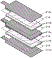
Fig. 21A, 21B, and 21C are diagrams illustrating a laminate-type secondary battery.
Fig. 22A and 22B are diagrams illustrating a laminate type secondary battery.
Fig. 23 is a view showing the external appearance of the secondary battery.
Fig. 24 is a view showing the external appearance of the secondary battery.
Fig. 25A, 25B, and 25C are diagrams for explaining a method of manufacturing a secondary battery.
Fig. 26A, 26B1, 26B2, 26C, and 26D are diagrams illustrating a bendable secondary battery.
Fig. 27A and 27B are diagrams illustrating a bendable secondary battery.
Fig. 28A, 28B, 28C, 28D, 28E, 28F, 28G, and 28H are diagrams illustrating an example of an electronic device.
Fig. 29A, 29B, and 29C are diagrams illustrating an example of an electronic device.
Fig. 30 is a diagram illustrating an example of an electronic device.
Fig. 31A, 31B, and 31C are diagrams illustrating an example of a vehicle.
Fig. 32 is a graph showing ESR measurement results.
Fig. 33 is a graph showing ESR measurement results.
Fig. 34A and 34B are diagrams illustrating spin densities.
Fig. 35A and 35B are graphs showing the relationship between the amount of magnesium added and the spin density.
Fig. 36 is a graph showing XRD measurement results.
Fig. 37A and 37B are diagrams showing XRD measurement results.
Fig. 38 is a graph showing XRD measurement results.
Fig. 39A and 39B are graphs showing lattice constants.
Fig. 40A and 40B are diagrams illustrating cycle characteristics.
Fig. 41A and 41B are diagrams illustrating cycle characteristics.
Fig. 42A and 42B are diagrams illustrating continuous charging characteristics.
Fig. 43A and 43B are graphs showing ESR measurement results.
Fig. 44A and 44B are graphs showing spin densities.
Fig. 45A and 45B are graphs showing the relationship between the amount of magnesium added and the spin density.
Fig. 46A and 46B are diagrams illustrating cycle characteristics.
Modes for carrying out the invention
Embodiments of the present invention will be described in detail below with reference to the drawings. Note that the present invention is not limited to the following description, and a person of ordinary skill in the art can easily understand the fact that the modes and details thereof can be changed into various forms. The present invention should not be construed as being limited to the description of the embodiments below.
In this specification and the like, the crystal plane and orientation are expressed by miller indices. Crystallographically, the numbers are underlined to indicate the crystallographic planes and orientations. However, in this specification and the like, due to the limitation of the symbols in the patent application, the crystal plane and orientation may be indicated by attaching a- (minus sign) to the front of the number instead of attaching a horizontal line to the number. In addition, the individual orientations showing the orientation within the crystal are represented by "[ ]", the collective orientations showing all equivalent crystal directions are represented by "< >", the individual faces showing the crystal faces are represented by "()", and the collective faces having equivalent symmetry are represented by "{ }".
In this specification and the like, segregation refers to a phenomenon in which a certain element (e.g., B) is spatially unevenly distributed in a solid containing a plurality of elements (e.g., A, B, C).
In the present specification and the like, the surface layer portion of the particle of the active material and the like means a region of about 10nm from the surface. The surface formed by the crack or the fissure may be referred to as a surface. The region deeper than the surface layer portion of the particle is referred to as the inside of the particle.
In the present specification and the like, the layered rock-salt type crystal structure of the composite oxide containing lithium and a transition metal means the following crystal structure: having a rock salt type ion arrangement in which cations and anions are alternately arranged, transition metals and lithium are regularly arranged to form a two-dimensional plane, in which lithium can be two-dimensionally diffused. Further, defects such as vacancies of cations or anions may be included. Strictly speaking, the layered rock salt type crystal structure is sometimes a structure in which the crystal lattice of the rock salt type crystal is deformed.
In this specification and the like, the rock salt type crystal structure refers to a structure in which cations and anions are alternately arranged. In addition, vacancies of cations or anions may also be included.
In this specification and the like, the pseudospinel crystal structure possessed by the composite oxide containing lithium and a transition metal means a space group R-3m, that is: although not a spinel-type crystal structure, ions of cobalt, magnesium, and the like occupy the oxygen hexacoordinate position, and the arrangement of cations has a crystal structure with symmetry similar to that of the spinel-type crystal structure. In addition, in a pseudo-spinel crystal structure, a light element such as lithium may occupy four-coordinate oxygen positions, and in this case, the arrangement of ions also has symmetry similar to that of a spinel crystal structure.
In addition, although the pseudospinel crystal structure contains lithium irregularly between layers, it may have a structure similar to CdCl2The crystal structure of the crystal is similar to that of the crystal structure of the crystal. The and CdCl2The crystal structure of the similar type is similar to that of lithium nickelate charged to a charge depth of 0.94 (Li)0.06NiO2) But a pure lithium cobaltate or a layered rock salt type positive electrode active material containing a large amount of cobalt generally does not have such a crystal structure.
The anions of the layered rock salt type crystal and the rock salt type crystal form a cubic closest packing structure (face centered cubic lattice structure), respectively. It is presumed that the anion in the pseudospinel type crystal also has a cubic closest packing structure. When these crystals are brought into contact, there are crystal faces of the cubic closest packing structure constituted by anions that are uniformly oriented. The layered rock-salt crystal and pseudospinel crystal have a space group of R-3m, which is different from the space group of the rock-salt crystal of Fm-3m (a space group of a general rock-salt crystal) and Fd-3m (a space group of a rock-salt crystal having the simplest symmetry), and therefore the crystalline planes of the layered rock-salt crystal and pseudospinel crystal satisfying the above conditions have different miller indices. In the present specification, in the layered rock-salt type crystal, the pseudospinel type crystal structure, and the rock-salt type crystal, the alignment of the cubic closest packing structure composed of anions may be substantially uniform in the crystal orientation.
The crystal orientations of the two regions can be judged to be approximately uniform from a Transmission Electron Microscope (TEM) image, a Scanning Transmission Electron Microscope (STEM) image, a High-angle Annular Dark-Scanning Transmission Electron microscope (HAADF-STEM: High-angle Annular Dark Field-Field-STEM) image, an Annular bright Field Scanning Transmission Electron microscope (ABF-STEM: Annular bright Field-STEM) image, and the like. In addition, X-ray diffraction (XRD), electron diffraction, neutron diffraction, or the like can be used as a criterion. In a TEM image or the like, the arrangement of cations and anions is observed as repetition of bright lines and dark lines. When the orientations of the cubic closest packed structure are aligned in the layered rock salt type crystal and the rock salt type crystal, an angle formed by repetition of the bright lines and the dark lines is observed to be 5 degrees or less, more preferably 2.5 degrees or less. Note that in a TEM image or the like, light elements such as oxygen and fluorine may not be clearly observed, and in this case, alignment of the orientation can be judged from the arrangement of the metal elements.
In the present specification and the like, the theoretical capacity of the positive electrode active material refers to an electric quantity at which all lithium capable of being intercalated and deintercalated in the positive electrode active material is deintercalated. For example, LiCoO2Has a theoretical capacity of 274mAh/g and LiNiO2Has a theoretical capacity of 274mAh/g and LiMn2O4The theoretical capacity of (a) is 148 mAh/g.
In this specification and the like, the depth of charge when all of the lithium capable of intercalation and deintercalation is intercalated is denoted by 0, and the depth of charge when all of the lithium capable of intercalation and deintercalation in the positive electrode active material is deintercalated is denoted by 1.
In this specification and the like, charging refers to moving lithium ions from a positive electrode to a negative electrode in a battery and moving electrons from the negative electrode to the positive electrode in an external circuit. The charging of the positive electrode active material refers to the desorption of lithium ions. In addition, a positive electrode active material having a depth of charge of 0.74 or more and 0.9 or less, more specifically, 0.8 or more and 0.83 or less is referred to as a high-voltage charged positive electrode active material. Thus, for example, when LiCoO2It was said that the positive electrode active material was charged at a high voltage when charged to 219.2 mAh/g. In addition, LiCoO is as follows2Positive electrode active material also charged by high voltage: LiCoO which is subjected to constant-current charging at a charging voltage of 4.525V or more and 4.65V or less (in the case where the electrode is lithium) in an environment of 25 ℃, and then subjected to constant-voltage charging so that the current value becomes 0.01C or 1/5 to 1/100 or so of the current value during constant-current charging2。
Similarly, discharging refers to moving lithium ions from the negative electrode to the positive electrode in the battery and moving electrons from the positive electrode to the negative electrode in an external circuit. The discharge of the positive electrode active material refers to the insertion of lithium ions. In addition, the charging depth is adjustedA positive electrode active material that is 0.06 or less or a positive electrode active material that has been discharged from a state of having been charged at a high voltage to a capacity of 90% or more of the charge capacity is referred to as a fully discharged positive electrode active material. For example, in LiCoO2The middle charge capacity of 219.2mAh/g means a state of being charged with a high voltage, and the positive electrode active material after discharging 90% or more of the charge capacity at 197.3mAh/g from this state is a sufficiently discharged positive electrode active material. In addition, it will be in LiCoO2The positive electrode active material after constant current discharge is performed until the battery voltage becomes 3V or less (when the electrode lithium is charged) in an environment of 25 ℃ is also referred to as a sufficiently discharged positive electrode active material.
In this specification and the like, the nonequilibrium transformation refers to a phenomenon that causes a nonlinear change in a physical quantity. For example, an unbalanced phase transition may occur near a peak of a dQ/dV curve obtained by differentiating (dQ/dV) a capacity (Q) and a voltage (V), and a crystal structure may be largely changed.
(embodiment mode 1)
In this embodiment, a positive electrode active material according to one embodiment of the present invention will be described.
One embodiment of the present invention is a positive electrode active material containing lithium, cobalt, and oxygen. The positive electrode active material according to one embodiment of the present invention preferably further contains magnesium. Since the crystal structure is stable due to the inclusion of magnesium, collapse of the crystal structure when charge and discharge are repeated can be suppressed. The positive electrode active material according to one embodiment of the present invention is lithium cobaltate (LiCoO)2) Part of Li+Is coated with Mg2+By substitution of, thereby, Co in the vicinity thereof3+Is reduced to Co2+(see fig. 1A and 2A). In addition, a part of Co3+Is coated with Mg2+By substitution of, thereby, Co in the vicinity thereof3+Is oxidized to Co4+(see fig. 1B and 2A). Therefore, the positive electrode active material according to one embodiment of the present invention contains Co2+And Co4+One or both. The positive electrode active material is derived from Co per unit weight2+And Co4+Spin density of (2) is preferably 2.0X 10171.0X 10 of seeds/g or more18The spis/g is less than or equal to. Through the positive electrode active materialWith the above spin density, the crystal structure is stable particularly in the charged state, which is preferable. Note that fig. 2A is a schematic diagram illustrating the structure of a positive electrode active material containing no magnesium, and fig. 1A and 1B are schematic diagrams illustrating the structure of a positive electrode active material containing magnesium according to an embodiment of the present invention. In addition, when the amount of magnesium added is too large, Co may be the cause2+And Co4 +The spin density of (2B) is decreased (see fig. 2B). In addition, when the positive electrode active material according to one embodiment of the present invention is used for a secondary battery, a secondary battery having excellent cycle characteristics and rate characteristics can be realized.
The magnesium concentration in the positive electrode active material is preferably 0.1 atomic% or more and 6.0 atomic% or less, more preferably 0.5 atomic% or more and 5.0 atomic% or less, and still more preferably 1.0 atomic% or more and 4.0 atomic% or less, with respect to cobalt atoms. Note that the magnesium concentration is an average value of the entire particles of the positive electrode active material.
For example, the Spin density in the positive electrode active material can be analyzed by using an Electron Spin Resonance method (ESR) or the like. The average magnesium concentration of the entire particles of the positive electrode active material can be analyzed by, for example, Inductively Coupled Plasma Mass Spectrometry (ICP-MS).
The positive electrode active material according to one embodiment of the present invention preferably further contains fluorine. By containing fluorine, the corrosion resistance to hydrofluoric acid generated by decomposition of the electrolyte can be improved. For example, the composition of the positive electrode active material is measured by using X-ray Photoelectron Spectroscopy (XPS: X-ray photon Spectroscopy) or the like. In addition, for example, inductively coupled plasma mass spectrometry (ICP-MS) or the like can analyze the average value of the fluorine concentration of the entire particles of the positive electrode active material.
The lattice constant of the a-axis of the positive electrode active material according to one embodiment of the present invention is preferably 2.8155 × 10⁻¹⁰m is greater than or equal to 2.8175 multiplied by 10-10The lattice constant of m and c axes is preferably 14.045 × 10⁻¹⁰m is greater than or equal to 14.065 multiplied by 10-10m is less than or equal to m.
[ Structure of Positive electrode active Material ]
A positive electrode active material 100 according to one embodiment of the present invention, a conventional positive electrode active material, and a difference therebetween will be described with reference to fig. 3 and 4. Fig. 3 and 4 illustrate a case where cobalt is used as the transition metal contained in the positive electrode active material. Fig. 3 shows a positive electrode active material 100 according to an embodiment of the present invention. Fig. 4 shows a conventional positive electrode active material. Note that the conventional positive electrode active material illustrated in fig. 4 is simple lithium cobaltate (LiCoO)2) Wherein elements other than lithium, cobalt, and oxygen are not added to the inside of the positive electrode active material, and the surface layer portion of the particles of the positive electrode active material is not coated with elements other than lithium, cobalt, and oxygen.
< conventional Positive electrode active Material >
Lithium cobaltate LiCoO, one of conventional positive electrode active materials2As described in non-patent document 1, non-patent document 2, and the like, the crystal structure changes depending on the depth of charge. Fig. 4 shows a crystal structure showing a typical lithium cobaltate.
As shown in FIG. 4, lithium cobaltate whose charge depth is 0 (discharge state) includes a region having a crystal structure of space group R-3m and includes three CoOs in a unit cell2And (3) a layer. This crystal structure is sometimes referred to as O3 type crystal structure. Note that CoO2The layer is a structure in which an octahedral structure formed by cobalt and six coordinated oxygens maintains a state in which ridges are shared on one plane.
When the depth of charge is 1, has a crystal structure of space group P-3m1, and the unit cell comprises a CoO2And (3) a layer. This crystal structure is sometimes referred to as O1 type crystal structure.
When the depth of charge is about 0.88, lithium cobaltate has a crystal structure of space group R-3m, and the structure can be said to be CoO such as P-3m1(O1)2LiCoO with a structure similar to that of R-3m (O3)2The structures are alternately stacked. Thus, this crystal structure is sometimes referred to as H1-3 type crystal structure. In fact, the number of cobalt atoms in each unit cell of the H1-3 type crystal structure is 2 times that of the other structures. However, in this specification such as FIG. 4, 1/2 of unit cell is used for easy comparison with other structuresThe formula represents the c-axis in the H1-3 type crystal structure.
When charging and discharging of a high voltage having a charge depth of about 0.88 or more are repeated, the crystal structure of lithium cobaltate is repeatedly changed (i.e., nonequilibrium phase transition) between the H1-3 type crystal structure and the structure of R-3m (O3) in a discharged state.
However, CoO of the above two crystal structures2The deviation of the layer is large. As shown by the dotted line and double arrow in FIG. 4, CoO is present in the H1-3 crystal structure2The layers deviate significantly from R-3m (O3). Such dynamic structural changes can adversely affect the stability of the crystalline structure.
Further, the volume difference between the H1-3 type crystal structure and the O3 type crystal structure is also large. The difference in volume between the H1-3 type crystal structure and the O3 type crystal structure in a discharged state is 3.5% or more per the same number of cobalt atoms.
In addition to the above, the H1-3 type crystal structure has a CoO such as P-3m1(O1)2The possibility of the structure of the layer continuity being unstable is high.
As a result, the crystal structure of lithium cobaltate collapses when high-voltage charge and discharge are repeated. And collapse of the crystal structure causes deterioration of cycle characteristics. This is because the sites where lithium can stably exist are reduced due to collapse of the crystal structure, and thus, insertion and desorption of lithium become difficult.
< Positive electrode active Material according to one embodiment of the present invention >
< interior of particle >
The positive electrode active material 100 according to one embodiment of the present invention has a small change in crystal structure and a small volume difference from the same number of transition metal atoms in a fully discharged state and a high-voltage charged state (a charged depth of 0.8 to 0.83).
Fig. 3 shows the crystal structure of the positive electrode active material 100 before and after charge and discharge. The positive electrode active material 100 according to one embodiment of the present invention is a composite oxide containing lithium and cobalt. Preferably, magnesium is contained in addition to the above. Further, it is preferable that the resin composition further contains a halogen such as fluorine or chlorine.
Charging depth shown in fig. 3The crystal structure at degree 0 (discharge state) is R-3m (O3) as in FIG. 4. On the other hand, when the fully charged charge depth is about 0.88, the positive electrode active material 100 according to one embodiment of the present invention has a crystal structure different from that of fig. 4. In the present description, the crystal structure of the space group R-3m is referred to as a pseudospinel crystal structure. In addition, in order to explain the symmetry of cobalt atoms and the symmetry of oxygen atoms, lithium is not shown in the diagram of the pseudo-spinel crystal structure shown in FIG. 3, but CoO is actually used2Lithium is present between the layers at about 12 atomic% relative to cobalt. In both of the O3 type crystal structure and the pseudo-spinel type crystal structure, CoO is preferable2A small amount of magnesium is present between the layers, i.e. at the lithium sites. In addition, it is preferable that a halogen such as fluorine is irregularly present at the oxygen site.
In the positive electrode active material 100, the material is compatible with conventional LiCoO2In contrast, the change in crystal structure when a large amount of lithium is desorbed during high-voltage charging is suppressed. For example, as shown by the dotted line in FIG. 3, there is almost no CoO in the above crystal structure2Deviation of the layers.
In the positive electrode active material 100, the difference in volume between each unit cell of the O3 type crystal structure having a charge depth of 0 and the pseudo-spinel type crystal structure having a charge depth of 0.88 is 2.5% or less, specifically 2.2% or less.
Thus, the crystal structure of the positive electrode active material 100 is not easily collapsed even when charge and discharge are repeated at a high voltage.
The coordinates of cobalt and oxygen in each unit cell of the pseudospinel crystal structure can be represented by Co (0,0,0.5), O (0,0, x) (0.20. ltoreq. x.ltoreq.0.25), respectively.
In CoO2The presence of magnesium in small amounts irregularly between layers (i.e., lithium sites) has the effect of inhibiting CoO2The effect of the deflection of the layer. Thereby when in CoO2A pseudospinel crystal structure is readily obtained when magnesium is present between the layers. In addition, it is preferable that magnesium is distributed throughout the particles of the positive electrode active material 100. In order to distribute magnesium throughout the particles, it is preferable to perform a heat treatment in the process of producing the positive electrode active material 100.
However, when the temperature of the heat treatment is too high, cation mixing (cation mixing) occurs, and the possibility of magnesium entering the cobalt site increases. When magnesium is present at the cobalt site, the effect of maintaining R-3m is sometimes reduced. Further, when the heat treatment temperature is too high, there is a possibility that adverse effects such as instability of the layered rock salt type structure and lithium evaporation occur.
Therefore, it is preferable to add a halogen compound such as a fluorine compound to the lithium cobaltate before performing the heat treatment for distributing magnesium throughout the particles. The melting point of lithium cobaltate was lowered by adding the halogen compound. By lowering the melting point, magnesium can be easily distributed throughout the particles at a temperature at which cation-mixing is less likely to occur. Here, the positive electrode active material may be corroded by hydrofluoric acid generated by decomposition of the electrolyte. Since the positive electrode active material 100 according to one embodiment of the present invention contains fluorine, the corrosion resistance to hydrofluoric acid generated by decomposition of the electrolyte can be improved.
Note that in this specification and the like, the electrolyte refers to a substance having conductivity. The electrolyte is not limited to a liquid, and may be a gel or a solid. A liquid electrolyte is sometimes referred to as an electrolytic solution, and the electrolytic solution can be produced by dissolving a solute in a solvent. In addition, a solid electrolyte is sometimes referred to as a solid electrolyte.
Note that, although the case where the positive electrode active material 100 is a composite oxide containing lithium, cobalt, and oxygen has been described above, nickel may be contained in addition to cobalt. In this case, the ratio Ni/(Co + Ni) of the number of atoms of cobalt to the number of atoms of nickel (Ni) in the sum (Co + Ni) is preferably less than 0.1, and more preferably 0.075 or less.
When the high-voltage charged state is maintained for a long time, the transition metal in the positive electrode active material dissolves in the electrolytic solution, and the crystal structure may be deformed. However, by containing nickel in the above ratio, the dissolution of the transition metal in the positive electrode active material 100 may be suppressed.
By adding nickel, the charging and discharging voltage is reduced, and therefore, charging and discharging can be performed at a lower voltage with the same capacity. This can suppress dissolution of the transition metal and decomposition of the electrolyte. Here, the charge and discharge voltage refers to, for example, a voltage in a range from a charge depth 0 to a predetermined charge depth.
< surface layer part of particle >
The magnesium is preferably distributed throughout the particles of the positive electrode active material 100, but in addition to this, the magnesium concentration in the surface layer portion of the particles is preferably higher than the average of the entire particles. The magnesium concentration in the surface layer portion of the particle can be measured by X-ray photoelectron spectroscopy (XPS) or the like, for example. For example, the average magnesium concentration of the entire particle can be measured by inductively coupled plasma Mass Spectrometry (ICP-MS), Glow Discharge Mass Spectrometry (GDMS), or the like. The surface of the particles is a crystal defect and the lithium concentration at the surface is lower than that in the interior of the particles because lithium is desorbed from the surface of the particles during charging. Therefore, the particle surface tends to be unstable and the crystal structure is easily broken. When the magnesium concentration in the surface layer portion of the particle is high, the change in the crystal structure can be more effectively suppressed. Further, when the magnesium concentration in the surface layer portion of the particles is high, it is expected that the corrosion resistance to hydrofluoric acid generated by decomposition of the electrolytic solution is improved.
Preferably, the concentration of halogen such as fluorine in the surface layer portion of the particles of the positive electrode active material 100 is higher than the average concentration of the entire particles. The corrosion resistance to hydrofluoric acid can be effectively improved by the halogen present in the particle surface portion of the region in contact with the electrolytic solution.
Thus, it is preferred that: the positive electrode active material 100 has a higher concentration of magnesium and fluorine in the surface layer portion of the particles than in the interior of the particles; having a different composition than the interior of the particle. The composition of the surface layer portion of the particle is preferably a crystal structure stable at room temperature. Thus, the surface layer portion of the particle may have a different crystal structure from the inside of the particle. For example, at least a part of the particle surface layer portion of the positive electrode active material 100 may have a rock-salt type crystal structure. Note that when the surface layer portion of the particle has a crystal structure different from that of the inside of the particle, the orientations of the crystals in the surface layer portion of the particle and the inside of the particle are preferably substantially the same.
However, when the surface layer portion of the particle has a structure in which only MgO or only MgO and coo (ii) are in solid solution, lithium is hardly inserted and detached. Therefore, the surface layer portion of the particle needs to contain at least cobalt, and lithium is contained during discharge so as to have a path for lithium insertion and desorption. In addition, the concentration of cobalt is preferably higher than that of magnesium.
< grain boundary >
The magnesium or halogen contained in the positive electrode active material 100 may be present in the inside of the particles in an irregular and small amount, but it is more preferable that a part thereof segregates in the grain boundary.
In other words, the magnesium concentration in the grain boundary and the vicinity thereof of the positive electrode active material 100 is preferably higher than in other regions inside the particles. In addition, the halogen concentration in the grain boundary and the vicinity thereof is preferably higher than that in other regions inside.
Grain boundaries are also surface defects, as are particle surfaces. This makes the grain boundary unstable and the crystal structure easily starts to change. Thus, when the magnesium concentration in the grain boundary and the vicinity thereof is high, the change in the crystal structure can be more effectively suppressed.
In addition, when the concentrations of magnesium and halogen are high at and near the grain boundaries, even when cracks are generated along the grain boundaries of the particles of the positive electrode active material 100, the concentrations of magnesium and halogen are high near the surfaces where the cracks are generated. It is therefore possible to improve the corrosion resistance to hydrofluoric acid of the positive electrode active material after crack generation.
Note that in this specification and the like, the vicinity of the grain boundary refers to a region ranging from the grain boundary to about 10 nm.
< particle size >
When the particle size of the positive electrode active material 100 is too large, the following problems occur: diffusion of lithium becomes difficult; the surface of the active material layer is excessively rough when coated on the current collector. On the other hand, when the particle diameter of the positive electrode active material 100 is too small, the following problems occur: the active material layer is not easy to be supported when the current collector is coated; excessive reaction with the electrolyte, etc. Therefore, the average particle diameter (D50) is preferably 1 μm or more and 100 μm or less, more preferably 2 μm or more and 40 μm or less, and still more preferably 5 μm or more and 30 μm or less.
In the present specification and the like, the average particle diameter (D50) is a cumulative 50% particle diameter based on the volume. The average particle diameter (D50) is sometimes referred to as the median particle diameter.
< analytical method >
In order to determine whether or not a certain positive electrode active material is the positive electrode active material 100 according to one embodiment of the present invention showing a pseudo-spinel crystal structure when charged at a high voltage, the positive electrode charged at a high voltage may be determined by analysis using XRD, Electron diffraction, neutron diffraction, Electron Spin Resonance (ESR), Nuclear Magnetic Resonance (NMR), magnetization measurement, or the like. In particular, XRD has the following advantages, and is therefore preferable: the symmetry of the transition metal such as cobalt contained in the positive electrode active material can be analyzed with high resolution; the degree of crystallinity can be compared with the orientation of the crystals; the periodic distortion and the grain size of the crystal lattice can be analyzed; sufficient accuracy and the like can be obtained also when the positive electrode obtained by disassembling the secondary battery is directly measured.
As described above, the positive electrode active material 100 according to one embodiment of the present invention is characterized in that: the crystal structure between the high-voltage charged state and the discharged state is less changed. A material having a crystal structure which largely changes between charging and discharging at high voltage of 50 wt% or more is not preferable because it cannot withstand high-voltage charging and discharging. Note that a desired crystal structure may not be achieved by adding only elements. For example, a positive electrode active material of lithium cobaltate containing magnesium and fluorine may have a pseudospinel crystal structure of 60 wt% or more, and may have an H1-3 crystal structure of 50 wt% or more, in a state of being charged at a high voltage. Further, the pseudospinel crystal structure becomes almost 100 wt% when a predetermined voltage is applied, and the H1-3 type crystal structure is sometimes generated when the predetermined voltage is further increased. Accordingly, when determining whether or not the positive electrode active material 100 is one embodiment of the present invention, it is necessary to analyze the crystal structure by XRD or the like.
However, the crystal structure of the positive electrode active material in a high-voltage charged state or discharged state may change when exposed to air. For example, the crystal structure is sometimes changed from a pseudospinel type crystal structure to an H1-3 type crystal structure. Therefore, all samples are preferably treated in an inert atmosphere such as an argon atmosphere.
< charging method >
As the high-voltage charging of the positive electrode active material 100 for determining whether or not a certain composite oxide is an embodiment of the present invention, for example, a coin battery (CR2032 type, 20mm in diameter and 3.2mm in height) using lithium as a counter electrode can be manufactured and charged.
More specifically, a positive electrode obtained by coating a positive electrode current collector made of aluminum foil with a slurry obtained by mixing a positive electrode active material, a conductive auxiliary agent, and a binder can be used as the positive electrode.
As the counter electrode, lithium metal may be used. Note that the potential of the positive electrode when a material other than lithium metal is used as the counter electrode is different from that of the secondary battery. Unless otherwise specified, the voltage and potential in this specification and the like are potentials of the positive electrode.
As an electrolyte contained in the electrolyte solution, 1mol/L lithium hexafluorophosphate (LiPF) was used6). As the solvent, a solvent prepared by mixing 3: 7 Ethylene Carbonate (EC), diethyl carbonate (DEC) and 2 wt% Vinylene Carbonate (VC).
As the separator, polypropylene having a thickness of 25 μm can be used.
The positive electrode can and the negative electrode can may be formed of stainless steel (SUS).
The coin cell manufactured under the above conditions was subjected to constant current charging at 4.6V and 0.5C, and then constant voltage charging was continued until the current value became 0.01C. Here, 1C was set to 137 mA/g. The temperature was set to 25 ℃. By detaching the coin cell in the glove box under an argon atmosphere after charging as described above and taking out the positive electrode, a positive electrode active material charged with a high voltage can be obtained. When various analyses are performed later, sealing is preferably performed under an argon atmosphere in order to prevent reaction with external components. For example, XRD can be performed under the condition of a sealed vessel enclosed in an argon atmosphere.
<XRD>
Fig. 5 shows an ideal powder XRD pattern expressed as CuK α 1 line calculated from a model of a pseudospinel type crystal structure and a H1-3 type crystal structure. For comparison, LiCoO with a charging depth of 0 is also shown2(O3) and CoO with a depth of charge of 12(O1) crystal structure. LiCoO2(O3) and CoO2The pattern of (O1) was calculated from Crystal Structure information obtained from ICSD (Inorganic Crystal Structure Database) (see non-patent document 5) using a Reflex Powder Diffraction which is one of the modules of Materials Studio (BIOVIA). The range of 2 θ is set to 15 ° to 75 °, Step size 0.01, and wavelength λ 1 1.540562 × 10⁻¹⁰m,. lamda.2 is not set, and Monochromyator is set to single. The pattern of the H1-3 type crystal structure was prepared in the same manner with reference to the crystal structure information described in non-patent document 3. A pattern of a pseudospinel crystal structure is produced by the following method: the XRD pattern of the positive electrode active material according to one embodiment of the present invention was estimated and fitted with TOPAS ver.3 (crystal structure analysis software manufactured by Bruker corporation), and the XRD pattern was prepared in the same manner as other structures.
As shown in fig. 5, in the pseudospinel-type crystal structure, diffraction peaks appear at 19.30 ± 0.20 ° (19.10 ° or more and 19.50 ° or less) of 2 θ and at 45.55 ± 0.10 ° (45.45 ° or more and 45.65 ° or less) of 2 θ. More specifically, sharp diffraction peaks appear at 19.30 ± 0.10 ° (19.20 ° or more and 19.40 ° or less) in 2 θ and at 45.55 ± 0.05 ° (45.50 ° or more and 45.60 ° or less) in 2 θ. However, H1-3 type crystal structure and CoO2(P-3m1, O1) showed no peak at the above position. From this, it can be said that the positive electrode active material 100 according to one embodiment of the present invention is characterized by peaks at 19.28 ± 0.60 ° 2 θ and 45.55 ± 0.20 ° 2 θ in a state of being charged with a high voltage.
It can be said that the crystal structure having a charge depth of 0 is close to the position of the diffraction peak observed by XRD of the crystal structure at the time of high-voltage charge. More specifically, the difference in the positions of two or more, preferably three or more, of the two main diffraction peaks is 0.7 or less, more preferably 0.5 or less, as 2 θ.
Note that the positive electrode active material 100 according to one embodiment of the present invention has a pseudo-spinel crystal structure when charged at a high voltage, but all the particles are not necessarily required to have a pseudo-spinel crystal structure. The crystal structure may be other, and a part of the crystal structure may be amorphous. Note that when the XRD pattern is subjected to the rietveld analysis, the pseudospinel crystal structure is preferably 50 wt% or more, more preferably 60 wt% or more, and further preferably 66 wt% or more. When the pseudospinel crystal structure is 50 wt% or more, more preferably 60 wt% or more, and still more preferably 66 wt% or more, a positive electrode active material having sufficiently excellent cycle characteristics can be realized.
The pseudospinel crystal structure by the Ritveld analysis after 100 or more charge/discharge cycles from the start of the measurement is preferably 35 wt% or more, more preferably 40 wt% or more, and still more preferably 43 wt% or more.
LiCoO in which the particle size of the positive electrode active material particles having a pseudospinel crystal structure is reduced to only a discharge state2(O3) about 1/10. Thus, even under the same XRD measurement conditions as those of the positive electrode before charge and discharge, a sharp peak of a pseudospinel crystal structure was observed after high-voltage charge. On the other hand, even simple LiCoO2Some of them may have a structure similar to a pseudospinel crystal structure, and the crystal grain size may be small and the peak thereof may be broad and small. The grain size can be determined from the half-width value of the XRD peak.
The lattice constant of the c-axis in the layered rock salt crystal structure of the particles of the positive electrode active material in the discharge state that can be estimated from the XRD pattern is preferably small. The lattice constant of the c-axis becomes large when the position of lithium is substituted by a foreign element (foreign element) or cobalt enters an oxygen four-coordinate position (a position), or the like. Therefore, first, Co having a substitution of a foreign element and a spinel-type crystal structure is produced3O4A positive electrode active material having good cycle characteristics can be produced by mixing a layered rock salt type composite oxide having a small number of defects (i.e., a small number of defects) with a magnesium source and a fluorine source to allow magnesium to be inserted into lithium sites.
The lattice constant of the a-axis in the crystal structure of the positive electrode active material in the discharge state is preferably 2.8155 × 10⁻¹⁰m is greater than or equal to 2.8175 multiplied by 10-10m, and the lattice constant of the c-axis is preferablyIs 14.045X 10⁻¹⁰m is greater than or equal to 14.065 multiplied by 10-10m is less than or equal to m.
In order to set the lattice constant of the c-axis within the above range, it is preferable that the amount of impurities is small, and particularly, it is preferable that the amount of transition metals other than cobalt, manganese, and nickel is small. Specifically, 3000ppm (wt) or less is preferable, and 1500ppm (wt) or less is more preferable. Further, it is preferable that the mixing of lithium with cations of cobalt, manganese, and nickel is small.
From the XRD pattern, characteristics regarding the internal structure of the positive electrode active material were known. In the positive electrode active material having an average particle diameter (D50) of about 1 μm to 100 μm, the volume of the particle surface layer portion is very small compared to the inside, and therefore, even if the particle surface layer portion of the positive electrode active material 100 has a crystal structure different from that of the inside of the particle, there is a possibility that the XRD pattern is not exhibited.
<ESR>
Here, a case where the difference between the pseudo-spinel crystal structure and the other crystal structures is determined by ESR will be described with reference to fig. 6 and 7. As shown in fig. 3 and 6A, cobalt is present at the position of oxygen hexacoordination. As shown in FIG. 6B, in oxygen hexacoordinated cobalt, the 3d orbital splits into egTrack and t2gA track. In cobalt hexa-coordinated with oxygen, e of an orbital arranged in the direction in which oxygen existsgT arranged avoiding the direction of oxygen existence in the orbit2gThe energy of the track is low, and t2gThe rail is in the ground state. A part of the cobalt present at the position of oxygen hexacoordination is Co3+Co in the ground state3+Is t2gDiamagnetic Co with filled-in tracks3+(spin quantum number S ═ 0). The other part of the cobalt present at the position of oxygen hexacoordination may also be Co2+Or Co4+Co in the ground state2+Or Co4+Is paramagnetic (spin quantum number S-1/2). The above paramagnetic Co2+Or Co4+Since all cobalt (iii) of (iii) includes one (spin quantum number S: 1/2) unpaired electron, it cannot be determined by ESR.
On the other hand, it is described that some of conventional positive electrode active materials may have a spinel crystal structure in which the particle surface layer portion does not contain lithium in a charged state. At this time, the toolCo having a spinel-type crystal structure shown in FIG. 7A3O4。
In the general formula A [ B ]2]O4When the spinel is represented, the element A is in oxygen four-coordination, and the element B is in oxygen six-coordination. In this specification and the like, the position where oxygen is tetracoordinated is sometimes referred to as the a position, and the position where oxygen is hexacoordinated is sometimes referred to as the B position.
Co in spinel crystal structure3O4In the cobalt (A), cobalt is present at the oxygen tetracoordinate A site in addition to the oxygen hexacoordinate B site. As shown in FIG. 7B, e is formed by splitting in the 3d orbital of cobalt tetradentate with oxygengTrack and t2gIn the track, egLow energy of the track and egThe rail is in the ground state. Whereby Co is tetracoordinated to oxygen2+、Co3+And Co4+In the ground state, both include unpaired electrons and are paramagnetic. Thus, when precipitated by ESR or the like, spinel-type Co is sufficiently contained3O4When the particles of (2) are used, paramagnetic Co caused by oxygen tetradentate is surely detected2+(spin quantum number S. 3/2), Co3+(spin quantum number S ═ 1) or Co4+(spin quantum number S-1/2).
However, the signal due to the paramagnetic cobalt tetradentate with oxygen of the positive electrode active material 100 according to one embodiment of the present invention is too small to be confirmed. Therefore, the pseudospinel crystal structure in the present specification and the like does not contain cobalt tetracoordinated with oxygen in an amount detectable by ESR, unlike the spinel crystal structure. Therefore, the positive electrode active material 100 according to one embodiment of the present invention may be detected by ESR or the like, which is caused by spinel-type Co, as compared with conventional positive electrode active materials3O4Is small or too small to be confirmed. Due to spinel type Co3O4Does not contribute to charge-discharge reaction, so spinel type Co3O4The less the better. As described above, the positive electrode active material 100 can be determined to be different from conventional positive electrode active materials by ESR analysis.
The positive electrode active material according to one embodiment of the present invention contains Co2+And Co4+One or both. In addition, the bookThe positive electrode active material according to one embodiment of the present invention is derived from Co2+And Co4+Spin density of (2) is preferably 2.0X 10171.0X 10 of seeds/g or more18The ratio of spis to g is preferably 2.5X 10¹⁷spis/g or more and 9.5X 10¹⁷The ratio of spis/g or less, more preferably 3.0X 10¹⁷spis/g or more and 9.0X 10¹⁷The ratio of spis/g is preferably 3.5X 10¹⁷spin/g or more and 8.5X 10¹⁷The spis/g is less than or equal to. For example, the spin density of the positive electrode active material can be evaluated by ESR analysis. Furthermore, it is due to Co2+And Co4+The g value of the ESR signal of (2) was observed to be around 2.15. The spin density is a value obtained by ESR analysis at room temperature, and is the number of spins per unit weight of the positive electrode active material. The spin density can be calculated by dividing the number of spins obtained by ESR analysis by the weight of the sample used for ESR analysis.
The positive electrode active material according to one embodiment of the present invention is derived from Co2+And Co4+Spin density of (3) is preferably 3.3X 10-51.6X 10 and not less than spins/Co atom-4A spin/Co atom or less, more preferably 4.1X 10-51.5X 10 and not less than spins/Co atom-4A ratio of spins/Co atoms or less, more preferably 4.9X 10-51.5X 10 and not less than spins/Co atom- 4The ratio of spis to Co is preferably 5.7X 10-51.4X 10 of spins/Co atom or more-4The spins/Co atom is less than or equal to. The spin density is a value obtained by ESR analysis at room temperature, and is the number of spins per cobalt atom of the positive electrode active material. The spin density can be calculated by dividing the number of spins obtained by ESR analysis by the number of cobalt atoms in the positive electrode active material used for ESR analysis. For example, in the case of lithium cobaltate, the composition is LiCoO2The number of cobalt atoms in the positive electrode active material was calculated from the molecular weight of 97.87 and the weight of the positive electrode active material used for ESR analysis.
The positive electrode active material having the spin density has a stable crystal structure, and can suppress the crystal structure from collapsing during repeated charge and discharge. In addition, when the positive electrode active material according to one embodiment of the present invention is used for a secondary battery, a secondary battery having excellent cycle characteristics and rate characteristics can be realized. In addition, the positive electrode active material having the spin density may have a pseudospinel crystal structure in a charged state.
<XPS>
Since X-ray photoelectron spectroscopy (XPS) can analyze a depth range from the surface to about 2nm to 8nm (generally about 5 nm), the concentration of each element in about half of the surface layer of the particle can be quantitatively analyzed. In addition, by performing narrow scan analysis, the bonding state of the elements can be analyzed. The measurement accuracy of XPS is about ± 1 atomic% in many cases, and the lower limit of detection is about 1 atomic% depending on the element.
When XPS analysis of the positive electrode active material 100 is performed, the relative value of the magnesium concentration when the cobalt concentration is 1 is preferably 0.4 or more and 1.5 or less, and more preferably 0.45 or more and less than 1.00. The relative value of the halogen concentration such as fluorine is preferably 0.05 or more and 1.5 or less, and more preferably 0.3 or more and 1.00 or less.
When the positive electrode active material 100 is analyzed by XPS, the peak of the bonding energy between fluorine and another element is preferably 682eV or more and less than 685eV, and more preferably about 684.3 eV. This value differs from 685eV, which is the bonding energy of lithium fluoride, and 686eV, which is the bonding energy of magnesium fluoride. In other words, when the positive electrode active material 100 contains fluorine, a bond other than lithium fluoride and magnesium fluoride is preferable.
When XPS analysis of the positive electrode active material 100 is performed, the peak of the bonding energy between magnesium and another element is preferably 1302eV or more and less than 1304eV, and more preferably 1303eV or so. This value is different from the 1305eV of the bonding energy of magnesium fluoride and is close to that of magnesium oxide. In other words, when the positive electrode active material 100 contains magnesium, the bonding is preferably other than magnesium fluoride.
<EDX>
For example, the concentrations of various elements in the interior of the particles, in the surface layer portion of the particles, and in the vicinity of the grain boundary can be evaluated by Energy Dispersive X-ray Spectroscopy (EDX). In EDX measurement, a method of measuring the inside of a region while scanning and performing two-dimensional evaluation of the inside of the region is sometimes called EDX plane analysis. In addition, a method of extracting data of a linear region from the surface analysis of EDX and evaluating the atomic concentration distribution in the positive electrode active material particles is sometimes referred to as line analysis.
The concentrations of magnesium and fluorine in the interior of the particles, in the surface layer portion of the particles, and in the vicinity of the grain boundaries can be quantitatively analyzed by EDX surface analysis (e.g., elemental mapping). Further, the EDX ray analysis can analyze peaks of the concentrations of magnesium and fluorine.
In EDX analysis of the positive electrode active material 100, the peak concentration of magnesium in the surface layer portion of the particles preferably occurs in a range of 3nm in depth from the surface of the positive electrode active material 100 to the center, more preferably in a range of 1nm in depth, and still more preferably in a range of 0.5nm in depth.
The fluorine distribution of the positive electrode active material 100 preferably overlaps with the magnesium distribution. Therefore, in the EDX analysis, the concentration peak of fluorine in the surface layer portion of the particle preferably occurs in a range of a depth of 3nm from the surface of the positive electrode active material 100 to the center, more preferably in a range of a depth of 1nm, and further preferably in a range of a depth of 0.5 nm.
When the line analysis or the surface analysis of the positive electrode active material 100 is performed, the atomic number ratio (Mg/Co) of magnesium and cobalt in the vicinity of the grain boundary is preferably 0.020 or more and 0.50 or less. More preferably 0.025 or more and 0.30 or less. More preferably 0.030 to 0.20.
< dQ/dVvsV curve >
The positive electrode active material according to one embodiment of the present invention exhibits a characteristic voltage change immediately after completion of discharge when the positive electrode active material is charged at a high voltage and then discharged at a low rate of, for example, 0.2C or less. This voltage change can be clearly observed when at least one peak in the dQ/dVvsV curve calculated from the discharge curve lies in the range of 3.5V to 3.9V.
(embodiment mode 2)
In this embodiment, an example of a method for producing a positive electrode active material according to an embodiment of the present invention is described.
[ method 1 for producing Positive electrode active Material ]
An example of a method for producing the positive electrode active material 100 according to one embodiment of the present invention will be described with reference to fig. 8 and 9.
< step S11>
In step S11, a halogen source and a magnesium source are prepared as materials of the first mixture (step S11 in fig. 8 and 9). Preferably, a lithium source is also prepared. In addition, when the subsequent mixing and pulverizing steps are performed by a wet method, a solvent is prepared.
Examples of the magnesium source include magnesium fluoride, magnesium oxide hydrate, and magnesium carbonate. As the lithium source, for example, lithium fluoride and lithium carbonate can be used.
As the halogen source, a material containing fluorine, chlorine, or the like can be used. A material containing halogen and magnesium may be used as the halogen source and the magnesium source. In addition, a material containing halogen and lithium may be used as the halogen source and the lithium source. As the halogen source and the lithium source containing fluorine, for example, lithium fluoride or the like can be used. As the halogen source and magnesium source containing fluorine, for example, magnesium fluoride or the like can be used. Among these, lithium fluoride is preferably used as a halogen source and a lithium source because it has a low melting point of 848 ℃ and is easily melted in an annealing step described later. As the halogen source and the lithium source containing chlorine, for example, lithium chloride can be used. Examples of the halogen source and magnesium source containing chlorine include magnesium chloride.
As the solvent, ketones such as acetone, alcohols such as ethanol and isopropanol, diethyl ether, dioxane, acetonitrile, N-methyl-2-pyrrolidone (NMP), and the like can be used. An aprotic solvent which does not readily react with lithium is preferably used, and acetone, for example, can be preferably used.
Examples of the halogen source and the lithium source include lithium fluoride (LiF), and magnesium fluoride (MgF) is used as the halogen source and the magnesium source2) The example of (2) will be specifically described. When lithium fluoride and magnesium fluoride are expressed as LiF: MgF265: about 35 (molar ratio) is most effective for lowering the melting point (non-patent document 4). When the amount of lithium fluoride is large, lithium becomes too much to possibly cause deterioration of cycle characteristics. Is composed ofHere, lithium fluoride LiF and magnesium fluoride MgF2The molar ratio of (c) is preferably LiF: MgF2X: 1(0. ltoreq. x. ltoreq.1.9), more preferably LiF: MgF2X: 1 (0.1. ltoreq. x. ltoreq.0.5), more preferably LiF: MgF2X: 1(x is about 0.33). In this specification and the like, the vicinity means a value 0.9 times or more and less than 1.1 times or less.
< step S12>
Next, in step S12, the material prepared in step S11 and the solvent are mixed and pulverized (step S12 in fig. 8 and 9). Mixing may be performed using a dry method or a wet method, which may pulverize the material to be smaller, and is therefore preferable. For example, a ball mill or a sand mill can be used for mixing. When a ball mill is used, for example, zirconium balls are preferably used as the medium. The mixing and pulverizing process is preferably performed sufficiently to micronize the material.
< step S13, step S14>
The material mixed and pulverized in step S12 is recovered (step S13 in fig. 8 and 9) to obtain a first mixture (step S14 in fig. 8 and 9).
The particle diameter of the first mixture is, for example, preferably 600nm or more and 20 μm or less, and more preferably 1 μm or more and 10 μm or less, as the average particle diameter (D50). By using the first mixture thus micronized, when the first mixture is mixed with a composite oxide containing lithium and a transition metal in a later step, the first mixture is more likely to be uniformly attached to the surfaces of the particles of the composite oxide. When the first mixture is uniformly adhered to the surface of the particles of the composite oxide, the surface layer portion of the particles of the composite oxide can contain halogen and magnesium by the heat treatment, and therefore, it is preferable. When the surface layer portion of the particle includes a region containing no halogen or magnesium, a pseudospinel crystal structure described later is not easily formed in a charged state.
< step S21>
In step S21, a lithium source and a transition metal source are prepared as a material of a composite oxide containing lithium and a transition metal (step S21 in fig. 8).
As the lithium source, for example, lithium carbonate, lithium fluoride, or the like can be used.
Cobalt may be preferably used as the transition metal. Further, either or both of aluminum and nickel may be contained.
As the transition metal source, an oxide, a hydroxide, or the like of the above transition metal can be used. As the cobalt source, for example, cobalt oxide, cobalt hydroxide, or the like can be used. As the manganese source, manganese oxide, manganese hydroxide, or the like can be used. As the nickel source, nickel oxide, nickel hydroxide, or the like can be used. As the aluminum source, alumina, aluminum hydroxide, or the like can be used.
< step S22>
Next, the lithium source and the transition metal source prepared in step S21 are mixed in step S22 (step S22 of fig. 8). The mixing can be performed using a dry method or a wet method. For example, a ball mill, a sand mill, or the like may be used for mixing. When a ball mill is used, for example, zirconium balls are preferably used as the medium.
< step S23>
Next, in step S23, the material mixed in step S22 is subjected to heat treatment (step S23 of fig. 8). For the purpose of distinguishing from the subsequent heat treatment, the treatment is sometimes referred to as baking or first heat treatment. The heat treatment is preferably performed at 800 ℃ or higher and lower than 1100 ℃, more preferably at 900 ℃ or higher and 1000 ℃ or lower, and still more preferably at about 950 ℃. Too low a temperature of the heat treatment may cause decomposition and insufficient melting of the starting material. On the other hand, when the temperature of the heat treatment is too high, excessive reduction of the transition metal may be caused, and defects may be caused by evaporation of lithium or the like.
The time of the heat treatment is preferably 2 hours or more and 20 hours or less. The atmosphere for the heat treatment is preferably dry air or the like having a small moisture content (for example, a dew point of-50 ℃ or lower, preferably-100 ℃ or lower). For example, the heating may be performed at 1000 ℃ for 10 hours, and the temperature increase rate may be 200 ℃/h. The flow rate of the drying atmosphere is preferably set to a flow rate at which the partial pressure of the gas desorbed from the material by the heat treatment is sufficiently reduced. By setting the partial pressure of the desorbed gas to a sufficiently low flow rate, the reaction caused by the material can be promoted.
After the heat treatment, the material may be cooled to room temperature. For example, the time for decreasing the temperature from the predetermined temperature to room temperature is preferably 10 hours or more and 50 hours or less. However, the cooling in step S23 does not necessarily have to be reduced to room temperature. The subsequent steps from step S24, step S25, and step S31 to step S34 may be performed, and the cooling may be performed to a temperature higher than the room temperature.
< step S24, step S25>
Next, the material baked in step S23 is recovered (step S24 of fig. 8) to obtain a composite oxide containing lithium and a transition metal (step S25 of fig. 8). Specifically, lithium cobaltate, or lithium cobaltate containing aluminum or nickel is obtained.
In step S25, a previously synthesized composite oxide containing lithium and a transition metal may be used (step S25 in fig. 9). At this time, steps S21 to S24 may be omitted.
When a previously synthesized composite oxide containing lithium and a transition metal is used, it is preferable to use a composite oxide containing less impurities. In the present specification and the like, lithium, cobalt, nickel, aluminum and oxygen are regarded as main components of a composite oxide containing lithium and a transition metal and a positive electrode active material, and elements other than the main components are regarded as impurities. For example, when analyzed by glow discharge mass spectrometry, the total impurity concentration is preferably 10,000 ppm (wt) or less, more preferably 5000ppm (wt) or less.
For example, lithium cobaltate particles (trade name: CELLSEED C-10N) manufactured by Nippon CHEMICAL industry Co., Ltd. can be used as the lithium cobaltate synthesized in advance. The lithium cobaltate has an average particle diameter (D50) of about 12 [ mu ] m, and has a magnesium concentration and a fluorine concentration of 50ppm (wt) or less, a calcium concentration, an aluminum concentration and a silicon concentration of 100ppm (wt) or less, a nickel concentration of 150ppm (wt) or less, a sulfur concentration of 500ppm (wt) or less, an arsenic concentration of 1100ppm (wt) or less, and a concentration of elements other than lithium, cobalt and oxygen of 150ppm (wt) or less in impurity analysis by glow discharge mass spectrometry (GD-MS).
As the lithium cobaltate synthesized in advance, lithium cobaltate particles (trade name: CELLSEED C-5H) manufactured by Nippon chemical industries, Inc. can be used. The average particle diameter (D50) of the lithium cobaltate was about 6.5. mu.m, and the concentrations of elements other than lithium, cobalt and oxygen were about the same as or lower than that of C-10N when impurity analysis was performed by GD-MS.
The composite oxide containing lithium and transition metal in step S25 preferably has a layered rock-salt crystal structure with few defects and deformation. For this reason, it is preferable to use a composite oxide containing less impurities. When the complex oxide containing lithium and a transition metal contains a large amount of impurities, the crystal structure is likely to have a large number of defects or deformations.
< step S31>
Next, in step S31, the first mixture obtained in step S14 and the lithium-and-transition metal-containing composite oxide obtained in step S25 are mixed (step S31 in fig. 8 and 9). Transition metal TM in a composite oxide containing lithium and transition metal and magnesium Mg in a first mixture Mix1Mix1The ratio of the number of atoms of (c) is preferably TM: mg (magnesium)Mix11: y (0.0005. ltoreq. y. ltoreq.0.03), more preferably TM: mg (magnesium)Mix11: y (0.001. ltoreq. y. ltoreq.0.01), more preferably TM: mg (magnesium)Mix11: about 0.005.
The mixing of step S31 is preferably performed under milder conditions than the mixing of step S12 in order not to damage the particles of the composite oxide. For example, it is preferable to perform the mixing under the condition of a smaller number of revolutions or a shorter time than the mixing in step S12. In addition, the dry method is a milder condition compared to the wet method. For example, a ball mill or a sand mill can be used for mixing. When a ball mill is used, for example, zirconium balls are preferably used as the medium.
< step S32, step S33>
Next, the materials mixed in step S31 are recovered (step S32 of fig. 8 and 9) to obtain a second mixture (step S33 of fig. 8 and 9).
Note that although the method of adding a mixture of lithium fluoride and magnesium fluoride to lithium cobaltate having a small impurity content is described in this embodiment, one embodiment of the present invention is not limited to this, and a mixture obtained by adding a magnesium source and a fluorine source to a starting material of lithium cobaltate and then firing the mixture may be used instead of the second mixture in step S33. In this case, the process of step S11 to step S14 and the process of step S21 to step S25 do not need to be separated, which is more convenient and higher in productivity.
Alternatively, lithium cobaltate to which magnesium and fluorine are added in advance may be used. The use of lithium cobaltate containing magnesium and fluorine makes it easier to omit the steps up to step S32.
Further, a magnesium source and a fluorine source may be added to the lithium cobaltate to which magnesium and fluorine have been previously added.
< step S34>
Next, in step S34, the second mixture obtained in step S33 is subjected to a heat treatment (step S34 in fig. 8 and 9). This treatment is sometimes referred to as annealing or second heat treatment in order to distinguish it from the previous heat treatment.
The annealing is preferably performed at an appropriate temperature and time. The appropriate temperature and time vary depending on the conditions such as the size and composition of the particles of the lithium-transition metal-containing composite oxide in step S25. In the case where the particles are small, annealing at a lower temperature or in a shorter time is sometimes preferable than when the particles are large.
For example, when the average particle diameter (D50) of the particles in step S25 is about 12 μm, the annealing temperature is preferably 600 ℃ or higher and 950 ℃ or lower, for example. The annealing time is, for example, preferably 3 hours or more, more preferably 10 hours or more, and further preferably 60 hours or more.
When the average particle diameter (D50) of the particles in step S25 is about 5 μm, the annealing temperature is preferably 600 ℃ or higher and 950 ℃ or lower, for example. The annealing time is, for example, preferably 1 hour to 10 hours, and more preferably about 2 hours.
The temperature reduction time after annealing is preferably 10 hours or more and 50 hours or less, for example.
It is considered that the low-melting-point material (for example, lithium fluoride, melting point 848 ℃) in the first mixture melts first and is distributed in the particle surface portion of the composite oxide when the second mixture is annealed. Next, it is presumed that the melting point of the other material is lowered by the presence of the molten material, and the other material is melted. For example, it is considered that magnesium fluoride (melting point 1263 ℃) melts and is distributed in the particle surface layer portion of the composite oxide.
Then, it is considered that the elements contained in the first mixture distributed in the surface layer portion of the particles form a solid solution in the composite oxide containing lithium and the transition metal.
The element contained in the first mixture diffuses more rapidly in the surface layer portion of the particle and in the vicinity of the crystal grain boundary than in the interior of the particle of the composite oxide. Therefore, the concentrations of magnesium and halogen in the particle surface layer portion and the vicinity of the crystal grain boundary are higher than those in the particle interior of the composite oxide. As will be described later, the higher the magnesium concentration in the surface layer part of the particle and the vicinity of the crystal grain boundary, the more effectively the change in the crystal structure can be suppressed.
< step S35>
Next, in step S35, the annealed material in step S34 is recovered to obtain the positive electrode active material 100 according to one embodiment of the present invention.
When manufactured by the method shown in fig. 8 and 9, the positive electrode active material 100 having a pseudo-spinel crystal structure with few defects when charged at a high voltage can be manufactured. In addition, when the positive electrode active material 100 according to one embodiment of the present invention is used for a secondary battery, a secondary battery having excellent cycle characteristics and rate characteristics can be realized. For example, the ratio of the pseudo-spinel crystal structure in the positive electrode active material is 50% or more, whereby a secondary battery having excellent cycle characteristics and rate characteristics can be realized. For example, by the use of the rietveld analysis in the XRD measurement, the ratio of the pseudospinel crystal structure in the positive electrode active material can be confirmed.
In order to produce a positive electrode active material having a pseudospinel crystal structure after high-voltage charging, an effective production method is: making the positive electrode active material contain magnesium and fluorine; annealing is performed at an appropriate temperature and time. A magnesium source and a fluorine source may also be added to the starting materials of the composite oxide. However, when the magnesium source and the fluorine source are added to the starting material of the composite oxide, when the melting points of the magnesium source and the fluorine source are higher than the firing temperature, the magnesium source and the fluorine source may not be melted to cause insufficient diffusion. This may result in a layered rock salt type crystal structure that may have many defects or deformations. Thus, the pseudospinel crystal structure after high-voltage charging may also have defects or deformation.
Therefore, it is preferable to obtain a composite oxide having a layered rock-salt crystal structure with few impurities and few defects or deformation. Then, the composite oxide, the magnesium source, and the fluorine source are preferably mixed and annealed in a subsequent step to form solid solutions of magnesium and fluorine in the surface layer portions of the particles of the composite oxide. The positive electrode active material having a pseudo-spinel crystal structure with less defects or deformation after high-voltage charging can be produced by this method.
The positive electrode active material 100 produced through the above steps may be covered with another material. In addition, further heat treatment may be performed.
For example, the positive electrode active material 100 and the phosphoric acid-containing compound may be mixed. Further, the heating treatment may be performed after the mixing. By mixing the phosphoric acid-containing compound, the positive electrode active material 100 can be formed in which the dissolution of the transition metal such as cobalt can be suppressed even when the high-voltage charged state is maintained for a long time. Further, by performing the heating treatment after the mixing, the phosphoric acid can be more uniformly coated.
Examples of the compound containing phosphoric acid include lithium phosphate and ammonium dihydrogen phosphate. The mixing can be performed by, for example, a solid phase method. The heating may be performed, for example, at 800 ℃ or higher for 2 hours.
[ method 2 for producing Positive electrode active Material ]
A method for producing the positive electrode active material 100, which is different from the above-described "method 1 for producing a positive electrode active material", will be described with reference to fig. 10.
< step S41>
In step S41, a lithium source, a transition metal source, a halogen source, and a magnesium source as materials of the mixture are prepared (step S41 of fig. 10). In addition, when the subsequent mixing and pulverizing steps are performed by a wet method, a solvent is prepared.
The lithium source, the transition metal source, the halogen source, the magnesium source, and the solvent can be referred to the above description of [ method 1 for producing a positive electrode active material ], and detailed description thereof will be omitted.
< step S42>
Next, in step S42, the material and the solvent prepared in step S41 are mixed and pulverized (step S42 of fig. 10). The mixing and pulverization can be referred to the above description of [ method 1 for producing a positive electrode active material ], and a detailed description thereof is omitted.
< step S43, step S44>
The material mixed and pulverized in step S42 is recovered (step S43 in fig. 10) to obtain a mixture (step S44 in fig. 10).
< step S45>
Next, in step S45, the mixture obtained in step S44 is subjected to a first heat treatment (step S45 of fig. 10). The first heat treatment is preferably performed at 800 ℃ or higher and less than 1100 ℃, more preferably at 900 ℃ or higher and 1000 ℃ or lower, and still more preferably at about 950 ℃. Too low a temperature of the first heat treatment may cause decomposition and insufficient melting of the starting material. On the other hand, when the temperature of the first heat treatment is too high, excessive reduction of the transition metal may be caused, and defects may be caused by evaporation of lithium or the like.
The time of the first heat treatment is preferably 2 hours or more and 20 hours or less. The atmosphere of the first heat treatment is preferably an atmosphere containing a small amount of moisture (e.g., dew point of-50 ℃ or lower, preferably-100 ℃ or lower) such as dry air. For example, the heating is performed at 1000 ℃ for 10 hours at a heating rate of 200 ℃/h, and the flow rate of the drying atmosphere is preferably set to 10L/min.
After the first heat treatment, the material may be cooled to room temperature. For example, the time for decreasing the temperature from the predetermined temperature to room temperature is preferably 10 hours or more and 50 hours or less. However, the cooling in step S45 does not necessarily have to be reduced to room temperature. The subsequent steps of step S46 and step S47 may be performed, and the temperature may be cooled to a temperature higher than room temperature.
< step S46>
Subsequently, the mixture calcined in step S46 is recovered (step S46 in fig. 10).
< step S47>
Next, in step S47, the second mixture obtained in step S46 is subjected to a heating treatment (step S47 of fig. 10).
The second heat treatment is preferably performed at an appropriate temperature and time. The appropriate temperature and time vary depending on the conditions such as the size and composition of the particles of the mixture. When the particles are small, it may be preferable to perform the second heat treatment at a lower temperature or for a shorter time than when the particles are large.
For example, when the average particle diameter (D50) of the particles of the mixture is about 12 μm, the temperature of the second heat treatment is preferably, for example, 600 ℃ or higher and 950 ℃ or lower. The time of the second heat treatment is, for example, preferably 3 hours or longer, more preferably 10 hours or longer, and still more preferably 60 hours or longer.
When the average particle diameter (D50) of the particles of the mixture is about 5 μm, the temperature of the second heat treatment is preferably 600 ℃ or higher and 950 ℃ or lower, for example. The time of the second heat treatment is, for example, preferably 1 hour to 10 hours, and more preferably about 2 hours.
The temperature reduction time after the second heat treatment is, for example, preferably 10 hours or more and 50 hours or less.
< step S48>
Next, in step S48, the annealed material in step S34 is recovered to obtain a positive electrode active material 100 according to one embodiment of the present invention.
The above is a method for producing the positive electrode active material 100 according to one embodiment of the present invention.
(embodiment mode 3)
In this embodiment, an example of a material that can be used for a secondary battery including the positive electrode active material 100 described in the above embodiment will be described. In this embodiment, a secondary battery in which a positive electrode, a negative electrode, and an electrolyte are surrounded by an exterior body will be described as an example.
[ Positive electrode ]
The positive electrode includes a positive electrode active material layer and a positive electrode current collector.
< Positive electrode active Material layer >
The positive electrode active material layer contains at least a positive electrode active material. The positive electrode active material layer may contain, in addition to the positive electrode active material, other materials such as a coating film on the surface of the active material, a conductive assistant, and a binder.
As the positive electrode active material, the positive electrode active material 100 described in the above embodiment can be used. By using the positive electrode active material 100 described in the above embodiment, a secondary battery having a high capacity and excellent cycle characteristics can be realized.
As the conductive aid, a carbon material, a metal material, a conductive ceramic material, or the like can be used. Further, as the conductive aid, a fibrous material may be used. The ratio of the conductive auxiliary agent in the total amount of the active material layer is preferably 1 wt% or more and 10 wt% or less, and more preferably 1 wt% or more and 5 wt% or less.
By using the conductive aid, a conductive network can be formed in the active material layer. By using the conductive auxiliary agent, a conductive path between the positive electrode active materials can be maintained. By adding a conductive aid to the active material layer, an active material layer having high conductivity can be realized.
As the conductive aid, for example, natural graphite, artificial graphite such as mesocarbon microbeads, carbon fibers, or the like can be used. As the carbon fibers, for example, carbon fibers such as mesophase pitch-based carbon fibers and isotropic pitch-based carbon fibers can be used. As the carbon fiber, carbon nanofiber, carbon nanotube, or the like can be used. For example, carbon nanotubes can be produced by a vapor phase growth method or the like. As the conductive assistant, for example, carbon black (acetylene black (AB), etc.), graphite (black lead) particles, and carbon materials such as graphene and fullerene can be used. For example, metal powder, metal fiber, or conductive ceramic material of copper, nickel, aluminum, silver, or gold can be used.
Graphene compounds may also be used as conductive aids.
Graphene compounds sometimes have excellent electrical characteristics such as high conductivity and excellent physical characteristics such as high flexibility and high mechanical strength. In addition, the graphene compound has a planar shape. The graphene compound can form an area contact having low contact resistance. Since graphene compounds sometimes have very high conductivity even when they are thin, conductive paths can be efficiently formed in a small amount in an active material layer. Therefore, the graphene compound is preferably used as a conductive auxiliary agent because the contact area between the active material and the conductive auxiliary agent can be increased. Preferably, the graphene compound used as the conductive aid for the coating film can be formed so as to cover the entire surface of the active material by using a spray drying apparatus. Further, the resistance can be reduced, and therefore, this is preferable. Here, it is particularly preferable to use graphene, multilayer graphene, or RGO as the graphene compound. Herein, RGO refers to a compound obtained by, for example, reducing Graphene Oxide (GO).
When an active material having a small particle size, for example, an active material having a particle size of 1 μm or less is used, the specific surface area of the active material is large, and therefore, a large number of conductive paths for connecting the active materials are required. Therefore, the amount of the conductive aid tends to be large, and the content of the active material tends to be relatively reduced. When the content of the active material is reduced, the capacity of the secondary battery is also reduced. In this case, since it is not necessary to reduce the content of the active material as the conductive aid, it is particularly preferable to use a graphene compound which can efficiently form a conductive path even in a small amount.
An example of the cross-sectional structure of the active material layer 200 containing a graphene compound as a conductive auxiliary is described below as an example.
Fig. 11A is a longitudinal sectional view of the active material layer 200. The active material layer 200 includes a particulate positive electrode active material 100, a graphene compound 201 serving as a conductive auxiliary, and a binder (not shown). Here, as the graphene compound 201, for example, graphene or multilayer graphene can be used. Further, the graphene compound 201 preferably has a sheet shape. The graphene compound 201 may be formed in a sheet shape in such a manner that a plurality of multi-layer graphene or (and) a plurality of single-layer graphene partially overlap.
In a longitudinal cross section of the active material layer 200, as shown in fig. 11B, the graphene compound 201 in a sheet form is substantially uniformly dispersed inside the particles of the active material layer 200. In fig. 11B, the graphene compound 201 is schematically shown by a thick line, but the graphene compound 201 is actually a thin film having a thickness of a single layer or a plurality of layers of carbon molecules. Since the plurality of graphene compounds 201 are formed so as to cover a part of the plurality of particulate positive electrode active materials 100 or so as to be attached to the surface of the plurality of particulate positive electrode active materials 100, the graphene compounds 201 are in surface contact with the positive electrode active materials 100.
Here, a plurality of graphene compounds are bonded to each other to form a graphene compound sheet in a network shape (hereinafter referred to as a graphene compound network or graphene network). When the graphene net covers the active materials, the graphene net may be used as a binder to bond the active materials to each other. Therefore, the amount of the binder can be reduced or the binder can be not used, whereby the proportion of the active material in the volume of the electrode or the weight of the electrode can be increased. That is, the capacity of the secondary battery can be improved.
Here, it is preferable that graphene oxide be used as the graphene compound 201, and the graphene oxide and the active material be mixed to form a layer to be the active material layer 200, followed by reduction. When graphene oxide having extremely high dispersibility in a polar solvent is used for forming the graphene compound 201, the graphene compound 201 can be substantially uniformly dispersed in the particles of the active material layer 200. Since the solvent is volatilized and removed from the dispersion medium containing the uniformly dispersed graphene oxide and the graphene oxide is reduced, the graphene compounds 201 remaining in the active material layer 200 are partially overlapped with each other and dispersed so as to form surface contact, whereby a three-dimensional conductive path can be formed. The reduction of graphene oxide may be performed by, for example, heat treatment or using a reducing agent.
Therefore, unlike a granular conductive aid such as acetylene black, which is in point contact with the active material, the graphene compound 201 can be in surface contact with low contact resistance, and thus the conductivity between the granular positive electrode active material 100 and the graphene compound 201 can be improved with the graphene compound 201 being smaller than that of a general conductive aid. Therefore, the ratio of the positive electrode active material 100 in the active material layer 200 can be increased. Thereby, the discharge capacity of the secondary battery can be increased.
In addition, by using a spray drying apparatus in advance, it is possible to form a graphene compound serving as a conductive aid of the coating film so as to cover the entire surface of the active material, and to form a conductive path between the active materials from the graphene compound.
As the binder, for example, a rubber material such as styrene-butadiene rubber (SBR), styrene-isoprene-styrene rubber (styrene-isoprene-styrene rubber), acrylonitrile-butadiene rubber (acrylonitrile-butadiene rubber), butadiene rubber (butadiene rubber), and ethylene-propylene-diene copolymer is preferably used. Fluororubbers may also be used as the adhesive.
As the binder, for example, a water-soluble polymer is preferably used. Examples of the water-soluble polymer include polysaccharides. As the polysaccharide, cellulose derivatives such as carboxymethyl cellulose (CMC), methyl cellulose, ethyl cellulose, hydroxypropyl cellulose, diacetyl cellulose, and regenerated cellulose, starch, and the like can be used. These water-soluble polymers and the above-mentioned rubber materials are more preferably used in combination.
As the binder, polystyrene, polymethyl acrylate, polymethyl methacrylate (PMMA), sodium polyacrylate, polyvinyl alcohol (PVA), polyethylene oxide (PEO), polypropylene oxide, polyimide, polyvinyl chloride, polytetrafluoroethylene, polyethylene, polypropylene, polyisobutylene, polyethylene terephthalate, nylon, polyvinylidene fluoride (PVDF), Polyacrylonitrile (PAN), ethylene propylene diene monomer polymer, polyvinyl acetate, cellulose nitrate, and the like are preferably used.
As the binder, a plurality of the above materials may be used in combination.
For example, a material having a particularly high viscosity-adjusting function may be used in combination with another material. For example, although a rubber material or the like has high cohesive force and high elasticity, it is sometimes difficult to adjust the viscosity when mixed in a solvent. In such a case, for example, it is preferable to mix with a material having a particularly high viscosity-adjusting function. As the material having a particularly high viscosity-adjusting function, for example, a water-soluble polymer can be used. The polysaccharide can be used as a water-soluble polymer having a particularly good viscosity-controlling function, and examples thereof include cellulose derivatives such as carboxymethyl cellulose (CMC), methyl cellulose, ethyl cellulose, hydroxypropyl cellulose, diacetyl cellulose, and regenerated cellulose, and starch.
Note that when a cellulose derivative such as carboxymethyl cellulose is converted to a salt such as a sodium salt or an ammonium salt of carboxymethyl cellulose, the solubility is improved, and the effect as a viscosity modifier is easily exhibited. Since the solubility is increased, the dispersibility of the active material with other components can be improved when forming a slurry for an electrode. In the present specification, cellulose and cellulose derivatives used as a binder of an electrode include salts thereof.
The fluorine-based resin has advantages such as excellent mechanical strength, high chemical resistance, and high heat resistance. Among the fluorine-based resins, PVDF, which is one of the fluorine-based resins, has extremely excellent properties, mechanical strength, good processability, and high heat resistance.
On the other hand, when the slurry produced in the step of applying the active material layer becomes alkaline, PVDF may be gelled. Or PVDF sometimes has insolubility. The gelling or insolubility of the binder may cause a decrease in the adhesion between the current collector and the active material layer. By using the positive electrode active material according to one embodiment of the present invention, gelation or insolubility may be suppressed by lowering the pH of the slurry, which is preferable.
For example, the thickness of the positive electrode active material layer is 10 μm or more and 200 μm or less. Alternatively, 50 μm or more and 150 μm or less. For example, in the case where the positive electrode active material contains a material having a layered rock salt type crystal structure of cobalt, the amount of the positive electrode active material layer supported is 1mg/cm2Above and 50mg/cm2The following. Alternatively, 5mg/cm2Above and 30mg/cm2The following. For example, in the case where the positive electrode active material contains a material having a layered rock salt type crystal structure of cobalt, the density of the positive electrode active material layer is 2.2g/cm3Above and 4.9g/cm3Below or 3.8g/cm3Above and 4.5g/cm3The following.
< Positive electrode Current collector >
As the positive electrode current collector, a highly conductive material such as a metal, e.g., stainless steel, gold, platinum, aluminum, or titanium, or an alloy thereof can be used. In addition, the material for the positive electrode current collector is preferably not dissolved by the potential of the positive electrode. Further, an aluminum alloy to which an element for improving heat resistance, such as silicon, titanium, neodymium, scandium, or molybdenum, is added may be used. Alternatively, the metal element may be formed using a metal element which reacts with silicon to form silicide. Examples of the metal element that reacts with silicon to form a silicide include zirconium, titanium, hafnium, vanadium, niobium, tantalum, chromium, molybdenum, tungsten, cobalt, and nickel. The current collector may suitably have a shape of foil, plate (sheet), mesh, punched metal mesh, drawn metal mesh, or the like. The thickness of the current collector is preferably 5 μm or more and 30 μm or less.
[ negative electrode ]
The negative electrode includes a negative electrode active material layer and a negative electrode current collector. The negative electrode active material layer may also contain a conductive assistant and a binder.
< negative electrode active Material >
As the negative electrode active material, for example, an alloy-based material, a carbon-based material, or the like can be used.
As the negative electrode active material, an element capable of undergoing charge-discharge reaction by alloying/dealloying reaction with lithium can be used. For example, a material containing at least one of silicon, tin, gallium, aluminum, germanium, lead, antimony, bismuth, silver, zinc, cadmium, indium, and the like can be used. The capacity of this element is greater than that of carbon, and in particular, the theoretical capacity of silicon is greater, being 4200 mAh/g. Therefore, silicon is preferably used for the negative electrode active material. In addition, compounds containing these elements may also be used. Examples thereof include SiO and Mg2Si、Mg2Ge、SnO、SnO2、Mg2Sn、SnS2、V2Sn3、FeSn2、CoSn2、Ni3Sn2、Cu6Sn5、Ag3Sn、Ag3Sb、Ni2MnSb、CeSb3、LaSn3、La3Co2Sn7、CoSb3InSb, SbSn, and the like. Will sometimes be able to pass through alloys with lithiumElements that undergo charge and discharge reactions in chemical/dealloying reactions, and compounds containing the elements are called alloy materials.
In this specification and the like, SiO means, for example, SiO. Or SiO can also be expressed as SiOx. Here, x preferably represents a value around 1. For example, x is preferably 0.2 or more and 1.5 or less, and more preferably 0.3 or more and 1.2 or less.
As the carbon-based material, graphite, easily graphitizable carbon (soft carbon), hardly graphitizable carbon (hard carbon), carbon nanotube, graphene, carbon black, or the like can be used.
Examples of the graphite include artificial graphite and natural graphite. Examples of the artificial graphite include mesocarbon microbeads (MCMB), coke-based artificial graphite (coke-based artificial graphite), pitch-based artificial graphite (pitch-based artificial graphite), and the like. Here, spherical graphite having a spherical shape can be used as the artificial graphite. For example, MCMB may have a spherical shape, and is therefore preferable. MCMB is sometimes preferred because it is relatively easy to reduce its surface area. Examples of the natural graphite include flake graphite and spheroidized natural graphite.
When lithium ions are intercalated in graphite (upon formation of a lithium-graphite intercalation compound), graphite shows a low potential (vs. Li/Li of 0.05V or more and 0.3V or less) similar to that of lithium metal+). Thus, the lithium ion secondary battery can show a high operating voltage. Graphite also has the following advantages: the capacity per unit volume is large; the volume expansion is small; is cheaper; it is preferable because it is more safe than lithium metal.
As the negative electrode active material, an oxide such as titanium dioxide (TiO) can be used2) Lithium titanium oxide (Li)4Ti5O12) Lithium-graphite intercalation compounds (Li)XC6) Niobium pentoxide (Nb)2O5) Tungsten oxide (WO)2) Molybdenum oxide (MoO)2) And the like.
As the negative electrode active material, Li having a nitride containing lithium and a transition metal may be used3Li of N-type structure3-xMxN(M=Co、Ni, Cu). For example, Li2.6Co0.4N3Show a large charge and discharge capacity (900mAh/g, 1890 mAh/cm)3) And is therefore preferred.
When a nitride containing lithium and a transition metal is used as the negative electrode active material, lithium ions are contained in the negative electrode active material, and therefore the negative electrode active material can be used together with V used as the positive electrode active material2O5、Cr3O8And the like, which do not contain lithium ions, are preferable. Note that when a material containing lithium ions is used as the positive electrode active material, lithium ions contained in the positive electrode active material are desorbed in advance, and as the negative electrode active material, a nitride containing lithium and a transition metal may also be used.
A material that causes a conversion reaction may be used for the negative electrode active material. For example, a transition metal oxide that does not form an alloy with lithium, such as cobalt oxide (CoO), nickel oxide (NiO), or iron oxide (FeO), is used for the negative electrode active material. Examples of the material causing the conversion reaction include Fe2O3、CuO、Cu2O、RuO2、Cr2O3Isooxide, CoS0.89Sulfides such as NiS and CuS, and Zn3N2、Cu3N、Ge3N4Iso-nitrides, NiP2、FeP2、CoP3Isophosphide, FeF3、BiF3And the like.
As the conductive aid and the binder that can be contained in the negative electrode active material layer, the same materials as those that can be contained in the positive electrode active material layer can be used.
< negative electrode Current collector >
As the negative electrode current collector, the same material as that of the positive electrode current collector can be used. In addition, as the negative electrode current collector, a material that does not form an alloy with a carrier ion such as lithium is preferably used.
[ electrolyte ]
The electrolyte solution includes a solvent and an electrolyte. As the solvent of the electrolytic solution, an aprotic organic solvent is preferably used, and for example, one of Ethylene Carbonate (EC), Propylene Carbonate (PC), butylene carbonate, chloroethylene carbonate, vinylene carbonate, γ -butyrolactone, γ -valerolactone, dimethyl carbonate (DMC), diethyl carbonate (DEC), Ethyl Methyl Carbonate (EMC), methyl formate, methyl acetate, ethyl acetate, methyl propionate, ethyl propionate, propyl propionate, methyl butyrate, 1, 3-dioxane, 1, 4-dioxane, ethylene glycol dimethyl ether (DME), dimethyl sulfoxide, diethyl ether, methyl diglyme (methyl diglyme), acetonitrile, benzonitrile, tetrahydrofuran, sulfolane, sultone, and the like can be used, or two or more of the above can be used in any combination and ratio.
By using one or more kinds of ionic liquids (room-temperature molten salts) having flame retardancy and low volatility as a solvent of the electrolyte solution, it is possible to prevent the secondary battery from cracking, firing, or the like even if the internal temperature of the secondary battery rises due to internal short-circuiting, overcharge, or the like. The ionic liquid is composed of cations and anions, and comprises organic cations and anions. Examples of the organic cation used in the electrolyte solution include aliphatic onium cations such as quaternary ammonium cation, tertiary sulfonium cation and quaternary phosphonium cation, and aromatic cations such as imidazolium cation and pyridinium cation. Examples of the anion used in the electrolyte solution include a monovalent amide anion, a monovalent methide anion, a fluorosulfonic acid anion, a perfluoroalkylsulfonic acid anion, a tetrafluoroboric acid anion, a perfluoroalkylboric acid anion, a hexafluorophosphoric acid anion, a perfluoroalkylphosphoric acid anion, and the like.
As the electrolyte dissolved in the solvent, for example, LiPF can be used6、LiClO4、LiAsF6、LiBF4、LiAlCl4、LiSCN、LiBr、LiI、Li2SO4、Li2B10Cl10、Li2B12Cl12、LiCF3SO3、LiC4F9SO3、LiC(CF3SO2)3、LiC(C2F5SO2)3、LiN(CF3SO2)2、LiN(C4F9SO2)(CF3SO2)、LiN(C2F5SO2)2And the like, or two or more of the foregoing may be used in any combination and ratio.
As the electrolyte used for the secondary battery, a high-purity electrolyte having a small content of particulate dust or elements other than constituent elements of the electrolyte (hereinafter, simply referred to as "impurities") is preferably used. Specifically, the ratio of the impurities in the electrolyte solution is 1% or less, preferably 0.1% or less, and more preferably 0.01% or less.
Additives such as a dinitrile compound such as vinylene carbonate, Propane Sultone (PS), tert-butyl benzene (TBB), fluoroethylene carbonate (FEC), lithium bis (oxalato) borate (LiBOB), succinonitrile, adiponitrile and the like may be added to the electrolyte solution. The concentration of the material to be added may be set to 0.1 wt% or more and 5 wt% or less in the entire solvent, for example.
A polymer gel electrolyte in which a polymer is swollen with an electrolyte can be used.
Further, by using the polymer gel electrolyte, safety against liquid leakage is improved. Further, the secondary device can be made thinner and lighter.
As the gelled polymer, silicone gel, acrylic gel, polyoxyethylene gel, polyoxypropylene gel, fluorine-based polymer gel, or the like can be used.
Examples of the polymer include a polymer having a polyoxyalkylene structure such as polyethylene oxide (PEO), PVDF, polyacrylonitrile, and a copolymer containing these polymers. For example, PVDF-HFP, which is a copolymer of PVDF and Hexafluoropropylene (HFP), may be used. In addition, the polymer formed may also have a porous shape.
Instead of the electrolytic solution, a solid electrolyte containing an inorganic material such as a sulfide or an oxide, or a solid electrolyte containing a polymer material such as PEO (polyethylene oxide) may be used. When a solid electrolyte is used, a separator or a spacer does not need to be provided. Further, since the entire battery can be solidified, there is no fear of leakage, and safety is remarkably improved.
[ separator ]
The secondary battery preferably includes a separator. As the separator, for example, the following materials can be used: paper, nonwoven fabric, glass fiber, ceramic, or synthetic fibers including nylon (polyamide), vinylon (polyvinyl alcohol fibers), polyester, acrylic resin, polyolefin, polyurethane, or the like. The separator is preferably processed into a bag shape and disposed so as to surround either one of the positive electrode and the negative electrode.
The separator may have a multilayer structure. For example, a ceramic material, a fluorine material, a polyamide material, or a mixture thereof may be coated on a film of an organic material such as polypropylene or polyethylene. As the ceramic material, for example, alumina particles, silica particles, or the like can be used. As the fluorine-based material, PVDF, polytetrafluoroethylene, or the like can be used, for example. As the polyamide-based material, for example, nylon, aramid (meta-aramid, para-aramid), or the like can be used.
The ceramic material is coated to improve oxidation resistance, thereby suppressing deterioration of the separator during high-voltage charge and discharge, and improving reliability of the secondary battery. By applying the fluorine-based material, the separator and the electrode can be easily brought into close contact with each other, and the output characteristics can be improved. The heat resistance can be improved by coating a polyamide-based material (particularly, aramid), whereby the safety of the secondary battery can be improved.
For example, a polypropylene film may be coated on both sides with a mixed material of alumina and aramid. Alternatively, the surface of the polypropylene film in contact with the positive electrode may be coated with a mixed material of alumina and aramid, and the surface in contact with the negative electrode may be coated with a fluorine-based material.
The safety of the secondary battery can be ensured by using the separators of the multilayer structure even if the total thickness of the separators is small, and thus the capacity per unit volume of the secondary battery can be increased.
[ outer Package ]
As the exterior body included in the secondary battery, for example, a metal material such as aluminum, a resin material, or the like can be used. Further, a film-like outer package may be used. As the film, for example, a film having a three-layer structure as follows can be used: a metal thin film having excellent flexibility such as aluminum, stainless steel, copper, nickel or the like is provided on a film made of a material such as polyethylene, polypropylene, polycarbonate, ionomer, polyamide, or the like, and an insulating synthetic resin film such as a polyamide resin or a polyester resin may be provided on the metal thin film as an outer surface of the outer package.
[ method of Charge/discharge ]
The secondary battery can be charged and discharged as follows, for example.
< CC Charge >
First, Constant Current (CC) charging is described as one of charging methods. CC charging is a charging method in which a constant current is caused to flow through a secondary battery for the entire charging period, and charging is stopped when the voltage of the secondary battery reaches a predetermined voltage. As shown in fig. 12A, the secondary battery is assumed to be an equivalent circuit of the internal resistance R and the secondary battery capacity C. In this case, the secondary battery voltage VBIs a voltage V applied to an internal resistance RRAnd a voltage V applied to a capacity C of the secondary batteryCThe sum of (a) and (b).
During CC charging, as shown in fig. 12A, the switch is turned on, and a constant current I flows through the secondary battery. During this time, since the current I is constant, the voltage V applied to the internal resistance RRAccording to VRConstant in ohm's law R × I. On the other hand, the voltage V applied to the capacity C of the secondary batteryCRising over time. Therefore, the secondary battery voltage VBRising over time.
And, when the secondary battery voltage VBWhen the voltage reaches a predetermined voltage, for example, 4.3V, the charging is stopped. When the CC charging is stopped, the switch is turned off as shown in fig. 12B, and the current I becomes 0. Therefore, the voltage V applied to the internal resistance RRBecomes 0V. Therefore, the secondary battery voltage VBAnd (4) descending.
FIG. 12C shows the voltage V of the secondary battery during and after the CC charge is stoppedBAnd examples of charging currents. As can be seen from fig. 12C, the secondary battery power rises during CC chargingPressure VBSlightly decreased after stopping CC charging.
< CCCV charging >
Next, a charging method different from the above-described charging method, i.e., Constant Current Constant Voltage (CCCV) charging, will be described. CCCV charging is a charging method in which CC charging is first performed to a predetermined voltage, and then CV (constant voltage) charging is performed until the current flowing through the battery decreases, specifically, until the current reaches a final current value.
During CC charging, as shown in fig. 13A, the switch of the constant current power supply is turned on and the switch of the constant voltage power supply is turned off, so that a constant current I flows through the secondary battery. During this time, since the current I is constant, the voltage V applied to the internal resistance RRAccording to VRConstant in ohm's law R × I. On the other hand, the voltage V applied to the capacity C of the secondary batteryCRising over time. Therefore, the secondary battery voltage VBRising over time.
And, when the secondary battery voltage VBWhen the voltage reaches a predetermined voltage, for example, 4.3V, the CC charge is switched to the CV charge. During the CV charging, as shown in fig. 13B, the switch of the constant current power supply is turned on and the switch of the constant voltage power supply is turned off, so that the secondary battery voltage V is obtainedBIs constant. On the other hand, the voltage V applied to the capacity C of the secondary batteryCRising over time. Because V is satisfiedB=VR+VCSo that the voltage V applied to the internal resistance RRAnd becomes smaller with the passage of time. With voltage V applied to internal resistance RRBecomes small, the current I flowing through the secondary battery is according to VRBecomes smaller as compared to the ohm's law of R × I.
When the current I flowing through the secondary battery becomes a predetermined current, for example, a current corresponding to 0.01C, the charging is stopped. When the CCCV charging is stopped, all switches are closed as shown in fig. 13C, and the current I becomes 0. Therefore, the voltage V applied to the internal resistance RRBecomes 0V. However, since the voltage V applied to the internal resistance R is sufficiently lowered by the CV chargingRTherefore, even if the internal resistance R isVoltage no longer drops, secondary battery voltage VBAnd hardly decreases.
FIG. 13D shows the secondary battery voltage V during and after CCCV charging is stoppedBAnd examples of charging currents. As can be seen from FIG. 13D, the secondary battery voltage VBHardly decreases even after the CCCV charging is stopped.
< CC discharge >
Next, CC discharge, which is one of the discharge methods, is described. CC discharge means discharging a constant current from the secondary battery throughout the discharge period, and at a secondary battery voltage VBAnd a discharge method in which the discharge is stopped when the voltage reaches a predetermined voltage, for example, 2.5V.
FIG. 14 shows the secondary battery voltage V during the CC dischargeBAnd examples of discharge currents. As can be seen from FIG. 14, the secondary battery voltage VBDecreases as the discharge progresses.
Here, the discharge rate and the charge rate will be described. The discharge rate refers to a ratio of current at the time of discharge to the battery capacity, and is represented by a unit C. In a battery having a rated capacity of X [ Ah ], the current corresponding to 1C is X [ A ]. In the case of discharge at a current of 2X [ A ], it can be said that discharge is at 2C, and in the case of discharge at a current of 0.2X [ A ], it can be said that discharge is at 0.2C. The same applies to the charging rate, and it can be said that the charging is performed at 2C when the charging is performed at 2X [ A ], and at 0.2C when the charging is performed at 0.2X [ A ].
(embodiment mode 4)
In the present embodiment, an example of the shape of a secondary battery including the positive electrode active material 100 described in the above embodiment will be described. The materials used for the secondary battery described in this embodiment can be referred to the description of the above embodiments.
[ coin-type secondary battery ]
First, an example of the coin-type secondary battery is explained. Fig. 15A is an external view of a coin-type (single-layer flat-type) secondary battery, and fig. 15B is a sectional view thereof.
In the coin-type secondary battery 300, a positive electrode can 301 also serving as a positive electrode terminal and a negative electrode can 302 also serving as a negative electrode terminal are insulated and sealed by a gasket 303 formed using polypropylene or the like. The positive electrode 304 is formed of a positive electrode current collector 305 and a positive electrode active material layer 306 provided in contact therewith. The anode 307 is formed of an anode current collector 308 and an anode active material layer 309 provided in contact therewith.
The active material layers included in the positive electrode 304 and the negative electrode 307 for the coin-type secondary battery 300, respectively, may be formed only on one surface of the positive electrode and the negative electrode.
As the positive electrode can 301 and the negative electrode can 302, a metal having corrosion resistance to the electrolyte, such as nickel, aluminum, and titanium, an alloy thereof, or an alloy thereof with another metal (for example, stainless steel) can be used. In order to prevent corrosion by the electrolyte, it is preferable that the positive electrode can 301 and the negative electrode can 302 be covered with nickel, aluminum, or the like. The positive electrode can 301 is electrically connected to a positive electrode 304, and the negative electrode can 302 is electrically connected to a negative electrode 307.
The cathode 307, the cathode 304, and the separator 310 are impregnated with the electrolyte, and as shown in fig. 15B, the cathode 304, the separator 310, the anode 307, and the cathode can 302 are stacked in this order with the cathode can 301 disposed below, and the cathode can 301 and the cathode can 302 are pressed together with the gasket 303 interposed therebetween, thereby manufacturing the coin-type secondary battery 300.
By using the positive electrode active material described in the above embodiment for the positive electrode 304, it is possible to realize the coin-type secondary battery 300 having a high capacity and excellent cycle characteristics.
Here, how the current flows when the secondary battery is charged is described with reference to fig. 15C. When a secondary battery using lithium is regarded as a closed circuit, the direction of lithium ion migration and the direction of current flow are the same. Note that in a secondary battery using lithium, since an anode and a cathode, and an oxidation reaction and a reduction reaction are exchanged depending on charge or discharge, an electrode having a high reaction potential is referred to as a positive electrode, and an electrode having a low reaction potential is referred to as a negative electrode. Thus, in the present specification, even when charging, discharging, supplying a reverse pulse current, and supplying a charging current, the positive electrode is referred to as "positive electrode" or "+ electrode", and the negative electrode is referred to as "negative electrode" or "— electrode". If the terms anode and cathode are used in connection with the oxidation reaction and the reduction reaction, the anode and cathode are opposite in charge and discharge, which may cause confusion. Therefore, in this specification, the terms anode and cathode are not used. When the terms of the anode and the cathode are used, it is clearly indicated whether charging or discharging is performed, and whether positive (+ pole) or negative (-pole) is indicated.
The two terminals shown in fig. 15C are connected to a charger to charge the secondary battery 300. As the charging of the secondary battery 300 progresses, the potential difference between the electrodes increases.
[ cylindrical Secondary Battery ]
Next, an example of the cylindrical secondary battery will be described with reference to fig. 16. Fig. 16A shows an external view of cylindrical secondary battery 600. Fig. 16B is a sectional view schematically showing the cylindrical secondary battery 600. As shown in fig. 16B, the cylindrical secondary battery 600 has a positive electrode cover (battery cover) 601 on the top surface and a battery can (outer can) 602 on the side surface and the bottom surface. The positive electrode cover is insulated from the battery can (outer can) 602 by a gasket (insulating gasket) 610.
Inside the hollow cylindrical battery can 602, a battery element in which a strip-shaped positive electrode 604 and a strip-shaped negative electrode 606 are wound with a separator 605 interposed therebetween is provided. Although not shown, the battery element is wound around a center pin. One end of the battery can 602 is closed and the other end is open. As the battery can 602, a metal such as nickel, aluminum, or titanium, an alloy thereof, or an alloy thereof with other metals (e.g., stainless steel) having corrosion resistance to an electrolyte can be used. In addition, in order to prevent corrosion by the electrolyte, the battery can 602 is preferably covered with nickel, aluminum, or the like. Inside the battery can 602, a battery element in which a positive electrode, a negative electrode, and a separator are wound is sandwiched between a pair of insulating plates 608 and 609 that face each other. A nonaqueous electrolytic solution (not shown) is injected into the battery case 602 provided with the battery element. As the nonaqueous electrolytic solution, the same electrolytic solution as that of the coin-type secondary battery can be used.
Since the positive electrode and the negative electrode for the cylindrical secondary battery are wound, the active material is preferably formed on both current collectorsAnd (4) a surface. The positive electrode 604 is connected to a positive electrode terminal (positive electrode collecting lead) 603, and the negative electrode 606 is connected to a negative electrode terminal (negative electrode collecting lead) 607. A metal material such as aluminum can be used for both the positive electrode terminal 603 and the negative electrode terminal 607. The positive terminal 603 is resistance welded to the safety valve mechanism 612, and the negative terminal 607 is resistance welded to the bottom of the battery can 602. The safety valve mechanism 612 and the Positive electrode cap 601 are electrically connected by a PTC (Positive Temperature Coefficient) element 611. When the internal pressure of the battery rises to exceed a predetermined threshold value, the safety valve mechanism 612 cuts off the electrical connection between the positive electrode cover 601 and the positive electrode 604. In addition, the PTC element 611 is a heat sensitive resistance element whose resistance increases at the time of temperature rise, and limits the amount of current by the increase of resistance to prevent abnormal heat generation. As the PTC element, barium titanate (BaTiO) can be used3) Quasi-semiconductor ceramics, and the like.
As shown in fig. 16C, a plurality of secondary batteries 600 may be sandwiched between a conductive plate 613 and a conductive plate 614 to form a module 615. The plurality of secondary batteries 600 may be connected in parallel, connected in series, or connected in parallel and then connected in series. By constituting the module 615 including a plurality of secondary batteries 600, it is possible to extract a large electric power.
Fig. 16D is a top view of module 615. For clarity, the conductive plate 613 is shown in dashed lines. As shown in fig. 16D, the module 615 may include a wire 616 that electrically connects the plurality of secondary batteries 600. A conductive plate may be disposed on the conductive line 616 in such a manner as to overlap the conductive line 616. Further, temperature control device 617 may be provided between the plurality of secondary batteries 600. When secondary battery 600 is overheated, it may be cooled by temperature control device 617, and when secondary battery 600 is overcooled, it may be heated by temperature control device 617. The performance of the module 615 is thus not easily affected by the outside air temperature. The heat medium included in the temperature controller 617 preferably has insulation properties and incombustibility.
By using the positive electrode active material described in the above embodiment for the positive electrode 604, a cylindrical secondary battery 600 having a high capacity and excellent cycle characteristics can be realized.
[ example of Secondary Battery construction ]
Other configuration examples of the secondary battery will be described with reference to fig. 17 to 21.
Fig. 17A and 17B are external views of the battery pack. The secondary battery 913 is connected to the antenna 914 through the circuit board 900. A label 910 is attached to the secondary battery 913. Circuit board 900 is secured to label 910 by a sealing material 915. Further, as shown in fig. 17B, the secondary battery 913 is connected to a terminal 951 and a terminal 952.
The battery pack includes a layer 916 between the antenna 914 and the secondary battery 913. The layer 916 has, for example, a function of shielding an electromagnetic field from the secondary battery 913. As the layer 916, for example, a magnetic material can be used.
The structure of the secondary battery is not limited to the structure shown in fig. 17.
For example, as shown in fig. 18a1 and 18a2, antennas may be provided on a pair of opposing surfaces of the secondary battery 913 shown in fig. 17A and 17B. Fig. 18a1 is an external view showing one surface side of the pair of surfaces, and fig. 18a2 is an external view showing the other surface side of the pair of surfaces. In addition, the same portions as those of the secondary battery shown in fig. 17A and 17B can be appropriately applied to the description of the secondary battery shown in fig. 17A and 17B.
As shown in fig. 18a1, an antenna 914 is provided on one of a pair of surfaces of the secondary battery 913 with a layer 916 interposed therebetween, and as shown in fig. 18a2, an antenna 918 is provided on the other of the pair of surfaces of the secondary battery 913 with a layer 917 interposed therebetween. The layer 917 has, for example, a function of shielding an electromagnetic field from the secondary battery 913. As the layer 917, a magnetic material can be used, for example.
With the above configuration, the sizes of both the antenna 914 and the antenna 918 can be increased. The antenna 918 has a function of data communication with an external device, for example. As the antenna 918, for example, an antenna having a shape applicable to the antenna 914 can be used. As a communication method between the secondary battery and another device using the antenna 918, a response method or the like that can be used between the secondary battery and another device, such as NFC (near field communication), can be used.
Alternatively, as shown in fig. 18B1, a display device 920 may be provided on the secondary battery 913 shown in fig. 17A and 17B. The display device 920 is electrically connected to the terminal 911. Note that the label 910 may not be attached to a portion where the display device 920 is provided. Note that the same portions as those of the secondary battery shown in fig. 17A and 17B can be appropriately explained with reference to the secondary battery shown in fig. 17A and 17B.
The display device 920 may display, for example, an image showing whether or not charging is being performed, an image showing the amount of stored electricity, and the like. As the display device 920, for example, electronic paper, a liquid crystal display device, an electroluminescence (also referred to as EL) display device, or the like can be used. For example, power consumption of the display device 920 can be reduced by using electronic paper.
Alternatively, as shown in fig. 18B2, a sensor 921 may be provided in the secondary battery 913 shown in fig. 17A and 17B. The sensor 921 is electrically connected to the terminal 911 through the terminal 922. Note that the same portions as those of the secondary battery shown in fig. 17A and 17B can be appropriately applied to the description of the secondary battery shown in fig. 17A and 17B.
The sensor 921 may have a function of measuring, for example, the following factors: displacement, position, velocity, acceleration, angular velocity, number of rotations, distance, light, liquid, magnetism, temperature, chemical substance, sound, time, hardness, electric field, current, voltage, electric power, radiation, flow, humidity, slope, vibration, smell, or infrared. By providing the sensor 921, for example, data (temperature, etc.) indicating the environment in which the secondary battery is provided can be detected and stored in a memory in the circuit 912.
Further, a configuration example of the secondary battery 913 will be described with reference to fig. 19 and 20.
The secondary battery 913 shown in fig. 19A includes a wound body 950 provided with terminals 951 and 952 inside a frame 930. The roll 950 is impregnated with an electrolyte solution inside the frame 930. The terminal 952 is in contact with the frame 930, and the terminal 951 is not in contact with the frame 930 due to an insulating material or the like. Note that although the frame body 930 is illustrated separately in fig. 19A for convenience, the wound body 950 is actually covered with the frame body 930, and the terminals 951 and 952 extend outside the frame body 930. As the frame 930, a metal material (e.g., aluminum) or a resin material can be used.
As shown in fig. 19B, the frame 930 shown in fig. 19A may be formed using a plurality of materials. For example, in the secondary battery 913 shown in fig. 19B, the frame 930a and the frame 930B are bonded together, and the wound body 950 is provided in a region surrounded by the frame 930a and the frame 930B.
As the frame 930a, an insulating material such as an organic resin can be used. In particular, by using a material such as an organic resin for the surface on which the antenna is formed, electric field shielding by the secondary battery 913 can be suppressed. Further, if the electric field shielding by the housing 930a is small, an antenna such as the antenna 914 may be provided inside the housing 930 a. As the frame 930b, for example, a metal material can be used.
Fig. 20 shows the structure of the roll 950. The wound body 950 includes a negative electrode 931, a positive electrode 932, and a separator 933. The wound body 950 is formed by stacking the negative electrode 931 and the positive electrode 932 on each other with the separator 933 interposed therebetween to form a laminate, and winding the laminate. Further, a plurality of stacks of the negative electrode 931, the positive electrode 932, and the separator 933 may be further stacked.
The negative electrode 931 is connected to the terminal 911 shown in fig. 17 through one of the terminals 951 and 952. The positive electrode 932 is connected to the terminal 911 shown in fig. 17 through the other of the terminals 951 and 952.
By using the positive electrode active material described in the above embodiment for the positive electrode 932, a secondary battery 913 having a high capacity and excellent cycle characteristics can be realized.
[ laminated Secondary Battery ]
Next, an example of a laminate type secondary battery will be described with reference to fig. 21 to 27. When the laminate-type secondary battery having flexibility is mounted in an electronic device having flexibility in at least a part thereof, the secondary battery may be bent along deformation of the electronic device.
A laminate-type secondary battery 980 is explained with reference to fig. 21. The laminate-type secondary battery 980 includes a wound body 993 shown in fig. 21A. The roll 993 includes a negative electrode 994, a positive electrode 995, and a separator 996. Similar to the wound body 950 described with reference to fig. 20, the wound body 993 is formed by stacking a negative electrode 994 and a positive electrode 995 on each other with a separator 996 interposed therebetween to form a laminate sheet, and winding the laminate sheet.
The number of stacked layers of negative electrode 994, positive electrode 995, and separator 996 can be appropriately designed according to the required capacity and element volume. The negative electrode 994 is connected to a negative current collector (not shown) via one of the lead electrode 997 and the lead electrode 998, and the positive electrode 995 is connected to a positive current collector (not shown) via the other of the lead electrode 997 and the lead electrode 998.
As shown in fig. 21B, the wound body 993 is accommodated in a space formed by bonding a film 981 to be an outer package and a film 982 having a concave portion by thermocompression bonding or the like, whereby a secondary battery 980 as shown in fig. 21C can be manufactured. The roll 993 includes a lead electrode 997 and a lead electrode 998, and a space formed by the film 981 and the film 982 having the concave portion is impregnated with an electrolyte.
The film 981 and the film 982 having the concave portion are made of a metal material such as aluminum or a resin material. When a resin material is used as a material of the film 981 and the film 982 having the concave portion, the film 981 and the film 982 having the concave portion can be deformed when a force is applied from the outside, and a flexible secondary battery can be manufactured.
An example in which two films are used is shown in fig. 21B and 21C, but it is also possible to bend one film to form a space and accommodate the above-described roll 993 in the space.
By using the positive electrode active material described in the above embodiment for the positive electrode 995, the secondary battery 980 having a high capacity and excellent cycle characteristics can be realized.
Although fig. 21 shows an example of a secondary battery 980 in which a wound body is included in a space formed by a film serving as an exterior body, a secondary battery including a plurality of rectangular positive electrodes, separators, and negative electrodes in a space formed by a film serving as an exterior body as shown in fig. 22 may be used.
The laminated secondary battery 500 shown in fig. 22A includes: a positive electrode 503 including a positive electrode current collector 501 and a positive electrode active material layer 502; a negative electrode 506 including a negative electrode current collector 504 and a negative electrode active material layer 505; an insulator 507; an electrolyte 508; and an outer package 509. A separator 507 is provided between the positive electrode 503 and the negative electrode 506 provided in the exterior body 509. The outer package 509 is filled with an electrolyte 508. As the electrolytic solution 508, the electrolytic solution described in embodiment 2 can be used.
In the laminated secondary battery 500 shown in fig. 22A, the positive electrode current collector 501 and the negative electrode current collector 504 also serve as terminals that are electrically contacted with the outside. Therefore, the positive electrode current collector 501 and the negative electrode current collector 504 may be partially exposed to the outside of the exterior body 509. The lead electrode is ultrasonically welded to the positive electrode current collector 501 or the negative electrode current collector 504 using a lead electrode, and the lead electrode is exposed to the outside of the exterior body 509 without exposing the positive electrode current collector 501 and the negative electrode current collector 504 to the outside of the exterior body 509.
In the laminate-type secondary battery 500, as the outer package 509, for example, a laminate film having the following three-layer structure can be used: a highly flexible metal thin film of aluminum, stainless steel, copper, nickel or the like is provided on a film made of a material such as polyethylene, polypropylene, polycarbonate, ionomer, polyamide or the like, and an insulating synthetic resin thin film of polyamide resin, polyester resin or the like is provided on the metal thin film as an outer surface of the outer package.
Fig. 22B shows an example of a cross-sectional structure of the laminate type secondary battery 500. For the sake of simplicity, fig. 22A shows an example including two current collectors, but actually the battery includes a plurality of electrode layers as shown in fig. 22B.
One example in fig. 22B includes 16 electrode layers. In addition, the secondary battery 500 has flexibility even if 16 electrode layers are included. Fig. 22B shows a structure of a total of 16 layers of the negative electrode current collector 504 having 8 layers and the positive electrode current collector 501 having 8 layers. Fig. 22B shows a cross section of the extraction portion of the negative electrode, and the 8-layer negative electrode current collector 504 is subjected to ultrasonic welding. Of course, the number of electrode layers is not limited to 16, and may be more or less. When the number of electrode layers is large, a secondary battery having a larger capacity can be manufactured. In addition, when the number of electrode layers is small, a secondary battery having excellent flexibility and capable of being thinned can be manufactured.
Here, fig. 23 and 24 show an example of an external view of the laminate type secondary battery 500. Fig. 23 and 24 include: a positive electrode 503; a negative electrode 506; an insulator 507; an outer package body 509; a positive electrode lead electrode 510; and a negative lead electrode 511.
Fig. 25A shows an external view of the positive electrode 503 and the negative electrode 506. The positive electrode 503 includes a positive electrode current collector 501, and a positive electrode active material layer 502 is formed on the surface of the positive electrode current collector 501. The positive electrode 503 has a region (hereinafter referred to as tab region) where a part of the positive electrode current collector 501 is exposed. The negative electrode 506 has a negative electrode current collector 504, and a negative electrode active material layer 505 is formed on the surface of the negative electrode current collector 504. The negative electrode 506 has a tab region, which is a region where a part of the negative electrode current collector 504 is exposed. The areas and shapes of the tab regions of the positive electrode and the negative electrode are not limited to the example shown in fig. 25A.
[ method for producing laminated Secondary Battery ]
Here, an example of a method for manufacturing a laminated secondary battery whose appearance is shown in fig. 25B and 25C will be described with reference to fig. 23.
First, the negative electrode 506, the separator 507, and the positive electrode 503 are stacked. Fig. 25B shows the negative electrode 506, the separator 507, and the positive electrode 503 stacked. Here, an example using 5 sets of negative electrodes and 4 sets of positive electrodes is shown. Next, the tab regions of the positive electrodes 503 are joined to each other, and the positive electrode lead electrode 510 is joined to the tab region of the outermost positive electrode. For example, ultrasonic welding or the like can be used for bonding. Similarly, the tab regions of the negative electrodes 506 are joined to each other, and the negative lead electrode 511 is joined to the tab region of the outermost negative electrode.
Next, the negative electrode 506, the separator 507, and the positive electrode 503 are disposed on the exterior package 509.
Next, as shown in fig. 25C, the outer package 509 is folded along the portion indicated by the broken line. Then, the outer peripheral portion of the outer package 509 is joined. For example, thermal compression bonding or the like can be used for bonding. At this time, a region (hereinafter referred to as an inlet) which is not joined to a part (or one side) of the outer package 509 is provided for the subsequent injection of the electrolyte solution 508.
Next, the electrolytic solution 508 (not shown) is introduced into the outer package 509 from an inlet provided in the outer package 509. The electrolytic solution 508 is preferably introduced under a reduced pressure atmosphere or an inert gas atmosphere. Finally, the inlets are joined. In this manner, the laminate type secondary battery 500 can be manufactured.
By using the positive electrode active material described in the above embodiment for the positive electrode 503, a secondary battery 500 having a high capacity and excellent cycle characteristics can be realized.
[ Flexible Secondary Battery ]
Next, an example of the bendable secondary battery will be described with reference to fig. 26 and 27.
Fig. 26A shows a schematic top view of a bendable secondary battery 250. Fig. 26B1, 26B2, and 26C are schematic cross-sectional views taken along the line of section C1-C2, the line of section C3-C4, and the line of section a1-a2 in fig. 26A, respectively. The secondary battery 250 includes an outer package 251 and an electrode stack 210 housed inside the outer package 251. The electrode laminate 210 has a structure in which at least a positive electrode 211a and a negative electrode 211b are laminated. A lead wire 212a electrically connected to the positive electrode 211a and a lead wire 212b electrically connected to the negative electrode 211b extend outside the exterior package 251. In addition, an electrolyte (not shown) is sealed in the region surrounded by the outer package 251 in addition to the positive electrode 211a and the negative electrode 211 b.
The positive electrode 211a and the negative electrode 211b included in the secondary battery 250 will be described with reference to fig. 27. Fig. 27A is a perspective view illustrating the stacking order of the positive electrode 211a, the negative electrode 211b, and the separator 214. Fig. 27B is a perspective view showing the lead 212a and the lead 212B in addition to the positive electrode 211a and the negative electrode 211B.
As shown in fig. 27A, the secondary battery 250 includes a plurality of rectangular positive electrodes 211a, a plurality of rectangular negative electrodes 211b, and a plurality of separators 214. The positive electrode 211a and the negative electrode 211b include a tab portion and a portion other than the tab, which protrude from each other. A positive electrode active material layer is formed on a portion of one surface of the positive electrode 211a other than the tab, and a negative electrode active material layer is formed on a portion of one surface of the negative electrode 211b other than the tab.
The positive electrode 211a and the negative electrode 211b are stacked such that the surfaces of the positive electrode 211a on which the positive electrode active material layer is not formed are in contact with each other and the surfaces of the negative electrode 211b on which the negative electrode active material layer is not formed are in contact with each other.
Further, a separator 214 is provided between the surface of the positive electrode 211a on which the positive electrode active material layer is formed and the surface of the negative electrode 211b on which the negative electrode active material layer is formed. For convenience, the spacer 214 is shown in phantom in fig. 27.
As shown in fig. 27B, the plurality of positive electrodes 211a and the wires 212a are electrically connected in the bonding portions 215 a. Further, the plurality of negative electrodes 211b and the lead 212b are electrically connected in the joint portion 215 b.
Next, the outer package 251 will be described with reference to fig. 26B1, 26B2, 26C, and 26D.
The outer package 251 has a thin film shape, and is folded in two so as to sandwich the positive electrode 211a and the negative electrode 211 b. The outer package body 251 includes a folded portion 261, a pair of seal portions 262, and a seal portion 263. The pair of sealing portions 262 are provided so as to sandwich the positive electrode 211a and the negative electrode 211b, and may be referred to as side seals. The sealing portion 263 includes a portion overlapping with the conductive lines 212a and 212b and may also be referred to as a top seal.
The outer package 251 preferably has a waveform shape in which ridge lines 271 and valley lines 272 are alternately arranged at portions overlapping the positive electrodes 211a and the negative electrodes 211 b. The sealing portions 262 and 263 of the outer package 251 are preferably flat.
Fig. 26B1 is a cross section taken at a portion overlapping the ridge line 271, and fig. 26B2 is a cross section taken at a portion overlapping the valley line 272. Each of fig. 26B1 and 26B2 corresponds to a cross section in the width direction of the secondary battery 250 and the positive electrode 211a and the negative electrode 211B.
Here, the distance between the end portions of the positive electrode 211a and the negative electrode 211b in the width direction, that is, the end portions of the positive electrode 211a and the negative electrode 211b, and the sealing portion 262 is a distance La. When the secondary battery 250 is deformed by bending or the like, the positive electrode 211a and the negative electrode 211b are deformed so as to be shifted from each other in the longitudinal direction, as will be described later. If the distance La is too short, the outer package 251 may strongly rub against the positive electrode 211a and the negative electrode 211b, and the outer package 251 may be damaged. In particular, when the metal film of the exterior body 251 is exposed, the metal film may be corroded by the electrolyte. Therefore, the distance La is preferably set as long as possible. On the other hand, when the distance La is too long, the volume of the secondary battery 250 increases.
Preferably, the distance La between the positive and negative electrodes 211a and 211b and the sealing part 262 is longer as the total thickness of the stacked positive and negative electrodes 211a and 211b is larger.
More specifically, when the total thickness of the stacked positive electrode 211a, negative electrode 211b, and unshown separator 214 is the thickness t, the distance La is 0.8 times or more and 3.0 times or less, preferably 0.9 times or more and 2.5 times or less, and more preferably 1.0 times or more and 2.0 times or less of the thickness t. By making the distance La within the above range, a battery that is small and has high reliability against bending can be realized.
When the distance between the pair of sealing portions 262 is the distance Lb, the distance Lb is preferably sufficiently larger than the widths of the positive electrode 211a and the negative electrode 211b (here, the width Wb of the negative electrode 211 b). Thus, when the secondary battery 250 is repeatedly deformed by bending or the like, even if the positive electrode 211a and the negative electrode 211b are in contact with the outer package 251, a part of the positive electrode 211a and the negative electrode 211b may be displaced in the width direction, and therefore, the positive electrode 211a and the negative electrode 211b can be effectively prevented from rubbing against the outer package 251.
For example, the difference between the distance Lb between the pair of sealing portions 262 and the width Wb of the negative electrode 211b is 1.6 times or more and 6.0 times or less, preferably 1.8 times or more and 5.0 times or less, and more preferably 2.0 times or more and 4.0 times or less of the thickness t of the positive electrode 211a and the negative electrode 211 b.
In other words, the distance Lb, the width Wb, and the thickness t preferably satisfy the following equation 1.
[ equation 1]

Here, a is 0.8 or more and 3.0 or less, preferably 0.9 or more and 2.5 or less, and more preferably 1.0 or more and 2.0 or less.
Fig. 26C is a cross section including the lead 212a, and corresponds to a cross section in the longitudinal direction of the secondary battery 250, the positive electrode 211a, and the negative electrode 211 b. As shown in fig. 26C, the folded portion 261 preferably includes a space 273 between the longitudinal ends of the positive electrode 211a and the negative electrode 211b and the exterior body 251.
Fig. 26D shows a schematic cross-sectional view when the battery 250 is bent. FIG. 26D corresponds to a section along section line B1-B2 in FIG. 26A.
When secondary battery 250 is bent, a part of exterior body 251 located outside the bent portion is deformed to extend, and the other part of exterior body 251 located inside the bent portion is deformed to contract. More specifically, the portion of the outer package 251 located outside the bend deforms so that the amplitude of the wave is small and the period of the wave is large. On the other hand, the portion of the outer package 251 located inside the bend deforms so that the amplitude of the wave is large and the cycle of the wave is small. By deforming outer package 251 in the above manner, stress applied to outer package 251 due to bending can be relaxed, and thus the material itself constituting outer package 251 does not necessarily need to have stretchability. As a result, secondary battery 250 can be bent with a small force without damaging exterior body 251.
As shown in fig. 26D, when the secondary battery 250 is bent, the positive electrode 211a and the negative electrode 211b are displaced from each other. At this time, since the ends of the plurality of stacked positive electrodes 211a and negative electrodes 211b on the side of the sealing portion 263 are fixed by the fixing member 217, they are shifted by a larger shift amount as they approach the folded portion 261. This can relax the stress applied to the positive electrode 211a and the negative electrode 211b, and the positive electrode 211a and the negative electrode 211b do not necessarily need to have scalability. As a result, the secondary battery 250 can be bent without damaging the positive electrode 211a and the negative electrode 211 b.
Since the space 273 is provided between the positive and negative electrodes 211a and 211b and the outer package 251, the positive and negative electrodes 211a and 211b positioned inside during bending may be shifted relative to each other so as not to contact the outer package 251.
The secondary battery 250 illustrated in fig. 26 and 27 is a battery in which damage to the exterior body, damage to the positive electrode 211a and the negative electrode 211b, and the like do not easily occur even when the battery is repeatedly bent and extended, and battery characteristics are not easily deteriorated. By using the positive electrode active material described in the above embodiment for the positive electrode 211a included in the secondary battery 250, a battery having a high capacity and excellent cycle characteristics can be realized.
(embodiment 5)
In this embodiment, an example in which a secondary battery according to one embodiment of the present invention is mounted on an electronic device will be described.
First, fig. 28A to 28G show an example in which the bendable secondary battery described in part of embodiment 4 is mounted in an electronic apparatus. Examples of electronic devices to which the flexible secondary battery is applied include television sets (also referred to as televisions or television receivers), monitors of computers and the like, digital cameras, digital video cameras, digital photo frames, mobile phones (also referred to as mobile phones or mobile phone sets), portable game machines, portable information terminals, audio reproducing devices, large-sized game machines such as pachinko machines, and the like.
The secondary battery having flexibility may be assembled along a curved surface in the interior or exterior wall of houses and high buildings, the interior or exterior finishing of automobiles.
Fig. 28A shows an example of a mobile phone. The mobile phone 7400 includes an operation button 7403, an external connection port 7404, a speaker 7405, a microphone 7406, and the like, in addition to the display portion 7402 incorporated in the housing 7401. The mobile phone 7400 has a secondary battery 7407. By using the secondary battery according to one embodiment of the present invention as the secondary battery 7407, a lightweight mobile phone having a long service life can be provided.
Fig. 28B shows a state where the mobile phone 7400 is bent. When the mobile phone 7400 is deformed by an external force and the whole is bent, the secondary battery 7407 provided therein is also bent. Fig. 28C shows a state of the secondary battery 7407 being bent at this time. The secondary battery 7407 is a thin type secondary battery. Secondary battery 7407 is fixed in a bent state. Secondary battery 7407 has lead electrodes electrically connected to current collectors. For example, the current collector is a copper foil, and a part of the current collector is alloyed with gallium, so that the adhesion to the active material layer in contact with the current collector is improved, and the reliability of the secondary battery 7407 in a bent state is improved.
Fig. 28D shows an example of a bracelet-type display device. The portable display device 7100 includes a housing 7101, a display portion 7102, operation buttons 7103, and a secondary battery 7104. In addition, fig. 28E shows a secondary battery 7104 which is bent. When the bent secondary battery 7104 is worn on the arm of the user, the frame body of the secondary battery 7104 is deformed, so that the curvature of a part or the whole of the secondary battery 7104 changes. A value representing the degree of curvature of any point of the curve in terms of a value of an equivalent circle radius is a radius of curvature, and the reciprocal of the radius of curvature is referred to as curvature. Specifically, a part or all of the main surface of the frame or the secondary battery 7104 is deformed in a range of a curvature radius of 40mm or more and 150mm or less. As long as the radius of curvature in the main surface of the secondary battery 7104 is in the range of 40mm or more and 150mm or less, high reliability can be maintained. By using the secondary battery according to one embodiment of the present invention as the secondary battery 7104, a portable display device which is light in weight and has a long service life can be provided.
Fig. 28F is an example of a wristwatch-type portable information terminal. The portable information terminal 7200 includes a housing 7201, a display portion 7202, a strap 7203, a buckle 7204, operation buttons 7205, an input/output terminal 7206, and the like.
The portable information terminal 7200 can execute various application programs such as a mobile phone, an electronic mail, reading and writing of an article, music playing, network communication, and a computer game.
The display surface of the display portion 7202 is curved, and display can be performed along the curved display surface. The display portion 7202 includes a touch sensor, and can be operated by a touch of a screen such as a finger or a stylus. For example, an application can be started by touching an icon 7207 displayed on the display portion 7202.
The operation button 7205 may have various functions such as a power switch, a wireless communication switch, setting and canceling of a mute mode, setting and canceling of a power saving mode, and the like, in addition to time setting. For example, by using an operating system incorporated in the portable information terminal 7200, the functions of the operation buttons 7205 can be freely set.
The portable information terminal 7200 can perform short-range wireless communication standardized by communication. For example, by communicating with a headset that can communicate wirelessly, a handsfree call can be made.
The portable information terminal 7200 includes an input/output terminal 7206, and can directly transmit data to or receive data from another information terminal through a connector. In addition, charging may be performed through the input/output terminal 7206. In addition, the charging operation may be performed by wireless power supply without using the input/output terminal 7206.
The display portion 7202 of the portable information terminal 7200 includes a secondary battery according to one embodiment of the present invention. By using the secondary battery according to one embodiment of the present invention, a lightweight and long-life portable information terminal can be provided. For example, the secondary battery 7104 shown in fig. 28E in a bent state may be incorporated in the inside of the frame 7201, or the secondary battery 7104 may be incorporated in a bendable state in the inside of the tape 7203.
The portable information terminal 7200 preferably includes a sensor. As the sensor, for example, a human body sensor such as a fingerprint sensor, a pulse sensor, or a body temperature sensor, a touch sensor, a pressure sensor, or an acceleration sensor is preferably mounted.
Fig. 28G shows an example of a armband type display device. The display device 7300 includes a display portion 7304 and a secondary battery according to one embodiment of the present invention. The display device 7300 may be provided with a touch sensor in the display portion 7304 and used as a portable information terminal.
The display surface of the display portion 7304 is curved, and can display along the curved display surface. The display device 7300 can change the display state by short-range wireless communication or the like standardized by communication.
The display device 7300 includes an input/output terminal, and can directly transmit data to or receive data from another information terminal via a connector. In addition, charging may be performed through the input/output terminal. In addition, the charging operation may be performed by wireless power supply without using the input/output terminal.
By using the secondary battery according to one embodiment of the present invention as a secondary battery included in the display device 7300, a display device which is light in weight and has a long service life can be provided.
An example in which the secondary battery having excellent cycle characteristics shown in the above embodiment is mounted in an electronic device will be described with reference to fig. 28H, 29, and 30.
By using the secondary battery according to one embodiment of the present invention as a secondary battery for a consumer electronic device, a lightweight and long-life product can be provided. For example, as daily use electronic devices, an electric toothbrush, an electric shaver, an electric beauty device, and the like can be given. Among these products, the secondary battery is expected to have a rod-like shape for easy grasping by a user, and to be small, lightweight, and large in capacity.
Fig. 28H is a perspective view of a device called a liquid-containing smoking device (electronic cigarette). In fig. 28H, the electronic cigarette 7500 includes: an atomizer (atomizer)7501 including a heating element; a secondary battery 7504 for supplying power to the atomizer; a cartridge (cartridge)7502 including a liquid supply container and a sensor. In order to improve safety, a protection circuit for preventing overcharge and overdischarge of the secondary battery 7504 may be electrically connected to the secondary battery 7504. The secondary battery 7504 shown in fig. 28H includes an external terminal for connection to a charger. Since the secondary battery 7504 is located at the tip end portion when it is taken, it is preferable that the total length thereof is short and the weight thereof is light. Since the secondary battery according to one embodiment of the present invention has a high capacity and excellent cycle characteristics, a small and lightweight electronic cigarette 7500 that can be used for a long period of time can be provided.
Next, fig. 29A and 29B show an example of a tablet terminal that can be folded in half. The tablet terminal 9600 shown in fig. 29A and 29B includes a housing 9630a, a housing 9630B, a movable portion 9640 connecting the housing 9630a and the housing 9630B, a display portion 9631 including a display portion 9631a and a display portion 9631B, switches 9625 to 9627, a fastener 9629, and an operation switch 9628. By using a panel having flexibility for the display portion 9631, a tablet terminal having a larger display portion can be realized. Fig. 29A illustrates a state in which the tablet terminal 9600 is opened, and fig. 29B illustrates a state in which the tablet terminal 9600 is closed.
The tablet terminal 9600 includes a power storage body 9635 inside a housing 9630a and a housing 9630 b. Power storage bodies 9635 are provided in a housing 9630a and a housing 9630b through a movable portion 9640.
In the display portion 9631, the whole or a part thereof can be used as a region of a touch panel, and data can be input by contacting an image, characters, an input box, or the like including an icon displayed on the region. For example, a keyboard is displayed on the entire surface of the display portion 9631a on the housing 9630a side, and information such as characters and images is displayed on the display portion 9631b on the housing 9630b side.
A keyboard is displayed on the display portion 9631a on the housing 9630b side, and information such as characters and images is displayed on the display portion 9631b on the housing 9630a side. Note that the display portion 9631 may display a keyboard on the touch panel by displaying a keyboard display switching button on the touch panel, and the keyboard may be displayed on the display portion 9631 by touching with a finger, a stylus pen, or the like.
Touch input can be performed simultaneously in the touch panel region of the display portion 9631a on the housing 9630a side and the touch panel region of the display portion 9631b on the housing 9630b side.
The switches 9625 to 9627 can be used as interfaces that can perform switching of various functions in addition to the interfaces for operating the tablet terminal 9600. For example, at least one of the switches 9625 to 9627 may be used as a switch that switches on/off of the power supply of the tablet terminal 9600. In addition, for example, at least one of the switches 9625 to 9627 may have: a function of switching the display directions of vertical screen display, horizontal screen display and the like; and a function of switching between black-and-white display, color display, or the like. In addition, for example, at least one of the switches 9625 to 9627 may have a function of adjusting the luminance of the display portion 9631. Further, the luminance of the display portion 9631 can be optimized according to the amount of external light during use detected by an optical sensor incorporated in the tablet terminal 9600. Note that the tablet terminal may incorporate other detection means such as a sensor for detecting inclination, such as a gyroscope or an acceleration sensor, in addition to the optical sensor.
Fig. 29A shows an example in which the display areas of the display portion 9631a on the housing 9630a side and the display portion 9631b on the housing 9630b side are substantially the same, but the display areas of the display portion 9631a and the display portion 9631b are not particularly limited, and either one may have a different size from the other, or the display quality may be different. For example, one of the display portions 9631a and 9631b may display a higher definition image than the other.
Fig. 29B shows a tablet terminal 9600 folded in half, and the tablet terminal 9600 includes a housing 9630, a solar cell 9633, and a charge/discharge control circuit 9634 including a DCDC converter 9636. A secondary battery according to one embodiment of the present invention is used as the power storage element 9635.
Further, as described above, since the tablet terminal 9600 can be folded in two, the housing 9630a and the housing 9630b can be folded so as to be overlapped with each other when not in use. By folding the housing 9630a and the housing 9630b, the display portion 9631 can be protected, and durability of the tablet terminal 9600 can be improved. Further, since the power storage body 9635 using the secondary battery according to one embodiment of the present invention has a high capacity and excellent cycle characteristics, the tablet terminal 9600 which can be used for a long period of time can be provided.
The tablet terminal 9600 shown in fig. 29A and 29B may also have the following functions: displaying various information (still images, moving images, text images, and the like); displaying a calendar, a date, a time, and the like on the display section; a touch input for performing a touch input operation or editing on information displayed on the display unit; the processing is controlled by various software (programs).
By using the solar cell 9633 mounted on the surface of the tablet terminal 9600, power can be supplied to a touch screen, a display portion, an image signal processing portion, or the like. Note that the solar cell 9633 may be provided on one surface or both surfaces of the housing 9630, and the power storage body 9635 can be efficiently charged. By using a lithium ion battery as the power storage element 9635, there is an advantage that downsizing can be achieved.
The configuration and operation of the charge/discharge control circuit 9634 shown in fig. 29B will be described with reference to the block diagram shown in fig. 29C. Fig. 29C shows the solar cell 9633, the power storage body 9635, the DCDC converter 9636, the converter 9637, the switches SW1 to SW3, and the display portion 9631, and the power storage body 9635, the DCDC converter 9636, the converter 9637, the switches SW1 to SW3 correspond to the charge/discharge control circuit 9634 shown in fig. 29B.
First, an example of an operation when the solar cell 9633 generates power by external light will be described. The electric power generated by the solar cell is boosted or reduced using the DCDC converter 9636 to a voltage for charging the power storage body 9635. When the display portion 9631 is operated by the power from the solar cell 9633, the switch SW1 is turned on, and the voltage is raised or lowered by the converter 9637 to a voltage required for the display portion 9631. When the display of the display portion 9631 is not performed, the switch SW1 may be turned off and the switch SW2 may be turned on to charge the power storage body 9635.
Note that the solar cell 9633 is shown as an example of the power generation unit, but the power storage body 9635 may be charged using another power generation unit such as a piezoelectric element (piezoelectric element) or a thermoelectric conversion element (Peltier element). For example, the charging may be performed using a contactless power transmission module capable of transmitting and receiving power wirelessly (in a contactless manner) or by combining other charging methods.
Fig. 30 shows an example of other electronic devices. In fig. 30, a display device 8000 is an example of an electronic apparatus using a secondary battery 8004 according to one embodiment of the present invention. Specifically, the display device 8000 corresponds to a display device for receiving television broadcasts, and includes a housing 8001, a display portion 8002, a speaker portion 8003, a secondary battery 8004, and the like. A secondary battery 8004 according to one embodiment of the present invention is provided inside a casing 8001. Display device 8000 may receive power supply from a commercial power supply, and may use power stored in secondary battery 8004. Therefore, even when power supply from a commercial power supply cannot be received due to a power failure or the like, the display device 8000 can be used by using the secondary battery 8004 according to one embodiment of the present invention as an uninterruptible power supply.
As the Display portion 8002, a semiconductor Display Device such as a liquid crystal Display Device, a light-emitting Device including a light-emitting element such as an organic EL element in each pixel, an electrophoretic Display Device, a DMD (Digital Micromirror Device), a PDP (Plasma Display Panel), an FED (Field Emission Display), or the like can be used.
In addition to display devices for receiving television broadcasts, display devices include all display devices for displaying information, such as display devices for personal computers and display devices for displaying advertisements.
In fig. 30, an embedded lighting device 8100 is an example of an electronic device using a secondary battery 8103 according to one embodiment of the present invention. Specifically, the lighting device 8100 includes a housing 8101, a light source 8102, a secondary battery 8103, and the like. Although fig. 30 illustrates a case where the secondary battery 8103 is provided inside the ceiling 8104 to which the housing 8101 and the light source 8102 are attached, the secondary battery 8103 may be provided inside the housing 8101. Lighting device 8100 can receive power supply from a commercial power source and can use power stored in secondary battery 8103. Therefore, even when power supply from a commercial power supply cannot be received due to a power failure or the like, by using the secondary battery 8103 according to one embodiment of the present invention as an uninterruptible power supply, the lighting device 8100 can be utilized.
Although fig. 30 illustrates an embedded lighting device 8100 installed in a ceiling 8104, the secondary battery according to one embodiment of the present invention may be used in an embedded lighting device installed in a side wall 8105, a floor 8106, a window 8107, or the like, for example, other than the ceiling 8104, or may be used in a desk lighting device, or the like.
As the light source 8102, an artificial light source that artificially obtains light by electric power can be used. Specifically, examples of the artificial light source include discharge lamps such as incandescent bulbs and fluorescent lamps, and light emitting elements such as LEDs and organic EL elements.
In fig. 30, an air conditioner having an indoor unit 8200 and an outdoor unit 8204 is an example of an electronic device using a secondary battery 8203 according to one embodiment of the present invention. Specifically, the indoor unit 8200 includes a housing 8201, an air outlet 8202, a secondary battery 8203, and the like. Although fig. 30 illustrates a case where secondary battery 8203 is provided in indoor unit 8200, secondary battery 8203 may be provided in outdoor unit 8204. Alternatively, a secondary battery 8203 may be provided in both the indoor unit 8200 and the outdoor unit 8204. The air conditioner may receive power supply from a commercial power source, or may use power stored in secondary battery 8203. In particular, when the secondary battery 8203 is provided in both the indoor unit 8200 and the outdoor unit 8204, the air conditioner can be used by using the secondary battery 8203 according to one embodiment of the present invention as an uninterruptible power supply even when power supply from a commercial power supply cannot be received due to a power failure or the like.
Although a split type air conditioner including an indoor unit and an outdoor unit is illustrated in fig. 30, a secondary battery according to one embodiment of the present invention may be used for an integrated type air conditioner having both the functions of the indoor unit and the outdoor unit in one housing.
In fig. 30, an electric refrigerator-freezer 8300 is an example of an electronic device using a secondary battery 8304 according to one embodiment of the present invention. Specifically, the electric refrigerator-freezer 8300 includes a frame 8301, a refrigerator door 8302, a freezer door 8303, a secondary battery 8304, and the like. In fig. 30, a secondary battery 8304 is provided inside the frame 8301. The electric refrigerator-freezer 8300 may receive power supply from a commercial power source, or may use power stored in the secondary battery 8304. Therefore, even when the supply of electric power from the commercial power supply cannot be received due to a power failure or the like, by using the secondary battery 8304 according to one embodiment of the present invention as an uninterruptible power supply, the refrigerator-freezer 8300 can be used.
Among the above electronic devices, electronic devices such as high-frequency heating devices such as microwave ovens and electric cookers require high power in a short time. Therefore, by using the power storage device according to one embodiment of the present invention as an auxiliary power supply for assisting electric power that cannot be sufficiently supplied from the commercial power supply, it is possible to prevent a main switch of the commercial power supply from tripping when the electronic apparatus is used.
In a period in which the electronic apparatus is not used, particularly in a period in which the ratio of the amount of actually used electric power (referred to as an electric power usage ratio) in the total amount of electric power that can be supplied from the supply source of the commercial power supply is low, electric power is stored in the secondary battery, whereby it is possible to suppress an increase in the electric power usage ratio in a period other than the above-described period. For example, in the case of the electric refrigerator-freezer 8300, at night when the temperature is low and the opening and closing of the refrigerator door 8302 or the freezer door 8303 are not performed, electric power is stored in the secondary battery 8304. In addition, during the daytime when the temperature is high and the refrigerating chamber door 8302 or the freezing chamber door 8303 is opened or closed, the secondary battery 8304 is used as an auxiliary power source, thereby suppressing the power usage during the daytime.
According to one embodiment of the present invention, the cycle characteristics of the secondary battery can be improved, and the reliability can be improved. Further, according to one embodiment of the present invention, a high-capacity secondary battery can be realized, the characteristics of the secondary battery can be improved, and the secondary battery itself can be made smaller and lighter. Therefore, by mounting the secondary battery according to one embodiment of the present invention to the electronic device described in this embodiment, it is possible to provide an electronic device having a longer service life and a lighter weight. This embodiment can be implemented in appropriate combination with other embodiments.
(embodiment mode 6)
In the present embodiment, an example in which a secondary battery according to an embodiment of the present invention is mounted on a vehicle is shown.
When the secondary battery is mounted in a vehicle, a new generation clean energy vehicle such as a Hybrid Electric Vehicle (HEV), an Electric Vehicle (EV), or a plug-in hybrid electric vehicle (PHEV) can be realized.
Fig. 31 illustrates a vehicle using a secondary battery according to an embodiment of the present invention. An automobile 8400 shown in fig. 31A is an electric automobile using an electric engine as a power source for traveling. Alternatively, the automobile 8400 is a hybrid automobile in which an electric engine or an engine can be used as a power source for traveling. By using the secondary battery according to one embodiment of the present invention, a vehicle having a long travel distance can be realized. In addition, the automobile 8400 is provided with a secondary battery. As the secondary battery, the secondary battery modules shown in fig. 16C and 16D may be arranged in a floor portion of a vehicle and used. In addition, a battery pack in which a plurality of secondary batteries shown in fig. 19 are combined may be provided in a floor portion in the vehicle. The secondary battery can supply electric power to a light-emitting device such as a headlight 8401 or a room lamp (not shown), as well as driving the electric motor 8406.
The secondary battery can supply electric power to a display device such as a speedometer or tachometer provided in the automobile 8400. The secondary battery can supply electric power to a semiconductor device such as a navigation system included in the automobile 8400.
In the automobile 8500 shown in fig. 31B, the secondary battery of the automobile 8500 can be charged by receiving electric power from an external charging device by a plug-in system, a non-contact power supply system, or the like. Fig. 31B shows a case where a secondary battery 8024 mounted in an automobile 8500 is charged from a charging device 8021 of the above-ground installation type through a cable 8022. In the case of Charging, the Charging method, the specification of the connector, and the like may be appropriately performed according to a predetermined method such as CHAdeMO (registered trademark) or Combined Charging System. As the charging device 8021, a charging station installed in a commercial facility or a power supply of a home may be used. For example, the secondary battery 8024 installed in the automobile 8500 can be charged by supplying electric power from the outside using a plug-in technique. The charging may be performed by converting AC power into DC power by a conversion device such as an AC/DC converter.
Although not shown, the power receiving device may be mounted in a vehicle and charged by supplying electric power from a power transmitting device on the ground in a non-contact manner. When the non-contact power supply system is used, the power transmission device is incorporated in a road or an outer wall, and charging can be performed not only during parking but also during traveling. In addition, the transmission and reception of electric power between vehicles may be performed by the non-contact power feeding method. Further, a solar battery may be provided outside the vehicle, and the secondary battery may be charged when the vehicle is stopped or traveling. Such non-contact power supply may be realized by an electromagnetic induction method or a magnetic field resonance method.
Fig. 31C shows an example of a two-wheeled vehicle using the secondary battery according to one embodiment of the present invention. A scooter 8600 shown in fig. 31C includes a secondary battery 8602, a rearview mirror 8601, and a turn signal light 8603. The secondary battery 8602 may supply power to the direction lamp 8603.
In a scooter 8600 shown in fig. 31C, a secondary battery 8602 may be accommodated in a under-seat accommodation box 8604. Even if the under-seat storage box 8604 is small, the secondary battery 8602 may be stored in the under-seat storage box 8604. Since the secondary battery 8602 is detachable, the secondary battery 8602 may be carried into a room during charging, and the secondary battery 8602 may be stored before traveling.
According to one embodiment of the present invention, the cycle characteristics and capacity of the secondary battery can be improved. This makes it possible to reduce the size and weight of the secondary battery itself. Further, if the secondary battery itself can be made small and light, it contributes to weight reduction of the vehicle, and the running distance can be extended. In addition, a secondary battery mounted in a vehicle may be used as an electric power supply source outside the vehicle. At this time, the use of commercial power sources, for example, at times of peak demand for electricity can be avoided. Energy savings and reduction in carbon dioxide emissions would be facilitated if the use of commercial power sources during peak demand could be avoided. Further, if the cycle characteristics are excellent, the secondary battery can be used for a long period of time, and the amount of rare metal such as cobalt used can be reduced.
This embodiment can be implemented in appropriate combination with other embodiments.
[ example 1]
In this example, lithium cobaltate (sample a1 to sample A3) was produced as a positive electrode active material according to an embodiment of the present invention, and XRD analysis and ESR analysis were performed. A commercially available lithium cobaltate (sample A4) was used as a comparative example. Further, by producing a secondary battery using these lithium cobaltates, the cycle characteristics and continuous charge resistance during high-voltage charging were evaluated. Here, the amounts of magnesium and halogen contained in sample a1 to sample A3 are different from each other.
[ method for producing Positive electrode active Material ]
<sample A1>
Sample a1 (see fig. 9) was produced using a composite oxide containing a halogen source, a lithium source, a magnesium source, and lithium and a transition metal as starting materials.
First, the starting materials were weighed. Magnesium fluoride (MgF) is used as a halogen source and a magnesium source2). Lithium fluoride (LiF) was used as the halogen source and the lithium source.
Next, the composite oxide containing lithium and the transition metal was weighed. Lithium cobaltate (LiCoO) is used as a composite oxide containing lithium and a transition metal2) CELLSEED C-10N manufactured by Nippon chemical industries, Inc. CELLSEED C-10N represents a lithium cobaltate having D50 of about 12 μm and containing few impurities.
In particular, MgF20.47585g (7.6378mmol), LiF 0.06602g (2.54526mmol) and CELLSEED C-10N 149.45813g (1527.109mmol) were weighed. This is an amount of 0.5 atomic% of the number of magnesium atoms relative to the number of cobalt atoms. In addition, this is relative to MgF2Is in an amount of 0.33.
Note that in this specification and the like, the amount of magnesium added refers to the ratio of the number of magnesium atoms to the number of cobalt atoms in the starting material.
Next, the starting materials are mixed. A wet ball mill was used for mixing. Specifically, the mixing is performed by a dry method. Mixing was performed for 1 hour at 150rpm using a ball mill using zirconium balls.
Subsequently, the mixture is subjected to a heat treatment. The mixture was placed in an alumina crucible and treated at 850 ℃ for 60 hours in a muffle furnace under an oxygen atmosphere. The alumina crucible is covered with a cover during the heating treatment. The flow rate of oxygen was set to 10L/min. The temperature was raised at 200 ℃ per hr and lowered for 10 hours or more.
Subsequently, the heated material was cooled to room temperature and recovered to obtain sample a 1.
<sample A2>
In sample A2, MgF20.12553g (2.0149mmol), 0.01742g (0.67146mmol) of LiF and 9.85705g (100.716mmol) of CELLSEED C-10N were weighed. This is an amount of 2.0 atomic% of the number of magnesium atoms relative to the number of cobalt atoms. In addition, this is relative to MgF2Is in an amount of 0.33. For other steps, reference is made to the description of sample a1, and detailed description is omitted.
<sample A3>
In sample A3, MgF20.36613g (5.8767mmol), LiF 0.05080g (1.9583mmol) and CELLSEED C-10N 9.58307g (97.9163mmol) were weighed. This is an amount of 6.0 atomic% of the number of magnesium atoms relative to the number of cobalt atoms. In addition, this is relative to MgF2Is in an amount of 0.33. For other steps, reference is made to the description of sample a1, and detailed description is omitted.
<sample A4>
Commercially available lithium cobaltate (CELLSEED C-10N) without treatment was used as sample A4 (comparative example).
[ ESR analysis ]
Next, ESR analysis was performed on sample A1 through sample A4. In ESR analysis, a high-frequency power (microwave power) of 9.15GHz was 1mW, a magnetic field was scanned from 0mT to 800mT, and measurement temperatures were 300K (about 27 ℃), 200K (-about 73 ℃), and 113K (-about 160 ℃). Weight of each sample used in ESR analysisSample A1 through sample A4 were all 0.005 g. In addition, by using Mn2+And a marker for correcting the magnetic field and detecting the sensitivity. For the calculation of the number of spins, TEMPOL (4-Hydroxy-2, 2, 6, 6-tetramethylpiperidine-1-oxyl) was used as a standard sample.
Fig. 32 shows ESR measurement results of sample a1 to sample a 4. In fig. 32, the horizontal axis represents the Magnetic Field (Magnetic Field) and the vertical axis represents the Intensity of the ESR signal (Intensity). The signal intensity represents a first differential value of the absorption amount of the microwave.
As shown in fig. 32, a sharp signal was observed in each sample around 305mT (g ═ 2.15). Signals around 305mT (g 2.15) are due to Co2+And Co4+. The line width Δ Hpp of the signal around 305mT (g 2.15) is about 4 mT. Here, the line width Δ Hpp is a difference between the maximum value and the minimum value of the signal in the magnetic field. In addition, the material is caused by Co3O4No signal was observed around 130mT (g ═ 5.1). In sample A1 to sample A4, it was confirmed that Co was not present3O4Or Co3O4And very few.
Next, the ESR analysis was performed by scanning the magnetic field from 200mT to 400 mT. In ESR analysis, the measurement temperature was 300K (about 27 ℃), 200K (-about 73 ℃) or 113K (-about 160 ℃).
Fig. 33 shows ESR measurement results of sample a1 to sample a 4. In fig. 33, the horizontal axis represents the Magnetic Field (Magnetic Field) and the vertical axis represents the Intensity of the ESR signal (Intensity). The signal intensity represents a first differential value of the absorption amount of the microwave.
As shown in fig. 33, a sharp signal was observed in each sample around 305mT (g ═ 2.15). Table 1 shows the number of spins calculated from the signal intensity around 305mT (g ═ 2.15). Table 1 also shows spin densities 1 and 2 calculated from the spin numbers. The spin density1 shown in table 1 is a value obtained by dividing the number of spins by the weight (0.005g) of the sample used in ESR analysis. The spin density2 shown in Table 1 is LiCoO, which is a composition of each sample2The number of cobalt atoms in each sample was calculated from the molecular weight of 97.87, and the number of spins was divided by the number of cobalt atoms. FIG. 34A shows spin densities 1 of sample a1 through sample a4, and fig. 34B shows spin density 2. In fig. 34A and 34B, the horizontal axis represents the sample name, and the vertical axis represents the Spin Density 1(Spin Density1) and the Spin Density 2(Spin Density2), respectively.
[ Table 1]


As shown in table 1, fig. 34A, and fig. 34B, it was confirmed that the spin density was higher and the spin paramagnetism was higher as the measurement temperature of ESR analysis of sample a1 to sample A3 according to one embodiment of the present invention was lower according to curie-weiss law. On the other hand, it was confirmed that sample a4 used as a comparative sample has a small measurement temperature dependence of spin density and shows a behavior different from paramagnetic properties.
Fig. 35A shows the correlation between spin density1 and the amount of magnesium added to cobalt, when ESR analysis was performed at 300K (around 27 ℃). Fig. 35B shows the correlation between the spin density2 and the amount of magnesium added relative to cobalt. In fig. 35A and 35B, the horizontal axis represents the amount of magnesium added, and the vertical axis represents the spin density1 and the spin density2, respectively.
As shown in FIGS. 35A and 35B, it was confirmed that Co-derived magnesium increases in the amount of magnesium added2+And Co4+The spin density of (3) is increased. In addition, when the amount of magnesium added is too large, Co may be the cause2+And Co4+The spin density of (3) is decreased. In samples a1, a2, and A3 to which magnesium was added, a small signal was observed on the magnetic field side lower than g 2.1, indicating that there was anisotropy of the crystal field due to magnesium substitution.
As shown in fig. 35A, in sample a4 to which magnesium was not added, Co was caused by the unit weight of the positive electrode active material2+And Co4+Has a spin density of 1.4X 10¹⁷spins/g. In contrast, the amount of magnesium added was 0.5atoSpin density of sample A1 at mic% 2.8X 10¹⁷spin density of sample A2 was 4.8X 10, with the addition of magnesium 2.0 atomic%17spin density of sample A3 was 2.1X 10, with the addition of magnesium at 6.0 atomic%17And a ratio of spins/g of 2.0X 10171.0X 10 of seeds/g or more18The spis/g is less than or equal to.
As shown in FIG. 35B, in sample A4 to which magnesium was not added, Co was caused by the number of Co atoms2+And Co4+Has a spin density of 2.3X 10⁻⁵spins/Co atoms. In contrast, sample A1 with a magnesium addition of 0.5 atomic% had a spin density of 4.6X 10⁻⁵sample A2 with the addition of 2.0 atomic% of magnesium and spin density of 7.8X 10⁻⁵sample A3 having a spin density of 3.5X 10 and containing spins/Co atoms and 6.0 atomic% of magnesium- 5spins/Co atoms, and is 3.3X 10-51.6X 10 and not less than spins/Co atom-4The spins/Co atom is less than or equal to.
[ XRD analysis ]
Next, XRD analysis was performed on sample a1 to sample a 4. In XRD analysis, CuK α line with a wavelength of 0.15418nm was used as the X-ray source.
Fig. 36 shows XRD measurement results of sample a1 to sample a 4. It was confirmed here that XRD peaks observed in sample A1 to sample A4 were derived from LiCoO in a large approximation2。
Fig. 37A, 37B, and 38 show enlarged diagrams of fig. 36. In fig. 36, 37A, 37B, and 38, the horizontal axis represents the folding angle 2 θ, and the vertical axis represents the Intensity (Intensity) of the diffracted X-ray.
As shown in fig. 37A, 37B and 38, it was confirmed that the XRD peak positions were different depending on the amount of magnesium added. Note that in sample a3, it was confirmed that no LiCoO was originated in the vicinity of 2 θ ═ 37deg2Peak of (c) (see fig. 38). It is possible to estimate the possibility that when the amount of magnesium added is increased, for example, at two Mg2+Respectively substituted by Li+And Co3+In the case of (2), LiCoO2The valence of the whole does not change, and therefore magnetic spin is not induced. Therefore, when the Mg concentration is too high, magnetism may not be easily inducedAnd (4) spinning.
The XRD measurement results shown in fig. 36 were analyzed by Rietveld (Rietveld) to determine the crystal grain size and the crystal lattice. For the Rittwold analysis, the Bruker software (TOPAS) was used, and the R-3m structure was used as a space group.
Table 2 shows the crystal grain sizes and lattices of sample a1 to sample a4 obtained by the rittwald analysis. Fig. 39A and 39B show lattice constants. In fig. 39A and 39B, the abscissa represents the amount of magnesium added, and the ordinate represents the lattice constant a and the lattice constant c, respectively.
[ Table 2]

As shown in Table 2, in sample A1 through sample A4, the lattice constant of the a-axis is 2.8155 × 10⁻¹⁰m is greater than or equal to 2.8175 multiplied by 10-10The lattice constant of m and c axes is 14.045 x 10⁻¹⁰m is greater than or equal to 14.065 multiplied by 10-10m is less than or equal to m. Further, there is a tendency that the lattice constant increases with the increase in the added amount of magnesium, but the difference in lattice constant between samples is small.
Next, secondary batteries were manufactured using sample a1 through sample a4, and then cycle characteristics were evaluated.
[ method for producing Secondary Battery ]
The positive electrodes were manufactured by using sample a1 to sample a4 as positive electrode materials.
[ circulation characteristics 1]
Next, the cycle characteristics of sample a1 to sample a4 were evaluated. The supporting amount of the positive electrode was set to 20mg/cm2The upper limit voltage of charging is set to 4.5V.
First, a cycle test of CCCV charging (rate 0.05C, 4.5V, termination current 0.005C) and CC discharging (0.05C, 2.5V) was performed at 25 ℃. Then, charge and discharge of CCCV charge (rate 0.2C, 4.5V, end current 0.02C) and CC discharge (0.2C, 2.5V) were repeated at 25 ℃ to evaluate cycle characteristics.
Fig. 40A and 40B show the cycle characteristics of sample a1 through sample a 4. In fig. 40A, the horizontal axis represents the Number of cycles (Cycle Number), and the vertical axis represents the Capacity during discharge (Capacity). In fig. 40B, the horizontal axis represents the Number of cycles (Cycle Number), and the vertical axis represents the Capacity Retention Rate (Capacity Retention Rate) during discharge. The capacity retention rate at the time of discharge is a ratio of the capacity in each cycle to the maximum value of the capacity at the time of discharge.
As shown in fig. 40A and 40B, the cycle characteristics of sample a1 to sample A3 with magnesium addition were found to be better than sample a4 without magnesium addition. In particular, sample a1 and sample a2 were confirmed to have a large capacity and excellent cycle characteristics.
[ circulation characteristics 2]
Next, the amount of the positive electrode supported was set to 20mg/cm2The upper limit voltage of charging was set to 4.6V, and the cycle characteristics were evaluated.
First, a cycle test of CCCV charging (rate 0.05C, 4.6V, stop current 0.005C) and CC discharging (rate 0.05C, 2.5V) was performed at 25 ℃. Then, charge and discharge of CCCV charge (rate 0.2C, 4.6V, end current 0.02C) and CC discharge (rate 0.2C, 2.5V) were repeated at 25 ℃, and cycle characteristics were evaluated.
Fig. 41A and 41B show the cycle characteristics of sample a1 through sample a 4.
As shown in fig. 41A and 41B, the cycle characteristics of sample a1 to sample A3 with magnesium addition were found to be better than sample a4 without magnesium addition. In particular, sample a1 and sample a2 were confirmed to have a large capacity and excellent cycle characteristics.
[ continuous Charge resistance ]
Next, the continuous charge resistance of each secondary battery using each of the produced positive electrode active materials was evaluated. First, a cycle test of CCCV charge (rate 0.05C, 4.5V or 4.6V, termination current 0.005C) and CC discharge (rate 0.05C, 2.5V) was performed at 25 ℃.
Then, CCCV charging (rate 0.05C) was performed at 60 ℃. The upper limit voltage was set to 4.55V or 4.65V, and the measurement was performed until the voltage of the secondary battery decreased to be lower than a value obtained by subtracting 0.01V from the upper limit voltage (4.54V when the upper limit voltage was 4.55V). When the voltage of the secondary battery is lower than the upper limit voltage, for example, a phenomenon such as a short circuit may occur. 1C was set to 200 mA/g.
Fig. 42A and 42B show the evaluation results of the continuous charging resistance. Fig. 42A shows the evaluation result of the continuous charging resistance when the charging voltage is set to 4.55V. Fig. 42B shows the evaluation result of the continuous charging resistance when the charging voltage is set to 4.65V. In fig. 42A and 42B, the horizontal axis represents Time (Time) and the vertical axis represents Current value (Current).
As shown in fig. 42A and 42B, the continuous charge resistance increased with an increase in the amount of magnesium added. Further, it was confirmed that sample a3 with a magnesium addition amount of 6.0 atomic% tends to have low continuous charge resistance.
[ example 2]
In this example, lithium cobaltate (sample B1) according to one embodiment of the present invention was produced by a production method different from that of example 1, and ESR analysis was performed. As a comparative example, lithium cobaltate (sample B2) was produced without adding magnesium. Further, by manufacturing a secondary battery using these lithium cobaltates, the cycle characteristics at the time of high-voltage charging were evaluated.
[ method for producing Positive electrode active Material ]
<sample B1>
Sample B1 was produced by using a halogen source, a lithium source, a magnesium source, and a cobalt source as starting materials (see fig. 10).
The starting materials were first weighed. Lithium carbonate (Li) was used as the lithium source2CO3) As a cobalt source, tricobalt tetraoxide (Co) was used3O4) Magnesium oxide (MgO) was used as a magnesium source, and lithium fluoride (LiF) was used as a fluorine source.
In particular, with Li2CO33.1489g (42.62mmol), Co3O46.7726g (28.13mmol), MgO 0.0344g (0.85mmol) and LiF 0.0442g (1.70mmol) were weighed out. This is an amount of 1.0 atomic% of the number of magnesium atoms relative to the number of cobalt atoms. Note that as Li2CO3Manufactured by high purity chemical research (catalog number: LIH06 XB).MgO was produced by high purity chemical research (catalog number: MGO12 PB). As LiF, high purity chemical research was used (LIH10 XB).
Next, the starting materials are mixed. A wet ball mill was used for mixing. Specifically, use of The balls of (4) and acetone used as a solvent were pulverized and mixed at a rotation number of 300rpm for 2 hours.
Next, the mixed material is subjected to a first heat treatment. The first heat treatment is carried out by heating from room temperature to 1000 ℃ at a temperature rising rate of 200 ℃/hr in a muffle furnace, and heating at 1000 ℃ for 10 hours. The atmosphere of the first heat treatment was dry air, and the flow rate thereof was set to 10L/min.
Next, the material subjected to the first heat treatment is cooled to room temperature. After cooling, the material is subjected to a grinding process to reduce the particle size of the material. A53 μm screen was used in the grinding process.
Next, the material is subjected to a second heat treatment. The second heat treatment was carried out by heating from room temperature to 800 ℃ at a temperature rise rate of 200 ℃/hr in a muffle furnace and heating at 800 ℃ for 2 hours. The atmosphere for the second heat treatment was dry air, and the flow rate was set to 10L/min.
Subsequently, the material subjected to the heat treatment was cooled to room temperature and then recovered to obtain sample B1.
<sample B2>
Sample B2 was made by using a lithium source and a cobalt source as starting materials. Sample B2 as a comparative example used no magnesium source and no halogen source.
The starting materials were first weighed. Lithium carbonate (Li) was used as the lithium source2CO3) As a cobalt source, tricobalt tetraoxide (Co) was used3O4) Magnesium oxide (MgO) was used as a magnesium source, and lithium fluoride (LiF) was used as a fluorine source.
In particular, with Li2CO33.1521g (42.66mmol), Co3O4It was weighed in the amount of 6.8479g (28.44 mmol). For other processes, reference may be made to sample B1The detailed description is omitted.
[ ESR analysis ]
Next, ESR analysis was performed on sample B1 and sample B2. In ESR analysis, a high-frequency power (microwave power) of 9.15GHz was 1mW, a magnetic field was scanned from 0mT to 500mT, and measurement temperatures were 300K (about 27 ℃), 200K (-about 73 ℃), and 113K (-about 160 ℃). The sample used in ESR analysis had a sample weight of sample B1 of 0.0044g and sample B2 of 0.0045 g.
Fig. 43A shows ESR measurement results of sample B1 and sample B2. Fig. 43B shows an enlarged view of fig. 43A. In fig. 43A and 43B, the horizontal axis represents the Magnetic Field (Magnetic Field) and the vertical axis represents the Intensity of the ESR signal (Intensity). The signal intensity represents a first differential value of the absorption amount of the microwave.
As shown in fig. 43A, in sample B2 of the comparative example to which magnesium was not added, a broad peak was observed at around 130mT (g ═ 5.1). sample B2 shows the results for Co estimated to be present with an oxygen four coordinate.
As shown in fig. 43A and 43B, a sharp signal was observed in each sample in the vicinity of 305mT (g ═ 2.15). Signals around 305mT (g 2.15) are due to Co2+And Co4+. Table 3 shows the number of spins calculated from the signal intensity around 305mT (g ═ 2.15). Table 3 shows spin densities 1 and 2 calculated from the number of spins. The spin density1 shown in table 1 is a value obtained by dividing the number of spins by the weight (0.005g) of the sample used in ESR analysis. The spin density2 shown in Table 3 is LiCoO, which is a composition of each sample2The number of cobalt atoms in each sample was calculated from the molecular weight of 97.87, and the number of spins was divided by the number of cobalt atoms. FIG. 44A shows spin densities 1 and 2 for sample B1 and sample B2. In fig. 44A and 44B, the horizontal axis represents the sample name, and the vertical axis represents the Spin Density 1(Spin Density1) and the Spin Density 2(Spin Density2), respectively.
[ Table 3]


As shown in table 3, fig. 44A and fig. 44B, it was confirmed that the spin density was higher and the spin-paramagnetic property was exhibited at a lower measurement temperature in ESR analysis of sample B1 according to one embodiment of the present invention, according to curie-weiss law. On the other hand, sample B2 used as a comparative sample has low spin density although it has paramagnetism.
Fig. 45A shows the correlation between spin density1 and the amount of magnesium added to cobalt, when ESR analysis was performed at 300K (around 27 ℃). Fig. 45B shows the correlation between the spin density2 and the amount of magnesium added relative to cobalt. In fig. 45A and 45B, the horizontal axis represents the amount of magnesium added, and the vertical axis represents the spin density1 and the spin density2, respectively.
As shown in fig. 45A, in sample B2 to which magnesium was not added, Co was caused by the unit weight of the positive electrode active material2+And Co4+Has a spin density of 1.1X 10¹⁷spins/g. In contrast, sample B1 with magnesium addition of 1.0 atomic% had a spin density of 2.1X 10¹⁷And a ratio of spins/g of 2.0X 10171.0X 10 of seeds/g or more18The spis/g is less than or equal to.
As shown in FIG. 45B, in sample B2 to which magnesium was not added, Co was caused by the number of Co atoms2+And Co4+Has a spin density of 1.7X 10⁻⁵spins/Co atoms. In contrast, sample B1 with magnesium addition of 1.0 atomic% had a spin density of 3.4X 10⁻⁵spins/Co atoms, and is 3.3X 10-51.6X 10 and not less than spins/Co atom-4The spins/Co atom is less than or equal to.
[ method for producing Secondary Battery ]
The positive electrode was manufactured by using sample B1 and sample B2 as positive electrode materials.
[ circulation characteristics ]
Next, the cycle characteristics of sample B1 and sample B2 were evaluated. The amount of the positive electrode supported was set to 7mg/cm2The upper limit voltage of charging was set to 4.6V.
First, a cycle test of CCCV charging (0.05C, 4.6V, termination current 0.005C) and CC discharging (0.05C, 2.5V) was performed at 25 ℃ for 2 times. Then, charge and discharge of CCCV charge (0.2C, 4.6V, end current 0.02C) and CC discharge (0.2C, 2.5V) were repeated at 25 ℃ to evaluate cycle characteristics.
Fig. 46A and 46B show the cycle characteristics of sample a1 through sample a 4. In fig. 46A, the horizontal axis represents the Number of cycles (Cycle Number), and the vertical axis represents the Capacity during discharge (Capacity). In fig. 46B, the horizontal axis represents the Number of cycles (Cycle Number), and the vertical axis represents the Capacity Retention Rate (Capacity Retention Rate) during discharge. The capacity retention rate at the time of discharge is a ratio of the capacity in each cycle to the maximum value of the capacity at the time of discharge.
As shown in fig. 46A and 46B, it was confirmed that the cycle characteristics of sample B1 with magnesium addition were better than those of sample B2 without magnesium addition.
[ description of symbols ]
100: positive electrode active material, 200: active material layer, 201: graphene compound, 210: electrode laminate, 211 a: positive electrode, 211 b: negative electrode, 212 a: wire, 212 b: lead, 214: separator, 215 a: joint, 215 b: joint, 217: fixing member, 250: secondary battery, 251: outer package, 261: folded portion, 262: sealing portion, 263: sealing part, 271: ridge, 272: valley line, 273: space, 300: secondary battery, 301: positive electrode can, 302: negative electrode can, 303: gasket, 304: positive electrode, 305: positive electrode current collector, 306: positive electrode active material layer, 307: negative electrode, 308: negative electrode current collector, 309: negative electrode active material layer, 310: separator, 500: secondary battery, 501: positive electrode collector, 502: positive electrode active material layer, 503: positive electrode, 504: negative electrode collector, 505: negative electrode active material layer, 506: negative electrode, 507: isolator, 508: electrolyte, 509: outer package body, 510: positive electrode lead electrode, 511: negative electrode lead electrode, 600: secondary battery, 601: positive electrode cover, 602: battery can, 603: positive electrode terminal, 604: positive electrode, 605: spacer, 606: negative electrode, 607: negative terminal, 608: insulating plate, 609: insulating plate, 611: PTC element, 612: safety valve mechanism, 613: conductive plate, 614: conductive plate, 615: module, 616: lead, 617: temperature control device, 900: circuit board, 910: label, 911: terminal, 912: circuit, 913: secondary battery, 914: antenna, 915: sealing material, 916: layer, 917: layer, 918: antenna, 920: display device, 921: a sensor, 922: terminal, 930: frame, 930 a: frame, 930 b: frame body, 931: negative electrode, 932: positive electrode, 933: separator, 950: roll, 951: terminal, 952: terminal, 980: secondary battery, 981: film, 982: film, 993: roll, 994: negative electrode, 995: positive electrode, 996: separator, 997: lead electrode, 998: lead electrode, 7100: portable display device, 7101: frame body, 7102: display unit, 7103: operation buttons, 7104: secondary battery, 7200: portable information terminal, 7201: frame body, 7202: display unit, 7203: wire, 7204: buckle, 7205: operation buttons, 7206: input/output terminal, 7207: icon, 7300: display device, 7304: display section, 7400: mobile phone, 7401: frame, 7402: display section, 7403: operation button, 7404: external connection port, 7405: speaker, 7406: microphone, 7407: secondary battery, 7500: electronic cigarette, 7501: atomizer, 7502: cartridge, 7504: secondary battery, 8000: display device, 8001: frame, 8002: display unit, 8003: speaker unit, 8004: secondary battery, 8021: charging device, 8022: cable, 8024: secondary battery, 8100: lighting device, 8101: frame, 8102: light source, 8103: secondary battery, 8104: ceiling, 8105: side wall, 8106: floor, 8107: window, 8200: indoor unit, 8201: frame, 8202: supply-air outlet, 8203: secondary battery, 8204: outdoor unit, 8300: electric refrigerator-freezer, 8301: frame body, 8302: refrigerating chamber door, 8303: freezing chamber door, 8304: secondary battery, 8400: car, 8401: headlights, 8406: electric motor, 8500: car, 8600: scooter, 8601: rearview mirror, 8602: secondary battery, 8603: turn signal, 8604: under-seat storage box, 9600: tablet terminal, 9625: switch, 9627: switch, 9628: operation switch, 9629: fastener, 9630: frame, 9630 a: frame, 9630 b: frame, 9631: display portion, 9631 a: display portion, 9631 b: display unit, 9633: solar cell, 9634: charge/discharge control circuit, 9635: power storage body, 9636: DCDC converter, 9637: converter, 9640: movable part
Claims (5)
1. A positive electrode active material comprising:
lithium, cobalt and oxygen, and the oxygen,
wherein the spin density of cobalt ion due to valence 2 and cobalt ion due to valence 4 is 2.0 × 10171.0X 10 of seeds/g or more18The spis/g is less than or equal to.
2. The positive electrode active material according to claim 1, further comprising magnesium,
wherein the concentration of magnesium relative to the cobalt is 0.1 atomic% or more and 6.0 atomic% or less.
3. The positive electrode active material according to claim 1 or 2, further comprising fluorine.
4. The positive electrode active material according to any one of claims 1 to 3,
wherein the lattice constant of the a-axis is 2.8155 × 10⁻¹⁰m is greater than or equal to 2.8175 multiplied by 10-10m,
And the lattice constant of the c-axis is 14.045 × 10⁻¹⁰m is greater than or equal to 14.065 multiplied by 10-10m is less than or equal to m.
5. A secondary battery comprising:
a positive electrode having the positive electrode active material according to any one of claims 1 to 4; and
and a negative electrode.
Applications Claiming Priority (3)
| Application Number | Priority Date | Filing Date | Title |
|---|---|---|---|
| JP2018-218362 | 2018-11-21 | ||
| JP2018218362 | 2018-11-21 | ||
| PCT/IB2019/059561 WO2020104881A1 (en) | 2018-11-21 | 2019-11-07 | Positive electrode active material and secondary battery |
Publications (1)
| Publication Number | Publication Date |
|---|---|
| CN113016094A true CN113016094A (en) | 2021-06-22 |
Family
ID=70773570
Family Applications (1)
| Application Number | Title | Priority Date | Filing Date |
|---|---|---|---|
| CN201980074923.2A Pending CN113016094A (en) | 2018-11-21 | 2019-11-07 | Positive electrode active material and secondary battery |
Country Status (6)
| Country | Link |
|---|---|
| US (1) | US20220006082A1 (en) |
| JP (1) | JPWO2020104881A1 (en) |
| KR (1) | KR20210092253A (en) |
| CN (1) | CN113016094A (en) |
| TW (1) | TW202036968A (en) |
| WO (1) | WO2020104881A1 (en) |
Families Citing this family (4)
| Publication number | Priority date | Publication date | Assignee | Title |
|---|---|---|---|---|
| US20200152961A1 (en) * | 2017-05-03 | 2020-05-14 | Semiconductor Energy Laboratory Co., Ltd. | Method for Manufacturing Positive Electrode Active Material Particles and Secondary Battery |
| WO2022038451A1 (en) * | 2020-08-20 | 2022-02-24 | 株式会社半導体エネルギー研究所 | Method for producing positive electrode active material, and method for manufacturing secondary battery |
| WO2022090843A1 (en) * | 2020-10-26 | 2022-05-05 | 株式会社半導体エネルギー研究所 | Secondary battery, electronic device and vehicle |
| KR20230154196A (en) * | 2021-03-05 | 2023-11-07 | 가부시키가이샤 한도오따이 에네루기 켄큐쇼 | Secondary battery charging method |
Family Cites Families (10)
| Publication number | Priority date | Publication date | Assignee | Title |
|---|---|---|---|---|
| JP4240242B2 (en) * | 1998-06-23 | 2009-03-18 | Agcセイミケミカル株式会社 | Positive electrode active material for non-aqueous electrolyte secondary battery and non-aqueous electrolyte secondary battery |
| JP2000277117A (en) * | 1999-03-25 | 2000-10-06 | Sony Corp | Nonaqueous electrolyte battery |
| JP3777988B2 (en) | 2001-01-23 | 2006-05-24 | 日亜化学工業株式会社 | Positive electrode active material for lithium secondary battery and method for producing the same |
| JP4736943B2 (en) | 2006-05-17 | 2011-07-27 | 日亜化学工業株式会社 | Positive electrode active material for lithium secondary battery and method for producing the same |
| CN103380529B (en) * | 2010-10-20 | 2016-09-07 | 科学与工业研究会 | Cathode material and the lithium ion battery being made from |
| US10351440B2 (en) * | 2011-05-31 | 2019-07-16 | Freeport Colbalt Oy | Lithium cobalt oxide material |
| CN103635431B (en) * | 2011-06-17 | 2016-06-01 | 尤米科尔公司 | The lithium metal oxide particle being coated with the mixture of the element of core material with one or more metal-oxides |
| CN111509199B (en) * | 2016-11-24 | 2022-08-02 | 株式会社半导体能源研究所 | Portable information terminal |
| CN113646266A (en) * | 2019-03-29 | 2021-11-12 | 株式会社半导体能源研究所 | Positive electrode active material and secondary battery |
| US20230052866A1 (en) * | 2019-12-27 | 2023-02-16 | Semiconductor Energy Laboratory Co., Ltd. | Positive electrode active material, secondary battery, and electronic device |
-
2019
- 2019-11-07 KR KR1020217018052A patent/KR20210092253A/en active Search and Examination
- 2019-11-07 JP JP2020557010A patent/JPWO2020104881A1/en active Pending
- 2019-11-07 US US17/291,463 patent/US20220006082A1/en active Pending
- 2019-11-07 WO PCT/IB2019/059561 patent/WO2020104881A1/en active Application Filing
- 2019-11-07 CN CN201980074923.2A patent/CN113016094A/en active Pending
- 2019-11-14 TW TW108141320A patent/TW202036968A/en unknown
Also Published As
| Publication number | Publication date |
|---|---|
| TW202036968A (en) | 2020-10-01 |
| JPWO2020104881A1 (en) | 2021-10-14 |
| US20220006082A1 (en) | 2022-01-06 |
| WO2020104881A1 (en) | 2020-05-28 |
| KR20210092253A (en) | 2021-07-23 |
Similar Documents
| Publication | Publication Date | Title |
|---|---|---|
| KR102529620B1 (en) | Method for manufacturing positive electrode active material, and secondary battery | |
| CN115036578B (en) | Method for manufacturing lithium ion secondary battery | |
| US20220246931A1 (en) | Positive electrode active material and manufacturing method of positive electrode active material | |
| CN113165910A (en) | Method for producing positive electrode active material | |
| CN113016094A (en) | Positive electrode active material and secondary battery | |
| CN112292776A (en) | Positive electrode active material, positive electrode, secondary battery, and method for producing positive electrode | |
| CN113165908A (en) | Positive electrode active material and secondary battery | |
| WO2020099978A1 (en) | Positive electrode active material, secondary battery, electronic device, and vehicle | |
| CN112753115A (en) | Lithium ion secondary battery positive electrode material, secondary battery, electronic device, vehicle, and method for producing lithium ion secondary battery positive electrode material | |
| CN113646266A (en) | Positive electrode active material and secondary battery | |
| CN114270566A (en) | Positive electrode active material, positive electrode, secondary battery, and method for producing same | |
| CN112997340A (en) | Positive electrode active material, secondary battery, electronic device, and vehicle |
Legal Events
| Date | Code | Title | Description |
|---|---|---|---|
| PB01 | Publication | ||
| PB01 | Publication | ||
| SE01 | Entry into force of request for substantive examination | ||
| SE01 | Entry into force of request for substantive examination |