KR20220130718A - Rectangular-shaped inserts for bar peeling and insert-holder tools therefor - Google Patents
Rectangular-shaped inserts for bar peeling and insert-holder tools therefor Download PDFInfo
- Publication number
- KR20220130718A KR20220130718A KR1020227027203A KR20227027203A KR20220130718A KR 20220130718 A KR20220130718 A KR 20220130718A KR 1020227027203 A KR1020227027203 A KR 1020227027203A KR 20227027203 A KR20227027203 A KR 20227027203A KR 20220130718 A KR20220130718 A KR 20220130718A
- Authority
- KR
- South Korea
- Prior art keywords
- insert
- edge
- sub
- bar
- Prior art date
Links
Images


Classifications
-
- B—PERFORMING OPERATIONS; TRANSPORTING
- B23—MACHINE TOOLS; METAL-WORKING NOT OTHERWISE PROVIDED FOR
- B23B—TURNING; BORING
- B23B5/00—Turning-machines or devices specially adapted for particular work; Accessories specially adapted therefor
- B23B5/08—Turning-machines or devices specially adapted for particular work; Accessories specially adapted therefor for turning axles, bars, rods, tubes, rolls, i.e. shaft-turning lathes, roll lathes; Centreless turning
- B23B5/12—Turning-machines or devices specially adapted for particular work; Accessories specially adapted therefor for turning axles, bars, rods, tubes, rolls, i.e. shaft-turning lathes, roll lathes; Centreless turning for peeling bars or tubes by making use of cutting bits arranged around the workpiece
-
- B—PERFORMING OPERATIONS; TRANSPORTING
- B23—MACHINE TOOLS; METAL-WORKING NOT OTHERWISE PROVIDED FOR
- B23B—TURNING; BORING
- B23B27/00—Tools for turning or boring machines; Tools of a similar kind in general; Accessories therefor
- B23B27/14—Cutting tools of which the bits or tips or cutting inserts are of special material
- B23B27/16—Cutting tools of which the bits or tips or cutting inserts are of special material with exchangeable cutting bits or cutting inserts, e.g. able to be clamped
- B23B27/1614—Cutting tools of which the bits or tips or cutting inserts are of special material with exchangeable cutting bits or cutting inserts, e.g. able to be clamped with plate-like cutting inserts of special shape clamped against the walls of the recess in the shank by a clamping member acting upon the wall of a hole in the insert
- B23B27/1622—Cutting tools of which the bits or tips or cutting inserts are of special material with exchangeable cutting bits or cutting inserts, e.g. able to be clamped with plate-like cutting inserts of special shape clamped against the walls of the recess in the shank by a clamping member acting upon the wall of a hole in the insert characterised by having a special shape
-
- B—PERFORMING OPERATIONS; TRANSPORTING
- B23—MACHINE TOOLS; METAL-WORKING NOT OTHERWISE PROVIDED FOR
- B23B—TURNING; BORING
- B23B2200/00—Details of cutting inserts
- B23B2200/04—Overall shape
- B23B2200/0471—Square
-
- B—PERFORMING OPERATIONS; TRANSPORTING
- B23—MACHINE TOOLS; METAL-WORKING NOT OTHERWISE PROVIDED FOR
- B23B—TURNING; BORING
- B23B2200/00—Details of cutting inserts
- B23B2200/04—Overall shape
- B23B2200/0471—Square
- B23B2200/0476—Square rounded
-
- B—PERFORMING OPERATIONS; TRANSPORTING
- B23—MACHINE TOOLS; METAL-WORKING NOT OTHERWISE PROVIDED FOR
- B23B—TURNING; BORING
- B23B2220/00—Details of turning, boring or drilling processes
- B23B2220/40—Peeling
-
- B—PERFORMING OPERATIONS; TRANSPORTING
- B23—MACHINE TOOLS; METAL-WORKING NOT OTHERWISE PROVIDED FOR
- B23B—TURNING; BORING
- B23B2220/00—Details of turning, boring or drilling processes
- B23B2220/44—Roughing
- B23B2220/445—Roughing and finishing
Abstract
사각형-형상의 봉재-박피 인서트, 및 2개의 그러한 사각형-형상의 인서트를 유지하기 위한 포켓으로 설계된 인서트-홀더. 각각의 인서트는 4개의 주변 하위-표면 및 모서리를 갖는다. 모서리들의 각각의 인접한 쌍 사이에 컷팅 에지가 위치되고, 이러한 컷팅 에지는 직선형 와이퍼 하위-에지, 및 와이퍼 하위-에지의 대향 측면들 상에 각각 위치되는 2개의 적어도 부분적으로 곡선화된 박피 하위-에지를 포함한다. 인서트의 모서리는 하위-에지에 의해서 형성된 가상 사각형에 대해서 내측에 배치된다.An insert-holder designed with a square-shaped bar-skin insert, and a pocket for holding two such square-shaped inserts. Each insert has four peripheral sub-surfaces and edges. A cutting edge is positioned between each adjacent pair of corners, the cutting edge being a straight wiper sub-edge and two at least partially curved peeling sub-edges respectively positioned on opposite sides of the wiper sub-edge includes The corners of the insert are arranged inward with respect to the imaginary rectangle formed by the sub-edge.
Description
본원의 청구 대상은 봉재-박피 인서트, 인서트-홀더 및 이를 포함하는 툴 조립체에 관한 것이다. 보다 특히, 청구 대상은 사각형 형상의 봉재-박피 인서트, 및 사각형-형상의 인서트를 유지하기 위한 인서트-홀더에 관한 것이다.The subject matter of the present application relates to bar-skin inserts, insert-holders and tool assemblies comprising the same. More particularly, the claimed subject matter relates to a rectangular-shaped bar-skin insert and an insert-holder for holding a rectangular-shaped insert.
봉재-박피는, 공작물이 회전되는 표준 선반 작업 및 컷팅 툴이 회전되고 공작물은 정지적인 표준 밀링 작업과 상이한 가공 작업이다. 일반적으로, 봉재-박피 작업에서, 세장형 봉재가 봉재-박피 컷팅 툴 조립체가 위치된 지역을 통해서 축방향으로 (상대적으로) 이동되고, 박피 헤드가 봉재 주위에서 회전하여 외부 층을 '박피'한다.Bar-peeling is a machining operation different from standard lathe operations in which the workpiece is rotated and standard milling operations in which the cutting tool is rotated and the workpiece is stationary. Generally, in a bar-peel operation, an elongate bar is moved axially (relatively) through the area where the bar-skin cutting tool assembly is located, and the skinning head is rotated around the bar to 'skin' the outer layer. .
그러한 작업은 칩 부하(chip load)가 크고 결과적으로 큰 힘이 컷팅 인서트 및 컷팅 조립체에 가해지는 매우 "거친" 가공 작업으로 특징지어 질 뿐만 아니라, 상당한 결과적인 진동을 수반하는 불안정성이 일반적이다.Not only are such operations characterized as very "rough" machining operations with high chip loads and consequently high forces applied to the cutting insert and cutting assembly, instabilities accompanied by significant resulting vibrations are common.
US 5,256,008의 도 1은 이해에 도움이 되는 통상적인 봉재-박피 작업을 개략도로 도시한다.Figure 1 of US 5,256,008 shows schematically a typical bar-peel operation, which is helpful in understanding.
US 5,256,008의 개시 내용은 박피 작업용 툴 조립체에 관한 것으로서, 여기에서 툴 홀더는, 볼록하게 곡선화된 컷팅 에지를 갖는 황삭 인서트(roughing insert) 및 기본적으로 선형인 컷팅 에지를 갖는 마감 인서트를 구비한다. 본원에서, (이하에서, 대안적으로 "봉재"로 지칭되는) 공작물과 먼저 접촉되도록 배치된 봉재-박피 인서트가 황삭 봉재-박피 인서트(또는 간결하게 "황삭 인서트")로 지칭될 것이고, 후속하여 공작물과 접촉되게 배치된 봉재-박피 인서트는 마감 봉재-박피 인서트(또는 간결하게 "마감 인서트")로 지칭될 것이다.The disclosure of US 5,256,008 relates to a tool assembly for a skinning operation, wherein the tool holder has a roughing insert having a convexly curved cutting edge and a finishing insert having an essentially linear cutting edge. Herein, a bar-peeling insert arranged to first contact a workpiece (hereinafter alternatively referred to as a "bar") will be referred to as a roughing bar-skin insert (or "roughing insert" for short), and subsequently A bar-peel insert placed in contact with a workpiece will be referred to as a finish bar-skin insert (or "finish insert" for brevity).
DE 35 40 665 Al은 (다수의 단편으로 제조된) 곡선형 황삭 인서트와 그 뒤를 따르는 직선-에지형 마감 인서트로 이루어진 유사한 전체적인 개념을 예시하는 것으로 보인다.DE 35 40 665 Al seems to exemplify a similar overall concept consisting of a curved roughing insert (manufactured from multiple pieces) followed by a straight-edge finishing insert.
DE 2 820 810은 세장형의 2-에지형 인서트를 개시하고, 여기에서 에지의 각각은 이하에서 박피 하위-에지 및 와이퍼 하위-에지(wiper sub-edge)로 지칭되는 것을 갖는다. 박피 하위-에지는, 와이퍼 하위-에지와 상이한 각도로 경사질 뿐만 아니라, 자체적으로 2개의 상이한 각도로 더 경사지며, 이는 에지 파괴 위험의 감소를 위한 것으로 설명된다. 그 이유는 곡선형 형상(2개의 상이한 각도)이 파괴 방지에 유리하지만, 표면 마감을 저하시키기 때문이다. 개시 내용으로부터, 세장형 인서트의 사용에 의해서 깊은 깊이의 컷팅이 또한 만들어 질 수 있다는 것이 이해된다.DE 2 820 810 discloses an elongated two-edge insert, wherein each of the edges has what is hereinafter referred to as a skinned sub-edge and a wiper sub-edge. The skinning sub-edge is not only beveled at a different angle than the wiper sub-edge, but is itself further beveled at two different angles, which is explained for reducing the risk of edge breakage. The reason is that the curved shape (two different angles) is advantageous in preventing breakage, but it degrades the surface finish. From the disclosure, it is understood that deep depth cuts can also be made by the use of an elongated insert.
DE 2 820 810로부터 수년이 지난 후에 공개된 공보에서, 유사한 인서트가 US 7,972,092에서 개시되고, 차이점은 인서트가 주 에지에서 2개의 상이한 각도뿐만 아니라 많은 수의 반경을 갖는다는 것으로 보인다. 특히, 종래 기술의 인서트 형상으로서 설명되는 것이 도 1a 내지 도 1e에 도시되어 있다. 특히, 이들은 대부분 세장형이고, 하나의 인서트 형상은 기본적으로 삼각형이다. 또한, 배경 기술 항목(background)에서, 박피 인서트가 박피 하위-에지 및 (평활화 컷팅 에지로도 지칭되는) 와이퍼 하위-에지를 갖는다는 것에 주목하고 있다. 평활화 컷팅 에지가 또한 가공된 봉재를 위한 지지 방식으로 작용하고 이를 박피 헤드 내의 중앙에서 안내하는 것으로 또한 설명되어 있다.In the publication published several years after DE 2 820 810, a similar insert is disclosed in US 7,972,092, the difference being that the insert has two different angles at the main edge as well as a large number of radii. In particular, what is described as a prior art insert shape is illustrated in FIGS. 1A-1E . In particular, they are mostly elongated, and one insert shape is basically triangular. Also, in the background, it is noted that a skinning insert has a skinning sub-edge and a wiper sub-edge (also referred to as a smoothing cutting edge). It has also been described that the smoothing cutting edge also acts as a support mechanism for the machined bar and guides it centrally within the skinning head.
FR 2 483 819는 볼록하게 곡선화된 삼각형-형상의 인서트, 및 3개의 그러한 인서트가 함께 사용되는 실시형태를 나타내는 것으로 보인다.FR 2 483 819 appears to refer to a convexly curved triangular-shaped insert, and an embodiment in which three such inserts are used together.
종래 기술의 컷팅 인서트 형상과 관련하여 일부 보편적인 것을 관찰할 수 있다. 공통적으로, 종래 기술의 인서트는, 종래 기술의 공보에서 설명된 증가된 컷팅 깊이 및 안정화 효과를 가능하게 하는 세장형 형상, 또는 봉재-박피 작업을 위한 컷팅 힘 방향을 제공하는, 당업계에서 더 안정적인 것으로 알려진, 삼각형 유형의 형상을 갖는다.Some generalities can be observed with respect to prior art cutting insert geometries. In common, prior art inserts are more stable in the art, providing an elongated shape enabling increased cutting depth and stabilizing effect described in prior art publications, or cutting force directions for bar-peeling operations. known to have a triangular type of shape.
전반적으로 사각형-형상의 박피 인서트가 개시된 단지 하나의 종래 기술의 공보, 즉 DE 298 15 761 U1가 확인되었다. 개시된 컷팅 인서트는, 박피 하위-에지 및 세장형 와이퍼 (평활화) 하위-에지를 갖는다는 점에서 종래 기술의 세장형 인서트와 유사하다. 특히 흥미로운 것은, 컷팅 인서트를 유지할 수 있게 하는 인서트-홀더는 개시되지 않았다는 것이다. 이와 관련하여, 봉재-박피 작업을 위한 사각형 인서트를 안정적으로 장착하는 것과 관련된 과제는 개시되지 않았다.In general, only one prior art publication has been identified, in which a square-shaped peeling insert is disclosed, namely DE 298 15 761 U1. The disclosed cutting insert is similar to the elongated insert of the prior art in that it has a skinned sub-edge and an elongated wiper (smoothed) sub-edge. Of particular interest is that no insert-holder that makes it possible to hold a cutting insert has been disclosed. In this regard, the task related to stably mounting a rectangular insert for bar-peeling operation has not been disclosed.
US 2019/0054542는 봉재-박피 인서트와 관련하여 본 출원인이 확인한 가장 최근의 공보이고, DE 298 15 761 U1보다 더 많은 컷팅 에지를 갖는, 즉 측면 마다 5개 또는 6개의 박피 및 와이퍼 하위-에지의 쌍을 갖는 컷팅 인서트(즉, 오각형 또는 육각형 컷팅 인서트)를 개시한다. 개시된 컷팅 인서트가 양면형일 수 있다는 것을 고려할 때, 컷팅 인서트는 10개 또는 12개의 컷팅 에지를 가질 수 있다(즉, 각각의 컷팅 에지는 박피 및 와이퍼 하위-에지들의 쌍이다).US 2019/0054542 is the most recent publication identified by the applicant regarding bar-skin inserts and has more cutting edges than DE 298 15 761 U1, i.e. 5 or 6 skinned and wiper sub-edges per side. A cutting insert having a pair (ie a pentagonal or hexagonal cutting insert) is disclosed. Given that the disclosed cutting insert may be double-sided, the cutting insert may have 10 or 12 cutting edges (ie, each cutting edge is a pair of peel and wiper sub-edges).
본 발명의 목적은 새롭고 개선된 봉재-박피 인서트 및 이를 위한 인서트-홀더를 제공하는 것이다.It is an object of the present invention to provide a new and improved bar-skin insert and an insert-holder therefor.
본 발명의 다른 목적은 새로운 심(shim)이다.Another object of the present invention is a novel shim.
컷팅 인서트가 완벽하게 다각형 형상이 아니라는 것, 그리고 "사각형-형상"이라는 단어는, 사각형이 가장 가까운 정형(regular shape)이라는 것을 의미한다는 것(대안적으로, "기본 사각형-형상", "거의-사각형-형상"이 사용될 수 있다는 것)을 이해할 수 있을 것이다. 이는 오각형, 육각형, 삼각형 또는 삼각체(trigon) 등으로서 설명되는 종래 기술의 인서트와 유사하다.that the cutting insert is not perfectly polygonal in shape, and that the word "square-shape" means that the square is of the closest regular shape (alternatively, "basic square-shape", that a "rectangle-shape" may be used) will be appreciated. This is analogous to prior art inserts described as pentagons, hexagons, triangles or trigons and the like.
본 발명은 이제까지 알려진 것보다 더 다기능적인 봉재-박피 인서트를 제공하는 것에 관한 것이다.The present invention is directed to providing a bar-peel insert that is more versatile than hitherto known.
본원의 청구 대상의 제1 양태에 따라, 사각형-형상의 봉재-박피 인서트가 제공되고, 이러한 인서트는 컷팅 에지를 포함하고; 컷팅 에지는: 직선형 와이퍼 하위-에지 및 적어도 부분적으로 곡선화된 제1 및 제2 박피 하위-에지를 포함하며, 제1 및 제2 박피 하위-에지의 각각은 와이퍼 하위-에지의 대향 측면들 상에 위치되고 와이퍼 하위-에지를 인접 모서리에 연결한다.According to a first aspect of the subject matter of the present application, there is provided a square-shaped bar-skin insert, the insert comprising a cutting edge; The cutting edge comprises: a straight wiper sub-edge and at least partially curved first and second peeling sub-edges, each of the first and second peeling sub-edges on opposite sides of the wiper sub-edge is positioned on the , and connects the wiper sub-edge to the adjacent edge.
봉재-박피 인서트의 하나의 측면 상에서 2개의 대향되는 적어도 부분적으로 곡선화된 박피 하위-에지를 제공하는 것은, 봉재-박피 인서트가 결과적으로 부가적인 박피 하위-에지를 갖는다는 점에서 종래 기술보다 증가된 다기능성(versatility)을 가능하게 한다.The provision of two opposing at least partially curved skinning sub-edges on one side of a bar-skin insert is an increase over the prior art in that the bar-skin insert consequently has an additional skin-off sub-edge. It allows for versatility.
바람직하게, 제1 및 제2 박피 하위-에지들은 와이퍼-하위-에지의 중심에 대해서 거울 대칭적이다.Preferably, the first and second skinning sub-edges are mirror symmetric with respect to the center of the wiper-sub-edge.
부가적인 컷팅 에지를 컷팅 인서트에 제공하는 것이 직관적으로 보일 수 있지만, 종래 기술의 봉재-박피 인서트가 그러한 구성을 가지지 않은 이유가 설명되어야 할 것이다.It may seem intuitive to provide an additional cutting edge to the cutting insert, but it will have to be explained why the prior art bar-skin insert does not have such a configuration.
첫 번째 이유는, 와이퍼 하위-에지는 통상적으로 박피 하위-에지로부터 봉재-박피 인서트의 단부까지, 또는 기본적으로 단부까지 상당히 길다는 것이다. 이는, US 7,972,092의 설명에서 앞서 주목한 바와 같이, 봉재-박피가 극도로 거친 가공 작업이고 상기 와이퍼 하위-에지가 와이퍼 기능뿐만 아니라 안정화 기능을 제공하기 때문이다. 다른 가공 적용예의 소위 와이퍼 하위-에지는 일반적으로 비교적 상당히 작은데(예를 들어, 1 mm), 이는 그 전체 기능이 마감을 생성하는 것이고 안정화를 위한 것이 아니기 때문이며, 이는 와이퍼 하위-에지가 일반적으로 소위 "박피 하위-에지"보다 상당히 더 긴 봉재-박피 인서트와 상이하다.The first reason is that the wiper sub-edge is typically quite long from the skinned sub-edge to the end of the bar-skin insert, or basically to the end. This is because, as noted earlier in the description of US 7,972,092, bar-peeling is an extremely rough machining operation and the wiper sub-edge provides a stabilizing function as well as a wiper function. The so-called wiper sub-edges of other machining applications are generally relatively fairly small (eg 1 mm), since their entire function is to create a finish and not for stabilization, which is why the wiper sub-edges are usually It differs from bar-skin inserts, which are significantly longer than the "skin sub-edge".
두 번째 이유는, DE 2 820 810의 설명을 참조하여 앞서 주목한 바와 같이, 더 깊은 컷팅 깊이를 가능하게 하기 위해서 와이퍼 하위-에지가 세장형이기 때문이다.The second reason is that, as noted above with reference to the description of DE 2 820 810, the wiper sub-edge is elongated to enable a greater cutting depth.
본 발명에 따라 부가적인 박피 하위-에지를 추가하는 것에 의해서, 와이퍼 하위-에지의 전체 길이가, 유사한 크기의 봉재-박피 인서트를 위해서 제공되는 길이보다 짧아진다는 것(안정성 및 컷팅 깊이를 감소)이 자명하다.By adding additional skinned sub-edges in accordance with the present invention, the overall length of the wiper sub-edge is shorter than that provided for a similarly sized bar-skin insert (reducing stability and depth of cut). This is self-evident.
그러나, 마감 목적(그리고 그에 따라 이러한 단점을 갖는다)뿐만 아니라 황삭 표면을 위해서 사용되는 본 다기능적 봉재-박피 인서트에서, 제안된 2개의 용도 중 적어도 하나에서 이러한 단점이 발생되지 않는다는 것이 도 5b와 관련하여 이하에서 이해될 것이다.However, in the present multifunctional bar-skin insert used for roughing surfaces as well as for finishing purposes (and thus having these disadvantages), it is with reference to FIG. 5b that this disadvantage does not arise in at least one of the two proposed uses. Therefore, it will be understood hereinafter.
또한, 알려진 봉재-박피 인서트-홀더는 2개의 방향으로 작업하도록 설계되지 않고, 그에 따라 최종 사용자는 컷팅 인서트의 측면에서 하나의 박피 하위-에지만을 필요로 할 것이다. 그에 따라, 제2 박피 하위-에지를 부가하는 것에 대한 즉각적이고 명백한 이점이 없다.Also, known bar-skin insert-holders are not designed to work in two directions, so the end user will only need one skinned sub-edge on the side of the cutting insert. As such, there is no immediate and obvious benefit to adding a second peeling sub-edge.
따라서, 종래 기술의 공보에서 나타난 세장형 와이퍼 하위-에지의 기능을 감소시키는 것이 명확하지 않다.Therefore, it is not clear to reduce the function of the elongated wiper sub-edge shown in the prior art publication.
따라서, 인서트의 다기능성과 관련하여 제공된 제1 장점은, 동일 봉재-박피 인서트가 좌측 및 우측 인서트-홀더 모두에서 사용될 수 있다는 것이고, 이는 와이핑/안정화 하위-에지의 일부 손실과 관련된 단점을 능가하는 것으로 생각된다.Thus, the first advantage provided with regard to the versatility of the insert is that the same bar-skin insert can be used in both left and right insert-holders, which outweighs the disadvantages associated with some loss of wiping/stabilization sub-edges. It is thought to be
또한, 다른 가공 작업과 달리, 박피 하위-에지는 와이퍼 하위-에지에 비해서 비교적 짧고, 와이퍼 하위-에지의 기능 손실은 다른 적용예에서 보다 작다.Also, unlike other machining operations, the skinning sub-edge is relatively short compared to the wiper sub-edge, and the loss of function of the wiper sub-edge is smaller than in other applications.
그러나, 안정화 길이의 손실이 특히 현저할 수 있는데, 이는 봉재-박피 인서트가 여기에서 사각형-형상이고 종래 기술의 인서트의 일부에 따른 세장형이 아니고, 그에 따라 와이퍼 하위-에지의 길이 손실을 더 현저하게 만들기 때문이다.However, the loss of stabilization length can be particularly significant, since the bar-skin insert is here square-shaped and not elongated according to some of the prior art inserts, thus making the length loss of the wiper sub-edge more significant. because it makes
따라서, 안정화 효과의 손실을 보상하기 위해서, 컷팅 인서트에서 봉재-박피 인서트가 상대적으로 큰 것이 바람직하다. 예를 들어, 봉재-박피 인서트의 내접 원(IC)이 조건: D ≥ 30 mm, 더 바람직하게 D ≥ 35 mm을 만족시키는 직경(D)을 가지는 것이 바람직하다. 그럼에도 불구하고, 그러한 봉재-박피 인서트는 일반적으로 비교적 고가의 초경합금(cemented carbide)으로 제조되고, 큰 인서트를 프레스하는 것이 더 어렵고, 그에 따라 이들을 필요한 것 보다 크게 만들지 않는 것이 바람직하다. 따라서, 인서트가 조건: D ≤ 45 mm, 더 바람직하게 D ≤ 40 mm를 만족시키는 것이 바람직하다.Therefore, in order to compensate for the loss of the stabilizing effect, it is preferable that the bar-skin insert is relatively large in the cutting insert. For example, it is preferred that the inscribed circle (IC) of the bar-skinned insert has a diameter (D) that satisfies the condition: D ≥ 30 mm, more preferably D ≥ 35 mm. Nevertheless, such bar-skin inserts are generally made of relatively expensive cemented carbide, and it is more difficult to press large inserts, so it is desirable not to make them larger than necessary. Therefore, it is preferred that the insert satisfies the condition: D ≤ 45 mm, more preferably D ≤ 40 mm.
다기능성과 관련된 별도의 상당한 장점은, 동일 박피 인서트가 또한 황삭 봉재-박피 인서트로서 사용될 수 있고, 여기에서, 심지어 제2 박피 하위-에지를 포함하여, 일 측면을 따른 전체 컷팅 에지가 사용된다는 것이다(도 5b 참조).A separate significant advantage related to versatility is that the same skinning insert can also be used as a roughing bar-skinning insert, where the entire cutting edge along one side is used, even including the second peeling sub-edge ( 5b).
달리 설명하면, 전술한 2개의 장점 중 적어도 하나에서, 부가적인 박피 하위-에지를 제공하는 것은, 확대된 컷팅 인서트의 과다 비용 및/또는 일반적으로 봉재-박피 인서트에 유리한 것으로 생각되는 와이퍼 하위-에지의 단축의 단점을 능가하는 것으로 생각된다.Stated differently, in at least one of the two advantages described above, providing an additional skinned sub-edge is a wiper sub-edge that is generally thought to be advantageous for bar-skin inserts and/or the excessive cost of enlarged cutting inserts. is thought to outweigh the shortcomings of
그러한 유리한 구성이 봉재-박피 인서트의 하나 초과의 그리고 바람직하게 모든 측면에 적용될 수 있다는 것을 이해할 수 있을 것이다.It will be appreciated that such an advantageous configuration can be applied to more than one and preferably all sides of the bar-skin insert.
따라서, 본원의 청구 대상의 제2 양태에 따라, 사각형-형상의 봉재-박피 인서트가 제공되고, 이러한 인서트는: 제1 레이크 표면(first rake surface) 및 그에 대향되게 위치된 제2 표면; 제1 레이크 표면 및 제2 표면을 연결하는 인서트 주변 표면; 및 인서트 주변 표면과 제1 레이크 표면의 교차부를 따라서 연장되는 제1 컷팅 에지를 포함하고; 인서트 주변 표면은 제1, 제2, 제3 및 제4 주변 하위-표면 그리고 제1, 제2, 제3 및 제4 주변 하위-표면들을 연결하는 제1, 제2, 제3 및 제4 모서리를 포함하고; 제1 레이크 표면의 평면도에서, 제1, 제2, 제3 및 제4 모서리의 각각의 인접한 각각의 쌍 사이에서, 제1 컷팅 에지가 제1 가상 사각형을 형성하고: 직선형 와이퍼 하위-에지; 및 와이퍼 하위-에지를 제1 모서리에 연결하는 적어도 부분적으로 곡선화된 제1 박피 하위-에지를 포함하고; 적어도 부분적으로 곡선화된 제2 박피 하위-에지는 와이퍼 하위-에지를 제2 모서리에 연결하며; 제1 및 제2 박피 하위-에지의 각각은 와이퍼 하위-에지의 대향 측면들 상에 위치되고; 제1 레이크 표면의 평면도에서: 제1 및 제2 모서리의 각각은 가상 사각형으로부터 내측으로 이격되어 위치된다.Accordingly, according to a second aspect of the presently claimed subject matter, there is provided a square-shaped bar-skin insert comprising: a first rake surface and a second surface positioned opposite thereto; an insert peripheral surface connecting the first rake surface and the second surface; and a first cutting edge extending along the intersection of the insert peripheral surface and the first rake surface; The insert peripheral surface has first, second, third and fourth peripheral sub-surfaces and first, second, third and fourth edges connecting the first, second, third and fourth peripheral sub-surfaces. comprising; In a plan view of the first rake surface, between each adjacent respective pair of the first, second, third and fourth edges, the first cutting edge forms a first imaginary rectangle: a straight wiper sub-edge; and a first at least partially curved skinned sub-edge connecting the wiper sub-edge to the first edge; the at least partially curved second skinning sub-edge connects the wiper sub-edge to the second edge; each of the first and second skinned sub-edges is located on opposite sides of the wiper sub-edge; In a plan view of the first rake surface: each of the first and second edges is positioned inwardly away from the imaginary rectangle.
특히, 바람직하게 또한 선택적인 전술한 특징(즉, 봉재-박피 및 인서트 크기의 거울 대칭성)이 모든 인서트 양태에 동일하게 적용될 수 있다.In particular, the aforementioned features, which are preferably also optional (ie bar-skin and mirror symmetry of the insert size), are equally applicable to all insert aspects.
바람직하게, 제1 레이크 표면의 평면도에서: 제1, 제2, 제3 및 제4 주변 하위-표면의 각각은 상기 가상 사각형을 형성하는 와이퍼 하위-에지와 연관되고, 제1, 제2, 제3 및 제4 모서리의 각각은 가상 사각형으로부터 내측으로 이격되어 위치된다.Preferably, in a plan view of the first rake surface: each of the first, second, third and fourth peripheral sub-surfaces is associated with a wiper sub-edge forming said imaginary rectangle, the first, second, second Each of the third and fourth corners is located inwardly spaced from the imaginary rectangle.
설명된(또는 "내측으로 함몰된"으로 달리 설명된) 바와 같이 내측으로 이격된 모서리는 일반적으로 툴-수명 증가를 위해서 통상적으로 상당히 둥글게 처리된 또는 둥근 모서리를 가지는 컷팅 인서트에서 불리한 것으로 생각된다. 더 날카로운 모서리가 더 파괴되기 쉽다는 것이 이해될 것이다. 그러나, 주어진 봉재-박피의 적용예에서, 날카로운 모서리 또는 전술한 바와 같이 내측으로 이격된 모서리는 컷팅 에지가 더 이용될 수 있게 한다. 특히, 다른 가공 작업과 달리, 봉재-박피 인서트의 모서리는 공작물을 가공하도록 의도된 것이 아니다.Inwardly spaced edges as described (or otherwise described as "inwardly recessed") are generally considered to be disadvantageous in cutting inserts that typically have significantly rounded or rounded edges for increased tool-life. It will be appreciated that sharper edges are more fragile. However, in a given bar-peeling application, sharp edges or inwardly spaced edges as described above allow the cutting edge to be further utilized. In particular, unlike other machining operations, the edges of bar-skin inserts are not intended to machine a workpiece.
"가상 사각형으로부터 내측으로 이격되어 위치된" 모서리에 대한 다른 정의는, 모서리가, 제1 레이크 표면의 평면도에서, (즉, 둥근-에지의 모서리와 대비되는 것으로서) 날카로운-에지의 모서리들이라는 것을 이해하여야 한다. 이는, 제2 표면을 따라서 컷팅 에지를 갖는 바람직한 실시형태에도 적용될 수 있다.Other definition of edge "located inwardly away from an imaginary rectangle" is that the edge is the sharp-edge edge (ie, as opposed to the rounded-edge edge), in a plan view of the first rake surface. should understand This is also applicable to the preferred embodiment with a cutting edge along the second surface.
앞서 규정된 양태는 사각형 봉재-박피 인서트가 8개의 봉재-박피 에지를 가질 수 있게 하고, 이는 알려진 삼각형 인서트보다 개선된 것이다. 삼각형 인서트가 더 간단하고 안정적인 장착 배열체를 가지지만, 본원은 사각형-형상의 인서트를 위한 안정적인 장착 구성을 이하에서 구체적으로 설명할 것이다.The aspect defined above allows a rectangular bar-skin insert to have eight bar-skin edges, which is an improvement over the known triangular insert. Although the triangular insert has a simpler and more stable mounting arrangement, the present application will specifically describe a stable mounting configuration for a square-shaped insert below.
US 2019/0054542가 보다 더 많은 에지를 갖는 봉재-박피 인서트를 개시하고 있다는 것에 주목할 수 있지만, 본 발명은, 도 5b의 황삭 봉재-박피 인서트에서 도시된 바와 같이, 적어도 더 긴 와이퍼 (및 안정화) 하위-에지 및 인서트의 일 측면을 따른 전체적인 가공 깊이 길이에서 유리한 것으로 생각된다.Although it may be noted that US 2019/0054542 discloses a bar-skin insert with more edges, the present invention provides at least a longer wiper (and stabilization), as shown in the roughing bar-skin insert of FIG. 5b. It is believed to be advantageous in the sub-edge and overall machining depth length along one side of the insert.
전술한 그리고 후술되는 임의의 양태에 따라, 바람직하게 본 발명에 따른 봉재-박피 인서트는 가역적이다(즉, 양면형 인서트이다). 다시 말해서, 인서트 주변 표면을 갖는 제2 컷팅 에지를 형성하는 제2 레이크 표면이 제1 레이크 표면에 대향된다. 달리 설명하면, 앞서서 그리고 청구범위에서 설명된 제2 표면은 제2 레이크 표면일 수 있다.According to any of the aspects described above and below, preferably the bar-skin insert according to the present invention is reversible (ie it is a double-sided insert). In other words, a second rake surface defining a second cutting edge having an insert peripheral surface is opposite the first rake surface. Stated differently, the second surface described above and in the claims may be a second rake surface.
바람직하게, 제2 레이크 표면은 제1 레이크 표면과 동일할 수 있으나, 적어도 레이크 표면에 대향되어 위치된 제2 표면 상에 형성되는 봉재-박피 작업을 위해서 구성된 컷팅 에지를 포함한다. 달리 설명하면, 제2 컷팅 에지는 제1 컷팅 에지와 동일한 특징을 포함할 수 있다.Preferably, the second rake surface may be the same as the first rake surface, but includes at least a cutting edge configured for a bar-peeling operation formed on a second surface positioned opposite the rake surface. In other words, the second cutting edge may include the same characteristics as the first cutting edge.
상세한 설명 및 청구범위에서 제2 표면이라는 단어는, 그러한 표면이 (예를 들어, 인서트 주변 표면과의 교차부를 따라서 연장되는 컷팅 에지로 형성된) 레이크 표면이라는 것이 표시된 후에, ("제2 표면"이라는 명칭이 용이한 판독성을 위해서 유지되는 경우에도) 제2 "레이크" 표면을 지칭한다.In the description and claims, the word second surface is used after indication that such surface is a rake surface (eg, formed with a cutting edge extending along the intersection with an insert peripheral surface) ("second surface"). It refers to the second "rake" surface (even if the name is maintained for ease of readability).
(확실히, 컷팅 인서트 자체가 음의 인서트(negative insert)이고 보상을 위해서 양의 에지가 필요한 실시형태에서) 모든 컷팅 에지가, 홈과 같은, 칩-형성부 배열체에 인접하여 위치되는 것이 매우 바람직하다는 것이 이해될 것이다.It is highly desirable that all cutting edges be positioned adjacent to the chip-former arrangement, such as a groove (certainly in the embodiment where the cutting insert itself is a negative insert and a positive edge is needed for compensation). It will be understood that
양면형 인서트가 컷팅 에지의 수를 배가할 수 있다는 것이 이해될 것이다. 이는, 사각형-형상의 인서트의 하나의 측면을 따라 2개의 박피 하위-에지가 있는 경우에, 결과적으로 각각의 레이크 표면 상에 8개의 박피 하위-에지가 있을 수 있다는 것을 의미한다.It will be appreciated that a double-sided insert can multiply the number of cutting edges. This means that if there are two skinned sub-edges along one side of a square-shaped insert, there could consequently be eight skinned sub-edges on each rake surface.
그러나, (다른 가공 적용예의 와이퍼 하위-에지보다 더 마모될 것을 의미하는) 와이퍼 하위-에지의 황삭 사용으로 인해서, 각각의 측면을 따른 각각의 컷팅 에지가 (마모로 인해서 사용될 수 없을 때까지) 1번만 사용될 것만이 여전히 예상된다. 이는, 일반적이지 않은 설계가 발생되고, 예를 들어, 봉재-박피 인서트가 16개의 박피 하위-에지를 가지는 경우에도, 여전히 8-방향 인덱스 가능 인서트로서만 사용될 것으로 예상된다는 것을 의미한다.However, due to roughing use of the wiper sub-edge (meaning it will wear out more than the wiper sub-edge of other machining applications), each cutting edge along each side (until it cannot be used due to wear) 1 Only one use is still expected. This means that even if an unusual design arises, for example, a bar-skin insert has 16 skin-off sub-edges, it is still only expected to be used as an 8-way indexable insert.
전술한 양면형 인서트는 바람직하게 음의 인서트인 (즉, 인서트 주변 표면이 제1 레이크 표면 및 제2 표면 모두에 대해서 수직으로 연장되는) 인서트의 결과인데, 이는 이러한 것이 (릴리프(relief)를 제공하기 위해서, 봉재-박피 인서트가 마찬가지로 음의 장착 위치를 필요로 할 것이지만) 매우 효율적으로 제조될 수 있는 유형의 인서트이기 때문이다.The double-sided inserts described above are preferably the result of an insert being a negative insert (ie the insert perimeter surface extending perpendicular to both the first rake surface and the second surface), which provides relief (relief). In order to do so, bar-skin inserts would likewise require a negative mounting position), since they are the type of inserts that can be manufactured very efficiently.
그럼에도 불구하고, 바람직한 음의 배열체 이외에, 다른 옵션이 가능하다. 예를 들어, 내측으로 오목한 형상(즉, 당업계에 알려진 바와 같은 도브테일 배열체(dovetail arrangement))으로 형성된 인서트 주변 표면은 부가적인 장착 안정성 등을 위해서 바람직할 수 있다.Nevertheless, other options are possible, besides the preferred arrangement of sounds. For example, an insert peripheral surface formed in an inwardly concave shape (ie, a dovetail arrangement as is known in the art) may be desirable for additional mounting stability and the like.
따라서, 본원의 청구 대상의 제3 양태에 따라, 사각형-형상의 봉재-박피 인서트가 제공되고, 이러한 인서트는: 제1 레이크 표면 및 그에 대향되게 위치된 제2 레이크 표면; 제1 레이크 표면 및 제2 표면을 연결하는 인서트 주변 표면; 및 인서트 주변 표면과 제1 레이크 표면의 교차부를 따라서 연장되는 제1 컷팅 에지를 포함하고; 인서트 주변 표면은 제1, 제2, 제3 및 제4 주변 하위-표면 그리고 제1, 제2, 제3 및 제4 주변 하위-표면들을 연결하는 제1, 제2, 제3 및 제4 모서리를 포함하고; 제1 레이크 표면의 평면도에서, 제1, 제2, 제3 및 제4 모서리의 각각의 인접한 각각의 쌍 사이에서, 제1 컷팅 에지는: 동일 컷팅 에지의 다른 와이퍼 에지와 함께 가상 사각형을 형성하는 직선형 와이퍼 하위-에지; 및 와이퍼 하위-에지의 인접한 하나를 인접한 모서리에 연결하는 하나의 박피 하위-에지를 포함하고; 제2 레이크 표면은 제1 레이크 표면에 대해서 거울 대칭적이다.Thus, according to a third aspect of the presently claimed subject matter, there is provided a square-shaped bar-skin insert comprising: a first rake surface and a second rake surface positioned opposite thereto; an insert peripheral surface connecting the first rake surface and the second surface; and a first cutting edge extending along the intersection of the insert peripheral surface and the first rake surface; The insert peripheral surface has first, second, third and fourth peripheral sub-surfaces and first, second, third and fourth edges connecting the first, second, third and fourth peripheral sub-surfaces. comprising; In a plan view of the first rake surface, between each adjacent respective pair of first, second, third and fourth corners, the first cutting edge forms an imaginary rectangle with the other wiper edges of the same cutting edge. straight wiper sub-edge; and one skinned sub-edge connecting an adjacent one of the wiper sub-edge to the adjacent edge; The second rake surface is mirror symmetric with respect to the first rake surface.
상기 구성은, 예를 들어, 봉재-박피 인서트가 DE 298 15 761 U1의 도 1에 도시된 것과 유사한, 그러나 봉재-박피 인서트의 양쪽 레이크 표면들 상에서, 컷팅 에지 형상을 나타내는 것일 수 있다. 예를 들어, 이는 이하에서 예시되는 바와 같이 주변 표면을 따라서 음의 배열체 또는 내측으로 오목한 형상으로 달성될 수 있다.The configuration may be, for example, that the bar-skin insert exhibits a cutting edge shape similar to that shown in FIG. 1 of DE 298 15 761 U1, but on both rake surfaces of the bar-skin insert. For example, this can be accomplished with a negative arrangement or inwardly concave shape along the peripheral surface, as illustrated below.
단일 컷팅 인서트의 2개의 대향 레이크 표면들을 단순히 동일하게 만드는 것은 사소해 보일 수 있지만, 이러한 특별한 경우에, 이는 인서트의 일 측면이 좌측으로-배향된 인서트 및 다른 측면이 우측으로-배향된 인서트를 초래할 수 있다(여기에서 특정 명칭은 중요한 것이 아니고, 전술한 바와 같이, 하나의 레이크 표면이 좌측 인서트-홀더에만 적합하고 다른 것이 우측 인서트-홀더에만 적합하다). 따라서, 상이한 인서트-홀더들을 위한 이러한 인서트의 생산의 다양성 후에만 이러한 것이 고려될 것이다. 그러한 인서트는 DE 298 15 761 U1보다 많은 최종 사용자를 위한 컷팅 에지를 가지지 않고, 오히려 제조업자에게만 유리하다.It may seem trivial to simply make the two opposing rake surfaces of a single cutting insert equal, but in this particular case, this will result in an insert with one side of the insert left-oriented and an insert oriented on the other side to the right. (The specific designation is not critical here, and as mentioned above, one rake surface is suitable only for the left insert-holder and the other is suitable only for the right insert-holder). Accordingly, this will only be taken into account after a variety of production of such inserts for different insert-holders. Such an insert does not have a cutting edge for more end users than DE 298 15 761 U1, but rather is only advantageous to the manufacturer.
어떠한 경우에도, 명확하게 선행 양태는, 자체적으로 여전히 알려진 종래 기술보다 특정 방식으로 유리한 제3 양태보다 큰 장점을 갖는다.In any case, the clearly preceding aspect has great advantages over the third aspect, which is advantageous in a certain way over the prior art which is still known per se.
특히, 이하에서 제시되는 봉재-박피 인서트의 바람직한 실시형태가, 전술한 모든 양태에서 바람직한, 나사 홀로 형성되지만, 봉재-박피 인서트가 나사 홀을 가지지 않고 종래 기술에서 알려진 바와 같이, 예를 들어, 상단-클램프로 클램핑되는 대안적인 옵션이 이해될 것이다. 그럼에도 불구하고, 봉재-박피 인서트는, 제1 레이크 표면 및 제2 표면을 통해서 연장되는 나사-홀을 포함하는 것이 바람직하다.In particular, although the preferred embodiment of the bar-skin insert presented below is formed with a screw hole, which is preferred in all aspects described above, the bar-skin insert does not have a screw hole and as is known in the prior art, for example, the top - An alternative option of clamping with clamps will be appreciated. Nevertheless, it is preferred that the bar-skin insert comprises a screw-hole extending through the first rake surface and the second surface.
본원의 청구 대상의 제4 양태에 따라, 사각형-형상의 봉재-박피 인서트가 제공되고, 이러한 인서트는: 제1 레이크 표면 및 그에 대향되게 위치된 제2 표면; 제1 레이크 표면 및 제2 표면 모두의 중심을 통해서 연장되는 인서트 축(As); 제1 레이크 표면과 제2 표면을 연결하는 인서트 주변 표면으로서, 제1, 제2, 제3 및 제4 주변 하위-표면 및 인접한 주변 하위-표면들을 연결하는 제1, 제2, 제3 및 제4 모서리를 포함하는, 인서트 주변 표면; 및 인서트 주변 표면과 제1 레이크 표면의 교차부를 따라서 연장되는 제1 컷팅 에지로서, 인접한 모서리들의 각각의 쌍 사이에서 하위-컷팅 에지를 포함하는, 제1 컷팅 에지를 포함하고; 제1 레이크 표면의 평면도에서, 각각의 하위-컷팅 에지는: 중앙에 위치된 직선형 와이퍼 하위-에지; 및 와이퍼 하위-에지의 대향 측면들 상에 위치되는 제1 및 제2 박피 하위-에지를 포함하고, 제1 박피 하위-에지는 적어도 부분적으로 곡선화되고 와이퍼 하위-에지를 인접 모서리들의 쌍의 하나의 제1 모서리의 제1 모서리 에지에 연결하고; 제2 박피 하위-에지는 와이퍼 하위-에지를 제1 모서리와 동일한 인접 모서리들의 쌍의 제2 모서리의 제2 모서리 에지에 연결하는 적어도 부분적으로 곡선화된 제2 박피 하위-에지이며; 상기 제1 레이크 표면의 평면도에서: 중앙에 위치된 직선형 와이퍼 하위-에지는 인서트를 한정하는 가상 사각형(S)을 형성하고; 제1, 제2, 제3 및 제4 모서리는 가상 사각형으로부터 내측으로 이격되고; 가상 사각형의 측면들은 인서트 측면 길이(SL)를 갖고; 와이퍼 하위-에지는 와이퍼 길이(WL)를 갖는다.According to a fourth aspect of the presently claimed subject matter, there is provided a square-shaped bar-skin insert comprising: a first rake surface and a second surface positioned opposite thereto; an insert axis As extending through the center of both the first rake surface and the second surface; an insert peripheral surface connecting the first rake surface and the second surface, the insert peripheral surface connecting the first, second, third and fourth peripheral sub-surfaces and the first, second, third and third peripheral sub-surfaces connecting the adjacent peripheral sub-surfaces an insert peripheral surface comprising 4 edges; and a first cutting edge extending along the intersection of the insert peripheral surface and the first rake surface, the first cutting edge including a sub-cutting edge between each pair of adjacent edges; In a plan view of the first rake surface, each sub-cutting edge comprises: a centrally located straight wiper sub-edge; and first and second peeling sub-edges positioned on opposite sides of the wiper sub-edge, wherein the first peeling sub-edge is at least partially curved and comprises one of the pair of adjacent edges of the wiper sub-edge. connect to a first corner edge of a first corner of the second peel sub-edge is an at least partially curved second peel sub-edge connecting the wiper sub-edge to a second edge edge of a second edge of the same pair of adjacent edges as the first edge; In a plan view of the first rake surface: a centrally located straight wiper sub-edge forms an imaginary rectangle (S) defining an insert; the first, second, third and fourth edges are inwardly spaced from the imaginary rectangle; The sides of the imaginary rectangle have an insert side length SL; The wiper sub-edge has a wiper length (WL).
전술한 임의의 양태에 따른 봉재-박피 인서트의 바람직한 또 다른 선택적 특징은 다음과 같다.Another desirable optional feature of a bar-skin insert according to any of the preceding aspects is as follows.
제2 표면은 바람직하게 인서트 주변 표면과의 교차부를 따라서 (이하에서 "제2 컷팅 에지"로도 지칭되는) 컷팅 에지를 포함하는 레이크 표면일 수 있다. 칩 형성 홈 또는 구성부가 바람직하게 컷팅 에지에 인접하여 연장될 수 있다.The second surface may preferably be a rake surface comprising a cutting edge (hereinafter also referred to as a “second cutting edge”) along the intersection with the insert peripheral surface. A chip forming groove or feature may preferably extend adjacent the cutting edge.
제1 레이크 표면의 평면도에서, 제1, 제2, 제3 및 제4 모서리의 각각은 바람직하게 가상 사각형으로부터 내측으로 이격되어 위치된다.In the plan view of the first rake surface, each of the first, second, third and fourth corners is preferably located inwardly spaced from the imaginary rectangle.
제2 표면이 레이크 표면일 때, 제2 표면의 평면도에서: 제1, 제2, 제3 및 제4 모서리의 각각은 바람직하게 제2 표면의 와이퍼 하위-에지에 의해서 형성된 가상 사각형으로부터 내측으로 이격되어 위치된다.When the second surface is a rake surface, in a plan view of the second surface: each of the first, second, third and fourth edges is preferably spaced inwardly from an imaginary rectangle formed by the wiper sub-edge of the second surface. is positioned
인서트 주변 표면은 바람직하게 제1 레이크 표면 및 제2 표면 모두에 대해서 수직으로 연장된다.The insert peripheral surface preferably extends perpendicular to both the first rake surface and the second surface.
바람직하게, 박피 하위-에지는 상기 와이퍼 하위-에지에 연결된 일차 하위-에지 및 하나의 측면에서 일차 하위-에지에 그리고 다른 측면에서 상기 모서리에 연결된 이차 하위-에지를 포함하고; 박피 하위-에지가 위에 위치되는 레이크 표면의 평면도에서, 일차 하위-에지는 이차 하위-에지보다 더 곡선화된다. 바람직하게, 봉재-박피 인서트의 제1 및 제2 박피 하위-에지의 각각은 상기 일차 하위-에지 및 상기 이차 하위-에지를 포함하고, 여기에서 각각의 개별적인 일차 하위-에지는 인접한 이차 하위-에지보다 더 곡선화된다.Preferably, the skinning sub-edge comprises a primary sub-edge connected to the wiper sub-edge and a secondary sub-edge connected on one side to the primary sub-edge and on the other side to the edge; In a plan view of the rake surface over which the peel sub-edge is positioned, the primary sub-edge is more curved than the secondary sub-edge. Preferably, each of the first and second skinned sub-edges of the bar-skin insert comprises said primary sub-edge and said secondary sub-edge, wherein each individual primary sub-edge is an adjacent secondary sub-edge. more curved than
설명을 위해서, 전술한 바와 같이, 봉재-박피는 극도로 거친 가공 작업이고 그에 따라 파괴 방지를 위해서 (직선형 와이퍼 하위-에지로부터 연장되는) 가능한 한 큰 곡률이 바람직하다. 그러나, 상기 곡률은 또한 리드 각도(lead angle)(K)를 증가시키고, 그에 따라 박피 하위-에지 상의 부하를 증가시킨다. 결과적으로, 이차 하위-에지가 일차 하위-에지보다 더 직선형이고, 가장 바람직하게 직선이고, 그에 따라 더 작은 리드 각도(K)를 초래하는 것이 바람직하다. 이는, 바람직한 실시형태가 조건: 15° < K < 25°, 더 바람직하게 18° < K < 22°을 만족시키는 리드 각도(K)를 가질 수 있게 하였다.For the sake of explanation, as mentioned above, bar-skinning is an extremely rough machining operation and therefore a curvature as large as possible (extending from the straight wiper sub-edge) is preferred to avoid breakage. However, the curvature also increases the lead angle (K), thus increasing the load on the dermabrasion sub-edge. Consequently, it is desirable for the secondary sub-edge to be more straight, and most preferably straight, than the primary sub-edge, thus resulting in a smaller lead angle (K). This allowed the preferred embodiment to have a lead angle K that satisfies the condition: 15° < K < 25°, more preferably 18° < K < 22°.
바람직하게, 레이크 표면의 평면 내에서, 이차 하위-에지는 직선형이다.Preferably, in the plane of the rake surface, the secondary sub-edge is straight.
박피 하위-에지 및 와이퍼 하위-에지 모두가 기능적이고 균형 잡힐 필요가 있다는 것이 이해될 것이다. 바람직하게, 레이크 표면의 평면 내에서, 가상 사각형의 측면들 중 하나의 길이는 인서트 측면-길이(SL)를 규정하고, 동일 도면 내의 각각의 와이퍼 하위-에지의 길이는 와이퍼 길이(WL)를 규정하며; 인서트는 이하의 조건: WL/SL < 0.6, 더 바람직하게 WL/SL < 0.5, 그리고 가장 바람직하게 WL/SL < 0.45을 만족시킨다. 그럼에도 불구하고, 유리한 마감/안정화 효과를 제공하지 않도록, 와이퍼 길이(WL)가 과다하게 짧지 않은 것이 유리한 것으로 생각된다. 따라서, 바람직하게 인서트는 이하의 조건: WL/SL > 0.20, 더 바람직하게 WL/SL > 0.30 그리고 가장 바람직하게 WL/SL > 0.35을 만족시킨다.It will be appreciated that both the peel sub-edge and the wiper sub-edge need to be functional and balanced. Preferably, in the plane of the rake surface, the length of one of the sides of the imaginary rectangle defines the insert side-length (SL) and the length of each wiper sub-edge in the same figure defines the wiper length (WL) and; The insert satisfies the following conditions: WL/SL < 0.6, more preferably WL/SL < 0.5, and most preferably WL/SL < 0.45. It is nevertheless considered advantageous for the wiper length WL not to be excessively short, so as not to provide an advantageous finishing/stabilizing effect. Accordingly, preferably the insert satisfies the following conditions: WL/SL > 0.20, more preferably WL/SL > 0.30 and most preferably WL/SL > 0.35.
인서트 측면의 더 긴 작업 길이를 위해서, 모서리 크기가 감소될 수 있다. 바람직하게, 각각의 모서리는 상기 제1 및 제2 박피 하위-에지 중 임의의 것보다 작은 모서리 반경을 갖는다. 일차 하위-에지가 이차 하위-에지보다 작은 반경을 가지기 때문에, 바람직하게 각각의 모서리는 상기 일차 하위-에지 중 임의의 것보다 작은 모서리 반경을 갖는다.For a longer working length of the insert side, the edge size can be reduced. Preferably, each corner has a corner radius less than any of said first and second skinned sub-edges. Since the primary sub-edge has a smaller radius than the secondary sub-edge, preferably each corner has a smaller corner radius than any of said primary sub-edges.
제1 레이크 표면의 평면도에서, 가상 사각형의 측면들 중 하나의 길이는 인서트 측면-길이(SL)를 규정하고, 가상 사각형의 측면들 중 인접한 하나에 평행한 방향을 따른 각각의 박피 하위-에지의 길이는 박피 길이(PL)를 형성하고; 바람직하게, 인서트는 이하의 조건: PL/SL < 0.3, 더 바람직하게 PL/SL < 0.25을 만족시킨다. 박피 하위-에지는 기능적이고 바람직하게 과다하게 작지 않아야 한다. 따라서, 인서트가 이하의 조건: PL/SL > 0.10, 더 바람직하게 PL/SL > 0.15을 만족시키는 것이 바람직하다.In the plan view of the first rake surface, the length of one of the sides of the imaginary rectangle defines an insert side-length SL, and the length of each skinned sub-edge along a direction parallel to an adjacent one of the sides of the imaginary rectangle. The length defines the dermabrasion length (PL); Preferably, the insert satisfies the following conditions: PL/SL < 0.3, more preferably PL/SL < 0.25. The dermabrasion sub-edge should be functional and preferably not excessively small. Therefore, it is preferable that the insert satisfies the following condition: PL/SL > 0.10, more preferably PL/SL > 0.15.
제1 컷팅 에지 및 제2 컷팅 에지의 바람직하게 적어도 하나, 그리고 더 바람직하게 둘 모두는, 제1 레이크 표면 및 제2 표면 모두의 중심을 통해서 연장되는 인서트 축을 중심으로 90° 회전 대칭적이다.Preferably at least one, and more preferably both of the first and second cutting edges are 90° rotationally symmetric about an insert axis extending through the center of both the first and second surfaces.
전술한 설명을 고려하면, 본원의 청구 대상의 제5 양태에 따라, 봉재-박피 인서트가 제공되고, 봉재-박피 인서트는 봉재-박피 인서트의 제1 및 제2 인접 모서리들 사이에서 봉재-박피 인서트의 일 측면을 따라 형성된 컷팅 에지를 포함하고, 컷팅 에지는: 직선형 와이퍼 하위-에지, 및 와이퍼 하위-에지를 제1 모서리에 연결하는 제1 박피 하위-에지를 포함하고; 와이퍼 하위-에지는 제1 박피 하위-에지보다 길고, 박피 하위-에지는 상기 와이퍼 하위-에지에 연결된 일차 하위-에지 및 일 측면에서 일차 하위-에지에 그리고 다른 측면에서 상기 모서리에 연결된 이차 하위-에지를 포함하고; 일차 하위-에지는 인접한 이차 하위-에지보다 더 곡선화된다.In view of the foregoing, in accordance with a fifth aspect of the presently claimed subject matter, there is provided a bar-skin insert, wherein the bar-skin insert is between first and second adjacent edges of the bar-skin insert. a cutting edge formed along one side of the cutting edge, the cutting edge comprising: a straight wiper sub-edge, and a first peeling sub-edge connecting the wiper sub-edge to the first edge; the wiper sub-edge is longer than the first skinned sub-edge, the skinned sub-edge having a primary sub-edge connected to the wiper sub-edge and a secondary sub-edge connected on one side to the primary sub-edge and on the other side to the edge including an edge; A primary sub-edge is more curved than an adjacent secondary sub-edge.
전술한 임의의 양태에 따른 봉재-박피 인서트의 바람직한 또 다른 선택적 특징은 다음과 같다.Another desirable optional feature of a bar-skin insert according to any of the preceding aspects is as follows.
바람직하게, 이차 하위-에지는 봉재-박피 인서트의 레이크 표면의 평면도에서 직선형이다. 이는 상대적으로 작은, 그러나 과다하게 작지 않은 리드 각도가 가능하게 할 수 있다.Preferably, the secondary sub-edge is straight in plan view of the rake surface of the bar-skin insert. This may allow for a relatively small, but not excessively small, lead angle.
곡선화된 일차 하위-에지가 복수의 상이한 곡률들을 포함할 수 있지만, 제조 단순성을 위해서 하나의 곡률(즉, 반경)을 가지는 것이 바람직하다.Although the curved primary sub-edge may comprise a plurality of different curvatures, it is preferred to have one curvature (ie, radius) for manufacturing simplicity.
바람직하게, 와이퍼 길이(WL)는, 앞서서 구체적으로 설명한 바와 같이 그리고 봉재-박피 작업과 관련하여 전술한 이유로, 박피 길이(PL)보다 상당히 길다. 바람직하게, 인서트는 이하의 조건: PL/WL < 0.75, 더 바람직하게 PL/WL < 0.65을 만족시킨다. 박피 하위-에지는 기능적이고 바람직하게 과다하게 작지 않아야 한다. 따라서, 인서트가 이하의 조건: PL/WL > 0.35, 더 바람직하게 PL/WL > 0.45을 만족시키는 것이 바람직하다.Preferably, the wiper length WL is significantly longer than the peel length PL, as specifically explained above and for the reasons described above in connection with the bar-skin operation. Preferably, the insert satisfies the following conditions: PL/WL < 0.75, more preferably PL/WL < 0.65. The dermabrasion sub-edge should be functional and preferably not excessively small. Therefore, it is preferable that the insert satisfies the following condition: PL/WL>0.35, more preferably PL/WL>0.45.
박피 하위-에지가 강건한 것이 바람직하기 때문에, 그 대부분이 곡선화되는 것이 바람직하다. 따라서, 일차 하위-에지의 길이, 일차 길이(P1L)가 이차 하위-에지의 길이, 이차 길이(P2L)보다 긴 것이 바람직하다. 달리 말해서, 바람직하게: P2L/P1L < 0.50, 더 바람직하게 P2L/P1L < 0.40이다. 그럼에도 불구하고, 작은 리드 각도의 장점을 획득하기 위해서, 이차 하위-에지의 길이가 중요할 것이다. 따라서, 바람직하게: P2L/P1L > 0.20, 더 바람직하게 P2L/P1L > 0.30이다.Since it is desirable that the peel sub-edges be robust, it is desirable that most of them be curved. Accordingly, it is preferred that the length of the primary sub-edge, the primary length P1L, is longer than the length of the secondary sub-edge, the secondary length P2L. In other words, preferably: P2L/P1L < 0.50, more preferably P2L/P1L < 0.40. Nevertheless, in order to obtain the advantage of a small lead angle, the length of the secondary sub-edge will be important. Therefore, preferably: P2L/P1L > 0.20, more preferably P2L/P1L > 0.30.
바람직하게, 리드 각도(K)는 조건: 15° < K < 25°, 더 바람직하게 18° < K < 22°을 만족시킨다.Preferably, the lead angle K satisfies the condition: 15°<K<25°, more preferably 18°<K<22°.
이러한 특정 컷팅 에지 설계가 독립적으로 혁신적으로 생각되나, 이는 보다 큰 이점을 위해서 임의의 전술한 봉재-박피 인서트 양태와 조합될 수 있다는 것이 분명하다.Although this particular cutting edge design is independently considered innovative, it is clear that it may be combined with any of the bar-skin insert aspects described above for greater advantage.
본원의 청구 대상의 제6 양태에 따라, 봉재-박피 인서트-홀더가 제공되고, 이는: 섕크 부분 및 컷팅 부분을 포함하고; 컷팅 부분은 동일 방향으로 개방된 제1 및 제2 인서트 포켓을 포함하고, 제1 및 제2 인서트 포켓의 각각은 포켓 기부 표면, 및 포켓 기부 표면으로부터 연장되는 제1 및 제2 포켓측 표면을 포함하고; 각각의 개별적인 포켓 기부 표면의 평면도에서: 제1 및 제2 포켓측 표면은 가상 사각형의 2개의 측면을 형성하고; 상기 각각의 포켓 기부 표면의 가상 사각형은 다른 포켓 기부 표면의 가상 사각형에 대해서 회전된다.According to a sixth aspect of the presently claimed subject matter, there is provided a bar-skin insert-holder, comprising: a shank portion and a cutting portion; The cut portion includes first and second insert pockets open in the same direction, each of the first and second insert pockets including a pocket base surface and first and second pocket side surfaces extending from the pocket base surface do; In a plan view of each individual pocket base surface: the first and second pocket side surfaces form two sides of an imaginary rectangle; The imaginary rectangle of each pocket base surface is rotated relative to the imaginary rectangle of the other pocket base surface.
이하에서 명확해지는 바와 같이, 봉재-박피 인서트의 다기능적 설계는 이를 황삭 봉재-박피 인서트 또는 마감 봉재-박피 인서트 모두로서 사용될 수 있게 한다.As will become clear below, the multifunctional design of the bar-skin insert allows it to be used as both a roughing bar-skin insert or a finished bar-skin insert.
FR 2 483 819가 동일 인서트들이 함께 사용되는 실시형태를 보여주는 것으로 보이지만, 중요한 와이퍼 하위-에지를 가지는 않는 것으로 인해서, 본 양태에서의 단지 2개 대신 3개의 인서트 포켓을 사용하는 것이 필요하다. 그리고 3개의 인서트에서도, 본 발명의 와이퍼 하위-에지가 보다 양호한 마감뿐만 아니라, 다른 장점(예를 들어, 비교적 긴 컷팅 에지, 및 인서트 마다 부가적인 에지)을 제공할 것으로 생각한다.Although FR 2 483 819 appears to show an embodiment in which the same inserts are used together, it is necessary to use three insert pockets instead of just two in this embodiment, as it does not have a significant wiper sub-edge. And even with three inserts, it is contemplated that the wiper sub-edges of the present invention will provide a better finish, as well as other advantages (eg, a relatively long cutting edge, and an additional edge per insert).
봉재-박피 인서트가 사각형-형상인 것을 고려하면, 인서트 포켓은 상응 형상을 가질 수 있다. 바람직하게, 각각의 개별적인 제1 및 제2 인서트 포켓의 제1 및 제2 포켓측 표면은 가상 사각형의 인접 측면을 따라서 연장된다.Considering that the bar-skin insert is square-shaped, the insert pocket may have a corresponding shape. Preferably, the first and second pocket side surfaces of the respective respective first and second insert pockets extend along adjacent sides of the imaginary rectangle.
제1 인서트 포켓(즉, 황삭 봉재-박피 인서트를 유지하도록 의도된 인서트 포켓)은 바람직하게 포켓 기부 표면으로부터 연장되는 제3 포켓측 표면을 포함할 수 있고, 제1 인서트 포켓의 포켓 기부 표면의 평면도에서, 제3 포켓측 표면은 제1 인서트 포켓의 상기 가상 사각형의 측면을 형성한다. 특히, 이러한 바람직하게 또한 비제한적인 실시형태에서, 상기 제3 포켓측 표면은 봉재-박피 인서트와의 접경을 위해서 사용되지 않고, 그에 따라 봉재-박피 인서트를 손상으로부터 보호하기 위해서만 부가된다. 그러나, 봉재-박피 인서트가 제3 포켓측 표면에 접경되는, 다른 접경 배열체가 이용될 수 있는 것을 생각할 수 있다.The first insert pocket (ie, an insert pocket intended to hold a roughing bar-skin insert) may preferably include a third pocket side surface extending from the pocket base surface, a plan view of the pocket base surface of the first insert pocket , the third pocket side surface forms the side of the imaginary rectangle of the first insert pocket. In particular, in this preferred and non-limiting embodiment, said third pocket-side surface is not used for abutment with the bar-skin insert, and is therefore only added to protect the bar-skin insert from damage. However, it is contemplated that other abutment arrangements may be used, wherein the bar-skin insert abuts the third pocket side surface.
바람직하게, 제2 인서트 포켓(즉, 마감 봉재-박피 인서트를 유지하도록 의도된 인서트 포켓)은 포켓 기부 표면으로부터 연장되는 제3 포켓측 표면을 포함하고, 제2 인서트 포켓의 포켓 기부 표면의 평면도에서, 제3 포켓측 표면은 제2 인서트 포켓의 상기 가상 사각형의 측면을 형성한다.Preferably, the second insert pocket (i.e., an insert pocket intended to hold a finished bar-skin insert) comprises a third pocket-side surface extending from the pocket base surface, in a plan view of the pocket base surface of the second insert pocket , the third pocket side surface forms the side of the imaginary rectangle of the second insert pocket.
바람직하게, 제2 인서트 포켓의 제1 및 제2 포켓측 표면 중 하나가 인서트-홀더의 길이방향과 평행하다.Preferably, one of the first and second pocket-side surfaces of the second insert pocket is parallel to the longitudinal direction of the insert-holder.
당업계에 알려진 바와 같이, 봉재-박피 인서트가 파괴될 때 인서트-홀더를 손상으로부터 보호하기 위해서, 심이 이용될 수 있다. 바람직하게, 심은 인서트-홀더보다 더 경질인 재료, 일반적으로 초경합금으로 제조된다.As is known in the art, a shim may be used to protect the insert-holder from damage when the bar-skin insert breaks. Preferably, the shim is made of a material harder than the insert-holder, usually cemented carbide.
본 발명의 개발 중에, 인서트의 나사 홀과 동축적인 부싱의 표준 심 설계는 이하의 설계 개념보다 덜 바람직하다.During the development of the present invention, the standard shim design of the bushing coaxial with the threaded hole of the insert is less desirable than the design concept below.
다른 가공 작업을 위해서 사용되는 컷팅 인서트와 비교할 때 봉재-박피 인서트의 일반적이지 않은 큰 크기로 인해서, 봉재-박피 인서트를 위한 중앙에 위치된 나사 홀 그리고 또한 중앙에 위치된 나사 홀로부터 이격된 2개의 심-나사-홀을 포켓 기부 표면에 제공하기 위한 충분한 공간이 존재한다. 이들이 중앙에 위치되지 않기 때문에, 안정성 제공을 위해서 하나 초과의 심-나사-홀이 있는 것이 바람직하다. 이는 컷팅 인서트 및 심 모두를 위해서 사용되는 하나의 중앙에 위치된 나사 홀보다 덜 훌륭한 해결책으로 보이고 심만을 고정하기 위한 2개의 별도의 나사들과 같은 부가적인 부품을 필요로 하지만, 이러한 것은 비교적 복잡한 심의 필요성을 감소시키는, 본 발명자 이제까지 알려지지 않은, 바람직한 설계이다.Due to the unusually large size of bar-skin inserts when compared to cutting inserts used for other machining operations, a centrally located threaded hole for the bar-skin insert and also two spaced apart from the centrally located threaded hole There is sufficient space to provide a shim-thread-hole in the pocket base surface. Since they are not centrally located, it is desirable to have more than one shim-thread-hole to provide stability. This seems to be a less good solution than a single centrally located threaded hole used for both the cutting insert and the shim and requires additional parts such as two separate screws to hold only the shim, but this is a relatively complex shim. It is a preferred design hitherto unknown to the inventors, which reduces the need.
바람직하게, 제1 및 제2 인서트 포켓 모두는, 중앙에 위치된 나사 홀 및 중앙에 위치된 나사 홀과 이격된 2개의 심-나사-홀이 형성된 포켓 기부 표면 중 적어도 하나에 의해서 둘러싸인다.Preferably, both the first and second insert pockets are surrounded by at least one of a centrally located threaded hole and a pocket base surface having two shim-threaded-holes spaced apart from the centrally located threaded hole.
따라서, 본원의 청구 대상의 제7 양태에 따라, 중앙에 위치된 나사 홀 및 중앙에 위치된 나사 홀로부터 이격된 2개의 심-나사-홀이 형성된 포켓 기부 표면을 가지는 인서트 포켓을 포함하는 인서트-홀더가 제공된다.Thus, according to a seventh aspect of the presently claimed insert, an insert comprising an insert pocket having a centrally located threaded hole and two shim-threaded-hole formed pocket base surfaces spaced apart from the centrally located threaded hole- A holder is provided.
본원의 청구 대상의 제8 양태에 따라, 평면형 형상의 심이 제공되고, 이러한 심은 대향되는 제1 및 제2 심 측면 그리고 제1 및 제2 심 측면들을 연결하는 심 주변 에지를 포함하고; 심에는 추가적으로 중앙에 위치된 나사 홀 및 중앙에 위치된 나사 홀로부터 이격된 2개의 심-나사-홀이 형성된다. 바람직하게, 나사-홀은 2개의 심-나사-홀의 각각보다 직경이 더 크다.According to an eighth aspect of the claimed subject matter, there is provided a shim of a planar shape, the shim comprising opposing first and second shim sides and an edge around the shim connecting the first and second shim sides; The shim is additionally formed with a centrally located threaded hole and two shim-threaded-holes spaced apart from the centrally located threaded hole. Preferably, the screw-hole has a larger diameter than each of the two shim-thread-holes.
본원의 청구 대상의 제9 양태에 따라, 제6 또는 제7 양태에 따른 인서트-홀더 및 제8 양태에 따른 적어도 하나의 심을 포함하는 툴 조립체가 제공된다.According to a ninth aspect of the presently claimed subject matter, there is provided a tool assembly comprising an insert-holder according to the sixth or seventh aspect and at least one shim according to the eighth aspect.
본원의 청구 대상의 제10 양태에 따라, 제6 또는 제7 양태에 따른 인서트-홀더 및 제1 양태 내지 제5 양태 중 어느 한 양태에 따른 적어도 하나의 봉재-박피 인서트를 포함하는 봉재-박피 툴 조립체가 제공된다.According to a tenth aspect of the presently claimed subject matter, a bar-peeling tool comprising an insert-holder according to the sixth or seventh aspect and at least one bar-skin insert according to any one of the first to fifth aspects. An assembly is provided.
봉재-박피 툴 조립체가 또한 바람직하게 제8 양태에 따른 심을 포함하는 것이 이해될 것이다.It will be appreciated that the bar-peeling tool assembly also preferably includes a shim according to the eighth aspect.
바람직하게, 봉재-박피 툴 조립체는, 인서트-홀더의 제1 및 제2 인서트 포켓 내에 각각 장착되는 전술한 양태에 따른 2개의(제1 및 제2) 봉재-박피 양태를 포함한다.Preferably, the bar-skin tool assembly comprises two (first and second) bar-skin aspects according to the above-described aspect respectively mounted in first and second insert pockets of the insert-holder.
바람직하게, 제1 인서트는, 봉재-박피 인서트의 일 측면 상의 적어도 하나의 박피 하위-에지 및 와이퍼 하위-에지가 봉재 공작물에 접촉되게 배치되도록 배향되고, 제2 인서트는, 적어도 하나의 와이퍼 하위-에지가 봉재 공작물에 접촉되어 배치되도록 배향되며, 상기 제2 인서트의 와이퍼 하위-에지는 기본적으로 봉재의 길이방향과 평행하게 배치된다.Preferably, the first insert is oriented such that at least one skinned sub-edge and a wiper sub-edge on one side of the bar-skin insert are disposed in contact with the bar workpiece, and the second insert comprises at least one wiper sub-edge The edge is oriented to be disposed in contact with the bar workpiece, and the wiper sub-edge of the second insert is disposed essentially parallel to the longitudinal direction of the bar.
바람직하게, 제1 인서트는, 그 제1 및 제2 박피 하위-에지 모두 및 와이퍼 하위-에지가 봉재 공작물에 접촉되게 배치되도록, 배향된다.Preferably, the first insert is oriented such that both its first and second skinned sub-edges and the wiper sub-edge are disposed in contact with the bar workpiece.
바람직하게, 제2 인서트는, 제2 박피 하위-에지보다 제1 인서트에 더 가까이 위치되는 제1 박피 하위-에지가 봉재 공작물에 접촉되게 배치되도록, 배향된다.Preferably, the second insert is oriented such that a first skinned sub-edge positioned closer to the first insert than the second skinned sub-edge is placed in contact with the bar workpiece.
바람직하게, 제2 인서트는, 그 제2 박피 하위-에지가 봉재 공작물에 접촉되지 않게 배치되도록, 배향된다.Preferably, the second insert is oriented such that its second skinned sub-edge is disposed out of contact with the bar workpiece.
상세한 설명 및 청구범위에 기재된 인서트가 봉재-박피 인서트라는 것, 그리고 단지 간결함을 위해서, "인서트"라는 단어가 "봉재-박피"의 선행 단어가 없이 종종 언급된다는 것이 이해될 것이다. 유사하게, "인서트-홀더" 또는 "조립체"가 축약된 형태로 나타날 수 있다. 이러한 진술에 대한 유일한 예외는 심 양태 그리고 관련된 인서트-홀더 및 조립체 양태에 관한 것이고, 이는 봉재-박피 양태가 아닌 컷팅 인서트에도 유리한 설계인 것으로 생각된다.It will be understood that the inserts described in the specification and claims are bar-skin inserts, and that merely for the sake of brevity, the word "insert" is often referred to without the preceding word of "bar-skin". Similarly, "insert-holder" or "assembly" may appear in abbreviated form. The only exceptions to this statement relate to the shim aspect and the associated insert-holder and assembly aspect, which is believed to be an advantageous design for cutting inserts that are not bar-skinned aspects.
본원의 청구 대상의 보다 양호한 이해를 위해서 그리고 본원이 실제로 어떻게 실행될 수 있는 지를 보여주기 위해서, 이제 첨부 도면을 참조할 것이다.
도 1은 본 발명의 혁신적인 양태에 따른 툴 조립체의 사시도이다.
도 2a는 별도로 본 발명의 혁신적인 양태에 따른 그리고 도 1의 툴 조립체에서 또한 사용되는 심의 사시도이다.
도 2b는 도 2a의 심의 평면도이다.
도 3a는 본 발명의 혁신적인 양태에 따른 그리고 도 1의 툴 조립체에서 또한 사용되는 봉재-박피 인서트의 사시도이다.
도 3b는 도 3a의 인서트 및 가상 쇄선-사각형의 평면도이다.
도 3c는 도 3a의 인서트의 측면도이다.
도 3d는 도 3b의 선 IIID-IIID를 따라서 취한 단면도이다.
도 4a는 본 발명의 혁신적인 양태에 따른 그리고 도 1의 툴 조립체에서 또한 사용되는 인서트-홀더의 일부의 사시도로서, 가상 해칭선을 이용하여 의도된 접경 영역을 표시한 사시도이다.
도 4b는 도 4a의 인서트-홀더의 일부 및 가상 쇄선-사각형의 평면도이다.
도 4c는 도 4a의 인서트의 측면도이다.
도 5a는 도 1의 툴 조립체의 측면 사시도이다.
도 5b는, 봉재 공작물 상의 봉재-박피 작업의 실행이 개략적으로 도시된, 도 5a의 조립체의 일부의 근접-평면도(즉, 이하에서 설명되는 바와 같이 인서트-홀더 상단 표면에 약간 비-수직인 근접 평면도)이다.For a better understanding of the subject matter of the present application and to show how the present invention may be practiced in practice, reference will now be made to the accompanying drawings.
1 is a perspective view of a tool assembly according to an innovative aspect of the present invention;
2A is a perspective view of a shim also used in the tool assembly of FIG. 1 and separately in accordance with an innovative aspect of the present invention;
Fig. 2B is a plan view of the shim of Fig. 2A;
3A is a perspective view of a bar-skin insert in accordance with an innovative aspect of the present invention and also used in the tool assembly of FIG. 1 ;
Fig. 3b is a top view of the insert and imaginary dashed-square of Fig. 3a;
Fig. 3c is a side view of the insert of Fig. 3a;
Fig. 3D is a cross-sectional view taken along line IIID-IIID of Fig. 3B;
FIG. 4a is a perspective view of a portion of an insert-holder in accordance with an innovative aspect of the present invention and also used in the tool assembly of FIG. 1 , with imaginary hatching lines indicating the intended abutment area; FIG.
FIG. 4B is a plan view of a part of the insert-holder of FIG. 4A and an imaginary chain line-square;
Fig. 4c is a side view of the insert of Fig. 4a;
5A is a side perspective view of the tool assembly of FIG. 1 ;
FIG. 5B is a close-up plan view of a portion of the assembly of FIG. 5A (ie, close-up, slightly non-perpendicular to the insert-holder top surface as described below, schematically illustrating the execution of a bar-skin operation on a bar workpiece; FIG. flat view).
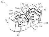
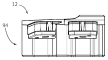
도 1을 참조하면, 봉재-박피 툴 조립체(10)가 도시되어 있다. 조립체(10)는 인서트-홀더(12), 및 인서트-홀더(12) 내의 각각의 위치 및 배향에서 황삭 인서트(14) 및 마감 인서트(16)로서 기능하는 2개의 동일한 인서트(14, 16), 황삭 인서트(14)와 마감 인서트(16) 사이에 각각 위치된 동일한 제1 및 제2 심(18, 20), 그리고 이들이 장착되는 각각의 제1 및 제2 인서트 포켓(22, 24)을 포함한다.Referring to FIG. 1 , a bar-peeling
황삭 인서트(14)는 나사(26)에 의해서 제1 인서트 포켓(22)에 고정된다. 마감 인서트(16)는 유사하게 다른 나사(28)에 의해서 제2 인서트 포켓(22)에 고정된다.The
도 2a, 도 2b, 도 3a 및 도 4a를 또한 참조하여, 2개의 동일한 심들 중 제1 심(18) 만을 설명할 것이다.With reference also to FIGS. 2A, 2B, 3A and 4A , only the
제1 심(18)은 초경합금으로 제조되고, 평면형 (또는, 달리 설명하면, 판) 형상을 갖는다. 더 정확하게, 제1 심(18)은 대향되는 제1 및 제2 심 측면(30, 32) 그리고 심 주변 에지(34)를 포함한다.The
제1 심(18)에는 중앙에 위치된 나사 홀(36) 및 중앙에 위치된 나사 홀로부터 이격된 2개의 심-나사-홀(38, 40)이 형성된다.The
(황삭 인서트(14)(또는 심지어 마감 인서트(16)) 상의 더 큰 힘으로 인해서) 중앙에 위치된 나사 홀(36)은 더 큰 나사(26)를 위한 것이기 때문에, 2개의 심-나사-홀(38, 40)의 각각보다 큰 직경을 갖는다.Since the centrally located threaded
조립 시에, 2개의 별도의 나사(미도시)를 이용하여, 제1 심을 제1 인서트 포켓(22)에 형성된 나사산형의 제1 및 제2 심-나사-홀(38, 40)에 고정한다. 그러나, 황삭 인서트(14)의 안정적인 장착을 방해하지 않게 제1 심 측면과 동일한 높이가 되도록 또는 그 아래에서 유지되도록, 표준 나사가 선택된다(구성된다).When assembling, the first shim is fixed to the threaded first and second shim-screw-
제1 심(18)이 고정되면, 그 후에 황삭 인서트(14)가 나사(26)로 제1 인서트 포켓(22)에 고정될 수 있다.Once the
이제 도 3a 내지 도 3d를 참조하여, 황삭 인서트(14)를 구체적으로 설명할 것이다(심과 유사하게, 2개의 동일한 인서트 중 하나의 인서트, 즉 황삭 인서트(14)만을 설명할 것이다).With reference now to FIGS. 3A-3D , the
황삭 인서트(14)는 제1 레이크 표면(42), 제2 표면(44)(이러한 예에서 또한, 제2 표면(44)이 도 3b의 제1 레이크 표면(42)의 뷰와 동일하기 때문에, 도시되지 않은 평면도에서 "제2 레이크 표면"(44)이다), 제1 레이크 표면(42)과 제2 표면(44)을 연결하는 인서트 주변 표면(46)을 포함한다. 제1 레이크 표면(42) 및 제2 표면(44) 모두가 동일하기 때문에, 제1 레이크 표면(42)만을 구체적으로 설명할 것이다.The
상이한 도면들로부터, 인서트 주변 표면(46)이 제1 레이크 표면(42) 및 제2 표면(44) 모두에 대해서 수직으로 연장되고, 그에 따라 황삭 인서트(14)가 소위 음의 컷팅 인서트라는 것이 이해될 것이다.From the different figures, it is understood that the insert
황삭 인서트(14)는 4개의 동일한 측면을 포함하고, 이들 중 하나만을 구체적으로 설명할 것이다.The
구체적으로, 인서트 주변 표면(46)은 제1, 제2, 제3 및 제4 주변 하위-표면(48, 50, 52, 54), 그리고 제1, 제2, 제3 및 제4 주변 하위-표면들(48, 50, 52, 54)을 연결하는 제1, 제2, 제3 및 제4 모서리(56, 58, 60, 62)를 포함하는 것으로 간주될 수 있다.Specifically, the insert
황삭 인서트(14)는 제1 레이크 표면(42) 및 제2 표면(44)의 중심들을 통해서 연장되는 나사-홀(64)을 포함한다. 전술한 바와 같이, 다른 클램핑 방법이 요구되는 경우에, 그러한 봉재-박피 인서트는 대안적으로 중실형(즉, 나사-홀이 없는) 인서트일 수 있다.The
제1 컷팅 에지(66)가 인서트 주변 표면(46)과 제1 레이크 표면(42)의 교차부를 따라서 연장된다. 이러한 바람직한 예에서, 제1 컷팅 에지(66)는 전체 인서트 주변 표면(46)을 따라서 연장된다.A
보다 정확하게, 제1 컷팅 에지(66)는 제1 주변 하위-표면(48)에 인접한 제1 하위-컷팅 에지(68), 제2 주변 하위-표면(50)에 인접한 제2 하위-컷팅 에지(70), 제3 주변 하위-표면(52)에 인접한 제3 하위-컷팅 에지(72), 및 제4 주변 하위-표면(54)에 인접한 제4 하위-컷팅 에지(74)를 포함한다.More precisely, the
황삭 인서트(14)가 4-방향(90°)으로 인덱스될 수 있기 때문에, 제1 하위-컷팅 에지(68)만을 구체적으로 설명할 것이다.Since the
제1 레이크 표면(42)의 평면도(즉, 도 3b)에서, 제1 하위-컷팅 에지(68)는 중앙에 위치된 직선형 와이퍼 하위-에지(76), 하나의 측면에서 제1 모서리(56)에(또는 보다 정확하게 제1 모서리(56)와 제1 레이크 표면(42)의 교차부에 형성된 제1 모서리 에지(80)에) 연결되는 제1 박피 하위-에지(78), 및 다른 측면에서 제2 모서리(62)에(또는 보다 정확하게 제2 모서리 에지(84))에 연결되는 제2 박피 하위-에지(82)를 포함한다.In a top view (ie, FIG. 3B ) of the
제1 박피 하위-에지(78)(모든 박피 하위-에지들이 동일하다는 것에 주목하여야 한다)는 상기 와이퍼 하위-에지(76)에 연결된 일차 하위-에지(86) 및 제1 모서리(56)에(또는 보다 정확하게 제1 모서리 에지(80)에) 연결된 이차 하위-에지(88)를 포함한다.A first skinning sub-edge 78 (it should be noted that all skinning sub-edges are identical) is attached to a primary sub-edge 86 and a
바람직하게, 일차 하위-에지(86)는 (도 3에 도시된 평면도에서) (이러한 바람직한 예에서 직선형인) 이차 하위-에지(88)보다 더 곡선화된다.Preferably, the primary sub-edge 86 (in the plan view shown in FIG. 3 ) is more curved than the secondary sub-edge 88 (which is straight in this preferred example).
도 3b에 도시된 바와 같이, 제1 및 제2 박피 하위-에지는, (인서트의 중심을 통해서 더 정확하게 제1 레이크 표면(42)의 대향 측면들에 있는 하위-컷팅 에지들(72, 76)에 속하는 와이퍼 하위-에지의 중심들을 통해서 연장되는) 평면(PM)에 의해서 양분되는 와이퍼 하위-에지(76)의 중심(C)에 대해서 거울 대칭적이다.As shown in FIG. 3B , the first and second skinned sub-edges have
특히, 또한 나사-홀 축으로서의 역할을 하는 인서트 축(AS)이 나사-홀(64)의 중심을 통해서 연장되고 평면(PM) 내에 놓인다.In particular, an insert axis A S , which also serves as a screw-hole axis, extends through the center of the screw-
황삭 인서트(14)는 제1 레이크 표면(42) 상에서 그리고 또한 제2 레이크 표면(44) 상에서 인서트 축(AS)을 중심으로 90° 회전 대칭성을 갖는다. 따라서, 일 측면에서, 황삭 인서트(14)는 나사-홀-축(AS)에 대해서 4-방향 회전 인덱스 가능성을 갖는다.The
제1 컷팅 에지(66)로 다시 돌아가면, 모든 컷팅 에지는, 이러한 바람직한 예에서 전체 컷팅 에지(66)에 인접하게 연장되는 홈(90)과 같은 칩-형성부 배열체에 인접하여 위치되는 것이 바람직하다.Returning to the
도 3b에 도시된 바와 같이, 와이퍼 하위-에지(76)의 각각은 가상 사각형(S)을 형성하고, 즉 4개의 와이퍼 에지 모두가 가상 사각형의 상이한 측면들 상에 놓인다.As shown in FIG. 3B , each of the wiper sub-edges 76 forms an imaginary rectangle S, ie all four wiper edges lie on different sides of the imaginary rectangle.
완성을 위해서, 특히 제1 레이크 표면 상의 와이퍼 하위-에지뿐만 아니라 제2 표면의 동일한 도면(미도시)에서 유사한 가상 사각형(미도시)가 제공될 수 있고, 사실상 제1 레이크 표면 및 제2 표면 상의 와이퍼 하위-에지들 사이의 인서트 주변 표면의 부분이 또한 2개의 가상 사각형들을 연결하는 평면 내에 있을 수 있다. 따라서, 8개(각각의 레이크 표면과 연관된 4개)의 와이퍼 하위-에지가 음의(또는 적어도 중간의) 기하형태를 가지는 것으로 간주된다.For completeness, in particular a similar imaginary rectangle (not shown) in the same view (not shown) of the second surface as well as the wiper sub-edge on the first rake surface can be provided, in fact on the first rake surface and on the second surface. The portion of the insert peripheral surface between the wiper sub-edges may also be in the plane connecting the two imaginary rectangles. Thus, eight (four associated with each rake surface) wiper sub-edges are considered to have negative (or at least intermediate) geometry.
또한, 제1 컷팅 에지(66), 또는 보다 정확하게 그 와이퍼 하위-에지(76)는 직경(D)을 갖는 내접 원(IC)을 형성한다. 이러한 바람직한 예에서 직경(D)은 약 35 mm이다.Furthermore, the
직경(D)은 또한 가상 사각형(S)의 인서트 측면-길이(SL)의 길이와 그 길이가 동일하다.The diameter D is also equal to the length of the insert side-length SL of the imaginary rectangle S.
특히, 와이퍼 길이(WL)는 박피 길이(PL)보다 길다.In particular, the wiper length WL is longer than the peeling length PL.
와이퍼 길이(WL)는 이러한 바람직한 예에서 약 14 mm이다.The wiper length (WL) is about 14 mm in this preferred example.
박피 길이(PL)는 이러한 바람직한 예에서 약 8 mm이다.The peel length PL is about 8 mm in this preferred example.
바람직한 실시형태에서, 인서트 측면 길이(SL)의 길이는 와이퍼 길이(WL) 및 박피 길이(PL)의 2배의 합보다도 여전히 더 길다는 것에 또한 주목하여야 한다.It should also be noted that in a preferred embodiment, the length of the insert side length SL is still longer than the sum of two times the wiper length WL and the skin length PL.
유사하게, 일차 하위-에지(86)와 연관된 일차 길이(P1L)는 바람직하게 이차 하위-에지(88)와 연관된 이차 길이(P2L)보다 길다.Similarly, the primary length P1L associated with the primary sub-edge 86 is preferably longer than the secondary length P2L associated with the secondary sub-edge 88 .
일차 길이(P1L)는 이러한 바람직한 예에서 약 6 mm이다.The primary length P1L is about 6 mm in this preferred example.
이차 길이(P2L)는 이러한 바람직한 예에서 약 2 mm이다.The secondary length P2L is about 2 mm in this preferred example.
이제 도 1을 참조하면, 인서트-홀더(12)는 섕크 부분(92) 및 컷팅 부분(94)을 포함한다.Referring now to FIG. 1 , the insert-
도 4a 내지 도 4c를 참조하여, 컷팅 부분(94)을 더 구체적으로 설명할 것이다.4A to 4C, the cutting
전술한 바와 같이, 바람직한 실시형태에서, 컷팅 부분(94)은 동일 방향으로 개방된 제1 및 제2 인서트 포켓(22, 24)을 포함한다.As noted above, in a preferred embodiment, the cutting
제1 인서트 포켓(22)은 포켓 기부 표면(96), 그리고 포켓 기부 표면(96)으로부터 연장되고 원주방향으로 인접한 제1 및 제2 포켓측 표면(98, 100)을 포함한다. 포켓 기부 표면(96)의 평면도(도 4b)에서, 제1 및 제2 포켓측 표면(98, 100)은 제1 가상 사각형(S1)의 2개의 원주방향으로 인접한 측면들을 형성한다.The
제1 인서트 포켓(22)의 (도 4a에 개략적인 해칭으로 도시된) 모든 포켓 접경 표면이 제1 및 제2 포켓측 표면(98, 100) 상에 형성된다.All pocket abutting surfaces (shown in schematic hatching in FIG. 4A ) of the
구체적으로, 제1 포켓측 표면(98)은, 이러한 바람직한 실시형태에서 인서트-홀더(12)의 전방 단부(104)에 인접하는 제1 포켓 접경 표면(102)을 포함한다. 확인하기는 어렵지만, 제1 포켓측 표면(98)의 인접 영역(106)이 제1 포켓 접경 표면(102)의 후방으로 약간 함몰되어, 황삭 인서트(14)가 의도된 접경 지역, 즉 제1 포켓 접경 표면(102)과 접촉되도록 보장한다.Specifically, the first
또한, 전방 단부(104)로부터 가장 먼 포켓측 표면인 제2 포켓측 표면(100)은, 릴리프 함몰부(112)에 의해서 분리된, 제2 포켓 접경 표면(108) 및 제3 포켓 접경 표면(110)을 포함한다.Also, the second pocket-
제1 인서트 포켓(22)은, 이러한 비제한적인 실시형태에서 황삭 인서트(14)와 접촉하지 않도록 의도된 제3 포켓측 표면(114)을 더 포함한다.The
따라서, 도시된 바람직한 실시형태에서, 황삭 인서트(14)는 단지 포켓 기부 표면(96)(또는 더 정확하게, 심을 포함하는 실시형태에서, 포켓 기부 표면(96)과 다시 접촉되는 제1 심(18)) 그리고 단지 제1, 제2, 및 제3 포켓 접경 표면(102, 108, 110)과 접촉된다.Thus, in the preferred embodiment shown, the
상이한 접경 배열체가 제3 포켓측 표면(114) 상의 접경 표면을 포함하는 것이 생각될 수 있다는 것이 이해될 것이다.It will be appreciated that different abutment arrangements are contemplated to include an abutment surface on the
제2 인서트 포켓(24)은 기본적으로 제1 인서트 포켓(22)과 동일하고, 그에 따라 간략하게만 설명할 것이다.The
제2 인서트 포켓(24)은 포켓 기부 표면(116), 제2 가상 사각형(S2)의 2개의 측면들을 형성하는 원주방향으로 인접한 제1 및 제2 포켓측 표면(118, 120)을 포함한다. 인서트-홀더의 컷팅 부분(94)의 평면도(도 4b)에서, 제2 인서트 포켓(24)의 포켓 기부 표면(116) 및 제1 인서트 포켓(22)의 포켓 기부 표면(96)은 동일한 방향을 향한다. 그러나, 평면도에서, 제1 포켓(22)의 각도 배향은 제2 포켓(24)의 각도 배향과 상이하다. 그에 따라, 2개의 포켓(22, 24)의 가상 사각형(S1, S2)의 각각은 상기 평면도 내에서 서로에 대해서 회전되고, 그러한 회전은 상응 가상 사각형(S1 또는 S2)의 중심에 대해서 이루어진다.The
제2 인서트 포켓(24)의 (도 4a에 개략적인 해칭으로 도시된) 모든 포켓 접경 표면이 제1 및 제2 포켓측 표면(118, 120) 상에 형성된다.All pocket abutting surfaces (shown in schematic hatching in FIG. 4A ) of the
구체적으로, 제1 포켓측 표면(118)은 제1 포켓 접경 표면(122)을 포함한다. 제2 포켓측 표면(120)은, 릴리프 함몰부(128)에 의해서 분리된 제2 포켓 접경 표면(124) 및 제3 포켓 접경 표면(126)을 포함한다.Specifically, the first
제2 인서트 포켓(24)은, 이러한 비제한적인 실시형태에서 마감 인서트(16)와 접촉하지 않도록 의도된 제3 포켓측 표면(129)을 더 포함한다.The
따라서, 도시된 바람직한 실시형태에서, 마감 인서트(16)는 단지 포켓 기부 표면(116)(또는 더 정확하게, 심을 포함하는 실시형태에서, 포켓 기부 표면(116)과 다시 접촉되는 제2 심(20)) 그리고 단지 제1, 제2, 및 제3 포켓 접경 표면(122, 124, 126)과 접촉된다.Thus, in the preferred embodiment shown, the
제1 심(18)에 상응하게, 제1 인서트 포켓(22)의 포켓 기부 표면(96)에는 중앙에 위치된 나사산형 나사-홀(130), 및 중앙에 위치된 나사-홀(130)로부터 이격된 2개의 나사산형 심-나사-홀(132, 134)이 형성된다(상응 구성이 제2 인서트 포켓(24)내에 형성된다).Corresponding to the
제1 인서트 포켓(22)의, 제3 포켓측 표면(114), 또는 더 정확하게 제3 포켓측 표면(114)을 포함하는 제1 포켓 벽(114A)은 접경을 위해서 이용되지 않고 그에 따라 필수적이지 않다. 그럼에도 불구하고, 이는 전술한 바와 같이 보호 기능을 제공할 수 있다.The
완성을 위해서, 제2 벽(98A)은 제1 및 제2 인서트 포켓(22, 24)을 분리하고, 제1 인서트 포켓(22)의 제1 포켓측 표면(98)을, 그리고 대향 측면 상에서, 제2 인서트 포켓(24)의 제3 포켓측 표면(129)을 포함한다.For completeness, a
또한, 제3 벽(118A)이 제2 인서트 포켓(24)의 제1 포켓측 표면(118)을 포함한다.The
제1 및 제2 인서트 포켓(22, 24)의 회전된 위치와 관련하여, 제2 인서트 포켓(24)의 제2 및 제3 접경 표면(124, 126)(그리고 이들이 위에 형성되는 제2 포켓측 표면(120)이 기본적으로 인서트-홀더(12)의 (길이방향 축(AE)에 의해서 규정되는) 길이방향에 수직이라는 것에 주목하여야 한다.With respect to the rotated position of the first and second insert pockets 22 , 24 , the second and third abutting
교번적인 방식으로 포켓의 각도 회전을 규정하기 위해서, 인서트-홀더(12)의 컷팅 부분(94)의 평면도(도 4b)에서, 제1 인서트 포켓(22)은, 인서트의 제2 포켓측 표면(100)에 수직이고(그리고 더 정확하게, 그 제2 포켓 접경 표면(108) 및 제3 포켓 접경 표면(110)에 수직이고) 제1 가상 사각형(S1)을 양분하는, 제1 법선(N1)을 갖는다. 한편, 제2 인서트 포켓(24)은, 인서트의 제2 포켓측 표면(120)에 수직이고(그리고 더 정확하게, 그 제2 포켓 접경 표면(124) 및 제3 포켓 접경 표면(126)에 수직이고) 제2 가상 사각형(S2)을 양분하는, 제2 법선(N2)을 갖는다. 제1 법선(N1) 및 제2 법선(N2)은 예각(α)을 형성한다. 일부 실시형태에서, 각도(α)는 30° 내지 50°(즉 30° ≤ α ≤ 50°)이고, 바람직하게: 35° ≤ α ≤ 45°이다. 제2 법선(N2)은 인서트 홀더(12)의 길이방향 축(AE)에 평행할 수 있다.In order to define the angular rotation of the pocket in an alternating manner, in a plan view ( FIG. 4b ) of the cutting
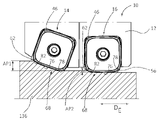
도 5b를 참조하여, 길이방향(DE)을 가지는 봉재(136)에서의 봉재-박피 툴 조립체(10)의 작업을 설명할 것이다. 이러한 도면에서, 하나의 컷팅 인서트가 각각의 인서트 포켓 내에 안착되고, 그러한 인서트의 작업 하위-컷팅 에지(이러한 예에서, 하위-컷팅 에지(68))가 봉재(136)와 결합된다.With reference to FIG. 5B , the operation of the bar-peeling
앞서 주목한 바와 같이, 황삭 인서트(14) 및 마감 인서트(16)는 음의 인서트이고, 그에 따라 인서트-홀더(12)가, 주변 인서트 표면(46)이 약간 보일 수 있다는 점에서 보일 수 있는, 음의 배향을 갖는 릴리프를 제공하는 것이 바람직하다.As noted earlier, the
황삭 인서트(14)는 황삭 기능을 제공하도록, 그에 따라 전체 제1 작업 하위-컷팅 에지(68)(즉, 와이퍼 하위-에지(76) 그리고 제1 및 제2 박피 하위-에지(78, 82) 모두)가 봉재(136)와 결합되어 컷팅 깊이(AP1)에서 재료를 그로부터 제거하도록 배향된다.The
컷팅 깊이(AP1)가 매우 깊고, 황삭 인서트(14) 상의 힘이 특정 적용예에서 너무 큰 경우에 제2 박피 하위-에지(82)가 공작물과 덜 결합하는 상태에서, 확실하게 감소될 수 있다는 것을 이해하여야 한다.If the cutting depth A P1 is very deep and the force on the
그러나, 제2 모서리(62)는, 그 날카로운 그리고 그에 따라 비교적 파괴가 쉬운 구성으로 인해서, 결합되지 않는다.However, the
그럼에도 불구하고, 황삭 인서트(14)의 후속 인덱싱으로, 그 전체 컷팅 에지가 사용될 수 있다는 것이 이해될 것이다.Nevertheless, it will be appreciated that with subsequent indexing of the
유사하게, 마감 인서트(16)는 적은 재료(컷팅 깊이(AP1)와 비교할 때 상대적으로 훨씬 더 얕은 컷팅 깊이(AP2)에 주목하여야 한다)를 제거하도록 그리고 단지 하나의 박피 하위-에지(제2 박피 하위-에지(82)) 및 와이퍼 하위-에지(76)만이 봉재(136)와 결합하는 마감 기능을 제공하도록, 배향된다.Similarly, the finishing
다시, 제2 모서리(62)는 결합되지 않고, 확실하게 제1 모서리(56)는 결합되지 않는다.Again, the
특히, 마감 인서트(16)의 와이퍼 하위-에지(76)는 기본적으로 봉재의 길이방향(DE)과 평행하고, 그에 따라 전술한 바와 같이 와이퍼 기능뿐만 아니라 안정화 기능을 제공한다.In particular, the
전술한 설명은 예시적인 실시형태를 포함하고, 예시되지 않은 실시형태 및 상세 내용을 본원의 청구범위로부터 배제하지 않는다.The foregoing description includes exemplary embodiments and does not exclude non-illustrated embodiments and details from the claims herein.
Claims (23)
제1 레이크 표면 및 그에 대향되게 위치된 제2 표면;
상기 제1 레이크 표면 및 상기 제2 표면 모두의 중심을 통해서 연장되는 인서트 축(As);
상기 제1 레이크 표면과 상기 제2 표면을 연결하는 인서트 주변 표면으로서, 제1, 제2, 제3 및 제4 주변 하위-표면 및 인접한 주변 하위-표면들을 연결하는 제1, 제2, 제3 및 제4 모서리를 포함하는, 인서트 주변 표면; 및
상기 인서트 주변 표면과 상기 제1 레이크 표면의 교차부를 따라서 연장되는 제1 컷팅 에지로서, 인접한 모서리들의 각각의 쌍 사이에서 하위-컷팅 에지를 포함하는, 제1 컷팅 에지를 포함하고;
상기 제1 레이크 표면의 평면도에서, 각각의 하위-컷팅 에지는:
중앙에 위치된 직선형 와이퍼 하위-에지; 및
와이퍼 하위-에지의 대향 측면들 상에 위치되는 제1 및 제2 박피 하위-에지를 포함하고;
제1 박피 하위-에지는 적어도 부분적으로 곡선화되고 와이퍼 하위-에지를 상기 인접 모서리들의 쌍의 하나의 제1 모서리의 제1 모서리 에지에 연결하고;
제2 박피 하위-에지는 상기 와이퍼 하위-에지를 상기 제1 모서리와 동일한 인접 모서리들의 쌍의 제2 모서리의 제2 모서리 에지에 연결하는 적어도 부분적으로 곡선화된 제2 박피 하위-에지이며;
상기 제1 레이크 표면의 평면도에서:
중앙에 위치된 직선형 와이퍼 하위-에지는 인서트를 한정하는 가상 사각형을 형성하고;
제1, 제2, 제3 및 제4 모서리는 상기 가상 사각형으로부터 내측으로 이격되고;
상기 가상 사각형의 측면들은 인서트 측면 길이(SL)를 갖고;
상기 와이퍼 하위-에지는 와이퍼 길이(WL)를 갖는, 사각형-형상의 봉재-박피 인서트.A square-shaped bar-skin insert that:
a first rake surface and a second surface positioned opposite thereto;
an insert axis (As) extending through the center of both the first rake surface and the second surface;
an insert peripheral surface connecting the first rake surface and the second surface, the insert peripheral surface connecting first, second, third and fourth peripheral sub-surfaces and adjacent peripheral sub-surfaces and a fourth edge; and
a first cutting edge extending along the intersection of the insert peripheral surface and the first rake surface, the first cutting edge including a sub-cutting edge between each pair of adjacent edges;
In a plan view of the first rake surface, each sub-cutting edge is:
centrally located straight wiper sub-edge; and
first and second skinned sub-edges positioned on opposite sides of the wiper sub-edge;
a first peel sub-edge is at least partially curved and connects a wiper sub-edge to a first edge edge of a first edge of a first edge of the pair of adjacent edges;
the second peel sub-edge is an at least partially curved second peel sub-edge connecting the wiper sub-edge to a second edge edge of a second edge of a pair of adjacent edges that is the same as the first edge;
In a plan view of the first rake surface:
The centrally located straight wiper sub-edge forms an imaginary rectangle defining the insert;
the first, second, third and fourth edges are spaced inwardly from the imaginary rectangle;
the sides of the imaginary rectangle have an insert side length SL;
wherein the wiper sub-edge has a wiper length (WL).
상기 인서트가 양면형이고, 상기 인서트 주변 표면 및 상기 제2 표면의 교차부를 따라서 연장되는 제2 컷팅 에지를 더 포함하는, 사각형-형상의 봉재-박피 인서트.According to claim 1,
wherein the insert is double-sided and further comprising a second cutting edge extending along the intersection of the insert peripheral surface and the second surface.
상기 제2 컷팅 에지는 인접한 모서리들의 각각의 쌍 사이에서 하위-컷팅 에지를 포함하고; 상기 제2 표면의 평면도에서, 각각의 하위-컷팅 에지는: 중앙에 위치된 직선형 와이퍼 하위-에지; 및 상기 와이퍼 하위-에지의 대향 측면들 상에 위치되는 제1 및 제2 박피 하위-에지를 포함하고; 상기 제1 박피 하위-에지는 적어도 부분적으로 곡선화되고 상기 와이퍼 하위-에지를 상기 인접한 모서리들의 쌍의 하나의 제1 모서리의 제1 모서리 에지에 연결하고; 상기 제2 박피 하위-에지는 상기 와이퍼 하위-에지를 상기 제1 모서리와 동일한 인접한 모서리들의 쌍의 제2 모서리의 제2 모서리 에지에 연결하는 적어도 부분적으로 곡선화된 제2 박피 하위-에지인, 사각형-형상의 봉재-박피 인서트.3. The method of claim 2,
the second cutting edge includes a sub-cutting edge between each pair of adjacent edges; In a plan view of the second surface, each sub-cutting edge comprises: a centrally located straight wiper sub-edge; and first and second skinned sub-edges positioned on opposite sides of the wiper sub-edge; the first peeling sub-edge is at least partially curved and connecting the wiper sub-edge to a first corner edge of one first edge of the pair of adjacent edges; wherein the second skinning sub-edge is an at least partially curved second skinning sub-edge connecting the wiper sub-edge to a second corner edge of a second edge of the same pair of adjacent edges as the first edge. Square-shaped bar-skin inserts.
상기 인서트 주변 표면이 상기 제1 레이크 표면 및 제2 표면 모두에 대해서 수직으로 연장되는, 사각형-형상의 봉재-박피 인서트.4. The method according to any one of claims 1 to 3,
and wherein the insert peripheral surface extends perpendicular to both the first rake surface and the second surface.
제1 및 제2 박피 하위-에지의 각각은 상기 와이퍼 하위-에지에 연결된 일차 하위-에지 및 하나의 측면에서 일차 하위-에지에 그리고 다른 측면에서 상기 모서리에 연결된 이차 하위-에지를 포함하고; 상기 평면도에서, 일차 하위-에지는 이차 하위-에지보다 더 곡선화되는, 사각형-형상의 봉재-박피 인서트.5. The method according to any one of claims 1 to 4,
each of the first and second skinning sub-edges comprises a primary sub-edge connected to the wiper sub-edge and a secondary sub-edge connected on one side to the primary sub-edge and on the other side to the edge; In the top view, the primary sub-edge is more curved than the secondary sub-edge.
상기 평면도에서, 상기 이차 하위-에지가 직선형인, 사각형-형상의 봉재-박피 인서트.6. The method of claim 5,
In the top view, the secondary sub-edge is straight, a square-shaped bar-skin insert.
상기 인서트가 이하의 조건: WL/SL < 0.6을 만족시키는, 사각형-형상의 봉재-박피 인서트.7. The method according to any one of claims 1 to 6,
A square-shaped bar-skinned insert, wherein the insert satisfies the following condition: WL/SL < 0.6.
상기 인서트가 이하의 조건: WL/SL > 0.20을 만족시키는, 사각형-형상의 봉재-박피 인서트.8. The method of claim 7,
The insert satisfies the following condition: WL/SL > 0.20, a square-shaped bar-skinned insert.
각각의 모서리가 상기 제1 및 제2 박피 하위-에지 중 임의의 것보다 작은 모서리 반경을 가지는, 사각형-형상의 봉재-박피 인서트.9. The method according to any one of claims 1 to 8,
wherein each corner has a corner radius less than any of the first and second skinned sub-edges.
각각의 모서리가 상기 일차 하위-에지 중 임의의 것보다 작은 모서리 반경을 가지는, 사각형-형상의 봉재-박피 인서트.10. The method according to any one of claims 5 to 9,
A square-shaped bar-skin insert, wherein each corner has a corner radius less than any of the primary sub-edges.
상기 가상 사각형의 측면들 중 연관된 하나에 평행한 방향을 따른 각각의 박피 하위-에지의 길이가 박피 길이(PL)를 규정하고; 상기 인서트는 이하의 조건: PL/SL < 0.3을 만족시키는, 사각형-형상의 봉재-박피 인서트.11. The method according to any one of claims 1 to 10,
the length of each dermabrasion sub-edge along a direction parallel to an associated one of the sides of the imaginary rectangle defines a dermabrasion length (PL); The insert satisfies the following conditions: PL/SL < 0.3, a square-shaped bar-skinned insert.
상기 인서트가 이하의 조건: PL/SL > 0.15을 만족시키는, 사각형-형상의 봉재-박피 인서트.12. The method of claim 11,
A square-shaped bar-skinned insert, wherein the insert satisfies the following condition: PL/SL > 0.15.
상기 제1 컷팅 에지가 상기 인서트 축(As)을 중심으로 90° 회전 대칭적인, 사각형-형상의 봉재-박피 인서트.13. The method according to any one of claims 1 to 12,
and wherein the first cutting edge is 90° rotationally symmetric about the insert axis (As).
각각의 인서트 포켓의 제1 및 제2 포켓측 표면들이 서로 원주방향으로 인접하고 가상 사각형의 인접 측면들을 따라서 연장되는, 봉재-박피 인서트-홀더.15. The method of claim 14,
A bar-skin insert-holder, wherein the first and second pocket-side surfaces of each insert pocket are circumferentially adjacent to each other and extend along adjacent sides of the imaginary rectangle.
상기 제1 인서트 포켓은 포켓 기부 표면으로부터 연장되는 제3 포켓측 표면을 포함하고, 상기 제1 인서트 포켓의 포켓 기부 표면의 평면도에서, 상기 제3 포켓측 표면이 제1 인서트 포켓의 상기 가상 사각형의 측면을 형성하고; 상기 제2 인서트 포켓은 상기 포켓 기부 표면으로부터 연장되는 제3 포켓측 표면을 포함하고; 상기 제2 인서트 포켓의 포켓 기부 표면의 평면도에서, 상기 제3 포켓측 표면이 제2 인서트 포켓의 상기 가상 사각형의 측면을 형성하는, 봉재-박피 인서트-홀더.16. The method of claim 14 or 15,
The first insert pocket includes a third pocket-side surface extending from a pocket base surface, and in a plan view of the pocket base surface of the first insert pocket, the third pocket-side surface is the imaginary rectangle of the first insert pocket. forming a side; the second insert pocket includes a third pocket side surface extending from the pocket base surface; in a plan view of the pocket base surface of the second insert pocket, wherein the third pocket side surface forms the side of the imaginary rectangle of the second insert pocket.
상기 포켓 기부 표면의 적어도 하나에, 중앙에 위치된 나사 홀 및 상기 중앙에 위치된 나사 홀로부터 이격된 2개의 심-나사-홀이 형성되는, 봉재-박피 인서트-홀더.17. The method according to any one of claims 14 to 16,
and a centrally located threaded hole and two shim-threaded-holes spaced apart from the centrally located threaded hole are formed in at least one of the pocket base surface.
상기 제2 인서트 포켓의 제1 및 제2 포켓측 표면 중 하나가 인서트-홀더의 길이방향과 평행한, 봉재-박피 인서트-홀더.18. The method according to any one of claims 14 to 17,
and one of the first and second pocket-side surfaces of the second insert pocket is parallel to the longitudinal direction of the insert-holder.
상기 봉재-박피 툴 조립체가 길이방향(DE)을 가지는 봉재 공작물과 접촉되며: 상기 제1 및 제2 인서트 모두는 봉재 공작물과 접촉되고; 상기 제1 인서트는, 제1 작업 하위-컷팅 에지의 와이퍼 하위-에지 및 적어도 하나의 박피 하위-에지가 상기 봉재 공작물과 접촉되도록, 배향되며; 상기 제2 인서트는, 제2 작업 하위-컷팅 에지의 적어도 와이퍼 하위-에지가 상기 봉재 공작물과 접촉되도록, 배향되며; 상기 제2 작업 하위-컷팅 에지의 와이퍼 하위-에지는 상기 봉재 공작물의 길이방향에 평행한, 봉재-박피 툴 조립체.20. The method of claim 19,
the bar-skin tool assembly is in contact with a bar workpiece having a longitudinal direction (D E ): both the first and second inserts are in contact with the bar workpiece; the first insert is oriented such that a wiper sub-edge of a first working sub-cutting edge and at least one skinning sub-edge are in contact with the bar workpiece; the second insert is oriented such that at least a wiper sub-edge of a second working sub-cutting edge is in contact with the bar workpiece; and a wiper sub-edge of the second working sub-cutting edge is parallel to the longitudinal direction of the bar workpiece.
상기 제1 작업 하위-컷팅 에지의 양쪽 박피 하위-에지가 상기 봉재 공작물과 접촉되는, 봉재-박피 툴 조립체.21. The method of claim 20,
wherein both skinning sub-edges of the first working sub-cutting edge are in contact with the bar workpiece.
상기 제2 작업 하위-컷팅 에지는 봉재 공작물과 접촉되는 하나의 박피 하위-에지를 갖고, 상기 하나의 박피 하위-에지는 제2 작업 하위-컷팅 에지의 다른 박피 하위-에지보다 제1 인서트에 더 근접하는, 봉재-박피 툴 조립체.22. The method of claim 20 or 21,
the second working sub-cutting edge has one skinning sub-edge in contact with the bar workpiece, the one skinning sub-edge being more in the first insert than the other skinning sub-edges of the second working sub-cutting edge Adjacent, bar-peel tool assembly.
제2 작업 하위-컷팅 에지의 상기 다른 박피 하위-에지가 봉재 공작물과 접촉되지 않는, 봉재-박피 툴 조립체.23. The method of claim 22,
and the other skinning sub-edge of a second working sub-cutting edge is not in contact with the bar workpiece.
Applications Claiming Priority (3)
| Application Number | Priority Date | Filing Date | Title |
|---|---|---|---|
| US202062975259P | 2020-02-12 | 2020-02-12 | |
| US62/975,259 | 2020-02-12 | ||
| PCT/IL2021/050084 WO2021161301A1 (en) | 2020-02-12 | 2021-01-26 | Square-shaped insert for bar-peeling and insert-holder tool for same |
Publications (1)
| Publication Number | Publication Date |
|---|---|
| KR20220130718A true KR20220130718A (en) | 2022-09-27 |
Family
ID=74626045
Family Applications (1)
| Application Number | Title | Priority Date | Filing Date |
|---|---|---|---|
| KR1020227027203A KR20220130718A (en) | 2020-02-12 | 2021-01-26 | Rectangular-shaped inserts for bar peeling and insert-holder tools therefor |
Country Status (10)
| Country | Link |
|---|---|
| US (1) | US11833593B2 (en) |
| EP (1) | EP4103345A1 (en) |
| JP (1) | JP2023512150A (en) |
| KR (1) | KR20220130718A (en) |
| CN (1) | CN115038537A (en) |
| BR (1) | BR112022013121A2 (en) |
| CA (1) | CA3163967A1 (en) |
| IL (1) | IL294579A (en) |
| TW (1) | TW202130433A (en) |
| WO (1) | WO2021161301A1 (en) |
Family Cites Families (39)
| Publication number | Priority date | Publication date | Assignee | Title |
|---|---|---|---|---|
| FR2359667A1 (en) | 1976-07-29 | 1978-02-24 | Ugine Aciers | Tungsten carbide cutter for round bar - is multi-sided and angle between faces is obtuse |
| DE2820810A1 (en) | 1978-05-12 | 1979-11-15 | Kieserling & Albrecht | Blade for metal shaving machine tool - has inclined contour formed in two stages to reduce risk of fracture |
| FR2483819A1 (en) | 1980-06-10 | 1981-12-11 | Eurotungstene | Cutting tool for tubes and bars - is shaped as equilateral triangle with curved sides and rounded angles, tangential to bar |
| JPH0135777Y2 (en) * | 1985-05-25 | 1989-11-01 | ||
| SE448431B (en) | 1985-07-03 | 1987-02-23 | Santrade Ltd | REQUEST FOR TEAM DISPOSAL PROCESSING |
| DE3540665A1 (en) | 1985-11-16 | 1987-05-21 | Kieserling & Albrecht | Cutter combination |
| SE459237B (en) | 1987-10-26 | 1989-06-19 | Sandvik Ab | TRIBUTES BEFORE PLANNING |
| US4880338A (en) | 1988-12-07 | 1989-11-14 | Gte Valenite Corporation | Cutting insert |
| SE502261C2 (en) | 1991-03-04 | 1995-09-25 | Sandvik Ab | Scale turning tools provided with polygonal rough cutters and finished cutters |
| EP0506078B1 (en) | 1991-03-29 | 1996-12-11 | Mitsubishi Materials Corporation | Indexable cutter insert |
| US5807031A (en) | 1995-03-10 | 1998-09-15 | Mitsubishi Materials Corp. | Throw-away tip and throw-away type cutter |
| SE511550C2 (en) | 1996-10-17 | 1999-10-18 | Seco Tools Ab | Tools and cutters for milling |
| JP3371733B2 (en) | 1997-02-06 | 2003-01-27 | 住友電気工業株式会社 | Indexable tip |
| SE511224C2 (en) | 1997-04-30 | 1999-08-30 | Seco Tools Ab | drilling Tools |
| SE509306C2 (en) | 1998-04-29 | 1999-01-11 | Sandvik Ab | Cutter for cranking |
| DE29815761U1 (en) | 1998-09-02 | 2000-01-05 | Hartmetall Beteiligungs Gmbh | Indexable insert for pipe peeling |
| KR100387406B1 (en) | 2000-08-29 | 2003-06-18 | 한국야금 주식회사 | Cutting insert with curved cutting edge |
| US6742969B1 (en) | 2002-12-24 | 2004-06-01 | Kennametal Inc. | Milling cutter insert with chip control and milling cutter using the same |
| SE526234C2 (en) | 2003-03-12 | 2005-08-02 | Sandvik Intellectual Property | Rotatable cutting tool as well as cutting with bevelled flat edge |
| US7220083B2 (en) | 2003-10-15 | 2007-05-22 | Tdy Industries, Inc. | Cutting insert for high feed face milling |
| AT501655B1 (en) | 2005-03-24 | 2007-10-15 | Boehlerit Gmbh & Co Kg | CUTTING PLATE FOR SWIVEL CUTTING |
| IL169340A (en) * | 2005-06-22 | 2010-04-29 | Gil Hecht | Cutting insert |
| KR100887787B1 (en) * | 2007-08-29 | 2009-03-09 | 대구텍 주식회사 | Cutting insert |
| KR101082042B1 (en) | 2009-04-02 | 2011-11-10 | 대구텍 유한회사 | Cutting insert for dual purpose of roughing and finishing |
| KR101097658B1 (en) | 2009-05-29 | 2011-12-22 | 대구텍 유한회사 | Cutting insert |
| RU2011151385A (en) * | 2009-06-16 | 2013-07-27 | Тунгалой Корпорейшн | CUTTING PLATE AND FRONT MILL WITH INDEXED CUTTING PLATES |
| KR101606935B1 (en) | 2009-07-09 | 2016-03-28 | 대구텍 유한회사 | Assembly of double-sided indexable cutting insert and reinforced part |
| US20120282048A1 (en) * | 2011-05-03 | 2012-11-08 | Diamond Innovations, Inc. | Insert With A Wiper To Induce Chip Thinning On A Leading Edge |
| US9079251B2 (en) * | 2011-10-25 | 2015-07-14 | Kennametal Inc. | Cutting inserts having discontiguous clearance faces |
| US9475134B2 (en) * | 2011-12-19 | 2016-10-25 | Iscar, Ltd. | Cutting insert and cutting tool |
| KR101431891B1 (en) | 2012-02-08 | 2014-08-26 | 대구텍 유한회사 | A cutting insert having eight main cutting edges and wiper edges and a cutting tool having the same |
| JP5401732B1 (en) * | 2012-10-23 | 2014-01-29 | 住友電工ハードメタル株式会社 | Milling insert changeable cutting insert |
| CN104203470B (en) * | 2012-11-26 | 2017-04-05 | 住友电工硬质合金株式会社 | Milling cutter |
| JP6205726B2 (en) * | 2013-01-15 | 2017-10-04 | 三菱マテリアル株式会社 | Cutting inserts for face milling and exchangeable face milling |
| EP2946858B1 (en) | 2014-05-19 | 2019-07-10 | Sandvik Intellectual Property AB | Cutting tool insert and cutting tool insert holder |
| AT14282U1 (en) * | 2014-09-03 | 2015-07-15 | Ceratizit Austria Gmbh | Double-sided cutting insert and milling tool |
| DE112016001367B4 (en) * | 2015-03-23 | 2023-08-17 | Kyocera Corporation | Insert, drill and method of making a machined product using the same |
| US20170120351A1 (en) * | 2015-11-03 | 2017-05-04 | Kennametal Inc. | Double-sided cutting inserts with positive clearance face geometry |
| AT15155U1 (en) | 2016-02-26 | 2017-01-15 | Ceratizit Austria Gmbh | peeling plate |
-
2020
- 2020-11-27 TW TW109141700A patent/TW202130433A/en unknown
- 2020-12-01 US US17/108,248 patent/US11833593B2/en active Active
-
2021
- 2021-01-26 BR BR112022013121A patent/BR112022013121A2/en unknown
- 2021-01-26 JP JP2022539732A patent/JP2023512150A/en active Pending
- 2021-01-26 CA CA3163967A patent/CA3163967A1/en active Pending
- 2021-01-26 KR KR1020227027203A patent/KR20220130718A/en unknown
- 2021-01-26 EP EP21705626.6A patent/EP4103345A1/en active Pending
- 2021-01-26 WO PCT/IL2021/050084 patent/WO2021161301A1/en unknown
- 2021-01-26 CN CN202180014384.0A patent/CN115038537A/en active Pending
- 2021-01-26 IL IL294579A patent/IL294579A/en unknown
Also Published As
| Publication number | Publication date |
|---|---|
| CA3163967A1 (en) | 2021-08-19 |
| WO2021161301A1 (en) | 2021-08-19 |
| JP2023512150A (en) | 2023-03-24 |
| US20210245258A1 (en) | 2021-08-12 |
| CN115038537A (en) | 2022-09-09 |
| US11833593B2 (en) | 2023-12-05 |
| BR112022013121A2 (en) | 2022-09-06 |
| TW202130433A (en) | 2021-08-16 |
| IL294579A (en) | 2022-09-01 |
| EP4103345A1 (en) | 2022-12-21 |
Similar Documents
| Publication | Publication Date | Title |
|---|---|---|
| US9623493B2 (en) | Double-sided ball end mill cutting insert and tool therefor | |
| KR101292441B1 (en) | Tangential cutting insert | |
| KR100887787B1 (en) | Cutting insert | |
| US8523498B2 (en) | Cutting insert and face milling cutter | |
| JP5363469B2 (en) | Tool for machining chip removal type and its body and indexable cutting insert | |
| KR101181681B1 (en) | Indexable cutting bit for turning | |
| US20060056928A1 (en) | Indexable insert with corners with different radii | |
| JP6048715B1 (en) | Cutting inserts, tool bodies and cutting tools | |
| JP5779830B2 (en) | Vertical cutting edge replaceable cutting insert and corner milling cutter | |
| US9802255B2 (en) | Rhombus-shaped reversible cutting insert and support seat therefor | |
| JP2015523228A (en) | Cutting insert and cutting tool including the same | |
| JPWO2008123424A1 (en) | Sheet member, rotary tool using the same, and cutting method using the same | |
| JP2007098506A (en) | Throw-away tip and throw-away end mill | |
| KR20220130718A (en) | Rectangular-shaped inserts for bar peeling and insert-holder tools therefor | |
| JP5430069B2 (en) | Milling tool and cutting method using the same | |
| JP4952068B2 (en) | Throw-away rotary tool | |
| JP2016187836A (en) | Cutting insert and cutting edge replaceable cutting tool | |
| JP2017221982A (en) | Tip exchange type cutting tool holder and tip exchange type cutting tool | |
| JP2008290214A (en) | Tip for boring and boring tool using the same | |
| KR20230100150A (en) | Cutting insert and Cutting tool | |
| KR100997815B1 (en) | Cutting insert | |
| JP2009184086A (en) | Throw-away tip | |
| WO2015012232A1 (en) | Cutting insert and cutting tool | |
| JP2015093342A (en) | Cutting insert and cutting edge replaceable hole drilling tool |