JP2017221982A - Tip exchange type cutting tool holder and tip exchange type cutting tool - Google Patents
Tip exchange type cutting tool holder and tip exchange type cutting tool Download PDFInfo
- Publication number
- JP2017221982A JP2017221982A JP2016117078A JP2016117078A JP2017221982A JP 2017221982 A JP2017221982 A JP 2017221982A JP 2016117078 A JP2016117078 A JP 2016117078A JP 2016117078 A JP2016117078 A JP 2016117078A JP 2017221982 A JP2017221982 A JP 2017221982A
- Authority
- JP
- Japan
- Prior art keywords
- insert
- mounting seat
- polygonal
- cutting
- clamp screw
- Prior art date
- Legal status (The legal status is an assumption and is not a legal conclusion. Google has not performed a legal analysis and makes no representation as to the accuracy of the status listed.)
- Pending
Links
Images


Abstract
Description
本発明は、多角形板状の切削インサートがその2つの多角形面のうちの1つを逃げ面としてホルダ本体の外側に向けて着脱可能に取り付けられる縦刃型の刃先交換式切削工具用ホルダ、およびこの刃先交換式切削工具用ホルダに切削インサートを着脱可能に取り付けた縦刃型の刃先交換式切削工具に関するものである。 The present invention relates to a vertical blade type cutting edge-replaceable cutting tool holder in which a polygonal plate-shaped cutting insert is detachably mounted toward one side of the holder body with one of the two polygonal surfaces as a flank. Further, the present invention relates to a blade type replaceable cutting tool of a vertical blade type in which a cutting insert is detachably attached to the blade replaceable cutting tool holder.
このような縦刃型の刃先交換式切削工具として、例えば特許文献1には、対向する二つの同一な端面と、これら端面の間に延在し、対向する二つの同一な主側面を有する周辺側面と、各主側面と各端面との交差部に形成され、間隔を置いて設けられた四つの主切削刃と、各主切削刃に隣接した一次逃げ面とを具えた切削インサートが、この切削インサートを保持する少なくとも一つのインサートポケットを有するカッタ本体(ホルダ本体)に取り付けられた刃先交換式のミリングカッタ(エンドミル)が記載されている。
As such a vertical blade type cutting edge exchangeable cutting tool, for example, in
この特許文献1に記載された刃先交換式切削工具用ホルダでは、上記少なくとも一つのインサートポケット(インサート取付座)がベース(取付座底面)をほぼ横断する隣接する側壁と後壁を具え、ベースは切削インサートをインサートポケットに固定するための締め付けねじを受け入れるねじ山付きの孔(クランプネジ孔)を具え、側壁は少なくとも一つの切削インサートの所与の副側面に当接する軸方向位置決め面を具え、後壁はそれの中心の凹み領域の両側に位置決めされる二つの突出した接線方向の位置決め面を具え、該面は前記少なくとも一つの切削インサートの所与の内側端面に当接する。
In the holder for cutting edge replacement type cutting tool described in
また、特許文献2には、上述のような切削インサートと、この切削インサートを保持するインサートポケット(インサート取付座)を有するインサートホルダ(ホルダ本体)とを備え、インサートポケットは、切削インサートの所与の主側部面によって当接されるベース面(取付座底面)と、このベース面から直立に延在して切削インサートの所与の副側部面によって当接される第一側部壁と、ベース面と第一側部壁とから直立に延在して横切る第二側部壁とを備え、インサート貫通穴(取付孔)を貫通して伸びる固定ねじ(クランプネジ)をベース面のねじ切った受取穴(クランプネジ孔)に螺合することによりインサートポケットに切削インサートを固定するようにした刃先交換式のバイトが記載されている。
ところで、このような縦刃型の刃先交換式切削工具においては、特に特許文献1に記載された刃先交換式エンドミルのようにホルダ本体先端部に複数のインサート取付座が周方向に間隔をあけて形成されている場合に、このホルダ本体先端部の外径が小さくなると、複数のインサート取付座の取付座底面からホルダ本体の内周側に延びるクランプネジ孔にねじ込まれるクランプネジ同士が干渉してしまうため、クランプネジのネジ部の長さを十分に確保することができなくなってしまう。
By the way, in such a vertical blade type cutting edge exchangeable cutting tool, a plurality of insert mounting seats are spaced apart in the circumferential direction at the tip of the holder body, particularly like the blade edge exchangeable end mill described in
そして、このようにクランプネジのネジ部の長さが十分に確保できなくなると、クランプネジ孔とのネジ同士の接触面積も低減して摩擦力が不足し、クランプネジの緩みや切削インサートの取付剛性の不足を招くおそれがある。これは、特許文献2に記載された刃先交換式のバイトでも、例えば小径孔の中繰り加工を行うような場合に、ホルダ本体先端部の外径を小さくせざるを得ないときでも同様である。
If the length of the screw part of the clamp screw cannot be secured sufficiently in this way, the contact area between the screws with the clamp screw hole is also reduced, resulting in insufficient frictional force, loosening of the clamp screw and attachment of the cutting insert. There is a risk of lack of rigidity. This is the same even when the cutting edge exchange type tool described in
本発明は、このような背景の下になされたもので、インサート取付座が形成されるホルダ本体先端部の外径が小さいような場合でも、クランプネジとクランプネジ孔とのネジ同士の接触面積を確保してクランプネジの緩みを防ぐとともに切削インサートを高い剛性で取り付けることが可能な刃先交換式切削工具用ホルダおよび刃先交換式切削工具を提供することを目的としている。 The present invention is made under such a background, and even when the outer diameter of the tip of the holder body on which the insert mounting seat is formed is small, the contact area between the screws of the clamp screw and the clamp screw hole It is an object of the present invention to provide a blade-tip-exchange-type cutting tool holder and a blade-tip-exchange-type cutting tool that can prevent the clamp screw from loosening and attach the cutting insert with high rigidity.
上記課題を解決して、このような目的を達成するために、本発明の刃先交換式切削工具用ホルダは、ホルダ本体の外面にインサート取付座が形成されており、このインサート取付座には上記ホルダ本体の外側を向く取付座底面が備えられていて、この取付座底面の中央部には上記ホルダ本体の外側に突出する凸部が形成されるとともに、この凸部の突端面から上記ホルダ本体の内側に向けては、インサート取付用のクランプネジ孔が形成されており、上記インサート取付座には、多角形板状のインサート本体を備えて該インサート本体の互いに反対側を向く2つの多角形面の中央部に上記インサート本体を貫通する取付孔が開口した切削インサートが、上記2つの多角形面のうち一方の多角形面を上記取付座底面に密着させるとともに他方の多角形面を逃げ面として上記ホルダ本体の外側に向け、上記一方の多角形面における上記取付孔の開口部に上記凸部を収容して、上記他方の多角形面側から上記取付孔に挿通されたクランプネジが上記クランプネジ孔にねじ込まれることにより着脱可能に取り付けられることを特徴とする。 In order to solve the above problems and achieve such an object, the holder for cutting edge replacement type cutting tool of the present invention has an insert mounting seat formed on the outer surface of the holder body, A mounting seat bottom surface facing the outside of the holder body is provided, and a convex portion that protrudes outward from the holder body is formed at the center of the mounting seat bottom surface, and the holder body from the projecting end surface of the projection portion. A clamp screw hole for mounting an insert is formed on the inside of the insert, and the insert mounting seat has a polygonal plate-like insert body and two polygons facing the opposite sides of the insert body. A cutting insert having a mounting hole that opens through the insert body at the center of the surface causes one of the two polygonal surfaces to be in close contact with the bottom surface of the mounting seat and the other. The convex surface is accommodated in the opening of the mounting hole in the one polygonal surface with the square surface as the flank and facing the outside of the holder body, and is inserted into the mounting hole from the other polygonal surface side. The clamp screw is detachably attached by being screwed into the clamp screw hole.
また、本発明の刃先交換式切削工具は、このような刃先交換式切削工具用ホルダにおける上記インサート取付座に切削インサートがクランプネジによって着脱可能に取り付けられた刃先交換式切削工具であって、上記切削インサートは多角形板状のインサート本体を備え、このインサート本体の互いに反対側を向く2つの多角形面の中央部には上記インサート本体を貫通する取付孔が開口しており、上記切削インサートは、上記2つの多角形面のうち一方の多角形面を上記取付座底面に密着させるとともに他方の多角形面を逃げ面として上記ホルダ本体の外側に向け、上記一方の多角形面における上記取付孔の開口部に上記凸部を収容して、上記他方の多角形面側から上記取付孔に挿通された上記クランプネジが上記クランプネジ孔にねじ込まれることにより着脱可能に取り付けられていることを特徴とする。 Further, the cutting edge replaceable cutting tool of the present invention is a cutting edge replaceable cutting tool in which a cutting insert is detachably attached to the insert mounting seat in such a blade edge replaceable cutting tool holder by a clamp screw. The cutting insert has a polygonal plate-like insert body, and a mounting hole that penetrates the insert body is opened at the center of two polygonal surfaces facing the opposite sides of the insert body. One of the two polygonal surfaces is brought into close contact with the bottom surface of the mounting seat, and the other polygonal surface is used as a flank to face the outside of the holder body, and the mounting hole in the one polygonal surface The clamp screw inserted into the mounting hole from the other polygonal surface side is screwed into the clamp screw hole. And wherein the mounted detachably by being.
このような刃先交換式切削工具用ホルダおよび刃先交換式切削工具においては、インサート取付座の取付座底面にホルダ本体の外側に突出する凸部が形成されて、切削インサートのインサート本体における上記取付孔の開口部に収容されるとともに、クランプネジ孔はこの凸部の突端面からホルダ本体の内側に延びている。このため、ホルダ本体の先端部の外径が小径である場合のように、取付座底面からのクランプネジ孔の孔深さは浅くても、凸部に形成されたクランプネジ孔の分だけねじ込まれるクランプネジのネジ部の長さを長くして、ネジ同士の接触面積を大きく確保することができる。 In such a blade-tip-replaceable cutting tool holder and blade-replaceable cutting tool, a convex portion that protrudes outside the holder body is formed on the bottom surface of the mounting seat of the insert mounting seat, and the mounting hole in the insert body of the cutting insert is formed. The clamp screw hole extends to the inside of the holder main body from the protruding end surface of the convex portion. For this reason, even if the hole depth of the clamp screw hole from the bottom surface of the mounting seat is shallow, as in the case where the outer diameter of the tip of the holder body is small, it is screwed in as much as the clamp screw hole formed in the convex part. By increasing the length of the threaded portion of the clamp screw, a large contact area between the screws can be ensured.
従って、上記構成の刃先交換式切削工具用ホルダおよび刃先交換式切削工具によれば、クランプネジの緩みを防止することができるとともに、高い取付剛性で切削インサートをインサート取付座に取り付けることが可能となる。しかも、ホルダ本体からのクランプネジの突き出し長さは、上記凸部の突端面からの突き出長さとなるので、この突き出し長さを短くすることができ、切削負荷等によるクランプネジの撓みを防止することができる。また、突き出し長さが同じなら、取付座底面の位置をホルダ本体の内側に配置することができるので、ホルダ本体の一層の小径化等にも対応することが可能となる。さらに、切削インサートとホルダ本体とのクリアランスを凸部によって小さくすることができ、インサート本体の傾きなどを抑制することもできる。 Therefore, according to the blade tip replaceable cutting tool holder and the blade replaceable cutting tool configured as described above, the clamp screw can be prevented from loosening and the cutting insert can be attached to the insert mounting seat with high mounting rigidity. Become. Moreover, since the protruding length of the clamp screw from the holder body is the protruding length of the protruding portion from the protruding end surface, the protruding length can be shortened, and bending of the clamp screw due to cutting load or the like can be prevented. be able to. Further, if the protrusion length is the same, the position of the bottom surface of the mounting seat can be arranged inside the holder main body, so that it is possible to cope with a further reduction in the diameter of the holder main body. Furthermore, the clearance between the cutting insert and the holder body can be reduced by the convex portion, and the inclination of the insert body can be suppressed.
ここで、上記刃先交換式切削工具用ホルダが特許文献1に記載されたような刃先交換式のエンドミルである場合には、軸線回りに回転される円柱状の上記ホルダ本体の先端部外周に、少なくとも2つの上記インサート取付座を周方向に間隔をあけて形成し、これらのインサート取付座に上記ホルダ本体の径方向において互いに異なる方向を向いた上記取付座底面を備えて、これらの取付座底面に形成された上記凸部の突端面から上記ホルダ本体の内周側に上記クランプネジ孔を形成することにより、クランプネジ同士が干渉するのを防止することができる。ただし、本発明は、特許文献2に記載された刃先交換式のバイトなどにも適用することが可能である。
Here, in the case where the blade-tip-exchangeable cutting tool holder is a blade-tip-exchangeable end mill as described in
以上説明したように、本発明によれば、ホルダ本体の先端部の外径が小径であるような場合でも、クランプネジとクランプネジ孔のネジ同士の接触面積を確保することができ、クランプネジの緩みや切削インサートの取付剛性不足を防いで、安定した切削加工を行うことが可能となる。 As described above, according to the present invention, even when the outer diameter of the tip of the holder body is small, the contact area between the clamp screw and the screw of the clamp screw hole can be ensured. It is possible to prevent the looseness of the cutting and the mounting rigidity of the cutting insert from being insufficient and perform stable cutting.
図1ないし図5は、本発明の刃先交換式切削工具用ホルダの一実施形態を示すものであり、図6ないし図11は、この実施形態の刃先交換式切削工具用ホルダに切削インサートを取り付けた本発明の刃先交換式切削工具の一実施形態を示すものである。これらの実施形態は、特許文献1に記載されたような刃先交換式エンドミル用のホルダおよび刃先交換式エンドミルに本発明を適用した場合を示すものである。
FIGS. 1 to 5 show an embodiment of a holder for cutting edge replacement type cutting tool according to the present invention. FIGS. 6 to 11 show a cutting insert attached to the holder for cutting edge replacement type cutting tool of this embodiment. 1 shows an embodiment of the cutting edge exchangeable cutting tool of the present invention. These embodiments show a case where the present invention is applied to a holder for a blade-tip replaceable end mill and a blade-tip replaceable end mill as described in
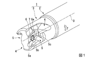
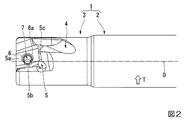
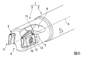
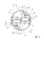
本実施形態において、ホルダ本体1は、鋼材等の金属材料によって軸線Oを中心とした多段円柱状に形成されていて、その後端部(図1ないし図3および図6、図8、図10において右側部分)は円柱状のままのシャンク部2とされるとともに、先端部(図1ないし図3および図6、図8、図10において左側部分)は切削インサートが取り付けられる切刃部3とされている。本実施形態の刃先交換式切削工具は、シャンク部2が工作機械の主軸に把持されて軸線O回りに工具回転方向Tに回転されつつ、通常は軸線Oに垂直な方向に送り出されることにより、切刃部3に取り付けられた切削インサートによって被削材に切削加工を施す。
In the present embodiment, the holder
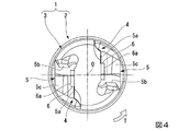
切刃部3は、シャンク部2よりも外径が僅かに小さな外形円柱状に形成され、その外周部には切刃部3の先端面に開口して後端側に延びるチップポケット4が形成されるとともに、このチップポケット4の工具回転方向Tとは反対側には、該チップポケット4に連通するインサート取付座5が、やはり切刃部3の外面である先端面と外周面とに開口する凹所として形成されている。本実施形態では、2つずつのチップポケット4およびインサート取付座5が周方向に等間隔に、軸線Oに関して180°回転対称に形成されている。
The
インサート取付座5は、ホルダ本体1の外周側(外側)を向く取付座底面5aと、この取付座底面5aの工具回転方向Tとは反対側に位置して工具回転方向Tを向く取付座壁面5bと、取付座底面5aの後端側に位置してホルダ本体1の先端側を向く取付座壁面5cとを備えている。従って、2つのインサート取付座5の取付座底面5a同士は、ホルダ本体1の径方向において互いに反対側を向くことになる。また、取付座底面5aと取付座壁面5b、5cとの間および取付座壁面5b、5c同士の間の隅角部と、取付座底面5aおよび取付座壁面5cとチップポケット4との交差稜線部、取付座壁面5b、5cと切刃部3の外周面との交差稜線部には、切削インサートとの干渉を避けるための凹状の逃げ部が形成されている。
The
これら取付座底面5aおよび取付座壁面5b、5cは、次述する取付座底面5aの凸部6を除いて平面状に形成されている。このうち、取付座底面5aが最も面積が大きく、取付座壁面5b、5cの順に面積が小さくなる。本実施形態では、取付座底面5aは図2に示すように略平行四辺形状に形成されており、取付座壁面5b、5cは図1および図3に示すように概略長方形状に形成されている。
The mounting seat
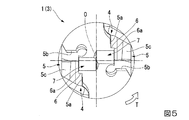
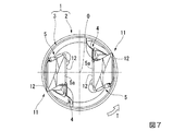
そして、取付座底面5aの中央部には、上述のように略平行四辺形の平面状をなす取付座底面5aから垂直にホルダ本体1の外周側(外側)に突出する凸部6が形成されており、この凸部6の外周側を向く突端面6aからホルダ本体1の内周側(内側)に向けては、インサート取付用のクランプネジ孔7が形成されている。なお、2つのインサート取付座5のクランプネジ孔7同士は、図5に示すように軸線Oから等間隔に工具回転方向T側に偏心しており、ただしその孔底部分は互いに連通している。
And the
また、本実施形態における凸部6は、クランプネジ孔7の中心線を中心とした略円環状またはC字状に取付座底面5aから垂直に突出していて、この中心線に沿った断面は略方形状とされており、ただし一部は取付座底面5aと取付座壁面5bとの間の上記逃げ部によって切り欠かれている。なお、凸部6の断面は、凸部6の外周側が斜辺とされて取付座底面5a側に向かうに従い幅広となる台形状などであってもよい。さらに、凸部6の取付座底面5aからの突出高さは、例えば凸部6の内外径等よりは十分に小さい。
Moreover, the
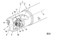
このようなホルダ本体1のインサート取付座5に取り付けられる切削インサートは、ホルダ本体1よりも高硬度の超硬合金等の硬質材料によって形成された多角形板状、詳しくは略平行四辺形板状のインサート本体11を備えており、すなわちこのインサート本体11は、互いに反対側を向く2つの多角形面(平行四辺形面)12と、これらの多角形面12の周りに配置される2つずつの長側面および短側面とを備えている。
The cutting insert attached to the
また、2つの多角形面12の中央部には、インサート本体11を貫通する取付孔13が開口している。そして、この取付孔13に挿通されたクランプネジ14が上記クランプネジ孔7にねじ込まれることにより、インサート本体11はインサート取付座5に着脱可能に取り付けられる。
An
ここで、上記2つの多角形面12がなす平行四辺形は互いに、一方の多角形面12がなす平行四辺形の鋭角角部の反対側に、他方の多角形面12がなす平行四辺形の鈍角角部が位置するようにされている。このようなインサート本体11は、上記取付孔13の中心線に関して180°回転対称形状に形成されるとともに、2つの多角形面12に関して表裏反転対称形状に形成されている。
Here, the parallelogram formed by the two
さらに、各多角形面12と長側面との交差稜線部には、長側面にすくい面を有する主切刃が形成されるとともに、長側面と短側面との交差稜線部の少なくとも上記鋭角角部側には、やはり長側面にすくい面を有する副切刃が形成されている。従って、上記多角形面12は、長側面との交差稜線部に形成された切削に使用される主切刃の逃げ面とされる。なお、多角形面12の中央部と長側面の底面とは略平面状に形成されている。また、各面の面積は、多角形面12が最も大きく、次いで長側面、短側面の順に小さい。
Furthermore, a main cutting edge having a rake face on the long side surface is formed at the cross ridge line portion between each
また、上記取付孔13は、2つの多角形面12における開口部からインサート本体11の内側に向かうに従い縮径するように形成されている。さらに、これらの多角形面12における取付孔13の開口部は、上記クランプネジ14の頭部と、そしてインサート取付座5の取付座底面5aにおける上記凸部6を収容可能な大きさ、すなわち内径と深さとを有している。
Further, the mounting
このような切削インサートは、そのインサート本体11の一方の多角形面12側の取付孔13開口部に上記凸部6を収容しつつ、この一方の多角形面12を取付座底面5aに密着させるとともに他方の多角形面12を逃げ面(外周逃げ面)としてホルダ本体1の外周側に向け、また一方の長側面を工具回転方向Tに向けるとともに他方の長側面を取付座壁面5bに対向させ、さらに一方の短側面をホルダ本体1の先端側に向けるとともに他方の短側面を取付座壁面5cに対向させてインサート取付座5に着座させられる。
In such a cutting insert, the
そして、他方の多角形面12側から上述のように取付孔13に挿通したクランプネジ14をクランプネジ孔7にねじ込むことにより、一方の多角形面12が取付座底面5aに押圧されるとともに、他方の長側面の底面と他方の短側面が取付座壁面5b、5cにそれぞれ当接させられて、切削インサートはインサート取付座5に取り付けられる。このとき、2つのインサート取付座5のクランプネジ孔7にねじ込まれるクランプネジ14のネジ部同士は干渉することのない長さとされ、またクランプネジ14の頭部はインサート本体11の他方の多角形面12側における取付孔13の開口部内に収容される。
Then, by screwing the
このように構成された縦刃型の刃先交換式切削工具(エンドミル)用ホルダおよび刃先交換式切削工具(エンドミル)では、上記他方の多角形面12と一方の長側面および短側面との交差稜線部に形成された主切刃および副切刃が切削に使用される。このとき、多角形板状のインサート本体11のうち最も寸法が小さい厚さの方向(取付孔13の中心線方向)に直交するように延びる最も面積の大きな多角形面12が、主切刃に切削負荷が作用する工具回転方向Tに沿うように配設されるため、特に切削に使用される主切刃の切刃強度を確保して高精度の切削加工を行うことが可能である。
In the thus configured vertical blade type holder for cutting edge-exchangeable cutting tool (end mill) and cutting edge-exchangeable cutting tool (endmill), the intersecting ridge line between the other
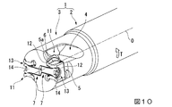
そして、さらに上記構成の刃先交換式切削工具用ホルダおよび刃先交換式切削工具においては、上述のようにインサート取付座5のホルダ本体1外周側を向く取付座底面5aに凸部6が形成されており、切削インサートをインサート取付座5に取り付けた状態では、この凸部6はインサート本体11の取付孔13の開口部に収容されるとともに、インサート本体11を固定するクランプネジ14がねじ込まれるクランプネジ孔7は、この凸部6の突端面6aからホルダ本体1の内周側に延びている。
Further, in the blade-tip-exchangeable cutting tool holder and the blade-tip-exchangeable cutting tool configured as described above, the
このため、ホルダ本体1先端部の切刃部3の外径が小径で、取付座底面5aからクランプネジ孔7の孔底までの孔深さを深くすることができない場合でも、凸部6の内周に形成されたクランプネジ孔7のネジの長さ分(例えばネジ山にして1〜2山分程度)だけ、クランプネジ孔7にねじ込まれるクランプネジ14のネジ部の長さを長くして、クランプネジ孔7とクランプネジ14とのネジ同士の接触面積を大きくすることができる。従って、このようなネジ同士の接触面積が低減して摩擦力が不足することによりクランプネジ14に緩みが生じるのを防ぐことができるとともに、高い取付剛性で切削インサートを取り付けることができ、安定した切削加工を行うことが可能となる。
For this reason, even when the outer diameter of the
また、このような凸部6が形成されて突端面6aからクランプネジ孔7が形成されることにより、クランプネジ14のホルダ本体1からの突き出し長さは、この突端面6aからの突き出し長さとなり、凸部6が形成されずに取付座底面5aにクランプネジ孔7が直接開口している場合に比べ、この突き出し長さを短くすることができる。このため、切削負荷等によってクランプネジ14に撓みが生じるのを防止して、さらに安定した高精度の切削を行うことができる。
Further, by forming such a
一方、逆に取付座底面5aにクランプネジ孔7が直接開口している場合と上記突き出し長さが同じなら、この場合と比べて取付座底面5aの位置を凸部6の突出高さ分だけホルダ本体1の内周側に配置することができる。従って、上記構成の刃先交換式切削工具用ホルダおよび刃先交換式切削工具によれば、クランプネジ孔7とクランプネジ14の接触面積を維持したまま、ホルダ本体1先端部の一層の小径化を図ることが可能となる。さらに、切削インサートの取付孔13の内壁面と凸部6の外周面とのクリアランスを小さくすることで、インサート取付座5におけるインサート本体11の予期せぬ動きなどを抑制することもできる。
On the other hand, if the protruding length is the same as the case where the
また、本実施形態の刃先交換式切削工具用ホルダおよび刃先交換式切削工具は、上述したように軸線O回りに回転される円柱状のホルダ本体1の先端部外周に、2つのインサート取付座5が互いの取付座底面5aを反対側に向けて周方向に間隔をあけて形成され、それぞれに切削インサートがクランプネジ14によって着脱可能に取り付けられた刃先交換式のエンドミル用ホルダおよびエンドミルである。
In addition, the blade-tip-exchangeable cutting tool holder and the blade-tip-exchangeable cutting tool of the present embodiment have two
そして、特に小径の刃先交換式エンドミルにおいて、このように複数のインサート取付座5に切削インサートが取り付けられる場合には、クランプネジ14が干渉し易いのに対し、本発明を適用することによって小径でもクランプネジ孔7との接触面積を確保したまま、クランプネジ14同士の干渉を防ぐことができる。勿論、これは、ホルダ本体1に形成されるインサート取付座5が3つ以上の場合でも同様である。
In particular, in the case of a small-diameter-blade replaceable end mill, when the cutting insert is attached to the plurality of
一方、このようにホルダ本体1に複数のインサート取付座5が形成された刃先交換式エンドミル用ホルダおよび刃先交換式エンドミル以外に、ホルダ本体1の先端部外周に周方向には1つのインサート取付座5しか形成されていない、1枚刃の刃先交換式エンドミル用ホルダおよび刃先交換式エンドミルでも、小径化を図るために取付座底面5aとその反対側の切刃部3外周面との間のホルダ本体1の肉厚が小さくならざるを得ない場合に、本発明は有効である。
On the other hand, in addition to the blade end replaceable end mill holder and the blade end replaceable end mill in which a plurality of
さらにまた、このような刃先交換式のエンドミル用ホルダやエンドミル以外の、特許文献2に記載された刃先交換式バイト用ホルダや刃先交換式バイトにおいても、例えば小径孔の中繰り加工を行うためにホルダ本体1の先端部を小径化する場合には、本発明は有効である。また、例えば軸線回りに回転される薄肉円板状あるいは円環板状のホルダ本体(カッタ本体)の2つの円形の側面や外周面、内周面(外面)にインサート取付座が周方向や軸線方向に交互に形成され、これらのインサート取付座に多角形板状の切削インサートが、その2つの多角形面のうちの1つを逃げ面として軸線方向に向けて取り付けられる縦刃型の刃先交換式サイドカッタや、エクスターナルあるいはインターナルのピンミラーカッタのホルダ本体およびサイドカッタやピンミラーカッタでも、インサート取付座の取付座底面から軸線方向に反対側(内側)のホルダ本体の側面までの肉厚を確保し難い場合に、本発明は有効である。さらに、上記実施形態では、例えば図6に示すように主切刃が軸線Oに略平行に延びるように配設されているが、本発明は、主切刃が軸線Oに対して例えば45°の角度で先端側に向かうに従い内周側に向かうように傾斜した正面フライスのホルダやフライスにも適用可能である。
Furthermore, in addition to such a blade-tip replaceable end mill holder and end mill, the blade-tip replaceable cutting tool holder and the blade-tip replaceable cutting tool described in
1 ホルダ本体
2 シャンク部
3 切刃部
4 チップポケット
5 インサート取付座
5a 取付座底面
5b、5c 取付座壁面
6 凸部
6a 凸部6の突端面
7 クランプネジ孔
11 インサート本体
12 インサート本体11の多角形面
13 取付孔
14 クランプネジ
O ホルダ本体1の軸線
T 工具回転方向
DESCRIPTION OF
Claims (3)
この取付座底面の中央部には上記ホルダ本体の外側に突出する凸部が形成されるとともに、この凸部の突端面から上記ホルダ本体の内側に向けては、インサート取付用のクランプネジ孔が形成されており、
上記インサート取付座には、多角形板状のインサート本体を備えて該インサート本体の互いに反対側を向く2つの多角形面の中央部に上記インサート本体を貫通する取付孔が開口した切削インサートが、上記2つの多角形面のうち一方の多角形面を上記取付座底面に密着させるとともに他方の多角形面を逃げ面として上記ホルダ本体の外側に向け、上記一方の多角形面における上記取付孔の開口部に上記凸部を収容して、上記他方の多角形面側から上記取付孔に挿通されたクランプネジが上記クランプネジ孔にねじ込まれることにより着脱可能に取り付けられることを特徴とする刃先交換式切削工具用ホルダ。 An insert mounting seat is formed on the outer surface of the holder body, and this insert mounting seat is provided with a mounting seat bottom surface facing the outside of the holder body,
A convex portion that protrudes outside the holder body is formed at the center of the bottom surface of the mounting seat, and a clamp screw hole for attaching an insert is formed from the protruding end surface of the convex portion toward the inside of the holder body. Formed,
The insert mounting seat has a polygonal plate-like insert main body, and a cutting insert having a mounting hole opened through the insert main body at the center of two polygonal surfaces facing opposite sides of the insert main body, Of the two polygonal surfaces, one polygonal surface is brought into close contact with the bottom surface of the mounting seat and the other polygonal surface is used as a relief surface toward the outside of the holder body so that the mounting hole in the one polygonal surface is Cutting edge replacement characterized in that the convex portion is accommodated in the opening, and the clamp screw inserted into the attachment hole from the other polygonal surface side is removably attached by being screwed into the clamp screw hole. Type cutting tool holder.
上記切削インサートは多角形板状のインサート本体を備え、このインサート本体の互いに反対側を向く2つの多角形面の中央部には上記インサート本体を貫通する取付孔が開口しており、
上記切削インサートは、上記2つの多角形面のうち一方の多角形面を上記取付座底面に密着させるとともに他方の多角形面を逃げ面として上記ホルダ本体の外側に向け、上記一方の多角形面における上記取付孔の開口部に上記凸部を収容して、上記他方の多角形面側から上記取付孔に挿通された上記クランプネジが上記クランプネジ孔にねじ込まれることにより着脱可能に取り付けられていることを特徴とする刃先交換式切削工具。 A cutting edge replaceable cutting tool in which a cutting insert is detachably attached to the insert mounting seat in the holder for cutting edge replaceable cutting tool according to claim 1 or 2, by a clamp screw,
The cutting insert has a polygonal plate-like insert body, and a mounting hole that penetrates the insert body is opened at the center of two polygonal surfaces facing opposite sides of the insert body.
The cutting insert has one of the two polygonal surfaces in close contact with the bottom surface of the mounting seat and the other polygonal surface serving as a flank toward the outside of the holder body, The convex portion is accommodated in the opening portion of the mounting hole, and the clamp screw inserted into the mounting hole from the other polygonal surface side is detachably mounted by being screwed into the clamp screw hole. A cutting edge exchangeable cutting tool characterized by comprising:
Priority Applications (1)
| Application Number | Priority Date | Filing Date | Title |
|---|---|---|---|
| JP2016117078A JP2017221982A (en) | 2016-06-13 | 2016-06-13 | Tip exchange type cutting tool holder and tip exchange type cutting tool |
Applications Claiming Priority (1)
| Application Number | Priority Date | Filing Date | Title |
|---|---|---|---|
| JP2016117078A JP2017221982A (en) | 2016-06-13 | 2016-06-13 | Tip exchange type cutting tool holder and tip exchange type cutting tool |
Publications (1)
| Publication Number | Publication Date |
|---|---|
| JP2017221982A true JP2017221982A (en) | 2017-12-21 |
Family
ID=60687579
Family Applications (1)
| Application Number | Title | Priority Date | Filing Date |
|---|---|---|---|
| JP2016117078A Pending JP2017221982A (en) | 2016-06-13 | 2016-06-13 | Tip exchange type cutting tool holder and tip exchange type cutting tool |
Country Status (1)
| Country | Link |
|---|---|
| JP (1) | JP2017221982A (en) |
Cited By (1)
| Publication number | Priority date | Publication date | Assignee | Title |
|---|---|---|---|---|
| JP7312364B1 (en) | 2022-10-31 | 2023-07-21 | 株式会社タンガロイ | Cutting tools and their tool bodies |
Citations (7)
| Publication number | Priority date | Publication date | Assignee | Title |
|---|---|---|---|---|
| JP2005518949A (en) * | 2002-03-06 | 2005-06-30 | イスカーリミテッド | Metal cutting tool |
| JP2007520360A (en) * | 2004-02-04 | 2007-07-26 | イスカーリミテッド | Double-sided cutting insert and milling cutter |
| JP2010507496A (en) * | 2006-10-23 | 2010-03-11 | イスカーリミテッド | Replaceable tangential cutting inserts and rotary cutting tools |
| JP2011183490A (en) * | 2010-03-05 | 2011-09-22 | Mitsubishi Materials Corp | Clamp mechanism and edge replacement type tool |
| JP2015112714A (en) * | 2013-12-13 | 2015-06-22 | サンドビック インテレクチュアル プロパティー アクティエボラーグ | Cutting tool with replaceable abutment members and toolholder and cutting insert therefor |
| CN204470681U (en) * | 2014-12-26 | 2015-07-15 | 厦门金鹭特种合金有限公司 | A kind of indexable side and face milling cutter |
| US20150251255A1 (en) * | 2011-12-06 | 2015-09-10 | Korloy Inc | Insert for slot milling |
-
2016
- 2016-06-13 JP JP2016117078A patent/JP2017221982A/en active Pending
Patent Citations (7)
| Publication number | Priority date | Publication date | Assignee | Title |
|---|---|---|---|---|
| JP2005518949A (en) * | 2002-03-06 | 2005-06-30 | イスカーリミテッド | Metal cutting tool |
| JP2007520360A (en) * | 2004-02-04 | 2007-07-26 | イスカーリミテッド | Double-sided cutting insert and milling cutter |
| JP2010507496A (en) * | 2006-10-23 | 2010-03-11 | イスカーリミテッド | Replaceable tangential cutting inserts and rotary cutting tools |
| JP2011183490A (en) * | 2010-03-05 | 2011-09-22 | Mitsubishi Materials Corp | Clamp mechanism and edge replacement type tool |
| US20150251255A1 (en) * | 2011-12-06 | 2015-09-10 | Korloy Inc | Insert for slot milling |
| JP2015112714A (en) * | 2013-12-13 | 2015-06-22 | サンドビック インテレクチュアル プロパティー アクティエボラーグ | Cutting tool with replaceable abutment members and toolholder and cutting insert therefor |
| CN204470681U (en) * | 2014-12-26 | 2015-07-15 | 厦门金鹭特种合金有限公司 | A kind of indexable side and face milling cutter |
Cited By (1)
| Publication number | Priority date | Publication date | Assignee | Title |
|---|---|---|---|---|
| JP7312364B1 (en) | 2022-10-31 | 2023-07-21 | 株式会社タンガロイ | Cutting tools and their tool bodies |
Similar Documents
| Publication | Publication Date | Title |
|---|---|---|
| JP5089616B2 (en) | Cutting inserts and milling tools | |
| CA2752326C (en) | Cutting edge-replaceable cutting tool and cutting insert for use therein | |
| JP5491505B2 (en) | Milling and cutting tips therefor | |
| RU2648717C2 (en) | Rotary cutting tool and reversible cutting insert thereof | |
| US7510353B2 (en) | Indexable cutting tool insert and cutting tool | |
| JP2016172294A (en) | Cutting insert, cutting insert group and indexable cutting tool | |
| US20190084053A1 (en) | Cutting insert and tool for machining | |
| JP2019136802A (en) | Cutting insert and blade edge replaceable-type cutting tool | |
| JP2014083667A (en) | Cutting insert and tip replaceable cutting tool | |
| WO2016093275A1 (en) | Cutting insert, tool body, and cutting tool | |
| JP2017221982A (en) | Tip exchange type cutting tool holder and tip exchange type cutting tool | |
| WO2012131896A1 (en) | Cutting tool with replaceable blade edge | |
| JP4971649B2 (en) | Cutting tools | |
| JP7242997B2 (en) | End mill body of indexable end mill | |
| JP6201735B2 (en) | Replaceable cutting tool | |
| JP2020116707A (en) | Blade edge replaceable end mill | |
| JP2015208835A (en) | Cutting edge replaceable face milling cutter and manufacturing method of the same | |
| JP2019141944A (en) | Cutting insert and screwing structure of cutting insert | |
| US11833593B2 (en) | Square-shaped insert for bar-peeling and insert-holder tool for same | |
| JP7131893B2 (en) | step milling cutter | |
| JP2015229235A (en) | Tip replaceable cutting tool holder | |
| WO2019187150A1 (en) | Face milling cutter | |
| JP6318558B2 (en) | Cutting insert and replaceable edge drilling tool | |
| JP2019177442A (en) | Cutting blade part-position adjustment mechanism and rotary cutting tool | |
| JP2019177440A (en) | Rotary cutting tool |
Legal Events
| Date | Code | Title | Description |
|---|---|---|---|
| RD03 | Notification of appointment of power of attorney |
Free format text: JAPANESE INTERMEDIATE CODE: A7423 Effective date: 20181012 |
|
| A621 | Written request for application examination |
Free format text: JAPANESE INTERMEDIATE CODE: A621 Effective date: 20190315 |
|
| A977 | Report on retrieval |
Free format text: JAPANESE INTERMEDIATE CODE: A971007 Effective date: 20200117 |
|
| A131 | Notification of reasons for refusal |
Free format text: JAPANESE INTERMEDIATE CODE: A131 Effective date: 20200204 |
|
| A02 | Decision of refusal |
Free format text: JAPANESE INTERMEDIATE CODE: A02 Effective date: 20200811 |