JP6201735B2 - Replaceable cutting tool - Google Patents
Replaceable cutting tool Download PDFInfo
- Publication number
- JP6201735B2 JP6201735B2 JP2013265659A JP2013265659A JP6201735B2 JP 6201735 B2 JP6201735 B2 JP 6201735B2 JP 2013265659 A JP2013265659 A JP 2013265659A JP 2013265659 A JP2013265659 A JP 2013265659A JP 6201735 B2 JP6201735 B2 JP 6201735B2
- Authority
- JP
- Japan
- Prior art keywords
- wall surface
- screw hole
- ridge line
- virtual plane
- intersecting ridge
- Prior art date
- Legal status (The legal status is an assumption and is not a legal conclusion. Google has not performed a legal analysis and makes no representation as to the accuracy of the status listed.)
- Active
Links
Images


Description
本発明は、工具本体の外周に形成されたインサート取付座に切削インサートがクランプネジによって着脱可能に取り付けられる刃先交換式のエンドミルのような刃先交換式切削工具に関するものである。 The present invention relates to a blade-tip-exchangeable cutting tool such as a blade-tip-exchangeable end mill in which a cutting insert is removably attached to an insert mounting seat formed on the outer periphery of a tool body by a clamp screw.
このような刃先交換式切削工具として、例えば特許文献1には、略円柱状をなすエンドミル本体の先端部にインサート取付座が形成され、このインサート取付座には、その底面からエンドミル本体の外周面に貫通してネジ穴が形成されて、このネジ穴に、切削インサートを取り付けるクランプネジが螺合せしめられる刃先交換式エンドミルにおいて、エンドミル本体の外周面における上記ネジ穴の開口部周縁部に、該周縁部を略均一な厚さに切除してなる除肉部を形成することにより、ネジ穴の開口部周縁部に切屑が係止されてエンドミル本体にクラックや破断が生じるのを防ぐようにした刃先交換式エンドミルが提案されている。
As such a blade-tip-exchangeable cutting tool, for example, in
また、特許文献2には、このようなネジ穴の開口部周縁部にぬすみ穴を形成する際に、ネジ穴に対してインサート取付座の底面と反対方向の外周面から加工用エンドミルによる穿設加工でぬすみ穴を形成したのでは、ぬすみ穴のネジ穴に連通する部分の外周面との境界部が平面状となって、その両端に角部が形成され、この角部からクラックや欠損が生じるおそれがあるため、ネジ穴に交差する方向にネジ穴と連通する丸型のぬすみ穴を設けることにより、このような角部が形成されないようにしてクラックや欠損を防止した刃先交換式エンドミルが提案されている。
Further, in
ところで、これら特許文献1、2に記載された刃先交換式エンドミルでは、ネジ穴の中心線に沿った方向から見て、上記除肉部やぬすみ穴とエンドミル本体の外周面との交差稜線は楕円形をなすことになり、円形に開口するネジ穴からの距離が長い部分と短い部分とが生じる。このため、特許文献1、2に記載されたような円柱状のエンドミル本体の先端部にその長手方向には1つの切削インサートしか取り付けられていない刃先交換式エンドミルではクラック等を防ぐことができても、例えば長手方向に複数(多数)の切削インサートが取り付けられる刃先交換式エンドミルでは、過大な切削負荷が作用すると、特に後端側(シャンク部側)のインサート取付座において、除肉部やぬすみ穴と工具本体外周面との交差稜線のうち中心線からの距離が短い部分に応力が集中してクラックが発生してしまうおそれがある。
By the way, in the edge-replaceable end mills described in these
本発明は、このような背景の下になされたもので、特にこのような円柱状の工具本体の長手方向に複数の切削インサートが取り付けられる刃先交換式切削工具においても、応力の集中によるクラックの発生を防ぐことが可能な刃先交換式切削工具を提供することを目的としている。 The present invention has been made under such a background. In particular, even in a blade-exchangeable cutting tool in which a plurality of cutting inserts are attached in the longitudinal direction of such a cylindrical tool body, cracks due to stress concentration are generated. An object of the present invention is to provide a cutting edge exchangeable cutting tool capable of preventing the occurrence.
上記課題を解決して、このような目的を達成するために、本発明は、工具本体に形成されたインサート取付座に切削インサートがクランプネジにより着脱可能に取り付けられる刃先交換式切削工具であって、上記工具本体には、上記インサート取付座から延びて上記クランプネジがねじ込まれるクランプネジ穴と、上記インサート取付座に対してこのクランプネジ穴を間にして該工具本体の外面に開口する凹部とが形成され、上記凹部は、上記外面に交差して上記クランプネジ穴が開口する底面と、この底面から上記クランプネジ穴のネジ穴中心線が延びる方向に延びて上記外面に交差する壁面とを備え、上記壁面は、上記外面と上記底面との交差稜線の両端部にそれぞれ連なる2つの壁面部を有し、上記ネジ穴中心線に沿って上記底面に対向する方向から見たときに上記交差稜線と上記ネジ穴中心線とを最短で結ぶ直線と該ネジ穴中心線とを含む仮想平面に対して、上記2つの壁面部のうち少なくとも一方の壁面部は、この一方の壁面部が連なる上記交差稜線の一方の端部に向かうに従い上記仮想平面との間隔が漸次大きくなるように形成され、他方の壁面部は、この他方の壁面部が連なる上記交差稜線の他方の端部に向かうに従い上記仮想平面との間隔が小さくならないように形成されていることを特徴とする。 In order to solve the above-mentioned problems and achieve such an object, the present invention provides a cutting edge exchangeable cutting tool in which a cutting insert is detachably attached to an insert mounting seat formed on a tool body by a clamp screw. The tool body has a clamp screw hole extending from the insert mounting seat and into which the clamp screw is screwed, and a recess opening on the outer surface of the tool body with the clamp screw hole interposed between the insert mounting seat and the tool body. The concave portion includes a bottom surface that intersects the outer surface and opens the clamp screw hole, and a wall surface that extends from the bottom surface in a direction in which the screw hole center line of the clamp screw hole extends and intersects the outer surface. The wall surface has two wall surface portions respectively connected to both end portions of the intersection ridge line between the outer surface and the bottom surface, and is opposed to the bottom surface along the screw hole center line. When viewed from the direction in which the crossing ridge line and the screw hole center line are shortest and a virtual plane including the screw hole center line, at least one wall surface part of the two wall surfaces is The one wall surface portion is formed so that the distance from the virtual plane gradually increases toward one end portion of the intersecting ridge line, and the other wall surface portion is formed by the other wall surface portion. It is characterized in that the distance from the virtual plane does not become smaller toward the other end.
このような刃先交換式切削工具においては、上記凹部の壁面の2つの壁面部のうち少なくとも一方の壁面部が上記交差稜線の一方の端部に向かうに従い上記仮想平面との間隔が漸次大きくなるよう形成にされ、他方の壁面部は上記交差稜線の他方の端部に向かうに従い上記仮想平面との間隔が小さくならないように形成されているので、これに伴いクランプネジ穴が開口する凹部の底面も、一方の壁面部との交差稜線部は上記一方の端部に向かうに従い上記仮想平面との間隔が漸次大きくなり、他方の壁面部との交差稜線部は上記他方の端部に向かうに従い上記仮想平面との間隔が小さくはならない。すなわち、凹部の底面は工具本体の外面との交差稜線側に向かうに従い少なくとも一方の壁面部に向けて幅広となるように形成されるので、過大な負荷が作用しても応力を分散させて最大応力値を低減し、応力の集中によるクラックの発生を防ぐことができる。 In such a blade-tip-exchange-type cutting tool, at least one wall surface portion of the two wall surface portions of the concave portion is gradually increased in distance from the virtual plane as it goes to one end portion of the intersecting ridge line. The other wall surface is formed so that the distance from the imaginary plane does not become smaller toward the other end of the intersecting ridge line. The intersection ridge line portion with one wall surface portion gradually increases in distance to the virtual plane as it goes to the one end portion, and the intersection ridge line portion with the other wall surface portion becomes the virtual portion as it goes to the other end portion. The distance from the plane should not be small. In other words, the bottom surface of the recess is formed so as to become wider toward at least one wall surface as it goes to the side of the ridge line intersecting with the outer surface of the tool body. The stress value can be reduced, and the occurrence of cracks due to stress concentration can be prevented.
また、このように上記交差稜線の一方の端部に向かうに従い上記仮想平面との間隔が漸次大きくなる上記2つの壁面部のうち少なくとも一方の壁面部を、この一方の壁面部が連なる上記交差稜線の一方の端部に向かうに従い、上記ネジ穴中心線に沿って上記底面に対向する方向から見たときに凸曲線をなして上記仮想平面との間隔が大きくなるように形成することにより、この一方の壁面部にも応力が集中するのを防いでクラックの発生を防止することができる。さらに、上記2つの壁面部の双方を、それぞれの壁面部が連なる上記交差稜線の端部に向かうに従い上記仮想平面との間隔が漸次大きくなるように形成することにより、凹部に作用する応力も上記交差稜線の両端部に向けて分散させることができるので、一層確実にクラックの発生を防ぐことができる。 Further, at least one wall surface portion of the two wall surface portions, in which the distance from the virtual plane gradually increases toward the one end portion of the intersecting ridge line, the cross ridge line in which the one wall surface portion continues. By forming a convex curve and increasing the distance from the virtual plane when viewed from the direction facing the bottom surface along the screw hole center line, Generation of cracks can be prevented by preventing stress from concentrating on one wall surface portion. Further, by forming both of the two wall surface portions so that the distance from the virtual plane gradually increases toward the end of the intersecting ridge line where the respective wall surface portions are continuous, the stress acting on the concave portion is also increased. Since it can disperse | distribute toward the both ends of an intersection ridgeline, generation | occurrence | production of a crack can be prevented more reliably.
さらにまた、上記凹部の底面と上記壁面の上記2つの壁面部との交差稜線部を凹曲面状に形成することにより、この交差稜線部に応力が集中してクラックが発生するのも防ぐことができる。従って、刃先交換式のエンドミルのように上記工具本体が円柱状をなしていて、その長手方向に複数の上記インサート取付座が形成されて上記切削インサートが取り付けられていても、特に後端側(シャンク部側)のインサート取付座における損傷を効果的に防止することができる。 Furthermore, by forming the intersecting ridge line portion between the bottom surface of the concave portion and the two wall surface portions of the wall surface in a concave curved surface shape, it is possible to prevent stress from concentrating on the intersecting ridge line portion and generating cracks. it can. Therefore, even if the tool body has a cylindrical shape like a blade-end-exchangeable end mill, and a plurality of the insert mounting seats are formed in the longitudinal direction and the cutting insert is mounted, the rear end side ( Damage to the insert mounting seat on the shank portion side) can be effectively prevented.
以上説明したように、本発明によれば、過大な切削負荷が工具本体に作用しても、クランプネジ穴が開口する凹部の底面に部分的に応力が集中するのを防いで、クラック等の損傷が発生するのを防止することが可能となり、工具寿命の延長を図ることができる。 As described above, according to the present invention, even if an excessive cutting load acts on the tool body, the stress is prevented from being partially concentrated on the bottom surface of the recess where the clamp screw hole is opened, and cracks and the like are prevented. It becomes possible to prevent the occurrence of damage, and the tool life can be extended.
図1ないし図4は、本発明の一実施形態を示すものである。本実施形態の刃先交換式切削工具は、鋼材等の金属材料により形成された軸線Oを中心とする外形略円柱状をなす工具本体1の先端部(図1において左下側部分。図2、4においては左側部分)の外周に、その長手方向(軸線O方向)に向けて複数のインサート取付座2が形成されて切削インサート3が取り付けられた刃先交換式のエンドミルであり、この工具本体1の後端部(図1において右上側部分。図2、4においては右側部分)はシャンク部4とされ、このシャンク部4がマシニングセンタ等の工作機械の主軸に把持されて軸線O回りに工具回転方向Tに回転されつつ、通常は該軸線Oに垂直な方向に送り出されて切削を行う。
1 to 4 show an embodiment of the present invention. The cutting edge-exchangeable cutting tool of this embodiment is a distal end portion of a
より詳しくは、工具本体1の先端部外周には後端側に向かうに従い工具回転方向Tの後方側に捩れる複数条(本実施形態では4条)の切屑排出溝5が周方向に間隔をあけて形成されており、これらの切屑排出溝5の工具回転方向Tを向く壁面に、それぞれ複数(本実施形態では6つずつ)のインサート取付座2が上記長手方向に間隔をあけて工具本体1先端部の外周面に開口するように形成されている。インサート取付座2は、工具回転方向Tを向く底面2Aと、この底面2Aに対して切屑排出溝5の工具回転方向Tを向く壁面に向けて立ち上がる壁面2Bとを有している。
More specifically, a plurality of (four in the present embodiment)
これらのインサート取付座2に取り付けられる切削インサート3は、超硬合金等の硬質材料によって本実施形態では方形平板状に形成されており、その一方の方形面をすくい面として工具回転方向Tに向けるとともに、このすくい面の辺稜部に形成された切刃3Aを外周刃として工具本体1の先端部外周に突出させて、該切削インサート3を貫通する取付穴3Bにすくい面側から挿通された頭部付きのクランプネジ6がインサート取付座2の上記底面2Aに垂直に形成されたクランプネジ穴7にねじ込まれることにより、着脱可能に工具本体1に取り付けられる。クランプネジ穴7は、そのネジ穴中心線Cが軸線Oを中心とした円筒面に接して工具本体1の周方向に延びるように形成されている。
The
なお、周方向に隣接する切屑排出溝5同士のインサート取付座2に取り付けられた切削インサート3の上記外周刃とされる切刃3Aは、軸線O方向に互いにずらされて配設されていて、軸線O回りの回転軌跡において該軸線Oを中心とした1つの円筒面をなすようにされている。また、各切屑排出溝5の最先端に形成されたインサート取付座2に取り付けられる切削インサート3は、その先端側の切刃も底刃として工具本体1の先端面から突出させて軸線Oを中心とする1つの平面上に略位置するように配設されている。
In addition, 3 A of cutting blades used as the said outer periphery blade of the
一方、工具本体1の先端部の外面には、上記クランプネジ穴7を間にしてインサート取付座2に対して反対側に凹部8が形成されている。この凹部8は、工具本体1の外面と交差稜線Lにおいて交差する底面8Aと、この底面8Aからクランプネジ穴7のネジ穴中心線Cが延びる方向に延びて工具本体1の外面と交差する壁面8Bとを備えている。本実施形態では、凹部8の底面8Aは、インサート取付座2の底面2Aから工具回転方向T後方側に間隔をあけて円柱状の工具本体1先端部の円筒面状をなす外周面に交差し、壁面8Bはこの外周面から工具回転方向T後方側に隣接する切屑排出溝5の工具回転方向T後方側を向く壁面にかけて工具本体1の外面に交差している。
On the other hand, a
また、本実施形態では、凹部8の底面8Aは上記ネジ穴中心線Cに垂直な平面状に形成され、工具本体1の長手方向に延びる略直線状の上記交差稜線Lを介して工具本体1先端部の外周面に交差している。さらに、凹部8の壁面8Bは、上記交差稜線Lの両端部に連なる本実施形態における2つの壁面部としての2つの第1の壁面部8aと、これら第1の壁面部8aにそれぞれ連なる2つの第2の壁面部8bと、これら2つの第2の壁面部8bを繋ぐ1つ第3の壁面部8cとを備えており、本実施形態ではこれら第1ないし第3の壁面部8a〜8cは、底面8Aとの交差稜線部を除いて該底面8Aに垂直、すなわちネジ穴中心線Cに平行に延びて工具本体1の外面に交差している。
Further, in the present embodiment, the
そして、図4に示すようにネジ穴中心線Cに沿って底面8Aに対向する方向から見たときに上記交差稜線Lとネジ穴中心線Cとを最短で結ぶ直線Mとネジ穴中心線Cとを含む仮想平面Pに対して、上記2つの第1の壁面部8aのうち少なくとも一方の第1の壁面部8aは、この一方の第1の壁面部8aが連なる上記交差稜線Lの一方の端部に向かうに従い上記仮想平面Pとの間隔が漸次大きくなるよう形成にされ、他方の第1の壁面部8aは、この他方の第1の壁面部8aが連なる上記交差稜線Lの他方の端部に向かうに従い上記仮想平面Pとの間隔が小さくならないように形成されている。従って、直線Mはネジ穴中心線Cと交差稜線Lとにそれぞれ直交し、仮想平面Pも交差稜線Lに直交する。
Then, as shown in FIG. 4, when viewed from the direction facing the
ここで、本実施形態では、凹部8は上記仮想平面Pに関して略面対称形状となるように形成されており、従って上記2つの第1の壁面部8aの双方が、それぞれの第1の壁面部8aが連なる上記交差稜線Lの端部に向かうに従い上記仮想平面Pとの間隔が漸次大きくなるよう形成にされている。より詳しくは、これら2つの第1の壁面部8aは、ネジ穴中心線Cに沿って底面8Aに対向する方向から見たときに、上記2つの第2の壁面部8bからそれぞれ上記交差稜線Lの端部に向かうに従い凸円弧等の凸曲線状をなして上記仮想平面Pから離間するように該仮想平面Pとの間隔が大きくなった後、この凸曲線に接する直線状をなして仮想平面Pとの間隔がさらに大きくなって、交差稜線Lの端部に達するように形成されている。
Here, in the present embodiment, the
なお、これら2つの第1の壁面部8aに連なる2つの第2の壁面部8bは、互いに平行かつ上記仮想平面Pにも平行な平面状とされて、第1の壁面部8aの凸曲線状をなす部分に接するように形成されており、各第2の壁面部8bと上記仮想平面Pとの間隔は互いに等しく、クランプネジ穴7の開口部の半径よりも僅かに大きくされている。また、これら2つの第2の壁面部8bを繋ぐ1つ第3の壁面部8cは、平面状の各第2の壁面部8bに接するネジ穴中心線Cを中心とした縦割り半凹円筒面状とされており、従ってこの第3の壁面部8cがなす凹円筒面の半径もクランプネジ穴7の開口部の半径より僅かに大きくされる。
Note that the two second
さらに、本実施形態では、凹部8の底面8Aと壁面8Bの2つの第1の壁面部8aとの交差稜線部は凹曲面状に形成されている。上述のように第1の壁面部8aが底面8Aに対して垂直に延びている本実施形態では、この底面8Aと第1の壁面部8aとの交差稜線部は図2に示すように底面8Aと第1の壁面部8aとに接する断面1/4凹円弧状に形成されている。ただし、この交差稜線部の断面がなす凹円弧の半径は、クランプネジ穴7の半径よりも十分に小さくされている。また、本実施形態では、底面8Aと第2、第3の壁面部8b、8cとの交差稜線部も同様の断面1/4凹円弧状に形成され、すなわち底面8Aと壁面8Bとの交差稜線部が全周に亙って凹曲面状とされている。
Further, in the present embodiment, the intersecting ridge line portion between the
なお、このような底面8Aと壁面8Bとの交差稜線部が凹曲面状とされた凹部8を形成するには、例えばこの交差稜線部の断面がなす上記1/4凹円弧と等しい半径の1/4凸円弧状をなすコーナ刃を有するラジアスエンドミルを用いて、その底刃により底面8Aを形成するとともに外周刃によって壁面8Bを形成し、これら底面8Aと壁面8Bとの交差稜線部を上記コーナ刃により形成すればよい。
In order to form the
また、このように交差稜線Lの端部に向けて仮想平面Pとの間隔が漸次大きくなるようにされた第1の壁面部8aと円筒面状をなす工具本体1先端部外周面との交差稜線は、上記直線Mに沿った方向から見たときにも図2に示すように各第1の壁面部8aが連なる交差稜線Lの端部に向かうに従い上記仮想平面Pとの間隔が漸次大きくなるよう形成にされる。さらに、図中に符号9で示すのは、クランプネジ6の頭部に形成された係合穴6Bに係合してクランプネジ6を回転させるレンチ等の作業用工具が工具本体1先端外周部と干渉するのを避けるための逃げ部である。
Further, the intersection of the first
このように構成された刃先交換式切削工具では、凹部8の底面8Aと工具本体1の外面との交差稜線Lの両端部に連なる壁面8Bの2つの第1の壁面部8aのうち少なくとも一方の第1の壁面部8aが、この交差稜線Lとネジ穴中心線Cとを最短で結ぶ直線Mとネジ穴中心線Cとを含む仮想平面Pに対して、この一方の第1の壁面部8aが連なる上記交差稜線Lの一方の端部に向かうに従い上記仮想平面Pとの間隔が漸次大きくなるよう形成にされ、他方の第1の壁面部8aは、この他方の第1の壁面部8aが連なる上記交差稜線Lの他方の端部に向かうに従い上記仮想平面Pとの間隔が小さくならないように形成されている。従って、これら2つの第1の壁面部8aが交差する凹部8の底面8Aも、少なくとも一方の第1の壁面部8aが交差する交差稜線Lの一方の端部に向けては、仮想平面Pに対して漸次幅広となり、他方の端部に向けては少なくとも幅狭となることがない。
In the blade-tip-exchangeable cutting tool configured as described above, at least one of the two first wall surfaces 8a of the
このため、切削時に工具本体1の先端部に過大な切削負荷が作用しても、凹部8への応力を幅広となった交差稜線Lの少なくとも一方の端部に向けて分散させて最大応力値を低減することができるので、上記構成の刃先交換式切削工具によれば、このような応力が集中することによって凹部8のクランプネジ穴7の開口部から工具本体1にクラック等の損傷が発生するのを防止することができ、工具寿命の延長を図ることが可能となる。
For this reason, even if an excessive cutting load is applied to the tip of the
また、本実施形態では、第1の壁面部8aが上記ネジ穴中心線Cに沿って凹部8の底面8Aに対向する方向から見たときに第2の壁面部8bから凸曲線をなして仮想平面Pとの間隔が漸次大きくなるようにされているので、この第1の壁面部8aに応力が集中するのも防いでクラックの発生を防止することができる。
In the present embodiment, when the first
さらに、本実施形態では、交差稜線Lの両端部に連なる壁面8Bの2つの第1の壁面部8aの双方が、それぞれの第1の壁面部8aが連なる交差稜線Lの端部に向かうに従い上記仮想平面Pとの間隔が漸次大きくなるよう形成にされている。このため、凹部8の底面8Aも交差稜線Lに向けてその両端部側に幅広となるので、応力をさらに広く分散させてクラックの発生を確実に防止することができる。
Furthermore, in this embodiment, both of the two first
さらにまた、本実施形態では、この凹部8の底面8Aと壁面8Bの第1の壁面部8aとの交差稜線部が凹曲面状に形成されている。従って、例えば底面8Aと第1の壁面部8aとが直角等の角度をもって交差しているのに比べて、その交差稜線部に応力が集中するのも防ぐことができ、このような交差稜線部からのクラックの発生も確実に防止することが可能となる。
Furthermore, in the present embodiment, the intersecting ridge line portion between the
このため、工具本体1が円柱状をなしていて、その先端部の長手方向に複数のインサート取付座2が形成されて切削インサート3が取り付けられる本実施形態のような刃先交換式のエンドミルにおいて、これらの切削インサート3の切刃3Aへの切削負荷により、工具本体1の先端部のうちでもシャンク部4に近い後端側の部分に撓みによる大きな応力が作用しやすい場合でも、このような応力が集中することによるクラック等の発生を効果的に防ぐことが可能となる。
For this reason, the
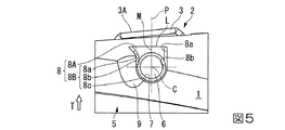
なお、本実施形態では、図4に示したように凹部8の底面8Aと工具本体1の外面(先端部の外周面)との交差稜線Lの両端部に連なる壁面8Bの2つの第1の壁面部8aの双方が、それぞれの連なる交差稜線Lの端部に向かうに従い上記仮想平面Pとの間隔が大きくなるように形成されているが、これら2つの第1の壁面部8aのうち一方は、この一方の第1の壁面部8aが連なる交差稜線Lの一方の端部に向けて仮想平面Pとの間隔が大きくなるものの、他方の第1の壁面部8aは交差稜線Lの他方の端部に向けて、仮想平面Pとの間隔が大きくはならず、かといって小さくもならずに、ネジ穴中心線Cに沿って凹部8の底面8Aに対向する方向から見たときに、図5または図6に示す変形例のように仮想平面Pと平行に延びていてもよい。
In the present embodiment, as shown in FIG. 4, the two first wall surfaces 8 </ b> B are connected to both end portions of the intersecting ridge line L between the
ここで、図5に示す第1の変形例では、2つの第1の壁面部8aのうち工具本体1の先端側の一方の第1の壁面部8aが交差稜線Lの一方の端部に向けてネジ穴中心線C方向視に仮想平面Pとの間隔が漸次大きくなるように形成され、工具本体1後端側の他方の第1の壁面部8aは、これに連なる第2の壁面部8bと面一な延長面として仮想平面Pと平行に延びている。また、図6に示す第2の変形例では、第1の変形例とは逆に工具本体1後端側が一方の第1の壁面部8aとされて、工具本体1後端側の交差稜線Lの一方の端部に向けて仮想平面Pとの間隔が漸次大きくなるように形成され、工具本体1先端側の他方の第1の壁面部8aが仮想平面Pと平行に延びている。
Here, in the first modified example shown in FIG. 5, one of the two first wall surfaces 8 a on the tip side of the
このような第1、第2の変形例の刃先交換式切削工具においても、2つの第1の壁面部8aのうちいずれか一方の第1の壁面部8aは、該一方の第1の壁面部8aが連なる交差稜線Lの一方の端部に向かうに従い仮想平面Pとの間隔が漸次大きくなるように形成されているので、この一方の端部側に応力を分散させて応力集中を避けることができ、クラックの発生を防止することができる。
Also in the blade-tip-exchangeable cutting tools of the first and second modified examples, any one of the two
また、上記実施形態やその第1、第2の変形例では、2つの第1の壁面部8aのうち該第1の壁面部8aが交差する上記交差稜線Lの端部に向かうに従い仮想平面Pとの間隔が漸次大きくなる第1の壁面部8a(図1ないし図4に示す実施形態では双方の第1の壁面部8a。図5に示す第1の変形例では工具本体1先端側の一方の第1の壁面部8a。図6に示す第2の変形例では工具本体1後端側の一方の第1の壁面部8a。)が、ネジ穴中心線Cに沿って底面8Aに対向する方向から見たときに凸曲線状をなして上記仮想平面Pとの間隔が大きくなった後に、この凸曲線に接する直線状をなして仮想平面Pとの間隔がさらに大きくなるように形成されているが、例えば凸曲線をなしたまま交差稜線Lの端部に交差するように形成されていてもよい。
Moreover, in the said embodiment and its 1st, 2nd modification, the virtual plane P is approached to the edge part of the said intersection ridgeline L which this 1st
さらに、同じく交差稜線Lの端部に向かうに従い仮想平面Pとの間隔が漸次大きくなる第1の壁面部8aは、仮想平面Pに平行な第2の壁面部8bを介して凹円筒面状の第3の壁面部8cに連なっているが、このような第2の壁面部8bを介することなく、凹円筒面状の第3の壁面部8cに、ネジ穴中心線Cに沿って見たときに第1の壁面部8aの凸曲線状をなす部分が直接接するように形成されていてもよい。
Further, the first
さらにまた、2つの第1の壁面部8aの双方が交差稜線Lの両端部に向かうに従い仮想平面Pとの間隔が漸次大きくなるようにされた図1ないし図4に示した実施形態では、凹部8が仮想平面Pに関して略面対称に形成されていて、これらの第1の壁面部8aも仮想平面Pに関して対称形状となるようにして仮想平面Pとの間隔が大きくなるようにされているが、同様に2つの第1の壁面部8aの双方が交差稜線Lの両端部に向かうに従い仮想平面Pとの間隔が漸次大きくなるようにされるにしても、例えば交差稜線Lの工具本体1先端側の端部と仮想平面Pとの間隔が後端側の端部との間隔よりも大きくされていたり、逆に公差稜線Lの工具本体1後端側の端部と仮想平面Pとの間隔が先端側の端部との間隔よりも大きくされていたりして、一方の第1の壁面部8aと他方の第1の壁面部8aとが仮想平面Pに関しては非対称となるように形成されていてもよい。
Furthermore, in the embodiment shown in FIGS. 1 to 4 in which both of the two first
1 工具本体
2 インサート取付座
3 切削インサート
6 クランプネジ
7 クランプネジ穴
8 凹部
8A 凹部8の底面
8B 凹部8の壁面
8a 壁面8Bの第1の壁面部(交差稜線Lの端部に連なる壁面部)
8b 壁面8Bの第2の壁面部
8c 壁面8Bの第3の壁面部
O 工具本体の軸線
T 工具回転方向
C クランプネジ穴7のネジ穴中心線
L 凹部8の底面8Aと工具本体1の外面(外周面)との交差稜線
M ネジ穴中心線Cに沿って凹部8の底面8Aに対向する方向から見たときに交差稜線Lとネジ穴中心線Cとを最短で結ぶ直線
P 直線Mとネジ穴中心線Cとを含む仮想平面
DESCRIPTION OF
8b Second wall surface portion of
Claims (5)
上記工具本体には、上記インサート取付座から延びて上記クランプネジがねじ込まれるクランプネジ穴と、上記インサート取付座に対してこのクランプネジ穴を間にして該工具本体の外面に開口する凹部とが形成され、
上記凹部は、上記外面に交差して上記クランプネジ穴が開口する底面と、この底面から上記クランプネジ穴のネジ穴中心線が延びる方向に延びて上記外面に交差する壁面とを備え、
上記壁面は、上記外面と上記底面との交差稜線の両端部にそれぞれ連なる2つの壁面部を有し、
上記ネジ穴中心線に沿って上記底面に対向する方向から見たときに上記交差稜線と上記ネジ穴中心線とを最短で結ぶ直線と該ネジ穴中心線とを含む仮想平面に対して、上記2つの壁面部のうち少なくとも一方の壁面部は、この一方の壁面部が連なる上記交差稜線の一方の端部に向かうに従い上記仮想平面との間隔が漸次大きくなるように形成され、他方の壁面部は、この他方の壁面部が連なる上記交差稜線の他方の端部に向かうに従い上記仮想平面との間隔が小さくならないように形成されていることを特徴とする刃先交換式切削工具。 A cutting edge exchangeable cutting tool in which a cutting insert is detachably attached to an insert mounting seat formed on a tool body by a clamp screw,
The tool body has a clamp screw hole extending from the insert mounting seat and into which the clamp screw is screwed, and a recess opening on the outer surface of the tool body with the clamp screw hole interposed between the insert mounting seat and the tool body. Formed,
The recess includes a bottom surface that intersects the outer surface and the clamp screw hole is opened, and a wall surface that extends from the bottom surface in a direction in which a screw hole center line of the clamp screw hole extends and intersects the outer surface,
The wall surface has two wall surface portions respectively connected to both end portions of the intersecting ridge line between the outer surface and the bottom surface,
With respect to a virtual plane including the screw hole center line and the straight line connecting the intersecting ridge line and the screw hole center line when viewed from the direction facing the bottom surface along the screw hole center line, At least one wall surface portion of the two wall surface portions is formed such that the distance from the virtual plane gradually increases toward one end portion of the intersecting ridge line where the one wall surface portion continues, and the other wall surface portion Is formed so that the distance from the virtual plane does not become smaller toward the other end portion of the intersecting ridge line where the other wall surface portion is continuous.
Priority Applications (1)
| Application Number | Priority Date | Filing Date | Title |
|---|---|---|---|
| JP2013265659A JP6201735B2 (en) | 2013-12-24 | 2013-12-24 | Replaceable cutting tool |
Applications Claiming Priority (1)
| Application Number | Priority Date | Filing Date | Title |
|---|---|---|---|
| JP2013265659A JP6201735B2 (en) | 2013-12-24 | 2013-12-24 | Replaceable cutting tool |
Publications (2)
| Publication Number | Publication Date |
|---|---|
| JP2015120223A JP2015120223A (en) | 2015-07-02 |
| JP6201735B2 true JP6201735B2 (en) | 2017-09-27 |
Family
ID=53532367
Family Applications (1)
| Application Number | Title | Priority Date | Filing Date |
|---|---|---|---|
| JP2013265659A Active JP6201735B2 (en) | 2013-12-24 | 2013-12-24 | Replaceable cutting tool |
Country Status (1)
| Country | Link |
|---|---|
| JP (1) | JP6201735B2 (en) |
Families Citing this family (2)
| Publication number | Priority date | Publication date | Assignee | Title |
|---|---|---|---|---|
| US9764397B2 (en) * | 2014-02-26 | 2017-09-19 | Tungaloy Corporation | Indexable rotary cutting tool |
| WO2023176533A1 (en) * | 2022-03-14 | 2023-09-21 | 京セラ株式会社 | Rotating tool and production method for cut workpiece |
Family Cites Families (4)
| Publication number | Priority date | Publication date | Assignee | Title |
|---|---|---|---|---|
| JPS59183720U (en) * | 1983-05-23 | 1984-12-07 | 東芝タンガロイ株式会社 | Throw-away roughing end mill |
| JP4639881B2 (en) * | 2005-03-24 | 2011-02-23 | 株式会社タンガロイ | Throw-away cutting tool |
| SE530629C2 (en) * | 2006-12-12 | 2008-07-22 | Sandvik Intellectual Property | Tools and basic body for chip separating machining including an elastically deformable spring in the cutting position |
| JP2013202770A (en) * | 2012-03-29 | 2013-10-07 | Mitsubishi Materials Corp | Blade edge replaceable end mill and end mill main body used for the same |
-
2013
- 2013-12-24 JP JP2013265659A patent/JP6201735B2/en active Active
Also Published As
| Publication number | Publication date |
|---|---|
| JP2015120223A (en) | 2015-07-02 |
Similar Documents
| Publication | Publication Date | Title |
|---|---|---|
| JP5906976B2 (en) | Cutting insert and cutting edge changeable cutting tool | |
| JP5475808B2 (en) | Rotating tools and cutting inserts for cutting | |
| JP5491505B2 (en) | Milling and cutting tips therefor | |
| JP6365363B2 (en) | Cutting insert, cutting insert group and cutting edge exchangeable cutting tool | |
| JP6205726B2 (en) | Cutting inserts for face milling and exchangeable face milling | |
| WO2014148515A1 (en) | Cutting insert, and cutting tool with replaceable cutting edge | |
| WO2016140333A1 (en) | Cutting insert and cutting edge-replaceable rotary cutting tool | |
| WO2015098646A1 (en) | Drill insert and indexable drill | |
| JP6361948B2 (en) | Cutting inserts and cutting tools | |
| JP5938868B2 (en) | Cutting insert and cutting edge changeable cutting tool | |
| WO2012118009A1 (en) | Cutting insert | |
| JP2014083667A (en) | Cutting insert and tip replaceable cutting tool | |
| JP4983352B2 (en) | Cutting insert and insert detachable rolling tool | |
| WO2014021314A1 (en) | Cutting insert, and replaceable-blade-edge cutting tool | |
| JP2009291925A (en) | Cutting insert and insert detachable cutting tool | |
| JP4821244B2 (en) | Throw-away tip and throw-away end mill | |
| JP6201735B2 (en) | Replaceable cutting tool | |
| JP4952068B2 (en) | Throw-away rotary tool | |
| JP2014200878A (en) | Cutting insert and tip replaceable cutting tool | |
| JP4940863B2 (en) | Throw-away rotary tool | |
| JP5664409B2 (en) | Replaceable edge luffing end mill | |
| JP2020116707A (en) | Blade edge replaceable end mill | |
| JP2013121642A (en) | Cutting insert and indexable end mill | |
| JP4952171B2 (en) | Throw-away rotary tool | |
| JP2013121640A (en) | Cutting insert and indexable end mill |
Legal Events
| Date | Code | Title | Description |
|---|---|---|---|
| A621 | Written request for application examination |
Free format text: JAPANESE INTERMEDIATE CODE: A621 Effective date: 20160929 |
|
| A977 | Report on retrieval |
Free format text: JAPANESE INTERMEDIATE CODE: A971007 Effective date: 20170714 |
|
| TRDD | Decision of grant or rejection written | ||
| A01 | Written decision to grant a patent or to grant a registration (utility model) |
Free format text: JAPANESE INTERMEDIATE CODE: A01 Effective date: 20170801 |
|
| A61 | First payment of annual fees (during grant procedure) |
Free format text: JAPANESE INTERMEDIATE CODE: A61 Effective date: 20170814 |
|
| R150 | Certificate of patent or registration of utility model |
Ref document number: 6201735 Country of ref document: JP Free format text: JAPANESE INTERMEDIATE CODE: R150 |