KR20220130218A - lifting of containers - Google Patents
lifting of containers Download PDFInfo
- Publication number
- KR20220130218A KR20220130218A KR1020227029051A KR20227029051A KR20220130218A KR 20220130218 A KR20220130218 A KR 20220130218A KR 1020227029051 A KR1020227029051 A KR 1020227029051A KR 20227029051 A KR20227029051 A KR 20227029051A KR 20220130218 A KR20220130218 A KR 20220130218A
- Authority
- KR
- South Korea
- Prior art keywords
- container
- handling device
- assembly
- load
- spools
- Prior art date
Links
- 238000003860 storage Methods 0.000 claims abstract description 75
- 238000000034 method Methods 0.000 claims abstract description 37
- 230000007246 mechanism Effects 0.000 claims abstract description 36
- 238000004891 communication Methods 0.000 claims description 17
- 230000008878 coupling Effects 0.000 claims description 5
- 238000010168 coupling process Methods 0.000 claims description 5
- 238000005859 coupling reaction Methods 0.000 claims description 5
- 230000008901 benefit Effects 0.000 description 19
- 230000000712 assembly Effects 0.000 description 16
- 238000000429 assembly Methods 0.000 description 16
- 230000008859 change Effects 0.000 description 6
- 230000003028 elevating effect Effects 0.000 description 6
- 238000004804 winding Methods 0.000 description 6
- 230000007257 malfunction Effects 0.000 description 5
- 230000006870 function Effects 0.000 description 4
- 230000005540 biological transmission Effects 0.000 description 2
- 230000002950 deficient Effects 0.000 description 2
- 230000006872 improvement Effects 0.000 description 2
- 230000009467 reduction Effects 0.000 description 2
- 230000008439 repair process Effects 0.000 description 2
- 230000009471 action Effects 0.000 description 1
- 230000004323 axial length Effects 0.000 description 1
- 238000004590 computer program Methods 0.000 description 1
- 238000010276 construction Methods 0.000 description 1
- 230000007547 defect Effects 0.000 description 1
- 230000004069 differentiation Effects 0.000 description 1
- 238000003754 machining Methods 0.000 description 1
- 238000012423 maintenance Methods 0.000 description 1
- 238000004519 manufacturing process Methods 0.000 description 1
- 230000013011 mating Effects 0.000 description 1
- 238000004806 packaging method and process Methods 0.000 description 1
- 230000001360 synchronised effect Effects 0.000 description 1
- 238000003466 welding Methods 0.000 description 1
Images


Classifications
-
- B—PERFORMING OPERATIONS; TRANSPORTING
- B65—CONVEYING; PACKING; STORING; HANDLING THIN OR FILAMENTARY MATERIAL
- B65G—TRANSPORT OR STORAGE DEVICES, e.g. CONVEYORS FOR LOADING OR TIPPING, SHOP CONVEYOR SYSTEMS OR PNEUMATIC TUBE CONVEYORS
- B65G1/00—Storing articles, individually or in orderly arrangement, in warehouses or magazines
- B65G1/02—Storage devices
- B65G1/04—Storage devices mechanical
- B65G1/0464—Storage devices mechanical with access from above
-
- B—PERFORMING OPERATIONS; TRANSPORTING
- B60—VEHICLES IN GENERAL
- B60L—PROPULSION OF ELECTRICALLY-PROPELLED VEHICLES; SUPPLYING ELECTRIC POWER FOR AUXILIARY EQUIPMENT OF ELECTRICALLY-PROPELLED VEHICLES; ELECTRODYNAMIC BRAKE SYSTEMS FOR VEHICLES IN GENERAL; MAGNETIC SUSPENSION OR LEVITATION FOR VEHICLES; MONITORING OPERATING VARIABLES OF ELECTRICALLY-PROPELLED VEHICLES; ELECTRIC SAFETY DEVICES FOR ELECTRICALLY-PROPELLED VEHICLES
- B60L50/00—Electric propulsion with power supplied within the vehicle
- B60L50/50—Electric propulsion with power supplied within the vehicle using propulsion power supplied by batteries or fuel cells
- B60L50/60—Electric propulsion with power supplied within the vehicle using propulsion power supplied by batteries or fuel cells using power supplied by batteries
-
- B—PERFORMING OPERATIONS; TRANSPORTING
- B60—VEHICLES IN GENERAL
- B60L—PROPULSION OF ELECTRICALLY-PROPELLED VEHICLES; SUPPLYING ELECTRIC POWER FOR AUXILIARY EQUIPMENT OF ELECTRICALLY-PROPELLED VEHICLES; ELECTRODYNAMIC BRAKE SYSTEMS FOR VEHICLES IN GENERAL; MAGNETIC SUSPENSION OR LEVITATION FOR VEHICLES; MONITORING OPERATING VARIABLES OF ELECTRICALLY-PROPELLED VEHICLES; ELECTRIC SAFETY DEVICES FOR ELECTRICALLY-PROPELLED VEHICLES
- B60L58/00—Methods or circuit arrangements for monitoring or controlling batteries or fuel cells, specially adapted for electric vehicles
- B60L58/10—Methods or circuit arrangements for monitoring or controlling batteries or fuel cells, specially adapted for electric vehicles for monitoring or controlling batteries
- B60L58/24—Methods or circuit arrangements for monitoring or controlling batteries or fuel cells, specially adapted for electric vehicles for monitoring or controlling batteries for controlling the temperature of batteries
- B60L58/26—Methods or circuit arrangements for monitoring or controlling batteries or fuel cells, specially adapted for electric vehicles for monitoring or controlling batteries for controlling the temperature of batteries by cooling
-
- B—PERFORMING OPERATIONS; TRANSPORTING
- B60—VEHICLES IN GENERAL
- B60R—VEHICLES, VEHICLE FITTINGS, OR VEHICLE PARTS, NOT OTHERWISE PROVIDED FOR
- B60R16/00—Electric or fluid circuits specially adapted for vehicles and not otherwise provided for; Arrangement of elements of electric or fluid circuits specially adapted for vehicles and not otherwise provided for
- B60R16/02—Electric or fluid circuits specially adapted for vehicles and not otherwise provided for; Arrangement of elements of electric or fluid circuits specially adapted for vehicles and not otherwise provided for electric constitutive elements
- B60R16/04—Arrangement of batteries
-
- B—PERFORMING OPERATIONS; TRANSPORTING
- B65—CONVEYING; PACKING; STORING; HANDLING THIN OR FILAMENTARY MATERIAL
- B65G—TRANSPORT OR STORAGE DEVICES, e.g. CONVEYORS FOR LOADING OR TIPPING, SHOP CONVEYOR SYSTEMS OR PNEUMATIC TUBE CONVEYORS
- B65G1/00—Storing articles, individually or in orderly arrangement, in warehouses or magazines
- B65G1/02—Storage devices
- B65G1/04—Storage devices mechanical
- B65G1/0478—Storage devices mechanical for matrix-arrangements
-
- B—PERFORMING OPERATIONS; TRANSPORTING
- B65—CONVEYING; PACKING; STORING; HANDLING THIN OR FILAMENTARY MATERIAL
- B65G—TRANSPORT OR STORAGE DEVICES, e.g. CONVEYORS FOR LOADING OR TIPPING, SHOP CONVEYOR SYSTEMS OR PNEUMATIC TUBE CONVEYORS
- B65G1/00—Storing articles, individually or in orderly arrangement, in warehouses or magazines
- B65G1/02—Storage devices
- B65G1/04—Storage devices mechanical
- B65G1/0485—Check-in, check-out devices
-
- B—PERFORMING OPERATIONS; TRANSPORTING
- B65—CONVEYING; PACKING; STORING; HANDLING THIN OR FILAMENTARY MATERIAL
- B65G—TRANSPORT OR STORAGE DEVICES, e.g. CONVEYORS FOR LOADING OR TIPPING, SHOP CONVEYOR SYSTEMS OR PNEUMATIC TUBE CONVEYORS
- B65G1/00—Storing articles, individually or in orderly arrangement, in warehouses or magazines
- B65G1/02—Storage devices
- B65G1/04—Storage devices mechanical
- B65G1/0492—Storage devices mechanical with cars adapted to travel in storage aisles
-
- B—PERFORMING OPERATIONS; TRANSPORTING
- B65—CONVEYING; PACKING; STORING; HANDLING THIN OR FILAMENTARY MATERIAL
- B65G—TRANSPORT OR STORAGE DEVICES, e.g. CONVEYORS FOR LOADING OR TIPPING, SHOP CONVEYOR SYSTEMS OR PNEUMATIC TUBE CONVEYORS
- B65G1/00—Storing articles, individually or in orderly arrangement, in warehouses or magazines
- B65G1/02—Storage devices
- B65G1/04—Storage devices mechanical
- B65G1/06—Storage devices mechanical with means for presenting articles for removal at predetermined position or level
- B65G1/065—Storage devices mechanical with means for presenting articles for removal at predetermined position or level with self propelled cars
-
- B—PERFORMING OPERATIONS; TRANSPORTING
- B65—CONVEYING; PACKING; STORING; HANDLING THIN OR FILAMENTARY MATERIAL
- B65G—TRANSPORT OR STORAGE DEVICES, e.g. CONVEYORS FOR LOADING OR TIPPING, SHOP CONVEYOR SYSTEMS OR PNEUMATIC TUBE CONVEYORS
- B65G1/00—Storing articles, individually or in orderly arrangement, in warehouses or magazines
- B65G1/02—Storage devices
- B65G1/04—Storage devices mechanical
- B65G1/137—Storage devices mechanical with arrangements or automatic control means for selecting which articles are to be removed
- B65G1/1373—Storage devices mechanical with arrangements or automatic control means for selecting which articles are to be removed for fulfilling orders in warehouses
-
- B—PERFORMING OPERATIONS; TRANSPORTING
- B66—HOISTING; LIFTING; HAULING
- B66C—CRANES; LOAD-ENGAGING ELEMENTS OR DEVICES FOR CRANES, CAPSTANS, WINCHES, OR TACKLES
- B66C19/00—Cranes comprising trolleys or crabs running on fixed or movable bridges or gantries
-
- H—ELECTRICITY
- H01—ELECTRIC ELEMENTS
- H01M—PROCESSES OR MEANS, e.g. BATTERIES, FOR THE DIRECT CONVERSION OF CHEMICAL ENERGY INTO ELECTRICAL ENERGY
- H01M10/00—Secondary cells; Manufacture thereof
- H01M10/60—Heating or cooling; Temperature control
- H01M10/61—Types of temperature control
- H01M10/613—Cooling or keeping cold
-
- H—ELECTRICITY
- H01—ELECTRIC ELEMENTS
- H01M—PROCESSES OR MEANS, e.g. BATTERIES, FOR THE DIRECT CONVERSION OF CHEMICAL ENERGY INTO ELECTRICAL ENERGY
- H01M10/00—Secondary cells; Manufacture thereof
- H01M10/60—Heating or cooling; Temperature control
- H01M10/62—Heating or cooling; Temperature control specially adapted for specific applications
- H01M10/625—Vehicles
-
- H—ELECTRICITY
- H01—ELECTRIC ELEMENTS
- H01M—PROCESSES OR MEANS, e.g. BATTERIES, FOR THE DIRECT CONVERSION OF CHEMICAL ENERGY INTO ELECTRICAL ENERGY
- H01M10/00—Secondary cells; Manufacture thereof
- H01M10/60—Heating or cooling; Temperature control
- H01M10/65—Means for temperature control structurally associated with the cells
- H01M10/655—Solid structures for heat exchange or heat conduction
- H01M10/6551—Surfaces specially adapted for heat dissipation or radiation, e.g. fins or coatings
-
- H—ELECTRICITY
- H01—ELECTRIC ELEMENTS
- H01M—PROCESSES OR MEANS, e.g. BATTERIES, FOR THE DIRECT CONVERSION OF CHEMICAL ENERGY INTO ELECTRICAL ENERGY
- H01M10/00—Secondary cells; Manufacture thereof
- H01M10/60—Heating or cooling; Temperature control
- H01M10/65—Means for temperature control structurally associated with the cells
- H01M10/656—Means for temperature control structurally associated with the cells characterised by the type of heat-exchange fluid
- H01M10/6561—Gases
- H01M10/6563—Gases with forced flow, e.g. by blowers
-
- H—ELECTRICITY
- H01—ELECTRIC ELEMENTS
- H01M—PROCESSES OR MEANS, e.g. BATTERIES, FOR THE DIRECT CONVERSION OF CHEMICAL ENERGY INTO ELECTRICAL ENERGY
- H01M10/00—Secondary cells; Manufacture thereof
- H01M10/60—Heating or cooling; Temperature control
- H01M10/65—Means for temperature control structurally associated with the cells
- H01M10/657—Means for temperature control structurally associated with the cells by electric or electromagnetic means
- H01M10/6572—Peltier elements or thermoelectric devices
-
- B—PERFORMING OPERATIONS; TRANSPORTING
- B65—CONVEYING; PACKING; STORING; HANDLING THIN OR FILAMENTARY MATERIAL
- B65G—TRANSPORT OR STORAGE DEVICES, e.g. CONVEYORS FOR LOADING OR TIPPING, SHOP CONVEYOR SYSTEMS OR PNEUMATIC TUBE CONVEYORS
- B65G2201/00—Indexing codes relating to handling devices, e.g. conveyors, characterised by the type of product or load being conveyed or handled
- B65G2201/02—Articles
- B65G2201/0235—Containers
-
- Y—GENERAL TAGGING OF NEW TECHNOLOGICAL DEVELOPMENTS; GENERAL TAGGING OF CROSS-SECTIONAL TECHNOLOGIES SPANNING OVER SEVERAL SECTIONS OF THE IPC; TECHNICAL SUBJECTS COVERED BY FORMER USPC CROSS-REFERENCE ART COLLECTIONS [XRACs] AND DIGESTS
- Y02—TECHNOLOGIES OR APPLICATIONS FOR MITIGATION OR ADAPTATION AGAINST CLIMATE CHANGE
- Y02T—CLIMATE CHANGE MITIGATION TECHNOLOGIES RELATED TO TRANSPORTATION
- Y02T90/00—Enabling technologies or technologies with a potential or indirect contribution to GHG emissions mitigation
- Y02T90/10—Technologies relating to charging of electric vehicles
- Y02T90/12—Electric charging stations
Abstract
컨테이너(9)를 상승시키고 이동시키기 위한 로드-핸들링 디바이스(31)가 제공되며, 로드-핸들링 디바이스(31)는, 상부(45) 및 하부(47)를 갖는 본체(33) - 상부(45)는 하나 이상의 작동 컴포넌트를 수용하도록 구성되고, 하부(47)는 상부(45) 아래에 배치되고, 하부는 컨테이너(9)의 적어도 일부를 수용하기 위한 컨테이너-수용 공간을 포함함 -; 및 컨테이너(9)를 해제 가능하게 파지하도록 구성된 컨테이너 - 그리핑 어셈블리(43) 및 컨테이너-그리핑 어셈블리(43)를 상승 및 하강시키도록 구성된 승강 어셈블리(51)를 포함하는 컨테이너-리프팅 메커니즘을 포함하고, 상기 승강 어셈블리(51)는 컨테이너 그리핑 어셈블리(43)를 상승 및 하강시키도록 구성된 단일 모터(52)를 포함한다. 대응하는 방법, 컴퓨터-판독 가능한 저장 매체와 보관 및 회수 시스템이 또한 제공된다.A load-handling device 31 for lifting and moving the container 9 is provided, the load-handling device 31 comprising: a body 33 having an upper part 45 and a lower part 47 - an upper part 45 is configured to receive one or more actuating components, the lower portion 47 being disposed below the upper portion 45, the lower portion comprising a container-receiving space for accommodating at least a portion of the container 9; and a container-lifting mechanism comprising a container-gripping assembly 43 configured to releasably grip the container 9 and a lifting assembly 51 configured to raise and lower the container-gripping assembly 43 . and the lifting assembly 51 includes a single motor 52 configured to raise and lower the container gripping assembly 43 . Corresponding methods, computer-readable storage media and storage and retrieval systems are also provided.
Description
본 발명은 컨테이너의 상승 및 하강에 관한 것이다. 특히, 이는 로드-핸들링 디바이스의 본체에 대해 컨테이너를 승강시키기 위한 로드-핸들링 디바이스(load-handling devices), 방법, 컴퓨터-판독 가능한 저장 매체, 및 보관 및 회수 시스템에 관한 것이다.The present invention relates to the raising and lowering of containers. In particular, it relates to load-handling devices, methods, computer-readable storage media, and storage and retrieval systems for elevating containers relative to the body of the load-handling device.
청구된 장치, 방법, 시스템 및 컴퓨터 프로그램은 로드-핸들링 디바이스의 본체에 대한 컨테이너의 상승 및 하강과 관련된 개선을 제공하기 위한 것이다. 이들은 특히, 반드시 배타적이지는 않지만, 다수의 로드-핸들링 디바이스가 보관 구조체에 대해 상이한 위치에서 보관 컨테이너를 수집하거나 하강시키기 위해 그 위에서 이동할 수 있는 보관 구조체와 함께 사용될 수 있는 보관 컨테이너의 상승 및 하강과 관련된 개선을 제공하도록 의도된다.The claimed apparatus, method, system and computer program are intended to provide improvements related to the lifting and lowering of containers relative to the body of a load-handling device. These are in particular, but not necessarily exclusive to, raising and lowering of a storage container, where a number of load-handling devices can be used with a storage structure that can be moved thereon to collect or lower the storage container at different positions relative to the storage structure. It is intended to provide related improvements.
일 실시 형태에 따르면, 청구항 1에 청구된 바와 같은 로드-핸들링 디바이스가 제공된다.According to one embodiment, there is provided a load-handling device as claimed in
다른 실시 형태에 따르면, 청구항 20에 청구된 바와 같은 방법이 제공된다.According to another embodiment, there is provided a method as claimed in claim 20 .
다른 실시 형태에 따르면, 컴퓨터-판독 가능한 저장 매체가 제공된다.According to another embodiment, a computer-readable storage medium is provided.
다른 실시 형태에 따르면, 청구항 26에 청구된 바와 같은 보관 및 회수 시스템이 제공된다.According to another embodiment, there is provided a storage and retrieval system as claimed in claim 26 .
본 출원은 2020년 1월 24일에 출원된 영국 특허 출원 번호 GB2001012.0호 및 2020년 3월 4일에 출원된 GB2003101.9호의 우선권을 주장하며, 이들 출원의 내용은 원용에 의해 본 명세서에 참조로 포함된다.This application claims priority to UK Patent Application No. GB2001012.0, filed on January 24, 2020, and GB2003101.9, filed on March 4, 2020, the contents of which are incorporated herein by reference. incorporated by reference.
본 출원의 한 가지 목적은 내결함성 또는 내고장성 로드-핸들링 디바이스(load-handling device)를 제공하는 것이다. 본 발명의 다른 목적은 결함 또는 고장이 감지되거나 발생되는 경우 자체-복구 또는 적어도 부분적으로 자체-복구할 수 있는 로드-핸들링 디바이스를 제공하는 것이다.One object of the present application is to provide a fault-tolerant or fault-tolerant load-handling device. Another object of the present invention is to provide a load-handling device capable of self-healing or at least partially self-recovering when a fault or failure is detected or occurs.
복수의 그리드 공간들을 포함하는 그리드 패턴(grid pattern)을 형성하기 위해, 제 1 세트의 평행 레일들 또는 트랙들 및 실질적으로 수평인 평면에서 제 1 세트의 레일들 또는 트랙들에 실질적으로 수직으로 연장되는 제 2 세트의 평행 레일들 또는 트랙들을, 포함하는 그리드 프레임워크 구조체(grid framework structure)에 적층된 보관 컨테이너를 승강시키고 이동시키기 위한 로드-핸들링 디바이스가 제공되고, 상기 그리드는 그리드 아래에 복수의 수직 보관 위치들을 형성하기 위해 한 세트의 직립체들에 의해 지지되어 컨테이너들이 직립체들 사이에 적층되고 직립체들에 의해 복수의 그리드 공간들을 통해 수직 방향으로 안내되고, 로드-핸들링 디바이스는, 제 1 세트의 평행 트랙들과 결합하도록 배치된 제 1 세트의 휠들 및 제 2 세트의 평행 트랙들과 결합하도록 배치된 제 2 세트의 휠들에 장착된 본체, 및 상기 로드-핸들링 디바이스를 제 1 세트의 평행 트랙들을 따라 제 1 방향으로 구동하거나 상기 로드-핸들링 디바이스를 제 2 세트의 평행 트랙들을 따라 제 2 방향으로 구동하기 위한 구동 어셈블리를 포함하고, 상기 구동 어셈블리는, 제 1 세트의 휠들을 구동하기 위한 적어도 2개의 모터들; 제 2 세트의 휠들을 구동하기 위한 적어도 2개의 모터들; 및 모터들로부터 휠들로 구동력을 전달하기 위한 모터들의 수에 대응하는 다수의 기어 장치들을 포함하고, 상기 모터들은 종동 휠에 수직이고 구동 휠의 회전축에 평행한 면에 배치되고, 상기 모터의 구동 샤프트는 상기 면을 따라 연장된다.extending substantially perpendicular to the first set of parallel rails or tracks and the first set of rails or tracks in a substantially horizontal plane to form a grid pattern comprising a plurality of grid spaces A load-handling device is provided for elevating and moving a storage container stacked on a grid framework structure comprising a second set of parallel rails or tracks being Supported by a set of uprights to form vertical storage positions wherein the containers are stacked between the uprights and guided vertically through a plurality of grid spaces by the uprights, the load-handling device comprising: a body mounted to a first set of wheels arranged to engage a set of parallel tracks and a second set of wheels arranged to engage a second set of parallel tracks, and the load-handling device to a first set of a drive assembly for driving the rod-handling device in a first direction along parallel tracks or driving the rod-handling device in a second direction along a second set of parallel tracks, the drive assembly comprising: at least two motors for at least two motors for driving the second set of wheels; and a plurality of gear devices corresponding to the number of motors for transmitting driving force from the motors to the wheels, wherein the motors are disposed in a plane perpendicular to the driven wheel and parallel to the axis of rotation of the driving wheel, the drive shaft of the motor extends along the plane.
이러한 방식으로, 로드-핸들링 디바이스는 제 1 또는 x-방향으로 이동하거나 제 2 또는 y-방향으로 이동하도록 제1 세트의 휠들과 제2 세트의 휠들에 선택적으로 동력을 공급하거나 구동함으로써 트랙을 따라 모든 그리드 공간들로 이동할 수 있다. 종동 휠은 정방향 및 역방향으로 구동될 수 있다. 이동 방향과 그리드 패턴 자체의 유연성은 로드-핸들링 디바이스가 특정 그리드 위치로 특정 경로를 이동할 필요가 없다는 것을 의미하며, 대신에 로드-핸들링 디바이스는 그리드 상의 장애물 주위, 예를 들어 다른 로드 핸들링 디바이스 주위를 이동할 수 있다.In this way, the road-handling device follows the track by selectively energizing or driving the first set of wheels and the second set of wheels to move in the first or x-direction or in the second or y-direction. You can move to all grid spaces. The driven wheel can be driven in forward and reverse directions. The flexibility of the direction of travel and the grid pattern itself means that the load-handling device does not need to travel a specific path to a specific grid position, instead, the load-handling device moves around obstacles on the grid, for example around other load-handling devices. can move
구동 모터가 구동되는 휠에 수직인 면에 배치되는 이점은 모터가 로드-핸들링 디바이스의 면 내에 배치될 수 있다는 것, 즉 로드-핸들링 디바이스의 주변을 가로질러 연장될 수 있다는 것이다. 이러한 배치는 본체의 중앙 부분이 구동 모터 또는 구동 샤프트로부터 개방되거나 비어 있는 상태로 남겨져, 캐비티(cavity)를 남긴다는 것을 의미한다. 캐비티는 로드 핸들링 디바이스의 다른 컴포넌트를 수용하는 데 사용될 수 있다. 또는 캐비티는 상승된 보관 컨테이너를 수용하고, 로드-핸들링 디바이스가 그리드에서 다른 위치로 이동하는 동안 상승된 보관 컨테이너를 수용하는 데 사용될 수 있다.An advantage that the drive motor is arranged in a plane perpendicular to the wheel being driven is that the motor can be arranged in the plane of the rod-handling device, ie it can extend across the periphery of the rod-handling device. This arrangement means that the central portion of the body is left open or empty from the drive motor or drive shaft, leaving a cavity. The cavity may be used to accommodate other components of the load handling device. Alternatively, the cavity may be used to house the elevated storage container, and to receive the elevated storage container while the load-handling device is moved from the grid to another location.
구동 모터의 그러한 배치의 또 다른 이점은 구동 샤프트가 직접 구동 허브 모터 장치와 같이, 로드-핸들링 디바이스 본체를 가로질러 연장되지 않는 다른 모터 장치보다 상당히 길 수 있다는 것이다.Another advantage of such an arrangement of the drive motor is that the drive shaft can be significantly longer than other motor arrangements that do not extend across the rod-handling device body, such as a direct drive hub motor arrangement.
로드-핸들링 디바이스를 제 1 방향 또는 x-방향으로 구동하기 위한 적어도 2개의 모터들을 갖고 로드-핸들링 디바이스를 제 2 또는 y-방향으로 구동하기 위한 적어도 2개의 모터들을 가짐으로써, 로드-핸들링 디바이스를 양방향으로 구동하기 위한 이중화(redundancy)가 있음이 이해될 것이다. 유리하게는, 한 세트의 휠들 대해 하나의 모터의 고장이 있더라도 로드-핸들링 디바이스는 여전히 그리드의 에지 또는 수리 영역으로 "림프 홈(limp home)"할 수 있다. 유리하게는, 이는 결함이 있는 로드-핸들링 디바이스가 복구되고 수리되는 동안 그리드가 완전히 작동되는 것을 계속할 수 있고 결함이 있는 로드-핸들링 디바이스가 복구되는 동안 그리드 작동 중단에 대한 필요성을 감소시킨다는 것을 의미한다. 유리하게는 이것은 그리드가 효율적으로 작동될 수 있도록 보장하는 데 도움이 된다.By having at least two motors for driving the load-handling device in a first direction or x-direction and at least two motors for driving the rod-handling device in a second or y-direction, It will be appreciated that there is redundancy for running in both directions. Advantageously, even if one motor fails for a set of wheels, the load-handling device can still "limp home" to the edge of the grid or to the repair area. Advantageously, this means that the grid can continue to be fully operational while the defective load-handling device is restored and repaired and reduces the need for grid shutdown while the defective load-handling device is repaired . Advantageously, this helps to ensure that the grid can operate efficiently.
제 1 세트의 휠들은 로드-핸들링 디바이스의 제 1 면 상의 2개의 휠들, 및 로드-핸들링 디바이스의 제 1 대향 면 상의 2개의 휠들을 포함할 수 있으며; 제 2 세트의 휠들은 로드-핸들링 디바이스의 제 1 면에 수직인 로드-핸들링 디바이스의 면 상의 2개의 휠들, 및 로드-핸들링 디바이스의 제 2 대향 면 상의 2개의 휠들을 포함할 수 있고; 로드-핸들링 디바이스의 각 면 상의 적어도 하나의 휠은 각각의 모터에 의해 구동될 수 있다.The first set of wheels may include two wheels on a first side of the road-handling device, and two wheels on a first opposite side of the road-handling device; the second set of wheels may include two wheels on a side of the rod-handling device perpendicular to the first side of the rod-handling device, and two wheels on a second opposite side of the rod-handling device; At least one wheel on each side of the road-handling device may be driven by a respective motor.
구동 모터가 없는 휠들, 또는 비-구동 휠들은 로드-핸들링 디바이스가 휠 세트의 다른 휠들 의해 구동될 때 자유롭게 회전될 수 있는 아이들러 휠들(idler wheels)일 수 있다. 이러한 방식으로, 필요한 모터의 수가 감소되어, 자본의 비용, 로드-핸들링 디바이스의 공간 비용, 그리드 주위로 이동하도록 로드-핸들링 디바이스를 작동시키기 위해 부품을 동기화하는 데 필요한 통신 및 제어의 양이 절감된다.Wheels without a drive motor, or non-drive wheels, may be idler wheels that can be rotated freely when the road-handling device is driven by other wheels of the wheel set. In this way, the number of motors required is reduced, reducing the cost of capital, the space cost of the load-handling device, and the amount of communication and control needed to synchronize the parts to operate the load-handling device to move around the grid. .
로드-핸들링 디바이스의 각 측면 상의 하나의 휠이 구동되는 것이 이해될 것이다. It will be appreciated that one wheel on each side of the road-handling device is driven.
대향하는 측면 상의 종동 휠은 구동 중일 때 로드-핸들링 디바이스에 발생할 수 있는 임의의 비틀림력을 유리하게 제한하기 위해 서로 대각선으로 대향할 수 있다. 따라서, 이것은 로드-핸들링 디바이스가 트랙 한계(track limits)를 넘어 흔들릴 가능성을 적게 하고, 로드-핸들링 디바이스가 구동될 때 전복될 가능성을 적게 한다.The driven wheels on opposite sides may face each other diagonally in order to advantageously limit any torsional forces that may arise in the rod-handling device when driving. Thus, this makes the load-handling device less likely to swing beyond track limits and less likely to overturn when the load-handling device is driven.
제 1 세트의 휠들 및 제 2 세트의 휠들의 각 휠은 각각의 모터에 의해 구동될 수 있다.Each wheel of the first set of wheels and the second set of wheels may be driven by a respective motor.
휠들의 각각이 각각의 모터에 의해 구동될 수 있을 때 추가적인 이중화(redundancy)가 도입된다는 것이 이해될 것이다. 또한, 각 방향에 대해 2개의 모터에 비해 2배의 속도로, 각 방향에 대해 4개의 모터를 사용하여 로드-핸들링 디바이스를 구동하는 것이 가능할 수 있다는 것이 이해될 것이다. 또한, 모든 휠들을 각 방향으로 구동함으로써, 구동될 때 로드-핸들링 디바이스에 비틀림력을 도입할 가능성이 없어진다는 것으로 이해될 것이다.It will be appreciated that additional redundancy is introduced when each of the wheels can be driven by a respective motor. It will also be appreciated that it may be possible to drive the load-handling device using four motors for each direction, at twice the speed compared to two motors for each direction. It will also be appreciated that by driving all the wheels in each direction, the possibility of introducing a torsional force into the rod-handling device when driven is eliminated.
제 1 세트의 휠들 중 적어도 하나 및 제 2 세트의 휠들 중 적어도 하나는 제 1 전원에 의해 구동되는 모터(들)에 의해 구동될 수 있고, 제 1 세트의 휠들 중 적어도 하나 및 제 2 세트의 휠들 중 적어도 하나는 제 2 전원에 의해 모터(들)에 의해 구동될 수 있고, 제 1 전원 및 제 2 전원은 독립적이거나 별개이다.At least one of the first set of wheels and at least one of the second set of wheels may be driven by a motor(s) driven by a first power source, at least one of the first set of wheels and at least one of the second set of wheels at least one of which may be driven by the motor(s) by a second power source, the first power source and the second power source being independent or separate.
이러한 방식으로, 구동되어야 하는 휠들만이 언제든지 구동될 수 있다. 예를 들어, 모든 휠들이 트랙과 결합되면, 로드-핸들링 디바이스가 제 1 방향이나 제 2 방향으로 이동될 수 없으므로, 휠들 중 어느 것도 구동되어서는 안된다는 것이 이해될 것이다. 이러한 배치에서, 로드-핸들링 디바이스는 "파킹된(parked)" 구성에 있는 것으로 간주될 수 있다. 대안적으로 한 세트의 휠들이 트랙과 결합되지만, 결합된 세트의 휠들이 구동되지 않을 때, 로드-핸들링 디바이스는 파킹된 것으로 간주될 수 있다. 유리하게는 파킹된 구성에서 로드-핸들링 디바이스는 그리드에 있는 동안 정지될 수 있다. 일부 상황에서는 예를 들어, 그리드에서 작업을 수행할 위험을 줄이기 위해 그리드에서 작동하는 모든 로드-핸들링 디바이스들을 정지해야 할 수 있다.In this way, only the wheels that are to be driven can be driven at any time. For example, it will be understood that if all the wheels are engaged with the track, none of the wheels should be driven, as the road-handling device cannot be moved in either the first direction or the second direction. In this arrangement, the load-handling device may be considered to be in a “parked” configuration. Alternatively, the road-handling device may be considered parked when one set of wheels is engaged with the track, but the coupled set of wheels is not driven. Advantageously in the parked configuration the load-handling device can be stopped while on the grid. In some situations it may be necessary to stop all load-handling devices operating on the grid, for example to reduce the risk of performing work on the grid.
특정 이동 방향에 필요한 휠들만 구동될 수 있다는 것이 이해될 것이다. 유리하게는, 이것은 로드-핸들링 디바이스의 전원 공급 상의 부하를 감소시킬 수 있다.It will be appreciated that only the wheels necessary for a particular direction of movement may be driven. Advantageously, this can reduce the load on the power supply of the load-handling device.
제 1 세트의 휠들 중 2개와 제 2 세트의 휠들 중 2개는 제 1 전원에 의해 구동되는 모터들에 의해 구동되고, 제 1 세트의 휠들 중 2개 및 제 2 세트의 휠들 중 적어도 하나는 제 2 전원에 의해 전원이 공급되는 모터(들)에 의해 구동된다. 제 1 전원 및/또는 제 2 전원은 적어도 2개의 독립적인 부분으로 세분된다.Two of the first set of wheels and two of the second set of wheels are driven by motors driven by a first power source, two of the first set of wheels and at least one of the second set of wheels are 2 Powered by a motor(s) powered by a power source. The first power source and/or the second power source are subdivided into at least two independent parts.
이러한 방식으로, 하나의 전원 또는 전원의 부속 부품(sub-part)에 결함이 있더라도 로드-핸들링 디바이스는 감소된 용량으로 계속 작동될 수 있다.In this way, even if one power source or a sub-part of the power source fails, the load-handling device can continue to operate with a reduced capacity.
로드-핸들링 디바이스는 제 1 세트의 휠들 또는 제 2 세트의 휠들을 선택적으로 구동하기 위한 수단을 더 포함할 수 있다. 따라서, 모든 휠들이 특정 시간에 구동될 필요는 없다.The road-handling device may further comprise means for selectively driving the first set of wheels or the second set of wheels. Accordingly, it is not necessary for all wheels to be driven at a specific time.
로드-핸들링 디바이스는 제 1 세트의 휠들 및/또는 제 2 세트의 휠들을 제 1 세트의 트랙들 및 제 2 세트의 트랙들과 각각 선택적으로 결합하기 위한 방향 변경 어셈블리를 더 포함할 수 있다.The road-handling device may further comprise a direction change assembly for selectively coupling the first set of wheels and/or the second set of wheels with the first set of tracks and the second set of tracks, respectively.
유리하게는, 각 세트의 휠들은 제 1 및 제 2 방향으로 로드-핸들링 디바이스의 이동을 가능하게 하기 위해 트랙들과 선택적으로 결합될 수 있다. 로드-핸들링 디바이스는 또한 제 1 세트의 휠들과 제 2 세트의 휠들이 트랙들과 결합되는 파킹된 구성으로 이동될 수 있다.Advantageously, each set of wheels can be selectively engaged with tracks to enable movement of the rod-handling device in the first and second directions. The road-handling device may also be moved in a parked configuration in which the first set of wheels and the second set of wheels engage the tracks.
방향 변경 어셈블리는, 제 1 세트의 휠들을 위한 제 1 세트의 방향 변경 풀리들; 및 제 2 세트의 휠들을 위한 제 2 세트의 방향 변경 풀리들을 포함하고, 상기 방향 변경 풀리는 제 1 세트의 휠들 또는 제 2 세트의 휠들을 선택적으로 상승시키도록 작동되어 제 1 세트의 휠들 또는 제 2 세트의 휠들을 트랙들로부터 분리시킨다.The redirecting assembly includes: a first set of redirecting pulleys for a first set of wheels; and a second set of redirecting pulleys for a second set of wheels, wherein the redirecting pulley is operated to selectively raise the first set of wheels or the second set of wheels to selectively raise the first set of wheels or the second set of wheels. Separate the wheels of the set from the tracks.
이러한 방식으로, 각각의 휠들에 대한 방향 변경 어셈블리는 휠 위에 배치될 수 있고 휠들을 트랙들과 결합 및 분리하도록 휠들을 수직으로 이동시킬 수 있다. 휠들은 로드-핸들링 디바이스의 본체에 대해 이동될 수 있다. 적어도 일부의 휠들은 항상 트랙들과 결합되어 로드-핸들링 디바이스의 본체를 지지하게 될 것이라는 것이 이해될 것이다.In this way, a direction change assembly for each of the wheels can be disposed over the wheel and move the wheels vertically to engage and disengage the wheels from the tracks. The wheels can be moved relative to the body of the rod-handling device. It will be understood that at least some of the wheels will always be engaged with the tracks to support the body of the road-handling device.
이러한 방식으로, 제 1 세트의 휠들과 제 2 세트의 휠들은 모두 로드-핸들링 디바이스의 본체에 대해 수직 또는 z-방향으로 이동하도록 배치된다.In this way, both the first set of wheels and the second set of wheels are arranged to move in the vertical or z-direction relative to the body of the rod-handling device.
제 1 세트의 풀리들 및/또는 제 2 세트의 풀리들은 각 휠에 대한 방향 변경 모터에 의해, 제 1 세트의 휠들 또는 제 2 세트의 휠들에 대해 일제히 작동될 수 있다.The first set of pulleys and/or the second set of pulleys may be actuated on either the first set of wheels or the second set of wheels in unison by a direction change motor for each wheel.
로드-핸들링 디바이스가 효과적이고 효율적으로 작동하기 위해서는, 각 세트의 휠들의 모든 휠들이 트랙들과 함께 하강 및/또는 상승, 또는 결합 및 분리되어야 하는 것이 이해될 것이다.It will be understood that in order for the road-handling device to operate effectively and efficiently, all wheels of each set of wheels must be lowered and/or raised together with the tracks, or engaged and disengaged.
제 1 세트의 휠들 및 제 2 세트의 휠들은 트랙들과 휠들을 선택적으로 결합 및 분리하기 위해 본체에 대해 동기화되어 이동될 수 있다.The first set of wheels and the second set of wheels may be moved synchronously relative to the body to selectively engage and disengage the tracks and wheels.
또한, 방향 변경 작업이 한 단계에서 작동될 수 있도록 제 1 세트의 휠들과 제 2 세트의 휠들을 동시에 이동시키는 것이 이점이 될 수 있다는 것이 이해될 것이다. 유리하게는, 이것은 제 1 세트의 휠들 및/또는 제 2 세트의 휠들과 결합하는 데 필요한 시간을 감소시킬 수 있으며, 이에 따라 로드-핸들링 디바이스가 보다 신속하게 작동되도록 한다.It will also be appreciated that it may be advantageous to simultaneously move the first set of wheels and the second set of wheels so that the change of direction operation can be actuated in one step. Advantageously, this can reduce the time required to engage the first set of wheels and/or the second set of wheels, thereby allowing the rod-handling device to be actuated more quickly.
로드-핸들링 디바이스는 보관 컨테이너를 그리드 아래의 저장 위치로부터 및/또는 저장 위치로 상승시키거나 하강시키기 위한 리프팅 어셈블리(lifting assembly)를 더 포함할 수 있다.The load-handling device may further comprise a lifting assembly for raising or lowering the storage container from and/or to the storage location below the grid.
따라서, 로드-핸들링 디바이스에는 보관 컨테이너를 상승시키고 하강시키는 수단이 제공된다. 보관 컨테이너는 컨테이너가 그리드를 넘어 새로운 위치로 이동될 수 있도록 로드-핸들링 디바이스의 본체 내의 캐비티에 수용될 수 있다. 새로운 위치는 다른 보관 위치일 수 있거나 새로운 위치는 그리드 상의 출구 위치일 수 있다. 대안적으로, 보관 컨테이너는 그리드 상의 입구 위치로부터 픽업되어 보관 위치로 이동될 수 있다. 따라서, 로드-핸들링 디바이스는 보관 및 회수 시스템 내에서 작동하는 데 적합하다. 보관 및 회수 시스템은 자동화되거나 반자동화될 수 있다.Accordingly, the load-handling device is provided with means for raising and lowering the storage container. The storage container may be received in a cavity in the body of the load-handling device so that the container may be moved over the grid to a new location. The new location may be another storage location or the new location may be an exit location on the grid. Alternatively, the storage container may be picked up from an entry location on the grid and moved to the storage location. Thus, the load-handling device is suitable for operation in a storage and retrieval system. Storage and retrieval systems can be automated or semi-automated.
로드-핸들링 디바이스는, 그리드 상의 위치를 결정하는 단계; 드라이브 어셈블리의 결함 또는 고장을 결정하는 단계; 제 1 세트의 휠들 또는 제 2 세트의 휠들과 평행 트랙들의결합을 결정하는 단계; 방향 변경 어셈블리의 결함 또는 고장을 결정하는 단계; 및/또는 컨테이너와 리프팅 어셈블리의 결합 및/또는 분리를 결정하는 단계를 위한 센싱 수단(sensing means)을 더 포함할 수 있다.The load-handling device comprises: determining a position on a grid; determining a fault or failure of the drive assembly; determining a combination of the first set of wheels or the second set of wheels and parallel tracks; determining a defect or failure of the orientation change assembly; and/or sensing means for determining engagement and/or disengagement of the container and the lifting assembly.
예를 들어, 센싱 수단은 구동 모터, 호이스트, z-호이스트 또는 리프트 어셈블리 모터, 방향 전환 모터 및/또는 그리퍼 모터(gripper motors) 각각의 과열 게이지(over-temperature gauge) 또는 센서, 과전류 센서, 개방 회로 센서 또는 디텍터(detectors) 및/또는 단락 회로 디텍터; TGA 케이블 또는 메커니즘의 균형이 맞지 않는 토크; 케이블 권선 메커니즘의 센서에 의해 검출된 레벨 초과 TGA; 및/또는 TGA 어셈블리 상의 레벨 센서에 의해 검출된 레벨 초과 TGA를 더 포함할 수 있다.For example, the sensing means may be an over-temperature gauge or sensor of a drive motor, a hoist, a z-hoist or lift assembly motor, a directional motor and/or gripper motors respectively, an overcurrent sensor, an open circuit sensors or detectors and/or short circuit detectors; unbalanced torque of the TGA cable or mechanism; TGA above the level detected by the sensor of the cable winding mechanism; and/or an above-level TGA detected by a level sensor on the TGA assembly.
그리드 프레임워크 구조체에서 작동되는 로드-핸들링 디바이스를 조작하는 방법이 제공되며, 상기 방법은, 제 1 세트의 휠들 또는 제 2 세트의 휠들을 정방향 또는 역방향으로 구동하기 위해 하나 이상의 모터를 선택적으로 구동하는 단계를 포함한다.A method of operating a rod-handling device operated on a grid framework structure is provided, the method comprising: selectively driving one or more motors to drive a first set of wheels or a second set of wheels in a forward or reverse direction; includes steps.
선택적으로, 상기 방법은, 중앙 집중식 제어 설비로부터 신호를 수신하는 단계; 제 1 세트의 휠들 또는 제 2 세트의 휠들을 트랙들과 선택적으로 결합시키는 단계; 중앙 집중식 제어 설비에 의해 지정된 위치로 그리드를 안내하고, 및/또는 중앙 집중식 제어 설비로부터 신호를 수신하는 단계; (a) 제 1 세트의 휠들을 제 1 세트의 평행 트랙들과 결합하도록, (b) 제 2 세트의 휠들을 제 2 세트의 트랙들과 결합하도록, 또는 (c) 제 1 및 제 2 세트의 휠들을 제 1 및 제 2 세트의 평행 트랙들과 결합하여 로드-핸들링 디바이스를 파킹하도록, 수신된 신호에 기초하여 방향 변경 메커니즘을 제어하는 단계, 및/또는 중앙 제어 시설로부터 신호를 수신하는 단계; 그리드의 지정된 위치로 이동하는 단계; 및 컨테이너를 그리드 아래의 보관 위치로부터 상승시키기 위해 리프팅 작업을 수행하는 단계, 또는 컨테이너를 그리드 아래의 보관 위치로 하강시키기 위해 하강 작업을 수행하는 단계를 더 포함할 수 있다.Optionally, the method further comprises: receiving a signal from a centralized control facility; selectively coupling the first set of wheels or the second set of wheels with the tracks; directing the grid to a location designated by the centralized control facility and/or receiving a signal from the centralized control facility; (a) coupling a first set of wheels with a first set of parallel tracks; (b) coupling a second set of wheels with a second set of tracks; or (c) first and second sets of tracks. controlling the direction change mechanism based on the received signal and/or receiving a signal from a central control facility to engage the wheels with the first and second sets of parallel tracks to park the road-handling device; moving to a specified position on the grid; and performing a lifting operation to raise the container from the storage position below the grid, or performing a lowering operation to lower the container to the storage position below the grid.
따라서, 로드-핸들링 디바이스는 그리드 기반 보관 및 회수 시스템 상에서 리프팅 및 이동 작업을 수행하도록 제어될 수 있다.Thus, the load-handling device can be controlled to perform lifting and moving operations on a grid-based storage and retrieval system.
그리드 기반 보관 및 회수 시스템이 제공되며, 상기 시스템은, 복수의 그리드 공간을 포함하는 그리드 패턴을 형성하기 위해, 제 1 세트의 평행 레일들 또는 트랙들, 및 실질적으로 수평한 평면에서 제 1 세트의 레일들 또는 트랙들에 실질적으로 수직으로 연장되는 제 2 세트의 평행 레일들 또는 트랙들 - 상기 그리드는 그리드 아래에 복수의 수직 보관 위치들을 형성하기 위해 한 세트의 직립체들에 의해 지지되어 컨테이너들이 직립체들 사이에 적층되고 직립체들에 의해 복수의 그리드 공간들을 통해 수직 방향으로 안내됨-을 포함하는 그리드 프레임워크 구조체, 그리드 프레임워크 구조체 상에서 작동하는 적어도 하나의 로드-핸들링 디바이스; 및 적어도 하나의 로드-핸들링 디바이스(들)을 제어하기 위한 중앙 집중식 제어 설비를 포함한다.A grid-based storage and retrieval system is provided, comprising: a first set of parallel rails or tracks, and a first set in a substantially horizontal plane, to form a grid pattern comprising a plurality of grid spaces a second set of parallel rails or tracks extending substantially perpendicular to the rails or tracks, the grid being supported by a set of uprights to define a plurality of vertical storage positions below the grid such that the containers are a grid framework structure stacked between the uprights and guided in a vertical direction through the plurality of grid spaces by the uprights, the grid framework structure comprising: at least one load-handling device operating on the grid framework structure; and a centralized control arrangement for controlling the at least one load-handling device(s).
적어도 하나의 로드-핸들링 디바이스는 통신 수단을 더 포함할 수 있고; 보관 시스템의 중앙 집중식 제어 설비는 적어도 하나의 로드-핸들링 디바이스 상의 통신 수단과 통신하기 위한 통신 수단을 포함한다.the at least one load-handling device may further comprise communication means; The centralized control facility of the storage system comprises communication means for communicating with communication means on the at least one load-handling device.
중앙 집중식 제어 설비는 적어도 하나의 로드-핸들링 디바이스의 상태를 원격으로 모니터링한다. 로드-핸들링 디바이스의 오작동 및/또는 고장이 검출되면, 로드-핸들링 디바이스는 비-오작동 및 고장이 없는 수단을 사용하여 유지 영역 또는 그리드의 에지로 이동하도록 지시할 수 있다.The centralized control facility remotely monitors the status of the at least one load-handling device. If a malfunction and/or failure of the load-handling device is detected, the load-handling device may instruct it to move to the holding area or edge of the grid using non-malfunction and failure-free means.
중앙 집중식 제어 설비는 그리드 상에서 작동하는 적어도 하나의 로드-핸들링 디바이스와 통신하여 로드-핸들링 디바이스가 그리드의 특정 위치로 이동하도록 지시할 수 있다.The centralized control facility may communicate with at least one load-handling device operating on the grid to direct the load-handling device to move to a specific location on the grid.
또한 로드-핸들링 디바이스는 스택으로부터 컨테이너를 상승시켜 그리드 상의 다른 위치로 컨테이너를 이동시키도록 지시할 수 있으며, 및/또는 로드-핸들링 디바이스가 그리드 아래의 스택 위치로 컨테이너를 하강시키도록 추가로 지시할 수 있다.The load-handling device may also instruct the load-handling device to move the container to another location on the grid by raising the container from the stack, and/or the load-handling device may further instruct the load-handling device to lower the container to a stack location below the grid. can
그리드 프레임워크 구조체에 적층된 보관 컨테이너를 상승하고 이동하기 위한 로드-핸들링 디바이스가 제공되며, 상기 그리드 프레임워크 구조체는, 복수의 그리드 공간을 포함하는 그리드 패턴을 형성하기 위해, 제 1 세트의 평행 레일들 또는 트랙들, 및 실질적으로 수평한 평면에서 제 1 세트의 레일들 또는 트랙들에 실질적으로 수직으로 연장되는 제 2 세트의 평행 레일들 또는 트랙들 - 상기 그리드는 그리드 아래에 복수의 수직 보관 위치들을 형성하기 위해 한 세트의 직립체들에 의해 지지되어 컨테이너들이 직립체들 사이에 적층되고 직립체들에 의해 복수의 그리드 공간들을 통해 수직 방향으로 안내됨-을 포함하고, 로드-핸들링 디바이스는, 제 1 세트의 평행 트랙들과 결합하도록 배치된 제 1 세트의 휠들 및 제 2 세트의 평행 트랙들과 결합하도록 배치된 제 2 세트의 휠들에 장착된 본체; 및 하중(load)을 지지, 상승 및 하강시키도록 배치된 슬링 어셈블리(sling assembly)를 포함하는 리프팅 어셈블리(lifting assembly)를 포함하고, 상기 슬링 어셈블리는, 로드-핸들링 디바이스의 본체에 장착 가능한 서포트(support)와 하중을 지지하기 위한 그리퍼 플레이트(gripper plate) 사이에서 연장되는 슬링을 포함하고, 상기 슬링의 제 1 단부는 호이스트 드럼에 부착되고 상기 슬링의 제 2 단부는 호이스트 드럼에 부착된다.A load-handling device is provided for lifting and moving storage containers stacked on a grid framework structure, the grid framework structure comprising: a first set of parallel rails to form a grid pattern comprising a plurality of grid spaces rails or tracks, and a second set of parallel rails or tracks extending substantially perpendicular to the first set of rails or tracks in a substantially horizontal plane, the grid comprising a plurality of vertical storage locations below the grid supported by a set of uprights to form the stands, wherein the containers are stacked between the uprights and guided vertically through the plurality of grid spaces by the uprights, the load-handling device comprising: a body mounted to a first set of wheels arranged to engage a first set of parallel tracks and a second set of wheels arranged to engage a second set of parallel tracks; and a lifting assembly comprising a sling assembly arranged to support, raise and lower a load, the sling assembly comprising: a support mountable to the body of the load-handling device; support and a sling extending between a gripper plate for supporting a load, wherein a first end of the sling is attached to the hoist drum and a second end of the sling is attached to the hoist drum.
리프팅 어셈블리 또는 TGA[토트 그리퍼 어셈블리(tote gripper assembly)]는 슬링을 포함한다. 슬링은 리프팅 테이프 또는 와이어를 포함할 수 있다. 정상적인 사용 시, 일반적으로 슬링의 양 단부는 하중을 상승시키거나 하강시키기 위해 감기거나 권취되고, 풀리거나 권출된다. 유리하게는, 슬링의 일 단부만 감거나 풀릴 수 있어 리프팅 어셈블리가 오직 하나의 호이스트 드럼만의 작동으로 계속 작동될 수 있다.A lifting assembly or TGA (tote gripper assembly) includes a sling. The sling may include a lifting tape or wire. In normal use, generally both ends of the sling are wound or wound, unwound or unwound to raise or lower the load. Advantageously, only one end of the sling can be wound or unwound so that the lifting assembly can be continuously operated with the operation of only one hoist drum.
슬링의 제 1 단부는 제 1 호이스트 드럼에 부착될 수 있고 슬링의 제 2 단부는 제 2 호이스트 드럼에 부착될 수 있고, 제 1 호이스트 드럼은 제 1 모터에 의해 구동되고 제 2 호이스트 드럼은 제 2 모터에 의해 구동된다.A first end of the sling may be attached to a first hoist drum and a second end of the sling may be attached to a second hoist drum, wherein the first hoist drum is driven by a first motor and the second hoist drum is connected to a second driven by a motor.
호이스트 드럼들은 유리하게는 리프팅 어셈블리에 이중화를 제공하도록 독립적으로 작동될 수 있다. 유리하게는 이것은 로드-핸들링 디바이스가 고장 또는 감소된 전력으로도 계속 작동될 수 있게 한다. 이는 상승 및 하강 작동이 정상적인 상황에서보다 더 많은 시간이 걸리지만 고장 또는 감소된 전력에도 불구하고 상승 및 하강 작동이 완료되도록 하는 것을 의미할 수 있다는 것이 이해될 것이다.The hoist drums can advantageously be operated independently to provide redundancy to the lifting assembly. Advantageously this allows the load-handling device to continue to operate even with a fault or reduced power. It will be understood that this may mean that the raise and lower operations take more time than under normal circumstances, but allow the raise and lower operations to complete despite a failure or reduced power.
슬링의 제 1 단부와 슬링의 제 2 단부는 모두 동일한 호이스트 드럼에 부착될 수 있고, 호이스트 드럼은 하나 이상의 모터에 의해 구동된다. 제 1 모터 및 제 2 모터는 각각의 전원에 의해 독립적으로 전력을 공급받을 수 있다. 리프팅 어셈블리는 적어도 두 개의 슬링 어셈블리들을 포함할 수 있다.Both the first end of the sling and the second end of the sling may be attached to the same hoist drum, the hoist drum being driven by one or more motors. The first motor and the second motor may be independently powered by their respective power sources. The lifting assembly may include at least two sling assemblies.
일부 장치에서, 슬링의 양 단부는 동일한 호이스트 드럼에 부착될 수 있다. 이 배치는 공간을 적게 차지한다는 이점을 갖는다. 또한, 더 적은 제어 및 통신 설비/부피가 요구될 수 있다. 이는 추가적으로 리프팅 어셈블리를 삽입 및 제거하는 것, 및/또는 리프팅 어셈블리를 통해 또는 그 주위에서 로드-핸들링 디바이스의 다른 컴포넌트를 제거하는 것을 더 용이하게 할 수 있다. 일부 장치에서, 드럼은 이중화를 제공하기 위해 하나 이상의 모터에 의해 작동될 수 있다. 정상 작동 시 이는 더 큰 하중을 상승시키거나 하강시킬 수 있다는 것을 의미한다. 다른 상황에서, 예를 들어, 모터 또는 전원 공급 장치에 결함이 있는 경우, 리프팅 어셈블리가 계속 작동될 수 있다.In some devices, both ends of the sling may be attached to the same hoist drum. This arrangement has the advantage that it takes up little space. Also, less control and communication facilities/volume may be required. This may additionally make it easier to insert and remove the lifting assembly and/or to remove other components of the rod-handling device through or around the lifting assembly. In some devices, the drum may be actuated by one or more motors to provide redundancy. In normal operation, this means that larger loads can be raised or lowered. In other circumstances, for example, if the motor or power supply fails, the lifting assembly may continue to operate.
그리드 프레임워크 구조체에 적층된 보관 컨테이너를 상승하고 이동하기 위한 로드-핸들링 디바이스가 제공되며, 상기 그리드 프레임워크 구조체는, 복수의 그리드 공간을 포함하는 그리드 패턴을 형성하기 위해, 제 1 세트의 평행 레일들 또는 트랙들, 및 실질적으로 수평한 평면에서 제 1 세트의 레일들 또는 트랙들에 실질적으로 수직으로 연장되는 제 2 세트의 평행 레일들 또는 트랙들 - 상기 그리드는 그리드 아래에 복수의 수직 보관 위치들을 형성하기 위해 한 세트의 직립체들에 의해 지지되어 컨테이너들이 직립체들 사이에 적층되고 직립체들에 의해 복수의 그리드 공간들을 통해 수직 방향으로 안내됨-을 포함하고, 상기 로드-핸들링 디바이스는, 제 1 세트의 평행 트랙들과 결합하도록 배치된 제 1 세트의 휠들 및 제 2 세트의 평행 트랙들과 결합하도록 배치된 제 2 세트의 휠들에 장착된 본체; 및 상기 로드-핸들링 디바이스의 본체에 장착 가능한 서포트에 장착되고 하나 이상의 테이프를 감기 위한 디스크 호이스트 드럼, 및 하중을 지지하기 위한 그리퍼 플레이트를 포함하는 리프팅 어셈블리를 포함하고, 상기 하나 이상의 테이프는 디스크 드럼과 그리퍼 플레이트 사이에서 연장된다.A load-handling device is provided for lifting and moving storage containers stacked on a grid framework structure, the grid framework structure comprising: a first set of parallel rails to form a grid pattern comprising a plurality of grid spaces rails or tracks, and a second set of parallel rails or tracks extending substantially perpendicular to the first set of rails or tracks in a substantially horizontal plane, the grid comprising a plurality of vertical storage locations below the grid supported by a set of uprights to form the stands, wherein the containers are stacked between the uprights and guided vertically through a plurality of grid spaces by the uprights, the load-handling device comprising: , a body mounted to a first set of wheels disposed to engage a first set of parallel tracks and a second set of wheels disposed to engage a second set of parallel tracks; and a lifting assembly comprising a disk hoist drum mounted to a support mountable to a body of the rod-handling device for winding one or more tapes, and a gripper plate for supporting a load, wherein the one or more tapes are mounted on the disk drum and It extends between the gripper plates.
일부 장치에서, 드럼은 위에서 디스크처럼 보이도록 즉, z- 또는 수직 방향으로 드럼 축을 갖는 것으로 장착될 수 있다. 이 배치에서, 드럼은 축이 x,y 평면에 배치되는 경우 수용할 수 있는 것보다 훨씬 더 큰 직경을 가질 수 있다. 큰 직경의 드럼을 갖는다는 것은 드럼이 감속 기어링(step-down gearing) 없이도 작은 고 RPM 모터에 의해 직접 구동될 수 있다는 것을 의미한다.In some devices, the drum can be mounted to look like a disk from above, ie with the drum axis in the z- or vertical direction. In this arrangement, the drum may have a much larger diameter than would be acceptable if the axis were placed in the x,y plane. Having a large diameter drum means that the drum can be driven directly by a small high RPM motor without step-down gearing.
디스크 드럼은 단일 모터에 의해 구동될 수 있다. 단일 모터는 디스크 드럼으로의 직접 구동 웜 기어 전달일 수 있고, 또는 상기 단일 모터는 디스크 드럼으로의 직접 구동 풀리 기어 전달일 수 있다.The disc drum can be driven by a single motor. The single motor may be a direct drive worm gear transmission to the disc drum, or the single motor may be a direct drive pulley gear transmission to the disc drum.
유리하게는, 단일 모터를 사용하면 비용(공간 및 자본)을 줄일 수 있다. 웜 기어를 사용하면, 유리하게는 드럼이 직접 구동될 수 있고, 모터가 드럼과 동일한 평면에 배치될 수 있다는 것을 의미한다. 또한, 웜 기어 장치를 사용하면 하나 이상의 모터가 드럼 주위에 배치될 수 있고, 유리하게는 이중화를 제공한다.Advantageously, using a single motor can reduce costs (space and capital). Using a worm gear advantageously means that the drum can be driven directly and the motor can be arranged in the same plane as the drum. Furthermore, the use of a worm gear arrangement allows one or more motors to be arranged around the drum, advantageously providing redundancy.
슬링 또는 하나 이상의 테이프가 풀리 시스템에 배치될 수 있다.A sling or one or more tapes may be placed on the pulley system.
풀리 시스템은 하중을 상승하고 하강하는 데 필요한 힘을 줄이기 위해 사용될 수 있다. 유리하게는, 더 얇은 테이프 또는 와이어가, 그렇지 않으면 훨씬 더 강한 테이프를 필요로 하는 하중을 상승하는데 사용될 수 있다.A pulley system can be used to reduce the force required to raise and lower a load. Advantageously, thinner tapes or wires can be used to lift loads that would otherwise require a much stronger tape.
리프팅 어셈블리는 그리퍼 플레이트에 장착된 적어도 하나의 가이드 또는 가이드 롤러를 더 포함할 수 있다. 하나 이상의 가이드 롤러는 동력 보조 가이드 롤러일 수 있다. 그리퍼 플레이트는 그리퍼 플레이트 및/또는 그리퍼 플레이트에 부착된 하중의 균형을 검출하기 위한 적어도 하나의 센서를 갖는다.The lifting assembly may further include at least one guide or guide roller mounted to the gripper plate. The one or more guide rollers may be powered assisted guide rollers. The gripper plate has at least one sensor for detecting the balance of the gripper plate and/or the load attached to the gripper plate.
가이드 및 가이드 롤러는 리프팅 테이프 또는 와이어가 올바른 위치에 유지되고 스풀링(spooling)이 깔끔하고 컴팩트하게 유지되도록 하여 리프팅 어셈블리 및 로드-핸들링 디바이스의 내구성있는 작동을 보장하는 데 도움을 줄 수 있다.Guides and guide rollers can help ensure durable operation of lifting assemblies and rod-handling devices by ensuring that the lifting tape or wire is held in place and the spooling is neat and compact.
동력 보조 가이드 롤러는 드럼 모터의 부하 요구 사항을 줄일 수 있다. 또한, 예를 들어, 하중이 불균일하게 분포될 때, 또는 예를 들어, 하나 이상의 드럼 모터가 있고 이들이 불균일하게 매칭될 때, 하중 레벨을 유지하기 위해 전력 보조 가이드 롤러가 사용될 수 있다.Power assisted guide rollers can reduce the load requirements of the drum motor. Also, power assisted guide rollers may be used to maintain the load level, for example, when the load is unevenly distributed, or, for example, when there is more than one drum motor and they are unevenly matched.
하나 이상의 가이드 롤러는 이동 가능한 텐셔닝(tensioning) 가이드 롤러일 수 있다.The one or more guide rollers may be movable tensioning guide rollers.
특히 리프팅 속도나 방향이 변경될 때, 리프팅 테이프를 팽팽하게 유지하기 위해 텐셔닝 롤러가 사용될 수 있다.A tensioning roller may be used to keep the lifting tape taut, especially when the lifting speed or direction is changed.
리프팅 어셈블리는 로드-핸들링 디바이스의 제어 하에 있을 수 있다. 그리퍼 플레이트는 그리퍼 플레이트 및/또는 그리퍼 플레이트에 부착된 하중의 균형을 검출하기 위한 적어도 하나의 센서를 가질 수 있다. 그리퍼 플레이트는 적어도 하나의 그리퍼 어셈블리를 포함할 수 있고, 또는 상기 그리퍼 플레이트는 2개 이상의 그리퍼 어셈블리를 포함하고, 바람직하게는 상기 그리퍼 플레이트는 4개의 그리퍼 어셈블리를 포함한다. 그리퍼 어셈블리(들)은 보관 컨테이너 상의 래치 리세스들(latch recesses)에 위치적으로 대응하도록 배치될 수 있다. 그리퍼 어셈블리는 슬링 또는 테이프를 안내하기 위해 로드-핸들링 디바이스에 장착된 가이드 및/또는 가이드 롤러를 더 포함할 수 있다.The lifting assembly may be under the control of the rod-handling device. The gripper plate may have at least one sensor for detecting the balance of the gripper plate and/or the load attached to the gripper plate. The gripper plate may comprise at least one gripper assembly, or the gripper plate comprises two or more gripper assemblies, preferably the gripper plate comprises four gripper assemblies. The gripper assembly(s) may be positioned to positionally correspond to latch recesses on the storage container. The gripper assembly may further include guides and/or guide rollers mounted to the rod-handling device for guiding the sling or tape.
임의의 이전 청구항에 따른 그리드 프레임워크에 적재된 보관 컨테이너를 상승하고 이동하기 위한 로드-핸들링 디바이스를 사용하는 방법이 제공되며, 상기 방법은, 중앙 제어 설비로부터 상승 작업을 수행하기 위한 신호를 수신하고, 로드-핸들링 디바이스를 상승 위치로 이동하고, 그리퍼 플레이트를 하강시켜 그리퍼들을 컨테이너의 결합 리세스 내로 삽입하는 단계; 그리퍼가 컨테이너에 래칭되게 하는 단계; 및 그리퍼 플레이트 및 컨테이너를 로드-핸들링 디바이스의 캐비티 내로 상승시키거나 컨테이너가 아래에서 지지될 때까지 그리퍼 플레이트 및 컨테이너를하강시키는 단계; 그리퍼가 컨테이너로 해제되도록 하는 단계; 및 그리퍼 플레이트를 로드-핸들링 디바이스의 캐비티 내로 상승시키는 단계를 포함한다.A method of using a load-handling device for lifting and moving a storage container loaded on a grid framework according to any preceding claim is provided, the method comprising: receiving a signal from a central control facility for performing a lifting operation; , moving the rod-handling device to the raised position and lowering the gripper plate to insert the grippers into the engaging recess of the container; causing the gripper to latch onto the container; and raising the gripper plate and container into the cavity of the load-handling device or lowering the gripper plate and container until the container is supported from below; allowing the gripper to be released into the container; and raising the gripper plate into the cavity of the rod-handling device.
그리드 프레임워크 구조체에 적재된 보관 컨테이너를 상승하고 이동하기 위한 로드-핸들링 디바이스가 제공된다. 로드-핸들링 디바이스는, 복수의 그리드 공간을 포함하는 그리드 패턴을 형성하기 위해, 제 1 세트의 평행 레일들 또는 트랙들, 및 실질적으로 수평한 평면에서 제 1 세트의 레일들 또는 트랙들에 실질적으로 수직으로 연장되는 제 2 세트의 평행 레일들 또는 트랙들 - 상기 그리드는 그리드 아래에 복수의 수직 보관 위치들을 형성하기 위해 한 세트의 직립체들에 의해 지지되어 컨테이너들이 직립체들 사이에 적층되고 직립체들에 의해 복수의 그리드 공간들을 통해 수직 방향으로 안내됨-을 포함하고, 상기 로드-핸들링 디바이스는, 제 1 세트의 평행 트랙들과 결합하도록 배치된 제 1 세트의 휠들및 제 2 세트의 평행 트랙들과 결합하도록 배치된 제 2 세트의 휠들에 장착된 본체, 및 보관 컨테이너에 래칭하기 위한 그리퍼 어셈블리를 포함하고, 상기 그리퍼 어셈블리는 록킹 구성과 릴리스 구성 사이에서 이동 가능한 변형 가능한 플렉셔 메커니즘(flexure mechanism)을 포함한다.A load-handling device for lifting and moving a storage container loaded on a grid framework structure is provided. The load-handling device is configured to substantially support a first set of parallel rails or tracks, and a first set of rails or tracks in a substantially horizontal plane, to form a grid pattern comprising a plurality of grid spaces. a second set of vertically extending parallel rails or tracks, wherein the grid is supported by a set of uprights to define a plurality of vertical storage positions below the grid such that containers are stacked between the uprights and stand upright. guided in a vertical direction through a plurality of grid spaces by sieves, wherein the load-handling device comprises: a first set of wheels arranged to engage a first set of parallel tracks and a second set of parallel tracks a body mounted to a second set of wheels arranged to engage the tracks, and a gripper assembly for latching to a storage container, the gripper assembly comprising a deformable flexure mechanism movable between a locking configuration and a release configuration; mechanism) is included.
그리퍼 어셈블리는 자체-록킹(self-locking)될 수 있다.The gripper assembly may be self-locking.
로드-핸들링 디바이스는 보관 컨테이너를 파지하고 보관 컨테이너를 상승시킬 수 있다. 그리퍼 어셈블리는 적어도 2개의 구성에서 안정적이고, 적어도 록킹 구성에서는 자체 록킹된다. 그리퍼는 재료의 피로 한계 아래에서 작동되며 위치들 사이에서 반복적으로 이동될 수 있다. 이러한 방식으로, 로드-핸들링 디바이스는 보관 컨테이너를 상승시키고 이동시키기 위해 보관 컨테이너를 안전하고 확실하게 파지할 수 있다.The load-handling device may grip the storage container and lift the storage container. The gripper assembly is stable in at least two configurations and locks itself in at least a locking configuration. The gripper operates below the fatigue limit of the material and can be moved repeatedly between positions. In this way, the load-handling device can safely and securely grip the storage container to raise and move the storage container.
쌍안정 플렉셔(bi-stable flexure)는, 액추에이터(actuator); 후크-단부들을 갖는 2개 이상의 그리퍼-암들(gripper-arms); 및 다수의 힌지 장치를 포함하고, 상기 힌지 장치의 개수는 상기 그리퍼 암들의 수에 대응하며, 상기 각각의 힌지 장치는 변형가능하고 각각의 그리퍼-암을 액추에이터에 연결한다. 힌지 장치는 받침점(fulcrum)을 포함하고, 제 1 및 제 2 변형 가능 섹션은 받침점의 각 단부에 연결된다. 받침점은 실질적으로 삼각형이다. 록킹 구성에서 받침점은 그리퍼-암과 결합되고 유연한 메커니즘(compliant mechanism)은 개방되거나 넓어지고; 릴리스 구성에서 힌지의 제 1 및 제 2 섹션은 구부러지고 유연한 메커니즘은 닫히거나 좁아진다.The bi-stable flexure includes an actuator; two or more gripper-arms having hook-ends; and a plurality of hinge devices, the number of hinge devices corresponding to the number of gripper arms, each hinge device being deformable and connecting each gripper-arm to an actuator. The hinge arrangement comprises a fulcrum, and the first and second deformable sections are connected to respective ends of the fulcrum. The fulcrum is substantially triangular. In a locking configuration the fulcrum engages the gripper-arm and the compliant mechanism opens or widens; In a release configuration, the first and second sections of the hinge flex and the flexible mechanism closes or narrows.
그리퍼 암의 후크-단부들은 그리퍼가 보관 컨테이너의 결합 부분에 래치할 수 있도록 하며, 받침점은 플렉셔가 그리퍼의 고장 없이 안정적인 록킹 위치를 지나 이동될 수 없는 것을 의미한다. 따라서, 그리퍼 어셈블리의 구성 자체는 그리퍼가 보관 컨테이너를 상승시키고 이동시키기 위한 목적으로 보관 컨테이너에 확실하게 고정될 수 있도록 보장한다.The hook-ends of the gripper arm allow the gripper to latch onto the mating portion of the storage container, and the fulcrum means that the flexure cannot be moved past the stable locking position without failure of the gripper. Thus, the construction of the gripper assembly itself ensures that the gripper can be securely fixed to the storage container for the purpose of lifting and moving the storage container.
힌지 장치는 후크-단부들로부터 이격된 그리퍼-암들에 연결될 수 있고, 받침점은 제 1 및 제 2 힌지 장치 사이의 라인 위로 연장될 수 있거나, 받침점은 제 1 및 제 2 힌지 장치 사이의 라인 아래로 연장될 수 있다. 그리퍼 어셈블리는 2개 이상의 플렉셔 메커니즘을 포함할 수 있다. 그리퍼 어셈블리는 4개의 플렉셔 메커니즘을 포함할 수 있다.The hinge device may be connected to gripper-arms spaced from the hook-ends, and the fulcrum may extend over a line between the first and second hinge devices, or the fulcrum may extend below the line between the first and second hinge devices. can be extended The gripper assembly may include two or more flexure mechanisms. The gripper assembly may include four flexure mechanisms.
특정 배치는 그리퍼 어셈블리의 의도된 사용에 의존할 것이고, 의도된 범위는 본 명세서에 개시된 특정 형태들에 제한되지 않는다는 것이 이해될 것이다.It will be understood that the particular arrangement will depend on the intended use of the gripper assembly, and that the intended scope is not limited to the specific forms disclosed herein.
로드-핸들링 디바이스는 보관 컨테이너를 상승하기 위한 수단을 더 포함할 수 있으며, 상기 보관 컨테이너를 상승하기 위한 수단은 그리퍼 플레이트를 포함하고 그리퍼 어셈블리는 그리퍼 플레이트 상에 장착된다. 보관 컨테이너를 상승하기 위한 수단은 로드-핸들링 디바이스의 본체에 해제 가능하게 장착될 수 있다. 리프팅 테이프가 그리퍼 암에 부착될 수 있다.The rod-handling device may further comprise means for raising the storage container, the means for raising the storage container comprising a gripper plate and the gripper assembly mounted on the gripper plate. The means for lifting the storage container can be releasably mounted to the body of the load-handling device. A lifting tape may be attached to the gripper arm.
플렉셔 메커니즘은 3-D 인쇄될 수 있다.The flexure mechanism can be 3-D printed.
그리드 기반 보관 및 회수 시스템이 제공되며, 상기 시스템은, 복수의 그리드 공간을 포함하는 그리드 패턴을 형성하기 위해, 제 1 세트의 평행 레일들 또는 트랙들, 및 실질적으로 수평한 평면에서 제 1 세트의 레일들 또는 트랙들에 실질적으로 수직으로 연장되는 제 2 세트의 평행 레일들 또는 트랙들 - 상기 그리드는 그리드 아래에 복수의 수직 보관 위치들을 형성하기 위해 한 세트의 직립체들에 의해 지지되어 컨테이너들이 직립체들 사이에 적층되고 직립체들에 의해 복수의 그리드 공간들을 통해 수직 방향으로 안내됨-을 포함하는 그리드 프레임워크 구조체, 그리드 프레임워크 구조체에서 작동하는 적어도 하나의 로드-핸들링 디바이스; 및 적어도 하나의 로드-핸들링 디바이스(들)을 제어하기 위한 중앙 집중식 제어 설비를 포함한다.A grid-based storage and retrieval system is provided, comprising: a first set of parallel rails or tracks, and a first set in a substantially horizontal plane, to form a grid pattern comprising a plurality of grid spaces a second set of parallel rails or tracks extending substantially perpendicular to the rails or tracks, the grid being supported by a set of uprights to define a plurality of vertical storage positions below the grid such that the containers are a grid framework structure stacked between the uprights and guided in a vertical direction through the plurality of grid spaces by the uprights, the grid framework structure comprising: at least one load-handling device operating in the grid framework structure; and a centralized control arrangement for controlling the at least one load-handling device(s).
적어도 하나의 로드-핸들링 디바이스는 통신 수단을 더 포함할 수 있고; 보관 시스템의 중앙 집중식 제어 설비는 적어도 하나의 로드-핸들링 디바이스 상의 통신 수단과 통신하기 위한 통신 수단을 포함한다.the at least one load-handling device may further comprise communication means; The centralized control facility of the storage system comprises communication means for communicating with communication means on the at least one load-handling device.
중앙 집중식 제어 설비는 적어도 하나의 로드-핸들링 디바이스의 상태를 원격으로 모니터링한다.The centralized control facility remotely monitors the status of the at least one load-handling device.
로드-핸들링 디바이스의 오작동 및/또는 고장이 검출되면, 로드-핸들링 디바이스는 비-오작동 및 고장이 없는 수단을 사용하여 유지 영역 또는 그리드의 에지로 이동하도록 지시할 수 있다.If a malfunction and/or failure of the load-handling device is detected, the load-handling device may instruct it to move to the holding area or edge of the grid using non-malfunction and failure-free means.
중앙 집중식 제어 설비는 그리드 상에서 작동하는 적어도 하나의 로드-핸들링 디바이스와 통신하여 로드-핸들링 디바이스가 그리드 상의 특정 위치로 이동하도록 지시할 수 있다.The centralized control facility may communicate with at least one load-handling device operating on the grid to direct the load-handling device to move to a specific location on the grid.
또한, 로드-핸들링 디바이스는 스택으로부터 컨테이너를 상승시키고 그리드 상의 다른 위치로 컨테이너를 이동시키도록 지시할 수 있으며, 및/또는 로드-핸들링 디바이스에 컨테이너를 그리드 아래의 스택 위치로 하강시키도록 추가로 지시할 수 있다.Further, the load-handling device may instruct the load-handling device to raise the container from the stack and move the container to another location on the grid, and/or further instruct the load-handling device to lower the container to a stack location below the grid. can do.
승강 어셈블리는 복수의 스풀들을 포함할 수 있으며, 복수의 스풀들의 각각의 스풀은 컨테이너-그리핑 어셈블리에 고정된 제 1 단부 및 스풀에 고정된 제 2 단부를 갖는 리프팅 테더(lifting tether)를 이송하고, 복수의 타이밍 풀리들, 타이밍 벨트들 및/또는 기어들을 통해 단일 모터에 의해 구동되는 복수의 스풀들은 컨테이너-그리핑 어셈블리를 상승 및 하강시킨다.The lifting assembly may include a plurality of spools, each spool of the plurality of spools carrying a lifting tether having a first end secured to the container-gripping assembly and a second end secured to the spool; , a plurality of spools driven by a single motor via a plurality of timing pulleys, timing belts and/or gears to raise and lower the container-gripping assembly.
복수의 스풀들은 제 1 세트의 스풀들 및 제 2 세트의 스풀들을 포함할 수 있으며, 상기 제 1 세트의 스풀들은 샤프트가 제 1 세트의 스풀들에 공통되도록 샤프트에 장착되고, The plurality of spools may include a first set of spools and a second set of spools, the first set of spools being mounted to the shaft such that the shaft is common to the first set of spools,
상기 샤프트는 복수의 타이밍 풀리들, 타이밍 벨트들 및/또는 기어들 중 적어도 하나를 통해 단일 모터에 연결됨으로써 회전되고, 상기 제 2 세트의 스풀들은 복수의 타이밍 풀리들, 타이밍 벨트들, 및/또는 기어들 중 하나 이상을 통해 샤프트에 연결됨으로써 단일 모터에 의해 구동된다.The shaft is rotated by being coupled to a single motor through at least one of a plurality of timing pulleys, timing belts and/or gears, the second set of spools comprising a plurality of timing pulleys, timing belts, and/or It is driven by a single motor by being coupled to the shaft through one or more of the gears.
복수의 타이밍 풀리들은 구동 풀리와 제 1 세트 및 제 2 세트의 타이밍 풀리들을 포함할 수 있으며, 구동 풀리와 제 1 세트의 타이밍 풀리들은 제 1 세트의 스풀들에 공통인 샤프트에 장착되어 구동 풀리에의 연결에 의한 단일 모터에 의한 샤프트의 회전이 제 1 세트의 스풀들을 구동한다. 본 발명의 목적상, "구동"이라는 용어는 회전의 의미에서 구동하는 것(driving)을 의미하는 것으로 해석된다.The plurality of timing pulleys may include a drive pulley and first and second sets of timing pulleys, the drive pulley and the first set of timing pulleys being mounted on a shaft common to the first set of spools to be coupled to the drive pulley. Rotation of the shaft by a single motor by the connection of the spools drives the first set of spools. For the purposes of the present invention, the term “drive” is interpreted to mean driving in the sense of rotation.
제 1 세트의 타이밍 풀리들은 복수의 타이밍 벨트들 중 하나 이상을 통해 제 2 세트의 타이밍 풀리들에 연결될 수 있어, 구동 풀리에 연결에 의한 단일 모터에 의한 샤프트의 회전이 제 2 세트의 스풀들을 구동한다.The first set of timing pulleys may be coupled to the second set of timing pulleys via one or more of a plurality of timing belts such that rotation of the shaft by a single motor by connection to the drive pulley drives the second set of spools. do.
구동 풀리는 제 1 세트의 풀리들 중 하나일 수 있다. 이것은 구동 풀리가 회전 가능한 샤프트에 장착된 제 1 세트의 풀리들 중 하나의 일부를 형성할 수 있으므로 별도의 구동 풀리를 가질 필요가 없게 한다.The drive pulley may be one of the first set of pulleys. This eliminates the need to have a separate drive pulley as the drive pulley may form part of one of the first set of pulleys mounted on the rotatable shaft.
복수의 타이밍 풀리들 중 적어도 하나의 타이밍 풀리는 복수의 스풀들 중 적어도 하나의 스풀에 장착될 수 있다. 복수의 스풀들 중 적어도 하나는 복수의 타이밍 풀리들의 적어도 하나의 타이밍 풀리에 대한 회전축을 중심으로 적어도 하나의 스풀을 회전 가능하게 조정하기 위한 조정 가능한 메커니즘을 포함할 수 있다. 대안적으로, 복수의 타이밍 풀리들 중 적어도 하나의 타이밍 풀리는 복수의 스풀들 중 적어도 하나의 스풀과 일체형일 수 있으며, 즉 단일체로 형성될 수 있다. 그러나, 타이밍 풀리를 스풀에 장착하는 것의 이점은 조정 가능한 메커니즘이 스풀에 통합되어 장착되는 타이밍 풀리 및/또는 샤프트에 대해 스풀을 미세 조정할 수 있다는 것이다. 예를 들어, 스풀이 풀리에 볼트로 고정될 때, 조정가능한 메커니즘은 스풀과 타이밍 풀리 사이의 장착이 샤프트 상의 스풀의 각도 위치를 미세하게 조정하도록 서로에 대해 회전 가능하게 조정될 수 있도록 슬롯 형태일 수 있다. 컨테이너 그리퍼 어셈블리가 복수의 리프팅 테더들(예: 테이프)에 의해, 보다 구체적으로 컨테이너 그리퍼 어셈블리의 각 코너에 매달려 있기 때문에, 컨테이너 그리퍼 어셈블리가 컨테이너와 결합할 때 컨테이너 그리퍼 어셈블리가 수평으로 유지되는 것이 중요하며, 그렇지 않으면 컨테이너 그리퍼 어셈블리가 컨테이너와 적절하게 결합되지 않을 수 있다. 컨테이너 그리퍼 어셈블리가 수평으로 유지되도록 하기 위해, 복수의 스풀들과 컨테이너 그리퍼 어셈블리 사이에서 연장되는 리프팅 테더의 길이가 실질적으로 동일해야 한다. 조정 가능한 메커니즘은 각각의 타이밍 풀리에 대한 하나 이상의 스풀의 각도 위치를 조정할 수 있게 하여, 스풀과 컨테이너 그리퍼 어셈블리 사이에서 연장되는 리프팅 테더의 길이를 조정한다.At least one timing pulley of the plurality of timing pulleys may be mounted to at least one of the plurality of spools. At least one of the plurality of spools may include an adjustable mechanism for rotatably adjusting the at least one spool about an axis of rotation relative to the at least one timing pulley of the plurality of timing pulleys. Alternatively, at least one timing pulley of the plurality of timing pulleys may be integral with the at least one spool of the plurality of spools, ie, formed as a single piece. However, an advantage of mounting the timing pulley to the spool is that an adjustable mechanism can be integrated into the spool to fine-tune the spool relative to the timing pulley and/or shaft on which it is mounted. For example, when the spool is bolted to a pulley, the adjustable mechanism can be slotted so that the mounting between the spool and the timing pulley can be rotatably adjusted relative to each other to fine-tune the angular position of the spool on the shaft. have. Since the container gripper assembly is suspended by a plurality of lifting tethers (eg tape), more specifically at each corner of the container gripper assembly, it is important that the container gripper assembly is held horizontally when it engages the container. otherwise, the container gripper assembly may not engage properly with the container. In order for the container gripper assembly to remain horizontal, the length of the lifting tether extending between the plurality of spools and the container gripper assembly must be substantially equal. The adjustable mechanism enables adjustment of the angular position of one or more spools relative to each timing pulley, thereby adjusting the length of the lifting tether extending between the spool and the container gripper assembly.
단일 모터는 제 1 세트의 스풀들과 제 2 세트의 스풀들을 동기화하여 구동할 수 있다.A single motor can drive the spools of the first set and the spools of the second set synchronously.
컨테이너의 상승 및 하강은 이제 다음과 같은 실시 형태를 참조하여 상세히 설명된다.The raising and lowering of the container is now described in detail with reference to the following embodiment.
도 1은 보관 구조체 및 컨테이너를 개략적으로 도시한다.
도 2는 도 1에 도시된 보관 구조체의 상부의 트랙을 개략적으로 도시한다.
도 3은 도 1에 도시된 보관 구조체의 상부에 있는 로드-핸들링 디바이스를 개략적으로 도시한다.
도 4는 하강 구성에서 컨테이너 리프팅 수단을 갖는 단일 로드-핸들링 디바이스를 개략적으로 도시한다.
도 5는 상승 및 하강 구성에서 컨테이너 리프팅 수단을 갖는 단일 로드-핸들링 디바이스의 절단도를 개략적으로 도시한다.
도 6은 로드-핸들링 디바이스를 위한 승강 어셈블리의 일 형태를 개략적으로 도시한다.
도 6a는 로드-핸들링 디바이스를 위한 승강 어셈블리의 제 2 형태를 개략적으로 도시한다.
도 6b는 도 6a의 형태의 스풀과 타이밍 풀리 사이의 연결의 형태를 개략적으로 도시한다.
도 6c는 도 6b의 다른 도면이다.
도 7은 로드-핸들링 디바이스를 위한 승강 어셈블리의 다른 형태를 개략적으로 도시한다.
도 8은 로드-핸들링 디바이스를 위한 승강 어셈블리의 추가 형태를 개략적으로 도시한다.
도 9는 로드-핸들링 디바이스를 위한 승강 어셈블리의 다른 형태를 개략적으로 도시한다.
도 10은 로드-핸들링 디바이스를 위한 승강 어셈블리의 추가 형태를 개략적으로 도시한다.
도 11은 로드-핸들링 디바이스를 위한 승강 어셈블리의 보충적인 형태를 개략적으로 도시한다.
도 12는 도 11의 승강 어셈블리의 형태를 개략적으로 도시한다.1 schematically shows a storage structure and a container;
FIG. 2 schematically shows a track on top of the storage structure shown in FIG. 1 ;
3 schematically shows a load-handling device on top of the storage structure shown in FIG. 1 ;
4 schematically shows a single load-handling device with container lifting means in a lowered configuration;
5 schematically shows a cutaway view of a single rod-handling device with container lifting means in a raised and lowered configuration;
6 schematically shows one form of a lifting assembly for a rod-handling device;
6a schematically shows a second form of a lifting assembly for a rod-handling device;
Fig. 6b schematically shows the form of a connection between the timing pulley and the spool of the form of Fig. 6a;
Fig. 6c is another view of Fig. 6b.
7 schematically shows another form of a lifting assembly for a rod-handling device;
8 schematically shows a further form of a lifting assembly for a rod-handling device;
9 schematically shows another form of a lifting assembly for a rod-handling device;
10 schematically shows a further form of a lifting assembly for a rod-handling device;
11 schematically shows a supplementary form of a lifting assembly for a rod-handling device;
FIG. 12 schematically shows the form of the elevating assembly of FIG. 11 .
다음 실시 형태는 로드-핸들링 디바이스에 의해 컨테이너의 상승 및 하강을 구현하는 방법에 대한 출원인의 바람직한 형태들을 나타내지만, 이것들이 달성될 수 있는 방법의 유일한 형태들일 필요는 없다.The following embodiments represent Applicants' preferred forms of a method for implementing the raising and lowering of a container by means of a load-handling device, but these are not necessarily the only forms of how these can be achieved.
도 1은 직립 부재(3) 및 직립 부재(3)에 의해 지지되는 수평 부재(5, 7)를 포함하는 보관 구조체(storage structure)(1)를 도시한다. 수평 부재(5)는 서로 및 도시된 x-축에 평행하게 연장된다. 수평 부재(7)는 서로 및 도시된 y-축에 평행하게, 그리고 수평 부재(5)에 대해 횡방향으로 연장된다. 직립 부재(3)는 서로 및 도시된 z-축에 평행하게, 그리고 수평 부재들(5, 7)에 대해 횡방향으로 연장된다. 수평 부재(5, 7)는 복수의 그리드 셀들을 형성하는 그리드 패턴을 형성한다. 도시된 형태에서, 컨테이너(9)는 그리드 패턴에 의해 형성된 그리드 셀들 아래에 스택(11)으로 배치되며, 그리드 셀당 컨테이너(9)의 하나의 스택(11)이다.1 shows a
도 2는 도 1에 도시된 보관 구조체(1)의 일부를 형성하고 보관 구조체(1)의 수평 부재들(5, 7)의 상부에 위치된 트랙 구조체(track structure)(13)의 섹션의 확대 평면도를 도시한다. 트랙 구조체(13)는 수평 부재들(5, 7) 자체[예를 들어, 수평 부재들(5, 7)의 표면에 또는 표면 상에 형성됨) 또는 수평 부재들(5, 7)의 상부에 장착된 하나 이상의 추가 컴포넌트(components)에 의해 제공될 수 있다. 도시된 트랙 구조체(13)는 x-방향 트랙(17) 및 y-방향 트랙(19), 즉 x-방향으로 연장되는 트랙(17)의 제 1 세트 및 트랙(17)의 제 1 세트의 트랙(17)을 가로지르고, y-방향으로 연장되는 트랙(19)의 제 2 세트를 포함한다. 트랙들(17, 19)은 그리드 셀의 중심에서 개구(15)를 형성한다. 개구(15)는 그리드 셀들 아래에 위치된 컨테이너(9)가 개구(15)를 통해 들어 올려지고 내려질 수 있도록 하는 크기를 갖는다. x-방향 트랙(17)은 채널(21)에 의해 분리된 쌍으로 제공되고, y-방향 트랙(19)은 채널(23)에 의해 분리된 쌍으로 제공된다.FIG. 2 is an enlarged view of a section of a
도 3은 도 1에 도시된 보관 구조체(1)의 상부에서 이동하는 복수의 로드-핸들링 디바이스(31)를 도시한다. 로봇(robots)(31) 또는 봇(bots)(31)이라고도 지칭될 수 있는 로드-핸들링 디바이스(31)에는, 대응하는 x- 또는 y-방향 트랙(17, 19)과 결합하여 봇(31)이 트랙 구조체(13)를 가로질러 이동하고 특정 그리드 셀에 도달할 수 있도록 하는 휠 세트가 제공된다. 채널(21, 23)에 의해 분리된 도시된 트랙들(17, 19) 쌍은 봇(31)이 서로 충돌하지 않고 인접한 그리드 셀을 점유(또는 서로를 통과)하도록 한다.FIG. 3 shows a plurality of rod-handling
도 4에 상세하게 도시된 바와 같이, 봇(31)은 봇(31)이 의도된 기능을 수행할 수 있게 하는 하나 이상의 컴포넌트가 장착된 본체(33)를 포함한다. 이러한 기능은 트랙 구조체(13)의 보관 구조체(1)를 가로질러 이동하는 것과 컨테이너(9)를 상승 또는 하강시키는 것을 포함할 수 있으므로 봇(31)이 그리드 패턴에 의해 형성된 특정 위치에서 컨테이너(9)를 회수하거나 보관할 수 있다.4 , the
도시된 봇(31)은 봇(31)의 본체(33)에 장착되고 봇(31)가 트랙(17, 19)을 따라, 각각 x- 및 y- 방향으로, 각각 이동할 수 있게 하는 휠(35, 37)의 제 1 및 제 2 세트를 포함한다. 특히, 도 4에서 보이는 봇(31)의 더 짧은 측면에 2개의 휠(35)이 제공되고, 봇(31)의 더 짧은 반대측에 추가의 2개의 휠(35)[도 4에서 보이지 않는 측면 및 추가의 2개의 휠(35)]이 제공된다. 휠(35)은 트랙(17)과 결합되고 봇(31)이 트랙(17)을 따라 이동할 수 있도록 봇(31)의 본체(33) 상에 회전 가능하게 장착된다. 유사하게, 2개의 휠(37)이 도 4에서 볼 수 있는 봇(31)의 긴 측면에 제공되고, 추가로 두 개의 휠(37)이 봇(31)의 반대쪽 긴 측면[측면 및 추가의 두 휠(37)은 도 4에서 볼 수 없음]에 제공된다. 휠(37)은 트랙(19)과 결합되고 봇(31)이 트랙(19)을 따라 이동될 수 있도록 봇(31)의 본체(33) 상에 회전 가능하게 장착된다.The illustrated
봇(31)은 또한 컨테이너(9)를 상승 및 하강시키도록 구성된 컨테이너 리프팅 메커니즘(container-lifting mechanism)(39)을 포함한다. 도시된 컨테이너 리프팅 메커니즘(39)은 4개의 리프팅 테이프(tapes) 또는 릴(reels)(41)을 포함하며, 이들은 그 하단부에서 컨테이너 그리핑 어셈블리(container-gripping assembly)(43)에 연결된다. 컨테이너 그리핑 어셈블리(43)는 컨테이너(9)의 특징부와 결합하도록 구성된 그리핑 수단[필요한 성능에 따라, 예를 들어, 어셈블리(43)의 코너에서, 테이프(41)의 부근에, 또는 컨테이너 그리핑 어셈블리(43) 상의 다른 위치에 제공될 수 있음]을 포함한다. 예를 들어, 컨테이너(9)에는 그리핑 수단이 결합될 수 있는 하나 이상의 개구가 그 상부 측면에 제공될 수 있다. 그리핑 수단은 컨테이너(9)의 림들(rims) 또는 립들(lips) 아래에 걸거나, 및/또는 컨테이너(9)를 클램핑하거나 파지하도록 구성될 수 있다. 테이프(41)는 필요에 따라, 그리핑 어셈블리를 상승시키거나 하강시키기 위해 위 또는 아래로 감길 수 있다.The
도 5에 도시된 바와 같이, 봇(31)의 본체(33)는 상부(45)와, 상부(45) 아래에 제공된 하부(47)를 포함한다. 상부(45)는 하나 이상의 휠(35, 37)의 이동을 제어하기 위한 하나 이상의 제어 컴포넌트와 같은 봇(31)의 작동 컴포넌트를 수용하도록 구성된다. 하부(47)는 컨테이너(9)를 수용하기 위한 공간 또는 캐비티(cavity)를 제공한다. 캐비티는 컨테이너(9)의 하부가 트랙 구조체(13) 또는 보관 구조체(1)의 다른 부분에 걸리지 않고 봇(31)이 보관 구조체(1)의 상부에서 트랙 구조체(13)를 가로질러 이동할 수 있도록 충분한 컨테이너(9)가 캐비티 내부에 끼워질 수 있는 크기를 갖는다. 봇(31)이 의도된 목적지에 도달되면, 컨테이너 리프팅 메커니즘(39)은 테이프(41)를 제어하여 컨테이너 그리핑 어셈블리(43) 및 대응하는 컨테이너(9)를 하부(47)의 캐비티로부터 의도된 위치로 하강시킨다. 의도된 위치는 컨테이너(9)의 스택(11) 또는 보관 구조체(1)의 출구 지점[또는 봇(31)이 보관 구조체(1)에 보관하기 위해 컨테이너(9)를 수집하기 위해 이동한 경우 보관 구조체(1)의 입구 지점]일 수 있다. 도시된 형태에서 상부 및 하부(45, 47)는 물리적 디바이더(divider)에 의해 분리되지만, 다른 실시 형태에서 상부 및 하부(45, 47)는 봇(31)의 본체(33)의 특정 컴포넌트 또는 부분에 의해 물리적으로 분리되지 않을 수 있다.As shown in FIG. 5 , the
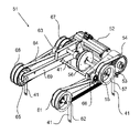
도 6은 봇(31)의 컨테이너 리프팅 메커니즘(39)을 위한 승강 어셈블리(51)를 도시한다. 승강 어셈블리(51)는 모터(52)의 출력을 회전시키도록 구성된 단일 모터(52)를 포함한다. 모터(52)는 단일 모터를 포함하고, 이하의 설명에서 "모터" 및 "단일 모터"라는 용어는 상호 교환 가능하게 사용된다. 모터의 출력은 예를 들어 모터(52)의 본체로부터 연장되고 예를 들어, 모터(52)의 종축을 중심으로, 모터(52)의 다른 컴포넌트에 의해 회전 가능한 샤프트(shaft) 또는 스핀들(spindle)일 수 있다.6 shows the lifting
제 1 타이밍 풀리(timing pulley)(53)는 모터(52)의 출력에 연결되어, 모터(52)의 출력이 회전되면 제 1 타이밍 풀리(53)가 회전된다. 제 1 타이밍 풀리(53)는 예를 들어 모터(52)의 출력에 고정 장착될 수 있다.The
모터(52)에 의한 제 1 타이밍 풀리(53)의 회전은 제 1 타이밍 풀리(53) 및 제 2 타이밍 풀리(55) 주위에서 인장되는 제 1 타이밍 벨트(54)의 대응하는 회전을 야기한다. Rotation of the
제 1 타이밍 벨트(54)의 회전은 차례로 제 2 타이밍 풀리(55)가 장착된 샤프트(56) 상에서 제 2 타이밍 풀리(55)을 회전시킨다. 샤프트(56)는 제 2 타이밍 풀리(55)와 함께 회전된다.Rotation of the
테이프(41)의 제 1 스풀(spool)(57)도 샤프트(56)에 장착된다. 제 1 스풀(57)은 샤프트(56)와 함께 회전되어, 샤프트(56) 및 스풀(57)의 회전 방향에 따라, 테이프(41)가 제 1 스풀(57)로부터 풀리거나 제 1 스풀(57)에 감기도록 하여, 테이프(41)의 말단부를 상승 또는 하강시킨다.A
도 6에 도시된 바와 같이, 테이프(41)의 말단부는 테이프(41)를 컨테이너 그리핑 어셈블리[도 4 및 도 5에 도시된 컨테이너 그리핑 어셈블리(43)와 같은]에 연결하기 위한 수단을 포함한다. 도시된 수단은 테이프(41)의 단부 상의 탭(tab)을 포함하고, 상기 탭은 컨테이너 그리핑 어셈블리의 대응하는 특징부가 삽입될 수 있는 구멍을 포함한다. 다른 형태에서, 테이프(41)는 테이프(41)를 컨테이너 그리핑 어셈블리에 연결하기 위한 다른 또는 상이한 수단, 예를 들어 하나 이상의 구멍, 후크 또는 컨테이너 그리핑 어셈블리 상의 대응하는 체결 특징부(fastening features)와 결합될 수 있는 다른 체결 특징부를 포함할 수 있다. 대안적으로, 테이프(41)의 말단부들은 컨테이너(9)에 직접 연결되거나(즉, 개재된 컨테이너 그리핑 어셈블리 없이), 또는 (컨테이너 그리핑 어셈블리 또는 다른 방법을 통해) 컨테이너(9)에 연결되는 추가 컴포넌트에 연결되도록 구성될 수 있다. 이러한 형태에서, 테이프들(41)의 단부들에서의 특징부는 컨테이너 그리핑 어셈블리로 간주될 수 있다.As shown in FIG. 6 , the distal end of the
제 3 타이밍 풀리(59)도 샤프트(56)에 장착된다. 제 3 타이밍 풀리(59)는 샤프트(56)와 함께 회전되어, 제 3 타이밍 풀리(59) 및 제 4 타이밍 풀리(61) 주위에 인장된 제 2 타이밍 벨트(60)를 회전시킨다. 제 4 타이밍 풀리(61)는 제 4 타이밍 풀리(61)와 함께 회전되는 샤프트에 장착되며, 또한 제 4 타이밍 풀리(61)와 동일한 샤프트에 장착된 테이프(41)의 제 2 스풀(62)을 회전시킨다.A
유사하게, 제 5 타이밍 풀리(63) 및 테이프(41)의 제 3 스풀(67)은 제 2 타이밍 풀리(55), 테이프(41)의 제 1 스풀(57) 및 제 3 타이밍 풀리(59)로부터 샤프트(56)의 대향 단부에서, 샤프트(56)에 장착되어 샤프트(56)와 함께 회전된다. 제 5 타이밍 풀리(63)가 샤프트(56)와 함께 회전됨에 따라, 제 5 타이밍 풀리(63) 및 제 6 타이밍 풀리(65)를 중심으로 장력을 받는 제 3 타이밍 벨트(64)가 회전하게 된다. 제 6 타이밍 풀리(65)는 제 6 타이밍 풀리(65)와 함께 회전되며 또한 제 6 타이밍 풀리(65)와 동일한 샤프트에 장착된 테이프(41)의 제 4 스풀(68)의 회전을 일으키는 샤프트에 장착된다.Similarly, the
도시된 실시 형태에서, 제 2, 제 3 및 제 4 스풀들(62, 67, 68)은 제 1 스풀(57)과 실질적으로 동일하고, 회전 방향에 따라, 회전될 때 스풀들(62, 67, 68)로부터 테이프(41)를 감거나 풀기 위해 실질적으로 동일한 방식으로 작동된다.In the embodiment shown, the second, third and
도시된 실시 형태에서, 타이밍 풀리들(53, 55, 59, 61, 63, 65)은 서로 실질적으로 동일하다. 타이밍 풀리들(53, 55, 59, 61, 63, 65) 및 그 각각의 타이밍 벨트들(54, 60, 64)은 톱니 및 대응하는 그루브(grooves) 또는 리세스(recesses)를 통해 결합된다. 다른 실시 형태에서, 타이밍 풀리는, 원하는 경우, 예를 들어 속도 차별화 또는 기타 기능을 제공하기 위하여, 다른 것과는 상이하게 크기가 정해질 수 있다. 유사하게, 타이밍 풀리와 그 각각의 타이밍 벨트에는 요구 사항에 따라, 서로 결합하도록 상이한 특징부가 제공될 수 있다. 타이밍 벨트는 요구 사항에 따라, 다른 커넥터, 예를 들어 타이밍 체인으로 대체할 수도 있다.In the embodiment shown, the timing pulleys 53 , 55 , 59 , 61 , 63 , 65 are substantially identical to each other. Timing pulleys 53 , 55 , 59 , 61 , 63 , 65 and their
도시된 실시 형태에서, 텐셔너들(tensioners)은 타이밍 벨트(60, 64)의 장력을 유지 및/또는 조정하는 것을 돕기 위해 제공된다[예를 들어, 텐셔너(66) 참조]. 원하는 경우, 예를 들어 타이밍 벨트(54)의 장력을 유지 또는 조정하는 것을 돕기 위해, 추가 텐셔너가 제공될 수 있다. 도시된 텐셔너들은 풀리들(59, 61, 63, 65)의 회전축 아래에 제공된다. 다른 형태에서, 예를 들어, 승강 어셈블리(51) 아래에 더 많은 공간이 필요한 경우, 즉 텐셔너가 아래 공간에 충돌하지 않도록 해야 하는 경우, 텐셔너는 축 위에 위치될 수 있다. In the illustrated embodiment, tensioners are provided to help maintain and/or adjust the tension of the
승강 어셈블리(51)의 컴포넌트는 승강 어셈블리(51)의 프레임 구조체(69)에 지지된다. 프레임 구조체(69)는 다양한 컴포넌트들이 프레임 구조체(69) 상에 직접 또는 간접적으로 장착될 수 있게 하고, 승강 어셈블리(51)를 위한 비교적 견고한 전체 구조체를 제공하기 위해 적합한 구멍, 그루브, 슬롯(slots), 크로스 부재(cross members) 및 기타 특징부를 포함한다. 프레임 구조체(69)는 봇(31)의 본체(33)와 해제 가능하게 결합될 수 있도록 구성될 수 있다. 그것은 예를 들어 봇(31)의 본체(33)의 내부 및 외부로 슬라이딩되도록 배치될 수 있고, 프레임 구조체(69) 및 봇(31)의 본체(33)[또는 봇(31)의 본체(33)에 장착된 하나 이상의 컴포넌트]에 대응하는 구멍, 그루브 또는 슬롯과 결합되는 너트 및 볼트와 같은 적합한 고정 수단으로 본체(33)에 대해 제자리에 유지될 수 있다. 프레임 구조체(69) 및 봇(31)의 본체(33)(또는 봇(31)의 본체(33)에 장착된 하나 이상의 컴포넌트). 본체(33)와 해제 가능한 결합을 위한 승강 어셈블리(51)를 구성하는 것은, 유리하게는 승강 어셈블리(51)가 쉽게 제거될 수 있고 다른 어셈블리(51)[예를 들어, 제 1 어셈블리(51)를 수리하거나 수리해야 하는 경우]로 교체될 수 있어, 대응하는 봇(31)이 비교적 신속하게 서비스로 복귀될 수 있게 한다는 것을 의미할 수 있다.The components of the
도시된 배치는 단일 모터(52)가 4개의 모든 스풀들(57, 62, 67, 68)로부터 테이프(41)를 상승 및 하강시키는 것을 가능하게 한다. 도시된 장치는, 봇(31)의 본체(33) 내의 비용 및 공간이 더 많은 모터를 통합하는 장치에 비해 절약될 수 있고; 4개의 다른 스풀들(57, 62, 67, 68)의 감기 및 풀기 속도는, 모두 동일한 모터로 구동되므로, 동기화할 필요가 없으며, 추가적인 기어링(gearing), 제어 또는 다른 개입 없이 동일한 속도로 감기거나 풀릴 수 있도록 하고; 모터를 감속 또는 정지하기 위해 단 하나의 브레이크만 필요하며 따라서 다른 스풀들(57, 62, 67, 68)의 감기 및 풀림이 필요하고; 4개의 다른 스풀들(57, 62, 67, 68)의 상승 및 하강을 제어하는 데 단일 제어 유닛만 필요한데, 이는 단일 제어 유닛이 단일 모터를 제어하여 이러한 상승 및 하강 제어를 달성할 수 있기 때문이며; 프레임 구조체(69) 내에[즉, 제 3, 제 4, 제 5 및 제 6 타이밍 풀리들(59, 61, 63, 65) 사이에] 큰 개방 개구가 형성되어 다른 컴포넌트가 봇(31)의 본체(33) 내에 수용될 수 있게 하고 및/또는 승강 어셈블리(51)가 제자리에 있을 때 컴포넌트가 봇(31)의 본체(33) 내로 보다 쉽게 삽입되고 본체(33)로부터 제거될 수 있도록 하는, 이점을 포함하는 다양한 이점을 갖는다. 이것은 특히 유리하게는 봇(31)의 본체(33) 내의 컴포넌트가 더 자주 교체되도록 할 수 있고; 예를 들어, 봇(31)의 충전식 배터리를 봇(31)의 본체(33)로부터 쉽게 제거할 수 있고 다른 충전식 배터리로 교체할 수 있다. 도시된 단일 모터(52)가 샤프트(56)의 외부[즉, 테이프(41)의 스풀들(57, 62, 67, 68)의 모든 회전축의 외부]에 장착된다는 사실은 이러한 이점들 중 하나 이상, 특히 프레임 구조체(69) 내에서 큰 개방 개구를 형성하는 것과 관련된 이점들을 제공하는 데 도움을 줄 수 있다. 단일 모터(52)의 외부 장착은 봇(31)의 질량 중심의 균형을 맞추는 데, 예를 들면 프레임 구조체(69)의 질량과 승강 어셈블리(51)의 다른 컴포넌트의 균형을 맞추는 데 더 도움을 줄 수 있다.The arrangement shown allows a
다수의 스풀들(57, 62, 67, 68)의 상승 및 하강을 제어하도록 구성된 단일 모터는 또한 유리한 기어링 장치의 사용을 허용할 수 있다. 그러한 기어 장치를 갖는 단일 모터를 사용하는 것은, 유리하게는 모터 관성과 들어 올려질 컨테이너(9)의 부하 관성을 더 잘 일치시키는 것을 도울 수 있다. 예를 들어, 단일 모터를 사용하는 것은 다수의 모터 및 다수의 대응하는 기어링 장치를 사용하는 것보다 유리한 기어링 메커니즘을 위한 더 많은 공간을 허용할 수 있으며, 특히 도시된 단일 모터 구성 및 다수의 모터 구성에서 기어링 장치의 대응하는 크기를 허용할 수 있다. 도시된 형태에서, 단일 모터(52)의 출력은 기어링 메커니즘을 통해 제 1 타이밍 풀리(53)에 연결된다.A single motor configured to control the raising and lowering of
유리한 기어링 장치를 갖는 단일 모터는 또한 예를 들어 모터 회전수와 테이프(41)의 말단부의 대응하는 직선 이동 사이의 더 큰 비율을 허용하고, 승강 어셈블리(51)를 사용하여 승강되는 컨테이너(9) 또는 기타 부하에 의해 이동되는 거리를 더 정밀하게 제어함으로써, 부하(load)의 상승 및 하강을 보다 정밀하게 제어할 수 있다. 이것은 컨테이너(9)가 너무 멀리 상승되거나 하강되지 않도록 보장함으로써, 컨테이너(9), 봇(31)의 본체(33) 및/또는 봇(31) 부근의 다른 물체에 대한 손상을 최소화하는 데 도움을 줄 수 있다. 또한 위치 및 관성과 관련하여 기어박스(gearbox)의 이점으로 인해 더 나은 동적 서보 시스템(servo system)을 허용할 수 있다. 단일 모터로 스풀들(57, 62, 67, 68)의 감기 및 풀기를 제어하는 데 필요한 센서들 및 인코더들(encoders)의 수를 줄일 수 있는데, 그 이유는 단 하나의 모터의 회전만 모니터링되고 제어될 필요가 있고, 하드 스톱(hard stops)의 필요성을 제거할 수 있기 때문이다.A single motor with advantageous gearing arrangement also allows for a greater ratio between the number of motor revolutions and the corresponding linear movement of the distal end of the
유리하게는, 4개의 상이한 스풀들(57, 62, 67, 68)의 감기 및 풀림을 제어하기 위해 단일 모터를 갖는 도시된 승강 어셈블리(51)는, 또한 제어 유닛과 승강 어셈블리(51)를 연결하는 데 필요한 전기 케이블의 수 및/또는 체적을 최소화할 수 있는데, 그 이유는 상이한 케이블이 다수의 모터 각각으로 지향될 필요가 없기 때문이다. 이것은 또한 승강 어셈블리(51)를 삽입 및 제거하고, 승강 어셈블리(51)를 통해 또는 그 주위에서 봇(31)의 다른 컴포넌트를 제거하는 것을 더 용이하게 할 수 있는데, 이는 승강 어셈블리(51)를 제어 유닛으로부터 분리하기 위해, 단일 케이블(또는 단일 세트의 케이블)만을 분리할 필요가 있기 때문이다.Advantageously, the illustrated lifting
도시된 실시 형태에서, 통신 케이블 릴(cable reel)은 또한 제 3 타이밍 풀리(59)와 제 5 타이밍 풀리(63) 사이의 샤프트(56)에 장착된다. 통신 케이블은 제어 유닛으로부터 테이프(41)의 단부에 있는 그리핑 수단(gripping means)으로 제어 명령을 전송한다. 유리하게는, 도시된 실시 형태에서, 통신 케이블 릴이 샤프트(56) 상에 장착되고 샤프트와 함께 회전됨에 따라, 통신 케이블은 또한 단일 모터(52)의 작용에 의해 상승 및 하강된다. 이는 통신 케이블의 말단부가 테이프(41)의 말단부와 동일한 속도로 상승 및 하강되며, 따라서 통신 케이블이 컨테이너 그리핑 어셈블리(43)에 의해 하강 및 후퇴하는 것을 보장하기 위해 더 이상의 동기화가 필요하지 않다는 것을 의미한다. 단일 모터(52)의 외부 장착은 샤프트(56) 상의 통신 케이블 릴의 이러한 장착을 가능하게 할 수 있다.In the illustrated embodiment, a communication cable reel is also mounted on the
단일 모터(52)가 컨테이너 그리핑 어셈블리(43) 및 임의의 결합된 컨테이너(9)를 상승 또는 하강시키기 전에, 휠-포지셔닝 메커니즘(wheel-positioning mechanism)은 바람직하게는 봇(31)의 제 1 세트의 휠(35) 및 제 2 세트의 휠(37) 모두가 제 1 및 제 2 세트의 트랙(17, 19)에서, 각각의 트랙(17, 19)과 결합되는 것을 보장한다. 이것은 유리하게는 컨테이너 그리핑 어셈블리(43)가 상승 및 하강될 때 추가적인 안정성을 제공할 수 있고, 봇(31)이 트랙(17, 19)을 따라 이동하게 하는 휠들(35, 37) 중 하나 이상의 오작동이 트랙과 접촉하는 다른 세트의 휠에 의해 상쇄되도록 보장하는데 추가적으로 도움을 줄 수 있다. 이는 컨테이너 그리핑 어셈블리(43)가 하강된 구성에 있는 동안 봇(31)이 이동하려고 시도하는 경우 보관 구조체(1)에 대한 손상을 유리하게 방지할 수 있다.Before the
도시된 실시 형태에서 회전은 타이밍 벨트들(54, 60, 64)을 사용하여 다양한 엔티티들 사이에서 전달되지만, 다른 실시 형태에서는, 하나 이상의 타이밍 벨트 대신에 하나 이상의 기어가 사용될 수 있다. 이러한 경우, 기어의 수는 회전 방향이 적합하게 전달되는 것을 보장하기 위해 선택될 수 있다. 대안적으로, 모터(52)의 출력은 예를 들어, 타이밍 풀리들(53, 55) 사이에 홀수의 기어들의 존재를 수용하도록 역전될 수 있다. 도 6을 참조하여 본 발명의 특정 실시 형태의 설명의 용이함을 위해, 스풀(57)은 제 1 스풀(57)에 의해 형성되고, 스풀(62)은 제 2 스풀(62)에 의해 형성되며, 스풀(67)은 제 3 스풀(67)에 의해 형성되고, 스풀(68)은 제 4 스풀(68)에 의해 형성된다. 제 1 스풀(57) 및 제 3 스풀(67)은 샤프트(56)에 장착된다. 제 2 스풀(62)과 제 4 스풀(68)은 별도의 샤프트에 장착된다. 제 1 스풀(57)과 제 3 스풀(67)은 제 1 세트의 스풀(57, 67)을 제공하고, 제 2 스풀(62)과 제 4 스풀(68)은 제 2 세트의 스풀(62, 68)을 제공한다. 도 6에 도시된 본 발명의 특정 실시 형태에서, 제 1 및 제 2 세트의 스풀들의 각각은 단일 모터(52)에 의해 구동되는 별도의 샤프트에 장착되어 복수의 타이밍 풀리들 및/또는 타이밍 벨트들(54, 60, 64) 및/또는 기어들을 통해 컨테이너 그리핑 어셈블리(43)를 상승 및 하강시킨다.In the illustrated embodiment rotation is transmitted between the various entities using
도 6을 참조하여 본 발명의 특정 실시 형태를 용이하게 설명하기 위해, 타이밍 풀리(53)는 제 1 타이밍 풀리(53)에 의해 형성되고, 타이밍 풀리(55)는 제 2 타이밍 풀리(55)에 의해 형성되고, 타이밍 풀리(59)는 제 3에 의해 형성되고, 타이밍 풀리(61)는 제 4 타이밍 풀리(61)에 의해 형성되고, 타이밍 풀리(63)는 제 5 타이밍 풀리(63)에 의해 형성되고, 타이밍 풀리(65)는 제 6 타이밍 풀리(65)에 의해 형성된다. 제 3 타이밍 풀리(59) 및 제 5 타이밍 풀리(63)는 샤프트(56)에 장착된다. 제 3 타이밍 풀리(59) 및 제 5 타이밍 풀리(63)는 제 1 세트의 타이밍 풀리(59, 63)를 제공한다. 제 4 타이밍 풀리(61) 및 제 6 타이밍 풀리(65)는 별도의 샤프트에 장착된다. 제 4 타이밍 풀리(61) 및 제 6 타이밍 풀리(65)는 제 2 세트의 타이밍 풀리(61, 65)를 제공한다. 제 1 타이밍 풀리(53)는 예를 들어, 드라이브 로터(drive rotor) 상에서 단일 모터(52)의 출력에 장착된다. 제 2 타이밍 풀리(55)는 구동 풀리(drive pulley)를 제공한다. 제 2 타이밍 풀리 또는 구동 풀리(55)는 제 1 세트의 타이밍 풀리들(59, 63)을 장착하는 샤프트(56)에 장착되고 타이밍 벨트/체인(54)에 의해 구동 로터에 장착된 제 1 타이밍 풀리(53)에 연결되어, 단일 모터(52)에 의해 구동되는 제 1 타이밍 풀리(53)의 회전은 샤프트에 장착된 제 2 타이밍 풀리 또는 구동 풀리(55)의 회전을 구동하며, 따라서 샤프트(56)에 장착된 제 1 세트의 타이밍 풀리들(59, 63)의 회전을 구동한다. 이것은 차례로 샤프트(56)에 장착된 제 1 세트의 스풀들(57, 67)을 회전시키도록 한다.To facilitate describing a specific embodiment of the present invention with reference to FIG. 6 , the timing
도 6a는 봇(31)의 컨테이너 리프팅 메커니즘(39)을 위한 승강 어셈블리(51)의 제 2 형태를 도시한다. 승강 어셈블리(51)는 모터(52)의 출력을 회전시키도록 구성된 단일 모터(52)를 포함한다. 모터(52)는 단일 모터를 포함하고, 이하의 설명에서 "모터" 및 "단일 모터"라는 용어는 상호 교환 가능하게 사용된다. 모터의 출력은 예를 들어 모터(52)의 본체로부터 연장되고 모터(52)의 다른 컴포넌트에 의해, 예를 들어, 모터(52)의 종축을 중심으로 회전 가능한 로터 샤프트(rotor shaft) 또는 스핀들(spindle)일 수 있다.6a shows a second form of the lifting
도 6a에 대한 이 설명에서, 상기 도 6에 대한 설명과 동일한 참조 번호가 사용될 것이다. 도 6 및 도 6a의 특정 실시 형태는 상이한 수의 타이밍 풀리 및 타이밍 벨트를 포함하기 때문에, 타이밍 풀리 및 타이밍 벨트는 서수(제 1, 제 2, 제 3 등)보다는 참조 번호로 지칭될 것이다. 도 6a에서, 타이밍 풀리(55)는 구동 풀리이며, 이는 또한 제 1 세트의 타이밍 풀리들 중 하나이다. 도 6에서와 같이, 제 1 세트의 풀리들(55, 63)은 샤프트(54)에 장착되고, 제 2 세트의 타이밍 풀리들(61, 65)은 별도의 샤프트에 장착된다.In this description of FIG. 6A, the same reference numerals as those in the description of FIG. 6 will be used. Because the particular embodiments of FIGS. 6 and 6A include different numbers of timing pulleys and timing belts, the timing pulleys and timing belts will be referred to by reference numbers rather than ordinal numbers (first, second, third, etc.). 6A, timing
타이밍 풀리(53)는 모터(52)의 출력에 연결되어, 모터(52)의 출력의 회전이 타이밍 풀리(53)의 회전을 야기한다. 타이밍 풀리(53)는 예를 들어 모터(52)의 출력, 예를 들어 로터 샤프트에 고정 장착될 수 있다.The timing
모터(52)에 의한 타이밍 풀리(53)의 회전은 3개의 타이밍 풀리들, 즉 타이밍 풀리(53), 구동 풀리(55), 및 타이밍 풀리(61)(제 2 세트의 타이밍 풀리들 중 하나) 주위에 인장된 타이밍 벨트(54)의 대응하는 회전을 야기한다. 타이밍 벨트(54)의 회전은 차례로 구동 풀리(55)가 장착된 샤프트(56) 상에서 구동 풀리(55)의 회전을 야기한다. 샤프트(56)는 구동 풀리(55)와 함께 회전된다. 제 2 세트의 타이밍 풀리들 중 하나인 타이밍 풀리(61)는, 타이밍 풀리(61)와 함께 회전되는 별도의 샤프트에 장착된다.Rotation of timing
테이프(41)의 제 1 스풀(57)은 또한 샤프트(56)에 장착된다. 제 1 스풀(57)은 샤프트(56)와 함께 회전되어, 샤프트(56) 및 스풀(57)의 회전 방향에 따라, 테이프(41)가 제 1 스풀(57)로부터 풀리거나 제 1 스풀(57)에 감기도록 하며, 따라서 테이프(41)의 말단부를 상승 또는 하강시킨다. 테이프(41)의 말단부는 컨테이너 그리퍼 어셈블리에 고정된다. 타이밍 풀리(61)(제 2 세트의 타이밍 풀리들 중 하나임)는 제 3 타이밍 풀리(61)와 동일한 샤프트에 장착되는 테이프(41)의 제 2 스풀(62)의 회전을 야기한다.A
유사하게, 타이밍 풀리(63)(제 1 세트의 타이밍 풀리들 중 하나임) 및 테이프(41)의 제 3 스풀(67)은, 구동 풀리(55) 및 테이프(41)의 제 1 스풀(57)로부터 샤프트(56)의 대향 단부에서, 샤프트(56)에 장착되어 샤프트(56)와 함께 회전된다. 타이밍 풀리(63)가 샤프트(56)와 함께 회전됨에 따라, 타이밍 풀리(63)와 타이밍 풀리(65) 주위에 인장된 타이밍 벨트(64)의 회전을 야기한다. 타이밍 풀리(65)(제 2 세트의 타이밍 풀리들 중 하나임)는 타이밍 풀리(65)와 함께 회전되는 별도의 샤프트에 장착되며 또한 타이밍 풀리(65)와 동일한 샤프트 상에 장착되는 테이프(41)의 제 4 스풀(68)의 회전을 야기한다. 따라서, 타이밍 벨트/체인(54)에 의한 구동 풀리(55) 및 제 3 타이밍 풀리(61)와 타이밍 풀리(53)의 연결 및 타이밍 벨트/체인(64)에 의한 타이밍 풀리(63)와 타이밍 풀리(65)의 연결은, 단일 모터가 구동될 때 제 1 및 제 2 세트의 스풀들(57, 62, 67, 68)의 동기화된 회전 운동을 제공한다.Similarly, the timing pulley 63 (which is one of the first set of timing pulleys) and the
도시된 실시 형태에서, 텐셔너들은 타이밍 벨트(54, 64)의 장력을 유지 및/또는 조정하는 것을 돕기 위해 제공된다[예를 들어, 텐셔너(66) 참조]. 도시된 텐셔너들은 제 1 세트의 타이밍 풀리들(55, 63) 및 제 2 세트의 타이밍 풀리들(61, 65)의 회전축 위에 제공되고 타이밍 벨트들(54, 64)은 텐셔너들 아래를 통과한다. 텐셔너(66)를 예로 들면, 텐셔너(66)의 위치 결정은 타이밍 벨트(54)와 구동 풀리(55) 사이의 접촉 면적을 증가시키는 이점을 갖는다. 도 6의 실시 형태와 달리, 타이밍 벨트(54)는 3개의 풀리들(53, 55, 61) 주위에서 인장된다. 텐셔너가 없으면, 중앙 구동 풀리(55)와 타이밍 벨트(64) 사이의 접촉 면적이 작을 것이고, 이는 타이밍 벨트(64)가 미끄러질 위험을 증가시킬 것이다.In the illustrated embodiment, tensioners are provided to help maintain and/or adjust the tension of the
도 6을 참조하여 전술한 실시 형태와 유사한 장치에서, 제 1 및 제 3 스풀(57, 67)을 포함하는 제 1 세트의 스풀들은 샤프트(56)에 장착된다. 제 2 및 제 4 스풀(62, 68)을 포함하는 제 2 세트의 스풀들은 별도의 샤프트에 장착된 것으로 도시되어 있다. 별도의 샤프트에 장착된 제 1 및 제 2 세트의 스풀들의 각각은 단일 모터에 의해 구동되어 복수의 타이밍 풀리들 및/또는 타이밍 벨트들(54, 60, 64) 및/또는 기어들을 통해 컨테이너 그리퍼 어셈블리를 상승 및 하강시킨다.In a device similar to the embodiment described above with reference to FIG. 6 , a first set of spools comprising first and
도 6a의 실시 형태에서, 2개의 타이밍 벨트(54, 60)가 동일한 목적을 위해 사용되는 도 6의 실시 형태와 달리, 2개의 스풀들(57, 62)의 회전을 구동하기 위해 3개의 타이밍 풀리들(53, 55, 61) 주위에 단일 타이밍 벨트(54)를 사용하는 것은 더 작은 부품 수의 이점을 갖는다. 이것은 승강 어셈블리(51)의 비용, 중량 및 복잡성을 감소시킨다. 도 6a의 실시 형태의 구동 풀리(55)는 도 6의 실시 형태의 2개의 타이밍 풀리[구동 풀리(55) 및 제 3 타이밍 풀리(59)]의 기능을 수행하는 단일 타이밍 풀리이다. 따라서, 도 6의 실시 형태와 비교하여, 도 6a의 실시 형태에서는 하나의 타이밍 벨트와 하나의 타이밍 풀리가 제거된다.In the embodiment of FIG. 6A , in contrast to the embodiment of FIG. 6 , where two
승강 어셈블리(51)의 컴포넌트는 승강 어셈블리(51)의 프레임 구조체(69)에 지지된다. 도 6a의 실시 형태에서, 2개의 타이밍 벨트(54, 64)는 프레임 구조체(69)의 외부에 위치된다. 타이밍 풀리(59)의 제거는 부품 수의 감소가 패키징(packaging)에 유리하기 때문에, 타이밍 벨트가 프레임 구조체의 외부에 위치될 수 있게 한다. 프레임 구조체(69)의 외부에 타이밍 벨트(54, 64)를 위치시키는 것의 이점은 타이밍 벨트(54, 64)가 유지보수(예를 들어, 텐셔너 조정) 또는 교체를 위해 더 쉽게 접근할 수 있다는 것이다.The components of the
4개의 스풀들(57, 62, 67, 68)은 각각의 타이밍 풀리(55, 61, 63, 65)에 연결될 수 있어, 타이밍 벨트(54, 64)는 타이밍 풀리와 스풀이 함께 또는 동기화되어 회전되도록 한다. 각 스풀은 각각의 타이밍 풀리에 볼트로 고정되거나, 다른 수단으로 부착될 수 있다. 여기서 연결은 제 1 스풀(57) 및 구동 풀리(55)와 관련하여 설명되지만, 4개의 스풀들(57, 62, 67, 68)의 각각과 그 각각의 타이밍 풀리(55, 61, 63, 65) 사이의 연결은 실질적으로 동일할 수 있는 것이 이해될 것이다.The four
도 6b 및 도 6c는 타이밍 풀리(55)에 볼트로 고정된 스풀(57)의 2개의 도면을 도시한다. 스풀(57)은 하나 이상의 볼트(58)로 타이밍 풀리(55)에 연결된다. 볼트(58)는 스풀(57)과 타이밍 풀리(55) 사이의 조정 가능한 연결을 제공한다. 볼트는 스풀(57)과 타이밍 풀리(55) 사이의 조정 메커니즘의 일 형태이지만, 다른 형태의 조정 메커니즘이 당업자에게 알려져 있음이 이해될 것이다.6b and 6c show two views of the
스풀(57)에는 볼트(58)가 통과될 수 있는 하나 이상의 슬롯(slots)이 제공될 수 있다. 슬롯은 스풀(57)과 타이밍 풀리(55) 사이의 각도 조정을 허용한다. 컨테이너 그리퍼 어셈블리는 사용 시 수평을 유지할 필요가 있으므로, 스풀의 각도 위치를 미세 조정할 수 있는 기능이 바람직하다. 예를 들어 테이프들(41) 중 하나가 늘어나거나 꼬이게 되면, 테이프(41)의 길이가 더 이상 동일하지 않도록, 스풀의 각도 위치를 조정하는 것이 필요할 수 있다.
조정 메커니즘을 통해 스풀(57)을 타이밍 풀리(55)에 연결하는 것은, 조정 메커니즘이 스풀의 각도 위치를 결정하는 공차 스택 업(stack-up)의 일부를 대체한다는 추가적인 이점을 갖는다. 더 작은 공차 스택 업은 승강 어셈블리(51)의 부품에 대한 공차가 덜 정확할 수 있다는 것을 의미하고, 이는 제조 공정들에 대한 비용을 절감한다. 예를 들어, 부품은 부품의 정밀 기계 가공보다는 용접 가공에 의해 제조될 수 있다.Connecting the
대안적으로, 스풀(57)과 타이밍 풀리(55)는 일체형 부품으로 제조될 수 있다. 이것은 승강 어셈블리(51)의 부품 수 및 복잡성을 추가로 감소시키는 이점을 갖는다.Alternatively, the
타이밍 풀리(55)와 스풀(57)은 승강 어셈블리(51)의 프레임 구조체(69)에 장착된다.The timing
도 7 및 도 8은 컨테이너(9)를 상승 및 하강시키기 위한 로드-핸들링 디바이스(31)를 위한 대안적인 승강 어셈블리들(리프팅 어셈블리라고도 함)(70, 80)의 형태를 도시한다. 리프팅 어셈블리들(70, 80) 각각은 각각의 출력이 타이밍 벨트(54)를 통해 타이밍 풀리 또는 기어(55, 72)에 연결되는 모터(52)를 포함한다.7 and 8 show the form of alternative lifting assemblies (also called lifting assemblies) 70 , 80 for the rod-handling
기어(55)를 통해 연장되는 공통 샤프트 또는 액슬(axle)(56)은 제 1 및 제 2 테이프 스풀들 또는 호이스트 드럼들(71, 75)로 연장되며, 그 둘레에 리프팅 테이프(41)가 감겨진다. 리프팅 테이프(41)의 제 1 단부는 호이스트 드럼(71, 75)에 부착된다. 테이프(41)의 제 2 말단부는 전술한 바와 같이 컨테이너 그리핑 어셈블리(43)(그리퍼 플레이트라고도 함)에 연결될 수 있거나, 그렇지 않으면 컨테이너 그리핑 어셈블리가 상승 또는 하강할 수 있도록 컨테이너 그리핑 어셈블리를 지지할 수 있다. 슬레이브 휠(Slave wheels)(73)은 리프팅 테이프(41)를 리프팅 테이프(41)의 단부에 부착된 그리퍼 플레이트로 안내하고 및/또는 도 6과 관련하여 위에서 설명된 텐셔너(66)와 같이, 리프팅 테이프(41)의 장력을 조정하는 데 사용된다. 그리퍼 플레이트는 하중에 래치(latch)하기 위해 사용되며, 하중은 리프팅 어셈블리(70, 80)에 의해 상승되거나 하강될 수 있다.A common shaft or
도 7에 도시된 어셈블리(70)의 경우, 두 개의 리프팅 테이프들(41)이 두 개의 드럼들(71) 각각에 교대로 감겨져 있다. 따라서, 제 1, 제 2 드럼(71)이 모터(52)에 의해 회전되어 그리퍼 플레이트를 하강시키면, 4개의 테이프들(41) 모두가 동시에 동일한 속도로 풀리게 된다. 반대로, 리프팅 테이프(41)는 호이스트 드럼(71) 주위를 동일한 시간 및 속도로 감싸거나 감아서, 그리퍼 플레이트에 의해 지지되는 중량 또는 페이로드(payload)를 상승시킨다.In the case of the
도 8에 도시된 어셈블리(80)의 경우, 리프팅 테이프(41)의 제 1 및 제 2 단부는 액슬 또는 샤프트(56)의 각 단부에서 트윈 드럼(75) 둘레에 감겨 있다.For the
두 어셈블리(70, 80)의 경우, 액슬(56)의 각 단부에서, 테이프(41)는 어셈블리에 가해지는 힘의 균형을 맞추기 위해, 각각 드럼(71, 75)의 상부 및 하부로부터 풀린다. 두 어셈블리(70, 80)의 경우 드럼(71, 75)은 z,x-평면에 있다. 대안적으로, 드럼(71, 75)은 z,y-평면에 배치될 수 있다.For both
드럼(71)의 직경은 주어진 길이의 리프팅 테이프(41)에 대해 각각의 드럼(75)의 직경보다 반드시 더 크다는 것이 이해될 것이다. 이에 대응하여, 기어(55)는 기어(72)보다 크고, 도 7의 모터(52)에 의해 생성된 요구 토크는 도 8의 모터(52)에 의해 생성된 요구 토크보다 크다.It will be appreciated that the diameter of the
리프팅 어셈블리(70)는 더 적은 부품이 필요하다는 이점을 갖는다. 리프팅 어셈블리(80)는 도 8의 드럼(75), 기어(72) 및 모터(52)가 더 작게 제조될 수 있다는 이점을 갖는다. 두 경우 모두, 리프팅 어셈블리(70, 80)에 의해 로드-핸들링 디바이스(31)의 본체 내에 요구되는 공간이 최소화될 수 있다.The lifting
4개의 테이프가 사용되는 경우 그리퍼 플레이트가 리프팅 테이프(41)의 말단부에 부착될 수 있는 것이 이해될 것이다. 다른 실시 형태에서 대안적인 장치가 사용될 수 있다는 것이 이해될 것이다. 예를 들어, 일부 실시 형태에서, 2개의 테이프들(41)만이 사용되는 슬링 장치(sling arrangement)가 제공될 수 있으며, 테이프들(41)은 그리퍼 플레이트에 장착된 풀리 사이를 통과하고(예: 도 12에 도시된 풀리의 장치와 유사한 방식으로), 그리퍼 플레이트는 풀리를 통과하는 테이프(41)의 슬링에 의해 지지된다. 그리퍼 플레이트는 보관 컨테이너(9)에 래칭(latching)하기 위해 그 위에 장착된 하나 이상의 그리퍼 어셈블리를 가질 것이다.It will be appreciated that a gripper plate may be attached to the distal end of the lifting
도 7 및 도 8에 도시된 하나 이상의 컴포넌트는 도 6에 도시된 프레임(69)과 같은 프레임에 장착될 수 있다. 이것은 유리하게 대안적인 리프팅 어셈블리들(70, 80)이 로드-핸들링 디바이스(31)의 본체 내부에 제거 가능하게 장착되고 고장이 발생된 경우 교체 리프팅 어셈블리로 쉽게 교체될 수 있게 한다.One or more components shown in FIGS. 7 and 8 may be mounted to a frame, such as
도 9 및 도 10은 리프팅 어셈블리들(90, 100)를 위한 대안적인 드럼 장치들을 도시한다. 두 어셈블리들(90, 100)의 경우 호이스트 드럼(221, 231)은 x,y-평면에 있다. 이러한 배치는 드럼이 로드-핸들링 디바이스(31)의 본체 내에서 훨씬 더 많은 공간을 차지하지 않으면서 훨씬 더 커질 수 있다는 이점을 갖는다. 대신에, 드럼(221, 231)은 로드-핸들링 디바이스의 상부면 또는 표면과 실질적으로 평면상에 있다. 드럼(221, 231)의 직경은 실질적으로 로드-핸들링 디바이스의 더 짧은 x- 또는 y-측의 길이까지일 수 있다.9 and 10 show alternative drum arrangements for the
유리하게는 드럼(221, 231)은 훨씬 더 작은 모터(222, 232)로 감긴다. 모터(222)의 구동 샤프트는 드럼(221)을 직접 구동하는 웜기어(223)를 구비한다. 이는 모터(222)가 드럼(221)과 동일한 평면에 배치될 수 있게 하고, 추가적인 기어 휠의 필요 없이 큰 감속비를 가능하게 한다. 모터(232)의 구동 샤프트는 간단한 직접 구동 풀리 장치(233)로 드럼(231)에 결합된다. 모터(232)는 수직으로[z-방향을 가리키며, 드럼(231)의 평면에 수직으로] 배치된다.Advantageously the
도 9 및 도 10의 장치에서, 4개의 리프팅 테이프들(41)은 동일한 드럼(221, 231) 둘레에 감겨 있다. 4개의 리프팅 테이프들(41)은 그리퍼 플레이트(43)의 4개의 코너로 향한다. 그 결과, 드럼(221, 231)이 작동되고 4개의 테이프들(41)이 동시에 감기거나 풀릴 때, 그리퍼 플레이트(43)의 각 코너가 일제히 상승 및 하강된다.9 and 10 , four lifting
도 11 및 도 12는 리프팅 어셈블리(100)의 다른 형태를 도시한다. 리프팅 어셈블리(100)의 단일 z,x- 또는 z,y-평면이 도 11에 도시되어 있는 반면, 도 12는 리프팅 어셈블리(100)의 2개의 z,x- 또는 z,y-평면을 예시하는 사시도를 도시한다. 리프팅 메커니즘의 장치는 도 7 및 도 8과 관련하여 위에서 설명된 리프팅 어셈블리의 장치와 유사하며, 여기서 호이스트 드럼(71, 75)이 공통 액슬(56)을 공유한다. 제 1 쌍의 테이프들(185)은 제 1 호이스트 드럼(251)에 감겨 있고, 제 2 쌍의 테이프들(185)은 제 2 호이스트 드럼(251)에 감겨 있다. 두 쌍의 테이프들(185)은 그리퍼 플레이트(43)의 각 코너를 지지하도록 지향된다. 또한, 리프팅 어셈블리(100)의 테이프(185)는 풀리 시스템 슬링 장치를 포함한다.11 and 12 show another form of the lifting
단일 호이스트 드럼(251)의 한 쌍의 테이프(185)를 고려하면, 테이프(185)의 제 1 단부는 각각의 드럼(251)에 고정된다. 테이프들(185)은 리프팅 어셈블리(100)의 상부의 대향하는 코너들로 연장되며, 여기서 테이프들은 가이드 휠들에 의해 그리퍼 플레이트(43)를 향하여 안내된다. 그리퍼 플레이트(43)에 장착된 제 1 풀리(253)는 그리퍼 플레이트(43)를 따라 테이프(185)를 그리퍼 플레이트(43)에 장착된 제 2 풀리(254)로 향하게 한다. 제 2 풀리(254)로부터, 테이프(185)는 테이프(185)의 제 2 단부가 고정된 리프팅 어셈블리(100)의 상부로 복귀된다. 따라서, 한 쌍의 테이프(185)는 중첩된 쌍의 슬링 장치를 형성한다.Considering a pair of
2개의 드럼(251)을 연결하는 단일 샤프트(252)가 단일 모터에 의해 구동될 수 있기 때문에, 리프팅 어셈블리(100)가 설명되고 도시된 다른 단일 모터 장치의 장점을 갖는다는 것이 이해될 것이다. 리프팅 어셈블리(100)는 슬링 장치의 장점, 및 풀리 장치의 장점을 더 갖는다. 예를 들어, 도시된 바와 같이, 슬링의 일 단부만 감거나 풀릴 수 있어, 리프팅 어셈블리가 작동 가능한 하나의 호이스트 드럼만으로 작동할 수 있게 한다(예를 들어 도 6에 도시된 바와 같이, 다수의 스풀이 개별 모터에 의해 개별적으로 감겨지고 풀리는 다른 리프팅 장치 및 /또는 다수의 스풀이 공통 모터에 의해 감겨지고 풀리는 다른 리프팅 장치와는 대조적으로). 또한, 풀리 장치는 특정 구성에 따라, 유리하게는 하중을 상승하고 하강하는 데 필요한 힘을 감소시킬 수 있다. 이는 유리하게는 결과적으로 더 얇은 테이프 또는 와이어가 훨씬 더 강한 테이프를 필요로하는 하중을 상승시키는 데 사용될 수 있다는 이점을 가질 수 있다. 풀리 장치는 리프팅 테이프가 자체적으로 되돌아가는 효과적인 기어링으로 인해 상승 및 하강을 보다 정밀하게 제어할 수 있다.It will be appreciated that the lifting
도 11 및 도 12에 도시된 실시 형태에서 한 쌍의 테이프(185)가 각각의 드럼(251) 상으로 그리고 각각의 드럼(251)으로부터 감겨지고 풀어지지만, 다른 실시 형태에서는 단일 테이프(185)만이 드럼(251)으로부터 감겨지고 풀어질 수 있어, 상승 및 하강에 필요한 테이프(185)의 길이를 감소시킨다.While in the embodiment shown in FIGS. 11 and 12 a pair of
일부 실시 형태들에서, 도 6에 도시된 스풀들(57, 62, 67, 68)과 같은 4개의 테이프 스풀들은 도 6, 도 7, 또는 도 8 중 어느 하나에 도시된 샤프트(56)와 같은, 단일 샤프트의 축방향 길이를 따라 장착되고 분포될 수 있다. 4개의 테이프 스풀들 상의 테이프는 도 7 및 도 8에 도시된 슬레이브 또는 가이드 휠(73)과 같은, 슬레이브 또는 가이드 휠 또는 트랙에 의해 그리퍼 플레이트(43) 상의 적합한 연결 지점으로 안내될 수 있다. 이것은 유리하게는 리프팅 어셈블리의 컴포넌트에 대한 장착 지점의 수를 감소시킴으로써 리프팅 어셈블리의 일부를 형성하는 컴포넌트의 수 및/또는 질량을 감소시킬 수 있다.In some embodiments, four tape spools, such as
설명되고 및 도시된 임의의 리프팅 어셈블리들의 하나 이상의 컴포넌트는 로드-핸들링 디바이스에 해제 가능하게 장착될 수 있는 프레임에 직접 또는 간접적으로 장착될 수 있다. 따라서, 리프팅 어셈블리는 컨테이너를 로드-핸들링 디바이스의 캐비티(cavity) 내로 상승시키는 데 사용된다. 반대로 사용되는 리프팅 어셈블리는 컨테이너를 로드-핸들링 디바이스로부터 그리드 아래 스택의 위치로 하강시키는 데 사용된다는 것이 이해될 것이다.One or more components of any of the lifting assemblies described and shown may be mounted directly or indirectly to a frame that may be releasably mounted to a rod-handling device. Thus, the lifting assembly is used to lift the container into the cavity of the load-handling device. It will be appreciated that the lifting assembly used in reverse is used to lower the container from the load-handling device to a position in the stack below the grid.
많은 전술한 실시 형태들에서 리프팅 테이프가 설명되었지만, 로프, 스트링, 와이어 또는 기타 재료와 같은 다른 리프팅 커넥터(lifting connectors)가 테이프 대신에 사용될 수 있다.Although lifting tape has been described in many of the foregoing embodiments, other lifting connectors such as ropes, strings, wires or other materials may be used in place of the tape.
전술한 문단에서 설명된 변형들 중 임의의 하나 이상은 로드-핸들링 디바이스의 동일한 실시 형태에서 구현될 수 있을 것으로 예상된다.It is contemplated that any one or more of the variations described in the preceding paragraph may be implemented in the same embodiment of a load-handling device.
본 명세서에서, "n-방향으로의 이동"이라는 용어(및 관련 문구)(여기서 n은 x, y 및 z 중 하나임)는 어느 방향(즉, n-축의 양의 끝을 향하거나 n-축의 음의 끝을 향하여)으로든 n-축을 실질적으로 따라 또는 n-축에 평행하게 이동하는 것을 의미하기 위한 것이다.As used herein, the term "movement in the n-direction" (and related phrases) (where n is one of x, y, and z) refers to either direction (i.e., towards the positive end of the n-axis or negative of the n-axis). is intended to mean moving substantially along or parallel to the n-axis, either toward the end of the n-axis.
본 명세서에서, "연결(connect)"이라는 단어와 그 파생어는 직접 및 간접 연결의 가능성을 포함하기 위한 것이다. 예를 들어, "x는 y에 연결된다"는 개재 컴포넌트 없이, x가 y에 직접 연결될 가능성, 및 x가 하나 이상의 개재 컴포넌트로, y에 간접적으로 연결될 가능성을 포함하기 위한 것이다. 직접 연결이 의도된 경우 "직접 연결된", "직접 연결" 또는 이와 유사한 단어가 사용된다. 유사하게, "지지(support)"라는 단어와 그 파생어는 직접 및 간접 접촉의 가능성을 포함하기 위한 것이다. 예를 들어, "x는 y를 지지한다"는 개재 컴포넌트 없이, x가 y를 직접 지지하고 직접 접촉할 가능성, 및 x가 x 및/또는 y와 접촉하는 하나 이상의 개재 컴포넌트로, y를 간접적으로 지지할 가능성을 포함하기 위한 것이다. "장착(mount)"이라는 단어와 그 파생어에는 직접 및 간접 장착의 가능성을 포함하기 위한 것이다. 예를 들어, "x가 y에 장착되는" 것은 개재 컴포넌트 없이, x가 y에 직접 장착될 가능성, 및 x가 하나 이상의 개재 컴포넌트로, y에 간접적으로 장착될 가능성을 포함하기 위한 것이다.In this specification, the word "connect" and its derivatives are intended to encompass the possibility of direct and indirect connections. For example, "x is connected to y" is intended to include the possibility that x is directly connected to y, without intervening components, and the possibility that x is indirectly connected to y, with one or more intervening components. Where direct connection is intended, the words "directly connected", "directly connected" or similar words are used. Similarly, the word "support" and its derivatives are intended to encompass the possibility of direct and indirect contact. For example, the probability that x directly supports and is in direct contact with y, without an intervening component "x supports y," and one or more intervening components in which x is in contact with x and/or y, and y indirectly. This is to include the possibility of support. The word "mount" and its derivatives are intended to include the possibility of direct and indirect mounting. For example, “x is mounted to y” is intended to include the possibility that x will be mounted directly to y, without intervening components, and the possibility that x will be mounted indirectly to y, with one or more intervening components.
본 명세서에서, "포함한다"라는 단어와 그 파생어는 배타적인 의미가 아니라 포괄적인 의미를 갖기 위한 것이다. 예를 들어, "x는 y를 포함한다"는 x가 단 하나의 y, 다수의 y, 또는 하나 이상의 y와 하나 이상의 다른 요소를 포함할 가능성을 포함하기 위한 것이다. 배타적 의미가 의도된 경우, "x는 y로 구성된다"라는 문구는, x는 y만을 포함하고 다른 것을 포함하지 않는 것을 의미하는 것으로 사용된다.In this specification, the word "comprising" and its derivatives are intended to have an inclusive meaning, not an exclusive meaning. For example, “x includes y” is intended to include the possibility that x includes only one y, multiple ys, or more than one y plus one or more other elements. When an exclusive sense is intended, the phrase “x consists of y” is used to mean that x includes only y and nothing else.
Claims (27)
상부(45) 및 하부(47)를 갖는 본체(33) - 상기 상부(45)는 하나 이상의 작동 컴포넌트를 수용하도록 구성되고, 상기 하부(47)는 상부(45) 아래에 배치되고, 상기 하부는 컨테이너(9)의 적어도 일부를 수용하기 위한 컨테이너-수용 공간을 포함함 -;
상기 본체(33)를 지지하도록 배치된 휠 어셈블리 - 상기 휠 어셈블리는 제 1 세트의 트랙들(17)과 결합하여 상기 제 1 방향으로 상기 로드-핸들링 디바이스(31)의 이동을 안내하기 위한 제 1 세트의 휠들(35) 및 상기 제 2 세트의 트랙들(19)과 결합하여 상기 제 2 방향으로의 상기 로드-핸들링 디바이스(31)의 이동을 안내하기 위한 제 2 세트의 휠들(37)을 포함함 -;
상기 제 1 세트의 휠들(35)을 상기 제 1 세트의 트랙들(17)과 또는 상기 제 2 세트의 휠들(37)을 상기 제 2 세트의 트랙들(19)과 선택적으로 결합시키기 위한 휠-포지셔닝 메커니즘(wheel-positioning mechanism) - 상기 휠-포지셔닝 메커니즘은 상기 제 1 세트의 휠들(35) 또는 상기 제 2 세트의 휠들(37)을 상기 본체(33)에 대해 상승 또는 하강시키도록 구성되어, 상기 로드-핸들링 디바이스(31)가 상기 보관 구조체(1)의 상기 트랙들(17, 19)을 가로질러 상기 제 1 방향 또는 상기 제 2 방향으로 선택적으로 이동됨 -; 그리고
컨테이너(9)를 해제 가능하게 파지하도록 구성된 컨테이너-그리핑 어셈블리(container-gripping assembly)(43) 및 상기 컨테이너-그리핑 어셈블리(43)를 상승 및 하강시키도록 구성된 승강 어셈블리(51, 70, 80, 90, 100)를 포함하는 컨테이너-리프팅 메커니즘(container-lifting mechanism)(39)
을 포함하고,
상기 승강 어셈블리(51, 70, 80, 90, 100)는 상기 컨테이너-그리핑 어셈블리(43)를 상승 및 하강시키도록 구성된 단일 모터(52, 222, 232)를 포함하는, 로드-핸들링 디바이스(31).A load-handling device (31) for lifting and moving stacked containers (9) from a storage structure (1) to a stack (11), said storage structure (1) comprising: a first set of tracks (17) extending in a first direction and a second set of tracks (19) extending in a second direction transverse to the first direction, on a stack (11) of - a handling device (31) is configured to move on said tracks (17, 19) above said stack (11), said load-handling device (31) comprising:
Body 33 having an upper portion 45 and a lower portion 47, the upper portion 45 being configured to receive one or more actuating components, the lower portion 47 being disposed below the upper portion 45, the lower portion comprising: comprising a container-receiving space for accommodating at least a portion of the container (9);
a wheel assembly arranged to support the body 33 , wherein the wheel assembly engages with a first set of tracks 17 , a first for guiding movement of the rod-handling device 31 in the first direction a set of wheels (35) and a second set of wheels (37) for guiding movement of the rod-handling device (31) in the second direction in engagement with the second set of tracks (19) Ham -;
a wheel for selectively coupling the first set of wheels 35 with the first set of tracks 17 or the second set of wheels 37 with the second set of tracks 19 - wheel-positioning mechanism - the wheel-positioning mechanism is configured to raise or lower the first set of wheels (35) or the second set of wheels (37) relative to the body (33), selectively moved in the first direction or in the second direction across the tracks ( 17 , 19 ) of the storage structure ( 1 ) by the load-handling device ( 31 ); and
A container-gripping assembly 43 configured to releasably grip the container 9 and a lifting assembly 51 , 70 , 80 configured to raise and lower the container-gripping assembly 43 . , 90, 100 comprising a container-lifting mechanism (39)
including,
The lifting assembly (51 , 70 , 80 , 90 , 100 ) comprises a single motor ( 52 , 222 , 232 ) configured to raise and lower the container-gripping assembly ( 43 ). ).
상기 승강 어셈블리(51)는 상기 컨테이너-그리핑 어셈블리(43)를 상승 및 하강시키기 위해, 단일 모터(52, 222, 232)의 출력으로부터 회전을 전달하도록 구성된 복수의 타이밍 풀리들(53, 55, 59, 61, 63, 65), 타이밍 벨트들(54, 60, 64) 및/또는 기어들을 포함하는, 로드-핸들링 디바이스(31).The method of claim 1,
The lifting assembly 51 includes a plurality of timing pulleys 53 , 55 configured to transmit rotation from the output of a single motor 52 , 222 , 232 to raise and lower the container-grip assembly 43 , 59 , 61 , 63 , 65 , a rod-handling device 31 , comprising timing belts 54 , 60 , 64 and/or gears.
상기 승강 어셈블리(51)는 상기 승강 어셈블리(51)의 다수의 컴포넌트가 장착되는 회전 가능한 샤프트(56)를 포함하고, 상기 승강 어셈블리(51)의 다수의 컴포넌트는 상기 샤프트(56)와 함께 회전하도록 구성되는, 로드-핸들링 디바이스(31).3. The method of claim 1 or 2,
The elevation assembly 51 includes a rotatable shaft 56 on which a plurality of components of the elevation assembly 51 are mounted, the plurality of components of the elevation assembly 51 rotate with the shaft 56 . configured, the load-handling device 31 .
상기 승강 어셈블리(51)는 복수의 스풀들(57, 67, 62, 68)을 포함하고, 상기 복수의 스풀들 중 각각의 스풀은 상기 컨테이너-그리핑 어셈블리(43)에 고정된 제 1 단부 및 상기 스풀에 고정된 제 2 단부를 갖는 리프팅 테더(lifting tether)를 이송하고, 상기 복수의 스풀들은 상기 컨테이너-그리핑 어셈블리(43)를 상승 및 하강시키기 위해 상기 복수의 타이밍 풀리들(53, 55, 59, 61), 타이밍 벨트들(54, 60, 64) 및/또는 기어들을 통해 단일 모터(52)에 의해 구동되는, 로드-핸들링 디바이스(31).4. The method of claim 3,
The lifting assembly (51) includes a plurality of spools (57, 67, 62, 68), each of the plurality of spools having a first end fixed to the container-griping assembly (43) and transporting a lifting tether having a second end secured to the spool, the plurality of spools being configured to raise and lower the container-grip assembly (43) with the plurality of timing pulleys (53, 55) , 59 , 61 ), a load-handling device 31 , driven by a single motor 52 via timing belts 54 , 60 , 64 and/or gears.
상기 복수의 스풀들은 제 1 세트의 스풀들(57, 67) 및 제 2 세트의 스풀들(62, 68)을 포함하고, 상기 제 1 세트의 스풀들(57, 67)은 상기 샤프트(56)가 제 1 세트의 스풀들(57, 67)에 공통되도록 상기 샤프트(56)에 장착되고, 상기 샤프트(56)는 상기 복수의 타이밍 풀리들(53, 55, 59, 61, 63, 65), 타이밍 벨트들(54, 60, 64) 및/또는 기어들 중 적어도 하나를 통해 상기 단일 모터(52)에 연결됨으로써 회전되고, 상기 제 2 세트의 스풀들(62, 68)은 복수의 타이밍 풀리들(53, 55, 59, 61, 63, 65), 타이밍 벨트들(54, 60, 64) 및/또는 기어들 중 하나 이상을 통해 상기 샤프트(56)에 연결됨으로써 상기 단일 모터(52)에 의해 구동되는, 로드-핸들링 디바이스(31).5. The method of claim 4,
The plurality of spools comprises a first set of spools (57, 67) and a second set of spools (62, 68), wherein the first set of spools (57, 67) is connected to the shaft (56). is mounted to the shaft (56) such that it is common to a first set of spools (57, 67), the shaft (56) comprising the plurality of timing pulleys (53, 55, 59, 61, 63, 65); being rotated by being coupled to the single motor 52 via at least one of timing belts 54 , 60 , 64 and/or gears, the second set of spools 62 , 68 comprising a plurality of timing pulleys by the single motor 52 by being connected to the shaft 56 via one or more of 53, 55, 59, 61, 63, 65, timing belts 54, 60, 64 and/or gears. driven, load-handling device 31 .
상기 복수의 타이밍 풀리들은 구동 풀리(55)와 제 1 세트의 타이밍 풀리들(59, 63) 및 제 2 세트의 타이밍 풀리들(61, 65)을 포함하고, 상기 구동 풀리(55) 및 상기 제 1 세트의 타이밍 풀리들(59, 63)은 상기 제 1 세트의 스풀들(57, 67)에 공통한 상기 샤프트(56) 상에 장착되어, 상기 구동 풀리(55)에 연결됨으로써 상기 단일 모터(52)에 의한 상기 샤프트(56)의 회전이 상기 제 1 세트의 스풀들(57, 67)을 구동하는, 로드-핸들링 디바이스(31).6. The method of claim 5,
The plurality of timing pulleys includes a driving pulley (55), a first set of timing pulleys (59, 63) and a second set of timing pulleys (61, 65), the driving pulley (55) and the first set of timing pulleys (61, 65) A set of timing pulleys 59 , 63 is mounted on the shaft 56 common to the first set of spools 57 , 67 and connected to the drive pulley 55 to thereby connect the single motor ( A rod-handling device (31), wherein rotation of the shaft (56) by 52) drives the first set of spools (57, 67).
상기 제 1 세트의 타이밍 풀리들(59, 63)은 복수의 타이밍 벨트들(59, 63) 중 하나 이상을 통해 제 2 세트의 타이밍 풀리들(61, 65)에 연결되어, 상기 구동 풀리(55)에 연결됨으로써 상기 단일 모터(52)에 의한 상기 샤프트(56)의 회전이 상기 제 2 세트의 스풀들(62, 68)을 구동하는, 로드-핸들링 디바이스(31).7. The method of claim 6,
The first set of timing pulleys (59, 63) is connected to a second set of timing pulleys (61, 65) via one or more of a plurality of timing belts (59, 63), the driving pulley (55) ), whereby rotation of the shaft (56) by the single motor (52) drives the second set of spools (62, 68).
상기 구동 풀리(55)는 상기 제 1 세트의 풀리들 중 하나인, 로드-핸들링 디바이스(31).8. The method of claim 6 or 7,
and the drive pulley (55) is one of the first set of pulleys.
상기 단일 모터(52)는 상기 제 1 세트의 스풀들(57, 67) 및 상기 제 2 세트의 스풀들(62, 68)을 동기화하여 구동하는, 로드-핸들링 디바이스(31).9. The method according to any one of claims 5 to 8,
and the single motor (52) synchronously drives the first set of spools (57, 67) and the second set of spools (62, 68).
상기 복수의 타이밍 풀리들 중 적어도 하나의 타이밍 풀리는 상기 복수의 스풀들 중 적어도 하나의 스풀에 장착되는, 로드-핸들링 디바이스(31).10. The method according to any one of claims 4 to 9,
and at least one timing pulley of the plurality of timing pulleys is mounted to the at least one spool of the plurality of spools.
상기 복수의 스풀들 중 적어도 하나는 상기 복수의 타이밍 풀리들 중 적어도 하나의 타이밍 풀리에 대해 회전축을 중심으로 상기 적어도 하나의 스풀을 회전 가능하게 조정하기 위한 조정 가능한 메커니즘을 포함하는, 로드-핸들링 디바이스(31).11. The method of claim 10,
at least one of the plurality of spools comprises an adjustable mechanism for rotatably adjusting the at least one spool about an axis of rotation relative to the at least one timing pulley of the plurality of timing pulleys (31).
상기 승강 어셈블리(51)는 상기 타이밍 벨트들(54, 60, 64)의 장력을 유지하거나 조정하도록 구성된 하나 이상의 텐셔너(tensioners)(66)를 포함하는, 로드-핸들링 디바이스(31).12. The method according to any one of claims 2 to 11,
The lifting assembly (51) comprises one or more tensioners (66) configured to maintain or adjust the tension of the timing belts (54, 60, 64).
상기 승강 어셈블리(51)는 상기 로드-핸들링 디바이스의 본체(33)에 해제 가능하게 장착 가능한 프레임 구조체(69)를 포함하는, 로드-핸들링 디바이스(31).13. The method according to any one of claims 1 to 12,
The lifting assembly (51) comprises a frame structure (69) releasably mountable to a body (33) of the rod-handling device.
상기 단일 모터(52, 222, 232)의 출력은 기어링 메커니즘(gearing mechanism)을 통해 상기 컨테이너-그리핑 어셈블리(43)에 연결되는, 로드-핸들링 디바이스(31).14. The method according to any one of claims 1 to 13,
a load-handling device (31), wherein the output of the single motor (52, 222, 232) is connected to the container-griping assembly (43) via a gearing mechanism.
상기 승강 어셈블리(51)에 의해 개구가 형성되고, 상기 개구는 컴포넌트가 상기 개구를 통해 상기 봇(31)의 본체(33) 내에 삽입되거나 상기 본체(33)로부터 제거될 수 있도록 크기를 갖고 구성되는, 로드-핸들링 디바이스(31).15. The method according to any one of claims 1 to 14,
An opening is defined by the lifting assembly (51), the opening being sized and configured such that a component can be inserted into or removed from the body (33) of the bot (31) through the opening (31) , load-handling device 31 .
상기 단일 모터(52, 222, 232)의 출력과 상기 컨테이너-그리핑 어셈블리(43)를 연결하도록 구성된 하나 이상의 커넥터(connectors)(41, 185)를 포함하는, 로드-핸들링 디바이스(31).16. The method according to any one of claims 1 to 15,
a load-handling device (31) comprising one or more connectors (41, 185) configured to connect the output of the single motor (52, 222, 232) and the container-grip assembly (43).
상기 하나 이상의 커넥터(41, 185)는 하나 이상의 가이드 또는 풀리(73, 253, 254) 주위 또는 위를 통과하는, 로드-핸들링 디바이스(31).17. The method of claim 16,
The one or more connectors (41, 185) pass around or over one or more guides or pulleys (73, 253, 254).
상기 하나 이상의 커넥터(41, 185)는 상기 단일 모터(52, 222, 232)에 의해 하나 이상의 스풀들 또는 드럼들(57, 62, 67, 68, 71, 75, 221, 231, 251)로부터 풀리거나 감기도록 구성되는, 로드-핸들링 디바이스(31).18. The method of claim 16 or 17,
The one or more connectors 41 , 185 are pulled from one or more spools or drums 57 , 62 , 67 , 68 , 71 , 75 , 221 , 231 , 251 by the single motor 52 , 222 , 232 . load-handling device 31 , configured to be wound or wound.
상기 승강 어셈블리(51)는 통신 케이블을 포함하고,
상기 단일 모터(52, 222, 232)는 상기 컨테이너-그리핑 어셈블리(43)와 상기 통신 케이블의 말단부를 상승 또는 하강시키도록 구성되는, 로드-핸들링 디바이스(31).19. The method according to any one of claims 1 to 18,
The lifting assembly 51 includes a communication cable,
and the single motor (52, 222, 232) is configured to raise or lower the container-grip assembly (43) and the distal end of the communication cable (43).
상기 단일 모터(52)의 출력의 제 1 방향으로 회전하게 하며, 이에 의해 상기 컨테이너-그리핑 어셈블리(43)를 상기 보관 구조체(9)의 컨테이너(9)의 스택(11)으로 적층된 컨테이너(9)로 하강시키는 단계;
상기 컨테이너(9)가 상기 컨테이너-그리핑 어셈블리(43)에 의해 상승 및 하강될 수 있도록 상기 컨테이너-그리핑 어셈블리(43)를 상기 컨테이너(9)와 결합하게 하는 단계;
상기 단일 모터(52)의 출력의 제 2 방향으로 회전하게 하며, 이에 의해 상기 컨테이너-그리핑 어셈블리(43) 및 결합된 컨테이너(9)를 상승시키는 단계를 포함하는, 방법.20. A method of performance by a load-handling device (31) according to any one of the preceding claims, comprising:
cause rotation in a first direction of the output of the single motor 52 , whereby the container-grip assembly 43 is stacked into a stack 11 of the containers 9 of the storage structure 9 ( 9) descending;
engaging the container-gripping assembly (43) with the container (9) so that the container (9) can be raised and lowered by the container-gripping assembly (43);
causing rotation in a second direction of the output of the single motor (52), thereby raising the container-gripping assembly (43) and the combined container (9).
상기 결합된 컨테이너(9)의 적어도 일부를 상기 로드-핸들링 디바이스(31)의 본체(33)의 하부(47) 내의 상기 컨테이너-수용 공간에 수용하는 단계를 포함하는, 방법.21. The method of claim 20,
accommodating at least a portion of the combined container (9) in the container-receiving space in the lower part (47) of the body (33) of the load-handling device (31).
상기 휠-포지셔닝 메커니즘이 상기 제 1 세트의 휠들(35)만을 상기 제 1 세트의 트랙들(17)과 결합하게 하는 단계; 그리고
상기 제 1 세트의 휠들(35)을 회전시켜서 상기 로드-핸들링 디바이스(31)를 상기 트랙들(17)을 따라 상기 제 1 방향으로 이동시키도록 하는 단계를 포함하는, 방법.22. The method of claim 20 or 21,
causing the wheel-positioning mechanism to engage only the first set of wheels (35) with the first set of tracks (17); and
rotating the first set of wheels (35) to move the rod-handling device (31) along the tracks (17) in the first direction.
상기 휠-포지셔닝 메커니즘이 상기 제 2 세트의 휠들(37)만을 상기 제 2 세트의 트랙들(19)과 결합하게 하는 단계; 그리고
상기 제 2 세트의 휠들(35)을 회전시켜서 상기 로드-핸들링 디바이스(31)를 상기 트랙들(19)을 따라 상기 제 2 방향으로 이동시키도록 하는 단계를 포함하는, 방법.23. The method of claim 22,
causing the wheel-positioning mechanism to engage only the second set of wheels (37) with the second set of tracks (19); and
rotating the second set of wheels (35) to cause the rod-handling device (31) to move along the tracks (19) in the second direction.
상기 단일 모터(52)의 출력의 제 1 방향으로 회전하게 하며, 이에 의해 상기 컨테이너-그리핑 어셈블리(43) 및 상기 결합된 컨테이너(9)를 하강시키는 단계를 포함하는, 방법,24. The method of claim 23,
causing rotation in a first direction of the output of the single motor (52), thereby lowering the container-grip assembly (43) and the combined container (9);
상기 휠-포지셔닝 메커니즘이 상기 제 1 세트의 휠들(35)을 상기 제 1 세트의 트랙들(17)과 결합하게 하는 단계를 포함하는, 방법.25. The method of claim 24,
causing the wheel-positioning mechanism to engage the first set of wheels (35) with the first set of tracks (17).
컨테이너(9)를 제 1 방향으로 연장되는 제 1 세트의 트랙들(17) 및 제 2 방향으로 연장되는 제 2 세트의 트랙들(19) 아래에 스택(11)으로 저장하도록 구성된 보관 구조체(1); 그리고
제 1 항 내지 제 19 항 중 어느 한 항에 따른 복수의 로드-핸들링 디바이스(31)를 포함하는, 보관 및 회수 시스템.A storage and retrieval system comprising:
A storage structure 1 configured to store a container 9 in a stack 11 under a first set of tracks 17 extending in a first direction and a second set of tracks 19 extending in a second direction ); and
A storage and retrieval system comprising a plurality of rod-handling devices (31) according to any one of the preceding claims.
상기 복수의 로드-핸들링 디바이스(31)는 제 20 항 내지 제 25 항 중 어느 한 항의 방법을 수행하도록 구성되는, 보관 및 회수 시스템.27. The method of claim 26,
26. A storage and retrieval system, wherein the plurality of load-handling devices (31) are configured to perform the method of any one of claims 20 to 25.
Applications Claiming Priority (5)
| Application Number | Priority Date | Filing Date | Title |
|---|---|---|---|
| GB2001012.0 | 2020-01-24 | ||
| GBGB2001012.0A GB202001012D0 (en) | 2020-01-24 | 2020-01-24 | Raising and lowering containers |
| GB2003101.9 | 2020-03-04 | ||
| GBGB2003101.9A GB202003101D0 (en) | 2020-01-24 | 2020-03-04 | Raising and lowering containers |
| PCT/EP2021/051531 WO2021148657A1 (en) | 2020-01-24 | 2021-01-22 | Raising and lowering containers |
Publications (1)
| Publication Number | Publication Date |
|---|---|
| KR20220130218A true KR20220130218A (en) | 2022-09-26 |
Family
ID=69725992
Family Applications (3)
| Application Number | Title | Priority Date | Filing Date |
|---|---|---|---|
| KR1020227029328A KR20220130222A (en) | 2020-01-24 | 2021-01-22 | Rechargeable power source for load handling devices |
| KR1020227029051A KR20220130218A (en) | 2020-01-24 | 2021-01-22 | lifting of containers |
| KR1020227029298A KR20220130221A (en) | 2020-01-24 | 2021-01-22 | Stability of the load handling device of the storage system |
Family Applications Before (1)
| Application Number | Title | Priority Date | Filing Date |
|---|---|---|---|
| KR1020227029328A KR20220130222A (en) | 2020-01-24 | 2021-01-22 | Rechargeable power source for load handling devices |
Family Applications After (1)
| Application Number | Title | Priority Date | Filing Date |
|---|---|---|---|
| KR1020227029298A KR20220130221A (en) | 2020-01-24 | 2021-01-22 | Stability of the load handling device of the storage system |
Country Status (9)
| Country | Link |
|---|---|
| US (3) | US20230116593A1 (en) |
| EP (3) | EP4093689A1 (en) |
| JP (3) | JP2023517456A (en) |
| KR (3) | KR20220130222A (en) |
| CN (3) | CN115210149A (en) |
| AU (3) | AU2021210170B2 (en) |
| CA (3) | CA3168846A1 (en) |
| GB (10) | GB202001012D0 (en) |
| WO (3) | WO2021148612A1 (en) |
Families Citing this family (4)
| Publication number | Priority date | Publication date | Assignee | Title |
|---|---|---|---|---|
| GB202116253D0 (en) * | 2021-11-11 | 2021-12-29 | Ocado Innovation Ltd | Lifting assembly |
| GB202116246D0 (en) * | 2021-11-11 | 2021-12-29 | Ocado Innovation Ltd | Lifting assembly |
| GB2618157A (en) | 2022-04-29 | 2023-11-01 | Ocado Innovation Ltd | Winch Assembly of a Load Handling Device |
| NO20220739A1 (en) * | 2022-06-29 | 2024-01-01 | Autostore Tech As | Container handling vehicle with motor at lower elevation than first and second lifting shafts, a system comprising the container handling vehicle, and method of driving the first and second lifting shafts |
Family Cites Families (27)
| Publication number | Priority date | Publication date | Assignee | Title |
|---|---|---|---|---|
| JPS4882630A (en) * | 1972-02-03 | 1973-11-05 | ||
| KR101369323B1 (en) * | 2010-08-30 | 2014-03-05 | 주식회사 엘지화학 | Apparatus for cooling controlling of secondary battery pack and method thereof |
| CN107067206B (en) * | 2011-09-09 | 2021-01-12 | 西姆伯蒂克有限责任公司 | System for transporting and storing commodity box units and method thereof |
| CA2855441C (en) * | 2011-11-20 | 2016-09-13 | Illinois Tool Works Inc. | A shuttle usable with a rack in a storage system |
| CN202463784U (en) * | 2012-01-05 | 2012-10-03 | 中国电力科学研究院 | Replacing system for power battery boxes |
| GB201314313D0 (en) * | 2013-08-09 | 2013-09-25 | Ocado Ltd | Apparatus for retrieving units from a storage system |
| NO340313B1 (en) * | 2014-01-08 | 2017-03-27 | Jakob Hatteland Logistics As | Remote controlled vehicle for picking up storage containers from a storage system, storage system for storage of containers and method for replacing a power source |
| GB201409883D0 (en) | 2014-06-03 | 2014-07-16 | Ocado Ltd | Methods, systems, and apparatus for controlling movement of transporting devices |
| NO337544B1 (en) * | 2014-06-19 | 2016-05-02 | Jakob Hatteland Logistics As | Remote controlled vehicle assembly to pick up storage containers from a storage system |
| WO2016181734A1 (en) * | 2015-05-11 | 2016-11-17 | 村田機械株式会社 | Automatic operation equipment system, emergency stop terminal, and control method for operation terminal |
| GB201523105D0 (en) * | 2015-12-30 | 2016-02-10 | Hyperdrive Innovation Ltd | Battery management system |
| NO20160118A1 (en) * | 2016-01-26 | 2017-07-27 | Autostore Tech As | Remotely operated vehicle |
| EP3419918B1 (en) * | 2016-02-26 | 2021-10-27 | Baumüller Nürnberg GmbH | Storage and retrieval device for parallel operation of a high-bay warehouse and operating method therefor |
| CN205708400U (en) * | 2016-06-14 | 2016-11-23 | 南京欧标金属制品有限公司 | Novel high speed selection automatic storage commodity shelf system intelligent carriage |
| WO2018053705A1 (en) * | 2016-09-21 | 2018-03-29 | 宁德时代新能源科技股份有限公司 | Rechargeable battery |
| GB201616597D0 (en) * | 2016-09-30 | 2016-11-16 | Ocado Innovation Limited | Method and apparatus for retrieving units form a storage system |
| GB201617727D0 (en) * | 2016-10-19 | 2016-11-30 | Ocado Innovation Limited | Storage systems and methods |
| NO20180586A1 (en) * | 2018-04-25 | 2019-10-28 | Autostore Tech As | Charging system for container handling vehicles and method of charging a power supply |
| NO346327B1 (en) * | 2017-05-16 | 2022-06-07 | Autostore Tech As | Automated storage and retrieval system |
| CN107814119B (en) * | 2017-11-03 | 2019-11-19 | 上海翔港包装科技股份有限公司 | A kind of transveyer and Orbital Transport Systems of rail transport car |
| NO344970B1 (en) * | 2018-04-25 | 2020-08-03 | Autostore Tech As | Container-handling vehicle comprising a lifting device and method of raising or lowering a storage container relative a container-handling vehicle having a lifting device |
| NO346364B1 (en) * | 2018-04-25 | 2022-06-27 | Autostore Tech As | Container handling vehicle with first and second sections and battery in second section, and system. |
| NO20180031A1 (en) * | 2018-01-09 | 2019-07-10 | Autostore Tech As | Automated storage and retrieval system, a container handling vehicle which can operate on an automated storage and retrieval system and a method of operating an automated storage and retrieval system |
| US11377298B2 (en) * | 2018-04-25 | 2022-07-05 | Autostore Technology AS | Container handling vehicle with first and second sections and lifting device motor in second section |
| AU2019280272B2 (en) * | 2018-06-08 | 2023-01-05 | Attabotics Inc. | Improved storage and retrieval systems |
| CN109454969B (en) * | 2018-12-21 | 2020-06-26 | 山东中车同力达智能机械有限公司 | Automatic mould pressing production line for purification tank shell |
| GB201903982D0 (en) * | 2019-03-22 | 2019-05-08 | Ocado Innovation Ltd | Load-handling device |
-
2020
- 2020-01-24 GB GBGB2001012.0A patent/GB202001012D0/en not_active Ceased
- 2020-03-04 GB GBGB2003101.9A patent/GB202003101D0/en not_active Ceased
- 2020-10-30 GB GBGB2017241.7A patent/GB202017241D0/en not_active Ceased
- 2020-10-30 GB GBGB2017257.3A patent/GB202017257D0/en not_active Ceased
-
2021
- 2021-01-20 US US17/794,770 patent/US20230116593A1/en active Pending
- 2021-01-22 CN CN202180019732.3A patent/CN115210149A/en active Pending
- 2021-01-22 CA CA3168846A patent/CA3168846A1/en active Pending
- 2021-01-22 GB GB2100854.5A patent/GB2593280B/en active Active
- 2021-01-22 CN CN202180016635.9A patent/CN115175865A/en active Pending
- 2021-01-22 GB GB2301529.0A patent/GB2614624B/en active Active
- 2021-01-22 EP EP21703135.0A patent/EP4093689A1/en active Pending
- 2021-01-22 US US17/794,766 patent/US20230116001A1/en active Pending
- 2021-01-22 CA CA3168845A patent/CA3168845A1/en active Pending
- 2021-01-22 GB GB2301214.9A patent/GB2613088B/en active Active
- 2021-01-22 GB GB2100864.4A patent/GB2593576B/en active Active
- 2021-01-22 KR KR1020227029328A patent/KR20220130222A/en unknown
- 2021-01-22 CN CN202180023727.XA patent/CN115279672A/en active Pending
- 2021-01-22 JP JP2022544770A patent/JP2023517456A/en active Pending
- 2021-01-22 EP EP21700975.2A patent/EP4093686A1/en active Pending
- 2021-01-22 WO PCT/EP2021/051469 patent/WO2021148612A1/en unknown
- 2021-01-22 AU AU2021210170A patent/AU2021210170B2/en active Active
- 2021-01-22 WO PCT/EP2021/051465 patent/WO2021148609A1/en unknown
- 2021-01-22 WO PCT/EP2021/051531 patent/WO2021148657A1/en unknown
- 2021-01-22 GB GB2317524.3A patent/GB2621743A/en active Pending
- 2021-01-22 KR KR1020227029051A patent/KR20220130218A/en active Search and Examination
- 2021-01-22 KR KR1020227029298A patent/KR20220130221A/en unknown
- 2021-01-22 CA CA3168847A patent/CA3168847A1/en active Pending
- 2021-01-22 GB GB2100903.0A patent/GB2593578B/en active Active
- 2021-01-22 US US17/759,331 patent/US20230077808A1/en active Pending
- 2021-01-22 JP JP2022544766A patent/JP2023519476A/en active Pending
- 2021-01-22 JP JP2022544769A patent/JP2023517276A/en active Pending
- 2021-01-22 EP EP21700976.0A patent/EP4093687A1/en active Pending
- 2021-01-22 AU AU2021210161A patent/AU2021210161A1/en active Pending
- 2021-01-22 AU AU2021210621A patent/AU2021210621A1/en active Pending
Also Published As
Similar Documents
| Publication | Publication Date | Title |
|---|---|---|
| KR20220130218A (en) | lifting of containers | |
| US20230125328A1 (en) | Automated storage systems and devices | |
| JP2023554008A (en) | gripping device | |
| JP2023554011A (en) | gripping device | |
| EP4114760B1 (en) | Automated storage systems and devices | |
| US20240025638A1 (en) | A Load Handling Device | |
| JP2023554010A (en) | gripping device | |
| US20240076128A1 (en) | Winch Assembly of a Load Handling Device | |
| KR20190123958A (en) | Freight distribution cable robot system having a pulley and freight distribution method using it | |
| WO2023083913A1 (en) | Lifting assembly | |
| WO2023083909A1 (en) | Lifting assembly | |
| GB2614091A (en) | Lifting assembly | |
| GB2614596A (en) | Lifting assembly | |
| GB2618157A (en) | Winch Assembly of a Load Handling Device |
Legal Events
| Date | Code | Title | Description |
|---|---|---|---|
| A201 | Request for examination |