KR20220080200A - A method of forming 3d objects - Google Patents
A method of forming 3d objects Download PDFInfo
- Publication number
- KR20220080200A KR20220080200A KR1020227018342A KR20227018342A KR20220080200A KR 20220080200 A KR20220080200 A KR 20220080200A KR 1020227018342 A KR1020227018342 A KR 1020227018342A KR 20227018342 A KR20227018342 A KR 20227018342A KR 20220080200 A KR20220080200 A KR 20220080200A
- Authority
- KR
- South Korea
- Prior art keywords
- spray
- taper
- applicator
- data
- control means
- Prior art date
Links
- 238000000034 method Methods 0.000 title claims abstract description 20
- 239000007921 spray Substances 0.000 claims abstract description 54
- 239000000758 substrate Substances 0.000 claims abstract description 31
- 239000000463 material Substances 0.000 claims abstract description 24
- 239000000843 powder Substances 0.000 claims description 11
- 239000002184 metal Substances 0.000 claims description 8
- 238000005259 measurement Methods 0.000 claims description 7
- 238000005507 spraying Methods 0.000 claims description 7
- 230000008021 deposition Effects 0.000 description 3
- 238000010146 3D printing Methods 0.000 description 1
- 230000008901 benefit Effects 0.000 description 1
- 238000010288 cold spraying Methods 0.000 description 1
- 238000010586 diagram Methods 0.000 description 1
- 238000007599 discharging Methods 0.000 description 1
- 230000000694 effects Effects 0.000 description 1
- 238000004519 manufacturing process Methods 0.000 description 1
- 238000012986 modification Methods 0.000 description 1
- 230000004048 modification Effects 0.000 description 1
- 238000011022 operating instruction Methods 0.000 description 1
- 230000003287 optical effect Effects 0.000 description 1
- 239000002245 particle Substances 0.000 description 1
- 229940098458 powder spray Drugs 0.000 description 1
- 230000008569 process Effects 0.000 description 1
Images

Classifications
-
- B—PERFORMING OPERATIONS; TRANSPORTING
- B33—ADDITIVE MANUFACTURING TECHNOLOGY
- B33Y—ADDITIVE MANUFACTURING, i.e. MANUFACTURING OF THREE-DIMENSIONAL [3-D] OBJECTS BY ADDITIVE DEPOSITION, ADDITIVE AGGLOMERATION OR ADDITIVE LAYERING, e.g. BY 3-D PRINTING, STEREOLITHOGRAPHY OR SELECTIVE LASER SINTERING
- B33Y10/00—Processes of additive manufacturing
-
- B—PERFORMING OPERATIONS; TRANSPORTING
- B22—CASTING; POWDER METALLURGY
- B22F—WORKING METALLIC POWDER; MANUFACTURE OF ARTICLES FROM METALLIC POWDER; MAKING METALLIC POWDER; APPARATUS OR DEVICES SPECIALLY ADAPTED FOR METALLIC POWDER
- B22F3/00—Manufacture of workpieces or articles from metallic powder characterised by the manner of compacting or sintering; Apparatus specially adapted therefor ; Presses and furnaces
- B22F3/115—Manufacture of workpieces or articles from metallic powder characterised by the manner of compacting or sintering; Apparatus specially adapted therefor ; Presses and furnaces by spraying molten metal, i.e. spray sintering, spray casting
-
- B—PERFORMING OPERATIONS; TRANSPORTING
- B22—CASTING; POWDER METALLURGY
- B22F—WORKING METALLIC POWDER; MANUFACTURE OF ARTICLES FROM METALLIC POWDER; MAKING METALLIC POWDER; APPARATUS OR DEVICES SPECIALLY ADAPTED FOR METALLIC POWDER
- B22F10/00—Additive manufacturing of workpieces or articles from metallic powder
- B22F10/20—Direct sintering or melting
- B22F10/25—Direct deposition of metal particles, e.g. direct metal deposition [DMD] or laser engineered net shaping [LENS]
-
- B—PERFORMING OPERATIONS; TRANSPORTING
- B22—CASTING; POWDER METALLURGY
- B22F—WORKING METALLIC POWDER; MANUFACTURE OF ARTICLES FROM METALLIC POWDER; MAKING METALLIC POWDER; APPARATUS OR DEVICES SPECIALLY ADAPTED FOR METALLIC POWDER
- B22F10/00—Additive manufacturing of workpieces or articles from metallic powder
- B22F10/30—Process control
- B22F10/38—Process control to achieve specific product aspects, e.g. surface smoothness, density, porosity or hollow structures
-
- B—PERFORMING OPERATIONS; TRANSPORTING
- B22—CASTING; POWDER METALLURGY
- B22F—WORKING METALLIC POWDER; MANUFACTURE OF ARTICLES FROM METALLIC POWDER; MAKING METALLIC POWDER; APPARATUS OR DEVICES SPECIALLY ADAPTED FOR METALLIC POWDER
- B22F10/00—Additive manufacturing of workpieces or articles from metallic powder
- B22F10/80—Data acquisition or data processing
- B22F10/85—Data acquisition or data processing for controlling or regulating additive manufacturing processes
-
- B—PERFORMING OPERATIONS; TRANSPORTING
- B22—CASTING; POWDER METALLURGY
- B22F—WORKING METALLIC POWDER; MANUFACTURE OF ARTICLES FROM METALLIC POWDER; MAKING METALLIC POWDER; APPARATUS OR DEVICES SPECIALLY ADAPTED FOR METALLIC POWDER
- B22F12/00—Apparatus or devices specially adapted for additive manufacturing; Auxiliary means for additive manufacturing; Combinations of additive manufacturing apparatus or devices with other processing apparatus or devices
- B22F12/50—Means for feeding of material, e.g. heads
- B22F12/53—Nozzles
-
- B—PERFORMING OPERATIONS; TRANSPORTING
- B29—WORKING OF PLASTICS; WORKING OF SUBSTANCES IN A PLASTIC STATE IN GENERAL
- B29C—SHAPING OR JOINING OF PLASTICS; SHAPING OF MATERIAL IN A PLASTIC STATE, NOT OTHERWISE PROVIDED FOR; AFTER-TREATMENT OF THE SHAPED PRODUCTS, e.g. REPAIRING
- B29C64/00—Additive manufacturing, i.e. manufacturing of three-dimensional [3D] objects by additive deposition, additive agglomeration or additive layering, e.g. by 3D printing, stereolithography or selective laser sintering
- B29C64/30—Auxiliary operations or equipment
- B29C64/386—Data acquisition or data processing for additive manufacturing
- B29C64/393—Data acquisition or data processing for additive manufacturing for controlling or regulating additive manufacturing processes
-
- B—PERFORMING OPERATIONS; TRANSPORTING
- B33—ADDITIVE MANUFACTURING TECHNOLOGY
- B33Y—ADDITIVE MANUFACTURING, i.e. MANUFACTURING OF THREE-DIMENSIONAL [3-D] OBJECTS BY ADDITIVE DEPOSITION, ADDITIVE AGGLOMERATION OR ADDITIVE LAYERING, e.g. BY 3-D PRINTING, STEREOLITHOGRAPHY OR SELECTIVE LASER SINTERING
- B33Y30/00—Apparatus for additive manufacturing; Details thereof or accessories therefor
-
- B—PERFORMING OPERATIONS; TRANSPORTING
- B33—ADDITIVE MANUFACTURING TECHNOLOGY
- B33Y—ADDITIVE MANUFACTURING, i.e. MANUFACTURING OF THREE-DIMENSIONAL [3-D] OBJECTS BY ADDITIVE DEPOSITION, ADDITIVE AGGLOMERATION OR ADDITIVE LAYERING, e.g. BY 3-D PRINTING, STEREOLITHOGRAPHY OR SELECTIVE LASER SINTERING
- B33Y50/00—Data acquisition or data processing for additive manufacturing
- B33Y50/02—Data acquisition or data processing for additive manufacturing for controlling or regulating additive manufacturing processes
-
- C—CHEMISTRY; METALLURGY
- C23—COATING METALLIC MATERIAL; COATING MATERIAL WITH METALLIC MATERIAL; CHEMICAL SURFACE TREATMENT; DIFFUSION TREATMENT OF METALLIC MATERIAL; COATING BY VACUUM EVAPORATION, BY SPUTTERING, BY ION IMPLANTATION OR BY CHEMICAL VAPOUR DEPOSITION, IN GENERAL; INHIBITING CORROSION OF METALLIC MATERIAL OR INCRUSTATION IN GENERAL
- C23C—COATING METALLIC MATERIAL; COATING MATERIAL WITH METALLIC MATERIAL; SURFACE TREATMENT OF METALLIC MATERIAL BY DIFFUSION INTO THE SURFACE, BY CHEMICAL CONVERSION OR SUBSTITUTION; COATING BY VACUUM EVAPORATION, BY SPUTTERING, BY ION IMPLANTATION OR BY CHEMICAL VAPOUR DEPOSITION, IN GENERAL
- C23C24/00—Coating starting from inorganic powder
- C23C24/02—Coating starting from inorganic powder by application of pressure only
- C23C24/04—Impact or kinetic deposition of particles
-
- C—CHEMISTRY; METALLURGY
- C23—COATING METALLIC MATERIAL; COATING MATERIAL WITH METALLIC MATERIAL; CHEMICAL SURFACE TREATMENT; DIFFUSION TREATMENT OF METALLIC MATERIAL; COATING BY VACUUM EVAPORATION, BY SPUTTERING, BY ION IMPLANTATION OR BY CHEMICAL VAPOUR DEPOSITION, IN GENERAL; INHIBITING CORROSION OF METALLIC MATERIAL OR INCRUSTATION IN GENERAL
- C23C—COATING METALLIC MATERIAL; COATING MATERIAL WITH METALLIC MATERIAL; SURFACE TREATMENT OF METALLIC MATERIAL BY DIFFUSION INTO THE SURFACE, BY CHEMICAL CONVERSION OR SUBSTITUTION; COATING BY VACUUM EVAPORATION, BY SPUTTERING, BY ION IMPLANTATION OR BY CHEMICAL VAPOUR DEPOSITION, IN GENERAL
- C23C4/00—Coating by spraying the coating material in the molten state, e.g. by flame, plasma or electric discharge
- C23C4/04—Coating by spraying the coating material in the molten state, e.g. by flame, plasma or electric discharge characterised by the coating material
-
- B—PERFORMING OPERATIONS; TRANSPORTING
- B22—CASTING; POWDER METALLURGY
- B22F—WORKING METALLIC POWDER; MANUFACTURE OF ARTICLES FROM METALLIC POWDER; MAKING METALLIC POWDER; APPARATUS OR DEVICES SPECIALLY ADAPTED FOR METALLIC POWDER
- B22F2203/00—Controlling
- B22F2203/03—Controlling for feed-back
-
- B—PERFORMING OPERATIONS; TRANSPORTING
- B22—CASTING; POWDER METALLURGY
- B22F—WORKING METALLIC POWDER; MANUFACTURE OF ARTICLES FROM METALLIC POWDER; MAKING METALLIC POWDER; APPARATUS OR DEVICES SPECIALLY ADAPTED FOR METALLIC POWDER
- B22F2999/00—Aspects linked to processes or compositions used in powder metallurgy
-
- B—PERFORMING OPERATIONS; TRANSPORTING
- B22—CASTING; POWDER METALLURGY
- B22F—WORKING METALLIC POWDER; MANUFACTURE OF ARTICLES FROM METALLIC POWDER; MAKING METALLIC POWDER; APPARATUS OR DEVICES SPECIALLY ADAPTED FOR METALLIC POWDER
- B22F3/00—Manufacture of workpieces or articles from metallic powder characterised by the manner of compacting or sintering; Apparatus specially adapted therefor ; Presses and furnaces
- B22F3/02—Compacting only
- B22F3/04—Compacting only by applying fluid pressure, e.g. by cold isostatic pressing [CIP]
-
- B—PERFORMING OPERATIONS; TRANSPORTING
- B29—WORKING OF PLASTICS; WORKING OF SUBSTANCES IN A PLASTIC STATE IN GENERAL
- B29C—SHAPING OR JOINING OF PLASTICS; SHAPING OF MATERIAL IN A PLASTIC STATE, NOT OTHERWISE PROVIDED FOR; AFTER-TREATMENT OF THE SHAPED PRODUCTS, e.g. REPAIRING
- B29C64/00—Additive manufacturing, i.e. manufacturing of three-dimensional [3D] objects by additive deposition, additive agglomeration or additive layering, e.g. by 3D printing, stereolithography or selective laser sintering
- B29C64/10—Processes of additive manufacturing
-
- B—PERFORMING OPERATIONS; TRANSPORTING
- B29—WORKING OF PLASTICS; WORKING OF SUBSTANCES IN A PLASTIC STATE IN GENERAL
- B29C—SHAPING OR JOINING OF PLASTICS; SHAPING OF MATERIAL IN A PLASTIC STATE, NOT OTHERWISE PROVIDED FOR; AFTER-TREATMENT OF THE SHAPED PRODUCTS, e.g. REPAIRING
- B29C64/00—Additive manufacturing, i.e. manufacturing of three-dimensional [3D] objects by additive deposition, additive agglomeration or additive layering, e.g. by 3D printing, stereolithography or selective laser sintering
- B29C64/20—Apparatus for additive manufacturing; Details thereof or accessories therefor
- B29C64/205—Means for applying layers
- B29C64/209—Heads; Nozzles
-
- B—PERFORMING OPERATIONS; TRANSPORTING
- B33—ADDITIVE MANUFACTURING TECHNOLOGY
- B33Y—ADDITIVE MANUFACTURING, i.e. MANUFACTURING OF THREE-DIMENSIONAL [3-D] OBJECTS BY ADDITIVE DEPOSITION, ADDITIVE AGGLOMERATION OR ADDITIVE LAYERING, e.g. BY 3-D PRINTING, STEREOLITHOGRAPHY OR SELECTIVE LASER SINTERING
- B33Y80/00—Products made by additive manufacturing
-
- Y—GENERAL TAGGING OF NEW TECHNOLOGICAL DEVELOPMENTS; GENERAL TAGGING OF CROSS-SECTIONAL TECHNOLOGIES SPANNING OVER SEVERAL SECTIONS OF THE IPC; TECHNICAL SUBJECTS COVERED BY FORMER USPC CROSS-REFERENCE ART COLLECTIONS [XRACs] AND DIGESTS
- Y02—TECHNOLOGIES OR APPLICATIONS FOR MITIGATION OR ADAPTATION AGAINST CLIMATE CHANGE
- Y02P—CLIMATE CHANGE MITIGATION TECHNOLOGIES IN THE PRODUCTION OR PROCESSING OF GOODS
- Y02P10/00—Technologies related to metal processing
- Y02P10/25—Process efficiency
Abstract
3D 물체를 형성하기 위한 방법으로, 물체의 3D 형상 파라미터들을 정의하는 데이터를 참조하여 제어 수단을 작동시키는 단계를 포함하며, 상기 제어 수단은 도포용구를 조정하여 기판에 물질을 스프레이함으로써 점진적으로 도포된 레이어들로 상기 물체를 만들기 위해 상기 데이터를 사용하고, 상기 레이어들의 적어도 일부가 초기 내측으로 테이퍼된 외부면을 가지며, 또한 그러한 상기 레이어들의 적어도 일부가 상기 제어 수단이 상기 데이터를 사용하여 상기 테이퍼의 채우기 위해 스프레이 물질을 도포하도록 상기 도포용구를 움직이기 위해 상기 데이터를 사용한다.A method for forming a 3D object, the method comprising the steps of operating a control means with reference to data defining 3D shape parameters of the object, the control means being applied progressively by manipulating an applicator to spray a material onto a substrate. using the data to make the object in layers, wherein at least some of the layers have an outer surface that is initially tapered inward, and wherein at least some of the layers are determined by the control means using the data to determine the degree of the taper. The data is used to move the applicator to apply the spray material to fill.
Description
이 발명은 스프레이 물질로 부터 3D 물체들을 형성하는 방법과 연관되어있다.This invention relates to a method of forming 3D objects from a spray material.
3D 프린트 방식으로 금속 분말을 노즐에서부터 기판에 콜드 스프레잉하는 것은 3D 물체들을 생산하는 것으로 알려져있다. 예를 들어, 이것은 J Pattison et al, International Journal of Machine Tools and Manufacture, Volume 47, Issues 3-4, March 2007, Pages 627-63에 개략적으로 서술되어 있다. 여러 알려진 기술들에서 상기 스프레이 물질을 일반적인 원추형 패턴으로 쌓인다. 이것은 의도되지 않은 테이퍼를 갖는 상기 최종 3D 물체의 상기 측면들을 낳는 결과를 초래한다. 예를들어, 상기 테이퍼 효과가 각각의 뒤이은 레이어에 그 이전의 레이어보다 적은 면적을 남기기 때문에, 물체들을 레이어들이 되도록 스프레이하는 것은 실현 가능성이 떨어진다. 즉, 상기 테이퍼는 레이어에서 레이어로 전해진다. 이 발명의 바람직한 실시예들의 목적은 위의 문제를 해결하기 위해 적어도 어떠한 방향으로라도 나아가는 것이다. 이것이 바람직한 실시예들에 적용되는 동안, 상기 발명의 상기 목적은 그 자체로 유용한 선택을 제공하는 것임이 인지되어야 한다. 따라서, 바람직한 실시예들에 적용되는 어떠한 장점이나 제약도 더 넓게 표시된 청구항들의 범위를 한정하도록 해석되어서는 안된다.Cold spraying of metal powder from a nozzle onto a substrate by 3D printing is known to produce 3D objects. For example, this is outlined in J Pattison et al, International Journal of Machine Tools and Manufacture, Volume 47, Issues 3-4, March 2007, Pages 627-63 . In several known techniques, the spray material is deposited in a general conical pattern. This results in the sides of the final 3D object having an unintended taper. For example, spraying objects into layers is less feasible because the tapering effect leaves each subsequent layer less area than the previous layer. That is, the taper is transferred from layer to layer. It is an object of preferred embodiments of the present invention to go at least in any direction to solve the above problem. While this applies to preferred embodiments, it should be appreciated that the above object of the invention is itself to provide a useful choice. Accordingly, no advantage or limitation applied to the preferred embodiments should be construed as limiting the scope of the broader claims.
"포함하는" 이라는 용어가 이 문서에서 기능들 및 단계들의 조합과 연관되어 사용되는 경우, 추가적인 기능 및 단계들이 존재하는 옵션을 배제하기 위해 쓰여서는 안된다. 상기 용어는 한정하는 방식으로 해석되어서는 안된다.Where the term "comprising" is used in this document in connection with a combination of functions and steps, it should not be used to exclude the option that additional functions and steps exist. The term should not be construed in a limiting manner.
한 측면을 따르면, 상기 발명은 3D 물체를 형성하는 방법과 연관되어있으며, 물체의 형상 파라미터들을 정의하는 데이터를 참조하여 제어 수단을 작동하는 단계를 포함하고, 상기 제어 수단은:According to one aspect, the invention relates to a method of forming a 3D object, comprising operating a control means with reference to data defining shape parameters of the object, the control means comprising:
상기 데이터를 사용하여 도포용구 및/또는 기판 홀더를 제어하여 스프레이 물질이 상기 기판에 스프레이되며, 그 후 상기 물체가 부분 형성되면 그 물체에 스프레이 하여, 점진적으로 도포된 레이어들로 물체를 만들어내며, 또한 상기 레이어들 중 적어도 일부는 내측으로 테이퍼된 외부 표면을 가지며; 또한using the data to control an applicator and/or substrate holder so that a spray material is sprayed onto the substrate, then spraying the object once the object is partially formed, creating an object with progressively applied layers; Also, at least some of the layers have an inwardly tapered outer surface; In addition
적어도 일부의 이러한 레이어들은 상기 제어 수단이 상기 데이터를 사용하도록하여 상기 도포용구가 상기 테이퍼를 채우기 위해 스프레이 물질을 도포하도록한다.At least some of these layers allow the control means to use the data to cause the applicator to apply a spray material to fill the taper.
선택적으로, 상기 스프레이는 콜드 스프레이이며 금속 분말을 포함할 수 있다.Optionally, the spray is a cold spray and may include metal powder.
선택적으로 상기 테이퍼를 채우는것은 상기 제어 수단을 포함하고, 상기 제어 수단은: 상기 스프레이의 특성에 따라서 상기 테이퍼의 상기 파라미터들을 계산하고; 테이퍼를 채우기에 적합한 상기 도포용구와 테이퍼 사이의 각도를 계산하고; 또한 상기 도포용구와 테이퍼가 상기 각을 이루도록 하고, 상기 도포용구가 상기 테이퍼에 스프레이 물질을 도포하도록한다.Optionally filling said taper comprises said control means, said control means: calculating said parameters of said taper according to a characteristic of said spray; calculating an angle between the applicator and the taper suitable for filling the taper; Also, the applicator and the taper form the above angle, and the applicator applies the spray material to the taper.
선택적으로, 상기 데이터는 일련의 상기 레이어들에 관해 상기 3D 물체를 정의하며 (예시: 개념상의 슬라이스들) 또한 상기 제어 수단은 상기 테이퍼를 스프레이로 채우기 위해 상기 다음 레이어의 선-정의된 파라미터들을 사용하여 상기 도포용구 및 테이퍼 사이의 각도를 제어한다.Optionally, said data define said 3D object in terms of a series of said layers (eg conceptual slices) and said control means use pre-defined parameters of said next layer to fill said taper with spray to control the angle between the applicator and the taper.
선택적으로, 표면 스캐너는 상기 물체가 만들어지는 동안에 계속적으로 상기 물체를 측정하며, 상기 제어 수단은 상기 물체와 (일부 형성된) 상기 도포용구 및/또는 상기 노즐을 위한 스프레이 파라미터들의 상대적인 위치들을 조정하여상기 형태 파라미터들과 완성된 상기 물체 사이의 일치율을 강화하기 위해 상기 측정값을 사용한다.Optionally, the surface scanner continuously measures the object while the object is being made, and the control means adjusts the relative positions of the object and spray parameters for the (partially formed) applicator and/or the nozzle to thereby adjust the The measurements are used to enhance the degree of agreement between the shape parameters and the finished object.
3D 물체를 형성하는 방법은 물체의 3D형태 파라미터를 개념상의 슬라이스들로 정의하는 데이터를 참조하여 컴퓨터화 된 컨트롤러를 실행하는 단계를 포함하며, 점진적으로 도포된 상기 슬라이스들에 해당하는 레이어들로 상이 물체를 만들기 위해 상기 컨트롤러는 도포용구가 금속 분말을 포함하는 물질을 인접한 라인들로 상기 기판에 스프레이하도록 제어하기 위하여 상기 데이터를 사용하며, 상기 레이어들의 적어도 일부는 초기의 내측으로 테이퍼된 외면을 가지며; 또한 상기 도포용구가 상기 테이퍼에 직각으로 스프레이하여 상기 테이퍼를 채우기 위해, 앞서 언급한 레이어들중 적어도 일부는 상기 컨트롤러가 상기 데이터를 사용하도록한다.A method of forming a 3D object includes executing a computerized controller with reference to data defining a 3D shape parameter of the object as conceptual slices, which are gradually different into layers corresponding to the applied slices. To create an object, the controller uses the data to control an applicator to spray a material comprising metal powder onto the substrate in adjacent lines, wherein at least some of the layers have an initially inwardly tapered exterior surface; ; Also, in order for the applicator to spray at right angles to the taper to fill the taper, at least some of the aforementioned layers cause the controller to use the data.
선택적으로, 각각의 라인에 스프레이된 상기 물질은 하나 또는 그 이상의 인접 라인들을 위해 스프레이된 물질과 같이 인터리브한다.Optionally, the material sprayed on each line interleaves with the material sprayed for one or more adjacent lines.
선택적으로, 표면 스캐너는 상기 물체가 만들어지는 동안에 상기 물체를 반복적으로 측정하며, 상기 컨트롤러는 상기 측정값들을 이용하여 도포용구 및/또는 기판 및/또는 스프레이 파라미터들을 조정하여 상기 형태 파라미터들과 완성된 물체 사이의 일치율을 강화하기 위해 사용된다.Optionally, a surface scanner repeatedly measures the object while the object is being made, and the controller uses the measurements to adjust applicator and/or substrate and/or spray parameters to match the shape parameters and finished product. It is used to enhance the coincidence rate between objects.
이 발명의 몇몇의 바람직한 예는 예시 및 첨부된 도면들을 참조하여 설명될 것이다:
도 1은 3D 콜드 스프레이 프린터의 등각 투영도;
도 2는 상기 프린터에 의해 부분적으로 생성된 각각의 3 개의 3D 물체의 제 1 레이어의 등각 투영도;
도 3은 더 발전된 단계에서의 부분적으로 생성된 물체들의 등각 투영도;
도 4는 두 레이어들이 거의 완성된, 부분적으로 생성된 상기 세개의 물체들의 등각 투영도;
도 5는 상기 프린터에 의해 여러 레이어들로 형성된 추가 물체의 등각 투영도;
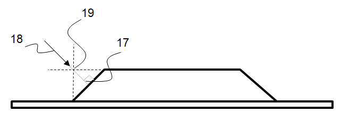
도 6은 테이퍼된 가장자리를 메울 수 있는 방법을 보여주는 부분적으로 형성된 물체의 개략 측면도;
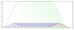
도 7은 콜드 스프레이드 레이어가 서로 인접한 라인들을 스프레잉하여 쌓여질 수 있는 방법을 나타낸 개략 단면도;
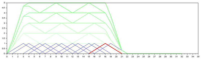
도 8은 인접하게 스프레이하는 대신, 적절한 표면 영각을 위해 스프레이 라인들을 인터리브하여 콜드 스프레이 레이어가 쌓일 수 있는 상기 방법을 나타낸 개략 단면도이다.Some preferred examples of this invention will be described with reference to examples and the accompanying drawings:
1 is an isometric view of a 3D cold spray printer;
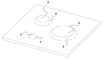
Fig. 2 is an isometric view of a first layer of each of the three 3D objects partially created by the printer;
3 is an isometric view of partially created objects at a more advanced stage;
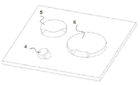
Fig. 4 is an isometric view of the three objects, partially created, with two layers almost complete;
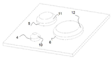
5 is an isometric view of an additional object formed in several layers by the printer;
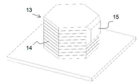
6 is a schematic side view of a partially formed object showing how a tapered edge may be filled;
7 is a schematic cross-sectional view illustrating how a cold spray layer may be deposited by spraying lines adjacent to each other;
8 is a schematic cross-sectional view illustrating the above method in which a cold spray layer may be deposited by interleaving the spray lines for proper surface angle of attack, instead of spraying adjacently.
도 1을 참조하면, 콜드 스프레이 3D 프린터(1)는 적합한 금속 분말 스프레이를 고속으로 배출하기 위한 노즐(2)을 포함하는 도포용구를 갖는다. 콜드 스프레이용 분말들에는 많은 종류가 있으며, 당업자는 이것들에 익숙할 것이다. 상기 금속 분말은 3D 물체를 생성하기 위해 로봇팔(3)을 갖는 기판 홀더에 의해 고정된 기판(도시되지 않은)에 스프레이된다. 더 구체적으로, 상기 물체는 순차적으로 스프레이된 일련의 평행 레이어들에 의해서 형성된다. Referring to Figure 1, a cold
상기 부분-형성된 3D 물체가 어떠한 방향 및 각도로도 움직일 수 있도록, 상기 로봇팔(3)은 상기 기판을 움직일 수 있는 것이 선호된다. 도 1의 실시예에서의 상기 노즐(2)은 고정되어있지만, 다른 실시예들에서는 어떠한 방향 또는 각도로도 스프레이 할 수 있도록 움직여질 수 있다.Preferably, the
도 2는 판 모양의 기판 위의 세개의 부분 형성된 3D 물체들의 제 1 레이어(4, 5, 6)를 나타낸다. 상기 스프레이 입자들이 노즐(2)에서 원뿔 형태로 이동함에 따라서, 상기 주변부에서 보다 상기 중심부에서 더 집중되어 더 빠르게 이동한다. 그 결과, 분말의 상기 증착은 일정하지않다. 이는 상기 레이어들(4, 5, 및 6)이 내측으로 테이퍼된 모서리들(7, 8, 9)을 갖게한다. 상기 테이퍼들은 실린더, 또는 다른 형태의 직선 모서리를 갖는 물체를 만들고자 하는 경우 바람직하지 못하다. 상기 기판 및 상기 부분 형성된 3D 물체가 상기 노즐에 대하여 적합한 각도 및 거리에 위치하도록 적절하게 상기 노즐(2) 및/또는 상기 팔(3)을 조정하여 상기 테이퍼들이 채워진다. 도 3은 상기 세개의 레이어들(4, 5, 6)의 테이퍼들이 스프레이 물질로 부분적으로 채워진 것을 나타낸다.2 shows a
도 4는 테이퍼들이 완전히 채워진 상기 제 1 레이어들(4, 5, 6) 및 상기 노즐(2)에 의해 스프레이로 형성된 쌓여진 상부 제 2 레이어(10, 11, 12)를 나타낸다. 각각의 케이스에서, 상기 제 2 레이어는 상기 제 1 레이어에 평행하며, 채워져야할 테이퍼된 모서리를 갖는다. 상기 테이퍼들은 상기 제 1 레이어들에서와 같은 방법으로 채워진다. 각 케이스에서 3D 실린더가 형성될 때까지 후속 평행 레이어에 대한 상기 과정이 반복된다.FIG. 4 shows the
도 5는 육각 횡단 단면을 갖는 완성된 3D 물체(13)를 나타낸다. 이와 관련하여, 상기 노즐(2) 및/또는 로봇 팔(3) / 기판을 적절하게 제어하여 곧은 면들(14) 및 돌출부들(15)을 갖는 물건들을 만들 수 있다.5 shows the finished
도 1을 다시 참조하면, 상기 프린터는 컴퓨터화된 컨트롤러(16)를 포함하거나 또는 연결되어있다. 상기 컴퓨터화된 컨트롤러(16)는 상기 3D 물체가 프린트 될 수 있도록 상기 노즐(20 및/또는 상기 로봇 팔(3) / 기판 사이의 거리 및 각도를 점진적으로 조정하는 지시들을 내린다. 이는 상기 노즐이 작업중인 상기 표면에 직각이 되도록 보장하는 것을 포함한다. 이 점에서, 상기 컨트롤러(16)는 상기 3D 물체의 상기 형태를 정의하는 데이터 파일(예시: .STL 확장자 형태의)과 상호작용을 하는 소프트웨어를 실행한다. 즉 상기 데이터는 일련의 작동 명령을 상기 소프트웨어에 제공한다.Referring back to FIG. 1 , the printer includes or is coupled to a
상기 데이터는 일련의 슬라이스들로 상기 3D 물체의 상기 형태를 정의하며, 상기 슬라이스들은 위에서 언급된 상기 레이어들 중 하나에 각각 상응한다. 테이퍼를 횡 증착 스트로크로 채우기 위해 상기 노즐(2) 및 또는 로봇팔(3) / 기판을 제어할 때, 상기 컨트롤러(16)는 상기 최적의 노즐 영각 및 상기 테이퍼 까지의 거리를 상기 개념상의 스택 내의 다음 슬라이스 또는 단면의 파라미터들에 기초하여 계산 및 결정한다. 상기 다음 슬라이스의 상기 토대는 아래의 상기 테이퍼를 채우기 위한 개념상의 경계를 표시하기 위하여 사용될 수 있다. 상기 컨트롤러(16)는 스프레이 지속시간, 분말의 공급 속도, 스프레이 속도, 상기 분말/스프레이의 온도, 및사용되는 스프레이 물질의 유형에 대한 상기 필수 스프레이 파라미터들 또한 계산한다.The data defines the shape of the 3D object as a series of slices, each of which corresponds to one of the layers mentioned above. When controlling the
예를 들어 상기 컨트롤러 및/또는 상기 노즐(2) 및/또는 상기 로봇 팔(3)이 세 차원 중 어느 방향으로도 움직일 수 있게 하는 기계 부품들을 포함하는 경우, 상기 노즐(2) 및/또는 상기 로봇 팔(3) / 기판은 상기 컨트롤러에 의해 직접적으로 움직여질 수 있다. 그러나, 다른 실시예들에서 상기 컨트롤러(16)는 상기 노즐 및 상기 로봇 팔(3) / 기판을, 예를 들어 상기 동일 3 차원 움직임을 위해 다축 포지셔닝 장치를 조종하여 간접적으로 움직일 수 있다.The
바람직하게, 각각의 레이어에 대한 충전은 상기 기판에 평행하는 평평한 상면을 얻기 위해 이루어진다. 그러나, 이는 필수적인 것이 아니며, 몇몇의 경우들에있어서는 대안 접근법을 채택할 수 있다.Preferably, the filling of each layer is made to obtain a flat top surface parallel to the substrate. However, this is not essential and an alternative approach may be adopted in some cases.
본 발명의 몇몇 실시예들에서, 각각의 레이어들의 테두리가 형성됨에 따라 각각의 레이어들의 테두리를 측정하는 레이저 라인 스캐너, 입체 영상기, 또는 구조화된 광카메라와 같은 수단을 추가시켜 정확도를 향상시킬 수 있다. 상기 측정값들은 상기 컨트롤러(16)에 실시간으로 전달되어 상기 노즐, 기판 또는 스프레이 파라미터들의 상기 작동의 계산 및 조정을 유발하기 위해 사용된다. In some embodiments of the present invention, the accuracy may be improved by adding means such as a laser line scanner, a stereoscopic imager, or a structured optical camera that measures the edges of each layer as the edges of each layer are formed. have. The measurements are communicated in real time to the
도 6은 상기 테이퍼된 모서리들을 채워넣는 바람직한 방법을 도시한다. 이와 관련하여, 상기 컨트롤러(16)는 상기 노즐(2)이 상기 "툴 경로" 내의 각각의 테이퍼부 둘레의 주위에 상기 필요한 충진을 제공하기 위해 스프레이하도록한다. 상기 로봇 팔(3) / 기판이 움직임에 따라, 상기 컨트롤러는 상기 부분-형성된 3D 물체의 상기 테이퍼된 모서리가 상기 노즐(2)의 상기 메인 스프레이축에 수직어 유지되도록한다. 상기 각도의 상기 수직 성질은 17에 표시되어있다. 상기 움직임은 상기 노즐의 상기 개념적 길이축들(18)은 상기 테이퍼가 채워지면 상기 물체의 모서리가 위치할 상기 포인트(19)를 통과하는 것과 같은 것이다. 6 shows a preferred method of filling the tapered corners. In this regard, the
당해 발명의 바람직한 형태들에서, 상기 스프레이 노즐(2)을 통과한 상기 로봇팔(3) / 기판의 범위는 상기 컨트롤러(16)에 의해 제어되어 스프레이 물질의 인터리브된 라인들을 증착한다. 일부의 응용에서, 이는 침전비를 향상시킬 수 있다.In preferred forms of the invention, the extent of the
도 7은 각각의 라인들이 인접하여 스프레이되었을 때, 콜드 스프레이 물질의 일련의 라인들을 통해 레이어를 선택적으로 작성하는 방법을 나타낸 단면 도식도이다. 상기 'x'축은 기판을 가로지르는 직선 거리를 밀리미터 단위로 나타내며, 상기 'y'축은 상기 노즐 및 상기 기판 사이의 높이 간격을 밀리미터 단위로 나타낸 것이다. 상기 'x' 축을 따라서 있는 삼각형들은 상기 각각의 라인들이 어디에 위치하는지를 나타내며, 또한 상기 단면 또는 증착된 물질의 스프레드를 표시한다. 상기 더 높고 평탄한 곡선들은 상기 라인들이 스프레이됨에 따라서 실질적으로 형성되는 소재의 통합량을 나타낸다. 상기 라인들이 인접하여 도포됨에 따라서, 상기 스프레이가 상기 표면에 부딪히는 상기 각도는 비스듬하여 상기 증착비를 최소화한다.7 is a schematic cross-sectional diagram illustrating a method of selectively building a layer through a series of lines of cold spray material when each of the lines is sprayed adjacently. The 'x' axis represents a straight line distance across the substrate in millimeters, and the 'y' axis represents a height interval between the nozzle and the substrate in millimeters. The triangles along the 'x' axis indicate where each of the lines is located, and also indicate the cross-section or spread of the deposited material. The higher and flatter curves represent the amount of material incorporated that is actually formed as the lines are sprayed. As the lines are applied adjacently, the angle at which the spray strikes the surface is oblique to minimize the deposition rate.
도 8은 콜드 스프레이된 물체의 라인들이 인접하여 스프레이된 경우에 어떻게 증착될 수 있는지의 단면도이다. 상기 'x' 축은 상기 기판을 가로 지르는 직선 거리를 밀리미터 단위로 나타낸 것이며, 상기 'y' 축은 기판으로 부터의 직선 높이를 나타낸 것이다. 상기 'x' 축을 따라 있는 삼각형들은 개별 라인들이 어디에 있는지를 나타내며, 증착된 물체의 교차지역을 표시한다. 상기 더 높은 곡선은 상기 라인들이 스프레이됨에 따라 형성되는 물체의 통합적인 양을 나타낸다. 상기 라인들이 인접하는 방식 대신에, 인터리브 방식으로 스프레이됨에 따라, 상기 통합 용량은 더 평평하게 형성된다.8 is a cross-sectional view of how lines of a cold sprayed object may be deposited if sprayed adjacently. The 'x' axis represents a straight line distance across the substrate in millimeters, and the 'y' axis represents a straight line height from the substrate. The triangles along the 'x' axis indicate where the individual lines are and mark the intersection of the deposited object. The higher curve represents the aggregate amount of object formed as the lines are sprayed. As the lines are sprayed in an interleaved manner instead of in a contiguous manner, the integrated capacitance is made flatter.
몇몇의 바람직한 실시예들이 예시로서 기술되었으나, 당해 발명의 범위에서 벗어나지 않는 선에서 수정안들 및 향상안들이 발생할 수 있음이 인식되어야한다.Although several preferred embodiments have been described by way of illustration, it should be recognized that modifications and improvements may occur without departing from the scope of the invention.
Claims (10)
물체의 3D 형상 파라미터들을 정의하는 데이터를 참조하여 제어 수단을 작동시키는 단계를 포함하고,
상기 제어 수단은 상기 데이터를 도포용구 및/또는 기판 홀더를 제어하여 스프레이 물질이 상기 기판에, 또한 그 후에는 부분 형성된 물체에 스프레이되도록 하여 점진적으로 도포된 레이어들에서 상기 물체를 만들어내기 위해 상기 데이터를 사용하며;
상기 레이어들의 적어도 일부는 초기 내측으로 테이퍼된 외부면을 가지며; 또한
상기 레이어들 중 적어도 일부에 대하여, 상기 제어 수단은 상기 테이터를 사용하여 도포용구로 하여금 스프레이 물질을 도포해 상기 데이터를 채우는,
방법.A method for forming a 3D object, comprising:
actuating the control means with reference to data defining the 3D shape parameters of the object;
The control means may transmit the data to control the applicator and/or the substrate holder so that a spray material is sprayed onto the substrate and thereafter onto the partly formed object to produce the object in progressively applied layers. is used;
at least some of the layers have an initially inwardly tapered outer surface; In addition
For at least some of the layers, the control means uses the data to cause an applicator to apply a spray material to fill the data.
Way.
상기 스프레이는 금속 분말을 포함하는 콜드 스프레이인,
방법.The method of claim 1,
The spray is a cold spray containing metal powder,
Way.
상기 테이퍼를 채우는 것은 상기 제어 수단을 통해:
상기 스프레이의 특성들에 기반하여 상기 테이퍼의 파라미터들을 계산하는 것, 상기 테이퍼를 채우기에 적절한 상기 도포용구 및 테이퍼 사이의 각도를 계산하는 것, 또한 상기 도포용구 및 테이퍼가 상기 각도에 위치하도록하며 상기 도포용구가 상기 테이퍼에 스프레이 물질을 도포하도록 하는 것을 포함하는,
방법.The method of claim 1,
Filling the taper is via the control means:
calculating the parameters of the taper based on the properties of the spray, calculating an angle between the applicator and the taper suitable to fill the taper, and placing the applicator and the taper at the angle, and causing an applicator to apply a spray material to the taper;
Way.
상기 데이터는 일련의 상기 레이어들의 관점으로 상기 3D 물체를 정의하며, 또한
상기 제어 수단은 상기 테이퍼를 스프레이로 채우기 위해 상기 도포용구 및 테이퍼 사이의 상기 각도를 제어하기 위해 다음 레이어의 미리-정의된 파라미터들을 사용하는,
방법.The method of claim 1,
the data defines the 3D object in terms of a series of said layers, and
the control means using pre-defined parameters of the next layer to control the angle between the applicator and the taper to fill the taper with spray;
Way.
표면 스캐너는 상기 물체가 만들어짐에 따라서 상기 물체를 반복적으로 측정하며,
상기 제어 수단은 상기 물체(부분 형성된 때) 및 상기 노즐의 상대적인 위치들을 조정하거나, 상기 노즐의 스프레이 파라미터를 조정하거나, 상기 물체(부분 형성된 때) 및 상기 노즐의 상대적인 위치들을 조정하면서 상기 노즐의 스프레이 파라미터를 조정하여 상기 형상 파라미터들과 완성된 상기 물체 사이의 일치의 정확성을 높이기 위해 상기 측정값들을 사용하는,
방법.5. The method of claim 4,
The surface scanner repeatedly measures the object as it is made,
The control means adjusts the relative positions of the object (when partially formed) and the nozzle, adjusts the spray parameter of the nozzle, or adjusts the relative positions of the object (when partially formed) and the nozzle while spraying the nozzle using the measurements to adjust parameters to increase the accuracy of the match between the shape parameters and the finished object;
Way.
컴퓨터화된 컨트롤러를 물체의 3D 형상 파라미터들을 개념적 슬라이스들의 관점으로 정의하는 데이터를 참조하여 작동시키는 단계를 포함하고,
상기 컨트롤러는 상기 데이터를 사용하여 도포용구가 금속 분말을 포함하는 물질을 기판에, 그 다음에는 부분-형성된 상기 물체에, 인접하는 라인들에 스프레이하여 상기 슬라이스들에 대응하는 점진적으로 도포된 레이어들로 상기 물체를 만들며,
상기 레이어들의 적어도 일부는 초기 내측으로 테이퍼된 외부면을 가지며; 또한
상기 레이어들 중 적어도 일부에 대하여, 상기 컨트롤러는 상기 테이터를 사용하여 도포용구로 하여금 상기 테이퍼에 수직으로 도포하도록 하여 상기 데이터를 채우는,
방법.A method for forming a 3D object, comprising:
operating the computerized controller with reference to data defining 3D shape parameters of the object in terms of conceptual slices;
The controller uses the data to enable an applicator to spray a material comprising metal powder onto a substrate, then on the partially-formed object, in adjacent lines, to apply progressively applied layers corresponding to the slices. to make the object with
at least some of the layers have an initially inwardly tapered outer surface; In addition
For at least some of the layers, the controller uses the data to cause an applicator to apply perpendicular to the taper to fill the data.
Way.
각각의 라인을 위해 스프레이된 상기 물질이 하나 또는 그 이상의 이웃하는 라인들을 위해 스프레이된 물질과 인터리빙하는.
방법.7. The method of claim 6,
wherein the material sprayed for each line interleaves with the material sprayed for one or more neighboring lines.
Way.
표면 스캐너는 상기 물체가 생성됨에 따라서 상기 물체를 반복적으로 측정하며, 또한
상기 컨트롤러는 상기 측정값들을 사용하여 도포용구 및/또는 기판 및/또는 스프레이 파라미터들을 조정하여 완성되었을 때의 상기 형상 파라미터들과 상기 물체 사이의 일치의 정확성을 높이기 위해 상기 측정값을 사용하는,
방법.8. The method of claim 7,
The surface scanner repeatedly measures the object as it is created, and also
the controller uses the measurements to adjust applicator and/or substrate and/or spray parameters using the measurements to increase the accuracy of the match between the shape parameters and the object when finished;
Way.
상기 스프레이는 금속 분말을 포함하는 콜드스프레이 이며;
상기 테이퍼를 채우는 단계에서 상기 스프레이의 특성에 기반하여 상기 테이퍼의 상기 파라미터를 계산하며, 상기 테이퍼를 채우기에 적합한 상기 도포용구 및 테이퍼 사이의 각도를 계산하며, 또한 상기 도포용구 및 테이퍼가 상기 각도에 있도록 하며 또한 상기 도포용구가 상기 테이퍼세 스프레이 물질을 도포하도록 하는 상기 제어 수단을 수반하며;
상기 데이터는 일련의 상기 레이어들의 관점으로 상기 3D 물체를 정의하며, 상기 제어 수단은 상기 테이퍼를 스프레이로 채우기 위하여 상기 도포용구 및 테이퍼 사이의 상기 각도를 조정하기 위해 상기 다음 레이어의 사전-정의된 파라미터들을 사용하며; 또한
상기 제어 수단은 상기 물체(부분 형성된 때) 및 상기 노즐의 상대적인 위치들을 조정하거나, 상기 노즐의 스프레이 파라미터를 조정하거나, 상기 물체(부분 형성된 때) 및 상기 노즐의 상대적인 위치들을 조정하면서 상기 노즐의 스프레이 파라미터를 조정하여 상기 형상 파라미터들과 완성된 상기 물체 사이의 일치의 정확성을 높이기 위해 상기 측정값들을 사용하는,
방법.The method of claim 1,
The spray is a cold spray containing metal powder;
In the step of filling the taper, the parameter of the taper is calculated based on the properties of the spray, the angle between the applicator and the taper suitable for filling the taper is calculated, and the applicator and the taper are at the angle. and carrying said control means for causing said applicator to apply said tapered spray material;
The data defines the 3D object in terms of a series of said layers, the control means pre-defined parameters of the next layer to adjust the angle between the applicator and the taper to fill the taper with spray use them; In addition
The control means adjusts the relative positions of the object (when partially formed) and the nozzle, adjusts the spray parameter of the nozzle, or adjusts the relative positions of the object (when partially formed) and the nozzle while spraying the nozzle using the measurements to adjust parameters to increase the accuracy of the match between the shape parameters and the finished object;
Way.
컴퓨터화된 제어 수단; 물체의 3D 형상 파라미터들을 정의하는 전자 데이터; 도포용구; 및 기판 홀더를 포함하며,
제어 수단은:
상기 데이터를 사용하여 상기 도포용구 및/또는 상기 기판 홀더를 상기 기판 및 그 후에는 부분-형성된 물체에 스프레이하도록 제어하여 점진적으로 도포된 레이어들로 상기 물체를 만들도록 조정되며,
상기 레이어들 중 적어도 일부에 대하여, 상기 제어 수단은 상기 테이터를 사용하여 도포용구로 하여금 스프레이 물질을 도포해 상기 데이터를 채우는,
프린터.
A printer for forming 3D objects, comprising:
computerized control means; electronic data defining the 3D shape parameters of the object; applicator; and a substrate holder,
Control means:
using said data to control said applicator and/or said substrate holder to spray onto said substrate and thereafter partially-formed object to make said object with progressively applied layers;
For at least some of the layers, the control means uses the data to cause an applicator to apply a spray material to fill the data.
printer.
Applications Claiming Priority (4)
| Application Number | Priority Date | Filing Date | Title |
|---|---|---|---|
| AU2016904106 | 2016-10-11 | ||
| AU2016904106A AU2016904106A0 (en) | 2016-10-11 | A Method of Forming 3D Objects | |
| KR1020197011562A KR20190067814A (en) | 2016-10-11 | 2017-10-05 | How to create 3D objects |
| PCT/AU2017/051083 WO2018068082A1 (en) | 2016-10-11 | 2017-10-05 | A method of forming 3d objects. |
Related Parent Applications (1)
| Application Number | Title | Priority Date | Filing Date |
|---|---|---|---|
| KR1020197011562A Division KR20190067814A (en) | 2016-10-11 | 2017-10-05 | How to create 3D objects |
Publications (1)
| Publication Number | Publication Date |
|---|---|
| KR20220080200A true KR20220080200A (en) | 2022-06-14 |
Family
ID=61904955
Family Applications (2)
| Application Number | Title | Priority Date | Filing Date |
|---|---|---|---|
| KR1020197011562A KR20190067814A (en) | 2016-10-11 | 2017-10-05 | How to create 3D objects |
| KR1020227018342A KR20220080200A (en) | 2016-10-11 | 2017-10-05 | A method of forming 3d objects |
Family Applications Before (1)
| Application Number | Title | Priority Date | Filing Date |
|---|---|---|---|
| KR1020197011562A KR20190067814A (en) | 2016-10-11 | 2017-10-05 | How to create 3D objects |
Country Status (9)
| Country | Link |
|---|---|
| US (1) | US20190316262A1 (en) |
| EP (1) | EP3526044A4 (en) |
| JP (1) | JP7092756B2 (en) |
| KR (2) | KR20190067814A (en) |
| CN (1) | CN109843591B (en) |
| AU (2) | AU2017342702B2 (en) |
| BR (1) | BR112019007190B1 (en) |
| RU (1) | RU2019113774A (en) |
| WO (1) | WO2018068082A1 (en) |
Families Citing this family (5)
| Publication number | Priority date | Publication date | Assignee | Title |
|---|---|---|---|---|
| US10569459B2 (en) * | 2016-04-23 | 2020-02-25 | Robotic Research, Llc | Handheld 3D printer |
| US11269311B2 (en) * | 2018-07-26 | 2022-03-08 | Divergent Technologies, Inc. | Spray forming structural joints |
| CN112969820A (en) * | 2018-11-07 | 2021-06-15 | 易福仁科技知产私人有限公司 | 3D printing method |
| KR102191296B1 (en) * | 2018-11-15 | 2020-12-15 | 한밭대학교 산학협력단 | Hybrid binder jet 3D printing apparatus and method for making possible of freeform architecture using different viscosity |
| CN111962059B (en) * | 2020-08-24 | 2022-09-30 | 西北工业大学 | Solid-state 3D printing system and method for on-orbit manufacturing and repairing of space member by cold spraying |
Family Cites Families (32)
| Publication number | Priority date | Publication date | Assignee | Title |
|---|---|---|---|---|
| DE69115380T2 (en) * | 1990-08-09 | 1996-06-13 | Ici Plc | Spraying liquids |
| JP3091316B2 (en) * | 1992-05-26 | 2000-09-25 | 松下電工株式会社 | 3D shape forming method |
| US6296043B1 (en) * | 1996-12-10 | 2001-10-02 | Howmet Research Corporation | Spraycast method and article |
| US20040222310A1 (en) * | 2003-05-07 | 2004-11-11 | Lear Corporation | Method of spray polyurethane application utilizing internally mixed components applied with a flat fan spray |
| CN201143468Y (en) * | 2008-01-09 | 2008-11-05 | 中国船舶重工集团公司第七二五研究所 | Laval nozzle for cold spraying |
| US20100170937A1 (en) * | 2009-01-07 | 2010-07-08 | General Electric Company | System and Method of Joining Metallic Parts Using Cold Spray Technique |
| JP5289990B2 (en) * | 2009-01-28 | 2013-09-11 | 日立建機株式会社 | Method for modifying the surface of a round shaft and reformer used therefor |
| JP5318605B2 (en) | 2009-02-06 | 2013-10-16 | 安川情報システム株式会社 | Operating time management system |
| US20120269958A1 (en) * | 2009-10-27 | 2012-10-25 | Ramesh Subramanian | Material buildup simulations by application of powder jet mass conservation priciples |
| JP5877590B2 (en) * | 2010-12-22 | 2016-03-08 | プラズマ技研工業株式会社 | Cold spray nozzle and cold spray device using the cold spray nozzle |
| KR20140108268A (en) * | 2011-12-16 | 2014-09-05 | 에이치. 씨. 스타아크 아이앤씨 | Spray rejuvenation of sputtering targets |
| JP2013142176A (en) * | 2012-01-11 | 2013-07-22 | Toyota Motor Corp | Apparatus and method for adjusting nozzle position of cold spray |
| US9765435B2 (en) * | 2012-04-04 | 2017-09-19 | Commonwealth Scientific And Industrial Research Organisation | Process for producing a titanium load-bearing structure |
| DE102012008664B4 (en) * | 2012-05-03 | 2015-10-01 | Cl Schutzrechtsverwaltungs Gmbh | Method for filling a metering chamber and device therefor |
| DE102013216439A1 (en) * | 2013-05-22 | 2014-11-27 | Siemens Aktiengesellschaft | Method for producing a cup-shaped component and production plant suitable for the use of this method |
| FR3006606B1 (en) * | 2013-06-11 | 2015-07-03 | Tech Avancees Et Membranes Industrielles | PROCESS FOR MANUFACTURING FILTRATION MEMBRANES BY ADDITIVE TECHNIQUE AND MEMBRANES OBTAINED |
| US9604412B2 (en) * | 2013-07-12 | 2017-03-28 | Xerox Corporation | Digital manufacturing system for printing three-dimensional objects on a rotating surface |
| JP6259602B2 (en) * | 2013-07-31 | 2018-01-10 | グローリー株式会社 | Paper sheet bundling device |
| US9855698B2 (en) * | 2013-08-07 | 2018-01-02 | Massachusetts Institute Of Technology | Automatic process control of additive manufacturing device |
| JP6578563B2 (en) * | 2013-11-06 | 2019-09-25 | ラトガーズ、ザ ステイト ユニバーシティ オブ ニュージャージー | Production of monolithic body from porous matrix using low temperature solidification in additive manufacturing process |
| CN103786342A (en) * | 2014-01-10 | 2014-05-14 | 康子纯 | 3D (three-dimensional) printer with inclinable machine body |
| BR112016028857B1 (en) * | 2014-06-09 | 2021-08-24 | Hybrid Manufacturing Technologies Limited | MACHINE TOOL, METHODS FOR CREATING AND INSPECTING AN ARTICLE, AND, PROCESSING HEAD |
| EP3159141A4 (en) * | 2014-06-20 | 2018-01-24 | Fujimi Incorporated | Powder material to be used in powder lamination shaping and powder lamination shaping method using same |
| WO2016039399A1 (en) * | 2014-09-10 | 2016-03-17 | 日本発條株式会社 | Laminate and laminate manufacturing method |
| JP2018029090A (en) * | 2014-11-26 | 2018-02-22 | 株式会社日立製作所 | Junction structure of different types of metals, method for forming the structure, and water-cooling power conversion element having the structure |
| US9895845B2 (en) * | 2015-02-16 | 2018-02-20 | Arevo Inc. | Method and a system to optimize printing parameters in additive manufacturing process |
| CN104760284A (en) * | 2015-03-17 | 2015-07-08 | 百度在线网络技术(北京)有限公司 | 3D-printing head and 3D printer |
| US20160325498A1 (en) * | 2015-05-04 | 2016-11-10 | Daniel Gelbart | 3D Printer Based on a Staggered Nozzle Array |
| CN104985813B (en) | 2015-06-23 | 2017-03-08 | 同济大学 | A kind of 3D printing method and system based on cold spraying |
| US10532552B2 (en) * | 2015-10-23 | 2020-01-14 | Makerbot Industries, Llc | Build patterns for surfaces of a three-dimensionally printed object |
| US11059217B2 (en) * | 2015-11-23 | 2021-07-13 | Frank A. McKiel, Jr. | Method and apparatus for transposing extruded materials to fabricate an object surface |
| CN205587662U (en) * | 2016-02-25 | 2016-09-21 | 昆明理工大学 | Metal material continuous working device |
-
2017
- 2017-10-05 CN CN201780063158.5A patent/CN109843591B/en active Active
- 2017-10-05 AU AU2017342702A patent/AU2017342702B2/en active Active
- 2017-10-05 US US16/340,737 patent/US20190316262A1/en active Pending
- 2017-10-05 KR KR1020197011562A patent/KR20190067814A/en not_active Application Discontinuation
- 2017-10-05 RU RU2019113774A patent/RU2019113774A/en not_active Application Discontinuation
- 2017-10-05 KR KR1020227018342A patent/KR20220080200A/en not_active IP Right Cessation
- 2017-10-05 BR BR112019007190-3A patent/BR112019007190B1/en active IP Right Grant
- 2017-10-05 JP JP2019518914A patent/JP7092756B2/en active Active
- 2017-10-05 WO PCT/AU2017/051083 patent/WO2018068082A1/en unknown
- 2017-10-05 EP EP17860372.6A patent/EP3526044A4/en active Pending
-
2023
- 2023-04-19 AU AU2023202406A patent/AU2023202406A1/en not_active Abandoned
Also Published As
| Publication number | Publication date |
|---|---|
| JP2019537523A (en) | 2019-12-26 |
| BR112019007190B1 (en) | 2022-11-01 |
| RU2019113774A (en) | 2020-11-13 |
| EP3526044A4 (en) | 2020-06-24 |
| US20190316262A1 (en) | 2019-10-17 |
| JP7092756B2 (en) | 2022-06-28 |
| WO2018068082A1 (en) | 2018-04-19 |
| AU2017342702B2 (en) | 2023-05-11 |
| KR20190067814A (en) | 2019-06-18 |
| BR112019007190A2 (en) | 2019-07-02 |
| AU2017342702A1 (en) | 2019-05-16 |
| CN109843591B (en) | 2022-02-08 |
| EP3526044A1 (en) | 2019-08-21 |
| AU2023202406A1 (en) | 2023-05-11 |
| CN109843591A (en) | 2019-06-04 |
Similar Documents
| Publication | Publication Date | Title |
|---|---|---|
| KR20220080200A (en) | A method of forming 3d objects | |
| JP7110399B2 (en) | Slicing method with variable thickness, 3D printing method and 3D printed product | |
| Jin et al. | A parallel-based path generation method for fused deposition modeling | |
| TWI580095B (en) | 3-d patterning method using laser | |
| US10059056B2 (en) | Micro-dispensing multi-layered 3D objects with curing steps | |
| US20170326792A1 (en) | Method, Device, and Recoating Module for Producing a Three-Dimensional Object | |
| JP6384826B2 (en) | Three-dimensional additive manufacturing apparatus, three-dimensional additive manufacturing method, and three-dimensional additive manufacturing program | |
| JP7189136B2 (en) | 3D printing method and 3D printing apparatus | |
| NL1041597B1 (en) | Method for optimized manufacturing. | |
| CN110475633B (en) | Method and device for controlling an irradiation system for workpiece production | |
| CN107529489A (en) | Untouched control for the layering of three dimensional object printing | |
| US10864675B2 (en) | Method for the layered construction of a shaped body | |
| US10967564B2 (en) | Method for the layered construction of a shaped body | |
| EP3246148B1 (en) | Additive layer manufacturing base plate | |
| JP3923511B1 (en) | Stereolithography method | |
| CN106925776A (en) | A kind of subregion scanning pattern generation method of control increasing material manufacturing stress deformation | |
| KR20160148075A (en) | An Manufacturing Method of 3 Dimensional Shape | |
| KR102152465B1 (en) | Apparatus and method for powder control of 3D printing system | |
| EP2377641B1 (en) | Method and apparatus for Manufacturing a Component | |
| JP6878364B2 (en) | Movable wall for additional powder floor | |
| KR102012236B1 (en) | Method of manufacturing three dimensional shapes using laser and metal powder | |
| JP2022506643A (en) | Alternating double-layer contouring and hatching for 3D manufacturing | |
| KR101683799B1 (en) | The 3-dimensional shape manufacturing method using region segmentation and beam spot size and velocity adjustment | |
| Baev et al. | Method of crack-free laser writing of microchannels on glass substrates | |
| US20190134912A1 (en) | Setting printing distances |
Legal Events
| Date | Code | Title | Description |
|---|---|---|---|
| A107 | Divisional application of patent | ||
| E902 | Notification of reason for refusal | ||
| AMND | Amendment | ||
| E601 | Decision to refuse application | ||
| X091 | Application refused [patent] | ||
| AMND | Amendment | ||
| X601 | Decision of rejection after re-examination |