KR20220059947A - polarizer - Google Patents
polarizer Download PDFInfo
- Publication number
- KR20220059947A KR20220059947A KR1020227008162A KR20227008162A KR20220059947A KR 20220059947 A KR20220059947 A KR 20220059947A KR 1020227008162 A KR1020227008162 A KR 1020227008162A KR 20227008162 A KR20227008162 A KR 20227008162A KR 20220059947 A KR20220059947 A KR 20220059947A
- Authority
- KR
- South Korea
- Prior art keywords
- polarizer
- boric acid
- polarizing plate
- region
- iodine
- Prior art date
Links
- 239000004327 boric acid Substances 0.000 claims abstract description 106
- KGBXLFKZBHKPEV-UHFFFAOYSA-N boric acid Chemical compound OB(O)O KGBXLFKZBHKPEV-UHFFFAOYSA-N 0.000 claims abstract description 96
- ZCYVEMRRCGMTRW-UHFFFAOYSA-N 7553-56-2 Chemical compound [I] ZCYVEMRRCGMTRW-UHFFFAOYSA-N 0.000 claims abstract description 81
- 229910052740 iodine Inorganic materials 0.000 claims abstract description 81
- 239000011630 iodine Substances 0.000 claims abstract description 81
- 229920005989 resin Polymers 0.000 claims abstract description 80
- 239000011347 resin Substances 0.000 claims abstract description 80
- PNDPGZBMCMUPRI-UHFFFAOYSA-N iodine Chemical compound II PNDPGZBMCMUPRI-UHFFFAOYSA-N 0.000 claims abstract description 8
- 239000012788 optical film Substances 0.000 claims description 129
- 239000010408 film Substances 0.000 claims description 78
- 238000005520 cutting process Methods 0.000 claims description 44
- 238000000034 method Methods 0.000 claims description 38
- 238000004519 manufacturing process Methods 0.000 claims description 30
- 239000002585 base Substances 0.000 claims description 22
- 239000003637 basic solution Substances 0.000 claims description 17
- XLYOFNOQVPJJNP-UHFFFAOYSA-N water Substances O XLYOFNOQVPJJNP-UHFFFAOYSA-N 0.000 claims description 16
- HEMHJVSKTPXQMS-UHFFFAOYSA-M Sodium hydroxide Chemical compound [OH-].[Na+] HEMHJVSKTPXQMS-UHFFFAOYSA-M 0.000 claims description 15
- 238000000465 moulding Methods 0.000 claims description 10
- KWYUFKZDYYNOTN-UHFFFAOYSA-M Potassium hydroxide Chemical compound [OH-].[K+] KWYUFKZDYYNOTN-UHFFFAOYSA-M 0.000 claims description 9
- 150000007514 bases Chemical class 0.000 claims description 8
- 238000004080 punching Methods 0.000 claims description 8
- 239000000243 solution Substances 0.000 claims description 7
- 239000002904 solvent Substances 0.000 claims description 4
- 238000013459 approach Methods 0.000 claims description 2
- 230000007423 decrease Effects 0.000 claims description 2
- 230000002093 peripheral effect Effects 0.000 claims 1
- 238000009833 condensation Methods 0.000 abstract description 18
- 230000005494 condensation Effects 0.000 abstract description 18
- 230000035939 shock Effects 0.000 abstract description 13
- 238000012360 testing method Methods 0.000 abstract description 11
- 229960002645 boric acid Drugs 0.000 description 91
- 235000010338 boric acid Nutrition 0.000 description 91
- 239000012790 adhesive layer Substances 0.000 description 27
- 239000010410 layer Substances 0.000 description 25
- -1 boric acid ion Chemical class 0.000 description 23
- 239000004372 Polyvinyl alcohol Substances 0.000 description 21
- 229920002451 polyvinyl alcohol Polymers 0.000 description 21
- 239000004820 Pressure-sensitive adhesive Substances 0.000 description 16
- 239000000203 mixture Substances 0.000 description 16
- 238000005011 time of flight secondary ion mass spectroscopy Methods 0.000 description 14
- 238000002042 time-of-flight secondary ion mass spectrometry Methods 0.000 description 14
- 150000001875 compounds Chemical class 0.000 description 13
- 238000005259 measurement Methods 0.000 description 13
- 230000003287 optical effect Effects 0.000 description 13
- 229920001577 copolymer Polymers 0.000 description 11
- 238000004043 dyeing Methods 0.000 description 10
- 229920000089 Cyclic olefin copolymer Polymers 0.000 description 8
- 230000000052 comparative effect Effects 0.000 description 8
- 238000000879 optical micrograph Methods 0.000 description 7
- 238000010521 absorption reaction Methods 0.000 description 6
- 238000004458 analytical method Methods 0.000 description 6
- JRZJOMJEPLMPRA-UHFFFAOYSA-N olefin Natural products CCCCCCCC=C JRZJOMJEPLMPRA-UHFFFAOYSA-N 0.000 description 6
- 238000005406 washing Methods 0.000 description 6
- 239000000853 adhesive Substances 0.000 description 5
- 150000001336 alkenes Chemical class 0.000 description 5
- 229920002678 cellulose Polymers 0.000 description 5
- 238000001035 drying Methods 0.000 description 5
- 238000003475 lamination Methods 0.000 description 5
- 239000004973 liquid crystal related substance Substances 0.000 description 5
- 239000000178 monomer Substances 0.000 description 5
- 229920000515 polycarbonate Polymers 0.000 description 5
- 239000004417 polycarbonate Substances 0.000 description 5
- 230000001070 adhesive effect Effects 0.000 description 4
- 239000007864 aqueous solution Substances 0.000 description 4
- 150000001732 carboxylic acid derivatives Chemical class 0.000 description 4
- 238000010586 diagram Methods 0.000 description 4
- JFNLZVQOOSMTJK-KNVOCYPGSA-N norbornene Chemical compound C1[C@@H]2CC[C@H]1C=C2 JFNLZVQOOSMTJK-KNVOCYPGSA-N 0.000 description 4
- 229920000642 polymer Polymers 0.000 description 4
- 229920005672 polyolefin resin Polymers 0.000 description 4
- 238000012545 processing Methods 0.000 description 4
- LYCAIKOWRPUZTN-UHFFFAOYSA-N Ethylene glycol Chemical compound OCCO LYCAIKOWRPUZTN-UHFFFAOYSA-N 0.000 description 3
- XTXRWKRVRITETP-UHFFFAOYSA-N Vinyl acetate Chemical compound CC(=O)OC=C XTXRWKRVRITETP-UHFFFAOYSA-N 0.000 description 3
- 239000001913 cellulose Substances 0.000 description 3
- 239000003795 chemical substances by application Substances 0.000 description 3
- 238000004132 cross linking Methods 0.000 description 3
- 238000009826 distribution Methods 0.000 description 3
- 150000002500 ions Chemical class 0.000 description 3
- 238000010030 laminating Methods 0.000 description 3
- 125000002496 methyl group Chemical group [H]C([H])([H])* 0.000 description 3
- 229920001225 polyester resin Polymers 0.000 description 3
- 238000007493 shaping process Methods 0.000 description 3
- 150000005846 sugar alcohols Polymers 0.000 description 3
- 230000001629 suppression Effects 0.000 description 3
- 229920005992 thermoplastic resin Polymers 0.000 description 3
- 229920002554 vinyl polymer Polymers 0.000 description 3
- 230000000007 visual effect Effects 0.000 description 3
- 229920002126 Acrylic acid copolymer Polymers 0.000 description 2
- 239000004925 Acrylic resin Substances 0.000 description 2
- 229920000178 Acrylic resin Polymers 0.000 description 2
- 229920002284 Cellulose triacetate Polymers 0.000 description 2
- LFQSCWFLJHTTHZ-UHFFFAOYSA-N Ethanol Chemical compound CCO LFQSCWFLJHTTHZ-UHFFFAOYSA-N 0.000 description 2
- VGGSQFUCUMXWEO-UHFFFAOYSA-N Ethene Chemical compound C=C VGGSQFUCUMXWEO-UHFFFAOYSA-N 0.000 description 2
- 239000005977 Ethylene Substances 0.000 description 2
- KKEYFWRCBNTPAC-UHFFFAOYSA-N Terephthalic acid Chemical compound OC(=O)C1=CC=C(C(O)=O)C=C1 KKEYFWRCBNTPAC-UHFFFAOYSA-N 0.000 description 2
- NNLVGZFZQQXQNW-ADJNRHBOSA-N [(2r,3r,4s,5r,6s)-4,5-diacetyloxy-3-[(2s,3r,4s,5r,6r)-3,4,5-triacetyloxy-6-(acetyloxymethyl)oxan-2-yl]oxy-6-[(2r,3r,4s,5r,6s)-4,5,6-triacetyloxy-2-(acetyloxymethyl)oxan-3-yl]oxyoxan-2-yl]methyl acetate Chemical compound O([C@@H]1O[C@@H]([C@H]([C@H](OC(C)=O)[C@H]1OC(C)=O)O[C@H]1[C@@H]([C@@H](OC(C)=O)[C@H](OC(C)=O)[C@@H](COC(C)=O)O1)OC(C)=O)COC(=O)C)[C@@H]1[C@@H](COC(C)=O)O[C@@H](OC(C)=O)[C@H](OC(C)=O)[C@H]1OC(C)=O NNLVGZFZQQXQNW-ADJNRHBOSA-N 0.000 description 2
- 239000003963 antioxidant agent Substances 0.000 description 2
- 230000003078 antioxidant effect Effects 0.000 description 2
- 239000002216 antistatic agent Substances 0.000 description 2
- 230000015572 biosynthetic process Effects 0.000 description 2
- 238000010538 cationic polymerization reaction Methods 0.000 description 2
- 239000006059 cover glass Substances 0.000 description 2
- 239000003431 cross linking reagent Substances 0.000 description 2
- 238000013461 design Methods 0.000 description 2
- WOZVHXUHUFLZGK-UHFFFAOYSA-N dimethyl terephthalate Chemical compound COC(=O)C1=CC=C(C(=O)OC)C=C1 WOZVHXUHUFLZGK-UHFFFAOYSA-N 0.000 description 2
- 230000009477 glass transition Effects 0.000 description 2
- 229920001519 homopolymer Polymers 0.000 description 2
- 238000010884 ion-beam technique Methods 0.000 description 2
- QQVIHTHCMHWDBS-UHFFFAOYSA-N isophthalic acid Chemical compound OC(=O)C1=CC=CC(C(O)=O)=C1 QQVIHTHCMHWDBS-UHFFFAOYSA-N 0.000 description 2
- 230000010355 oscillation Effects 0.000 description 2
- 239000004014 plasticizer Substances 0.000 description 2
- 230000010287 polarization Effects 0.000 description 2
- 229920003229 poly(methyl methacrylate) Polymers 0.000 description 2
- 239000004926 polymethyl methacrylate Substances 0.000 description 2
- 239000011118 polyvinyl acetate Substances 0.000 description 2
- 229920002689 polyvinyl acetate Polymers 0.000 description 2
- 230000001681 protective effect Effects 0.000 description 2
- 238000005507 spraying Methods 0.000 description 2
- JIAARYAFYJHUJI-UHFFFAOYSA-L zinc dichloride Chemical compound [Cl-].[Cl-].[Zn+2] JIAARYAFYJHUJI-UHFFFAOYSA-L 0.000 description 2
- 229920003067 (meth)acrylic acid ester copolymer Polymers 0.000 description 1
- WTDBQJMMOXGIQZ-UHFFFAOYSA-N 3,4-dimethylnaphthalene-1,2-dicarboxylic acid Chemical compound C1=CC=C2C(C(O)=O)=C(C(O)=O)C(C)=C(C)C2=C1 WTDBQJMMOXGIQZ-UHFFFAOYSA-N 0.000 description 1
- BVKZGUZCCUSVTD-UHFFFAOYSA-L Carbonate Chemical compound [O-]C([O-])=O BVKZGUZCCUSVTD-UHFFFAOYSA-L 0.000 description 1
- 229920001747 Cellulose diacetate Polymers 0.000 description 1
- 239000004593 Epoxy Substances 0.000 description 1
- JOYRKODLDBILNP-UHFFFAOYSA-N Ethyl urethane Chemical compound CCOC(N)=O JOYRKODLDBILNP-UHFFFAOYSA-N 0.000 description 1
- OFOBLEOULBTSOW-UHFFFAOYSA-N Malonic acid Chemical compound OC(=O)CC(O)=O OFOBLEOULBTSOW-UHFFFAOYSA-N 0.000 description 1
- VVQNEPGJFQJSBK-UHFFFAOYSA-N Methyl methacrylate Chemical compound COC(=O)C(C)=C VVQNEPGJFQJSBK-UHFFFAOYSA-N 0.000 description 1
- 229920002845 Poly(methacrylic acid) Polymers 0.000 description 1
- 239000004743 Polypropylene Substances 0.000 description 1
- 239000004793 Polystyrene Substances 0.000 description 1
- QYKIQEUNHZKYBP-UHFFFAOYSA-N Vinyl ether Chemical class C=COC=C QYKIQEUNHZKYBP-UHFFFAOYSA-N 0.000 description 1
- ORLQHILJRHBSAY-UHFFFAOYSA-N [1-(hydroxymethyl)cyclohexyl]methanol Chemical compound OCC1(CO)CCCCC1 ORLQHILJRHBSAY-UHFFFAOYSA-N 0.000 description 1
- 239000006096 absorbing agent Substances 0.000 description 1
- 230000001133 acceleration Effects 0.000 description 1
- DHKHKXVYLBGOIT-UHFFFAOYSA-N acetaldehyde Diethyl Acetal Natural products CCOC(C)OCC DHKHKXVYLBGOIT-UHFFFAOYSA-N 0.000 description 1
- 150000001241 acetals Chemical class 0.000 description 1
- 150000003926 acrylamides Chemical class 0.000 description 1
- NIXOWILDQLNWCW-UHFFFAOYSA-N acrylic acid group Chemical group C(C=C)(=O)O NIXOWILDQLNWCW-UHFFFAOYSA-N 0.000 description 1
- 239000000654 additive Substances 0.000 description 1
- 230000000996 additive effect Effects 0.000 description 1
- 150000001299 aldehydes Chemical group 0.000 description 1
- 125000002723 alicyclic group Chemical group 0.000 description 1
- QGZKDVFQNNGYKY-UHFFFAOYSA-O ammonium group Chemical group [NH4+] QGZKDVFQNNGYKY-UHFFFAOYSA-O 0.000 description 1
- 230000003373 anti-fouling effect Effects 0.000 description 1
- 239000002518 antifoaming agent Substances 0.000 description 1
- 230000005540 biological transmission Effects 0.000 description 1
- CDQSJQSWAWPGKG-UHFFFAOYSA-N butane-1,1-diol Chemical compound CCCC(O)O CDQSJQSWAWPGKG-UHFFFAOYSA-N 0.000 description 1
- 150000001735 carboxylic acids Chemical class 0.000 description 1
- 230000015556 catabolic process Effects 0.000 description 1
- 239000012986 chain transfer agent Substances 0.000 description 1
- 238000006243 chemical reaction Methods 0.000 description 1
- 239000012141 concentrate Substances 0.000 description 1
- 238000001816 cooling Methods 0.000 description 1
- 238000003851 corona treatment Methods 0.000 description 1
- 125000004122 cyclic group Chemical group 0.000 description 1
- 238000006731 degradation reaction Methods 0.000 description 1
- 230000006866 deterioration Effects 0.000 description 1
- OVPXRLUTUWRYEY-UHFFFAOYSA-N dimethyl naphthalene-1,8-dicarboxylate Chemical compound C1=CC(C(=O)OC)=C2C(C(=O)OC)=CC=CC2=C1 OVPXRLUTUWRYEY-UHFFFAOYSA-N 0.000 description 1
- 150000002009 diols Chemical class 0.000 description 1
- 239000002270 dispersing agent Substances 0.000 description 1
- 230000000694 effects Effects 0.000 description 1
- 229920001971 elastomer Polymers 0.000 description 1
- 238000010894 electron beam technology Methods 0.000 description 1
- 230000002708 enhancing effect Effects 0.000 description 1
- 125000003700 epoxy group Chemical group 0.000 description 1
- 239000003822 epoxy resin Substances 0.000 description 1
- 239000005038 ethylene vinyl acetate Substances 0.000 description 1
- 238000011156 evaluation Methods 0.000 description 1
- 239000000945 filler Substances 0.000 description 1
- 239000011521 glass Substances 0.000 description 1
- 239000003292 glue Substances 0.000 description 1
- 229920000578 graft copolymer Polymers 0.000 description 1
- 239000012760 heat stabilizer Substances 0.000 description 1
- 150000004678 hydrides Chemical class 0.000 description 1
- 125000002887 hydroxy group Chemical group [H]O* 0.000 description 1
- 230000001771 impaired effect Effects 0.000 description 1
- 230000000977 initiatory effect Effects 0.000 description 1
- XMBWDFGMSWQBCA-UHFFFAOYSA-M iodide Chemical compound [I-] XMBWDFGMSWQBCA-UHFFFAOYSA-M 0.000 description 1
- 230000001678 irradiating effect Effects 0.000 description 1
- 238000005304 joining Methods 0.000 description 1
- 239000000314 lubricant Substances 0.000 description 1
- HTEAGOMAXMOFFS-UHFFFAOYSA-N methyl 2-methylprop-2-enoate;prop-2-enoic acid Chemical compound OC(=O)C=C.COC(=O)C(C)=C HTEAGOMAXMOFFS-UHFFFAOYSA-N 0.000 description 1
- SLCVBVWXLSEKPL-UHFFFAOYSA-N neopentyl glycol Chemical compound OCC(C)(C)CO SLCVBVWXLSEKPL-UHFFFAOYSA-N 0.000 description 1
- AHHWIHXENZJRFG-UHFFFAOYSA-N oxetane Chemical compound C1COC1 AHHWIHXENZJRFG-UHFFFAOYSA-N 0.000 description 1
- 125000003566 oxetanyl group Chemical group 0.000 description 1
- 238000009832 plasma treatment Methods 0.000 description 1
- 238000005498 polishing Methods 0.000 description 1
- 229920003207 poly(ethylene-2,6-naphthalate) Polymers 0.000 description 1
- 229920001200 poly(ethylene-vinyl acetate) Polymers 0.000 description 1
- 229920002037 poly(vinyl butyral) polymer Polymers 0.000 description 1
- 229920001707 polybutylene terephthalate Polymers 0.000 description 1
- 125000003367 polycyclic group Chemical group 0.000 description 1
- 150000004291 polyenes Chemical class 0.000 description 1
- 229920000647 polyepoxide Polymers 0.000 description 1
- 239000011112 polyethylene naphthalate Substances 0.000 description 1
- 229920013716 polyethylene resin Polymers 0.000 description 1
- 229920000139 polyethylene terephthalate Polymers 0.000 description 1
- 239000005020 polyethylene terephthalate Substances 0.000 description 1
- 239000002952 polymeric resin Substances 0.000 description 1
- 239000003505 polymerization initiator Substances 0.000 description 1
- 238000006116 polymerization reaction Methods 0.000 description 1
- 230000000379 polymerizing effect Effects 0.000 description 1
- 229920001155 polypropylene Polymers 0.000 description 1
- 229920001296 polysiloxane Polymers 0.000 description 1
- 229920002223 polystyrene Polymers 0.000 description 1
- 229920002215 polytrimethylene terephthalate Polymers 0.000 description 1
- 239000004800 polyvinyl chloride Substances 0.000 description 1
- 229920000915 polyvinyl chloride Polymers 0.000 description 1
- 239000002987 primer (paints) Substances 0.000 description 1
- ULWHHBHJGPPBCO-UHFFFAOYSA-N propane-1,1-diol Chemical compound CCC(O)O ULWHHBHJGPPBCO-UHFFFAOYSA-N 0.000 description 1
- QQONPFPTGQHPMA-UHFFFAOYSA-N propylene Natural products CC=C QQONPFPTGQHPMA-UHFFFAOYSA-N 0.000 description 1
- 125000004805 propylene group Chemical group [H]C([H])([H])C([H])([*:1])C([H])([H])[*:2] 0.000 description 1
- 239000007870 radical polymerization initiator Substances 0.000 description 1
- 229920005604 random copolymer Polymers 0.000 description 1
- 238000007127 saponification reaction Methods 0.000 description 1
- 238000001179 sorption measurement Methods 0.000 description 1
- 125000001424 substituent group Chemical group 0.000 description 1
- 150000003460 sulfonic acids Chemical class 0.000 description 1
- 238000004381 surface treatment Methods 0.000 description 1
- 230000008961 swelling Effects 0.000 description 1
- KKEYFWRCBNTPAC-UHFFFAOYSA-L terephthalate(2-) Chemical compound [O-]C(=O)C1=CC=C(C([O-])=O)C=C1 KKEYFWRCBNTPAC-UHFFFAOYSA-L 0.000 description 1
- 229920006352 transparent thermoplastic Polymers 0.000 description 1
- 239000006097 ultraviolet radiation absorber Substances 0.000 description 1
- 239000011592 zinc chloride Substances 0.000 description 1
- 235000005074 zinc chloride Nutrition 0.000 description 1
- 229960001939 zinc chloride Drugs 0.000 description 1
- NWONKYPBYAMBJT-UHFFFAOYSA-L zinc sulfate Chemical compound [Zn+2].[O-]S([O-])(=O)=O NWONKYPBYAMBJT-UHFFFAOYSA-L 0.000 description 1
- 229960001763 zinc sulfate Drugs 0.000 description 1
- 229910000368 zinc sulfate Inorganic materials 0.000 description 1
Images


Classifications
-
- G—PHYSICS
- G02—OPTICS
- G02B—OPTICAL ELEMENTS, SYSTEMS OR APPARATUS
- G02B5/00—Optical elements other than lenses
- G02B5/30—Polarising elements
- G02B5/3025—Polarisers, i.e. arrangements capable of producing a definite output polarisation state from an unpolarised input state
-
- G—PHYSICS
- G02—OPTICS
- G02B—OPTICAL ELEMENTS, SYSTEMS OR APPARATUS
- G02B5/00—Optical elements other than lenses
- G02B5/30—Polarising elements
-
- G—PHYSICS
- G02—OPTICS
- G02F—OPTICAL DEVICES OR ARRANGEMENTS FOR THE CONTROL OF LIGHT BY MODIFICATION OF THE OPTICAL PROPERTIES OF THE MEDIA OF THE ELEMENTS INVOLVED THEREIN; NON-LINEAR OPTICS; FREQUENCY-CHANGING OF LIGHT; OPTICAL LOGIC ELEMENTS; OPTICAL ANALOGUE/DIGITAL CONVERTERS
- G02F1/00—Devices or arrangements for the control of the intensity, colour, phase, polarisation or direction of light arriving from an independent light source, e.g. switching, gating or modulating; Non-linear optics
- G02F1/01—Devices or arrangements for the control of the intensity, colour, phase, polarisation or direction of light arriving from an independent light source, e.g. switching, gating or modulating; Non-linear optics for the control of the intensity, phase, polarisation or colour
- G02F1/13—Devices or arrangements for the control of the intensity, colour, phase, polarisation or direction of light arriving from an independent light source, e.g. switching, gating or modulating; Non-linear optics for the control of the intensity, phase, polarisation or colour based on liquid crystals, e.g. single liquid crystal display cells
- G02F1/133—Constructional arrangements; Operation of liquid crystal cells; Circuit arrangements
- G02F1/1333—Constructional arrangements; Manufacturing methods
- G02F1/1335—Structural association of cells with optical devices, e.g. polarisers or reflectors
- G02F1/133528—Polarisers
-
- H01L27/32—
-
- H01L51/5293—
-
- H—ELECTRICITY
- H05—ELECTRIC TECHNIQUES NOT OTHERWISE PROVIDED FOR
- H05B—ELECTRIC HEATING; ELECTRIC LIGHT SOURCES NOT OTHERWISE PROVIDED FOR; CIRCUIT ARRANGEMENTS FOR ELECTRIC LIGHT SOURCES, IN GENERAL
- H05B33/00—Electroluminescent light sources
- H05B33/02—Details
-
- H—ELECTRICITY
- H10—SEMICONDUCTOR DEVICES; ELECTRIC SOLID-STATE DEVICES NOT OTHERWISE PROVIDED FOR
- H10K—ORGANIC ELECTRIC SOLID-STATE DEVICES
- H10K59/00—Integrated devices, or assemblies of multiple devices, comprising at least one organic light-emitting element covered by group H10K50/00
- H10K59/80—Constructional details
- H10K59/8791—Arrangements for improving contrast, e.g. preventing reflection of ambient light
Landscapes
- Physics & Mathematics (AREA)
- Nonlinear Science (AREA)
- General Physics & Mathematics (AREA)
- Optics & Photonics (AREA)
- Mathematical Physics (AREA)
- Chemical & Material Sciences (AREA)
- Crystallography & Structural Chemistry (AREA)
- Polarising Elements (AREA)
- Liquid Crystal (AREA)
Abstract
〔과제〕저온(-40℃) 결로 조건과 고온(85℃) 조건을 반복하는 결로 히트 쇼크 시험에 있어서 크랙의 발생이 억제되고, 또한 단부 영역에 있어서 요오드 손실이 발생한 부위가 눈에 띄지 않는 편광자를 제공하는 것.
〔해결수단〕붕산과 요오드를 함유하는 수지 필름인 편광자로서, 평면시에서의 단부를 포함하는 영역에, 단부로부터 500 μm 이상 내측의 내측 영역에서의 붕산의 농도보다 낮은 붕산의 농도인 붕산 저농도 부위가 형성되고, 단부를 포함하는 영역에, 내측 영역에서의 요오드의 농도보다 낮은 요오드의 농도인 요오드 저농도 부위가 형성되고, 요오드 저농도 부위의 단부로부터의 길이는 19 μm 이상 100 μm 이하인 편광자.
〔선택도〕없음[Problem] A polarizer in which cracks are suppressed in a condensation heat shock test that repeats low-temperature (-40°C) condensation conditions and high-temperature (85°C) conditions, and where iodine loss occurs in the end region is not conspicuous to provide.
[Solution] A polarizer, which is a resin film containing boric acid and iodine, in a region including an end portion in plan view, a boric acid low concentration region having a lower boric acid concentration than that in an inner region 500 µm or more inside from the end portion is formed, and a low iodine concentration region having an iodine concentration lower than that in the inner region is formed in the region including the end portion, and the length of the low iodine concentration region from the end portion of the polarizer is 19 μm or more and 100 μm or less.
[Selectivity] None
Description
본 발명은 편광자에 관한 것으로, 그것을 구비한 편광판 및 이들의 제조 방법, 및 화상 표시 장치에 관한 것이기도 하다. The present invention relates to a polarizer, and also to a polarizing plate provided with the same, a manufacturing method thereof, and an image display device.
특허문헌 1에는, 붕산의 함유 농도가 다른 부위보다 낮은 부위가 단부에 형성된 편광자가 제안되어 있다. The light polarizer in which the site|part in which the content density|concentration of boric acid was lower than the other site|part was formed in the edge part is proposed by
특허문헌 1에 기재된 편광자는, 붕산 농도가 낮은 부위가 단부에 형성되어 있는 것에 더하여, 평면시에서의 단부로부터 300 μm을 넘는 폭에서 요오드 손실이 발생하고 있다(도 4(b)). In the light polarizer described in
본 발명의 목적은, 저온(-40℃) 건조 조건에 노출시켜 냉각시킨 후, 25℃의 외기에 노출시켜 결로 상태로 하고, 이어서 고온(85℃) 건조하에 노출시키는 조작을 반복하는 결로 히트 쇼크 시험에 있어서 크랙의 발생이 억제되고, 또한 단부 영역에 있어서 요오드 손실이 발생한 부위가 눈에 띄지 않는 편광자, 그것을 구비한 편광판, 및 이들의 제조 방법을 제공하는 것이다. An object of the present invention is to expose to low-temperature (-40°C) drying conditions to cool, then expose to 25°C outdoor air to form a state of dew condensation, and then repeat the operation of exposing under high-temperature (85°C) drying to dew condensation heat shock It is to provide a polarizer in which cracks are suppressed in the test and the site in which iodine loss has occurred in the end region is not conspicuous, a polarizing plate provided with the same, and a manufacturing method thereof.
본 발명은, 이하의 편광자, 편광판, 화상 표시 장치 및 제조 방법을 제공한다. MEANS TO SOLVE THE PROBLEM This invention provides the following polarizer, a polarizing plate, an image display apparatus, and a manufacturing method.
[1] 붕산과 요오드를 함유하는 수지 필름인 편광자로서, [1] A polarizer that is a resin film containing boric acid and iodine,
평면시에서의 단부를 포함하는 영역에, 상기 단부로부터 500 μm 이상 내측의 내측 영역에서의 붕산의 농도보다 낮은 붕산의 농도인 붕산 저농도 부위가 형성되고, In the region including the end portion in plan view, a boric acid low concentration region having a concentration of boric acid lower than that in the inner region 500 μm or more inside from the end portion is formed;
상기 단부를 포함하는 영역에, 상기 내측 영역에서의 요오드의 농도보다 낮은 요오드의 농도인 요오드 저농도 부위가 형성되고, In the region including the end portion, a low iodine concentration region having a lower iodine concentration than that in the inner region is formed,
상기 요오드 저농도 부위의 단부로부터의 길이는 19 μm 이상 100 μm 이하인 편광자. A polarizer having a length of 19 μm or more and 100 μm or less from the end of the low iodine concentration region.
[2] 상기 붕산 저농도 부위에서의 붕산의 농도는, 상기 편광자의 평면시에서의 내측으로부터 단부로 향하는 방향에 있어서 상기 단부에 가까울수록 낮아지는 [1]에 기재된 편광자. [2] The polarizer according to [1], wherein the concentration of boric acid at the low boric acid concentration site becomes lower as it approaches the end portion in a direction from the inner side to the end portion in a planar view of the polarizer.
[3] 상기 붕산 저농도 부위의 단부로부터의 길이는 15 μm 이상인 [1] 또는 [2]에 기재된 편광자. [3] The polarizer according to [1] or [2], wherein the length from the end of the low boric acid concentration site is 15 µm or more.
[4] 상기 붕산 저농도 부위 및 상기 요오드 저농도 부위는, 상기 편광자의 외연부를 따라 형성되어 있는 [1]∼[3]의 어느 하나에 기재된 편광자. [4] The polarizer according to any one of [1] to [3], wherein the boric acid low concentration portion and the iodine low concentration portion are formed along an outer edge of the polarizer.
[5] 상기 편광자는, 평면시에 있어서 이형부를 가지며, 상기 이형부에 포함되는 단부 영역에 있어서, 상기 붕산 저농도 부위 및 상기 요오드 저농도 부위가 형성되어 있는 [1]∼[4]의 어느 하나에 기재된 편광자. [5] In any one of [1] to [4], wherein the polarizer has a deformable portion in plan view, and in which the boric acid low concentration site and the low iodine concentration site are formed in the end region included in the deformable portion described polarizer.
[6] 상기 이형부는 주연부에 형성된 오목형상부이거나, 또는 편광자 면내에 형성된 관통 구멍인 [5]에 기재된 편광자. [6] The polarizer according to [5], wherein the deformable portion is a concave portion formed on the periphery or a through hole formed in the surface of the polarizer.
[7] [1]∼[6]의 어느 하나에 기재된 편광자와, 상기 편광자의 한쪽 또는 양쪽에 배치된 광학 필름을 갖는 편광판. [7] A polarizing plate comprising the polarizer according to any one of [1] to [6], and an optical film disposed on one or both sides of the polarizer.
[8] [7]에 기재된 편광판을 구비한 화상 표시 장치. [8] The image display device provided with the polarizing plate as described in [7].
[9] 카메라 홀을 갖는 [8]에 기재된 화상 표시 장치. [9] The image display device according to [8], having a camera hole.
[10] 붕산과 요오드를 함유하는 수지 필름인 편광자와, 상기 편광자의 한쪽 또는 양쪽에 배치된 광학 필름을 갖는 편광판의 제조 방법으로서, [10] A method for producing a polarizing plate comprising: a polarizer that is a resin film containing boric acid and iodine; and an optical film disposed on one or both sides of the polarizer;
상기 붕산과 요오드를 함유하는 수지 필름의 단부에, 50℃ 이하의 온도의 염기성 용액을 6분 이내의 시간으로 접촉시키는 염기 처리 공정을 포함하는 편광판의 제조 방법. A method for producing a polarizing plate comprising a base treatment step of contacting an end of the resin film containing boric acid and iodine with a basic solution having a temperature of 50° C. or less in 6 minutes or less.
[11] 상기 염기성 용액은 물을 포함하는 [10]에 기재된 편광판의 제조 방법. [11] The method for producing a polarizing plate according to [10], wherein the basic solution contains water.
[12] 상기 염기성 용액은, 용매에 강염기성 화합물을 용해시킨 용액인 [10] 또는 [11]에 기재된 편광판의 제조 방법. [12] The method for producing a polarizing plate according to [10] or [11], wherein the basic solution is a solution in which a strong basic compound is dissolved in a solvent.
[13] 상기 강염기성 화합물은, 수산화나트륨 및/또는 수산화칼륨을 포함하는 [12]에 기재된 편광판의 제조 방법. [13] The method for producing a polarizing plate according to [12], wherein the strongly basic compound contains sodium hydroxide and/or potassium hydroxide.
[14] 상기 붕산과 요오드를 함유하는 수지 필름을, 절단 및/또는 펀칭 가공에 의해 소정의 형상으로 성형하는 성형 공정을 더 포함하고, 그 성형 공정을 거친 후의 수지 필름을 상기 염기 처리 공정을 거치는 [10]∼[13]의 어느 하나에 기재된 편광판의 제조 방법. [14] Further comprising a molding step of molding the resin film containing boric acid and iodine into a predetermined shape by cutting and/or punching processing, wherein the resin film after the molding step is subjected to the base treatment step The manufacturing method of the polarizing plate in any one of [10]-[13].
본 발명에 의하면, 저온(-40℃) 건조 조건에 노출시켜 냉각시킨 후, 25℃의 외기에 노출시켜 결로 상태로 하고, 이어서 고온(85℃) 건조하에 노출시키는 조작을 반복하는 결로 히트 쇼크 시험(이하, 간략하게 하기 위해 단순히 결로 히트 쇼크 시험이라고도 함)에 있어서 크랙의 발생이 억제되고, 또한 단부 영역에 있어서 요오드 손실이 발생한 부위가 눈에 띄지 않는 편광자, 그것을 구비한 편광판, 및 이들의 제조 방법을 제공할 수 있다. According to the present invention, after exposure to low temperature (-40°C) drying conditions and cooling, it is exposed to outside air at 25°C to form a state of dew condensation, followed by repeated exposure under high temperature (85°C) drying. A polarizer in which cracks are suppressed in (hereinafter also referred to simply as a condensation heat shock test for simplicity) and in which an iodine loss occurs in an end region is not conspicuous, a polarizing plate having the same, and manufacturing thereof method can be provided.
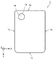
도 1은 본 발명의 일실시형태에 의한 편광자를 도시하는 개략 단면도이다.
도 2는 붕산 저농도 부위를 설명하기 위한 편광자의 개략 상면도이다.
도 3은 요오드 저농도 부위를 설명하기 위한 편광자의 개략 상면도이다.
도 4는 카메라 홀을 갖는 화상 표시 장치의 일례를 도시하는 개략 단면도이다.
도 5는 본 발명의 일실시형태에 의한 편광자를 도시하는 개략 상면도이다.
도 6은 본 발명의 일실시형태에 의한 편광판을 도시하는 개략 평면도이다.
도 7은 본 발명의 일실시형태에 의한 편광판을 도시하는 개략 평면도이다.
도 8은 본 발명의 일실시형태에 의한 편광판을 도시하는 개략 평면도이다.
도 9는 본 발명의 일실시형태에 의한 편광판을 도시하는 개략 단면도이다.
도 10은 제1 적층체의 일례를 도시하는 개략도이다.
도 11은 제2 적층체 및 엔드밀의 일례를 도시하는 개략도이다.
도 12는 절삭 공정의 일례를 도시하는 개략도이다.
도 13은 실시예에서의 측정 샘플을 설명하기 위한 개략도이다.
도 14는 실시예에서의 제1 적층체를 도시하는 개략 단면도이다.
도 15는 실시예에서의 편광판을 도시하는 개략 상면도이다.
도 16은 실시예 1의 TOF-SIMS 분석 결과 및 단부 관찰 결과를 도시한다.
도 17은 비교예 1의 TOF-SIMS 분석 결과 및 단부 관찰 결과를 도시한다.
도 18은 비교예 2의 TOF-SIMS 분석 결과 및 단부 관찰 결과를 도시한다. BRIEF DESCRIPTION OF THE DRAWINGS It is a schematic sectional drawing which shows the polarizer by one Embodiment of this invention.
2 is a schematic top view of a polarizer for explaining a boric acid low concentration site.
3 is a schematic top view of a polarizer for explaining a low iodine concentration site.
4 is a schematic cross-sectional view showing an example of an image display device having a camera hole.
It is a schematic top view which shows the polarizer by one Embodiment of this invention.
6 is a schematic plan view showing a polarizing plate according to an embodiment of the present invention.
7 is a schematic plan view showing a polarizing plate according to an embodiment of the present invention.
It is a schematic plan view which shows the polarizing plate by one Embodiment of this invention.
It is a schematic sectional drawing which shows the polarizing plate by one Embodiment of this invention.
It is a schematic diagram which shows an example of a 1st laminated body.
It is a schematic diagram which shows an example of a 2nd laminated body and an end mill.
12 is a schematic diagram illustrating an example of a cutting process.
It is a schematic diagram for demonstrating the measurement sample in an Example.
It is a schematic sectional drawing which shows the 1st laminated body in an Example.
It is a schematic top view which shows the polarizing plate in an Example.
16 shows the TOF-SIMS analysis result and the end observation result of Example 1. FIG.
17 shows a result of TOF-SIMS analysis and an end observation result of Comparative Example 1.
18 shows a result of TOF-SIMS analysis and an end observation result of Comparative Example 2.
이하, 도면을 참조하면서 본 발명의 실시형태를 설명하지만, 본 발명은 이하의 실시형태에 한정되는 것이 아니다. 이하의 모든 도면에서는, 각 구성요소를 이해하기 쉽게 하기 위해 축척을 적절하게 조정하여 나타내었고, 도면에 도시되는 각 구성요소의 축척과 실제의 구성요소의 축척은 반드시 일치하는 것은 아니다. 도면에 있어서, 동등한 구성요소에는 동등한 부호를 부여한다. 각 도면에 도시하는 X, Y 및 Z는, 서로 직교하는 3개의 좌표축을 의미한다. 각 도면 중의 XYZ 좌표축 각각이 나타내는 방향은 각 도면 공통이다. EMBODIMENT OF THE INVENTION Hereinafter, although embodiment of this invention is described, referring drawings, this invention is not limited to the following embodiment. In all the drawings below, the scales are appropriately adjusted for easy understanding of each component, and the scale of each component shown in the drawings does not necessarily coincide with the scale of the actual component. In the drawings, equal reference numerals are given to equal components. X, Y, and Z shown in each figure mean three coordinate axes orthogonal to each other. The directions indicated by each of the XYZ coordinate axes in each figure are common to each figure.
<편광자> <Polarizer>
편광자는, 붕산과 요오드를 함유하는 수지 필름이다. 붕산과 요오드를 함유하는 수지 필름은, 예컨대 일축 연신된 폴리비닐알코올계 수지 필름에 요오드가 흡착 배향되고, 폴리비닐알코올 분자쇄끼리 붕산으로 가교된 수지 필름일 수 있다. 편광자는, 흡수축에 평행한 진동면을 갖는 직선 편광을 흡수하고, 흡수축에 직교하는(투과축과 평행한) 진동면을 갖는 직선 편광을 투과하는 성질을 갖는 흡수형의 편광자일 수 있다. 편광자는, 한쪽 또는 양쪽에 광학 필름을 접착제 또는 점착제 등으로 접합하여 편광판으로서 이용할 수 있다. A polarizer is a resin film containing boric acid and an iodine. The resin film containing boric acid and iodine may be, for example, a resin film in which iodine is oriented by adsorption to a uniaxially stretched polyvinyl alcohol-based resin film, and polyvinyl alcohol molecular chains are crosslinked with boric acid. The polarizer may be an absorption type polarizer having a property of absorbing linearly polarized light having an oscillation plane parallel to the absorption axis and transmitting linearly polarized light having an oscillation plane perpendicular to the absorption axis (parallel to the transmission axis). A polarizer can be used as a polarizing plate by bonding an optical film to one or both sides with an adhesive agent, an adhesive, etc.
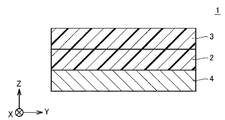
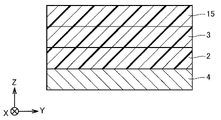
도 1에 도시하는 바와 같이, 편광자(2)는, 제1 광학 필름(3)과 제2 광학 필름(4)과의 사이에 배치되는 것에 의해 편광판(1)을 구성할 수 있다. 이하, 제1 광학 필름 및 제2 광학 필름을 총칭하여 광학 필름이라고 하는 경우가 있다. As shown in FIG. 1 , the
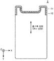
편광자는, 평면시에서의 단부를 포함하는 영역에 있어서, 단부로부터 500 μm 이상 내측의 내측 영역(이하, 내부 영역이라고도 함)에서의 붕산의 농도보다 낮은 붕산의 농도인 붕산 저농도 부위가 형성되어 있다. 내측 영역에 있어서, 붕산의 농도 및 요오드의 농도는 모두 거의 같을 수 있다. 도 2에 도시하는 바와 같이, 편광자(2)는, 평면시에서의 단부를 포함하는 영역에 있어서 붕산 저농도 부위(30)를 가지며, 단부로부터 500 μm 이상 내측에 내측 영역(32)을 가질 수 있다. 내측 영역(32)은, 액정 표시 장치에 삽입되었을 때에 화상을 표시하기 위한 영역을 포함할 수 있다. 붕산 저농도 부위(30)와 내부 영역(32) 사이의 중간 영역(31)에서의 붕산 농도는, 통상, 내측 영역(32)과 거의 동일한 붕산 농도이다. 본 명세서에서 평면시란, 편광자의 두께 방향에서 보는 것을 의미한다. 붕산의 농도는, 편광자의 두께 방향도 포함시킨 단위면적당 붕산의 농도를 말하며, 예컨대 후술하는 실시예의 란에서 설명하는 비행 시간형 이차 이온 질량 분석법(TOF-SIMS)에 의해 측정된다. 본 명세서에 있어서, 붕산에는, 예컨대 붕산 분자(H3BO3) 및 붕산 이온(BO3 3-)이 포함된다. In the polarizer, in the region including the end portion in plan view, a boric acid low concentration region having a lower boric acid concentration than the boric acid concentration in the inner region (hereinafter also referred to as an inner region) 500 μm or more inside the end portion is formed. . In the inner region, both the concentration of boric acid and the concentration of iodine may be approximately equal. As shown in Fig. 2, the
편광자는, 붕산 저농도 부위가 형성되어 있는 것에 의해, 결로 히트 쇼크 시험에 있어서 크랙의 발생이 억제되기 쉬워지는 경향이 있다. 결로 히트 쇼크 시험은, 후술하는 실시예의 란에 기재된 방법에 따라서 행할 수 있다. In a polarizer, generation|occurrence|production of a crack tends to become easy to be suppressed in a dew condensation heat shock test by the boric-acid low concentration site|part being formed. The condensation heat shock test can be performed according to the method described in the column of Examples to be described later.
붕산 저농도 부위에서의 붕산의 농도는, 크랙이 억제되고, 편광자의 외관에 있어서 색 빠짐이 눈에 띄기 어려워지는 관점에서, 바람직하게는 편광자의 평면시에서의 내측으로부터 단부로 향하는 방향에 있어서 단부에 가까울수록 낮아졌다. 편광자의 단부는 바람직하게는 붕산을 함유하지 않는다. The concentration of boric acid in the boric acid low concentration site is preferably at the end in the direction from the inside to the end in a planar view of the polarizer from the viewpoint of suppressing cracks and making color loss less conspicuous in the appearance of the polarizer. The closer it was, the lower it was. The ends of the polarizer preferably do not contain boric acid.
붕산 저농도 부위의 단부로부터의 길이는, 예컨대 15 μm 이상일 수 있고, 크랙 억제의 관점에서 바람직하게는 15 μm 이상 200 μm 미만, 보다 바람직하게는 15 μm 이상 150 μm 미만, 더욱 바람직하게는 15 μm 이상 100 μm 미만, 특히 바람직하게는 15 μm 이상 50 μm 미만일 수 있다. The length from the end of the boric acid low concentration site may be, for example, 15 µm or more, and from the viewpoint of crack suppression, preferably 15 µm or more and less than 200 µm, more preferably 15 µm or more and less than 150 µm, still more preferably 15 µm or more. It may be less than 100 μm, particularly preferably more than 15 μm and less than 50 μm.
붕산 저농도 부위가 형성된 영역과 그것 이외의 영역의 경계는, 후술하는 실시예의 란에서 설명하는 비행 시간형 이차 이온 질량 분석법(TOF-SIMS)에 있어서 얻어지는 단부로부터의 거리에 대한 붕산 농도 프로파일로부터 구할 수 있다. 예컨대, 붕산 농도 프로파일에 있어서 붕산 이온 강도가 일정한 영역이 판독되는 경우에는, 그 영역의 붕산 이온 강도의 평균치를 구하고, 단부로부터 붕산 이온 강도가 상기 평균치가 되는 위치까지를 붕산 저농도 부위로 할 수 있다. 상기 붕산 이온 강도가 일정한 영역이 붕산 농도 프로파일에 있어서 판독하기 어려운 경우에는, 붕산 농도 프로파일에 있어서, 붕산 이온 강도가 최대가 되는 점으로부터 내측에 30 μm의 범위에서의 붕산 이온 강도의 평균치를 구하고, 단부로부터 붕산 이온 강도가 상기 평균치가 되는 위치까지를 붕산 저농도 부위로 할 수 있다. The boundary between the region in which the boric acid low concentration region is formed and the region other than it can be obtained from the boric acid concentration profile with respect to the distance from the end obtained by the time-of-flight secondary ion mass spectrometry (TOF-SIMS) described in the section of Examples to be described later. there is. For example, when a region with a constant boric acid ion strength is read in the boric acid concentration profile, the average value of the boric acid ion strength of the region is obtained, and the region from the end to the position where the boric acid ion strength becomes the average value can be defined as the low boric acid concentration region. . If the region where the boric acid ion strength is constant is difficult to read in the boric acid concentration profile, in the boric acid concentration profile, the average value of the boric acid ion strength in the range of 30 μm is obtained from the point at which the boric acid ion strength is the maximum, The position from the edge part to the position where boric acid ion intensity|strength becomes the said average value can be made into a boric-acid low concentration site|part.
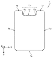
편광자는, 단부를 포함하는 영역에, 단부로부터 500 μm 이상 내측의 내측 영역에서의 요오드의 농도보다 낮은 요오드의 농도인 요오드 저농도 부위가 형성되어 있다. 요오드 저농도 부위의 단부로부터의 길이는 19 μm 이상 100 μm 이하이다. 도 3에 도시하는 바와 같이, 편광자(2)는, 평면시에서의 단부를 포함하는 영역에 있어서 요오드 저농도 부위(33)를 갖는다. 요오드 저농도 부위(33)와 내부 영역(32) 사이의 중간 영역(34)의 요오드 농도는 통상, 내측 영역(32)과 거의 동일한 요오드 농도이다. 요오드 저농도 부위는, 광학 현미경을 이용한 편광자의 평면시 관찰에 있어서 광이 투과하는 영역에 형성된 부위이다. 요오드에는, 예컨대 요오드 분자(I2), 폴리요오드 착체(I3 -, I5 -), 요오드 이온(I-)이 포함된다. In the polarizer, a low iodine concentration site having a lower iodine concentration than the iodine concentration in the inner region 500 µm or more inside the polarizer is formed in a region including the end portion. The length from the end of the low iodine concentration site is 19 µm or more and 100 µm or less. As shown in FIG. 3, the
요오드 저농도 부위의 단부로부터의 길이가 100 μm 이하인 경우, 편광자의 외관에 있어서 요오드 저농도부가 눈에 띄기 어려운 경향이 있다. 또한, 요오드 저농도 부위의 단부로부터의 길이가 19 μm 이상인 경우, 크랙이 억제되기 쉬워지는 경향이 있다. 요오드 저농도 부위의 단부로부터의 길이는, 요오드 손실이 눈에 띄기 어려워지는 관점에서 바람직하게는 19 μm 이상 50 μm 이하이다. When the length from the end of the low iodine concentration portion is 100 μm or less, the low iodine concentration portion tends to be difficult to be conspicuous in the external appearance of the polarizer. Moreover, when the length from the edge part of a low iodine concentration site|part is 19 micrometers or more, there exists a tendency for a crack to be suppressed easily. The length from the end of the low iodine concentration site is preferably 19 µm or more and 50 µm or less from the viewpoint of making the loss of iodine less conspicuous.
요오드 저농도 부위와 요오드 고농도 부위는, 후술하는 실시예의 란에서 설명하는 방법에 따라서 판별된다. 퍼스널 컴퓨터 상에 캡쳐하여 화상 처리한 광학 현미경 화상에 있어서, 요오드 저농도 부위의 밝기는 통상 180 이상이 되는 영역이 되고, 내측 영역은 100 이상 140 이하가 되고, 요오드 저농도 부위와 내부 영역 사이의 중간 영역의 요오드 농도의 밝기는 통상 180 미만이다. A site with a low iodine concentration and a site with a high iodine concentration are discriminated according to the method described in the section of Examples to be described later. In an optical microscope image captured and image-processed on a personal computer, the brightness of the low iodine concentration region is usually 180 or more, and the inner region is 100 or more and 140 or less, and an intermediate region between the low iodine concentration region and the inner region. The brightness of the iodine concentration is usually less than 180.
붕산 저농도 부위 및 요오드 저농도 부위는 서로 부분적으로 중복되는 부위일 수 있고, 또는 어느 한쪽이 다른쪽에 완전히 중복되는 부위일 수 있다. 크랙이 억제되고, 또한 요오드 손실이 눈에 띄기 어려워지는 관점에서, 바람직하게는 요오드 저농도 부위는 붕산 저농도 부위를 완전히 포함한다. The boric acid low concentration site and the low iodine concentration site may be a site partially overlapping with each other, or one may be a site completely overlapping the other. From the viewpoint of suppressing cracks and making iodine loss less conspicuous, preferably, the low iodine concentration site completely includes the boric acid low concentration site.
붕산 저농도 부위 및 요오드 저농도 부위는 각각, 편광자의 복수의 영역에 복수 형성되어 있어도 좋다. The boric acid low concentration site|part and the iodine low concentration site|part may each be formed in plurality in the some area|region of a polarizer.
붕산 저농도 부위 및 요오드 저농도 부위는, 크랙 억제의 관점에서 바람직하게는 편광자의 외연부를 따라 형성된다. 붕산 저농도 부위 및 요오드 저농도 부위는, 편광자의 외연부 전체를 따라 형성될 수 있고, 편광자의 외연부의 일부를 따라 형성되어도 좋다. The boric acid low concentration site|part and the low iodine concentration site|part are preferably formed along the outer edge of a polarizer from a viewpoint of crack suppression. The boric acid low concentration site|part and the iodine low concentration site|part may be formed along the whole outer edge part of a polarizer, and may be formed along a part of the outer edge part of a polarizer.
편광자는 이형부를 가질 수 있다. 이형부는, 편광자의 평면시에 있어서, 외연부에 형성된 오목형상부, 및 편광자 면내에 형성된 관통 구멍일 수 있다. 또한, 이형부는, 접선의 방향이 불연속으로 되어 있어, 예컨대 2개의 직선이 교차한 형상이며, 그 교점에서의 곡률반경이 0 mm이어도 좋다. 접선의 방향이 불연속으로 되어 있는 경우나, 교점에서의 곡률반경이 작은(통상 3 mm 이하, 바람직하게는 2 mm 이하, 더욱 바람직하게는 1 mm 이하) 경우에, 본 발명에 의한 크랙 방지의 효과가 현저하다. 편광자는, 외연부 및/또는 면내에 2 이상의 이형부를 가질 수 있다. 이형부의 형상 및 형성되는 위치의 구체예는, 후술하는 편광판의 설명에서의 이형부의 형상 및 형성되는 위치의 예시가 적용된다. The polarizer may have a deformable part. The release portion may be a concave portion formed on the outer edge portion of the polarizer in plan view, and a through hole formed in the surface of the polarizer. Moreover, the direction of the tangent line is discontinuous, for example, the shape of two straight lines intersecting the deformed part may be 0 mm at the intersection of the radius of curvature. The effect of preventing cracks according to the present invention when the direction of the tangent line is discontinuous or when the radius of curvature at the intersection is small (usually 3 mm or less, preferably 2 mm or less, more preferably 1 mm or less) is conspicuous The polarizer may have two or more deformable parts in an outer edge part and/or in-plane. As for the specific example of the shape and formation position of a mold part, the example of the shape and formation position of the mold part in the description of a polarizing plate mentioned later is applied.
편광자가 이형부를 갖는 경우, 크랙이 억제되고, 또한 요오드 저농도부가 눈에 띄기 어려워지는 관점에서 바람직하게는, 이형부에 포함되는 단부 영역에 있어서, 붕산 저농도 부위 및 요오드 저농도 부위가 형성되어 있다. When the polarizer has a release portion, cracks are suppressed and the low iodine concentration portion is preferably formed in the end region included in the mold release portion from the viewpoint of suppressing cracks and forming the low iodine concentration portion and the boric acid low concentration portion.
이형부를 갖는 편광자는, 결로 히트 쇼크 시험에 있어서, 이형부에 응력이 집중하기 쉽고, 크랙이 발생하기 쉬운 경향이 있다. 붕산 저농도 부위가 이형부에 포함되는 단부 영역에 있어서 형성되는 것에 의해, 결로 히트 쇼크 시험에 있어서 크랙의 발생이 억제되기 쉬워지는 경향이 있다. The polarizer which has a mold release part is a dew condensation heat shock test. WHEREIN: Stress tends to concentrate in a mold part part, and there exists a tendency for a crack to generate|occur|produce easily. When a boric-acid low concentration site|part is formed in the edge part area|region contained in a mold release part, there exists a tendency for generation|occurrence|production of a crack to become easy to suppress in a dew condensation heat shock test.
또한, 도 4에 도시하는 바와 같이, 이형부를 갖는 편광자를 구비한 편광판(21)이, 카메라 홀(22), 커버 유리(24), 점착제층(25), 액정 패널(23), 편광판(26), 카메라(27) 및 차광 테이프(28)를 갖는 화상 표시 장치(20)에 이용되는 경우, 도 4 중, 원으로 둘러싸인 부분은 직접 시인 가능하기 때문에, 편광자(21)의 이형부에 포함되는 단부에 있어서 넓은 영역에서 형성된 요오드 저농도 부위는 눈에 띄기 쉬워지고, 그 결과, 디자인성의 저하를 초래하는 경우가 있다. 그러나, 본 발명의 편광자는, 상기와 같은 카메라 홀을 갖는 화상 표시 장치에 이용하는 경우라 하더라도, 요오드 저농도 부위가 눈에 띄기 어려워, 디자인성이 우수한 경향이 있다. Moreover, as shown in FIG. 4, the
이형부가 오목형상부인 경우, 크랙 억제의 관점에서 바람직하게는, 오목형상부의 깊이 방향과 흡수축(연신 방향)은 예컨대 직교가 되도록 형성된다. 또한, 30도 이상 통상은 60도 이하의 각도로 교차하도록 형성되어도 좋다. When the deformable portion is a concave portion, it is preferably formed so that the depth direction of the concave portion and the absorption axis (stretching direction) are orthogonal to each other from the viewpoint of crack suppression, for example. Moreover, you may form so that it may intersect at an angle of 30 degrees or more and usually 60 degrees or less.
편광자는 장척의 띠형이어도 좋고, 매엽형이어도 좋다. 편광자가 매엽형인 경우, 편광자는 평면시에 있어서 전체 형상이 사각형 또는 라운딩된 사각형일 수 있다. 라운딩된 사각형이란, 사각형의 모서리부 중 하나 이상이 곡선으로 되어 있는 형상을 말하며, 즉 사각형의 모서리부 중 하나 이상이 라운딩되어 있고, 사각형이란 4개의 모서리가 모두 라운딩되지 않은 형상을 말하는 것으로 한다. 또한, 본 명세서에 있어서, 사각형이란 장방형 또는 정방형을 말하는 것으로 한다. 편광판이 라운딩된 사각형인 경우, 편광판이 갖는 4개의 모서리 중 하나 이상이 라운딩되어 있어도 좋다. 편광자는, 평면시에서의 전체 형상이 다각형, 원형 또는 타원형이어도 좋다. 편광자의 평면시에서의 전체 형상의 구체예는, 후술하는 편광판의 설명에서의 편광판의 전체 형상의 예시가 적용된다. A long strip|belt shape may be sufficient as a polarizer, and single-wafer type may be sufficient as it. When the polarizer is a single-wafer type, the polarizer may have a square shape or a rounded square shape in plan view. The rounded rectangle refers to a shape in which at least one of the corners of the rectangle is curved, that is, at least one of the corners of the rectangle is rounded, and the rectangle refers to a shape in which all four corners are not rounded. In addition, in this specification, a quadrangle shall mean a rectangle or a square. When the polarizing plate is a rounded rectangle, one or more of the four corners of the polarizing plate may be rounded. The polarizer may have a polygonal, circular, or elliptical overall shape in plan view. The example of the overall shape of a polarizing plate in description of the polarizing plate mentioned later is applied to the specific example of the overall shape in planar view of a polarizer.
편광자의 두께는, 예컨대 1 μm 이상 50 μm 이하일 수 있고, 3 μm 이상 15 μm 이하이어도 좋다. 편광자가 얇을수록, 온도 변화에 따르는 편광자 자체의 수축 또는 팽창이 억제되기 쉬워지고, 편광자 자체의 치수의 변화가 억제되기 쉬워지는 경향이 있다. 그 결과, 응력이 편광자에 작용하기 어려워지고, 편광자에서의 크랙이 억제되기 쉬워지는 경향이 있다. The thickness of the polarizer may be, for example, 1 µm or more and 50 µm or less, or 3 µm or more and 15 µm or less. As the polarizer is thinner, the shrinkage or expansion of the polarizer itself with a change in temperature tends to be suppressed, and the change in the dimension of the polarizer itself tends to be suppressed. As a result, stress becomes difficult to act on a polarizer, and there exists a tendency for the crack in a polarizer to become suppressed easily.
도 5는, 편광자(2)의 평면시에서의 전체 형상을 도시한다. 편광자(2)는, 전체 형상이 라운딩된 사각형이며, 이형부로서 오목형상부를 갖고 있다. 오목형상부는, 깊이 방향과 흡수축(연신 방향)이 평행해지도록 형성되어 있다. 편광자(2)에 있어서, 영역 I(11) 및 영역 II(12)가, 오목형상부를 포함하는 외주의 일부를 따라 부분적으로 형성되고, 오목형상부를 포함하는 외연부에 형성되어 있다. 영역 I(11)은, 붕산 저농도 부위 및 요오드 저농도 부위가 모두 형성된 영역이다. 영역 II(12)는, 붕산 저농도 부위 또는 요오드 저농도 부위의 어느 한쪽이 형성된 영역일 수 있다. FIG. 5 shows the overall shape of the
<편광판> <Polarizer>
본 발명의 다른 한 양태에 관한 편광판은, 전술한 편광자와, 그 한쪽 또는 양쪽에 형성된 광학 필름을 포함하는 편광판이다. 광학 필름은, 접착제 또는 점착제로 이루어진 접착층을 통해 편광자에 접합될 수 있다. The polarizing plate which concerns on another aspect of this invention is a polarizing plate containing the above-mentioned polarizer and the optical film formed in the one or both sides. The optical film may be bonded to the polarizer through an adhesive layer made of an adhesive or pressure-sensitive adhesive.
도 1에 도시된 바와 같이, 본 실시형태에 관한 편광판(1)은, 적어도 한쌍의 광학 필름(3, 4)과, 한쌍의 광학 필름(3, 4) 사이에 위치하는 필름형의 편광자(2)를 구비한다. 이하에서는, 설명의 편의상, 편광자(2)와 한쌍의 광학 필름(3, 4)으로 구성되는 편광판(1)이 주로 설명된다. 다만 후술하는 바와 같이, 편광판이 구비하는 광학 필름의 수는 2장에 한정되지 않는다. As shown in FIG. 1 , the
광학 필름은, 편광판(1)을 구성하는 필름형의 부재(편광자(2) 자체를 제외함)를 의미한다. 예컨대, 광학 필름은 보호 필름 및 이형 필름을 함의한다. 개개의 광학 필름은 단독으로 특정한 광학적 기능을 갖고 있지 않아도 좋다. 「필름」(광학 필름)은, 「층」(광학층)으로 환언해도 좋다. 한쌍의 광학 필름(3, 4) 각각은 수지를 포함한다. 다만, 광학 필름(3, 4) 각각의 조성은 한정되지 않는다. An optical film means the film-shaped member (excluding the
편광자(2)는, 광학 필름(3, 4) 각각과 직접적 또는 간접적으로 중복되어 있다. 예컨대, 편광자(2)와 광학 필름(3, 4) 사이에 별도의 광학 필름이 있을 수 있다. 편광자(2)가 접착층을 통해 광학 필름(3, 4) 각각과 중복되어 있어도 좋다. The
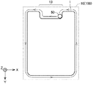
도 6은, 본 실시형태에 관한 편광판(1)의 표면을 도시하는 상면도이다. 도 6에 도시되는 편광판(1)의 단면은 편광판(1)의 표면에 수직이다. 또한, 이 편광판(1)의 단면은, 편광판(1)에 형성된 오목부(13)의 내측에 위치하는 편광판(1)의 외주(1p)와 직교한다. 6 : is a top view which shows the surface of the
도 6에 도시된 바와 같이, 오목부(13)가 편광판(1)의 외주(1p)에 형성되어 있다. 즉, 편광판(1)의 외주(1p)에는 오목부(13)가 있다. 오목부(13)는, 함몰부, 절결(cutоut) 또는 노치(nоtch)로 환언해도 좋다. 오목부(13)는, 편광판(1)의 표면(수광면)에 수직인 방향(Z축 방향)에 있어서 편광판(1)을 관통할 수 있다. 편광판(1)의 외주(1p)는, 편광판(1)의 수광면에 수직인 방향(평면시 방향)에서 보이는 편광판(1)(수광면)의 외연 또는 윤곽으로 환언해도 좋다. As shown in FIG. 6 , a
오목부(13) 내측의 모퉁이(13c)는, 상면시에서 직각으로 되어 있어도 좋고, 곡선으로 되어 있어도 좋다. 즉, 오목부(13) 내측의 모퉁이(13c)에 위치하는 편광판(1)의 단부면이 곡면일 수 있다. 즉, 오목부의 내측의 모퉁이(13c)가 면취(chamfer)될 수 있다. 오목부(13) 내측의 모퉁이(13c)가 상면시에서 곡선인 것에 의해, 직각으로 되어 있는 경우와 비교하여, 오목부(13) 내측의 모퉁이(13c)에서의 균열이 억제되기 쉽다. 도 4에 도시된 바와 같이, 오목부(13)의 양끝에 위치하는 모서리부 및 편광판(1)의 네 모퉁이에 위치하는 모서리부 각각도 면취될 수 있다. The
오목부(13)의 폭(X축 방향에서의 오목부(13)의 폭)은 특별히 한정되지 않지만, 예컨대 3 mm 이상 160 mm 이하일 수 있다. 오목부(13)의 깊이(Y축 방향에서의 오목부(13)의 폭)은 특별히 한정되지 않지만, 예컨대 0.5 mm 이상 160 mm 이하일 수 있다. 오목부(13)가 형성되어 있는 편광판(1)의 변(짧은 변)의 길이는 특별히 한정되지 않지만, 예컨대 30 mm 이상 90 mm 이하일 수 있다. 오목부(13)가 형성되어 있지 않은 편광판(1)의 변(긴 변)의 길이는 특별히 한정되지 않지만, 예컨대 30 mm 이상 170 mm 이하일 수 있다. The width of the concave portion 13 (the width of the
편광판(1) 전체의 두께는 특별히 한정되지 않지만, 예컨대 30 μm 이상 300 μm 이하일 수 있다. Although the thickness of the whole
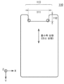
도 6에 도시되는 오목부(13)는 라운딩된 사각형(장방형)이다. 다만, 오목부(13)의 형상은 한정되지 않는다. 예컨대, 오목부(13)는 정방형이어도 좋다. 오목부(13)는 사각형 및 삼각형 이외의 다른 다각형이어도 좋다. 도 7 중의 (a)∼(h)에 도시하는 바와 같이, 오목부(13)의 형상은, 라운딩된 장방형, 장방형, 반원형, V자형, 직선과 곡선이 조합된 형상, 곡선형일 수 있다. 도 7 중의 (a)∼(h)에 도시되는 편광판(1)의 형상은 모두 대칭성을 갖고 있지만, 편광판(1)의 형상은 비대칭적이어도 좋다. 복수의 오목부(13)가 편광판(1)의 외주(1p)에 형성되어 있어도 좋다. 복수의 오목부(13)가, 편광판(1)의 외주(1p)를 구성하는 하나의 변에 형성되어도 좋다. 사각형의 편광판(1)의 4개의 모서리부 중 적어도 하나의 모서리부가 절결되는 것에 의해, 오목부(13)가 형성될 수 있다. The
오목부(13)를 제외한 편광판(1)의 전체적인 형상은, 거의 사각형(장방형)이다. 다만, 편광판(1)의 형상은 한정되지 않는다. 예를 들면, 편광판(1)의 형상은 정방형이어도 좋다. 편광판(1)의 형상은, 사각형 이외의 다각형, 원형 또는 타원형이어도 좋다. 편광자(2) 및 광학 필름(3, 4) 각각의 전체적인 형상은, 편광판(1)의 형상과 대략 동일할 수 있다. 도 4에 도시되는 장방형의 편광판(1)의 경우, 오목부(13)는 편광판(1)의 짧은 변에 형성되어 있지만, 오목부(13)는 편광판(1)의 긴 변에 형성되어 있어도 좋다. The overall shape of the
도 8에 도시하는 바와 같이, 편광자(1)는, 평면시에 있어서 면내에서 관통 구멍을 갖고 있어도 좋다. 관통 구멍의 직경은, 예컨대 0.5 mm 이상 30 mm 이하일 수 있고, 바람직하게는 1 mm 이상 10 mm 이하이다. As shown in FIG. 8, the
(편광판의 다른 실시형태)(Another embodiment of a polarizing plate)
예컨대, 편광판은, 제1 광학 필름 및 제2 광학 필름으로 이루어진 한쌍의 광학 필름에 더하여, 수지를 포함하는 별도의 광학 필름을 더 구비할 수 있다. 즉, 편광판은, 3장 이상의 광학 필름을 구비할 수 있다. 예컨대, 도 9에 도시된 바와 같이, 편광판이, 제1 광학 필름(3) 및 제2 광학 필름(4)과, 제1 광학 필름(3) 및 제2 광학 필름(4)의 사이에 위치하는 편광자(2)와, 제1 광학 필름(3)에 중복되는 제3 광학 필름(15)을 구비할 수 있다. 제3 광학 필름(15)은, 전술한 접착층을 통해 제1 광학 필름(3)에 중복될 수 있다. 제3 광학 필름(15)에 포함되는 수지는, 제1 광학 필름(3) 및 제2 광학 필름(4) 각각에 포함되는 수지로서 열거된 상기 수지 중 적어도 어느 하나일 수 있다. 제3 광학 필름(15)의 조성은, 제1 광학 필름(3)의 조성과 동일할 수 있다. 제3 광학 필름(15)의 조성은 제1 광학 필름(3)의 조성과 상이할 수 있다. 제3 광학 필름(15)의 조성은 제2 광학 필름(4)의 조성과 동일할 수 있다. 제3 광학 필름(15)의 조성은 제2 광학 필름(4)의 조성과 상이해도 좋다. 제3 광학 필름(15)의 두께는, 예컨대 5 μm 이상 200 μm 이하일 수 있다. 제3 광학 필름(15)은, 화상 표시 장치의 제조 과정에 있어서, 편광판으로부터 박리되어 제거될 수 있다. 즉, 제3 광학 필름(15)은 임시의 광학 필름일 수 있다. For example, the polarizing plate may further include a separate optical film including a resin in addition to a pair of optical films consisting of the first optical film and the second optical film. That is, a polarizing plate can be equipped with 3 or more optical films. For example, as shown in FIG. 9 , the polarizing plate is positioned between the first
편광판은, 한쌍의 광학 필름 중 한쪽에 중복되는 점착층과, 점착층에 중복되는 이형 필름을 더 구비할 수 있다. 예컨대, 도 9에 도시되는 편광판은, 제2 광학 필름(4)에 중복되는 점착층과, 점착층에 중복되는 이형 필름을 더 구비할 수 있다. 점착층은, 예컨대, 아크릴계 감압형 접착제, 고무계 감압형 접착제, 실리콘계 감압형 접착제 또는 우레탄계 감압형 접착제 등의 감압형 접착제를 포함할 수 있다. 점착층의 두께는, 예컨대 2 μm 이상 100 μm 이하일 수 있다. 이형 필름에 포함되는 수지는, 제1 광학 필름(3) 및 제2 광학 필름(4) 각각에 포함되는 수지로서 열거된 상기 수지 중 적어도 어느 하나일 수 있다. 이형 필름의 조성은 제1 광학 필름(3)의 조성과 동일할 수 있다. 이형 필름의 조성은 제1 광학 필름(3)의 조성과 상이해도 좋다. 이형 필름의 조성은 제2 광학 필름(4)의 조성과 동일할 수 있다. 이형 필름의 조성은 제2 광학 필름(4)의 조성과 상이해도 좋다. 이형 필름의 두께는, 예컨대 10 μm 이상 100 μm 이하일 수 있다. 이형 필름은, 화상 표시 장치의 제조 과정에 있어서, 편광판으로부터 박리되어 제거될 수 있다. 이형 필름이 점착층을 통해 편광판의 양면에 배치되어 있어도 좋다. The polarizing plate may further include a pressure-sensitive adhesive layer overlapping one of the pair of optical films, and a release film overlapping the pressure-sensitive adhesive layer. For example, the polarizing plate shown in FIG. 9 may further include a pressure-sensitive adhesive layer overlapping the second
편광판은, 광학 필름 또는 층으로서, 반사형 편광 필름, 방현 기능이 있는 필름, 표면 반사 방지 기능이 있는 필름, 반사 필름, 반투과 반사 필름, 시야각 보상 필름, 윈도우 필름, 대전 방지층, 하드코트층, 광학 보상층, 터치 센서층 및 방오층으로 이루어진 군에서 선택되는 적어도 1종을 더 구비할 수 있다. A polarizing plate, as an optical film or layer, is a reflective polarizing film, a film with an anti-glare function, a film with a surface antireflection function, a reflective film, a transflective film, a viewing angle compensation film, a window film, an antistatic layer, a hard coat layer, At least one selected from the group consisting of an optical compensation layer, a touch sensor layer, and an antifouling layer may be further provided.
편광판은, 평면시에 있어서 이형부를 가질 수 있다. 또한, 편광판은, 평면시에 있어서 사각형 또는 라운딩된 사각형일 수 있다. A polarizing plate can have a mold release part in planar view. In addition, the polarizing plate may be a quadrangle or a rounded quadrangle in plan view.
(광학 필름)(optical film)
광학 필름은, 투과성을 갖는 열가소성 수지일 수 있다. 광학 필름은, 광학적으로 투명한 열가소성 수지이어도 좋다. 광학 필름을 구성하는 수지는, 예컨대, 쇄형 폴리올레핀계 수지, 고리형 올레핀 폴리머계 수지(COP계 수지), 셀룰로오스에스테르계 수지, 폴리에스테르계 수지, 폴리카보네이트계 수지, (메트)아크릴계 수지, 폴리스티렌계 수지, 또는 이들의 혼합물 혹은 공중합체일 수 있다. The optical film may be a thermoplastic resin having transparency. The optical film may be an optically transparent thermoplastic resin. The resin constituting the optical film is, for example, a chain polyolefin-based resin, a cyclic olefin polymer-based resin (COP-based resin), a cellulose ester-based resin, a polyester-based resin, a polycarbonate-based resin, a (meth)acrylic resin, and a polystyrene-based resin. resin, or a mixture or copolymer thereof.
편광판이 제1 광학 필름과 제2 광학 필름을 갖는 경우, 제1 광학 필름의 조성은 제2 광학 필름의 조성과 완전히 동일할 수 있다. 예컨대, 제1 광학 필름 및 제2 광학 필름이 모두 고리형 올레핀 폴리머계 수지(COP계 수지)를 포함할 수 있다. 제1 광학 필름 및 제2 광학 필름이 고리형 올레핀 폴리머계 수지(COP계 수지)를 포함하는 경우라 하더라도, 본 발명에서는 크랙이 억제되기 쉽고, 색 빠짐이 눈에 띄지 않게 되기 쉽다. 편광판이 제1 광학 필름과 제2 광학 필름을 갖는 경우, 제1 광학 필름의 조성은 제2 광학 필름의 조성과 상이해도 좋다. When the polarizing plate has the first optical film and the second optical film, the composition of the first optical film may be exactly the same as that of the second optical film. For example, both the first optical film and the second optical film may include a cyclic olefin polymer-based resin (COP-based resin). Even when the first optical film and the second optical film contain a cyclic olefin polymer-based resin (COP-based resin), cracks are easily suppressed in the present invention, and color loss tends to become inconspicuous. When a polarizing plate has a 1st optical film and a 2nd optical film, the composition of a 1st optical film may differ from a composition of a 2nd optical film.
제1 광학 필름 및 제2 광학 필름의 유리 전이 온도는, 100℃ 이상 200℃이하, 또는 120℃ 이상 150℃ 이하인 것이 바람직하다. 제1 광학 필름 및 제2 광학 필름 각각의 유리 전이 온도가 상기 범위인 경우, 각 광학 필름의 단부의 연마에 의해 발생하는 열에 의해, 제1 광학 필름 및 제2 광학 필름이 서로 융착하기 쉽다. It is preferable that the glass transition temperatures of a 1st optical film and a 2nd optical film are 100 degrees C or more and 200 degrees C or less, or 120 degrees C or more and 150 degrees C or less. When the glass transition temperature of each of the first optical film and the second optical film is within the above range, the first optical film and the second optical film are likely to be fused to each other by heat generated by polishing of the end of each optical film.
쇄형 폴리올레핀계 수지는, 예컨대, 폴리에틸렌 수지 또는 폴리프로필렌 수지와 같은 쇄형 올레핀의 단독 중합체일 수 있다. 쇄형 폴리올레핀계 수지는, 2종이상의 쇄형 올레핀으로 이루어진 공중합체이어도 좋다. The chain-type polyolefin-based resin may be, for example, a homopolymer of a chain-type olefin such as a polyethylene resin or a polypropylene resin. The chain polyolefin resin may be a copolymer composed of two or more chain olefins.
고리형 올레핀 폴리머계 수지(고리형 폴리올레핀계 수지)는, 예컨대, 고리형 올레핀의 개환 (공)중합체, 또는 고리형 올레핀의 부가 중합체일 수 있다. 고리형 올레핀 폴리머계 수지는, 예컨대, 고리형 올레핀과 쇄형 올레핀의 공중합체(예컨대 랜덤 공중합체)일 수 있다. 공중합체를 구성하는 쇄형 올레핀은, 예컨대, 에틸렌 또는 프로필렌일 수 있다. 고리형 올레핀 폴리머계 수지는, 상기 중합체를 불포화 카르복실산 혹은 그 유도체로 변성한 그래프트 중합체, 또는 이들의 수소화물이어도 좋다. 고리형 올레핀 폴리머계 수지는, 예컨대, 노르보넨 또는 다환 노르보넨계 모노머 등의 노르보넨계 모노머를 이용한 노르보넨계 수지일 수 있다. The cyclic olefin polymer-based resin (cyclic polyolefin-based resin) may be, for example, a ring-opened (co)polymer of a cyclic olefin or an addition polymer of a cyclic olefin. The cyclic olefin polymer-based resin may be, for example, a copolymer (eg, a random copolymer) of a cyclic olefin and a chain olefin. The chain olefin constituting the copolymer may be, for example, ethylene or propylene. The cyclic olefin polymer resin may be a graft polymer obtained by modifying the polymer with an unsaturated carboxylic acid or a derivative thereof, or a hydride thereof. The cyclic olefin polymer-based resin may be, for example, a norbornene-based resin using a norbornene-based monomer such as norbornene or a polycyclic norbornene-based monomer.
셀룰로오스에스테르계 수지는, 예컨대, 셀룰로오스트리아세테이트(트리아세틸셀룰로오스(TAC)), 셀룰로오스디아세테이트, 셀룰로오스트리프로피오네이트 또는 셀룰로오스디프로피오네이트일 수 있다. 이들의 공중합물을 이용해도 좋다. 수산기의 일부가 다른 치환기로 수식된 셀룰로오스에스테르계 수지를 이용해도 좋다. The cellulose ester-based resin may be, for example, cellulose triacetate (triacetyl cellulose (TAC)), cellulose diacetate, cellulose tripropionate or cellulose dipropionate. You may use these copolymers. You may use the cellulose ester-type resin by which a part of hydroxyl group was modified by the other substituent.
셀룰로오스에스테르계 수지 이외의 폴리에스테르계 수지를 이용해도 좋다. 폴리에스테르계 수지는, 예컨대, 다가 카르복실산 또는 그 유도체와 다가 알코올과의 중축합체일 수 있다. 다가 카르복실산 또는 그 유도체는, 디카르복실산 또는 그 유도체일 수 있다. 다가 카르복실산 또는 그 유도체는, 예컨대, 테레프탈산, 이소프탈산, 디메틸테레프탈레이트, 또는 나프탈렌디카르복실산디메틸일 수 있다. 다가 알코올은, 예컨대 디올일 수 있다. 다가 알코올은, 예컨대, 에틸렌글리콜, 프로판디올, 부탄디올, 네오펜틸글리콜 또는 시클로헥산디메탄올일 수 있다. You may use polyester-type resin other than cellulose-ester-type resin. The polyester-based resin may be, for example, a polycondensate of a polyhydric carboxylic acid or a derivative thereof and a polyhydric alcohol. Polyhydric carboxylic acid or its derivative(s) may be dicarboxylic acid or its derivative(s). The polyhydric carboxylic acid or its derivative may be, for example, terephthalic acid, isophthalic acid, dimethyl terephthalate, or dimethyl naphthalenedicarboxylic acid. The polyhydric alcohol may be, for example, a diol. The polyhydric alcohol may be, for example, ethylene glycol, propanediol, butanediol, neopentyl glycol or cyclohexanedimethanol.
폴리에스테르계 수지는, 예컨대, 폴리에틸렌테레프탈레이트, 폴리부틸렌테레프탈레이트, 폴리에틸렌나프탈레이트, 폴리부틸렌나프탈레이트, 폴리트리메틸렌테레프탈레이트, 폴리트리메틸렌나프탈레이트, 폴리시클로헥산디메틸테레프탈레이트, 또는 폴리시클로헥산디메틸나프탈레이트일 수 있다. The polyester-based resin is, for example, polyethylene terephthalate, polybutylene terephthalate, polyethylene naphthalate, polybutylene naphthalate, polytrimethylene terephthalate, polytrimethylene naphthalate, polycyclohexanedimethyl terephthalate, or polycyclohexane. It may be dimethyl naphthalate.
폴리카보네이트계 수지는, 카보네이트를 통해 중합 단위(모노머)가 결합된 중합체이다. 폴리카보네이트계 수지는, 수식된 폴리머 골격을 갖는 변성 폴리카보네이트일 수 있고, 공중합 폴리카보네이트이어도 좋다. The polycarbonate-based resin is a polymer in which a polymerization unit (monomer) is bonded through a carbonate. The polycarbonate-based resin may be a modified polycarbonate having a modified polymer skeleton, or may be a copolymerized polycarbonate.
(메트)아크릴계 수지는, 예컨대, 폴리(메트)아크릴산에스테르(예컨대, 폴리메타크릴산메틸(PMMA)); 메타크릴산메틸-(메트)아크릴산 공중합체; 메타크릴산메틸-(메트)아크릴산에스테르 공중합체; 메타크릴산메틸-아크릴산에스테르-(메트)아크릴산 공중합체; (메트)아크릴산메틸-스티렌 공중합체(예컨대, MS 수지); 메타크릴산메틸과 지환족 탄화수소기를 갖는 화합물과의 공중합체(예컨대, 메타크릴산메틸-메타크릴산시클로헥실 공중합체, 메타크릴산메틸-(메트)아크릴산노르보닐 공중합체 등)일 수 있다. The (meth)acrylic resin is, for example, poly(meth)acrylic acid ester (eg, polymethyl methacrylate (PMMA)); methyl methacrylate-(meth)acrylic acid copolymer; methyl methacrylate-(meth)acrylic acid ester copolymer; methyl methacrylate-acrylic acid ester-(meth)acrylic acid copolymer; (meth) methyl acrylate-styrene copolymer (eg, MS resin); It may be a copolymer of methyl methacrylate and a compound having an alicyclic hydrocarbon group (eg, methyl methacrylate-cyclohexyl methacrylate copolymer, methyl methacrylate-(meth) acrylate norbornyl copolymer, etc.).
제1 광학 필름 또는 제2 광학 필름 각각은, 윤활제, 가소제, 분산제, 열안정제, 자외선 흡수제, 적외선 흡수제, 대전 방지제 및 산화 방지제로 이루어진 군에서 선택되는 적어도 1종의 첨가제를 포함할 수 있다. Each of the first optical film or the second optical film may include at least one additive selected from the group consisting of a lubricant, a plasticizer, a dispersant, a heat stabilizer, an ultraviolet absorber, an infrared absorber, an antistatic agent, and an antioxidant.
제1 광학 필름의 두께는, 예컨대, 5 μm 이상 90 μm 이하, 또는 10 μm 이상 60 μm 이하일 수 있다. 제2 광학 필름의 두께도, 예컨대, 5 μm 이상 90 μm 이하, 또는 10 μm 이상 60 μm 이하일 수 있다. The thickness of the first optical film may be, for example, 5 μm or more and 90 μm or less, or 10 μm or more and 60 μm or less. The thickness of the second optical film may also be, for example, 5 μm or more and 90 μm or less, or 10 μm or more and 60 μm or less.
제1 광학 필름 및 제2 광학 필름 중 적어도 한쪽은 광학 기능을 갖는 필름일 수 있다. 광학 기능을 갖는 필름이란, 예컨대, 위상차 필름 또는 휘도 향상 필름일 수 있다. 예컨대, 상기 열가소성 수지로 이루어진 필름을 연신하거나, 그 필름 상에 액정층 등을 형성하거나 하는 것에 의해, 임의의 위상차치가 부여된 위상차 필름이 얻어진다. At least one of the first optical film and the second optical film may be a film having an optical function. The film having an optical function may be, for example, a retardation film or a brightness enhancing film. For example, the retardation film to which arbitrary retardation values were provided is obtained by extending|stretching the film which consists of the said thermoplastic resin, or forming a liquid-crystal layer etc. on the film.
제1 광학 필름은 접착층을 통해 편광자에 중복될 수 있다. 제2 광학 필름도 접착층을 통해 편광자에 중복될 수 있다. 접착층은 폴리비닐알코올 등의 수계접착제를 포함할 수 있다. 접착층은 후술하는 활성 에너지선 경화성 수지를 포함해도 좋다. The first optical film may overlap the polarizer through an adhesive layer. The second optical film may also be overlapped with the polarizer through the adhesive layer. The adhesive layer may include a water-based adhesive such as polyvinyl alcohol. The adhesive layer may also contain the active energy ray-curable resin mentioned later.
활성 에너지선 경화성 수지는, 활성 에너지선이 조사되는 것에 의해 경화하는 수지이다. 활성 에너지선은, 예컨대, 자외선, 가시광, 전자선 또는 X선일 수 있다. 예컨대, 활성 에너지선 경화성 수지는 자외선 경화성 수지일 수 있다. Active energy ray-curable resin is resin which hardens|cures when an active energy ray is irradiated. The active energy ray may be, for example, ultraviolet light, visible light, electron beam or X-ray. For example, the active energy ray-curable resin may be an ultraviolet-curable resin.
활성 에너지선 경화성 수지는, 1종의 수지일 수 있고, 복수종의 수지를 포함해도 좋다. 예컨대, 활성 에너지선 경화성 수지는, 양이온 중합성의 경화성 화합물, 또는 라디칼 중합성의 경화성 화합물을 포함할 수 있다. 활성 에너지선 경화성 수지는, 상기 경화성 화합물의 경화 반응을 시작시키기 위한 양이온 중합 개시제 또는 라디칼 중합 개시제를 포함할 수 있다. Active energy ray-curable resin may be 1 type of resin, and may also contain multiple types of resin. For example, active energy ray-curable resin can contain a cationically polymerizable sclerosing|hardenable compound, or a radically polymerizable sclerosing|hardenable compound. The active energy ray-curable resin may include a cationic polymerization initiator or a radical polymerization initiator for initiating a curing reaction of the curable compound.
양이온 중합성의 경화성 화합물은, 예컨대, 에폭시계 화합물(분자 내에 적어도 하나의 에폭시기를 갖는 화합물), 또는 옥세탄계 화합물(분자 내에 적어도 하나의 옥세탄 고리를 갖는 화합물)일 수 있다. 라디칼 중합성의 경화성 화합물은, 예컨대, (메트)아크릴계 화합물(분자 내에 적어도 하나의 (메트)아크릴로일옥시기를 갖는 화합물)일 수 있다. 라디칼 중합성의 경화성 화합물은, 라디칼 중합성의 이중 결합을 갖는 비닐계 화합물이어도 좋다. The cationically polymerizable curable compound may be, for example, an epoxy-based compound (a compound having at least one epoxy group in its molecule) or an oxetane-based compound (a compound having at least one oxetane ring in its molecule). The radical polymerizable curable compound may be, for example, a (meth)acrylic compound (a compound having at least one (meth)acryloyloxy group in the molecule). The radically polymerizable sclerosing|hardenable compound may be a vinyl-type compound which has a radically polymerizable double bond.
활성 에너지선 경화성 수지는, 필요에 따라서, 양이온 중합 촉진제, 이온 트랩제, 산화 방지제, 연쇄 이동제, 점착 부여제, 열가소성 수지, 충전제, 유동 조정제, 가소제, 소포제, 대전 방지제, 레벨링제 또는 용제 등을 포함할 수 있다. The active energy ray-curable resin may optionally contain a cationic polymerization accelerator, an ion trapping agent, an antioxidant, a chain transfer agent, a tackifier, a thermoplastic resin, a filler, a flow regulator, a plasticizer, an antifoaming agent, an antistatic agent, a leveling agent or a solvent. may include
편광자와 광학 필름의 접착성을 향상시키기 위해, 편광자와 광학 필름의 접합에 앞서, 편광자 및/또는 광학 필름의 접합면에, 코로나 처리, 화염 처리, 플라즈마 처리, 자외선 조사 처리, 프라이머 도포 처리, 비누화 처리 등의 표면 처리를 해도 좋다. In order to improve the adhesiveness of a polarizer and an optical film, prior to bonding of a polarizer and an optical film, on the bonding surface of a polarizer and/or an optical film, corona treatment, flame treatment, plasma treatment, ultraviolet irradiation treatment, primer coating treatment, saponification You may perform surface treatment, such as a treatment.
(그 밖의 층)(Other floors)
편광판은, 전면판, 위상차 필름(예컨대 λ/2의 위상차를 부여하는 층, λ/4의 위상차를 부여하는 층, 포지티브 C층 및 이들에서 선택되는 적어도 2개의 층의 조합을 적층하여 얻어지는 층 등), 프로텍트 필름, 터치센서 패널, 점착제층 등을 더 구비하고 있어도 좋다. 편광판은, λ/4의 위상차를 부여하는 층을 적층하는 것에 의해 원편광판으로서 이용할 수도 있다. 편광판은 점착제층이 있는 편광판이어도 좋다. A polarizing plate is a front plate, a retardation film (for example, a layer imparting a retardation of λ/2, a layer imparting a retardation of λ/4, a positive C layer, a layer obtained by laminating a combination of at least two layers selected from these, etc. ), a protection film, a touch sensor panel, an adhesive layer, etc. may be further provided. A polarizing plate can also be used as a circularly polarizing plate by laminating|stacking the layer which provides the phase difference of (lambda)/4. A polarizing plate with an adhesive layer may be sufficient as a polarizing plate.
<편광판의 제조 방법> <Method for producing a polarizing plate>
편광판의 제조 방법은, 붕산과 요오드를 함유하는 수지 필름인 편광자와, 이 편광자의 한쪽 또는 양쪽에 배치된 광학 필름을 갖는 편광판의 제조 방법으로서, 붕산과 요오드를 함유하는 수지 필름의 단부에, 50℃ 이하의 온도의 염기성 용액을 6분 이내의 시간으로 접촉시키는 염기 처리 공정을 포함하는 제조 방법이다. 이 편광판의 제조 방법은, 이 염기 처리 공정의 전에, 후술하는 편광자 제조 공정(붕산과 요오드를 함유하는 수지 필름의 제조 공정), 적층 공정, 성형 공정 및 절삭 공정을 이 순으로 더 포함할 수 있다. The manufacturing method of a polarizing plate is a manufacturing method of a polarizing plate which has a polarizer which is a resin film containing boric acid and iodine, and the optical film arrange|positioned on one or both sides of this polarizer, At the edge part of the resin film containing boric acid and iodine, 50 It is a manufacturing method comprising a base treatment step of contacting a basic solution having a temperature of ℃ or less in 6 minutes or less. The manufacturing method of this polarizing plate may further include the polarizer manufacturing process mentioned later (manufacturing process of a resin film containing boric acid and iodine), a lamination process, a shaping|molding process, and a cutting process in this order before this base treatment process. .
(편광자 제조 공정)(Polarizer manufacturing process)
붕산과 요오드를 함유하는 수지 필름(이하, 미염기 처리 편광자라고도 함)은, 예컨대 폴리비닐알코올계 수지 필름(PVA 필름)에 연신 처리, 염색 처리 및 가교 처리를 하는 것에 의해 제조할 수 있다. 연신 처리, 염색 처리 및 가교 처리는 공지의 방법에 의해 행할 수 있다. A resin film containing boric acid and iodine (hereinafter also referred to as a light base treated polarizer) can be produced, for example, by subjecting a polyvinyl alcohol-based resin film (PVA film) to a stretching treatment, a dyeing treatment, and a crosslinking treatment. The stretching treatment, the dyeing treatment and the crosslinking treatment can be performed by a known method.
예컨대, 우선, PVA 필름을 일축 방향 또는 이축 방향으로 연신한다. 일축 방향으로 연신된 편광자의 2색비는 높은 경향이 있다. 연신에 이어서, 염색액을 이용하여 PVA 필름을 요오드, 2색성 색소(폴리요오드) 또는 유기 염료에 의해 염색한다. 염색액은, 붕산, 황산아연 또는 염화아연을 포함하고 있어도 좋다. 염색전에 PVA 필름을 수세해도 좋다. 수세에 의해, PVA 필름의 표면으로부터 오염 및 블로킹 방지제가 제거된다. 또한 수세에 의해 PVA 필름이 팽윤한 결과, 염색의 얼룩(불균일한 염색)이 억제되기 쉽다. 염색후의 PVA 필름을, 가교를 위해, 붕산을 포함하는 가교제의 용액(예컨대 붕산의 수용액)으로 처리한다. 가교제에 의한 처리후, PVA 필름을 수세하고, 이어서 건조시킨다. 이상의 순서를 거쳐, 붕산과 요오드를 함유하는 수지 필름이 얻어진다. For example, first, a PVA film is stretched in a uniaxial direction or a biaxial direction. The dichroic ratio of the polarizer stretched in the uniaxial direction tends to be high. After stretching, the PVA film is dyed with iodine, a dichroic dye (polyiodine) or an organic dye using a dyeing solution. The dyeing solution may contain boric acid, zinc sulfate, or zinc chloride. You may wash the PVA film with water before dyeing. By washing with water, stains and antiblocking agents are removed from the surface of the PVA film. Moreover, as a result of the swelling of a PVA film by water washing, it is easy to suppress the unevenness of dyeing (non-uniform dyeing|dyeing). The PVA film after dyeing is treated with a solution of a crosslinking agent containing boric acid (eg, an aqueous solution of boric acid) for crosslinking. After treatment with the crosslinking agent, the PVA film is washed with water and then dried. Through the above procedures, a resin film containing boric acid and iodine is obtained.
폴리비닐알코올(PVA)계 수지는, 폴리아세트산비닐계 수지를 비누화하는 것에 의해 얻어진다. 폴리아세트산비닐계 수지는, 예컨대, 아세트산비닐의 단독 중합체인 폴리아세트산비닐, 또는 아세트산비닐과 다른 단량체와의 공중합체(예컨대, 에틸렌-아세트산비닐 공중합체)일 수 있다. 아세트산비닐과 공중합하는 다른 단량체는, 에틸렌 외에, 불포화 카르복실산류, 올레핀류, 비닐에테르류, 불포화 술폰산류, 또는 암모늄기를 갖는 아크릴아미드류일 수 있다. 폴리비닐알코올계 수지는 알데히드류로 변성되어 있어도 좋다. 변성된 폴리비닐알코올계 수지는, 예컨대, 부분 포르말화폴리비닐알코올, 폴리비닐아세탈 또는 폴리비닐부티랄일 수 있다. 폴리비닐알코올계 수지는, 폴리비닐알코올의 탈수 처리물, 또는 폴리염화비닐의 탈염산 처리물 등의 폴리엔계 배향 필름일 수 있다. 연신전에 염색을 행해도 좋고, 염색액 중에서 연신을 행해도 좋다. 연신된 수지 필름의 길이는, 예컨대, 연신전의 길이의 3∼7배일 수 있다. 폴리비닐알코올계 수지 필름은, 장척의 띠형이어도 좋고, 매엽형이어도 좋다. Polyvinyl alcohol (PVA)-type resin is obtained by saponifying polyvinyl acetate-type resin. The polyvinyl acetate-based resin may be, for example, polyvinyl acetate, which is a homopolymer of vinyl acetate, or a copolymer of vinyl acetate and other monomers (eg, ethylene-vinyl acetate copolymer). Other monomers copolymerized with vinyl acetate may be unsaturated carboxylic acids, olefins, vinyl ethers, unsaturated sulfonic acids, or acrylamides having an ammonium group in addition to ethylene. The polyvinyl alcohol-based resin may be modified with aldehydes. The modified polyvinyl alcohol-based resin may be, for example, partially formalized polyvinyl alcohol, polyvinyl acetal or polyvinyl butyral. The polyvinyl alcohol-based resin may be a polyene-based oriented film such as a dehydrated product of polyvinyl alcohol or a dehydrochlorinated product of polyvinyl chloride. You may dye|stain before extending|stretching, and you may extend|stretch in a dyeing solution. The length of the stretched resin film may be, for example, 3 to 7 times the length before stretching. A long strip|belt shape may be sufficient as a polyvinyl alcohol-type resin film, and single-wafer type may be sufficient as it.
(적층 공정)(Lamination process)
적층 공정에서는, 미염기 처리 편광자와 광학 필름을 중복하여 서로 접합함으로써 제1 적층체를 제작한다. 미염기 처리 편광자 및 광학 필름은, 장척의 띠형일 수 있다. 미염기 처리 편광자를, 한쌍의 광학 필름 사이에 배치되도록 중복하는 경우, 도 10에 도시된 바와 같이, 제1 적층체(10)에 있어서, 미염기 처리 편광자(7)는 한쌍의 광학 필름(5, 9) 사이에 위치한다. At a lamination|stacking process, a 1st laminated body is produced by overlapping a slight base treatment polarizer and an optical film and bonding together. The light base treatment polarizer and the optical film may be in the shape of a long strip. In the case of overlapping the polarizer with a base treatment so as to be disposed between a pair of optical films, as shown in FIG. 10 , in the
광학 필름은 접착층을 통해 편광자에 접합할 수 있다. The optical film may be bonded to the polarizer through an adhesive layer.
적층 공정에 있어서, 제1 적층체(10)의 어느 한쪽의 최외면에 점착제층을 형성할 수 있다. 점착제층은, 예컨대 한쌍의 광학 필름(5, 9)의 어느 한쪽의 미염기 처리 편광자(7)와는 반대측의 면에 점착제를 도포하여 점착제층을 형성하고, 그 위에 점착제층으로부터 박리 가능한 세퍼레이트 필름을 접합하는 것에 의해 형성할 수 있다. 또한, 적층 공정에 있어서, 제1 적층체(10)의 어느 한쪽의 최외면에, 광학 필름으로부터 박리 가능한 프로텍트 필름을 접합할 수 있다. Lamination process WHEREIN: An adhesive layer can be formed in any one outermost surface of the 1st
(성형 공정)(Forming process)
성형 공정에 있어서, 제1 적층체(10)는, 제1 적층체(10)의 치수가 가공하기 쉬운 치수로 조정될 수 있다. 또한, 펀칭 가공 또는 절단 가공에 의해, 제1 적층체(10)의 외연부에 이형부를 형성해도 좋다. 절단 및/또는 펀칭 가공은, 절단날을 이용하거나, 펀칭날을 이용하거나, 레이저광을 조사하거나 하는 것에 의해 행할 수 있다. 레이저광은 CO2 레이저일 수 있다. 장척형의 제1 적층체를 성형 공정에 있어서 매엽형의 제1 적층체로 할 수 있다. In a molding process, the 1st
성형 공정에 있어서, 제1 적층체는, 단독으로 또는 복수장 중복한 상태로 절단 가공이나 펀칭 가공을 행할 수 있다. A shaping|molding process WHEREIN: A 1st laminated body can perform a cutting process or a punching process individually or in the state which overlapped two or more.
(절삭 공정)(cutting process)
편광판의 제조 방법은, 엔드밀을 제1 적층체 또는 후술하는 제2 적층체의 외주에 접촉시켜, 엔드밀을 적층체의 외주를 따라 이동시키는 절삭 공정을 더 포함할 수 있다. 도 10에 도시된 바와 같이, 절삭 공정전의 제1 적층체(10)의 외주 전역에 있어서, 미염기 처리 편광자(7) 및 광학 필름(5, 9) 각각의 단부의 위치는 일치할수 있다. The manufacturing method of the polarizing plate may further include a cutting step of bringing the end mill into contact with the outer periphery of the first laminate or the second laminate to be described later, and moving the end mill along the outer periphery of the laminate. As shown in FIG. 10 , in the entire outer periphery of the
도 11 및 도 12에 도시된 바와 같이, 절삭 공정에 이용되는 엔드밀(50)은, 그 회전축선(50a)에 대략 평행한 측면에 있어서 돌출된 날(엣지)(50e)을 갖고 있다. 절삭 공정에서는, 엔드밀(50)의 측면을 제1 적층체(10)의 외주(단부면)에 접촉시켜, 회전하는 엔드밀(50)을 제1 적층체(10)의 외주를 따라 이동시킨다. 예컨대, 회전하는 엔드밀(50)을 도 12 중의 화살표로 나타낸 경로를 따라 이동시킬 수 있다. 그 결과, 제1 적층체(10)의 외주(단부면)가 날(50e)에 의해 절삭 또는 연마되어, 제1 적층체(10)의 외주(단부면)가 평활해지고, 오목형상부(13)가 형성되고, 오목형상부(13)의 내측의 모퉁이가 면취된다. 도 11에 도시된 바와 같이, 복수의 제1 적층체(10)를 중복하여 제2 적층체(100)를 형성한 후, 엔드밀(50)의 측면을 제2 적층체(100)의 외주(단부면)에 접촉시켜, 회전하는 엔드밀(50)을 제2 적층체(100)의 외주를 따라 이동시켜도 좋다. 즉 절삭 공정에서는, 제2 적층체(100)를 구성하는 복수의 제1 적층체(10)의 외주를 엔드밀(50)로 일괄적으로 절삭 또는 연마할 수 있다. 절삭 공정에서는, 오목형상부(13)의 양끝에 위치하는 모서리부, 및 제1 적층체(10)의 네 모퉁이에 위치하는 모서리부 각각이 면취될 수 있다. 11 and 12, the
절삭 공정에서의 엔드밀의 절삭량은, 예컨대 10 μm 이상 500 μm 이하, 바람직하게는 50 μm 이상 150 μm 이하일 수 있다. The cutting amount of the end mill in the cutting process may be, for example, 10 μm or more and 500 μm or less, and preferably 50 μm or more and 150 μm or less.
절삭 공정은 3회 이상 반복되어도 좋다. 예컨대, 3회째의 절삭 공정에서는, 제1 적층체(10)를 거의 절삭하지 않고, 2회째의 절삭 공정에서 생긴 절삭 부스러기를 제1 적층체(10)의 단부면으로부터 제거할 수 있다. 각 절삭 공정에서는 복수의 엔드밀을 이용할 수 있다. The cutting process may be repeated three or more times. For example, in the 3rd cutting process, the 1st
절삭 공정에서의 엔드밀의 이송 속도는, 100 mm/분 이상 3000 mm/분 미만일 수 있다. 절삭 공정에서의 엔드밀의 회전 속도는, 예컨대 500 rpm 이상 60000 rpm 이하, 바람직하게는 10000 rpm 이상 60000 rpm 이하일 수 있다. 절삭 공정에서의 절삭 각도는, 예컨대, 30° 이상 70°이하, 바람직하게는 45° 이상 65° 이하일 수 있다. 엔드밀(50)의 비틀림각이 α인 경우, 절삭 각도 β는 90°-α로 정의된다. 도 11에 도시된 바와 같이, 엔드밀(50)의 비틀림각 α은, 엔드밀(50)의 측면에 있어서 날(50e)이 연장되는 방향 d1과 엔드밀(50)의 회전축선(50a)이 이루는 각도이다. 절삭 각도 β는, 날(50e)이 연장되는 방향 d1과 회전축선(50a)에 수직인 방향 d2가 이루는 각도로 환언되어도 좋다. 절삭 공정에 이용하는 엔드밀(50)의 직경 φ(굵기)는, 예컨대 3.0 mm 이상 6.0 mm 이하일 수 있다. The feed rate of the end mill in the cutting process may be 100 mm/min or more and less than 3000 mm/min. The rotation speed of the end mill in the cutting process may be, for example, 500 rpm or more and 60000 rpm or less, and preferably 10000 rpm or more and 60000 rpm or less. The cutting angle in the cutting process may be, for example, 30° or more and 70° or less, and preferably 45° or more and 65° or less. When the twist angle of the
(염기 처리 공정)(Base treatment process)
염기 처리는, 제1 적층체에 포함되는 붕산과 요오드를 함유하는 수지 필름의 단부에 염기성 용액을 접촉시키는 것에 의해 행할 수 있다. 염기 처리를 붕산과 요오드를 함유하는 수지 필름의 단부에 행하는 것에 의해 붕산 저농도 부위 및 요오드 저농도 부위를 형성할 수 있다. 염기 처리는, 제1 적층체를 예컨대 5장 이상 3000장 이하 중복한 제2 적층체에 행할 수 있다. 제1 적층체를 중복하는 매수는 바람직하게는 7장 이상, 예컨대 2000장이어도 좋고, 1000장이어도 좋다. A base treatment can be performed by making a basic solution contact the edge part of the resin film containing the boric acid and iodine contained in a 1st laminated body. By performing a base treatment to the edge part of the resin film containing boric acid and iodine, a boric-acid low concentration site|part and a low iodine concentration site|part can be formed. Base treatment can be performed to the 2nd laminated body which overlapped the 1st laminated body, for example by 5 or more and 3000 or less sheets. The number of sheets overlapping the first laminate is preferably 7 or more, for example, 2000 sheets or 1000 sheets.
염기 처리에 이용하는 염기성 용액은 물을 포함하는 것이 바람직하다. 염기성 용액은, 예컨대 용매에 강염기성 화합물을 용해시킨 용액일 수 있고, 바람직하게는 강염기성 화합물의 수용액이다. 강염기성 화합물은, 바람직하게는 수산화나트륨 및/또는 수산화칼륨을 포함한다. It is preferable that the basic solution used for a base treatment contains water. The basic solution may be, for example, a solution in which a strongly basic compound is dissolved in a solvent, and is preferably an aqueous solution of the strongly basic compound. The strongly basic compound preferably includes sodium hydroxide and/or potassium hydroxide.
붕산과 요오드를 함유하는 수지 필름의 단부에 접촉시키는 염기성 용액의 온도는, 50℃ 이하의 온도일 수 있고, 편광판 중의 편광자의 배향 혼란에 의한 광학 성능의 저하(편광도 저하, 색상 변화 등)가 억제되고, 붕산 농도를 저하시키는 관점에서 바람직하게는 45℃ 이하의 온도이며, 보다 바람직하게는 40℃ 이하의 온도이며, 통상 실온 이상의 온도이다. The temperature of the basic solution brought into contact with the end of the resin film containing boric acid and iodine may be at a temperature of 50 ° C. or less, and optical performance degradation (polarization degree decrease, color change, etc.) due to orientation confusion of the polarizer in the polarizing plate From a viewpoint of suppressing and reducing a boric acid concentration, Preferably it is the temperature of 45 degrees C or less, More preferably, it is the temperature of 40 degrees C or less, Usually, it is the temperature of room temperature or more.
붕산과 요오드를 함유하는 수지 필름의 단부를 염기성 용액에 접촉시키는 시간은, 6분 이내의 시간일 수 있고, 편광판 중의 편광자의 배향 혼란에 의한 광학 성능의 저하(편광도 저하, 색상 변화 등)가 억제되고, 붕산 농도를 저하시키는 관점에서 바람직하게는 5분 이내의 시간일 수 있고, 통상 1분을 넘는 시간이다. The time for bringing the end of the resin film containing boric acid and iodine into contact with the basic solution may be within 6 minutes, and deterioration of optical performance due to orientation confusion of the polarizer in the polarizing plate (lower polarization, color change, etc.) It is suppressed and from the viewpoint of lowering the concentration of boric acid, it may be preferably within 5 minutes, and is usually longer than 1 minute.
염기성 용액 중의 염기성 화합물의 농도는, 예컨대 0.1 몰/리터 이상 4 몰/리터 이하일 수 있고, 바람직하게는 1 몰/리터 이상 3 몰/리터 이하이며, 보다 바람직하게 1.5 몰/리터 이상 2.5 몰/리터 이하이다. The concentration of the basic compound in the basic solution may be, for example, 0.1 mol/liter or more and 4 mol/liter or less, preferably 1 mol/liter or more and 3 mol/liter or less, and more preferably 1.5 mol/liter or more and 2.5 mol/liter or more. is below.
붕산과 요오드를 함유하는 수지 필름의 단부와 염기성 용액을 접촉시키는 방법으로는, 예컨대 제1 적층체 또는 제2 적층체의 전부 또는 일부를 염기성 용액을 수용하는 조(槽)에 침지하는 방법, 및 제1 적층체 또는 제2 적층체의 전부 또는 일부에 염기성 용액을 스프레이하는 방법 등을 들 수 있다. As a method of bringing the end of the resin film containing boric acid and iodine into contact with the basic solution, for example, all or part of the first laminate or the second laminate is immersed in a bath containing a basic solution, and The method of spraying a basic solution on all or part of a 1st laminated body or a 2nd laminated body, etc. are mentioned.
염기성 용액에 접촉시킨 후, 붕산과 요오드를 함유하는 수지 필름을 수세할 수 있다. 수세는 2회 이상 행하는 것이 바람직하다. 수세는, 예컨대 제1 적층체 또는 제2 적층체를 물을 수용하는 조에 침지하는 방법, 및/또는 제1 적층체 또는 제2 적층체에 물을 스프레이하는 방법 등에 의해 행할 수 있다. After contacting with the basic solution, the resin film containing boric acid and iodine can be washed with water. It is preferable to perform water washing twice or more. Washing with water can be performed, for example, by a method of immersing the first laminate or the second laminate in a tank containing water, and/or a method of spraying water on the first laminate or the second laminate.
이상의 방법에 의해, 본 실시형태에 관한 편광판이 얻어진다. By the above method, the polarizing plate which concerns on this embodiment is obtained.
<화상 표시 장치> <Image display device>
전술한 편광판은 화상 표시 장치에 이용할 수 있다. 화상 표시 장치로는, 예컨대 액정 표시 장치, 유기 EL 표시 장치 등을 들 수 있다. 편광판은, 화상 표시 장치의 시인측에 배치되는 편광판에 이용되어도 좋고, 화상 표시 장치의 백라이트측에 배치되는 편광판에 이용되어도 좋고, 시인측 및 백라이트측의 쌍방의 편광판에 이용되어도 좋다. 본 실시형태의 편광판은, 색 빠짐 개소가 눈에 띄기 어렵기 때문에, 화상 표시 장치의 시인측에 이용된 경우라 하더라도, 디자인성이 손상되기 어렵다. 그 때문에, 화상 표시 장치는, 카메라 홀을 갖는 화상 표시 장치, 예컨대 스마트폰이나 휴대전화 등의 모바일 기기, 및 퍼스널 컴퓨터 등에 이용되는 화상 표시 장치로서 적합하다. The above-mentioned polarizing plate can be used for an image display apparatus. As an image display device, a liquid crystal display device, an organic electroluminescent display, etc. are mentioned, for example. A polarizing plate may be used for the polarizing plate arrange|positioned at the visual recognition side of an image display apparatus, may be used for the polarizing plate arrange|positioned at the backlight side of an image display apparatus, and may be used for both the polarizing plate of the visual recognition side and a backlight side. In the polarizing plate of this embodiment, since a color omission point is hard to be conspicuous, even if it is a case where it is used for the visual recognition side of an image display apparatus, designability is hard to be impaired. Therefore, the image display apparatus is suitable as an image display apparatus having a camera hole, for example, an image display apparatus used in mobile devices such as smartphones and mobile phones, personal computers, and the like.
실시예Example
이하, 실시예에 의해 본 발명을 더욱 상세히 설명한다. 예 중의 「%」 및 「부」는, 특별히 기재하지 않는 한 질량% 및 질량부이다. Hereinafter, the present invention will be described in more detail by way of Examples. "%" and "part" in an example are mass % and mass part, unless otherwise indicated.
[결로 히트 쇼크 시험][Condensation Heat Shock Test]
각 실시예 및 비교예마다 3장의 편광판에 관해 이하의 순서에 따라서 시험을 행했다. For each Example and Comparative Example, it tested according to the following procedure about the polarizing plate of 3 sheets.
(1) 편광판의 두께가 21 μm인 광학 필름측의 면과, 에탄올로 닦은 유리판(코닝사 제조)의 표면을 점착제층을 통해 접합하고, 오토클레이브 처리(50℃, 0.5 MPa, 20분간)를 행했다. (1) The surface of the optical film side having a thickness of 21 μm of the polarizing plate and the surface of a glass plate (made by Corning Corporation) wiped with ethanol were bonded through an adhesive layer, and autoclave treatment (50° C., 0.5 MPa, 20 minutes) was performed. .
(2) 오토클레이브후, 광학 현미경 관찰에 의해 편광판의 오목형상부에서의 코너의 단부 영역 2개소(도 15 중, 원으로 둘러싼 개소)에 관해 크랙의 발생이 없는 것을 확인했다. (2) After autoclaving, it was confirmed by optical microscope observation that cracks did not occur in two corner end regions (circled portions in Fig. 15 ) in the concave-shaped portion of the polarizing plate.
(3) 편광판을 결로 히트 쇼크 오븐에 설치하고, 다음 조작을 1 사이클로 하여 10 사이클 반복했다. (3) The polarizing plate was installed in a dew condensation heat shock oven, and the following operation was made into 1 cycle, and 10 cycles were repeated.
우선 편광판을 -40℃에서 30분간 유지하여 냉각시켰다. 이어서 25℃의 외기에 5분간 노출시켰다. 그 후, 85℃로 가열하고, 85℃ 건조 조건하에 30분간 유지했다. 그 후, 25℃로 냉각시키고 5분간 유지한 후 -40℃로 냉각시켰다. 또, 25℃의 외기에 5분간 노출시켰을 때에, 편광판의 표면은 결로되었고, 그 후, 결로 상태인 채로 85℃로 가열했다. 85℃ 건조 조건하에 유지한 후의 편광판은 결로 상태가 해소되었다. First, the polarizing plate was cooled by maintaining it at -40°C for 30 minutes. Then, it was exposed to outdoor air at 25° C. for 5 minutes. Then, it heated to 85 degreeC, and hold|maintained for 30 minutes under 85 degreeC drying conditions. Thereafter, it was cooled to 25°C, held for 5 minutes, and then cooled to -40°C. Moreover, when exposed to 25 degreeC outdoor air for 5 minutes, the surface of a polarizing plate was condensed, and after that, it heated at 85 degreeC with the dew condensation state. The dew condensation state was eliminated in the polarizing plate after being kept under 85°C dry conditions.
(4) 결로 히트 쇼크 오븐으로부터 편광판을 꺼내고, 상기 (2)에서 광학 현미경 관찰한 오목형상부 코너 2개소에 관해, 광학 현미경을 이용하여, 발생한 크랙의 갯수, 평균 길이 및 최대 길이를 계측했다. 또한, 광학 현미경을 이용하여, 요오드 저농도 부위가 형성되어 있는 영역에 관해 편광판 단부로부터의 거리를 계측했다. (4) Condensation The polarizing plate was taken out from the heat shock oven, and the number, average length, and maximum length of the cracks generated were measured using an optical microscope at two corners of the concave shape observed under an optical microscope in (2) above. Moreover, the distance from the edge part of a polarizing plate was measured about the area|region in which the iodine low concentration site|part was formed using the optical microscope.
[붕산 농도의 측정][Measurement of boric acid concentration]
비행 시간형 이차 이온 질량 분석법(TOF-SIMS)에 의해 붕산 이온(BO3 3-)의 농도의 분포를 구했다. 도 13에 도시하는 바와 같이, 편광판(110)의 광학 필름(5)(두께 52 μm)측에 접합한 프로텍트 필름을 박리하고, 광학 필름(9)(두께 21 μm)측의 점착제층의 위에 접합한 세퍼레이트 필름을 박리하고, 오목형상부의 코너를 포함하는 단부 영역 1개소를 100 μm 폭으로 편광판의 내측을 향해 1 mm(1000 μm) 길이로 절취하여 측정 샘플(200)로 했다. 측정 샘플(200)은, 광학 필름(201)(두께 52 μm), 접착층(202)(두께 1 μm), 편광자(203)(두께 8 μm), 접착층(204)(두께 1 μm), 광학 필름(205)(두께 21 μm), 점착제층(206)(두께 20 μm)을 이 순서대로 갖는다. 이온 빔은, 측정 샘플(200)의 길이 방향(1000 μm) 측면에서의 측정 영역(207)을 주사하면서 조사하여, 이 측면에서의 붕산 이온의 시그널 강도의 2차원 분포를 얻고, 얻어진 2차원 분포로부터 편광자 측면에 상당하는 부분을 절취하고, 측정 샘플(200)의 길이 방향에 대하여 시그널 강도의 적산치를 플롯하여, 길이 방향에 대한 붕산 농도의 프로파일을 얻었다. 비행 시간형 이차 이온 질량 분석법(TOF-SIMS)의 조건을 하기에 나타낸다. The distribution of the concentration of borate ions (BO 3 3- ) was obtained by time-of-flight secondary ion mass spectrometry (TOF-SIMS). As shown in FIG. 13, the protective film bonded to the optical film 5 (52 micrometers) side of the
또 붕산 농도의 측정은 편광판 상태로 행했고, 얻어진 붕산 농도는 편광자의 붕산 농도로 간주할 수 있다. Moreover, the measurement of the boric acid concentration was performed in the state of a polarizing plate, and the obtained boric acid concentration can be regarded as the boric acid concentration of a polarizer.
장치명 : 제품명 : PHI TRIFT V nano TOF(얼박 파이 주식회사) Device name: Product name: PHI TRIFT V nano TOF (Urvac Pi Co., Ltd.)
조사한 1차 이온 : Au3 + Irradiated primary ion: Au 3 +
1차 이온 가속 전압 : 30 kV Primary ion acceleration voltage: 30 kV
이온 빔의 공간 분해능 : 1 μm×1 μm Spatial resolution of the ion beam: 1 μm × 1 μm
측정 영역의 면적 : 200 μm×200 μm Area of measurement area: 200 μm×200 μm
얻어진 붕산 농도 프로파일로부터, 단부로부터의 거리가 30 μm 이상 60 μm 이하의 범위에서의 붕산 이온 강도의 평균치를 구하고, 단부로부터, 붕산 이온 강도가 상기 평균치가 되는 위치까지를 붕산 저농도 부위로 하고, 편광판 단부로부터의 붕산 저농도 부위가 형성되어 있는 영역의 길이(붕산 저농도 부위의 길이)를 측정했다. From the obtained boric acid concentration profile, the average value of the boric acid ion strength in the range of 30 µm or more and 60 µm or less from the end is obtained, and from the end to the position where the boric acid ion strength becomes the average value, the boric acid low concentration site is defined as the polarizing plate The length of the area|region (length of a boric-acid low concentration site|part) in which the boric-acid low concentration site|part from the edge part was formed was measured.
[요오드 저농도 부위의 평가][Evaluation of low iodine concentration sites]
편광판의 염기 처리를 행한 부분에 관해 광학 현미경 투과광에 의해 관찰을 행하여, 광학 현미경 이미지를 퍼스널 컴퓨터에 캡쳐하고, 이하와 같이, 편광판 단부로부터의 요오드 저농도 부위가 형성되어 있는 영역의 길이(요오드 저농도 부위의 길이)를 측정했다. The base-treated portion of the polarizing plate is observed with transmitted light under an optical microscope, an optical microscope image is captured on a personal computer, and the length of the region in which the low iodine concentration portion is formed from the end of the polarizing plate as follows (low iodine concentration portion) length) was measured.
퍼스널 컴퓨터 상에 캡쳐한 광학 현미경 화상에 있어서, 육안으로는 요오드 저농도 부위는 밝게 보이고, 내측 영역은 어둡게 보인다. 광학 현미경 화상에 화상처리를 행하여, 요오드 저농도부의 밝기가 180∼220이 되고, 내측 영역의 밝기가 100∼140이 되도록, 256 계조의 흑백 화상(밝기 255가 백, 0이 흑)으로 변환하고, 밝기가 180 이상이 되는 영역(백)을 요오드 저농도 부위로 하여 그 단부로부터의 길이의 평균치를 구했다. In the optical microscope image captured on the personal computer, the low iodine concentration region appears bright and the inner region appears dark with the naked eye. Image processing is performed on the optical microscope image, so that the brightness of the low iodine concentration part becomes 180-220 and the brightness of the inner region becomes 100-140, so that it is converted into a black-and-white image of 256 gradations (brightness 255 is white, 0 is black), A region (white) having a brightness of 180 or more was used as a low iodine concentration region, and the average value of the length from the end was obtained.
[편광판의 제작][Production of Polarizer]
(제1 적층체)(1st laminated body)
도 14를 참조하면서, 제1 적층체(10)의 제작에 관해 설명한다. 한쌍의 광학 필름(5, 9)을 접착층(6, 8)을 통해 편광자(7)에 접합하는 것에 의해 제1 적층체(10)를 형성했다. 제1 적층체(10)는 장방형이었다. 제1 적층체(10)에 있어서, 편광자(7)는 한쌍의 광학 필름(5, 9) 사이에 배치되었다. 한쌍의 광학 필름(5, 9)은 모두, 고리형 올레핀 폴리머계 수지로 구성되어 있다. 편광자(7)는, 연신되고 염색된 필름형의 폴리비닐알코올이었다. With reference to FIG. 14, manufacture of the 1st
제1 적층체(10)의 광학 필름(9)측에 점착제를 도포하여 점착제층(41)을 형성하고, 그 위에 세퍼레이트 필름(42)을 접합했다. 이 세퍼레이트 필름은 점착제층으로부터 박리 가능했다. 제1 적층체(10)의 광학 필름(5)측에 프로텍트 필름(43)을 접합했다. An adhesive was apply|coated to the
이 프로텍트 필름(43)은 광학 필름(5)으로부터 박리 가능했다. This
편광자의 한쪽 표면에 접합된 광학 필름(5)의 두께는 52 μm였다. 편광자의 다른쪽 표면에 접합된 광학 필름(9)의 두께는 21 μm였다. 편광자(7)의 두께는 8 μm였다. 제1 적층체(10) 전체의 두께는 103 μm였다. 두께가 52 μm인 광학 필름(5)과 편광자(7) 사이에 개재된 접착층(6)은 폴리비닐알코올계 수지(물풀)였다. 두께가 21 μm인 광학 필름(9)과 편광자(7) 사이에 개재된 접착층(8)은 UV 경화성 에폭시 수지였다. The thickness of the
(이형 가공)(Release processing)
상기 순서로, 광학 필름(9)측에 점착제층(41)을 형성하고, 그 위에 세퍼레이트 필름(42)을 접합하고, 광학 필름(5)측에 프로텍트 필름(43)을 접합한 제1 적층체(10)를 47장 준비하고, 각각, 톰슨날을 이용한 펀칭 가공에 의해, 각 제1 적층체의 짧은 변에 오목형상부를 형성했다. 이 오목형상부의 형상은, 47장 모두 제1 적층체에 있어서 동일한 형상이었다. 오목형상부가 형성된 47장의 제1 적층체를 중합시키는 것에 의해 제2 적층체를 제작했다. 이 제2 적층체는, 47장 모두 제1 적층체의 긴 변 및 짧은 변이 일치하고, 또한 오목형상부가 일치하는 것으로 했다. 1st laminated body which formed the
펀칭 가공후, 하기의 3회의 절삭 공정을 실시했다. 어느 절삭 공정에서도, 제2 적층체를 클램프로 고정하여, 엔드밀의 측면을 제2 적층체의 외주(단부면)에 접촉시킨 상태로, 회전하는 엔드밀을 제2 적층체의 외주(오목부를 포함하는 외주)를 따라 이동시켰다. 즉, 47장의 제1 적층체 각각의 외주 전체를 일괄적으로 엔드밀로 절삭했다. 각 절삭 공정에 이용한 엔드밀은, 닛신 공구 주식회사 제조의 DXL-4였다. 절삭 각도 β는 하기 표 1에 나타낸 값이었다. 엔드밀의 직경 φ은 4 mm였다. After the punching process, the following three cutting steps were performed. In any cutting process, the rotating end mill is rotated around the outer periphery of the second laminate (including the concave portion) while the second laminate is clamped and the side surface of the end mill is in contact with the outer periphery (end surface) of the second laminate. was moved along the outer periphery). That is, the entire outer periphery of each of the 47 first laminates was collectively cut with an end mill. The end mill used for each cutting process was Nisshin Tool Co., Ltd. DXL-4. The cutting angle β was a value shown in Table 1 below. The diameter phi of the end mill was 4 mm.
1회째의 절삭 공정에서의 절삭량은 하기 표 1에 나타낸 값이었다. 1회째의 절삭 공정에서의 엔드밀의 회전 속도(R)는 30000 rpm였다. 1회째의 절삭 공정에서의 엔드밀의 이송 속도(V)는 1000 mm/분이었다. The amount of cutting in the first cutting step was a value shown in Table 1 below. The rotational speed R of the end mill in the 1st cutting process was 30000 rpm. The feed rate (V) of the end mill in the 1st cutting process was 1000 mm/min.
2회째의 절삭 공정에서의 절삭량은 하기 표 1에 나타낸 값이었다. 2회째의 절삭 공정에서의 엔드밀의 회전 속도(R)는 30000 rpm였다. 2회째의 절삭 공정에서의 엔드밀의 이송 속도(V)는 1000 mm/분이었다. The amount of cut in the second cutting step was the value shown in Table 1 below. The rotational speed R of the end mill in the 2nd cutting process was 30000 rpm. The feed rate (V) of the end mill in the 2nd cutting process was 1000 mm/min.
3회째의 절삭 공정에서의 절삭량은 하기 표 1에 나타낸 값이었다. 3회째의 절삭 공정에서의 엔드밀의 회전 속도(R)는 30000 rpm였다. 3회째의 절삭 공정에서의 엔드밀의 이송 속도(V)는 1000 mm/분이었다. The amount of cut in the third cutting step was the value shown in Table 1 below. The rotational speed R of the end mill in the 3rd cutting process was 30000 rpm. The feed rate (V) of the end mill in the 3rd cutting process was 1000 mm/min.
이상의 방법에 의해 47장의 편광판을 제작했다. 각 편광판의 형상, 치수 및 적층 구조는 동일했다. 각 편광판의 전체의 형상은 장방형이었다. 도 15에, 얻어진 편광판(110)의 평면시에 의한 형상을 도시한다. 도 15에 도시된 바와 같이, 편광판(110)은, 짧은 변에 사각형의 오목형상부(113)가 형성되어 있다. 편광판(110)의 짧은 변의 길이는 70 mm였다. 47 polarizing plates were produced by the above method. The shape, dimension, and laminated structure of each polarizing plate were the same. The overall shape of each polarizing plate was a rectangle. In FIG. 15, the shape by planar view of the obtained
편광판(110)의 긴 변의 길이는 140 mm였다. 오목형상부(113)의 폭(111)은 30 mm였다. 오목형상부(113)의 깊이(112)는 5 mm였다. 또한, 오목형상부(113)의 깊이 방향은 흡수축(연신 방향)에 평행했다. The length of the long side of the
<실시예 1> <Example 1>
상기 형상으로 가공한 편광판을 10장 적층하고, 이하의 조건 및 순서로 단부 염기 처리를 행하는 것에 의해 실시예 1의 편광판을 얻었다. The polarizing plate of Example 1 was obtained by laminating|stacking ten polarizing plates processed into the said shape, and performing an end base process in the following conditions and procedure.
(1) 농도 2 몰/리터, 40℃의 NaOH 수용액에 5분간 침지시켰다. (1) It was immersed for 5 minutes in NaOH aqueous solution at a density|concentration of 2 mol/liter, 40 degreeC.
(2) 이어서 적층한 편광판을 수세조 1(20℃), 수세조 2(20℃)의 순으로 각 1분간 세정했다. (2) Next, the laminated polarizing plate was washed for 1 minute each in the order of the water washing tank 1 (20°C) and the water washing tank 2 (20°C).
상기 단부 염기 처리후, 3장의 편광판에 관해 붕산 농도의 측정 및 결로 히트 쇼크 시험을 행했다. 결과를 표 1에 나타낸다. 또한, 도 16에 TOF-SIMS 분석 결과(a) 및 단부 영역의 광학 현미경 관찰 이미지(b)를 도시한다. After the said end base treatment, the measurement of the boric acid concentration and the condensation heat shock test were done about the polarizing plate of 3 sheets. A result is shown in Table 1. In addition, the TOF-SIMS analysis result (a) and the optical microscopy image (b) of the end region are shown in FIG. 16 .
이 편광판은, 단부를 포함하는 영역에, 단부로부터 20 μm의 폭으로 붕산 저농도 부위가 형성되어 있다. 또한, 이 편광판은, 단부를 포함하는 영역에, 단부로부터 50 μm의 폭으로 요오드 저농도 부위도 형성되어 있다. As for this polarizing plate, the boric-acid low concentration site|part is formed in the area|region including an edge part with a width|variety of 20 micrometers from an edge part. Moreover, in this polarizing plate, the low iodine concentration site|part is also formed in the area|region including an edge part with a width|variety of 50 micrometers from an edge part.
<비교예 1> <Comparative Example 1>
상기 형상으로 가공한 편광판 3장에 관해, 실시예 1의 단부 염기 처리를 행하지 않고 붕산 농도의 측정 및 결로 히트 쇼크 시험을 행했다. 결과를 표 1에 나타낸다. 또한, 도 17에 TOF-SIMS 분석 결과(a) 및 단부 영역의 광학 현미경 관찰 이미지(b)를 도시한다. About the three polarizing plates processed into the said shape, the measurement of a boric-acid density|concentration and the condensation heat shock test were done, without performing the end base process of Example 1. A result is shown in Table 1. In addition, the TOF-SIMS analysis result (a) and the optical microscopy image of the end region (b) are shown in FIG. 17 .
이 편광판은, 단부를 포함하는 영역에, 단부로부터 12 μm의 폭으로 붕산 저농도 부위가 형성되어 있다. 또한, 이 편광판은, 단부를 포함하는 영역에 요오드 저농도 부위는 형성되지 않았다. In this polarizing plate, a boric acid low concentration site|part is formed in the area|region including an edge part with a width|variety of 12 micrometers from an edge part. In addition, in this polarizing plate, the low iodine concentration site|part was not formed in the area|region including an edge part.
<비교예 2> <Comparative Example 2>
실시예 1에 있어서 편광판을 NaOH 수용액에 5분간 침지한 것 대신에 1분간 침지한 것 외에는, 실시예 1과 동일하게 하여 비교예 2의 편광판을 얻었다. 또한, 도 18에 TOF-SIMS 분석 결과(a) 및 단부 영역의 광학 현미경 관찰 이미지(b)를 도시한다. In Example 1, the polarizing plate of Comparative Example 2 was obtained in the same manner as in Example 1 except that the polarizing plate was immersed for 1 minute instead of being immersed in the NaOH aqueous solution for 5 minutes. In addition, the TOF-SIMS analysis result (a) and the optical microscopy image of the end region (b) are shown in FIG. 18 .
이 편광판은, 단부를 포함하는 영역에, 단부로부터 14 μm의 폭으로 붕산 저농도 부위가 형성되어 있다. 또한, 이 편광판은, 단부를 포함하는 영역에, 단부로부터 18 μm의 폭으로 요오드 저농도 부위도 형성되어 있다. In this polarizing plate, a boric acid low concentration site|part is formed in the area|region including an edge part with a width|variety of 14 micrometers from an edge part. Moreover, in this polarizing plate, in the area|region including an edge part, the low iodine concentration site|part with a width|variety of 18 micrometers from an edge part is also formed.

실시예 1은, 크랙 갯수가 적고, 크랙 평균 길이 및 크랙 최대 길이가 짧고, 요오드 저농도 부위가 형성되어 있는 영역이 매우 작았다. In Example 1, the number of cracks was small, the average crack length and the maximum crack length were short, and the region in which the low iodine concentration site was formed was very small.
비교예 1은, 크랙 갯수가 많고, 크랙 평균 길이 및 크랙 최대 길이가 길어, 크랙 발생이 억제되지 않았다. In Comparative Example 1, the number of cracks was large, the average crack length and the maximum crack length were long, and crack generation was not suppressed.
비교예 2는, 크랙 갯수가 저감되었지만, 크랙 평균 길이 및 크랙 최대 길이가 길어, 크랙이 충분히 억제되지 않았다. In Comparative Example 2, although the number of cracks was reduced, the average crack length and the maximum crack length were long, and cracks were not sufficiently suppressed.
본 발명에 의하면, 전술한 결로 히트 쇼크 시험에 있어서 크랙의 발생이 억제되고, 또한 요오드 손실이 눈에 띄지 않는 편광자가 얻어지는 것을 알 수 있다. ADVANTAGE OF THE INVENTION According to this invention, generation|occurrence|production of a crack is suppressed in the above-mentioned condensation heat shock test, and it turns out that the polarizer in which an iodine loss is not conspicuous is obtained.
1 : 편광판, 2 : 편광자, 3 : 제1 광학 필름, 4 : 제2 광학 필름, 5, 9 : 광학 필름, 7 : 미염기 처리 편광자, 10 : 제1 적층체, 11 : 영역 I, 12 : 영역 II, 13, 113 : 오목형상부, 14 : 관통 구멍, 15 : 제3 광학 필름, 20 : 화상 표시 장치, 21 : 편광판, 22 : 카메라 홀, 23 : 액정 패널, 24 : 커버 유리, 25 : 점착제층, 26 : 편광판, 27 : 카메라, 28 : 차광 테이프, 30 : 붕산 저농도 부위, 31 : 중간 영역, 32 : 내측 영역, 33 : 요오드 저농도 부위, 34 : 중간 영역, 41 : 점착제층, 42 : 세퍼레이트 필름, 43 : 프로텍트 필름, 50 : 엔드밀, 50 a : 회전축선, 50 e : 날(엣지), 100 : 제2 적층체, 110 : 편광판, 111 : 폭, 112 : 깊이, 200 : 측정 샘플, 201, 205 : 광학 필름, 202, 204 : 접착층, 203 : 편광자, 206 : 점착제층, 207 : 측정 영역, α : 비틀림각, β : 절삭 각도DESCRIPTION OF SYMBOLS 1: Polarizing plate, 2: Polarizer, 3: First optical film, 4: Second optical film, 5, 9: Optical film, 7: Min base treatment polarizer, 10: First laminate, 11: Region I, 12: Regions II, 13, 113: concave portion, 14: through hole, 15: third optical film, 20: image display device, 21: polarizing plate, 22: camera hole, 23: liquid crystal panel, 24: cover glass, 25: Adhesive layer, 26: polarizing plate, 27: camera, 28: light-shielding tape, 30: low boric acid concentration region, 31: middle region, 32: inner region, 33: low iodine concentration region, 34: middle region, 41: adhesive layer, 42: Separate film, 43: protection film, 50: end mill, 50 a: rotation axis, 50 e: blade (edge), 100: second laminate, 110: polarizing plate, 111: width, 112: depth, 200: measurement sample , 201, 205: optical film, 202, 204: adhesive layer, 203: polarizer, 206: adhesive layer, 207: measurement area, α: twist angle, β: cutting angle
Claims (14)
평면시에서의 단부를 포함하는 영역에, 상기 단부로부터 500 μm 이상 내측의 내측 영역에서의 붕산의 농도보다 낮은 붕산의 농도인 붕산 저농도 부위가 형성되고,
상기 단부를 포함하는 영역에, 상기 내측 영역에서의 요오드의 농도보다 낮은 요오드의 농도인 요오드 저농도 부위가 형성되고,
상기 요오드 저농도 부위의 단부로부터의 길이는 19 μm 이상 100 μm 이하인 편광자. As a polarizer which is a resin film containing boric acid and iodine,
In the region including the end portion in plan view, a boric acid low concentration region having a lower concentration of boric acid than the concentration of boric acid in the inner region 500 μm or more inside from the end portion is formed;
In the region including the end portion, a low iodine concentration region having a lower iodine concentration than that in the inner region is formed,
A polarizer having a length of 19 μm or more and 100 μm or less from the end of the low iodine concentration region.
상기 붕산과 요오드를 함유하는 수지 필름의 단부에, 50℃ 이하의 온도의 염기성 용액을 6분 이내의 시간으로 접촉시키는 염기 처리 공정을 포함하는 편광판의 제조 방법. A method for producing a polarizing plate comprising: a polarizer that is a resin film containing boric acid and iodine; and an optical film disposed on one or both sides of the polarizer;
A method for manufacturing a polarizing plate comprising a base treatment step of bringing a basic solution having a temperature of 50° C. or less into contact with the end of the resin film containing boric acid and iodine in 6 minutes or less.
14. The method according to any one of claims 10 to 13, further comprising a molding step of molding the resin film containing boric acid and iodine into a predetermined shape by cutting and/or punching, wherein the molding step is A method for producing a polarizing plate in which the resin film after roughing is subjected to the base treatment step.
Applications Claiming Priority (3)
| Application Number | Priority Date | Filing Date | Title |
|---|---|---|---|
| JPJP-P-2019-166290 | 2019-09-12 | ||
| JP2019166290A JP2021043370A (en) | 2019-09-12 | 2019-09-12 | Polarizer |
| PCT/JP2020/030139 WO2021049217A1 (en) | 2019-09-12 | 2020-08-06 | Polarizer |
Publications (1)
| Publication Number | Publication Date |
|---|---|
| KR20220059947A true KR20220059947A (en) | 2022-05-10 |
Family
ID=74863989
Family Applications (1)
| Application Number | Title | Priority Date | Filing Date |
|---|---|---|---|
| KR1020227008162A KR20220059947A (en) | 2019-09-12 | 2020-08-06 | polarizer |
Country Status (5)
| Country | Link |
|---|---|
| JP (2) | JP2021043370A (en) |
| KR (1) | KR20220059947A (en) |
| CN (1) | CN114286956A (en) |
| TW (1) | TW202116886A (en) |
| WO (1) | WO2021049217A1 (en) |
Families Citing this family (1)
| Publication number | Priority date | Publication date | Assignee | Title |
|---|---|---|---|---|
| KR20230156723A (en) * | 2021-03-11 | 2023-11-14 | 스미또모 가가꾸 가부시키가이샤 | Polarizer and its manufacturing method |
Citations (1)
| Publication number | Priority date | Publication date | Assignee | Title |
|---|---|---|---|---|
| JP2016206641A (en) | 2015-04-17 | 2016-12-08 | 日東電工株式会社 | Polarizer, polarizing plate and production method of the polarizer |
Family Cites Families (10)
| Publication number | Priority date | Publication date | Assignee | Title |
|---|---|---|---|---|
| JP5860448B2 (en) * | 2013-11-14 | 2016-02-16 | 日東電工株式会社 | Polarizing film and manufacturing method of polarizing film |
| JP6152127B2 (en) * | 2015-02-16 | 2017-06-21 | 日東電工株式会社 | Polarizer, polarizing plate and image display device |
| US20180236569A1 (en) * | 2015-09-16 | 2018-08-23 | Sharp Kabushiki Kaisha | Method for producing differently shaped polarizing plate |
| JP6852967B2 (en) * | 2015-09-16 | 2021-03-31 | 日東電工株式会社 | Polarizing film with adhesive layer, optical members, and image display device |
| KR101775594B1 (en) * | 2016-08-08 | 2017-09-06 | 동우 화인켐 주식회사 | Polarizing plate and preparing method for the same |
| JP2018159911A (en) * | 2017-01-27 | 2018-10-11 | 住友化学株式会社 | Polarizing plate and image display device |
| JP7137554B2 (en) * | 2017-02-28 | 2022-09-14 | 日東電工株式会社 | Polarizing plate and method for producing polarizing plate |
| JP7013279B2 (en) * | 2018-02-28 | 2022-01-31 | 日東電工株式会社 | Polarizer and its manufacturing method |
| CN108919544A (en) * | 2018-06-26 | 2018-11-30 | Oppo广东移动通信有限公司 | The production method of display screen component, electronic equipment and electronic equipment |
| CN108900672B (en) * | 2018-07-06 | 2021-05-04 | Oppo广东移动通信有限公司 | Electronic device and manufacturing method thereof |
-
2019
- 2019-09-12 JP JP2019166290A patent/JP2021043370A/en active Pending
-
2020
- 2020-08-06 CN CN202080059828.8A patent/CN114286956A/en active Pending
- 2020-08-06 KR KR1020227008162A patent/KR20220059947A/en active Search and Examination
- 2020-08-06 WO PCT/JP2020/030139 patent/WO2021049217A1/en active Application Filing
- 2020-08-13 TW TW109127554A patent/TW202116886A/en unknown
-
2023
- 2023-11-29 JP JP2023201324A patent/JP2024009307A/en active Pending
Patent Citations (1)
| Publication number | Priority date | Publication date | Assignee | Title |
|---|---|---|---|---|
| JP2016206641A (en) | 2015-04-17 | 2016-12-08 | 日東電工株式会社 | Polarizer, polarizing plate and production method of the polarizer |
Also Published As
| Publication number | Publication date |
|---|---|
| WO2021049217A1 (en) | 2021-03-18 |
| JP2021043370A (en) | 2021-03-18 |
| JP2024009307A (en) | 2024-01-19 |
| CN114286956A (en) | 2022-04-05 |
| TW202116886A (en) | 2021-05-01 |
Similar Documents
| Publication | Publication Date | Title |
|---|---|---|
| KR101949112B1 (en) | Polarizing plate | |
| TWI633346B (en) | Polarizing plate and image displayer | |
| TWI722114B (en) | Polarizing plate and image display device | |
| JP2023178287A (en) | Method of manufacturing polarizing plate | |
| JP2024009307A (en) | polarizer | |
| WO2021029172A1 (en) | Polarizing plate | |
| KR20210084455A (en) | Polarizer | |
| CN112969940B (en) | Polarizing plate | |
| JP6968854B2 (en) | Polarizing plate manufacturing method and polarizing plate | |
| WO2022191246A1 (en) | Polarizing plate, and method for producing same | |
| JP2018005252A (en) | Polarizing plate and image display device | |
| JP7256149B2 (en) | Polarizing plate, image display device, and method for producing polarizing plate | |
| JP2022140346A (en) | Polarizing plate and method for manufacturing the same | |
| CN116917781A (en) | Polarizing plate and method for manufacturing same |
Legal Events
| Date | Code | Title | Description |
|---|---|---|---|
| A201 | Request for examination |