KR20220005080A - Percussive Therapy Device with Active Control - Google Patents
Percussive Therapy Device with Active Control Download PDFInfo
- Publication number
- KR20220005080A KR20220005080A KR1020217039781A KR20217039781A KR20220005080A KR 20220005080 A KR20220005080 A KR 20220005080A KR 1020217039781 A KR1020217039781 A KR 1020217039781A KR 20217039781 A KR20217039781 A KR 20217039781A KR 20220005080 A KR20220005080 A KR 20220005080A
- Authority
- KR
- South Korea
- Prior art keywords
- attachment
- user
- percussive
- force
- massage device
- Prior art date
Links
Images


Classifications
-
- A—HUMAN NECESSITIES
- A61—MEDICAL OR VETERINARY SCIENCE; HYGIENE
- A61H—PHYSICAL THERAPY APPARATUS, e.g. DEVICES FOR LOCATING OR STIMULATING REFLEX POINTS IN THE BODY; ARTIFICIAL RESPIRATION; MASSAGE; BATHING DEVICES FOR SPECIAL THERAPEUTIC OR HYGIENIC PURPOSES OR SPECIFIC PARTS OF THE BODY
- A61H23/00—Percussion or vibration massage, e.g. using supersonic vibration; Suction-vibration massage; Massage with moving diaphragms
- A61H23/02—Percussion or vibration massage, e.g. using supersonic vibration; Suction-vibration massage; Massage with moving diaphragms with electric or magnetic drive
- A61H23/0254—Percussion or vibration massage, e.g. using supersonic vibration; Suction-vibration massage; Massage with moving diaphragms with electric or magnetic drive with rotary motor
-
- A—HUMAN NECESSITIES
- A61—MEDICAL OR VETERINARY SCIENCE; HYGIENE
- A61H—PHYSICAL THERAPY APPARATUS, e.g. DEVICES FOR LOCATING OR STIMULATING REFLEX POINTS IN THE BODY; ARTIFICIAL RESPIRATION; MASSAGE; BATHING DEVICES FOR SPECIAL THERAPEUTIC OR HYGIENIC PURPOSES OR SPECIFIC PARTS OF THE BODY
- A61H23/00—Percussion or vibration massage, e.g. using supersonic vibration; Suction-vibration massage; Massage with moving diaphragms
- A61H23/006—Percussion or tapping massage
-
- A—HUMAN NECESSITIES
- A61—MEDICAL OR VETERINARY SCIENCE; HYGIENE
- A61H—PHYSICAL THERAPY APPARATUS, e.g. DEVICES FOR LOCATING OR STIMULATING REFLEX POINTS IN THE BODY; ARTIFICIAL RESPIRATION; MASSAGE; BATHING DEVICES FOR SPECIAL THERAPEUTIC OR HYGIENIC PURPOSES OR SPECIFIC PARTS OF THE BODY
- A61H2201/00—Characteristics of apparatus not provided for in the preceding codes
- A61H2201/01—Constructive details
- A61H2201/0119—Support for the device
- A61H2201/0153—Support for the device hand-held
-
- A—HUMAN NECESSITIES
- A61—MEDICAL OR VETERINARY SCIENCE; HYGIENE
- A61H—PHYSICAL THERAPY APPARATUS, e.g. DEVICES FOR LOCATING OR STIMULATING REFLEX POINTS IN THE BODY; ARTIFICIAL RESPIRATION; MASSAGE; BATHING DEVICES FOR SPECIAL THERAPEUTIC OR HYGIENIC PURPOSES OR SPECIFIC PARTS OF THE BODY
- A61H2201/00—Characteristics of apparatus not provided for in the preceding codes
- A61H2201/01—Constructive details
- A61H2201/0165—Damping, vibration related features
- A61H2201/0169—Noise reduction
-
- A—HUMAN NECESSITIES
- A61—MEDICAL OR VETERINARY SCIENCE; HYGIENE
- A61H—PHYSICAL THERAPY APPARATUS, e.g. DEVICES FOR LOCATING OR STIMULATING REFLEX POINTS IN THE BODY; ARTIFICIAL RESPIRATION; MASSAGE; BATHING DEVICES FOR SPECIAL THERAPEUTIC OR HYGIENIC PURPOSES OR SPECIFIC PARTS OF THE BODY
- A61H2201/00—Characteristics of apparatus not provided for in the preceding codes
- A61H2201/12—Driving means
- A61H2201/1207—Driving means with electric or magnetic drive
- A61H2201/1215—Rotary drive
-
- A—HUMAN NECESSITIES
- A61—MEDICAL OR VETERINARY SCIENCE; HYGIENE
- A61H—PHYSICAL THERAPY APPARATUS, e.g. DEVICES FOR LOCATING OR STIMULATING REFLEX POINTS IN THE BODY; ARTIFICIAL RESPIRATION; MASSAGE; BATHING DEVICES FOR SPECIAL THERAPEUTIC OR HYGIENIC PURPOSES OR SPECIFIC PARTS OF THE BODY
- A61H2201/00—Characteristics of apparatus not provided for in the preceding codes
- A61H2201/14—Special force transmission means, i.e. between the driving means and the interface with the user
- A61H2201/1481—Special movement conversion means
- A61H2201/149—Special movement conversion means rotation-linear or vice versa
-
- A—HUMAN NECESSITIES
- A61—MEDICAL OR VETERINARY SCIENCE; HYGIENE
- A61H—PHYSICAL THERAPY APPARATUS, e.g. DEVICES FOR LOCATING OR STIMULATING REFLEX POINTS IN THE BODY; ARTIFICIAL RESPIRATION; MASSAGE; BATHING DEVICES FOR SPECIAL THERAPEUTIC OR HYGIENIC PURPOSES OR SPECIFIC PARTS OF THE BODY
- A61H2201/00—Characteristics of apparatus not provided for in the preceding codes
- A61H2201/16—Physical interface with patient
- A61H2201/1602—Physical interface with patient kind of interface, e.g. head rest, knee support or lumbar support
- A61H2201/1635—Hand or arm, e.g. handle
-
- A—HUMAN NECESSITIES
- A61—MEDICAL OR VETERINARY SCIENCE; HYGIENE
- A61H—PHYSICAL THERAPY APPARATUS, e.g. DEVICES FOR LOCATING OR STIMULATING REFLEX POINTS IN THE BODY; ARTIFICIAL RESPIRATION; MASSAGE; BATHING DEVICES FOR SPECIAL THERAPEUTIC OR HYGIENIC PURPOSES OR SPECIFIC PARTS OF THE BODY
- A61H2201/00—Characteristics of apparatus not provided for in the preceding codes
- A61H2201/16—Physical interface with patient
- A61H2201/1683—Surface of interface
- A61H2201/1685—Surface of interface interchangeable
-
- A—HUMAN NECESSITIES
- A61—MEDICAL OR VETERINARY SCIENCE; HYGIENE
- A61H—PHYSICAL THERAPY APPARATUS, e.g. DEVICES FOR LOCATING OR STIMULATING REFLEX POINTS IN THE BODY; ARTIFICIAL RESPIRATION; MASSAGE; BATHING DEVICES FOR SPECIAL THERAPEUTIC OR HYGIENIC PURPOSES OR SPECIFIC PARTS OF THE BODY
- A61H2201/00—Characteristics of apparatus not provided for in the preceding codes
- A61H2201/50—Control means thereof
- A61H2201/5007—Control means thereof computer controlled
-
- A—HUMAN NECESSITIES
- A61—MEDICAL OR VETERINARY SCIENCE; HYGIENE
- A61H—PHYSICAL THERAPY APPARATUS, e.g. DEVICES FOR LOCATING OR STIMULATING REFLEX POINTS IN THE BODY; ARTIFICIAL RESPIRATION; MASSAGE; BATHING DEVICES FOR SPECIAL THERAPEUTIC OR HYGIENIC PURPOSES OR SPECIFIC PARTS OF THE BODY
- A61H2201/00—Characteristics of apparatus not provided for in the preceding codes
- A61H2201/50—Control means thereof
- A61H2201/5023—Interfaces to the user
- A61H2201/5025—Activation means
-
- A—HUMAN NECESSITIES
- A61—MEDICAL OR VETERINARY SCIENCE; HYGIENE
- A61H—PHYSICAL THERAPY APPARATUS, e.g. DEVICES FOR LOCATING OR STIMULATING REFLEX POINTS IN THE BODY; ARTIFICIAL RESPIRATION; MASSAGE; BATHING DEVICES FOR SPECIAL THERAPEUTIC OR HYGIENIC PURPOSES OR SPECIFIC PARTS OF THE BODY
- A61H2201/00—Characteristics of apparatus not provided for in the preceding codes
- A61H2201/50—Control means thereof
- A61H2201/5023—Interfaces to the user
- A61H2201/5043—Displays
- A61H2201/5046—Touch screens
-
- A—HUMAN NECESSITIES
- A61—MEDICAL OR VETERINARY SCIENCE; HYGIENE
- A61H—PHYSICAL THERAPY APPARATUS, e.g. DEVICES FOR LOCATING OR STIMULATING REFLEX POINTS IN THE BODY; ARTIFICIAL RESPIRATION; MASSAGE; BATHING DEVICES FOR SPECIAL THERAPEUTIC OR HYGIENIC PURPOSES OR SPECIFIC PARTS OF THE BODY
- A61H2201/00—Characteristics of apparatus not provided for in the preceding codes
- A61H2201/50—Control means thereof
- A61H2201/5058—Sensors or detectors
- A61H2201/5061—Force sensors
-
- A—HUMAN NECESSITIES
- A61—MEDICAL OR VETERINARY SCIENCE; HYGIENE
- A61H—PHYSICAL THERAPY APPARATUS, e.g. DEVICES FOR LOCATING OR STIMULATING REFLEX POINTS IN THE BODY; ARTIFICIAL RESPIRATION; MASSAGE; BATHING DEVICES FOR SPECIAL THERAPEUTIC OR HYGIENIC PURPOSES OR SPECIFIC PARTS OF THE BODY
- A61H2201/00—Characteristics of apparatus not provided for in the preceding codes
- A61H2201/50—Control means thereof
- A61H2201/5097—Control means thereof wireless
Abstract
퍼커시브 테라피 디바이스는 하우징, 전원, 하우징에 위치된 모터, 모터를 활성화하기 위한 스위치, 및 루틴 제어기를 포함하고, 루틴 제어기는 사용자 입력에 응답하여 퍼커시브 테라피 디바이스의 적어도 하나의 출력을 적용하도록 구성된 프로토콜을 개시하고, 적어도 하나의 출력에 따라 퍼커시브 테라피 디바이스가 적용되는 프로토콜의 적어도 하나의 단계를 개시하도록 구성된다.The percussive therapy device includes a housing, a power source, a motor positioned in the housing, a switch for activating the motor, and a routine controller, the routine controller configured to apply at least one output of the percussive therapy device in response to a user input initiating a protocol, and initiating at least one step of the protocol to which the percussive therapy device is applied according to the at least one output.

Description
관련 출원에 대한 상호 참조CROSS-REFERENCE TO RELATED APPLICATIONS
본 출원은 2019년 5월 7일자로 출원된 미국 가출원 제62/844,424호, 2019년 9월 11일자로 출원된 미국 가출원 제62/899,098호 및 2019년 10월 8일자로 출원된 미국 가출원 제62/912,392호의 이익을 주장하는 2020년 2월 20일자로 출원된 미국 특허 출원 제16/796,143호의 일부 계속 출원이다. 본 출원은 또한 2018년 12월 26일자로 출원된 미국 가출원 제62/785,151호의 이익을 주장하는 2019년 11월 6일자로 출원된 미국 특허 출원 제16/675,772호의 일부 계속 출원이다. 상기에 열거된 모든 출원은 본 명세서에 그대로 참조로서 합체되어 있다.This application is a U.S. Provisional Application No. 62/844,424, filed on May 7, 2019, U.S. Provisional Application No. 62/899,098, filed on September 11, 2019, and U.S. Provisional Application No. 62, filed on October 8, 2019 It is a continuation-in-part of U.S. Patent Application Serial No. 16/796,143, filed on February 20, 2020, claiming the benefit of /912,392. This application is also a continuation-in-part of U.S. Patent Application Serial No. 16/675,772, filed on November 6, 2019, which also claims the benefit of U.S. Provisional Application No. 62/785,151, filed December 26, 2018. All applications listed above are incorporated herein by reference in their entirety.
발명의 분야field of invention
본 발명은 일반적으로 마사지 디바이스에 관한 것으로, 더 구체적으로는 왕복 운동을 제공하는 퍼커시브 테라피 디바이스에 관한 것이다.FIELD OF THE INVENTION The present invention relates generally to massage devices, and more particularly to percussive therapy devices that provide reciprocating motion.
마사지 디바이스는 종종 피상적이고 어떠한 실제 이익도 제공하지 않는 효과적이지 못한 마사지를 제공한다. 이에 따라, 개선된 마사지 디바이스에 대한 요구가 존재한다. 더욱이, 퍼커시브 마사지 디바이스는 종종 비효과적인 방식으로 사용된다. 따라서, 효과적인 마사지 또는 회복을 제공하기 위해 퍼커시브 테라피 디바이스를 자동화할 필요가 있다.Massage devices often provide ineffective massage that is superficial and provides no real benefit. Accordingly, there is a need for an improved massage device. Moreover, percussive massage devices are often used in an ineffective manner. Accordingly, there is a need to automate percussive therapy devices to provide effective massage or recovery.
본 발명의 제1 양태에 따르면, 하우징, 전원, 하우징에 위치된 모터, 모터를 활성화하기 위한 스위치, 및 루틴 제어기를 포함하는 퍼커시브 테라피 또는 퍼커시브 마사지 디바이스가 제공되고, 루틴 제어기는 사용자 입력에 응답하여 퍼커시브 테라피 디바이스의 적어도 하나의 출력을 적용하도록 구성된 프로토콜을 개시하고, 적어도 하나의 출력에 따라 퍼커시브 테라피 디바이스가 적용되는 프로토콜의 적어도 하나의 단계를 개시하도록 구성된다. 퍼커시브 마사지 디바이스 및 퍼커시브 테라피 디바이스라는 용어는 전체적으로 상호교환적으로 사용됨이 이해될 수 있을 것이다. 이 용어들은 동의어이며 일반적으로 동일한 의미를 갖는다. 출원인의 디바이스의 상업적 실시예는 일반적으로 시장에서 퍼커시브 테라피 디바이스라고 지칭되며 따라서 여기서 이 용어를 사용한다.According to a first aspect of the present invention, there is provided a percussive therapy or percussive massage device comprising a housing, a power source, a motor positioned in the housing, a switch for activating the motor, and a routine controller, wherein the routine controller responds to a user input. in response, initiate a protocol configured to apply at least one output of the percussive therapy device, and initiate at least one step of the protocol to which the percussive therapy device is applied according to the at least one output. It will be understood that the terms percussive massage device and percussive therapy device are used interchangeably throughout. These terms are synonymous and generally have the same meaning. Commercial embodiments of Applicants' devices are generally referred to in the marketplace as percussive therapy devices and hence the term is used herein.
바람직한 실시예에서, 적어도 하나의 출력은 (자동으로 또는 프롬프트(prompt)를 통한 사용자의 턴온 및 턴오프에 의해) 퍼커시브 테라피 디바이스가 활성화되는 시간 기간, (자동으로 또는 사용자가 프롬프트를 통해 한 속도에서 다른 속도로 전환하는 것에 의한) 퍼커시브 테라피 디바이스의 부착물의 속도, (디바이스를 사용하는 사용자에 의한) 부착물에 의해 인가되는 힘, 부착물의 진폭 및 부착물의 온도 중 하나 이상을 포함한다.In a preferred embodiment, the at least one output is the period of time during which the percussive therapy device is activated (either automatically or by the user's turn on and off via a prompt), the rate at which the percussive therapy device is activated (either automatically or by the user via a prompt). speed of the attachment of the percussive therapy device (by switching from one to another), the force applied by the attachment (by the user using the device), the amplitude of the attachment, and the temperature of the attachment.
바람직한 실시예에서, 퍼커시브 테라피 디바이스는 퍼커시브 테라피 디바이스의 부착물에 의해 인가되는 힘을 모니터링하고 디스플레이하도록 구성된 힘 측정기를 포함한다. 힘의 디스플레이는 사용자에게 제공되고, 사용자가 프로토콜의 적어도 하나의 단계 동안 인가될 목표 힘(목표 힘 범위를 포함하도록 규정될 수도 있음)에 대응하도록 힘을 조정할 수도 있도록 구성된다.In a preferred embodiment, the percussive therapy device comprises a force meter configured to monitor and display the force applied by the attachment of the percussive therapy device. A display of the force is provided to the user and configured such that the user may adjust the force to correspond to a target force (which may be defined to include a target force range) to be applied during at least one step of the protocol.
바람직한 실시예에서, 퍼커시브 테라피 디바이스는 (예를 들어, 전화 또는 태블릿과 같은 사용자 모바일 디바이스 상에서) 사용자 인터페이스를 제공하도록 구성된 애플리케이션(소프트웨어 애플리케이션 또는 앱)을 포함하거나 이와 통신하도록 구성된다. 바람직하게는, 퍼커시브 테라피 디바이스는 사용자 인터페이스를 제공하도록 구성되거나 제공하지 않는 터치스크린을 포함한다. 바람직한 실시예에서, 사용자는 (예를 들어, 앱을 통해 시각적, 청각적 또는 촉각적으로, 퍼커시브 테라피 디바이스 상의 터치스크린을 통해 시각적, 청각적 또는 촉각적으로 또는 다른 스크린이나 청각적 프롬프트를 통해) 퍼커시브 테라피 디바이스의 지정된 파지를 사용하도록 프롬프트받는다.In a preferred embodiment, the percussive therapy device comprises or is configured to communicate with an application (software application or app) configured to provide a user interface (eg, on a user mobile device such as a phone or tablet). Preferably, the percussive therapy device comprises a touch screen configured to or not to provide a user interface. In a preferred embodiment, the user (eg, visually, auditory or tactile via an app; ) to use the designated phages of the percussive therapy device.
바람직한 실시예에서, 지정된 신체 부위에 퍼커시브 테라피 디바이스의 부착물을 적용하도록 사용자가 (예를 들어, 시각적으로, 청각적으로 또는 촉각적으로) 프롬프트받는다. 바람직하게는, 사용자는 퍼커시브 테라피 디바이스의 아암 위치를 설정하도록 (예를 들어, 시각적으로, 청각적으로 또는 촉각적으로) 프롬프트받는다. 퍼커시브 테라피에서, 일반적으로 사용자는 적어도 하나의 단계 동안 햅틱 피드백, 사운드, 시각적 표현(예를 들어, 그림, 그래픽 등) 및 텍스트 중 적어도 하나를 통해 적어도 하나의 출력을 적용하도록 프롬프트받는다. 바람직한 실시예에서, 사용자는 프로토콜의 적어도 하나의 단계 동안 지정된 신체 부위 상의 시작점으로부터 종점으로 부착물을 이동시키도록 (예를 들어, 시각적으로, 청각적으로 또는 촉각적으로) 프롬프트받는다.In a preferred embodiment, the user is prompted (eg, visually, aurally or tactilely) to apply the attachment of the percussive therapy device to a designated body part. Preferably, the user is prompted (eg, visually, aurally or tactilely) to set the arm position of the percussive therapy device. In percussive therapy, generally the user is prompted to apply at least one output via at least one of haptic feedback, sound, visual representation (eg, drawing, graphic, etc.) and text during at least one step. In a preferred embodiment, the user is prompted (eg, visually, aurally or tactilely) to move the attachment from a starting point to an endpoint on a designated body part during at least one step of the protocol.
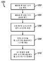
본 발명의 다른 양태에 따르면, 퍼커시브 테라피 디바이스에 대한 루틴을 실행하는 방법이 제공된다. 방법은 사용자 입력에 응답하여 퍼커시브 테라피 디바이스의 적어도 하나의 출력을 적용하도록 구성된 프로토콜을 개시하는 단계; 및 적어도 하나의 출력에 따라 퍼커시브 테라피 디바이스가 적용되는 프로토콜의 적어도 하나의 단계를 실행하는 단계를 포함한다. 바람직한 실시예에서, 적어도 하나의 출력은 퍼커시브 테라피 디바이스가 활성화되는(자동으로 또는 사용자에 의해) 지정된 시간 기간, 퍼커시브 테라피 디바이스의 부착물의 속도, 부착물의 힘, 부착물의 진폭, 부착물의 유형, 부착물의 온도, 퍼커시브 테라피 디바이스의 아암 위치 및 퍼커시브 테라피 디바이스의 파지 중 하나 이상을 포함한다.According to another aspect of the present invention, a method of executing a routine for a percussive therapy device is provided. The method includes initiating a protocol configured to apply at least one output of a percussive therapy device in response to a user input; and executing at least one step of the protocol to which the percussive therapy device is applied according to the at least one output. In a preferred embodiment, the at least one output is a specified period of time during which the percussive therapy device is activated (either automatically or by the user), the speed of the attachment of the percussive therapy device, the force of the attachment, the amplitude of the attachment, the type of attachment, and at least one of a temperature of the attachment, an arm position of the percussive therapy device, and a gripping of the percussive therapy device.
바람직한 실시예에서, 방법은 퍼커시브 테라피 디바이스의 부착물에 의해 인가되는 힘을 모니터링하는 단계; 및 사용자에게 힘을 디스플레이하는 단계를 포함한다. 바람직하게는, 힘은 사용자가 프로토콜의 적어도 하나의 단계에 의해 미리 결정된 목표 힘(범위일 수도 있음)에 대응하도록 힘을 조정할 수도 있게 사용자에게 디스플레이되도록 구성된다. 바람직하게는, 사용자는 프로토콜의 적어도 하나의 단계 동안 적어도 하나의 출력 중 하나 이상을 적용하도록 프롬프트받는다. 바람직한 실시예에서, 사용자 입력은 애플리케이션 인터페이스 및 터치스크린 중 적어도 하나를 통해 프로토콜을 개시한다. 바람직한 실시예에서, 프로토콜은 사용자의 하나 이상의 신체 부위에 치료 효과를 제공하도록 구성된다.In a preferred embodiment, the method includes monitoring a force applied by an attachment of a percussive therapy device; and displaying the force to the user. Preferably, the force is configured to be displayed to the user so that the user may adjust the force to correspond to a target force (which may be a range) predetermined by at least one step of the protocol. Preferably, the user is prompted to apply one or more of the at least one output during at least one step of the protocol. In a preferred embodiment, the user input initiates the protocol via at least one of an application interface and a touchscreen. In a preferred embodiment, the protocol is configured to provide a therapeutic effect to one or more body parts of the user.
본 발명의 다른 양태에 따르면, 퍼커시브 테라피 디바이스에 대한 루틴을 실행하는 방법이 제공되며, 이는 사용자 입력에 응답하여 퍼커시브 테라피 디바이스의 적어도 하나의 출력을 적용하도록 구성된 프로토콜을 개시하는 단계 및 적어도 하나의 출력에 따라 퍼커시브 테라피 디바이스가 적용되는 프로토콜의 적어도 하나의 단계를 개시하는 단계를 포함한다. 적어도 하나의 출력은 퍼커시브 테라피 디바이스가 활성화된 기간, 퍼커시브 테라피 디바이스의 부착물의 속도, 부착물의 진폭, 부착물에 의해 인가된 힘, 및 부착물에 의해 적용된 온도를 포함한다. 퍼커시브 테라피 디바이스는 퍼커시브 테라피 디바이스의 지정된 파지를 사용하고 프로토콜을 개시할 때 지정된 신체 부위에 부착물을 적용하라는 프롬프트를 제공하고, 부착물에 의해 인가되는 측정된 힘을 모니터링하고, 측정된 힘을 사용자에게 디스플레이하도록 구성되며, 여기서, 측정된 힘은 사용자가 프로토콜의 적어도 하나의 단계에 의해 미리 결정된 목표 힘에 대응하도록 인가된 힘을 조정할 수도 있게 사용자에게 디스플레이되도록 구성된다.According to another aspect of the present invention, a method of executing a routine for a percussive therapy device is provided, comprising: initiating a protocol configured to apply at least one output of the percussive therapy device in response to a user input and at least one and initiating at least one step of a protocol to which the percussive therapy device is applied according to the output of the . The at least one output includes a period during which the percussive therapy device has been activated, a velocity of an attachment of the percussive therapy device, an amplitude of the attachment, a force applied by the attachment, and a temperature applied by the attachment. The percussive therapy device uses the designated grip of the percussive therapy device and provides a prompt to apply an attachment to a designated body part when initiating a protocol, monitors the measured force applied by the attachment, and transmits the measured force to the user. and wherein the measured force is configured to be displayed to the user such that the user may adjust the applied force to correspond to a target force predetermined by at least one step of the protocol.
바람직한 실시예에서, 사용자는 퍼커시브 테라피 디바이스의 아암 위치를 설정하도록 프롬프트받고, 및/또는 사용자는 프로토콜의 적어도 하나의 단계 동안 새로운 지정된 신체 부위에 부착물을 적용하도록 프롬프트받고, 및/또는 사용자는 프로토콜의 적어도 하나의 단계 동안 퍼커시브 테라피 디바이스에 새로운 부착물을 부착하도록 프롬프트받고, 및/또는 사용자는 프로토콜의 적어도 하나의 단계 동안 신체 부위의 미리 결정된 하나의 지점에서 미리 결정된 제2 신체 부위로 부착물을 이동하도록 프롬프트받는다.In a preferred embodiment, the user is prompted to set the arm position of the percussive therapy device, and/or the user is prompted to apply an attachment to a new designated body part during at least one step of the protocol, and/or the user is prompted to apply the attachment to a new designated body part during at least one step of the protocol. is prompted to attach a new attachment to the percussive therapy device during at least one step of, and/or the user moves the attachment from a predetermined one point on the body part to a second predetermined body part during at least one step of the protocol prompted to do
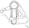
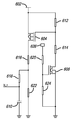
본 발명의 다른 양태에 따르면, 하우징, 전원, 하우징에 위치된 모터, 모터를 활성화하기 위한 스위치, 및 모터에 동작 가능하게 연결되어 모터의 활성화에 응답하여 왕복하도록 구성된 푸시 로드 조립체를 포함하는 퍼커시브 테라피 디바이스가 제공된다. 바람직한 실시예에서, 하우징은 핸들 개구를 규정하도록 협력하는 제1, 제2 및 제3 핸들부 및 헤드부를 포함한다. 제1 핸들부는 제1 축을 규정하고, 제2 핸들부는 제2 축을 규정하고, 제3 핸들부는 제3 축을 규정하고, 제1, 제2 및 제3 축은 협력하여 삼각형을 형성한다. 모터는 하우징의 헤드부에 위치되며, 푸시 로드 조립체의 적어도 일부는 헤드부의 외부로 연장된다. 바람직한 실시예에서, 제1 핸들부는 일반적으로 직선형이고, 제2 핸들부는 일반적으로 직선형이고, 제3 핸들부는 일반적으로 직선형이다.According to another aspect of the present invention, a percussive comprising a housing, a power source, a motor positioned in the housing, a switch for activating the motor, and a push rod assembly operatively connected to the motor and configured to reciprocate in response to activation of the motor. A therapy device is provided. In a preferred embodiment, the housing includes first, second and third handle portions and a head portion cooperating to define a handle opening. The first handle portion defines a first axis, the second handle portion defines a second axis, the third handle portion defines a third axis, and the first, second and third axes cooperate to form a triangle. The motor is located in the head portion of the housing, and at least a portion of the push rod assembly extends outside the head portion. In a preferred embodiment, the first handle portion is generally straight, the second handle portion is generally straight, and the third handle portion is generally straight.
바람직한 실시예에서, 퍼커시브 테라피 디바이스는 원격 디바이스에 연결하기 위한 무선 연결 디바이스(예를 들어, 블루투스 등)를 포함한다. 원격이라는 것은 퍼커시브 테라피 디바이스와 별개인 임의의 디바이스를 의미한다. 디바이스가 원격지에 있도록 멀리 떨어져 있을 필요는 없다. 바람직하게는, 전원은 선택적인 충전식 배터리이고, 퍼커시브 마사지 디바이스는 배터리와 전기적으로 통신하는 선택적인 무선 충전 수신기를 더 포함한다. 바람직하게는, 퍼커시브 테라피 디바이스는 선택적인 터치스크린을 포함한다.In a preferred embodiment, the percussive therapy device comprises a wirelessly connected device (eg, Bluetooth, etc.) for connecting to a remote device. By remote is meant any device separate from the percussive therapy device. The device does not have to be far away to be remote. Preferably, the power source is an optional rechargeable battery, and the percussive massage device further comprises an optional wireless charging receiver in electrical communication with the battery. Preferably, the percussive therapy device comprises an optional touch screen.
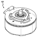
바람직한 실시예에서, 모터는 브러시리스 모터이고, 모터 장착부가 하우징에 위치하며, 모터는 모터 장착부에 고정되고, 모터 장착부는 하우징에 고정된다. 바람직하게는, 모터 장착부는 그 사이에 모터 장착부 내부를 규정하는 제1 및 제2 측벽을 포함한다. 모터는 제1 측벽에 고정되고 제2 측벽은 하우징에 고정된다. 바람직한 실시예에서, 모터는 모터 장착부의 제1 측벽에 규정된 돌기 개구를 통해 모터 장착부 내부로 연장되는 모터 샤프트를 포함하고, 푸시 로드 조립체의 적어도 일부는 모터 장착부 내부에 위치된다.In a preferred embodiment, the motor is a brushless motor, the motor mount is located in the housing, the motor is fixed to the motor mount, and the motor mount is fixed to the housing. Preferably, the motor mount includes first and second sidewalls therebetween defining the interior of the motor mount. The motor is secured to the first sidewall and the second sidewall is secured to the housing. In a preferred embodiment, the motor includes a motor shaft extending into the motor mount through a protruding opening defined in a first sidewall of the motor mount, and at least a portion of the push rod assembly is located within the motor mount.
바람직한 실시예에서, 퍼커시브 테라피 디바이스는 푸시 로드 조립체의 말단 단부에 연결된 부착물, 및 제1 치료 경로를 따라 제1 기간 동안 제1 신체 부위에 부착물을 적용하고 제2 치료 경로를 따라 제2 기간 동안 제1 또는 제2 신체 부위에 부착물을 적용하기 위해 사용자 명령을 제공하도록 구성된 프로토콜을 개시하도록 구성된 루틴 제어기를 포함한다. 바람직하게는, 사용자 명령은 퍼커시브 테라피 디바이스의 터치스크린을 통해 또는 원격 전자 디바이스의 애플리케이션 상에 제공된다. 바람직한 실시예에서, 퍼커시브 테라피 디바이스는 푸시 로드 조립체의 말단 단부에 연결된 부착물, 및 제1 기간 동안 제1 신체 부위에 부착물을 적용하고 제2 기간 동안 제1 또는 제2 신체 부위에 부착물을 적용하기 위해 사용자 명령을 제공하도록 구성된 프로토콜을 개시하도록 구성된 루틴 제어기를 포함한다. 루틴 제어기는 제1 기간 동안 제1 속도로 그리고 제2 기간 동안 제2 속도로 부착물을 왕복시키도록 구성된다.In a preferred embodiment, the percussive therapy device comprises an attachment connected to a distal end of the push rod assembly, and applying the attachment to a first body part for a first period along a first treatment path and for a second period along a second treatment path. and a routine controller configured to initiate a protocol configured to provide a user instruction to apply the attachment to the first or second body part. Preferably, the user commands are provided via a touchscreen of the percussive therapy device or on an application of a remote electronic device. In a preferred embodiment, the percussive therapy device comprises an attachment connected to a distal end of the push rod assembly, and applying the attachment to a first body part for a first period of time and applying the attachment to the first or second body part for a second period of time. and a routine controller configured to initiate a protocol configured to provide user instructions for The routine controller is configured to reciprocate the attachment at a first speed during a first time period and at a second speed during a second time period.
바람직한 실시예에서, 퍼커시브 테라피 디바이스는 적어도 제1 기간 및 후속하는 제2 기간 동안 모터를 활성화하기 위한 프로토콜을 개시하도록 구성된 루틴 제어기를 포함한다. 제1 기간 동안, 루틴 제어기는 제1 신체 부위를 치료하는 것, 제1 치료 경로를 따라 부착물을 이동시키는 것, 및 푸시 로드 조립체의 말단 단부에 제1 부착물을 연결하는 것 중 적어도 하나를 포함하는 제1 작업을 수행하기 위한 제1 사용자 명령을 제공하도록 구성되고, 제2 기간 동안 루틴 제어기는 제2 신체 부위를 치료하는 것, 제2 치료 경로를 따라 부착물을 이동시키는 것, 및 푸시 로드 조립체의 말단 단부에 제2 부착물을 연결하는 것 중 적어도 하나를 포함하는 제2 작업을 수행하기 위한 제2 사용자 명령을 제공하도록 구성된다. 제1 사용자 명령은 또한 제1, 제2 또는 제3 핸들부 중 하나를 파지하는 것에 관한 명령을 포함할 수도 있고, 제2 사용자 명령은 또한 제1, 제2 또는 제3 핸들부 중 동일한 부분 또는 다른 부분을 파지하는 것에 관한 명령을 포함할 수도 있다. 바람직하게는, 제1 및 제2 사용자 명령은 퍼커시브 테라피 디바이스의 터치스크린을 통해 또는 원격 전자 디바이스의 애플리케이션 상에 제공된다. 제1 사용자 명령은 (힘 측정기에 의한 판독에 기초하여) 제1 목표 힘을 인가하는 것에 관한 명령을 또한 포함할 수도 있고, 제2 사용자 명령은 (힘 측정기에 의한 판독에 기초하여) 제1 목표 힘 또는 제2 목표 힘을 인가하는 것에 관한 명령을 또한 포함할 수도 있다.In a preferred embodiment, the percussive therapy device comprises a routine controller configured to initiate a protocol for activating the motor for at least a first period and a subsequent second period of time. During the first time period, the routine controller comprises at least one of treating the first body part, moving the attachment along the first treatment path, and connecting the first attachment to the distal end of the push rod assembly. configured to provide a first user instruction to perform a first task, wherein during a second time period the routine controller is configured to treat the second body part, move the attachment along the second treatment path, and and provide a second user instruction to perform a second task comprising at least one of connecting a second attachment to the distal end. The first user instructions may also include instructions regarding gripping one of the first, second or third handle portions, wherein the second user instructions may also include the same portion of the first, second or third handle portions or It may also include instructions for gripping other parts. Preferably, the first and second user commands are provided via a touchscreen of the percussive therapy device or on an application of a remote electronic device. The first user command may also include instructions about applying a first target force (based on a reading by the force meter), and the second user command may include a command about applying a first target force (based on the reading by the force meter) to the first target (based on the reading by the force meter). It may also include instructions regarding applying a force or a second target force.
바람직한 실시예에서, 전원은 제2 핸들부에 위치되는 배터리이고, 배터리와 전기적으로 통신하는 무선 충전 수신기는 제3 핸들부에 위치된다.In a preferred embodiment, the power source is a battery located in the second handle portion and a wireless charging receiver in electrical communication with the battery is located in the third handle portion.
본 발명의 다른 양태에 따르면, 핸들 개구를 규정하기 위해 협력하는 제1, 제2 및 제3 핸들부를 포함하는 하우징, 전원, 하우징 내에 위치된 모터, 모터를 활성화하기 위한 스위치, 및 모터에 동작 가능하게 연결되고 모터의 활성화에 응답하여 왕복하도록 구성된 푸시 로드 조립체를 포함하는 퍼커시브 마사지 디바이스를 획득하는 단계를 포함하는 퍼커시브 마사지 디바이스의 사용 방법이 제공된다. 방법은 스위치를 사용하여 모터를 활성화하는 단계, 제1 핸들부를 파지하는 단계, 제1 신체 부위를 마사지하는 단계, 대안적으로 제2 핸들부를 파지하고 제1 신체 부위를 마사지하는 단계, 및 대안적으로 제3 핸들부를 파지하고 제1 신체 부위를 마사지하는 단계를 또한 포함한다. 바람직한 실시예에서, 제1 핸들부는 제1 축을 규정하고, 제2 핸들부는 제2 축을 규정하고, 제3 핸들부는 제3 축을 규정하고, 제1, 제2 및 제3 축은 삼각형을 형성하도록 협력한다. 바람직한 실시예에서, 방법은 제2 핸들부를 파지하는 단계, 제2 신체 부위를 마사지하는 단계, 제3 핸들부를 파지하는 단계, 및 제3 신체 부위를 마사지하는 단계를 또한 포함한다.According to another aspect of the present invention, a housing comprising first, second and third handle portions cooperating to define a handle opening, a power source, a motor located within the housing, a switch for activating the motor, and operable on the motor A method of using a percussive massage device is provided, the method comprising obtaining a percussive massage device that is tightly coupled and includes a push rod assembly configured to reciprocate in response to activation of a motor. The method includes activating the motor using the switch, gripping the first handle portion, massaging the first body portion, alternatively gripping the second handle portion and massaging the first body portion, and alternatively and holding the third handle portion with the aid of a massager and massaging the first body part. In a preferred embodiment, the first handle portion defines a first axis, the second handle portion defines a second axis, and the third handle portion defines a third axis, wherein the first, second and third axes cooperate to form a triangle . In a preferred embodiment, the method also comprises gripping the second handle portion, massaging the second body portion, gripping the third handle portion, and massaging the third body portion.
본 발명의 다른 양태에 따르면, 하우징, 전원, 하우징 내에 위치된 모터, 모터를 활성화하기 위한 스위치, 및 모터에 동작 가능하게 연결되고 모터의 활성화에 응답하여 왕복하도록 구성된 푸시 로드 조립체를 포함하는 퍼커시브 마사지 디바이스가 제공된다. 바람직한 실시예에서, 하우징은 핸들 개구를 규정하기 위해 협력하는 제1, 제2 및 제3 핸들부를 포함하고, 제1 핸들부는 제1 축을 규정하고, 제2 핸들부는 제2 축을 규정하고, 제3 핸들부는 제3 축을 규정하고, 제1, 제2 및 제3 축은 협력하여 삼각형을 형성한다.In accordance with another aspect of the present invention, a percussive comprising a housing, a power source, a motor positioned within the housing, a switch for activating the motor, and a push rod assembly operatively connected to the motor and configured to reciprocate in response to activation of the motor. A massage device is provided. In a preferred embodiment, the housing comprises first, second and third handle portions cooperating to define a handle opening, the first handle portion defining a first axis, the second handle portion defining a second axis, and a third The handle portion defines a third axis, wherein the first, second and third axes cooperate to form a triangle.
바람직하게는, 제1 핸들부는 제1 핸들부 내부 에지를 포함하고 제1 핸들부 길이를 규정하고, 제1 핸들부 길이는, 사용자가 손으로 제1 핸들부를 파지할 때 3개의 손가락의 적어도 일부가 핸들 개구를 통해 연장되고 제1 핸들부 내부 에지와 접촉하도록 충분히 길다. 바람직하게는, 제2 핸들부는 제2 핸들부 내부 에지를 포함하고 제2 핸들부 길이를 규정하고, 제2 핸들부 길이는, 사용자가 손으로 제2 핸들부를 파지할 때 3개의 손가락의 적어도 일부가 핸들 개구를 통해 연장되고 제2 핸들부 내부 에지와 접촉하도록 충분히 길다. 바람직하게는, 제3 핸들부는 제3 핸들부 내부 에지를 포함하고 제3 핸들부 길이를 규정하고, 제3 핸들부 길이는, 사용자가 손으로 제3 핸들부를 파지할 때 3개의 손가락의 적어도 일부가 핸들 개구를 통해 연장되고 제3 핸들부 내부 에지와 접촉하도록 충분히 길다. 바람직한 실시예에서, 제1 핸들부는 일반적으로 직선형이고, 제2 핸들부는 일반적으로 직선형이고, 제3 핸들부는 일반적으로 직선형이다. 일반적으로 직선형이라는 것은 핸들부의 대부분이 직선형이지만, 상이한 핸들부가 만나거나 핸들부가 팽윤부 또는 손가락 돌기 등과 만나는 라운딩된 에지 또는 코너를 포함할 수 있다는 것을 의미한다.Preferably, the first handle portion includes an inner edge of the first handle portion and defines a first handle portion length, wherein the first handle portion length is at least a portion of three fingers when the user grips the first handle portion by hand. is long enough to extend through the handle opening and contact the inner edge of the first handle portion. Preferably, the second handle portion includes an inner edge of the second handle portion and defines a second handle portion length, wherein the second handle portion length is at least a portion of three fingers when the user grips the second handle portion by hand. is long enough to extend through the handle opening and contact the inner edge of the second handle portion. Preferably, the third handle portion includes an inner edge of the third handle portion and defines a third handle portion length, wherein the third handle portion length is at least a portion of three fingers when the user grips the third handle portion by hand. is long enough to extend through the handle opening and contact the inner edge of the third handle portion. In a preferred embodiment, the first handle portion is generally straight, the second handle portion is generally straight, and the third handle portion is generally straight. By generally straight it is meant that the majority of the handle portions are straight, but may include rounded edges or corners where different handle portions meet or where the handle portions meet bulges or finger protrusions or the like.
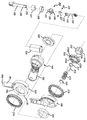
바람직한 실시예에서, 스위치는 그와 관련된 스위치 전자 기기를 포함하고, 전원은 제2 핸들부에 수용된 배터리이고 스위치 전자 기기는 제1 핸들부에 수용된다. 바람직하게는, 모터는 피니언 기어를 갖는 피니언 샤프트를 샤프트 회전축을 중심으로 회전시키도록 구성된다. 하우징은 피니언 기어와 동작 가능하게 맞물리고 기어 회전축을 중심으로 회전하는, 그 내에 배치된 기어 부재를 포함한다. 푸시 로드 조립체는 기어 부재에 동작 가능하게 연결되며, 피니언 샤프트의 회전 운동은 피니언 기어와 기어 부재의 맞물림을 통해 푸시 로드 조립체의 왕복 운동으로 변환된다. 모터는 그로부터 외향으로 연장하는 모터 샤프트를 포함하고 피니언 커플링 조립체가 모터 샤프트와 피니언 샤프트 사이에 위치된다. 피니언 커플링은 모터 샤프트에 동작 가능하게 연결된 하부 커넥터, 피니언 샤프트에 동작 가능하게 연결된 상부 커넥터, 및 하부 커넥터와 상부 커넥터 사이에 위치된 크로스 커플링을 포함한다. 바람직한 실시예에서, 하부 커넥터는 모터 샤프트를 수용하는 중앙 개구를 규정하는 본체부 및 본체부로부터 외향으로 연장하는 제1 및 제2 하부 커넥터 아암을 포함하고, 상부 커넥터는 피니언 샤프트를 수용하는 중앙 개구를 규정하는 본체부 및 본체부로부터 외향으로 연장하는 제1 및 제2 상부 커넥터 아암을 포함하고, 크로스 커플링은 반경방향으로 연장되는 리브를 포함하고, 제1 및 제2 하부 커넥터 부재와 제1 및 제2 상부 커넥터 부재는 반경방향으로 연장되는 리브와 동작 가능하게 맞물린다. 바람직하게는, 하부 및 상부 커넥터는 플라스틱을 포함하고 크로스 커플링은 엘라스토머를 포함한다.In a preferred embodiment, the switch includes switch electronics associated therewith, the power source is a battery housed in the second handle section and the switch electronics are housed in the first handle section. Preferably, the motor is configured to rotate a pinion shaft having a pinion gear about an axis of rotation of the shaft. The housing includes a gear member disposed therein that is operatively engaged with the pinion gear and rotates about an axis of rotation of the gear. The push rod assembly is operatively connected to the gear member, and rotational motion of the pinion shaft is converted into reciprocating motion of the push rod assembly through engagement of the pinion gear and the gear member. The motor includes a motor shaft extending outwardly therefrom and a pinion coupling assembly is positioned between the motor shaft and the pinion shaft. The pinion coupling includes a lower connector operatively connected to the motor shaft, an upper connector operatively connected to the pinion shaft, and a cross coupling positioned between the lower connector and the upper connector. In a preferred embodiment, the lower connector includes a body portion defining a central opening for receiving the motor shaft and first and second lower connector arms extending outwardly from the body portion, the upper connector including the central opening for receiving the pinion shaft a body portion defining a body portion and first and second upper connector arms extending outwardly from the body portion, the cross coupling including radially extending ribs; and the second upper connector member operatively engages the radially extending rib. Preferably, the lower and upper connectors comprise plastic and the cross coupling comprises elastomer.
바람직한 실시예에서, 기어 부재는 적어도 제1 위치와 제2 위치 사이에서 회전 가능한 회전 하우징 내에 배치된다. 기어 부재를 수용하는 기어박스 하우징이 회전 하우징 내에 배치된다. 기어박스 하우징은 그 내에 규정된 제1 및 제2 단부를 갖는 간극 슬롯을 포함한다. 푸시 로드 조립체는, 회전 하우징이 제1 위치로부터 제2 위치로 회전될 때, 푸시 로드 조립체가 제1 단부의 인접부로부터 제2 단부의 인접부로 간극 슬롯 내에서 이동하도록, 간극 슬롯을 통해 연장된다.In a preferred embodiment, the gear member is arranged in a rotating housing rotatable between at least a first position and a second position. A gearbox housing for receiving the gear member is disposed within the rotating housing. The gearbox housing includes a gap slot having first and second ends defined therein. The push rod assembly extends through the gap slot such that when the rotating housing is rotated from the first position to the second position, the push rod assembly moves within the gap slot from a proximal first end to an adjacent second end. .
바람직한 실시예에서, 푸시 로드 조립체는 기단 단부 및 말단 단부를 갖는 제1 로드부 및 기단 단부 및 말단 단부를 갖는 제2 로드부를 포함한다. 제1 로드부의 기단 단부는 모터에 동작 가능하게 연결된다. 어댑터 조립체가 제1 및 제2 로드부 사이에 위치된다. 어댑터 조립체는 제1 로드부가 제2 로드부에 대해 피봇하게 한다. 바람직하게는, 어댑터 조립체는 그 내에 제1 로드부의 말단 단부를 수용하는 포켓을 포함하는 어댑터 부재를 포함한다. 피봇 핀이 포켓에 걸쳐 있고 제1 로드부의 말단 단부를 통해 연장된다. 바람직한 실시예에서, 어댑터 부재는 제2 로드부의 기단 단부에 수용되는 돌기를 포함한다.In a preferred embodiment, the push rod assembly includes a first rod portion having a proximal end and a distal end and a second rod portion having a proximal end and a distal end. The proximal end of the first rod portion is operatively connected to the motor. An adapter assembly is positioned between the first and second rod portions. The adapter assembly causes the first rod portion to pivot relative to the second rod portion. Preferably, the adapter assembly includes an adapter member including a pocket for receiving therein a distal end of the first rod portion. A pivot pin spans the pocket and extends through the distal end of the first rod portion. In a preferred embodiment, the adapter member includes a protrusion received at the proximal end of the second rod portion.
본 발명의 다른 양태에 따르면, 하우징, 전기 입력부, 모터, 전기 입력부 및 모터와 전기적으로 통신하고 전기 입력부로부터 모터로 전력을 선택적으로 제공하도록 구성된 스위치, 모터에 동작 가능하게 연결되고 모터의 활성화에 응답하여 왕복하도록 구성된 피동 출력부, 및 피동 출력부의 말단 단부에 동작 가능하게 연결된 치료 구조체를 포함하는 마사지 디바이스가 제공된다. 피동 출력부는 약 15 Hz 내지 약 100 Hz의 주파수 및 약 0.15 내지 약 1.0 인치의 진폭에서 치료 구조체를 왕복시키도록 구성된다. 진폭 및 주파수의 조합은 치료 구조체가 사용자의 타겟화된 근육에 치료적으로 유익한 치료를 제공하도록 치료 구조체의 효율적인 왕복을 제공한다.According to another aspect of the invention, there is provided a housing, an electrical input, a motor, an electrical input, and a switch configured to be in electrical communication with the motor and selectively provide power from the electrical input to the motor, operatively connected to the motor and responsive to activation of the motor. A massage device is provided that includes a driven output configured to reciprocate by using a massager, and a treatment structure operatively coupled to a distal end of the driven output. The driven output is configured to reciprocate the treatment structure at a frequency of about 15 Hz to about 100 Hz and an amplitude of about 0.15 to about 1.0 inches. The combination of amplitude and frequency provides for efficient reciprocation of the treatment structure such that the treatment structure provides a therapeutically beneficial treatment to the targeted muscle of the user.
바람직한 실시예에서, 피동 출력부는 약 25 Hz 내지 약 48 Hz의 주파수 및 약 0.23 내지 약 0.70 인치의 진폭에서 치료 구조체를 왕복시키도록 구성된다. 다른 바람직한 실시예에서, 피동 출력부는 약 33 Hz 내지 약 42 Hz의 주파수 및 약 0.35 내지 약 0.65 인치의 진폭에서 치료 구조체를 왕복시키도록 구성된다.In a preferred embodiment, the driven output is configured to reciprocate the treatment structure at a frequency of about 25 Hz to about 48 Hz and an amplitude of about 0.23 to about 0.70 inches. In another preferred embodiment, the driven output is configured to reciprocate the treatment structure at a frequency of about 33 Hz to about 42 Hz and an amplitude of about 0.35 to about 0.65 inches.
본 발명의 다른 양태에 따르면, 하우징, 전원, 하우징에 위치된 모터, 모터를 활성화하기 위한 스위치, 및 제어기를 포함하는 힘 측정기를 갖는 퍼커시브 마사지 디바이스가 제공되고, 제어기는 모터의 전압을 획득하고, 퍼커시브 마사지 디바이스에 의해 인가된 힘에 전압을 상관시키는 참조표를 생성하고, 참조표를 사용하여 획득된 전압에 대응하는 힘 크기를 디스플레이하도록 구성된다. 바람직한 실시예에서, 참조표는 퍼커시브 마사지 디바이스에 의해 인가되도록 구성된 힘의 최대 크기를 결정하고, 전원으로부터 퍼커시브 마사지 디바이스에 인가되도록 구성된 전압의 최대 크기를 결정하고, 힘의 최대 크기를 동일한 힘 증분으로 나누고, 전압의 최대 크기를 동일한 전압 증분으로 나누는 것에 의해 생성된다. 동일한 힘 증분의 수와 동일한 전압 증분의 수는 동일하다. 바람직하게는, 퍼커시브 마사지 디바이스는 배터리 팩 및 퍼커시브 마사지 디바이스에 의해 인가되는 힘의 양을 나타내도록 구성된 디스플레이를 포함한다. 바람직한 실시예에서, 디스플레이는 일련의 LED를 포함한다. 바람직한 실시예에서, 퍼커시브 마사지 디바이스는 유기 발광 다이오드 스크린을 포함한다.According to another aspect of the present invention, there is provided a percussive massage device having a force meter comprising a housing, a power source, a motor positioned in the housing, a switch for activating the motor, and a controller, wherein the controller obtains a voltage of the motor and , generate a look-up table correlating the voltage to the force applied by the percussive massage device, and display the force magnitude corresponding to the obtained voltage using the look-up table. In a preferred embodiment, the look-up table determines the maximum magnitude of a force configured to be applied by the percussive massage device, determines the maximum magnitude of the voltage configured to be applied to the percussive massage device from the power source, and determines the maximum magnitude of the force to be equal to the force It is created by dividing by the increment and dividing the maximum magnitude of the voltage by the same voltage increment. The same number of force increments equals the same number of voltage increments. Preferably, the percussive massage device comprises a battery pack and a display configured to indicate an amount of force applied by the percussive massage device. In a preferred embodiment, the display comprises a series of LEDs. In a preferred embodiment, the percussive massage device comprises an organic light emitting diode screen.
바람직한 실시예에서, 모터는 브러시리스 직류(BLDC) 모터이다. 바람직하게는, 퍼커시브 마사지 디바이스는 BLDC 모터 및 제어기에 전기적으로 결합된 전압 감지 저항기를 포함한다.In a preferred embodiment, the motor is a brushless direct current (BLDC) motor. Preferably, the percussive massage device comprises a voltage sense resistor electrically coupled to the BLDC motor and the controller.
본 발명의 다른 양태에 따르면, 퍼커시브 마사지 디바이스의 모터의 전압을 획득하는 단계, 퍼커시브 마사지 디바이스에 의해 인가되는 힘에 대한 전압을 상관시키는 참조표를 생성하는 단계 및 참조표를 사용하여 획득된 전압에 대응하는 힘 크기를 디스플레이하는 단계를 포함하는 퍼커시브 마사지 디바이스의 힘을 디스플레이하는 방법이 제공된다. 바람직한 실시예에서, 전압과 힘을 상관시키는 참조표는 선형적이다. 바람직하게는, 참조표는 퍼커시브 마사지 디바이스에 의해 인가되도록 구성된 힘의 최대 크기를 결정하고, 전원으로부터 퍼커시브 마사지 디바이스에 인가되도록 구성된 전압의 최대 크기를 결정하고, 힘의 최대 크기를 동일한 힘 증분으로 나누고, 전압의 최대 크기를 동일한 전압 증분으로 나누는 것에 의해 생성되고, 동일한 힘 증분의 수와 동일한 전압 증분의 수는 동일하다.According to another aspect of the present invention, there is provided a method for obtaining a voltage of a motor of a percussive massage device, generating a look-up table correlating the voltage with respect to a force applied by the percussive massage device, and using the look-up table. A method of displaying a force of a percussive massage device is provided comprising the step of displaying a force magnitude corresponding to a voltage. In a preferred embodiment, the lookup table correlating voltage and force is linear. Preferably, the look-up table determines a maximum magnitude of a force configured to be applied by the percussive massage device, determines a maximum magnitude of a voltage configured to be applied to the percussive massage device from a power source, and determines the maximum magnitude of the force in equal force increments , produced by dividing the maximum magnitude of the voltage by the same voltage increment, the number of equal force increments equals the same number of voltage increments.
바람직한 실시예에서, 방법은 퍼커시브 마사지 디바이스의 최대 전원 전압을 획득하는 단계; 최대 전원 전압을 전압의 최대 크기로 설정하는 단계; 전압의 최대 크기를 동일한 전압 증분으로 나누는 단계로서, 동일한 힘 증분의 수와 동일한 전압 증분의 수는 동일한, 단계; 최대 전원 전압에 의해 결정된 전압 범위에 대응하는 퍼커시브 마사지 디바이스에 의해 인가된 힘에 전압을 상관시키는 업데이트된 참조표를 생성하는 단계 및 업데이트된 참조표를 사용하여 전원 전압에 대응하는 교정된 힘 크기를 디스플레이하는 단계를 포함한다. 바람직한 실시예에서, 방법은 각각 힘의 크기에 대응하는 적어도 2개의 전원 전압을 획득하는 단계로서, 힘의 크기는 디스플레이된 힘 크기로부터 결정되는, 단계; 적어도 2개의 전원 전압 각각에 대해 외력 측정기를 사용하여 퍼커시브 마사지 디바이스에 의해 작용된 힘의 크기를 측정하는 단계 및 측정된 힘의 크기에 대응하는 퍼커시브 마사지 디바이스에 의해 인가된 힘에 전압을 상관시키는 업데이트된 참조표를 생성하는 단계를 포함한다.In a preferred embodiment, the method includes: obtaining a maximum power supply voltage of the percussive massage device; setting the maximum supply voltage to the maximum magnitude of the voltage; dividing the maximum magnitude of the voltage by equal voltage increments, wherein the same number of force increments and the same number of voltage increments are equal; generating an updated look-up table correlating the voltage to the force applied by the percussive massage device corresponding to the voltage range determined by the maximum power supply voltage, and using the updated look-up table the corrected force magnitude corresponding to the power supply voltage and displaying In a preferred embodiment, the method comprises the steps of: obtaining at least two power supply voltages each corresponding to a magnitude of a force, the magnitude of the force being determined from the displayed magnitude of the force; measuring the magnitude of the force applied by the percussive massage device using an external force meter for each of the at least two power supply voltages and correlating the voltage to the force applied by the percussive massage device corresponding to the measured magnitude of the force and generating an updated lookup table.
바람직한 실시예에서, 방법은 업데이트된 참조표를 사용하여 측정된 힘의 크기에 대응하는 교정된 힘 크기를 디스플레이하는 단계를 포함한다. 바람직하게는, 참조표는 퍼커시브 마사지 디바이스에 디스플레이될 수 있는 각각의 힘의 크기에 대해 업데이트된다.In a preferred embodiment, the method comprises displaying a calibrated force magnitude corresponding to the measured force magnitude using the updated look-up table. Preferably, the look-up table is updated for each magnitude of force that can be displayed on the percussive massage device.
본 발명의 다른 양태에 따르면, 퍼커시브 마사지 디바이스의 힘을 디스플레이하는 방법이 제공되고, 이는 퍼커시브 마사지 디바이스의 배터리 팩의 전류 크기를 획득하는 단계, 배터리 팩의 전압 크기를 획득하는 단계, 배터리 팩의 전류 크기 및 전압 크기를 사용하여 전력 크기를 결정하는 단계, 퍼커시브 마사지 디바이스에 의해 인가되는 힘 크기에 전력 크기를 상관시키는 참조표를 생성하는 단계 및 참조표를 사용하여 획득된 전력 크기에 대응하는 힘 크기를 디스플레이하는 단계를 포함한다. 바람직한 실시예에서, 힘 크기는 힘 크기에 대응하여 활성화되는 일련의 LED를 이용하여 디스플레이된다. 바람직하게는, 참조표는 퍼커시브 마사지 디바이스에 입력될 최대 전력 크기를 결정하고, 퍼커시브 마사지 디바이스에 부하가 인가되지 않은 경우 퍼커시브 마사지 디바이스의 최소 전력 크기를 결정하고, 전원으로부터 퍼커시브 마사지 디바이스에 인가되도록 구성된 최대 힘 크기를 결정하고, 최대 전력 크기를 동일한 전력 증분으로 나누고, 최대 힘 크기를 동일한 힘 증분으로 나누는 것에 의해 생성된다. 동일한 전력 증분의 수와 동일한 힘 증분의 수는 동일하다. 바람직하게는, 최대 전력 크기는 총 유효 전력으로부터 도출된 최대 유효 전력 크기이다.According to another aspect of the present invention, there is provided a method for displaying the force of a percussive massage device, comprising the steps of: obtaining a current magnitude of a battery pack of the percussive massage device; acquiring a voltage magnitude of the battery pack; determining the magnitude of the power using the magnitude of the current and magnitude of the voltage of and displaying the magnitude of the force. In a preferred embodiment, the force magnitude is displayed using a series of LEDs that are activated in response to the force magnitude. Preferably, the lookup table determines the maximum amount of power to be input to the percussive massage device, determines the minimum amount of power of the percussive massage device when no load is applied to the percussive massage device, and from the power source to the percussive massage device is generated by determining the maximum force magnitude configured to be applied to the , dividing the maximum power magnitude by the equal power increment, and dividing the maximum force magnitude by the same force increment. The number of equal power increments is equal to the number of equal force increments. Preferably, the maximum power magnitude is the maximum active power magnitude derived from the total active power.
바람직한 실시예에서, 방법은 각각 힘의 크기에 대응하는 배터리 팩의 전류 및 전압 측정치를 사용하여 적어도 2개의 전력 크기를 결정하는 단계를 포함한다. 힘의 크기는 디스플레이된 힘 크기로부터 결정된다. 적어도 2개의 전력 크기 각각에 대해 외력 측정기를 사용하여 퍼커시브 마사지 디바이스에 의해 작용된 힘의 크기를 측정하고, 측정된 힘 크기에 대응하는 퍼커시브 마사지 디바이스에 의해 인가된 힘에 대해 전력을 상관시키는 업데이트된 참조표를 생성한다. 바람직한 실시예에서, 방법은 업데이트된 참조표를 사용하여 측정된 힘의 크기에 대응하는 교정된 힘 크기를 디스플레이하는 단계를 포함한다. 바람직하게는, 참조표는 퍼커시브 마사지 디바이스에 디스플레이될 수 있는 각각의 힘의 크기에 대해 업데이트된다.In a preferred embodiment, the method comprises determining at least two power magnitudes using current and voltage measurements of the battery pack, each corresponding to the magnitude of the force. The magnitude of the force is determined from the displayed force magnitude. measuring the magnitude of the force applied by the percussive massage device using an external force meter for each of the at least two power magnitudes, and correlating the power to the force applied by the percussive massage device corresponding to the measured magnitude of force. Create an updated lookup table. In a preferred embodiment, the method comprises displaying a calibrated force magnitude corresponding to the measured force magnitude using the updated look-up table. Preferably, the look-up table is updated for each magnitude of force that can be displayed on the percussive massage device.
본 명세서에 설명된 본 발명의 특징은 임의의 유형의 퍼커시브 마사지 디바이스와 함께 사용될 수 있다는 것을 이해할 것이다. 예를 들어, 본 명세서에 교시된 힘 측정기 및 기타 특징은 미국 특허 제10,357,425호("'425 특허")에 개시된 퍼커시브 마사지 디바이스와 함께 사용될 수 있으며, 이의 전체 내용은 본 명세서에 참조로 합체된다.It will be appreciated that the features of the invention described herein may be used with any type of percussive massage device. For example, the force meter and other features taught herein may be used with the percussive massage device disclosed in US Patent No. 10,357,425 ("'425 Patent"), the entire contents of which are incorporated herein by reference. .
일 실시예에서, 비일시적 컴퓨터-판독 가능 매체는 소프트웨어 명령어를 저장하고 있고, 이 소프트웨어 명령어는 프로세서에 의해 실행될 때 프로세서로 하여금 퍼커시브 마사지 디바이스의 모터의 전압을 획득하고, 퍼커시브 마사지 디바이스에 의해 인가된 힘에 전압을 상관시키는 참조표를 생성하고, 참조표를 사용하여 획득한 전압에 대응하는 힘 크기를 디스플레이하도록 한다.In one embodiment, the non-transitory computer-readable medium stores software instructions that, when executed by a processor, cause the processor to obtain a voltage of a motor of the percussive massage device, and Generate a lookup table correlating the voltage to the applied force, and use the lookup table to display the force magnitude corresponding to the obtained voltage.
바람직한 실시예에서, 참조표는 퍼커시브 마사지 디바이스에 의해 인가되도록 구성된 힘의 최대 크기를 결정하고, 전원으로부터 퍼커시브 마사지 디바이스에 인가되도록 구성된 전압의 최대 크기를 결정하고, 힘의 최대 크기를 동일한 힘 증분으로 나누고, 전압의 최대 크기를 동일한 전압 증분으로 나누는 것에 의해 생성된다. 일 실시예에서, 동일한 힘 증분의 수와 동일한 전압 증분의 수는 동일하다.In a preferred embodiment, the look-up table determines the maximum magnitude of a force configured to be applied by the percussive massage device, determines the maximum magnitude of the voltage configured to be applied to the percussive massage device from the power source, and determines the maximum magnitude of the force to be equal to the force It is created by dividing by the increment and dividing the maximum magnitude of the voltage by the same voltage increment. In one embodiment, the same number of force increments and the same number of voltage increments are equal.
다른 실시예에서, 비일시적 컴퓨터-판독 가능 매체는 소프트웨어 명령어를 저장하고 있고, 이 소프트웨어 명령어는 프로세서에 의해 실행될 때 프로세서로 하여금 퍼커시브 마사지 디바이스의 최대 전원 전압을 획득하고, 최대 전원 전압을 전압의 최대 크기가 되도록 설정하고, 전압의 최대 크기를 동일한 전압 증분으로 나누고, 최대 전원 전압에 의해 결정된 전압 범위에 대응하는 퍼커시브 마사지 디바이스에 의해 인가된 힘에 전압을 상관시키는 업데이트된 참조표를 생성하고, 업데이트된 참조표를 사용하여 전원 전압에 대응하는 교정된 힘 크기를 디스플레이하도록 한다.In another embodiment, the non-transitory computer-readable medium stores software instructions that, when executed by the processor, cause the processor to obtain a maximum power supply voltage of the percussive massage device, and convert the maximum power supply voltage to a value of the voltage. set to be the maximum magnitude, divide the maximum magnitude of the voltage by equal voltage increments, generate an updated lookup table correlating the voltage to the force applied by the percussive massage device corresponding to the voltage range determined by the maximum supply voltage, and , use the updated lookup table to display the calibrated force magnitude corresponding to the supply voltage.
다른 실시예에서, 비일시적 컴퓨터-판독 가능 매체는 소프트웨어 명령어를 저장하고 있고, 이 소프트웨어 명령어는 프로세서에 의해 실행될 때 프로세서로 하여금, 디스플레이된 힘 크기로부터 결정되는 힘의 크기에 각각 대응하는 적어도 2개의 전원 전압을 획득하고, 적어도 2개의 전원 전압 각각에 대해 외력 측정기를 사용하여 퍼커시브 마사지 디바이스에 의해 작용되는 힘의 크기를 측정하고; 측정된 힘의 크기에 대응하는 퍼커시브 마사지 디바이스에 의해 인가된 힘에 전압을 상관시키는 업데이트된 참조표를 생성하게 한다.In another embodiment, the non-transitory computer-readable medium stores software instructions that, when executed by the processor, cause the processor to: acquiring a power supply voltage, and measuring a magnitude of a force applied by the percussive massage device using an external force meter for each of the at least two power supply voltages; generate an updated lookup table correlating the voltage to the force applied by the percussive massage device corresponding to the magnitude of the measured force.
일 실시예에서, 비일시적 컴퓨터-판독 가능 매체는 소프트웨어 명령어를 저장하고 있고, 이 소프트웨어 명령어는 프로세서에 의해 실행될 때 프로세서로 하여금 퍼커시브 마사지 디바이스의 배터리 팩의 전류 크기를 획득하고, 배터리 팩의 전압 크기를 획득하고, 배터리 팩의 전류 크기와 전압 크기를 사용하여 전력 크기를 결정하고, 퍼커시브 마사지 디바이스에 의해 인가되는 힘 크기에 전력 크기를 상관시키는 참조표를 생성하고, 참조표를 사용하여 획득된 전력 크기에 대응하는 힘 크기를 디스플레이하게 한다.In one embodiment, the non-transitory computer-readable medium stores software instructions that, when executed by the processor, cause the processor to obtain a current magnitude of the battery pack of the percussive massage device, and to obtain a voltage of the battery pack. Obtain the magnitude, determine the power magnitude using the current magnitude and voltage magnitude of the battery pack, generate a lookup table correlating the power magnitude to the force magnitude applied by the percussive massage device, and obtain using the lookup table Display the force magnitude corresponding to the applied power magnitude.
일 실시예에서, 비일시적 컴퓨터-판독 가능 매체는 소프트웨어 명령어를 저장하고 있고, 이 소프트웨어 명령어는 프로세서에 의해 실행될 때, 프로세서로 하여금, 디스플레이된 힘 크기로부터 결정되는 힘의 크기에 각각 대응하는 배터리 팩의 전류 및 전압 측정치를 사용하여 적어도 2개의 전력 크기를 결정하고, 적어도 2개의 전력 크기 각각에 대해 외력 측정기를 사용하여 퍼커시브 마사지 디바이스에 의해 작용된 힘의 크기를 측정하고, 측정된 힘의 크기에 대응하는 퍼커시브 마사지 디바이스에 의해 인가된 힘에 전력을 상관시키는 업데이트된 참조표를 생성하게 한다.In one embodiment, the non-transitory computer-readable medium stores software instructions that, when executed by a processor, cause the processor to cause a battery pack each corresponding to a magnitude of force determined from a displayed magnitude of force. determine at least two power magnitudes using the current and voltage measurements of generate an updated lookup table correlating power to the force applied by the percussive massage device corresponding to
바람직한 실시예에서, 모터는 일 실시예에서 전원으로부터의 전력을 운동으로 변환한다. 몇몇 실시예에서, 모터는 전기 모터이다. 전기 모터는 이들에 한정되는 것은 아니지만, 브러시 모터, 브러시리스 모터, 직류(DC) 모터, 교류(AC) 모터, 기계-정류자 모터, 전자 정류자 모터 또는 외부 정류 모터를 포함하는 관련기술 분야에 공지된 임의의 유형의 전기 모터일 수도 있다.In a preferred embodiment, the motor, in one embodiment, converts power from a power source into motion. In some embodiments, the motor is an electric motor. Electric motors are known in the art including, but not limited to, brush motors, brushless motors, direct current (DC) motors, alternating current (AC) motors, mechanical-commutator motors, electronic commutator motors, or external commutation motors. It may be any type of electric motor.
몇몇 실시예에서, 피동 출력부 또는 출력 샤프트는 대략 65 Hz의 속도로 왕복한다. 피동 출력부는 몇몇 실시예에서, 50 Hz 초과의 속도로 왕복한다. 왕복 치료 디바이스는 몇몇 실시예에서, 50 Hz 내지 80 Hz 범위의 속도로 왕복을 제공한다. 몇몇 실시예에서, 피동 출력부는 50 Hz 내지 80 Hz의 최대 굴절 속도(articulation rate)를 갖는다. 다른 실시예에서, 피동 출력부는 30 Hz 내지 80 Hz의 굴절 속도를 갖는다. 특정 실시예에서, 피동 출력부는 대략 37 Hz의 굴절 속도를 갖는다. 일 실시예에서, 피동 출력부는 대략 60 Hz의 굴절 속도를 갖는다. 바람직한 실시예에서, 피동 출력부는 약 15 Hz 내지 약 100 Hz의 주파수에서 굴절 또는 왕복한다. 더 바람직한 실시예에서, 피동 출력부는 약 25 Hz 내지 약 48 Hz의 주파수에서 굴절 또는 왕복한다. 가장 바람직한 실시예에서, 피동 출력부는 약 33 Hz 내지 약 42 Hz의 주파수에서 굴절 또는 왕복한다. 지정된 범위 내의 임의의 선택된 범위가 본 발명의 범위 내에 있다.In some embodiments, the driven output or output shaft reciprocates at a rate of approximately 65 Hz. The driven output, in some embodiments, reciprocates at a rate greater than 50 Hz. The reciprocating treatment device, in some embodiments, provides reciprocation at a rate ranging from 50 Hz to 80 Hz. In some embodiments, the driven output has a maximum articulation rate between 50 Hz and 80 Hz. In another embodiment, the driven output has a refractive rate between 30 Hz and 80 Hz. In a particular embodiment, the driven output has a refractive rate of approximately 37 Hz. In one embodiment, the driven output has a refractive rate of approximately 60 Hz. In a preferred embodiment, the driven output deflects or reciprocates at a frequency of about 15 Hz to about 100 Hz. In a more preferred embodiment, the driven output deflects or reciprocates at a frequency of about 25 Hz to about 48 Hz. In a most preferred embodiment, the driven output deflects or reciprocates at a frequency of about 33 Hz to about 42 Hz. Any selected range within the specified range is within the scope of the present invention.
피동 출력부는 미리 결정된 왕복 범위를 통해 이동할 수도 있다. 예를 들어, 피동 출력부는 1/2 인치의 진폭을 갖도록 구성될 수도 있다. 다른 실시예에서, 피동 출력부는 1/4 인치의 진폭을 갖도록 구성될 수도 있다. 통상의 기술자에 의해 이해될 수도 있는 바와 같이, 피동 출력부는 치료적으로 유익한 것으로 간주되는 임의의 진폭을 갖도록 구성될 수도 있다.The driven output may move through a predetermined reciprocating range. For example, the driven output may be configured to have an amplitude of 1/2 inch. In another embodiment, the driven output may be configured to have an amplitude of 1/4 inch. As may be appreciated by one of ordinary skill in the art, the driven output may be configured to have any amplitude deemed therapeutically beneficial.
몇몇 실시예에서, 피동 출력부는 가변 범위의 왕복을 통해 조정 가능할 수도 있다. 예를 들어, 왕복 치료 디바이스는 1/4 인치로부터 최대 1 인치의 범위까지 왕복 진폭을 조정하기 위한 입력부를 포함할 수도 있다. 바람직한 실시예에서, 피동 출력부는 약 0.15 인치 내지 약 1.0 인치의 진폭을 통해 이동한다. 더 바람직한 실시예에서, 피동 출력부는 약 0.23 인치 내지 약 0.70 인치의 주파수에서 굴절 또는 왕복한다. 가장 바람직한 실시예에서, 피동 출력부는 약 0.35 인치 내지 약 0.65 인치의 주파수에서 굴절 또는 왕복한다. 지정된 범위 내의 임의의 선택된 범위가 본 발명의 범위 내에 있다.In some embodiments, the driven output may be adjustable through a variable range of reciprocation. For example, the reciprocating treatment device may include an input for adjusting the reciprocating amplitude from a range of 1/4 inch up to 1 inch. In a preferred embodiment, the driven output travels through an amplitude of about 0.15 inches to about 1.0 inches. In a more preferred embodiment, the driven output deflects or reciprocates at a frequency of about 0.23 inches to about 0.70 inches. In a most preferred embodiment, the driven output deflects or reciprocates at a frequency of about 0.35 inches to about 0.65 inches. Any selected range within the specified range is within the scope of the present invention.
디바이스는 조합 주파수 및 진폭 범위 내에서 가장 효과적으로 동작한다는 것이 이해될 수 있을 것이다. 본 발명을 개발할 때, 본 발명자는 주파수 및 진폭이 전술된 범위를 초과하면, 디바이스가 통증을 유발할 수 있고 범위 미만이면 디바이스가 비효과적이며 효과적인 치료적 완화 또는 마사지를 제공하지 않는다고 결정했다. 디바이스가 주파수 및 진폭 범위의 개시된 조합 내에서 동작할 때에만, 디바이스에 의해 타겟화된 근육에 효율적이고 치료적으로 유익한 치료를 제공한다.It will be appreciated that the device operates most effectively within a combined frequency and amplitude range. In developing the present invention, the inventors have determined that if frequencies and amplitudes exceed the above-mentioned ranges, the device may cause pain, and if below the ranges, the device is ineffective and does not provide effective therapeutic relief or massage. Only when the device operates within the disclosed combinations of frequency and amplitude ranges provides an effective and therapeutically beneficial treatment to the muscles targeted by the device.
특정 실시예에서, 왕복 치료 디바이스는 전원 입력부에서 제공되는 다양한 레벨의 전력에 응답하여 피동 출력부의 굴절 속도를 조절하기 위한 하나 이상의 구성요소를 포함한다. 예를 들어, 왕복 치료 디바이스는 입력 전압의 범위에 걸쳐 모터에 실질적으로 일정한 전압을 제공하기 위한 전압 조절기(도시되어 있지 않음)를 포함할 수도 있다. 다른 실시예에서, 모터에 제공되는 전류는 조절될 수도 있다. 몇몇 실시예에서, 왕복 치료 디바이스의 동작은 입력 전압이 미리 설정된 값 미만인 것에 응답하여 제한될 수도 있다.In certain embodiments, the reciprocating therapy device includes one or more components for adjusting the rate of refraction of the driven output in response to various levels of power provided from the power input. For example, the reciprocating therapy device may include a voltage regulator (not shown) to provide a substantially constant voltage to the motor over a range of input voltages. In other embodiments, the current provided to the motor may be regulated. In some embodiments, operation of the reciprocating treatment device may be limited in response to the input voltage being less than a preset value.
바람직한 실시예에서, 퍼커시브 마사지 디바이스는 브러시리스 모터를 포함한다. 브러시리스 모터는 어떠한 기어도 포함하지 않으며 기어형 모터보다 더 조용하다는 것을 이해할 것이다.In a preferred embodiment, the percussive massage device comprises a brushless motor. It will be appreciated that brushless motors do not contain any gears and are quieter than geared motors.
디바이스는 핀에 의해 모터에 직접 연결된 푸시 로드 또는 샤프트를 포함한다. 바람직한 실시예에서, 푸시 로드는 L-형상이거나 원호 형상을 포함한다. 바람직하게는, 푸시 로드가 핀에 연결되는 지점은 푸시 로드(및 마사지 부착물)의 말단 단부(40)가 이동하는 왕복 경로로부터 오프셋된다. 이 기능은 원호 또는 L-형상에 의해 제공된다. 푸시 로드는 힘을 수직 대신 대각선으로 전달할 수 있어 모터가 디바이스의 중앙 또는 그 근방에 위치할 수 있도록 설계됨을 이해하여야 하며, 그렇지 않으면 샤프트를 중심에 유지하기 위해 돌기가 필요할 것이고, 이 경우, 모터는 그로부터 오프셋된다(그리고 돌기 내에 위치된다). 원호는 또한 푸시 로드가 모터와 근접한 간극을 가질 수 있게 하고, 외부 하우징이 유사한 종래 기술 디바이스보다 더 작아질 수 있게 하며, 따라서, 디바이스를 더 낮은 프로파일로 형성한다. 바람직하게는, 2개의 베어링이 푸시 로드의 기단 단부에 포함되고, 이는 모터에 연결되어 대각선 힘을 상쇄하고 푸시 로드가 이동하여 모터와 접촉하는 것을 방지한다.The device includes a push rod or shaft directly connected to a motor by a pin. In a preferred embodiment, the push rod is L-shaped or comprises an arc shape. Preferably, the point at which the push rod connects to the pin is offset from the reciprocating path along which the
바람직한 실시예에서, 디바이스는 정지, 시작, 활성화 등을 위한 터치스크린을 포함한다. 터치스크린은 또한 다른 기능을 포함할 수 있다. 바람직하게는, 디바이스는 사용자가 다양한 기능을 스크롤하거나 탐색할 수 있게 하도록 터치스크린/온오프 버튼 근방에 위치한 섬휠 또는 롤링 버튼을 포함한다. 바람직하게는, 디바이스는 또한 가변 진폭 또는 스트로크를 포함한다. 예를 들어, 스트로크는 약 8-16 mm 사이에서 변하거나 변경될 수 있다.In a preferred embodiment, the device comprises a touch screen for stopping, starting, activating, and the like. The touch screen may also include other functions. Preferably, the device includes a thumbwheel or rolling button located near the touchscreen/on-off button to allow the user to scroll or navigate through various functions. Preferably, the device also comprises a variable amplitude or stroke. For example, the stroke may vary or vary between about 8-16 mm.
바람직한 실시예에서, 디바이스는 전화, 시계 또는 태블릿(또는 임의의 컴퓨터)과 같은 모바일 디바이스에서 실행되는 앱 또는 소프트웨어와 관련되고 이에 의해 동작될 수 있다. 앱은 블루투스 또는 기타 연결 프로토콜을 통해 디바이스에 연결될 수 있다. 앱은 다음 기능 중 어느 하나 또는 전부를 가질 수 있다. 더욱이, 본 명세서에서 설명된 기능 중 임의의 기능은 디바이스 상에서 직접적으로 터치스크린/스크롤 휠 또는 버튼(들) 기능에 추가될 수 있다. 사용자가 보행하거나 디바이스에서 너무 멀리 떨어져 위치된 경우, 디바이스가 작동하지 않거나 활성화되지 않는다. 디바이스는 앱뿐만 아니라 디바이스의 터치스크린 또는 버튼을 사용하여 턴온 및 턴오프할 수 있다. 앱은 가변 속도를 제어할 수 있다(예를 들어, 1750-3000 RPM 사이의 임의의 속도). 디바이스가 미리 결정된 기간 이후에 정지하게 하는 타이머. 앱은 또한 그와 관련된 다양한 치료 프로토콜을 포함할 수 있다. 이는 사용자가 작용을 원하는 프로토콜이나 신체 영역을 선택할 수 있게 할 것이다. 프로토콜의 시작이 선택될 때, 디바이스는 루틴을 통해 실행될 것이다. 예를 들어, 디바이스는 제1 기간 동안 제1 RPM으로 실행된 다음 제2 기간 동안 제2 RPM으로 실행될 수도 있고 및/또는 제1 기간 동안 제1 진폭으로 실행된 다음 제2 기간 동안 제2 진폭으로 실행될 수도 있다. 루틴은 또한 사용자가 새로운 신체 부위로 이동하도록 알려주는 프롬프트(예를 들어, 햅틱 피드백)를 포함할 수 있다. 이러한 루틴 또는 치료는 회복, 혈류 증가, 성능 등과 관련될 수 있으며 각각 사전 프로그래밍된 루틴을 포함할 수 있다. 루틴은 또한 사용자에게 치료 구조체(AmpBITS) 또는 아암 또는 회전 헤드의 위치를 전환하도록 프롬프트하거나 지시할 수 있다. 프롬프트에는 소리, 햅틱 피드백(예를 들어, 디바이스 또는 모바일 디바이스의 진동), 앱 또는 터치스크린의 텍스트 명령 등이 포함될 수 있다. 예를 들어, 앱은 아암이 위치 2에 있는 상태의 볼 치료 구조체로 시작하도록 사용자에게 지시할 수도 있다. 그 후, 사용자는 시작을 누르고 디바이스는 미리 결정된 양의 시간 동안 제1 주파수에서 실행된다. 그 후, 앱 또는 디바이스는 사용자에게 루틴의 다음 단계를 시작하라고 프롬프트하고, 사용자에게 원추 치료 구조체로 변경하고 아암을 위치 1에 배치하도록 지시한다. 사용자가 다시 시작을 누르면 디바이스가 미리 결정된 양의 시간 동안 제2 주파수로 실행된다.In a preferred embodiment, the device may be associated with and operated by an app or software running on a mobile device such as a phone, watch or tablet (or any computer). Apps can connect to the device via Bluetooth or other connection protocols. An app may have any or all of the following features: Moreover, any of the functions described herein may be added to the touchscreen/scroll wheel or button(s) function directly on the device. If the user is walking or positioned too far from the device, the device will not work or activate. Devices can be turned on and off using apps as well as touchscreens or buttons on the device. The app can control variable speed (eg any speed between 1750-3000 RPM). A timer that causes the device to stop after a predetermined period of time. The app may also include various treatment protocols associated therewith. This will allow the user to select the protocol or body region they want to act on. When the start of the protocol is selected, the device will run through the routine. For example, the device may run at a first RPM for a first period and then at a second RPM for a second period and/or run at a first amplitude for a first period and then at a second amplitude for a second period. may be executed. The routine may also include a prompt (eg, haptic feedback) to inform the user to move to a new body part. Such routines or treatments may relate to recovery, increased blood flow, performance, etc., and may each include pre-programmed routines. The routine may also prompt or instruct the user to switch positions of the treatment structures (AmpBITS) or arms or rotating heads. The prompt may include a sound, haptic feedback (eg, vibration of the device or mobile device), a text command from an app or a touch screen, and the like. For example, the app may instruct the user to start with the ball treatment structure with the arm in
바람직한 실시예에서, 앱은 앱을 갖는 사용자의 모바일 디바이스가 앞서 설명한 루틴과 같은 특정 정보를 디스플레이하도록 앱에 프롬프트하는 바코드 또는 QR 코드와 같은 식별자를 스캔할 수 있게 하는 근거리 통신("NFC") 기능 또는 다른 기능을 포함한다. 사용 중에, 사용자는 체육관 장비의 NFC 태그 근방에 그 모바일 디바이스를 탭하거나 배치(또는 QR 코드 스캔)할 수 있을 것이며, 앱은 해당 장비와 함께 디바이스를 사용하는 데 맞춤화된 명령, 콘텐츠 또는 수업을 제시할 것이다. 예를 들어, 트레드밀에서 사용자가 QR 코드 또는 NFC 태그를 스캔하고, 앱이 사용자가 트레드밀을 사용하려 하고 있다는 것을 인식한다. 그 후, 앱은 트레드밀과 함께 디바이스를 사용하는 방법에 대한 명령을 제공할 수 있고 트레드밀 사용을 위해 사전 프로그래밍된 루틴을 개시할 수 있다. 예를 들어, 사용자는 좌측 쿼드에서 시작하도록 지시받을 수 있다. 이어서, 미리 결정된 기간(예를 들어, 15초) 후, 앱 소프트웨어를 포함하는 디바이스 또는 모바일 디바이스는 진동하거나 다른 햅틱 피드백을 제공한다. 이어서, 사용자는 그 좌측 쿼드로 전환하고 미리 결정된 기간 후에, 디바이스가 다시 진동한다. 그 후, 사용자는 트레드밀의 사용을 시작할 수 있다. 임의의 루틴이 본 발명의 범위 내에 있다. 일 실시예에서, 디바이스 및/또는 앱(즉, 앱을 포함하는 모바일 디바이스)은 또한 (블루투스 등을 통해) 체육관 장비(예를 들어, 트레드밀)와 통신할 수 있다.In a preferred embodiment, the app has a near-field communication ("NFC") function that allows the user's mobile device with the app to scan an identifier such as a barcode or QR code that prompts the app to display certain information, such as the routine described above. or other functions. During use, the user will be able to tap or place (or scan a QR code) their mobile device in the vicinity of the gym equipment's NFC tag, and the app will present commands, content or lessons tailored to use the device with that equipment. something to do. For example, on a treadmill, the user scans a QR code or NFC tag, and the app recognizes that the user is trying to use the treadmill. The app can then provide instructions on how to use the device with the treadmill and initiate a pre-programmed routine for using the treadmill. For example, the user may be instructed to start in the left quad. Then, after a predetermined period of time (eg, 15 seconds), the device or mobile device comprising the app software vibrates or provides other haptic feedback. The user then switches to its left quad and after a predetermined period of time the device vibrates again. After that, the user can start using the treadmill. Any routine is within the scope of the present invention. In one embodiment, the device and/or app (ie, the mobile device comprising the app) may also communicate (via Bluetooth, etc.) with the gym equipment (eg, a treadmill).
디바이스는 또한 그들이 얼마나 많은 힘을 인가하고 있는지를 사용자가 알 수 있도록 토크 또는 힘 측정기를 포함할 수 있다. 힘 측정기와 관련된 디스플레이는 얼마나 많은 힘이 근육에 인가되는지를 제시한다. 힘 측정기는 보다 정확하고 효과적인 치료를 가능하게 한다. 이 디바이스는 토크 측정 센서와 디스플레이를 포함한다. 디바이스가 사용되는 근육 및 사용자가 얻으려(준비, 수행, 회복) 하는 이익에 따라, 인가되어야 하는 힘이 변한다. 토크 센서를 구비함으로써, 사용자는 보다 정확하고 개인화된 치료를 받을 수 있다. 앱과 터치스크린은 사용자에게 힘 정보를 제공할 수 있다. 힘 측정기는 루틴과 통합될 수 있으며 사용자는 너무 많거나 너무 적은 압력을 인가하는지 여부에 대한 피드백을 제공받을 수 있다. 디바이스는 또한 사용자의 근육의 온도를 결정하고 디바이스 및/또는 앱에 피드백을 제공할 수 있는 열 센서 또는 온도계를 포함할 수 있다. 햅틱 피드백은 또한 너무 많은 압력이나 힘에 대한 피드백을 제공할 수 있다.The device may also include a torque or force meter so that the user knows how much force they are applying. The display associated with the force meter shows how much force is being applied to the muscle. Force meters enable more accurate and effective treatment. The device includes a torque measuring sensor and a display. The force that must be applied changes depending on the muscle the device is used for and the benefit the user is trying to achieve (prepare, perform, recover). By having a torque sensor, the user can receive more accurate and personalized treatment. Apps and touchscreens can provide force information to the user. The force meter can be integrated with the routine and the user can be provided with feedback on whether to apply too much or too little pressure. The device may also include a thermal sensor or thermometer that may determine the temperature of the user's muscles and provide feedback to the device and/or the app. Haptic feedback can also provide feedback on too much pressure or force.
바람직한 실시예에서, 퍼커시브 마사지 디바이스는 하우징 내에 브러시리스 모터를 장착하고 모터가 동작할 때 모터로부터의 힘을 하우징으로 분배하기 위한 모터 장착부를 포함한다. 모터는 모터 장착부의 제1 측면에 고정되고 모터 장착부의 제2 또는 반대 측면은 하우징에 고정된다. 모터 장착부는 하우징으로부터 모터를 이격시키고 푸시 로드 및 관련 구성요소(평형추 등)가 왕복하는 왕복 공간을 규정하는 복수의 아암을 포함한다. 나사형 체결구가 모터 장착부를 하우징에 연결한다. 바람직한 실시예에서, 감쇠 부재 또는 받침이 나사형 체결구의 샤프트에 수용된다. 감쇠 부재는 각각 내부에 규정된 환형 슬롯을 포함한다. 환형 슬롯은 하우징을 수용한다. 이는 나사형 체결구가 하우징과 직접 접촉하는 것을 방지하고 진동으로 인한 소음을 감소시킨다. 나사형 체결구는 아암의 단부에 있는 탭의 개구에 수용된다.In a preferred embodiment, the percussive massage device includes a motor mount for mounting a brushless motor within the housing and distributing the force from the motor to the housing as the motor operates. The motor is secured to a first side of the motor mount and a second or opposite side of the motor mount is secured to the housing. The motor mount includes a plurality of arms that space the motor from the housing and define a reciprocating space in which the push rod and associated components (such as counterweights) reciprocate. A threaded fastener connects the motor mount to the housing. In a preferred embodiment, a damping member or abutment is received on the shaft of the threaded fastener. The damping members each include an annular slot defined therein. The annular slot receives the housing. This prevents the threaded fastener from making direct contact with the housing and reduces noise due to vibration. The threaded fastener is received in an opening in a tab at the end of the arm.
바람직한 실시예에서, 모터는 메인 하우징 내에서 회전 가능한 모터 하우징에 수용된다. 모터 하우징은 기본적으로 관련 실시예의 기어박스 하우징과 등가이다. 바람직한 실시예에서, 모터 하우징의 외부에는 대향 개구들이 있으며, 이들은 한 측면에서 모터를 노출시키고, 다른 측면에서 모터 장착부를 노출시킨다. 개구는 모터에 환기를 제공하고 모터 장착부를 메인 하우징에 직접 연결할 수 있게 한다.In a preferred embodiment, the motor is housed in a motor housing which is rotatable within the main housing. The motor housing is basically equivalent to the gearbox housing of the related embodiment. In a preferred embodiment, there are opposing openings on the exterior of the motor housing, which expose the motor on one side and the motor mount on the other side. The opening provides ventilation to the motor and allows the motor mount to be connected directly to the main housing.
바람직한 실시예에서, 디바이스는 디바이스를 동작시키기 위한 버튼(들)뿐만 아니라 터치스크린을 포함한다. 예를 들어, 디바이스는 터치스크린, 디바이스를 턴온 및 턴오프하기 위한 중앙 버튼 및 좌우로(예를 들어, 본 명세서에서 설명된 미리 설정된 치료로) 및 위아래로(예를 들어 속도 또는 주파수를 제어하기 위해) 스크롤하는 능력을 제공하는 링/로커 버튼을 포함할 수 있다. 스크린은 또한 비-터치 스크린일 수 있다.In a preferred embodiment, the device comprises a touch screen as well as button(s) for operating the device. For example, the device may include a touchscreen, a center button to turn the device on and off, and left and right (eg, with preset treatments described herein) and up and down (eg, to control speed or frequency). to) include a ring/rocker button that provides the ability to scroll. The screen may also be a non-touch screen.
다른 바람직한 실시예에서, 본 명세서에 교시된 임의의 디바이스는 진폭을 변화시키는 능력을 포함하고, 따라서 응용 또는 사용자의 필요에 따라 더 길거나 더 짧은 스트로크를 제공할 수 있다. 진폭 가변성은 또한 본 명세서에서 설명된 루틴 또는 사전 설정의 일부일 수 있다. 예를 들어, 디바이스는 커넥터의 편심도가 수정될(예를 들어, 4 mm과 8 mm 사이) 수 있게 하는 기계적 스위치를 포함할 수 있다. 메커니즘은 푸시 버튼과 슬라이더를 포함할 수 있다. 핀 구조는 로킹 위치로 다시 물러나게 하는 스프링을 갖는다.In other preferred embodiments, any device taught herein may include the ability to vary amplitude, thus providing longer or shorter strokes depending on the application or user's needs. Amplitude variability may also be part of the routines or presets described herein. For example, the device may include a mechanical switch that allows the eccentricity of the connector to be modified (eg, between 4 mm and 8 mm). The mechanism may include a push button and a slider. The pin structure has a spring that retracts it back into the locked position.
바람직한 실시예에서, 디바이스는 정지, 시작, 활성화 등을 위한 터치스크린을 포함한다. 터치스크린은 또한 다른 기능을 포함할 수 있다. 바람직하게는, 디바이스는 사용자가 다양한 기능을 스크롤하거나 탐색할 수 있게 하도록 터치스크린/온오프 버튼 근방에 위치한 섬휠 또는 롤링 버튼을 포함한다.In a preferred embodiment, the device comprises a touch screen for stopping, starting, activating, and the like. The touch screen may also include other functions. Preferably, the device includes a thumbwheel or rolling button located near the touchscreen/on-off button to allow the user to scroll or navigate through various functions.
본 발명은 첨부 도면을 참조하여 더 쉽게 이해될 수도 있다:
도 1은 본 발명의 바람직한 실시예에 따른 퍼커시브 마사지 디바이스의 측면 입면도이다.
도 1a는 도 1의 퍼커시브 마사지 디바이스의 다른 측면 입면도이다.
도 2는 퍼커시브 마사지 디바이스의 사시도이다.
도 3은 사용자가 제1 핸들부를 파지하고 있는 것을 도시하고 있는 퍼커시브 마사지 디바이스의 측면 입면도이다.
도 4는 사용자가 제3 핸들부를 파지하고 있는 것을 도시하고 있는 퍼커시브 마사지 디바이스의 측면 입면도이다.
도 5는 사용자가 제2 핸들부를 파지하고 있는 것을 도시하고 있는 퍼커시브 마사지 디바이스의 측면 입면도이다.
도 6은 퍼커시브 마사지 디바이스의 분해 사시도이다.
도 7은 퍼커시브 마사지 디바이스의 구동 트레인 구성요소의 부분의 분해 사시도이다.
도 8은 퍼커시브 마사지 디바이스의 부분의 다른 분해 사시도이다.
도 9는 퍼커시브 마사지 디바이스의 구동 트레인 구성요소의 사시도이다.
도 10은 퍼커시브 마사지 디바이스의 푸시 로드 조립체의 사시도이다.
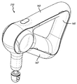
도 11은 다른 퍼커시브 마사지 디바이스의 사시도이다.
도 12는 도 11의 퍼커시브 마사지 디바이스의 측면 입면도이다.
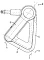
도 13은 몇몇 내부 구성요소를 은선으로 도시하고 있는 퍼커시브 마사지 디바이스의 측면 입면도이다.
도 14는 퍼커시브 마사지 디바이스의 몇몇 내부 구성요소의 분해 사시도이다.
도 15는 다른 퍼커시브 마사지 디바이스의 사시도이다.
도 16은 도 15의 퍼커시브 마사지 디바이스의 측면 입면도이다.
도 17은 힘 측정기를 갖는 퍼커시브 마사지 디바이스의 상호 연결된 구성요소를 도시하고 있는 블록도이다.
도 18은 일 실시예에 따른 핀 출력을 갖는 마이크로제어기 유닛의 회로도이다.
도 19는 일 실시예에 따른 배터리 전압 검출에 사용되는 회로도이다.
도 20은 일 실시예에 따른 퍼커시브 마사지 디바이스의 모터 전압 검출 및 측정을 위한 회로도이다.
도 21은 바람직한 실시예에 따른 퍼커시브 마사지 디바이스에 의해 인가되는 힘을 검출하는 방법을 도시하고 있는 흐름도이다.
도 22는 바람직한 실시예에 따라 전압을 힘에 상관시키는 참조표를 생성하는 방법을 도시하는 흐름도이다.
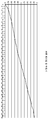
도 23은 바람직한 실시예에 따라 전압을 힘에 상관시킴으로써 생성된 퍼커시브 마사지 디바이스에 의해 인가된 힘을 검출하는 방법에 사용하기 위한 참조표를 플롯팅한 그래프이다.
도 24는 바람직한 실시예에 따른 참조표를 교정하는 방법을 도시하는 흐름도이다.
도 25는 본 발명의 바람직한 실시예에 따른 참조표를 교정하는 방법을 사용하여 교정된 참조표에 대해 퍼커시브 마사지 디바이스에 의해 인가되는 힘을 검출하는 방법에 의해 생성된 참조표를 플롯팅한 그래프이다.
도 26은 참조표를 교정하는 방법을 도시하는 흐름도이다.
도 27은 바람직한 실시예에 따라 교정된 이후의 참조표를 플롯팅한 그래프이다.
도 28은 바람직한 실시예에 따른 퍼커시브 마사지 디바이스에 의해 인가되는 힘을 검출하는 방법을 도시하고 있는 흐름도이다.
도 29는 바람직한 실시예에 따라 전력을 힘에 상관시키는 참조표를 생성하는 방법을 도시하는 흐름도이다.
도 30은 바람직한 실시예에 따라 전력을 힘에 상관시킴으로써 생성된 힘을 검출하는 방법에 사용하기 위한 참조표를 플롯팅한 그래프이다.
도 31은 바람직한 실시예에 따른 참조표를 교정하는 방법을 도시하는 흐름도이다.
도 32는 바람직한 실시예에 따라 교정된 이후의 참조표를 플롯팅한 그래프이다.
도 33은 본 발명의 바람직한 실시예에 따른 퍼커시브 마사지 디바이스의 사시도이다.
도 34는 하우징의 일부가 제거된 도 13의 퍼커시브 마사지 디바이스의 사시도이다.
도 35는 모터의 사시도이다.
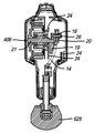
도 36은 본 발명의 바람직한 실시예에 따른 퍼커시브 마사지 디바이스의 측면 입면도이다.
도 37은 퍼커시브 마사지 디바이스의 다른 측면 입면도이다.
도 38은 사용자가 제1 핸들부를 파지하고 있는 것을 도시하고 있는 퍼커시브 마사지 디바이스의 측면 입면도이다.
도 39는 사용자가 제3 핸들부를 파지하고 있는 것을 도시하고 있는 퍼커시브 마사지 디바이스의 측면 입면도이다.
도 40은 사용자가 제2 핸들부를 파지하고 있는 것을 도시하고 있는 퍼커시브 마사지 디바이스의 측면 입면도이다.
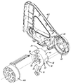
도 41은 하우징의 일부가 제거된 도 18의 퍼커시브 마사지 디바이스의 사시도이다.
도 42a 및 도 42b는 헤드부 및 모터의 단면도이다.
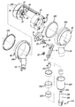
도 43은 도 33의 퍼커시브 마사지 디바이스의 몇몇 내부 구성요소의 분해도이다.
도 43a는 모터 및 모터 장착부의 분해도이다.
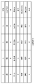
도 44는 퍼커시브 마사지 디바이스의 루틴을 수행하는 방법에 따른 프로토콜 1의 단계를 도시하는 차트이다.
도 45는 퍼커시브 마사지 디바이스의 루틴을 수행하는 방법에 따른 "정강이 통증(Shin Splints)" 프로토콜의 단계를 도시하는 차트이다.
도 46a, 도 46b, 도 46c 및 도 46d는 퍼커시브 마사지 디바이스의 루틴을 수행하는 방법이다.
도 47은 "거북목" 프로토콜을 보여주는 그래픽 사용자 인터페이스의 정면도이다. 및
도 48은 "우측 이두근" 프로토콜을 보여주는 그래픽 사용자 인터페이스의 정면도이다.
유사한 번호는 도면들의 여러 도면 전체에 걸쳐 유사한 부분을 지칭한다.BRIEF DESCRIPTION OF THE DRAWINGS The present invention may be understood more readily with reference to the accompanying drawings:
1 is a side elevational view of a percussive massage device according to a preferred embodiment of the present invention.
1A is another side elevational view of the percussive massage device of FIG. 1 ;
2 is a perspective view of a percussive massage device;
3 is a side elevational view of the percussive massage device showing the user gripping the first handle portion;
4 is a side elevational view of the percussive massage device showing the user gripping the third handle portion;
5 is a side elevational view of the percussive massage device showing the user gripping the second handle portion;
6 is an exploded perspective view of the percussive massage device.
7 is an exploded perspective view of a portion of a drive train component of the percussive massage device;
8 is another exploded perspective view of a portion of a percussive massage device;
9 is a perspective view of drive train components of the percussive massage device;
10 is a perspective view of a push rod assembly of a percussive massage device;
11 is a perspective view of another percussive massage device.
12 is a side elevational view of the percussive massage device of FIG. 11 ;
13 is a side elevational view of the percussive massage device showing some internal components in hidden lines;
14 is an exploded perspective view of some internal components of the percussive massage device;
15 is a perspective view of another percussive massage device.
16 is a side elevational view of the percussive massage device of FIG. 15 ;
17 is a block diagram illustrating interconnected components of a percussive massage device with a force meter;
18 is a circuit diagram of a microcontroller unit with a pinout according to one embodiment.
19 is a circuit diagram used to detect a battery voltage according to an exemplary embodiment.
20 is a circuit diagram for detecting and measuring a motor voltage of a percussive massage device according to an embodiment.
21 is a flowchart illustrating a method of detecting a force applied by a percussive massage device according to a preferred embodiment.
22 is a flow chart illustrating a method of generating a lookup table correlating voltage to force according to a preferred embodiment.
23 is a graph plotting a look-up table for use in a method of detecting a force applied by a percussive massage device generated by correlating a voltage to a force according to a preferred embodiment;
Fig. 24 is a flowchart illustrating a method of calibrating a lookup table according to a preferred embodiment.
25 is a graph plotting a look-up table generated by a method of detecting a force applied by a percussive massage device against a look-up table calibrated using the method for calibrating a look-up table according to a preferred embodiment of the present invention; to be.
26 is a flowchart illustrating a method of calibrating a lookup table.
27 is a graph plotting a lookup table after calibration according to a preferred embodiment.
28 is a flowchart illustrating a method of detecting a force applied by a percussive massage device according to a preferred embodiment.
29 is a flow chart illustrating a method of generating a lookup table correlating power to force according to a preferred embodiment.
30 is a graph plotting a lookup table for use in a method of detecting a force generated by correlating power to a force according to a preferred embodiment.
Fig. 31 is a flowchart illustrating a method of calibrating a lookup table according to a preferred embodiment.
32 is a graph plotting a lookup table after calibration according to a preferred embodiment.
33 is a perspective view of a percussive massage device according to a preferred embodiment of the present invention.
Fig. 34 is a perspective view of the percussive massage device of Fig. 13 with a portion of the housing removed;
35 is a perspective view of a motor;
36 is a side elevational view of a percussive massage device according to a preferred embodiment of the present invention.
37 is another side elevational view of the percussive massage device;
38 is a side elevational view of the percussive massage device showing the user gripping the first handle portion;
39 is a side elevational view of the percussive massage device showing the user gripping the third handle portion;
40 is a side elevational view of the percussive massage device showing the user gripping the second handle portion;
Fig. 41 is a perspective view of the percussive massage device of Fig. 18 with a portion of the housing removed;
42A and 42B are cross-sectional views of the head part and the motor.
Fig. 43 is an exploded view of some internal components of the percussive massage device of Fig. 33;
43A is an exploded view of a motor and a motor mounting part;
44 is a chart showing the steps of
45 is a chart showing the steps of the "Shin Splints" protocol according to a method of performing a routine of a percussive massage device.
46A, 46B, 46C and 46D are a method of performing a routine of a percussive massage device.
47 is a front view of a graphical user interface showing the "Turtleneck" protocol. and
48 is a front view of a graphical user interface showing the “Right Biceps” protocol.
Like numbers refer to like parts throughout the various figures of the drawings.
이하의 설명 및 도면은 예시적인 것이며 한정으로서 해석되어서는 안된다. 수많은 특정 세부 사항이 본 개시내용의 철저한 이해를 제공하기 위해 설명된다. 그러나, 특정 경우에는 설명을 모호하게 하는 것을 피하기 위해 잘 알려진 또는 통상적인 세부 사항은 설명하지 않는다. 본 개시내용에서 하나 또는 다른 실시예의 참조는 동일한 실시예의 참조일 수 있지만, 반드시 그러한 것은 아니고, 이러한 참조는 실시예 중 적어도 하나를 의미한다.The following description and drawings are illustrative and should not be construed as limiting. Numerous specific details are set forth in order to provide a thorough understanding of the present disclosure. In certain instances, however, well-known or customary details are not described in order to avoid obscuring the description. Reference to one or another embodiment in the present disclosure may, but is not necessarily to, a reference to the same embodiment, and such reference means at least one of the embodiments.
본 명세서에서 "일 실시예" 또는 "실시예"의 참조는 실시예와 관련하여 설명된 특정 특징, 구조 또는 특성이 본 개시내용의 적어도 하나의 실시예에 포함된다는 것을 의미한다. 명세서의 다양한 장소에서 문구 "일 실시예에서"의 출현은 반드시 동일한 실시예를 지칭하는 것은 아니고, 또한 다른 실시예와 상호 배타적인 별개의 또는 대안 실시예도 아니다. 더욱이, 몇몇 실시예에서 나타날 수도 있고 다른 실시예에서는 나타나지 않을 수도 있는 다양한 특징이 설명된다. 유사하게, 몇몇 실시예에 대한 요구 사항일 수도 있지만 다른 실시예에 대해서는 아닐 수도 있는 다양한 요구 사항이 설명된다.Reference in this specification to “one embodiment” or “an embodiment” means that a particular feature, structure, or characteristic described in connection with the embodiment is included in at least one embodiment of the present disclosure. The appearances of the phrase "in one embodiment" in various places in the specification are not necessarily referring to the same embodiment, nor is it a separate or alternative embodiment mutually exclusive of another embodiment. Moreover, various features that may appear in some embodiments and may not appear in other embodiments are described. Similarly, various requirements are described that may be requirements for some embodiments but not for other embodiments.
본 명세서에서 사용되는 용어는 일반적으로 본 개시내용의 맥락 내에서, 그리고 각각의 용어가 사용되는 특정 맥락에서 본 기술분야에서 그 일반적인 의미를 갖는다. 개시내용을 설명하는 데 사용되는 특정 용어는 본 개시내용의 설명과 관련하여 통상의 기술자에게 추가적인 지침을 제공하기 위해, 아래에 또는 명세서의 다른 곳에서 설명된다. 편의상, 특정 용어는 예를 들어 이탤릭체 및/또는 인용 부호를 사용하여 강조될 수도 있으며: 강조의 사용은 용어의 범주와 의미에 영향을 미치지 않으며; 용어의 범주와 의미는 강조되건 아니건간에 동일한 맥락에서 동일하다. 동일한 것이 하나 초과의 방식으로 일컬어질 수 있다는 것이 이해될 수 있을 것이다.Terms used herein generally have their ordinary meanings in the art within the context of the present disclosure, and in the specific context in which each term is used. Certain terms used to describe the disclosure are set forth below or elsewhere in the specification to provide additional guidance to those skilled in the art in connection with the description of the disclosure. For convenience, certain terms may be emphasized, for example, using italics and/or quotation marks: the use of emphasis does not affect the scope and meaning of the term; The categories and meanings of terms are the same in the same context, whether emphasized or not. It will be appreciated that the same may be referred to in more than one manner.
결과적으로, 대안적인 언어 및 동의어가 본 명세서에서 설명된 용어들 중 어느 하나 이상에 대해 사용될 수도 있다. 용어가 본 명세서에 상세히 설명되거나 논의되는지 아닌지 여부에 어떠한 임의의 특정 중요성도 부여되지 않는다. 특정 용어에 대한 동의어가 제공된다. 하나 이상의 동의어의 상술은 다른 동의어의 사용을 배제하지 않는다. 본 명세서에서 설명된 임의의 용어의 예를 포함하여 본 명세서의 임의의 장소에서 예의 사용은 단지 예시일 뿐이고, 본 개시내용 또는 임의의 예시된 용어의 범주 및 의미를 추가로 한정하도록 의도된 것이 아니다. 마찬가지로, 본 개시내용은 본 명세서에서 주어진 다양한 실시예에 한정되지 않는다.Consequently, alternative language and synonyms may be used for any one or more of the terms described herein. No particular importance is attached to whether a term is detailed or discussed herein. Synonyms for specific terms are provided. The specification of one or more synonyms does not exclude the use of other synonyms. The use of an example anywhere in this specification, including an example of any term described herein, is illustrative only and is not intended to further limit the scope and meaning of the disclosure or of any illustrated term. . Likewise, the present disclosure is not limited to the various embodiments given herein.
본 개시내용의 범주를 추가로 한정하려는 의도 없이, 본 개시내용의 실시예에 따른 기구, 장치, 방법 및 이들의 관련된 결과의 예가 아래에 주어진다. 제목 또는 부제가 독자의 편의를 위해 예에서 사용될 수도 있는데, 이는 본 개시내용의 범주를 결코 한정하지 않는다는 것을 주목한다. 달리 정의되지 않으면, 본 명세서에서 사용된 모든 기술 용어 및 과학 용어는 본 개시내용이 속하는 기술분야의 통상의 기술자가 통상적으로 이해하는 것과 동일한 의미를 갖는다. 상충의 경우에, 정의를 포함하여 본 문서가 우선할 것이다.Without intending to further limit the scope of the present disclosure, examples of instruments, devices, methods and their related results according to embodiments of the present disclosure are given below. It is noted that titles or subtitles may be used in the examples for the convenience of the reader, which in no way limit the scope of the present disclosure. Unless defined otherwise, all technical and scientific terms used herein have the same meaning as commonly understood by one of ordinary skill in the art to which this disclosure belongs. In case of conflict, this document, including definitions, will control.
본 명세서에 사용되는 "전방", "후방", "상부", "저부", "측면", "짧은", "긴", "상", "하" 및 "아래"와 같은 용어는 단지 설명의 용이성을 위한 것이고, 도면에 도시되어 있는 바와 같은 구성요소의 배향을 참조한다는 것이 이해될 수 있을 것이다. 본 명세서에 설명된 구성요소의 임의의 배향은 본 발명의 범주 내에 있다는 것이 이해되어야 한다.As used herein, terms such as “front”, “back”, “top”, “bottom”, “side”, “short”, “long”, “top”, “bottom” and “below” are for descriptive purposes only. It will be understood that for ease of operation, reference is made to the orientation of the components as shown in the drawings. It should be understood that any orientation of the components described herein is within the scope of the present invention.
많은 실시예가 본 명세서에 설명되지만, 설명된 실시예 중 적어도 일부는 왕복 치료 디바이스를 위한 장치, 시스템 및 방법을 제공한다.While many embodiments are described herein, at least some of the described embodiments provide apparatus, systems, and methods for reciprocating treatment devices.
도 1 내지 도 10은 충전식 배터리(및 교체형 또는 탈착형 배터리)(114)를 포함하는 퍼커시브 마사지 디바이스(212)의 실시예를 도시하고 있다. 디바이스(212)는 상업적으로 G3PRO라 칭한다. 도 1 내지 도 1a에 도시되어 있는 바와 같이, 바람직한 실시예에서, 퍼커시브 마사지 디바이스(212)는 중앙 또는 핸들 개구(149)를 규정하기 위해 협력하는 3개의 핸들부(본 명세서에서 제1 핸들부(143), 제2 핸들부(145) 및 제3 핸들부(147)라 칭함)를 포함한다. 모든 핸들부는 사람이 디바이스를 이용하기 위해 특정 핸들부를 파지할 수 있도록 구성될만큼 충분히 길다. 상이한 핸들부를 파지하는 능력은 사람이(자신의 신체 상에 디바이스를 사용할 때) 상이한 신체 부위 상에 그리고 상이한 각도로부터 디바이스를 사용할 수 있게 하여, 따라서 3개의 핸들부 없이 가능하지 않을 수도 있는 등과 같은 신체 부위에 도달하는 능력을 제공한다.1-10 show an embodiment of a
도 1에 도시되어 있는 바와 같이, 제1 핸들부(143)는 제1 핸들부 축(A1)을 규정하고, 제2 핸들부(145)는 제2 핸들부 축(A2)을 규정하고, 제3 핸들부(147)는 제3 핸들부 축(A3)을 규정하는데, 이들 축은 삼각형을 형성하도록 협력한다. 바람직한 실시예에서, 배터리(114)는 제2 핸들부(145) 내에 수용되고 모터(106)는 제3 핸들부(147) 내에 수용된다.1 , the
도 3 내지 도 5는 다양한 핸들부를 파지하는 사용자의 손을 도시하고 있다. 제1, 제2 및 제3 핸들부의 각각의 길이는, 도 3 내지 도 5에 도시되어 있는 바와 같이, 큰 손을 갖는 사람이 핸들 개구를 통해 연장하는 적어도 3개 내지 4개의 손가락으로 각각의 핸들부를 편안하게 파지할 수 있도록 충분히 길다. 바람직한 실시예에서, 제1 핸들부(143)는 내부 에지(143a)를 갖고, 제2 핸들부(145)는 내부 에지(145a)를 갖고, 제3 핸들부(147)는 내부 에지(147a)를 갖는데, 이들 에지는 모두 핸들 개구(149)를 적어도 부분적으로 규정하도록 협력한다. 도 1에 도시되어 있는 바와 같이, 바람직한 실시예에서, 제1 핸들부(143)는 제1 핸들부의 내부 에지(143a)와 제3 핸들부(147)의 내부 에지(147a) 사이에서 연장하고 핸들 개구(149)를 적어도 부분적으로 규정하는 손가락 표면(151a)을 포함하는 손가락 돌기(151)를 포함한다. 도 3에 도시되어 있는 바와 같이, 사용시에, 사용자는 자신의 검지 손가락을 손가락 표면(151a)에 접하여 놓을 수 있다. 손가락 돌기 및 표면은 사용자가 자신의 검지 손가락을 표면에 접하여 놓을 때, 이것이 사용자가 디바이스를 사용하는 제어 및 편안함을 보조하도록 하는 피드백 지점 또는 지지 표면을 제공한다. 바람직한 실시예에서, 손가락 표면(151a)의 적어도 일부는 도 1에 도시되어 있는 바와 같이 직선형이다(핸들 개구(149)의 다른 "코너들"이 라운딩되는 것과 대조적임).3 to 5 illustrate a user's hand gripping various handle units. The respective lengths of the first, second and third handle portions may be such that, as shown in FIGS. 3-5 , a person with large hands may extend each handle with at least three to four fingers extending through the handle opening. Long enough to comfortably grip wealth. In a preferred embodiment, the
도 1a는 핸들 개구(149)의 내부 표면의 바람직한 치수를 도시한다. 내부 표면은 일련의 평탄하고 만곡된 표면을 포함한다는 것이 이해될 것이다. H1은 제1 핸들부(143)의 내부 에지(143a)의 치수(제1 핸들부 길이)이다. H2는 제2 핸들부(145f)의 내부 에지(145a)의 치수(제2 핸들부 길이)이다. H3은 제3 핸들부(147)의 내부 에지(147a)의 치수(제3 핸들부 길이)이다. H4는 손가락 표면(151a)의 치수(손가락 돌기 길이)이다. R1은 내부 에지(143a, 145a) 사이의 반경의 치수이고, R2는 내부 에지(145a, 147a) 사이의 반경의 치수이다. 바람직한 실시예에서, H1은 약 94 mm이고, H2는 약 66 mm이고, H3은 약 96 mm이고, H4는 약 12 mm이고, R1은 약 6.5 mm이고 R2는 약 6.5 mm이며, 이는 약 10.2 mm의 원호 길이를 제공한다. 본 명세서의 맥락에서, "약"은 5 mm 이내이다. 바람직한 실시예에서, 핸들 개구의 내부 에지의 길이는 약 289 mm이다. 핸들 개구의 내부 에지의 길이는 H1, H2, H3, H4, R1 및 R2의 임의의 조합으로, 약 260 mm 내지 약 320 mm일 수 있다. 이들 치수는 95 백분위수의 남성이 디바이스를 이용하기 위해 적어도 3개 및 바람직하게는 4개의 손가락을 핸들 개구를 통해 연장시킨 상태로 3개의 핸들부 중 임의의 것을 파지할 수 있도록 최적화된다는 것이 이해될 수 있을 것이다. 임의의 또는 모든 표면 R1 및 R2는 3개의 인접한 핸들부 중 임의의 것의 부분으로 고려될 수 있다는 것이 이해될 수 있을 것이다. 도 1 및 도 1a에 도시되어 있는 바와 같이, 손가락 표면(151a)이 직선형인 경우, 제1 핸들부 내부 표면, 제2 핸들부 내부 표면, 제3 핸들부 내부 표면 및 손가락 표면은 각각의 직선 표면 사이에 반경 또는 라운딩된 에지를 갖는 사변형을 규정하도록 협력한다.1A shows preferred dimensions of the inner surface of the
디바이스(212)는 다중 속도 설정(바람직하게는 1500 및 2400 RPM이지만, 본 명세서에 교시된 임의의 속도 또는 주파수일 수 있음)을 또한 포함한다. 더욱이, 본 기술분야의 통상의 기술자는 RPM이 특정 숫자로서 열거되어 있지만, 제조 공차로 인해 RPM이 사용 중에 변동할 수도 있다는 것을 이해할 수 있을 것이다. 예를 들어, 2400 RPM 설정에서, RPM은 실제로 2260 내지 2640으로 변동할 수도 있다.
도 6 내지 도 10은 도 1 내지 도 5 및 도 11 내지 도 16에 도시되어 있는 치료 디바이스(212)(208, 210)에 포함된 몇몇 내부 및 외부 구성요소를 도시하고 있다. 도 6에 도시되어 있는 바와 같이, 퍼커시브 마사지 디바이스(212)는 제1 및 제2 하우징 반부(103)로 구성된 하우징(101)을 포함한다. 외부 커버(213) 및 상부 커버(215)는 탭(105) 또는 다른 메커니즘 또는 부착 방법(예를 들어, 나사형 체결구, 클립, 접착제, 음파 용접 등)을 통해 제1 및 제2 하우징 반부(103) 상에 수용되고 연결된다. 퍼커시브 마사지 디바이스(212)는 탬버 도어(217), 배터리(114), 내부 서스펜션 링(219) 및 기어박스(404)를 수용하는 회전 하우징(44)(제1 및 제2 회전 하우징 반부(44a, 44b)를 포함함)를 또한 포함한다.6-10 illustrate some of the internal and external components included in the treatment device 212 (208, 210) shown in FIGS. 1-5 and 11-16. As shown in FIG. 6 , the
도 7에 도시되어 있는 바와 같이, 디바이스는 모터와 피니언 샤프트 또는 샤프트 기어(117)(샤프트 또는 피니언 샤프트(116) 상에 위치됨) 사이에 배치된 피니언 커플링 조립체(216)를 포함한다. 피니언 커플링 조립체(216)는, 토크가 완전히 전달되어 반경방향 이동이 없고 진동 및 소음이 최소화되도록 모터를 기어박스에 결합하는 데 사용된다. 피니언 커플링 조립체(216)는 바람직하게는 3개의 개별 구성요소, 즉 하부 커넥터(218), 크로스 커플링(220) 및 상부 커넥터(222)를 포함한다. 바람직한 실시예에서, 하부 커넥터(218)는 모터 샤프트(248)를 수용하는 중앙 개구(218b)를 규정하는 본체부(218a) 및 본체부(218a)로부터 외향으로 연장하는 제1 및 제2 하부 커넥터 아암(218c)을 포함한다. 상부 커넥터(222)는 피니언 샤프트(117)를 수용하는 중앙 개구(222b)를 규정하는 본체부(222a) 및 본체부(222a)로부터 외향으로 연장하는 제1 및 제2 상부 커넥터 아암(222c)을 포함한다. 바람직하게는, 크로스 커플링(220)은 그 사이에 채널(220b)을 규정하는 반경방향 연장 리브(220a)를 포함한다. 제1 및 제2 하부 커넥터 아암(218c) 및 제1 및 제2 상부 커넥터 아암(222c)은 반경방향 연장 리브와 동작 가능하게 맞물리게 채널(220b) 내에 수용되도록 크기 설정되고 성형된다. 사용시, 모터 샤프트(248)는 피니언 커플링 조립체를 회전시키고, 이는 피니언 샤프트(117)를 회전시킨다. 이들 구성요소는 함께 작동하여 소음과 진동을 감소시킨다. 바람직한 실시예에서, 하부 및 상부 커넥터는 플라스틱으로 제조되고 크로스 커플링은 엘라스토머로 제조된다. 바람직한 실시예에서, 크로스 커플링(220)은 강도를 유지하고 토크를 효율적으로 전달하면서(상당한 에너지 소산 없이) 모터에 의해 발생된 진동이 격리되는 경도를 포함하는 고무로 제조된다. 그러나, 재료는 본 발명을 한정하지 않는다.As shown in FIG. 7 , the device includes a
바람직한 실시예에서, 피니언 샤프트(116)는 베어링(224, 225) 내에 수용되고 이들을 통해 연장한다. 바람직하게는, 베어링(224)은 볼 베어링을 포함하고(그리고 반경방향 지지를 제공함) 베어링(225)은 니들 베어링을 포함한다(그리고 반경방향 지지를 제공하지만 더 높은 온도를 견딜 수 있음). 피니언 커플링 조립체(216)는, 모터(106)에 연결되고 모터 샤프트(248)가 그를 통해 연장하는 모터 장착부(250) 내에 수용된다. 모터 장착부(250)는 도 9에 도시되어 있는 바와 같이, 기어박스 장착부(252)에 연결된다.In the preferred embodiment, the
도 7 내지 도 9에 도시되어 있는 바와 같이, 기어박스(404)는 일 실시예에서, 기어 부재(304) 및 왕복기 또는 푸시 로드(230/310)를 포함한다. 바람직하게는, 기어 부재(304)는 그로부터 연장하는 샤프트(246)를 포함하고, 이에 왕복기(310)가 연결된다. 기어박스(404)는 기어 부재(304) 및 왕복기(310)를 위한 장착점을 제공할 수도 있다. 기어박스(404)는 기어 부재(304) 및 왕복기의 운동을 특정 방향 또는 회전축으로 제한할 수도 있다. 기어박스(404)는 하우징(101)에 장착될 수도 있다. 몇몇 실시예에서, 기어박스(404)는 하나 이상의 유연성 감쇠 블록(402)에 의해 하우징(101)으로부터 분리된다.7-9 ,
도 6 및 도 8에 도시되어 있는 바와 같이, 바람직한 실시예에서, 기어박스가 하우징으로 진동을 전달하는 것을 방지하기 위해 고무 커버가 제공될 수 있다. 추가 내부 서스펜션 링(219)이 핸들 및 치료 구조체로부터 기어박스의 진동을 격리시킨다. 바람직하게는, 링(219)은 엘라스토머로 제조되고 회전 하우징과 하우징(101) 사이의 진동을 감쇠하기 위한 쿠션으로서 작용한다. 바람직한 실시예에서, 내부 서스펜션 링(219)은 본체부(62)의 외부 반경방향 표면(도 8의 안착 표면(523) 참조)을 둘러싼다.6 and 8 , in a preferred embodiment a rubber cover may be provided to prevent the gearbox from transmitting vibrations to the housing. An additional
일 실시예에서, 피동 출력부 또는 샤프트(108)의 회전은 사용자에 의해 선택적으로 로킹 및 로킹 해제될 수도 있다. 예를 들어, 사용자는 샤프트(108)의 회전을 로킹 해제하고, 피동 출력부(108)를 하우징(101)에 대해 원하는 위치로 회전시키고, 피동 출력부(108)의 회전을 로킹하고, 왕복 치료 디바이스(100)를 동작시킬 수도 있다. 도 8은 푸시 로드 조립체(108) 및 관련 구성요소와 함께 회전 하우징(44)의 회전을 허용하는 구성요소를 도시하고 있다. 버튼(515)은 반경방향 연장 치형부(515a)를 포함하고 스페이서(518)(바람직하게는 발포체로 제조됨)를 둘러싸고 그 위에 안착되는 스프링(519)에 의해 외향으로 편향된다. 스프링(519)은 바람직하게는 스프링(519)의 임의의 진동을 감쇠시키기 위해 고무로 제조되는 감쇠 부재(520, 517)에 대해 안착된다. 조립체는 기어박스 커버(525) 및 감쇠 링(521)을 또한 포함한다. 버튼(515)은 치형부(515a)가 하우징(101)에 연결된, 후프(516)에 규정되어 있는 치형부(516a)와 맞물리는 위치로 스프링(519)에 의해 외향으로 편향된다. 바람직하게는 후프(516)는 진동을 감쇠시키고 소음을 감소시키는 것을 돕기 위해 그 사이에 고무 링(516d)이 개재되어 있는 내부 및 외부 플라스틱 링(516b, 516c)을 포함한다. 버튼(515)은 치형부(515a)가 치형부(516a)와 맞물리는 제1 위치와 치형부(515)가 치형부(516a)와 맞물리지 않는 제2 위치 사이에서 이동 가능하다. 버튼(515)이 제1 위치에 있을 때, 회전 조립체(47)는 회전할 수 없다. 버튼이 제2 위치로 눌러질 때, 치형부(515a)는 치형부(516a)로부터 분리되고, 이에 의해 전체 회전 조립체(47)가 회전하게 한다. 회전 하우징(44)은 하우징 내에 배치된 본체부(62)와 회전 공간(60)을 통해 하우징 외부로 연장하는 아암부(64)를 포함한다. 아암부(64)는 하우징(101)에 규정된 회전 공간(60) 내에서 회전한다. 도 2에 도시되어 있는 바와 같이, 바람직한 실시예에서, 디바이스(212)는 회전 조립체가 도 1에 도시되어 있는 위치로부터 도 2에 도시되어 있는 위치로 이동될 때 회전 공간(60) 내에서 펼쳐지는 탬버 도어(217)를 포함한다. 탬버 도어(217)는 슬롯(214)을 커버한다. 도 2에 도시되어 있는 바와 같이, 아암 커버(524)는 회전 하우징(44)의 아암부(64)를 커버한다.In one embodiment, rotation of the driven output or
도 9에 도시되어 있는 바와 같이, 기어박스 하우징(404)은 푸시 로드 조립체(108)를 위해 그 내부에 규정된 간극 슬롯(214)을 포함한다. 슬롯(214)은 푸시 로드 조립체(108)가 자유롭게 이동하고 회전 하우징(44)이 굴절이 되게 할 수 있도록 제공된다. 간극 슬롯(214)은 제1 및 제2 단부(214a, 214b)를 갖는다. 도 9에 도시되어 있는 바와 같이, 푸시 로드 조립체(108)는 간극 슬롯(214)을 통해 연장된다. 회전 하우징(44)이 제1 위치로부터 제2 위치로 회전될 때, 푸시 로드 조립체(108)는 그 제1 단부로부터 제2 단부로 간극 슬롯(214) 내에서 이동한다는 것이 이해될 수 있을 것이다.As shown in FIG. 9 , the
도 8 내지 도 10에 도시되어 있는 바와 같이, 바람직한 실시예에서, 푸시 로드 조립체 또는 출력 샤프트(108)는 소음 및 진동을 감소시키는 것을 또한 돕기 위해 그 사이에 어댑터 부재(226)를 갖는 2개의 반부 또는 로드를 포함한다. 어댑터 부재(226)는 기어박스 내에서 발생된 진동을 격리하고 진동이 샤프트 아래로 치료 구조체로 전달되는 것을 방지한다. 어댑터 부재(226)는 사용 중에 사용자 인가된 토크로부터 푸시 로드를 보호하기 위해 회전 방지 탭을 포함할 수 있다. 출력 샤프트(108)의 제1 로드부(230)(푸시 로드 또는 왕복기(310))는 피봇 핀(234)을 수용하는 개구(232)를 그 단부에 포함한다. 제1 로드부(230)와 어댑터 부재(226) 사이의 연결부는 진동을 감쇠시키기 위해 핀(234) 및 엘라스토머 재료를 갖는 부싱(227)을 포함한다. 개구(232)를 포함하는 제1 로드부(230)의 단부는 어댑터 부재(226)의 포켓(229) 내에 수용된다. 핀(234)은 어댑터 부재(226)의 측벽의 개구를 통해, 부싱(227)을 통해, 그리고 개구(232)를 통해 연장되어 제1 로드부(230)를 어댑터 부재(226)에 고정한다. 어댑터 부재(226)는 어댑터 부재(226)를 제2 로드부(236)에 연결하기 위해 제2 로드부(236)의 단부의 개구(233) 내에 수용되는 그로부터 연장하는 돌기(231)를 포함한다. 다른 실시예에서, 제2 로드부(236)의 단부는 어댑터 부재(226)의 개구 내에 수용될 수 있다. 사용시, 포켓(229)의 상부 개구의 크기는, 개구(232)가 핀(234) 상에서 피봇하고 제1 로드부(231)가 왕복할 때 제1 로드부가 측면간으로 이동할 수 있게 한다. 이는 제2 로드부(236)의 선형 왕복으로 변환된다. 부싱(227)은 적어도 몇몇 엘라스토머 재료를 포함하기 때문에, 푸시 로드 조립체(108)가 왕복할 때 진동이 감쇠된다(그리고 소음 감소됨).8-10 , in a preferred embodiment, the push rod assembly or
링(526)은 제1 및 제2 하우징 반부(44a, 44b)를 함께 유지하는 것을 돕기 위해 아암부(64)의 저부 부분(도 8의 시트(64a) 참조)에 안착되고 둘러싼다. 와셔 또는 가이드 부재(527)가 회전 하우징(44) 내에 수용되고 왕복 푸시 로드 조립체 또는 출력 샤프트(108)를 위한 안정성 및 경로를 제공한다.A
도 9에 도시되어 있는 바와 같이, 본 실시예에서, 제1 로드부(230) 또는 푸시 로드 조립체(108)는 간극 슬롯(214)을 통해 연장된다. 용어 푸시 로드 조립체는 본 명세서에 설명된 임의의 실시예를 포함하고, 2개의 반부 사이의 피봇을 허용하는 어댑터 부재를 갖는 샤프트를 포함할 수 있고 또는 어떠한 피봇도 포함하지 않는 단일 샤프트를 포함할 수 있다는 것이 이해될 수 있을 것이다.As shown in FIG. 9 , in this embodiment, the
도 9 내지 도 10에 도시되어 있는 바와 같이, 바람직한 실시예에서, 수형 커넥터(110)는 암형 개구 내의 슬롯과 정합하는 정렬 탭(497)을 각각의 볼 위에 포함한다. 이들 탭(497)은 치료 구조체와의 적절한 정렬을 돕는다. 그대로 본 명세서에 참조로서 합체되어 있는 미국 특허 출원 공개 제2019/0017528호를 참조한다.9-10, in the preferred embodiment, the
도 11 내지 도 16은 상기 퍼커시브 마사지 디바이스(212)와 유사하지만 회전 조립체가 없는 퍼커시브 마사지 디바이스의 실시예를 도시하고 있다. 도 11 내지 도 14에 도시되어 있는 디바이스(208)는 상업적으로 G3라 칭한다. 도 15 및 도 16에 도시되어 있는 디바이스(210)는 상업적으로 LIV라 칭한다. 도 13에 도시되어 있는 바와 같이, 바람직한 실시예에서, 스위치(104)는 그와 연관된 스위치 전자 기기(575)를 포함한다. 스위치 전자 기기(575)는 인쇄 회로 기판(PCB) 및 다른 작업들 중에서도, 스위치(104)가 모터(106)를 활성화하고 모터의 속도를 변경하고 디바이스를 턴온 및 턴오프하게 하기 위한 다른 구성요소를 포함할 수도 있다. 도 13에 도시되어 있는 바와 같이, 바람직한 실시예에서, 모터(106)는 제3 핸들부(147) 내에 수용되고, 배터리(114)는 제2 핸들부(145) 내에 수용되고, 스위치 전자 기기(575)는 제1 핸들부(143) 내에 수용된다. 이 구성은 디바이스(210, 212)에도 또한 적용된다. 도 14는 기어박스(404)를 둘러싸고 기어박스 내의 구성요소에 의해 발생된 소음 및 진동을 감쇠 및 감소시키는 것을 돕는 쿠션 부재(577)를 도시하고 있다. 쿠션 부재(577)는 디바이스(212) 내의 내부 서스펜션 링(219)과 유사하다. 그러나, 쿠션 부재(577)는 더 두껍고 디바이스(208, 210)에서 회전 하우징의 배제로 인해 회전할 필요가 없다. 쿠션 부재(577)는 푸시 로드 조립체 및 피니언 샤프트와 같은 구성요소의 간극을 허용하기 위해 그 내부에 절결부 또는 채널(579)을 포함한다.11-16 show an embodiment of a percussive massage device similar to the
도 17 내지 도 35는 힘 측정기를 구비한 퍼커션 마사지 디바이스에 따른 실시예를 도시한다. 도 17은 힘 측정기(700)를 구비한 퍼커시브 테라피 디바이스의 상호 연결된 구성요소를 도시하고 있는 블록도이다. 일 실시예에서, 힘 측정기를 구비한 퍼커시브 테라피 디바이스(700)는 마이크로제어기 유닛(701), 배터리 팩 관리 유닛(702), NTC 센서(703), 전력 충전 관리 유닛(704), 무선 충전 관리 유닛(705), 무선 충전 수신 시스템(706), 전압 관리 유닛(707)(도면의 5V 3.3V 전압 관리), 배터리 충전 입력부(708)(도면의 20V 2.25A 충전 입력부), 디스플레이(709)(도면의 힘/배터리/속도 디스플레이), 무선 제어 유닛(710)(도면에서 블루투스 제어부), OLED 스크린(711), OLED 스크린 제어 시스템(712), 모터(713), 모터 구동 시스템(714), PWM 속도 설정 유닛(715), 과전류 보호 유닛(716) 및 전원 스위치 유닛(717)(도면에서 전원 온/오프 OLED 스크린 SW)을 포함한다. 도 17에 따라 도시된 실시예에서, 도면의 각각의 블록은 별개의 구성요소로 도시된다. 그러나, 대안 실시예에서, 특정 구성요소는 본 개시내용의 범위를 벗어나지 않고 조합될 수도 있다.17 to 35 show an embodiment according to a percussion massage device with a force meter. 17 is a block diagram illustrating interconnected components of a percussive therapy device having a force meter 700 . In one embodiment, percussive therapy device 700 with force meter includes
일 실시예에서, 마이크로제어기 유닛(701)은 프로세서, 메모리, 및 입력/출력 주변기기를 포함하는 마이크로제어기 유닛이다. 그러나, 다른 실시예에서 마이크로제어기 유닛(701)은 ST 마이크로일렉트로닉스 STM32F030K6 시리즈 마이크로제어기 유닛, STM32F030C8T6 시리즈 마이크로제어기, STM32F030CCT6 시리즈 마이크로제어기, 또는 동등한 마이크로제어기이다.In one embodiment,
통상의 기술자는 마이크로제어기 유닛(701)의 메모리가 마이크로제어기 유닛(701)의 프로세서에 의한 처리를 위한 기계 판독 가능 코드를 저장하도록 구성된다는 것을 이해할 것이다. 힘 측정기(700)를 구비한 퍼커시브 마사지 디바이스의 설계자가 소프트웨어, 펌웨어, 또는 양자 모두에서 기계 판독 가능 코드를 구현하기를 원하는 지 여부에 따라 다양한 다른 구성이 존재할 수도 있다. 일 실시예에서, 기계 판독 가능 코드는 메모리에 저장되고 마이크로제어기(701)의 프로세서에 의해 실행되도록 구성된다. 일 실시예에서, 기계 판독 가능 코드는 컴퓨터-판독 가능 매체에 저장된다.A person skilled in the art will understand that the memory of the
일 실시예에서, 배터리 팩 관리 유닛(702)은 펌웨어 또는 소프트웨어로 구현되고 마이크로제어기 유닛(701)과 관련하여 사용되도록 구성된다. 본 실시예에서, 펌웨어 또는 소프트웨어는 메모리(도시되어 있지 않음)에 저장되고 마이크로제어기 유닛(701)에 의해 획득가능하도록 구성된다. 배터리 팩 관리 유닛(702)은 또한 다른 실시예에서 펌웨어, 소프트웨어 및 하드웨어의 조합일 수도 있다. 배터리 팩 관리 유닛(702)은 NTC 센서(703)와 결합된다. NTC 센서(703)는 배터리 팩의 온도를 감지하기 위해 배터리 팩 관리 유닛(702)에 의해 사용되는 음의 온도 계수 서미스터이다. 예를 들어, NTC 센서(703)는 B 값이 3950 +/-1%이고 저항이 10 kΩ인 서미스터이다. 다른 예에서 서미스터의 저항은 100 kΩ이다. 본 기술 분야의 통상의 기술자는 서미스터가 그 저항이 온도에 의존하는 저항기라는 것을 인식할 것이다. 그러나, 다른 실시예에서, NTC 센서(703)는 배터리 팩 관리 유닛(702)과 관련하여 사용되는 다른 유형의 온도 감지 디바이스 또는 구성요소일 수도 있다.In one embodiment, the battery
일 실시예에서, 전력 충전 관리 유닛(704)은 펌웨어 또는 소프트웨어로 구현되고 마이크로제어기 유닛(701)과 관련하여 사용되도록 구성된다. 배터리 팩 관리 유닛(702)과 유사하게, 전력 충전 관리 유닛(704) 펌웨어 또는 소프트웨어는 메모리(도시되어 있지 않음)에 저장되고 마이크로제어기 유닛(701)에 의해 획득가능하도록 구성된다. 전력 충전 관리 유닛(704)은 또한 다른 실시예에서 펌웨어, 소프트웨어 및 하드웨어의 조합일 수도 있다. 다양한 실시예에서, 전력 충전 관리 유닛(704)은 직접 연결을 통해 또는 외부 충전기를 통해, 예컨대, 재충전 가능한 배터리로 동작가능하도록 구성될 때, 배터리 팩을 충전하도록 구성된다.In one embodiment, the power
일 실시예에서, 무선 충전 관리 유닛(705)은 배터리 팩 관리 유닛(702) 및 배터리 충전 입력부(708)에 결합된다. 다른 실시예에서, 배터리 또는 배터리 팩은 예를 들어 배터리 충전 입력부(708)에 결합된 전선 또는 코드를 사용하여 배터리 또는 배터리 팩을 충전하는 것과 같은 다른 통상적인 방법론을 사용하여 충전된다.In one embodiment, the wireless
일 실시예에서, 무선 충전 수신 시스템(706)은 전력 충전 관리 유닛(704) 및 디스플레이(709)에 결합된다. 무선 충전 수신 시스템(706)은 펌웨어, 소프트웨어 및 하드웨어 중 하나 이상을 포함한다. 일 실시예에서, 무선 충전 수신 시스템(706)은 배터리 용량에 관한 정보, 충전 메트릭, 및 무선 충전에 관한 다른 정보를 수신하고, 정보를 전력 충전 관리 유닛(704)에 전달하도록 구성된다. 무선 충전 수신 시스템(706)은 바람직하게는 힘 측정기(700)로 퍼커시브 마사지 디바이스를 충전하는 데 사용되는 무선 충전 패드를 포함한다. 본 기술 분야의 통상의 기술자는 다양한 무선 충전 디바이스가 힘 측정기(700)로 퍼커시브 마사지 디바이스를 무선 충전하기 위해 이용될 수도 있음을 이해할 것이다. 일 예로, Qi 무선 충전 표준 및 관련 디바이스는 힘 측정기(700)로 퍼커시브 마사지 디바이스를 무선으로 충전하는 데 이용될 수도 있다.In one embodiment, the wireless charging
일 실시예에서, 전압 관리 유닛(707)은 마이크로제어기 유닛(701)에 의해 사용하기 위해 5볼트에서 3.3볼트로 전력을 강압하는 DC 전압 조절기이다. 전압 관리 유닛(707)은 또한 마이크로제어기 유닛(701)에 의해 사용하기 위한 3.3볼트 전력의 관리를 위한 추가 기능을 수행할 수도 있다. 일 실시예에서, 전압 관리 유닛(707)은 예를 들어 전자 부품을 사용하여 저항성 분배기를 구현하는 것과 같이 일련의 전자 부품을 사용하여 구현된다. 다른 실시예에서, 전압 관리 유닛(707)은 5볼트에서 3.3볼트로 전압을 강압하도록 설계된 독립형 전압 조절기 모듈 및/또는 디바이스이다. 본 기술 분야의 통상의 기술자는 5볼트를 3.3볼트로 강압하는 데 이용가능한 다양한 방법론 및 디바이스를 이해할 것이다.In one embodiment,
일 실시예에서, 배터리 충전 입력부(708)는 힘 측정기(700)로 퍼커시브 마사지 디바이스를 충전하기 위해 전선 또는 코드가 삽입될 수도 있는 인터페이스이다. 예를 들어, 표준화된 배럴 커넥터가 배터리 충전 입력부(708)이다. 다른 예에서, 배터리 충전 입력부(708)는 USB 커넥터이다. 다른 더 전문화된 충전 방법론에는 앞서 설명하지 않은 특정 배터리 충전 입력이 필요할 수도 있다.In one embodiment, the
디스플레이(709)는 일 실시예에서 힘 측정기(700)를 갖는 퍼커시브 마사지 디바이스에 의해 인가되는 힘의 양을 나타내는 일련의 LED를 디스플레이한다. 대안 실시예에서, 디스플레이(709)는 힘 측정기(700)를 갖는 퍼커시브 마사지 디바이스의 현재 배터리 또는 배터리 팩 충전을 나타내는 일련의 LED를 디스플레이한다. 또 다른 실시예에서, 디스플레이(709)는 힘 측정기(700)를 갖는 퍼커시브 마사지 디바이스의 현재 속도를 나타내는 일련의 LED를 디스플레이한다. 본 기술 분야의 통상의 기술자는 앞서 설명한 실시예에서 LED가 특정되었지만, 예를 들어 액정 디스플레이, OLED, CRT 디스플레이, 또는 플라즈마 디스플레이 같은 LED를 사용하지 않는 다른 실시예가 본 개시내용의 범주에 포함된다는 점을 인식할 것이다. 본 기술 분야의 통상의 기술자는 또한 배터리 또는 배터리 팩을 이용하는 실시예에서 배터리 전력 수명을 보장하기 위해 저전력 옵션을 이용하는 것이 유리할 수도 있다는 것을 이해할 것이다. 일 실시예에서, 디스플레이(709)는 128x64 픽셀 OLED 디스플레이이다.
무선 제어 유닛(710)은 무선 마이크로제어기 유닛에서 구현될 수도 있는 무선 연결 디바이스이다. 일 실시예에서, 무선 제어 유닛(710)은 블루투스를 통해 원격 디바이스에 결합하도록 구성된 블루투스 트랜시버 모듈이다. 일 실시예에서, 블루투스 모듈은 브로드캐스트 모드에서 실행되도록 구성된 BLE(Bluetooth Low-Energy) 모듈이다. 무선 제어 유닛(710)은 마이크로제어기 유닛(701)에 결합된다. 일 실시예에서, 원격 디바이스는 임베디드 블루투스 모듈을 갖는 스마트폰이다. 대안 실시예에서, 원격 디바이스는 블루투스 연결을 갖는 개인용 컴퓨터이다. 다른 실시예에서, 블루투스 무선 표준 이외의 다른 무선 연결 표준이 이용될 수도 있다. 블루투스 연결 또는 다른 무선 연결이 무선 연결 디바이스에서 구현되는 것으로 본 명세서에 설명될 수도 있다는 것이 이해될 것이다. 무선 연결 디바이스는 별개의 모듈일 수 있거나, MCU 또는 디바이스의 다른 구성요소에 포함될 수 있거나, 또는 별개의 칩일 수 있다. 요약하면, 무선 연결 디바이스를 포함하는 퍼커시브 테라피 디바이스는 퍼커시브 마사지 디바이스가 다른 전자 디바이스(예를 들어, 전화, 태블릿, 컴퓨터, 컴퓨터, 음성 제어 스피커, 일반 스피커 등)에 무선으로 연결될 수 있음을 의미한다. 본 기술 분야의 통상의 기술자는 힘 측정기(700)를 갖는 퍼커시브 마사지 디바이스가 배터리 또는 배터리 팩을 이용할 때 저전력 무선 제어 모듈이 유리할 수도 있음을 인식할 것이다.The
일 실시예에서, OLED 스크린(711) 및 OLED 스크린 제어 시스템(712)은 위에서 참조된 디스플레이(709)와 실질적으로 동일한 정보를 디스플레이하도록 구성된다. OLED 스크린(711)은 OLED 스크린 제어 시스템(511)에 결합된다. OLED 스크린 제어 시스템(712)은 마이크로제어기 유닛(701), OLED 스크린(711), 및 전원 스위치 유닛(717)에 결합된다. 일 실시예에서, 디스플레이(709) 및 OLED 스크린(711)은 중복될 수 있고, 단지 어느 한쪽만 이용하면 될 수도 있다.In one embodiment,
일 실시예에서, 모터(713)는 브러시리스 직류(BLDC) 모터이다. 일 실시예에서, 모터(713) 및 모터 구동 시스템(714)은 왕복 운동으로 변환될 수도 있는 속도(즉, 회전 운동)를 변화시키도록 구성된다. 다른 실시예에서, 모터(713)는 브러시 DC 모터, 브러시 AC 모터, 또는 브러시리스 AC 모터이다. 본 기술 분야의 통상의 기술자는 브러시리스 또는 브러시 모터, 또는 직류 또는 교류를 선택하는 것이 응용 및 의도된 크기, 배터리 전력 및 용도에 따라 달라질 수도 있음을 이해할 것이다.In one embodiment, the
일 실시예에서 PWM 속도 설정 유닛(715)은 모터(713)를 구동하는 데 이용되는 펄스 폭 변조를 제어하는 데 이용된다. PWM 속도 설정 유닛(715)은 마이크로제어기 유닛(701) 및 과전류 보호 유닛(716)에 결합된다. 본 기술 분야의 통상의 기술자는 펄스 폭 변조가 모터(713)에 인가된 평균 전력을 변화시켜 원하는 대로 변하는 속도를 야기하는 방식이라는 것을 이해할 것이다. 대안 실시예에서, 본 기술 분야의 통상의 기술자는 브러시리스 DC 모터의 속도를 변경하기 위한 다양한 방법이 있음을 이해할 것이다. 예를 들어, 모터(713)에 대한 전압은 다른 비-PWM 방법으로 제어될 수도 있다.In one embodiment, the PWM
일 실시예에서, 과전류 보호 유닛(716)은 모터에 대한 높은 전류에 의해 야기되는 손상을 방지하기 위해 통합된 시스템-인-패키지(integrated system-in-package)의 특징일 수도 있다. 다른 실시예에서, 과전류 보호 유닛(716)은 과도하게 높은 전류로부터 모터를 보호하도록 구성된 일련의 전자 부품을 사용하여 구현된다.In one embodiment, the
일 실시예에서, 전원 스위치 유닛(717)은 힘 측정기(700)를 갖는 퍼커시브 마사지 디바이스를 턴온 및 턴오프하도록 구성된다. 전원 스위치 유닛(717)은 OLED 스크린 제어 시스템(712) 및 마이크로제어기 유닛(701)에 결합된다. 일 실시예에서, 전원 스위치 유닛(717)은 스위치(405)이다.In one embodiment, the
도 18은 핀 출력을 갖는 마이크로제어기 유닛(701)의 회로도를 도시한다. 본 실시예에서는 STM32F030K6 시리즈 마이크로제어기 유닛이 이용된다. 회로도는 마이크로제어기 유닛(701)의 VDD 입력부에 제공되는 +3.3볼트 전력을 도시한다. 입력부 PA3은 모터(713)의 전압인 "Motor_VOL"로 표시된다. 입력부 PA2는 배터리 또는 배터리 팩 전압인 "bt_v"이다. 마이크로제어기 유닛은 입력부 PA2 및 PA3에서 아날로그 전압을 수신하고 마이크로제어기의 아날로그-디지털 변환기를 사용하여 이를 디지털 전압으로 변환하도록 구성된다. 본 실시예에서 아날로그-디지털 변환기는 12 비트 ADC이다. 본 기술 분야의 통상의 기술자는 다른 마이크로제어기가 전압 감지 및 아날로그-디지털 변환기를 이용하여 유사한 기능을 수행할 수도 있음을 이해할 것이다. 또 다른 실시예에서, 마이크로제어기와 별개인 아날로그-디지털 변환기 모듈이 이용될 수도 있다.18 shows a circuit diagram of a
도 19는 배터리 전압 검출에 사용되는 회로도를 도시한다. 본 실시예에서, 양극 배터리 단자(518)인 +BT는 P-채널 MOSFET(519), N-채널 MOSFET(520), 0.1 μF 커패시터(521), 100 kΩ 저항기(522, 523), 68 kΩ 저항기(524), 1 kΩ 저항기(525, 526) 및 10 kΩ 저항기(527, 528)로 구성된 회로에 결합된다. 회로는 배터리 또는 배터리 팩의 입력 아날로그 전압, 또는 bt_v를 도 18의 마이크로제어기 유닛(701)에 제공하도록 구성된다. 다른 실시예에서, 배터리 또는 배터리 팩의 전압은 배터리 또는 배터리 팩의 단자에 결합된 전압 판독기를 사용하여 달성될 수도 있다.19 shows a circuit diagram used for battery voltage detection. In this embodiment, +BT as
도 20은 퍼커시브 마사지 디바이스의 모터(713)의 전압 검출 및 측정을 위한 회로도를 도시한다. 본 실시예에서, 전압 감지 저항기(529)는 마이크로제어기 유닛(701)과 병렬로 결합되고, 모터(713)에 결합된다. 일 실시예에서, 전압 감지 저항기는 0.0025 Ω의 값을 갖는다. 도 20에 도시된 회로는 도 17의 마이크로제어기 유닛(701)에 Motor_VOL 입력을 제공하도록 구성된다. 일 실시예에서, 입력 아날로그 전압은 증폭된다. 다른 실시예에서, 모터(713)의 전압은 별개의 일련의 전자 부품 또는 독립형 디바이스를 사용하여 측정 또는 감지되고 퍼커시브 마사지 디바이스에 힘을 디스플레이하는 방법과 함께 사용하기 위해 마이크로프로세서에 입력된다.20 shows a circuit diagram for voltage detection and measurement of the
도 21은 바람직한 실시예에 따른 퍼커시브 마사지 디바이스에 의해 인가된 힘을 검출하는 방법(800)을 도시하고 있는 흐름도이다. 단계 802에서, 전압 크기 V가 획득된다. 일 실시예에서, 전압 크기(V)는 도 17에 개시된 회로를 사용하여 획득된 아날로그 전압이다. 이 회로에서, 모터(713)(즉, 홀 효과 센서)로부터의 블록 곡선 신호는 저항기 R을 사용하여 전류로서 회로에서 시뮬레이션되고, 이 저항기는 마이크로제어기 유닛(701)과 병렬로 배치된다. 다른 실시예에서, 모터(713)의 현재 동작 속도에 대응하는 전압은 다양한 다른 방식으로 생성될 수도 있다. 전압 크기 V는 STM32F030K6 마이크로제어기 유닛에 구현된 것과 같은 아날로그-디지털 변환기를 사용하여 아날로그 전압을 디지털 전압으로 변환하는 마이크로제어기 유닛(701)에 입력될 수도 있다. STM32F030K6 마이크로제어기 유닛은 아날로그 전압 크기를 12 비트 ADC(즉, 0 내지 4096)에 대응하는 디지털 코드로 변환한다. 디지털 코드는 획득한 원래 전압 크기 V에 대응하는 전압 크기를 나타낸다.21 is a flow diagram illustrating a
단계 804에서, 전압 V를 힘 크기 F와 상관시키는 참조표가 생성된다. 일 실시예에서, 참조표는 전압을 힘에 상관시키는 참조표를 생성하는 방법(900)을 사용하여 생성된다. 예를 들어, 힘 크기 F는 파운드 단위 힘으로 표현될 수도 있다. 대안 실시예에서, 힘 크기 F는 뉴턴 단위 힘으로 표현될 수도 있다.In
단계 806에서, 전압 크기 V에 대응하는 힘 크기 F가 힘 측정기(700)를 갖는 퍼커시브 마사지 디바이스에 디스플레이된다. 일 실시예에서, 힘 측정기(700)를 갖는 퍼커시브 마사지 디바이스에 의해 힘이 인가될 때 다양한 양의 힘을 나타내기 위해 일련의 LED 조명이 이용될 수도 있다. 따라서 힘 크기 F의 양이 증가함에 따라 일련의 LED 조명에서 더 많은 LED가 켜진다. 바람직하게는, 일련의 LED 조명은 12개의 LED 조명으로 구성된다.In
도 22는 전압과 힘을 상관시키는 참조표를 생성하는 방법(900)을 도시하는 흐름도이다. 단계 902에서, 힘의 최대 크기 FMAX가 결정된다. FMAX의 크기는 힘 측정기(700)를 갖는 퍼커시브 마사지 디바이스를 사용하여 인가할 최대 원하는 힘을 평가함으로써 결정될 수도 있다. 예를 들어, FMAX는 60 파운드의 힘이다.22 is a flow diagram illustrating a
단계 904에서, 전압의 최대 크기 VMAX가 결정된다. VMAX의 크기는 힘 측정기(700)를 갖는 퍼커시브 마사지 디바이스에 의해 가능한 최대 이론적 전압 변화를 평가함으로써 결정될 수도 있다. 예를 들어, VMAX는 1.8 볼트이다.At
단계 906에서, FMAX는 동일한 증분으로 나누어진다. 단계 902의 위 예를 사용하여 60 파운드의 힘이 60개의 1 파운드 증분으로 나누어진다.In
단계 908에서, VMAX는 위의 단계 906에서 결정된 것과 동일한 양의 증분으로 나누어진다. 따라서, 단계 904의 위 예를 사용하여 1.8 볼트는 60개의 0.3 볼트 증분으로 나누어진다.In
단계 910에서, 파운드 단위 힘의 증분을 전압의 증분과 상관시키는 참조표(LUT)가 생성된다. 이는 필연적으로 힘과 전압 사이에 선형 관계를 생성한다. 도 23은 도 22에서 식별된 특정 예를 사용하여 생성된 도 21의 힘 검출 방법에서 사용하기 위한 LUT를 플롯팅한 그래프이다. 그래프는 방법(900)을 사용하여 계산된 계산된 힘을 도시한다.At
방법(900)의 단계 904에서의 이론적 최대 전압 가정이 부정확하다는 문제가 발생할 수도 있다. 힘 측정기(700)를 갖는 퍼커시브 마사지 디바이스가 사용될 때, 최대 가용 전압이 시간 경과에 따라 저하되는 경우가 또한 있을 수도 있다. 즉, 배터리 또는 배터리 팩 전압이 감소될 수도 있다.A problem may arise that the theoretical maximum voltage assumption in
따라서, 방법(900)에 의해 생성된 LUT를 교정하는 방법(1000)이 유리할 수도 있다. 도 24는 LUT를 교정하는 방법(1000)을 도시하고 있는 흐름도이다. 단계 1002에서, 배터리 팩 전압(BV)이 획득된다. 일 실시예에서, 배터리 팩 전압 크기(BV)는 도 19에 개시된 회로를 사용하여 획득된 아날로그 전압이다. 이 회로에서, 배터리 팩 전압 크기(BV)는 STM32F030K6 마이크로제어기 유닛에 구현된 것과 같은 아날로그-디지털 변환기를 사용하여 아날로그 전압을 디지털 전압으로 변환하는 마이크로제어기 유닛(701)에 입력될 수도 있다. STM32F030K6 마이크로제어기 유닛은 아날로그 전압 크기를 12 비트 ADC(즉, 0 내지 4096)에 대응하는 디지털 코드로 변환한다. 디지털 코드는 획득한 원래 배터리 팩 전압 크기(BV)에 대응하는 전압 크기를 나타낸다.Accordingly, the
단계 1004에서, VMAX는 실제 배터리 전압 크기(BV) 출력으로 설정된다. 예를 들어, 1.8볼트에서 1.74볼트로 0.6볼트가 감소할 수도 있다. 단계 1006에서, LUT 선형 상관은 더 낮은 VMAX를 반영하도록 조정된다. 도 25는 방법(1000)을 사용하여 교정된 LUT에 대해 방법(900)에 의해 계산된 LUT를 플롯팅한 그래프이다. 방법(1000)으로 인한 LUT는 계산된 힘이 아니라 교정된 힘을 나타낸다.At
도 26은 LUT를 교정하는 방법(1100)을 보여주는 흐름도이다. 방법(1100)은 방법(900) 이후에, 또는 방법(900)과 완전히 별개로 수행될 수도 있다. 단계 1102에서, 배터리 팩 전압(BV)이 측정된다. 일 실시예에서, 측정은 힘 측정기(700)를 갖는 퍼커시브 마사지 디바이스로부터 어떠한 힘도 인가하지 않고 행해진다. 일 실시예에서, 배터리 팩 전압(BV)은 외부 전압 측정기를 사용하여 측정된다. 다른 실시예에서, 배터리 팩 및/또는 마이크로제어기 유닛(701)은 배터리 팩 전압(BV)을 직접 측정하기 위한 내장된 해결책을 갖는다.26 is a flow diagram illustrating a
단계 1104에서, 측정된 배터리 팩 전압(BV)에 대응하는 힘 크기(F)를 결정하기 위해 힘 크기(F)를 디스플레이하는 힘 측정기를 구비한 퍼커시브 마사지 디바이스(700) 상의 디스플레이가 판독된다.In
단계 1106에서, 인가되는 실제 힘을 측정하기 위해 힘 측정기가 사용된다. 일 실시예에서, 힘 측정기는 푸시/풀 힘 측정기이다. 힘의 직접 측정은 디스플레이된 힘 크기 F를 측정된 실제 힘과 비교하여 LUT를 교정할 수 있게 한다. 단계 1108에서, LUT는 측정된 배터리 팩 전압(BV)에 대응하는 교정된 힘으로 업데이트된다. 단계 1108 이후에, 단계(1102-1106)는 각각의 연속적인 전압 증분에 대해 반복된다. 방법(900)에 따라 도시된 실시예에서, 단계(1102-1106)는 매 3볼트 증분마다 반복된다. 도 27은 모든 3볼트 증분이 업데이트된 후 방법(1100)에 의해 계산된 LUT를 플롯팅한 그래프이다.In
도 28은 바람직한 실시예에 따른 퍼커시브 마사지 디바이스에 의해 인가되는 힘을 검출하는 방법(1200)을 도시하고 있는 흐름도이다. 단계 1202에서, 배터리 팩의 전류 크기(C)가 획득된다. 일 실시예에서, 전류 크기(C)는 마이크로제어기 유닛(701)에 입력된다. 단계 1204에서, 배터리 팩의 전압 크기(BV)가 획득된다. 일 실시예에서, 전압 크기(BV)는 마이크로제어기 유닛(701)에 입력된다. 단계 1206에서, 전력은 C와 BV의 곱을 사용하여 계산된다. 일 실시예에서, 마이크로제어기 유닛(701)은 C와 BV를 승산하여 전력을 계산하도록 구성된다. 단계 1208에서, 전력 크기 P를 힘 크기 F와 상관시키는 참조표가 생성된다. 일 실시예에서, 참조표는 전력을 힘과 상관시키는 참조표를 생성하는 방법(1300)을 사용하여 생성된다. 예를 들어, 전력 크기 P는 와트 단위로 표현될 수도 있다. 대안 실시예에서, 힘 크기 F는 파운드 단위 힘 또는 뉴턴 단위 힘으로 표현될 수도 있다.Fig. 28 is a flow chart illustrating a
단계 1210에서, 전력 크기(P)에 대응하는 힘 크기(F)가 힘 측정기(700)를 갖는 퍼커시브 마사지 디바이스에 디스플레이된다. 일 실시예에서, 힘 측정기(700)를 갖는 퍼커시브 마사지 디바이스에 의해 힘이 인가될 때 다양한 양의 힘을 나타내기 위해 일련의 LED 조명이 이용될 수도 있다. 따라서 힘 크기 F의 양이 증가함에 따라 일련의 LED 조명에서 더 많은 LED가 켜진다. 바람직하게는, 일련의 LED 조명은 12개의 LED 조명으로 구성된다.In
도 29는 전력을 힘에 상관시키는 참조표를 생성하는 방법(1300)을 도시하고 있는 흐름도이다. 단계 1302에서, 전력의 최대 크기 FMAX가 결정된다. 그러나, 전력의 이론적 최대 크기는 총 유효 전력을 계산할 수도 있는 경우 합리적인 가정이 아니다. 수학식 1을 이용하여 총 최대 유효 전력(EPMAX)을 결정할 수도 있다.29 is a flow diagram illustrating a
수학식 1: 총 EPMAX = PMAX x 총 EPEquation 1: Total EP MAX = P MAX x Total EP
수학식 2를 이용하여 총 EP를 계산할 수도 있으며, 이는 그 후, 위의 수학식 1에 입력된다.The total EP may be calculated using
수학식 2: 총 EP = EPBATTERY x EPPCBA x EPMOTOR Equation 2: Total EP = EP BATTERY x EP PCBA x EP MOTOR
여기서, 총 EP, EPBATTERY, EPPCBA 및 EPMOTOR은 모두 백분율로 표현되며, PCBA는 인쇄 회로 기판 조립체이다.Here, the total EP, EP BATTERY , EP PCBA and EP MOTOR are all expressed as percentages, where PCBA is the printed circuit board assembly.
일 실시예에서, EP(배터리)는 85%이고, EP(PCBA)는 95%이고, EP(모터)는 75%이다. 따라서, 수학식 2를 사용하면 총 EP는 85% * 95% * 75% = 60.5625%이다.In one embodiment, the EP (battery) is 85%, the EP (PCBA) is 95%, and the EP (motor) is 75%. Therefore, using
본 실시예에서, PMAX는 수학식 3에서와 같이 배터리 팩의 최대 전압 VMAX와 최대 암페어 수 CMAX를 승산함으로써 계산된다. 그 후, PMAX가 수학식 1에 입력된다.In this embodiment, P MAX is calculated by multiplying the maximum voltage V MAX of the battery pack by the maximum number of amperes C MAX as in Equation 3 . Then, P MAX is input to Equation (1).
PMAX = VMAX x CMAX P MAX = V MAX x C MAX
본 실시예에서, VMAX는 16.8 볼트이고 CMAX는 20 암페어이다. 따라서, PMAX는 336 와트이다.In this embodiment, V MAX is 16.8 volts and C MAX is 20 amps. Therefore, P MAX is 336 watts.
이제, 수학식 1로 돌아가서, PMAX가 336 와트이고 총 EP가 60.5625%인 경우, 이때, 총 EPMAX는 203 와트이다.Now, returning to
단계 1304에서, 전력의 최소량(PMIN)이 결정된다. 어떠한 힘도 인가되지 않은(즉, 무부하) 전력이 0이 아님을 본 기술 분야의 통상의 기술자는 인식할 것이다. 따라서, 12 와트의 PMIN이 가정된다. 통상의 기술자는 또한 이 값이 부하가 없는 정격 전력과 등가이고 VMAX 및 CMIN로부터 유도될 수도 있다는 것을 이해할 것이다.At
단계 1306에서, 힘의 최대 크기 FMAX가 결정된다. FMAX의 크기는 힘 측정기(700)를 갖는 퍼커시브 마사지 디바이스를 사용하여 인가할 최대 원하는 힘을 평가함으로써 결정될 수도 있다. 예를 들어, FMAX는 60 파운드의 힘이다.At
단계 1308에서, 총 EPMAX는 동일한 증분으로 나누어진다. 일 실시예에서, 총 EPMAX는 PMIN(12 와트)에서 시작하여 1 파운드의 힘당 3 와트 증분으로 나누어진다. 본 기술 분야의 통상의 기술자는 FMAX가 60 파운드의 힘이고 힘 측정기(700)를 갖는 퍼커시브 마사지 디바이스의 총 원하는 힘 출력인 경우, 이때 60 파운드의 힘은 계산된 총 EPMAX 내에서 189 와트와 상관됨을 인식할 것이다.In
단계 1310에서, 힘의 파운드 증분을 와트 단위의 전력 증분과 상관시키는 LUT가 생성된다. 이는 필연적으로 힘과 전압 사이에 선형 관계를 생성한다. 도 30은 도 25에서 식별된 특정 예를 사용하여 생성된 도 28의 힘 검출 방법에서 사용하기 위한 LUT를 플롯팅한 그래프이다. 그래프는 방법(1200)을 사용하여 계산된 계산된 힘을 도시한다.In
방법(900)과 유사하게, 방법(1200)의 단계 1204에서 배터리 팩의 측정된 전압이 부정확하다는 문제가 발생할 수도 있다. 힘 측정기(700)를 갖는 퍼커시브 마사지 디바이스가 사용될 때, 최대 가용 전압이 시간 경과에 따라 저하되는 경우가 또한 있을 수도 있다. 즉, 배터리 또는 배터리 팩 전압이 감소될 수도 있다.Similar to
도 31은 LUT를 교정하는 방법(1400)을 보여주는 흐름도이다. 방법 1400은 방법 900 또는 방법 1200 후에 수행되거나, 방법 900 또는 방법 1200과 완전히 별개로 수행될 수도 있다. 단계 1402에서, 배터리 팩의 전류 크기(C)가 획득된다. 일 실시예에서, 전류 크기(C)는 마이크로제어기 유닛(701)에 입력된다.31 is a flow diagram illustrating a
단계 1404에서, 배터리 팩 전압(BV)이 측정된다. 일 실시예에서, 측정은 힘 측정기(700)를 갖는 퍼커시브 마사지 디바이스로부터 어떠한 힘도 인가하지 않고 행해진다. 일 실시예에서, 배터리 팩 전압(BV)은 외부 전압 측정기를 사용하여 측정된다. 다른 실시예에서, 배터리 팩 및/또는 마이크로제어기 유닛(701)은 배터리 팩 전압(BV)을 직접 측정하기 위한 내장된 해결책을 갖는다. 단계 1406에서, 전력이 C와 BV의 곱을 사용하여 계산된다. 일 실시예에서, 마이크로제어기 유닛(701)은 C와 BV를 승산하여 전력을 계산하도록 구성된다.In
단계 1408에서, 힘 크기(F)를 디스플레이하는 힘 측정기(700)를 구비한 퍼커시브 마사지 디바이스 상의 디스플레이는 계산된 전력에 대응하는 힘 크기(F)를 결정하기 위해 판독된다. 단계 1410에서, 인가되는 실제 힘을 측정하기 위해 힘 측정기가 사용된다. 일 실시예에서, 힘 측정기는 푸시/풀 힘 측정기이다. 힘의 직접 측정은 디스플레이된 힘 크기 F를 측정된 실제 힘과 비교하여 LUT를 교정할 수 있게 한다. 단계 1412에서, LUT는 측정된 전력에 대응하는 교정된 힘으로 업데이트된다. 단계 1412 이후, 각각의 전력 또는 힘 증가에 대해 단계 1402-1410이 반복된다. 방법(900)에 따라 도시된 실시예에서, 단계 1402-1410은 매 3-와트 증분에 대해 반복된다. 도 32는 모든 3 와트 증분이 업데이트된 후 방법(1400)에 의해 계산된 LUT를 플롯팅한 그래프이다.In
도 33 내지 도 35는 본 명세서, 특히 도 17 내지 도 48(또는 도 1 내지 도 16)에 개시된 특징을 구현하는 예시적인 퍼커시브 마사지 디바이스(400)를 도시한다. 일반적으로, 퍼커시브 마사지 디바이스(400)는 하우징(402), 전원 또는 배터리 팩(114), 하우징(101)에 위치된 모터(406), 및 모터(406)를 활성화하기 위한 스위치(405)를 포함한다. 전자 기기(도 34의 인쇄 회로 기판(408) 참조)는 모터의 전압을 획득하고, 퍼커시브 마사지 디바이스에 의해 인가되는 힘에 전압을 상관시키는 참조표를 생성하고, 참조표를 사용하여 획득한 전압에 대응하는 힘 크기를 디스플레이하도록 구성된 제어기를 포함한다. [5063의 끝]33-35 illustrate an exemplary
도 36 내지 도 43a는 퍼커시브 마사지 디바이스(400)의 추가 도면을 도시한다. 도 36 및 도 37은 도 1 및 도 1a와 유사하며, 퍼커시브 마사지 디바이스(400)가 핸들부(149)를 규정하도록 협력하는 제1, 제2 및 제3 핸들부(143, 145, 147)를 갖는 유사한 삼각형 형상을 포함하는 것을 도시한다. 도 36 내지 도 40에 도시된 다른 참조 번호 및 특징에 대한 설명에 대해서는 적어도 도 1 내지 도 5의 설명을 참조한다. 임의의 퍼커시브 테라피 또는 마사지 디바이스와 관련하여 앞서 설명된 모든 특징 및 구성요소가 퍼커시브 마사지 디바이스(400)에 포함될 수도 있다.36-43A show further views of the
도 41 내지 도 43에 도시되어 있는 바와 같이, 바람직한 실시예에서, 브러시리스 모터(406)가 헤드부(12)에 위치된다. 퍼커시브 마사지 디바이스(400)는 회전 하우징(44)의 일부인 회전 가능한 아암을 포함할 수 있다. 모터(406)는 회전 하우징(44)에 위치하고, 이는 하우징(101)의 헤드부(12)와 함께 수용된다. 다른 실시예에서, 회전 능력은 생략될 수 있다.41-43 , in the preferred embodiment, a
바람직한 실시예에서, 디바이스는 모터(406) 및 그로부터 연장되는 모터 샤프트(21)에 의해 회전되는 샤프트(16)에 직접 연결된 푸시 로드 또는 샤프트(14)를 포함한다. 샤프트(16)는 평형추(19)를 포함하는 평형추 조립체(17)의 일부일 수 있다. 바람직한 실시예에서, 푸시 로드(14)는 도 42a 및 도 42b에 도시되어 있는 바와 같이 L-형상이거나 원호 형상을 포함한다. 바람직하게는, 푸시 로드(14)가 샤프트(16)에 연결되는 지점은 푸시 로드(14)(및 마사지 부착물(628))의 말단 단부(18)가 이동하는 왕복 경로로부터 오프셋된다. 이 기능은 원호 또는 L-형상에 의해 제공된다. 푸시 로드(14)는 힘을 수직 대신 적어도 부분적으로 대각선으로 또는 그 형상을 따른 원호로 전달할 수 있어 모터가 디바이스의 중앙 또는 그 근방에 위치할 수 있도록 설계됨을 이해하여야 하며, 그렇지 않으면 샤프트를 중심에 유지하기 위해 큰 돌기가 필요할 것이고, 이 경우, 모터는 그로부터 오프셋된다(그리고 돌기 내에 위치된다). 원호는 또한 푸시 로드(14)가 도 42a 및 도 42b에 도시되어 있는 바와 같이 모터와 근접한 간극을 가질 수 있게 하고, 외부 하우징이 유사한 종래 기술 디바이스보다 더 작아질 수 있게 하며, 따라서, 디바이스(400)를 더 낮은 프로파일로 형성한다. 도 42a는 그 이동의 하사점에 있는 푸시 로드(14)를 도시하고 도 42b는 그 이동의 상사점에 있는 푸시 로드(14)를 도시한다. 바람직하게는, 하나 이상의 베어링(20)이 푸시 로드(14)의 기단 단부에 포함되고, 이는 모터에 연결되어 대각선 힘을 상쇄하고 푸시 로드(14)가 이동하여 모터(406)와 접촉하는 것을 방지한다. 베어링(20)은 샤프트(16)에 수용되고 나사형 체결구(26)는 샤프트(16)의 동축 개구(16a)에 수용된다. 푸시 로드(14)의 기단 단부는 베어링(20)에 수용된다. 이들 구성요소는 모두 도 43에 도시되어 있다.In a preferred embodiment, the device comprises a push rod or
도 33에 도시되어 있는 바와 같이, 바람직한 실시예에서, 디바이스(400)는 터치스크린(409)(또한, 방법 단계와 관련하여 터치스크린(1582)으로서 본 명세서에서 칭해짐) 뿐만 아니라 디바이스를 동작시키는 버튼(들)(예를 들어, 시작, 정지, 활성화, 속도 변경, 진폭 등)을 포함한다. 터치스크린(409)은 또한 다른 기능을 포함할 수 있다. 디바이스(400)는 또한 사용자가 다른 기능을 스크롤하거나 탐색할 수 있게 하기 위해 터치스크린/온오프 버튼 근방에 위치한 섬휠 또는 롤링 버튼을 포함할 수 있다. 디바이스를 동작시키기 위한 터치스크린(409). 도 33에 도시된 실시예에서, 디바이스(400)는 터치스크린(409), 디바이스를 턴온 및 턴오프하기 위한 중앙 버튼(404) 및 좌우로(예를 들어, 본 명세서에서 설명된 미리 설정된 치료로) 및 위아래로(예를 들어 속도 또는 주파수를 제어하기 위해) 스크롤하는 능력을 제공하는 링/로커 버튼(447)을 포함한다. 스크린은 또한 비-터치 스크린일 수 있거나 단지 디스플레이용으로만 사용될 수 있다.33 , in the preferred embodiment, the
다른 바람직한 실시예에서, 본 명세서에 교시된 임의의 디바이스는 진폭 또는 스트로크를 변화시키는 능력을 포함하고, 따라서 응용 또는 사용자의 필요에 따라 더 길거나 더 짧은 스트로크를 제공할 수 있다. 예를 들어, 스트로크는 약 8-16 mm 사이에서 변하거나 변경될 수 있다. 다른 실시예에서, 스트로크는 최대 25 mm 이상까지 변경될 수 있다. 진폭/스트로크 가변성은 또한 본 명세서에서 설명된 루틴, 사전 설정 또는 프로토콜의 일부일 수 있다. 예를 들어, 디바이스는 커넥터의 편심도가 수정될(예를 들어, 4 mm과 8 mm 사이) 수 있게 하는 기계적 스위치를 포함할 수 있다. 메커니즘은 푸시 버튼과 슬라이더를 포함할 수 있다. 핀 구조는 로킹 위치로 다시 물러나게 하는 스프링을 갖는다.In other preferred embodiments, any device taught herein includes the ability to vary amplitude or stroke, thus providing longer or shorter strokes depending on the needs of the application or user. For example, the stroke may vary or vary between about 8-16 mm. In other embodiments, the stroke may vary by up to 25 mm or more. Amplitude/stroke variability may also be part of a routine, preset or protocol described herein. For example, the device may include a mechanical switch that allows the eccentricity of the connector to be modified (eg, between 4 mm and 8 mm). The mechanism may include a push button and a slider. The pin structure has a spring that retracts it back into the locked position.
상기 퍼커시브 마사지 디바이스(208, 210, 212)와 유사하게, 바람직한 실시예에서, 디바이스(400)는 엘라스토머 등으로 형성되고 디바이스를 상대적으로 조용하게 유지하기 위해 진동을 감쇠하는 다수의 감쇠 구성요소를 포함한다. 예를 들어, 도 43에 도시되어 있는 바와 같이, 디바이스(400)는 감쇠 링(426)(내부 서스펜션 링(219)과 유사함)을 포함하고, 이는 회전 하우징(44)(제1 및 제2 회전 하우징 반부(44a 및 44b)를 구비함)을 둘러싸고, 회전 하우징과 외부 하우징(101) 사이의 진동 소음을 감쇠하는 것을 돕는다.Similar to the
도 43 및 도 43a에 도시되어 있는 바와 같이, 바람직하게는 디바이스(400)는 또한 모터(406)를 제자리에 고정하고, 하우징(101/402)에 고정되는 모터 장착부(24)를 포함한다. 모터(406)는 (제1 벽(38)에서) 모터 장착부(24)에 규정된 돌기 개구(32)에 수용된 3개의 돌기(30)(그리고 1개와 10개 사이의 수가 포함될 수 있음)를 갖는 수용 부재(28) 포함한다. 모터 장착부(24)로부터 연장되는 플랜지(34)는 돌출부(30)를 제자리에 유지하는 것을 돕는다. 모터(406)는 나사형 체결구 등을 통해 모터 장착부(24)에 고정되는 것이 바람직하다. 모터 샤프트(21)는 제1 및 제2 벽(38)과 원주 둘레의 경로의 일부를 연장하는 측면(40) 사이에 규정된 모터 장착부 내부(36)로 연장한다. 평형추 조립체(17), 모터 샤프트(21)의 회전을 왕복 운동으로 변환하기 위한 푸시 로드(14) 및 관련 구성요소의 기단 단부는 모터 장착부 내부(36)에 위치된다. 푸시 로드(14)는 모터 장착부 내부 밖으로 그리고 측면(40)에서 푸시 로드 개구(42)를 통해 하향 연장된다. 바람직한 실시예에서, 모터 장착부(24)는 하우징 내의 장착 부재(48)에 고정되는 체결구(46)를 통해 하우징(402/101)에 직접 연결된다(도 43a 참조). 본 명세서에 사용된 푸시 로드 조립체라는 용어는 왕복 운동을 제공하고 그 말단 단부에 부착물을 포함하는, 회전 모터 샤프트(21), 샤프트(246) 등으로부터 연장되는, 예를 들어 푸시 로드(14), 출력 샤프트(108), 왕복기(310), 제2 로드부(236)와 같이 본 명세서에서 설명된 구성요소 또는 그 조합 중 임의의 것을 포함하는 것으로 이해될 것이다. 푸시 로드 조립체는 또한 수형 커넥터(110)(및 임의의 관련 구성요소) 또는 마사지 또는 테라피를 위해 사용되는 부착물의 연결을 허용하는 왕복 구성요소의 단부에 있는 임의의 다른 커넥터를 포함한다.43 and 43A , the
바람직하게는, 디바이스는 무선으로 충전할 수 있다. 도 34는 제3 핸들부(147)에 위치한 무선 충전 수신기(22)를 도시한다. 다른 실시예에서, 무선 충전 수신기(22)는 제1 및 제2 핸들부(143) 및 (145) 또는 헤드부(12)에 위치될 수 있다.Preferably, the device is capable of wireless charging. 34 shows the
바람직한 실시예에서, 디바이스(400)는 전화, 시계 또는 태블릿(또는 임의의 컴퓨터)과 같은 모바일 디바이스에서 실행되는 앱 또는 소프트웨어와 관련되고 이에 의해 동작될 수 있다. 앱은 블루투스 또는 다른 무선 연결 프로토콜을 통해 디바이스(400)에 연결될 수 있다. 앱은 다음 기능 중 어느 하나 또는 전부를 가질 수 있다. 더욱이, 본 명세서에서 설명된 기능 중 임의의 기능은 디바이스 상에서 직접적으로 터치스크린/스크롤 휠 또는 버튼(들) 기능에 추가될 수 있다. 사용자가 보행하거나 디바이스에서 너무 멀리 떨어져 위치된 경우, 디바이스가 작동하지 않거나 활성화되지 않는다. 디바이스는 앱뿐만 아니라 디바이스의 터치스크린 또는 버튼을 사용하여 턴온 및 턴오프할 수 있다. 앱은 가변 속도를 제어할 수 있다(예를 들어, 1750-3000 RPM 사이의 임의의 속도). 디바이스가 미리 결정된 기간 후에 정지되도록 타이머가 구현될 수 있다.In a preferred embodiment,
바람직한 실시예에서, 디바이스는 앱 또는 터치스크린 및 기타 기능 버튼 등을 통해 그와 관련된 상이한 치료 프로토콜 또는 루틴을 포함한다. 루틴 동안 디바이스는 디바이스의 다양한 양태 또는 출력을 변경하거나, 시간, 속도(주파수), 진폭(스트로크), 아암 위치, 힘, 온도, 파지(즉, 어느 핸들부를 파지할지), 부착물(예를 들어, 원추, 볼, 완충기 등) 및 신체 부위에 기초하여 변경을 수행할 수 있다. 디바이스는 또한 (앱, 터치스크린, 햅틱 피드백을 통해 또는 스피커를 통해 청각적으로) 사용자에게 루틴 전반의 특정 지점에서 이들 변경 중 몇몇, 예를 들어, 아암 위치, 파지, 부착물 변경 및 신체 부위 변경을 수행할 것을 프롬프트할 수 있다. 본 기술 분야의 통상의 기술자는 디바이스의 특정 설계에 따라 이들 출력 중 하나 이상을 적용할 수 있는 반면 다른 디바이스에는 설명된 모든 옵션을 적용할 수 있다는 것을 이해할 것이다.In a preferred embodiment, the device includes different treatment protocols or routines associated therewith, such as via apps or touchscreens and other functional buttons. During a routine, the device may change various aspects or outputs of the device, or change time, speed (frequency), amplitude (stroke), arm position, force, temperature, grip (i.e., which handle portion to grip), attachment (e.g., You can make changes based on cones, balls, shock absorbers, etc.) and body parts. The device may also inform the user (aurally, via an app, touchscreen, haptic feedback, or via a speaker) some of these changes at specific points throughout the routine, e.g., arm position, gripping, attachment changes, and body part changes. You may be prompted to do One of ordinary skill in the art will understand that depending on the particular design of the device, one or more of these outputs may apply while other devices may apply all of the described options.
프로토콜의 시작이 선택될 때, 디바이스는 사전 프로그래밍된 루틴을 통해 실행된다. 예를 들어, 디바이스는 제1 기간 동안 제1 RPM으로 동작된 다음 제2 기간 동안 제2 RPM으로 동작될 수도 있고 및/또는 제1 기간 동안 제1 진폭으로 동작된 다음 제2 기간 동안 제2 진폭으로 동작될 수도 있다. 루틴은 또한 사용자가 새로운 신체 부위로 이동하도록 알려주는 프롬프트(예를 들어, 햅틱 피드백)를 포함할 수 있다. 이러한 루틴 또는 치료는 회복, 혈류 증가, 성능 등과 관련될 수 있으며 각각 사전 프로그래밍된 루틴 또는 프로토콜을 포함할 수 있다. 이러한 루틴은 또한 특히 수면, 인터벌 훈련, 계단, 달리기 후, 건강운동 후(post-workout), 회복, 건강, 코어 운동 후(post-core exercise), 고강도(플라이오메트릭) 건강운동과 같은 특정 활동을 촉진하는 데 도움이 될 수 있다. 루틴은 또한 특히 족저 근막염, "거북목", 근육 경련, 비행 시차 증후군, 좌골 신경통, 손목 터널, 결절 및 정강이 통증과 같은 질병의 완화 및 회복을 제공하는 데 도움이 될 수 있다. 루틴은 또한 부착물(예를 들어, 도 40에 도시된 부착물(628)) 또는 아암 또는 회전 하우징의 위치를 전환하도록 사용자에게 프롬프트하거나 지시할 수 있다. 프롬프트에는 소리, 햅틱 피드백(예를 들어, 디바이스 또는 모바일 디바이스의 진동), 텍스트 명령 또는 앱이나 터치스크린 상의 그래픽이나 그림과 같은 시각적 표현 등이 포함될 수 있다. 예를 들어, 앱은 사용자에게 위치 2에 아암이 있는 상태의 볼 부착물로 시작할 것을 지시할 수도 있다. 그 후, 사용자는 시작을 누르고 디바이스는 미리 결정된 양의 시간 동안 제1 주파수에서 실행된다. 그 후, 앱 또는 디바이스는 사용자에게 루틴의 다음 단계를 시작하라고 프롬프트하고, 사용자에게 원추 부착물로 변경하고 아암을 위치 1에 배치하도록 지시한다(예를 들어, 도 38의 아암 위치 참조). 아암은 임의의 수의 위치, 예를 들어, 위치 1-10 또는 위치 1-3 또는 위치 1-2를 포함할 수 있다. 도 38 내지 도 40은 3개의 다른 위치의 아암을 도시한다. 사용자가 다시 시작을 누르면 디바이스가 미리 결정된 양의 시간 동안 제2 주파수로 실행된다. 프로토콜은, 각각의 단계에서, 변경된 출력들이 미리 결정된 또는 지정되는 단계들로 나누어질 수 있다.When the start of the protocol is selected, the device runs through a pre-programmed routine. For example, the device may be operated at a first RPM for a first period and then operated at a second RPM for a second period and/or operated at a first amplitude for a first period and then operated at a second amplitude for a second period. may be operated as The routine may also include a prompt (eg, haptic feedback) to inform the user to move to a new body part. Such routines or treatments may relate to recovery, increased blood flow, performance, etc., and may each include pre-programmed routines or protocols. These routines may also include specific activities such as sleep, interval training, stairs, post-run, post-workout, recovery, fitness, post-core exercise, high-intensity (plyometric) fitness exercise, among others. can help to promote Rutin may also help provide relief and recovery from conditions such as plantar fasciitis, "turtleneck", muscle spasms, jet lag syndrome, sciatica, carpal tunnel, nodular and shin pain, among others. The routine may also prompt or instruct the user to reposition an attachment (eg,
바람직한 실시예에서, 디바이스(400)는 하우징(402)(또는 101), 전원(114), 하우징(402) 내에 위치된 모터(406), 모터(406)를 활성화하기 위한 스위치(405)(터치스크린(409), 로커 버튼(447), 버튼(404) 또는 임의의 다른 스위치 또는 버튼 중 임의의 것일 수 있음) 및 루틴 제어기(630)를 포함할 수 있다. 디바이스(400)는 부착물(628)과 정합하도록 구성된다. 부착물은 예를 들어 도 38에 도시된 부착물(628)일 수 있다. 부착물은 수형 커넥터(110)에 부착되고, 따라서, 샤프트 또는 푸시 로드 조립체(108)가 부착물을 지정된 진폭에 따라 왕복 이동시킨다. 예를 들어, 진폭은 도 42a 및 도 42b에 도시되어 있고, 여기서, 도 42a는 최대 연장 위치에서 부착물을 도시하고, 도 42b는 최소 연장 위치에서 부착물을 도시한다. 일 실시예에서, 최대 및 최소 연장 위치 사이의 거리가 진폭을 규정할 수 있다.In a preferred embodiment, the
부착물(628)은 신체의 특정 부분에 치료적 완화를 제공하도록 구성된 다양한 부착물일 수 있다. 예를 들어, 부착물(628)은 크고 작은 근육 그룹 양자 모두에 대해 전반적인 사용을 위해 타겟화된 표준 볼 부착물일 수 있다(그 전체 내용이 본 명세서에 참조로 합체되어 있는 미국 특허 출원 제29/677,157호 참조). 부착물(628)은 핀포인트 근육 치료, 트리거 지점, 손발 같은 작은 근육의 영역을 위한 원추 부착물일 수 있다(그대로 본 명세서에 참조로 합체되는 미국 특허 제D849,261호 참조). 부착물(628)은 또한 압통 또는 골질 영역에 사용되지만 전반적인 사용을 위해서도 사용되는 완충기 부착물일 수 있다(그대로 본 명세서에 참조로 합체되는 미국 특허 출원 제29/676,670호 참조). 부착물(628)은 근육 외부로 젖산을 플러싱하는 것을 돕는 "스크레이핑" 및 "플러싱" 동작을 위해 사용되는, 견갑골 및 IT 밴드에 사용하기 위한 쐐기 부착물일 수 있다(그 전체 내용이 본 명세서에 참조로 합체되는 미국 특허 제D845,500호 참조). 부착물(628)은 둔근 및 대퇴사두근 같은 큰 근육 그룹을 위한 대형 볼일 수 있다(그대로 본 명세서에 참조로 합체되어 있는 미국 특허 제29/677,016호 참조). 부착물(628)은 트리거 지점 및 허리에 사용되는 엄지 부착물일 수 있다(그 전체 내용이 본 명세서에 참조로 합체되어 있는 미국 특허 제D850,639호 참조). 부착물(628)은 뼈를 포함하는 민감한 영역에 대한 치료적 완화를 제공하도록 설계된 Supersoft™ 부착물일 수 있다(그대로 본 명세서에 참조로 합체되는 미국 특허 출원 제29/726,305호 참조). 본 기술 분야의 통상의 기술자는 본 명세서에 설명된 부착물이 비제한적이며 다양한 재료 및 형상을 포함하는 부착물의 다른 구성이 이 실시예에 따라 이용될 수도 있음을 인식할 것이다. 구형, 포크형, 평면형 또는 기타 형상의 부착물이 모두 본 발명의 범위 내에 있다.
루틴 제어기(630)는 하나 이상의 지정된 프로토콜과 관련하여 루틴을 수행하도록 구성된다. 루틴 제어기(630)는 예를 들어, 도 17에 도시된 마이크로제어기 유닛(701)일 수 있다. 루틴 제어기(630)는 또한 마이크로제어기(701)와 분리된 독립형 마이크로제어기일 수 있다. 루틴 제어기는 본 명세서에 설명된 바와 같이 특정 근육 그룹을 표적화하고 특정 치료 효과를 제공하도록 설계된 특정 프로토콜의 다양한 단계를 진행할 수 있다.
도 44는 바람직한 실시예에 따른 프로토콜의 예를 도시하고 있는 표이다. 프로토콜 1은 각각이 특정 시간, 속도, 진폭, 부착물, 힘, 온도 및 파지를 나타내는 4개의 단계로 나누어진다. 단계 1에서, 디바이스(400)는 1550 RPM의 속도로 30초 동안 활성화된다. 루틴 제어기(630)는 퍼커시브 마사지 디바이스를 턴온하고 1550 RPM의 부착물(628)의 속도를 구현하는 데 이용될 수도 있다. 본 기술 분야의 통상의 기술자는 부착물(628)의 속도가 모터(406)의 속도에 정비례한다는 것을 이해할 것이다. 퍼커시브 마사지 디바이스의 진폭은 프로토콜 1에 따라 2로 설정된다. 이는 앞서 설명한 바와 같이 부착물(628)이 사용 동안 이동하는 특정 거리로 해석될 수도 있다. 단계 1은 또한 디바이스(400)에 부착된 완충기 부착물, 디바이스(400)에 의해 인가되는 "1"의 힘 및 부착물에 적용되는 21 ℃의 온도를 지정한다.44 is a table showing an example of a protocol according to the preferred embodiment.
본 기술 분야의 통상의 기술자는 디바이스(400)에 의해 인가되는 힘이 사람의 신체 부위에 부착물을 가압할 때 사용자에 의해 작용되는 압력에 따라 달라질 수도 있다는 것을 이해할 것이다. 본 명세서에서 더 완전히 설명되는 바와 같이, 디바이스(400)에 의해 인가되는 힘은 목표 힘일 수도 있다. 사용자가 사람의 신체 부위에 특정 힘을 작용하기 위해 압력을 제공하는 실시예에서, 루틴 제어기(630)는 부착물에 의해 실제로 인가되는 힘이 목표 힘이 되는 것을 보장하기 위해 디바이스(400)의 출력을 조정할 수도 있다. 루틴 제어기(630)는 또한 증가 또는 목표 힘을 충족하도록 사람의 신체 부위에 대한 압력을 증가 또는 감소시키도록 사용자에게 피드백을 제공하도록 구성될 수도 있다. 이들 실시예 각각은 도 45에 도시된 프로토콜의 단계 1-4 뿐만 아니라 아래의 단계 2-4를 비롯하여 주어진 프로토콜의 각각의 단계에 적용가능하다.Those of ordinary skill in the art will appreciate that the force applied by the
단계 1은 또한 파지 1을 사용하여 디바이스(400)를 동작하도록 지정한다. 파지 1은, 예를 들어, 도 39에 도시된 제1 핸들부(143) 상에 도시된 파지일 수도 있고, 다르게는 "일반" 또는 "표준" 파지라고 지칭된다. 파지 2는 예를 들어 도 40에 도시된 제3 핸들부(147) 상에 도시된 파지일 수도 있고 다르게는 "역(reverse)" 파지라고 지칭된다. 제3 핸들부(147)에 또한 "역방향(inverse)" 파지가 사용될 수 있다(도시되어 있지 않음). 파지 3은 예를 들어 도 41에 도시된 제2 핸들부(145) 상에 도시된 파지일 수도 있고 다르게는 "기본" 파지라고 지칭된다.
단계 2에서, 프로토콜 1은 디바이스(400)가 "3"의 진폭, "3"의 힘 및 26℃의 온도로 2100 RPM에서 15 초 동안 활성화되는 것을 지정한다. 단계 2는 작은 볼 부착물(628)을 사용하고 디바이스(400)가 파지 1을 사용하여 동작되도록 지정한다. 따라서, 단계 2에서는 단계 1의 완충기 부착물을 작은 볼 부착물로 교체해야 하지만 동일한 파지가 사용되도록 지정한다.In
단계 3에서, 프로토콜 1은 디바이스(400)가 "1"의 진폭, "3"의 힘 및 29℃의 온도로 2200 RPM에서 30 초 동안 활성화되는 것을 지정한다. 단계 3은 완충기 부착물(628)을 사용하고 디바이스(400)가 파지 1을 사용하여 동작되도록 지정한다. 따라서, 단계 3에서는 단계 2의 작은 볼 부착물을 완충기 부착물로 교체해야 하지만 동일한 파지가 사용되도록 지정한다.In
단계 4에서, 프로토콜 1은 디바이스(400)가 "4"의 진폭, "2"의 힘 및 32℃의 온도로 2400 RPM에서 45 초 동안 활성화되는 것을 지정한다. 단계 3은 큰 볼 부착물을 사용하고 디바이스(400)가 파지 1을 사용하여 동작되도록 지정한다. 따라서, 단계 3에서는 단계 2의 완충기 부착물을 큰 볼 부착물로 교체해야 하지만 동일한 파지가 사용되도록 지정한다. 프로토콜 1은 제공되거나 개발될 수 있는 무수한 치료 프로토콜 중에 변경될 수 있는 다수의 다양한 출력의 예로서 독자에게 제공된다는 것이 이해될 것이다. 어느 하나 이상의 출력이 프로토콜 또는 루틴의 일부일 수 있고 본 명세서에서 설명된 임의의 출력이 생략될 수 있다는 것이 추가로 이해될 것이다. 예를 들어, 프로토콜은 시간과 속도만 포함하거나 시간, 속도와 힘만 포함하거나 시간, 속도 및 파지 또는 본 명세서에 설명된 출력의 임의의 다른 조합만 포함할 수도 있다.In
도 45는 바람직한 실시예에 따른 "정강이 통증" 프로토콜의 일 예를 보여주는 표이다. 프로토콜 1과 유사하게, 정강이 통증 프로토콜은 4개의 단계로 나누어지며, 이들 각각은 지정된 시간, 속도, 진폭, 부착물, 힘, 온도 및 파지를 각각 나타낼 뿐만 아니라 또한 특정 아암 위치와 부착물을 적용할 신체 부위를 지정한다. 단계 1에서, 디바이스(400)는 "1"의 진폭, "2"의 힘 및 21℃의 온도로 1500 RPM의 속도에서 1분 동안 활성화된다. 단계 1은 완충기 부착물을 사용하고 디바이스(400)가 파지 2("역")를 사용하여 우측 정강이에 대해 동작되도록 지정한다.45 is a table showing an example of a “shin pain” protocol according to a preferred embodiment. Similar to
단계 1은 또한 사용될 아암 위치(632, 634, 636)를 아암 위치 1로 지정한다. 본 기술 분야의 통상의 기술자는 아암 위치의 번호(예를 들어, 1, 2, 3, 4 등)가 특정 프로토콜 동안 사용되도록 의도된 미리 결정된 아암 위치임을 이해할 것이다. 부착물(628)이 적용될 신체 부위는 최적의 아암 위치를 결정하는 요인 중 하나이다. 그러나, 아암 위치는 사용자가 결정할 수도 있으며, 달리 프로토콜을 구현하는 데 요구되는 것은 아니다. 도 39에 도시되어 있는 바와 같이, 신체의 특정 부분에 적용하기 위해 "표준" 파지가 아암 위치(632)와 함께 이용될 수도 있다. 도 40에 도시되어 있는 바와 같이, 신체의 특정 부분에 적용하기 위해 "역" 파지가 아암 위치(634)와 함께 이용될 수도 있다. 도 41에 도시되어 있는 바와 같이, 신체의 특정 부분에 적용하기 위해 "기본" 파지가 아암 위치(636)와 함께 이용될 수도 있다. 본 기술 분야의 통상의 기술자는 특정 파지(143, 145, 147)와 조합된 아암 위치(632, 634, 636)가 응용에 따라 변할 수도 있음을 인식할 것이다. 본 기술 분야의 통상의 기술자는 디바이스(400)의 아암 위치를 설정하는 것이 특정 디바이스에 의존한다는 것을 이해할 것이다. 예를 들어, 특정 디바이스에서는 사용자가 아암 위치를 조정할 수 있지만 다른 디바이스에서는 그렇지 않을 수도 있다. 그렇지 않은 경우에 대해서는 이 단계가 적용되지 않는다. 다른 실시예에서, 이 단계는 특정 프로토콜의 단계를 실행하는 동안 수행될 수도 있다.
단계 2에서, 정강이 통증 프로토콜은 디바이스(400)가 "1"의 진폭, "2"의 힘 및 21℃의 온도로 1500 RPM에서 1분 동안 활성화되는 것을 지정한다. 단계 2는 완충기 부착물을 사용하고 디바이스(400)가 아암 위치 1에서 파지 2("역")를 사용하여 좌측 정강이에 대해 동작되도록 지정한다. 따라서 단계 2는 단계 1과 동일한 부착물, 파지 및 아암 위치를 사용하지만 다른 정강이에 적용된다.In
단계 3에서, 정강이 통증 프로토콜은 디바이스(400)가 "3"의 진폭, "3"의 힘 및 24℃의 온도로 2000 RPM에서 1분 동안 활성화되는 것을 지정한다. 단계 2는 완충기 부착물을 사용하고 디바이스(400)가 아암 위치 1에서 파지 3("기본")을 사용하여 우측 종아리에 대해 동작되도록 지정한다. 따라서 단계 3에서는 사용자가 파지를 "역"에서 "기본" 파지로 변경해야 하지만 동일한 부착물 및 아암 위치가 사용되도록 지정한다.In
단계 4에서, 정강이 통증 프로토콜은 디바이스(400)가 "3"의 진폭, "3"의 힘 및 24℃의 온도로 2000 RPM에서 1분 동안 활성화되는 것을 지정한다. 단계 2는 완충기 부착물을 사용하고 디바이스(400)가 아암 위치 1에서 파지 3("기본")을 사용하여 좌측 종아리에 대해 동작되도록 지정한다. 따라서 단계 2는 단계 1과 동일한 부착물, 파지 및 아암 위치를 사용하지만 다른 종아리에 적용된다.In
도 46은 퍼커시브 마사지 디바이스에 대한 루틴을 실행하는 방법(1500)을 보여주는 일련의 흐름도(도 46a, 도 46b, 도 46c)이다.46 is a series of flow diagrams ( FIGS. 46A , 46B , 46C ) illustrating a
도 46a는 예시적인 프로토콜 개시를 나타내는 흐름도이다. 단계 1502에서, 프로토콜 1이 개시된다. 프로토콜 1은, 예를 들어, 도 44에 도시되어 있는 프로토콜 1 또는 도 45에 도시되어 있는 "정강이 통증" 프로토콜이다. 본 기술 분야의 통상의 기술자는 도 44에 도시된 프로토콜 1이 도 45에 도시된 정강이 통증 프로토콜에 특정된 모든 출력을 포함하지는 않으며, 따라서, 방법(1500)의 모든 단계가 도 44에 도시된 프로토콜 1에 적용되는 것은 아니라는 것을 이해할 것이다.46A is a flow diagram illustrating an exemplary protocol initiation. At
단계 1504에서, 사용자는 아암 위치를 지정된 아암 위치(632, 634, 636)로 설정하도록 프롬프트받는다. 사용자는 자신의 신체 또는 타인의 신체에 디바이스(400)를 사용하는 사람일 수도 있다. 예를 들어, 정강이 통증 프로토콜에서 특정하는 아암 위치(632, 634, 636)는 아암 위치 1이다.In
단계 1506에서, 사용자는 디바이스(400)의 지정된 파지 또는 핸들부(143, 145, 147)를 사용하도록 프롬프트받는다. 정강이 통증 프로토콜에서 지정하는 파지는 예를 들어 제3 핸들부(147)이다. 본 명세서에 설명된 바와 같이 파지는 특정 프로토콜 또는 단계에 따라 달라질 수도 있다.At
단계 1508에서, 디바이스(400)에 지정된 부착물을 부착하도록 사용자가 프롬프트받는다. 본 명세서에 설명된 바와 같이, 부착물은 특정 프로토콜 또는 단계에 따라 달라질 수도 있다.At
단계 1510에서, 방법은 아암 위치(632, 634, 636) 및 파지 위치(143, 145, 147)가 적절하게 구성되었는지 여부 및 부착물(628)이 부착되었는지 여부를 결정한다. 단계 1510은 (다른 유형의 프롬프트 중에서) 햅틱 피드백, 애플리케이션 인터페이스, 또는 터치스크린에 의한 사용자에 대한 프롬프트를 수반할 수도 있고, 여기서 사용자는 적절한 아암 위치, 파지 및 부착물이 준비될 때 진행하도록 요청받는다. 다른 실시예에서, 디바이스(400)는 자동으로 진행 전에 아암 위치 및 파지가 적절하고 부착물이 부착되었음을 감지할 수도 있다. 일 실시예에서, 단계 1510은 아암 위치, 파지 및 부착물이 준비될 때까지 반복된다.At
도 46b는 도 46a 이후 남은 방법(1500)을 계속하는 프로토콜의 예시적인 단계 1을 보여주는 흐름도이다.FIG. 46B is a flow diagram illustrating
단계 1512에서, 프로토콜의 단계 1이 개시된다. 예를 들어, 단계 1은 예를 들어 도 44 및 도 45에 도시된 단계 1이다.At
단계 1514에서, 방법(1500)은 디바이스(400)가 활성화되는 특정 기간(T1), 부착물의 속도, 부착물의 진폭, 부착물의 힘, 및 부착물의 온도를 적용한다. 일 실시예에서, 디바이스(400)의 이러한 출력 중 하나 이상이 적용된다. 이러한 출력은 루틴 제어기(630)에 의해 적용될 수도 있다. 본 기술 분야의 통상의 기술자는 이러한 출력 중 특정 출력을 적용하기 위해 신체 부위에 대한 디바이스(400)에 대한 사용자의 이행을 필요로 하는 것은 아니라는 것을 이해할 것이다. 예를 들어, 기간, 속도, 진폭 및 온도는 반드시 사용자가 신체 부위에 압력을 인가하는 것에 의존하지는 않는다. 한편, 부착물(628)에 의해 인가되는 힘은 사용자가 목표 힘(또는 목표 힘 범위)에 도달하기 위해 신체 부위에 압력을 작용할 것을 요구할 수도 있다. 또한, 부착물(628)이 신체 부위에 적용되는지 아닌지 여부 및 적용되는 신체 부위에 따라 온도가 달라질 수도 있다. 따라서, 온도는 프로토콜에 의해 미리 결정된 원하는 온도에 도달하기 위해 부착물(628)의 적용 동안 조정될 필요가 있을 수도 있다. 다른 실시예에서, 온도는 사용자에 의해 조정될 수도 있다.At
기간 T1 후에, 사용자는 부착물(628), 아암 위치(632, 634, 636) 및/또는 파지 위치(143, 145, 147)를 변경하도록 프롬프트받을 수도 있다. 이러한 출력은 프로토콜의 단계 2를 시작하기 전에 구현될 필요가 있을 수도 있다. 도 45에 도시된 정강이 통증 프로토콜에서, 부착물(628), 아암 위치(632, 634, 636) 및 파지 위치(143, 145, 147)는 동일하게 유지된다. 단계 1516에서, 기간 T1 이후에, 사용자는 아암 위치를 지정된 아암 위치(632, 634, 636)로 설정하도록 프롬프트받는다. 사용자는 자신의 신체 또는 타인의 신체에 디바이스(400)를 사용하는 사람일 수도 있다.After period T 1 , the user may be prompted to change
단계 1518에서, 사용자는 디바이스(400)에서 지정된 파지(143, 145, 147)를 사용하도록 프롬프트받는다. 본 명세서에 설명된 바와 같이 파지는 특정 프로토콜 또는 단계에 따라 달라질 수도 있다.At
단계 1520에서, 사용자는 지정된 부착물(628)을 디바이스(400)에 부착하도록 프롬프트받는다. 본 명세서에 설명된 바와 같이, 부착물(628)은 특정 프로토콜 또는 단계에 따라 변할 수도 있다.At
단계 1522에서, 방법은 아암 위치(632, 634, 636) 및 파지 위치(143, 145, 147)가 적절하게 구성되었는지 여부 및 부착물(628)이 부착되었는지 여부를 결정한다. 이 단계 및 모든 다른 유사 단계는 선택적이다. 단계 1510은 (다른 유형의 프롬프트 중에서) 햅틱 피드백, 애플리케이션 인터페이스, 또는 터치스크린에 의한 사용자에 대한 프롬프트를 수반할 수도 있고, 여기서 사용자는 루틴의 다음 단계로 이동하도록 프롬프트받고/되거나 적절한 아암 위치, 파지 및 부착물이 준비될 때 진행하도록 요청된다. 다른 실시예에서, 디바이스(400)는 자동으로 진행 전에 아암 위치 및 파지가 적절하고 부착물이 부착되었음을 감지할 수도 있다. 일 실시예에서, 단계 1522는 아암 위치, 파지 및 부착물이 준비될 때까지 반복된다.At
도 46c는 도 46b 이후 남은 방법(1500)을 계속하는 프로토콜의 예시적인 단계 2를 나타내는 흐름도이다.46C is a flow diagram illustrating
단계 1524에서, 프로토콜의 단계 2가 개시된다. 예를 들어, 단계 2는 예를 들어 도 44 및 도 45에 도시된 단계 2이다.At
단계 1526에서, 방법(1500)은 디바이스(400)가 활성화되는 특정 기간(T2), 부착물의 속도, 부착물의 진폭, 부착물의 힘, 및 부착물의 온도를 적용한다. 일 실시예에서, 디바이스(400)의 이러한 출력 중 하나 이상이 적용된다. 이러한 출력은 루틴 제어기(630)에 의해 적용될 수도 있다. 본 기술 분야의 통상의 기술자는 이러한 출력 중 특정 출력을 적용하기 위해 신체 부위에 대한 디바이스(400)에 대한 사용자의 이행을 필요로 하는 것은 아니라는 것을 이해할 것이다. 예를 들어, 기간, 속도, 진폭 및 온도는 반드시 사용자가 신체 부위에 압력을 인가하는 것에 의존하지는 않는다. 한편, 부착물(628)에 의해 인가되는 힘은 사용자가 목표 힘에 도달하기 위해 신체 부위에 압력을 작용할 것을 요구할 수도 있다. 또한, 부착물(628)이 신체 부위에 적용되는지 아닌지 여부 및 적용되는 신체 부위에 따라 온도가 달라질 수도 있다. 따라서, 온도는 프로토콜에 의해 미리 결정된 원하는 온도에 도달하기 위해 부착물(628)의 적용 동안 조정될 필요가 있을 수도 있다. 다른 실시예에서, 온도는 사용자에 의해 조정될 수도 있다.At
기간 T2 후에, 사용자는 부착물(628), 아암 위치(632, 634, 636) 및/또는 파지 위치(143, 145, 147)를 변경하도록 프롬프트받을 수도 있다. 이러한 출력은 프로토콜의 단계 3을 시작하기 전에 구현될 필요가 있을 수도 있다. 도 45에 도시된 정강이 통증 프로토콜에서, 부착물(628) 및 아암 위치(632, 634, 636)는 동일하게 유지되지만 파지(143, 145, 147)는 기본 파지로 조정된다. 단계 1528에서, 기간 T2 이후에, 사용자는 아암 위치를 지정된 아암 위치(632, 634, 636)로 설정하도록 프롬프트받는다. 사용자는 자신의 신체 또는 타인의 신체에 디바이스(400)를 사용하는 사람일 수도 있다.After period T 2 , the user may be prompted to change
따라서, 단계 1528-1534에서, 단계 1516-1522와 실질적으로 동일한 단계가 수행된다. 단계 1534 이후, 단계 3-4가 단계 1-2와 실질적으로 동일한 방식으로 개시된다. 예를 들어, 단계 3 및 4는 도 44에 도시되어 있는 프로토콜 1 또는 도 45에 도시되어 있는 정강이 통증 프로토콜의 단계 3 및 4일 수도 있다. 더욱이, 파지, 아암 위치 또는 부착물 중 어느 것도 디바이스에 의해 감지될 수 없는 디바이스에서 단계 1534는 생략될 수 있다. 본 실시예에서, 주어진 프로토콜은 단순히 단계 1에서 단계 2로 이동하여 사용자에게 변경을 수행하도록 프롬프트한다(그러나 사용자가 실제로 변경했는지 여부와는 무관함).Accordingly, in steps 1528-1534, substantially the same steps as in steps 1516-1522 are performed. After
도 46c에 대한 대안으로서, 도 46d는 프로토콜의 대안적인 2 단계를 나타내는 흐름도이다. 대안적인 단계 2에서, 힘 측정기 조정이 구현된다.As an alternative to FIG. 46C , FIG. 46D is a flowchart illustrating alternative two steps of the protocol. In an
단계 1536-1538은 위의 이전 단계 2의 단계 1524-1526과 실질적으로 동일하게 수행된다.Steps 1536-1538 are performed substantially the same as steps 1524-1526 of the
단계 1540에서, 부착물(628)에 의해 인가되는 힘이 모니터링된다. 도 46d에 도시된 실시예에서, 방법(1500)은 사용자에 의해 실제로 인가되는 힘을 모니터링하기 위해 힘 측정기(700)를 이용한다.At
단계 1542에서, 힘이 사용자에게 디스플레이된다. 일 실시예에서, 힘은 그래픽 사용자 인터페이스와 같은 애플리케이션 인터페이스(1584) 상에 디스플레이된다. 다른 실시예에서, 애플리케이션 인터페이스(1584), 터치스크린(1582), OLED 스크린(711) 등의 개별 사용 또는 조합 사용이 힘을 디스플레이하기 위해 사용될 수도 있다.In
단계 1546에서, 사용자는 T2 동안 지정된 프로토콜에 따라 신체 부위에 인가되는 힘을 증가 또는 감소시키도록 프롬프트받는다. 도 48은 힘 디스플레이의 본 발명의 예시적인 실시예에 따른 터치스크린(1582)을 도시하고 있는 도면이다. 힘 디스플레이(1590)는 단계 1546의 예시적인 실시예를 도시한다. 힘 디스플레이(1590)는 프로토콜의 "우측 이두근" 단계의 과정에 걸쳐 일련의 힘 측정치를 도시한다. 힘 디스플레이 프롬프트(1592)는 부착물(628)에 의해 인가된 힘이 프로토콜에 의해 미리 결정된 목표 힘과 일치하거나 대응할 때 "완벽한 압력입니다: 잘하셨어요" 같은 메시지를 사용자에게 디스플레이하기 위해 사용된다. 본 실시예에서, 힘 디스플레이 프롬프트(1592)는 부착물(628)에 의해 인가된 측정된 힘이 프로토콜에 의해 미리 결정된 목표 힘보다 더 낮은 경우 "압력을 증가시키세요" 등을 표시할 수도 있다. 결과적으로, 부착물(628)에 의해 인가된 측정된 힘이 프로토콜에 의해 미리 결정된 목표 힘보다 더 높으면, 이때, 힘 디스플레이 프롬프트(1592)는 "압력을 감소시키세요" 등을 표시할 수도 있다. 그 다음, 사용자는 측정된 힘이 목표 힘과 동등하거나 실질적으로 동등하도록 힘 디스플레이 프롬프트(1592)에 따라 압력을 증가시키거나 압력을 감소시키기 위해 사용자가 신체 부위에 작용하는 압력을 조정할 수도 있다.At
기간 T2 후에, 사용자는 부착물(628), 아암 위치(632, 634, 636) 및/또는 파지 위치(143, 145, 147)를 변경하도록 프롬프트받을 수도 있다. 이러한 출력은 프로토콜의 단계 3을 시작하기 전에 구현될 필요가 있을 수도 있다. 도 45에 도시된 정강이 통증 프로토콜에서, 부착물(628) 및 아암 위치(632, 634, 636)는 동일하게 유지되지만 파지(143, 145, 147)는 기본 파지로 조정된다. 단계 1528에서, 기간 T2 이후에, 사용자는 아암 위치를 지정된 아암 위치(632, 634, 636)로 설정하도록 프롬프트받는다. 사용자는 자신의 신체 또는 타인의 신체에 디바이스(400)를 사용하는 사람일 수도 있다.After period T 2 , the user may be prompted to change
따라서, 단계 1548-1552에서, 단계 1516-1522와 실질적으로 동일한 단계가 수행된다. 단계 1534 이후, 단계 3-4가 단계 1-2와 실질적으로 동일한 방식으로 개시된다. 예를 들어, 단계 3 및 4는 도 44에 도시되어 있는 프로토콜 1 또는 도 45에 도시되어 있는 정강이 통증 프로토콜의 단계 3 및 4일 수도 있다.Accordingly, in steps 1548-1552, substantially the same steps as in steps 1516-1522 are performed. After
도 47은 애플리케이션 인터페이스(1584)의 예시적인 실시예에 따른 도면이다. 인터페이스(1584)의 상부에서, 프로토콜 필드(1556)가 사용자에게 디스플레이된다. 본 실시예에서, 프로토콜 필드(1556)는 "거북목"이다. 프로토콜 명칭(1556)은 또한 프로토콜의 전체 기간을 제시한다.47 is a diagram according to an exemplary embodiment of an
인터페이스(1584)의 다음 부분은 사용자에게 디스플레이되는 프로토콜의 단계 필드(1558-1568)를 도시한다. 본 실시예에서, 단계 필드는 단계의 명칭 및 단계의 기간을 식별한다. 예를 들어, 단계 필드(1558)의 제목은 "우측 이두근"(치료가 제공될 위치)이고 활성화 기간은 "0:30 MIN"이다.The next portion of the
인터페이스(1584)는 또한 현재 단계 명칭(1570), 파지 명칭 디스플레이(1572), 및 부착물 명칭 디스플레이(1574)를 식별하는 현재 단계 필드(1570)를 포함한다.
인터페이스(1584)는 또한 시간 디스플레이(1576) 및 남은 시간 디스플레이(1578)를 포함하여 해당 단계 동안 얼마나 많은 시간이 지났는지와 해당 단계에서 남은 시간을 사용자에게 제시한다. 마지막으로, 인터페이스(1584)는 단계간에 재생, 뒤로 건너뛰기 및 앞으로 건너뛰기 위한 제어 필드(1580)를 포함한다.
앞서 설명한 바와 같이, 도 46은 모바일 디바이스 상의 터치스크린(1582)을 도시한다. 터치스크린(1582)은 지정된 신체 부위에 부착물(628)을 적용할 위치를 사용자에게 보여주는 시작점(1586) "A" 및 종점(1588) "B"(이에 의해, 치료 경로를 규정함)을 나타내는 그래픽을 디스플레이한다. 도 46에서, 디스플레이는 사용자에게 현재 단계 동안 우측 이두근의 하부 부분에서 우측 이두근의 상부 부분(치료 경로)으로 부착물을 이동하도록 지시한다. 몇몇 실시예에서, 단일 단계 동안, 사용자에게 동일한 신체 부위/근육 또는 다른 신체 부위/근육에 대한 하나 초과의 치료 경로(또는 제1 치료 경로 및 제2 치료 경로)가 그래픽 사용자 인터페이스에 프롬프트되거나 제시될 수도 있다. 예를 들어, 우측 이두근 단계 동안, 사용자는 먼저 도 47에 도시된 경로를 따라 디바이스를 이동하도록 프롬프트받을 수도 있지만, 그러나, 동일한 30초 단계 동안 또한 도 47에 도시된 경로에 병렬적인 경로가 프롬프트되거나 제시될 수도 있다.As previously discussed, FIG. 46 depicts a
본 명세서의 방법(들)의 동작이 특정 순서로 도시되고 설명되었지만, 각각의 방법의 동작의 순서는 특정 동작이 역순으로 수행될 수도 있도록 또는 특정 동작이 적어도 부분적으로 다른 동작과 동시에 수행될 수도 있도록 변경될 수도 있다. 다른 실시예에서, 별개의 동작의 명령 또는 하위 동작은 간헐적 및/또는 교번 방식으로 구현될 수도 있다.Although the operations of the method(s) herein have been shown and described in a particular order, the order of operations of each method is such that certain operations may be performed in a reverse order or certain operations may be performed at least partially concurrently with other operations. It may be changed. In other embodiments, instructions or sub-actions of separate actions may be implemented in an intermittent and/or alternating manner.
문맥상 명백히 달리 요구하지 않으면, 상세한 설명 및 청구범위 전체에 걸쳐, 단어 "포함한다", "포함하는" 등은 배타적 또는 철저한 개념에 대조적으로, 포괄적인 의미, 즉, "포함하지만 이에 한정되지는 않는"의 개념으로 해석되어야 한다. 본 명세서에서 사용될 때, 용어 "연결된", "결합된" 또는 이들의 임의의 변형은 2개 이상의 요소 사이의 직접 또는 간접적인 임의의 연결 또는 결합을 의미하고, 요소 사이의 연결 또는 결합은 물리적, 논리적 또는 이들의 조합일 수 있다. 부가적으로, 단어 "본 명세서에서", "상기에", "이하에" 및 유사한 의미의 단어는 본 출원에서 사용될 때, 본 출원의 임의의 특정 부분이 아닌 전체로서 본 출원을 칭한다. 문맥상 허용되는 경우, 단수 또는 복수를 사용하는 상기 바람직한 실시예의 상세한 설명에서의 단어는 또한 각각 복수 또는 단수를 포함할 수도 있다. 2개 이상의 항목의 리스트와 관련하여 단어 "또는"은 단어의 이하의 해석: 리스트 내의 임의의 항목, 리스트 내의 모든 항목, 및 리스트 내의 항목의 임의의 조합의 모두를 커버한다.Unless the context clearly requires otherwise, throughout the specification and claims, the words "comprises", "comprising" and the like are in an inclusive sense, i.e., "including, but not limited to," as opposed to exclusive or exhaustive concepts. It should be interpreted as the concept of "not". As used herein, the terms “connected,” “coupled,” or any variation thereof, refer to any direct or indirect connection or coupling between two or more elements, wherein the connection or coupling between the elements is a physical, logical or a combination thereof. Additionally, the words “herein,” “above,” “below,” and words of similar meaning, when used in this application, refer to this application as a whole and not to any specific part of the application. Where the context permits, words in the above detailed description of preferred embodiments using the singular or plural may also include the plural or singular respectively. The word "or" in the context of a list of two or more items covers all of the following interpretations of the word: any item in the list, all items in the list, and any combination of items in the list.
본 명세서의 양태, 특징, 구성요소 또는 단계 중 임의의 것이 생략될 수도 있고/있거나 선택사항인 실시예가 구상된다. 더욱이, 적절한 경우, 본 발명의 일 양태와 관련하여 본 명세서에서 설명된 임의의 이러한 선택적 양태, 특징, 구성요소 또는 단계가 본 발명의 다른 양태에 적용될 수도 있다.Embodiments are contemplated in which any of the aspects, features, components or steps herein may be omitted and/or are optional. Moreover, where appropriate, any such optional aspect, feature, component or step described herein in connection with one aspect of the invention may be applied to another aspect of the invention.
본 개시내용의 실시예의 상기 상세한 설명은 배타적이거나 상기에 개시된 정확한 형태로 교시를 한정하도록 의도된 것이 아니다. 본 개시내용의 특정 실시예 및 예는 예시의 목적으로 전술되었고, 관련 기술의 통상의 기술자가 인식할 수 있을 바와 같이, 다양한 등가의 수정이 본 개시내용의 범주 내에서 가능하다. 예를 들어, 프로세스 또는 블록이 주어진 순서로 제시되었지만, 대안 실시예는 상이한 순서로, 단계를 갖는 루틴을 수행하거나 블록을 갖는 시스템을 채용할 수도 있고, 몇몇 프로세스 또는 블록은 대안 또는 하위 조합을 제공하도록 삭제되고, 이동되고, 추가되고, 세분화되고, 조합되고, 그리고/또는 수정될 수도 있다. 이들 프로세스 또는 블록의 각각은 다양한 상이한 방식으로 구현될 수도 있다. 또한, 프로세스 또는 블록은 때때로 직렬로 수행되는 것으로 나타내지만, 이들 프로세스 또는 블록은 대신에 병렬로 수행될 수도 있거나, 또는 상이한 시간에 수행될 수도 있다. 또한, 본 명세서에 언급된 임의의 특정 숫자는 단지 예일뿐이고, 대안 구현예는 상이한 값 또는 범위를 채용할 수도 있다.The above detailed description of the embodiments of the present disclosure is not intended to be exhaustive or to limit the teachings to the precise form disclosed above. Specific embodiments and examples of the present disclosure have been described above for purposes of illustration, and as those skilled in the relevant art will recognize, various equivalent modifications are possible within the scope of the present disclosure. For example, although processes or blocks are presented in a given order, alternative embodiments may employ systems having blocks or performing routines with steps in a different order, with some processes or blocks providing alternatives or subcombinations. may be deleted, moved, added, subdivided, combined, and/or modified to Each of these processes or blocks may be implemented in a variety of different ways. Also, although processes or blocks are sometimes shown as being performed in series, these processes or blocks may instead be performed in parallel, or may be performed at different times. Also, any specific numbers recited herein are by way of example only, and alternative embodiments may employ different values or ranges.
본 개시내용의 실시예의 상기 상세한 설명은 배타적이거나 상기에 개시된 정확한 형태로 교시를 한정하도록 의도된 것이 아니다. 본 개시내용의 특정 실시예 및 예는 예시의 목적으로 전술되었고, 관련 기술의 통상의 기술자가 인식할 수 있을 바와 같이, 다양한 등가의 수정이 본 개시내용의 범주 내에서 가능하다. 또한, 본 명세서에 언급된 임의의 특정 숫자는 단지 예일뿐이고, 대안 구현예는 상이한 값, 측정치 또는 범위를 채용할 수도 있다. 본 명세서에 주어진 임의의 치수는 단지 예시일 뿐이고 치수 또는 설명 중 어느 것도 본 발명을 한정하지 않는다는 것이 이해될 수 있을 것이다.The above detailed description of the embodiments of the present disclosure is not intended to be exhaustive or to limit the teachings to the precise form disclosed above. Specific embodiments and examples of the present disclosure have been described above for purposes of illustration, and as those skilled in the relevant art will recognize, various equivalent modifications are possible within the scope of the present disclosure. Moreover, any specific number recited herein is by way of example only, and alternative implementations may employ different values, measures, or ranges. It will be understood that any dimensions given herein are exemplary only and that neither the dimensions nor the descriptions limit the invention.
본 명세서에 제공된 개시내용의 교시는 반드시 전술된 시스템이 아닌 다른 시스템에 적용될 수 있다. 전술된 다양한 실시예의 요소 및 작용은 다른 실시예를 제공하기 위해 조합될 수 있다.The teachings of the disclosure provided herein may be applied to systems other than those necessarily described above. Elements and acts of the various embodiments described above may be combined to provide other embodiments.
첨부된 출원 서류에 열거될 수도 있는 임의의 것을 포함하여 상기에 언급된 모든 특허 및 출원 및 다른 참조 문헌은 그대로 본 명세서에 참조로서 합체되어 있다. 본 개시내용의 양태는 필요하다면, 본 개시내용의 또 다른 실시예를 제공하기 위해 전술된 다양한 참조 문헌의 시스템, 기능 및 개념을 채용하도록 수정될 수 있다.All patents and applications and other references cited above, including any that may be listed in the accompanying application documents, are hereby incorporated by reference in their entirety. Aspects of the present disclosure may be modified, if necessary, to employ the systems, functions and concepts of the various references described above to provide still further embodiments of the disclosure.
이들 및 다른 변경은 상기 바람직한 실시예의 상세한 설명에 비추어 본 개시내용에 대해 이루어질 수 있다. 상기 설명은 본 개시내용의 특정 실시예를 설명하고 고려되는 최선의 모드를 설명하고 있지만, 상기 설명이 명세서에 얼마나 상세히 나타나건간에, 교시는 다수의 방식으로 실시될 수 있다. 시스템의 상세는 본 명세서에 개시된 주제에 의해 여전히 포함되면서 그 구현 상세에서 상당히 달라질 수도 있다. 전술된 바와 같이, 본 개시내용의 특정 특징 또는 양태를 설명할 때 사용되는 특정 용어는, 그 용어가 연관되는 개시내용의 임의의 특정 특성, 특징 또는 양태에 제한되도록 용어가 본 명세서에서 재정의되고 있는 것을 암시하는 것으로 고려되어서는 안된다. 일반적으로, 이하의 청구범위에서 사용되는 용어는, 상기 바람직한 실시예의 상세한 설명 섹션이 이러한 용어를 명시적으로 정의하지 않으면, 본 개시내용을 본 명세서에 개시된 특정 실시예에 한정하도록 해석되어서는 안된다. 이에 따라, 본 개시내용의 실제 범주는 개시된 실시예뿐만 아니라, 또한 청구범위 하에서 본 개시내용을 실시하거나 구현하는 모든 등가의 방법을 포함한다.These and other modifications may be made to the present disclosure in light of the above detailed description of the preferred embodiments. While the foregoing description describes particular embodiments of the present disclosure and describes the best mode contemplated, no matter how detailed the foregoing description appears in the specification, the teachings may be practiced in many ways. The details of a system may vary significantly in its implementation details while still being encompassed by the subject matter disclosed herein. As noted above, a particular term used when describing a particular feature or aspect of the present disclosure is defined herein as such that the term is limited to any particular characteristic, feature, or aspect of the disclosure to which the term is associated. should not be considered as implying that In general, the terminology used in the following claims should not be construed to limit the present disclosure to the specific embodiments disclosed herein, unless the Detailed Description section of the preferred embodiment above explicitly defines such terms. Accordingly, the true scope of the present disclosure includes not only the disclosed embodiments, but also all equivalent methods of practicing or implementing the present disclosure under the claims.
본 개시내용의 특정 양태가 특정 청구항 형태로 이하에 제시되지만, 본 발명자들은 임의의 수의 청구항 형태로 본 개시내용의 다양한 양태를 고려한다. 예를 들어, 본 개시내용의 단지 하나의 양태만이 35 U.S.C. §112 ¶6 하에서 기능적 청구항(means-plus-function claim)으로서 상술되지만, 다른 양태는 마찬가지로 기능적 청구항으로서 또는 컴퓨터-판독 가능 매체에 구현되는 것과 같은, 다른 형태로 실시될 수도 있다. (35 U.S.C. §112 ¶6 하에서 처리되도록 의도된 모든 청구항은 단어 "~을 위한 수단"으로 시작할 것이다.) 이에 따라, 본 출원인은 본 개시내용의 다른 양태를 위한 이러한 부가의 청구항 형태를 추구하기 위해 본 출원을 출원한 후에 부가의 청구항들을 추가할 권리를 보유한다.While specific aspects of the disclosure are set forth below in specific claim form, the inventors contemplate various aspects of the disclosure in any number of claim form. For example, only one aspect of the present disclosure is subject to 35 U.S.C. Although detailed as a means-plus-function claim under §112 ¶6, other aspects may likewise be embodied as a functional claim or in other forms, such as embodied in a computer-readable medium. (All claims intended to be dealt with under 35 USC §112 ¶6 will begin with the word “means for.”) Accordingly, Applicants are seeking to pursue such additional claim forms for other aspects of the present disclosure. We reserve the right to add additional claims after filing this application.
이에 따라, 본 발명의 예시적인 실시예가 도시되고 설명되었지만, 본 명세서에서 사용된 모든 용어는 한정보다는 설명적인 것이고, 다수의 변경, 수정 및 대체가 본 발명의 사상 및 범주로부터 벗어나지 않고 통상의 기술자에 의해 이루어질 수도 있다는 것이 이해되어야 한다.Accordingly, while exemplary embodiments of the present invention have been shown and described, all terms used herein are descriptive rather than limiting, and numerous changes, modifications, and substitutions will occur to those skilled in the art without departing from the spirit and scope of the present invention. It should be understood that this may be done by
Claims (39)
하우징,
전원,
상기 하우징에 위치한 모터,
상기 모터를 활성화시키기 위한 스위치, 및
상기 모터에 동작 가능하게 연결되고 상기 모터의 활성화에 응답하여 왕복하도록 구성된 푸시 로드 조립체를 포함하는, 퍼커시브 테라피 디바이스.A percussive therapy device comprising:
housing,
everyone,
a motor located in the housing;
a switch for activating the motor; and
and a push rod assembly operatively connected to the motor and configured to reciprocate in response to activation of the motor.
하우징;
전원;
상기 하우징에 위치한 모터;
상기 모터를 활성화시키기 위한 스위치; 및
사용자 입력에 응답하여 상기 퍼커시브 마사지 디바이스의 적어도 하나의 출력을 적용하도록 구성된 프로토콜을 개시하고, 상기 적어도 하나의 출력에 따라 상기 퍼커시브 마사지 디바이스가 적용되는 상기 프로토콜의 적어도 하나의 단계를 개시하도록 구성되는 루틴 제어기를 포함하는, 퍼커시브 마사지 디바이스.A percussive massage device comprising:
housing;
everyone;
a motor located in the housing;
a switch for activating the motor; and
Initiate a protocol configured to apply at least one output of the percussive massage device in response to a user input, and initiate at least one step of the protocol in which the percussive massage device is applied according to the at least one output. A percussive massage device comprising a routine controller being
사용자 입력에 응답하여 상기 퍼커시브 마사지 디바이스의 적어도 하나의 출력을 적용하도록 구성된 프로토콜을 개시하는 단계; 및
상기 적어도 하나의 출력에 따라 상기 퍼커시브 마사지 디바이스가 적용되는 상기 프로토콜의 적어도 하나의 단계를 실행하는 단계를 포함하는, 방법.A method of executing a routine for a percussive massage device, comprising:
initiating a protocol configured to apply at least one output of the percussive massage device in response to a user input; and
and executing at least one step of the protocol to which the percussive massage device is applied according to the at least one output.
상기 퍼커시브 마사지 디바이스의 부착물에 의해 인가되는 힘을 모니터링하는 단계; 및
사용자에게 상기 힘을 디스플레이하는 단계를 더 포함하는, 방법.29. The method of claim 28,
monitoring the force applied by the attachment of the percussive massage device; and
The method further comprising the step of displaying the force to a user.
사용자 입력에 응답하여 상기 퍼커시브 마사지 디바이스의 적어도 하나의 출력을 적용하도록 구성된 프로토콜을 개시하는 단계;
상기 적어도 하나의 출력에 따라 상기 퍼커시브 마사지 디바이스가 적용되는 상기 프로토콜의 적어도 하나의 단계를 개시하는 단계
- 상기 적어도 하나의 출력은 상기 퍼커시브 마사지 디바이스가 활성화된 기간, 상기 퍼커시브 마사지 디바이스의 부착물의 속도, 상기 부착물의 진폭, 상기 부착물에 의해 인가된 힘, 및 상기 부착물에 의해 인가된 온도를 포함하고,
상기 퍼커시브 마사지 디바이스는 상기 퍼커시브 마사지 디바이스의 지정된 파지를 사용하도록 프롬프트를 제공하고 상기 프로토콜을 개시할 때 지정된 신체 부위에 상기 부착물을 적용하도록 구성됨 -;
상기 부착물에 의해 인가되는 측정된 힘을 모니터링하는 단계; 및
상기 측정된 힘을 사용자에게 디스플레이하는 단계- 상기 사용자가 상기 프로토콜의 적어도 하나의 단계에 의해 미리 결정된 목표 힘에 대응하도록 인가된 힘을 조정할 수 있게 상기 측정된 힘이 상기 사용자에게 디스플레이되도록 구성됨 -를 포함하는, 방법.A method of executing a routine for a percussive massage device comprising:
initiating a protocol configured to apply at least one output of the percussive massage device in response to a user input;
initiating at least one step of the protocol to which the percussive massage device is applied according to the at least one output;
- said at least one output comprises a duration during which said percussive massage device has been activated, a velocity of an attachment of said percussive massage device, an amplitude of said attachment, a force applied by said attachment, and a temperature applied by said attachment. do,
the percussive massage device is configured to provide a prompt to use designated grips of the percussive massage device and to apply the attachment to a designated body part when initiating the protocol;
monitoring the measured force applied by the attachment; and
displaying the measured force to a user, wherein the measured force is configured to be displayed to the user such that the user can adjust the applied force to correspond to a target force predetermined by at least one step of the protocol. Including method.
Applications Claiming Priority (11)
| Application Number | Priority Date | Filing Date | Title |
|---|---|---|---|
| US201962844424P | 2019-05-07 | 2019-05-07 | |
| US62/844,424 | 2019-05-07 | ||
| US201962899098P | 2019-09-11 | 2019-09-11 | |
| US62/899,098 | 2019-09-11 | ||
| US201962912392P | 2019-10-08 | 2019-10-08 | |
| US62/912,392 | 2019-10-08 | ||
| US16/675,772 US10702448B2 (en) | 2017-03-14 | 2019-11-06 | Percussive massage device and method of use |
| US16/675,772 | 2019-11-06 | ||
| US16/796,143 US10940081B2 (en) | 2019-05-07 | 2020-02-20 | Percussive massage device with force meter |
| US16/796,143 | 2020-02-20 | ||
| PCT/US2020/031936 WO2020227569A1 (en) | 2019-05-07 | 2020-05-07 | Percussive therapy device with active control |
Publications (1)
| Publication Number | Publication Date |
|---|---|
| KR20220005080A true KR20220005080A (en) | 2022-01-12 |
Family
ID=73051727
Family Applications (1)
| Application Number | Title | Priority Date | Filing Date |
|---|---|---|---|
| KR1020217039781A KR20220005080A (en) | 2019-05-07 | 2020-05-07 | Percussive Therapy Device with Active Control |
Country Status (7)
| Country | Link |
|---|---|
| EP (1) | EP3989908A4 (en) |
| JP (1) | JP2022532147A (en) |
| KR (1) | KR20220005080A (en) |
| CN (1) | CN114449987A (en) |
| AU (1) | AU2020267581A1 (en) |
| CA (1) | CA3139527A1 (en) |
| WO (1) | WO2020227569A1 (en) |
Families Citing this family (2)
| Publication number | Priority date | Publication date | Assignee | Title |
|---|---|---|---|---|
| US9889066B2 (en) | 2013-07-01 | 2018-02-13 | Good Fortune 5, Llc | Massaging device having a heat sink |
| CN220070137U (en) | 2022-12-14 | 2023-11-24 | 深圳市予一电子科技有限公司 | Massage device |
Family Cites Families (21)
| Publication number | Priority date | Publication date | Assignee | Title |
|---|---|---|---|---|
| DE10358033B4 (en) * | 2003-12-11 | 2007-05-03 | Hilti Ag | drive arrangement |
| WO2006026431A2 (en) * | 2004-08-26 | 2006-03-09 | Colloca Christopher J | Improved electromechanical adjusting instrument |
| PT1800644E (en) * | 2005-12-21 | 2010-11-08 | Davkor | Apparatus for continuous pressure massage |
| US8407902B2 (en) * | 2008-03-07 | 2013-04-02 | Milwaukee Electric Tool Corporation | Reciprocating power tool having a counterbalance device |
| US20090306561A1 (en) * | 2008-06-06 | 2009-12-10 | Harumi Naganuma | Wellness through periodic pulsating body contact |
| US7927259B1 (en) * | 2008-08-26 | 2011-04-19 | Rix Paul B | Body impact trainer system |
| US9098114B2 (en) * | 2009-09-03 | 2015-08-04 | Human Touch, Llc | Comprehensive user control system for therapeutic wellness devices |
| US9221112B2 (en) * | 2010-03-10 | 2015-12-29 | Milwaukee Electric Tool Corporation | Motor mount for a power tool |
| US20130237751A1 (en) * | 2012-03-07 | 2013-09-12 | Taylor Lawrence Alexander | Linear Motor and Handheld Unit |
| CN202637417U (en) * | 2012-06-12 | 2013-01-02 | 柳山红 | Automatic recovery ejection knocking massager |
| US9889066B2 (en) * | 2013-07-01 | 2018-02-13 | Good Fortune 5, Llc | Massaging device having a heat sink |
| US10016337B2 (en) * | 2013-10-28 | 2018-07-10 | PSOAS Massage Therapy Offices, P.C. | Device and method for trigger point massage therapy |
| EP3139889A1 (en) * | 2014-05-06 | 2017-03-15 | Koninklijke Philips N.V. | Bodycare device |
| US10357425B2 (en) * | 2015-06-20 | 2019-07-23 | Theragun, LLC | Massage device and method of use |
| WO2017049104A1 (en) * | 2015-09-16 | 2017-03-23 | Indiana University Research And Technology Corporation | Quantification of force during soft tissue massage for research and clinical use |
| US10201470B2 (en) * | 2015-12-08 | 2019-02-12 | Healthy Muscles Llc | Device for delivery of resonant frequencies to treated muscles |
| US20180168913A1 (en) * | 2016-12-15 | 2018-06-21 | Filip Sedic | Personal massage apparatuses configured to generate stochastic resonance vibration and methods of use |
| US20180279843A1 (en) * | 2017-03-31 | 2018-10-04 | L'oreal | Communication and power interface for a cosmetic device |
| KR101810511B1 (en) * | 2017-04-20 | 2017-12-20 | 주식회사 제이씨코퍼레이션 | Wireless Facial Massager with Bluetooth Speaker |
| US10821261B2 (en) * | 2017-05-04 | 2020-11-03 | Bi-Tapp Inc. | Apparatus for administering bilateral tactile stimulation to a human subject |
| US20210038472A1 (en) * | 2018-11-12 | 2021-02-11 | Hyper Ice, Inc. | System And Process For Determining Pressure Settings For A Percussive Massage Applicator |
-
2020
- 2020-05-07 CA CA3139527A patent/CA3139527A1/en active Pending
- 2020-05-07 EP EP20801615.4A patent/EP3989908A4/en active Pending
- 2020-05-07 AU AU2020267581A patent/AU2020267581A1/en active Pending
- 2020-05-07 CN CN202080045707.8A patent/CN114449987A/en active Pending
- 2020-05-07 WO PCT/US2020/031936 patent/WO2020227569A1/en unknown
- 2020-05-07 JP JP2021566309A patent/JP2022532147A/en active Pending
- 2020-05-07 KR KR1020217039781A patent/KR20220005080A/en unknown
Also Published As
| Publication number | Publication date |
|---|---|
| WO2020227569A1 (en) | 2020-11-12 |
| CN114449987A (en) | 2022-05-06 |
| EP3989908A4 (en) | 2024-03-27 |
| JP2022532147A (en) | 2022-07-13 |
| AU2020267581A1 (en) | 2021-12-02 |
| CA3139527A1 (en) | 2020-11-12 |
| EP3989908A1 (en) | 2022-05-04 |
Similar Documents
| Publication | Publication Date | Title |
|---|---|---|
| US10959911B2 (en) | Percussive therapy device with active control | |
| US10857064B2 (en) | Percussive therapy device | |
| US11357697B2 (en) | Percussive therapy device | |
| US11452670B2 (en) | Percussive therapy device with orientation, position, and force sensing and accessory therefor | |
| JP7185062B2 (en) | Percussive massage device with force meter | |
| US20210244611A1 (en) | Percussive therapy device with electrically connected attachment | |
| KR20220062350A (en) | Percussive Therapy Device | |
| CN115701967A (en) | Impact therapy device with electrically connected attachment | |
| KR20220005080A (en) | Percussive Therapy Device with Active Control | |
| US11857481B2 (en) | System for electrical connection of massage attachment to percussive therapy device | |
| US20220257460A1 (en) | Percussive therapy device with interchangeable modules | |
| US20230248609A1 (en) | Percussive therapy device with electrically connected attachment | |
| US20240130927A1 (en) | System for electrical connection of massage attachment to percussive therapy device | |
| WO2022236162A1 (en) | Percussive therapy device with interchangeable modules | |
| CN114727902A (en) | Intelligent engine system and method | |
| US20230080370A1 (en) | Therapy device with smart applicator |